1/3 HP Compact Electric Hydraulic Power Supply Model No. 55 … · 2019-11-07 · 1/3 HP Compact...
26
PL5542 Rev. J, ECN 3708 1 1/3 HP Compact Electric Hydraulic Power Supply Model No. 55-3221-32 & 55-3221-34 Vektek, Inc. 1334 East Sixth Avenue Emporia, Ks. 66801 1-800-992-0236 www.vektek.com © Copyright 1986 - 2019 by Vektek LLC See Vektek.com > Products > Maintenance for special tools
Transcript of 1/3 HP Compact Electric Hydraulic Power Supply Model No. 55 … · 2019-11-07 · 1/3 HP Compact...
PL5542 Rev. J, ECN 3708 1
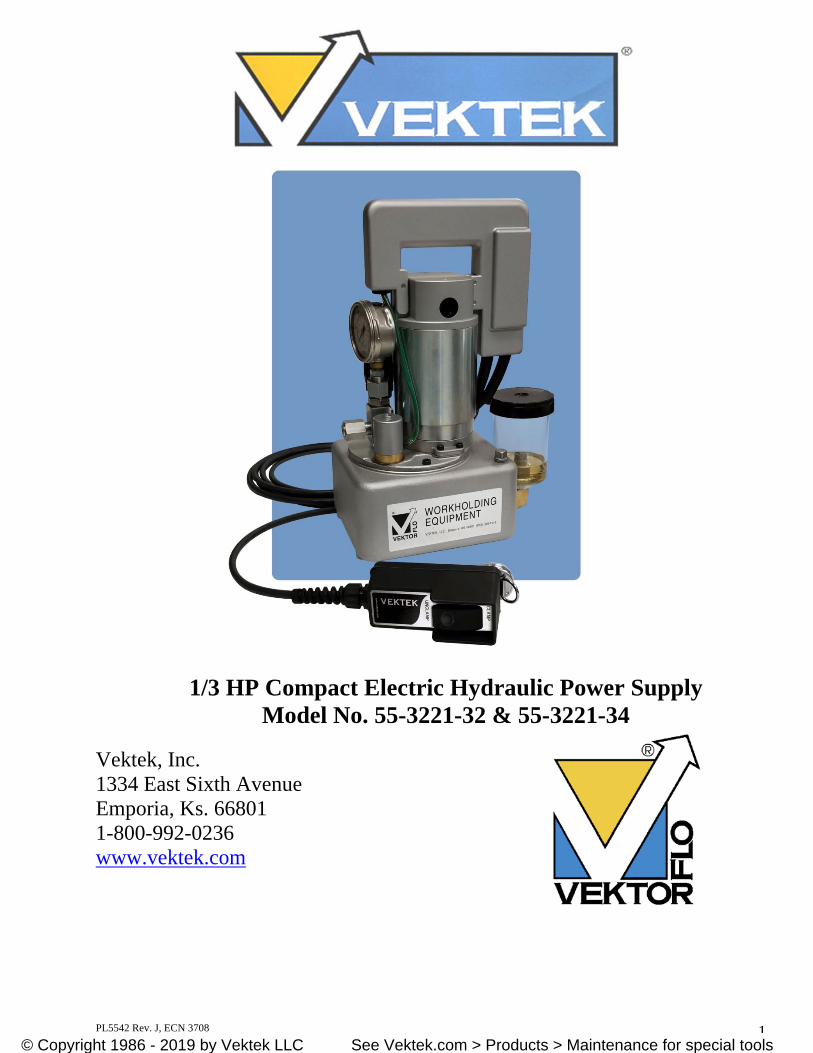
1/3 HP Compact Electric Hydraulic Power Supply Model No. 55-3221-32 & 55-3221-34
Vektek, Inc. 1334 East Sixth Avenue Emporia, Ks. 66801 1-800-992-0236 www.vektek.com
© Copyright 1986 - 2019 by Vektek, Inc. See Vektek.com > Products > Maintenance for special tools© Copyright 1986 - 2019 by Vektek LLC See Vektek.com > Products > Maintenance for special tools
PL5542 Rev. J, ECN 3708 2
VektorFlo is a registered trademark of Vektek, Inc. VEKTEK, INC. RESERVES THE RIGHT TO CHANGE THE SPECIFICATIONS OF THIS POWER SUPPLY UNIT WITHOUT NOTICE, IN AN ONGOING PRODUCT IMPROVEMENT PROCESS. Vektek, Inc. 1334 East Sixth Street Emporia, KS 66801 1-800-992-0236 [email protected] www.vektek.com
Power Supply (SMP-30SK-404) Model No. 55-3221-32
Power Supply Serial No.:_________________________________ In Service Date: ________________________________________ Purchased By: _________________________________________ Purchased For: ________________________________________
© Copyright 1986 - 2019 by Vektek, Inc. See Vektek.com > Products > Maintenance for special tools© Copyright 1986 - 2019 by Vektek LLC See Vektek.com > Products > Maintenance for special tools
PL5542 Rev. J, ECN 3708 3
TABLE OF CONTENTS
Page Preliminary and Safety Information (Section I) 4 Hydraulic Fluid (Section II) 6
A. Hydraulic Fluid MSDS Sheet 7 - 12 Power supply Installation (Section III) 13
A. Specifications B. Set-up
Maintenance (Section IV) 18
A. Intervals B. Wiring Diagram / Schematic C. Parts List
Trouble Shooting (Section V) 24 Warranty and Return Information (Section VI) 26
© Copyright 1986 - 2019 by Vektek, Inc. See Vektek.com > Products > Maintenance for special tools© Copyright 1986 - 2019 by Vektek LLC See Vektek.com > Products > Maintenance for special tools
PL5542 Rev. J, ECN 3708 4
Section I
Preliminary and Safety Information
FAILURE TO HEED THE FOLLOWING INFORMATION WILL VOID WARRANTY
Preliminary Information Most malfunctions in new equipment are the result of improper set-up and operation. Please read and fully understand the entire enclosed information. Remove the power supply from the shipping container. DO NOT remove plugs or valves until unit is ready to be installed to prevent any foreign matter from contaminating the system. Visually inspect all components for shipping damage and correct configuration. Report any damage found to the carrier or factory immediately. Compare motor data plate with power availability. Electrical supply must be of the same rating or equipment damage may occur. This power supply is equipped with an SAE O-ring port for the external hydraulic pressure connection. SAE O-ring fittings seal by compressing a resilient o-ring in a specially designed chamfer in the port. With this type of connection, DO NOT use pipe thread sealing compound, thread sealing tape, or other materials. Such materials may contaminate the hydraulic system and damage the sealing surfaces of the valves. Detection of such materials will void the power supply warranty. This power supply also incorporates a 3/8 NPT fill port that may be used as a return port for double acting systems (additional valving would be required for this implementation). This power supply is equipped with an electric pressure switch that shuts the motor off when it reaches a preset pressure. The motor will automatically restart if the system pressure falls by approximately 10% of pressure setting. The power supply does NOT include a fluid level switch that will shut the motor off if the fluid level is too low. Never run the motor with out sufficient hydraulic oil in the reservoir. When connected to a properly functioning clamping system, hydraulic pressure may bleed down very slowly after the power supply motor stops. Depending upon the size and complexity if the system, the motor should restart only once every two to ten minutes, after the system is fully pressurized.
© Copyright 1986 - 2019 by Vektek, Inc. See Vektek.com > Products > Maintenance for special tools© Copyright 1986 - 2019 by Vektek LLC See Vektek.com > Products > Maintenance for special tools
PL5542 Rev. J, ECN 3708 5
Section I
Preliminary and Safety Information (continued)
Safety
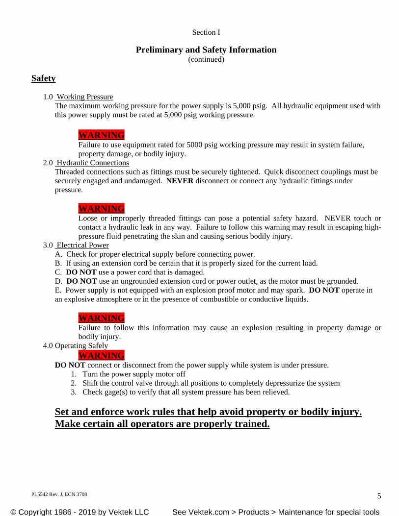
1.0 Working Pressure The maximum working pressure for the power supply is 5,000 psig. All hydraulic equipment used with this power supply must be rated at 5,000 psig working pressure.
WARNING Failure to use equipment rated for 5000 psig working pressure may result in system failure, property damage, or bodily injury.
2.0 Hydraulic Connections Threaded connections such as fittings must be securely tightened. Quick disconnect couplings must be securely engaged and undamaged. NEVER disconnect or connect any hydraulic fittings under pressure.
WARNING Loose or improperly threaded fittings can pose a potential safety hazard. NEVER touch or contact a hydraulic leak in any way. Failure to follow this warning may result in escaping high-pressure fluid penetrating the skin and causing serious bodily injury.
3.0 Electrical Power A. Check for proper electrical supply before connecting power. B. If using an extension cord be certain that it is properly sized for the current load. C. DO NOT use a power cord that is damaged. D. DO NOT use an ungrounded extension cord or power outlet, as the motor must be grounded. E. Power supply is not equipped with an explosion proof motor and may spark. DO NOT operate in an explosive atmosphere or in the presence of combustible or conductive liquids.
WARNING Failure to follow this information may cause an explosion resulting in property damage or bodily injury.
4.0 Operating Safely WARNING
DO NOT connect or disconnect from the power supply while system is under pressure. 1. Turn the power supply motor off 2. Shift the control valve through all positions to completely depressurize the system 3. Check gage(s) to verify that all system pressure has been relieved.
Set and enforce work rules that help avoid property or bodily injury. Make certain all operators are properly trained.
© Copyright 1986 - 2019 by Vektek, Inc. See Vektek.com > Products > Maintenance for special tools© Copyright 1986 - 2019 by Vektek LLC See Vektek.com > Products > Maintenance for special tools
PL5542 Rev. J, ECN 3708 6
Section II
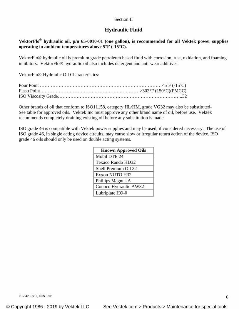
Hydraulic Fluid VektorFlo hydraulic oil, p/n 65-0010-01 (one gallon), is recommended for all Vektek power supplies operating in ambient temperatures above 5°F (-15°C). VektorFlo hydraulic oil is premium grade petroleum based fluid with corrosion, rust, oxidation, and foaming inhibitors. VektorFlo hydraulic oil also includes detergent and anti-wear additives. VektorFlo Hydraulic Oil Characteristics: Pour Point ……………………………………………………………………<5ºF (-15ºC) Flash Point…………………………………………….…………>302°F (150°C)(PMCC) ISO Viscosity Grade……………………………………………………………………..32 Other brands of oil that conform to ISO11158, category HL/HM, grade VG32 may also be substituted- See table for approved oils. Vektek Inc must approve any other brand name of oil, before use. Vektek recommends completely draining existing oil before any substitution is made. ISO grade 46 is compatible with Vektek power supplies and may be used, if considered necessary. The use of ISO grade 46, in single acting device circuits, may cause slow or irregular return action of the device. ISO grade 46 oils should only be used on double acting systems.
Known Approved Oils Mobil DTE 24 Texaco Rando HD32 Shell Premium Oil 32 Exxon NUTO H32 Phillips Magnus A Conoco Hydraulic AW32 Lubriplate HO-0
© Copyright 1986 - 2019 by Vektek, Inc. See Vektek.com > Products > Maintenance for special tools© Copyright 1986 - 2019 by Vektek LLC See Vektek.com > Products > Maintenance for special tools
PL5542 Rev. J, ECN 3708 7
Section II Vektek Hydraulic Fluid ENGINEERING NOTICE P/N 65-0010-01 EN-6500_EN Revision H
Hydraulic Fluid (continued)
Safety Data Sheet According to OSHA HCS 2012 (29 CFR 1910.1200)
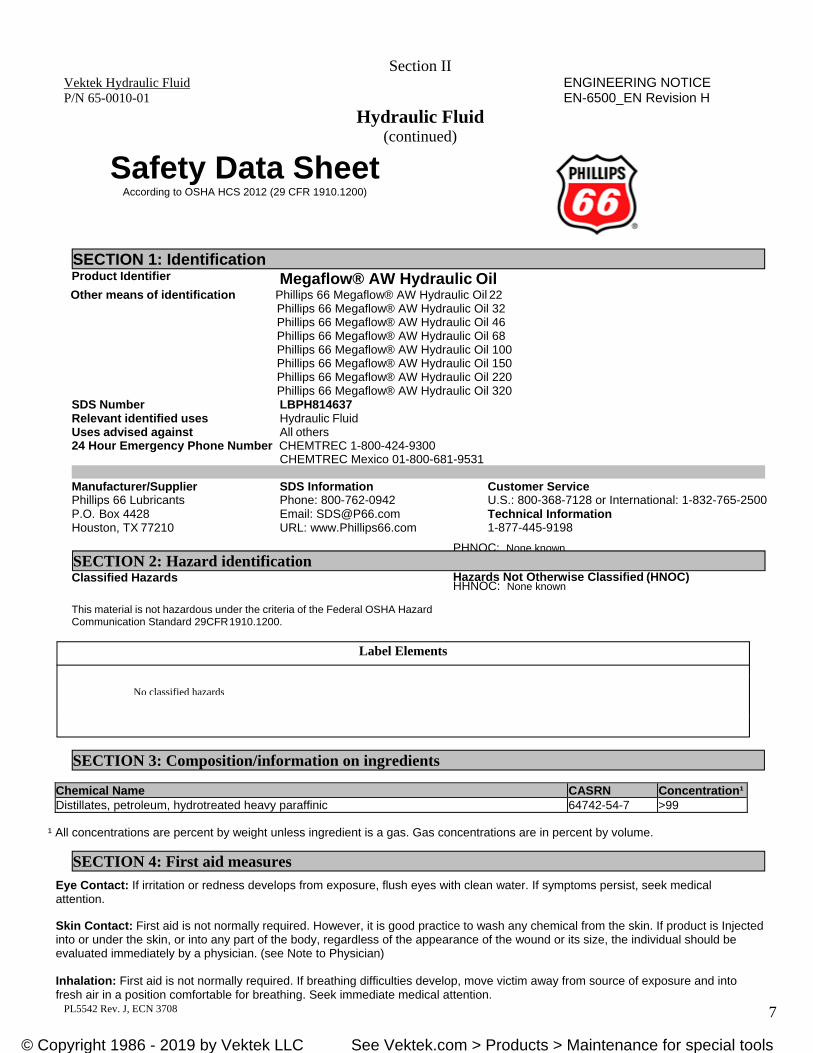
SECTION 1: Identification Product Identifier Megaflow® AW Hydraulic Oil
Other means of identification Phillips 66 Megaflow® AW Hydraulic Oil 22 Phillips 66 Megaflow® AW Hydraulic Oil 32 Phillips 66 Megaflow® AW Hydraulic Oil 46 Phillips 66 Megaflow® AW Hydraulic Oil 68 Phillips 66 Megaflow® AW Hydraulic Oil 100 Phillips 66 Megaflow® AW Hydraulic Oil 150 Phillips 66 Megaflow® AW Hydraulic Oil 220 Phillips 66 Megaflow® AW Hydraulic Oil 320
SDS Number LBPH814637 Relevant identified uses Hydraulic Fluid Uses advised against All others 24 Hour Emergency Phone Number CHEMTREC 1-800-424-9300
CHEMTREC Mexico 01-800-681-9531
Manufacturer/Supplier Phillips 66 Lubricants P.O. Box 4428 Houston, TX 77210
SDS Information Phone: 800-762-0942 Email: [email protected] URL: www.Phillips66.com
Customer Service U.S.: 800-368-7128 or International: 1-832-765-2500 Technical Information 1-877-445-9198
Classified Hazards Hazards Not Otherwise Classified (HNOC)
This material is not hazardous under the criteria of the Federal OSHA Hazard Communication Standard 29CFR 1910.1200.
PHNOC: None known
HHNOC: None known
Chemical Name CASRN Concentration¹Distillates, petroleum, hydrotreated heavy paraffinic 64742-54-7 >99
¹ All concentrations are percent by weight unless ingredient is a gas. Gas concentrations are in percent by volume.
Eye Contact: If irritation or redness develops from exposure, flush eyes with clean water. If symptoms persist, seek medical attention.
Skin Contact: First aid is not normally required. However, it is good practice to wash any chemical from the skin. If product is Injected into or under the skin, or into any part of the body, regardless of the appearance of the wound or its size, the individual should be evaluated immediately by a physician. (see Note to Physician) Inhalation: First aid is not normally required. If breathing difficulties develop, move victim away from source of exposure and into fresh air in a position comfortable for breathing. Seek immediate medical attention.
SECTION 2: Hazard identification
Label Elements
No classified hazards
SECTION 3: Composition/information on ingredients
SECTION 4: First aid measures
© Copyright 1986 - 2019 by Vektek, Inc. See Vektek.com > Products > Maintenance for special tools© Copyright 1986 - 2019 by Vektek LLC See Vektek.com > Products > Maintenance for special tools
PL5542 Rev. J, ECN 3708 8
Ingestion: First aid is not normally required; however, if swallowed and symptoms develop, seek medical attention.
Most important symptoms and effects, both acute and delayed: Inhalation of oil mists or vapors generated at elevated temperatures may cause respiratory irritation. Accidental ingestion can result in minor irritation of the digestive tract, nausea and diarrhea.
Notes to Physician: Acute aspirations of large amounts of oil-laden material may produce a serious aspiration pneumonia. Patients who aspirate these oils should be followed for the development of long-term sequelae. Inhalation exposure to oil mists below current workplace exposure limits is unlikely to cause pulmonary abnormalities. When using high-pressure equipment, injection of product under the skin can occur. In this case, the casualty should be sent immediately to the hospital. Do not wait for symptoms to develop. High-pressure hydrocarbon injection injuries may produce substantial necrosis of underlying tissue despite an innocuous appearing external wound. These injuries often require extensive emergency surgical debridement and all injuries should be evaluated by a specialist in order to assess the extent of injury. Early surgical treatment within the first few hours may significantly reduce the ultimate extent of injury.
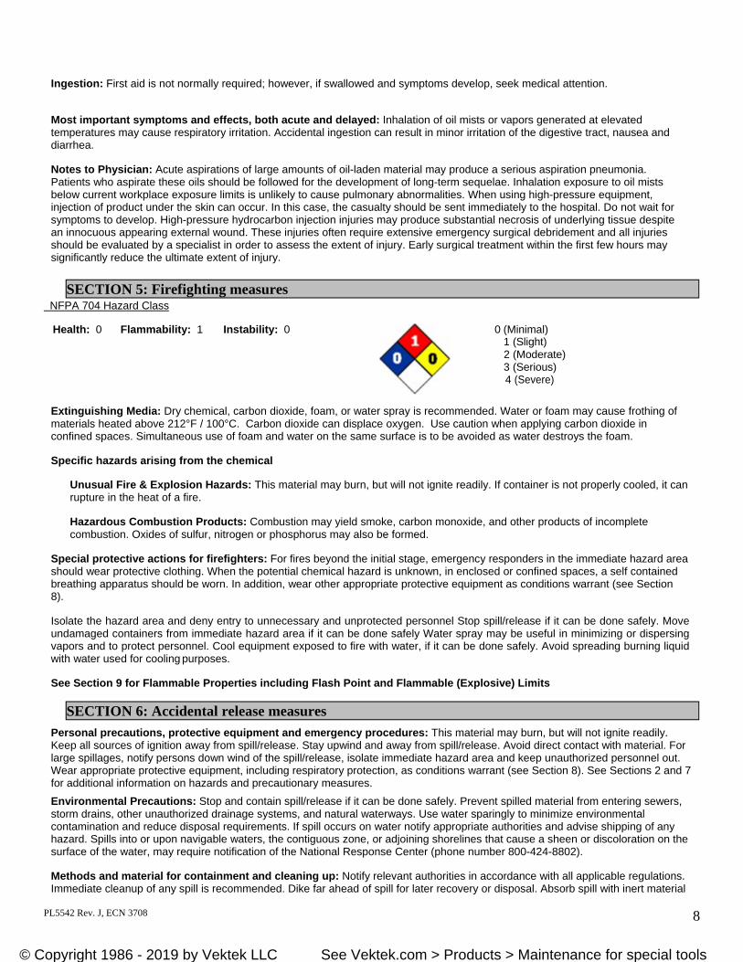
NFPA 704 Hazard Class
Health: 0 Flammability: 1 Instability: 0 0 (Minimal) 1 (Slight) 2 (Moderate) 3 (Serious) 4 (Severe)
Extinguishing Media: Dry chemical, carbon dioxide, foam, or water spray is recommended. Water or foam may cause frothing of materials heated above 212°F / 100°C. Carbon dioxide can displace oxygen. Use caution when applying carbon dioxide in confined spaces. Simultaneous use of foam and water on the same surface is to be avoided as water destroys the foam.
Specific hazards arising from the chemical
Unusual Fire & Explosion Hazards: This material may burn, but will not ignite readily. If container is not properly cooled, it can rupture in the heat of a fire.
Hazardous Combustion Products: Combustion may yield smoke, carbon monoxide, and other products of incomplete combustion. Oxides of sulfur, nitrogen or phosphorus may also be formed.
Special protective actions for firefighters: For fires beyond the initial stage, emergency responders in the immediate hazard area should wear protective clothing. When the potential chemical hazard is unknown, in enclosed or confined spaces, a self contained breathing apparatus should be worn. In addition, wear other appropriate protective equipment as conditions warrant (see Section 8).
Isolate the hazard area and deny entry to unnecessary and unprotected personnel Stop spill/release if it can be done safely. Move undamaged containers from immediate hazard area if it can be done safely Water spray may be useful in minimizing or dispersing vapors and to protect personnel. Cool equipment exposed to fire with water, if it can be done safely. Avoid spreading burning liquid with water used for cooling purposes.
See Section 9 for Flammable Properties including Flash Point and Flammable (Explosive) Limits
Personal precautions, protective equipment and emergency procedures: This material may burn, but will not ignite readily. Keep all sources of ignition away from spill/release. Stay upwind and away from spill/release. Avoid direct contact with material. For large spillages, notify persons down wind of the spill/release, isolate immediate hazard area and keep unauthorized personnel out. Wear appropriate protective equipment, including respiratory protection, as conditions warrant (see Section 8). See Sections 2 and 7 for additional information on hazards and precautionary measures.
Environmental Precautions: Stop and contain spill/release if it can be done safely. Prevent spilled material from entering sewers, storm drains, other unauthorized drainage systems, and natural waterways. Use water sparingly to minimize environmental contamination and reduce disposal requirements. If spill occurs on water notify appropriate authorities and advise shipping of any hazard. Spills into or upon navigable waters, the contiguous zone, or adjoining shorelines that cause a sheen or discoloration on the surface of the water, may require notification of the National Response Center (phone number 800-424-8802).
Methods and material for containment and cleaning up: Notify relevant authorities in accordance with all applicable regulations. Immediate cleanup of any spill is recommended. Dike far ahead of spill for later recovery or disposal. Absorb spill with inert material
SECTION 5: Firefighting measures
SECTION 6: Accidental release measures
© Copyright 1986 - 2019 by Vektek, Inc. See Vektek.com > Products > Maintenance for special tools© Copyright 1986 - 2019 by Vektek LLC See Vektek.com > Products > Maintenance for special tools
PL5542 Rev. J, ECN 3708 9
such as sand or vermiculite, and place in suitable container for disposal. If spilled on water remove with appropriate methods (e.g. skimming, booms or absorbents). In case of soil contamination, remove contaminated soil for remediation or disposal, in accordance with local regulations.
Recommended measures are based on the most likely spillage scenarios for this material; however local conditions and regulations may influence or limit the choice of appropriate actions to be taken. See Section 13 for information on appropriate disposal.
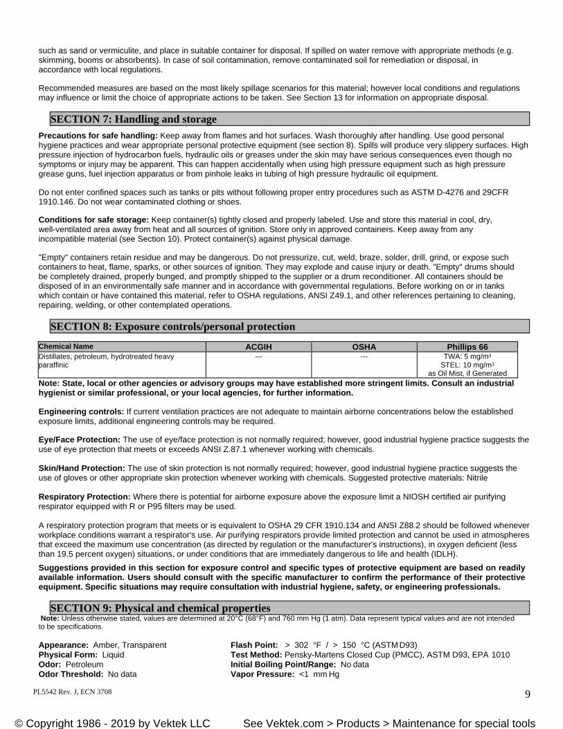
Precautions for safe handling: Keep away from flames and hot surfaces. Wash thoroughly after handling. Use good personal hygiene practices and wear appropriate personal protective equipment (see section 8). Spills will produce very slippery surfaces. High pressure injection of hydrocarbon fuels, hydraulic oils or greases under the skin may have serious consequences even though no symptoms or injury may be apparent. This can happen accidentally when using high pressure equipment such as high pressure grease guns, fuel injection apparatus or from pinhole leaks in tubing of high pressure hydraulic oil equipment.
Do not enter confined spaces such as tanks or pits without following proper entry procedures such as ASTM D-4276 and 29CFR 1910.146. Do not wear contaminated clothing or shoes.
Conditions for safe storage: Keep container(s) tightly closed and properly labeled. Use and store this material in cool, dry, well-ventilated area away from heat and all sources of ignition. Store only in approved containers. Keep away from any incompatible material (see Section 10). Protect container(s) against physical damage.
"Empty" containers retain residue and may be dangerous. Do not pressurize, cut, weld, braze, solder, drill, grind, or expose such containers to heat, flame, sparks, or other sources of ignition. They may explode and cause injury or death. "Empty" drums should be completely drained, properly bunged, and promptly shipped to the supplier or a drum reconditioner. All containers should be disposed of in an environmentally safe manner and in accordance with governmental regulations. Before working on or in tanks which contain or have contained this material, refer to OSHA regulations, ANSI Z49.1, and other references pertaining to cleaning, repairing, welding, or other contemplated operations.
Chemical Name ACGIH OSHA Phillips 66Distillates, petroleum, hydrotreated heavy paraffinic
--- --- TWA: 5 mg/m3
STEL: 10 mg/m3
as Oil Mist, if Generated Note: State, local or other agencies or advisory groups may have established more stringent limits. Consult an industrial hygienist or similar professional, or your local agencies, for further information.
Engineering controls: If current ventilation practices are not adequate to maintain airborne concentrations below the established exposure limits, additional engineering controls may be required.
Eye/Face Protection: The use of eye/face protection is not normally required; however, good industrial hygiene practice suggests the use of eye protection that meets or exceeds ANSI Z.87.1 whenever working with chemicals.
Skin/Hand Protection: The use of skin protection is not normally required; however, good industrial hygiene practice suggests the use of gloves or other appropriate skin protection whenever working with chemicals. Suggested protective materials: Nitrile
Respiratory Protection: Where there is potential for airborne exposure above the exposure limit a NIOSH certified air purifying respirator equipped with R or P95 filters may be used.
A respiratory protection program that meets or is equivalent to OSHA 29 CFR 1910.134 and ANSI Z88.2 should be followed whenever workplace conditions warrant a respirator's use. Air purifying respirators provide limited protection and cannot be used in atmospheres that exceed the maximum use concentration (as directed by regulation or the manufacturer's instructions), in oxygen deficient (less than 19.5 percent oxygen) situations, or under conditions that are immediately dangerous to life and health (IDLH).
Suggestions provided in this section for exposure control and specific types of protective equipment are based on readily available information. Users should consult with the specific manufacturer to confirm the performance of their protective equipment. Specific situations may require consultation with industrial hygiene, safety, or engineering professionals.
Note: Unless otherwise stated, values are determined at 20°C (68°F) and 760 mm Hg (1 atm). Data represent typical values and are not intended to be specifications.
Appearance: Amber, Transparent Flash Point: > 302 °F / > 150 °C (ASTM D93) Physical Form: Liquid Test Method: Pensky-Martens Closed Cup (PMCC), ASTM D93, EPA 1010 Odor: Petroleum Initial Boiling Point/Range: No data Odor Threshold: No data Vapor Pressure: <1 mm Hg
SECTION 7: Handling and storage
SECTION 8: Exposure controls/personal protection
SECTION 9: Physical and chemical properties
© Copyright 1986 - 2019 by Vektek, Inc. See Vektek.com > Products > Maintenance for special tools© Copyright 1986 - 2019 by Vektek LLC See Vektek.com > Products > Maintenance for special tools
PL5542 Rev. J, ECN 3708 10
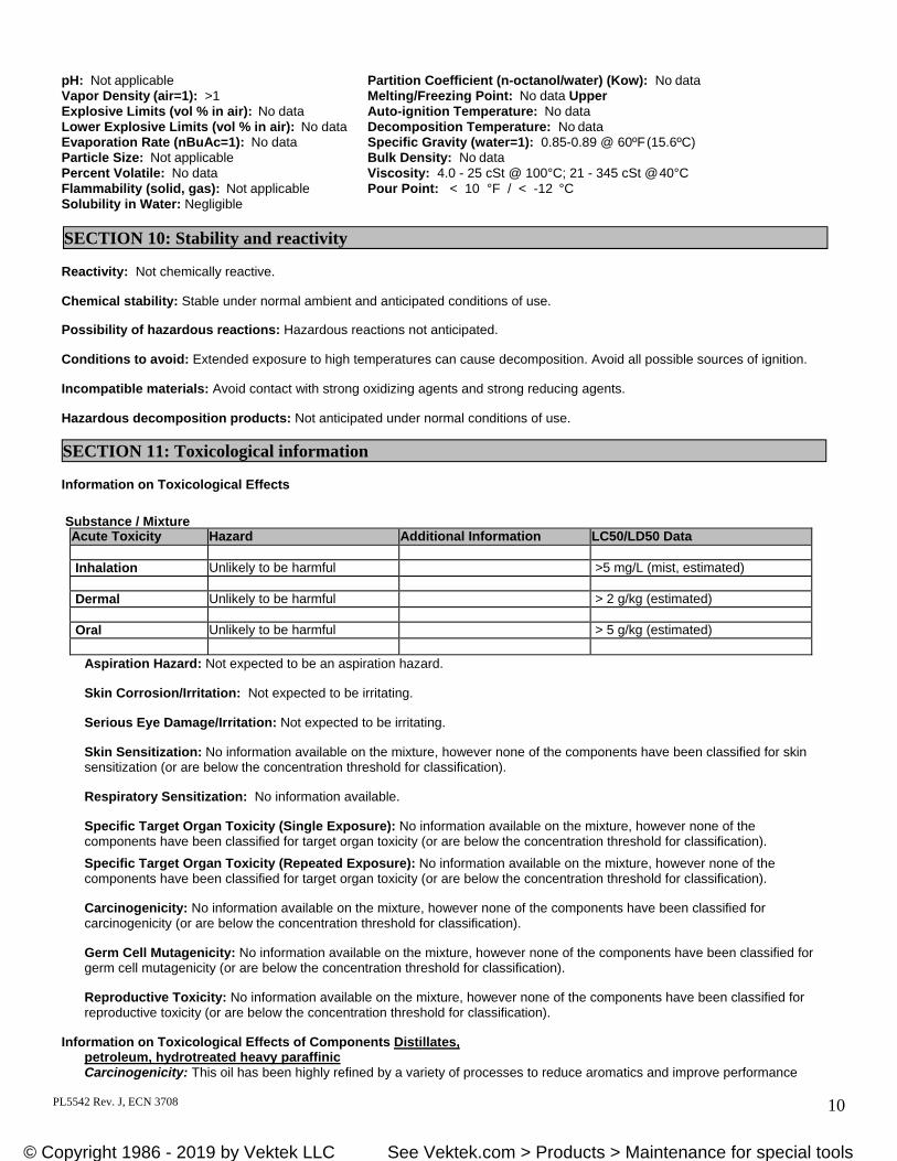
pH: Not applicable Partition Coefficient (n-octanol/water) (Kow): No data Vapor Density (air=1): >1 Melting/Freezing Point: No data Upper Explosive Limits (vol % in air): No data Auto-ignition Temperature: No data Lower Explosive Limits (vol % in air): No data Decomposition Temperature: No data Evaporation Rate (nBuAc=1): No data Specific Gravity (water=1): 0.85-0.89 @ 60ºF (15.6ºC) Particle Size: Not applicable Bulk Density: No data Percent Volatile: No data Viscosity: 4.0 - 25 cSt @ 100°C; 21 - 345 cSt @ 40°C Flammability (solid, gas): Not applicable Pour Point: < 10 °F / < -12 °C Solubility in Water: Negligible
Reactivity: Not chemically reactive.
Chemical stability: Stable under normal ambient and anticipated conditions of use.
Possibility of hazardous reactions: Hazardous reactions not anticipated.
Conditions to avoid: Extended exposure to high temperatures can cause decomposition. Avoid all possible sources of ignition.
Incompatible materials: Avoid contact with strong oxidizing agents and strong reducing agents.
Hazardous decomposition products: Not anticipated under normal conditions of use.
Information on Toxicological Effects
Substance / Mixture
Aspiration Hazard: Not expected to be an aspiration hazard.
Skin Corrosion/Irritation: Not expected to be irritating.
Serious Eye Damage/Irritation: Not expected to be irritating.
Skin Sensitization: No information available on the mixture, however none of the components have been classified for skin sensitization (or are below the concentration threshold for classification).
Respiratory Sensitization: No information available.
Specific Target Organ Toxicity (Single Exposure): No information available on the mixture, however none of the components have been classified for target organ toxicity (or are below the concentration threshold for classification).
Specific Target Organ Toxicity (Repeated Exposure): No information available on the mixture, however none of the components have been classified for target organ toxicity (or are below the concentration threshold for classification).
Carcinogenicity: No information available on the mixture, however none of the components have been classified for carcinogenicity (or are below the concentration threshold for classification).
Germ Cell Mutagenicity: No information available on the mixture, however none of the components have been classified for germ cell mutagenicity (or are below the concentration threshold for classification).
Reproductive Toxicity: No information available on the mixture, however none of the components have been classified for reproductive toxicity (or are below the concentration threshold for classification).
Information on Toxicological Effects of Components Distillates,
petroleum, hydrotreated heavy paraffinic Carcinogenicity: This oil has been highly refined by a variety of processes to reduce aromatics and improve performance
SECTION 10: Stability and reactivity
SECTION 11: Toxicological information
Acute Toxicity Hazard Additional Information LC50/LD50 Data
Inhalation Unlikely to be harmful >5 mg/L (mist, estimated)
Dermal Unlikely to be harmful > 2 g/kg (estimated)
Oral Unlikely to be harmful > 5 g/kg (estimated)
© Copyright 1986 - 2019 by Vektek, Inc. See Vektek.com > Products > Maintenance for special tools© Copyright 1986 - 2019 by Vektek LLC See Vektek.com > Products > Maintenance for special tools
PL5542 Rev. J, ECN 3708 11
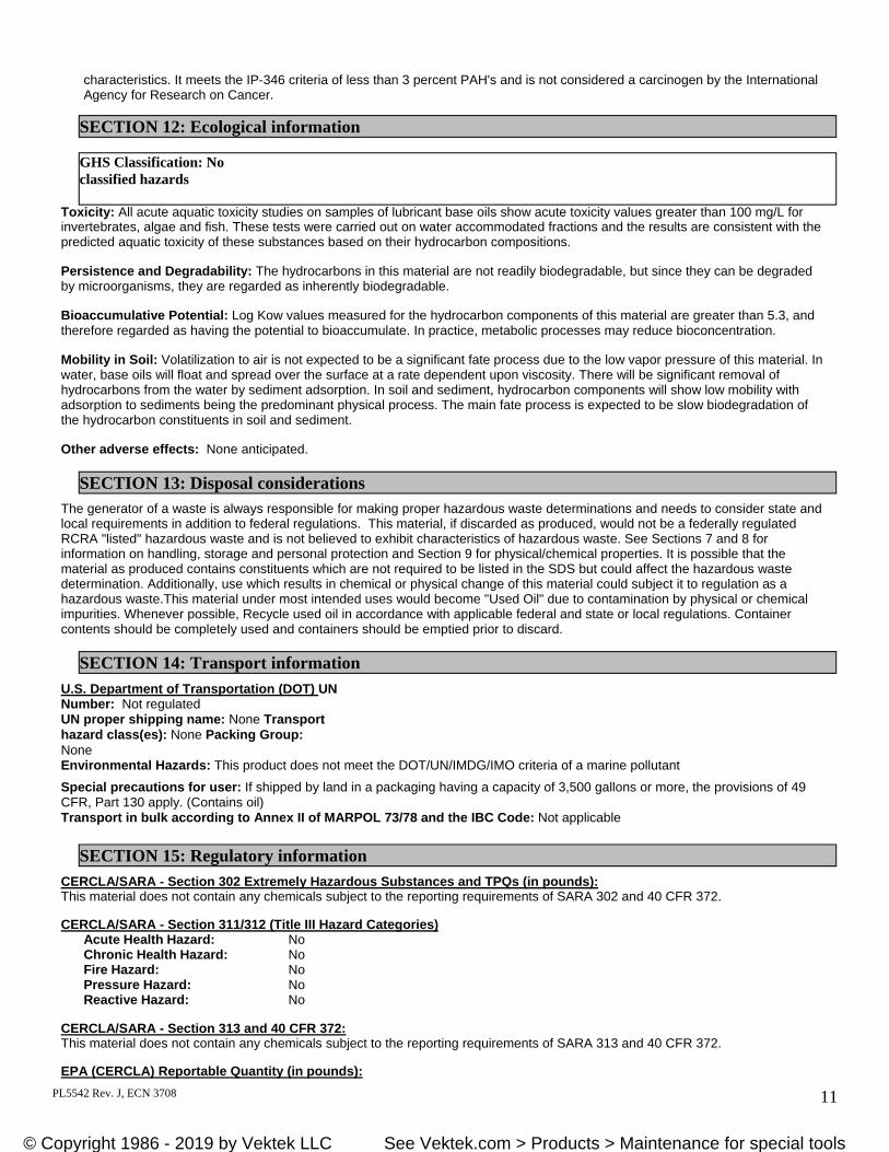
characteristics. It meets the IP-346 criteria of less than 3 percent PAH's and is not considered a carcinogen by the International Agency for Research on Cancer.
Toxicity: All acute aquatic toxicity studies on samples of lubricant base oils show acute toxicity values greater than 100 mg/L for invertebrates, algae and fish. These tests were carried out on water accommodated fractions and the results are consistent with the predicted aquatic toxicity of these substances based on their hydrocarbon compositions.
Persistence and Degradability: The hydrocarbons in this material are not readily biodegradable, but since they can be degraded by microorganisms, they are regarded as inherently biodegradable.
Bioaccumulative Potential: Log Kow values measured for the hydrocarbon components of this material are greater than 5.3, and therefore regarded as having the potential to bioaccumulate. In practice, metabolic processes may reduce bioconcentration.
Mobility in Soil: Volatilization to air is not expected to be a significant fate process due to the low vapor pressure of this material. In water, base oils will float and spread over the surface at a rate dependent upon viscosity. There will be significant removal of hydrocarbons from the water by sediment adsorption. In soil and sediment, hydrocarbon components will show low mobility with adsorption to sediments being the predominant physical process. The main fate process is expected to be slow biodegradation of the hydrocarbon constituents in soil and sediment.
Other adverse effects: None anticipated.
The generator of a waste is always responsible for making proper hazardous waste determinations and needs to consider state and local requirements in addition to federal regulations. This material, if discarded as produced, would not be a federally regulated RCRA "listed" hazardous waste and is not believed to exhibit characteristics of hazardous waste. See Sections 7 and 8 for information on handling, storage and personal protection and Section 9 for physical/chemical properties. It is possible that the material as produced contains constituents which are not required to be listed in the SDS but could affect the hazardous waste determination. Additionally, use which results in chemical or physical change of this material could subject it to regulation as a hazardous waste.This material under most intended uses would become "Used Oil" due to contamination by physical or chemical impurities. Whenever possible, Recycle used oil in accordance with applicable federal and state or local regulations. Container contents should be completely used and containers should be emptied prior to discard.
U.S. Department of Transportation (DOT) UN Number: Not regulated UN proper shipping name: None Transport hazard class(es): None Packing Group: None Environmental Hazards: This product does not meet the DOT/UN/IMDG/IMO criteria of a marine pollutant
Special precautions for user: If shipped by land in a packaging having a capacity of 3,500 gallons or more, the provisions of 49 CFR, Part 130 apply. (Contains oil) Transport in bulk according to Annex II of MARPOL 73/78 and the IBC Code: Not applicable
CERCLA/SARA - Section 302 Extremely Hazardous Substances and TPQs (in pounds): This material does not contain any chemicals subject to the reporting requirements of SARA 302 and 40 CFR 372.
CERCLA/SARA - Section 311/312 (Title III Hazard Categories) Acute Health Hazard: No Chronic Health Hazard: No Fire Hazard: No Pressure Hazard: No Reactive Hazard: No
CERCLA/SARA - Section 313 and 40 CFR 372: This material does not contain any chemicals subject to the reporting requirements of SARA 313 and 40 CFR 372.
EPA (CERCLA) Reportable Quantity (in pounds):
SECTION 12: Ecological information
GHS Classification: No classified hazards
SECTION 13: Disposal considerations
SECTION 14: Transport information
SECTION 15: Regulatory information
© Copyright 1986 - 2019 by Vektek, Inc. See Vektek.com > Products > Maintenance for special tools© Copyright 1986 - 2019 by Vektek LLC See Vektek.com > Products > Maintenance for special tools
PL5542 Rev. J, ECN 3708 12
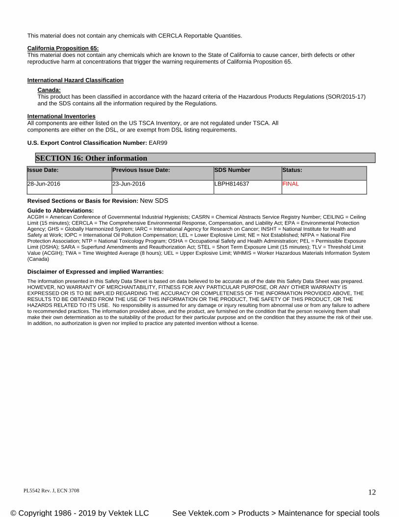
This material does not contain any chemicals with CERCLA Reportable Quantities.
California Proposition 65: This material does not contain any chemicals which are known to the State of California to cause cancer, birth defects or other reproductive harm at concentrations that trigger the warning requirements of California Proposition 65.
International Hazard Classification
Canada: This product has been classified in accordance with the hazard criteria of the Hazardous Products Regulations (SOR/2015-17) and the SDS contains all the information required by the Regulations.
International Inventories All components are either listed on the US TSCA Inventory, or are not regulated under TSCA. All components are either on the DSL, or are exempt from DSL listing requirements.
U.S. Export Control Classification Number: EAR99
Issue Date: Previous Issue Date: SDS Number Status:
28-Jun-2016 23-Jun-2016 LBPH814637 FINAL
Revised Sections or Basis for Revision: New SDS Guide to Abbreviations: ACGIH = American Conference of Governmental Industrial Hygienists; CASRN = Chemical Abstracts Service Registry Number; CEILING = Ceiling Limit (15 minutes); CERCLA = The Comprehensive Environmental Response, Compensation, and Liability Act; EPA = Environmental Protection Agency; GHS = Globally Harmonized System; IARC = International Agency for Research on Cancer; INSHT = National Institute for Health and Safety at Work; IOPC = International Oil Pollution Compensation; LEL = Lower Explosive Limit; NE = Not Established; NFPA = National Fire Protection Association; NTP = National Toxicology Program; OSHA = Occupational Safety and Health Administration; PEL = Permissible Exposure Limit (OSHA); SARA = Superfund Amendments and Reauthorization Act; STEL = Short Term Exposure Limit (15 minutes); TLV = Threshold Limit Value (ACGIH); TWA = Time Weighted Average (8 hours); UEL = Upper Explosive Limit; WHMIS = Worker Hazardous Materials Information System (Canada)
Disclaimer of Expressed and implied Warranties:
The information presented in this Safety Data Sheet is based on data believed to be accurate as of the date this Safety Data Sheet was prepared. HOWEVER, NO WARRANTY OF MERCHANTABILITY, FITNESS FOR ANY PARTICULAR PURPOSE, OR ANY OTHER WARRANTY IS EXPRESSED OR IS TO BE IMPLIED REGARDING THE ACCURACY OR COMPLETENESS OF THE INFORMATION PROVIDED ABOVE, THE RESULTS TO BE OBTAINED FROM THE USE OF THIS INFORMATION OR THE PRODUCT, THE SAFETY OF THIS PRODUCT, OR THE HAZARDS RELATED TO ITS USE. No responsibility is assumed for any damage or injury resulting from abnormal use or from any failure to adhere to recommended practices. The information provided above, and the product, are furnished on the condition that the person receiving them shall make their own determination as to the suitability of the product for their particular purpose and on the condition that they assume the risk of their use. In addition, no authorization is given nor implied to practice any patented invention without a license.
SECTION 16: Other information
© Copyright 1986 - 2019 by Vektek, Inc. See Vektek.com > Products > Maintenance for special tools© Copyright 1986 - 2019 by Vektek LLC See Vektek.com > Products > Maintenance for special tools
PL5542 Rev. J, ECN 3708 13
Section III
Power Supply Installation
Specifications This unit is an automatic pressure holding power supply with valving and control switches included in the assembly. As shipped, it is ready to use upon connection to an appropriate power supply and hydraulic circuit. When actuated, the pump will automatically build and hold pressure to a preset level and restart if a pressure drop occurs. The adjustable pressure switch provides for hydraulic pressure at the output port, from approximately 725 psi to 5000 psi. This pump is designed for intermittent duty and the motor should not be allowed to run for more than two minutes (continuously) at pressure. Pump Output: Maximum Operating Pressure ...........................................................5,000 psi (35 MPa) Low pressure output ..........................................................................215 psi (1.5 MPa) Low pressure / high flow volume ......................................................120 in³/min (2 L/m) High pressure / low flow volume .......................................................12 in³/min (.2 L/m) Motor: Watts ..................................................................................................250 Full load Amps ...................................................................................7.2 Voltage ...............................................................................................115 VAC ± 5% Phase ..................................................................................................1 Ph, 50/60 Hz Insulation............................................................................................Class E Pressure Switch: Pressure adjustment range..................................................................725 – 5000 psi (5-35 MPa) Reset differential ................................................................................360 – 650 psi (2.5 – 4.5 MPa) Electrical ............................................................................................250 V – 3 Amperes Hydraulic Oil: Grade: .................................................................................................ISO VG32 Optimum oil temperature ...................................................................40 – 140° F (5 – 60° C) Reservoir Capacity: Nominal: ............................................................................................122 in³ (2.0 L) Usable: ...............................................................................................108 in³ (1.8 L) Weight (approx. with oil): ...............................................................32 lb (14.5 kg) Power supply Ambient Operating Temp. ......................................32-104°F (0-40°C) The motor is equipped with a three pronged grounding plug to fit a three prong grounded receptacle. Do not modify the plug or use a two-pronged adapter. If an extension cord is used, it must also have a three pronged plug and be of the wire gauge listed in the following table.
Cord Length Wire Gauge
Up to 50 Feet 16-3 AWG
Over 50 Feet 14-3 AWG
© Copyright 1986 - 2019 by Vektek, Inc. See Vektek.com > Products > Maintenance for special tools© Copyright 1986 - 2019 by Vektek LLC See Vektek.com > Products > Maintenance for special tools
PL5542 Rev. J, ECN 3708 14
Section III
Power Supply Installation (continued)
Set-up BEFORE turning the power supply on, check the oil level in the reservoir with the reservoir air vent (dip-
stick). Add oil, Vektek p/n 65-0010-01, as necessary. Verify that all desired gage, valve, hose, and quick coupler connections are rated for a 5000 psi working
pressure, are properly tightened. The power supply is equipped with an SAE 6 O-ring port (I.A.W. SAE J1926) located on the front surface
of the manifold block. Use ONLY SAE O-ring style fittings to connect to this port. The 3/8 NPT fill port may be used as a return port for double acting systems (additional valving would be required for this implementation).
During the initial set-up of any new system, it recommended that the pressure switch be set to the minimum pressure required to operate the system components. Cycling the system at low pressure should reveal most oversights in the installation such as stroke, interference, loose fitting connections, and clamp positioning.
CAUTION
When starting any power supply, care should be taken to avoid sudden or undesired device movement. Always make sure that control valves are set to the desired position.
In a very few cases, you may be required to close the air vent, start the motor and lay the power supply on its side. This will help to prime the pump. Set the power supply upright and reopen the air vent when the device begins to advance.
Pressure Switch Adjustment The power supply must be connected to a device(s), rated at 5,000 psig, which requires fluid volume in
order to set the pressure switch.
To set the pressure, rotate the adjuster sleeve on the pressure switch to increase or decrease the system pressure. The numbers on the switch are indicators only, and are marked in Megapascals (MPa). 1 MPa is approximately 145 psi. Final pressure readings should be made with the PSI gauge mounted on the pump.
NOTICE The pressure switch supplied with the power supply is for the control of the motor only. It is not intended to
interface with machine controllers or to be used for process control. If a pressure switch is required for process control, a separate switch should be installed down stream of the control valve.
Actual system pressure may exceed the pressure switch setting due to inertia, which causes the pump motor to spin for several rotations after being electrically disconnected. The pressure setting may have to be adjusted to compensate for the small over pressure condition. This condition will be more noticeable in small volume circuits. If the pressure is difficult to control, a small accumulator (Vektek Cat. No. 10-1014-01) may be added to the circuit.
© Copyright 1986 - 2019 by Vektek, Inc. See Vektek.com > Products > Maintenance for special tools© Copyright 1986 - 2019 by Vektek LLC See Vektek.com > Products > Maintenance for special tools
PL5542 Rev. J, ECN 3708 15
Section III
Power Supply Installation (continued)
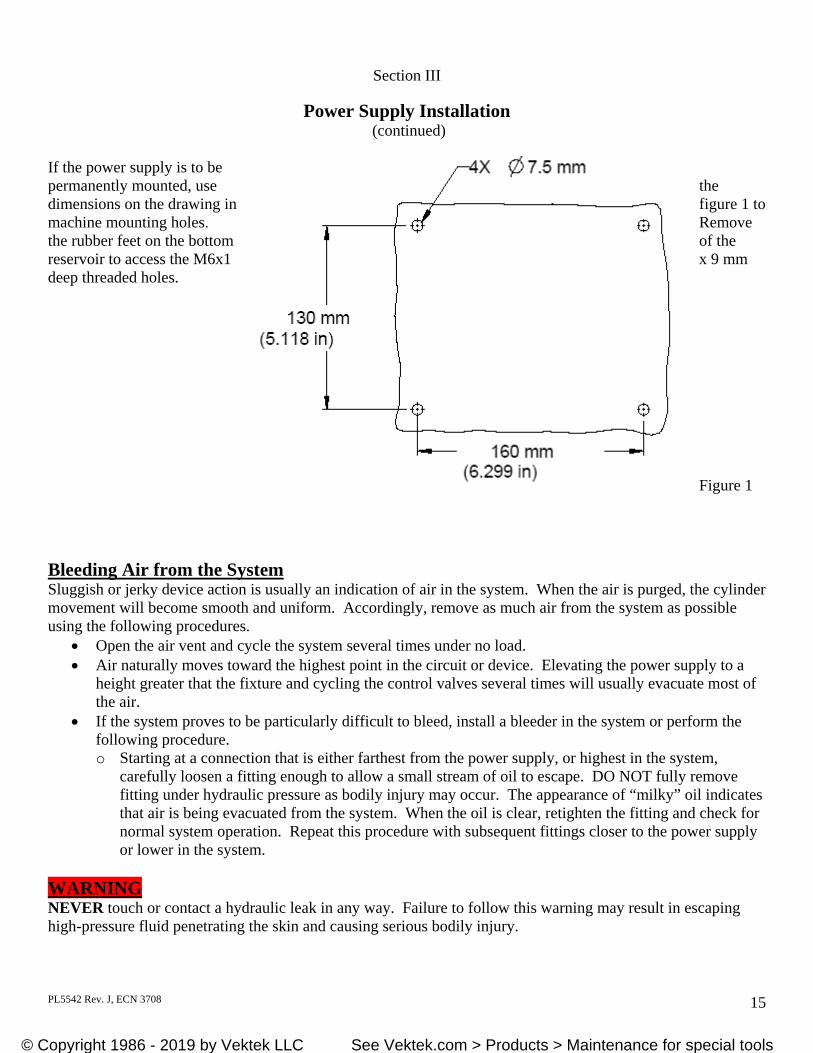
If the power supply is to be permanently mounted, use the dimensions on the drawing in figure 1 to machine mounting holes. Remove the rubber feet on the bottom of the reservoir to access the M6x1 x 9 mm deep threaded holes. Figure 1 Bleeding Air from the System Sluggish or jerky device action is usually an indication of air in the system. When the air is purged, the cylinder movement will become smooth and uniform. Accordingly, remove as much air from the system as possible using the following procedures.
Open the air vent and cycle the system several times under no load. Air naturally moves toward the highest point in the circuit or device. Elevating the power supply to a
height greater that the fixture and cycling the control valves several times will usually evacuate most of the air.
If the system proves to be particularly difficult to bleed, install a bleeder in the system or perform the following procedure. o Starting at a connection that is either farthest from the power supply, or highest in the system,
carefully loosen a fitting enough to allow a small stream of oil to escape. DO NOT fully remove fitting under hydraulic pressure as bodily injury may occur. The appearance of “milky” oil indicates that air is being evacuated from the system. When the oil is clear, retighten the fitting and check for normal system operation. Repeat this procedure with subsequent fittings closer to the power supply or lower in the system.
WARNING NEVER touch or contact a hydraulic leak in any way. Failure to follow this warning may result in escaping high-pressure fluid penetrating the skin and causing serious bodily injury.
© Copyright 1986 - 2019 by Vektek, Inc. See Vektek.com > Products > Maintenance for special tools© Copyright 1986 - 2019 by Vektek LLC See Vektek.com > Products > Maintenance for special tools
PL5542 Rev. J, ECN 3708 16
Section III
Power Supply Installation (continued)
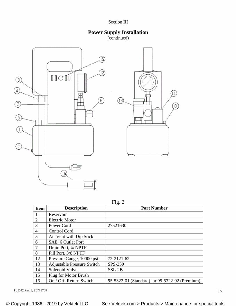
Operation (refer to Figure 2) Connect the clamping circuit to the SAE 6 pressure port (6) Adjust the pressure switch to the lowest setting (13) Set the control toggle switch to the OFF position (16) Open the air vent counterclockwise, one to two turns (5) Connect the power supply to an appropriate electrical supply (3) The power supply is now ready for test operation.
o Toggle the switch (16) to the ON position to start the pump and allow the system to pressurize. The motor will stop when the system pressure reaches the level set by the pressure switch. If a pressure loss of 500 PSI (approx.) or more occurs while the switch is in the ON position, the motor will start and return the pressure back to the preset pressure. A pressure lower than the switch setting may be obtained at any time during the advancing stroke by moving the switch to the OFF position. Do not leave the toggle switch in the OFF position. The Off position will not allow the power supply to automatically start if a pressure loss occurs.
o Verify system pressure with the gauge (12). Rotating the pressure switch sleeve to a higher number will result in the motor starting up and building pressure to the adjusted pressure. Actual system pressure may exceed the pressure switch setting due to inertia which causes the pump motor to spin after being electrically disconnected. On small volume circuits, the pressure setting may be difficult to control. In those cases, it is recommended that a small accumulator (Cat. No. 10101401) be added to the circuit to provide an expansion chamber to help reduce the pressure overrun.
To depressurize the system, press and hold the control RETURN button. Holding the RETURN button energizes the solenoid valve (14) and oil is allowed to return to the reservoir. NOTE: The power supply will not release pressure if it is not connected to an electrical supply.
When the system is depressurized, release the RETURN button. When work is complete, close the air vent and unplug the power supply. CAUTION During operation, never allow the power supply to operate at maximum pressure 5,000 PSI (35MPa) for more than one minute without the cylinder advancing. Operation in this manner can result in over heating of the oil in the reservoir and may cause damage to the pump. Maximum oil temperature is 140°F (60°C). Continually or severely overheating the oil will break down the oil’s ability to lubricate. If this occurs, the oil must be changed before severe internal damage occurs.
© Copyright 1986 - 2019 by Vektek, Inc. See Vektek.com > Products > Maintenance for special tools© Copyright 1986 - 2019 by Vektek LLC See Vektek.com > Products > Maintenance for special tools
PL5542 Rev. J, ECN 3708 17
Section III
Power Supply Installation (continued)
Fig. 2
Item Description Part Number 1 Reservoir 2 Electric Motor 3 Power Cord 27521630 4 Control Cord 5 Air Vent with Dip Stick 6 SAE 6 Outlet Port 7 Drain Port, ¼ NPTF 8 Fill Port, 3/8 NPTF 12 Pressure Gauge, 10000 psi 72-2121-62 13 Adjustable Pressure Switch SPS-350 14 Solenoid Valve SSL-2B 15 Plug for Motor Brush 16 On / Off, Return Switch 95-5322-01 (Standard) or 95-5322-02 (Premium)
© Copyright 1986 - 2019 by Vektek, Inc. See Vektek.com > Products > Maintenance for special tools© Copyright 1986 - 2019 by Vektek LLC See Vektek.com > Products > Maintenance for special tools
PL5542 Rev. J, ECN 3708 18
Section IV
Maintenance
WARNING Disconnect the electric power to the power supply BEFORE performing any maintenance. DO NOT connect or disconnect from the power supply while under pressure. First turn the power supply motor off. Check the gage(s) to verify that all system pressure has been relieved. Not following this warning may result in property damage or bodily injury.
CAUTION ALWAYS clean dirt and other contaminants from the power supply before any maintenance is performed to prevent contamination from entering the system. CAUTION NEVER mix different grades of oil. Completely drain and flush system of oil and refill with new grade if deemed necessary.
Intervals: Daily: Check oil level with fluid level dipstick provided. (Make certain dipstick is replaced to reduce potential for
oil reservoir contamination). Check hoses, tubing, fittings, and quick couplers for damage and wear. Replace as necessary. Check for damaged electrical connectors and cords - DO NOT operate if damage is found. Monthly: Inspect electric motor brushes Wipe the power supply off to keep it clean. Dirt and grime accumulation contribute to overheating of the
motor and oil. Inspect the oil in the reservoir
o Compare a sample of the reservoir oil to a sample of new oil. o Reservoir oil that is milky in color must be changed. o Inspect for contaminants, liquid or solid. o Check for sludge deposits or varnish on pump components.
Finding any of the above requires the oil to be changed. Every Three Months: Change oil – more often if the following conditions exist: Rigorous duty, where oil temperature frequently reach 60°C (140°F). High humidity environment and extreme changes in temperature that can result in water condensation inside
the reservoir. Dirty or dusty environments that may contaminate the oil. System contamination is observed or suspected.
© Copyright 1986 - 2019 by Vektek, Inc. See Vektek.com > Products > Maintenance for special tools© Copyright 1986 - 2019 by Vektek LLC See Vektek.com > Products > Maintenance for special tools
PL5542 Rev. J, ECN 3708 19
Section IV
Maintenance (continued)
Adding oil to the reservoir: Clean the area around the fill port. Use Vektek hydraulic oil (Cat. No. 65-0010-01) or equivalent. Remove the fill port and insert a clean funnel, equipped with a wire mesh filter. Add oil to the proper level as indicated on the dipstick. Do not over fill the reservoir. Do not allow dirt and
debris to enter the reservoir while filling. Replace the fill port. Draining and Flushing the Pump: Disconnect the power supply from its electrical supply. Clean the exterior of the power supply. Remove the two M6 socket head cap screws that fasten the pump sub-assembly to the reservoir. Lift the sub-assembly from reservoir and lay it on a clean surface. Remove the old oil from the reservoir. Thoroughly clean the inside of the reservoir. Refill the reservoir with clean oil for flushing the pump sub-assembly. Reassemble the sub-assembly to the reservoir and tighten the two M6 cap screws (use caution to not damage
the o-ring on the reservoir plate). Run the pump in a no load condition for one to two minutes. Unplug the unit from the electrical supply and again remove the pump sub-assembly. Remove the flushing oil and re-clean the inside of the reservoir (make sure all of the flushing oil is drained
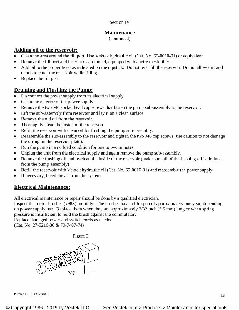
from the pump assembly) Refill the reservoir with Vektek hydraulic oil (Cat. No. 65-0010-01) and reassemble the power supply. If necessary, bleed the air from the system: Electrical Maintenance: All electrical maintenance or repair should be done by a qualified electrician. Inspect the motor brushes (#98S) monthly. The brushes have a life span of approximately one year, depending on power supply use. Replace them when they are approximately 7/32 inch (5.5 mm) long or when spring pressure is insufficient to hold the brush against the commutator. Replace damaged power and switch cords as needed. (Cat. No. 27-5216-30 & 70-7407-74) Figure 3
© Copyright 1986 - 2019 by Vektek, Inc. See Vektek.com > Products > Maintenance for special tools© Copyright 1986 - 2019 by Vektek LLC See Vektek.com > Products > Maintenance for special tools
PL5542 Rev. J, ECN 3708 20
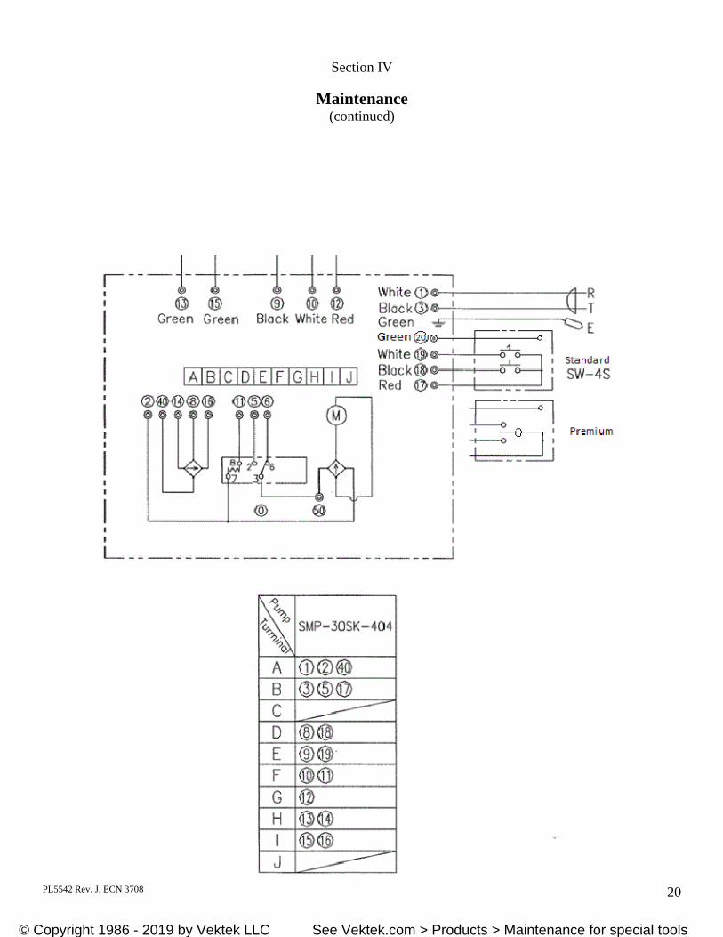
Section IV
Maintenance (continued)
© Copyright 1986 - 2019 by Vektek, Inc. See Vektek.com > Products > Maintenance for special tools© Copyright 1986 - 2019 by Vektek LLC See Vektek.com > Products > Maintenance for special tools
PL5542 Rev. J, ECN 3708 21
Section IV
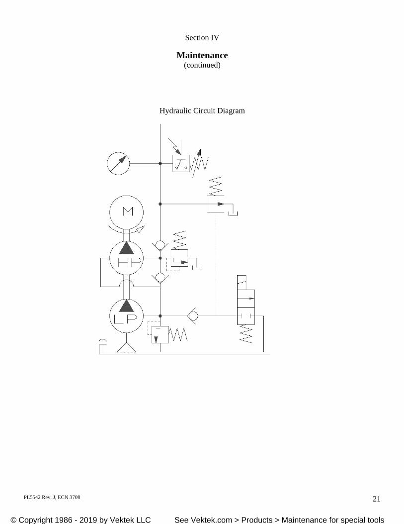
Maintenance (continued)
Hydraulic Circuit Diagram
© Copyright 1986 - 2019 by Vektek, Inc. See Vektek.com > Products > Maintenance for special tools© Copyright 1986 - 2019 by Vektek LLC See Vektek.com > Products > Maintenance for special tools
PL5542 Rev. J, ECN 3708 22
Section IV
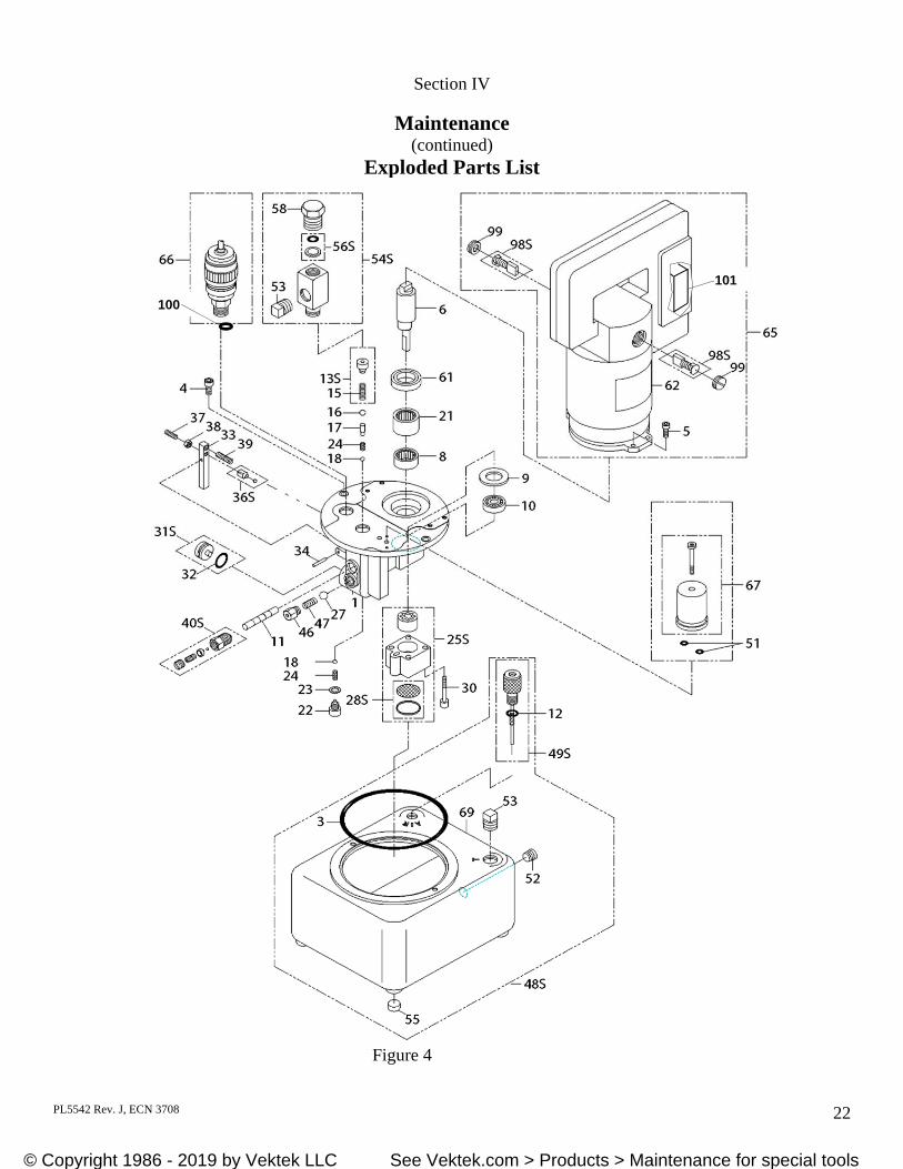
Maintenance (continued)
Exploded Parts List
Figure 4
101
100
© Copyright 1986 - 2019 by Vektek, Inc. See Vektek.com > Products > Maintenance for special tools© Copyright 1986 - 2019 by Vektek LLC See Vektek.com > Products > Maintenance for special tools
PL5542 Rev. J, ECN 3708 23
Section IV
Maintenance (continued)
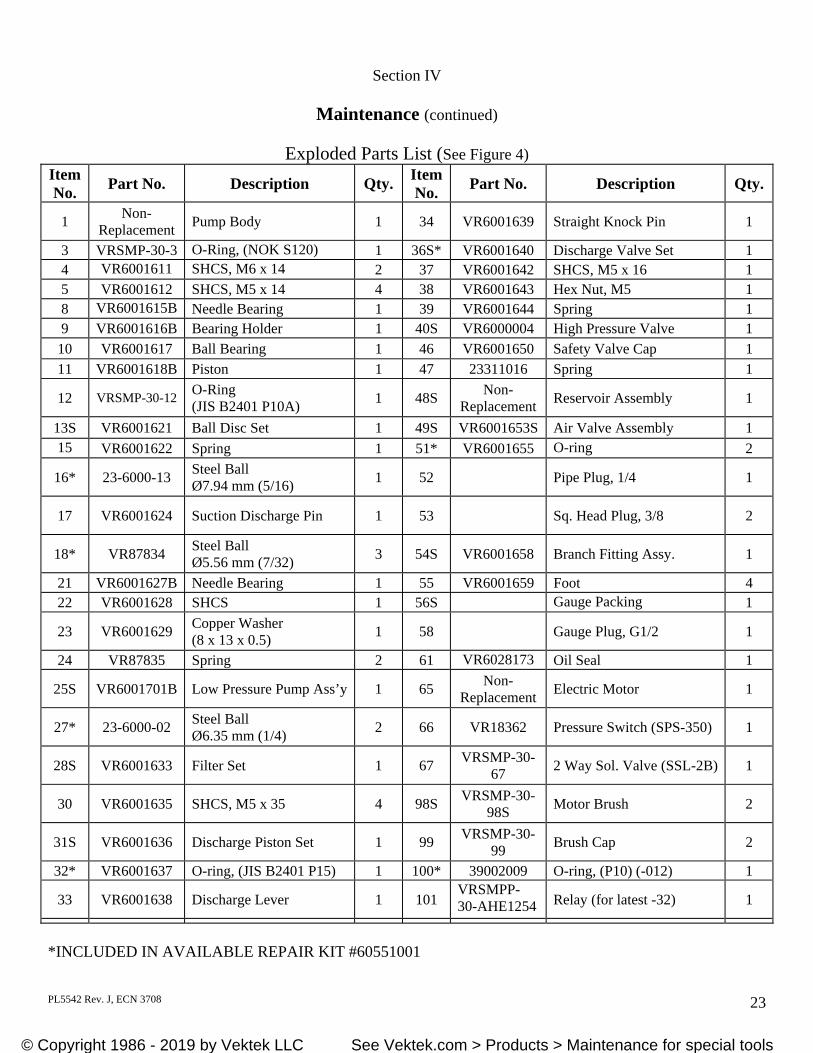
Exploded Parts List (See Figure 4)
*INCLUDED IN AVAILABLE REPAIR KIT #60551001
Item No.
Part No. Description Qty. Item No.
Part No. Description Qty.
1 Non-
Replacement Pump Body 1 34 VR6001639 Straight Knock Pin 1
3 VRSMP-30-3 O-Ring, (NOK S120) 1 36S* VR6001640 Discharge Valve Set 1 4 VR6001611 SHCS, M6 x 14 2 37 VR6001642 SHCS, M5 x 16 1 5 VR6001612 SHCS, M5 x 14 4 38 VR6001643 Hex Nut, M5 1 8 VR6001615B Needle Bearing 1 39 VR6001644 Spring 1 9 VR6001616B Bearing Holder 1 40S VR6000004 High Pressure Valve 1
10 VR6001617 Ball Bearing 1 46 VR6001650 Safety Valve Cap 1
11 VR6001618B Piston 1 47 23311016 Spring 1
12 VRSMP-30-12 O-Ring (JIS B2401 P10A)
1 48S Non-
Replacement Reservoir Assembly 1
13S VR6001621 Ball Disc Set 1 49S VR6001653S Air Valve Assembly 1 15 VR6001622 Spring 1 51* VR6001655 O-ring 2
16* 23-6000-13 Steel Ball Ø7.94 mm (5/16)
1 52 Pipe Plug, 1/4 1
17 VR6001624 Suction Discharge Pin 1 53 Sq. Head Plug, 3/8 2
18* VR87834 Steel Ball Ø5.56 mm (7/32)
3 54S VR6001658 Branch Fitting Assy. 1
21 VR6001627B Needle Bearing 1 55 VR6001659 Foot 4 22 VR6001628 SHCS 1 56S Gauge Packing 1
23 VR6001629 Copper Washer (8 x 13 x 0.5)
1 58 Gauge Plug, G1/2 1
24 VR87835 Spring 2 61 VR6028173 Oil Seal 1
25S VR6001701B Low Pressure Pump Ass’y 1 65 Non-
Replacement Electric Motor 1
27* 23-6000-02 Steel Ball Ø6.35 mm (1/4)
2 66 VR18362 Pressure Switch (SPS-350) 1
28S VR6001633 Filter Set 1 67 VRSMP-30-
67 2 Way Sol. Valve (SSL-2B) 1
30 VR6001635 SHCS, M5 x 35 4 98S VRSMP-30-
98S Motor Brush 2
31S VR6001636 Discharge Piston Set 1 99 VRSMP-30-
99 Brush Cap 2
32* VR6001637 O-ring, (JIS B2401 P15) 1 100* 39002009 O-ring, (P10) (-012) 1
33 VR6001638 Discharge Lever 1 101 VRSMPP-30-AHE1254 Relay (for latest -32) 1
© Copyright 1986 - 2019 by Vektek, Inc. See Vektek.com > Products > Maintenance for special tools© Copyright 1986 - 2019 by Vektek LLC See Vektek.com > Products > Maintenance for special tools
PL5542 Rev. J, ECN 3708 24
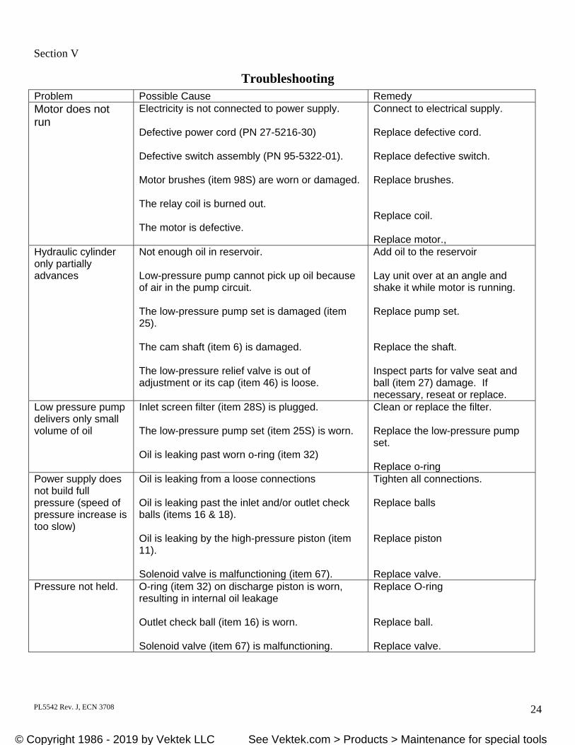
Section V
Troubleshooting
Problem Possible Cause Remedy Motor does not run
Electricity is not connected to power supply. Defective power cord (PN 27-5216-30) Defective switch assembly (PN 95-5322-01). Motor brushes (item 98S) are worn or damaged. The relay coil is burned out. The motor is defective.
Connect to electrical supply. Replace defective cord. Replace defective switch. Replace brushes. Replace coil. Replace motor.,
Hydraulic cylinder only partially advances
Not enough oil in reservoir. Low-pressure pump cannot pick up oil because of air in the pump circuit. The low-pressure pump set is damaged (item 25). The cam shaft (item 6) is damaged. The low-pressure relief valve is out of adjustment or its cap (item 46) is loose.
Add oil to the reservoir Lay unit over at an angle and shake it while motor is running. Replace pump set. Replace the shaft. Inspect parts for valve seat and ball (item 27) damage. If necessary, reseat or replace.
Low pressure pump delivers only small volume of oil
Inlet screen filter (item 28S) is plugged. The low-pressure pump set (item 25S) is worn. Oil is leaking past worn o-ring (item 32)
Clean or replace the filter. Replace the low-pressure pump set. Replace o-ring
Power supply does not build full pressure (speed of pressure increase is too slow)
Oil is leaking from a loose connections Oil is leaking past the inlet and/or outlet check balls (items 16 & 18). Oil is leaking by the high-pressure piston (item 11). Solenoid valve is malfunctioning (item 67).
Tighten all connections. Replace balls Replace piston Replace valve.
Pressure not held. O-ring (item 32) on discharge piston is worn, resulting in internal oil leakage Outlet check ball (item 16) is worn. Solenoid valve (item 67) is malfunctioning.
Replace O-ring Replace ball. Replace valve.
© Copyright 1986 - 2019 by Vektek, Inc. See Vektek.com > Products > Maintenance for special tools© Copyright 1986 - 2019 by Vektek LLC See Vektek.com > Products > Maintenance for special tools
PL5542 Rev. J, ECN 3708 25
Section V
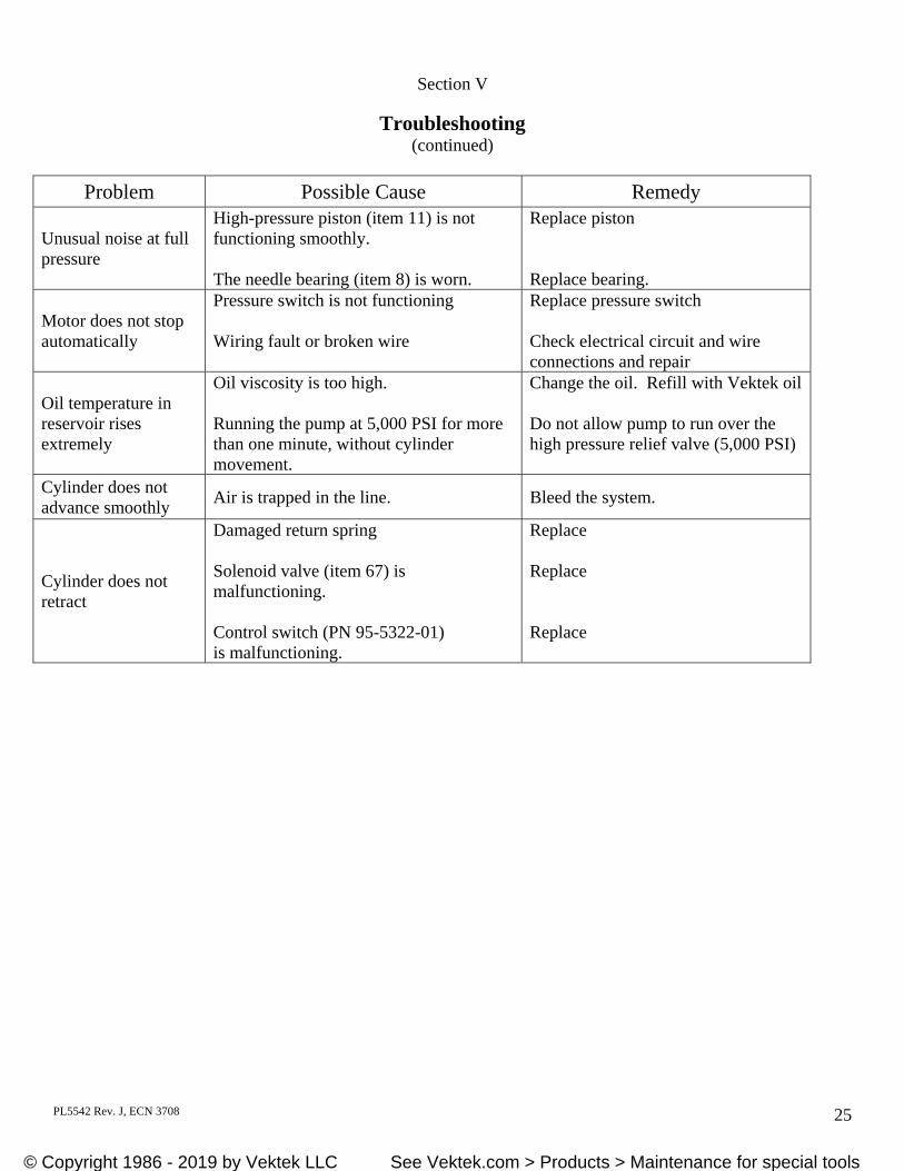
Troubleshooting (continued)
Problem Possible Cause Remedy
Unusual noise at full pressure
High-pressure piston (item 11) is not functioning smoothly. The needle bearing (item 8) is worn.
Replace piston Replace bearing.
Motor does not stop automatically
Pressure switch is not functioning Wiring fault or broken wire
Replace pressure switch Check electrical circuit and wire connections and repair
Oil temperature in reservoir rises extremely
Oil viscosity is too high. Running the pump at 5,000 PSI for more than one minute, without cylinder movement.
Change the oil. Refill with Vektek oil Do not allow pump to run over the high pressure relief valve (5,000 PSI)
Cylinder does not advance smoothly
Air is trapped in the line. Bleed the system.
Cylinder does not retract
Damaged return spring Solenoid valve (item 67) is malfunctioning. Control switch (PN 95-5322-01) is malfunctioning.
Replace Replace Replace
© Copyright 1986 - 2019 by Vektek, Inc. See Vektek.com > Products > Maintenance for special tools© Copyright 1986 - 2019 by Vektek LLC See Vektek.com > Products > Maintenance for special tools
PL5542 Rev. J, ECN 3708 26
Section VI
Warranty and Return Information Warranty: Vektek, Inc. warrants each VektorFlo product to the original purchaser unless end user assignment is made at the time of purchase. Each device is warranted against defects in workmanship and materials for one year from the date of delivery. This warranty is limited to the repair or replacement of any part or parts which are found by Vektek to be defective and does not cover ordinary wear and tear, abuse, misapplication, overloading, excessive flow rates, altered products or the use of improper fluids. This warranty is the only warranty covering VektorFlo products. There are no other warranties covering VektorFlo products, either expressed or implied. Vektek, Inc. specifically disclaims any warranty of merchantability or fitness for a particular purpose. When the question of warranty arises, the user must contact the factory for permission to return the merchandise. All returned merchandise must be addressed to a Return Authorization number and shipped to the address indicated on the RA. Returns: All returns are subject to a progressive restocking fee. There is a $25.00 minimum restocking fee on any return. All returns must be pre-authorized, please call for Return Authorization number. Any return not sent to a specific RA number will be treated as scrap. Transportation is to be prepaid and the evidence of delivery date furnished.
© Copyright 1986 - 2019 by Vektek, Inc. See Vektek.com > Products > Maintenance for special tools© Copyright 1986 - 2019 by Vektek LLC See Vektek.com > Products > Maintenance for special tools