12.13 (ATA 32) LANDING GEAR 12.13.1 · PDF file- lights can be tested using CAUT / ADVSY...
43
12.13 (ATA 32) LANDING GEAR 12.13.1 Introduction The Dash 8-Q400 landing gear is electrically controlled and hydraulically operated. Hydraulically operated nosewheel steering gives directional control during taxiing, take-off and landing. Each main wheel has hydraulically powered anti-skid brakes. There is also an emergency/park brake system. 12.13.2 General The tricycle gear is a retractable dual wheel installation. The main gears retract aft into the nacelles and the nose gear retracts forward into the nose section. Doors completely enclose the landing gear when it is retracted and partially enclose the gear when it is down. A Power Transfer Unit (PTU) supplies back-up hydraulic power to the No. 2 hydraulic system. If the landing gear cannot be extended normally, there is an alternate landing gear extension method. Advisory lights show position of gear doors and downlocks. There is also an alternate downlock verification system. An aural warning sounds if the gear is not extended during certain landing configurations. A Proximity Sensor Electronics Unit (PSEU) monitors and controls the operation of the landing gear components. The nosewheels are steerable by a flight deck hand control and by the rudder pedals. The wheels may be equipped (customer option) with tire fill pressure gauges for quick visual means of verifying tire pressure during aircraft walk-around. The main wheels are equipped with anti skid multiple disc brakes. The brakes can be controlled by the brake pedals or the EMERG BRAKE lever. Dash8 - Q400 - Landing Gear Page 1
-
Upload
trinhthuan -
Category
Documents
-
view
226 -
download
3
Transcript of 12.13 (ATA 32) LANDING GEAR 12.13.1 · PDF file- lights can be tested using CAUT / ADVSY...
12.13 (ATA 32) LANDING GEAR
12.13.1 Introduction
The Dash 8-Q400 landing gear is electrically controlled and hydraulically operated. Hydraulicallyoperated nosewheel steering gives directional control during taxiing, take-off and landing. Eachmain wheel has hydraulically powered anti-skid brakes. There is also an emergency/park brakesystem.
12.13.2 General
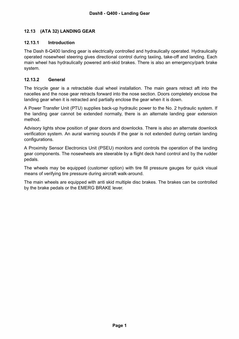
The tricycle gear is a retractable dual wheel installation. The main gears retract aft into thenacelles and the nose gear retracts forward into the nose section. Doors completely enclose thelanding gear when it is retracted and partially enclose the gear when it is down.
A Power Transfer Unit (PTU) supplies back-up hydraulic power to the No. 2 hydraulic system. Ifthe landing gear cannot be extended normally, there is an alternate landing gear extensionmethod.
Advisory lights show position of gear doors and downlocks. There is also an alternate downlockverification system. An aural warning sounds if the gear is not extended during certain landingconfigurations.
A Proximity Sensor Electronics Unit (PSEU) monitors and controls the operation of the landinggear components. The nosewheels are steerable by a flight deck hand control and by the rudderpedals.
The wheels may be equipped (customer option) with tire fill pressure gauges for quick visualmeans of verifying tire pressure during aircraft walk-around.
The main wheels are equipped with anti skid multiple disc brakes. The brakes can be controlledby the brake pedals or the EMERG BRAKE lever.
Dash8 - Q400 - Landing Gear
Page 1
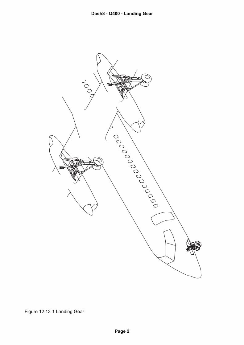
Figure 12.13-1 Landing Gear
Dash8 - Q400 - Landing Gear
Page 2
12.13.3 Controls and Indications - Landing Gear and Brakes
Dash8 - Q400 - Landing Gear
Page 3
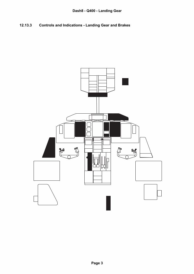
Figure 12.13-2 Nose Gear Ground Lock Control Handle
PRESS BUTTONTO RELEASEPULL AND TURNTO GROUND LOCKNOSE GEAR
PR
ES
S B
UT
TO
NT
O R
EL
EA
SE
PU
LL
AN
D T
UR
NT
O G
RO
UN
D L
OC
KN
OS
E G
EA
R
1 2
1 2
ENGAGED(FULLY EXTENDED)
DISENGAGED(FULLY RETRACTED)
Dash8 - Q400 - Landing Gear
Page 4
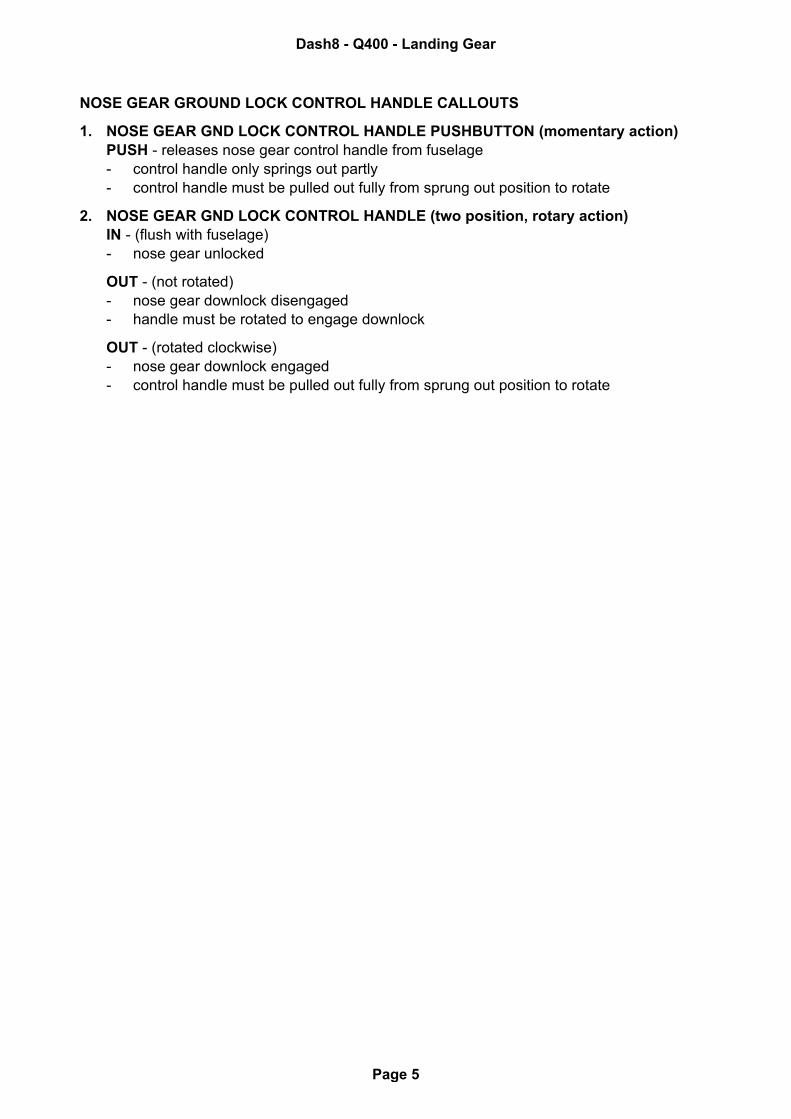
NOSE GEAR GROUND LOCK CONTROL HANDLE CALLOUTS
1. NOSE GEAR GND LOCK CONTROL HANDLE PUSHBUTTON (momentary action)PUSH - releases nose gear control handle from fuselage- control handle only springs out partly- control handle must be pulled out fully from sprung out position to rotate
2. NOSE GEAR GND LOCK CONTROL HANDLE (two position, rotary action)IN - (flush with fuselage)- nose gear unlocked
OUT - (not rotated)- nose gear downlock disengaged- handle must be rotated to engage downlock
OUT - (rotated clockwise)- nose gear downlock engaged- control handle must be pulled out fully from sprung out position to rotate
Dash8 - Q400 - Landing Gear
Page 5
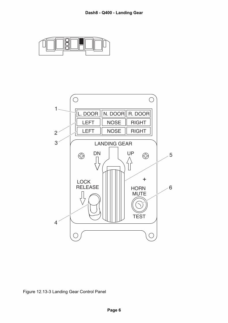
Figure 12.13-3 Landing Gear Control Panel
LANDING GEAR
LOCKRELEASE
DN UP
TEST
MUTEHORN
N. DOORL. DOOR R. DOOR
RIGHTNOSELEFT
RIGHTNOSELEFT
1
2
4
5
3
6
Dash8 - Q400 - Landing Gear
Page 6
LANDING GEAR CONTROL PANEL CALLOUTS
1. GEAR DOOR ADVISORY LIGHTS
(L. DOOR, N. DOOR, R. DOOR) segment (amber) - related hydraulic gear door open- hydraulic gear doors stay open with no hydraulic pressure
(L. DOOR, N. DOOR, R. DOOR) segment (blank) - related hydraulic gear door closed- hydraulic gear doors close after normal gear extension and retraction
2. LANDING GEAR SAFE ADVISORY LIGHTS
LEFT, NOSE, RIGHT segment (green) - related gear down and locked- lights can be tested using CAUT / ADVSY LIGHTS toggle switch- gear can also be checked with downlock verification lights
LEFT, NOSE, RIGHT segment (blank)- related gear not down and locked or in uplock position
3. LANDING GEAR UNSAFE ADVISORY LIGHTS
LEFT, NOSE, RIGHT segment (red) - related gear not locked up or down
LEFT, NOSE, RIGHT segment (blank ) - related gear locked up or down or no power to lights
4. SELECTOR LEVER LOCK BUTTON (momentary action)PUSH DOWN AND HOLD - enables operation of landing gear handle
5. LANDING GEAR SELECTOR LEVER/LIGHT (two position)
UP - starts landing gear retraction sequence
DN - starts normal landing gear extension sequence- also select DN for alternate gear extension- No Smoking signs come on automatically if not on
HANDLE (amber)- landing gear operation does not agree with position of landing gear selector handle
6. LANDING GEAR WARNING HORN MUTE/TEST SWITCH (two position, momentary action)
TEST - gear warning tone sounds over flight deck speakers
HORN MUTE - gear warning tone is silenced under certain configurations
Dash8 - Q400 - Landing Gear
Page 7
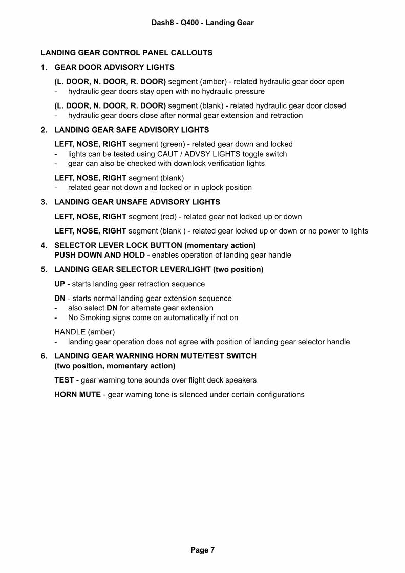
Figure 12.13-4 Landing Gear Alternate Release Door and Inhibit Switch
ARE CLEAR OF OBSTRUCTIONSBEFORE CLOSING ACCESS PANEL
ENSURE ALL WHEEL WELLS
TO CLOSE DUMP VALVE
CAUTION
LANDING GEAR
ALTERNATE RELEASE
OPEN DOOR FULLY
INHIBIT
NORMAL
DOOR OPENDOOR CLOSED
1
A
A
INHIBIT
NORMAL
3
2
Dash8 - Q400 - Landing Gear
Page 8
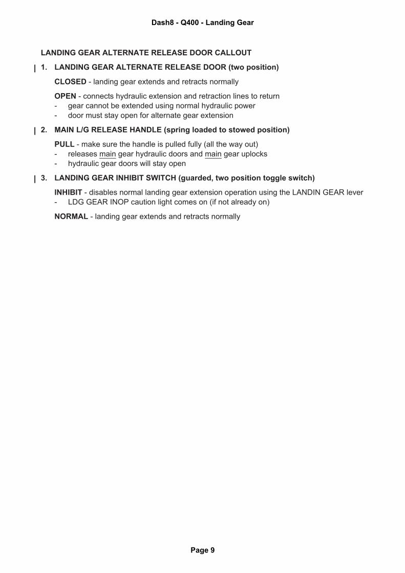
LANDING GEAR ALTERNATE RELEASE DOOR CALLOUT
1. LANDING GEAR ALTERNATE RELEASE DOOR (two position)
CLOSED - landing gear extends and retracts normally
OPEN - connects hydraulic extension and retraction lines to return
- gear cannot be extended using normal hydraulic power
- door must stay open for alternate gear extension
2. MAIN L/G RELEASE HANDLE (spring loaded to stowed position)
PULL - make sure the handle is pulled fully (all the way out)
- releases main gear hydraulic doors and main gear uplocks
- hydraulic gear doors will stay open
3. LANDING GEAR INHIBIT SWITCH (guarded, two position toggle switch)
INHIBIT - disables normal landing gear extension operation using the LANDIN GEAR lever
- LDG GEAR INOP caution light comes on (if not already on)
NORMAL - landing gear extends and retracts normally
Dash8 - Q400 - Landing Gear
Page 9
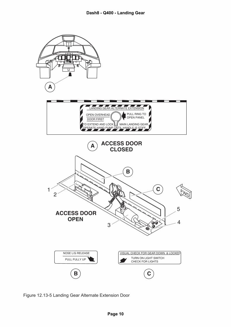
Figure 12.13-5 Landing Gear Alternate Extension Door
LANDING GEAR ALTERNATE EXTENSION
OPEN OVERHEAD
DOOR FIRST
PULL RING TOOPEN PANEL
TO EXTEND AND LOCK MAIN LANDING GEAR,OPERATE HAND PUMP UNTIL HANDLE IS STIFF.
NOSE L/G RELEASE
PULL FULLY UP
VISUAL CHECK FOR GEAR DOWN & LOCKED
TURN ON LIGHT SWITCHCHECK FOR LIGHTS
ACCESS DOOROPEN
ACCESS DOORCLOSED
5
4
1 FWD
A
A
B
C
B C
3
2
5
4
Dash8 - Q400 - Landing Gear
Page 10
LANDING GEAR ALTERNATE EXTENSION DOOR CALLOUTS
1. LANDING GEAR ALTERNATE EXTENSION DOOR (two position)
CLOSED - landing gear extends and retracts normally
OPEN - alternate extension hydraulic fluid available for alternate gear extension- door must stay open for alternate gear extension
2. NOSE GEAR RELEASE HANDLE (spring loaded to stowed position)
PULL - make sure the handle is pulled fully (all the way out)- releases nose gear doors and nose gear uplocks- hydraulic gear doors will stay open
3. MAIN GEAR ALTERNATE EXTENSION HAND PUMP (two position)- pumps fluid from the emergency hydraulic reservoir to the auxiliary main landing gear
actuators- handle located behind copilot's seat is inserted into socket
4. LANDING GEAR DOWNLOCK VERIFICATION SWITCH (two position, toggle switch)
AFT - activates alternate downlock verification system on each gear- enables operation of gear verification lights
CENTER - alternate downlock verification system deactivated
5. LANDING GEAR DOWNLOCK VERIFICATION LIGHTS(NG, LH, RH) (green)- related (Nose, Left main, Right main) landing gear is down and locked using the alter-
nate downlock verification system- downlock verification toggle switch must be set aft
(NG, LH, RH) - (blank)- related (Nose, Left main, Right main) landing gear is not down and locked using the
alternate downlock verification system- downlock verification toggle switch not set aft
Dash8 - Q400 - Landing Gear
Page 11
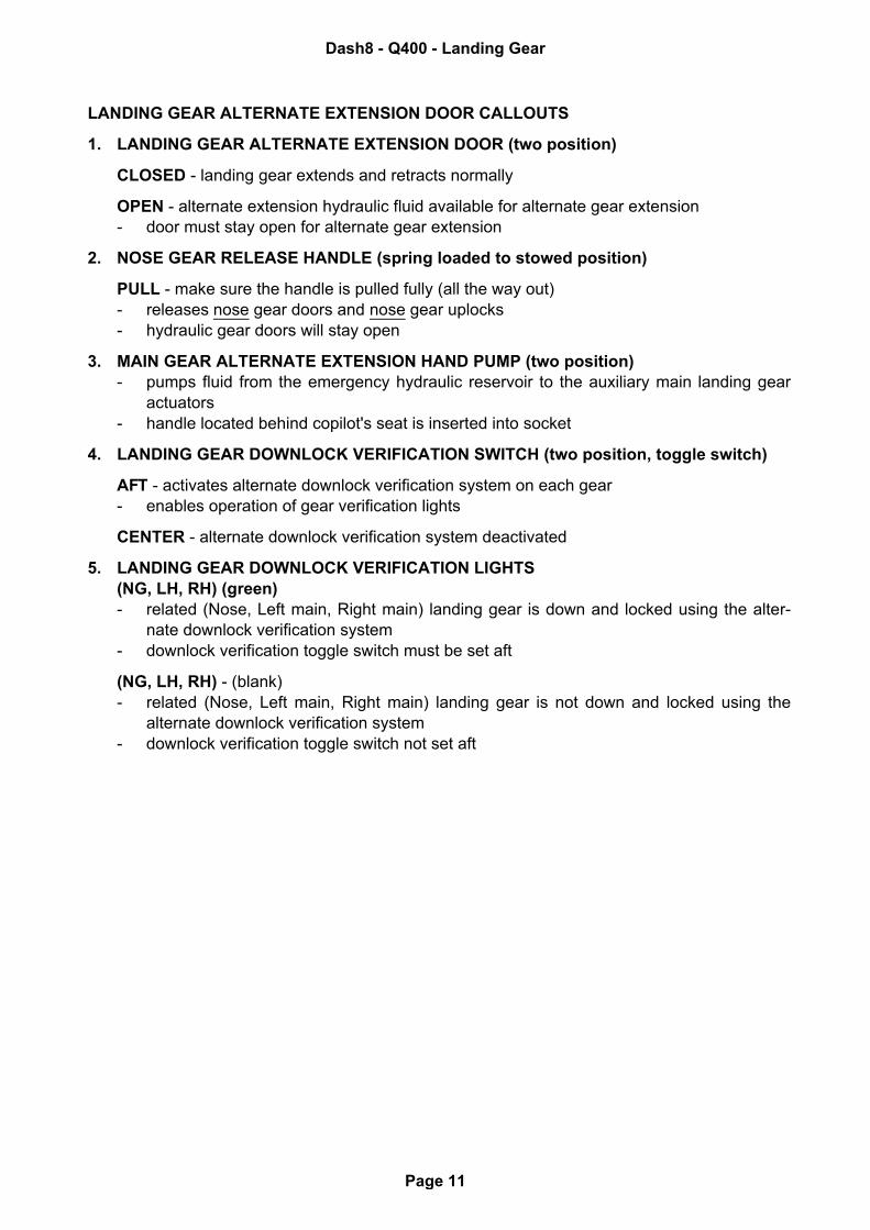
Figure 12.13-6 Anti Skid Switch
C-FJOE
1
Dash8 - Q400 - Landing Gear
Page 12
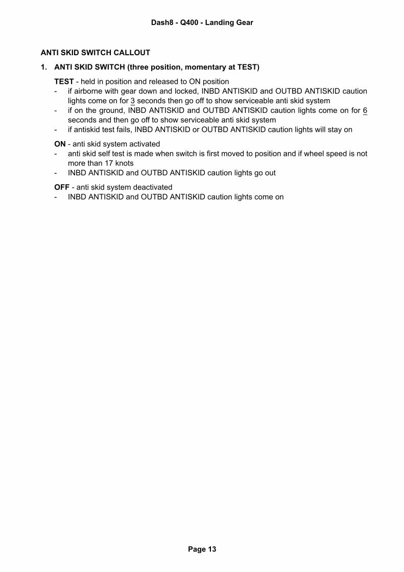
ANTI SKID SWITCH CALLOUT
1. ANTI SKID SWITCH (three position, momentary at TEST)
TEST - held in position and released to ON position- if airborne with gear down and locked, INBD ANTISKID and OUTBD ANTISKID caution
lights come on for 3 seconds then go off to show serviceable anti skid system- if on the ground, INBD ANTISKID and OUTBD ANTISKID caution lights come on for 6
seconds and then go off to show serviceable anti skid system- if antiskid test fails, INBD ANTISKID or OUTBD ANTISKID caution lights will stay on
ON - anti skid system activated- anti skid self test is made when switch is first moved to position and if wheel speed is not
more than 17 knots- INBD ANTISKID and OUTBD ANTISKID caution lights go out
OFF - anti skid system deactivated- INBD ANTISKID and OUTBD ANTISKID caution lights come on
Dash8 - Q400 - Landing Gear
Page 13
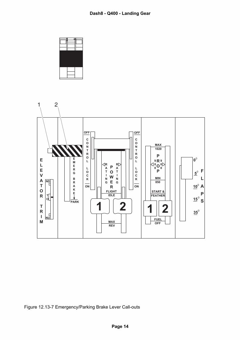
Figure 12.13-7 Emergency/Parking Brake Lever Call-outs
PROP F
L
A
P
S
900
900
MAX1020
MIN850
START &FEATHER
FUELOFF
0
5
10
15
351 2
0
0
0
0
0
CONTROL
LOCK
RATING
P
ER
EMERG
BRAKE
ELEVATOR
TRIM
TO
RATING
CONTROL
LOCK
FLIGHTIDLE
MAXREV
PARK
ND
NU
OFF
ON
1 2
OFF
ON
WO
21
Dash8 - Q400 - Landing Gear
Page 14
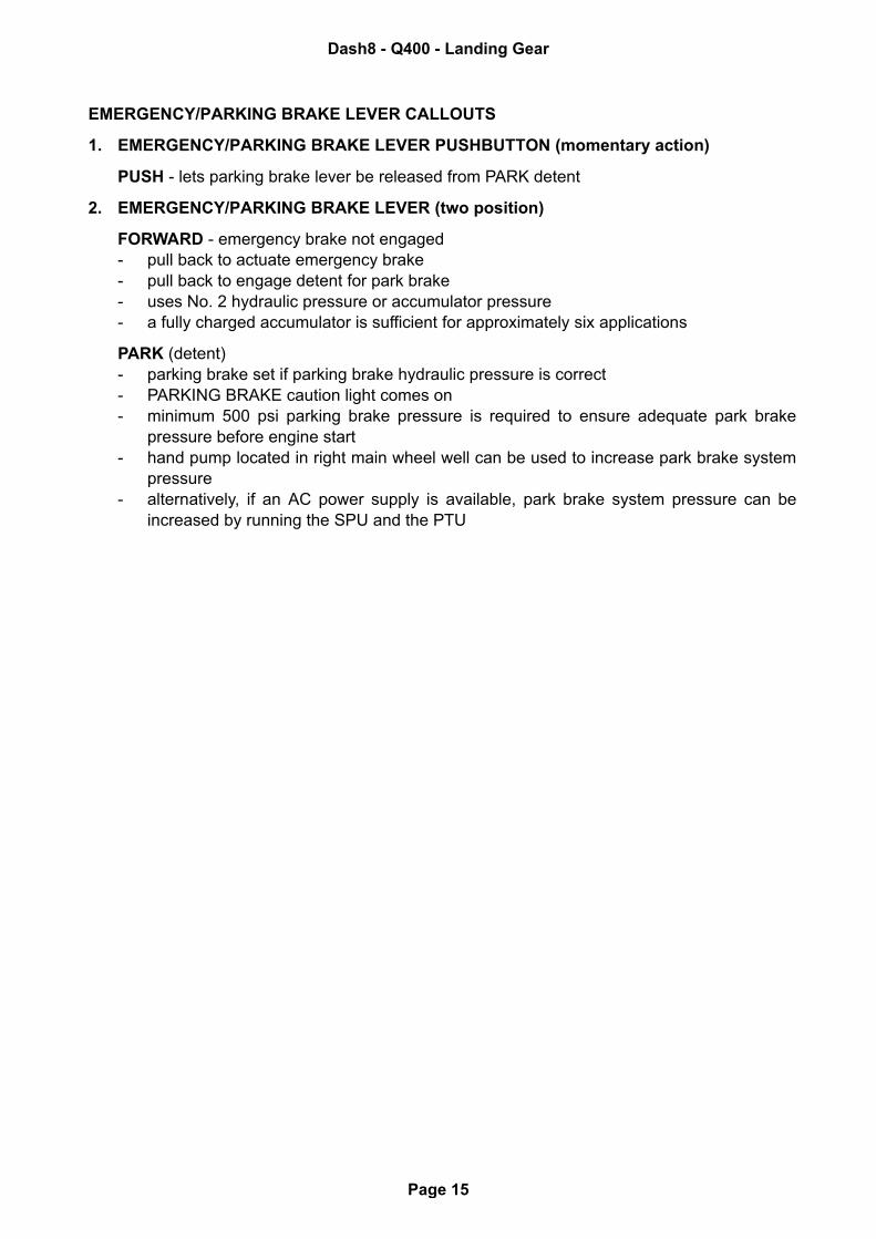
EMERGENCY/PARKING BRAKE LEVER CALLOUTS
1. EMERGENCY/PARKING BRAKE LEVER PUSHBUTTON (momentary action)
PUSH - lets parking brake lever be released from PARK detent
2. EMERGENCY/PARKING BRAKE LEVER (two position)
FORWARD - emergency brake not engaged- pull back to actuate emergency brake- pull back to engage detent for park brake- uses No. 2 hydraulic pressure or accumulator pressure- a fully charged accumulator is sufficient for approximately six applications
PARK (detent)- parking brake set if parking brake hydraulic pressure is correct- PARKING BRAKE caution light comes on- minimum 500 psi parking brake pressure is required to ensure adequate park brake
pressure before engine start- hand pump located in right main wheel well can be used to increase park brake system
pressure- alternatively, if an AC power supply is available, park brake system pressure can be
increased by running the SPU and the PTU
Dash8 - Q400 - Landing Gear
Page 15
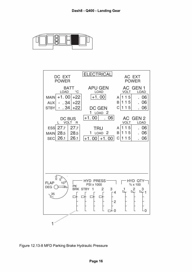
Figure 12.13-8 MFD Parking Brake Hydraulic Pressure
27.728.5
27.728.526.126.1
ELECTRICAL AC EXTPOWER
DC EXTPOWER
LOAD
1 1 51 1 51 1 5
. 06
. 06
. 06
1 1 51 1 51 1 5
. 06
. 06
. 06
AB
C
AB
C
+22+22+22
+1. 00- . 34- . 34
+1. 00
+1. 00 . 06
+1. 00 +1. 00
APU GEN
DC GENLOAD1 2
TRULOAD1 2
LOADBATT
°C
VOLTDC BUS
RL
MAIN
AUXSTBY
ESS
MAINSEC
AC GEN 1
AC GEN 2
VOLT LOAD
VOLT LOAD
HYD PRESS HYD QTYPK
STBYPSI x 1000 % x 100
BRK 1 2 3 1 2 34
2
FLAPDEG
1050
35
0 0
1
Dash8 - Q400 - Landing Gear
Page 16
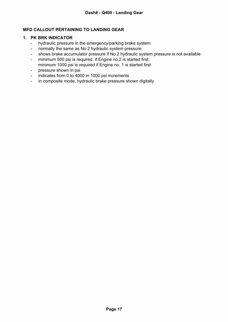
MFD CALLOUT PERTAINING TO LANDING GEAR
1. PK BRK INDICATOR - hydraulic pressure in the emergency/parking brake system- normally the same as No 2 hydraulic system pressure- shows brake accumulator pressure if No 2 hydraulic system pressure is not available- minimum 500 psi is required if Engine no.2 is started first
minimum 1000 psi is required if Engine no. 1 is started first- pressure shown in psi- indicates from 0 to 4000 in 1000 psi increments- in composite mode, hydraulic brake pressure shown digitally
Dash8 - Q400 - Landing Gear
Page 17
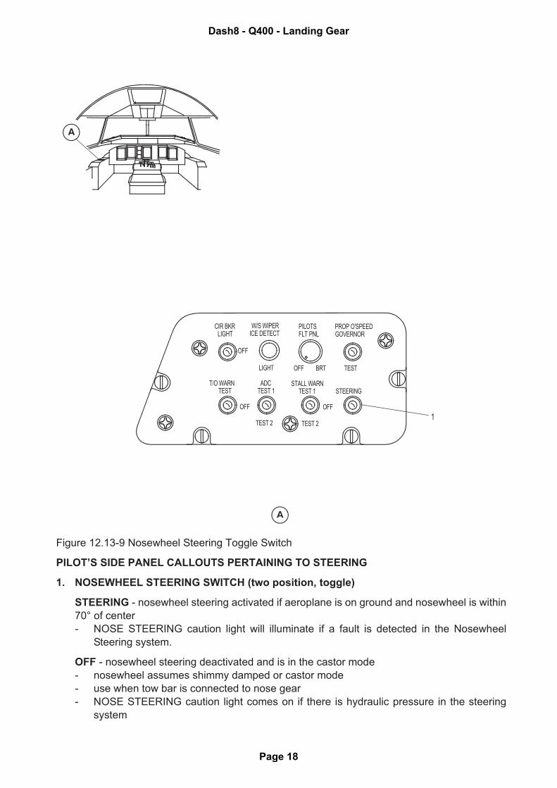
Figure 12.13-9 Nosewheel Steering Toggle Switch
PILOT’S SIDE PANEL CALLOUTS PERTAINING TO STEERING
1. NOSEWHEEL STEERING SWITCH (two position, toggle)
STEERING - nosewheel steering activated if aeroplane is on ground and nosewheel is within
70° of center
- NOSE STEERING caution light will illuminate if a fault is detected in the Nosewheel
Steering system.
OFF - nosewheel steering deactivated and is in the castor mode
- nosewheel assumes shimmy damped or castor mode
- use when tow bar is connected to nose gear
- NOSE STEERING caution light comes on if there is hydraulic pressure in the steering
system
CIR BKR LIGHT
W/S WIPERICE DETECT
PILOTSFLT PNL
PROP O'SPEEDGOVERNOR
OFF
LIGHT
ADCTEST 1
TEST 2 TEST 2
OFF BRT
STALL WARN TEST 1
OFF
STEERING
OFF
TEST
T/O WARNTEST
1
Dash8 - Q400 - Landing Gear
Page 18
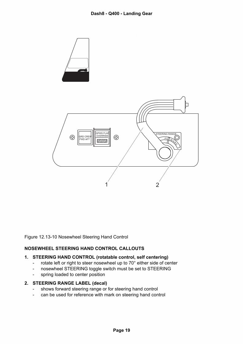
Figure 12.13-10 Nosewheel Steering Hand Control
NOSEWHEEL STEERING HAND CONTROL CALLOUTS
1. STEERING HAND CONTROL (rotatable control, self centering)- rotate left or right to steer nosewheel up to 70° either side of center- nosewheel STEERING toggle switch must be set to STEERING- spring loaded to center position
2. STEERING RANGE LABEL (decal)- shows forward steering range or for steering hand control- can be used for reference with mark on steering hand control
GRD CREW FWD AFT
GPWS FLAP OVERRIDE
F W ARD
OR
STEERING RANGE
1 2
Dash8 - Q400 - Landing Gear
Page 19
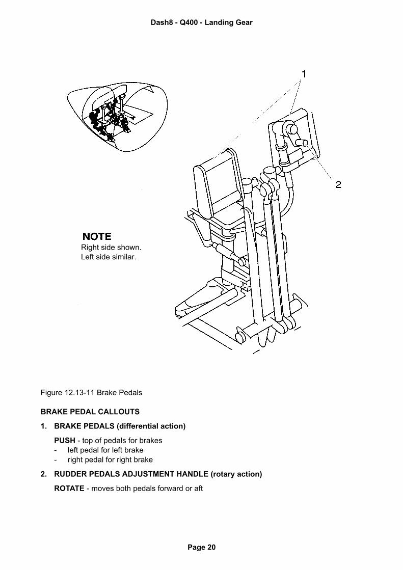
Figure 12.13-11 Brake Pedals
BRAKE PEDAL CALLOUTS
1. BRAKE PEDALS (differential action)
PUSH - top of pedals for brakes- left pedal for left brake- right pedal for right brake
2. RUDDER PEDALS ADJUSTMENT HANDLE (rotary action)
ROTATE - moves both pedals forward or aft
Right side shown. Left side similar.
Dash8 - Q400 - Landing Gear
Page 20
12.13.4 Landing Gear - Description
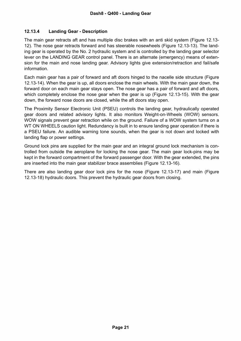
The main gear retracts aft and has multiple disc brakes with an anti skid system (Figure 12.13-12). The nose gear retracts forward and has steerable nosewheels (Figure 12.13-13). The land-ing gear is operated by the No. 2 hydraulic system and is controlled by the landing gear selectorlever on the LANDING GEAR control panel. There is an alternate (emergency) means of exten-sion for the main and nose landing gear. Advisory lights give extension/retraction and fail/safeinformation.
Each main gear has a pair of forward and aft doors hinged to the nacelle side structure (Figure12.13-14). When the gear is up, all doors enclose the main wheels. With the main gear down, theforward door on each main gear stays open. The nose gear has a pair of forward and aft doors,which completely enclose the nose gear when the gear is up (Figure 12.13-15). With the geardown, the forward nose doors are closed, while the aft doors stay open.
The Proximity Sensor Electronic Unit (PSEU) controls the landing gear, hydraulically operatedgear doors and related advisory lights. It also monitors Weight-on-Wheels (WOW) sensors.WOW signals prevent gear retraction while on the ground. Failure of a WOW system turns on aWT ON WHEELS caution light. Redundancy is built in to ensure landing gear operation if there isa PSEU failure. An audible warning tone sounds, when the gear is not down and locked withlanding flap or power settings.
Ground lock pins are supplied for the main gear and an integral ground lock mechanism is con-trolled from outside the aeroplane for locking the nose gear. The main gear lock-pins may bekept in the forward compartment of the forward passenger door. With the gear extended, the pinsare inserted into the main gear stabilizer brace assemblies (Figure 12.13-16).
There are also landing gear door lock pins for the nose (Figure 12.13-17) and main (Figure12.13-18) hydraulic doors. This prevent the hydraulic gear doors from closing.
Dash8 - Q400 - Landing Gear
Page 21
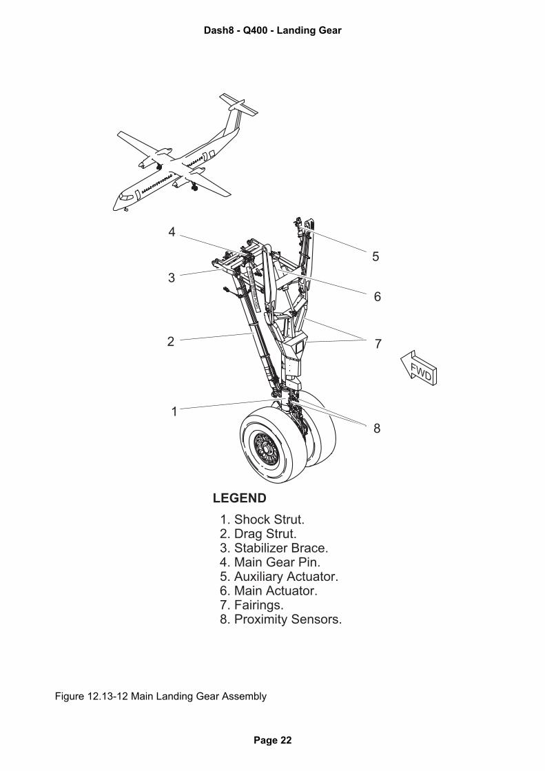
Figure 12.13-12 Main Landing Gear Assembly
RE
MO
VE
BE
FO
RE
FL
IGH
T
LEGEND
1. Shock Strut. 2. Drag Strut. 3. Stabilizer Brace. 4. Main Gear Pin. 5. Auxiliary Actuator. 6. Main Actuator. 7. Fairings. 8. Proximity Sensors.
FWD
1
2
3
4
5
6
7
8
Dash8 - Q400 - Landing Gear
Page 22
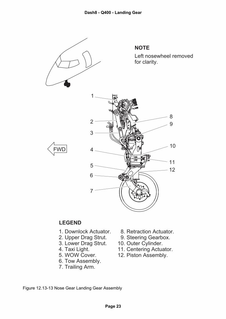
Figure 12.13-13 Nose Gear Landing Gear Assembly
11
12
FWD
1
2
3
4
5
6
7
NOTE
Left nosewheel removedfor clarity.
LEGEND
1. Downlock Actuator. 2. Upper Drag Strut. 3. Lower Drag Strut. 4. Taxi Light. 5. WOW Cover. 6. Tow Assembly. 7. Trailing Arm.
8. Retraction Actuator. 9. Steering Gearbox.10. Outer Cylinder.11. Centering Actuator.12. Piston Assembly.
10
8
9
Dash8 - Q400 - Landing Gear
Page 23
Figure 12.13-14 Main Landing Gear Extended Doors Open
NOTE
Left gear shown.Right gear similar.
FWD
Dash8 - Q400 - Landing Gear
Page 24
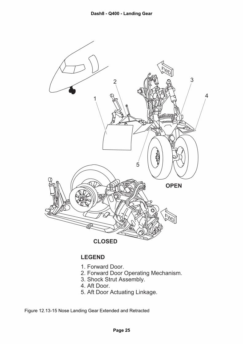
Figure 12.13-15 Nose Landing Gear Extended and Retracted
FWD
FWD
CLOSED
OPEN
1
5
2 3
4
LEGEND
1. Forward Door.2. Forward Door Operating Mechanism.3. Shock Strut Assembly.4. Aft Door.5. Aft Door Actuating Linkage.
Dash8 - Q400 - Landing Gear
Page 25
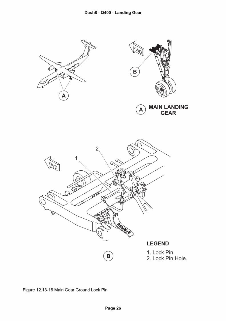
Figure 12.13-16 Main Gear Ground Lock Pin
A
A
MAIN LANDINGGEAR
B
B
2
1
LEGEND
1. Lock Pin.2. Lock Pin Hole.
FWD
FWD
Dash8 - Q400 - Landing Gear
Page 26
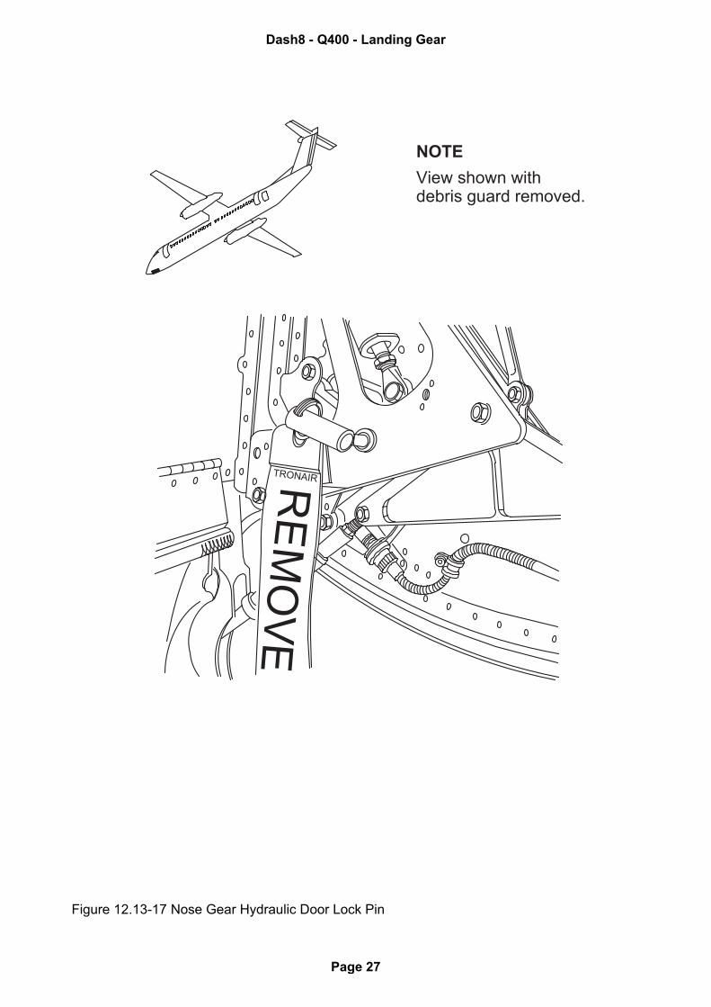
Figure 12.13-17 Nose Gear Hydraulic Door Lock Pin
TRONAIRRE
MO
VE
NOTE
View shown with debris guard removed.
Dash8 - Q400 - Landing Gear
Page 27
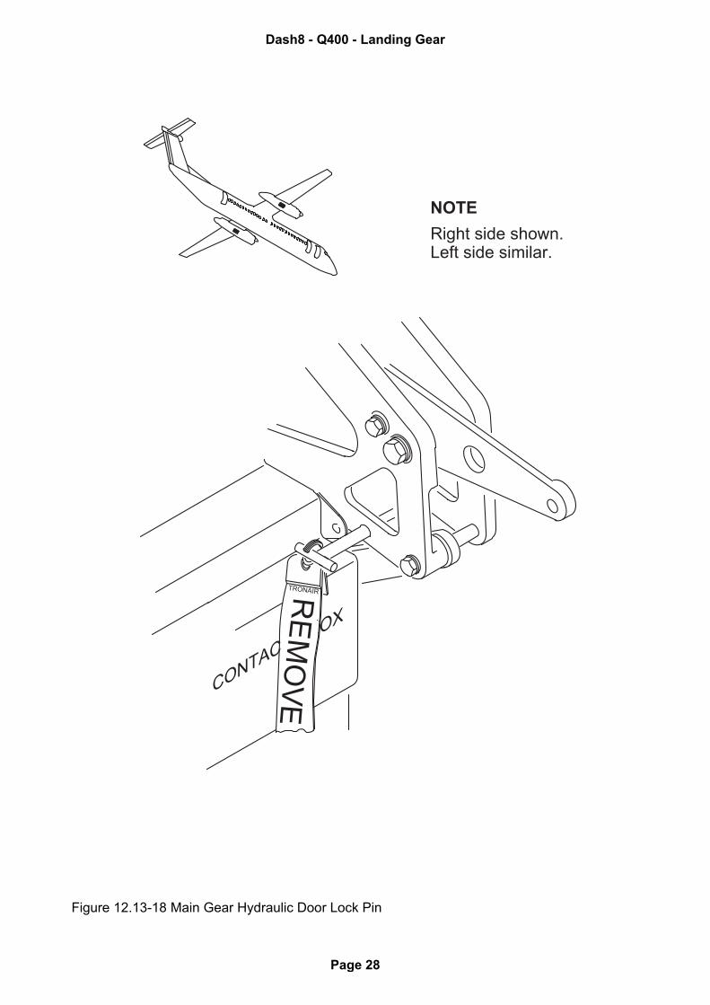
Figure 12.13-18 Main Gear Hydraulic Door Lock Pin
TRONAIRRO
VECONTAC
OXEM
NOTE
Right side shown.Left side similar.
Dash8 - Q400 - Landing Gear
Page 28
12.13.4.1 Gear Operation
Landing gear operation is controlled and monitored from the LANDING GEAR control panel,adjacent the Engine Display (ED). The landing gear is selected UP or DN (down) by moving thelanding gear selector lever. A LOCK RELEASE selector lever must be held down to let the gearselector lever move in either direction.
An alternate downlock verification system confirms downlock engagement if the primary down-lock indication is in doubt. Three green downlock verification lights are located under the LAND-ING GEAR ALTERNATE EXTENSION panel in the flight deck floor.
Gear Warning Tone
A landing gear warning tone sounds over the flight compartment speakers if the HORN switch isheld at TEST. It also sounds if the gear is not down and locked and:
1. • flaps > 8.5°• either engine torque < 50%• both PLA < RATING detent
2. • both PLA < FLIGHT IDLE +12°• KIAS < 156
• RA < 1053 ft (321 m) if it is valid
3. • one PLA < FLIGHT IDLE + 12°• both PLA < RATING detent• HORN switch not latched at MUTE• KIAS < 156 • RA < 1053 ft (321 m) if it is valid
NOTE: This is the only case in which the landing gear warning tone may be muted. Enginefailure at airspeed less than 156 KIAS.
Dash8 - Q400 - Landing Gear
Page 29
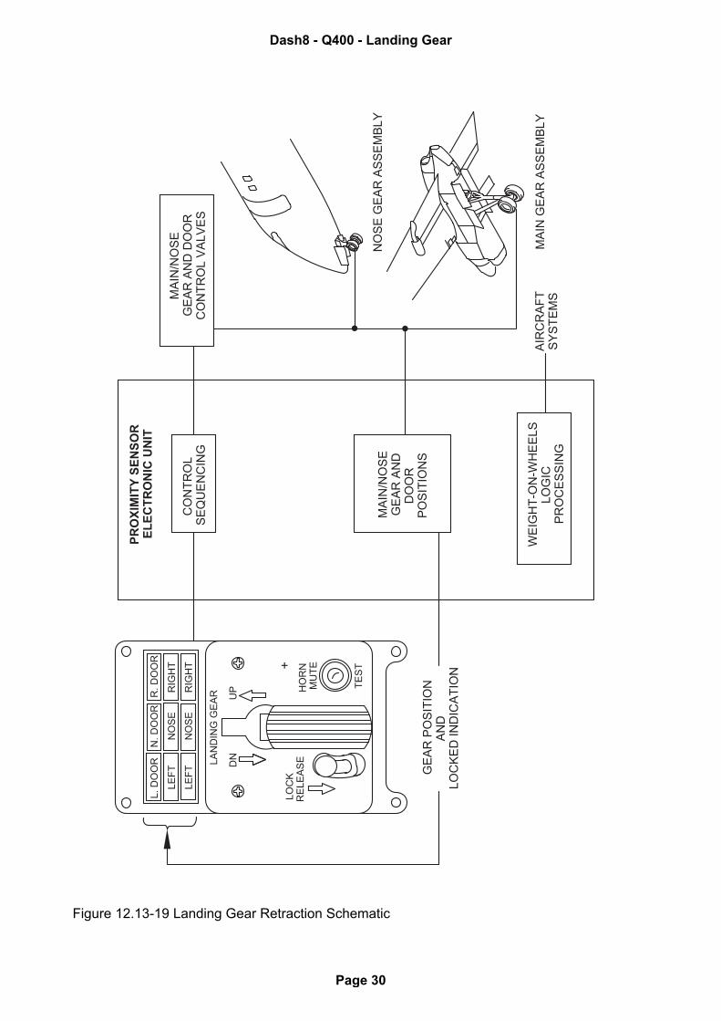
Figure 12.13-19 Landing Gear Retraction Schematic
CO
NT
RO
LS
EQ
UE
NC
ING
MA
IN/N
OS
EG
EA
R A
ND
DO
OR
PO
SIT
ION
S
WE
IGH
T-O
N-W
HE
ELS
LO
GIC
PR
OC
ES
SIN
G
PR
OX
IMIT
Y S
EN
SO
RE
LE
CT
RO
NIC
UN
IT
MA
IN/N
OS
EG
EA
R A
ND
DO
OR
CO
NT
RO
L V
ALV
ES
NO
SE
GE
AR
AS
SE
MB
LY
MA
IN G
EA
R A
SS
EM
BLY
AIR
CR
AF
TS
YS
TE
MS
GE
AR
PO
SIT
ION
AN
DLO
CK
ED
IN
DIC
AT
ION
LA
ND
ING
GE
AR
LO
CK
RE
LE
AS
E
TE
ST
HO
RN
N.
DO
OR
L.
DO
OR
R.
DO
OR
RIG
HT
NO
SE
LE
FT
RIG
HT
NO
SE
LE
FT D
NU
P MU
TE
Dash8 - Q400 - Landing Gear
Page 30
Retraction Sequence
When the landing gear selector lever is selected to the UP position, hydraulic pressure from No.2 system is applied to the retract side of the system (Figure 12.13-19). This opens the nose gearforward doors and retracts the nose gear, it also opens the main gear aft doors and retracts themain gear. The aft nose gear doors are mechanically linked and close with the retracting nosegear. After nose gear retraction, the forward nose gear doors close hydraulically. The forwardmain gear doors are mechanically linked and close with the retracting main gear. After main gearretraction, the aft main gear doors close hydraulically.
The advisory light sequence during retraction starts with the LEFT, NOSE and RIGHT red unsafelights and the amber selector handle light coming on. At the same time, the green LEFT, NOSEand RIGHT lights go off to show the gear is not locked down. The amber door advisory lightscome on to show the hydraulically operated gear doors are open. When the landing gear isretracted and locked in the up position, the amber selector handle light and red advisory lights goout. Finally, the amber gear door advisory lights go out to show all the hydraulic gear doors haveclosed. No advisory lights should be on if the gear is up correctly. The main and nose gear areheld in the up position mechanically with uplocks, and hydraulic pressure is removed from thesystem.
Extension Sequence
When the landing gear selector lever is moved to the DN position, hydraulic pressure is appliedto the extend side of the system through the solenoid selector valve (Figure 12.13-19). The mainand nose hydraulic doors open, and the main and nose gear extend. The hydraulic forward noseand aft main gear doors close after the gear is down and locked.
The advisory light sequence during extension starts with the LEFT, NOSE, and RIGHT redunsafe lights and the amber gear selector handle light coming on. The amber door advisorylights then come on to show the hydraulically operated gear doors are open. When the landinggear is fully extended and locked in the down position, the red unsafe lights, and the selectorhandle light goes out. Then the green LEFT, NOSE, and RIGHT advisory lights come on. Finally,the gear door advisory lights go out when the hydraulically operated doors are closed. Continu-ous hydraulic pressure acts on the gear when down and locked, however primary downlock is bythe overcenter locks.
If a landing gear hydraulic sequencing valve fails, or the PSEU is unable to control it, the LDGGEAR INOP caution light comes on.
NOTE: With the LDG GEAR INOP caution light on, ALTERNATE GEAR EXTENSION proce-dure is to be followed.
Dash8 - Q400 - Landing Gear
Page 31
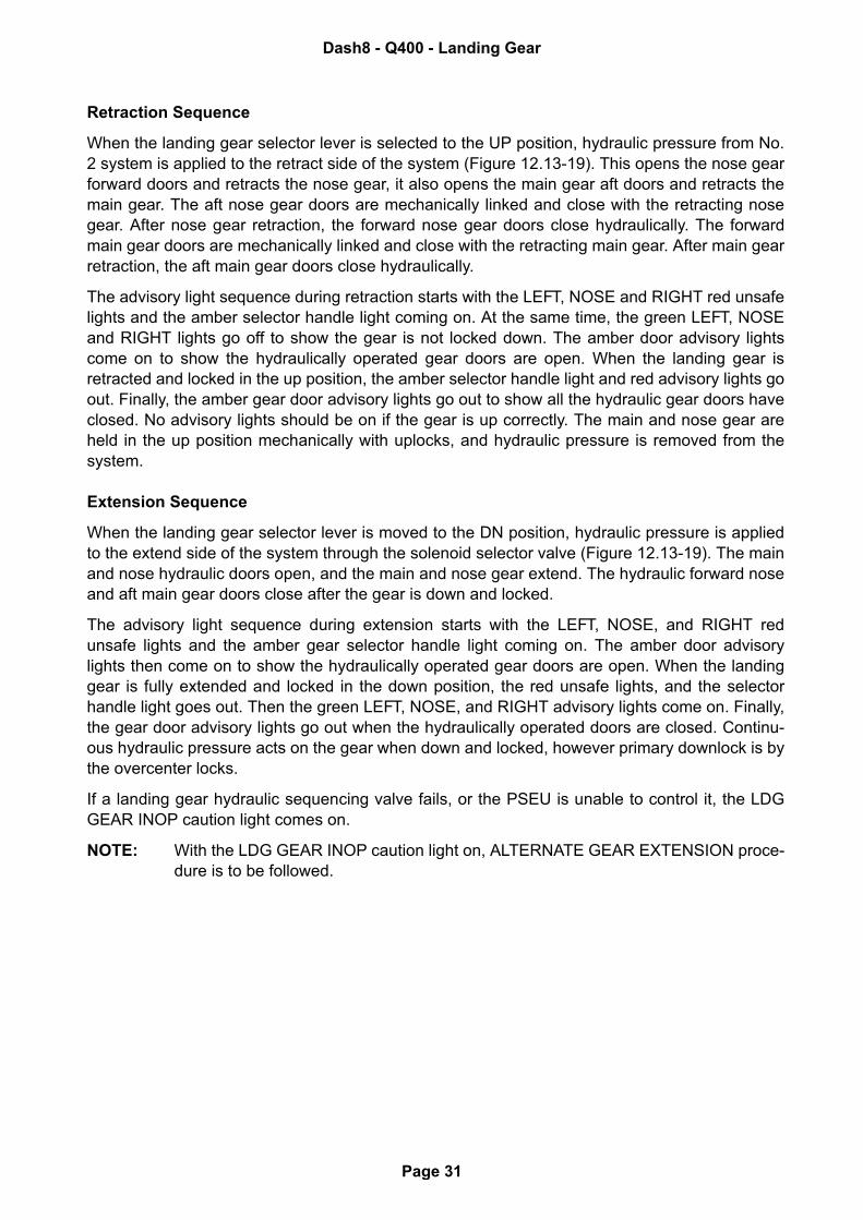
Figure 12.13-20 Alternate Landing Gear Extension Schematic
LA
ND
ING
GE
AR
AL
TE
RN
AT
E R
EL
EA
SE
DO
OR
(O
PE
N)
MA
IN D
OO
RU
PLO
CK
RE
LE
AS
E
LA
ND
ING
GE
AR
AL
TE
RN
AT
E E
XT
EN
SIO
ND
OO
R (
OP
EN
)
HA
ND
PU
MP
NO
SE
GE
AR
UP
LO
CK
RE
LE
AS
E
NO
SE
DO
OR
UP
LO
CK
RE
LE
AS
E
HY
DR
AU
LIC
PR
ES
SU
RE
CA
BLE
CIR
CU
IT/
LE
GE
ND
TO
MA
IN G
EA
RA
UX
ILIA
RY
AC
TU
AT
OR
S
MA
IN G
EA
RU
PLO
CK
RE
LE
AS
E
CO
NT
RO
L L
INK
AG
E
MA
IN L
/G R
EL
EA
SE
PU
LL F
ULLY
DO
WN
BA
A
B
EN
SU
RE
ALL W
HE
EL W
ELLS
AR
E C
LE
AR
OF
OB
ST
RU
CT
ION
SB
EF
OR
E C
LO
SIN
G A
CC
ES
S P
AN
EL
TO
CLO
SE
DU
MP
VA
LV
E.
CA
UT
ION
Dash8 - Q400 - Landing Gear
Page 32
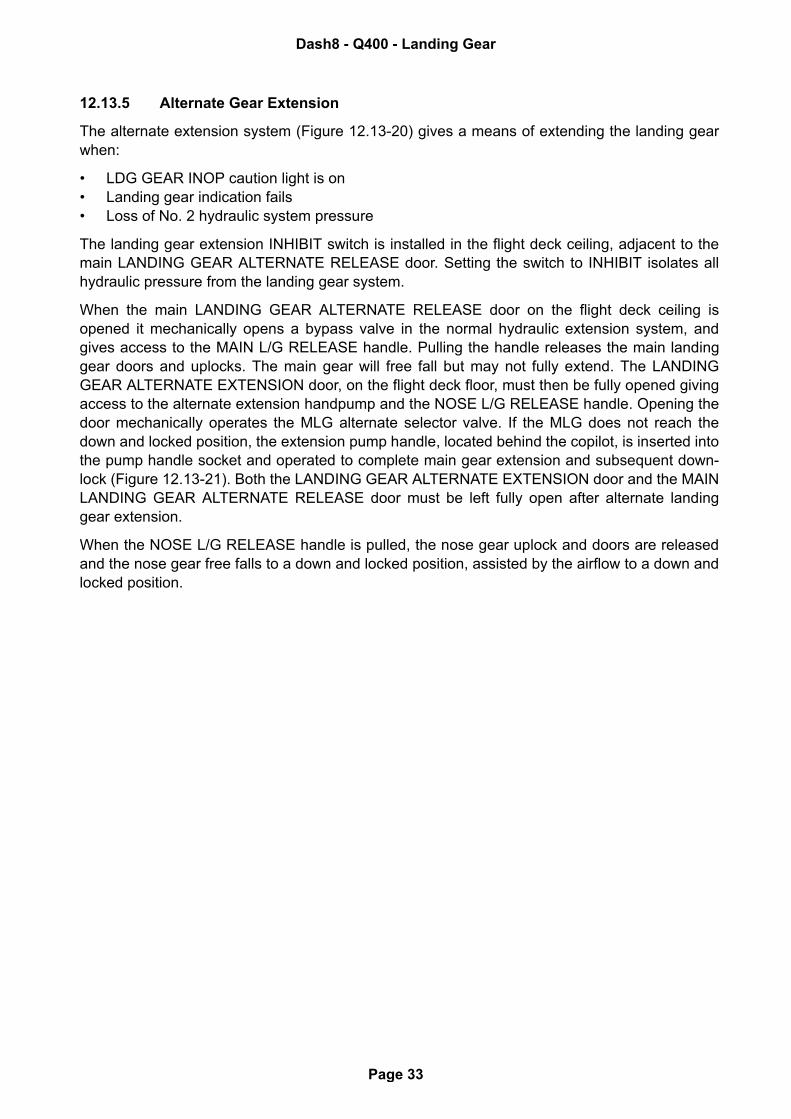
12.13.5 Alternate Gear Extension
The alternate extension system (Figure 12.13-20) gives a means of extending the landing gearwhen:
• LDG GEAR INOP caution light is on• Landing gear indication fails• Loss of No. 2 hydraulic system pressure
The landing gear extension INHIBIT switch is installed in the flight deck ceiling, adjacent to themain LANDING GEAR ALTERNATE RELEASE door. Setting the switch to INHIBIT isolates allhydraulic pressure from the landing gear system.
When the main LANDING GEAR ALTERNATE RELEASE door on the flight deck ceiling isopened it mechanically opens a bypass valve in the normal hydraulic extension system, andgives access to the MAIN L/G RELEASE handle. Pulling the handle releases the main landinggear doors and uplocks. The main gear will free fall but may not fully extend. The LANDINGGEAR ALTERNATE EXTENSION door, on the flight deck floor, must then be fully opened givingaccess to the alternate extension handpump and the NOSE L/G RELEASE handle. Opening thedoor mechanically operates the MLG alternate selector valve. If the MLG does not reach thedown and locked position, the extension pump handle, located behind the copilot, is inserted intothe pump handle socket and operated to complete main gear extension and subsequent down-lock (Figure 12.13-21). Both the LANDING GEAR ALTERNATE EXTENSION door and the MAINLANDING GEAR ALTERNATE RELEASE door must be left fully open after alternate landinggear extension.
When the NOSE L/G RELEASE handle is pulled, the nose gear uplock and doors are releasedand the nose gear free falls to a down and locked position, assisted by the airflow to a down andlocked position.
Dash8 - Q400 - Landing Gear
Page 33
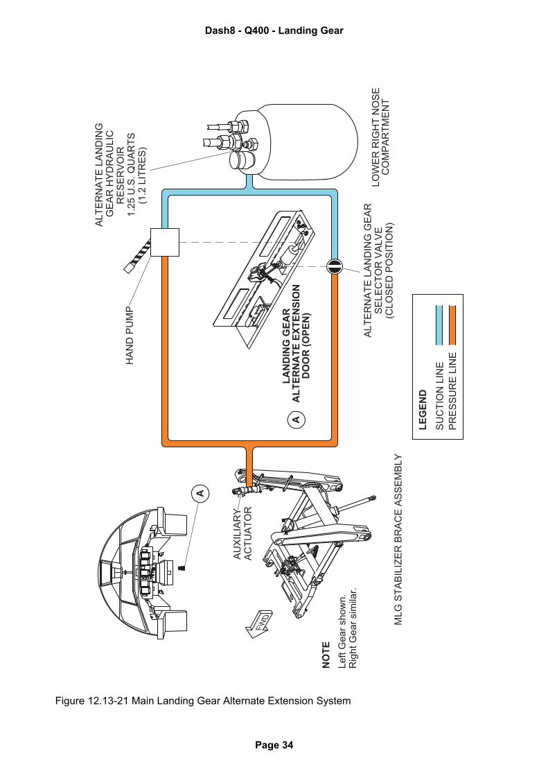
Figure 12.13-21 Main Landing Gear Alternate Extension System
SU
CT
ION
LIN
E
LE
GE
ND
A
MLG
ST
AB
ILIZ
ER
BR
AC
E A
SS
EM
BLY
LO
WE
R R
IGH
T N
OS
EC
OM
PA
RT
ME
NT
LA
ND
ING
GE
AR
AL
TE
RN
AT
E E
XT
EN
SIO
ND
OO
R (
OP
EN
)A
AU
XIL
IAR
YA
CT
UA
TO
RFW
D
ALT
ER
NA
TE
LA
ND
ING
GE
AR
SE
LE
CT
OR
VA
LV
E(C
LO
SE
D P
OS
ITIO
N)
PR
ES
SU
RE
LIN
E
ALT
ER
NA
TE
LA
ND
ING
GE
AR
HY
DR
AU
LIC
RE
SE
RV
OIR
1.2
5 U
.S. Q
UA
RT
S(1
.2 L
ITR
ES
)H
AN
D P
UM
P
NO
TE
Left G
ear
show
n.
Rig
ht G
ear
sim
ilar.
Dash8 - Q400 - Landing Gear
Page 34
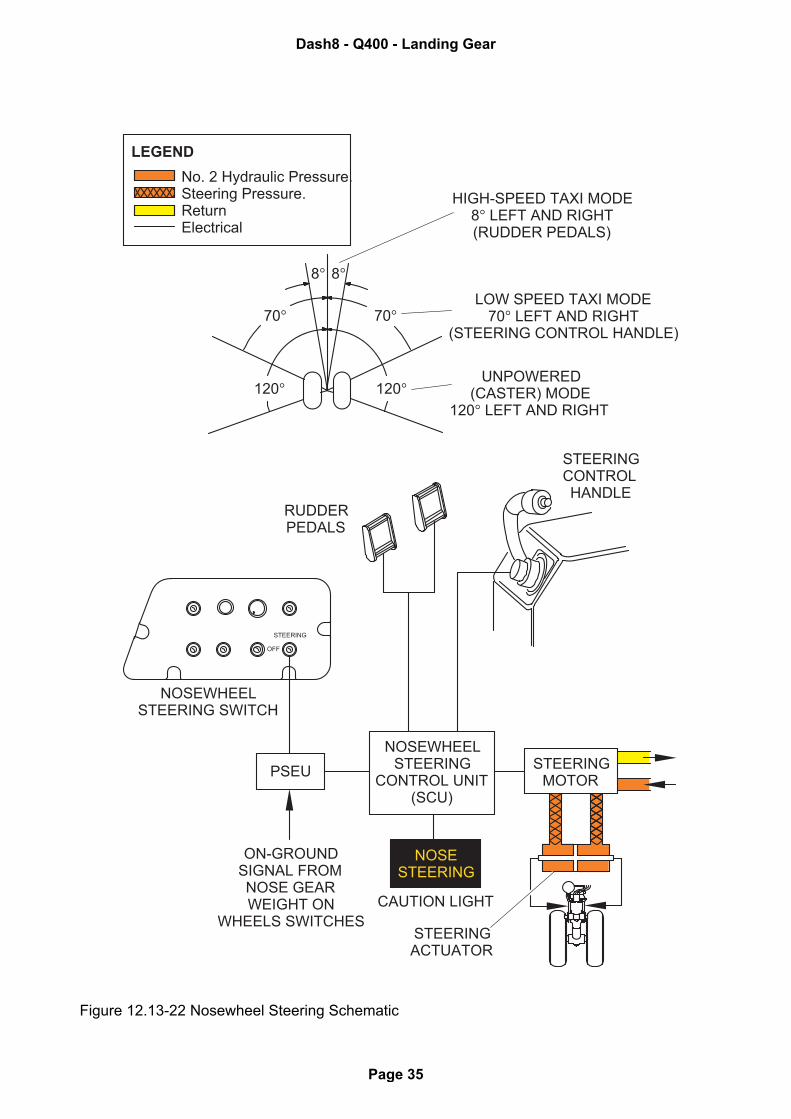
Figure 12.13-22 Nosewheel Steering Schematic
NOSESTEERING
fs number
LOW SPEED TAXI MODE70° LEFT AND RIGHT
(STEERING CONTROL HANDLE)
HIGH-SPEED TAXI MODE8° LEFT AND RIGHT(RUDDER PEDALS)
UNPOWERED(CASTER) MODE
120° LEFT AND RIGHT
8° 8°
70°70°
120° 120°
OFF
STEERING
PSEU
NOSEWHEELSTEERING
CONTROL UNIT(SCU)
STEERINGMOTOR
ON-GROUNDSIGNAL FROMNOSE GEARWEIGHT ON
WHEELS SWITCHESCAUTION LIGHT
STEERINGACTUATOR
NOSEWHEELSTEERING SWITCH
RUDDERPEDALS
STEERINGCONTROLHANDLE
LEGEND
No. 2 Hydraulic Pressure.Steering Pressure.ReturnElectrical
Dash8 - Q400 - Landing Gear
Page 35
12.13.6 Nosewheel Steering System
Directional control on the ground is by the nosewheel steering (NWS) system (Figure 12.13-22),powered by the No. 2 hydraulic system. Steering control is by either the Steering Hand Control orthe rudder pedals. The Steering Hand Control turns the nosewheel up to 70° either side of centerfor low speed taxi. Steering with the rudder pedals turns the nosewheel up to 8° either side ofcenter for high-speed taxi, take-off and landing roll. After take-off, the nosewheel automaticallycenters before retraction.
The hand control, located on the Pilot’s Side console, is self-centering and operates when theSTEERING switch is set to the STEERING position. The nosewheel must be within 70° of centerfor the steering to work. An index mark on the hand control shows the relative position of thenosewheel against a fixed STEERING RANGE decal. With the STEERING switch set to STEER-ING, power is directed to the nosewheel Steering Control Unit (SCU), if the nose gear is downand locked with weight-on-wheels.
The nosewheel will revert to a passive shimmy dampened castoring mode if:
• The nosewheel angle is greater than 70°• The SCU detects a failure• STEERING switch is set to OFF
In the passive mode, the nosewheel will castor up to 120° either side of center. Differential brak-ing and/or power may be used for directional control in the passive mode.
The NOSE STEERING caution light comes on if:
• SCU detects a failure with STEERING switch set to STEERING• hydraulic pressure detected in steering system with STEERING switch set to OFF
The NOSE STEERING caution light does not come on if electrical power is removed from theSCU.
When taxiing in reverse the STEERING switch must be selected on. However, no steering is per-mitted with either the tiller or the rudder pedals.
NOTE: Nosewheel steering using the hand control is limited to forward taxiing only, with theSTEERING switch set to the STEERING position.
CAUTION: Do not set the STEERING switch to STEERING if tow bar is connected to nose gear.
Dash8 - Q400 - Landing Gear
Page 36
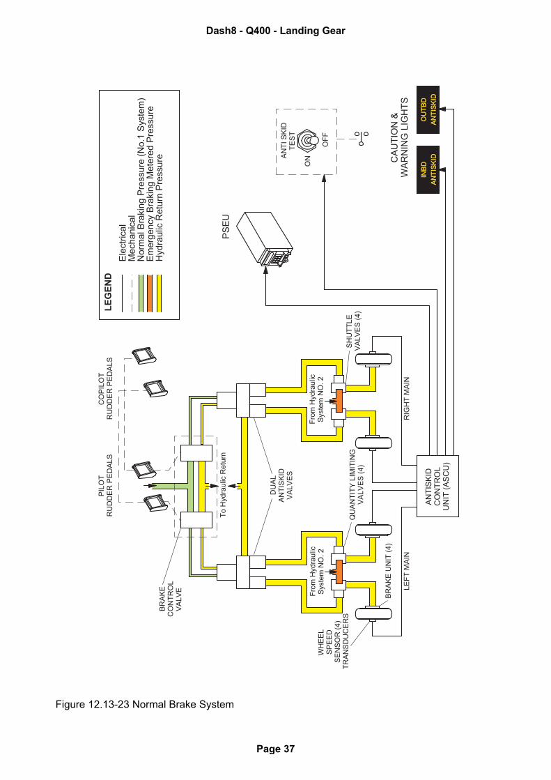
Figure 12.13-23 Normal Brake System
OU
TB
D
AN
TIS
KID
INB
D
AN
TIS
KID
LE
GE
ND
Ele
ctrica
lM
ech
anic
al
Norm
al B
raki
ng P
ress
ure
(N
o.1
Sys
tem
)E
merg
ency
Bra
king M
ete
red P
ress
ure
Hyd
raulic
Retu
rn P
ress
ure
QU
AN
TIT
Y L
IMIT
ING
VA
LV
ES
(4
)
CO
PIL
OT
RU
DD
ER
PE
DA
LS
Fro
m H
ydra
ulic
Sys
tem
NO
. 2
WH
EE
LS
PE
ED
SE
NS
OR
(4
)T
RA
NS
DU
CE
RS
SH
UT
TL
EV
AL
VE
S (
4)
RIG
HT
MA
IN
BR
AK
EC
ON
TR
OL
VA
LV
E
PS
EU
CA
UT
ION
&W
AR
NIN
G L
IGH
TS
AN
TI
SK
IDT
ES
T
ON
OF
F
To
Hyd
rau
lic R
etu
rn
Fro
m H
ydra
ulic
Sys
tem
NO
. 2
PIL
OT
RU
DD
ER
PE
DA
LS
DU
AL
AN
TIS
KID
VA
LV
ES
BR
AK
E U
NIT
(4
)
LE
FT
MA
IN
AN
TIS
KID
CO
NT
RO
LU
NIT
(A
SC
U)
OU
TB
D
AN
TIS
KID
INB
D
AN
TIS
KID
Dash8 - Q400 - Landing Gear
Page 37
12.13.7 Brake System
12.13.7.1 Normal Braking
Each main wheel is equipped with a multiple disc brake unit powered by the No. 1 hydraulic sys-tem (Figure 12.13-23). An Anti Skid Control Unit (ASCU) modulates the application of brakepressure to each brake unit.
Brake pressure is applied by pushing the pilot’s or copilot’s brake pedals (Figure 12.13-25).
The anti skid control unit:
• Monitors wheel speed• Modulates the brake pressure applied to each brake unit to prevent wheel lock-up• Gives maximum braking at all levels of runway friction.
The ANTI SKID switch on the copilot's glareshield panel operates the anti skid system when setto the ON position and the wheel speed is more than 10 knots. A start up self test of the anti skidcontrol circuits is made when the switch is moved to the ON, or momentary TEST. The start upself test is prevented with wheel speed more than 17 knots. If the ANTI SKID switch is held atTEST, the aeroplane on the ground, the INBD ANTISKID and the OUTBD ANTISKID cautionlights come on for six seconds and then go out. If the ANTI SKID switch is held at TEST in the air,with the landing gear extended and locked, will turn on the related caution lights for three sec-onds. If the ASCU senses a fault in the system, it turns on the related caution light.
The PSEU supplies weight-on-wheels and gear up and locked signals to the ASCU, to makesure that the brakes are off until the aeroplane has touched down and the wheels are spinning. Inconditions of low runway friction, the main gear wheels may not spin up before the aeroplane'sweight is fully on the wheels. In this case, the ASCU gives a 5 second delay before brake pres-sure is applied. This delay is immediately cancelled when wheel speed is more than 35 knots.
NOTE: Brake cooling times must be observed between a landing, or a low energy rejectedtake-off and a subsequent take-off, to make sure that sufficient brake energy is avail-able to bring the aeroplane to a complete stop if the subsequent take-off is rejected.
Dash8 - Q400 - Landing Gear
Page 38
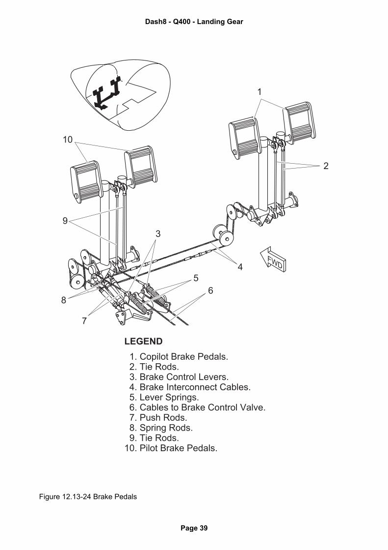
Figure 12.13-24 Brake Pedals
1
2
3
45
6
7
8
9
10
FWD
LEGEND
1. Copilot Brake Pedals. 2. Tie Rods. 3. Brake Control Levers. 4. Brake Interconnect Cables. 5. Lever Springs. 6. Cables to Brake Control Valve. 7. Push Rods. 8. Spring Rods. 9. Tie Rods.10. Pilot Brake Pedals.
Dash8 - Q400 - Landing Gear
Page 39
12.13.8 Emergency Brake System
The emergency/parking brake system (Figure 12.13-25) lets the brakes be applied if the normalbrake system fails, or for setting the parking brake. An EMERG BRAKE lever on the Engine Con-trol quadrant operates the system. The emergency/parking brake system is powered by No. 2hydraulic system, or by parking brake accumulator pressure. Hydraulic pressure to the emer-gency/parking brake system is shown on the PK BRK indicator on the PERMANENT SYSTEMSAREA (PSA) of the MFD.
The EMERG BRAKE lever operates against a spring to produce a resistance proportional to thebrake pressure applied as the lever is pulled back. There is no differential braking and no antiskid protection when using the EMERG BRAKE lever. If the emergency/parking brake system isused with No. 2 hydraulic system inoperative, the accumulator supplies brake pressure. A fullycharged accumulator is sufficient for approximately six applications.
The parking brake is engaged by pulling the EMERG BRAKE lever all the way back to the detentPARK position. This turns on the PARKING BRAKE caution light on the Caution and Warningpanel. The button on the side of the handle must be pushed to release the lever from the PARKdetent.
NOTE: Care should be taken when releasing the lever as considerable spring tension willforce the lever forward.
NOTE: With the parking brake set, application of engine power will cause the take-off warn-ing horn to sound.
A hand pump located in the right main wheel well can be used to increase the park brake systempressure. Minimum pressure required before engine start is 500 psi.
Alternatively, if an AC power supply is available, park brake system pressure can be increasedby running the SPU and the PTU.
Dash8 - Q400 - Landing Gear
Page 40
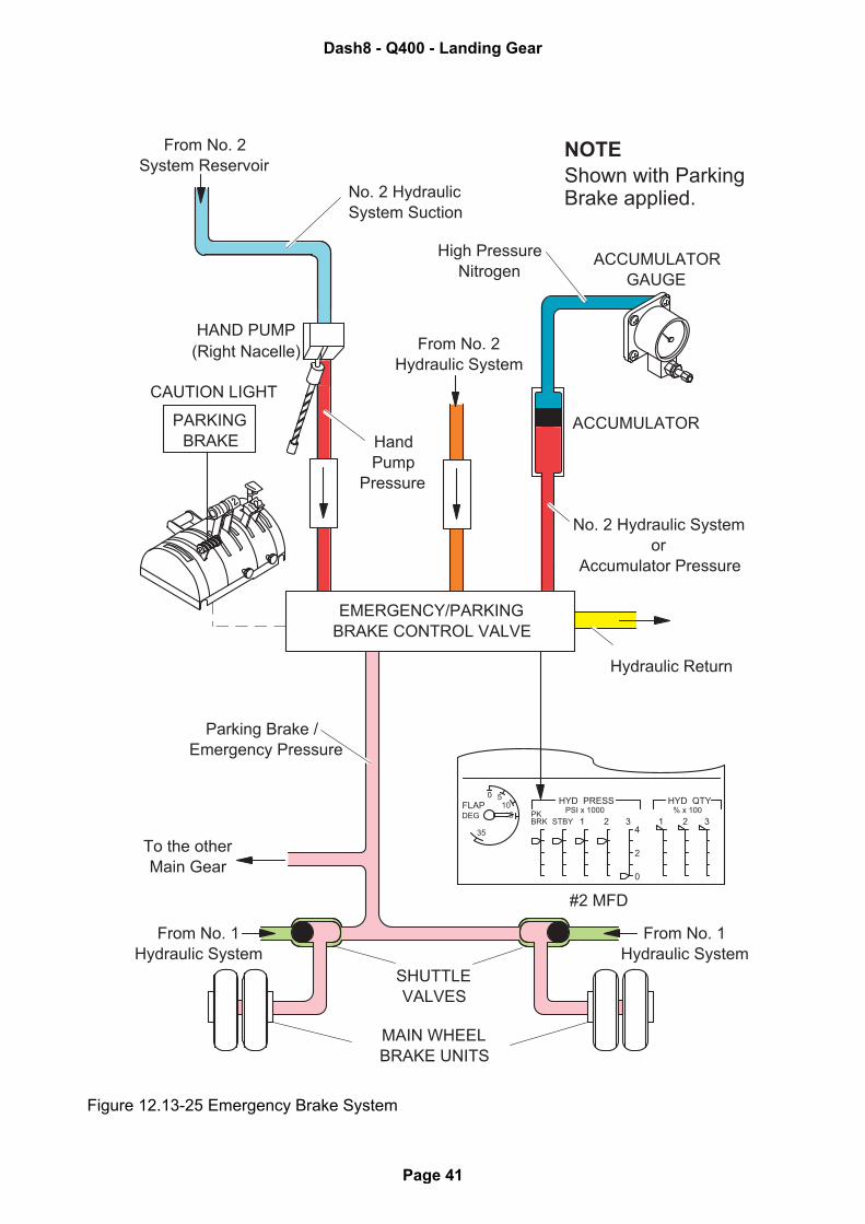
Figure 12.13-25 Emergency Brake System
FLAPDEG
35
1050
HYD PRESS HYD QTY
PKSTBY
PSI x 1000 % x 100
BRK 1 2 3 1 2 34
2
0
High PressureNitrogen
Parking Brake / Emergency Pressure
No. 2 HydraulicSystem Suction
PARKINGBRAKE
#2 MFD
From No. 2System Reservoir
From No. 2Hydraulic System
ACCUMULATORGAUGE
HAND PUMP
CAUTION LIGHT
MAIN WHEELBRAKE UNITS
From No. 1Hydraulic System
SHUTTLEVALVES
To the otherMain Gear
NOTEShown with ParkingBrake applied.
EMERGENCY/PARKINGBRAKE CONTROL VALVE
ACCUMULATOR
(Right Nacelle)
No. 2 Hydraulic Systemor
Accumulator Pressure
HandPump
Pressure
From No. 1Hydraulic System
Hydraulic Return
Dash8 - Q400 - Landing Gear
Page 41
12.13.9 Tires
12.13.9.1 Tire Fill Valve Gauges
Tire pressure gauges are offered as a customer option, to operators who want a visual means ofchecking tire pressures during a walk-around. The dial gauge is integral with the inflation valveand mounted in the same location on the wheel without any additional installation requirements.
A gauge is mounted on each MLG and NLG wheel and has a dial face with a shaded portion ofits face denoting the proper inflation pressure plus a 5% tolerance.
The gauge itself uses a Bourdon tube with the closed end attached to a pointer and the other endvented to the tire interior through the inflation valve bore.
12.13.9.2 Tire Inspection (Removal criteria)
General
Dunlop tires fitted to Q400 has two layers of nylon fabric placed between the casing plies andthe base of the tread grooves. This Inter Tread Fabric (also called reinforcement fabrics) formspart of the wearable tread pattern and will be exposed during the life of the tread. (Ref Figure12.35.26.)
• Examine the tires for signs of wear, damage and other deterioration.
1) Wear
• Remove the tire when tread has worn to the base of any grove or if any casing plies areexposed.
Note: Tires found to be exhibiting the above removal wear standard, which at the time is atan out-station, the replacement can be postponed to first night stop or to the basewhichever comes first.
2) Cuts or cracking
a) Tread
• Remove tire if any cut or crack penetrate any casing plies.
• Remove tire if cracking undercuts ribs.
• Remove tire if any cut extend more than 35 mm or 50% of any tread rib and has a treaddepth of 50% or more than existing tread depth.
b) Sidewall
• Remove tire if cracking is found in the sidewall.
Note: If only the first casing ply is damaged, the replacement of the tire can be postponedto the first night stop or to base whichever comes first.
3) Bulges or Air Bubbles
• Remove tires if bulges or air bubbles are found in the tread or in the sidewall.
Note: Removal of tires exhibiting above removal standard may be postponed to the firstnight stop or to base whichever comes first.
Dash8 - Q400 - Landing Gear
Page 42
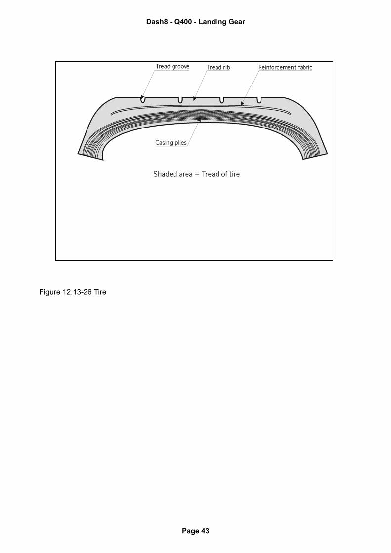
Figure 12.13-26 Tire
Dash8 - Q400 - Landing Gear
Page 43


![arXiv:1407.0927v1 [cs.SE] 3 Jul 2014Landing-Gear Extended Landing-Gear Retracted Landing-Gear Box Landing Wheel Door Figure 1: Landing Gear System such as airport runways [11]. Three](https://static.fdocuments.in/doc/165x107/5e9397289f16a23cdf089611/arxiv14070927v1-csse-3-jul-2014-landing-gear-extended-landing-gear-retracted.jpg)