120T (TM34T) Parts Manual - niftylift.com · Por favor, observe que en el momento de pasar a...
128
120T TM34T illustrated parts manual Manuel illustré de pièces détachées Illustrierte Stückliste Manual de piezas ilustrado M50120/13 Issue 13 (November 2012)
Transcript of 120T (TM34T) Parts Manual - niftylift.com · Por favor, observe que en el momento de pasar a...

120TTM34T
illustrated parts manual
Manuel illustré de pièces détachées
Illustrierte Stückliste
Manual de piezas ilustrado
M50120/13
Issue 13(November 2012)


120T (TM34T)
illustrated parts manualManuel illustré de pièces détachées Illustrierte Stückliste Manual de piezas ilustrado
Please Note, at the time of going to press, all information, illustrations details and descriptions contained herein are valid. Niftylift reserves the right to change, alter, modify or improve its products without any obligation to install them on previously manufactured machines.
Readers of this manual requiring further information should contact us at:
Niftylift Ltd. Niftylift Inc.Fingle Drive 1525 S.Buncombe RoadStonebridge GreerMilton Keynes SC 29651MK13 OER USAUnited Kingdom
Tel +44 (0)1908 857899 1 864 968 8881Fax +44 (0)1908 227460 1 864 968 8836
Ordering of PartsWhen ordering a replacement part for your Niftylift product, please state the following:
• Machine Model and Serial number Niftylift Part number
• Full description of the part Quantity required
• Purchase Order number Destination address
Machine Information
Model number. . . . . . . . . . . . . . . . . . . . . . . . . . . . . Date of Purchase. . . . . . . . . . . . . .
Serial number . . . . . . . . . . . . . . . . . . . . . . . . . . . . .
Veuillez noter qu'au moment de la mise sous presse, l'ensemble des informations, illustrations, détails et descriptions, contenus dans le présent document, sont valides. Niftylift se réserve le droit de changer ou d'améliorer ses produits sans obligation de montage sur les anciennes machines.
Pour toutes informations supplémentaires, veuillez nous contacter à:
Niftylift Ltd. Niftylift Inc.Fingle Drive 1525 S.Buncombe RoadStonebridge GreerMilton Keynes SC 29651MK13 OER USAUnited Kingdom
Tel +44 (0)1908 857899 1 864 968 8881Fax +44 (0)1908 227460 1 864 968 8836
Commande de piècesLors de la commande de pièces de rechange pour votre machine Niftylift, veuillez indiquer ce qui suit:
• Modèle et numéro de série de la machine Référence de la pièce Niftylift
• Description complète de la pièce Quantité requise
• Numéro de commande Adresse de destination
Informations relatives à la machine
Numéro de modèle . . . . . . . . . . . . . . . . . . . . . . . . . . . Date d'achat . . . . . . . . . . . . . . . . . . .
Numéro de série . . . . . . . . . . . . . . . . . . . . . . . . . . . . .

120T (TM34T)
iv issue 13
illustrated parts manual Manuel illustré de pièces détachées Illustrierte Stückliste Manual de piezas ilustrado
Bitte nehmen Sie zur Kenntnis, dass alle hierin enthaltenen Informationen, Illustrationen und Beschreibungen zum Zeitpunkt des Drucks gültig sind. Niftylift behält sich das Recht vor, Produkte zu wechseln, ändern, modifizieren und zu verbessern, ohne verpflichtet zu sein, sie an früher gefertigten Maschinen zu installieren.Wenn Leser dieser Anleitung weitere Informationen benötigen, wenden sie sich bitte an uns unter:
Niftylift Ltd. Niftylift Inc.Fingle Drive 1525 S.Buncombe RoadStonebridge GreerMilton Keynes SC 29651MK13 OER USAGroßbritannien
Tel +44 (0)1908 857899 1 864 968 8881Fax +44 (0)1908 227460 1 864 968 8836
Bestellen von ErsatzteilenBei der Bestellung eines Ersatzteils für Ihr Produkt von Niftylift geben Sie bitte folgende Einzelheiten an:
• Maschinenmodell und Seriennummer Niftylift Art.-Nr.
• Ausführliche Beschreibung des Teils Erforderliche Menge
• Bestellnummer Bestimmungsadresse
Maschineninformationen
Modellnummer . . . . . . . . . . . . . . . . . . . . . . . . . . . . . . Kaufdatum . . . . . . . . . . . . . . . . . . . .
Seriennummer . . . . . . . . . . . . . . . . . . . . . . . . . . . . . . .
Por favor, observe que en el momento de pasar a imprenta, toda la información, ilustraciones y descripciones contenidas en el presente documento eran válidas. Niftylift se reserva el derecho de cambiar, alterar, modificar o mejorar sus productos, sin obligación alguna de instalar dichos cambios en máquinas fabricadas anteriormente.Los usuarios de este manual que requieran más información, deberán ponerse en contacto con nosotros en:
Niftylift Ltd. Niftylift Inc.Fingle Drive 1525 S.Buncombe RoadStonebridge GreerMilton Keynes SC 29651MK13 OER USAUnited Kingdom
Tel +44 (0)1908 857899 1 864 968 8881Fax +44 (0)1908 227460 1 864 968 8836
Pedido de piezasAl realizar el pedido de una pieza de recambio para su producto Niftylift, sírvase especificar lo siguiente:
• Modelo y número de serie de la máquina Número de pieza Niftylift
• Descripción completa de la pieza Cantidad requerida
• Número de orden de compra Dirección de destino
Información de la máquina
Número de modelo . . . . . . . . . . . . . . . . . . . . . . . . . . . Fecha de compra . . . . . . . . . . . . . . .
Número de serie . . . . . . . . . . . . . . . . . . . . . . . . . . . . .

Parts Order Form (make copies for use)
Bon de commande de pièces (Faire des photocopies pour vos commandes ultérieures) tel +44 (0)1908 857899Bestellformular für Ersatzteile (bitte Kopien zur zukünftigen Verwendung machen) fax +44 (0)1908 227460Impreso de pedido de piezas (haga copias para el uso) www.niftylift.com
Note; If items have decals/labels attached, these are not included (unless stated otherwise), they must be ordered separately using the part (P) number printed on the decal.
Remarque : si les composants sont dotés d'autocollants/étiquettes, ceux-ci ne sont pas inclus (sauf avis contraire). Ils doivent être commandés séparément en indiquant le numéro de référence (P) imprimé sur l'autocollant.
Anmerkung: Wenn an Gegenständen Klebebilder/Etiketten angebracht sind, sind diese (sofern nicht anders angegeben) nicht en-thalten und müssen separat mit Hilfe der auf den Klebebildern abgedruckten Teilenummern (P) bestellt werden.
Nota: Si los artículos llevan acopladas calcomanías/etiquetas, éstas no se incluirán (a menos que se indique lo contrario); deberán pedirse por separado utilizando el número de pieza (P) impreso en la calcomanía.
Alternatively, details of your order can be emailed to [email protected], le détail de votre commande peut nous être envoyé par email à [email protected] Alternative können Sie Ihre Bestellung auch an [email protected] sendenAlternativamente, los detalles de su pedido pueden enviarse por e-mail a [email protected]
Part NumberRéférence pièce
Art.-Nr.Número de pieza
descriptiondescription
beschreibungdescripción
quantityquantitémenge
cantidad
priceprix
preisprecio
P
P
P
P
P
P
P
P
name nom name nombre
address adresse adresse dirección
telephone téléphone tel.-Nr. teléfono
fax fax-Nr.
email e-mail
date date datum fecha
delivery addressadresse de livraisonlieferadressedirección de entrega
purchase order numbernuméro de commandebestellnummernúmero de orden de compra
120T (TM34T)
vi
illustrated parts manual Manuel illustré de pièces détachées Illustrierte Stückliste Manual de piezas ilustrado
tab
le d
es m
atiè
res
inh
alts
verz
eich
nis
tab
la d
el c
ont
enid
oco
nten
ts
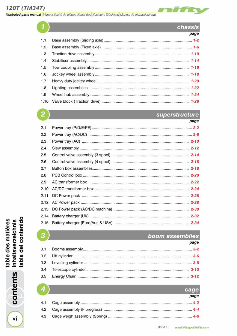
1 chassis page
1.1 Base assembly (Sliding axle)................................................................................. 1-2
1.2 Base assembly (Fixed axle) .................................................................................. 1-6
1.3 Traction drive assembly ...................................................................................... 1-10
1.4 Stabiliser assembly ............................................................................................. 1-14
1.5 Tow coupling assembly ...................................................................................... 1-16
1.6 Jockey wheel assembly ...................................................................................... 1-18
1.7 Heavy duty jockey wheel .................................................................................... 1-20
1.8 Lighting assemblies ............................................................................................ 1-22
1.9 Wheel hub assembly........................................................................................... 1-24
1.10 Valve block (Traction drive) ................................................................................ 1-26
2 superstructure page
2.1 Power tray (P/D/E/PE)............................................................................................ 2-2
2.2 Power tray (AC/DC) ............................................................................................... 2-6
2.3 Power tray (AC) .................................................................................................. 2-10
2.4 Slew assembly .................................................................................................... 2-12
2.5 Control valve assembly (3 spool) ....................................................................... 2-14
2.6 Control valve assembly (4 spool) ....................................................................... 2-16
2.7 Button box assemblies........................................................................................ 2-18
2.8 PCB Control box ................................................................................................. 2-20
2.9 AC transformer box ............................................................................................ 2-22
2.10 AC/DC transformer box ...................................................................................... 2-24
2.11 DC Power pack .................................................................................................. 2-26
2.12 AC Power pack ................................................................................................... 2-28
2.13 DC Power pack (AC/DC machine) ..................................................................... 2-30
2.14 Battery charger (UK) ........................................................................................... 2-32
2.15 Battery charger (Euro/Aus & USA) .................................................................... 2-34
3 boom assemblies page
3.1 Booms assembly.................................................................................................... 3-2
3.2 Lift cylinder ............................................................................................................. 3-6
3.3 Levelling cylinder ................................................................................................... 3-8
3.4 Telescope cylinder .............................................................................................. 3-10
3.5 Energy Chain ...................................................................................................... 3-12
4 cage page
4.1 Cage assembly ...................................................................................................... 4-2
4.2 Cage assembly (Fibreglass) ................................................................................. 4-4
4.3 Cage weigh assembly (Spring) ............................................................................. 4-6
issue 13
120T (TM34T)
ont
ents
illustrated parts manualManuel illustré de pièces détachées Illustrierte Stückliste Manual de piezas ilustrado
tab
le d
es m
atiè
res
inh
alts
verz
eich
nis
tab
la d
el c
ont
enid
o
4.4 Cage weigh assembly (Load Cell)......................................................................... 4-8
4.5 Control valve assembly (5 spool) ........................................................................ 4-10
4.6 Button box assemblies ........................................................................................ 4-12
5 labelling page
5.1 Label locations 120T.............................................................................................. 5-2
5.2 Label locations TM34T......................................................................................... 5-16
6 hydraulic hoses page
6.1 Hose kit 120T (TM34T)........................................................................................... 6-2
6.2 Traction Drive kit (P14205) .................................................................................... 6-6
Figures page
1.1 Base assembly (Sliding axle) ........................................................... 1-3
1.2 Base assembly (Fixed axle) ............................................................. 1-7
1.3 Traction drive assembly .................................................................. 1-11
1.4 Stabiliser assembly ......................................................................... 1-15
1.5 Tow coupling assembly .................................................................. 1-17
1.6 Jockey wheel assembly .................................................................. 1-19
1.7 Heavy duty jockey wheel ............................................................... 1-21
1.8 Lighting assemblies ........................................................................ 1-23
1.9 Wheel hub assembly....................................................................... 1-25
1.10 Valve block assembly (Traction drive) ............................................ 1-27
2.1 Power tray (P/D/E/PE) ....................................................................... 2-3
2.2 Power tray (AC/DC) .......................................................................... 2-7
2.3 Power tray (AC) .............................................................................. 2-11
2.4 Slew assembly ................................................................................ 2-13
2.5 Control valve assembly (3 spool).................................................... 2-15
2.6 Control valve assembly (4 spool).................................................... 2-17
2.7 Button box assembly....................................................................... 2-19
2.8 PCB Control box.............................................................................. 2-21
2.9 AC transformer box ........................................................................ 2-23
2.10 AC/DC transformer ......................................................................... 2-25
2.11 DC Power pack .............................................................................. 2-27
2.12 AC Power pack ............................................................................... 2-29
2.13 DC Power pack (AC/DC machine) ................................................. 2-31
2.14 Battery charger (UK) ....................................................................... 2-33
2.15 Battery charger (Euro/Aus & USA) ................................................. 2-35
c
issue 13
3.1 Booms assembly............................................................................... 3-3
3.2 Lift cylinder ........................................................................................ 3-7
120T (TM34T)
viii
illustrated parts manual Manuel illustré de pièces détachées Illustrierte Stückliste Manual de piezas ilustrado
tab
le d
es m
atiè
res
inh
alts
verz
eich
nis
cont
ents
3.3 Levelling cylinder............................................................................... 3-9
3.4 Telescope cylinder ......................................................................... 3-11
3.5 Energy Chain ................................................................................. 3-13
4.1 Cage assembly.................................................................................. 4-3
4.2 Cage assembly (Fibreglass) ............................................................ 4-5
4.3 Cage weigh assembly (Spring)......................................................... 4-7
4.4 Cage weigh assembly (Load cell)..................................................... 4-9
4.5 Control valve assembly (5 spool)................................................... 4-11
4.6 Button boxes .................................................................................. 4-13
5.1 Label locations 120T ......................................................................... 5-3
5.2 Label locations TM34T ................................................................... 5-17
5.2 Labels (1-32).................................................................................. 5-18
5.3 Labels (33-50)................................................................................. 5-19
6.1 Hose kit 120T (TM34T) ...................................................................... 6-3
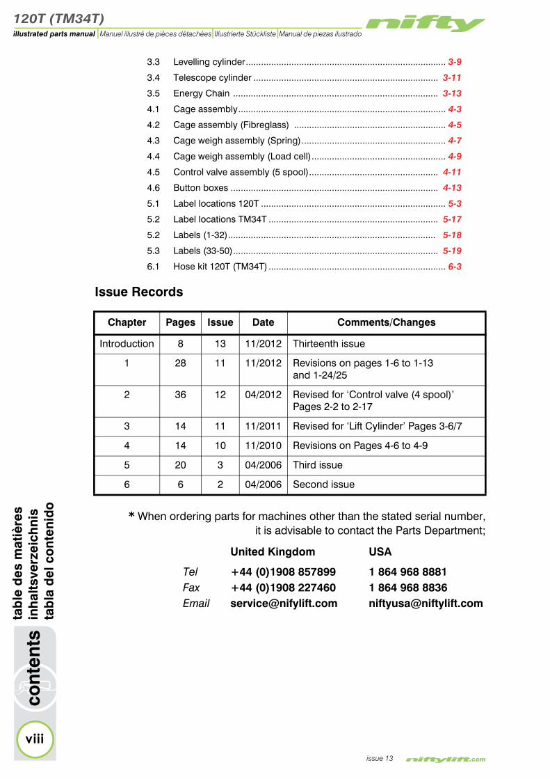
Issue Records
Chapter Pages Issue Date Comments/Changes
tab
la d
el c
ont
enid
o
issue 13
* When ordering parts for machines other than the stated serial number,it is advisable to contact the Parts Department;
United Kingdom USA
Tel +44 (0)1908 857899 1 864 968 8881Fax +44 (0)1908 227460 1 864 968 8836Email [email protected] [email protected]
Introduction 8 13 11/2012 Thirteenth issue
1 28 11 11/2012 Revisions on pages 1-6 to 1-13and 1-24/25
2 36 12 04/2012 Revised for ‘Control valve (4 spool)’ Pages 2-2 to 2-17
3 14 11 11/2011 Revised for ‘Lift Cylinder’ Pages 3-6/7
4 14 10 11/2010 Revisions on Pages 4-6 to 4-9
5 20 3 04/2006 Third issue
6 6 2 04/2006 Second issue

120T (TM34T)
1
illustrated parts manualManuel illustré de pièces détachéesIllustrierte StücklisteManual de piezas ilustrado
chassis assemblyfrench
germanspanish

120T (TM34T)
1–2
chas
sis
asse
mb
lyfr
ench
ger
man
span
ish
illustrated parts manual Manuel illustré de pièces détachées Illustrierte Stückliste Manual de piezas ilustrado
issue 11
1.1 Base assembly - Sliding axleItem Description Part Number
1 Slew ring P16817
2 Slew stop P20046
3Socket inlet - 240v
110v (a) Australia ONLY
P10174P10750P18303
4 Locating Pin P11377
5 Spring P10003
6 Spirit level P10228
7 Axle assy LH P15075
8 Mudguard P12818
9 Mudguard Bracket LH P24017
10 Rubber grommet P15087
11 Wheel & Tyre P12669
12 Bracket - Boom latch P20049
13 Boom latch P11392
14
Valve - Manual selectorLever ONLYRubber gaiter
P12578
P18090P19119
15 Micro switch P24994
16
Control valveSee “Control valve assembly (4 spool)” on page 2-16
P15518
17
Tow couplingTow coupling - USASee “Tow coupling assembly” on page 1-16
P10064P11513
18
Jockey wheelJockey wheel - USASee “Jockey wheel assembly” on page 1-18
P10065P25035
19 Brake rod (850 mm) P18918
20 Balance bar P25513

120T (TM34T)
fren
chg
erm
ansp
anis
hch
assi
s as
sem
bly
1–3
illustrated parts manualManuel illustré de pièces détachées Illustrierte Stückliste Manual de piezas ilustrado
issue 11
Figure 1.1 Base Assembly (Sliding axle)
2223
24
8 11
26
101
4 5
1027
30
25
29
28
2 3 3a
11
17
18
12 1314 15
19
2021
16
67
89
120T (TM34T)
1–4
chas
sis
asse
mb
lyfr
ench
ger
man
span
ish
illustrated parts manual Manuel illustré de pièces détachées Illustrierte Stückliste Manual de piezas ilustrado
issue 11
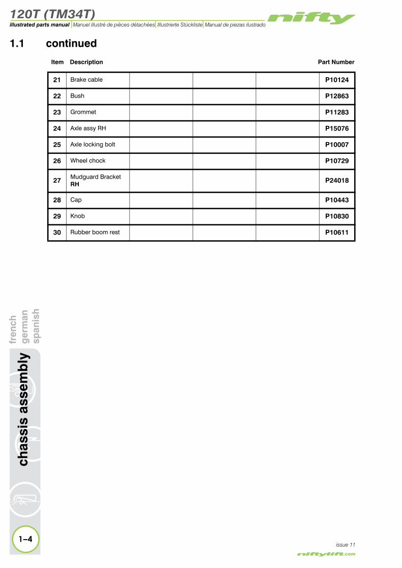
1.1 continued
Item Description Part Number
21 Brake cable P10124
22 Bush P12863
23 Grommet P11283
24 Axle assy RH P15076
25 Axle locking bolt P10007
26 Wheel chock P10729
27 Mudguard Bracket RH P24018
28 Cap P10443
29 Knob P10830
30 Rubber boom rest P10611

120T (TM34T)
fren
chg
erm
ansp
anis
hch
assi
s as
sem
bly
1–5
illustrated parts manualManuel illustré de pièces détachées Illustrierte Stückliste Manual de piezas ilustrado
issue 11
Figure 1.1 Base assembly (Sliding axle)
2223
24
8 11
26
101
4 5
1027
30
25
29
28
2 3 3a
11
17
18
12 1314 15
19
2021
16
67
89

120T (TM34T)
1–6
chas
sis
asse
mb
lyfr
ench
ger
man
span
ish
illustrated parts manual Manuel illustré de pièces détachées Illustrierte Stückliste Manual de piezas ilustrado
issue 11
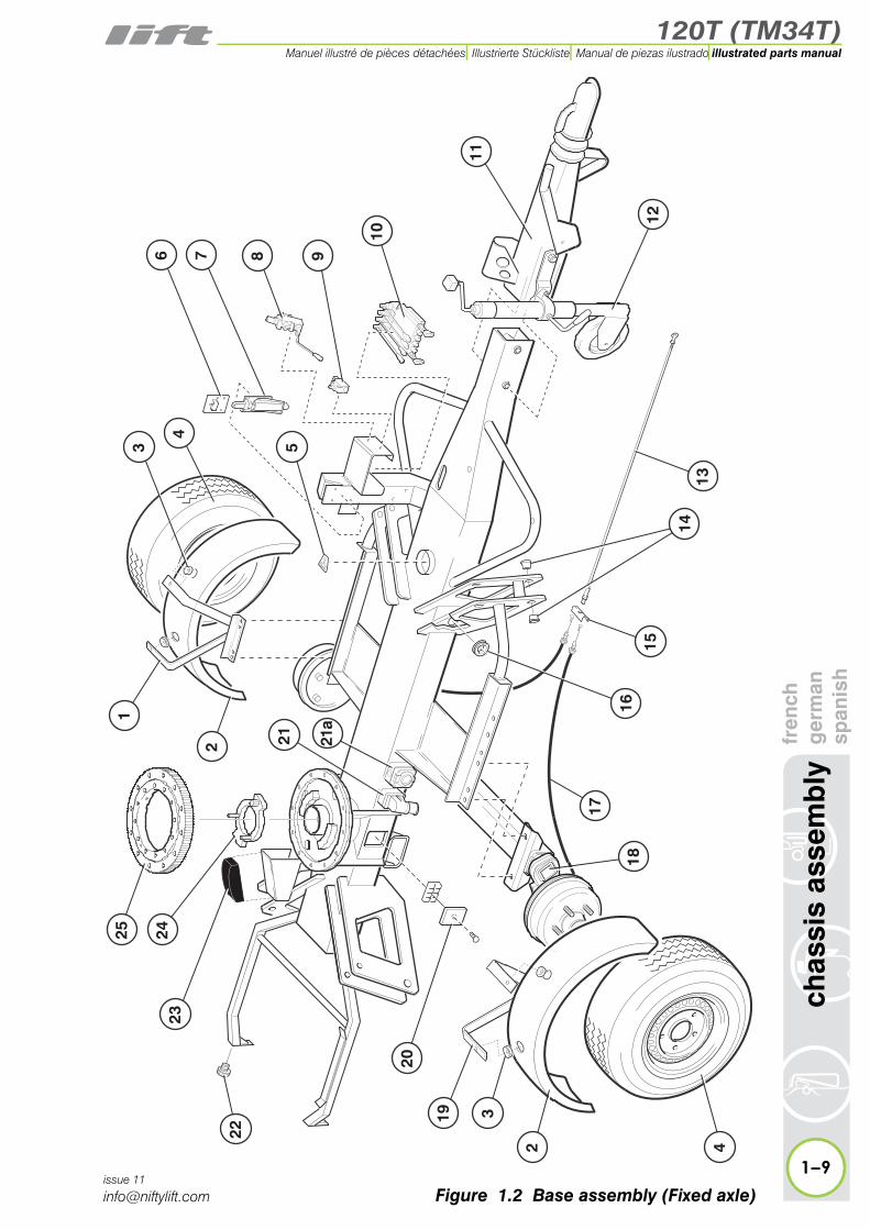
1.2 Base assembly - Fixed axleItem Description Part Number
1 Mudguard bracket LH P24017
2 Mudguard P12818
3 Rubber grommet P15087
4 Wheel and tyre P13086
5 Spirit level P10228
6 Bracket - Boom latch P20049
7 Boom latch P11392
8
Valve - Manual selectorLever ONLYRubber gaiter
P12578
P18090P19119
9 Micro switch P24994
10
Control valveSee “Control valve assembly (4 spool)” on page 2-16
P15518
11
Tow couplingTow coupling - USASee “Tow coupling assembly” on page 1-16
P10064P11513
12
Jockey wheelJockey wheel - USASee “Jockey wheel assembly” on page 1-18
P10065P25035
13 Brake rod (1700 mm) P16892
14 Bush P12863
15 Balance bar P25513
16 Grommet P11283
17 Brake cable P24706
18 Axle assembly P24705
19 Mudguard bracket RH P24018
20 Cap P10443

120T (TM34T)
fren
chg
erm
ansp
anis
hch
assi
s as
sem
bly
1–7
illustrated parts manualManuel illustré de pièces détachées Illustrierte Stückliste Manual de piezas ilustrado
issue 11
Figure 1.2 Base assembly (Fixed axle)
3
4
2
1
2425
13
15
42
319
17
18
14
16
23
22
20
21 21a
11
12
6 7
5
8 9
10

120T (TM34T)
1–8
chas
sis
asse
mb
lyfr
ench
ger
man
span
ish
illustrated parts manual Manuel illustré de pièces détachées Illustrierte Stückliste Manual de piezas ilustrado
issue 11
1.2 continued
Item Description Part Number
21Socket inlet - 240v
110v (a) Australia ONLY
P10174P10750P18303
22 Knob P10830
23 Rubber boom rest P10611
24 Slew stop P20046
25 Slew ring P16817
120T (TM34T)
fren
chg
erm
ansp
anis
hch
assi
s as
sem
bly
1–9
illustrated parts manualManuel illustré de pièces détachées Illustrierte Stückliste Manual de piezas ilustrado
issue 11
3
4
2
1
2425
13
15
42
319
17
18
14
16
23
22
20
21 21a
11
12
6 7
5
8 9
10
Figure 1.2 Base assembly (Fixed axle)
120T (TM34T)
1–10
chas
sis
asse
mb
lyfr
ench
ger
man
span
ish
illustrated parts manual Manuel illustré de pièces détachées Illustrierte Stückliste Manual de piezas ilustrado
issue 11
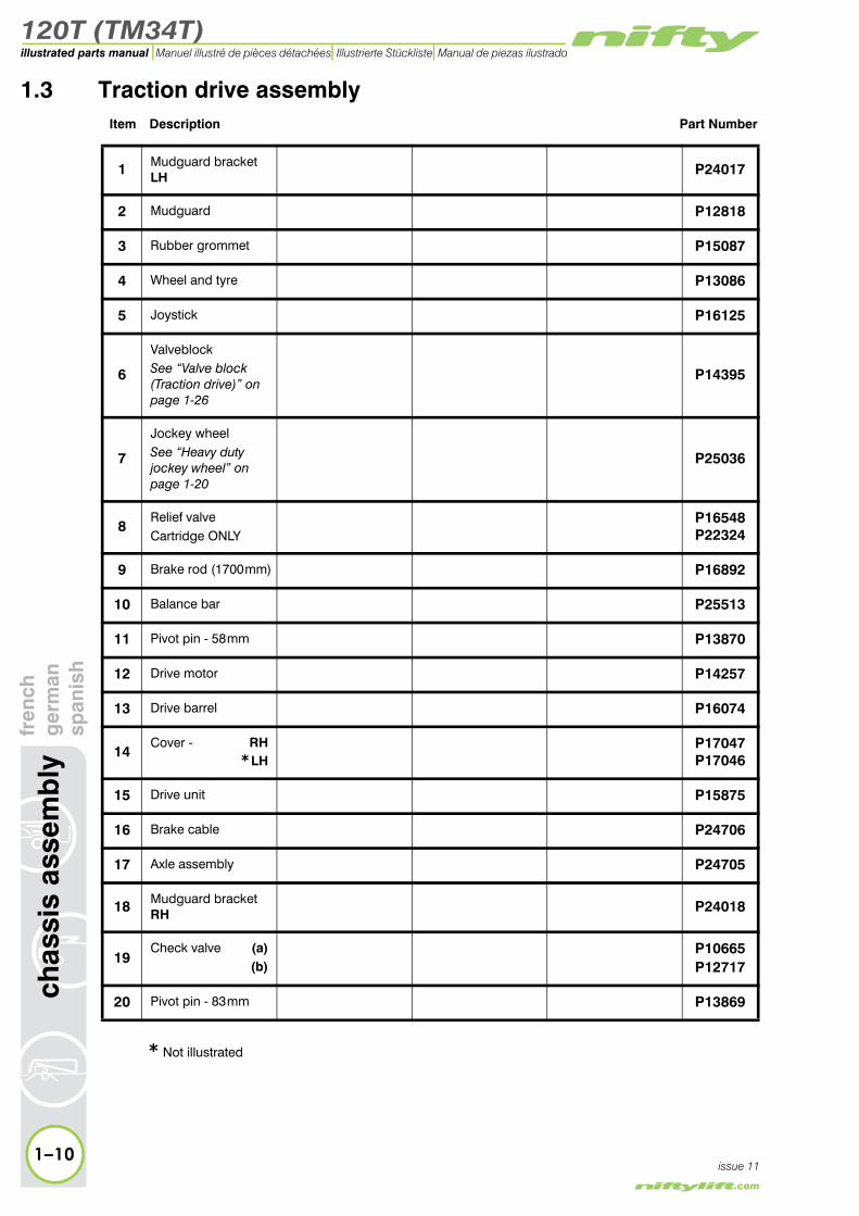
1.3 Traction drive assemblyItem Description Part Number
1 Mudguard bracket LH P24017
2 Mudguard P12818
3 Rubber grommet P15087
4 Wheel and tyre P13086
5 Joystick P16125
6
ValveblockSee “Valve block (Traction drive)” on page 1-26
P14395
7
Jockey wheelSee “Heavy duty jockey wheel” on page 1-20
P25036
8Relief valveCartridge ONLY
P16548P22324
9 Brake rod (1700 mm) P16892
10 Balance bar P25513
11 Pivot pin - 58 mm P13870
12 Drive motor P14257
13 Drive barrel P16074
14Cover - RH
* LHP17047P17046
15 Drive unit P15875
16 Brake cable P24706
17 Axle assembly P24705
18 Mudguard bracket RH P24018
19Check valve (a)
(b)P10665P12717
20 Pivot pin - 83 mm P13869
* Not illustrated

120T (TM34T)
fren
chg
erm
ansp
anis
hch
assi
s as
sem
bly
1–11
illustrated parts manualManuel illustré de pièces détachées Illustrierte Stückliste Manual de piezas ilustrado
issue 11
Figure 1.3 Traction drive assembly
5 6
2021
19b
22*
3
8
11
4
21
9
15
144
19a
2
318
16
12
13
1017
2426
23
25
15
7
120T (TM34T)
1–12
chas
sis
asse
mb
lyfr
ench
ger
man
span
ish
illustrated parts manual Manuel illustré de pièces détachées Illustrierte Stückliste Manual de piezas ilustrado
issue 11
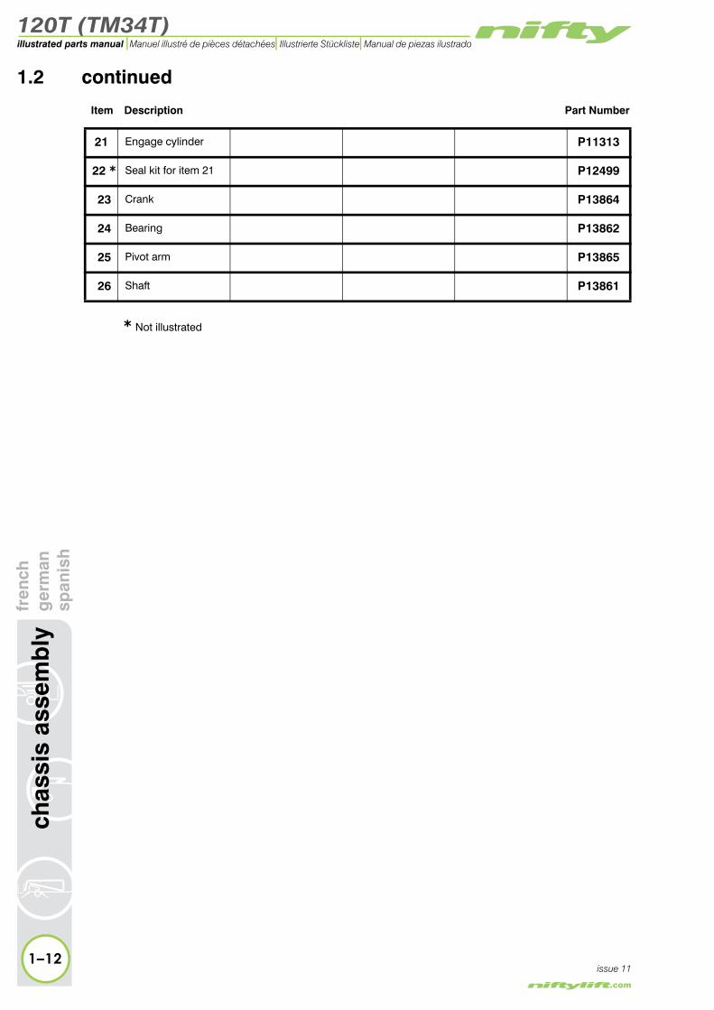
1.2 continued
Item Description Part Number
21 Engage cylinder P11313
22 * Seal kit for item 21 P12499
23 Crank P13864
24 Bearing P13862
25 Pivot arm P13865
26 Shaft P13861
* Not illustrated

120T (TM34T)
fren
chg
erm
ansp
anis
hch
assi
s as
sem
bly
1–13
illustrated parts manualManuel illustré de pièces détachées Illustrierte Stückliste Manual de piezas ilustrado
issue 11
Figure 1.3 Traction drive assembly
5 6
2021
19b
22*
3
8
11
4
21
9
15
144
19a
2
318
16
12
13
1017
2426
23
25
15
7
120T (TM34T)
1–14
chas
sis
asse
mb
lyfr
ench
ger
man
span
ish
illustrated parts manual Manuel illustré de pièces détachées Illustrierte Stückliste Manual de piezas ilustrado
issue 11
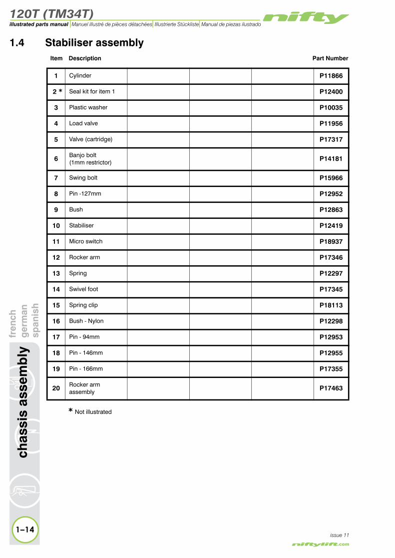
1.4 Stabiliser assemblyItem Description Part Number
1 Cylinder P11866
2 * Seal kit for item 1 P12400
3 Plastic washer P10035
4 Load valve P11956
5 Valve (cartridge) P17317
6 Banjo bolt(1mm restrictor) P14181
7 Swing bolt P15966
8 Pin -127mm P12952
9 Bush P12863
10 Stabiliser P12419
11 Micro switch P18937
12 Rocker arm P17346
13 Spring P12297
14 Swivel foot P17345
15 Spring clip P18113
16 Bush - Nylon P12298
17 Pin - 94mm P12953
18 Pin - 146mm P12955
19 Pin - 166mm P17355
20 Rocker armassembly P17463
* Not illustrated
120T (TM34T)
fren
chg
erm
ansp
anis
hch
assi
s as
sem
bly
1–15
illustrated parts manualManuel illustré de pièces détachées Illustrierte Stückliste Manual de piezas ilustrado
issue 11
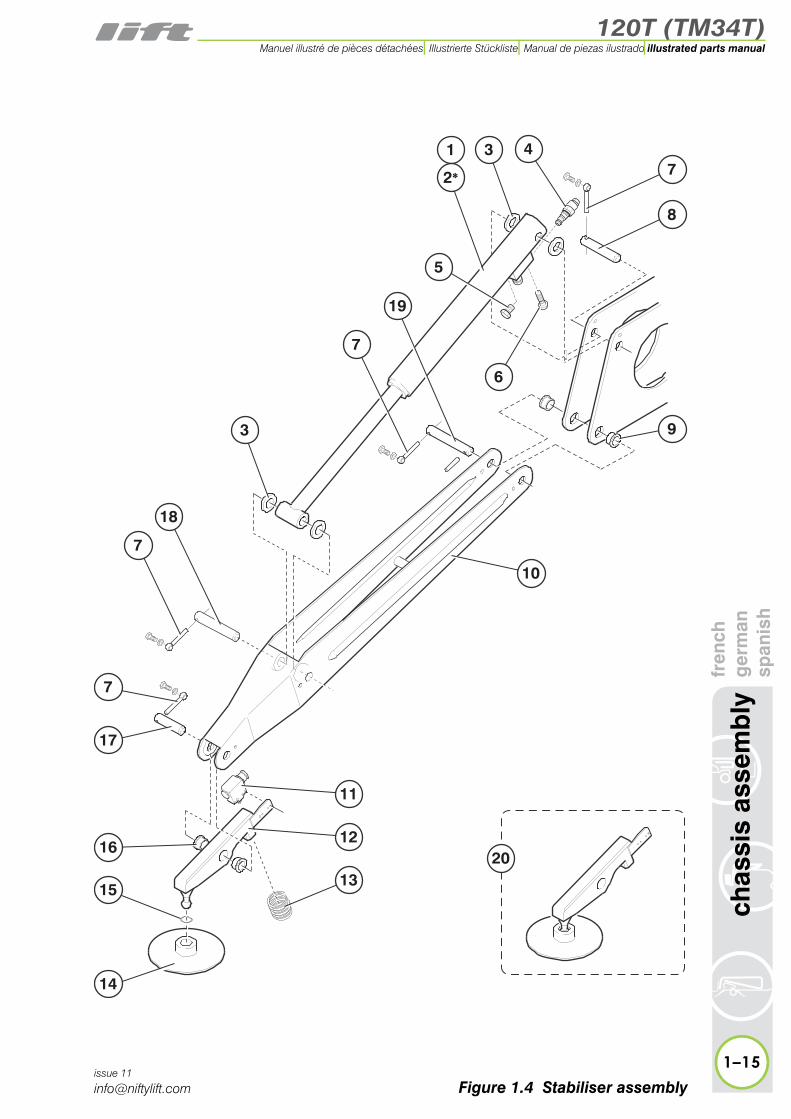
Figure 1.4 Stabiliser assembly
7
7
19
7
18
7
16
14
15
17
8
10
11
12
13
9
1
2*
43
3
5
6
20
120T (TM34T)
1–16
chas
sis
asse
mb
lyfr
ench
ger
man
span
ish
illustrated parts manual Manuel illustré de pièces détachées Illustrierte Stückliste Manual de piezas ilustrado
issue 11
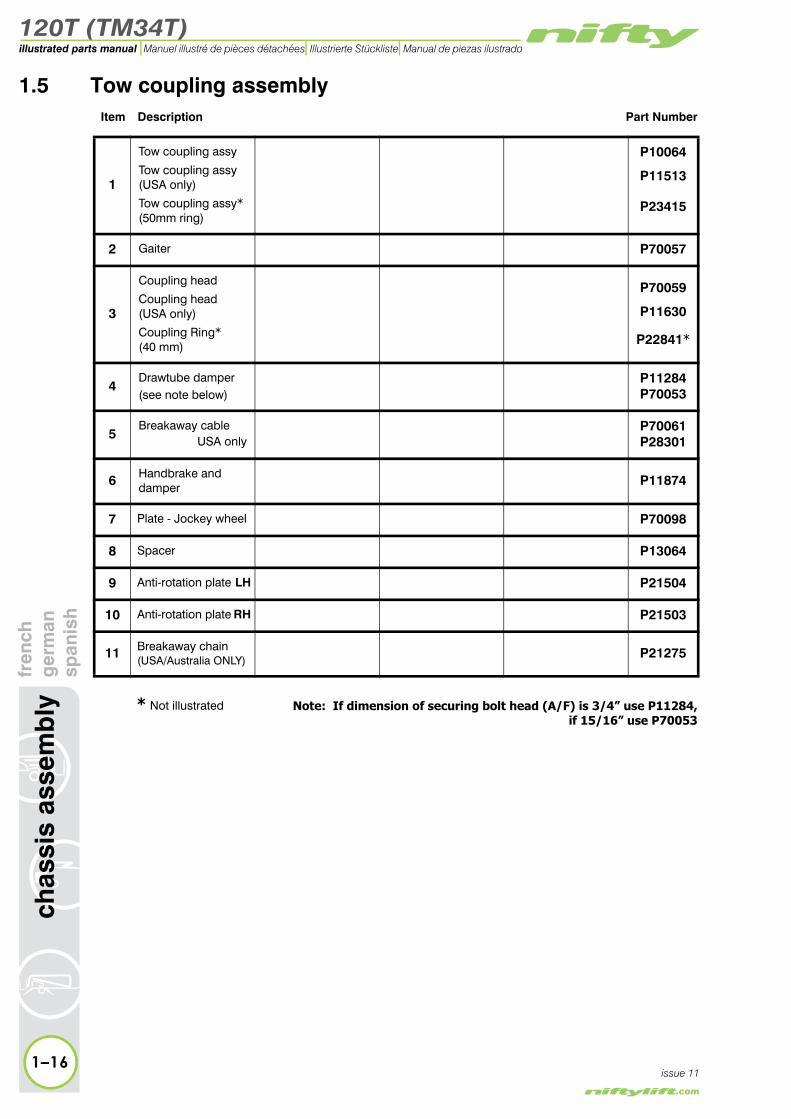
1.5 Tow coupling assemblyItem Description Part Number
1
Tow coupling assy
Tow coupling assy (USA only)
Tow coupling assy*(50mm ring)
P10064
P11513
P23415
2 Gaiter P70057
3
Coupling head
Coupling head (USA only)
Coupling Ring*(40 mm)
P70059
P11630
P22841*
4Drawtube damper(see note below)
P11284P70053
5Breakaway cable
USA onlyP70061P28301
6 Handbrake and damper P11874
7 Plate - Jockey wheel P70098
8 Spacer P13064
9 Anti-rotation plate LH P21504
10 Anti-rotation plate RH P21503
11 Breakaway chain(USA/Australia ONLY)
P21275
Note: If dimension of securing bolt head (A/F) is 3/4” use P11284, if 15/16” use P70053
* Not illustrated
120T (TM34T)
fren
chg
erm
ansp
anis
hch
assi
s as
sem
bly
1–17
illustrated parts manualManuel illustré de pièces détachées Illustrierte Stückliste Manual de piezas ilustrado
issue 11
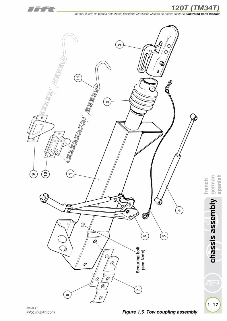
Figure 1.5 Tow coupling assembly
1
2
3
4
56
7
8
9 10
Sec
urin
g b
olt
(see
No
te)
11

120T (TM34T)
1–18
chas
sis
asse
mb
lyfr
ench
ger
man
span
ish
illustrated parts manual Manuel illustré de pièces détachées Illustrierte Stückliste Manual de piezas ilustrado
issue 11
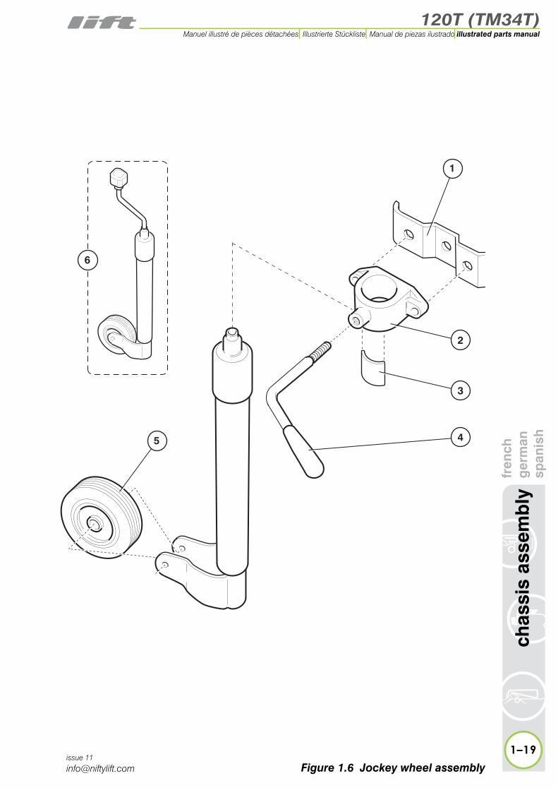
1.6 Jockey wheel assemblyItem Description Part Number
1 Plate P70098
2Clamp(Includes items 1, 3 and 4)
P10066
3 Pressure pad P11458
4 Clamp handle P70095
5 Solid wheel * P70093
6 Jockey wheel assemby P10065
* Note: Item 5 is only suitable for pre 2010 machines
120T (TM34T)
fren
chg
erm
ansp
anis
hch
assi
s as
sem
bly
1–19
illustrated parts manualManuel illustré de pièces détachées Illustrierte Stückliste Manual de piezas ilustrado
issue 11
Figure 1.6 Jockey wheel assembly
2
3
4
1
5
6

120T (TM34T)
1–20
chas
sis
asse
mb
lyfr
ench
ger
man
span
ish
illustrated parts manual Manuel illustré de pièces détachées Illustrierte Stückliste Manual de piezas ilustrado
issue 11
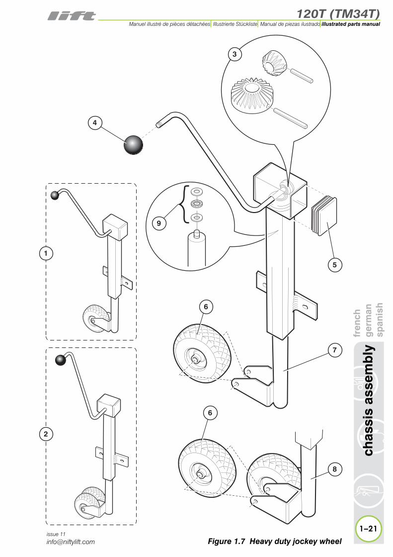
1.7 Heavy duty jockey wheelItem Description Part Number
1 *Jockey wheel A) assembly B)
P14065P25035
2 *Jockey wheel A) assembly B)(traction drive)
P13898P25036
3 *Gear kit A)
B)P15183P25037
4 Knob P70076
5 *Plastic Cap A)
B)P16480P25040
6 Wheel P16309
7 *Inner shaft A)
B)P14066P25038
8 *Inner shaft A)(Twin wheel) B)
P16308P25039
9 Bearing - Inner P11675
* A) Cap size (Item 5) is 90mm squareB) Cap size (Item 5) is 70mm square
120T (TM34T)
fren
chg
erm
ansp
anis
hch
assi
s as
sem
bly
1–21
illustrated parts manualManuel illustré de pièces détachées Illustrierte Stückliste Manual de piezas ilustrado
issue 11
Figure 1.7 Heavy duty jockey wheel
3
7
5
8
6
6
4
1
2
9
120T (TM34T)
1–22
chas
sis
asse
mb
lyfr
ench
ger
man
span
ish
illustrated parts manual Manuel illustré de pièces détachées Illustrierte Stückliste Manual de piezas ilustrado
issue 11
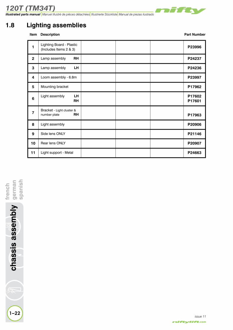
1.8 Lighting assembliesItem Description Part Number
1Lighting Board - Plastic(Includes Items 2 & 3)
P23996
2 Lamp assembly RH P24237
3 Lamp assembly LH P24236
4 Loom assembly - 6.8m P23997
5 Mounting bracket P17962
6Light assembly LH
RHP17602P17601
7Bracket - Light cluster & number plate RH P17963
8 Light assembly P20906
9 Side lens ONLY P21146
10 Rear lens ONLY P20907
11 Light support - Metal P24663

120T (TM34T)
fren
chg
erm
ansp
anis
hch
assi
s as
sem
bly
1–23
illustrated parts manualManuel illustré de pièces détachées Illustrierte Stückliste Manual de piezas ilustrado
issue 11
Figure 1.8 Lighting assemblies
1
610
113
4
2
57
6
5 8 9
US
A O
NLY
Aus
tral
ia O
NLY
120T (TM34T)
1–24
chas
sis
asse
mb
lyfr
ench
ger
man
span
ish
illustrated parts manual Manuel illustré de pièces détachées Illustrierte Stückliste Manual de piezas ilustrado
issue 11
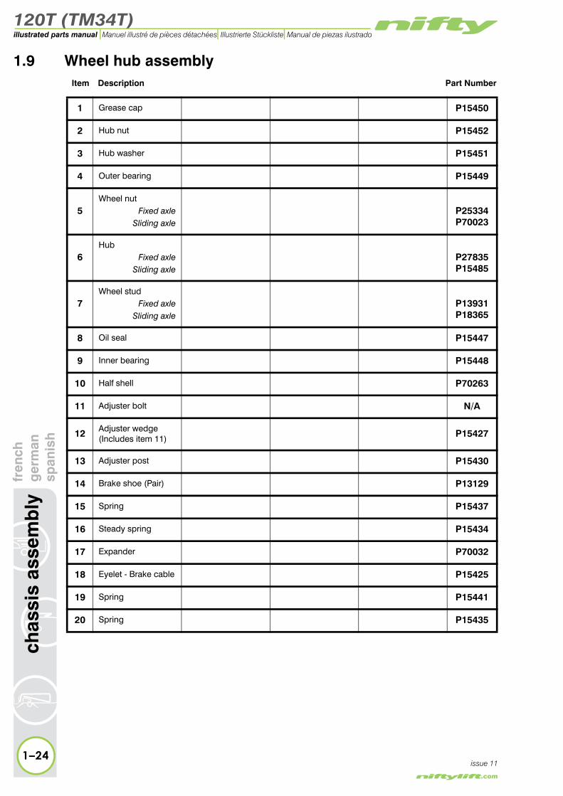
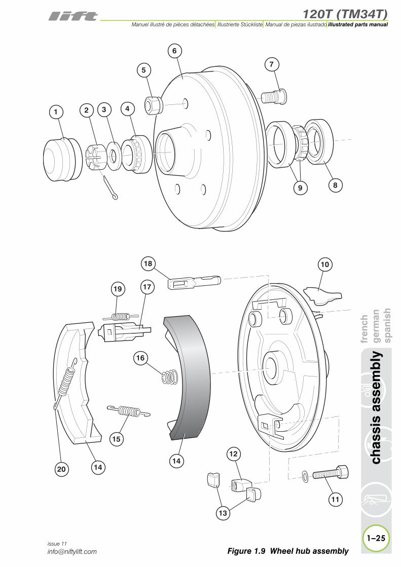
1.9 Wheel hub assemblyItem Description Part Number
1 Grease cap P15450
2 Hub nut P15452
3 Hub washer P15451
4 Outer bearing P15449
5Wheel nut
Fixed axleSliding axle
P25334P70023
6Hub
Fixed axleSliding axle
P27835P15485
7Wheel stud
Fixed axleSliding axle
P13931P18365
8 Oil seal P15447
9 Inner bearing P15448
10 Half shell P70263
11 Adjuster bolt N/A
12 Adjuster wedge(Includes item 11) P15427
13 Adjuster post P15430
14 Brake shoe (Pair) P13129
15 Spring P15437
16 Steady spring P15434
17 Expander P70032
18 Eyelet - Brake cable P15425
19 Spring P15441
20 Spring P15435
120T (TM34T)
fren
chg
erm
ansp
anis
hch
assi
s as
sem
bly
1–25
illustrated parts manualManuel illustré de pièces détachées Illustrierte Stückliste Manual de piezas ilustrado
issue 11
Figure 1.9 Wheel hub assembly
1
5
6
7
89
11
13
1214
14
15
10
16
18
19 17
20
2 3 4

120T (TM34T)
1–26
chas
sis
asse
mb
lyfr
ench
ger
man
span
ish
illustrated parts manual Manuel illustré de pièces détachées Illustrierte Stückliste Manual de piezas ilustrado
issue 11
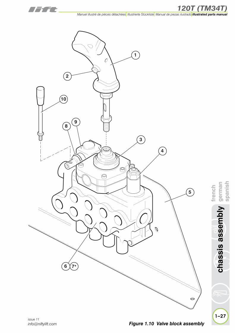
1.10 Valve block (Traction drive)Item Description Part Number
1 Joystick P16125
2 Button - Red P17994
3 Rubber gaiter P17921
4 Valve - Cartridge P19121
5 Bracket - Valveblock P13872
6 Valve block P14395
7 * Seal kit for item 6 P18156
8 Gaiter - Lever cap P19119
9 Lever cap P19120
10 Lever P16306
* Not illustrated
120T (TM34T)
fren
chg
erm
ansp
anis
hch
assi
s as
sem
bly
1–27
illustrated parts manualManuel illustré de pièces détachées Illustrierte Stückliste Manual de piezas ilustrado
issue 11
Figure 1.10 Valve block assembly
1
5
3
4
10
6
2
98
7*


120T (TM34T)
2
illustrated parts manualManuel illustré de pièces détachéesIllustrierte StücklisteManual de piezas ilustrado
superstructurefrench
germanspanish

120T (TM34T)illustrated parts manual Manuel illustré de pièces détachées Illustrierte Stückliste Manual de piezas ilustrado
sup
erst
ruct
ure
fren
chg
erm
ansp
anis
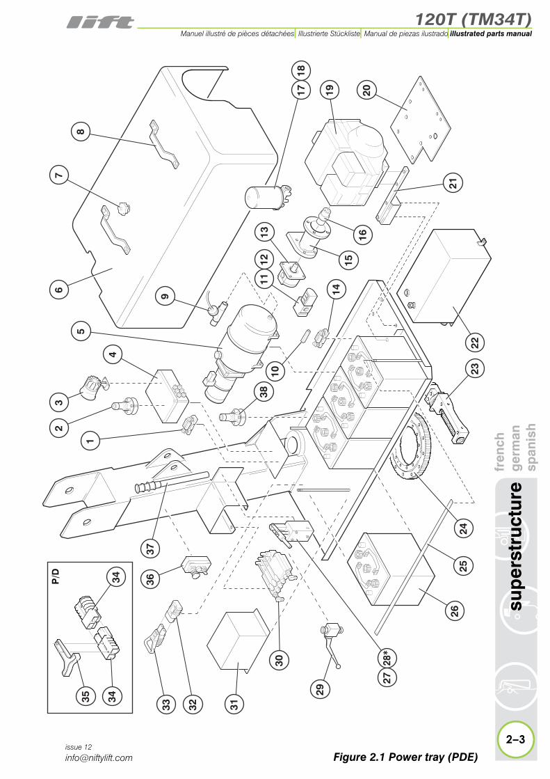
h2.1 Power tray (P/D/E/PE)
Item Description Part Number
1Fuse - 225 A
Fuse holder
P11977
P24708
2 Tilt sensor (OPTIONAL) P16108
3 Siren P11113
4PCB Control boxSee “PCB Control box” on page 2-20.
n/a
5Power packSee “DC Power pack” on page 2-26.
P21690
6Canopy P/D/PE
* Electric(DC)P20555P18279
7 Knob P10186
8 Handle P10241
9 Flow switch(Bi-energy ONLY) P13842
10 Valve - non-return P10107
11 Solenoid valve assy P10132
12 Coil only(Solenoid valve) P70354
13 Pump - 1.6 cc P10655
14Fuse - 125 A
Fuse holder
P12696
P24708
15 Bell housing P12286
16 Coupling Petrol P12287
17 Hydraulic oil filter & bowl assembly P10137
18 Oil filter cartridge P10766
19
Petrol engineGX160GX200
Diesel engineYanmar L48AE
P18916P16934
P12469
20 Mounting plate(Diesel engine ONLY)
P12647
21 Mounting bracket P12641
2–2issue 12
* Not illustrated
120T (TM34T)
fren
chg
erm
ansp
anis
hsu
per
stru
ctur
e
2–3
illustrated parts manualManuel illustré de pièces détachées Illustrierte Stückliste Manual de piezas ilustrado
issue 12
7
8
1718
19
21
20
2423
9
1112
13
1516
10
14
38
29
30
31
2625
22
2
3233
3637
63
15
4
28*
27
3434
35
P/D
Figure 2.1 Power tray (PDE)
120T (TM34T)illustrated parts manual Manuel illustré de pièces détachées Illustrierte Stückliste Manual de piezas ilustrado
uper
stru
ctur
efr
ench
ger
man
span
ish
2.1 continued
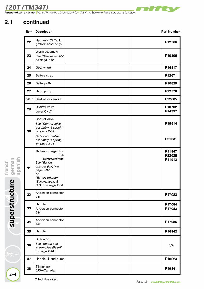
Item Description Part Number
22 Hydraulic Oil Tank (Petrol/Diesel only) P12566
23Worm assemblySee “Slew assembly” on page 2-12.
P19498
24 Gear wheel P16817
25 Battery strap P12671
26 Battery - 6 v P10829
27 Hand pump P22570
28 * Seal kit for item 27 P22605
29Diverter valveLever ONLY
P10702P14397
30
Control valve
See “Control valve assembly (3 spool)” on page 2-14.
Or “Control valve assembly (4 spool)” on page 2-16
P15514
P21631
31
Battery Charger UKUSA
Euro/AustraliaSee “Battery charger (UK)” on page 2-32.or“Battery charger (Euro/Australia & USA)” on page 2-34
P11847P22628P11913
32 Anderson connector24v P17083
33Handle Anderson connector24v
P17084P17083
34 Anderson connector12v P17085
2–4
s
issue 12
35 Handle P16942
36
Button boxSee “Button box assemblies (Base)” on page 2-18.
n/a
37 Handle - Hand pump P10624
38 Tilt sensor (USA/Canada) P19841
* Not illustrated

120T (TM34T)
fren
chg
erm
ansp
anis
hsu
per
stru
ctur
e
2–5
illustrated parts manualManuel illustré de pièces détachées Illustrierte Stückliste Manual de piezas ilustrado
issue 12
7
8
1718
19
21
20
2423
9
1112
13
1516
10
14
38
29
30
31
2625
22
2
3233
3637
63
15
4
28*
27
3434
35
P/D
Figure 2.1 Power tray (PDE)
120T (TM34T)illustrated parts manual Manuel illustré de pièces détachées Illustrierte Stückliste Manual de piezas ilustrado
sup
erst
ruct
ure
fren
chg
erm
ansp
anis
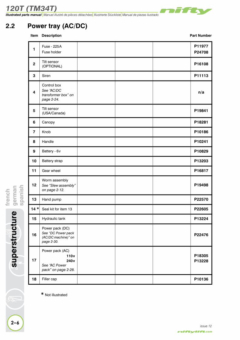
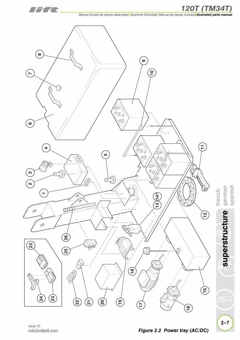
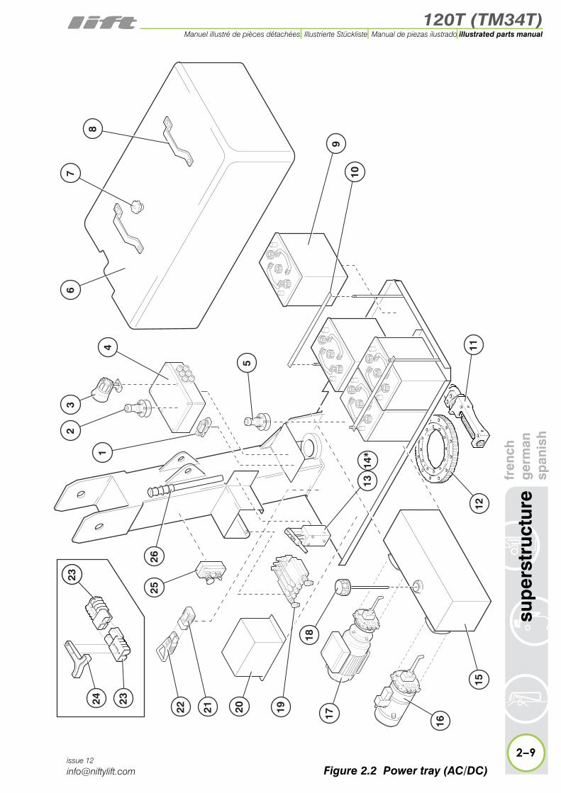
h2.2 Power tray (AC/DC)
Item Description Part Number
1Fuse - 225 A
Fuse holder
P11977
P24708
2 Tilt sensor (OPTIONAL) P16108
3 Siren P11113
4
Control boxSee “AC/DC transformer box” on page 2-24.
n/a
5 Tilt sensor (USA/Canada)
P19841
6 Canopy P18281
7 Knob P10186
8 Handle P10241
9 Battery - 6 v P10829
10 Battery strap P13203
11 Gear wheel P16817
12Worm assemblySee “Slew assembly” on page 2-12.
P19498
13 Hand pump P22570
14 * Seal kit for item 13 P22605
15 Hydraulic tank P13224
16
Power pack (DC)See “DC Power pack (AC/DC machine)” on page 2-30.
P22476
17
Power pack (AC)110 v240 v
See “AC Power pack” on page 2-28.
P18305P13228
18 Filler cap P10136
* Not illustrated
2–6issue 12
120T (TM34T)
fren
chg
erm
ansp
anis
hsu
per
stru
ctur
e
2–7
illustrated parts manualManuel illustré de pièces détachées Illustrierte Stückliste Manual de piezas ilustrado
issue 12
7
8
9
10
11
5
17
20 19
18
16
1512
2
2526
63
14
1314*
2122
2324
23
Figure 2.2 Power tray (AC/DC)

120T (TM34T)illustrated parts manual Manuel illustré de pièces détachées Illustrierte Stückliste Manual de piezas ilustrado
h an ish
2.2 continued
Item Description Part Number
19
Control valve
See “Control valve assembly (3 spool)” on page 2-14.
Or “Control valve assembly (4 spool)” on page 2-16
P15514
P21631
20
Battery Charger UKUSA
Euro/AustraliaSee “Battery charger (UK)” on page 2-32. Or “Battery charger (Euro/Australia & USA)” on page 2-34
P11847P22628P11913
21 Anderson connector24v P17083
22Handle Anderson connector24v
P17084P17083
23 Anderson connector12v P17085
24 Handle P16942
Button box
2–8
sup
erst
ruct
ure
fren
cg
erm
span
issue 12
* Not illustrated
25 See “Button box assemblies (Base)” on page 2-18.
n/a
26 Handle - Hand pump P10624
120T (TM34T)
fren
chg
erm
ansp
anis
hsu
per
stru
ctur
e
2–9
illustrated parts manualManuel illustré de pièces détachées Illustrierte Stückliste Manual de piezas ilustrado
issue 12
7
8
9
10
11
5
17
20 19
18
16
1512
2
2526
63
14
1314*
2122
2324
23
Figure 2.2 Power tray (AC/DC)
120T (TM34T)illustrated parts manual Manuel illustré de pièces détachées Illustrierte Stückliste Manual de piezas ilustrado
2–10
sup
erst
ruct
ure
fren
chg
erm
ansp
anis
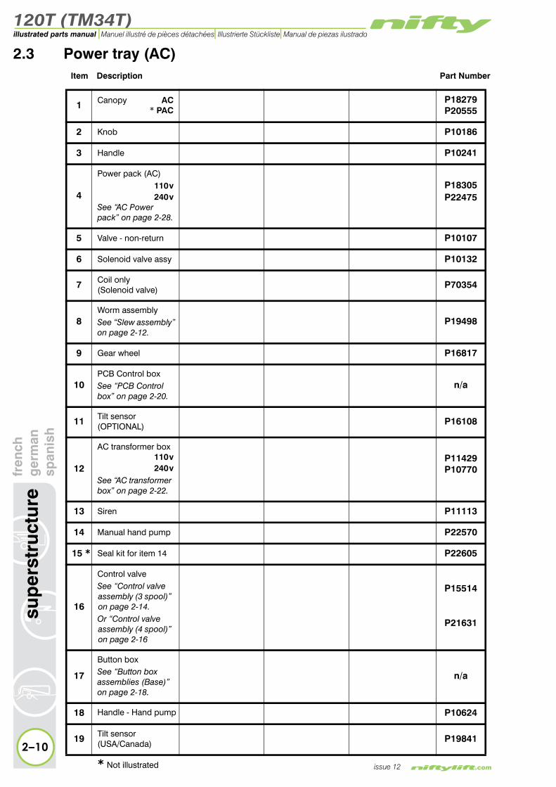
h2.3 Power tray (AC)
Item Description Part Number
1 Canopy AC* PAC
P18279P20555
2 Knob P10186
3 Handle P10241
4
Power pack (AC)110 v240 v
See “AC Power pack” on page 2-28.
P18305P22475
5 Valve - non-return P10107
6 Solenoid valve assy P10132
7 Coil only(Solenoid valve) P70354
8Worm assemblySee “Slew assembly” on page 2-12.
P19498
9 Gear wheel P16817
10PCB Control boxSee “PCB Control box” on page 2-20.
n/a
11 Tilt sensor (OPTIONAL) P16108
12
AC transformer box110 v240 v
See “AC transformer box” on page 2-22.
P11429P10770
13 Siren P11113
14 Manual hand pump P22570
15 * Seal kit for item 14 P22605
16
Control valveSee “Control valve assembly (3 spool)” on page 2-14.Or “Control valve assembly (4 spool)” on page 2-16
P15514
P21631
17
Button boxSee “Button box assemblies (Base)” on page 2-18.
n/a
18 Handle - Hand pump P10624
19 Tilt sensor (USA/Canada) P19841
issue 12* Not illustrated
120T (TM34T)
fren
chg
erm
ansp
anis
hsu
per
stru
ctur
e
2–11
illustrated parts manualManuel illustré de pièces détachées Illustrierte Stückliste Manual de piezas ilustrado
issue 12
2
3
6
8
16
10
11
13
12
17
18
1
4
5
14
9
19
15*
7
21
2120
20 Handle - Anderson P16942
21 Anderson connector12v P17085
Figure 2.3 Power tray (AC)

120T (TM34T)illustrated parts manual Manuel illustré de pièces détachées Illustrierte Stückliste Manual de piezas ilustrado
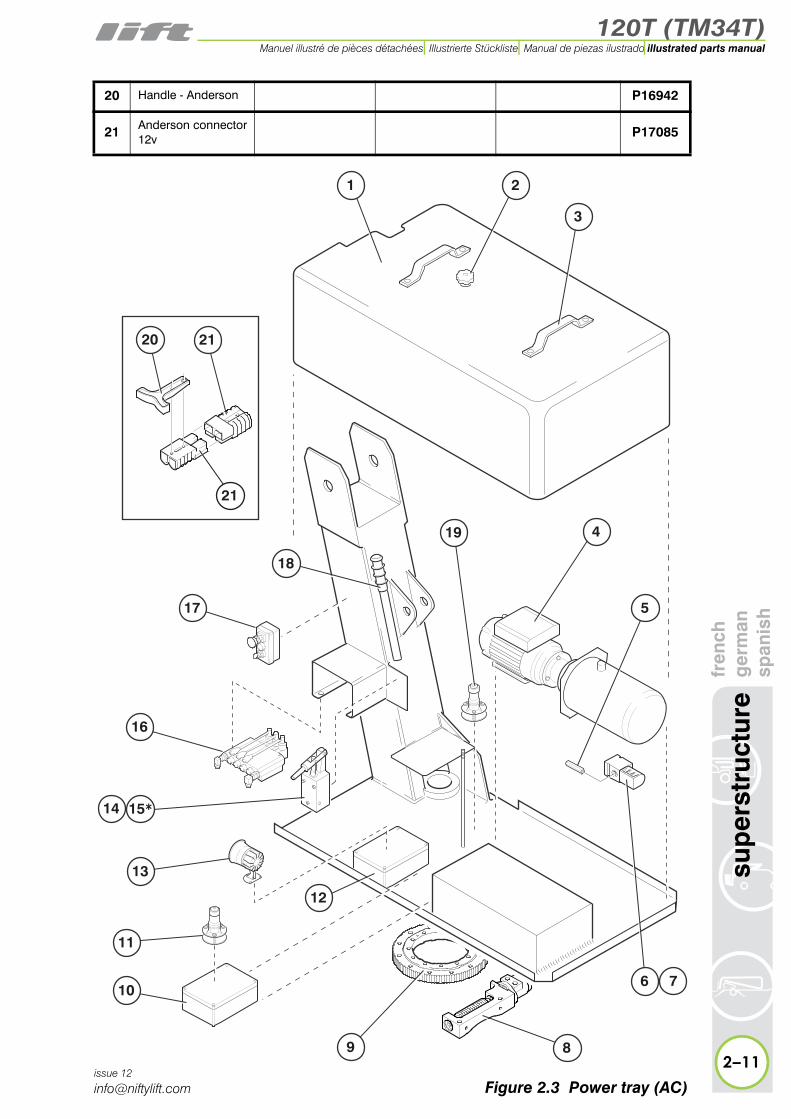
2.4 Slew assemblyItem Description Part Number
Complete assembly(Items 3 to 10 ONLY) P19498
1 Slew guard P20084
2 Slew ring P16817
3 Worm bracket P12681
4 Coupling P12145
5 Spacer P12143
6 Motor P14306
7 * Seal kit for item 6 P13242
8 Bearing P12703
9 Belleville washer P12150
10 Worm gear P14502
2–12
sup
erst
ruct
ure
fren
chg
erm
ansp
anis
h
issue 12
* Not illustrated
120T (TM34T)
fren
chg
erm
ansp
anis
hsu
per
stru
ctur
e
2–13
illustrated parts manualManuel illustré de pièces détachées Illustrierte Stückliste Manual de piezas ilustrado
issue 12
34
5
1
2
8
10
89
9
6 7*
Figure 2.4 Slew assembly
120T (TM34T)illustrated parts manual Manuel illustré de pièces détachées Illustrierte Stückliste Manual de piezas ilustrado
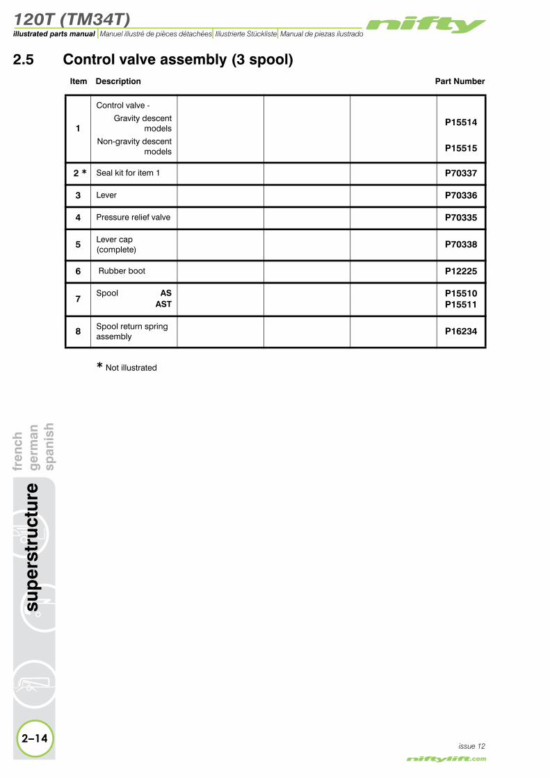
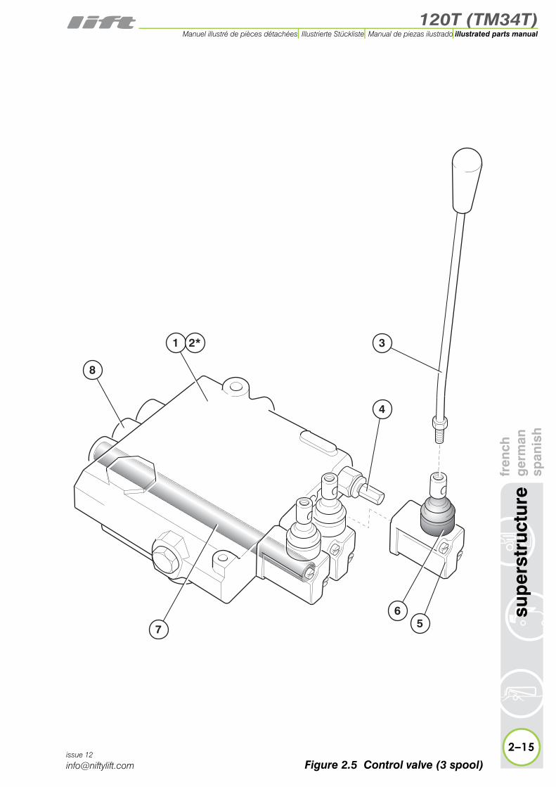
2.5 Control valve assembly (3 spool)Item Description Part Number
1
Control valve -
Gravity descentmodels
Non-gravity descent models
P15514
P15515
2 * Seal kit for item 1 P70337
3 Lever P70336
4 Pressure relief valve P70335
5 Lever cap(complete) P70338
6 Rubber boot P12225
7Spool AS
ASTP15510P15511
8 Spool return spring assembly P16234
* Not illustrated
2–14
sup
erst
ruct
ure
fren
chg
erm
ansp
anis
h
issue 12
120T (TM34T)
fren
chg
erm
ansp
anis
hsu
per
stru
ctur
e
2–15
illustrated parts manualManuel illustré de pièces détachées Illustrierte Stückliste Manual de piezas ilustrado
issue 12
1
8
3
56
7
4
2*
Figure 2.5 Control valve (3 spool)

120T (TM34T)illustrated parts manual Manuel illustré de pièces détachées Illustrierte Stückliste Manual de piezas ilustrado
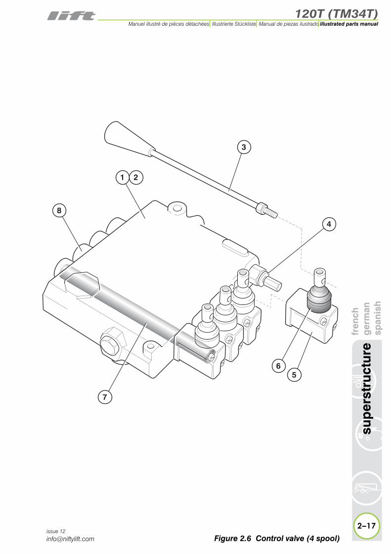
2.6 Control valve assembly (4 spool)Item Description Part Number
1 Control valve P15518
2 * Seal kit for item 1 P70337
3 Lever P70336
4 Pressure relief valve P70335
5 Lever cap(complete) P70338
6 Rubber boot P12225
7 Spool AS P15510
8 Spool return spring assembly P16234
2–16
sup
erst
ruct
ure
fren
chg
erm
ansp
anis
h
issue 12
* Not illustrated
120T (TM34T)
fren
chg
erm
ansp
anis
hsu
per
stru
ctur
e
2–17
illustrated parts manualManuel illustré de pièces détachées Illustrierte Stückliste Manual de piezas ilustrado
issue 12
1
3
56
7
4
2
8
Figure 2.6 Control valve (4 spool)

120T (TM34T)illustrated parts manual Manuel illustré de pièces détachées Illustrierte Stückliste Manual de piezas ilustrado
rstr
uctu
refr
ench
ger
man
span
ish
2.7 Button box assemblies (Base)Item Description Part Number
1E-stop button
USA OnlyP10342P21541
2
(A) Pilot light lens(B) Bulb(C) Lamp holder(D) Lamp housing
P11295P11791P11790P14276
3Key switch - 455 key
2 position P10076
4
Button - GreenBlueBlack
(A) Rubber coverStandardExtended
P10075P11117P10723
P22414P15213
5Button box - 4 hole
50 mm deep80 mm deep
P22417P22416
6Button box - 3 hole
50 mm deep80 mm deep
P22413P22415
7Contact - NC(Used with Item 1and Australian key)
P11839
8Contact - Double NO/NC(Used with item 3)
P16718
9 Contact - Single NO(Used with item 4) P11838
10 Key P70187
2–18
sup
e
issue 12

120T (TM34T)
fren
chg
erm
ansp
anis
hsu
per
stru
ctur
e
2–19
illustrated parts manualManuel illustré de pièces détachées Illustrierte Stückliste Manual de piezas ilustrado
issue 12
6
5
1
4
3
1
2
4
3
1
2
A
B
C
D
3
4
8 97 10
A
Figure 2.7 Button boxes

120T (TM34T)illustrated parts manual Manuel illustré de pièces détachées Illustrierte Stückliste Manual de piezas ilustrado
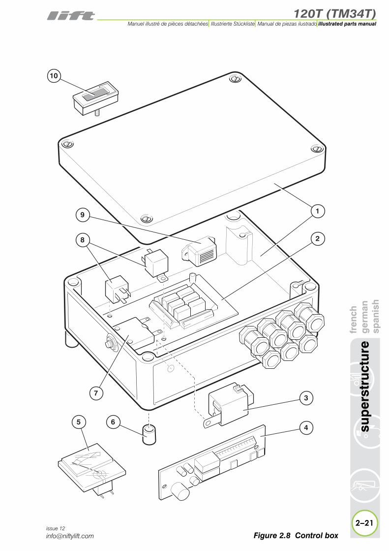
2.8 PCB Control boxItem Description Part Number
1 ABS Box P12498
2 PCB P14033
3 Timer relay(Diesel only) P10664
4PCB -12 v (Battery management - OPTIONAL)
P11174
5 Battery meter(OPTIONAL) P11494
6 Nylon spacer P11863
7 Circuit breaker - 15 A P11050
8 Relay P10340
9 Buzzer P10341
10 Hour meter(OPTIONAL) P11410
2–20
sup
erst
ruct
ure
fren
chg
erm
ansp
anis
h
issue 12
120T (TM34T)
fren
chg
erm
ansp
anis
hsu
per
stru
ctur
e
2–21
illustrated parts manualManuel illustré de pièces détachées Illustrierte Stückliste Manual de piezas ilustrado
issue 12
1
2
5 6
8
9
73
4
10
Figure 2.8 Control box

120T (TM34T)illustrated parts manual Manuel illustré de pièces détachées Illustrierte Stückliste Manual de piezas ilustrado
2.9 AC transformer boxItem Description Part Number
1Complete assembly
240 v
110 v
P10770
P11429
2Fuse 16 A (240 v)
25 A (110 v)P11767P14040
3 Fuse 3.15 A P15504
4PCB assembly
240 v110 v
P10847P14039
5 Hour meter (OPTIONAL) P11410
6 Siren P11113
2–22
sup
erst
ruct
ure
fren
chg
erm
ansp
anis
h
issue 12

120T (TM34T)
fren
chg
erm
ansp
anis
hsu
per
stru
ctur
e
2–23
illustrated parts manualManuel illustré de pièces détachées Illustrierte Stückliste Manual de piezas ilustrado
issue 12
�
�
�
�
�
�
Figure 2.9 AC transformer box
120T (TM34T)illustrated parts manual Manuel illustré de pièces détachées Illustrierte Stückliste Manual de piezas ilustrado
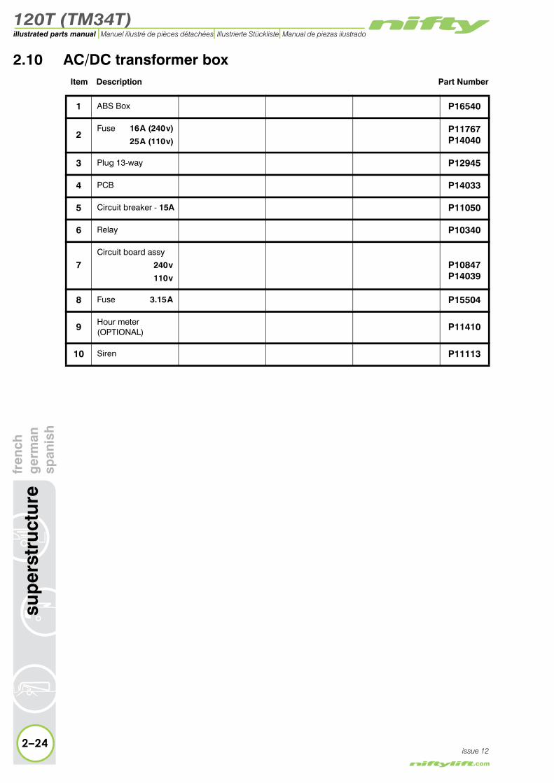
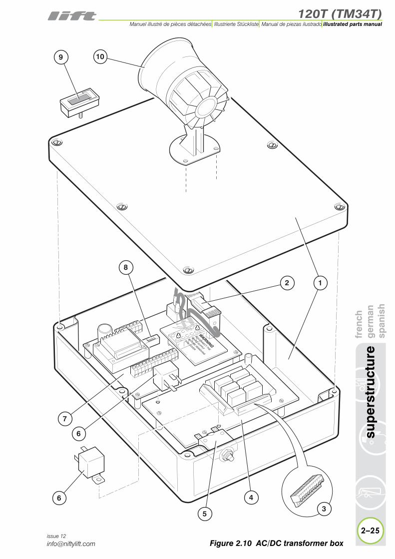
2.10 AC/DC transformer boxItem Description Part Number
1 ABS Box P16540
2Fuse 16 A (240 v)
25 A (110 v)P11767P14040
3 Plug 13-way P12945
4 PCB P14033
5 Circuit breaker - 15A P11050
6 Relay P10340
7Circuit board assy
240 v
110 v
P10847P14039
8 Fuse 3.15 A P15504
9 Hour meter (OPTIONAL) P11410
10 Siren P11113
2–24
sup
erst
ruct
ure
fren
chg
erm
ansp
anis
h
issue 12
120T (TM34T)
fren
chg
erm
ansp
anis
hsu
per
stru
ctur
e
2–25
illustrated parts manualManuel illustré de pièces détachées Illustrierte Stückliste Manual de piezas ilustrado
issue 12
3
2
6
1
7
6
5
4
8
9 10
Figure 2.10 AC/DC transformer box
120T (TM34T)illustrated parts manual Manuel illustré de pièces détachées Illustrierte Stückliste Manual de piezas ilustrado
fren
chg
erm
ansp
anis
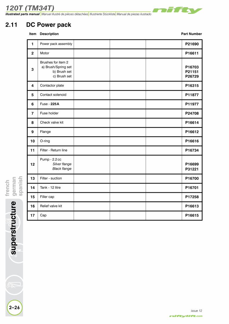
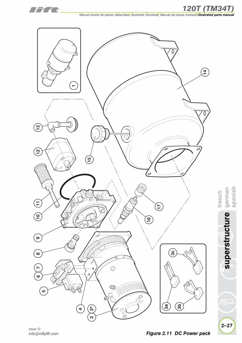
h2.11 DC Power pack
Item Description Part Number
1 Power pack assembly P21690
2 Motor P16611
3
Brushes for item 2a) Brush/Spring set
b) Brush setc) Brush set
P16703P21151P26729
4 Contactor plate P16315
5 Contact solenoid P11877
6 Fuse - 225 A P11977
7 Fuse holder P24708
8 Check valve kit P16614
9 Flange P16612
10 O-ring P16616
11 Filter - Return line P16734
12Pump - 2.2 cc
Silver flangeBlack flange
P16699P31221
13 Filter - suction P16700
14 Tank - 12 litre P16701
15 Filler cap P17258
2–26
sup
erst
ruct
ure
issue 12
16 Relief valve kit P16613
17 Cap P16615
120T (TM34T)
fren
chg
erm
ansp
anis
hsu
per
stru
ctur
e
2–27
illustrated parts manualManuel illustré de pièces détachées Illustrierte Stückliste Manual de piezas ilustrado
issue 12
14
1112
139
108
16
17
15
1
23*
56
7
4 3a 3b3c
Figure 2.11 DC Power pack

120T (TM34T)illustrated parts manual Manuel illustré de pièces détachées Illustrierte Stückliste Manual de piezas ilustrado
erst
ruct
ure
fren
chg
erm
ansp
anis
h2.12 AC Power pack
Item Description Part Number
1
Power pack assembly110 v240 v
AC/DC Only
P18305P22475P13228
2 * Seal kit for item 1 P70171
3 Flange coupling kit P10848
4 Coupling P24949
5 Relief valve P70158
6 Check valve P70159
7 ‘O’ Ring(Tank/Power pack) P15303
8 Filter - Return line P70247
9 Tank - 9 litre P10862
10 Filler cap P21215
11 ‘O’ Ring(Backplate/Tank) P17749
12 Filter - suction P70155
13 Pump - 1.5 cc P22881
14 Non-return valve - 1/4in P10107
15Solenoid valve assyCoil ONLY
P10132P70354
16 Motor - 220/240 v AC P13848
17 Run capacitor P12702
18 Start capacitor P12701
2–28
sup
issue 12
* Not illustrated Note: Items 9, 10 and 11 are NOT applicable to AC/DC machine

120T (TM34T)
fren
chg
erm
ansp
anis
hsu
per
stru
ctur
e
2–29
illustrated parts manualManuel illustré de pièces détachées Illustrierte Stückliste Manual de piezas ilustrado
issue 12
10
16
13
11
14
12
57
8
18
17
3
9
4
6
12*
15
Figure 2.12 AC Power pack
120T (TM34T)illustrated parts manual Manuel illustré de pièces détachées Illustrierte Stückliste Manual de piezas ilustrado
ench
rman
anis
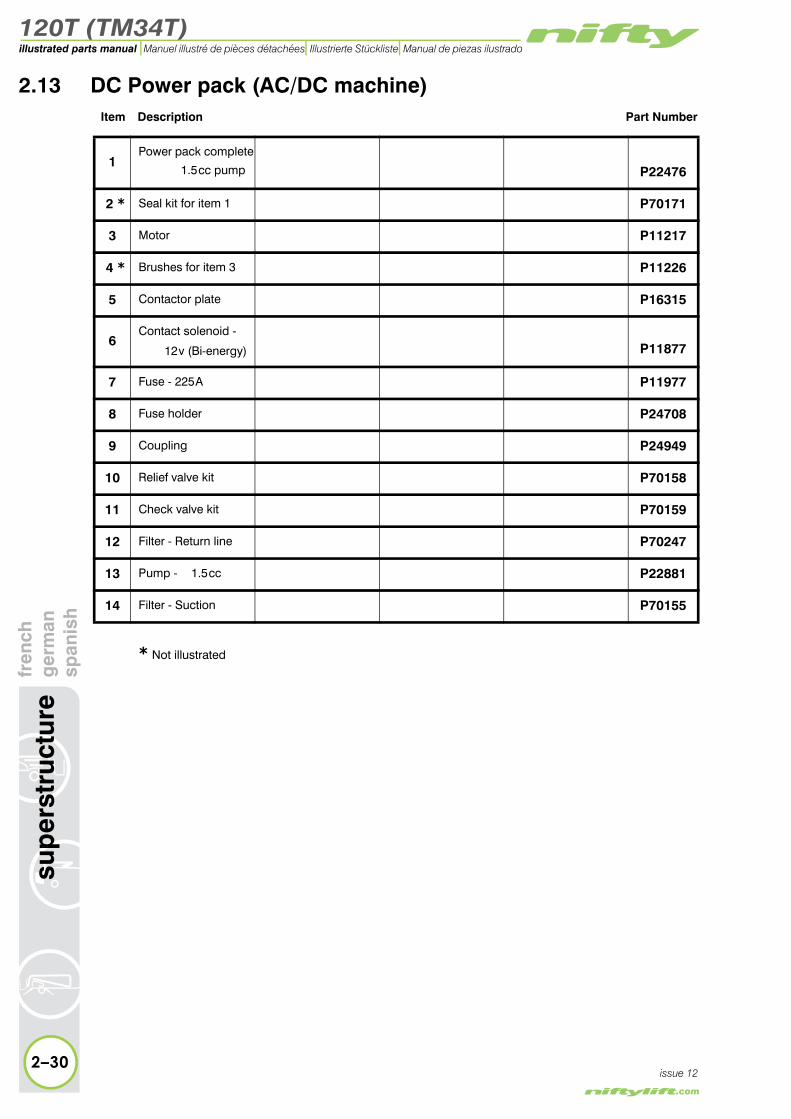
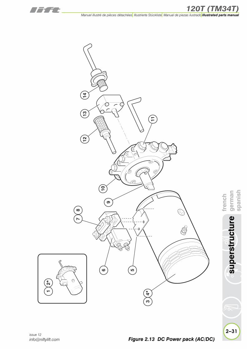
h2.13 DC Power pack (AC/DC machine)
Item Description Part Number
1Power pack complete
1.5 cc pump P22476
2 * Seal kit for item 1 P70171
3 Motor P11217
4 * Brushes for item 3 P11226
5 Contactor plate P16315
6Contact solenoid -
12 v (Bi-energy) P11877
7 Fuse - 225 A P11977
8 Fuse holder P24708
9 Coupling P24949
10 Relief valve kit P70158
11 Check valve kit P70159
12 Filter - Return line P70247
13 Pump - 1.5 cc P22881
14 Filter - Suction P70155
* Not illustrated
2–30
sup
erst
ruct
ure
fr ge
sp
issue 12
120T (TM34T)
fren
chg
erm
ansp
anis
hsu
per
stru
ctur
e
2–31
illustrated parts manualManuel illustré de pièces détachées Illustrierte Stückliste Manual de piezas ilustrado
issue 12
34*
6 5
78
10
1213
14
9
11
12*
Figure 2.13 DC Power pack (AC/DC)

120T (TM34T)illustrated parts manual Manuel illustré de pièces détachées Illustrierte Stückliste Manual de piezas ilustrado
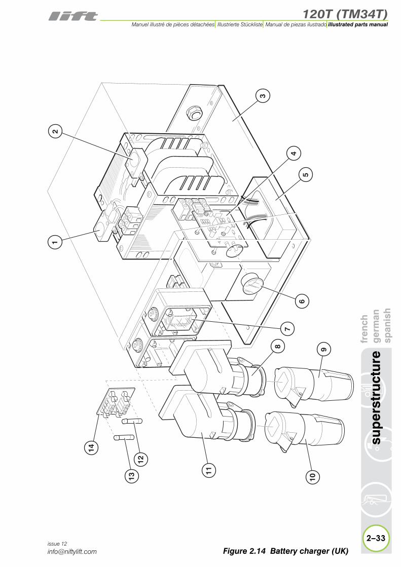
2.14 Battery charger (UK)Item Description Part Number
1 Thermal cut-out - 240 v P15269
2 Thermal cut-out - 110 v P15268
3 Charger complete P11847
4 PCB P70091
5 Thyristor module P14993
6 Lens P11104
7 Relay P12879
8 Socket - 110 v P10750
9 Plug - 110 v P10724
10 Plug - 240 v P10268
11 Socket - 240 v P10174
12 Fuse - 5A P15022
13 Fuse - 10 A P11934
14 Fuse board P14386
2–32
sup
erst
ruct
ure
fren
chg
erm
ansp
anis
h
issue 12
120T (TM34T)
fren
chg
erm
ansp
anis
hsu
per
stru
ctur
e
2–33
illustrated parts manualManuel illustré de pièces détachées Illustrierte Stückliste Manual de piezas ilustrado
issue 12
21
47
3
5
98
10
11
13
14
12
6
Figure 2.14 Battery charger (UK)
120T (TM34T)illustrated parts manual Manuel illustré de pièces détachées Illustrierte Stückliste Manual de piezas ilustrado
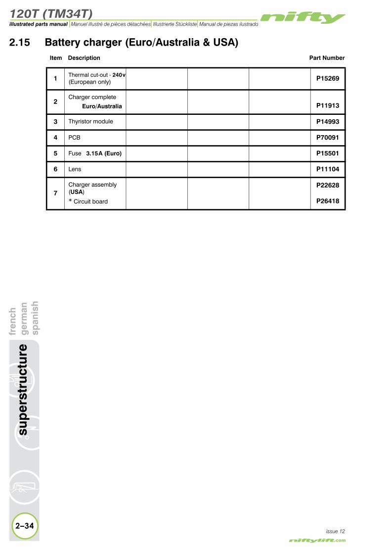
2.15 Battery charger (Euro/Australia & USA)Item Description Part Number
1 Thermal cut-out - 240 v(European only) P15269
2Charger complete
Euro/Australia P11913
3 Thyristor module P14993
4 PCB P70091
5 Fuse 3.15 A (Euro) P15501
6 Lens P11104
7Charger assembly (USA)
* Circuit board
P22628
P26418
2–34
sup
erst
ruct
ure
fren
chg
erm
ansp
anis
h
issue 12

120T (TM34T)
fren
chg
erm
ansp
anis
hsu
per
stru
ctur
e
2–35
illustrated parts manualManuel illustré de pièces détachées Illustrierte Stückliste Manual de piezas ilustrado
issue 12
1
2
3
6
5
4
7
Figure 2.15 Battery charger (Euro/Aus & USA)

120T (TM34T)
3
illustrated parts manualManuel illustré de pièces détachéesIllustrierte StücklisteManual de piezas ilustrado
boom assembliesfrench
germanspanish

120T (TM34T)illustrated parts manual Manuel illustré de pièces détachées Illustrierte Stückliste Manual de piezas ilustrado
bo
om
ass
emb
lies
fren
chg
erm
ansp
anis
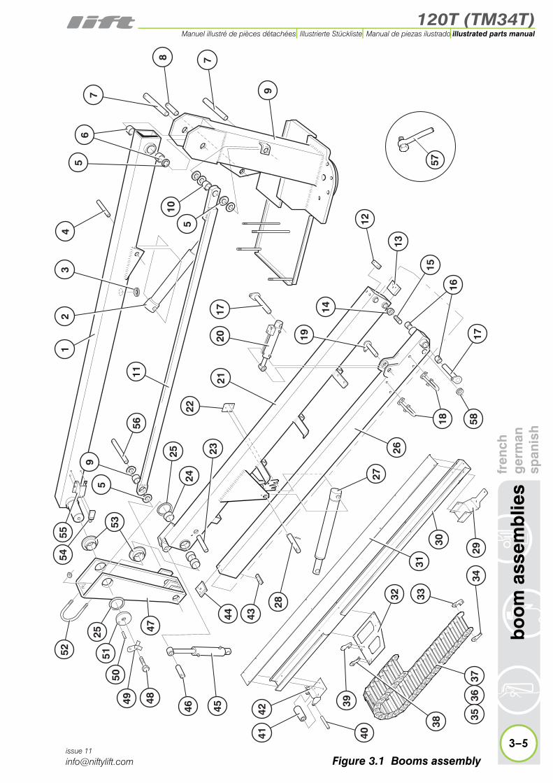
h3.1 Booms assembly
Item Description Part Number
1 Boom 2 P20033
2Lift cylinderSee “Lift cylinder” on page 3-6.
P17989
3 Grommet P11283
4 Pivot pin - 200 mm P15950
5 Plastic washer P10035
6 Bush DU2550 P10031
7 Pivot pin - 240mm P19546
8 Pivot pin - 94mm P12953
9 Boom 1 P20025
10 Bush DU2520 P10032
11 Levelling rod P20048
12 Wear pad P15899
13 Wear pad (Black) P22653
14 Nut P16312
15 Nylatron stud P11436
16 Bush DU2525 P10034
17 Pivot pin - 192mm P10210
18 Hose hoop P11118
19 Pivot pin - 95mm P12899
20Levelling cylinderSee “Levelling cylin-der” on page 3-8.
P22974
21 Boom 3 P22613
22 Bracket - Boom latch P20049
23 Pivot pin - 127mm P12952
24 Bush DU7050 P12324
25 Nylatron washer P12733
26 Boom 4 P10423
27Lift cylinderSee “Lift cylinder” on page 3-6.
P18323
28Pivot pin - 146 mmRoll pin
P19548P17485
29 Bracket - Trunking to P19915
3–2issue 11Boom 4

120T (TM34T)
fren
chg
erm
ansp
anis
hb
oo
m a
ssem
blie
s
3–3
illustrated parts manualManuel illustré de pièces détachées Illustrierte Stückliste Manual de piezas ilustrado
issue 11
12
4
11
22
59
21
33
56
24
25
53
10
5
53
6
8 7
9
12
13
14
18 58
26
4027
39
44 43
30
2937
34
32
31
4142
38
3635
15
16
17
28
2345
5455
46
4748
52
25
5049
517
192017
57
Figure 3.1 Booms assembly

120T (TM34T)illustrated parts manual Manuel illustré de pièces détachées Illustrierte Stückliste Manual de piezas ilustrado
bo
om
ass
emb
lies
fren
chg
erm
ansp
anis
h3.1 continued
Item Description Part Number
30 Trunking P20167
31 Lid - Trunking P20168
32 Bracket - Trunking to tracking P12643
33 Lower bracket - Inner P19228
34 Lower bracket - Outer P19227
35TrackingSee “Energy chain” on page 3-12.
N/A
36 Tracking link N/A
37 Tracking bridge N/A
38 Upper bracket - Outer P19229
39 Upper bracket - Inner P19230
40 Roller pin - 126 mm P10682
41 Roller P10680
42 Roller bracket P20169
43 Spacer P10601
44 Wear pad (Red) P10519
45Levelling cylinderSee “Levelling cylin-der” on page 3-8.
P11764
46 Pivot pin - 85 mm P19550
47 Knuckle P20044
48 Bolt for item 51 P70266
49 Tab washer P17412
50 Roll pin for item 51 P70267
51 End cap P10037
52 Hose hoop P10566
53 Flanged bush P12719
54 Micro switch P24994
55 Bracket P20563
56 Pivot pin - 253 mm P19551
57Swing bolt(Used with items 4, 7, 8, 23, 28, 46 & 56)
P15966
3–4issue 11
58 Grommet P17566
120T (TM34T)
fren
chg
erm
ansp
anis
hb
oo
m a
ssem
blie
s
3–5
illustrated parts manualManuel illustré de pièces détachées Illustrierte Stückliste Manual de piezas ilustrado
issue 11
12
4
11
22
59
21
33
56
24
25
53
10
5
53
6
8 7
9
12
13
14
18 58
26
4027
39
44 43
30
2937
34
32
31
4142
38
3635
15
16
17
28
2345
5455
46
4748
52
25
5049
517
192017
57
Figure 3.1 Booms assembly
120T (TM34T)illustrated parts manual Manuel illustré de pièces détachées Illustrierte Stückliste Manual de piezas ilustrado
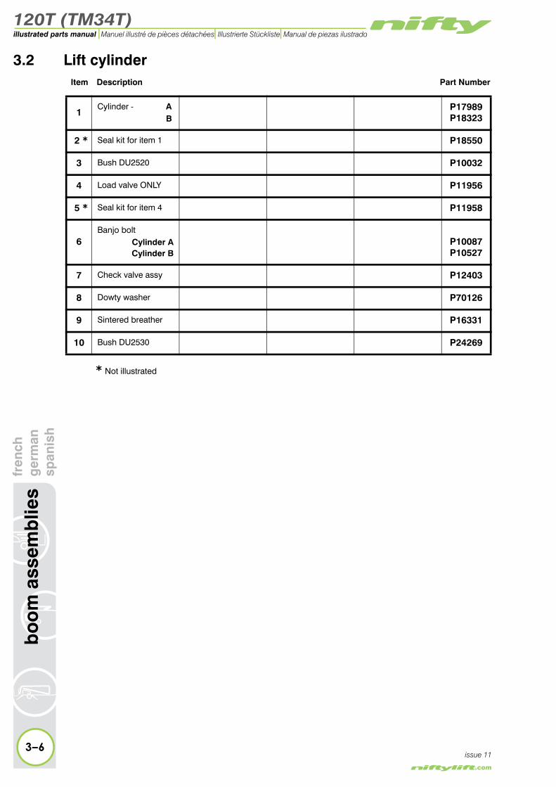
3.2 Lift cylinderItem Description Part Number
1Cylinder - A
BP17989P18323
2 * Seal kit for item 1 P18550
3 Bush DU2520 P10032
4 Load valve ONLY P11956
5 * Seal kit for item 4 P11958
6Banjo bolt
Cylinder ACylinder B
P10087P10527
7 Check valve assy P12403
8 Dowty washer P70126
9 Sintered breather P16331
10 Bush DU2530 P24269
3–6
bo
om
ass
emb
lies
fren
chg
erm
ansp
anis
h
issue 11
* Not illustrated

120T (TM34T)
fren
chg
erm
ansp
anis
hb
oo
m a
ssem
blie
s
3–7
illustrated parts manualManuel illustré de pièces détachées Illustrierte Stückliste Manual de piezas ilustrado
issue 11
5*
CYLINDER A
CYLINDER B
1
3
3
10
4
6
7
8
2*
9
Figure 3.2 Lift cylinder

120T (TM34T)illustrated parts manual Manuel illustré de pièces détachées Illustrierte Stückliste Manual de piezas ilustrado
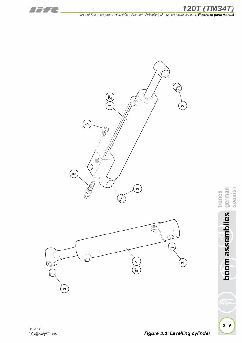
3.3 Levelling cylinderItem Description Part Number
1 Cylinder (slave) P22974
2 * Seal kit foritems 1 and 4 P11082
3 Bush DU2520 P10032
4 Cylinder P11764
5 Load valve P11956
6 Check valvecartridge P17317
3–8
bo
om
ass
emb
lies
fren
chg
erm
ansp
anis
h
issue 11
* Not illustrated
120T (TM34T)
fren
chg
erm
ansp
anis
hb
oo
m a
ssem
blie
s
3–9
illustrated parts manualManuel illustré de pièces détachées Illustrierte Stückliste Manual de piezas ilustrado
issue 11
�
�
�
�
��
��
��
��
Figure 3.3 Levelling cylinder
120T (TM34T)illustrated parts manual Manuel illustré de pièces détachées Illustrierte Stückliste Manual de piezas ilustrado
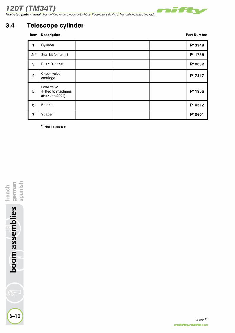
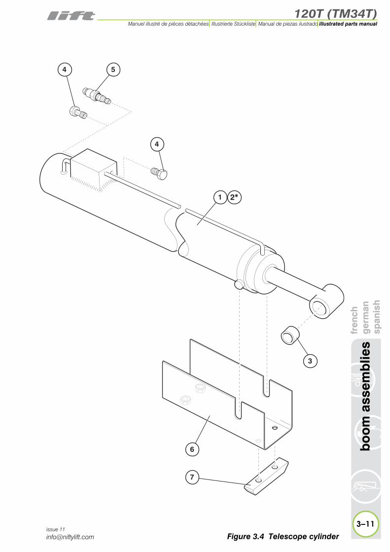
3.4 Telescope cylinderItem Description Part Number
1 Cylinder P13348
2 * Seal kit for item 1 P11756
3 Bush DU2520 P10032
4 Check valvecartridge P17317
5Load valve(Fitted to machinesafter Jan 2004)
P11956
6 Bracket P10512
7 Spacer P10601
3–10
bo
om
ass
emb
lies
fren
chg
erm
ansp
anis
h
issue 11
* Not illustrated
120T (TM34T)
fren
chg
erm
ansp
anis
hb
oo
m a
ssem
blie
s
3–11
illustrated parts manualManuel illustré de pièces détachées Illustrierte Stückliste Manual de piezas ilustrado
issue 11
1
54
4
3
2*
6
7
Figure 3.4 Telescope cylinder

120T (TM34T)illustrated parts manual Manuel illustré de pièces détachées Illustrierte Stückliste Manual de piezas ilustrado
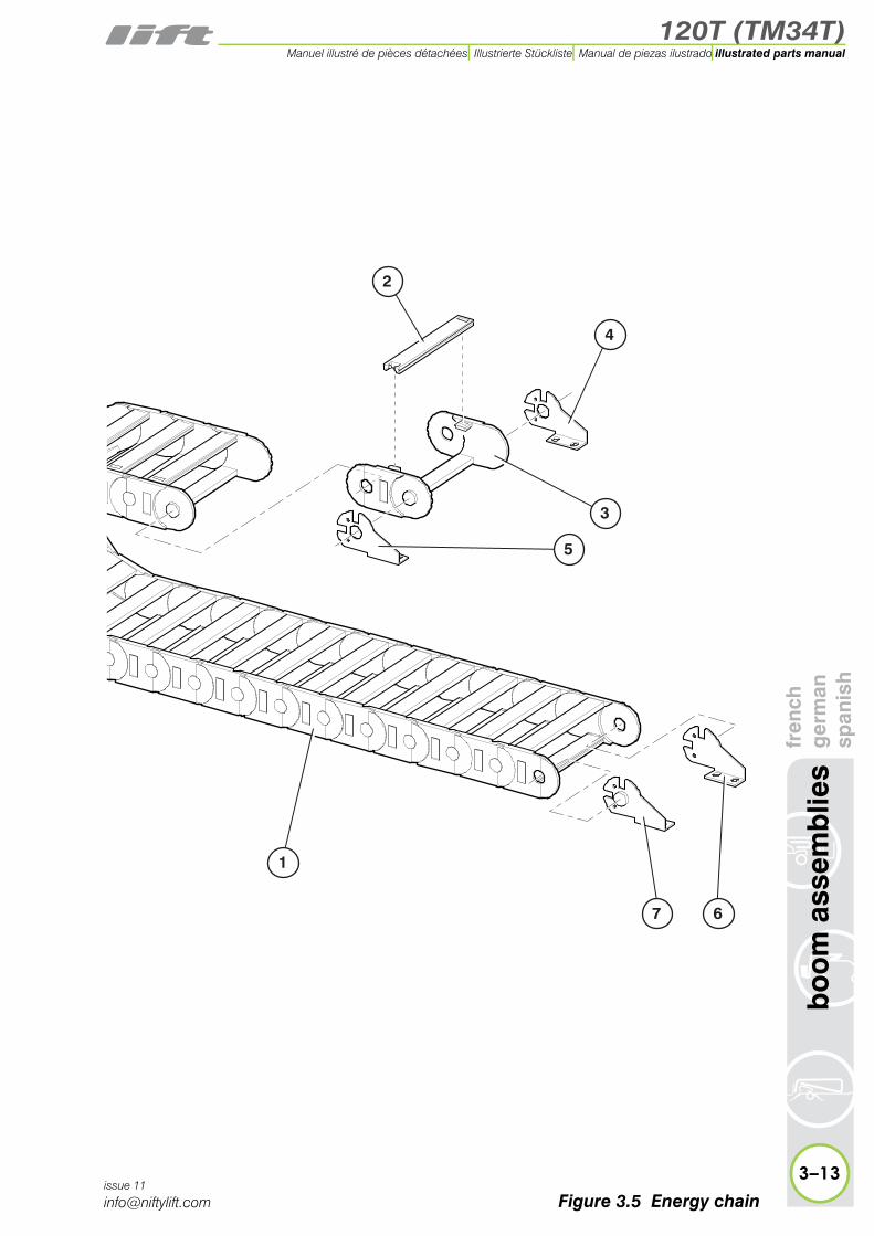
3.5 Energy chainItem Description Part Number
1Chain assembly(Items 4 to 7 not included)
Refer to Item 2 or 3 for identification
P19225or
P27397
2Bridge
Ref. 275.15Ref. 27000.15
Chain AssemblyP19225P27397
P15813P28094
3Link (Includes item 2)
* Ref. 27.15.100.0* Ref. 2700.15.100.0
Chain AssemblyP19225P27397
P15814P28093
4 Bracket(Inner, with hole) P19228
5 Bracket(Outer, with hole) P19227
6 Bracket (Inner) P19230
3–12
bo
om
ass
emb
lies
fren
chg
erm
ansp
anis
h
issue 11
7 Bracket (Outer) P19229
* As moulded/stamped on component
120T (TM34T)
fren
chg
erm
ansp
anis
hb
oo
m a
ssem
blie
s
3–13
illustrated parts manualManuel illustré de pièces détachées Illustrierte Stückliste Manual de piezas ilustrado
issue 11
2
7
4
5
3
6
1
Figure 3.5 Energy chain

120T (TM34T)
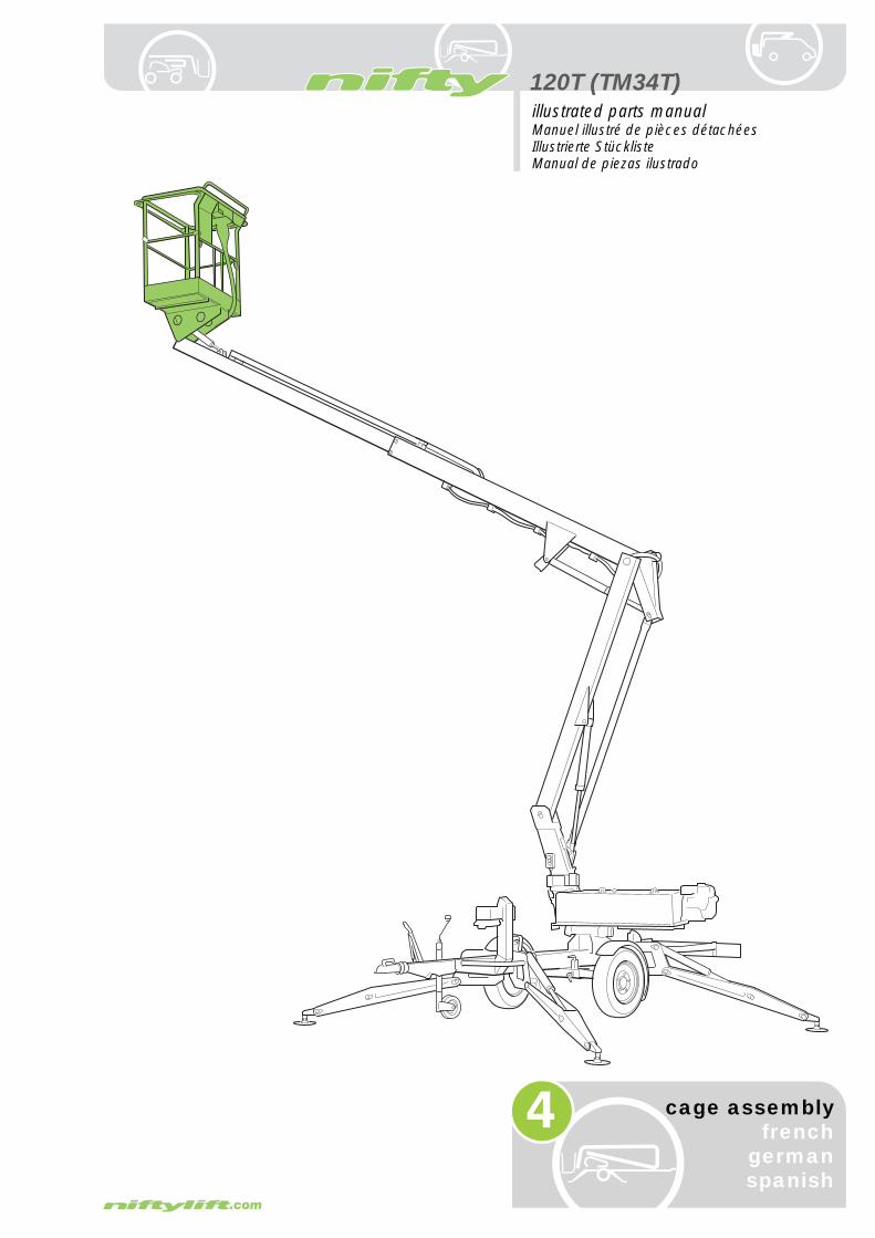
4
illustrated parts manualManuel illustré de pièces détachéesIllustrierte StücklisteManual de piezas ilustrado
cage assemblyfrench
germanspanish

120T (TM34T)illustrated parts manual Manuel illustré de pièces détachées Illustrierte Stückliste Manual de piezas ilustrado
mb
lyfr
ench
ger
man
span
ish
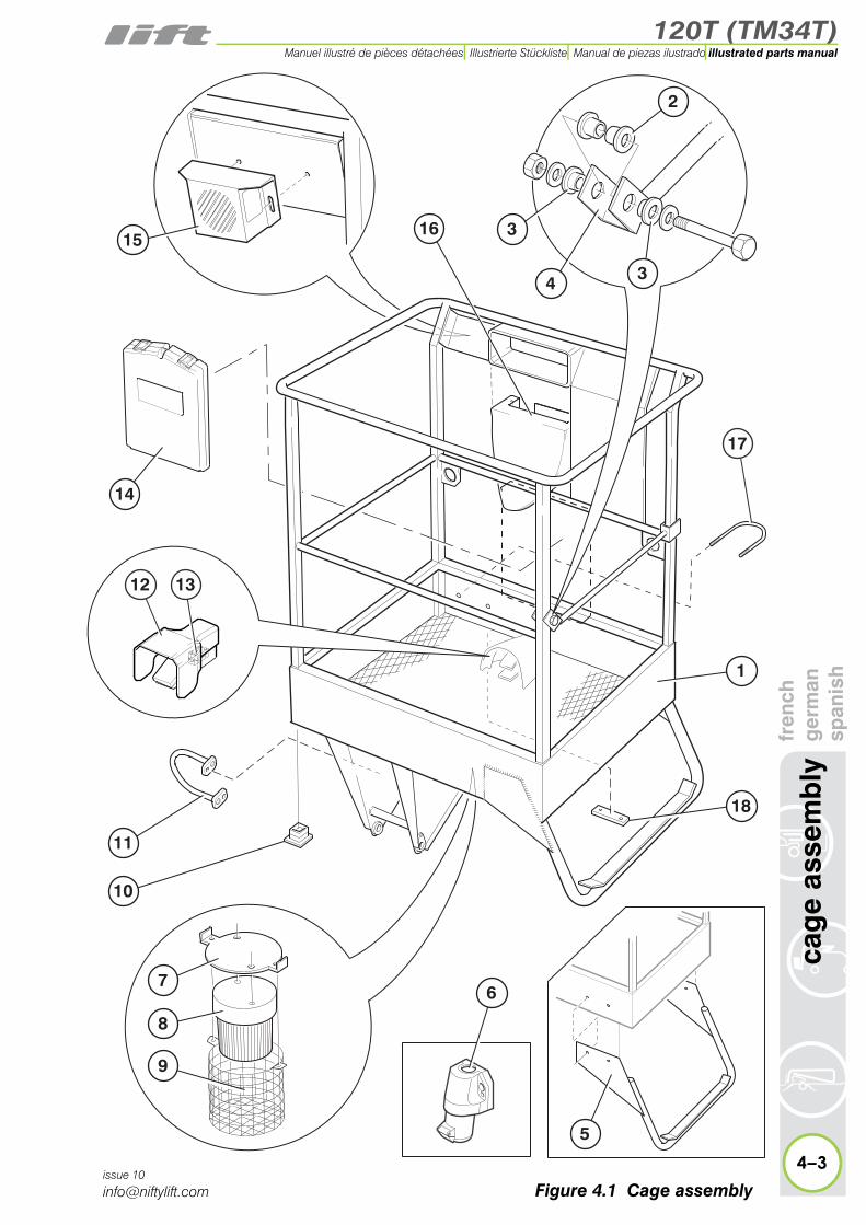
4.1 Cage assemblyItem Description Part Number
1
Cage - With Cage Weigh
SpringLoad Cell
Non Cage Weigh
TM34T (USA)
P17939P17050P12768P12768
2 Bush P10840
3 Bush P18647
4 Cage gate P11610
5 Step(Cage weigh ONLY) P16905
6Socket - 110v/16A(OPTIONAL)
P25082
7 Bracket - Beacon (OPTIONAL) P11451
8 Beacon (OPTIONAL) P10274
9 Guard - Beacon (OPTIONAL) P10312
10 Cap P10841
11 Hoop P11118
12Footswitch(OPTIONAL)Cover ONLY
P26601
P26752
13 Electrical contact P26751
Instruction manual
4–2
cag
e as
se
issue 10
14 box (OPTIONAL) P11618
15 Annunciator(OPTIONAL) P13836
16 Hoop (U Bolt) P10566
17Wear Pad(Non cage weigh/USA only)
P15167
120T (TM34T)
fren
chg
erm
ansp
anis
hca
ge
asse
mb
ly
4–3
illustrated parts manualManuel illustré de pièces détachées Illustrierte Stückliste Manual de piezas ilustrado
issue 10
1
18
10
16
11
7
8
14
9
5
3
4
2
3
15
13
17
12
6
Figure 4.1 Cage assembly

120T (TM34T)illustrated parts manual Manuel illustré de pièces détachées Illustrierte Stückliste Manual de piezas ilustrado
cag
e as
sem
bly
fren
chg
erm
ansp
anis
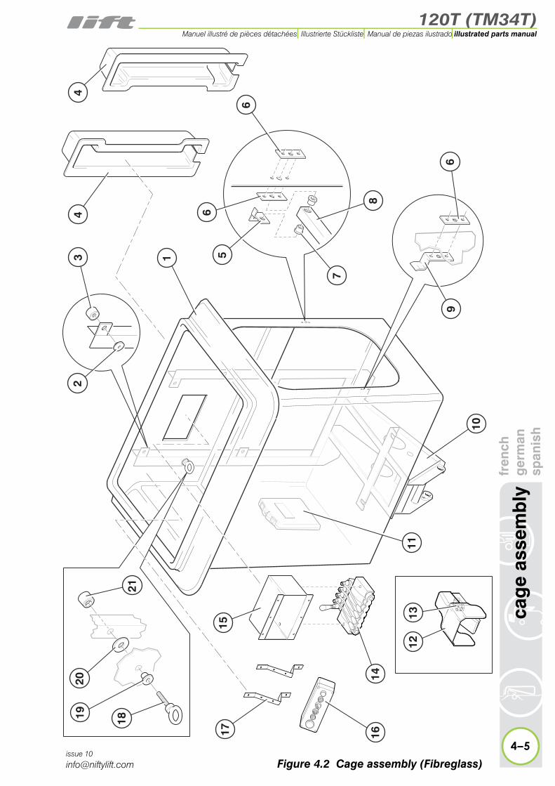
h4.2 Cage assembly (Fibreglass)
Item Description Part Number
1 Cage RH entry P10973
2 Bolt insulator P11606
3 Insulator cup P11607
4 Frame cover P12213
5 Gate plate (angled) P18661
6 Gate plate P11063
7 Bush P10840
8 Cage gate P11061
9 Gate rest plate (inner) P11062
10
Mounting frameNon cage weigh
* Cage weigh (LC)* (Spring)
P10944P17551P18241
11 Instruction manual box P11618
12Footswitch(OPTIONAL)Cover ONLY
P26601
P26752
13 Electrical contact P26751
14
Control valveSee “Control valve assembly (Cage)” on page 4-10.
P15521
15 Mounting bracket P12857
16
Button boxSee “Button box assemblies (Cage)” on page 4-12.
N/A
17 Bracket for item 16 P12612
18 Eye bolt (M16) N/A
19 Bolt insulator P11533
20 Insulator spacer P11608
21 Insulator cup P11534
4–4issue 10
* Not illustrated
120T (TM34T)
fren
chg
erm
ansp
anis
hca
ge
asse
mb
ly
4–5
illustrated parts manualManuel illustré de pièces détachées Illustrierte Stückliste Manual de piezas ilustrado
issue 10
1312
34
16
11
14
4
6
8
6
1
21
10
2
56
9
7
2019 18
1715
Figure 4.2 Cage assembly (Fibreglass)

120T (TM34T)illustrated parts manual Manuel illustré de pièces détachées Illustrierte Stückliste Manual de piezas ilustrado
ass
emb
lyfr
ench
ger
man
span
ish
4.3 Cage weigh assembly (Spring)Item Description Part Number
1 Pivot pin - 274mm P17942
2 Washer P18058
3 Grommet P14456
4 Bearing P18080
5 Distance tube P17975
6 Distance tube P17974
7 Inner frame P17937
8 Spring P18079
9 Pivot pin - 208mm P17940
10 Pivot pin - 251mm P17941
11 Swivel arm P17938
12 Distance tube P17944
13 Outer frame P17936
14 Microswitch P18150
15 Washer P10035
16 Pivot pin - 192mm P10210
17Levelling cylinderSee “Levelling cylin-der” on page 3-8.
P22974
18 Pivot pin - 182mm P10029
19 Pivot pin - 110mm P13157
20 Box P11910
21 PCB - Cage Weigh P16164
4–6
cag
e
issue 10

120T (TM34T)
fren
chg
erm
ansp
anis
hca
ge
asse
mb
ly
4–7
illustrated parts manualManuel illustré de pièces détachées Illustrierte Stückliste Manual de piezas ilustrado
issue 10
2
4
2
2
6
7
14
8
4
2
13
11
2
1
32021 2
9
10
12
4
17 16
15
15
4
5
11
19 18
Figure 4.3 Cage weigh assembly (Spring)

120T (TM34T)illustrated parts manual Manuel illustré de pièces détachées Illustrierte Stückliste Manual de piezas ilustrado
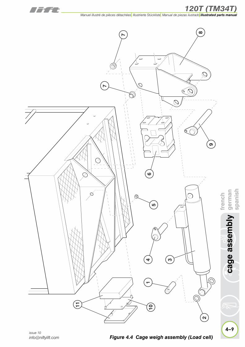
4.4 Cage weigh assembly (Load Cell)Item Description Part Number
1 Pin - 110mm P13157
2 Washer - plastic P10035
3Levelling cylinderSee “Levelling cylin-der” on page 3-8.
P22974
4 Pin - 95mm P12899
5 Grommet P14456
6Load cell
1.1m cable2.4m cable
P18179P29179
7 Rubber grommet P16983
8 Lower chassis P16866
9 Pin - 192mm P10210
4–8
cag
e as
sem
bly
fren
chg
erm
ansp
anis
h
issue 10
10 PCB - 2000kg12v P18185
11 Box assembly P17133
120T (TM34T)
fren
chg
erm
ansp
anis
hca
ge
asse
mb
ly
4–9
illustrated parts manualManuel illustré de pièces détachées Illustrierte Stückliste Manual de piezas ilustrado
issue 10
87
4
9
65
2
3
11
1
7
10
Figure 4.4 Cage weigh assembly (Load cell)

120T (TM34T)illustrated parts manual Manuel illustré de pièces détachées Illustrierte Stückliste Manual de piezas ilustrado
4.5 Control valve assembly (Cage)Item Description Part Number
1 Lever (Levelling) P70347
2Spool AS
ASTP15510P15511
3 Valve seal kit P10707
4 Spool return spring assembly P16234
5 Interface seal kit P10706
6 Lever (150mm) P70346
7Valve assembly -
5 spool P15521
8
Pressure relief valveTelescope spoolLevelling spool
Boom 3 spool
P10879P10879P15840
9 Pressure relief valve P70335
10 Lever cap P70338
11 Rubber boot P12225
4–10
cag
e as
sem
bly
fren
chg
erm
ansp
anis
h
issue 10

120T (TM34T)
fren
chg
erm
ansp
anis
hca
ge
asse
mb
ly
4–11
illustrated parts manualManuel illustré de pièces détachées Illustrierte Stückliste Manual de piezas ilustrado
issue 10
�
�
��
��
��
�
� �
Figure 4.5 Control valve (5 spool)

120T (TM34T)illustrated parts manual Manuel illustré de pièces détachées Illustrierte Stückliste Manual de piezas ilustrado
ge
asse
mb
lyfr
ench
ger
man
span
ish
4.6 Button box assemblies (Cage)Item Description Part Number
1E-stop button
USA OnlyP10342P21541
2
(A) Pilot light lens(B) Bulb(C) Lamp holder(D) Lamp housing
P11295P11791P11790P14276
3Key switch - 455 key
2 position P10076
4Selector - 3 position
(spring loaded)2 position
P12692
P10777
5
Button - GreenBlue
Black
(A) Rubber coverStandardExtended
P10075P11117P10723
P22414P15213
6Button box - 6 hole
50 mm deep80 mm deep
P15141P22418
7Button box - 4 hole
50 mm deep80 mm deep
P22417P22416
8Contact - NO(Used with items 3, 4 and 5)
P11838
9 Contact - NC(Used with Item 1) P11839
10 Key P70187
Cover - Blank P1125111 *
* Not illustrated
4–12
ca
issue 10

120T (TM34T)
fren
chg
erm
ansp
anis
hca
ge
asse
mb
ly
4–13
illustrated parts manualManuel illustré de pièces détachées Illustrierte Stückliste Manual de piezas ilustrado
issue 10
6
7
1
2
3
4
2
5
1
2
5
3
98 10
1
2
A
B
C
D
3
4
5
A
Figure 4.6 Button boxes


120T (TM34T)
5
illustrated parts manualManuel illustré de pièces détachéesIllustrierte StücklisteManual de piezas ilustrado
labellingfrench
germanspanish

120T (TM34T)
5–2
lab
ellin
gfr
ench
ger
man
span
ish
illustrated parts manual Manuel illustré de pièces détachées Illustrierte Stückliste Manual de piezas ilustrado
issue 04
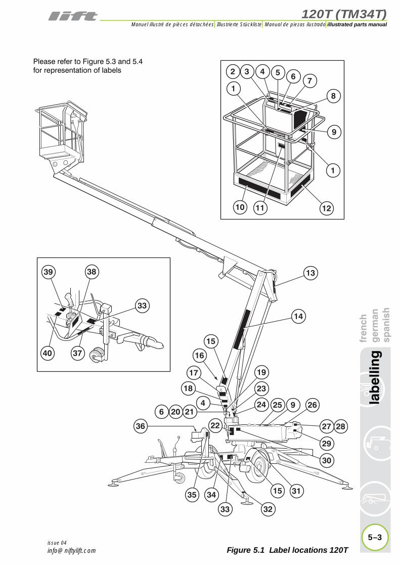
5.1 Label locations 120TItem Description Part Number
1 Harness point P14883
french P14883
german P14883
spanish P14883
dutch P14883
italian P14883
2 Button box (without cage weigh) Bi-energyAC or DC
P15924P15925
french P15924P15925
german P15924P15925
spanish P15924P15925
dutch P15924P15925
italian P15924P15925
3 Button box (with cage weigh) Bi-energyAC or DC
P17457P17212
french P17457P17212
german P17457P17212
spanish P17457P17212
dutch P17457P17212
italian P17457P17212
4 If emergency stop disabled P14864
french P14865
german P14866
spanish P14867
dutch P16628
italian P16651
5 Basket levelling P10853
french P10853
german P10853
spanish P10853
dutch P10853
italian P10853
120T (TM34T)
fren
chg
erm
ansp
anis
hla
bel
ling
5–3
illustrated parts manualManuel illustré de pièces détachées Illustrierte Stückliste Manual de piezas ilustrado
issue 04
3 4
15
39
17
25 9 26
29
27 28
35 34
40 37
33
31
30
24
23
19
33
38
32
15
18
4
22
206
2
1
11
657
10
8
13
14
9
1
12
36
16
21
Please refer to Figure 5.3 and 5.4for representation of labels
Figure 5.1 Label locations 120T

120T (TM34T)
5–4
lab
ellin
gfr
ench
ger
man
span
ish
illustrated parts manual Manuel illustré de pièces détachées Illustrierte Stückliste Manual de piezas ilustrado
issue 04
5.1 continuedItem Description Part Number
6 Outrigger alarm P18842
french P18843
german P18844
spanish P18845
dutch P18846
italian P18847
7 Push and release P19092
french P19092
german P19092
spanish P19092
dutch P19092
italian P19092
8 Control levers - Cage P14927
french P14927
german P14927
spanish P14927
dutch P14927
italian P14927
9 General warning P21970
french P21971
german P21972
spanish P21973
dutch P21974
italian P21975
10 niftylift.com P14597
french P14597
german P14597
spanish P14597
dutch P14597
italian P14597
11 Operating instructions P14892
french P14892
german P14892
spanish P14892
dutch P14892
italian P14892

120T (TM34T)
fren
chg
erm
ansp
anis
hla
bel
ling
5–5
illustrated parts manualManuel illustré de pièces détachées Illustrierte Stückliste Manual de piezas ilustrado
issue 04
Figure 5.1 Label locations 120T
3 4
15
39
17
25 9 26
29
27 28
35 34
40 37
33
31
30
24
23
19
33
38
32
15
18
4
22
206
2
1
11
657
10
8
13
14
9
1
12
36
16
21
Please refer to Figure 5.3 and 5.4for representation of labels

120T (TM34T)
5–6
lab
ellin
gfr
ench
ger
man
span
ish
illustrated parts manual Manuel illustré de pièces détachées Illustrierte Stückliste Manual de piezas ilustrado
issue 04
5.1 continuedItem Description Part Number
12 Warning - SWL 200kg P14801
french P14801
german P14801
spanish P14801
dutch P14801
italian P14801
13 Coupling instructions P14896
french P14897
german P14898
spanish P14899
dutch P16263
italian P17267
14 Nifty 120T P14598
french P14598
german P14598
spanish P14598
dutch P14598
italian P14598
15 Crush hazard P14782
french P14782
german P14782
spanish P14782
dutch P14782
italian P14782
16 Head protection P14921
french P14921
german P14921
spanish P14921
dutch P14921
italian P14921
17 Component stability P19708
french P19709
german P19710
spanish P19711
dutch P19712
italian P19713

120T (TM34T)
fren
chg
erm
ansp
anis
hla
bel
ling
5–7
illustrated parts manualManuel illustré de pièces détachées Illustrierte Stückliste Manual de piezas ilustrado
issue 04
Figure 5.1 Label locations 120T
3 4
15
39
17
25 9 26
29
27 28
35 34
40 37
33
31
30
24
23
19
33
38
32
15
18
4
22
206
2
1
11
657
10
8
13
14
9
1
12
36
16
21
Please refer to Figure 5.3 and 5.4for representation of labels
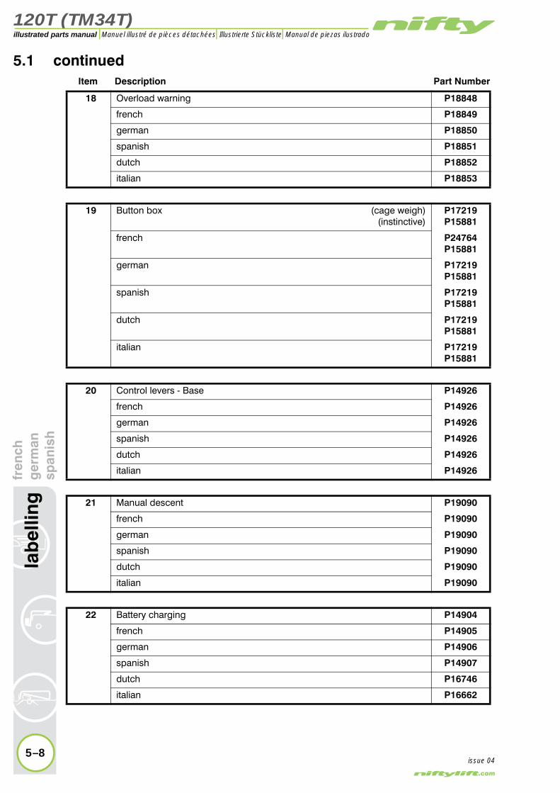
120T (TM34T)
5–8
lab
ellin
gfr
ench
ger
man
span
ish
illustrated parts manual Manuel illustré de pièces détachées Illustrierte Stückliste Manual de piezas ilustrado
issue 04
5.1 continuedItem Description Part Number
18 Overload warning P18848
french P18849
german P18850
spanish P18851
dutch P18852
italian P18853
19 Button box (cage weigh)(instinctive)
P17219P15881
french P24764P15881
german P17219P15881
spanish P17219P15881
dutch P17219P15881
italian P17219P15881
20 Control levers - Base P14926
french P14926
german P14926
spanish P14926
dutch P14926
italian P14926
21 Manual descent P19090
french P19090
german P19090
spanish P19090
dutch P19090
italian P19090
22 Battery charging P14904
french P14905
german P14906
spanish P14907
dutch P16746
italian P16662

120T (TM34T)
fren
chg
erm
ansp
anis
hla
bel
ling
5–9
illustrated parts manualManuel illustré de pièces détachées Illustrierte Stückliste Manual de piezas ilustrado
issue 04
Figure 5.1 Label locations 120T
3 4
15
39
17
25 9 26
29
27 28
35 34
40 37
33
31
30
24
23
19
33
38
32
15
18
4
22
206
2
1
11
657
10
8
13
14
9
1
12
36
16
21
Please refer to Figure 5.3 and 5.4for representation of labels
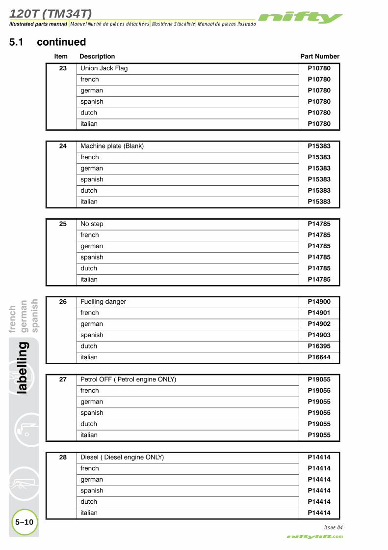
120T (TM34T)
5–10
lab
ellin
gfr
ench
ger
man
span
ish
illustrated parts manual Manuel illustré de pièces détachées Illustrierte Stückliste Manual de piezas ilustrado
issue 04
5.1 continuedItem Description Part Number
23 Union Jack Flag P10780
french P10780
german P10780
spanish P10780
dutch P10780
italian P10780
24 Machine plate (Blank) P15383
french P15383
german P15383
spanish P15383
dutch P15383
italian P15383
25 No step P14785
french P14785
german P14785
spanish P14785
dutch P14785
italian P14785
26 Fuelling danger P14900
french P14901
german P14902
spanish P14903
dutch P16395
italian P16644
27 Petrol OFF ( Petrol engine ONLY) P19055
french P19055
german P19055
spanish P19055
dutch P19055
italian P19055
28 Diesel ( Diesel engine ONLY) P14414
french P14414
german P14414
spanish P14414
dutch P14414
italian P14414

120T (TM34T)
fren
chg
erm
ansp
anis
hla
bel
ling
5–11
illustrated parts manualManuel illustré de pièces détachées Illustrierte Stückliste Manual de piezas ilustrado
issue 04
Figure 5.1 Label locations 120T
3 4
15
39
17
25 9 26
29
27 28
35 34
40 37
33
31
30
24
23
19
33
38
32
15
18
4
22
206
2
1
11
657
10
8
13
14
9
1
12
36
16
21
Please refer to Figure 5.3 and 5.4for representation of labels

120T (TM34T)
5–12
lab
ellin
gfr
ench
ger
man
span
ish
illustrated parts manual Manuel illustré de pièces détachées Illustrierte Stückliste Manual de piezas ilustrado
issue 04
5.1 continuedItem Description Part Number
29 Noise warning - 85 dB P17124
french P17124
german P17124
spanish P17124
dutch P17124
italian P17124
30 Battery - Isolator P18600
french P18600
german P18600
spanish P18600
dutch P18600
italian P18600
31 Tyre pressure - 65 psi P14876
french P14876
german P14876
spanish P14876
dutch P14876
italian P14876
32 Point load - 9.4 kN P14962
french P14962
german P14962
spanish P14962
dutch P14962
italian P14962
33 Trailer towing (Not fitted to Traction Drive or Fixed Axle Models) P17341
french P17341
german P17341
spanish P17341
dutch P17341
italian P17341
34 Outriggers P14841
french P14842
german P14843
spanish P14844
dutch P16262
italian P16636

120T (TM34T)
fren
chg
erm
ansp
anis
hla
bel
ling
5–13
illustrated parts manualManuel illustré de pièces détachées Illustrierte Stückliste Manual de piezas ilustrado
issue 04
Figure 5.1 Label locations 120T
3 4
15
39
17
25 9 26
29
27 28
35 34
40 37
33
31
30
24
23
19
33
38
32
15
18
4
22
206
2
1
11
657
10
8
13
14
9
1
12
36
16
21
Please refer to Figure 5.3 and 5.4for representation of labels
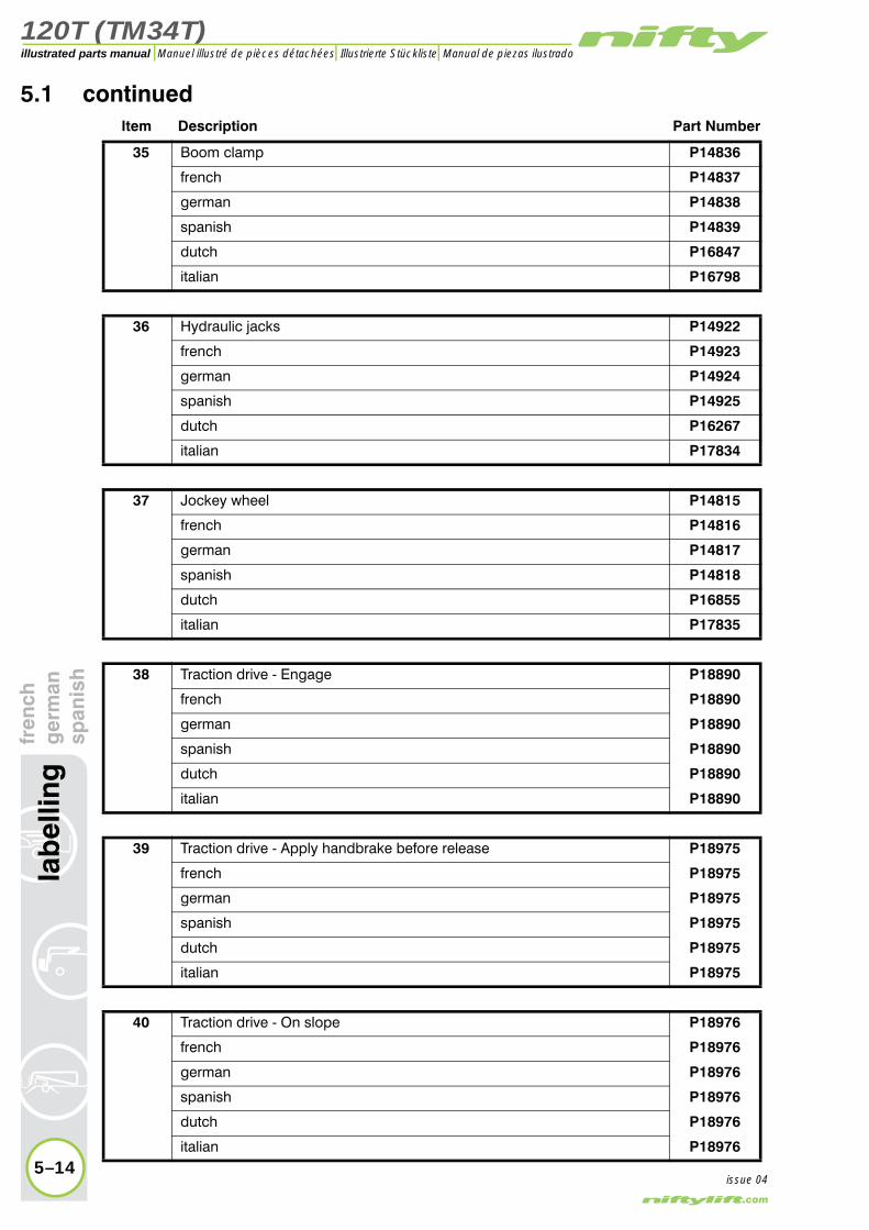
120T (TM34T)
5–14
lab
ellin
gfr
ench
ger
man
span
ish
illustrated parts manual Manuel illustré de pièces détachées Illustrierte Stückliste Manual de piezas ilustrado
issue 04
5.1 continuedItem Description Part Number
35 Boom clamp P14836
french P14837
german P14838
spanish P14839
dutch P16847
italian P16798
36 Hydraulic jacks P14922
french P14923
german P14924
spanish P14925
dutch P16267
italian P17834
37 Jockey wheel P14815
french P14816
german P14817
spanish P14818
dutch P16855
italian P17835
38 Traction drive - Engage P18890
french P18890
german P18890
spanish P18890
dutch P18890
italian P18890
39 Traction drive - Apply handbrake before release P18975
french P18975
german P18975
spanish P18975
dutch P18975
italian P18975
40 Traction drive - On slope P18976
french P18976
german P18976
spanish P18976
dutch P18976
italian P18976

120T (TM34T)
fren
chg
erm
ansp
anis
hla
bel
ling
5–15
illustrated parts manualManuel illustré de pièces détachées Illustrierte Stückliste Manual de piezas ilustrado
issue 04
Figure 5.1 Label locations 120T
3 4
15
39
17
25 9 26
29
27 28
35 34
40 37
33
31
30
24
23
19
33
38
32
15
18
4
22
206
2
1
11
657
10
8
13
14
9
1
12
36
16
21
Please refer to Figure 5.3 and 5.4for representation of labels

120T (TM34T)
5–16
lab
ellin
gfr
ench
ger
man
span
ish
illustrated parts manual Manuel illustré de pièces détachées Illustrierte Stückliste Manual de piezas ilustrado
issue 04
5.2 Label locations TM34TItem Description Part Number
1 Harness point P14883
2 Button box (without cage weigh) Bi-energyAC or DC
P15924P15925
3 Button box (with cage weigh) Bi-energyAC or DC
P17457P17212
4 If emergency stop disabled P14864
5 Basket levelling P10853
6 Outrigger alarm P18842
8 Control levers - Cage P14927
9 General warning P21970
10 niftylift.com P14597
11 Operating instructions P14892
13 Coupling instructions P14896
15 Crush hazard P14782
16 Head protection P14921
17 Component stability P19708
19 Button box (cage weigh)(instinctive)
P17219P15881
20 Control levers - Base P14926
21 Manual descent P19090
22 Battery charging P14904
24 Machine plate (Blank) P15383
25 No step P14785
27 Petrol OFF ( Petrol engine ONLY) P19055
30 Battery - Isolator P18600
31 Tyre pressure - 65 psi P14876
32 Point load - 9.4 kN P14962
33 Trailer towing (Not fitted to Traction Drive or Fixed Axle Models) P17341
34 Outriggers P14841
35 Boom clamp P14836
36 Hydraulic jacks P14922
37 Jockey wheel P14815
38 Traction drive - Engage P18890
39 Traction drive - Apply handbrake before release P18975
40 Traction drive - On slope P18976
41 * Cage gate warning P18432
42 * Footswitch P14884
43 * SWL - 500 lbs P17328
44 * Nifty TM34T (Grey) P14612
45 * Rotating machinery P15010
46 * Carb. Regulations P15334
47 * Noise warning - 73 dB P17123
48 * Daily safety check list P14908
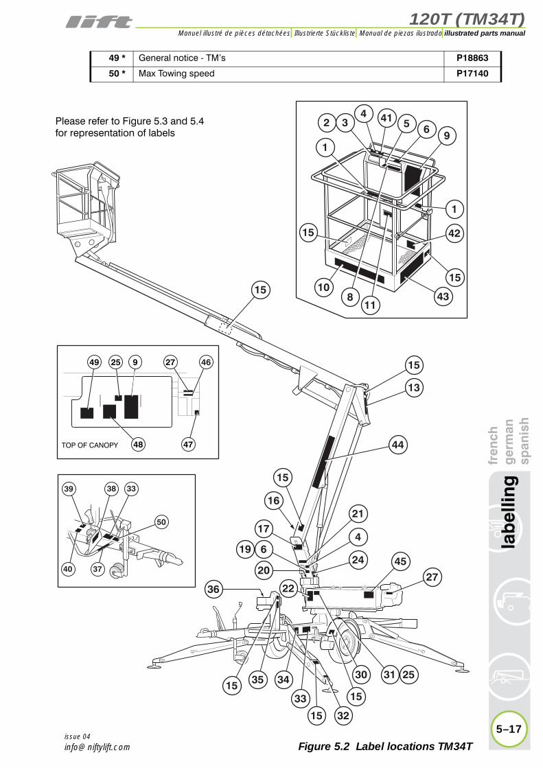
120T (TM34T)
fren
chg
erm
ansp
anis
hla
bel
ling
5–17
illustrated parts manualManuel illustré de pièces détachées Illustrierte Stückliste Manual de piezas ilustrado
issue 04
Figure 5.2 Label locations TM34T
432
15
41 5 69
1
42
43
15
1
810
11
15
17
4527
3515 34
33
15
30
15
31 25
4
21
24
32
619
22
15
13
15
44
36
16
925
4748
27 46
TOP OF CANOPY
39
40 37
50
38 33
49
20
Please refer to Figure 5.3 and 5.4for representation of labels
49 * General notice - TM’s P18863
50 * Max Towing speed P17140
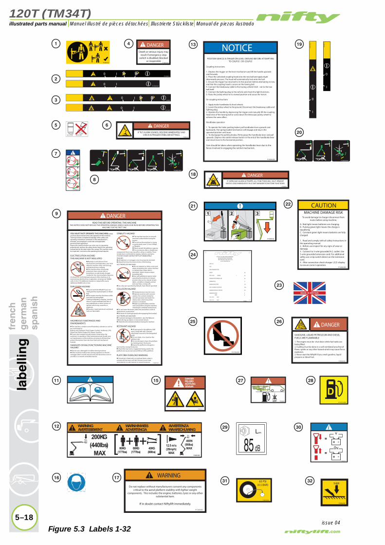
120T (TM34T)
5–18
lab
ellin
gfr
ench
ger
man
span
ish
illustrated parts manual Manuel illustré de pièces détachées Illustrierte Stückliste Manual de piezas ilustrado
issue 04
POSITION VEHICLE & TRAILER ON LEVEL GROUND BEFORE ATTEMPTING TO COUPLE / DE-COUPLE
Coupling instructions
1. Depress the trigger on the lever mechanism and lift the handle upwards and forwards.2. Place the unlocked coupling head onto the tow ball and apply slight downwards pressure. The head will automatically lock onto the ball.3. Ensure the trigger has returned to its free position before attempting to tow, and that the coupling head is secure on the towing ball.4. Connect the breakaway cable to the towing vehicle hitch - not to the tow ball itself. 5. Connect the lighting plug to the vehicle and check the light functions.6. Raise the jockey wheel to its stowed position and secure for transit.
De-coupling instructions
1. Apply trailer handbrake & chock wheels.2. Lower the jockey wheel to the ground. Disconnect the breakaway cable and lighting plug.3. Operate the handle by depressing the trigger and manually lift the coupling head clear of the towing ball or screw down the telescopic jockey wheel to achieve the same effect.
Handbrake operation
1. To operate the trailer parking brakes pull handbrake lever upwards and backwards. The spring loaded mechanism will engage and stay in the operated position until reset.2. To disengage the parking brakes, firmly grasp the handbrake lever and pull upwards. Depress the ratchet release button in the end of the handbrake lever and return lever to the horizontal position.
Care should be taken when operating the handbrake lever due to the forces involved in engaging the ratchet mechanism.
NOTICE
P14896/001
P14785/001
e-mail: [email protected]
HYD. CCT D ISSUE
ELEC. CCT D ISSUE
Deg.MAX. ALLOWABLE INCLINATION
P10805/5
+
A
V
bar
m/s
N
kg
kg
kg
AMPS
MAXIMUM VOLTAGE
MAXIMUM HYDRAULIC PRESSURE
MAXIMUM WIND SPEED
MAXIMUM PULL
MAXIMUM SAFE WORKING LOAD
RATED LOAD PERSONS
WEIGHT
YEAR OF MANUFACTURE
TYPE
SERIAL No
TEL 01908 223456 : FAX 01908 312733 MILTON KEYNES MK13 0ER ENGLAND
NIFTYLIFT LTD.,FINGLE DRIVE,STONEBRIDGE
65 PSI(4.5 BAR)
P14876/001
MADE IN BRITAIN
P14927/001
P14921/001
MACHINE DAMAGE RISKTo avoid damage to charger disconnect from
mains before using machine.
A. Red light means batteries are charging.B. Pulsing green light means the charge is equalising.C. Constant green light means batteries are fully charged.
1. Read and comply with all safety instructions in the operating manual.2. Before use inspect for any signs of wear or damage.3. Connect to 3-wire grounded A.C. outlet. Use 3-wire grounded extension cord. For additional safety use a trip switch device on the extension cord.4. After connection check charger L.E.D. display to ensure correct operation.
CAUTION
P14904/001
GASOLINE, LIQUID PETROLEUM AND DIESEL FUELS ARE FLAMMABLE
1. The engine must be shut down while fuel tanks are being filled.2. Fuelling must be done in a well ventilated area free of flame, sparks or any other hazard which may cause fire or explosion.3. Never start the Niftylift if you smell gasoline, liquid propane or diesel fuel.
DANGER
P14900/001
P14414/001
P14926/001
9.4kN
P14962/001
0 IP17212/01
0 IP17457/01
P15925/0010 I
P15924/010 I
P15881/01
0
I
WARNING
P17203/001
Do not replace without manufacturers consent any components critical to the aerial platform stability with lighter weight
components. This includes the engine, batteries, tyres or any other substantial item.
If in doubt contact Niftylift immediately.
DANGERDeath or serious injury may
result if emergency stop switch is disabled, blocked
or inoperableP14864/001
P17219/001
0
I
LWA
85 dB
P1478 /0
DANGERPELIGROACHTUNGGEVAAR
P14892/02
READ THIS BEFORE OPERATING THIS MACHINETHIS NOTICE DOES NOT REPLACE THE OPERATING MANUAL WHICH SHOULD BE READ BEFORE OPERATING THIS
MACHINE FOR THE FIRST TIME
YOU MUST NOT OPERATE THIS MACHINE unless you have been trained in the safe operation of this machine. Training includes complete knowledge of the safety and operating instructions contained in the manufacturer's manuals, your employer's work rules and applicable governmental regulations.Inspect the machine before use to be sure it is operating properly and perform the safety checks listed in the operating manual and on the label under this canopy. This machine must be inspected / serviced as the operating manual requires.
ELECTROCUTION HAZARD THIS MACHINE IS NOT INSULATED
� Maintain a safe distance from electrical lines and apparatus, you must allow for machine sway, rock and sag and electrical lines swaying.� This machine does not provide protection from contact with or proximity to an electrically charged conductor. You must maintain clearance
of at least 3m (10 ft) between any part of the machine or its load and any electrical line or apparatus carrying over 50,000 volts. 0.3m (1 ft) additional clearance is required for every additional 30,000 volts or less.
EXPLOSION HAZARD� Do not start the Niftylift if you can smell gasoline, liquid propane or diesel fuel.� The engine must be shut down while fuel tanks are being filled.Fuelling and battery charging must be done in a well ventilated area free of any naked flame or other sources of ignition which may cause fire or explosion.� Gasoline, liquid petroleum and diesel fuels are flammable.
HAZARDOUS SUBSTANCES AND ENVIRONMENTS� This machine contains several hazardous substances such as but not limited to:Battery acid, Hydraulic Fluid, Engine Coolant, Antifreeze, LPG, Diesel Fuel, Petrol, Engine Oil, Grease, Gasoline.� Covers and canopies should remain closed when the machine is in operation. Only trained personnel should carry out maintenance on the machine, ensuring at all times they protect themselves from electrical, heat and mechanical hazards.
DAMAGED OR MALFUNCTIONING MACHINE HAZARD� Do not use a damaged or malfunctioning machine.� If the machine malfunctions during operation or the tilt / outrigger alarm sounds stop all work and descend as soon as possible in a smooth controlled manner.
STABILITY HAZARD� The machine must be on smooth firm level surface before using the booms.� Do not use the machine in strong or gusty winds (over 12.5m/s (45kph or 28mph)).� Never exceed the platform capacity.� Do not remove, alter or disable any
components that in any way affect safety or stability. These include but is not limited to engines, batteries and tyres. IF IN ANY DOUBT CONTACT NIFTYLIFT IMMEDIATELY.TRAILERS:� All stabilisers or outriggers must be properly extended.� All jack feet must be lowered onto a firm footing.
SELF PROPELLED MACHINES:� Do not attempt to climb or descend slopes exceeding 25%, unless machine is 4 wheel drive, where 30% is permitted. Never traverse slopes exceeding 20%.� Use with additional caution when operating the machine (in stowed position only) across uneven terrain, debris, unstable or slippery surface and near holes or drop-offs.
� Use only tyres specified by Niftylift, foam filled if specified.
COLLISION HAZARD� Head protection must be worn.� Operate machine with extreme caution. Use controls slowly for smooth operation and watch for obstructions which may strike persons or machine.� Make yourself familiar with the work area before using the machine, checking for overhead obstructions.
� Do not lower the boom unless the area below is free of obstructions or personnel.� Be aware of crushing hazards when gripping the handrail.
SELF PROPELLED MACHINES:� To prevent damage to the platform, raise the flyboom before driving up slopes or over uneven terrain.� Check the drive direction before moving the machine.
RESTRAINT HAZARD� All personnel in the platform shall wear a body belt with a lanyard attachment secured to the designated point.� Do not climb, sit or stand on the platform rails.� Do not attempt to leave the platform by climbing down the booms.� Ensure the platform entry gate is
down before raising the booms.� Check that any tools or equipment being used in the platform are secure and cannot fall out of the platform.
PLATFORM OVERLOAD WARNING� If machine is fitted with an overload alarm, when it activates all functions will halt. Remove excess load immediately in a safe manner to restore functions. P18672/01
DANGER
P14801/003
80KG(177lbs)
80KG(177lbs)
40KG(88lbs)
WARNINGAVERTISSEMENT
WARNHINWEISADVERTENCIA
AVVERTENZAWAARSCHUWING
(440lbs)200KG
MAX12.5 m/s(28mph)
MAX
400N(90lbs)MAX
DANGER
P18842/02
IF TILT ALARM SOUNDS, DESCEND IMMEDIATELY AND CHECK OUTRIGGER/STABILISER SETTINGS.
DANGER
P18848/01
IF OVERLOAD ALARM ACTIVATES, ALL FUNCTIONS WILL HALT. REMOVE EXCESS LOAD IMMEDIATELY IN A SAFE MANNER TO RESTORE FUNCTIONS.
P18600/01
+ -
+ -
P19092/01
1.
2.
3.
P19055/01
P14883/02
P19090/02
1 4
11 15
16 17
2
3
5
7
8
6
9
12
13
18
21 22
20
24
25
27
29 30
31 32
28
23
19
26
Figure 5.3 Labels 1-32

120T (TM34T)
fren
chg
erm
ansp
anis
hla
bel
ling
5–19
illustrated parts manualManuel illustré de pièces détachées Illustrierte Stückliste Manual de piezas ilustrado
issue 04
Figure 5.4 Labels 33-50
WARNINGSerious injury may result if all four outriggers / stabilisers are not lowered onto a firm level surface and machine base made level ensuring each supporting foot is taking equal weight with the wheels clear of the ground.
P14841/001
1 2 3 4
1
2 4
3
TO PREVENT UNNECESSARY LOADING ON THE MACHINE USE THE FOLLOWING STABILISER SEQUENCE:1. DEPLOY FRONT STABILISERS (3&4) FIRST, UNTIL CONTACT IS MADE WITH THE GROUND.2. NEXT DEPLOY REAR STABILISERS (1&2), UNTIL CONTACT IS MADE WITH THE GROUND.3. FINALLY LEVEL MACHINE BASE, USING THE FRONT THEN REAR STABILISERS.4. RAISE STABILISERS USING THE REVERSE SEQUENCE.
STABILISER IDENTIFICATION
PUSH DOWN AND HOLD LEVER TO ACTIVATE STABILISER CONTROLS CONTROL LEVERS
P14922/001
NOTICE
MACHINE DAMAGE RISK
BOOM TRAVELLING CLAMP
1) Release before operating machine.2) Engage before towing machine.
P14836/001
CAUTION
Serious injury may result if jockey wheel clamp is released, unless hitch is supported by vehicle or front jacks. Keep hands clear of jockey wheel handle when releasing the jockey wheel clamp.
P14815/001
WARNING
BEFORE USERefer to the operating manual or the label located inside the canopy and perform the daily maintenance / check routine as required. Read all WARNING, DANGER, CAUTION and NOTICE labels on the machine.
ACTIVATING THE MACHINE1. Ensure all red Emergency Stops are out.2. Turn key switch at the ground control station to activate the ground or platform controls.3. If no other power option is already running, the 'Instinctive' control circuit will default to battery power.(If applicable)4. To start the engine turn the selector to the start ( ) position, the engine will fire. When running, the control circuit will adapt to the engine pump.5. Cold diesel engines: Push and hold the glow button ( ) for 10 seconds then turn the selector to the start position and the engine will fire.6. If the engine is stopped, the control circuit will revert back to the battery power.
EMERGENCY STOP Pushing in an emergency stop will stop all functions and turn the engine off.
EMERGENCY HANDPUMPIn the event that the controls fail or the operator becomes incapacitated the booms can be operated by using the handpump adjacent to the ground controls. To swing the booms fit 1/2 inch drive socket to the end of swing worm gear and crank round manually.
LOW BATTERY WARNING (Battery models)
If the siren sounds and operations become intermittent, the batteries need charging. Switch to engine power or charge the machine immediately.
TO OPERATE OUTRIGGERS1. Position the Niftylift on firm, level ground, never work with base across or adjacent to any slope.2. Position the Niftylift, bearing in mind range of boom movement so that any overhead obstruction or possible hazards such as, but not limited to: power cables, telephone lines, drains, manhole covers etc.3. If the load bearing capacity of the ground is in any doubt the machine must not be used.4. Apply handbrake, chock wheels and cordon off area using appropriate cones, barriers and flags.5. Release boom travelling clamp.6. Check all red emergency stops are not engaged i.e. fully out.7. To deploy the outriggers refer to the decals at the outrigger control station (hydraulic) or beside the outriggers (manual).ALWAYS LOWER BOOMS FULLY BEFORE ADJUSTING, RAISING, RETRACTING OR MOVING THE OUTRIGGERS IN ANY WAY.
TO OPERATE BOOMS To operate from ground or platform:1. Press and hold the green power button or footswitch.2. Slowly move the desired control according to the markings on the control panel.
AFTER USEReturn the machine to the stowed position. Turn the key to the 'off' position.Remove key. Chock wheels.
READ THIS BEFORE OPERATING THIS MACHINETHIS NOTICE DOES NOT REPLACE THE OPERATING MANUAL WHICH SHOULD BE READ BEFORE OPERATING
THIS MACHINE FOR THE FIRST TIME
P14888/02
NOTICE
33
34
35
36
37
38
39
40
41* 42*
45**
43*
44
46*
47*
48*
50*
49*
*TM34T (USA) ONLY
2.1.
3.
P17341/02
DANGERHANDBRAKE MUST BE FULLYAPPLIED BEFORE TRACTION
SYSTEM IS DIS-ENGAGED FROM ROAD WHEELS.
RELEASE HANDBRAKE BEFORE DRIVING OR TOWING.
P16536/001
DANGERTRACTION DRIVE IS FOR USE ON FLAT LEVEL
GROUND ONLY.USE OF TRACTION DRIVE ON SLOPES GREATER THAN 10% MAY RESULT IN
SERIOUS INJURY.
P16541/001 P17140/002
MAX45mph72kph
P18432/01
LWA
73 dB
Death or serious injury may result if footswitch is disabled,
blocked or inoperable.?
DANGER
POWER ON
POWER OFF
P14884/001
P15334/01
ENGINE CONFORMS TO EMISSIONCERTIFICATION : EPA PHASE -2 / CARB TIER-2
REFER TO HONDA DOCUMENT PWL 50975A (9603) FOR DETAILSOR CONSULT MANUFACTURERS HANDBOOK
DAILY SAFETY CHECK LIST1. Check operating and safety manuals are legible and located in their box within the platform (if applicable).2. Check safety belts and hats.3. Check all decals and placards to see if in place and legible.4. Check platform is securely fastened to platform support.5. Check wheels and tyres.6. Check outriggers / stabilisers (if applicable) for condition, micro switch operation and security.7. Check batteries for condition, cleanliness, connectors and electrolyte levels. 8. Check engine oil and coolant levels (if applicable).9. Check Installation of all guards, covers and boom clamps.10. Check for loose, missing or damaged parts.11. Check all hydraulic hoses and electrical cables and wiring.12. Check hydraulic, fuel and air systems for leaks.13. Do not exceed rated platform capacity.14. Check foot pedal for proper operation (if applicable).15. Check all operating and emergency controls - select an area free from obstructions and hazards. Exercise extreme caution throughout the checking procedure especially when checking brakes.16. Check operation of emergency handpump.17. Check all brakes and lights.18. Check tilt sensor / alarm horn and beacons.19. Check high engine and / or high drive limit switches.20. Check and refer to operating and workshop manual for further daily / periodic checks and inspections.
DO NOT OPERATE A MALFUNCTIONING MACHINEP14908/001
NOTICE
DANGERROTATING AND ELECTRICAL MACHINE
HAZARD-KEEP CLEAR-
AVOID CONTACT - KEEP A SAFE DISTANCE AWAY OR DEATH OR SERIOUS
INJURY MAY RESULT.?P15010/001
P17328/001
80KG(177lbs)
80KG(177lbs)
65KG(144lbs)
WARNINGAVERTISSEMENT
WARNHINWEISADVERTENCIA
AVVERTENZAWAARSCHUWING
(500lbs)225KG
MAX12.5 m/s(28mph)
MAX
400N(90lbs)MAX
P18890/01

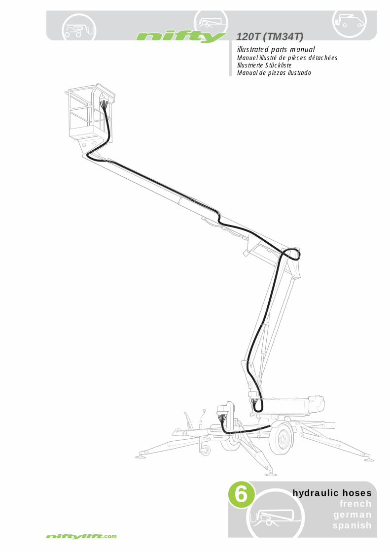
120T (TM34T)
6
illustrated parts manualManuel illustré de pièces détachéesIllustrierte StücklisteManual de piezas ilustrado
hydraulic hosesfrench
germanspanish

120T (TM34T)illustrated parts manual Manuel illustré de pièces détachées Illustrierte Stückliste Manual de piezas ilustrado
hyd
raul
ic h
ose
sfr
ench
ger
man
span
ish
6.1 Hose kit 120T (TM34T)Number Description
1Base control to RAM 1 - pressure
2Base control to RAM 1 - pilot
3Cage control to RAM 1 - pressure
4Cage control to RAM 1 - pilot
5Base control to RAM 2 - pressure
6Base control to RAM 2 - pilot
7Cage control to RAM 2 - pressure
8Cage control to RAM 2 - pilot
9Base control to slew- pressure
10Base control to slew- pilot
11Cage control to slew- pressure
12Cage control to slew- pilot
13Cage control to telescoping ram - pressure
14Cage control to telescoping ram - pilot
15Cage control to levelling ram (slave)- pressure
16Cage control to levelling ram (slave)- pilot
17Cage control to levelling ram (master)- pressure
18Cage control to levelling ram (master)- pilot
19Base control toCage control - pressure
20Manual select (A) to Leg V-block - pressure
6–2issue 07
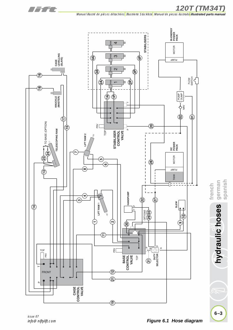
120T (TM34T)
fren
chg
erm
ansp
anis
hh
ydra
ulic
ho
ses
6–3
illustrated parts manualManuel illustré de pièces détachées Illustrierte Stückliste Manual de piezas ilustrado
issue 07
Figure 6.1 Hose diagram
B A
P
P
LIF
T R
AM
1
LIF
T R
AM
2
KN
UC
KLE
(MA
STE
R)
CA
GE
LEV
ELL
ING
(SLA
VE
)
TO B
AS
E (
OP
TIO
N)
T P
TOP
TOP
PR
V
P
T
TELE
SC
OP
ING
RA
M
12
34
RA
MR
AM
RA
MR
AM
DC
PO
WE
RP
AC
KM
OTO
R
PUMP
BI-
EN
ER
GY
PO
WE
RP
AC
KM
OTO
R
PUMP
PR
V
TOP
T
FRONT
HA
ND
PU
MP
PR
V P
SLE
W
DU
TYS
ELE
CTO
R
TAN
K
CA
GE
CO
NTR
OL
VALV
E
BA
SE
CO
NTR
OL
VALV
E
STA
BIL
ISE
RC
ON
TRO
LV
ALV
E
}
STA
BIL
ISE
RS
PU
MP
DU
MP
FLO
WS
WIT
CH
OP
TIO
NS
NR
V
19
1816
21
11
1
3
14
1323
24
1715
48
56
7
212
910
30
2903
22 2728
20
0102
2A 2P
1A 1P
3A 3P
4A 4P
31

120T (TM34T)illustrated parts manual Manuel illustré de pièces détachées Illustrierte Stückliste Manual de piezas ilustrado
hyd
raul
ic h
ose
sfr
ench
ger
man
span
ish
6.1 continued
Number Description
21Base control toCage control - pilot
22Base block to tank - return
23Base control to telescoping ram - pressure (OPTION)
24Base control to telescoping ram - pilot(OPTION)
27Power pack to manual select- pressure
28Jack control to tank - return
29Duty selector to handpump (OPTION)
30Base control tohandpump - return
31Manual select (B) to base control - pressure
1A Leg 1 - pressure
1P Leg 1 - pilot
2A Leg 2 - pressure
2P Leg 2 - pilot
3A Leg 3 - pressure
3P Leg 3 - pilot
4A Leg 4 - pressure
4P Leg 4 - pilot
01Bi-energy return(OPTION)
02Power pack -pressure (OPTION)
03Hand pump to HPfilter (OPTION)
6–4issue 07

120T (TM34T)
fren
chg
erm
ansp
anis
hh
ydra
ulic
ho
ses
6–5
illustrated parts manualManuel illustré de pièces détachées Illustrierte Stückliste Manual de piezas ilustrado
issue 07
Figure 6.1 Hose diagram
B A
P
P
LIF
T R
AM
1
LIF
T R
AM
2
KN
UC
KLE
(MA
STE
R)
CA
GE
LEV
ELL
ING
(SLA
VE
)
TO B
AS
E (
OP
TIO
N)
T P
TOP
TOP
PR
V
P
T
TELE
SC
OP
ING
RA
M
12
34
RA
MR
AM
RA
MR
AM
DC
PO
WE
RP
AC
KM
OTO
R
PUMP
BI-
EN
ER
GY
PO
WE
RP
AC
KM
OTO
R
PUMP
PR
V
TOP
T
FRONT
HA
ND
PU
MP
PR
V P
SLE
W
DU
TYS
ELE
CTO
R
TAN
K
CA
GE
CO
NTR
OL
VALV
E
BA
SE
CO
NTR
OL
VALV
E
STA
BIL
ISE
RC
ON
TRO
LV
ALV
E
}
STA
BIL
ISE
RS
PU
MP
DU
MP
FLO
WS
WIT
CH
OP
TIO
NS
NR
V
19
1816
21
11
1
3
14
1323
24
1715
48
56
7
212
910
30
2903
22 2728
20
0102
2A 2P
1A 1P
3A 3P
4A 4P
31

120T (TM34T)illustrated parts manual Manuel illustré de pièces détachées Illustrierte Stückliste Manual de piezas ilustrado
h an ish
6.2 Traction Drive Kit (P14205)Number Description french german spanish
01Cage V-block toTraction V-block - pressure
02Traction V-block toLeg V-block - return
03PRV to leg V-block - return
04Traction V-block to PRV - pressure
05PRV to check valve - pressure
06Check valve toTraction V-block - return
07ATraction V-block toRH motor - pressure
07PTraction V-block toRH motor - pilot
08ATraction V-block toLH motor - pressure
08PTraction V-block toLH motor - pilot
09 Check valve to RAM
10 Check valve to RAM
6–6
hyd
raul
ic h
ose
sfr
enc
ger
msp
an
issue 07