1203-5.5, Bulletin 1203 Serial Communnications … 1203 Serial Communications Module (Series B) ......
73
User Manual Bulletin 1203 Serial Communications Module (Series B) RS232/422/483 (Using DF1 Protocol) DH485 (Cat. No. 1203–GD2, –GK2, –GM2) Allen-Bradley efesotomasyon.com - Allen Bradley,Rockwell,plc,servo,drive
Transcript of 1203-5.5, Bulletin 1203 Serial Communnications … 1203 Serial Communications Module (Series B) ......

UserManual
Bulletin 1203Serial CommunicationsModule(Series B)
RS232/422/483 (Using DF1 Protocol)
DH485
(Cat. No. 1203–GD2, –GK2, –GM2)
Allen-Bradley
efesotomasyon.com - Allen Bradley,Rockwell,plc,servo,drive

Solid state equipment has operational characteristics differing fromthose of electromechanical equipment. “Safety Guidelines for theApplication, Installation and Maintenance of Solid State Controls”(Publication SGI-1.1) describes some important differences betweensolid state equipment and hard–wired electromechanical devices.Because of this difference, and also because of the wide variety ofuses for solid state equipment, all persons responsible for applyingthis equipment must satisfy themselves that each intendedapplication of this equipment is acceptable.
In no event will the Allen-Bradley Company be responsible or liablefor indirect or consequential damages resulting from the use orapplication of this equipment.
The examples and diagrams in this manual are included solely forillustrative purposes. Because of the many variables andrequirements associated with any particular installation, theAllen-Bradley Company cannot assume responsibility or liability foractual use based on the examples and diagrams.
No patent liability is assumed by Allen-Bradley Company withrespect to use of information, circuits, equipment, or softwaredescribed in this manual.
Reproduction of the contents of this manual, in whole or in part,without written permission of the Allen-Bradley Company isprohibited.
Throughout this manual we use notes to make you aware of safetyconsiderations.
!ATTENTION: Identifies information about practicesor circumstances that can lead to personal injury ordeath, property damage, or economic loss.
Attentions help you:
• identify a hazard
• avoid the hazard
• recognize the consequences
Important: Identifies information that is especially important forsuccessful application and understanding of the product.
PLC, PLC–2, PLC–3, PLC–5, SLC, SLC 500, PanelView, RediPANEL, Data Highway Plus, and Dataliner are trademarks ofAllen-Bradley Company, Inc.IBM is a registered trademark of International Business Machines, Incorporated.
Important User Information
efesotomasyon.com - Allen Bradley,Rockwell,plc,servo,drive

Who Should Use this Manual P–1. . . . . . . . . . . . . . . . . . . . . . . . . . . . Purpose of this Manual P–1. . . . . . . . . . . . . . . . . . . . . . . . . . . . . . . . .
Contents of this Manual P–2. . . . . . . . . . . . . . . . . . . . . . . . . . . . Related Documentation P–2. . . . . . . . . . . . . . . . . . . . . . . . . . . .
Terms and Abbreviations P–3. . . . . . . . . . . . . . . . . . . . . . . . . . . . . . . Conventions P–3. . . . . . . . . . . . . . . . . . . . . . . . . . . . . . . . . . . . . . . . Firmware Support P–3. . . . . . . . . . . . . . . . . . . . . . . . . . . . . . . . . . . . Safety Precautions P–3. . . . . . . . . . . . . . . . . . . . . . . . . . . . . . . . . . . . Serial Device Compatibility P–4. . . . . . . . . . . . . . . . . . . . . . . . . . . . . . Allen–Bradley Support P–4. . . . . . . . . . . . . . . . . . . . . . . . . . . . . . . . .
Local Product Support P–4. . . . . . . . . . . . . . . . . . . . . . . . . . . . . Technical Product Assistance P–4. . . . . . . . . . . . . . . . . . . . . . . .
Chapter 1
Chapter Objectives 1–1. . . . . . . . . . . . . . . . . . . . . . . . . . . . . . . . . . . Module Description 1–1. . . . . . . . . . . . . . . . . . . . . . . . . . . . . . . . . . . SCANport Device Compatibility 1–2. . . . . . . . . . . . . . . . . . . . . . . . . . . Configuration Switches 1–6. . . . . . . . . . . . . . . . . . . . . . . . . . . . . . . . .
Chapter 2
Chapter Objectives 2–1. . . . . . . . . . . . . . . . . . . . . . . . . . . . . . . . . . . Setting Module Configuration Switches 2–1. . . . . . . . . . . . . . . . . . . . .
Switch SW1 2–3. . . . . . . . . . . . . . . . . . . . . . . . . . . . . . . . . . . . DF1/DH–485 Address Selection 2–4. . . . . . . . . . . . . . . . . . . . . . DF1 Address Selection 2–5. . . . . . . . . . . . . . . . . . . . . . . . . . . . . Switch SW2 2–6. . . . . . . . . . . . . . . . . . . . . . . . . . . . . . . . . . . . Switch SW3 2–8. . . . . . . . . . . . . . . . . . . . . . . . . . . . . . . . . . . .
Mounting the Serial Communications Module 2–10. . . . . . . . . . . . . . . . . Enclosed Style Serial Communications Module Dimensions 2–12. . . . . . Connecting Cables 2–13. . . . . . . . . . . . . . . . . . . . . . . . . . . . . . . . . . .
1746-BAS Module Serial Connections 2–13. . . . . . . . . . . . . . . . . . IBM PC Compatible Serial Connections 2–14. . . . . . . . . . . . . . . . . 1747–AIC Link Coupler Serial Connections 2–14. . . . . . . . . . . . . . PLC5 Channel 0 Serial Connections 2–15. . . . . . . . . . . . . . . . . . .
SCANport Link Connection 2–16. . . . . . . . . . . . . . . . . . . . . . . . . . . . . . 1305 Drive 2–16. . . . . . . . . . . . . . . . . . . . . . . . . . . . . . . . . . . . . 1336 PLUS and 1336 FORCE 2–17. . . . . . . . . . . . . . . . . . . . . . 1394 2–17. . . . . . . . . . . . . . . . . . . . . . . . . . . . . . . . . . . . . . . . . . SMP 3 2–17. . . . . . . . . . . . . . . . . . . . . . . . . . . . . . . . . . . . . . . .
Power Supply Connections 2–18. . . . . . . . . . . . . . . . . . . . . . . . . . . . . .
Table of Contents
Preface
Product Description
Installation
efesotomasyon.com - Allen Bradley,Rockwell,plc,servo,drive

Table of Contentsii
Chapter 3
Chapter Objectives 3–1. . . . . . . . . . . . . . . . . . . . . . . . . . . . . . . . . . . SCANport Datalinks 3–1. . . . . . . . . . . . . . . . . . . . . . . . . . . . . . . . . . .
Chapter 4
Chapter Objectives 4–1. . . . . . . . . . . . . . . . . . . . . . . . . . . . . . . . . . . Serial Communications Module Data Table Structure 4–1. . . . . . . . . . .
Supported PCCC Command List 4–2. . . . . . . . . . . . . . . . . . . . . . Data Table Structure 4–3. . . . . . . . . . . . . . . . . . . . . . . . . . . . . .
Configuration Examples 4–9. . . . . . . . . . . . . . . . . . . . . . . . . . . . . . . . DF1 Messaging with a PLC–5/80 Example 4–9. . . . . . . . . . . . . . . DF1 Messaging with a 1746–BAS Module Example 4–11. . . . . . . . DH–485 Messaging with a SLC5/03 Interface 4–13. . . . . . . . . . . . .
Chapter 5
Chapter Objectives 5–1. . . . . . . . . . . . . . . . . . . . . . . . . . . . . . . . . . . Block Transfer Status Word 5–1. . . . . . . . . . . . . . . . . . . . . . . . . . . . . Scattered Parameter Value Read 5–2. . . . . . . . . . . . . . . . . . . . . . . . . Scattered Parameter Value Write 5–4. . . . . . . . . . . . . . . . . . . . . . . . . Product ID Number Read 5–6. . . . . . . . . . . . . . . . . . . . . . . . . . . . . . . Parameter Read Full 5–8. . . . . . . . . . . . . . . . . . . . . . . . . . . . . . . . . . Parameter Value Read 5–11. . . . . . . . . . . . . . . . . . . . . . . . . . . . . . . . . Parameter Value Write 5–12. . . . . . . . . . . . . . . . . . . . . . . . . . . . . . . . . EE Memory Functions 5–13. . . . . . . . . . . . . . . . . . . . . . . . . . . . . . . . . Fault Clear/Reset 5–15. . . . . . . . . . . . . . . . . . . . . . . . . . . . . . . . . . . . . Fault Queue Entry Read Full 5–16. . . . . . . . . . . . . . . . . . . . . . . . . . . . . Fault Queue Size 5–18. . . . . . . . . . . . . . . . . . . . . . . . . . . . . . . . . . . . . Trip Fault Queue Number 5–19. . . . . . . . . . . . . . . . . . . . . . . . . . . . . . .
Chapter 6
Chapter Objectives 6–1. . . . . . . . . . . . . . . . . . . . . . . . . . . . . . . . . . . LED Locations 6–1. . . . . . . . . . . . . . . . . . . . . . . . . . . . . . . . . . . LED Troubleshooting Table 6–2. . . . . . . . . . . . . . . . . . . . . . . . . .
Chapter 7
Chapter Objectives 7–1. . . . . . . . . . . . . . . . . . . . . . . . . . . . . . . . . . . Product Specifications 7–1. . . . . . . . . . . . . . . . . . . . . . . . . . . . .
Module Compatibility 7–1. . . . . . . . . . . . . . . . . . . . . . . . . . . . . . . . . .
SCANport DatalinkOperation
Configuring and Interfacing
Block Transfer EmulationInstructions
Troubleshooting
Specifications
efesotomasyon.com - Allen Bradley,Rockwell,plc,servo,drive

Preface
1203–5. 5 September 1995
Preface
Read this preface to familiarize yourself with the rest of the manual.This preface covers the following topics:
• who should use this manual
• the purpose of this manual
• terms and abbreviations
• conventions used in this manual
• safety precautions
• Allen–Bradley support
Use this manual if you are responsible for setting up and servicingthe Serial Communications Module. You must have previousexperience with and a basic understanding of communicationsterminology, configuration procedures, required equipment, andsafety precautions.
To use this Serial Communications Module efficiently, you must beable to program and operate serial communications devices, as wellas have a basic understanding of the parameter settings and functionsof the device to which you are communicating.
This manual is an installation and user guide for the SerialCommunications Module. The Serial Communications Module isavailable for products that include the SCANport communicationsport.
This manual provides you with the following:
• an overview of the Serial Communications Module
• the procedures you need to install, configure, and troubleshoot theSerial Communications Module
For information on specific features of Allen–Bradley productsmentioned within this manual, refer to the user manual for thatproduct.
Important : You should read this manual in its entirety beforeinstalling, operating, servicing, or initializing the SerialCommunications Module.
Who Should Use thisManual
Purpose of this Manual
efesotomasyon.com - Allen Bradley,Rockwell,plc,servo,drive

P–2
1203–5.5 September 1995
Contents of this Manual
Chapter Title Contents
PrefaceDescribes the purpose, background, and scope ofthis manual. Also specifies the audience for whomthis manual is intended.
1 Product DescriptionExplains the Serial Communications Module’sfeatures, configuration, and diagnostics.
2 InstallationProvides procedures for mounting, connectingpower, configuring switches, cabling, andconnecting hardware.
3SCANport DatalinkOperation
Provides information for configuring SCANportdevice datalinks and datalink operation.
4Configuring andInterfacing
Provides information about addressing, informationtransfer, and sample programs.
5Block Transfer EmulationInstructions
Provides information for using the block transferemulation instructions.
6 TroubleshootingExplains how to interpret and correct problems withyour Serial Communications Module.
7 SpecificationsProvides environmental, electrical, andcommunications specifications.
Related Documentation
The following documents contain additional information concerningAllen–Bradley SLC� and PLC products. To obtain a copy, contactyour local Allen–Bradley office or distributor.
For Read This DocumentDocument
Number
Information about the DH–485 networkData Highway/Data Highway Plus /DH–485Communication Protocol and Command Set
1770–6.5.16
Additional information about setting up the DH–485 network onyour SLC 500 SLC 500 Modular Hardware Style
1747–NI002,Series A
A complete listing of current Allen–Bradley documentation,including ordering instructions. Also indicates whether thedocuments are available on CD–ROM or in multi–languages.
Allen–Bradley Publication Index SD499
A glossary of industrial automation terms and abbreviations Allen–Bradley Industrial Automation Glossary AG–7.1
Information about the MSG block Instruction Set Reference 6200–6.4.11
Information about configuring the PLC–5 channel 0 hardware Hardware Installation Manual 1785–6.6.1
Information about configuring the PLC–5 channel 0 driver Software Configuration and Maintenance 6200–6.4.6
efesotomasyon.com - Allen Bradley,Rockwell,plc,servo,drive

Preface P–3
1203–5.5 September 1995
The following terms and abbreviations are specific to this product.For a complete listing of Allen–Bradley terminology, refer to theAllen–Bradley Industrial Automation Glossary, Publication NumberICCG–7.1. In this manual, we refer to the:
• Variable Frequency AC Drive (Bulletin 1305, 1336 FORCE, 1336 PLUS , 1395, 1557, SMC, SMC Plus, or SMC dialog) asthe drive or SCANport device.
• Programmable Logic Controller as the Programmable Controlleror PLC.
• Earth Ground as GND.
The following conventions are used throughout this manual:
• Bulleted lists such as this one provide information, not proceduralsteps.
• Numbered lists provide sequential steps or hierarchicalinformation.
• Italic type is used for emphasis.
• Text in this font indicates words or phrases you should type.
This manual supports communications module firmware versions2.xx (the “xx” designator may vary). Features that work withspecific firmware versions will be denoted as such.
!ATTENTION: Only personnel familiar withSCANport devices and associated machinery shouldplan or implement the installation, start–up,configuration, and subsequent maintenance of the serialcommunications module. Failure to comply may resultin personal injury and/or equipment damage.
!ATTENTION: This module contains ElectrostaticDischarge (ESD) sensitive parts and assemblies. Staticcontrol precautions are required when installing,testing, servicing, or repairing this assembly.Component damage may result if ESD controlprocedures are not followed. If you are not familiarwith static control procedures, refer to Allen–BradleyPublication 8000–4.5.2, Guarding Against ElectrostaticDamage or any other applicable ESD protectionhandbook.
Terms and Abbreviations
Conventions
Firmware Support
Safety Precautions
efesotomasyon.com - Allen Bradley,Rockwell,plc,servo,drive

P–4
1203–5.5 September 1995
This Serial Communications Module is intended for use with devicesthat communicate via the following protocols:
Hardware Standard Communications Protocol
RS–232 DF1
RS–422 DF1
RS–485 DF1
DH–485 DH–485
Allen–Bradley offers support services worldwide, with over 75Sales/Support Offices, 512 authorized Distributors, and 260authorized Systems Integrators located throughout the United Statesalone, plus Allen–Bradley representatives in every major country inthe world.
Local Product Support
Contact your local Allen–Bradley representative for:
• sales and order support
• product technical training
• warranty support
• support service agreements
Technical Product Assistance
If you need to contact Allen–Bradley for technical assistance, pleasereview the information in the Troubleshooting chapter first. Thencall your local Allen–Bradley representative.
Serial Device Compatibility
Allen–Bradley Support
efesotomasyon.com - Allen Bradley,Rockwell,plc,servo,drive

Chapter 1
1203–5.5 September 1995
Product Description
In this chapter, you will read about:
• Serial Communications Module features
• the location of configuration switches
The Serial Communications Module is an optional interface devicedesigned to provide a direct digital link between serialcommunications devices and any device that uses SCANport. Thecurrent list of products that use SCANport includes: 1305, 1336PLUS, 1336 FORCE, 1394, SMP3 controllers, and 1557 mediumvoltage drives. The module connects to these products viaSCANport.
The Serial Communications Module is available in both Open style(Figure 1.1) and Enclosed (Figure 1.2) type configurations. TheOpen style module mounts inside certain drives, depending on drivesize. The Enclosed module mounts independently and can be usedwith any SCANport device. The following table provides moreinformation about the Open and Enclosed styles.
Designation Enclosure Power Supply Source Used With
Open Style Open PC Board Supplied by the drive 1336 PLUS*1336 FORCE**
1394***
Enclosed IP30 24V DC separately supplied or120/240V AC separately supplied
13051336 PLUS
1336 FORCE1394SMP3
Other SCANport products
* 7.5HP and higher sizes only, excluding the AQF and BRF catalog number drives** 7.5HP and higher sizes with Standard Adapter board only*** analog 1394 only
Chapter Objectives
Module Description
efesotomasyon.com - Allen Bradley,Rockwell,plc,servo,drive

1–2 Product Description
1203–5.5 September 1995
The SCANport Serial Communications Module is compatible withthe following Allen–Bradley devices:
Device Firmware Revision
1336 PLUS All
1336 FORCE All
1305 Micro Drive 2.0 or newer
SMC
SMP
1394
1557
SCANport DeviceCompatibility
efesotomasyon.com - Allen Bradley,Rockwell,plc,servo,drive

1–3Product Description
1203–5.5 September 1995
Figure 1.1Open Style Communications Module
TX (Adapter transmit) when flashing
Serial Status1. LED off: adapter power removed2. LED flashing green: link OK, off–line3. LED solid green: link OK, on–line4. LED flashing red: was on–line, now off–line5. LED solid red: fault
SCANport Status1. LED off: adapter power removed2. LED flashing green: link OK, not connected3. LED solid green: link OK, connected4. LED flashing red: was connected, now not connected5. LED solid red: fault
12345678
12345678
12345678
SW1
SW2
SW3
LED Indicators
J4
J2
9-Pin D-shell
SW1.1 – SW1.2 = Protocol selectSW1.3 – SW1.8 = Adapter address
SW2.1 – SW2.3 = Baud rate selectionSW2.4 = Parity enableSW2.5 = Parity sense (even/odd)SW2.6 = Stop bitsSW2.7 = Point-to-point/multi-dropSW2.8 = CRC/BCC check
SW3.1 = Logic command/status andreference/feedback
SW3.2 = Datalink A settingsSW3.3 = Datalink B settingsSW3.4 = Datalink C settingsSW3.5 = Datalink D settingsSW3.6 = Duplicate message detectionSW3.7, SW3.8 = Application timeout
default value
AB0394C
SerialCommunications
Module
RX (Adapter receive)when flashing
efesotomasyon.com - Allen Bradley,Rockwell,plc,servo,drive

1–4 Product Description
1203–5.5 September 1995
Figure 1.2Enclosed Style Serial-to-SCANport Communications Module
Powerconnection
SCANportconnector
DiagnosticLEDs
RX
TX
Serial channelD-shell connector
Bottom View AB0415B
SW1SW2SW38 1 8 1 8 1O
Switch SW3– Logic command/status and
reference/feedback– Datalink A, B, C, D settings– Application timeout
Default value– Duplicate message detection
Switch SW1– Protocol select– Adapter address
Switch SW2– Baud rate selection– Parity enable– Parity sense (even/odd)– Stop bits– Point-to-point/multi-drop– CRC/BCC check
O
Serial Status 1. LED off: adapter power removed2. LED flashing green: link OK, off–line3. LED solid green: link OK, on–line4. LED flashing red: was on–line, now off–line5. LED solid red: fault
SCANport Status1. LED off: adapter power removed2. LED flashing green: link OK, not connected3. LED solid green: link OK, connected4. LED flashing red: was connected, now not connected5. LED solid red: fault
efesotomasyon.com - Allen Bradley,Rockwell,plc,servo,drive

1–5Product Description
1203–5.5 September 1995
Figure 1.3Typical Serial Communications/SCANport Device Interconnect
PC
PLC
...
SerialCommunications
Module
1336 PLUS
Open Style CommModule
1305MicroDrive
SMP 3
SerialCommunications
Module
SLC 5/03
Serial port
SCANport
SCANport
Other serialdevices AB0396C
Serial communications link
SLC 5/03 CPU
efesotomasyon.com - Allen Bradley,Rockwell,plc,servo,drive

1–6 Product Description
1203–5.5 September 1995
The Serial Communications Module contains three DIP Switches:SW1, SW2, and SW3 (Figure 1.1 and Figure 1.2). Switches are setON or OFF as shown in Figure 1.4. For a detailed explanation ofswitch configuration, refer to Chapter 2.
Figure 1.4Configuration Switches
Side view of typicalswitches
Switch designation asshown in this manual
Rocker switch
Open
Open
Open (Off)
Close (On)
Side switch
Open
Open
Off
On
AB0397A
Configuration Switches
efesotomasyon.com - Allen Bradley,Rockwell,plc,servo,drive

Chapter 2
1203–5.5 September 1995
Installation
In this chapter, you will learn how to:
• set the module configuration switches
• mount the Serial Communications Module
• connect the cables
• connect the SCANport link
• connect the power supply
Read this chapter completely before you attempt to install orconfigure your Serial Communications Module. Double check allconnections and option selections before you apply power.
Important: Switch selections take effect only on power–up. If youchange selections after power is applied, cycle thepower to use the new settings.
When making configuration changes to the Serial CommunicationsModule, use the addressing conventions of the PLC/SLC processoror serial device through which you are communicating. In all cases,each serial device must have a unique address that the targetprocessor can recognize.
!ATTENTION: When changing the switch settings,use a blunt, pointed instrument such as a ball point pen.Do not use a pencil because the lead (graphite) of thepencil may damage the switch assembly.
!ATTENTION: Failure to check connections andswitch settings for compatibility with your applicationwhen configuring the communications module couldresult in personal injury and/or equipment damage dueto unintended or undesirable operation.
!ATTENTION: It is recommended that when a systemis configured for the first time, you should disconnectthe motor from the machine or process during theinitial testing.
This publication describes switches as being either on or off. If theswitch assembly has the word OPEN printed on it, the word OPENcorresponds to OFF (0).
If a switch is shown as gray, then that switch does not affect thefunction being covered.
Chapter Objectives
Setting ModuleConfiguration Switches
�
efesotomasyon.com - Allen Bradley,Rockwell,plc,servo,drive

2–2 Installation
1203–5.5 September 1995
Factory Switch Settings
The following table shows the switch settings that are set at thefactory:
Switch Setting Communication Mode
SW3–8 Off Default application timeout disabled
SW3–7 Off
SW3–6 Off Duplicate message detection disabled
SW3–5 Off Datalink D disabled
SW3–4 Off Datalink C disabled
SW3–3 Off Datalink B disabled
SW3–2 Off Datalink A disabled
SW3–1 Off Logic command/status andreference/feedback disabled
SW2–8 Off BCC checksum
SW2–7 Off Point–to–point
SW2–6 Off 1 stop bit
SW2–5 Off Even parity (if enabled)
SW2–4 Off Parity disabled
SW2–3 On 9600 baud
SW2–2 On
SW2–1 Off
SW1–8 Off Module address = 1
SW1–7 Off
SW1–6 Off
SW1–5 Off
SW1–4 Off
SW1–3 On
SW1–2 Off RS–232 (DF1 protocol)
SW1–1 Off
These switches can be visually represented as follows:
O–
8 7 6 5 4 3 2 1
SW3O–
8 7 6 5 4 3 2 1
SW2O–
8 7 6 5 4 3 2 1
SW1
efesotomasyon.com - Allen Bradley,Rockwell,plc,servo,drive

2–3Installation
1203–5.5 September 1995
Switch SW1
Switch SW1 is used to select:
• serial communications mode (RS–232/RS–422/RS–485/DH–485)
• Serial Communications Module address
SW1OFF
ON
8 7 6 5 4 3 2 1
CommunicationsModule Address
ProtocolSelection AB0398B
Use SW1–1 and SW1–2 to select the communications protocol youare using:
Switch Value(Decimal)
SW1 Protocol
0O–
8 7 6 5 4 3 2 1
RS–232 (DF1 protocol)
1O–
8 7 6 5 4 3 2 1
RS–422 (DF1 protocol)
2O–
8 7 6 5 4 3 2 1
RS–485 (DF1 protocol)
3O–
8 7 6 5 4 3 2 1
DH–485
efesotomasyon.com - Allen Bradley,Rockwell,plc,servo,drive

2–4 Installation
1203–5.5 September 1995
Use SW1–3, SW1–4, SW1–5, SW1–6, SW1–7, and SW1–8 to setyour address for the Serial Communications Module. The followingtable provides the switch settings for selecting the serial deviceaddressing.
Note: If you are using the DH–485 communications mode, thehighest serial device address you can select is 31 (decimal).
DF1/DH–485 Address Selection
ÁÁÁÁÁÁÁÁÁÁÁÁ
ModuleAddress(Decimal)
ÁÁÁÁÁÁÁÁÁÁÁÁÁÁÁ
ModuleAddress(Octal)
ÁÁÁÁÁÁÁÁÁÁÁÁÁÁÁ
SW1ÁÁÁÁÁÁÁÁÁ
ON
OFF
ÁÁÁÁÁÁÁÁÁÁÁÁ
ModuleAddress(Decimal)
ÁÁÁÁÁÁÁÁÁÁÁÁÁÁÁ
ModuleAddress(Octal)
ÁÁÁÁÁÁÁÁÁÁÁÁÁÁÁ
SW1
ÁÁÁÁÁÁÁÁÁÁÁÁ
0
ÁÁÁÁÁÁÁÁÁÁÁÁÁÁÁ
0ÁÁÁÁÁÁÁÁÁÁÁÁÁÁÁ
O–
8 7 6 5 4 3 2 1
ÁÁÁÁÁÁÁÁÁ
ÁÁÁÁÁÁÁÁÁÁÁÁ
16ÁÁÁÁÁÁÁÁÁÁÁÁÁÁÁ
20ÁÁÁÁÁÁÁÁÁÁÁÁÁÁÁ
O–
8 7 6 5 4 3 2 1
ÁÁÁÁÁÁÁÁÁÁÁÁ
1ÁÁÁÁÁÁÁÁÁÁÁÁÁÁÁ
1ÁÁÁÁÁÁÁÁÁÁÁÁÁÁÁ
O–
8 7 6 5 4 3 2 1
ÁÁÁÁÁÁÁÁÁ
ÁÁÁÁÁÁÁÁÁÁÁÁ
17ÁÁÁÁÁÁÁÁÁÁÁÁÁÁÁ
21ÁÁÁÁÁÁÁÁÁÁÁÁÁÁÁ
O–
8 7 6 5 4 3 2 1
ÁÁÁÁÁÁÁÁ
2 ÁÁÁÁÁÁÁÁÁÁ
2 ÁÁÁÁÁÁÁÁÁÁ
O–
8 7 6 5 4 3 2 1
ÁÁÁÁÁÁÁÁÁÁÁÁÁÁ
18 ÁÁÁÁÁÁÁÁÁÁ
22 ÁÁÁÁÁÁÁÁÁÁ
O–
8 7 6 5 4 3 2 1ÁÁÁÁÁÁÁÁÁÁÁÁ
3
ÁÁÁÁÁÁÁÁÁÁÁÁÁÁÁ
3
ÁÁÁÁÁÁÁÁÁÁÁÁÁÁÁ
O–
8 7 6 5 4 3 2 1
ÁÁÁÁÁÁÁÁÁ
ÁÁÁÁÁÁÁÁÁÁÁÁ
19
ÁÁÁÁÁÁÁÁÁÁÁÁÁÁÁ
23
ÁÁÁÁÁÁÁÁÁÁÁÁÁÁÁ
O–
8 7 6 5 4 3 2 1ÁÁÁÁÁÁÁÁÁÁÁÁ
4ÁÁÁÁÁÁÁÁÁÁÁÁÁÁÁ
4ÁÁÁÁÁÁÁÁÁÁÁÁÁÁÁ
O–
8 7 6 5 4 3 2 1
ÁÁÁÁÁÁÁÁÁ
ÁÁÁÁÁÁÁÁÁÁÁÁ
20ÁÁÁÁÁÁÁÁÁÁÁÁÁÁÁ
24ÁÁÁÁÁÁÁÁÁÁÁÁÁÁÁ
O–
8 7 6 5 4 3 2 1
ÁÁÁÁÁÁÁÁÁÁÁÁ
5ÁÁÁÁÁÁÁÁÁÁÁÁÁÁÁ
5ÁÁÁÁÁÁÁÁÁÁÁÁÁÁÁ
O–
8 7 6 5 4 3 2 1
ÁÁÁÁÁÁÁÁÁ
ÁÁÁÁÁÁÁÁÁÁÁÁ
21ÁÁÁÁÁÁÁÁÁÁÁÁÁÁÁ
25ÁÁÁÁÁÁÁÁÁÁÁÁÁÁÁ
O–
8 7 6 5 4 3 2 1
ÁÁÁÁÁÁÁÁ
6 ÁÁÁÁÁÁÁÁÁÁ
6 ÁÁÁÁÁÁÁÁÁÁ
O–
8 7 6 5 4 3 2 1
ÁÁÁÁÁÁÁÁÁÁÁÁÁÁ
22 ÁÁÁÁÁÁÁÁÁÁ
26 ÁÁÁÁÁÁÁÁÁÁ
O–
8 7 6 5 4 3 2 1ÁÁÁÁÁÁÁÁÁÁÁÁ
7
ÁÁÁÁÁÁÁÁÁÁÁÁÁÁÁ
7
ÁÁÁÁÁÁÁÁÁÁÁÁÁÁÁ
O–
8 7 6 5 4 3 2 1
ÁÁÁÁÁÁÁÁÁ
ÁÁÁÁÁÁÁÁÁÁÁÁ
23
ÁÁÁÁÁÁÁÁÁÁÁÁÁÁÁ
27
ÁÁÁÁÁÁÁÁÁÁÁÁÁÁÁ
O–
8 7 6 5 4 3 2 1ÁÁÁÁÁÁÁÁÁÁÁÁ
8ÁÁÁÁÁÁÁÁÁÁÁÁÁÁÁ
10ÁÁÁÁÁÁÁÁÁÁÁÁÁÁÁ
O–
8 7 6 5 4 3 2 1
ÁÁÁÁÁÁÁÁÁ
ÁÁÁÁÁÁÁÁÁÁÁÁ
24ÁÁÁÁÁÁÁÁÁÁÁÁÁÁÁ
30ÁÁÁÁÁÁÁÁÁÁÁÁÁÁÁ
O–
8 7 6 5 4 3 2 1
ÁÁÁÁÁÁÁÁÁÁÁÁ
9ÁÁÁÁÁÁÁÁÁÁÁÁÁÁÁ
11ÁÁÁÁÁÁÁÁÁÁÁÁÁÁÁ
O–
8 7 6 5 4 3 2 1
ÁÁÁÁÁÁÁÁÁ
ÁÁÁÁÁÁÁÁÁÁÁÁ
25ÁÁÁÁÁÁÁÁÁÁÁÁÁÁÁ
31ÁÁÁÁÁÁÁÁÁÁÁÁÁÁÁ
O–
8 7 6 5 4 3 2 1
ÁÁÁÁÁÁÁÁ
10 ÁÁÁÁÁÁÁÁÁÁ
12 ÁÁÁÁÁÁÁÁÁÁ
O–
8 7 6 5 4 3 2 1
ÁÁÁÁÁÁÁÁÁÁÁÁÁÁ
26 ÁÁÁÁÁÁÁÁÁÁ
32 ÁÁÁÁÁÁÁÁÁÁ
O–
8 7 6 5 4 3 2 1ÁÁÁÁÁÁÁÁÁÁÁÁ
11
ÁÁÁÁÁÁÁÁÁÁÁÁÁÁÁ
13
ÁÁÁÁÁÁÁÁÁÁÁÁÁÁÁ
O–
8 7 6 5 4 3 2 1
ÁÁÁÁÁÁÁÁÁ
ÁÁÁÁÁÁÁÁÁÁÁÁ
27
ÁÁÁÁÁÁÁÁÁÁÁÁÁÁÁ
33
ÁÁÁÁÁÁÁÁÁÁÁÁÁÁÁ
O–
8 7 6 5 4 3 2 1ÁÁÁÁÁÁÁÁÁÁÁÁ
12ÁÁÁÁÁÁÁÁÁÁÁÁÁÁÁ
14ÁÁÁÁÁÁÁÁÁÁÁÁÁÁÁ
O–
8 7 6 5 4 3 2 1
ÁÁÁÁÁÁÁÁÁ
ÁÁÁÁÁÁÁÁÁÁÁÁ
28ÁÁÁÁÁÁÁÁÁÁÁÁÁÁÁ
34ÁÁÁÁÁÁÁÁÁÁÁÁÁÁÁ
O–
8 7 6 5 4 3 2 1
ÁÁÁÁÁÁÁÁÁÁÁÁ
13ÁÁÁÁÁÁÁÁÁÁÁÁÁÁÁ
15ÁÁÁÁÁÁÁÁÁÁÁÁÁÁÁ
O–
8 7 6 5 4 3 2 1
ÁÁÁÁÁÁÁÁÁ
ÁÁÁÁÁÁÁÁÁÁÁÁ
29ÁÁÁÁÁÁÁÁÁÁÁÁÁÁÁ
35ÁÁÁÁÁÁÁÁÁÁÁÁÁÁÁ
O–
8 7 6 5 4 3 2 1
ÁÁÁÁÁÁÁÁ
14 ÁÁÁÁÁÁÁÁÁÁ
16 ÁÁÁÁÁÁÁÁÁÁ
O–
8 7 6 5 4 3 2 1
ÁÁÁÁÁÁÁÁÁÁÁÁÁÁ
30 ÁÁÁÁÁÁÁÁÁÁ
36 ÁÁÁÁÁÁÁÁÁÁ
O–
8 7 6 5 4 3 2 1ÁÁÁÁÁÁÁÁÁÁÁÁ
15
ÁÁÁÁÁÁÁÁÁÁÁÁÁÁÁ
17
ÁÁÁÁÁÁÁÁÁÁÁÁÁÁÁ
O–
8 7 6 5 4 3 2 1
ÁÁÁÁÁÁÁÁÁ
ÁÁÁÁÁÁÁÁÁÁÁÁ
31
ÁÁÁÁÁÁÁÁÁÁÁÁÁÁÁ
37
ÁÁÁÁÁÁÁÁÁÁÁÁÁÁÁ
O–
8 7 6 5 4 3 2 1
�
efesotomasyon.com - Allen Bradley,Rockwell,plc,servo,drive

2–5Installation
1203–5.5 September 1995
DF1 Address Selection
ÁÁÁÁÁÁÁÁÁÁÁÁÁÁÁÁ
ModuleAddress(Decimal)
ÁÁÁÁÁÁÁÁÁÁÁÁÁÁÁÁÁÁÁÁ
ModuleAddress(Octal)
ÁÁÁÁÁÁÁÁÁÁÁÁÁÁÁÁÁÁÁÁ
SW1
ÁÁÁÁÁÁÁÁÁÁÁÁ
ON
OFF
ÁÁÁÁÁÁÁÁÁÁÁÁÁÁÁÁ
ModuleAddress(Decimal)
ÁÁÁÁÁÁÁÁÁÁÁÁÁÁÁÁÁÁÁÁ
ModuleAddress(Octal)
ÁÁÁÁÁÁÁÁÁÁÁÁÁÁÁÁÁÁÁÁ
SW1
ÁÁÁÁÁÁÁÁ
32 ÁÁÁÁÁÁÁÁÁÁ
40 ÁÁÁÁÁÁÁÁÁÁ
–8 7 6 5 4 3 2 1
O ÁÁÁÁÁÁÁÁÁÁÁÁÁÁ
48 ÁÁÁÁÁÁÁÁÁÁ
60 ÁÁÁÁÁÁÁÁÁÁ
O–
8 7 6 5 4 3 2 1ÁÁÁÁÁÁÁÁÁÁÁÁ
33
ÁÁÁÁÁÁÁÁÁÁÁÁÁÁÁ
41
ÁÁÁÁÁÁÁÁÁÁÁÁÁÁÁ
O–
8 7 6 5 4 3 2 1
ÁÁÁÁÁÁÁÁÁ
ÁÁÁÁÁÁÁÁÁÁÁÁ
49
ÁÁÁÁÁÁÁÁÁÁÁÁÁÁÁ
61
ÁÁÁÁÁÁÁÁÁÁÁÁÁÁÁ
O–
8 7 6 5 4 3 2 1ÁÁÁÁÁÁÁÁÁÁÁÁ
34ÁÁÁÁÁÁÁÁÁÁÁÁÁÁÁ
42ÁÁÁÁÁÁÁÁÁÁÁÁÁÁÁ
O–
8 7 6 5 4 3 2 1
ÁÁÁÁÁÁÁÁÁ
ÁÁÁÁÁÁÁÁÁÁÁÁ
50ÁÁÁÁÁÁÁÁÁÁÁÁÁÁÁ
62ÁÁÁÁÁÁÁÁÁÁÁÁÁÁÁ
O–
8 7 6 5 4 3 2 1
ÁÁÁÁÁÁÁÁÁÁÁÁ
35ÁÁÁÁÁÁÁÁÁÁÁÁÁÁÁ
43ÁÁÁÁÁÁÁÁÁÁÁÁÁÁÁ
O–
8 7 6 5 4 3 2 1
ÁÁÁÁÁÁÁÁÁ
ÁÁÁÁÁÁÁÁÁÁÁÁ
51ÁÁÁÁÁÁÁÁÁÁÁÁÁÁÁ
63ÁÁÁÁÁÁÁÁÁÁÁÁÁÁÁ
O–
8 7 6 5 4 3 2 1
ÁÁÁÁÁÁÁÁ
36 ÁÁÁÁÁÁÁÁÁÁ
44 ÁÁÁÁÁÁÁÁÁÁ
O–
8 7 6 5 4 3 2 1
ÁÁÁÁÁÁÁÁÁÁÁÁÁÁ
52 ÁÁÁÁÁÁÁÁÁÁ
64 ÁÁÁÁÁÁÁÁÁÁ
O–
8 7 6 5 4 3 2 1ÁÁÁÁÁÁÁÁÁÁÁÁ
37
ÁÁÁÁÁÁÁÁÁÁÁÁÁÁÁ
45
ÁÁÁÁÁÁÁÁÁÁÁÁÁÁÁ
O–
8 7 6 5 4 3 2 1
ÁÁÁÁÁÁÁÁÁ
ÁÁÁÁÁÁÁÁÁÁÁÁ
53
ÁÁÁÁÁÁÁÁÁÁÁÁÁÁÁ
65
ÁÁÁÁÁÁÁÁÁÁÁÁÁÁÁ
O–
8 7 6 5 4 3 2 1ÁÁÁÁÁÁÁÁÁÁÁÁ
38ÁÁÁÁÁÁÁÁÁÁÁÁÁÁÁ
46ÁÁÁÁÁÁÁÁÁÁÁÁÁÁÁ
O–
8 7 6 5 4 3 2 1
ÁÁÁÁÁÁÁÁÁ
ÁÁÁÁÁÁÁÁÁÁÁÁ
54ÁÁÁÁÁÁÁÁÁÁÁÁÁÁÁ
66ÁÁÁÁÁÁÁÁÁÁÁÁÁÁÁ
O–
8 7 6 5 4 3 2 1
ÁÁÁÁÁÁÁÁÁÁÁÁ
39ÁÁÁÁÁÁÁÁÁÁÁÁÁÁÁ
47ÁÁÁÁÁÁÁÁÁÁÁÁÁÁÁ
O–
8 7 6 5 4 3 2 1
ÁÁÁÁÁÁÁÁÁ
ÁÁÁÁÁÁÁÁÁÁÁÁ
55ÁÁÁÁÁÁÁÁÁÁÁÁÁÁÁ
67ÁÁÁÁÁÁÁÁÁÁÁÁÁÁÁ
O–
8 7 6 5 4 3 2 1
ÁÁÁÁÁÁÁÁ
40 ÁÁÁÁÁÁÁÁÁÁ
50 ÁÁÁÁÁÁÁÁÁÁ
O–
8 7 6 5 4 3 2 1
ÁÁÁÁÁÁÁÁÁÁÁÁÁÁ
56 ÁÁÁÁÁÁÁÁÁÁ
70 ÁÁÁÁÁÁÁÁÁÁ
O–
8 7 6 5 4 3 2 1ÁÁÁÁÁÁÁÁÁÁÁÁ
41
ÁÁÁÁÁÁÁÁÁÁÁÁÁÁÁ
51
ÁÁÁÁÁÁÁÁÁÁÁÁÁÁÁ
O–
8 7 6 5 4 3 2 1
ÁÁÁÁÁÁÁÁÁ
ÁÁÁÁÁÁÁÁÁÁÁÁ
57
ÁÁÁÁÁÁÁÁÁÁÁÁÁÁÁ
71
ÁÁÁÁÁÁÁÁÁÁÁÁÁÁÁ
O–
8 7 6 5 4 3 2 1ÁÁÁÁÁÁÁÁÁÁÁÁ
42ÁÁÁÁÁÁÁÁÁÁÁÁÁÁÁ
52ÁÁÁÁÁÁÁÁÁÁÁÁÁÁÁ
O–
8 7 6 5 4 3 2 1
ÁÁÁÁÁÁÁÁÁ
ÁÁÁÁÁÁÁÁÁÁÁÁ
58ÁÁÁÁÁÁÁÁÁÁÁÁÁÁÁ
72ÁÁÁÁÁÁÁÁÁÁÁÁÁÁÁ
O–
8 7 6 5 4 3 2 1
ÁÁÁÁÁÁÁÁÁÁÁÁ
43ÁÁÁÁÁÁÁÁÁÁÁÁÁÁÁ
53ÁÁÁÁÁÁÁÁÁÁÁÁÁÁÁ
O–
8 7 6 5 4 3 2 1
ÁÁÁÁÁÁÁÁÁ
ÁÁÁÁÁÁÁÁÁÁÁÁ
59ÁÁÁÁÁÁÁÁÁÁÁÁÁÁÁ
73ÁÁÁÁÁÁÁÁÁÁÁÁÁÁÁ
O–
8 7 6 5 4 3 2 1
ÁÁÁÁÁÁÁÁ
44 ÁÁÁÁÁÁÁÁÁÁ
54 ÁÁÁÁÁÁÁÁÁÁ
O–
8 7 6 5 4 3 2 1
ÁÁÁÁÁÁÁÁÁÁÁÁÁÁ
60 ÁÁÁÁÁÁÁÁÁÁ
74 ÁÁÁÁÁÁÁÁÁÁ
O–
8 7 6 5 4 3 2 1ÁÁÁÁÁÁÁÁÁÁÁÁ
45
ÁÁÁÁÁÁÁÁÁÁÁÁÁÁÁ
55
ÁÁÁÁÁÁÁÁÁÁÁÁÁÁÁ
O–
8 7 6 5 4 3 2 1
ÁÁÁÁÁÁÁÁÁ
ÁÁÁÁÁÁÁÁÁÁÁÁ
61
ÁÁÁÁÁÁÁÁÁÁÁÁÁÁÁ
75
ÁÁÁÁÁÁÁÁÁÁÁÁÁÁÁ
O–
8 7 6 5 4 3 2 1ÁÁÁÁÁÁÁÁÁÁÁÁ
46ÁÁÁÁÁÁÁÁÁÁÁÁÁÁÁ
56ÁÁÁÁÁÁÁÁÁÁÁÁÁÁÁ
O–
8 7 6 5 4 3 2 1
ÁÁÁÁÁÁÁÁÁ
ÁÁÁÁÁÁÁÁÁÁÁÁ
62ÁÁÁÁÁÁÁÁÁÁÁÁÁÁÁ
76ÁÁÁÁÁÁÁÁÁÁÁÁÁÁÁ
O–
8 7 6 5 4 3 2 1
ÁÁÁÁÁÁÁÁÁÁÁÁ
47ÁÁÁÁÁÁÁÁÁÁÁÁÁÁÁ
57ÁÁÁÁÁÁÁÁÁÁÁÁÁÁÁ
O–
8 7 6 5 4 3 2 1
ÁÁÁÁÁÁÁÁÁ
ÁÁÁÁÁÁÁÁÁÁÁÁ
63ÁÁÁÁÁÁÁÁÁÁÁÁÁÁÁ
77ÁÁÁÁÁÁÁÁÁÁÁÁÁÁÁ
O–
8 7 6 5 4 3 2 1
efesotomasyon.com - Allen Bradley,Rockwell,plc,servo,drive

2–6 Installation
1203–5.5 September 1995
Switch SW2
Switch SW2 is used to select:
• baud rate
• parity
• number of stop bits
• point–to–point or multi–drop
• checksum mode (CRC or BCC)
SW2OFF
ON
8 7 6 5 4 3 2 1
Paritysetting
Baud rateselection
Stop bitsPoint-to-point/multi-dropChecksum mode AB0399A
Use SW2–3, SW2–2, and SW2–1 to select the baud rate:
ÁÁÁÁÁÁÁÁÁÁ
Switch Value(Decimal)
ÁÁÁÁÁÁÁÁÁÁ
SW2 ÁÁÁÁÁÁÁÁÁÁÁÁ
Baud Rate
ÁÁÁÁÁÁÁÁÁÁÁÁÁÁÁ
0ÁÁÁÁÁÁÁÁÁÁÁÁÁÁÁ
O–
8 7 6 5 4 3 2 1
ÁÁÁÁÁÁÁÁÁÁÁÁÁÁÁÁÁÁ
110
ÁÁÁÁÁÁÁÁÁÁÁÁÁÁÁ
1 ÁÁÁÁÁÁÁÁÁÁÁÁÁÁÁ
O–
8 7 6 5 4 3 2 1
ÁÁÁÁÁÁÁÁÁÁÁÁÁÁÁÁÁÁ
300
ÁÁÁÁÁÁÁÁÁÁÁÁÁÁÁ
2 ÁÁÁÁÁÁÁÁÁÁÁÁÁÁÁ
O–
8 7 6 5 4 3 2 1
ÁÁÁÁÁÁÁÁÁÁÁÁÁÁÁÁÁÁ
600
ÁÁÁÁÁÁÁÁÁÁ
3 ÁÁÁÁÁÁÁÁÁÁ
O–
8 7 6 5 4 3 2 1
ÁÁÁÁÁÁÁÁÁÁÁÁ
1200
ÁÁÁÁÁÁÁÁÁÁÁÁÁÁÁ
4ÁÁÁÁÁÁÁÁÁÁÁÁÁÁÁ
O–
8 7 6 5 4 3 2 1
ÁÁÁÁÁÁÁÁÁÁÁÁÁÁÁÁÁÁ
2400
ÁÁÁÁÁÁÁÁÁÁÁÁÁÁÁ
5 ÁÁÁÁÁÁÁÁÁÁÁÁÁÁÁ
O–
8 7 6 5 4 3 2 1
ÁÁÁÁÁÁÁÁÁÁÁÁÁÁÁÁÁÁ
4800
ÁÁÁÁÁÁÁÁÁÁÁÁÁÁÁ
6 ÁÁÁÁÁÁÁÁÁÁÁÁÁÁÁ
O–
8 7 6 5 4 3 2 1
ÁÁÁÁÁÁÁÁÁÁÁÁÁÁÁÁÁÁ
9600
ÁÁÁÁÁÁÁÁÁÁ
7 ÁÁÁÁÁÁÁÁÁÁ
O–
8 7 6 5 4 3 2 1
ÁÁÁÁÁÁÁÁÁÁÁÁ
19200
Note: For DH–485, 1200, 2400, 9600, and 19200 are the allowedbaud rates. Selecting any other baud rate will cause the module toindicate a fault. The module cannot operate in this state.
�
efesotomasyon.com - Allen Bradley,Rockwell,plc,servo,drive

2–7Installation
1203–5.5 September 1995
Note: If you are using the DH–485 communications mode, settingswitches SW2–4, SW2–5, SW2–6. SW2–7, and SW2–8 have noeffect because this information is selected within the software.
Use SW2–5 and SW2–4 to set the parity:
SW2 Function
O–
8 7 6 5 4 3 2 1
Parity disabled
O–
8 7 6 5 4 3 2 1
Even parity
O–
8 7 6 5 4 3 2 1
Odd parity
Use SW2–6 to choose between 1 stop bit and 2 stop bits:
SW2 Function
O–
8 7 6 5 4 3 2 1
1 stop bit
O–
8 7 6 5 4 3 2 1
2 stop bits
Use SW2–7 to choose between point–to–point and multi–drop:
SW2 Function
O–
8 7 6 5 4 3 2 1
Point–to–point
O–
8 7 6 5 4 3 2 1
Multi–drop
Use SW2–8 to choose between BCC checksum mode and CRCchecksum mode:
SW2 Function
O–
8 7 6 5 4 3 2 1
BCC Checksum
O–
8 7 6 5 4 3 2 1
CRC Checksum
�
efesotomasyon.com - Allen Bradley,Rockwell,plc,servo,drive

2–8 Installation
1203–5.5 September 1995
Switch SW3
Switch SW3 is used to select:
• logic command/status and reference/feedback
• datalinks (up to four datalinks)
• duplicate message detection
• application timeout default value
SW3OFF
ON
8 7 6 5 4 3 2 1
Datalink messageenables
AB0400B
Logic command/status and reference/
feedback
Application timeoutdefault values
Duplicate messagedetection
Use SW3–1 to enable and disable the logic command/status andreference/feedback messaging:
SW3 Function
O–
8 7 6 5 4 3 2 1
Disable logic command/status and reference/feedback messaging.
O–
8 7 6 5 4 3 2 1
Enable logic command/status and reference/feedback messaging.
Use SW3–2 to enable and disable Datalink A messaging:
SW3 Function
O–
8 7 6 5 4 3 2 1
Disable Datalink A messaging.
O–
8 7 6 5 4 3 2 1
Enable Datalink A messaging.
Use SW3–3 to enable and disable Datalink B messaging:
SW3 Function
O–
8 7 6 5 4 3 2 1
Disable Datalink B messaging.
O–
8 7 6 5 4 3 2 1
Enable Datalink B messaging.
efesotomasyon.com - Allen Bradley,Rockwell,plc,servo,drive

2–9Installation
1203–5.5 September 1995
Use SW3–4 to enable and disable Datalink C messaging:
SW3 Function
O–
8 7 6 5 4 3 2 1
Disable Datalink C messaging.
O–
8 7 6 5 4 3 2 1
Enable Datalink C messaging.
Use SW3–5 to enable and disable Datalink D messaging:
SW3 Function
O–
8 7 6 5 4 3 2 1
Disable Datalink D messaging.
O–
8 7 6 5 4 3 2 1
Enable Datalink D messaging.
Use SW3–6 to enable and disable duplicate message detection:
SW3 Duplicate Message Detection
O–
8 7 6 5 4 3 2 1
Disable duplicate message detection.
O–
8 7 6 5 4 3 2 1
Enable duplicate message detection.
Use SW3–7 and SW3–8 to set the default application timeout value.The default value is used for application timeout unless the userwrites a value to the application timeout address in the SerialCommunications Module data table. This address is N42:3. Ifpower is removed, the default value is reloaded during power–up.
SW3 Application Timeout Default Value
O–
8 7 6 5 4 3 2 1
No timeout (disabled)
O–
8 7 6 5 4 3 2 1
1 second
O–
8 7 6 5 4 3 2 1
30 seconds
O–
8 7 6 5 4 3 2 1
60 seconds
In DH–485 mode, the application timeout function is as follows:
• If the application timeout is set to zero, the module will not causethe SCANport device to fault if DH–485 communications aredisrupted.
• If the application timeout is set to a non–zero value, the modulecauses the SCANport device to fault if a DH–485 device that hadsent a message to data table N41 drops off the network.
efesotomasyon.com - Allen Bradley,Rockwell,plc,servo,drive

2–10 Installation
1203–5.5 September 1995
The Serial Communications Module can be provided in threemounting configurations:
• Open style board, factory installed in a drive (not available for alldrives)
• Open style board as a separate kit
• Enclosed style for panel mount or DIN rail mount
This section provides mounting information for the Open style kitand the Enclosed style.
Open Style Communications Module Mounting Location (1336 PLUS7.5–500HP)
1336 PLUS Main Control Board
TB2TB1
L OPTION
J7
J9
HumanInterfaceModule
J4
Open Serial CommunicationsModule Mounts Here Memory
Module
U44
J3
U50 U54 U56
SCANportPort 6
AB0404C
Mounting screws& standoffs qty 4
Mounting the SerialCommunications Module
efesotomasyon.com - Allen Bradley,Rockwell,plc,servo,drive
2–11Installation
1203–5.5 September 1995
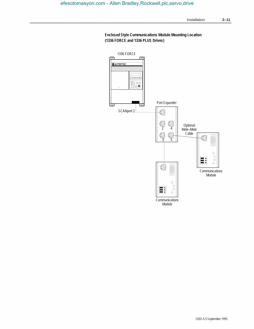
Enclosed Style Communications Module Mounting Location (1336 FORCE and 1336 PLUS Drives)
2
3
4
5
JOG
ESC SEL
SCANport 2
1336 FORCE
OptionalMale–Male
Cable
Port Expander
CommunicationsModule
CommunicationsModule
efesotomasyon.com - Allen Bradley,Rockwell,plc,servo,drive
2–12 Installation
1203–5.5 September 1995
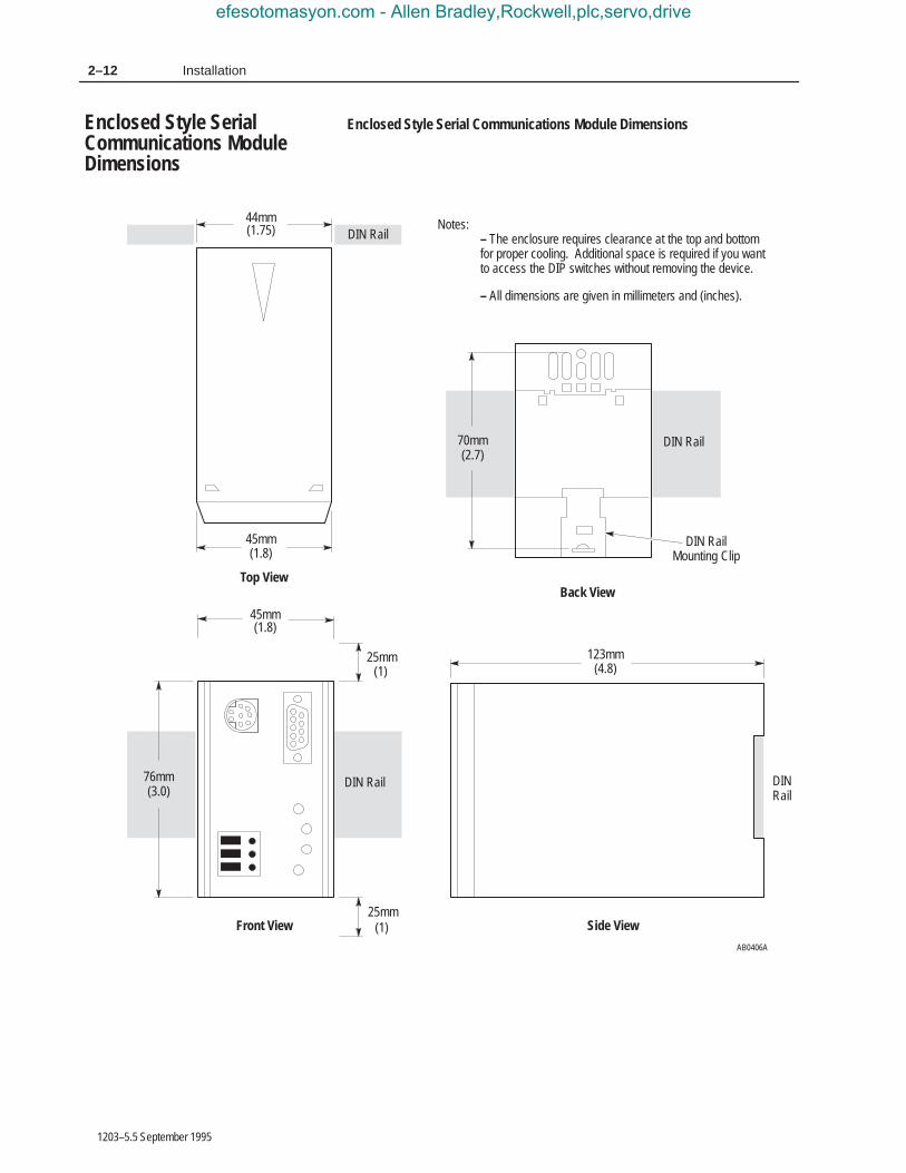
Enclosed Style Serial Communications Module Dimensions
DIN Rail
45mm(1.8)
Back View
(4.8)123mm
Side View
(1.8)45mm
(1.75)44mm Notes:
– The enclosure requires clearance at the top and bottom for proper cooling. Additional space is required if you want to access the DIP switches without removing the device.
– All dimensions are given in millimeters and (inches).
Front View
Top View
25mm(1)
DIN RailMounting Clip
25mm(1)
70mm(2.7)
DIN Rail
76mm(3.0)
DINRail
AB0406A
DIN Rail
DIN Rail
Enclosed Style SerialCommunications ModuleDimensions
efesotomasyon.com - Allen Bradley,Rockwell,plc,servo,drive

2–13Installation
1203–5.5 September 1995
This section provides information that you need to connect the cablesto your Serial Communications Module.
Important: When connecting your cables, you should make surethat the network is properly terminated. You shouldalso ground the shield at the end furthest from the SerialCommunications Module.
1746-BAS Module Serial Connections
Communications Module9-Pin D-Shell
1
2
3
4
59
8
7
654
3
2
1 6
7
8
9COM
N.C.TX
N.C.RX
N.C.N.C.
N.C.COM
COMN.C.
DTRCTS
TXRTS
RXDSR
N.C.
1746-BAS ModulePort Connection
Serial Communications Module to 1746-BAS ModulePRT1, PRT2 RS–232 Mode Port Connection Diagram
AB0401B
Communications Module9-Pin D-Shell
1
2
3
4
59
8
7
65
4
3
2
16
7
8
9COM
RXD –RXD +
N.C.SHIELD
N.C.TXD +
TXD –COM
COMTXD +
N.C.N.C.
N.C.N.C.
RXD –RXD +
TXD –
1746-BAS ModulePort Connection
Serial Communications Module to 1746-BAS ModulePRT1, PRT2 RS–422 Mode Port Connection Diagram
AB0402B
Communications Module9-Pin D-Shell
1
2
3
4
59
8
7
65
4
3
2
16
7
8
9COM
N.C.N.C.
N.C.SHIELD
N.C.TXD/RXD +
TXD/RXD –COM
COMTRXD +
N.C.N.C.
N.C.N.C.
N.C.N.C.
TRXD –
1746-BAS ModulePort Connection
Serial Communications Module to 1746-BAS ModulePRT1, PRT2 RS–485 Mode Port Connection Diagram
AB0403B
GND
GND
GND
Connecting Cables
efesotomasyon.com - Allen Bradley,Rockwell,plc,servo,drive

2–14 Installation
1203–5.5 September 1995
IBM PC Compatible Serial Connections
Communications Module9-Pin D-Shell
1
2
3
4
59
8
7
654
3
21 6
7
8
9COM
N.C.TX
N.C.RX
N.C.N.C.
N.C.COM
COMRI
DTRCTS
TXRTS
RXDSR
DCD
IBM AT CompatiblePersonal ComputerRS232 Serial Port
RS–485/RS–422/RS–232 Communications Adapter to IBM ATCompatible Computer RS–232 Serial Port Connection Diagram
Computer InternalJumper Connectors
AB0409D
GND
1747–AIC Link Coupler Serial Connections
Communications Module9-Pin D-Shell
1
2
3
4
59
8
7
6COM
N.C.N.C.
N.C.SHIELD
N.C.TRXD+
TRXD–COM
Phoenix 6–Point Connector1747–AIC Link Coupler
Serial Communications Module to 1747–AIC Link CouplerPRT1, PRT2 DH–485 Mode Port Connection Diagram
TERMABCOMMONSHLDCHS GND
efesotomasyon.com - Allen Bradley,Rockwell,plc,servo,drive

2–15Installation
1203–5.5 September 1995
PLC5 Channel 0 Serial Connections
Serial Communications Module to PLC5 RS–232Serial Port Connection Diagram
AB0486B
1
2
3
4
517
16
15
14C.GND
618
719
820
921
1022
1123
1224
1325
N.C.TXD
RESRXD
N.C.RTS
RESCTS
RESDER
N.C.SG.GND
DTRDCD
RESRES
N.C.N.C.
N.C.RES
RESRES
RESN.C.
Communications Module9-Pin D-Shell
PLC5/20, 5/40, 5/60, 5/80Channel 0
1
2
3
4
59
8
7
6COM
N.C.TX
N.C.RX
N.C.N.C.
N.C.COM
SLC 5/03 Port 1 Serial Connections
Communications Module9-Pin D-Shell
1
2
3
4
59
8
7
654
3
21 6
7
8
9COM
N.C.TX
N.C.RX
N.C.N.C.
N.C.
COMN.C.
DTRCTS
TXRTS
RXDSR
DCD
SLC 5/03 RS–232 Port
AB0411B
COM
efesotomasyon.com - Allen Bradley,Rockwell,plc,servo,drive

2–16 Installation
1203–5.5 September 1995
Cable Requirements
SCANport cables are available in either male–to–male or male–to–female configuration. You can connect cables of up to 10 meters (33feet) from the master to the SCANport device (A in the figurebelow). If you use a Port Expander (as shown in the figure below),you need to subtract the cable length from the master to the PortExpander from the cable length used to connect the device to theexpander (B1 + C = a maximum of ten meters).
1305 Drive
An Allen-Bradley SCANport link cable is used to connect the SerialCommunications Module to the drive (as shown below).
SCANport Connection on Serial Communications Module
1305 Drive
Human InterfaceModule
Port 1
A
Port 2
OptionalMale–Female
Cable
OptionalMale–Male
CableB1
Port Expander
B2
C
CommunicationsModule
CommunicationsModule
AB0407B
2
3
4
5
Important: The maximum cable distance between any two devicescannot exceed 10 meters (33 feet) of cable.
For example: A + B1 + C ≤ 10 metersA + B2 + C ≤ 10 metersB1 + B2 ≤ 10 meters
SCANport LinkConnection
efesotomasyon.com - Allen Bradley,Rockwell,plc,servo,drive

2–17Installation
1203–5.5 September 1995
1336 PLUS and 1336 FORCE
Refer to the product manual for connection information. On largerhorsepower 1336 PLUS and FORCE drives with an open SerialCommunications Module mounted in the drive, you do not need aseparate SCANport cable connection.
Connection information for the 1336 PLUS and 1336 FORCE isshown on page 2–11.
Important: The maximum cable distance between any two devicescannot exceed 10 meters (33 feet) of cable.
1394
Refer to the product manual for connection information.
SMP 3
An Allen-Bradley SCANport cable is used to connect the SerialCommunications Module to an SMP3.
Important: The maximum cable distance between any two devicescannot exceed 10 meters (33 feet) of cable.
SCANport Connection on Serial Communications Module
EnclosedCommunications Module
AB0408B
SMP 3
SMP3Connection
Port 1
Port 2
Human InterfaceModule
efesotomasyon.com - Allen Bradley,Rockwell,plc,servo,drive

2–18 Installation
1203–5.5 September 1995
The Enclosed Communications Module is powered from a separate24V DC or 115/230V AC power supply (as shown below). With theOpen Style Communications Module board mounted in the drive, noseparate power supply connections are required.
Typical Power Supply Connection
AB0413B
115/230VTypical
Connection
115V AC Hi115V AC Low
EnclosedCommunications Module
24VDC
PowerSupply
+–G
+_
24V DCTypical
Connection
GND
LNG
GND EnclosedCommunications Module
Power SupplyConnections
efesotomasyon.com - Allen Bradley,Rockwell,plc,servo,drive

Chapter 3
1203–5.5 September 1995
SCANport Datalink Operation
In this chapter, you will read about SCANport Datalinks.
A Datalink is a type of pointer function used by some SCANportdevices to transfer parameter values to and from the SCANportdevice. The Datalink function transfers parameters on a regularschedule. Reading a parameter using the Datalink function (datatable N41) requires less time than reading a parameter using theParameter Value Read data table addresses (data tables N10 – N19 orN50 – N89) because the module is kept updated on the parametervalue.
SCANport devices that support this function have a group ofparameters for Datalink configuration. These parameters areidentified as Datalink In and Datalink Out parameters. To enable theDatalink functions, you need to:
1. Set the correct switch to Enable on SW3 of the SerialCommunications Module.
2. Configure the Datalink In and Datalink Out parameters in theSCANport device.
Each Datalink consists of two 16-bit words of input and two 16-bitwords of output. You can configure each of the two input words towrite to a different destination parameter within the SCANportdevice by setting the two Datalink In parameters for that Datalink tothe desired destination parameters. Similarly, you can configure eachof the two output words by setting the two Datalink Out parametersfor that Datalink.
Each Datalink switch on SW3 can enable or disable one Datalink.
• If a Datalink is enabled, the value of the parameters set into theDatalink Out parameters is transferred to the SerialCommunications Module and the data sent by the SerialCommunications Module for the Datalink is transferred into theparameters set into the Datalink In parameters.
• If a Datalink is not enabled, the data transferred to the SCANportdevice for that Datalink is zero and the Serial CommunicationsModule ignores any data sent by the SCANport device.
If no Datalink In parameter is configured for an input word, thatword is ignored. If no Datalink Out parameter is configured for anoutput word, the output word is undefined (usually set to zero).
Chapter Objectives
SCANport Datalinks
efesotomasyon.com - Allen Bradley,Rockwell,plc,servo,drive

3–2 SCANport Data Link Operation
1203–5.5 September 1995
efesotomasyon.com - Allen Bradley,Rockwell,plc,servo,drive

Chapter 4
1203–5.5 September 1995
Configuring and Interfacing
This chapter provides you with information on how the SerialCommunications Module communicates with a serial device. Thefollowing topics are explained:
• Serial Communications Module data table structure
• configuration examples
!ATTENTION: When you configure a system for thefirst time, you should disconnect the motor from themachine or the process during the initial testing.
The Serial Communications Module maintains a data table thatallows the module to communicate with serial devices using standardPCCC commands.
Chapter Objectives
Serial CommunicationsModule Data TableStructure
efesotomasyon.com - Allen Bradley,Rockwell,plc,servo,drive

4–2 Configuring and Interfacing
1203–5.5 September 1995
Supported PCCC Command List
The Serial Communications Module supports the following PCCCCommands:
CMD Code FNC Code Command Name PLC Addressing Method
01h n/a Unprotected read PLC–2 address
06h 00h Echo n/a
01h Read diagnostic counters Variable (modified PLC–2 addresses)
02h Set variables (#ENQs, #NAKs, TIMEOUT) n/a
03h Identify host and some status n/a
04h Set timeout n/a
05h Set #NAKs n/a
06h Set #ENQs n/a
07h Reset diagnostic counters n/a
09h Read link parameters Logical address
0Ah Set link parameters Logical address
08h n/a Unprotected write PLC–2 address
0Fh 67h Typed write System address (4 possibilities)
68h Typed read System address (4 possibilities)
A1hProtected typed logical read with twoaddress fields
File number/type/element number
A2hProtected typed logical read with threeaddress fields
File number/type/elementnumber/sub–element number
A9hProtected typed logical write with twoaddress fields
File number/type/element number
AAhProtected typed logical write with threeaddress fields
File number/type/element number/sub–element number
ABhProtected typed logical write with fouraddress fields
File number/type/element number/sub–element number/bit mask
efesotomasyon.com - Allen Bradley,Rockwell,plc,servo,drive

4–3Configuring and Interfacing
1203–5.5 September 1995
Data Table Structure
The Serial Communications Module provides the following datatable structures for DF1 and DH–485.
The following table is the drive control table (binary file).
FileAddress
DescriptionFile
AddressDescription
B3:0 Logic Command B3:10 Logic Status
B3:1 Reference B3:11 Feedback
B3:2 Datalink A1 In (to Drive) B3:12 Datalink A1 Out (from Drive)
B3:3 Datalink A2 In (to Drive) B3:13 Datalink A2 Out (from Drive)
B3:4 Datalink B1 In (to Drive) B3:14 Datalink B1 Out (from Drive)
B3:5 Datalink B2 In (to Drive) B3:15 Datalink B2 Out (from Drive)
B3:6 Datalink C1 In (to Drive) B3:16 Datalink C1 Out (from Drive)
B3:7 Datalink C2 In (to Drive) B3:17 Datalink C2 Out (from Drive)
B3:8 Datalink D1 In (to Drive) B3:18 Datalink D1 Out (from Drive)
B3:9 Datalink D2 In (to Drive) B3:19 Datalink D2 Out (from Drive)
Note: If you write to B3:0 through B3:9, you will write data to thedrive. If you read from B3:0 through B3:9, you will return the databeing currently sent to the drive. If you read from B3:10 throughB3:19, you will read data from the drive. If you write to B3:10through B3:19, you will receive an error.
The following table is the drive control table (integer file).
File Address Description
N41:0 Logic Command/Status
N41:1 Reference/Feedback
N41:2 Datalink A1
N41:3 Datalink A2
N41:4 Datalink B1
N41:5 Datalink B2
N41:6 Datalink C1
N41:7 Datalink C2
N41:8 Datalink D1
N41:9 Datalink D2
Note: If you write to any location in N41, you will write data to thedrive. If you read from any location in N41, you will read data fromthe drive.
�
�
efesotomasyon.com - Allen Bradley,Rockwell,plc,servo,drive

4–4 Configuring and Interfacing
1203–5.5 September 1995
Important: The following two tables list the typical control andstatus structure. You should refer to your drive manualfor the actual control and status structures for yourdevice.
The following are the bit definitions for B3:0 or writes to N41:0:
Bit Description Bit Description
00 Stop 10 Acceleration time
01 Start 11 Acceleration time
02 Jog 12 Deceleration time
03 Clear faults 13 Deceleration time
04 Direction 14 Reference select
05 Direction 15 Reference select
06 Local 16 Reference select
07 MOP increment 17 MOP decrement
The following are the bit definitions for B3:10 or reads from N41:0:
Bit Description Bit Description
00 Enabled 10 At speed
01 Running 11 Local
02 Command direction 12 Local
03 Actual direction 13 Local
04 Accelerating 14 Reference select
05 Decelerating 15 Reference select
06 Alarm 16 Reference select
07 Faulted 17 Reference select
efesotomasyon.com - Allen Bradley,Rockwell,plc,servo,drive

4–5Configuring and Interfacing
1203–5.5 September 1995
The following is the data table structure for PLC–2 style addressing:
ParameterNumber
PLC–2 Style AddressDecimal (Octal)
Description of Location’s Purpose
1 – 7039 512 + Parm #(1000 to 16577)
Parameter value read
(16600 to 167770 Status of last parameter write
1 – 7039 7680 + Parm #(17000 to 34577)
Parameter read full
(34600 to 34677) Block transfer emulation area
(34700) Logic command/status
(34701) Reference/feedback
(34702) Datalink A1
(34703) Datalink A2
(34704) Datalink B1
(34705) Datalink B2
(34706) Datalink C1
(34707) Datalink C2
(34710) Datalink D1
(34711) Datalink D2
(34712) #ENQs
(34713) #NAKs
(34714) Message TIMEOUT (mS)
(34715) Application TIMEOUT (seconds)
(34716) Adapter series number (2=B)
(34717) Adapter firmware version (201=FRN2.01)
(34720) Maximum node address (DH–485)
(34721 to 37677) Reserved area for future expansion
(37700 to 37777) System area
Note: The address locations shown in this table are not limited toPLC–2 commands and may be used by any device that can generatethem.
�
efesotomasyon.com - Allen Bradley,Rockwell,plc,servo,drive

4–6 Configuring and Interfacing
1203–5.5 September 1995
The following is the data table structure for the SerialCommunications Module:
Parameter Number File Addresses Description of Location’s Purpose
1 – 999 N10:1 – 999
1000 – 1999 N11:0 – 999 Parameter
– – value
8000 – 8999 N18:0 – 999 read or write
9000 – 9999 N19:0 – 999
1 – 249 N50:1 – 249
250 – 499 N51:0 – 249 Parameter
– – value
9500 – 9749 N88:0 – 249 read or write
9750 – 9999 N89:0 – 249
N20:0 – 127 Status of last parameter write
1–999 N30:1 – 999
1000 – 1999 N31:0 – 999 Parameter
– – read
8000 – 8999 N38:0 – 999 full
9000 – 9999 N39:0 – 999
1 – 249 N90:1 – 249
250 – 499 N91:0 – 249 Parameter
– – read
9500 – 9749 N128:0 – 249 full
9750 – 9999 N129:0 – 249
N40:0 – 63 Block transfer emulation area
N41:0 Logic command/status
N42:0 #ENQs
N42:1 #NAKs
N42:2 Message TIMEOUT (mS)
N42:3 Application TIMEOUT (Seconds)
N42:4 Adapter series number (2 = B)
N42:5 Adapter firmware version (201=FRN2.01)
N42:6 Maximum node address (DH–485)
System File 0(or N200:1 – 63)
Station name (DF1)SLC compatible system file (DH–485)
Note: Some devices cannot access an element number over 254.The files from N50 to N129 are intended for use with those devices.
�
efesotomasyon.com - Allen Bradley,Rockwell,plc,servo,drive
4–7Configuring and Interfacing
1203–5.5 September 1995
The data tables have up to eight areas, each having a differentpurpose.
1. Parameter Value Read or Write (N10 – N19, N50 – N89). Reading data from files in this area will cause the SerialCommunications Module to read parameter values from theSCANport device and send those values as the response to theread message. Writing data to files in this area will cause theSerial Communications Module to write that data into SCANportdevice parameters.
2. Status of Last Parameter Write (N20). This area is read-only.When read, the data returned contains status information from thelast parameter write that was performed by the SerialCommunications Module. If no errors occurred during the write,all of the data returned will be zeros. Read this area beginning atelement number zero.
3. Parameter Read Full (N30 – N38, N90 – N129). This area isread-only. When read, the data returned consists of 20 words (40bytes) of information about each parameter including scaling,parameter text, units text, minimum, maximum, and defaultvalues. When reading this area, set the number of elements totwenty times the number of parameters to be read.
4. Block Transfer Emulation Area (N40). This area provides amethod for sending and receiving SCANport messages to andfrom the SCANport device. This allows you to perform everySCANport command the device supports. Chapter 5 providesinformation about the block transfer emulation functionsavailable for use with the Serial Communications Module.
To send a SCANport message, write data into this area beginningwith element number zero. Allow sufficient time for theSCANport device to respond to the message and then read theresponse message from this area beginning with element numberzero.
5. Producer/Consumer Emulation Area (N41). Each element inthis area has a different function. Refer to the DIP switchconfiguration tables in Chapter 3 for more information.
– Logic Command/Status. Writing sends a Logic Commandto the drive. Reading supplies the SCANport device LogicStatus. Refer to the manual supplied with the SCANportdevice for more information.
– Reference/Feedback. Writing sends a reference to theSCANport device. Reading supplies feedback from theSCANport device. The meaning of the reference andfeedback values depend on the type of SCANport device.
efesotomasyon.com - Allen Bradley,Rockwell,plc,servo,drive
4–8 Configuring and Interfacing
1203–5.5 September 1995
– Datalink A1. Writing to Datalink A1 sends a value to theparameter pointed to by the DataIn A1 parameter of theSCANport device. Reading from Datalink A1 reads thevalue of the parameter pointed to by the DataOut A1parameter of the SCANport device.
– Datalink A2 through Datalink D2 function the same asDatalink A1.
6. Serial Communications Module Parameters (N42). Each ofthe four elements in this area can be read or written and affectsthe operation of the Serial Communications Module as follows:
– Number of ENQ’s. The number of ENQ’s sent by themodule before giving up on receiving ACK or NAK. Thedefault is 3.
– Number of NAK’s. The number of times the module willresend a message if the response is always NAK. Thedefault is 3.
– Message Timeout. The number of milliseconds the modulewill wait before sending an ENQ. The default is 100mS.
– Application Timeout. The number of seconds the modulewill wait between messages before faulting the SCANportdevice it is connected to. The default is set by theconfiguration DIP switches.
– Adapter Series Number. The series letter of the 1203Serial Communications Module expressed as a number.For example, 1=A, 2=B, and so forth.
– Adapter Firmware Version. The firmware version numberof the 1203 Serial Communications Module. For example,201=FRN2.01, 202=FRN2.02, and so forth.
– Maximum Node Address. When in DH–485 mode, thisparameter sets the maximum node address that the adapterwill attempt to communicate with. The default value is 31(decimal).
7. Reserved for Future Expansion. If you try a read or write toany address in this area, the Serial Communications Module willrespond with an error message.
8. System Area. Performing a read from this area will cause theSerial Communications Module to respond with a 22-characterstring. This string is set at power-up to contain the Product TextString from the SCANport device with /1203 appended to it.Writing to this area changes the characters contained in the string.Cycling power returns the string to its original text.
efesotomasyon.com - Allen Bradley,Rockwell,plc,servo,drive

4–9Configuring and Interfacing
1203–5.5 September 1995
DF1 Messaging with a PLC–5/80 Example
This example reads parameters 1 through 50.
Ladder rung example for Gx2 manual
Rung 2:0
| I:000 MG20:0 B3 +MSG––––––––––––––––––––+ |+––] [–––]/[–––[ONS]––––––––––––––––––––––––––––+SEND/RECEIVE MESSAGE +–(EN)–+| 00 EN 2 |Control block MG20:0+–(DN) || | +–(ER) || +–––––––––––––––––––––––+ |
Data Table Report
MESSAGE INSTRUCTION DATA MONITOR FOR CONTROL BLOCK MG20:0
Communication Command: PLC–5 TYPED READPLC–5 Data Table Address: N30:0 ignore if timed–out: 0 TOSize in Elements: 50 to be retried: 0 NRLocal/Remote: LOCAL awaiting execution: 0 EW
Remote Station: N/A continuous: 0 COLink ID: N/A error: 0 ERRemote Link Type: N/A message done: 0 DN
Local Node Address: 001 message transmitting: 0 STDestination Data Table Address: N10:1 message enabled: 0 ENPort Number: 00
Error Code: 0000 (HEX)
Configuration Examples
efesotomasyon.com - Allen Bradley,Rockwell,plc,servo,drive

4–10 Configuring and Interfacing
1203–5.5 September 1995
Notes:
• I:000/00 is any application–related conditioning logic.
• MG20:0.EN is the enabled status bit from the message block.
• B3/2 is a one-shot that causes the message to be resent each timethe message block completes or errors (as long as I:000/00 istrue).
• The DF1 address of the PLC-5 is the same as its DH+ address (setby DIP switch SW1 on the PLC-5).
• Refer to Publication 6200–6.4.11, Instruction Set Reference, forinformation on the MSG block.
• Refer to Publication 1785–6.6.1, Hardware Installation Manual,for information on configuring the PLC-5 Channel 0 hardware.
• Refer to Publication 6200–6.4.6, Software Configuration andMaintenance, for information on configuring the PLC-5 Channel0 driver.
• Only one message may be active to a Serial CommunicationsModule at any time. When you write the PLC program, you mustensure this requirement.
efesotomasyon.com - Allen Bradley,Rockwell,plc,servo,drive

4–11Configuring and Interfacing
1203–5.5 September 1995
DF1 Messaging with a 1746–BAS Module Example
This example accepts a parameter number and a value from a userterminal and writes the data out to a SCANport–compatible device.
100 REM _____________________________________________________________101 REM __ This program inputs a parameter number and a value 102 rem __ from a user terminal and writes it out to a scanport103 rem __ compatible device.104 rem __ for 1746–BAS and 1203–GD2 modules105 rem _____________________________________________________________110 STRING 512,127140 REM150 REM ––––––––––––––––––––––––––––––––––––––––––––––––––––––––––––––160 REM Setup port 1 to 9600 baud, no parity, 8 bits, 1 stop bit,170 REM software handshaking, and battery backed ram data storage.180 REM !!!!REMEMBER TO SET TERMINAL TO MATCH!!!!190 REM ––––––––––––––––––––––––––––––––––––––––––––––––––––––––––––––200 MODE (PRT1,9600,N,8,1,S,R)210 REM ––––––––––––––––––––––––––––––––––––––––––––––––––––––––––––––220 REM230 REM Setup port 2 to 300 baud, no parity, 8 bits, 1 stop bit,240 REM software handshaking, and battery backed ram data storage.250 REM260 REM ––––––––––––––––––––––––––––––––––––––––––––––––––––––––––––––270 MODE (PRT2,300,N,8,1,S,R)280 REM ––––––––––––––––––––––––––––––––––––––––––––––––––––––––––––––290 REM300 REM Enable DF1 driver310 REM (20 = Setup for Full Duplex, Auto–Detect Embedded Responses,320 REM Disable Duplicate Packet Detection, BCC error checking)330 REM (200 = Wait 1 second for polling by Master)340 REM (2 = 2 retries)350 REM (0= No RTS on delay)360 REM (0 = No RTS off delay)370 REM (8 = 1746–BAS module address)380 REM ––––––––––––––––––––––––––––––––––––––––––––––––––––––––––––––390 PUSH 20400 PUSH 200410 PUSH 2420 PUSH 0430 PUSH 0440 PUSH 8450 CALL 108460 REM __________________ end df1 config _____________________________461 Print: print ”A negative parameter number exits the program ”470 INPUT ”Offset (Parameter Number)? ”,PAR_NUM 475 IF (PAR_NUM<0) THEN GOTO 530480 INPUT ”Control (parameter value)? ”,PAR_VALUE481 REM encode the value as an ASCII hex string in order of LOW, HIGH490 ASC($(1),1)=PAR_VALUE–(INT(PAR_VALUE/256)*256)500 ASC($(1),2)=INT(PAR_VALUE/256)510 GOSUB 550 : REM fire off the write instruction520 GOTO 460530 CALL 113540 END
efesotomasyon.com - Allen Bradley,Rockwell,plc,servo,drive

4–12 Configuring and Interfacing
1203–5.5 September 1995
550 REM ****************************************************************560 REM ********* PLC TYPED READ Subroutine *****561 REM ********* inputs Parameter number in var PAR_NUM *****562 REM ********* ASC coded hex string of value in $(1) *****563 REM ********* outputs: failure message *****565 REM ****************************************************************570 REM subroutine to do a typed write of a single parameter580 PRINT ”Executing PLC Remote Write ”600 PUSH 5 : REM PLC5 Typed Write610 PUSH 1 : REM Communications Module Node Address620 PUSH 10 : REM File Number ( atterss is N10:PAR_NUM) 630 PUSH ASC(N) : REM Communications Module File Type640 PUSH PAR_NUM : REM Starting Word in File650 PUSH 1 : REM Number of Words to Transfer (one parameter)660 PUSH 50 : REM Command Time–out (x100ms)670 PUSH 2 : REM Data Source (2 = Internal String)680 PUSH 0 : REM Offset in M0 file (Not used in this example)690 PUSH 1 : REM String # ASCII hex number order low, high700 CALL 123 : REM Builds the message to be sent710 POP S720 PUSH 123 : REM sets up call 29730 CALL 29 : REM send the message750 RETURN760 REM *********** End Write parameter subroutine *********
efesotomasyon.com - Allen Bradley,Rockwell,plc,servo,drive

4–13Configuring and Interfacing
1203–5.5 September 1995
DH–485 Messaging with a SLC5/03 Interface
The following example uses the DH–485 communications mode tosend a message from an SLC5/03 to the Serial CommunicationsModule.
Rung 2:0If this is the first scan or the error bit is true, the MSG instruction’s controlbyte is cleared and the done bit is set. This ensures that the program alwaysstarts correctly and recovers from a MSG error.| First || Scan || Bit || S:1 +AND–––––––––––––––+ ||–+––––] [–––––+––––––––––––––––––––––––––––––––––––––+–+BITWISE AND +–+–|| | 15 | | |Source A 255| | || | | | | | | || | | | |Source B N15:0| | || | | | | 8192| | || | | | |Dest N15:0| | || | | | | 8192| | || | | | +––––––––––––––––––+ | || | MSG Block | | MSG Block | || | Error (ER) | | Done (DN) | || | Bit | | Bit | || | N15:0 | | N15:0 | || +––––] [–––––+ +––––(L)–––––––––––––––+ || 12 13 |
Rung 2:1When the MSG instruction is done, the TON provides a 2 second delay before anothermessage is sent. B3:0/0 represents user logic. The timer can be adjusted toprovide control over DH485 network loading.| User |MSG Block || DH485 |Done (DN) || Enable |Bit || B3:0 N15:0 +TON–––––––––––––––+ ||––––] [––––––––] [––––––––––––––––––––––––––––––––––+TIMER ON DELAY +–(EN)–|| 0 13 |Timer T4:0+–(DN) || |Time Base 0.01| || |Preset 200| || |Accum 156| || +––––––––––––––––––+ |
efesotomasyon.com - Allen Bradley,Rockwell,plc,servo,drive

4–14 Configuring and Interfacing
1203–5.5 September 1995
Rung 2:2When the timer is done, the MSG instruction is enabled.| TON Done – || Enable || MSG Block || T4:0 +MSG––––––––––––––––––––+ ||––––] [––––––––––––––––––––––––––––––––––––––––+READ/WRITE MESSAGE +–(EN)–|| DN |Type PEER–TO–PEER+–(DN) || |Read/Write WRITE+–(ER) || |Target Device 500CPU| || |Local/Remote LOCAL| || |Control Block N15:0| || |Control Block Length 14| || +–––––––––––––––––––––––+ |
Rung 2:3| ||–––––––––––––––––––––––––––––––––––––+END+––––––––––––––––––––––––––––––––––––|| |
The following are the data tables used for this example:
Address Data (Radix=BINARY) Address Data (Radix=BINARY)B3:0 0000 0000 0000 0001
Address EN TT DN TIME BASE PRE ACCT4:0 1 1 0 .01 sec. 200 156
Address CU CD DN OV UN UA PRE ACCC5:0 0 0 0 0 0 0 32767 2778
Address Data (Radix=DECIMAL)N10:0 7 6 0 0 0 0 0 0 0
Address Data (Radix=DECIMAL)N15:0 8192 3 9 10 137 5 0 224 10 0N15:10 0 0 0 0
M0:1 File Length:64M0:2 File Length:0M0:3 File Length:0M0:4 File Length:0
M1:1 File Length:64M1:2 File Length:0M1:3 File Length:0M1:4 File Length:0
efesotomasyon.com - Allen Bradley,Rockwell,plc,servo,drive

Chapter 5
1203–5.5 September 1995
Block Transfer EmulationInstructions
This chapter contains the header and data configurations that youneed to set up the data files for the block transfer emulationinstructions. The header and data values depend on the operationyou want to perform.
When an operation is unsuccessful, header word 2 of the driveresponse contains a negative value (bit 15 = 1).
In most cases, the drive also returns a status word to indicate thereason for the failure. The location of the status word is typicallyheader word 4 in the drive response, but will depend on the message.
The following are valid status codes:
Value Description
0 No error occurred.
1The service failed due to an internal reason, and the drive could not performthe request (some messages are read only or write only).
2 The requested service is not supported.
3 An invalid value in the block transfer emulation request header word 2.
4 An invalid value in the block transfer emulation request header word 3.
5 An invalid value in the block transfer emulation request header word 2.
6 The data value is out of range.
7There is a drive state conflict. The drive is in an incorrect state to perform thefunction. The drive cannot be running when you perform certain functions.
Chapter Objectives
Block Transfer EmulationStatus Word
efesotomasyon.com - Allen Bradley,Rockwell,plc,servo,drive

5–2
1203–5.5 September 1995
The Scattered Parameter Value Read function reads a scattered list ofparameters.
PLC Block Transfer Emulation Instruction Data
PLC request instruction length: 5–63 wordsDrive response instruction length: 5–63 words
HeaderWord 1
PLC Decimal Value3
Message Structure
HeaderWord 2
DataWord 3
PLC Request
Header Word 1
Header Word 2
Data Word 3
Message LengthMessage Length
PLC Decimal Value3 –– Message OK
–32765 –– Message Error
Number of Parameter
Drive Response
Number of Parameter
5–63
Values to Read
0
Data Word 4
Data Word 5
Data Word 6
Parameter Number
Parameter Number
1
2
Parameter Number3
Data Word 7
Data Word 8
Data Word 9
0
0
Data Word 62Parameter Number30
Data Word 630
5 – 63
Values to Read
DataWord 4
DataWord 5
DataWord 6
Parameter Number
Parameter Value or
Parameter Number
1
2
DataWord 7
DataWord 8
DataWord 9
Parameter Value or
Parameter Value or
bit
Status Word1
Status Word2
Parameter Number3
Status Word3
15
bit15
bit15
DataWord 62
DataWord 63
Parameter Value or
Parameter Number30
Status Word30
bit15
•••
•••
•••
•••
•••
••• •
••
•••
Scattered Parameter ValueRead
efesotomasyon.com - Allen Bradley,Rockwell,plc,servo,drive

5–3Block Transfer Emulation Instructions
1203–5.5 September 1995
Message Operation
Scattered Parameter Value Read reads a pre–defined group ofparameter values, in any order, from the device. You define thenumber of parameters to read in word 3 of the request. Theparameters to be read and their order is defined starting with word 4.An unused word is left between each parameter request, so the drivecan respond with the parameter value, as shown.
If an error has occurred in reading any of the parameters:
• Word 2 of the drive response returns a value of –32765.
• Bit 15 of the drive response word for the number of thatparameter is set.
• The drive response word for the value of that parameter returns astatus word instead of returning the parameter value.
Example
In this example, eight parameters were read from a 1336 PLUSdrive, as defined in word 3 of the request. The parameter numbersrequested were 5, 7, 8, 20, 18, 17, 19, and 36. The drive responsereturned the values of these parameters in the data file. These valuesare in drive units.
Data File Format
19 3 8*
0 18* 0* 17*
* Example only – These values vary depending on parameters and products.
19 3
4096*4096* 18*
8*
5*
5*
17*
0
6*
51*
19*
7*
19*
0
1000*
60*
36*
8*
36*
0
1000*
6144*
20*
0 7* 0 8* 0 20*
0
N10:10
N10:20
1 2 3 4 5 6 7 8 9
N10:90
N10:100
PLC request
Drive response
efesotomasyon.com - Allen Bradley,Rockwell,plc,servo,drive

5–4
1203–5.5 September 1995
The Scattered Parameter Value Write function writes to a scatteredlist of parameters and returns the status of each parameter. If any ofthe states have errors, the parameter number is negative.
PLC Block Transfer Emulation Instruction Data
PLC request instruction length: 5–63 wordsDrive response instruction length: 5–63 words
HeaderWord 1
PLC Decimal Value–32765
Message Structure
HeaderWord 2
DataWord 3
PLC Request
Header Word 1
Header Word 2
Data Word 3
Message LengthMessage Length
PLC Decimal Value3 –– Message OK
–32765 –– Message Error
Number of Parameter
Drive Response
Number of Parameter
5–63
Values to Write
Parameter Value
Data Word 4
Data Word 5
Data Word 6
Parameter Number
Parameter Number
1
2
Parameter Number3
Data Word 7
Data Word 8
Data Word 9
Parameter Value
Parameter Value
Data Word 62Parameter Number30
Data Word 63Parameter Value
5 – 63
Values to Write
DataWord 4
DataWord 5
DataWord 6
Parameter Number
Parameter Number
1
2
DataWord 7
DataWord 8
DataWord 9
bit
Status Word 1
Status Word 2
Parameter Number3
Status Word 3
15
bit15
bit15
DataWord 62
DataWord 63
Parameter Number30
Status Word 30
bit15
•••
•••
•••
•••
•••
••• •
••
•••
1
2
3
30
Scattered Parameter ValueWrite
efesotomasyon.com - Allen Bradley,Rockwell,plc,servo,drive

5–5Block Transfer Emulation Instructions
1203–5.5 September 1995
Message Operation
The Scattered Parameter Value Write function writes data values to apre–defined group of device parameters in any order. You define thenumber of parameters to write in word 3. The parameters to bewritten to and their order is defined starting with word 4.
If an error occurs while writing to any of the parameters:
• Word 2 of the drive response returns a value of –32765.
• Bit 15 of the drive response word for that parameter’s number isset.
• The drive response word for that parameter’s status word isnon–zero.
If no error has occurred:
• Word 2 of the drive response returns a value of 3.
• Each of the drive response’s parameter numbers are the same asin the request.
• Each of the drive response status words returns a value of 0.
Example
In this example, six parameters were written to in a 1336 PLUSdrive. Word 3 of the request (N10:12) defines the number ofparameter values that are transferred. Each parameter numberfollowed by its value, are listed in the message beginning with word4. The values are entered in device units.
The drive response (N10:90) returns the status of each parameterwrite. If the request was successful, a zero is returned. If an errorhas occurred, the response returns a status word code for the error.
Data File Format
15 –32765 6*
10* 10* 2* 12*
* Example only – These values vary depending on parameters and products.
15 3 6*
0* 10* 0*
90*
90*
12*
5*
0*
0*
1*
150* 0* 30* 0*
150* 4* 30* 20*
N10:90
N10:100
0
N10:0
N10:20
1 2 3 4 5 6 7 8 9
PLC request
Drive response 31*
31*
efesotomasyon.com - Allen Bradley,Rockwell,plc,servo,drive

5–6
1203–5.5 September 1995
The Product ID Number Read function returns the product ID of thedevice to which the Serial Communications Module is connected.
PLC Block Transfer Emulation Instruction Data
PLC request instruction length: 3 wordsDrive response instruction length: 4 words
HeaderWord 1
PLC Decimal Value256
Message Structure
HeaderWord 2
HeaderWord 3
PLC Request
Header Word 1
Header Word 2
Data Word 3
Message LengthMessage Length
PLC Decimal Value256 –– Message OK
–32512 –– Message Error
0
Drive Response
3
0
Product ID Number Description
23451617181920212223
1336F (PLUS Fractional)1336F (PLUS)1336G (FIBERS Fractional)1336G (FIBERS)1336T (FORCE)139513941557SMPSMC13041305
6
DataWord 4
Product ID Number
Message Operation
The Product ID Number Read function, through the drive responsemessage word 4, indicates the type of device the SerialCommunications Module is connected to. This value is defined inthe message response chart shown above.
If an error has occurred, word 2 of the response returns a negativevalue of –32512.
Product ID Number Read
efesotomasyon.com - Allen Bradley,Rockwell,plc,servo,drive

5–7Block Transfer Emulation Instructions
1203–5.5 September 1995
Example
In this example, the Product ID Number Read was requested. Thedrive response contained a value of 3 in word 4 of its messageresponse, indicating a connection to a 1336 PLUS.
Data File Format
3*
3 0
* Example only – These values vary depending on parameters and products.
6 0
0
N10:0
N10:90
1 2 3 4 5 6 7 8 9
PLC request
Drive response256
256
efesotomasyon.com - Allen Bradley,Rockwell,plc,servo,drive

5–8
1203–5.5 September 1995
The Parameter Read Full function provides all known attributes forthe parameters requested. This information includes the parameter’scurrent value, descriptor, multiply and divide value, base value,offset value, text string, group element reference, minimum value,maximum value, default value, and unit text string.
PLC Block Transfer Emulation Instruction Data
PLC request instruction length: 3 wordsDrive response instruction length: 20 words
DataWord 1
PLC Decimal Value768
Message Structure
DataWord 2
DataWord 3
PLC Request
Header Word 1
Header Word 2
Data Word 3
Parameter ValueMessage Length
Descriptor
Multiply Value
Drive Response
Parameter Number
3
(See Drive List)
or Status Word
DataWord 4
DataWord 5
Divide Value
Base Value
DataWord 6
DataWord 7
Offset Value
Parameter Text
Char 2 Char 1
DataWord 8
Parameter Text
Char 4 Char 3
DataWord 9
Parameter Text
Char 6 Char 5
DataWord 10
Parameter Text
Char 8 Char 7
DataWord 11
Parameter Text
Char 10 Char 9
DataWord 12
Parameter Text
Char 12 Char 11
DataWord 13
Parameter Text
Char 14 Char 13
DataWord 14
Parameter Text
Char 16 Char 15
Parameter Read Full
efesotomasyon.com - Allen Bradley,Rockwell,plc,servo,drive

5–9Block Transfer Emulation Instructions
1203–5.5 September 1995
Message Structure (Continued)
DataWord 15
DataWord 16
File, Group, Element
Minimum Value
Drive Response
DataWord 17
DataWord 18
Maximum Value
Default Value
DataWord 19
Unit Text
Char 2 Char 1
DataWord 20
Unit Text
Char 4 Char 3
Message Operation
Parameter Read Full retrieves the attributes of the specifiedparameter. The attributes for each parameter include the data,minimum and maximum values, and the parameter text. Theresponse message returns this information.
If an error has occurred in reading any of the values, word 1 containsthe status word.
The parameter text is returned with each data word containing twoASCII characters per word. The first and second characters are inopposite order.
Example
In this example, a Parameter Read Full was performed through blocktransfer on a 1336 PLUS. N10:10 shows the header message for therequest. The data is returned in the response data file, starting withword 1, for parameter 20. Word 1 shows the present value in driveunits. Word 2 through word 6 provide scaling information, used toconvert drive units to engineering units for the Human InterfaceModule (HIM). Word 7 through word 14 provide the parametername.
efesotomasyon.com - Allen Bradley,Rockwell,plc,servo,drive

5–10
1203–5.5 September 1995
This example shows the response message N10:90 through N10:112in both binary and ASCII. Note the ASCII information beginningwith N10:99. The parameter name characters return in reverse orderfor each word. N10:99 has the ASCII value of (aM). To read this,invert the word to read (Ma). The next word (ix), inverted gives you(xi). These words, along with the following two words, form theword Maximum. You can see the parameter name Maximum Voltagein word 7 through word 14 of the response message. In addition,word 20, is also returned in this format. This word provides the unitsthe parameter is defined in. In this example it is vlts.
Word 15 contains the file, group, and element which are used toreference the parameter.
Words 16–18 contain the minimum, maximum, and default values ofthis parameter.
Data File Format
0
N10:10
N10:90
1 2 3 4 5 6 7 8 9
3 768 20*
4096* 355* 1* 4096*
* Example only – These values vary depending on parameters and products.# ASCII Display values
N10:100
N10:90#
N10:100#
28502* 29804* 26465* 8293*
460*
1794*
0*
1024*
24909*
4915*
27000*
4096*
30061*
27734* 29556*
\10\00
o V
\01 ct l g a e 07 02 04 00 \13 0
\00\01 \01\CC \00\00 a M i x u m\10\00 m \10\00 l V s t
8301*
Drive response
Drive response
PLC request
efesotomasyon.com - Allen Bradley,Rockwell,plc,servo,drive

5–11Block Transfer Emulation Instructions
1203–5.5 September 1995
The Parameter Value Read function reads the 16–bit parameter datavalue for the selected parameter number.
PLC Block Transfer Emulation Instruction Data
PLC request instruction length: 3 wordsDrive response instruction length: 1 word
DataWord 1
PLC Decimal Value769
Message Structure
PLC Request
Header Word 1
Header Word 2
Header Word 3
Parameter Value or Message Length
Drive Response
Parameter Number
3
(See Drive List)
Status Word
Message Operation
Parameter Value Read reads parameter values from the drive andplaces that value (or an error code) in word 1 of the drive responsedata file. The value is shown in device units. Device units are listedin the user manual for the device you are using.
If an error occurs:
• Word 1 of the response contains the status code.
• The status area of the data file is non–zero.
Example
In this example, the value of parameter 20 was requested from a1336 PLUS and a value of 4096 was returned. 4096 is the internaldrive unit value for the Maximum Rated Voltage Parameter. Thiscorresponds to a value of 100% Drive Rated Volts in Display Units.
Data File Format
0
N10:10
N10:90
1 2 3 4 5 6 7 8 9
3 769 20*
4096*
* Example only – These values vary depending on parameters and products.
PLC request
Drive response
Parameter Value Read
efesotomasyon.com - Allen Bradley,Rockwell,plc,servo,drive

5–12
1203–5.5 September 1995
The Parameter Value Write message writes a 16–bit parameter datavalue to the selected parameter number.
PLC Block Transfer Emulation Instruction Data
PLC request instruction length: 1 wordDrive response instruction length: 4 words
HeaderWord 1
Message Structure
HeaderWord 2
DataWord 3
PLC Request
Data Word 1Message Length
Parameter Value
PLC Decimal Value769 –– Message OK
–31999 –– Message Error
Parameter Number
Drive Response
4
DataWord 4
Status Word
Message Operation
The Parameter Value Write function sends a new value to thespecified parameter. The value must be in device units. Units foreach parameter are listed in the device manual.
If an error has occurred, word 2 of the response returns a value of–31999, and word 4 contains a status code.
Example
In this example, a value of 4096 was sent to Parameter 20. 4096 isin drive units and indicates a value of 100% Drive Rated Volts, asdefined in P147, Drive Rated Volts.
Data File Format
0
N10:0
N10:90
1 2 3 4 5 6 7 8 9
4 –31999 20*
4 769 20* 0
* Example only – These values vary depending on parameters and products.
4096*PLC request
Drive response
Parameter Value Write
efesotomasyon.com - Allen Bradley,Rockwell,plc,servo,drive

5–13Block Transfer Emulation Instructions
1203–5.5 September 1995
The EE Memory Functions message activates the specified EEfunctions.
PLC Block Transfer Emulation Instruction Data
PLC request instruction length: 4 wordsDrive response instruction length: 3 words
HeaderWord 1
PLC Decimal Value–31998
Message Structure
HeaderWord 2
HeaderWord 3
PLC Request
Header Word 1
Header Word 2
Header Word 3
Message LengthMessage Length
PLC Decimal Value770 –– Message OK
–31998 –– Message Error
0
Drive Response
4
0
Header Word 4EE Command
Value EE Command
00010203
Not UsedEE SaveEE RecallEE Default Initialize
3
Message Operation
The EE memory function allows three different message requests:
• EE Save saves parameter information from the working memoryor RAM to EEPROM.
• EE Recall retrieves the last saved data from EEPROM and placesit in the working memory or RAM.
• EE Default Initialize clears the RAM and EEPROM and sets allparameter values to default.
If an error has occurred, word 2 of the response returns a value of–31998.
EE Memory Functions
efesotomasyon.com - Allen Bradley,Rockwell,plc,servo,drive

5–14
1203–5.5 September 1995
Example
This example requests that an EEPROM Save function beperformed.
Data File Format
0
N10:10
N10:90
1 2 3 4 5 6 7 8 9
* Example only – These values vary depending on parameters and products.
PLC request
Drive response
4
3
–31998
770
0*
0*
1*
efesotomasyon.com - Allen Bradley,Rockwell,plc,servo,drive

5–15Block Transfer Emulation Instructions
1203–5.5 September 1995
The Fault Clear/Reset message activates the Clear Fault, Clear FaultQueue, and Drive Reset functions.
PLC Block Transfer Emulation Instruction Data
PLC request instruction length: 4 wordsDrive response instruction length: 4 words
HeaderWord 1
PLC Decimal Value–30976
Message Structure
HeaderWord 2
DataWord 3
PLC Request
Header Word 1
Header Word 2
Header Word 3
Message Length
PLC Decimal Value1792 –– Message OK
–30976 –– Message Error
0
Drive Response
4
0
Data Word 4Fault Command
Value Fault Command
00010203
Not UsedClear FaultClear Fault QueueDrive Reset (1336 FORCE Only)
Message Length4
DataWord 4
Status Word
Message Operation
The specified fault Clear/Reset function sends a fault handlingrequest to the device.
• A Clear Fault request clears the last fault that occurred.
• A Clear Fault Queue clears the entire fault buffer. Certaindevices may store more than one fault.
• A Drive Reset is used with the 1336 FORCE drive product only.This function resets the drive; it clears the fault queue and writesthe parameter information stored in EEPROM to RAM.
Data File Format
4 –30976
* Example only – These values vary depending on parameters and products.
1,2,30
0
N10:0
1 2 3 4 5 6 7 8 9
PLC request
4 1792 0*0N90:0Drive response
Fault Clear/Reset
efesotomasyon.com - Allen Bradley,Rockwell,plc,servo,drive
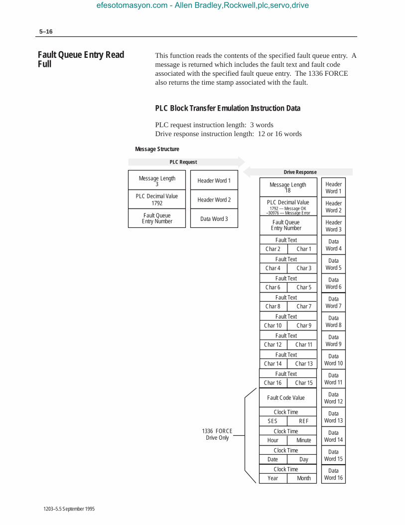
5–16
1203–5.5 September 1995
This function reads the contents of the specified fault queue entry. Amessage is returned which includes the fault text and fault codeassociated with the specified fault queue entry. The 1336 FORCEalso returns the time stamp associated with the fault.
PLC Block Transfer Emulation Instruction Data
PLC request instruction length: 3 wordsDrive response instruction length: 12 or 16 words
HeaderWord 1
PLC Decimal Value1792
Message Structure
HeaderWord 2
HeaderWord 3
PLC Request
Header Word 1
Header Word 2
Data Word 3
Message LengthMessage Length
PLC Decimal Value
Fault Queue
Drive Response
Fault Queue
3
Entry Number
18
DataWord 4
Fault Text
Char 2 Char 1
DataWord 5
Fault Text
Char 4 Char 3
DataWord 6
Fault Text
Char 6 Char 5
DataWord 7
Fault Text
Char 8 Char 7
DataWord 8
Fault Text
Char 10 Char 9
DataWord 9
Fault Text
Char 12 Char 11
DataWord 10
Fault Text
Char 14 Char 13
DataWord 11
Fault Text
Char 16 Char 15
1792 –– Message OK–30976 –– Message Error
Entry Number
DataWord 12
Fault Code Value
DataWord 13
Clock Time
SES REF
DataWord 14
Clock Time
Hour Minute
DataWord 15
Clock Time
Date Day
DataWord 16
Clock Time
Year Month
1336 FORCEDrive Only
Fault Queue Entry ReadFull
efesotomasyon.com - Allen Bradley,Rockwell,plc,servo,drive

5–17Block Transfer Emulation Instructions
1203–5.5 September 1995
Message Operation
Fault Queue Entry Read Full reads the contents of the fault queuespecified in word 3 of the request. The response returns the fault textwhich can be ASCII text. The text will have every two characters inreverse order. In addition, the 1336 FORCE returns a time stamp,indicating the day and time the fault occurred.
If an error has occurred, word 2 of the response returns a negativevalue.
Example
In this example, Fault Queue Entry number 3 was retrieved from a1336 PLUS drive. The drive response returned the ASCII text DriveReset Flt, with each character reversed. The fault code for thisexample is 22.
Data File Format
* Example only – These values vary depending on parameters and products.# ASCII Display values
8308* 22*
r D\00\12 \07\00
30313* 8293* 25938* 25971* 8308*
\03\00 v i l F e
t \00\16
27718*
e R e s t
3 1792 3*
18 1792 3* 29252*
0
N10:0
N10:90
1 2 3 4 5 6 7 8 9
PLC request
Drive response
N10:100
N10:90#
N10:100#
efesotomasyon.com - Allen Bradley,Rockwell,plc,servo,drive

5–18
1203–5.5 September 1995
The Fault Queue Size function gets the number of fault entriesallowed in the fault queue.
PLC Block Transfer Emulation Instruction Data
PLC request instruction length: 3 wordsDrive response instruction length: 4 words
HeaderWord 1
PLC Decimal Value1793
Message Structure
HeaderWord 2
DataWord 3
PLC Request
Header Word 1
Header Word 2
Header Word 3
Message LengthMessage Length
PLC Decimal Value1793 –– Message OK
–30975 –– Message Error
0
Drive Response
3
0
5
DataWord 4
Fault Queue Size
Message Operation
The Fault Queue Size function reads back the size of the fault queueavailable in the product. Each product may have a different numberof fault queue entries available for storage.
If an error has occurred, word 2 of the response returns a value of–30975.
Example
In this example, a 1336 PLUS was used. This product has a faultqueue of four storage locations available to store faults. This valueis seen in word 4 of the response header message.
Data File Format
3 1793 0
* Example only – These values vary depending on parameters and products.
6 1793 0 4*
0
N10:0
N10:90
1 2 3 4 5 6 7 8 9
PLC request
Drive response
Fault Queue Size
efesotomasyon.com - Allen Bradley,Rockwell,plc,servo,drive

5–19Block Transfer Emulation Instructions
1203–5.5 September 1995
The Trip Fault Queue Number provides the fault queue number ofthe fault that caused the device to trip.
PLC Block Transfer Emulation Instruction Data
PLC request instruction length: 3 wordsDrive response instruction length: 4 words
HeaderWord 1
PLC Decimal Value1794
Message Structure
HeaderWord 2
HeaderWord 3
PLC Request
Header Word 1
Header Word 2
Header Word 3
Message LengthMessage Length
PLC Decimal Value1794 –– Message OK
–30984 –– Message Error
0
Drive Response
3
0
4
HeaderWord 4
Number of Trip Fault
Message Operation
The Trip Fault Queue Number function provides the number of theentry in the fault queue that tripped the device in word 4 of the driveresponse. The Fault Queue Number is 0 when the device is notfaulted.
If an error has occurred in the block transfer, word 2 of the responseis negative.
Example
In this example, the device has stored a fault in the first entry of theFault Queue that caused the drive to trip. Word 4 of the responseindicates the entry number.
Data File Format
3 1794 0
* Example only – These values vary depending on parameters and products.
6 1794 0 1*
0
N10:0
N10:90
1 2 3 4 5 6 7 8 9
PLC request
Drive response
Trip Fault Queue Number
efesotomasyon.com - Allen Bradley,Rockwell,plc,servo,drive

5–20
1203–5.5 September 1995
efesotomasyon.com - Allen Bradley,Rockwell,plc,servo,drive

Chapter 6
1203–5.5 September 1995
Troubleshooting
Use this chapter to help you troubleshoot your SerialCommunications Module system using the LED indicators on thefront of the device (as shown below). The Serial CommunicationsModule is a non-serviceable device that you should return toAllen-Bradley for replacement when a major fault exists that isattributable to the Serial Communications Module itself.
LED Locations
Front View Enclosed Version
AB0414C
SCANport STSSerial STSTX
SW1SW2SW3
J4J2
Front View Open Version
RX
TXSerial STS
SCANport STSRX
Chapter Objectives
efesotomasyon.com - Allen Bradley,Rockwell,plc,servo,drive
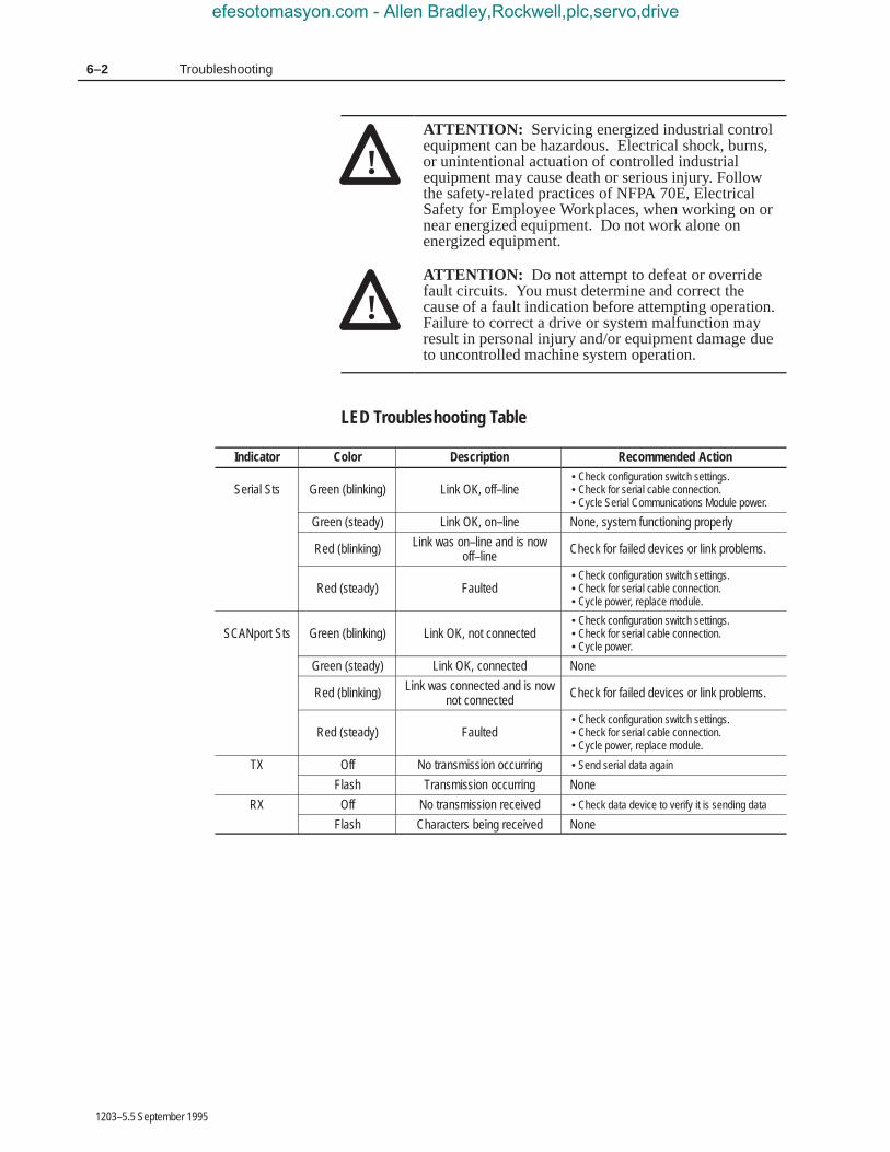
6–2 Troubleshooting
1203–5.5 September 1995
!ATTENTION: Servicing energized industrial controlequipment can be hazardous. Electrical shock, burns,or unintentional actuation of controlled industrialequipment may cause death or serious injury. Followthe safety-related practices of NFPA 70E, ElectricalSafety for Employee Workplaces, when working on ornear energized equipment. Do not work alone onenergized equipment.
!ATTENTION: Do not attempt to defeat or overridefault circuits. You must determine and correct thecause of a fault indication before attempting operation.Failure to correct a drive or system malfunction mayresult in personal injury and/or equipment damage dueto uncontrolled machine system operation.
LED Troubleshooting Table
Indicator Color Description Recommended Action
Serial Sts Green (blinking) Link OK, off–line• Check configuration switch settings.• Check for serial cable connection.• Cycle Serial Communications Module power.
Green (steady) Link OK, on–line None, system functioning properly
Red (blinking) Link was on–line and is nowoff–line
Check for failed devices or link problems.
Red (steady) Faulted• Check configuration switch settings.• Check for serial cable connection.• Cycle power, replace module.
SCANport Sts Green (blinking) Link OK, not connected• Check configuration switch settings.• Check for serial cable connection.• Cycle power.
Green (steady) Link OK, connected None
Red (blinking) Link was connected and is nownot connected
Check for failed devices or link problems.
Red (steady) Faulted• Check configuration switch settings.• Check for serial cable connection.• Cycle power, replace module.
TX Off No transmission occurring • Send serial data again
Flash Transmission occurring None
RX Off No transmission received • Check data device to verify it is sending data
Flash Characters being received None
efesotomasyon.com - Allen Bradley,Rockwell,plc,servo,drive

Chapter 7
1203–5.5 September 1995
Specifications
This chapter provides you with background information andspecifications that you may need to install or apply your SerialCommunications Module.
Product Specifications
Open StyleEnclosed Style 115/230V
ACEnclosed Style 24V DC
Catalog Number: –GM2 –GD2 –GK2
Environmental:
Operating Temperature 0 to 50° C (32 to 122°F) 0 to 50° C (32 to 122°F) 0 to 50° C (32 to 122°F)
Storage Temperature –40 to 85° C (–40 to 185°F) –40 to 85° C (–40 to 185°F) –40 to 85° C (–40 to 185°F)
Electrical:
Input Voltage Supplied by drive 85 to 264V AC, 1 phase 24V DC, ±10%
Input Frequency NA 45 to 63 Hz NA
Input Current NA 35mA maximum 0.4 amps maximum
SCANport Load 60mA DC 60mA DC 60mA DC
Communications:
SCANport Side SCANport PeripheralInterface
SCANport PeripheralInterface
SCANport PeripheralInterface
Serial SideRS–232/RS–422/RS–485
(DF1)DH–485
RS–232/RS–422/RS–485(DF1)
DH–485
RS–232/RS–422/RS–485(DF1)
DH–485
Baud Rates 110, 300, 600, 1200, 2400,4800, 9600, 19.2K
110, 300, 600, 1200, 2400,4800, 9600, 19.2K
110, 300, 600, 1200, 2400,4800, 9600, 19.2K
Checksum BCC or CRC BCC or CRC BCC or CRC
Dimensions:
Open (IP00) NEMA Type 1 (IP30) NEMA Type 1 (IP30)
NA 45w x 76h x 123d mm(1.8 x 3.0 x 4.8 in.)
45w x 76h x 123d mm(1.8 x 3.0 x 4.8 in.)
This module is intended for use with devices that communicate viaRS–232, RS–422, or RS–485 hardware standards using the DF1protocol or the DH–485 standard. The Serial CommunicationsModule is intended to provide a means for transmitting messagesbetween these serial communications devices and Allen-BradleySCANport devices.
Chapter Objectives
Module Compatibility
efesotomasyon.com - Allen Bradley,Rockwell,plc,servo,drive

7–2 Specifications
1203–5.5 September 1995
efesotomasyon.com - Allen Bradley,Rockwell,plc,servo,drive

1203–5.5 September 1995Template revised June 23,1995
Allen-Bradley, a Rockwell Automation Business, has been helping its customers improveproductivity and quality for more than 90 years. We design, manufacture and support a broadrange of automation products worldwide. They include logic processors, power and motioncontrol devices, operator interfaces, sensors and a variety of software. Rockwell is one of theworlds leading technology companies.
Worldwide representation.
Argentina • Australia • Austria • Bahrain • Belgium • Brazil • Bulgaria • Canada • Chile • China, PRC • Colombia • Costa Rica • Croatia • Cyprus • Czech Republic •Denmark • Ecuador • Egypt • El Salvador • Finland • France • Germany • Greece • Guatemala • Honduras • Hong Kong • Hungary • Iceland • India • Indonesia • Ireland • Israel • Italy • Jamaica • Japan • Jordan • Korea • Kuwait • Lebanon • Malaysia • Mexico • Netherlands • New Zealand • Norway • Pakistan • Peru •Philippines • Poland • Portugal • Puerto Rico • Qatar • Romania • Russia–CIS • Saudi Arabia • Singapore • Slovakia • Slovenia • South Africa, Republic • Spain •Sweden • Switzerland • Taiwan • Thailand • Turkey • United Arab Emirates • United Kingdom • United States • Uruguay • Venezuela • Yugoslavia
Allen-Bradley Headquarters, 1201 South Second Street, Milwaukee, WI 53204 USA, Tel: (1) 414 382-2000 Fax: (1) 414 382-4444
1203–5.5 September 1995 74001–014–01(C)Copyright 1995 Allen-Bradley Company, Inc. Printed in USA
efesotomasyon.com - Allen Bradley,Rockwell,plc,servo,drive