PowerFlex Smart Self-powered Serial Converter · The 1203-SSS Smart Self-powered Serial Converter...
60
User Manual Smart Self-powered Serial Converter 1203-SSS (Series B) FRN 3.xxx
Transcript of PowerFlex Smart Self-powered Serial Converter · The 1203-SSS Smart Self-powered Serial Converter...

User Manual
SmartSelf-poweredSerial Converter
1203-SSS (Series B)FRN 3.xxx

Important User Information
Because of the variety of uses for the products described in thispublication, those responsible for the application and use of this controlequipment must satisfy themselves that all necessary steps have beentaken to assure that each application and use meets all performance andsafety requirements, including any applicable laws, regulations, codesand standards.
The illustrations, charts, sample programs and layout examples shown inthis guide are intended solely for purposes of example. Since there aremany variables and requirements associated with any particularinstallation, Allen-Bradley does not assume responsibility or liability (toinclude intellectual property liability) for actual use based upon theexamples shown in this publication.
Allen-Bradley publication SGI-1.1, Safety Guidelines for theApplication, Installation and Maintenance of Solid-State Control(available from your local Allen-Bradley office or online athttp://www.ab.com/manuals/gi), describes some important differencesbetween solid-state equipment and electromechanical devices thatshould be taken into consideration when applying products such as thosedescribed in this publication.
Reproduction of the contents of this copyrighted publication, in whole orpart, without written permission of Rockwell Automation, is prohibited.
Throughout this manual we use notes to make you aware of safetyconsiderations:
Attention statements help you to:
• identify a hazard
• avoid a hazard
• recognize the consequences
Important: Identifies information that is critical for successfulapplication and understanding of the product.
!ATTENTION: Identifies information about practices or circumstancesthat can lead to personal injury or death, property damage or economicloss.
TIP: Identifies information that is helpful, but not necessary, incompleting a task.

Summary of Changes
The information below summarizes the changes to the serial converterand documentation since its last release.
Serial Converter Changes
The 1203-SSS Smart Self-powered Serial Converter (FRN 3.xxx) cannow be used with products implementing DPI™ in addition to productsimplementing SCANport™. DPI is a functional enhancement toSCANport and is used by some Allen-Bradley products, including thosein the PowerFlex™ family of drives.
Use the following software versions with the 1203-SSS (FRN 3.xxx) tofully utilize DPI host products such as PowerFlex Drives:
The following software versions can be used with the 1203-SSS (FRN3.xxx) to fully utilize SCANport host products such as the 1305, 1336PLUS II, etc.:
Documentation Changes
This manual supersedes Publication 1203-5.15 - August 1999. Itcontains all information that was in that manual. In addition, it containsthe following changes and new information:
Software VersionDriveExplorer™ v2.01 or higherDriveTools 2000™ v1.xx or higher
Software VersionDriveExplorer v1.01 or higherDriveTools32™ v2.01 or higher
Location Description of ChangesChapter 1 Information about DPI products has been added. In addition, information
has been rearranged.Chapter 3 Instructions for using the PowerFlex HIM to access serial converter
parameters have been added.Chapter 4 Events on DPI connections have been added.Appendix B Parameters have been updated to reflect the changes to the serial
converter parameters.Appendix C New flash instructions have been added to describe flashing PowerFlex
drives and peripherals.

2
Notes:

Table of Contents
Preface About This ManualRelated Documentation . . . . . . . . . . . . . . . . . . . . . . . . . . . . . P-1Conventions Used in this Manual . . . . . . . . . . . . . . . . . . . . . P-1Rockwell Automation Support. . . . . . . . . . . . . . . . . . . . . . . . P-2
Chapter 1 Getting StartedComponents . . . . . . . . . . . . . . . . . . . . . . . . . . . . . . . . . . . . . . 1-1Features . . . . . . . . . . . . . . . . . . . . . . . . . . . . . . . . . . . . . . . . . 1-2Compatible Products . . . . . . . . . . . . . . . . . . . . . . . . . . . . . . . 1-2Required Equipment . . . . . . . . . . . . . . . . . . . . . . . . . . . . . . . 1-3Safety Precautions . . . . . . . . . . . . . . . . . . . . . . . . . . . . . . . . . 1-4Quick Start . . . . . . . . . . . . . . . . . . . . . . . . . . . . . . . . . . . . . . . 1-5Modes of Operation . . . . . . . . . . . . . . . . . . . . . . . . . . . . . . . . 1-6
Chapter 2 Installing the Serial ConverterSelecting Cables . . . . . . . . . . . . . . . . . . . . . . . . . . . . . . . . . . . 2-1Installing the Serial Converter . . . . . . . . . . . . . . . . . . . . . . . . 2-2Removing the Serial Converter . . . . . . . . . . . . . . . . . . . . . . . 2-2
Chapter 3 Configuring the Serial ConverterConfiguration Tools . . . . . . . . . . . . . . . . . . . . . . . . . . . . . . . . 3-1Using the PowerFlex HIM . . . . . . . . . . . . . . . . . . . . . . . . . . . 3-2Using DriveExplorer . . . . . . . . . . . . . . . . . . . . . . . . . . . . . . . 3-3Using Terminal Emulation Software . . . . . . . . . . . . . . . . . . . 3-4Setting the Serial Port Rate . . . . . . . . . . . . . . . . . . . . . . . . . . 3-8Setting the Fault Action . . . . . . . . . . . . . . . . . . . . . . . . . . . . . 3-9Resetting the Serial Converter . . . . . . . . . . . . . . . . . . . . . . . 3-10
Chapter 4 TroubleshootingUnderstanding the Status Indicators . . . . . . . . . . . . . . . . . . . 4-1Module Diagnostic Items . . . . . . . . . . . . . . . . . . . . . . . . . . . . 4-3Viewing and Clearing the Event Queue . . . . . . . . . . . . . . . . . 4-3Viewing and Clearing DF1 Communication Statistics . . . . . 4-6Troubleshooting Potential Problems . . . . . . . . . . . . . . . . . . . 4-7
Appendix A SpecificationsCommunications . . . . . . . . . . . . . . . . . . . . . . . . . . . . . . . . . A-1Electrical . . . . . . . . . . . . . . . . . . . . . . . . . . . . . . . . . . . . . . . A-1Mechanical . . . . . . . . . . . . . . . . . . . . . . . . . . . . . . . . . . . . . . A-1Environmental . . . . . . . . . . . . . . . . . . . . . . . . . . . . . . . . . . . A-2Regulatory Compliance . . . . . . . . . . . . . . . . . . . . . . . . . . . . A-2

ii
Appendix B Serial Converter ParametersParameter List . . . . . . . . . . . . . . . . . . . . . . . . . . . . . . . . . . . . B-1
Appendix C Flash UpdatesPreparing for a Flash Update . . . . . . . . . . . . . . . . . . . . . . . . . C-1Performing a Flash Update with HyperTerminal . . . . . . . . . . C-2Troubleshooting Potential Flash Problems . . . . . . . . . . . . . . C-4
Glossary
Index

Preface
About This Manual
Read this preface to become familiar with the rest of the manual.
Documentation can be obtained online at http://www.ab.com/manuals.
The following conventions are used throughout this manual:
• Parameter names follow the format Parameter xxx - [*]. The xxxrepresents the parameter number. The * represents the parametername. For example, Parameter 01 - [Adapter Port].
• Menu commands are shown in bold type face and follow the formatMenu > Command. For example, if you read “Select File > Open,”you should click the File menu and then click the Open command.
• The firmware release is displayed as FRN X.xxx. The “FRN” is theFirmware Release Number. The “X” represents the Major ReleaseNumber. The “xxx” represents the Minor Release Number. Thismanual is for Firmware releases 3.xxx.
Topic PageRelated Documentation P-1Conventions Used in this Manual P-1Rockwell Automation Support P-2
Related Documentation
For Information On: Refer to: PublicationDF1 Protocol DF1 Protocol and Command Set Reference manual 1770-6.5.16DriveTools 2000 DriveTools 2000 Online Help –DriveTools32 DriveTools32 Getting Started Manual 9303-5.23DriveExplorer DriveExplorer Getting Results Manual 9306-5.2
Conventions Used in this Manual
P-2 About This Manual
Rockwell Automation offers support services worldwide, with over 75sales/support offices, over 500 authorized distributors, and over 250authorized systems integrators located through the United States alone.In addition, Rockwell Automation representatives are in every majorcountry in the world.
Local Support
Contact your local Rockwell Automation representative for:
• Sales and order support.
• Technical training.
• Warranty support.
• Support service agreements.
Technical Assistance
If you need to contact Rockwell Automation for technical assistance,please review the information in Chapter 4, Troubleshooting first. If youstill have questions, then contact your local Rockwell Automationrepresentative.
Rockwell Automation Support
Chapter 1
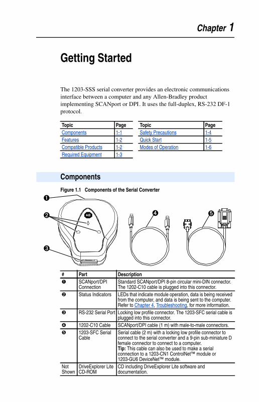
Getting Started
The 1203-SSS serial converter provides an electronic communicationsinterface between a computer and any Allen-Bradley productimplementing SCANport or DPI. It uses the full-duplex, RS-232 DF-1protocol.
Figure 1.1 Components of the Serial Converter
Topic Page Topic PageComponents 1-1 Safety Precautions 1-4Features 1-2 Quick Start 1-5Compatible Products 1-2 Modes of Operation 1-6Required Equipment 1-3
Components
AB
�
��
�
�
# Part Description� SCANport/DPI
ConnectionStandard SCANport/DPI 8-pin circular mini-DIN connector.The 1202-C10 cable is plugged into this connector.
� Status Indicators LEDs that indicate module operation, data is being receivedfrom the computer, and data is being sent to the computer.Refer to Chapter 4, Troubleshooting, for more information.
� RS-232 Serial Port Locking low profile connector. The 1203-SFC serial cable isplugged into this connector.
� 1202-C10 Cable SCANport/DPI cable (1 m) with male-to-male connectors.� 1203-SFC Serial
CableSerial cable (2 m) with a locking low profile connector toconnect to the serial converter and a 9-pin sub-miniature Dfemale connector to connect to a computer.Tip: This cable can also be used to make a serialconnection to a 1203-CN1 ControlNet™ module or1203-GU6 DeviceNet™ module.
NotShown
DriveExplorer LiteCD-ROM
CD including DriveExplorer Lite software anddocumentation.

1-2 Getting Started
Features of the serial converter include the following:
• Three status indicators (LEDs) report the operating status of themodule.
• Serial baud rates of 9600 bps, 19.2Kbps, and 38.4Kbps aresupported. 9600 bps is the factory default.
• The serial converter can connect to products implementingSCANport such as 1336 PLUS II drives, or products implementingDPI such as PowerFlex drives. When used with a product, the serialconverter will autobaud to the SCANport or DPI data rate that isused by the product.
• The serial converter receives power from the connection to theproduct. An outside power source is not needed.
• DriveExplorer (DPI products require version 2.01 or higher),DriveTools 2000 (version 1.xx or higher), or terminal emulationsoftware can be used to configure a serial converter. In addition, aPowerFlex HIM can be used to configure a serial converter that isconnected to a PowerFlex drive or other DPI product.
The serial converter can be used with Allen-Bradley products thatimplement SCANport or DPI.
SCANport products include the following:
DPI products include the following:
Features
Compatible Products
Product Product1305 AC Drive (Drive firmware 2.01 or later) 1394 Motion System1336 FORCE™ Drive 1397 DC Drive1336 IMPACT™ Drive 1557 Medium Voltage Drive1336 PLUS Drive 2364 Regenerative DC Bus Supply Unit1336 PLUS II Drive SMC Dialog Plus™1336 REGEN Line Regeneration Package SMP-3 Smart Motor Protector1336 SPIDER Drive
Product ProductPowerFlex 70 Drive PowerFlex 7000 DrivePowerFlex 700 Drive

Getting Started 1-3
Equipment Shipped with the Serial Converter
When you unpack the serial converter, verify that the package includes:
User-Supplied Equipment
To configure the serial converter, you must use one of the following:
Required Equipment
❑ One Smart Self-powered Serial converter❑ One 1203-SFC serial cable❑ One 1202-C10 cable❑ One DriveExplorer Lite CD❑ This manual
❑ DriveExplorer softwareDPI products require DriveExplorer version 2.01 or greater.SCANport products work with all versions of DriveExplorer.
❑ DriveTools 2000 software (version 1.xx or greater).❑ PowerFlex HIM (only if using a PowerFlex drive or other DPI
product).❑ Terminal emulation software such as HyperTerminal.❑ VT-100 compatible terminal.
1-4 Getting Started
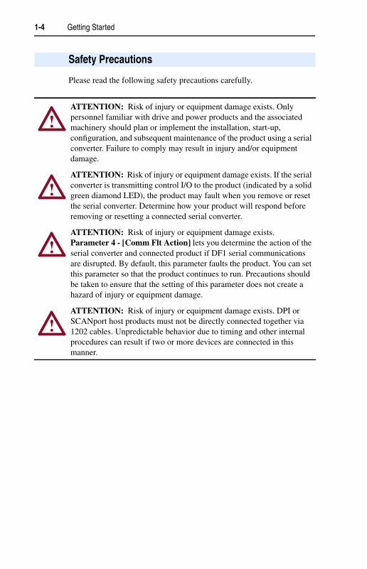
Please read the following safety precautions carefully.
Safety Precautions
!ATTENTION: Risk of injury or equipment damage exists. Onlypersonnel familiar with drive and power products and the associatedmachinery should plan or implement the installation, start-up,configuration, and subsequent maintenance of the product using a serialconverter. Failure to comply may result in injury and/or equipmentdamage.
!ATTENTION: Risk of injury or equipment damage exists. If the serialconverter is transmitting control I/O to the product (indicated by a solidgreen diamond LED), the product may fault when you remove or resetthe serial converter. Determine how your product will respond beforeremoving or resetting a connected serial converter.
!ATTENTION: Risk of injury or equipment damage exists.Parameter 4 - [Comm Flt Action] lets you determine the action of theserial converter and connected product if DF1 serial communicationsare disrupted. By default, this parameter faults the product. You can setthis parameter so that the product continues to run. Precautions shouldbe taken to ensure that the setting of this parameter does not create ahazard of injury or equipment damage.
!ATTENTION: Risk of injury or equipment damage exists. DPI orSCANport host products must not be directly connected together via1202 cables. Unpredictable behavior due to timing and other internalprocedures can result if two or more devices are connected in thismanner.
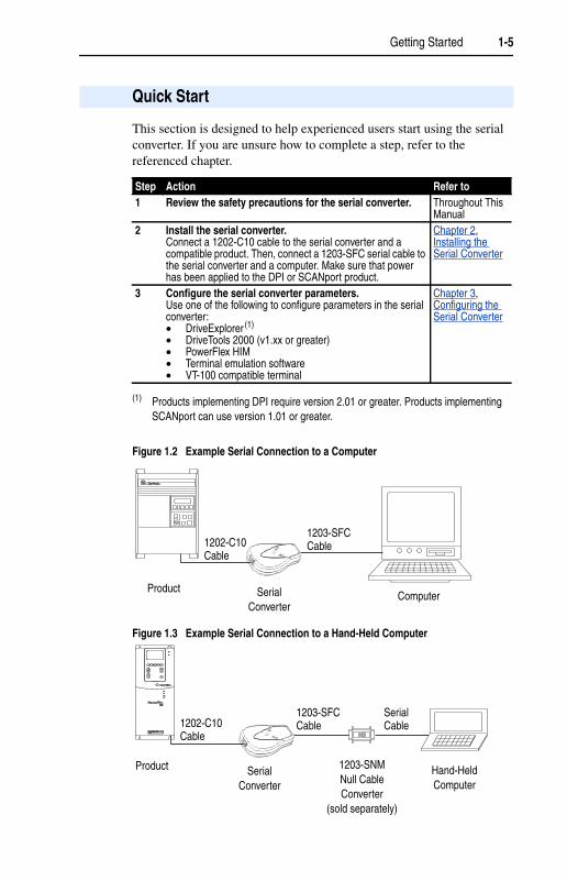
Getting Started 1-5
This section is designed to help experienced users start using the serialconverter. If you are unsure how to complete a step, refer to thereferenced chapter.
Figure 1.2 Example Serial Connection to a Computer
Figure 1.3 Example Serial Connection to a Hand-Held Computer
Quick Start
Step Action Refer to1 Review the safety precautions for the serial converter. Throughout This
Manual2 Install the serial converter.
Connect a 1202-C10 cable to the serial converter and acompatible product. Then, connect a 1203-SFC serial cable tothe serial converter and a computer. Make sure that powerhas been applied to the DPI or SCANport product.
Chapter 2,Installing theSerial Converter
3 Configure the serial converter parameters.Use one of the following to configure parameters in the serialconverter:• DriveExplorer (1)
• DriveTools 2000 (v1.xx or greater)• PowerFlex HIM• Terminal emulation software• VT-100 compatible terminal
(1) Products implementing DPI require version 2.01 or greater. Products implementingSCANport can use version 1.01 or greater.
Chapter 3,Configuring theSerial Converter
Product SerialConverter
Computer
1202-C10Cable
1203-SFCCable
PWR
STS
PORT
MOD
NET A
NET B
Product SerialConverter
1203-SNMNull CableConverter
(sold separately)
Hand-HeldComputer
1202-C10Cable
1203-SFCCable
SerialCable

1-6 Getting Started
Figure 1.4 Status Indicators on the Serial Converter
The serial converter reports its status using status indicators (Figure 1.4).The following table describes the state of the status indicators undernormal operation:
If the diamond status indicator is red, there is a problem. Refer toChapter 4, Troubleshooting.
Modes of Operation
# Status Indicator State Description� Diamond Flashing Green Serial converter is connected to a product
implementing SCANport or DPI.Solid Green Serial converter is or was receiving I/O.
Removing or resetting the serial convertermay cause a serial fault in the product. OnDPI based products a “Soft Logout” can beperformed allowing removal of the converterwithout a fault occurring.
Tip: To remove the adapter without faultingthe drive, set the logic mask in the drive toignore the adapter and then verify that thedrive is receiving its Logic Command andReference from another source.
Off No power or Flash operation in progress.� TX Off Not transmitting data.
Flashing Green Transmitting data.� RX Off Not receiving data.
Flashing Green Receiving data.
AB
���
Chapter 2
Installing the Serial Converter
Chapter 2 provides instructions for installing and removing the serialconverter.
The following cables are all you should need to connect the serialconverter to a product and computer.
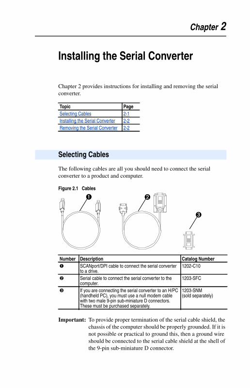
Figure 2.1 Cables
Important: To provide proper termination of the serial cable shield, thechassis of the computer should be properly grounded. If it isnot possible or practical to ground this, then a ground wireshould be connected to the serial cable shield at the shell ofthe 9-pin sub-miniature D connector.
Topic PageSelecting Cables 2-1Installing the Serial Converter 2-2Removing the Serial Converter 2-2
Selecting Cables
Number Description Catalog Number� SCANport/DPI cable to connect the serial converter
to a drive.1202-C10
� Serial cable to connect the serial converter to thecomputer.
1203-SFC
� If you are connecting the serial converter to an H/PC(handheld PC), you must use a null modem cablewith two male 9-pin sub-miniature D connectors.These must be purchased separately.
1203-SNM(sold separately)
� �
�
2-2 Installing the Serial Converter
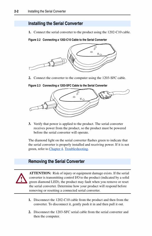
1. Connect the serial converter to the product using the 1202-C10 cable.
Figure 2.2 Connecting a 1202-C10 Cable to the Serial Converter
2. Connect the converter to the computer using the 1203-SFC cable.
Figure 2.3 Connecting a 1203-SFC Cable to the Serial Converter
3. Verify that power is applied to the product. The serial converterreceives power from the product, so the product must be poweredbefore the serial converter will operate.
The diamond light on the serial converter flashes green to indicate thatthe serial converter is properly installed and receiving power. If it is notgreen, refer to Chapter 4, Troubleshooting.
1. Disconnect the 1202-C10 cable from the product and then from theconverter. To disconnect it, gently push it in and then pull it out.
2. Disconnect the 1203-SFC serial cable from the serial converter andthen the computer.
Installing the Serial Converter
RX
TX
RX
TX
Removing the Serial Converter
!ATTENTION: Risk of injury or equipment damage exists. If the serialconverter is transmitting control I/O to the product (indicated by a solidgreen diamond LED), the product may fault when you remove or resetthe serial converter. Determine how your product will respond beforeremoving or resetting a connected serial converter.

Chapter 3
Configuring the Serial Converter
Chapter 3 provides information about configuring the serial converter.
For a list of parameters, refer to Appendix B, Serial ConverterParameters. For definitions of terms in this chapter, refer to the Glossary.
The serial converter stores parameters and other information in its ownNon-Volatile Storage (NVS). You must, therefore, access the serialconverter to view and edit its parameters. The following table lists toolsthat you can use to access the serial converter and edit its parameters.
Topic PageConfiguration Tools 3-1Using the PowerFlex HIM 3-2Using DriveExplorer 3-3Using Terminal Emulation Software 3-4Setting the Serial Port Rate 3-8Setting the Fault Action 3-9Resetting the Serial Converter 3-10
Configuration Tools
Tool Refer ToDriveExplorer software(1)
(1) Products implementing DPI require version 2.01 or greater. Products implementingSCANport can use version 1.01 or greater.
page 3-3 in this manualDriveTools 2000 software (version 1.xx or greater) Documentation for the softwarePowerFlex HIM page 3-2 in this manualTerminal emulation software page 3-4 in this manualVT100-compatible terminal Documentation for the terminal

3-2 Configuring the Serial Converter
If you connect to a PowerFlex drive and it has either an LED or LCDHIM (Human Interface Module), you can use the HIM to access and editparameters in the serial converter as shown below. It is recommendedthat you read through the steps for your HIM before performing thesequence. For additional HIM information, refer to your PowerFlexDrive User Manual or the HIM Quick Reference card.
LED HIM Quick Start
LCD HIM Quick Start
Using the PowerFlex HIM
Step Key(s) Example Screens1. Press ALT and then Sel (Device)
to display the Device Screen.
2. Press the Up Arrow or DownArrow to scroll to the serialconverter. Letters represent filesin the drive, and numbersrepresent ports. The converter isusually connected to port 2 (theexternal port) and sometimes toport 3 (available with a splitter).
3. Press the Enter key to enter yourselection. A parameter databaseis constructed, and then the firstparameter is displayed.
4. Edit the parameters using thesame techniques that you use toedit drive parameters.
Step Key(s) Example Screens1. In the main menu, press the Up
Arrow or Down Arrow to scroll toDevice Select.
2. Press Enter to enter yourselection.
3. Press the Up Arrow or DownArrow to scroll to 1203-SSS.
4. Press Enter to select the serialconverter. A parameter databaseis constructed, and then a menufor the serial converter isdisplayed.
5. Edit the parameters using thesame techniques that you use toedit drive parameters.
OR
ALT Sel
Device
ParameterNumber
Port Number
OR
OR
F-> Stopped M
0.00 Hz
Main Menu:DiagnosticsParameterDevice Select
Port 2 Device
1203-SSS
Main Menu:DiagnosticsParameterDevice Select
Configuring the Serial Converter 3-3
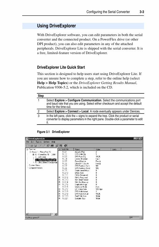
With DriveExplorer software, you can edit parameters in both the serialconverter and the connected product. On a PowerFlex drive (or otherDPI product), you can also edit parameters in any of the attachedperipherals. DriveExplorer Lite is shipped with the serial converter. It isa free, limited-feature version of DriveExplorer.
DriveExplorer Lite Quick Start
This section is designed to help users start using DriveExplorer Lite. Ifyou are unsure how to complete a step, refer to the online help (selectHelp > Help Topics) or the DriveExplorer Getting Results Manual,Publication 9306-5.2, which is included on the CD.
Figure 3.1 DriveExplorer
Using DriveExplorer
Step1 Select Explore > Configure Communication. Select the communications port
and baud rate that you are using. Select either checksum and accept the defaulttime for the time-out.
2 Select Explore > Connect > Local. A node eventually appears under Devices.3 In the left pane, click the + signs to expand the tree. Click the product or serial
converter to display parameters in the right pane. Double-click a parameter to editit.
3-4 Configuring the Serial Converter
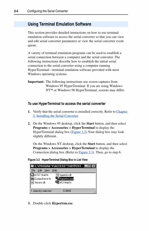
This section provides detailed instructions on how to use terminalemulation software to access the serial converter so that you can viewand edit serial converter parameters or view the serial converter eventqueue.
A variety of terminal emulation programs can be used to establish aserial connection between a computer and the serial converter. Thefollowing instructions describe how to establish the initial serialconnection to the serial converter using a computer runningHyperTerminal—terminal emulation software provided with mostWindows operating systems.
Important: The following instructions use screen captures fromWindows 95 HyperTerminal. If you are using WindowsNT™ or Windows 98 HyperTerminal, screens may differ.
To use HyperTerminal to access the serial converter
1. Verify that the serial converter is installed correctly. Refer to Chapter2, Installing the Serial Converter.
2. On the Windows 95 desktop, click the Start button, and then selectPrograms > Accessories > HyperTerminal to display theHyperTerminal dialog box (Figure 3.2).Your dialog box may lookslightly different.
On the Windows NT desktop, click the Start button, and then selectPrograms > Accessories > HyperTerminal to display theConnection dialog box (Refer to Figure 3.3). Then, go to step 6.
Figure 3.2 HyperTerminal Dialog Box in List View
3. Double-click Hypertrm.exe.
Using Terminal Emulation Software

Configuring the Serial Converter 3-5
The Connection Description dialog box appears in the HyperTerminalworkspace.
Figure 3.3 Connection Dialog Box
4. In the Name box, type any name (for example, converter), and thenselect any icon in the Icon box.
5. Click OK to display the Phone Number dialog box.
6. In the Connect Using box, select the communications port that youintend to use (usually COM1 or COM2).
7. Click OK to display the Properties dialog box.

3-6 Configuring the Serial Converter
8. Select the settings shown in Figure 3.4.
Important: If you have previously set Parameter 03 - [DF1 RateCfg] to 19.2K or 38.4K, select that value in the Bits persecond box.
Figure 3.4 Properties Dialog Box
9. Click OK. A blank HyperTerminal workspace appears.
10. Select File > Properties to display the Properties dialog box.
11. Click the Settings tab. See Figure 3.5.
12. Under Function, arrow, and ctrl keys act as, select Terminal keys.
13. In the Emulation box, select VT100.

Configuring the Serial Converter 3-7
Figure 3.5 Properties Dialog Box
14. Click OK to display the HyperTerminal workspace.
15. Press the Enter key until the main menu appears.
Figure 3.6 Main Menu
If no text or meaningless text appears instead of the Main Menu, adjustthe baud rate in your software. Refer to Troubleshooting PotentialProblems in Chapter 4 for detailed instructions.
TIP: Select File > Save to save the HyperTerminal configuration thatyou just created. In future connections, you can select the savedconfiguration and quickly connect to the serial converter.
What do you want to do? PageEdit the serial port rate, or fault action 3-8 through 3-10View the event queue 4-3View DF1 data 4-6Update the firmware C-1
Main Menu - Enter Number for Selection1> Display Setup Parameters2> Display Event Queue3> Flash Upgrade
3-8 Configuring the Serial Converter
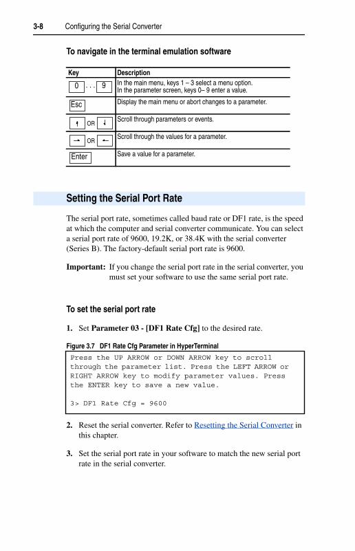
To navigate in the terminal emulation software
The serial port rate, sometimes called baud rate or DF1 rate, is the speedat which the computer and serial converter communicate. You can selecta serial port rate of 9600, 19.2K, or 38.4K with the serial converter(Series B). The factory-default serial port rate is 9600.
Important: If you change the serial port rate in the serial converter, youmust set your software to use the same serial port rate.
To set the serial port rate
1. Set Parameter 03 - [DF1 Rate Cfg] to the desired rate.
Figure 3.7 DF1 Rate Cfg Parameter in HyperTerminal
2. Reset the serial converter. Refer to Resetting the Serial Converter inthis chapter.
3. Set the serial port rate in your software to match the new serial portrate in the serial converter.
Key DescriptionIn the main menu, keys 1 – 3 select a menu option.In the parameter screen, keys 0– 9 enter a value.
Display the main menu or abort changes to a parameter.
Scroll through parameters or events.
Scroll through the values for a parameter.
Save a value for a parameter.
0 9. . .
Esc
OR
OR
Enter
Setting the Serial Port Rate
Press the UP ARROW or DOWN ARROW key to scrollthrough the parameter list. Press the LEFT ARROW orRIGHT ARROW key to modify parameter values. Pressthe ENTER key to save a new value.
3> DF1 Rate Cfg = 9600

Configuring the Serial Converter 3-9
By default, when DF1 serial communications are disrupted (e.g., a serialcable is disconnected) and control I/O is being transmitted, the serialconverter and connected product respond by faulting. You can set thefollowing actions:
To change the fault action• Set the value of Parameter 04 - [Comm Flt Action] to the desired
fault action.
Figure 3.8 Comm Flt Action Parameter in HyperTerminal
Changes to this parameter take effect immediately. A reset is notrequired.
Setting the Fault Action
Action DescriptionFault The product will fault.Stop The product will stop and not fault (DPI host products only).Zero data The product is sent 0 for output data after a communications disruption.
This does not command a stop.Hold last The product continues in its present state after a communications
disruption.
!ATTENTION: Risk of injury or equipment damage exists.Parameter 04 - [Comm Flt Action] lets you determine the action ofthe serial converter and connected product if communications aredisrupted. By default, this parameter faults the product. You can set thisparameter so that the product continues to run. Precautions should betaken to ensure that the setting of this parameter does not create ahazard of injury or equipment damage.
Press the UP ARROW or DOWN ARROW key to scrollthrough the parameter list. Press the LEFT ARROW orRIGHT ARROW key to modify parameter values. Pressthe ENTER key to save a new value.
4> Comm Flt Action = Fault

3-10 Configuring the Serial Converter
After you change some parameters, you must reset the serial converterfor the new setting to take effect. You can reset it by removing and thenreapplying power or by using Parameter 05 - [Reset Module].
To reset the serial converter• Set Parameter 05 - [Reset Module] to either Reset Module or Set
Defaults. “Reset Module” will reset the serial converter. “SetDefaults” will set all parameters in the serial converter to theirfactory-default values.
Figure 3.9 Reset Module Parameter in HyperTerminal
After you enter the “Reset Module” value, the serial converter will bereset. This parameter will then be reset to “Ready.”
Resetting the Serial Converter
!ATTENTION: Risk of injury or equipment damage exists. If the serialconverter is transmitting control I/O to the product (indicated by a solidgreen diamond LED), the product may fault when you remove or resetthe serial converter. Determine how your product will respond beforeremoving or resetting a connected serial converter.
Press the UP ARROW or DOWN ARROW key to scrollthrough the parameter list. Press the LEFT ARROW orRIGHT ARROW key to modify parameter values. Pressthe ENTER key to save a new value.
5> Reset Module = Reset Module

Chapter 4
Troubleshooting
Chapter 4 provides information to troubleshoot the serial converter.
The serial converter reports its status using status indicators. See Figure4.1.
Figure 4.1 Status Indicators on the Serial Converter
Topic PageUnderstanding the Status Indicators 4-1Module Diagnostic Items 4-3Viewing and Clearing the Event Queue 4-3Viewing and Clearing DF1 Communication Statistics 4-6Troubleshooting Potential Problems 4-7
Understanding the Status Indicators
# Status Indicator Description Refer To� Diamond Serial converter status Diamond Status Indicator
on page 4-2� TX Serial converter is transmitting
dataTX Status Indicator onpage 4-2
� RX Serial converter is receivingdata
RX Status Indicator onpage 4-2
AB
���
4-2 Troubleshooting
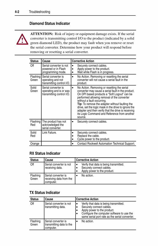
Diamond Status Indicator
RX Status Indicator
TX Status Indicator
!ATTENTION: Risk of injury or equipment damage exists. If the serialconverter is transmitting control I/O to the product (indicated by a solidgreen diamond LED), the product may fault when you remove or resetthe serial converter. Determine how your product will respond beforeremoving or resetting a serial converter.
Status Cause Corrective ActionOff Serial converter is not
powered or in Flashprogramming mode.
• Securely connect cables.• Apply power to the product.• Wait while Flash is in progress.
FlashingGreen
Serial converter isoperating and nottransmitting control I/O.
• No Action. Removing or resetting the serialconverter will not cause a serial fault in theproduct.
SolidGreen
Serial converter isoperating and is or wastransmitting control I/O.
• No Action. Removing or resetting the serialconverter may cause a serial fault in the product.On DPI based products a “Soft Logout” can beperformed allowing removal of the converterwithout a fault occurring.Tip: To remove the adapter without faulting thedrive, set the logic mask in the drive to ignore theadapter and then verify that the drive is receivingits Logic Command and Reference from anothersource.
FlashingRed
The product has notacknowledged theserial converter.
• Securely connect cables.
SolidRed
Link Failure. • Securely connect cables.• Replace the cable.• Cycle power to the product.
Orange • Contact Rockwell Automation Technical Support.
Status Cause Corrective ActionOff Serial converter is not
receiving data.• Verify that data is being transmitted.• Securely connect cables.• Apply power to the product.
FlashingGreen
Serial converter isreceiving data from thecomputer.
• No action.
Status Cause Corrective ActionOff Serial converter is not
transmitting data.• Verify that data is being transmitted.• Securely connect cables.• Apply power to the product.• Configure the computer software to use the
same serial port rate as the serial converter.FlashingGreen
Serial converter istransmitting data to thecomputer.
• No action.

Troubleshooting 4-3
The following diagnostic items can be accessed using DriveExplorer(version 2.01 or higher).
It is normal for the event queue in the serial converter to contain events.If you encounter unexpected communication problems, you can accessthe event queue and view the most recent events.
To view the event queue
1. Access the event queue using a configuration tool. Refer toConfiguration Tools in Chapter 3.
2. Scroll through events in the event queue. The most recent event canbe found at 2R > Event Queue 1.
Module Diagnostic Items
No. Name Description1 Common Logic
CmdCurrent value of the Common Logic Command being transmittedto the host by this peripheral.
2 Prod Logic Cmd Current value of the Product Specific Logic Command beingtransmitted to the host by this peripheral.
3 Reference Current value of the Product Specific Reference beingtransmitted to the host by this peripheral.
4 Common LogicSts
Current value of the Common Logic Status being received fromthe host by this peripheral.
5 Prod Logic Sts Current value of the Product Specific Logic Status being receivedfrom the host by this peripheral.
6 Feedback Current value of the Product Specific Feedback being receivedfrom the host by this peripheral.
7 DPI Rx Err Cntr Current value of the DPI CAN Receive Error Counter register.8 DPI Rx Err Max Maximum value of the DPI CAN Receive Error Counter register.9 DPI Tx Err Cntr Current value of the DPI CAN Transmit Error Counter register.10 DPI Tx Err Max Maximum value of the DPI CAN Transmit Error Counter register.11 Field Flash Cntr Current value of the Field Flash Counter.12 CPU CPU Type.
Viewing and Clearing the Event Queue
4-4 Troubleshooting
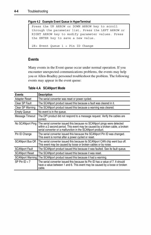
Figure 4.2 Example Event Queue in HyperTerminal
Events
Many events in the Event queue occur under normal operation. If youencounter unexpected communications problems, the events may helpyou or Allen-Bradley personnel troubleshoot the problem. The followingevents may appear in the event queue:
Table 4.A SCANport Mode
Press the UP ARROW or DOWN ARROW key to scrollthrough the parameter list. Press the LEFT ARROW orRIGHT ARROW key to modify parameter values. Pressthe ENTER key to save a new value.
2R> Event Queue 1 = Pin ID Change
Events DescriptionAdapter Reset The serial converter was reset or power cycled.Clear SP Fault The SCANport product issued this because a fault was cleared in it.Clear SP Warning The SCANport product issued this because a warning was cleared.Empty Queue No event is in the queue.Message Timeout The DPI product did not respond to a message request. Verify the cables are
correct.No SCANport Ping The serial converter issued this because no SCANport pings were detected
within a 2 second period. This event may be caused by a broken cable, a brokenserial converter or a malfunction in the SCANport product.
Pin ID Change The serial converter issued this because the SCANport Pin ID was changed.This event is normal after a power cycled or reset.
SCANport Bus Off The serial converter issued this because its SCANport CAN chip went bus off.This event may be caused by loose or broken cables or by noise.
SCANport Fault The SCANport product issued this because it was faulted. See its fault queue.SCANport Reset The SCANport product issued this because it was reset.SCANport Warning The SCANport product issued this because it had a warning.SP Pin ID = 7 The serial converter issued this because its Pin ID has a value of 7. It should
have a value between 1 and 6. This event may be caused by a loose or brokencable.

Troubleshooting 4-5
Table 4.B DPI Mode
To clear the event queue
1. Access the event queue using a configuration tool. Refer toConfiguration Tools in Chapter 3.
2. Set the value of 1 > Clr Event Queue to Enable, and then pressEnter to clear the event queue.
Figure 4.3 Reset Event Queue in HyperTerminal
Events DescriptionBad Host Flt The serial converter was connected to an incompatible product.Control Disabled The serial converter has sent a “Soft Control Disable” command to the DPI
product.Control Enabled The serial converter has sent a “Soft Control Enable” command to the DPI
product.DPI Bus Off Flt A bus-off condition was detected on DPI. This event may be caused by loose or
broken cables or by noise.DPI Fault Clear A DPI product has issued a fault clear message.DPI Fault Msg The drive entered a faulted state.Dup. Port Flt Another peripheral with the same port number is already in use.EEPROM Sum Flt The EEPROM in the serial converter is corrupt.Host Sent Reset The DPI product issued this because it was reset.Message Timeout The DPI product did not respond to a message request. Verify the cables are
correct.No Event Empty event queue entry.Normal Startup Adapter initially powered up or was reset.Online @ 125kbps The serial converter and DPI product are communicating at 125kbps.Online @ 500kbps The serial converter and DPI product are communicating at 500kbps.PCCC I/O Time Flt The serial converter has not received a PCCC Control message for longer than
the specified PCCC Control Time-out.Ping in Message An unexpected ping was received.Ping Time Flt A ping message was not received on DPI within the specified time.Port Change Flt The DPI port changed.Port ID Flt The serial converter is not connected to a correct port on a DPI product.Type 0 Login The serial converter has logged in for type 0 control.Type 0 Time Flt The serial converter has not received a type 0 status message within the
specified time.Use I/O Sent The serial converter has begun sending product specific control information.
Press the UP ARROW or DOWN ARROW key to scrollthrough the parameter list. Press the LEFT ARROW orRIGHT ARROW key to modify parameter values. Pressthe ENTER key to save a new value.
1> Clr Event Queue = Enable

4-6 Troubleshooting
If you encounter unexpected communications problems or are creatingan application that uses DF1 data, you can view the communicationsstatistics in the serial converter. Parameters 06 through 15 store this data.
In order to view and clear DF1 data, you must access the main menu inthe serial converter firmware. Refer to Configuration Tools in Chapter 3.
To view DF1 data
1. Access the parameters in the serial converter using a configurationtool. Refer to Configuration Tools in Chapter 3.
2. Scroll through the DF1 parameters. Parameters 06 through 15contain DF1 data. For a description of each parameter, refer toAppendix B, Serial Converter Parameters.
Figure 4.4 Example Parameter Display in HyperTerminal
To clear DF1 data
1. Access the parameters in the serial converter using a configurationtool. Refer to Configuration Tools in Chapter 3.
2. Set the value of Parameter 6 - [Clear DF1 Counts] to ClearCounts, and then press Enter to clear the DF1 data.
Figure 4.5 Example Parameter Display in HyperTerminal
Viewing and Clearing DF1 Communication Statistics
Press the UP ARROW or DOWN ARROW key to scrollthrough the parameter list. Press the LEFT ARROW orRIGHT ARROW key to modify parameter values. Pressthe ENTER key to save a new value.
7R> DF1 Packets Sent = 0
Press the UP ARROW or DOWN ARROW key to scrollthrough the parameter list. Press the LEFT ARROW orRIGHT ARROW key to modify parameter values. Pressthe ENTER key to save a new value.
6> Clear DF1 Counts = Clear Counts

Troubleshooting 4-7
Troubleshooting Potential Problems
Description ActionYou are unable to establish aconnection between your computerand the serial converter.
• If the status indicators are off, connect thecables and apply power to the product.
• Configure your software and serial converterto use the same serial port rate (baud rate).
After changing the serial port rate,you are no longer able tocommunicate with the serialconverter and connected product.For example, in HyperTerminal,meaningless text appears on thescreen when you press Enter. InDriveExplorer, parameter values arenot updated.
Reset the serial port rate in the software.Instructions are included here for resetting theserial port rate in HyperTerminal andDriveExplorer. If you are using a differentconfiguration tool, refer to its user manual.HyperTerminal1. Select File > Properties, and then click
Configure.2. Select the new baud rate, and then click OK.3. Save and close HyperTerminal.4. Double-click on your HyperTerminal file (*.ht)
to restart HyperTerminal.5. Press Enter until the main menu appears.DriveExplorer1. Select Explore > Configure
Communication.2. Select the new baud rate. DriveExplorer
should start updating values again. If it doesnot, restart DriveExplorer.
You set a new serial port rate, but theserial converter is still using the oldserial port rate.
• Reset the adapter. Refer to Chapter 3,Configuring the Serial Converter.
You are using either DriveExplorerv1.xx or DriveTools32 v2.xx and youcan not perform any of the following:1. Route out over a network, such
as DeviceNet to another drive.2. Access DPI peripherals such as
the 20-COMM-D DeviceNetadapter.
3. Access 32-bit data.
Normal operation. These features require either:• DriveExplorer v2.xx or greater.• DriveTools 2000 v1.xx or greater.
You are using either DriveExplorerv2.xx (or greater) or DriveTools 2000v1.xx (or greater) and you can notperform any of the following:1. Route out over a network, such
as DeviceNet to another drive.2. Access DPI peripherals such as
the 20-COMM-D DeviceNetadapter.
3. Access 32-bit data.
• Check the 1203-SSS firmware version – youmust have FRN 3.xxx or greater.
• Parameter 16 - [Interface Select] must be setto “Auto.”
• Reset the converter. See Resetting the SerialConverter in Chapter 3.

4-8 Troubleshooting
Notes:

Appendix A
Specifications
Appendix A provides the specifications for the serial converter.
Topic Page Topic PageCommunications A-1 Environmental A-2Electrical A-1 Regulatory Compliance A-2Mechanical A-1
Communications
NetworkProtocolPort RateData BitsParityStop BitsFlow ControlError
RS-232 Serial DF1, Full Duplex9600, 19.2K, or 38.4K8None1NoneCRC or BCC (Auto-Detected)
ProductProtocolData Rates
SCANport: 125KDPI: 125K/500K
Electrical
Consumption 130mA at +12V DCThe serial converter draws the required powerfrom the connected product. An external powersource is not required.
Mechanical
Dimensions 103.5 x 73.4 x 23.6 mm (4.08 x 2.89 x 0.93 in.)Weight 70.88 g (2.5 oz.)

A-2 Specifications
Environmental
TemperatureOperatingStorage
0 to +50°C (32 to 122°F)-40 to +85°C (-40 to 185°F)
Relative Humidity 5 to 95% non-condensingVibration
OperatingNon-Operating
2.5G @5Hz-2KHz5 G @5Hz-2KHz
ShockOperatingNon-Operating
30 G peak acceleration, 11(+/-1)ms pulse width50 G peak acceleration, 11(+/-1)ms pulse width
Regulatory Compliance
ULCE
508C and CUL

Appendix B
Serial Converter Parameters
This chapter presents information about the parameters in the serialconverter.
Parameter List
No. Name and Description Details01 [Adapter Port]
Port on the host product to which the serial converter isconnected.
Default: 0Minimum: 0Maximum: 7Type: Read Only
02 [DF1 Addr Cfg]DF1 node address for the serial converter. This is adecimal value.
Default: 1Minimum: 0Maximum: 254Type: Read/WriteReset Required: Yes
03 [DF1 Rate Cfg]Serial port rate for the DF1 serial port on the serialconverter.
Default: 0 = 9600Values: 0 = 9600
1 = 19.2K2 = 38.4K
Type: Read/WriteReset Required: Yes
04 [Comm Flt Action]Action that the serial converter and product take if theserial converter detects that DF1 serialcommunications are disrupted. This setting is effectiveonly if control I/O is transmitted through the serialconverter.
Default: 0 = FaultValues: 0 = Fault
1 = Stop (DPI) orFault (SCANport)2 = Zero Data3 = Hold Last
Type: Read/WriteReset Required: No
!ATTENTION: Risk of injury or equipment damage exists. Parameter 04 -[Comm Flt Action] lets you determine the action of the serial converter andconnected product if communications are disrupted. By default, thisparameter faults the product. You can set this parameter so that the productcontinues to run. Precautions should be taken to ensure that the setting ofthis parameter does not create a hazard of injury or equipment damage.
B-2 Serial Converter Parameters
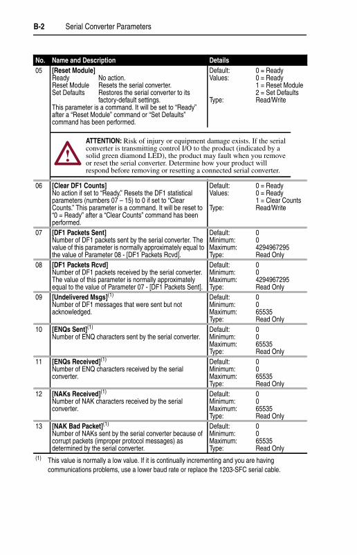
No. Name and Description Details05 [Reset Module]
Ready No action.Reset Module Resets the serial converter.Set Defaults Restores the serial converter to its
factory-default settings.This parameter is a command. It will be set to “Ready”after a “Reset Module” command or “Set Defaults”command has been performed.
Default: 0 = ReadyValues: 0 = Ready
1 = Reset Module2 = Set Defaults
Type: Read/Write
06 [Clear DF1 Counts]No action if set to “Ready.” Resets the DF1 statisticalparameters (numbers 07 – 15) to 0 if set to “ClearCounts.” This parameter is a command. It will be reset to“0 = Ready” after a “Clear Counts” command has beenperformed.
Default: 0 = ReadyValues: 0 = Ready
1 = Clear CountsType: Read/Write
07 [DF1 Packets Sent]Number of DF1 packets sent by the serial converter. Thevalue of this parameter is normally approximately equal tothe value of Parameter 08 - [DF1 Packets Rcvd].
Default: 0Minimum: 0Maximum: 4294967295Type: Read Only
08 [DF1 Packets Rcvd]Number of DF1 packets received by the serial converter.The value of this parameter is normally approximatelyequal to the value of Parameter 07 - [DF1 Packets Sent].
Default: 0Minimum: 0Maximum: 4294967295Type: Read Only
09 [Undelivered Msgs](1)
Number of DF1 messages that were sent but notacknowledged.
Default: 0Minimum: 0Maximum: 65535Type: Read Only
10 [ENQs Sent](1)
Number of ENQ characters sent by the serial converter.Default: 0Minimum: 0Maximum: 65535Type: Read Only
11 [ENQs Received](1)
Number of ENQ characters received by the serialconverter.
Default: 0Minimum: 0Maximum: 65535Type: Read Only
12 [NAKs Received](1)
Number of NAK characters received by the serialconverter.
Default: 0Minimum: 0Maximum: 65535Type: Read Only
13 [NAK Bad Packet](1)
Number of NAKs sent by the serial converter because ofcorrupt packets (improper protocol messages) asdetermined by the serial converter.
Default: 0Minimum: 0Maximum: 65535Type: Read Only
(1) This value is normally a low value. If it is continually incrementing and you are havingcommunications problems, use a lower baud rate or replace the 1203-SFC serial cable.
!ATTENTION: Risk of injury or equipment damage exists. If the serialconverter is transmitting control I/O to the product (indicated by asolid green diamond LED), the product may fault when you removeor reset the serial converter. Determine how your product willrespond before removing or resetting a connected serial converter.

Serial Converter Parameters B-3
No. Name and Description Details14 [NAK No Memory](1)
Number of NAKs sent by the serial converter because itdid not have sufficient memory to buffer the incomingmessages. The serial converter runs out of memory if acommand has not completed and there is no place tosave the new commands.
Default: 0Minimum: 0Maximum: 65535Type: Read Only
15 [Duplicate Msgs](1)
Number of duplicate messages sent by the serialconverter. This value contains the total number ofconsecutive messages received by this device with thesame TNS (Transaction Sequence) number.
Default: 0Minimum: 0Maximum: 65535Type: Read Only
16 [Interface Select]Auto Converter will automatically run DPI if
connected to a DPI product or SCANport ifconnected to a SCANport product.
SCANport Converter will perform SCANport servicesonly.
Set this parameter to “Auto” (default) unless you are usingDriveExplorer v1.xx or DriveTools32 v2.xx software andyou are connected to a DPI product. Use “SCANport” forthese software versions.
Default: 0 = AutoValues: 0 = Auto
1 = SCANportType: Read/Write
17 [DPI Data Rate](2)
Data rate used by the DPI host product. This data rate isset in the drive, and the adapter autobauds to it.
Default: 0Values: 0 = 125 kbps
1 = 500 kbpsType: Read Only
18 [DF1 Addr Actual](2)
DF1 address actually used by the serial converter.Default: 1Minimum: 0Maximum: 254Type: Read Only
19 [DF1 Rate Actual](2)
Serial port rate actually used for the DF1 serial port on theserial converter.
Default: 0 = 9600Values: 0 = 9600
1 = 19.2K2 = 38.4K
Type: Read Only20 [Ref/Fdbk Size](2)
Size of the Reference/Feedback. The host productdetermines the size of the Reference/Feedback. Theserial converter automatically uses the correct size.
Default: 0 = 16-bitValue: 0 = 16-bit
1 = 32-bitType: Read Only
21 [Datalink Size](2)
Size of each Datalink word. The host product determinesthe size of Datalinks.
Default: 0 = 16-bitValues: 0 = 16-bit
1 = 32-bitType: Read Only
(1) This value is normally a low value. If it is continually incrementing and you are havingcommunications problems, use a lower baud rate or replace the 1203-SFC serial cable.
(2) The parameter appears only when the serial converter is connected to a product implementingDPI.

B-4 Serial Converter Parameters
Notes:

Appendix C
Flash Updates
Appendix C provides information on updating DPI host or peripheral
product firmware.
Please take the following precautions to ensure a successful Flash:
• Obtain the new firmware version from Rockwell Automation. Save itto the hard drive of the computer. Do not attempt to perform a Flashfrom a floppy disk or a network.
• Read all instructions supplied with the new firmware file.
• Use a computer running terminal emulation software that supportsXmodem transfers (e.g., HyperTerminal). In this manual, we showhow to use HyperTerminal.
• Record parameter values in the device that will be flashed. Updatesmay reset parameters to their default settings.
• Ensure that the DPI host product (i.e. PowerFlex 70) is stopped.
• Close all programs except the terminal emulation program that youare using to Flash the serial converter.
• Disable the screen saver and antivirus programs so that they do notstart during the Flash.
• If you are using a laptop computer, turn off the FIFO buffers inHyperTerminal. In HyperTerminal, select File > Properties todisplay the Properties dialog box. Click Configure, and then clickAdvanced. Ensure that a check mark does not appear next to UseFIFO buffers.
• Verify that Parameter 16 - [Interface Select] is set to “Auto”(default).
Topic PagePreparing for a Flash Update C-1Performing a Flash Update withHyperTerminal
C-2
Troubleshooting Potential Flash Problems C-4
Preparing for a Flash Update
C-2 Flash Updates
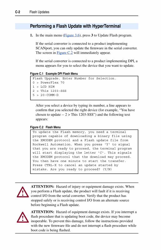
1. In the main menu (Figure 3.6), press 3 to Update Flash program.
If the serial converter is connected to a product implementingSCANport, you can only update the firmware in the serial converter.The screen in Figure C.2 will immediately appear.
If the serial converter is connected to a product implementing DPI, amenu appears for you to select the device that you want to update.
Figure C.1 Example DPI Flash Menu
After you select a device by typing its number, a line appears toconfirm that you selected the right device (for example, “You havechosen to update -- 2 > This 1203-SSS”) and the following textappears:
Figure C.2 Flash Menu
Performing a Flash Update with HyperTerminal
Flash Upgrade. Enter Number for Selection.0 > PowerFlex 701 > LCD HIM2 > This 1203-SSS5 > 20-COMM-D
To update the Flash memory, you need a terminalprogram capable of downloading a binary file usingthe XMODEM protocol and a Flash update file fromRockwell Automation. When you press 'Y' to signalthat you are ready to proceed, the terminal programwill start displaying the letter 'C'. This signalsthe XMODEM protocol that the download may proceed.You then have one minute to start the transfer.Press CTRL-X to cancel an update started bymistake. Are you ready to proceed? (Y/N)
!ATTENTION: Hazard of injury or equipment damage exists. Whenyou perform a Flash update, the product will fault if it is receivingcontrol I/O from the serial converter. Verify that the product hasstopped safely or is receiving control I/O from an alternate sourcebefore beginning a Flash update.
!ATTENTION: Hazard of equipment damage exists. If you interrupt aflash procedure that is updating boot code, the device may becomeinoperable. To prevent this damage, follow the instructions providedwith the new firmware file and do not interrupt a flash procedure whileboot code is being flashed.

Flash Updates C-3
2. If the Flash can be completed safely, type Y. The letter “C”repeatedly appears. It is the Xmodem prompt and continues toappear until you send a binary file.
Important: Press Ctrl + X to cancel a Flash update procedure.
3. Select Transfer > Send File to display the send file dialog box.
4. Click Browse and navigate to the Flash file.
5. Double-click the file. Its name appears in the Filename box.
6. In the Protocol box, select Xmodem.
Figure 4.6 Example Send File Dialog Box
7. Click Send. A dialog box appears and reports the progress of thedownload. When it is complete, the message “Operation Complete”appears.
Important: Keep the device powered for 15 seconds after the operationhas completed.
8. Press the Enter key to return to the main menu.
C-4 Flash Updates
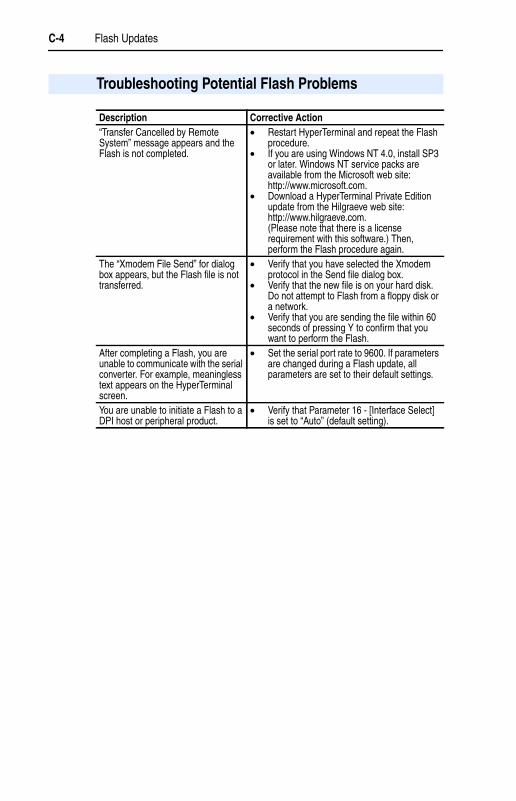
Troubleshooting Potential Flash Problems
Description Corrective Action“Transfer Cancelled by RemoteSystem” message appears and theFlash is not completed.
• Restart HyperTerminal and repeat the Flashprocedure.
• If you are using Windows NT 4.0, install SP3or later. Windows NT service packs areavailable from the Microsoft web site:http://www.microsoft.com.
• Download a HyperTerminal Private Editionupdate from the Hilgraeve web site:http://www.hilgraeve.com.(Please note that there is a licenserequirement with this software.) Then,perform the Flash procedure again.
The “Xmodem File Send” for dialogbox appears, but the Flash file is nottransferred.
• Verify that you have selected the Xmodemprotocol in the Send file dialog box.
• Verify that the new file is on your hard disk.Do not attempt to Flash from a floppy disk ora network.
• Verify that you are sending the file within 60seconds of pressing Y to confirm that youwant to perform the Flash.
After completing a Flash, you areunable to communicate with the serialconverter. For example, meaninglesstext appears on the HyperTerminalscreen.
• Set the serial port rate to 9600. If parametersare changed during a Flash update, allparameters are set to their default settings.
You are unable to initiate a Flash to aDPI host or peripheral product.
• Verify that Parameter 16 - [Interface Select]is set to “Auto” (default setting).

Glossary
A Application Code
Code that runs in the adapter after the boot code calls it. It performs thenormal operations of the system.
B BCC
Block Check Character. An error detection scheme where the 2’scomplement of the 8-bit sum (modulo-256 arithmetic sum) of all databytes in a transmission block. It provides a means of checking theaccuracy of each message transmission.
Boot Code
Code that runs when the adapter first receives power. It checks basicoperations and then calls the application code.
Bus Off
A bus off condition occurs when an abnormal rate of errors is detectedon the Control Area Network (CAN) bus in a device. The bus-off devicecannot receive or transmit messages. This condition is often caused bycorruption of the network data signals due to noise or data ratemismatch.
C CRC
Cyclic redundancy check. An error detection scheme where all of thecharacters in a message are treated as a string of bits representing abinary number. This number is divided by a predetermined binarynumber (a polynomial) and the remainder is appended to the message asa CRC character. A similar operation occurs at the receiving end to provetransmission integrity.
D DF1 Protocol
A peer-to-peer link layer protocol that combines features of ANSIX3.28-1976 specification subcategories D1 (data transparency) and F1(two-way simultaneous transmission with embedded responses).
DF1 Rate
A unit of signaling speed equal to the number of discrete conditions orsignal events per second. It is also called “baud rate” or “serial port rate.”

Glossary-2
DPI
DPI is a second generation peripheral communication interface used byvarious Allen-Bradley drives and power products. It is a functionalenhancement to SCANport.
DPI Peripheral
A device that provides an interface between DPI and a network or user.Peripheral devices are also referred to as “adapters” and “modules.” Theserial converter and PowerFlex HIM are examples of DPI peripherals.
DPI Product
A device that uses the DPI communications interface to communicatewith one or more peripheral devices. For example, a motor drive such asa PowerFlex drive is a DPI product. In this manual, a DPI product is alsoreferred to as “product” or “host.”
DriveExplorer
An easy-to-use software application designed for MicrosoftWindows 95, Windows 98, Windows NT (4.0 or greater), and WindowsCE (2.0 or greater) operating systems. To fully utilize DPI products, useDriveExplorer version 2.xx or greater. SCANport products work with allversions of DriveExplorer. This application is a tool for monitoring andconfiguring Allen-Bradley products and adapters. A free version ofDriveExplorer Lite is included with the serial converter. Informationabout DriveExplorer can be accessed at http://www.ab.com/drives/driveexplorer.
DriveTools
A software suite designed for Microsoft Windows 95, Windows 98, andWindows NT (4.0 or greater) operating systems. To fully utilize DPIproducts, use DriveTools 2000 version 1.xx or greater. SCANportproducts work with all versions of DriveTools32 (or DriveTools 2000).This software suite provides a family of tools that you can use toprogram, monitor, control, troubleshoot, and maintain Allen-Bradleyproducts. Information about DriveTools can be accessed at http://www.ab.com/drives.
F Flash Update
The process of updating firmware in a device.

Glossary-3
H HIM (Human Interface Module)
A device that can be used to configure and control a PowerFlex drive.New HIMs (20-HIM-x) can be used to configure connected peripheralssuch as the serial converter.
Hold Last
When communications are disrupted (e.g., serial cable is disconnected),the converter and product can respond by holding last state. Hold laststate results in the product receiving the last data received via the DF1connection before the disruption. If the product was in RUN mode andusing the Reference from the converter, it will continue to run at thesame Reference.
N Non-Volatile Storage (NVS)
NVS is the permanent memory of a device. Devices such as theconverter store parameters and other information in NVS so that they arenot lost when the device loses power. NVS is sometimes called“EEPROM.”
P PCCC (Programmable Controller Communications Command)
PCCC is the protocol used by some controllers to communicate withdevices on a network. Some software products (for example,DriveExplorer and DriveTools 2000) also use PCCC to communicate.
Ping
A ping is a message that is sent by a DPI product to its peripheraldevices. They use the ping to gather data about the product, includingwhether it can receive messages and whether they can log in for control.
S SCANport
A peripheral communications interface for various Allen-Bradley drivesand power products.
SCANport Peripheral Device
A device that provides an interface between SCANport and a network oruser. Peripheral devices are also referred to as “adapters” and “modules.”The serial converter and HIM are examples of SCANport peripherals.

Glossary-4
SCANport Product
A device that uses the SCANport communications interface tocommunicate with one or more peripheral devices. For example, a motordrive such as a 1336 PLUS II is a SCANport product. In this manual, aSCANport product is also referred to as “product.”
Serial Converter
The serial converter provides an electronic communications interfacebetween any Allen-Bradley SCANport/DPI product and a computer withan RS-232 port. This converter uses a full-duplex RS-232 DF1 protocol.The serial converter may also be referred to as “1203-SSS converter,”“converter,” “DPI peripheral,” or “SCANport peripheral.”
Status Indicators
Status indicators are LEDs that are used to report the status of a device.There are three status indicators on the converter.
T Type 0/Type 1/Type 2 Control
When transmitting I/O, the adapter can use different types of messagesfor control. The Type 0, Type 1, and Type 2 events help Allen-Bradleypersonnel identify the type of messages that an adapter is using.
X Xmodem
Developed by Ward Christensen in 1978, Xmodem is a protocol used totransfer data. You can use the Xmodem protocol to flash the firmware inthe serial converter or a device connected to it.
Z Zero Data
When communications are disrupted (e.g., serial cable is disconnected),the converter and product can respond with zero data. Zero data resultsin the product receiving zero as values for command data. If the productwas in RUN mode and using the Reference from the converter, it willstay in run mode but at zero Reference.

Glossary-5
Notes:

Glossary-6
Notes:

Glossary-7
Notes:

Glossary-8
Notes:

Glossary-9
Notes:

Glossary-10
Notes:

Index
Numerics1203-SSS converter, see serial
converter
Aaccessing parameters, 3-1
Adapter Port parameter, B-1
adapter, see serial converter
application code, G-1
attentions, 1-4
Bbaud rate, refer to DF1 rate
BCC, A-1, G-1
boot code, G-1
bus off, G-1
Ccables
connecting, 2-2disconnecting, 2-2selecting, 2-1
catalog numbers, 1-1
checksum, A-1
Clear DF1 Counts parameter, B-2
clearing DF1 data, 4-6
clearing events, 4-5
Comm Flt Action parameter, B-1
communications specifications, A-1
compatible products, 1-2
components, 1-1
converter, see serial converter
CRC, A-1, G-1
Ddata bits, A-1
Datalink Size parameter, B-3
DF1definition, G-1viewing data, 4-6
DF1 Addr Actual parameter, B-3
DF1 Addr Cfg parameter, B-1
DF1 Packets Rcvd parameter, B-2
DF1 Packets Sent parameter, B-2
DF1 ratedefinition, G-1setting, 3-8specification, A-1
DF1 Rate Actual parameter, B-3
DF1 Rate Cfg parameter, B-1
Diamond status indicator, 4-2
dimensions, A-1
DPIcables, 2-1, 2-2definition, G-2peripheral, G-2products, 1-2, G-2
DPI Data Rate parameter, B-3
DriveExplorerdefinition, G-2documentation, P-1free lite version, G-2using, 3-3
drives, see SCANport or DPIproducts
DriveToolsdefinition, G-2documentation, P-1
Duplicate Msgs parameter, B-3

Index-2
EEEPROM, refer to Non-Volatile
Storage (NVS)
ENQs Received parameter, B-2
ENQs Sent parameter, B-2
equipmentrequired, 1-3supplied, 1-3
error detection, A-1
event queueclearing events, 4-5list of events, 4-4viewing events, 4-3
eventsclearing, 4-3viewing, 4-3
Ffault action, 3-9
fault queue, refer to event queue
faults, refer to events
firmwareparameters in, 3-1release, P-1updating, C-1
Flash updatedefinition, G-2instructions, C-1troubleshooting, C-4
flow control, A-1
FRN, P-1
HHandheld PC, 2-1
HIM (Human Interface Module)definition, G-3using, 3-2
hold lastdefinition, G-3setting, 3-9
HPC, 2-1
HyperTerminalnavigating in, 3-8setting up, 3-4updating firmware with, C-4
Iinstalling a serial converter, 2-2
Interface Select parameter, B-3
Kkeys, 3-8
LLCD HIM, 3-2
LED HIM, 3-2
LEDs, refer to status indicators
Mmain menu, 3-7
manual conventions, P-1
mechanical specifications, A-1
NNAK Bad Packet parameter, B-2
NAK No Memory parameter, B-3
NAKs Received parameter, B-2
navigating in the firmware, 3-8
Non-Volatile Storage (NVS)definition, G-3parameters in, 3-1

Index-3
Pparameters
accessing, 3-1list of, B-1–B-3manual conventions, P-1
parity, A-1
PCCC, G-3
ping, G-3
power consumption, A-1
power cycle, 3-10
products, see SCANport or DPIproducts
protocol, A-1
Qquick start, 1-5
RRef/Fdbck Size parameter, B-3
regulatory compliance, A-2
related documentation, P-1
removing a serial converter, 2-2
Reset Module parameter, B-2
resetting the converter, 3-10
RX status indicator, 4-2
Ssafety precautions, 1-4
SCANportcables, 2-1, 2-2definition, G-3peripheral, G-3products, 1-2, G-4
serial cables, 2-1, 2-2
serial converteraccessing, 3-1components, 1-1definition, G-4event queue, 4-3features, 1-2illustration, 1-1installing, 2-2parameters, B-1–B-3removing, 2-2resetting, 3-10
serial port rate, refer to DF1 rate
Soft Logout, 1-6, 4-2
specifications, A-1
status indicatorsdefinition, G-4operating status, 4-1troubleshooting with, 4-2
stop bits, A-1
Ttechnical support, P-2
terminal emulation software, 3-1, 3-4
tools, see equipment
troubleshooting, 4-1
TX status indicator, 4-2
UUndelivered Msgs parameter, B-2
update, see Flash update
Vviewing DF1 data, 4-6
VT100-compatible terminal, 3-1
Wweb sites, P-1, G-2

Index-4
XXmodem
definition, G-4using to flash firmware, C-1
Zzero data
definition, G-4setting, 3-9

1336 FORCE, 1336 IMPACT, Allen-Bradley, DPI, DriveExplorer,DriveTools 2000, DriveTools32, PowerFlex, SCANport, and SMCDialog Plus are trademarks of Rockwell Automation.
DeviceNet is a trademark of the Open DeviceNet Vendor Association.
ControlNet is a trademark of ControlNet International Ltd.
Windows, Windows CE, Windows NT, and Microsoft are eitherregistered trademarks or trademarks of Microsoft Corporation.

Publication 20COMM-UM001A-EN-P – October, 2000 P/N 194884 (01)Copyright 2000 Rockwell International Corporation. All rights reserved. Printed in USA.