(12) United States Patent Veasey et al. (45) Date of ... · Adrive mechanism suitable for use in...
26
(12) United States Patent Veasey et al. USOO8556864B2 US 8,556,864 B2 *Oct. 15, 2013 (10) Patent No.: (45) Date of Patent: (54) DRIVE MECHANISMS SUITABLE FOR USE N DRUG DELIVERY DEVICES (75) Inventors: Robert Frederick Veasey, Warwickshire (GB); Robert Perkins, Warwickshire (GB); David Aubrey Plumptre, Worcestershire (GB) (73) Assignee: Sanofi-Aventis Deutschland GmbH, Frankfurt am Main (DE) (*) Notice: Subject to any disclaimer, the term of this patent is extended or adjusted under 35 U.S.C. 154(b) by 301 days. This patent is Subject to a terminal dis claimer. (21) Appl. No.: 13/075,212 (22) Filed: Mar. 30, 2011 (65) Prior Publication Data US 2011 FO1784.74 A1 Jul. 21, 2011 Related U.S. Application Data (63) Continuation of application No. 1 1/520.598, filed on Sep. 14, 2006, now Pat. No. 7,935,088, which is a continuation of application No. 10/790,866, filed on Mar. 3, 2004, now abandoned. (30) Foreign Application Priority Data Mar. 3, 2003 (GB) ................................... O3O1822.O (51) Int. Cl. A6M5/00 (2006.01) (52) U.S. Cl. USPC ........................................... 604/207; 604/208 (58) Field of Classification Search USPC .................................. 604/207-211, 224, 246 See application file for complete search history. (56) References Cited U.S. PATENT DOCUMENTS 4,470,317 A 4,498,904 A 9, 1984 Sabloewski et al. 2f1985 Turner et al. (Continued) FOREIGN PATENT DOCUMENTS DE 3609555 9, 1987 EP O673482 9, 1995 (Continued) OTHER PUBLICATIONS First Office Action on merits mailed Mar. 14, 2006 in U.S. Appl. No. 10/790,866 (11 pages). (Continued) Primary Examiner — Kevin C Sirmons Assistant Examiner — Andrew Gilbert (74) Attorney, Agent, or Firm — McDonnell Boehnen Hulbert & Berghoff LLP (57) ABSTRACT Adrive mechanism suitable for use in drug delivery devices is disclosed. The drive mechanism may be used with injector type drug delivery devices, such as those permitting a user to set the delivery dose. The drive mechanism may include a housing, a dose dial sleeve, and a drive sleeve. A clutch is configured to permit rotation of the drive sleeve and the dose dial sleeve with respect to the housing when the dose dial sleeve and drive sleeve are coupled through the clutch. Con versely, when the dose dial sleeve and drive sleeve are in a de-coupled state, rotation of the dose dial sleeve with respect to the housing is permitted and rotation of the drive sleeve with respect to the housing is prevented. In the de-coupled state, axial movement of the drive sleeve transfers force in a longitudinal direction for actuation of a drug delivery device. 10 Claims, 13 Drawing Sheets
Transcript of (12) United States Patent Veasey et al. (45) Date of ... · Adrive mechanism suitable for use in...

(12) United States Patent Veasey et al.
USOO8556864B2
US 8,556,864 B2 *Oct. 15, 2013
(10) Patent No.: (45) Date of Patent:
(54) DRIVE MECHANISMS SUITABLE FOR USE N DRUG DELIVERY DEVICES
(75) Inventors: Robert Frederick Veasey, Warwickshire (GB); Robert Perkins, Warwickshire (GB); David Aubrey Plumptre, Worcestershire (GB)
(73) Assignee: Sanofi-Aventis Deutschland GmbH, Frankfurt am Main (DE)
(*) Notice: Subject to any disclaimer, the term of this patent is extended or adjusted under 35 U.S.C. 154(b) by 301 days. This patent is Subject to a terminal dis claimer.
(21) Appl. No.: 13/075,212
(22) Filed: Mar. 30, 2011
(65) Prior Publication Data
US 2011 FO1784.74 A1 Jul. 21, 2011
Related U.S. Application Data (63) Continuation of application No. 1 1/520.598, filed on
Sep. 14, 2006, now Pat. No. 7,935,088, which is a continuation of application No. 10/790,866, filed on Mar. 3, 2004, now abandoned.
(30) Foreign Application Priority Data
Mar. 3, 2003 (GB) ................................... O3O1822.O
(51) Int. Cl. A6M5/00 (2006.01)
(52) U.S. Cl. USPC ........................................... 604/207; 604/208
(58) Field of Classification Search USPC .................................. 604/207-211, 224, 246 See application file for complete search history.
(56) References Cited
U.S. PATENT DOCUMENTS
4,470,317 A 4,498,904 A
9, 1984 Sabloewski et al. 2f1985 Turner et al.
(Continued)
FOREIGN PATENT DOCUMENTS
DE 3609555 9, 1987 EP O673482 9, 1995
(Continued) OTHER PUBLICATIONS
First Office Action on merits mailed Mar. 14, 2006 in U.S. Appl. No. 10/790,866 (11 pages).
(Continued)
Primary Examiner — Kevin C Sirmons Assistant Examiner — Andrew Gilbert (74) Attorney, Agent, or Firm — McDonnell Boehnen Hulbert & Berghoff LLP
(57) ABSTRACT
Adrive mechanism suitable for use in drug delivery devices is disclosed. The drive mechanism may be used with injector type drug delivery devices, such as those permitting a user to set the delivery dose. The drive mechanism may include a housing, a dose dial sleeve, and a drive sleeve. A clutch is configured to permit rotation of the drive sleeve and the dose dial sleeve with respect to the housing when the dose dial sleeve and drive sleeve are coupled through the clutch. Con versely, when the dose dial sleeve and drive sleeve are in a de-coupled state, rotation of the dose dial sleeve with respect to the housing is permitted and rotation of the drive sleeve with respect to the housing is prevented. In the de-coupled state, axial movement of the drive sleeve transfers force in a longitudinal direction for actuation of a drug delivery device.
10 Claims, 13 Drawing Sheets

US 8,556,864 B2 Page 2
(56) References Cited 6,193,698 B1 2/2001 Kirchhofer et al. 6,221,046 B1 4/2001 Burroughs et al.
U.S. PATENT DOCUMENTS 6,221,053 B1 * 4/2001 Walters et al. ................ 604/211 6,231,540 B1 5/2001 Smedegaard
4,568,335 A 2/1986 Updike et al. 6,235,004 B1 5/2001 Steenfeldt-Jensen et al. 4,585.439 A 4, 1986 Michel 6,248,090 B1 6/2001 Jensen et al. 4,592,745. A * 6/1986 Rex et al. ...................... 604/211 6,248,095 B1 6/2001 Giambattista et al. 4,833,379 A 5, 1989 Kaibel et al. 6,258,062 B1 7/2001 Thielen et al. 4,865,591 A 9, 1989 Sams 6,269,340 B1 7/2001 Ford et al. 4,883,472 A 11, 1989 Michel 6,277,097 B1 8, 2001 Mikkelsen et al. 4.919,596 A 4, 1990 Slate 6,277,098 B1 8, 2001 Klitmose et al. 4,936,833. A 6, 1990 Sams 6,281.225 B1 8, 2001 Hearst et al. 4,973,318 A 11, 1990 Holm et al. 6,283,941 B1 9, 2001 Schoenfeld et al. 4,994,033. A 2/1991 Shockey et al. 6,287,283 B1 9/2001 Ljunggreen et al. 5,112.317 A 5, 1992 Michel 6,302,869 B1 10/2001 Klitgaard 5,207,752 A 5, 1993 Sorenson 6,312.413 B1 1 1/2001 Jensen et al. 5,226,895 A 7, 1993 Harris 6,340,357 B1 1/2002 Poulsen et al. 5,246,417 A 9, 1993 Haak et al. 6,514,230 B1 2/2003 Munk et al. 5,257,987 A 1 1/1993 Athayde et al. 6,547,763 B2 4/2003 Steenfeldt-Jensen et al. 5,271,527 A 12/1993 Haber et al. 6,547,764 B2 4/2003 Larsen et al. 5,279,585 A 1/1994 Balkwill 6,562,011 B1 5/2003 Buch-Rasmussen et al. 5,279.586 A 1/1994 Balkwill 6,569,126 B1 5/2003 Poulsen et al. 5,281,198 A 1/1994 Haber et al. 6,582.404 B1* 6/2003 Klitgaard et al. ............. 604f181 5,304,152 A 4, 1994 Sams 6,605,067 B1 8, 2003 Larsen 5,308,340 A 5, 1994 Harris 6,613,019 B2 9, 2003 Munk 5,314.412 A 5, 1994 Rex 6,663,602 B2 12/2003 Moller 5,318.540 A 6/1994 Athayde et al. 6,692.472 B2 2/2004 Hansen et al. 5,320,609 A 6, 1994 Haber et al. 6,716, 198 B2 4/2004 Larsen 5,331,954 A 7, 1994 Rex et al. 6,726,661 B2 4/2004 Munk et al. 5,370,629 A 12/1994 Michel et al. 6,770,288 B2 82004 Duirs 5,383,865 A 1, 1995 Michel 6,796,970 B1 9, 2004 Klitmose et al. 5.440,976 A 8, 1995 Giuliano et al. 6,893,415 B2 5/2005 Madsen et al. 5,445,606 A 8, 1995 Haak et al. 6,899,698 B2 * 5/2005 Sams ............................ 604/211 5.447,150 A 9, 1995 Bacon 6,899,699 B2 5 2005 Enggaard 5,478,316 A 12/1995 Bitclinger et al. 6,932,794 B2 8/2005 Giambattista et al. 5.480,387 A 1/1996 Gabriel et al. 6,945,961 B2 9, 2005 Miller et al. 5.492,534. A 2, 1996 Athaydeet al. 7,008,399 B2 3/2006 Larsen et al. 5,505,704 A 4, 1996 Pawelka et al. 7,090,662 B2 8/2006 Wimpenny et al. 5,545,147 A * 8/1996 Harris ........................... 604,209 7,094.221 B2 8/2006 Veasey et al. 5,546,932 A 8, 1996 Galli 7,104,972 B2 9, 2006 Moller et al. 5,549,575 A 8, 1996 Giambattista et al. 7,133,329 B2 11/2006 Skyggebjerg et al. 5,584.815 A 12/1996 Pawelka et al. 7, 175,055 B2 2/2007 Hansen et al. 5,591,136 A 1, 1997 Gabriel 7, 195,616 B2 * 3/2007 Diller et al. ................... 604/224 5,599,314 A 2, 1997 Neil 7.241,278 B2 * 7/2007 Moller .......................... 604/211 5,611,783 A 3, 1997 Mikkelsen 7,316,670 B2 1/2008 Graf et al. 5,626,566 A * 5/1997 Petersen et al. ............... 604/208 7,935,088 B2 * 5/2011 Veasey et al. ................. 604/2O7 5,645,052 A 7/1997 Kersey 2002fOO52578 A1 5, 2002 Moller 5,674,204 A 10, 1997 Chanoch 2002fOO77582 A1 6/2002 Mehdi et al. 5,679,111 A * 10/1997 Hjertman et al. ............. 604f135 2002/0120235 Al 82002 Enggaard 5,681,285 A 10, 1997 Ford et al. 2003/OO39679 A1 2/2003 DuirS 5,688,251 A 11/1997 Chanoch 2003/0172924 A1 9, 2003 Staniforth et al. 5,709,662 A 1/1998 Olive et al. 2004/0059299 A1 3/2004 Moller 5,716,990 A 2/1998 Bagshawe et al. 2004/0186431 A1 9, 2004 Graf et al. 5,725,508 A 3, 1998 Chanoch et al. 2004/0210199 A1 10/2004 Atterbury et al. 5,743,889 A 4, 1998 Sams 2004/0236282 A1 11/2004 Braithwaite 5,755,692 A 5, 1998 Manicom 2004/0249348 Al 12/2004 Wimpenny et al. 5,823,998 A 10/1998 Yamagata 2004/0260247 A1 12/2004 Veasey et al. 5,843,036 A 12/1998 Olive et al. 2004/0267207 Al 12/2004 Veasey et al. 5,882,718 A 3, 1999 Pommer et al. 2004/0267208 Al 12/2004 Veasey et al. 5,898,028 A 4/1999 Jensen et al. 2005.0004529 A1 1/2005 Veasey et al. 5,921,966 A 7, 1999 Bendek et al. 2005, OO19400 A1 1/2005 Deveney et al. 5,928,201 A 7, 1999 Poulsen et al. 2005, OO33244 A1 2/2005 Veasey et al. 5,947,934 A 9, 1999 Hansen et al. 2005/0055011 A1 3/2005 Enggaard 5,951,530 A 9/1999 Steengaard et al. 2005/01 13765 A1 5/2005 Veasey et al. 5,954,689 A 9, 1999 Poulsen 2005/0205083 A1 9, 2005 Staniforth et al. 5,961,496 A 10/1999 Nielsen et al. 2005/0209570 A1 9, 2005 Moller 5,980,491 A 11/1999 Hansen 2005/0268.915 A1 12/2005 Wassenaar et al. 5.984,900 A 11/1999 Mikkelsen 2007/O123829 A1 5/2007 Atterbury 6,003,736 A 12/1999 Ljunggren 2009/0275916 A1 11/2009 Harms et al. 6,004,297 A * 12/1999 Steenfeldt-Jensen
et al. ............................. 604/2O7 FOREIGN PATENT DOCUMENTS 6,010,485 A 1/2000 Buch-Rasmussen et al. 6,033,376 A 3/2000 Rockley EP O9374.71 8, 1999 6,033,377 A 3/2000 Rasmussen et al. EP O937476 8, 1999 6,074,372 A 6, 2000 Hansen EP O937476 A2 8, 1999 6,083, 197 A 7/2000 Umbaugh EP 1294418 3, 2003 6,110,149 A 8/2000 Klitgaard et al. FR 2583.291 12, 1986 6,129,080 A 10, 2000 Pitcher et al. FR 2767479 2, 1999 6,146,361 A 11/2000 DiBiasi et al. JP O5-337179 12/1993

US 8,556,864 B2 Page 3
(56) References Cited OTHER PUBLICATIONS
FOREIGN PATENT DOCUMENTS Reissue U.S. Appl. No. 10/442,855, "Injection Syringe', filed May
JP 06-296.691 10, 1994 21, 2003. RU 51161) 5, 1998 Reissue U.S. Appl. No. 11/121.331, "Injection Syringe', filed May 3, WO 90,092O2 8, 1990 2005. WO 91 10460 7, 1991 Reissue U.S. Appl. No. 1 1/640,610, "Injection Syringe', filed Dec. WO 91/14467 10, 1991 18, 2006. WO 96.26754 9, 1996 68-- - - - - - - - WO 98.57688 12/1998 e U.S. Appl. No. 10/960,900 “Injection Syringe', filed Oct. 7, WO 99.16487 4f1999 WO 99.38554 8, 1999 WO 99.38554 A1 8/1999 * cited by examiner
US 8,556,864 B2 Sheet 1 of 13 Oct. 15, 2013 U.S. Patent

US 8,556,864 B2 Sheet 2 of 13 Oct. 15, 2013 U.S. Patent

US 8,556,864 B2 Sheet 3 of 13 Oct. 15, 2013
s:
U.S. Patent

U.S. Patent Oct. 15, 2013 Sheet 4 of 13 US 8,556,864 B2

U.S. Patent Oct. 15, 2013 Sheet 5 of 13 US 8,556,864 B2
SSSIs
M s
t 3:
U.S. Patent Oct. 15, 2013 Sheet 6 of 13 US 8,556,864 B2

U.S. Patent Oct. 15, 2013 Sheet 7 of 13 US 8.556,864 B2

US 8,556,864 B2 Sheet 8 of 13 Oct. 15, 2013 U.S. Patent
ZZZZZ

US 8,556,864 B2 U.S. Patent

U.S. Patent Oct. 15, 2013 Sheet 10 of 13 US 8,556,864 B2
-
s
s
e
y r s

US 8,556,864 B2 Sheet 11 of 13 Oct. 15, 2013 U.S. Patent

US 8,556,864 B2 Sheet 12 of 13 Oct. 15, 2013 U.S. Patent

US 8,556,864 B2 Sheet 13 of 13 Oct. 15, 2013 U.S. Patent
„ze ) @

US 8,556,864 B2 1.
DRIVE MECHANISMS SUITABLE FOR USE N DRUG DELVERY DEVICES
CROSS REFERENCE TO RELATED APPLICATIONS
The present application is a continuation of U.S. patent application Ser. No. 1 1/520,598, filed Sep. 14, 2009, now U.S. Pat. No. 7,935,088, which is a continuation application of U.S. patent application Ser. No. 10/790,866, filed Mar. 3, 2004, now abandoned, that claims priority to GB 0301822.0 filed Mar. 3, 2003, the entire contents of which are incorpo rated herein by reference.
TECHNICAL FIELD
The present invention relates to drive mechanisms suitable for use in drug delivery devices, in particular pen-type injec tors, having dosage setting means, enabling the administra tion of medicinal products from a multi-dose cartridge. In particular, the present invention relates to Such drug delivery devices where a user may set the dose.
BACKGROUND
Such drug delivery devices have application where regular injection by persons without formal medical training occurs, i.e., patients. This is increasingly common amongst those having diabetes where self-treatment enables Such persons to conduct effective management of their diabetes.
These circumstances set a number of requirements for drug delivery devices of this kind. The device must be robust in construction, yet easy to use in terms of the manipulation of the parts, understanding by a user of its operation and the delivery of the required dose of medicament. Dose setting must be easy and unambiguous. In the case of those with diabetes, many users will be physically infirm and may also have impaired vision requiring the drive mechanism to have low dispensing force and an easy to read dose setting display. Where the device is to be disposable rather than reusable, the device should be cheap to manufacture and easy to dispose of (preferably being suitable for recycling). To meet these requirements the number of parts required to assemble the device and the number of material types the device is made from need to be kept to a minimum.
User operated drug delivery devices are well known within the medical field.
In U.S. Pat. No. 5,304,152 a dispensing device is disclosed which has a body length to plunger length ratio of about 1:1 in order to allow the dispensing of relatively large doses. Whilst this device provides many improvements over the prior art the easy correction of a set overdose remains unresolved without either dispensing the set amount of fluid or dismantling the cartridge. WO9938554 A2 teaches an injection syringe for appor
tioning set doses of a medicine from a cartridge wherein a drive mechanism comprising a unidirectional coupling (i.e., a ratchet) is disclosed which allows correction of a set overdose without dispensing the set amount of fluid or requiring the dismantling of the cartridge.
Surprisingly it was found that the drive mechanism accord ing to instant invention without having a unidirectional cou pling provides a valuable technical alternative for drive mechanisms, wherein reduced force is needed to actuate the mechanism. This is achieved by the introduction of a clutch means as defined by instant invention. The drive mechanism
10
15
25
30
35
40
45
50
55
60
65
2 according to instant invention further provides the advantage of intuitive and easy to use correction of a set dose.
SUMMARY
According to a first aspect of the present invention, a drive mechanism for use in a drug delivery device is provided comprising:
a housing having a helical thread; a dose dial sleeve having a helical thread engaged with the
helical thread of the said housing: a drive sleeve releasably connected to the said dose dial
sleeve; and a clutch means located between the dose dial sleeve
and the drive sleeve; characterized in that,
a) when the dose dial sleeve and the drive sleeve are coupled, the dose dial sleeve and the drive sleeve are allowed to rotate with respect to the housing; and
b) when the dose dial sleeve and the drive sleeve are de-coupled, rotation of the dose dial sleeve with respect to the housing is allowed, whilst rotation of the drive sleeve with respect to the housing is not allowed, whereby axial movement of the drive sleeve is allowed so that a force is transferred in the longitu dinal direction to the proximal end of the drug deliv ery device.
In a preferred embodiment of the drive mechanism of instant invention the said drive mechanism further comprises a piston rod adapted to operate through the housing and transfer the said force in the said longitudinal direction to the proximal end of the drug delivery device.
In another preferred embodiment of the drive mechanism of instant invention the said dose dial sleeve further comprises a helical thread, which has the same lead as the lead of the helical thread of the said drive sleeve.
In a more specific embodiment of instant invention, the drive mechanism further comprises a nut, which is rotatable with respect to the drive sleeve and axially displaceable but not rotatable with respect to the housing. The term “drug delivery device' according to instant
invention shall mean a single-dose or multi-dose, disposable or re-useable device designed to dispense a selected dose of a medicinal product, preferably multiple selected doses, e.g. insulin, growth hormones, low molecular weight heparins, and their analogues and/or derivatives etc. Said device may be of any shape, e.g. compact or pen-type. Dose delivery may be provided through a mechanical (optionally manual) or elec trical drive mechanism or stored energy drive mechanism, Such as a spring, etc. Dose selection may be provided through a manual mechanism or electronic mechanism. Additionally, said device may contain components designed to monitor physiological properties Such as blood glucose levels, etc. Furthermore, the said device may comprise a needle or may be needle-free. In particular, the term “drug delivery device' shall mean a disposable multi-dose pen-type device having mechanical and manual dose delivery and dose selection mechanisms, which is designed for regular use by persons without formal medical training such as patients. Preferably, the drug delivery device is of the injector-type. The term “housing” according to instant invention shall
preferably mean any exterior housing (“main housing. “body”, “shell’) or interior housing (“insert”, “inner body”) having a helical thread. The housing may be designed to enable the safe, correct, and comfortable handling of the drug delivery device or any of its mechanism. Usually, it is designed to house, fix, protect, guide, and/or engage with any
US 8,556,864 B2 3
of the inner components of the drug delivery device (e.g., the drive mechanism, cartridge, plunger, piston rod) by limiting the exposure to contaminants, such as liquid, dust, dirt etc. In general, the housing may be unitary or a multipart component of tubular or non-tubular shape. Usually, the exterior housing serves to house a cartridge from which a number of doses of a medicinal product may by dispensed.
In a more specific embodiment of instant invention, the exterior housing is provided with a plurality of maximum dose stops adapted to be abutted by a radial stop provided on the dose dial sleeve. Preferably, at least one of the maximum dose stops comprises a radial stop located between a helical thread and spline means provided at a second end of the housing. Alternatively, at least one of the maximum dose stops comprises a part of a raised window portion provided at a second end of the housing. The term “engaged’ according to instant invention shall
particularly mean the interlocking of two or more compo nents of the drive mechanism/drug delivery device, e.g. a spline, thread, or meshed teeth connection, preferably the interlocking of helical threads of components (“threadedly engaged). The term “helical thread according to instant invention
shall preferably mean a full or part thread, e.g., a cylindrical spiral rib? groove, located on the internal and/or external Sur face of a component of the drug delivery device, having an essentially triangular or square or rounded section designed to allow continuous free rotational and/or axial movement between components. Optionally, a thread may be further designed to prevent rotational or axial movement of certain components in one direction. The term "dose dial sleeve” according to instant invention
shall mean an essentially tubular component of essentially circular cross-section having either:
a) both an internal and external thread, or b) an internal thread, or c) an external thread. Preferably, the dose dial sleeve according to instant inven
tion comprises a helical thread having a lead, which is similar to, preferably the same as the lead of the helical thread of the drive sleeve. In yet another preferred embodiment the dose dial sleeve is designed to indicate a selected dose of a dis pensable product. This may be achieved by use of markings, symbols, numerals, etc., e.g. printed on the external Surface of the dose dial sleeve or an odometer, or the like.
In a more specific embodiment of instant invention, the dose dial sleeve is provided with a plurality of radially extend ing members adapted to about a corresponding plurality of radial stops provided at a second end of the housing. The term “lead according to instant invention shall pref
erably mean the axial distance a nut would advance in one complete revolution; preferably “lead’ shall mean the axial distance through which a component having a helical thread, i.e. dose dial sleeve, drive sleeve, piston rod, etc., of the drive mechanism travels during one rotation. Therefore lead is a function of the pitch of the thread of the relevant component. The term “pitch' according to instant invention shall pref
erably mean the distance between consecutive contours on a helical thread, measured parallel to the axis of the helical thread.
The term “drive sleeve' according to instant invention shall mean any essentially tubular component of essentially circu lar cross-section and which is further releasably connected to the dose dial sleeve. In a preferred embodiment the drive sleeve is further engaged with the piston rod.
In a more particular embodiment of instant invention, the drive sleeve is provided at a first end with first and second
5
10
15
25
30
35
40
45
50
55
60
65
4 flanges with an intermediate helical thread between the first and second flanges, having a nut disposed between the first and second flanges and keyed to the housing by spline means. Optionally, a first radial stop may be provided on a second face of the nut and a second radial stop may be provided on a first face of the second flange. The term “releasably connected according to instant
invention shall preferably mean that two components of instant mechanism or device are reversibly joined to each other, which allows coupling and decoupling, e.g. by means of a clutch. The term "piston rod according to instant invention shall
mean a component adapted to operate through/within the housing, designed to translate axial movement through/ within the drug delivery device, preferably from the drive sleeve to the piston, for the purpose of discharging/dispensing an injectable product. Said piston rod may be flexible or not. It may be a simple rod, a lead-screw, a rack and pinion system, a worm gear system, or the like. The "piston rod' shall further mean a component having a circular or non-circular cross section. It may be made of any Suitable material known by a person skilled in the art.
In a preferred embodiment, the piston rod comprises at least one, more preferably two, external and/or internal heli cal threads. In another preferred embodiment of the piston rod according to instant invention, a first helical thread is located at a first end and a second helical thread is located at a second end of the said piston rod, whereby the said threads may have the same or, preferably, opposite dispositions. In another preferred embodiment the piston rod of instant invention comprises threads having the same leads at the first and the second end.
In yet another preferred embodiment of instant invention the lead of the first helical thread of the piston rod shall be greater than the lead of the second helical thread. More pre ferred, the ratio of the leads of the helical threads of the said first and the second helical threads is 1:1.01 to 1:20, even more preferred 1:1.1 to 1:10. Preferably, one of the said threads is designed to engage with the drive sleeve.
Alternatively, in another preferred embodiment of the pis ton rod of instant invention, the piston rod is designed to have attached, optionally by means of a journal bearing, a toothed gear, and wherein said toothed gear is designed to mesh with the threads of the drive sleeve and the teeth of a toothed rack, whereby said toothed rack is fixed to the housing. The term “first end according to instant invention shall
mean the proximal end. The proximal end of the device or a component of the device shall mean the end, which is closest to the dispensing end of the device. The term “second end according to instant invention shall
mean the distal end. The distal end of the device or a compo nent of the device shall mean the end, which is furthest away from the dispensing end of the device. The term "clutch means' according to instant invention
shall mean any means, which releasably connects the dose dial sleeve and the drive sleeve and which is designed to allow rotation of the dose dial sleeve and the drive sleeve with respect to the housing when the dose dial sleeve and the drive sleeve are coupled and, when both are de-coupled, allows rotation of the dose dial sleeve with respect to the housing, but does not allow rotation of the drive sleeve with respect to the housing and allows axial movement of the drive sleeve. Pref erably, the clutch means releasably connects the drive sleeve to the housing. Accordingly, the term clutch means is any clutch engaging for the purpose of reversibly locking two

US 8,556,864 B2 5
components in rotation, e.g., by use of axial forces to engage a set of face teeth (saw teeth, dog teeth, crown teeth) or any other suitable frictional faces.
In a more specific embodiment of instant invention, a sec ondend of the clutch means is provided with a plurality of dog teeth adapted to engage with a second end of the dose dial sleeve.
In an alternative embodiment, the clutch means of instant invention is a locking spring, operable, e.g., by means of a dose dial button, between a first, relaxed position, in which the dose dial sleeve is locked with respect to rotation with the drive sleeve and a second, deformed position, in which the dose dial sleeve is locked with respect to rotation with the housing.
In still another embodiment of instant invention, the drive mechanism further comprises a clicker means, optionally disposed between the clutch means and spline means pro vided on the housing.
Optionally, the clicker means comprises a sleeve provided at a first end with a helically extending arm, a free end of the arm having a toothed member, and at a second end with a plurality of circumferentially directed saw teeth adapted to engage a corresponding plurality of circumferentially saw teeth provided on the clutch means. Alternatively, the clicker means comprises a sleeve provided at a first end with at least one helically extending arm and at least one spring member, a free end of the arm having a toothed member, and at a second end with a plurality of circumferentially directed saw teeth adapted to engage a corresponding plurality of circum ferentially directed saw teeth provided on the clutch means.
In still another embodiment of the drive mechanism of the invention, the drive mechanism is provided with a first stop means, preferably in the form of an external flange on the dose dial sleeve, adapted to engage limiting means associated with the housing, preferably in the form of an internal flange in the housing, to limit the maximum dose which can be dialed. In yet another embodiment of the drive mechanism of the inven tion, the drive mechanism is further provided with a second stop means, preferably in the form of an external flange on the drive sleeve, adapted to engage limiting means, preferably in the form of a limiting nut keyed to the housing and mounted for rotation on an external threaded section of the drive sleeve, to provide an end of life stop. A second aspect of instant invention provides an assembly
for use in a drug delivery device comprising the drive mecha nism according to instant invention. A third aspect of the present invention provides a drug
delivery device comprising the drive mechanism or the assembly according to instant invention. A fourth aspect of the present invention provides a method
of assembling a drug delivery device comprising the step of providing a drive mechanism or an assembly according to instant invention. A fifth aspect of instant invention is the use of a drug
delivery device according to instant invention for dispensing a medicinal product preferably dispensing a pharmaceutical formulation (e.g. solution, Suspension etc.) comprising an active compound selected from the group consisting of insu lin, growth hormone, low molecular weight heparin, their analogues and their derivatives.
BRIEF DESCRIPTION OF THE FIGURES
Without any limitation, the instant invention will be explained in greater detail below in connection with a pre ferred embodiment and with reference to the drawings in which:
10
15
25
30
35
40
45
50
55
60
65
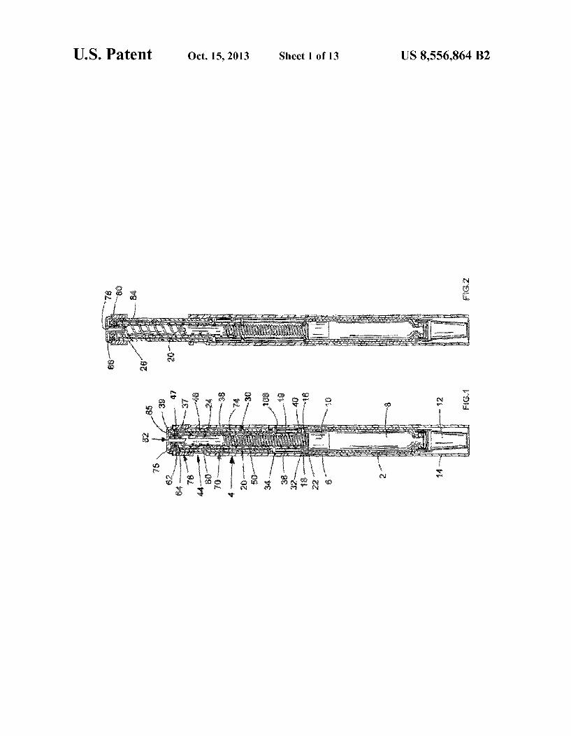
6 FIG. 1 shows a sectional view of a first embodiment of the
drug delivery device in accordance with the present invention in a first, cartridge full, position;
FIG.2 shows a sectional view of the drug delivery device of FIG. 1 in a second, maximum first dose dialed, position;
FIG.3 shows a sectional view of the drug delivery device of FIG. 1 in a third, maximum first dose dispensed, position;
FIG. 4 shows a sectional view of the drug delivery device of FIG. 1 in a fourth, final dose dialed, position; FIG.5 shows a sectional view of the drug delivery device of
FIG. 1 in a fifth, final dose dispensed, position: FIG. 6 shows a cut-away view of a first detail of the drug
delivery device of FIG. 1; FIG.7 shows apartially cut-away view of a second detail of
the drug delivery device of FIG. 1; FIG. 8 shows a partially cut-away view of a third detail of
the drug delivery device of FIG. 1; FIG. 9 shows the relative movement of parts of the drug
delivery device shown in FIG. 1 during dialing up of a dose; FIG. 10 shows the relative movement of parts of the drug
delivery device shown in FIG. 1 during dialing down of a dose;
FIG. 11 shows the relative movement of parts of the drug delivery device shown in FIG. 1 during dispensing of a dose;
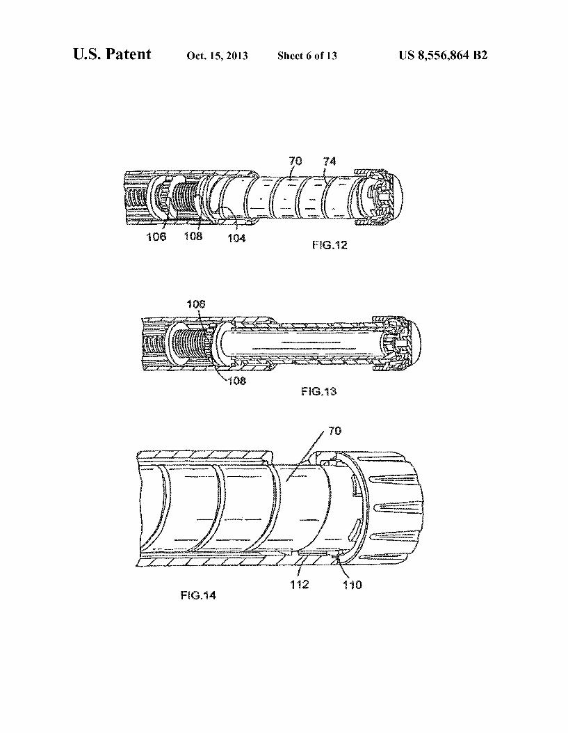
FIG. 12 shows a partially cut-away view of the drug deliv ery device of FIG. 1 in the second, maximum first dose dialed, position;
FIG. 13 shows a partially cut-away view of the drug deliv ery device of FIG. 1 in the fourth, final dose dialed, position;
FIG. 14 shows a partially cut-away view of the drug deliv ery device of FIG. 1 in one of the first, third or fifth positions:
FIG. 15 shows a cut-away view of a first part of a main housing of the drug delivery device of FIG. 1; and
FIG.16 shows a cut-away view of a second part of the main housing of the drug delivery device of FIG. 1;
FIG. 17 shows a sectional view of a second embodiment of the drive mechanism according to instant invention in a first, cartridge full, position.
FIG. 18 shows a sectional side view of a third embodiment of the drug delivery device in accordance with the present invention in a first, cartridge full, position;
FIG. 19 shows a sectional side view of the drug delivery device of FIG. 18 in a second, maximum first dose dialed, position;
FIG. 20 shows a sectional side view of the drug delivery device of FIG. 18 in a third, maximum first dose dispensed, position;
FIG. 21 shows a sectional side view of the drug delivery device of FIG. 18 in a fourth, final dose dialed, position;
FIG. 22 shows a sectional side view of the drug delivery device of FIG. 18 in a fifth, final dose dispensed, position;
FIG. 23 shows a fragment of the drug delivery device of FIG. 18 in a larger scale and
FIG. 24 shows a further fragment of the drug delivery device of FIG. 18 in a larger scale.
DETAILED DESCRIPTION
Example 1
Referring first to FIGS. 1 to 5, there is shown a drug delivery device in accordance with the present invention in a number of positions. The drug delivery device comprises a housing having a first
cartridge retaining part 2, and second main (exterior) housing part 4. A first end of the cartridge retaining means 2 and a second end of the main housing 4 are secured together by

US 8,556,864 B2 7
retaining features 6. In the illustrated embodiment, the car tridge retaining means 2 is secured within the second end of the main housing 4. A cartridge 8 from which a number of doses of a medicinal
product may be dispensed is provided in the cartridge retain ing part 2. A piston 10 is retained in a first end of the cartridge 8. A removable cap 12 is releasably retained over a second
end of the cartridge retaining part 2. In use the removable cap 12 can be replaced by a user with a suitable needle unit (not shown). A replaceable cap 14 is used to cover the cartridge retaining part 2 extending from the main housing 4. Prefer ably, the outer dimensions of the replaceable cap 14 are simi lar or identical to the outer dimensions of the main housing 4 to provide the impression of a unitary whole when the replaceable cap 14 is in position covering the cartridge retain ing part 2.
In the illustrated embodiment, an insert 16 is provided at a first end of the main housing 4. The insert 16 is secured against rotational or longitudinal motion. The insert 16 is provided with a threaded circular opening 18 extending there through. Alternatively, the insert may be formed integrally with the main housing 4 having the form of a radially inwardly directed flange having an internal thread. A first thread 19 extends from a first end of a piston rod 20.
The piston rod 20 is of generally circular section. The first end of the piston rod 20 extends through the threaded opening 18 in the insert 16. A pressure foot 22 is located at the first end of the piston rod 20. The pressure foot 22 is disposed to abut a second end of the cartridge piston 10. A second thread 24 extends from a second end of the piston rod 20. In the illus trated embodiment the second thread 24 comprises a series of part threads rather than a complete thread. The illustrated embodiment is easier to manufacture and helps to reduce the overall force required for a user to actuate the device when dispensing the medicinal product. The first thread 19 and the second thread 24 are oppositely
disposed. The second end of the piston rod 20 is provided with a receiving recess 26.
Adrive sleeve 30 extends about the piston rod 20. The drive sleeve 30 is generally cylindrical. The drive sleeve 30 is provided at a first end with a first radially extending flange 32. A second radially extending flange 34 is provided spaced a distance along the drive sleeve 30 from the first flange 32. An intermediate thread36 is provided on an outer part of the drive sleeve 30 extending between the first flange 32 and the second flange 34. A helical groove (thread) 38 extends along the internal surface of the drive sleeve 30. The second thread 24 of the piston rod 20 is adapted to work within the helical groove 38. A first end of the first flange 32 is adapted to conform to a
second side of the insert 16. A nut 40 is located between the drive sleeve 30 and the
main housing 4., disposed between the first flange 32 and the second flange 34. In the illustrated embodiment the nut 40 is a half-nut. This assists in the assembly of the device. The nut 40 has an internal thread matching the intermediate thread36. The outer surface of the nut 40 and an internal surface of the main housing 4 are keyed together by splines 42 (FIGS. 10, 11, 15 and 16) to prevent relative rotation between the nut 40 and the main housing 4, while allowing relative longitudinal movement therebetween. A shoulder 37 is formed between a second end of the drive
sleeve 30 and an extension 47 provided at the second end of the drive sleeve 30. The extension 47 has reduced inner and outer diameters in comparison to the remainder of the drive
10
15
25
30
35
40
45
50
55
60
65
8 sleeve 30. A second end of the extension 47 is provided with a radially outwardly directed flange 39. A clicker 50 and a clutch 60 are disposed about the drive
sleeve 30, between the drive sleeve 30 and a dose dial sleeve 70 (described below). The clicker 50 is located adjacent the second flange 34 of
the drive sleeve30. The clicker 50 is generally cylindrical and is provided at a first end with a flexible helically extending arm 52 (FIG. 6). A free end of the arm 52 is provided with a radially directed toothed member 54. A second end of the clicker 50 is provided with a series of circumferentially directed saw teeth 56 (FIG. 7). Each saw tooth comprises a longitudinally directed Surface and an inclined surface.
In an alternative embodiment (not shown) the clicker fur ther includes at least one spring member. The at least one spring member assists in the resetting of the clutch 60 follow ing dispense. The clutch 60 is located adjacent the second end of the
drive sleeve 30. The clutch 60 is generally cylindrical and is provided at a first end with a series of circumferentially directed saw teeth 66 (FIG. 7). Each saw tooth comprises a longitudinally directed Surface and an inclined surface. Towards the second end 64 of the clutch 60 there is located a radially inwardly directed flange 62. The flange 62 of the clutch 60 is disposed between the shoulder 37 of the drive sleeve 30 and the radially outwardly directed flange 39 of the extension 47. The second end of the clutch 60 is provided with a plurality of dog teeth 65 (FIG. 8). The clutch 60 is keyed to the drive sleeve 30 by way of splines (not shown) to prevent relative rotation between the clutch 60 and the drive sleeve30.
In the illustrated embodiment, the clicker 50 and the clutch. 60 each extend approximately half the length of the drive sleeve 30. However, it will be understood that other arrange ments regarding the relative lengths of these parts are pos sible. The clicker 50 and the clutch 60 are engaged as shown in
FIG. 7. A dose dial sleeve 70 is provided outside of the clicker 50
and clutch 60 and radially inward of the main housing 4. A helical groove 74 is provided about an outer surface of the dose dial sleeve 70. The main housing 4 is provided with a window 44 through
which a part of the outer surface of the dose dial sleeve may be seen. The main housing 4 is further provided with a helical rib (thread) 46, adapted to be seated in the helical groove (thread) 74 on the outer surface of the dose dial sleeve 70. The helical rib 46 extends for a single sweep of the inner surface of the main housing 4. A first stop 100 is provided between the splines 42 and the helical rib 46 (FIG. 15). A second stop 102. disposed at an angle of 180° to the first stop 100 is formed by a frame Surrounding the window 44 in the main housing 4 (FIG.16).
Conveniently, a visual indication of the dose that may be dialed, for example reference numerals (not shown), is pro vided on the outer surface of the dose dial sleeve 70. The window 44 conveniently only, allows to be viewed a visual indication of the dose currently dialed. A second end of the dose dial sleeve 70 is provided with an
inwardly directed flange in the form of a number of radially extending members 75. A dose dial grip 76 is disposed about an outer surface of the second end of the dose dial sleeve 70. An outer diameter of the dose dial grip 76 preferably corre sponds to the outer diameter of the main housing 4. The dose dial grip 76 is secured to the dose dial sleeve 70 to prevent relative movement therebetween. The dose dial grip 76 is

US 8,556,864 B2
provided with a central opening 78. An annular recess 80 located in the second end of the dose dial grip 76 extends around the opening 78.
Abutton 82 of generally 'T' section is provided at a second end of the device. A stem 84 of the button 82 may extend through the opening 78 in the dose dial grip 76, through the inner diameter of the extension 47 of the drive sleeve 30 and into the receiving recess 26 of the piston rod 20. The stem 84 is retained for limited axial movement in the drive sleeve 30 and against rotation with respect thereto. A head 85 of the button 82 is generally circular. A skirt 86 depends from a periphery of the head 85. The skirt 86 is adapted to be seated in the annular recess 80 of the dose dial grip 76.
Operation of the drug delivery device in accordance with the present invention will now be described. In FIGS. 9, 10 and 11 arrows A, B, C, D, E, F and G represent the respective movements of the button 82, the dose dial grip 76, the dose dial sleeve 70, the drive sleeve30, the clutch 60, the clicker 50 and the nut 40. To dial a dose (FIG.9) a user rotates the dose dial grip 76
(arrow B). With the clicker 50 and clutch 60 engaged, the drive sleeve 30, the clicker 50, the clutch 60 and the dose dial sleeve 70 rotate with the dose dial grip 76.
Audible and tactile feedback of the dose being dialed is provided by the clicker 50 and the clutch 60. Torque is trans mitted through the saw teeth 56.66 between the clicker 50 and the clutch 60. The flexible arm 52 deforms and drags the toothed member 54 over the splines 42 to produce a click. Preferably, the splines 42 are disposed such that each click corresponds to a conventional unit dose, or the like. The helical groove 74 on the dose dial sleeve 70 and the
helical groove 38 in the drive sleeve 30 have the same lead. This allows the dose dial sleeve 70 (arrow C) to extend from the main housing 4 and the drive sleeve 30 (arrow D) to climb the piston rod 20 at the same rate. At the limit of travel, a radial stop 104 (FIG. 12) on the dose dial sleeve 70 engages either the first stop 100 or the second stop 102 provided on the main housing 4 to prevent further movement. Rotation of the piston rod 20 is prevented due to the opposing directions of the overhauled and driven threads on the piston rod 20. The nut 40, keyed to the main housing 4, is advanced along
the intermediate thread 36 by the rotation of the drive sleeve 30 (arrow D). When the final dose dispensed position (FIGS. 4, 5 and 13) is reached, a radial stop 106 formed on a second surface of the nut 40 abuts a radial stop 108 on a first surface of the second flange 34 of the drive sleeve30, preventing both the nut 40 and the drive sleeve 30 from rotating further.
In an alternative embodiment (not shown) a first surface of the nut 40 is provided with a radial stop for abutment with a radial stop provided on a second surface of the first flange 32. This aids location of the nut 40 at the cartridge full position during assembly of the drug delivery device.
Should a user inadvertently dial beyond the desired dosage, the drug delivery device allows the dosage to be dialed down without dispense of medicinal product from the cartridge (FIG. 10). The dose dial grip 76 is counter rotated (arrow B). This causes the system to act in reverse. The flexible arm 52 preventing the clicker 50 from rotating. The torque transmit ted through the clutch 60 causes the saw teeth 56,66 to ride over one another to create the clicks corresponding to dialed dose reduction. Preferably the saw teeth 56,66 are so disposed that the circumferential extent of each saw tooth corresponds to a unit dose. When the desired dose has been dialed, the user may then
dispense this dose by depressing the button 82 (FIG. 11). This displaces the clutch 60 axially with respect to the dose dial sleeve 70 causing the dog teeth 65 to disengage. However the
10
15
25
30
35
40
45
50
55
60
65
10 clutch 60 remains keyed in rotation to the drive sleeve30. The dose dial sleeve 70 and associated dose dial grip 76 are now free to rotate (guided by the helical rib 46 located in helical groove 74). The axial movement deforms the flexible arm 52 of the
clicker 50 to ensure the saw teeth 56,66 cannot be overhauled during dispense. This prevents the drive sleeve 30 from rotat ing with respect to the main housing 4though it is still free to move axially with respect thereto. This deformation is sub sequently used to urge the clicker 50, and the clutch 60, back along the drive sleeve 30 to restore the connection between the clutch 60 and the dose dial sleeve 70 when pressure is removed from the button 82. The longitudinal axial movement of the drive sleeve 30
causes the piston rod 20 to rotate though the opening 18 in the insert 16, thereby to advance the piston 10 in the cartridge 8. Once the dialed dose has been dispensed, the dose dial sleeve 70 is prevented from further rotation by contact of a plurality of members 110 (FIG. 14) extending from the dose dial grip 76 with a corresponding plurality of stops 112 formed in the main housing 4 (FIGS. 15 and 16). In the illustrated embodi ment, the members 110 extendaxially from the dose dial grip 76 and have an inclined end surface. The Zero dose position is determined by the abutment of one of the axially extending edges of the members 110 with a corresponding stop 112.
Example 2
In another embodiment of the invention (FIG. 17) there is seen a drive mechanism comprising a second main housing 4 having a first end and a second end. A cartridge, containing medicinal product, can be mounted to the first end of the second main housing 4' and retained by any Suitable means. The cartridge and its retaining means are not shown in the illustrated embodiment. The cartridge may contain a number of doses of a medicinal product and also typically contains a displaceable piston. Displacement of the piston causes the medicinal product to be expelled from the cartridge via a needle (also not shown).
In the illustrated embodiment, an insert 16' is provided within the main housing 4'. The insert 16' is secured against rotational and axial motion with respect to the second main housing 4'. The insert 16' is provided with a threaded circular opening extending therethrough. Alternatively, the insert may be formed integrally with the second main housing 4. An internal housing 154 is also provided within the second
main housing 4'. The internal housing 154 is secured against rotational and axial motion with respect to the second main housing 4'. The internal housing 154 is provided with a cir cular opening extending through its length in which a series of longitudinally directed splines are formed. A helical thread 150 extends along the outer cylindrical surface of the internal housing 154. Alternatively, the internal housing may be formed integrally with the second main housing 4' and/or with the insert 16'. A first thread 19' extends from a first end of a piston rod 20'.
The piston rod 20' is of generally circular section. The first end of the piston rod 20' extends through the threaded opening in the insert 16' and the first thread 19" of the piston rod 20' is engaged with the thread of the insert 16'. A pressure foot 22 is located at the first end of the piston rod 20'. The pressure foot 22' is disposed to abut a cartridge piston (not shown). A second thread 24 extends from a second end of the piston rod 20'. The first thread 19" and the second thread 24' are oppo sitely disposed. A drive sleeve 30' extends about the piston rod 20". The
drive sleeve 30' is generally cylindrical. The drive sleeve30' is

US 8,556,864 B2 11
provided at a first end with a first radially extending flange 32. A second radially extending flange 34" is provided, spaced a distance along the drive sleeve 30' from the first flange 32". An external helical thread (not shown) is provided on the outer part of the drive sleeve 30' extending between the first flange 32 and the second flange 34'. An internal helical thread extends along the internal surface of the drive sleeve 30'. The second thread 24' of the piston rod 20' is engaged with the internal helical thread of the drive sleeve 30'. A nut 40' is located between the drive sleeve 30' and the
internal housing 154, disposed between the first flange 32' and the second flange 34' of the drive sleeve 30'. The nut 40' can be either a half-nut or a full-nut. The nut 40' has an internal thread that is engaged with the external helical thread of the drive sleeve 30'. The outer surface of the nut 40' and an internal surface of the internal housing 154 are keyed together by means of longitudinally directed splines to prevent relative rotation between the nut 40' and the internal housing 154, while allowing relative longitudinal movement therebe tWeen.
A clicker 50' and a clutch 60' are disposed about the drive sleeve 30', between the drive sleeve 30' and the internal hous ing 154. The clicker 50' is located adjacent the second flange 34" of
the drive sleeve 30'. The clicker 50' includes at least one spring member (not shown). The clicker 50' also includes a set of teeth (not shown) having a triangular profile disposed towards the second end of the drive mechanism. When com pressed, the at least one spring member of the clicker 50' applies an axial force between the flange 34 of the drive sleeve 30' and the clutch 60'. The outer Surface of the clicker 50' and an internal surface of the internal housing 154 are keyed together by means of longitudinally directed splines to prevent relative rotation between the clicker 50' and the inter nal housing 154, while allowing relative longitudinal move ment therebetween. The clutch 60' is located adjacent the second end of the
drive sleeve 30'. The clutch 60' is generally cylindrical and is provided at its first end with a plurality of teeth of triangular profile disposed about the circumference (not shown), that act upon the teeth of the clicker 50'. Towards the second end of the clutch 60' there is located a shoulder 158. The shoulder 158 of the clutch 60' is disposed between the internal housing 154 and a radially inwardly directed flange of the dose dial grip. 76' (described below). The shoulder 158 of the clutch 60' is provided with a plurality of dog teeth (not shown) extend ing in the direction of the second end of the drive mechanism. The clutch 60' is keyed to the drive sleeve 30' by way of splines (not shown) to prevent relative rotation between the clutch 60' and the drive sleeve 30'. A dose dial sleeve 70' is provided outside of the internal
housing 154 and radially inward from the second main hous ing 4'. A helical thread is provided on an inner surface of the dose dial sleeve 70'. The helical thread of the dose dial sleeve 70' is engaged with the helical thread 150 of the internal housing 154.
The second main housing 4" is provided with a window (not shown) through which part of the outer surface of the dose dial sleeve 70' may be viewed. Conveniently, a visual indica tion of the dose that may be dialed, for example reference numerals (not shown), is provided on the outer Surface of the dose dial sleeve 70'. Conveniently, the window of the second main housing 4'allows only the dose that is currently dialed to be viewed. A dose dial grip. 76' is located towards the second end of the
drive mechanism. The dose dial grip 76' is secured against rotational and axial motion within respect to the dose dial
10
15
25
30
35
40
45
50
55
60
65
12 sleeve 70'. The dose dial grip 76' is provided with a radially inwardly directed flange 160. The radially inwardly directed flange 160 of the dose dial grip. 76' is provided with a plurality of dog teeth (not shown) extending in the direction of the first end of the drive mechanism to abut the dog teeth of the clutch 60'. Coupling and decoupling of the dog teeth of the dose dial grip 76' with the dog teeth of the clutch 60' provides a releas able clutch between the dose dial grip. 76' and the clutch 60'. A button 82 of generally T shaped cross-section is pro
vided at a second end of the drive mechanism. A cylindrical feature of the button 82 extends towards the first end of the drive mechanism, through an opening in the dose dial grip. 76' and into a recess in the drive sleeve 30'. The cylindrical feature of the button 82 is retained for limited axial move ment in the drive sleeve 30' and against rotation with respect thereto. The cylindrical feature of the button 82 has lugs extending radially (not shown) that abut the second Surface of the shoulder 158 of the clutch 60'. The second end of the button 82" is generally circular and has a cylindrical skirt about its periphery that descends towards the first end of the drive mechanism. The skirt of the button 82" is located radi ally inward from the dose dial grip 76'.
Operation of the drive mechanism in accordance with the present invention will now be described. To dial a dose, a user rotates the dose dial grip. 76". The
spring member of the clicker 50' applies an axial force to the clutch 60' in the direction of the second end of the drive mechanism. The force exerted by the spring member of the clicker 50' couples the dog teeth of the clutch 60' to the dog teeth of the dose dial grip. 76' for rotation. As the dose dial grip 76' is rotated, the associated dose dial sleeve 70', the drive sleeve 30' and the clutch 60' all rotate in unison.
Audible and tactile feedback of the dose being dialed is provided by the clicker 50' and the clutch 60'. As the clutch 60' is rotated, torque is transmitted from the teeth at the first end of the clutch 60' and the teeth of the clicker 50'. The clicker 50' cannot rotate with respect to the internal housing 154, so the at least one spring member of the clicker 50' deforms allowing the teeth of the clutch 60' to jump over the teeth of the clicker 50" producing an audible and tactile click. Preferably, the teeth of the clicker 50' and the teeth of the clutch 60' are disposed Such that each click corresponds to a conventional unit of the medicinal product, or the like. The helical thread of the dose dial sleeve 70' and the inter
nal helical thread of the drive sleeve 30' have the same lead. This allows the dose dial sleeve 70' to advance along the thread 150 of the internal housing 154 at the same rate as the drive sleeve 30' advances along the second thread 24 of the piston rod 20". Rotation of the piston rod 20' is prevented due to the opposing direction of the first thread 19" and the second thread 24' of the piston rod 20'. The first thread 19" of the piston rod 20' is engaged with the thread of the insert 16" and so the piston rod 20' does not move with respect to the second main housing 4' while a dose is dialed. The nut 40', keyed to the internal housing 154, is advanced
along the external thread of the drive sleeve 30' by the rotation of the drive sleeve 30'. When a user has dialed a quantity of medicinal product that is equivalent to the deliverable volume of the cartridge, the nut 40' reaches a position where it abuts the second flange 34 of the drive sleeve 30'. A radial stop formed on the second surface of the nut 40' contacts a radial stop on the first surface of the second flange 34" of the drive sleeve 30', preventing both the nut 40' and the drive sleeve30' from being rotated further.
Should a user inadvertently dial a quantity greater than the desired dosage, the drive mechanism allows the dosage to be corrected without dispense of medicinal product from the

US 8,556,864 B2 13
cartridge. The dose dial grip. 76' is counter-rotated. This causes the system to act in reverse. The torque transmitted through the clutch 60' causes the teeth at the first end of the clutch 60' to ride over the teeth of the clicker 50' to create the clicks corresponding to the dialed dose reduction. When the desired dose has been dialed, the user may then
dispense this dose by depressing the button 82 in the direction of the first end of the drive mechanism. The lugs of the button 82'apply pressure to the second surface of the shoulder 158 of the clutch 60', displacing the clutch 60'axially with respect to the dose dial grip 76". This causes the dog teeth on the shoul der 158 of the clutch 60' to disengage from the dog teeth of the dose dial grip. 76'. However, the clutch 60' remains keyed in rotation to the drive sleeve 30'. The dose dial grip. 76' and associated dose dial sleeve 70' are now free to rotate (guided by the helical thread 150 of the internal housing 154).
The axial movement of the clutch 60' deforms the spring member of the clicker 50' and couples the teeth at the first end of the clutch 60' to the teeth of the clicker 50' preventing relative rotation therebetween. This prevents the drive sleeve 30' from rotating with respect to the internal housing 154, though it is still free to move axially with respect thereto.
Pressure applied to the button 82 thus causes the dose dial grip 76' and the associated dose dial sleeve 70' to rotate into the second main housing 4'. Under this pressure the clutch 60', the clicker 50' and the drive sleeve 30' are moved axially in the direction of the first end of the drive mechanism, but they do not rotate. The axial movement of the drive sleeve 30' causes the piston rod 20' to rotate though the threaded opening in the insert 16', thereby to advance the pressure foot 22". This applies force to the piston, causing the medicinal product to be expelled from the cartridge. The selected dose is delivered when the dose dial grip 76' returns to a position where it abuts the second main housing 4'. When pressure is removed from the button 82', the defor
mation of the spring member of the clicker 50' is used to urge the clutch 60' back along the drive sleeve 30' to re-couple the dog teeth on the shoulder 158 of the clutch 60' with the dog teeth on the dose dial grip. 76". The drive mechanism is thus reset in preparation to dial a Subsequent dose.
Example 3
Referring to FIGS. 18 to 22 there may be seen a drug delivery device in accordance with the present invention. The drug delivery device comprises a two-part housing 2" within which are located a cartridge 4" containing a medicinal prod uct, means for setting or selecting the dose of medicinal product to be expelled and means for expelling the selected dose of medicinal product. The housing 2" is generally cylin drical in shape and houses a rack 6" to be described in more detail below. The cartridge 4" is located within a first part 8" of the housing 2". The dose setting means and the means for expelling the selected dose of medicinal product are retained, that is held, within a second part 10" of the housing 2". The first part 8" of the housing 2" and the second part 10" of the housing 2" may be secured together by any Suitable means.
The cartridge 4" may be secured in position in the first part 8" of the housing 2" by any suitable means. A needle unit may be secured to a first end of the cartridge 4". A temporary covering 12" is shown in this position in the Figures. The cartridge 4" further comprises a displaceable piston 14". Advancing the piston 10" towards the first end of the cartridge 4" causes the medicinal product to be expelled from the cartridge 4" through the needle unit. A cap 16" is provided to
10
15
25
30
35
40
45
50
55
60
65
14 cover the needle unit when the drug delivery device is not in use. The cap 16" may be releasably secured to the 1 housing 2" by any suitable means. The dose setting means and the means for expelling the
selected dose of medicinal product will now be described in more detail. The rack 6" is located within a drive sleeve 18" located within the housing 2" and is fixed both axially and rotationally with respect to the housing 2" by any suitable means. The drive sleeve 18" comprises an internally threaded portion 20", which extends along substantially the entire internal surface of the sleeve. An internal toothed gear 22" is located within the drive sleeve 18" and has helical teeth which match the pitch of the internal thread of the drive sleeve 18". The internal thread of the drive sleeve 18" is a multistart thread with a lead which is the same as the lead of the helical thread of the dose dial sleeve, which will be described later. The drive sleeve 18" terminates in an externally threaded section 24" which extends from an end of the sleeve as far as an external circumferential flange 26" which projects from the drive sleeve 18". A limiting nut 28" is mounted for rotation on the externally threaded section 24" of the sleeve 14". The limiting nut 28" is keyed to the housing 2" by means of a plurality of longitudinally extending splines 30" which extend along the internal surface of the first portion 8" of the housing 2". In the illustrated embodiment, the limiting nut 28" is shown as a half-nut, but a full nut could be used. A piston rod 32" is provided extending along the length of
the rack 6" and through a hole in the end of the rack 6". The piston rod 32" is generally elongate and is provided with a pressure foot 34". In use the pressure foot 34" is disposed to abut the cartridge piston 14". The toothedgear 22" is mounted on the end of the piston rod 32" remote from the pressure foot 34" in a journal bearing (not shown). A dose dial sleeve 36" of generally cylindrical form com
prises a first section 38" of first diameter and a second section 40" of larger second diameter. The first section is located within the housing 2". The second section 40" of the dose dial sleeve 36" is pref
erably of the same outer diameter as the housing 2". The second part 10" of the housing 2" comprises an external sleeve portion 42" Surrounding a coaxial internal sleeve por tion 44". The external sleeve portion 42" is closed to the internal sleeveportion 44"at a circular internal flange portion 46". The first section 38" of the dose dial sleeve 36" is located within the second part 10" of the housing 2", between the external sleeve portion 42" and the internal sleeve portion 44". An inner surface of the first section 38" and the outer surface of the internal sleeve portion 44" are provided with interengaging features to provide a helical thread 48" between the internal sleeveportion 44" of the second part 10" of the housing 2" and the dose dial sleeve 36". This helical thread 48" has the same lead as the internal thread of the drive sleeve 18", as noted above. Within the helical track, a helical rib provided on the inner surface of the dose dial sleeve 36" may run. This enables the dose dial sleeve 36" to rotate about and along the housing 2". The second section 40" of the dose dial sleeve 36" is pro
vided with an end wall 50" adjacent its free end, which defines a central receiving area 52" between the end wall 50" and the free end of the dose dial sleeve 36". A through hole 54" is provided in the end wall 50". A dose button 56" of generally “T” shaped configuration is provided, the head 58" of which is retained within the receiving area 52" and the stem 60" of which is sized to pass through the through hole 54". The stem 60" of the button 56" is provided with a plurality offingers 62"

US 8,556,864 B2 15
that are deformable to pass through the through hole 54" of the end wall 50" only in the direction away from the free end of the dose dial sleeve 36". The drive sleeve 18" is closed at its end remote from the
externally threaded section 24" by an apertured end wall 64" from which a plurality of engagement features 66" project external to the drive sleeve 18". A Substantially U-shaped locking spring 68" comprising
first and second legs 70", 72" joined by a link portion 74" is provided for longitudinal mounting on the exterior of the drive sleeve 18". The link portion 74" is of a length which is substantially equal to the external diameter of the drive sleeve 18". Each of the legs 70", 72" of the locking spring 68" terminates in a latch portion 76", the function of which will be described later. When the device is assembled, the locking spring 68"urges
the dose button 56" axially away from the piston rod 32" and drive sleeve 18", towards the inside of the end wall 50" of the dose dial sleeve 36". In this position, the dose button 56" is locked with respect to rotation with the dose dial sleeve 36". The dose button 56" is also permanently locked with respect to rotation with the drive sleeve 18". An outer surface of the first section of the dose dial sleeve
36" is provided with graphics 82". The graphics are typically a sequence of reference numerals. The housing 2" is provided with an aperture or window 84" through which a portion of the graphics, representing a dosage value selected by the user, may be viewed. The graphics 82" may be applied to the dose dial sleeve36"
by any suitable means. The graphics 82" may be printed directly on the dose dial sleeve 36" or may be provided in the form of a printed label encircling the dose dial sleeve 36". Alternatively the graphics may take the form of a marked sleeve clipped to the dose dial sleeve 36". The graphics may be marked in any Suitable manner, for example by laser mark 1ng. The external circumferential flange 26" which projects
from the drive sleeve 18" is provided with a pair of diametri cally opposed through apertures 78" sized to receive the cor responding latch portions 76" of the locking spring 68". A clicker projection 80" from the outer edge of the flange 26" is associated with each through aperture 78".
In FIG. 18, the drug delivery device is provided with a filled cartridge 4". To operate the drug delivery device a user must first select a dose. To set a dose the dose dial sleeve 36" is rotated with respect to the housing 2" until the desired dose value is visible through the window 84". The drive sleeve 18" is linked to the dose dial sleeve 36" and spirals out at the same rate during dialing. During the dialing of a dose, the locking spring 68 is straight and urges the dose button 56" axially away from the piston rod 32" and drive sleeve 18", towards the inside of the end wall 50" of the dose dial sleeve 36", thereby providing a clutch mechanism. The drive sleeve 18" therefore rotates over the toothed gear 22" that is located inside it. The relative rotation between the drive sleeve 18" and the housing 2" causes an audible confirmation of the dose being dialed by engagement of the two clicker projections 80" with the splines 30" which extend along the internal surface of the first portion 8" of the housing 2".
The limiting nut 28" climbs up the drive sleeve 18" in proportion to the dose dialed. The position of the limiting nut 28", which only moves along the external thread of the drive sleeve 18" when there is relative rotation between the drive sleeve 18" and the housing 2", corresponds to the amount of medicinal product remaining in the cartridge 4". Once a desired dose has been set (as shown for example in
FIG. 19), to deliver the dose the user depresses the dose button
10
15
25
30
35
40
45
50
55
60
65
16 56" to urge the button 56" against the locking spring 68". As the dose button 56" pushes down on the spring 68", the clutch between the dose button 56" and the dose dial sleeve 36" is disengaged. The axial force applied from the dose button 56" onto the dose dial sleeve 36" causes the dose dial sleeve 36" to spin into the housing 2" on the helical thread between the dose dial sleeve 36" and the housing 2". The locking spring 68" deforms and the legs of the spring move axially down the drive sleeve 18". The latch portions 76" of the locking spring 68" engage in the through apertures 78" on the external flange 26" which projects from the drive sleeve 18" and maintain engagement between the clicker projections 80" of the flange 26" with the grooves between the splines 30", locking the drive sleeve to the housing 2" and preventing the drive sleeve 18" from rotation relative to the housing 2" during dispensing of the dose. The drive sleeve 18" is thus prevented from spinning and moves axially in, causing the toothedgear 22" to rotate against the fixed rack 6". The toothedgear 22", together with the piston rod 32" on which it is mounted, move along the rack 6" a distance corresponding to one half of the dis tance by which the drive sleeve 18" moves axially, creating a 2:1 mechanical advantage. This has the two-fold benefit of allowing the display on the dose dial sleeve 36" to be larger for a given amount of travel of the piston 14" within the cartridge 4", that is for a given amount of medicament to be dispensed and secondly of halving the force required to dis pense the dose. The piston rod 32" is driven through the drive sleeve 18"
towards the first end of the drug delivery device, thereby to advance the cartridge piston 14" and expel the desired dose of medicinal product. The piston rod 32" continues to advance until the drive sleeve 18" and dose dial sleeve 36" have returned to their initial positions (FIG. 20).
It can be seen that the dose selecting means and the dose expelling means extend beyond a second end of the housing 2" as the dose is selected and are returned within the housing 2" as the selected dose is expelled.
Further dosages may be delivered as required. FIG. 21 shows an example of a Subsequently selected dosage. As noted above, the position of the limiting nut 28" along the external thread of the drive sleeve 18" corresponds to the amount of medicinal product remaining in the cartridge 4". such that when the nut 28" reaches the external flange 26" and can rotate no further this corresponds to no medicinal product remaining in the cartridge 4". It will be seen that ifa user seeks to select a quantity of medical product greater than that remaining in the cartridge 4", this cannot be done since when the nut 28" stops rotating against the drive sleeve 18", the drive sleeve 18" and the housing 2" will become locked together preventing rotation of the drive sleeve 18" and hence the dose dial sleeve 36". This prevents the setting of a larger dose than the amount of medical product remaining within the cartridge 4". FIG.22 shows a drug delivery device accord ing to the present invention in which the entire medicinal product within the cartridge 4" has been expelled. The illustrated embodiment of the device according to the
invention further comprises a maximum dosage dial end stop. When the dose dial sleeve 36" is dialed fully out, the external flange 26" on the drive sleeve 18" engages the internal flange 46" in the housing 2". It will be seen that if the user tries to dial beyond the maximum dosage, this cannot be done. When the drive sleeve 18" stops rotating against the housing 2", the dose dial sleeve is also prevented from rotating. The reaction between the external flange 44" and the internal flange 86" indicates to the user that the maximum dose has been dialed.

US 8,556,864 B2 17
The invention claimed is: 1. A drive mechanism for use in a drug delivery device
comprising: a housing having a helical thread; a dose dial sleeve having a helical thread engaged with the
helical thread of the housing: a drive sleeve having two radially extending flanges spaced
a distance apart and having an outer helical thread there between, where the drive sleeve is releasably connected to the dose dial sleeve;
a piston rod threadedly engaged with the drive sleeve; and a clutch mechanism located between the dose dial sleeve and the drive sleeve.
2. A drive mechanism for use in a drug delivery device is provided comprising:
a housing having a helical thread along an inner surface, a dose dial sleeve having a helical thread on an outer
Surface engaged with the helical thread of the housing: a drive sleeve releasably connected to the dose dial sleeve;
and a clutch mechanism located between the dose dial sleeve
and the drive sleeve; wherein the clutch mechanism is configured such that,
a) when the dose dial sleeve and the drive sleeve are coupled, both are allowed to rotate with respect to the housing; and
b) when the dose dial sleeve and the drive sleeve are de-coupled, rotation of the dose dial sleeve with respect to the housing is allowed, while rotation of the drive sleeve with respect to the housing is prevented, whereby axial movement of the drive sleeve is allowed so that a force is transferred in a longitudinal direction to a proximal end of the drug delivery device.
3. The drive mechanism of claim 2 further comprising a piston rod having a first external thread and a second external thread, where the first external thread is threadedly engaged with an insert, and where the second external thread is thread edly engaged with an internal thread on the drive sleeve.
4. The drive mechanism of claim 2 where the drive sleeve has two radially extending flanges spaced a distance apart and having an outer helical thread there between and where the drive sleeve is releasably connected to the dose dial sleeve.
5. The drive mechanism of claim 4 further comprising a dose limiting mechanism.
6. The drive mechanism of claim 5 wherein said dose limiting mechanism is disposed between said first radially extending flange and said second radially extending flange.
7. The drive mechanism of claim 6 wherein said dose limiting mechanism comprises a nut threadedly engaged with the outer helical thread of the drive sleeve and is splined to an
10
15
25
30
35
40
45
50
18 internal surface of the housing to prevent the nut from rotating while allowing relative longitudinal movement between the two radially extending flanges, whereby the longitudinal movement is proportional to dispensed doses.
8. A drive mechanism for use in a drug delivery device comprising:
a) a main housing having a first end and a second end, a helical thread having a first lead, an insert rotationally fixed to the housing having a thread with a second lead;
b) a dose dial sleeve having a helical thread engaged with the helical thread of the main housing configured so that during dose selection the dose dial sleeve rotates and extends axially from the second end of the main housing and during dose delivery rotates and moves axially back into the main housing:
c) a tubular drive sleeve having an internal surface and an outer surface having disposed thereon an intermediate thread, where the tubular drive sleeve is releasably con nected to the dose dial sleeve through a clutch located between the dose dial sleeve and the tubular drive sleeve and where the tubular drive sleeve has an internal helical thread having a lead equal to the first lead;
d) a piston rod having a first external thread and a second external thread, where the first external thread has a lead equal to the second lead that is different and of opposite disposition than the first lead and is threadedly engaged with the insert, and where the second external thread is threadedly engaged with the internal thread of the tubu lar drive sleeve;
wherein, when the dose dial sleeve and the tubular drive sleeve are
coupled during dose section, both are allowed to rotate with respect to both the main housing and the piston rod; and
when the dose dial sleeve and the tubular drive sleeve are de-coupled during dose delivery, rotation of the dose dial sleeve with respect to the main housing is allowed, while rotation of the tubular drive sleeve with respect to the main housing is prevented, whereby axial movement of the tubular drive sleeve is allowed causing the piston rod to rotate through the tread of the insert and moving axially through the insert so that a force is transferred from the piston rod to a cartridge piston.
9. The drive mechanism of claim 8 wherein the intermedi ate thread is disposed between two radially extending flanges on the outer surface of the tubular drive sleeve.
10. The drive mechanism of claim 8 wherein the opposite disposition of the second lead of the first external thread compared to the first lead prevents the piston rod from moving during dose selection.
ck ck ck k ck

UNITED STATES PATENT AND TRADEMARK OFFICE
CERTIFICATE OF CORRECTION
PATENT NO. : 8,556,864 B2 Page 1 of 1 APPLICATIONNO. : 13/075212 DATED : October 15, 2013 INVENTOR(S) : Robert Frederick Veasey et al.
It is certified that error appears in the above-identified patent and that said Letters Patent is hereby corrected as shown below:
On the title page, item 30 Foreign Application Priority Data, please delete “0301822.0 and add --0304822.0-
Signed and Sealed this Twenty-second Day of March, 2016
74-4-04- 2% 4 Michelle K. Lee
Director of the United States Patent and Trademark Office