(12) United States Patent de Juan, Jr. et al. Dec. 9, 2014 · 2005.0113806 A1 5, 2005 De Carvalho...
123
(12) United States Patent de Juan, Jr. et al. (10) Patent No.: (45) Date of Patent: USOO8905963B2 US 8,905,963 B2 Dec. 9, 2014 (54) INJECTORAPPARATUS AND METHOD FOR (51) Int. Cl. DRUG DELIVERY A6M I/00 (2006.01) A6DF 9/00 (2006.01) (71) Applicant: ForSight Vision4, Inc. A6M5/78 (2006.01) A6M 5/3 (2006.01) (72) Inventors: Eugene de Juan, Jr., Menlo Park, CA A6M5/42 (2006.01) (US); Signe Erickson, Menlo Park, CA A61M 39/02 (2006.01) (US); Randolph E. Campbell, Menlo (52) U.S. Cl. Park, CA (US); Darren Doud, San Jose, CPC. A61F 9/0008 (2013.01); A61M 2039/0276 CA (US); Michael Barrett, Menlo Park, CA (US); David Batten, Menlo Park (2013.01); A61M 5/178 (2013.01); A61M CA (US). Christina Skieller Menlo 39/0247 (2013.01); A61M39/0208 (2013.01); Park CA (US); Greg Stine Menlo Park A61F 9/0017 (2013.01); A61M 2039/027 CA (US) s g s s (2013.01); A61M 5/31 (2013.01); A61M 5/14276 (2013.01) (73) Assignee: ForSight Vision4, Inc., Menlo Park, CA USPC ............................................... 604/44; 604/27 (US) (58) Field of Classification Search CPC ................... A61M 5/1582: A61M 2025/0031; (*) Notice: Subject to any disclaimer, the term of this A61M 2025/0039; A61F 9/00736 patent is extended or adjusted under 35 USPC ........................................ 604/44, 117, 43, 27 U.S.C. 154(b) by 59 days. See application file for complete search history. (21) Appl. No.: 13/889,328 (56) References Cited (22) Filed: May 7, 2013 U.S. PATENT DOCUMENTS O O 2,564,977 A 8, 1951 Hu et al. (65) Prior Publication Data 2,585,815 A 2, 1952 McLintock 2,886,497 A 5, 1959 Butler US 2013/0245544A1 Sep. 19, 2013 3,232,117 A 2, 1966 Gilmont 3.416,530 A 12/1968 Ness 3,618,604. A 11/1971 Ness Related U.S. Application Data 3,641.237 A 2f1972 Gould et al. 3,828,777 A 8, 1974 Ness (63) Continuation of application No. 13/814,461, filed as 3,831,583 A 8/1974 Edmunds, Jr. et al. application No. PCT/US2011/046812 on Aug. 5, 3,845,201. A 10/1974 Haddad et al. 2011 3,902,495 A 9, 1975 Weiss et al. 3,914.402 A 10, 1975 Shell (60) Provisional application No. 61/371,154, filed on Aug. 3,916,899 A EE Elyst al. 5, 2010, provisional application No. 61/371,169, filed El A 2. E. on Aug. 5, 2010, provisional application No. 3,949,750 A 4, 1976 Freeman 61/495,251, filed on Jun. 9, 2011, provisional 3,961,628 A 6, 1976 Arnold application No. 61/495,718, filed on Jun. 10, 2011, 3,977.404 A 8, 1976 Theeuwes provisional application No. 61/499,095, filed on Jun. S. A 13375 Ea 20, 2011, provisional application No. 61/501,021, 4.014333 A 3/1977 McIntyre filed on Jun. 24, 2011, provisional application No. 4,014,334 A 3, 1977 Theeuwes et al. 61/504,038, filed on Jul. 1, 2011. 4,014,335 A 3, 1977 Arnold 32 -167 16
Transcript of (12) United States Patent de Juan, Jr. et al. Dec. 9, 2014 · 2005.0113806 A1 5, 2005 De Carvalho...

(12) United States Patent de Juan, Jr. et al.
(10) Patent No.: (45) Date of Patent:
USOO8905963B2
US 8,905,963 B2 Dec. 9, 2014
(54) INJECTORAPPARATUS AND METHOD FOR (51) Int. Cl. DRUG DELIVERY A6M I/00 (2006.01)
A6DF 9/00 (2006.01) (71) Applicant: ForSight Vision4, Inc. A6M5/78 (2006.01)
A6M 5/3 (2006.01) (72) Inventors: Eugene de Juan, Jr., Menlo Park, CA A6M5/42 (2006.01)
(US); Signe Erickson, Menlo Park, CA A61M 39/02 (2006.01) (US); Randolph E. Campbell, Menlo (52) U.S. Cl. Park, CA (US); Darren Doud, San Jose, CPC. A61F 9/0008 (2013.01); A61M 2039/0276 CA (US); Michael Barrett, Menlo Park, CA (US); David Batten, Menlo Park (2013.01); A61M 5/178 (2013.01); A61M CA (US). Christina Skieller Menlo 39/0247 (2013.01); A61M39/0208 (2013.01); Park CA (US); Greg Stine Menlo Park A61F 9/0017 (2013.01); A61M 2039/027 CA (US) s g s s (2013.01); A61M 5/31 (2013.01); A61M
5/14276 (2013.01) (73) Assignee: ForSight Vision4, Inc., Menlo Park, CA USPC ............................................... 604/44; 604/27
(US) (58) Field of Classification Search CPC ................... A61M 5/1582: A61M 2025/0031;
(*) Notice: Subject to any disclaimer, the term of this A61M 2025/0039; A61F 9/00736 patent is extended or adjusted under 35 USPC ........................................ 604/44, 117, 43, 27 U.S.C. 154(b) by 59 days. See application file for complete search history.
(21) Appl. No.: 13/889,328 (56) References Cited
(22) Filed: May 7, 2013 U.S. PATENT DOCUMENTS
O O 2,564,977 A 8, 1951 Hu et al. (65) Prior Publication Data 2,585,815 A 2, 1952 McLintock
2,886,497 A 5, 1959 Butler US 2013/0245544A1 Sep. 19, 2013 3,232,117 A 2, 1966 Gilmont
3.416,530 A 12/1968 Ness 3,618,604. A 11/1971 Ness
Related U.S. Application Data 3,641.237 A 2f1972 Gould et al. 3,828,777 A 8, 1974 Ness
(63) Continuation of application No. 13/814,461, filed as 3,831,583 A 8/1974 Edmunds, Jr. et al. application No. PCT/US2011/046812 on Aug. 5, 3,845,201. A 10/1974 Haddad et al. 2011 3,902,495 A 9, 1975 Weiss et al.
3,914.402 A 10, 1975 Shell (60) Provisional application No. 61/371,154, filed on Aug. 3,916,899 A EE Elyst al.
5, 2010, provisional application No. 61/371,169, filed El A 2. E. on Aug. 5, 2010, provisional application No. 3,949,750 A 4, 1976 Freeman 61/495,251, filed on Jun. 9, 2011, provisional 3,961,628 A 6, 1976 Arnold application No. 61/495,718, filed on Jun. 10, 2011, 3,977.404 A 8, 1976 Theeuwes provisional application No. 61/499,095, filed on Jun. S. A 13375 Ea 20, 2011, provisional application No. 61/501,021, 4.014333 A 3/1977 McIntyre filed on Jun. 24, 2011, provisional application No. 4,014,334 A 3, 1977 Theeuwes et al. 61/504,038, filed on Jul. 1, 2011. 4,014,335 A 3, 1977 Arnold
32
-167
16

US 8,905,963 B2 Page 2
4,034,756 A 7/1977 Higuchi et al. 5,836,935 A 11/1998 Ashton et al. 4,034,758 A 7, 1977 Theeuwes 5,868,697 A 2f1999 Richter et al. 4,077.407 A 3, 1978 Theeuwes et al. 5,902,598 A 5/1999 Chen et al. 4,111.201 A 9, 1978 Theeuwes 5,916,584 A 6/1999 O’Donoghue et al. 4,111,203 A 9, 1978 Theeuwes 5,928,662 A 7/1999 Phillips 4,135,514 A 1/1979 Zaffaroni et al. 5,951,512 A 9, 1999 Dalton 4,160,452 A 7, 1979 Theeuwes 5,968,008 A 10, 1999 Grams 4,164,559 A 8/1979 Miyata et al. 5,972,369 A 10, 1999 Roorda et al. 4,179,497 A 12/1979 Cohen et al. 5,985,328 A 11/1999 Chu et al. 4,186,184 A 1, 1980 Zaffaroni 6,001,386 A 12/1999 Ashton et al. 4,200,098 A 4/1980 Ayer et al. 6,123,861 A 9/2000 Santini, Jr. et al. 4,220,152 A 9, 1980 Dresback 6,196,993 B1 3/2001 Cohan et al. 4,220,153 A 9, 1980 Dresback 6,251,090 B1 6/2001 Avery et al. 4,256,108 A 3, 1981 Theeuwes 6,303.290 B1 10/2001 Liu et al. 4,298,000 A 11, 1981 Thill et al. 6,331,313 B1 12/2001 Wong et al. 4,300,557 A 1 1/1981 Refojo et al. 6,331,523 B1 12/2001 Klavin et al. 4,309.776 A 1/1982 Berguer 6,375,972 B1 4/2002 Guo et al. 4.326,525 A 4, 1982 Swanson et al. 6,395,300 B1 5, 2002 Straub et al. 4,327,725 A 5, 1982 Cortese et al. 6,413,540 B1 7/2002 Yaacobi 4,343,787 A 8, 1982 Katz 6,416,777 B1 7/2002 Yaacobi 4,439,196 A 3/1984 Higuchi 6.420,399 B1 7/2002 Graffet al. 4,439,198 A 3/1984 Brightman, II et al. 6,472,162 B1 10/2002 Coelho et al. 4.475,916 A 10, 1984 Himmelstein 6,605,066 B1 8/2003 Gravagna et al. 4.484.922 A 11, 1984 Rosenwald 6,663,668 B1 12/2003 Chaouk et al. 4,519,801 A 5/1985 Edgren 6,669,950 B2 12/2003 Yaacobi 4,609,374. A 9/1986 Ayer 6,685,940 B2 2/2004 Andya et al. 4,627,850 A 12/1986 Deters et al. 6,713,081 B2 3/2004 Robinson et al. 4,634,418 A 1, 1987 Binder 6,719,750 B2 4/2004 Varner et al. 4,634,427 A 1, 1987 Hannula et al. 6,740,077 B1 5/2004 Brandau et al. 4,673.405 A 6, 1987 Guittard et al. 6,756,049 B2 6/2004 Brubaker et al. 4,693,886 A 9/1987 Ayer 6,756,058 B2 6/2004 Brubaker et al. 4,712,550 A 12/1987 Sinnett 6,932,983 B1 8, 2005 Straub et al. 4,730,013 A 3, 1988 Bondi et al. 6,976,982 B2 12/2005 Santini, Jr. et al. 4,737,150 A 4, 1988 Baeumleet al. 6,986,900 B2 1/2006 Yaacobi 4,774,091 A 9, 1988 Yamahira et al. 7,026,329 B2 4/2006 Crain et al. 4,777,049 A 10/1988 Magruder et al. 7,074,426 B2 7/2006 Kochinke 4,781,675 A 11, 1988 White 7,077,848 B1 7/2006 de Juan, Jr. et al. 4,851,228 A 7, 1989 Zentner et al. 7,090,681 B2 8, 2006 Weber et al. 4,853,229 A 8, 1989 Theeuwes 7,094.222 B1 8, 2006 Siekas et al. 4,863,457 A 9, 1989 Lee 7,094.226 B2 8, 2006 Yaacobi 4,865,846 A 9, 1989 Kaufman 7,117,870 B2 10/2006 Prescott 4,883.459 A 11, 1989 Calderon 7,141,023 B2 * 1 1/2006 Diermann et al. ............ 600,573 4.959,217 A 9, 1990 Sanders et al. 7,141,152 B2 11/2006 Le Febre 4,979,938 A 12/1990 Stephen et al. 7,181,287 B2 2/2007 Greenberg 5,049,142 A 9, 1991 Herricket al. 7, 195,774 B2 3/2007 Carvalho et al. 5,053,030 A 10, 1991 Herricket al. 7, 195,778 B2 3/2007 Fleshner-Barak et al. 5,084,021 A 1/1992 Baldwin 7,211,272 B2 5/2007 Renner et al. 5,098.443 A 3, 1992 Parel et al. 7,276,050 B2 10/2007 Franklin 5,128,145 A 7/1992 Edgren et al. 7.468,065 B2 12/2008 Weber et al. 5,141,748 A 8, 1992 RiZZO 7,476,510 B2 1/2009 Kapur et al. 5,147,647 A 9/1992 Darougar 7,585,517 B2 9/2009 Cooper et al. 5,164,188 A 1 1/1992 Wong 7,615,141 B2 11/2009 Schwartz et al. 5,171,270 A 12/1992 Herrick 7,621,907 B2 11/2009 Rodstrom 5,174.999 A 12/1992 Magruder et al. 7.625,927 B2 12/2009 Klimko et al. 5,238,687 A 8/1993 Magruder et al. 7,678,078 B1 3/2010 Peyman et al. 5,277,912 A 1/1994 Lowe et al. 7,686,016 B2 3/2010 Wharton et al. 5,282,829 A 2f1994. Hermes 7,709,049 B2 5/2010 Chappa 5,300,114 A 4, 1994 Gwon et al. 7,883,717 B2 2/2011 Varner et al. 5,322,691 A 6/1994 Darougar et al. 7,893,040 B2 2/2011 Loftsson et al. 5,334,189 A 8, 1994 Wade 7,906,136 B2 3/2011 Wong et al. 5,336,175 A 8, 1994 Mames 7,909,800 B2 3/2011 CaZZini 5,378.475 A 1/1995 Smith et al. 7.914442 B1 3/2011 Gazdzinski 5,413,572 A 5/1995 Wong et al. 7,939,094 B2 5, 2011 Schwarz et al. 5,443,505 A 8/1995 Wong et al. 7,973,068 B2 7/2011 Demopulos et al. 5,466.233 A 11/1995 Weiner et al. 2002, 0026176 A1 2/2002 Varner et al. 5,476,511 A 12/1995 Gwon et al. 2002fOO86051 A1 7/2002 Viscasillas 5,554,132 A 9, 1996 Straits et al. 2002/0106395 A1 8, 2002 Brubaker 5,562,915 A 10, 1996 Lowe et al. 2002fO110591 A1 8, 2002 Brubaker et al. 5,578,042 A 11/1996 Cumming 2002fO110592 A1 8, 2002 Brubaker et al. 5,681,572 A 10/1997 Seare, Jr. 2002/0110635 A1 8, 2002 Brubaker et al. 5,725,493 A 3/1998 Avery et al. 2003,0003129 A1 1/2003 Yaacobi 5,766.242 A 6/1998 Wong et al. 2003,0005945 A1 1/2003 Onishi et al. 5,770,076 A 6, 1998 Chu et al. 2003, OO14036 A1 1/2003 Varner et al. 5,773,019 A 6, 1998 Ashton et al. 2003.01.18649 A1 6/2003 Gao et al. 5,797,898 A 8/1998 Santini, Jr. et al. 2003/01 19177 A1 6/2003 Gruber et al. 5,807,581 A 9, 1998 Rosenblatt et al. 2003/0176854 A1 9, 2003 Rodstrom 5,824,072 A 10/1998 Wong 2003.0185872 A1 10, 2003 Kochinke 5,830,173 A 1 1/1998 Avery et al. 2003/0212383 A1 11/2003 Cote et al. 5,830,546 A 11/1998 Ehret et al. 2003/0235603 A1 12/2003 Schwarz et al.

US 8,905,963 B2 Page 3
2004.0011651 A1 1/2004 Becker et al. 2007/0269487 A1 11/2007 de Juan et al. 2004, OO19325 A1 1/2004 Shekalim 2008.0003219 A1 1/2008 Peyman 2004.0024371 A1 2, 2004 Plicchi et al. ................. 604/264 2008.0004329 A1 1/2008 Jamieson et al. 2004.0029832 A1 2/2004 Zeld is 2008, OO15545 A1 1/2008 Sanchez et al. 2004/0092911 A1 5, 2004 Yaacobi 2008.0020045 A1 1/2008 Chappa et al. 2004/0106906 A1 6, 2004 Yaacobi 2008, OO3831.6 A1 2/2008 Wong et al. 2004/O131654 A1 7/2004 Yaacobi 2008/0057561 A1 3/2008 Takahashi et al. 2004/O131655 A1 7/2004 Yaacobi 2008/0066739 A1 3/2008 LeMahieu et al. 2004/0171997 A1 9, 2004 Wilson et al. 2008/0066741 A1 3/2008 LeMahieu et al. 2004/0209359 A1 10/2004 Yayon et al. 2008, OO69854 A1 3/2008 Xiao et al. 2004/0230183 Al 1 1/2004 Breegi et al. 2008.0089923 A1 4/2008 BurkStrand et al. 2004/024.7487 A1 12/2004 Commercon et al. 2008. O111282 A1 5/2008 Xie et al. 2004/0260380 A1 12/2004 Marco et al. 2008/O124372 A1 5/2008 Hossainy et al. 2004/0260381 A1 12/2004 Marco et al. 2008. O139674 A1 6/2008 Archambeau et al. 2005, OO6401.0 A1 3/2005 Cooper et al. 2008. O1454.06 A1 6/2008 Asgharian et al. 2005/OO74497 A1 4/2005 Schultz 2008. O146679 A1 6/2008 Archambeau et al. 2005, 0112175 A1 5, 2005 Yaacobi 2008. O147021 A1 6/2008 Jani 2005/O112759 A1 5, 2005 Radisic et al. 2008. O152694 A1 6/2008 Loblet al. 2005.0113806 A1 5, 2005 De Carvalho et al. 2008. O154241 A1 6/2008 Burkstrand et al. 2005/01 19737 A1 6, 2005 Bene et al. 2008. O161741 A1 7/2008 Bene et al. 2005.0143363 A1 6, 2005 DeJuan et al. 2008.0167600 A1 7/2008 Peyman 2005/O154399 A1 7/2005 Weber et al. 2008/0172014 A1 7/2008 Whitcup et al. 2005, 0163711 A1 7/2005 Nycz et al. 2008. O181930 A1 7/2008 Rodstrom et al. 2005, 0181018 A1 8/2005 Peyman 2008. O195218 A1 8, 2008 Jones 2005/0244467 A1 1 1/2005 Nivaggioli et al. 2008/02O75O2 A1 8, 2008 Rastelli et al. 2005/0244469 A1 1 1/2005 Whitcup et al. 2008, 0213611 A1 9/2008 Asgari 2005/0244472 A1 1 1/2005 Hughes et al. 2008/0216736 A1 9, 2008 David 2005/0255144 A1 11, 2005 Schultz 2008/02281.27 A1 9, 2008 Burns et al. 2005/0256499 A1 11, 2005 Pettis et al. 2008, 0233053 A1 9, 2008 Gross et al. 2005/0271703 A1 12/2005 Anderson et al. 2008, 0233171 A1 9/2008 Whitcup et al. 2005/0271706 A1 12/2005 Anderson et al. 2008, 0233.172 A1 9/2008 Whitcup et al. 2005/0276837 A1 12/2005 Anderson et al. 2008, 0233.173 A1 9/2008 Whitcup et al. 2005/02778O2 A1 12, 2005 Larsen et al. 2008/0241219 A1 10/2008 Whitcup et al. 2005/028.1861 Al 12/2005 Hughes et al. 2008/0241220 A1 10/2008 Whitcup et al. 2005/028.1863 A1 12/2005 Anderson et al. 2008/0241221 A1 10/2008 Whitcup et al. 2005/02871.88 A1 12/2005 Anderson et al. 2008/0241222 A1 10/2008 Whitcup et al. 2006, OO13835 A1 1/2006 Anderson et al. 2008/0241223 Al 10/2008 Nivaggioli et al. 2006/00399.52 A1 2/2006 Yaacobi 2008/02495O1 A1 10, 2008 Yamasaki 2006, OO52754 A1 3, 2006 Fields 2008/0286.338 A1 11/2008 Rosenthal et al. 2006/005.7277 A1 3/2006 Chappa 2008/0292679 A1 1 1/2008 Lyons et al. 2006, OO73182 A1 4/2006 Wong et al. 2009,0005864 A1 1/2009 Eggleston 2006, O104969 A1 5/2006 Oray et al. 2009.0036827 A1 2/2009 CaZZini 2006/01 10428 A1 5, 2006 deuan et al. 2009.0043253 A1 2/2009 Podaima 2006/01292.15 A1 6, 2006 Helmus et al. 2009/0047335 A1 2/2009 Rastelli et al. 2006, O154981 A1 7/2006 Klimko et al. 2009, OO74.786 A1 3/2009 Dor et al. 2006/0172941 A1 8, 2006 Rastelli et al. 2009,0081271 A1 3/2009 Clarke et al. 2006, O182783 A1 8/2006 Hughes et al. 2009/0081272 A1 3/2009 Clarke et al. 2006/02OOO97 A1 9/2006 Humayun et al. 2009,0082631 A1 3/2009 Croninet al. 2006/0233858 A1 10, 2006 TZekov et al. 2009,008.7494 A1 4/2009 Kompella et al. 2006/0246112 A1 1 1/2006 Snyder et al. 2009/0092654 A1 4/2009 de Juan, Jr. et al. 2006/0257450 A1 11/2006 Mudumba et al. 2009/0093752 A1 4/2009 Richard et al. 2006/0258000 A1 11/2006 Allen et al. 2009.0099626 A1 4/2009 de Juan, Jr. et al. 2006/0258994 A1 1 1/2006 Avery 2009, O104243 A1 4/2009 Utkhede et al. 2007/0020336 A1 1/2007 Loftsson et al. 2009/0105749 A1 4/2009 de Juan et al. 2007/0021357 A1 1/2007 Tobia et al. 2009/O124997 A1 5/2009 Pettis et al. 2007/0026037 A1 2/2007 Kloke et al. 2009,0192493 A1 7/2009 Meng et al. 2007/0059336 A1 3/2007 Hughes et al. 2009,01969.03 A1 8, 2009 Kliman 2007/OO71756 A1 3/2007 Peyman 2009, 0214601 A1 8/2009 Chappa et al. 2007/OO72933 A1 3/2007 Peyman 2009, O220572 A1 9, 2009 Deschatelets et al. 2007/007727O A1 4, 2007 Wen 2009, 0224064 A1 9, 2009 Brodbeck et al. 2007/0078359 A1 4/2007 Luloh et al. 2009, 0234449 A1 9/2009 DeJuan, Jr. et al. 2007/0088414 A1 4/2007 Campbell et al. 2009, 0240208 A1 9, 2009 Cowan 2007/01 1945.0 A1 5, 2007 Wharton et al. 2009, 0240215 A1 9/2009 Humayun et al. 2007.0128644 A1 6, 2007 Munenaka 2009, O247458 A1 10, 2009 Watson et al. 2007, 0131610 A1 6/2007 Peng et al. 2009,0258069 A1 10, 2009 Burnier et al. 2007, 0131611 A1 6/2007 Peng et al. 2009,0259.212 A1 10, 2009 Sabbah 2007/0134305 A1 6, 2007 Zilberman 2009,0263346 A1 10, 2009 Taft et al. 2007, 0141111 A1 6, 2007 Suokas et al. 2009,0263495 A1 10, 2009 Watson et al. 2007,019 1863 A1 8, 2007 De Juan et al. 2009,0274730 A1 11/2009 Watson et al. 2007/O197491 A1 8, 2007 Robin et al. 2009,0274771 A1 11/2009 Watson et al. 2007/0203174 A1 8, 2007 Klimko et al. 2009,0280470 A1 11/2009 Fare et al. 2007/0212388 A1 9, 2007 Patravale et al. 2009,0306025 A1 12/2009 Lane 2007/0212397 A1 9, 2007 Roth 2009,0306595 A1 12/2009 Shih et al. 2007/0219632 A1 9/2007 Castillejos 20090318545 A1 12/2009 Silver et al. 2007/0233037 A1 10/2007 Gifford, et al. 2009/0324686 Al 12/2009 Cooper et al. 2007/0235331 A1 10/2007 Simpson et al. 2009/0324687 Al 12/2009 Cooper et al. 2007/0243230 A1 10, 2007 de Juan et al. 2009/0324688 Al 12/2009 Cooper et al. 2007/0260201 A1 11/2007 Prausnitz et al. 2009/0324689 A1 12/2009 Cooper et al. 2007/0265599 A1 1 1/2007 Castillejos 2009/0324690 Al 12/2009 Cooper et al.

US 8,905,963 B2 Page 4
2009, O326448 A1 12, 2009 Huo et al. JP O1-149716 6, 1989 2010.0003333 A1 1/2010 Watson et al. JP O1-197429 8, 1989 2010.0004189 A1 1/2010 Watson et al. WO WO-8804573 6, 1988 2010, 0008997 A1 1/2010 Watson et al. WO WO-9007545 7, 1990 2010.0009008 A1 1/2010 Watson et al. WO WO-9528984 11, 1995 2010/0010452 A1 1/2010 Paques et al. WO WO-972985O 8, 1997 2010/001 1888 A1 1/2010 Pawliszyn et al. WO WO-9825982 6, 1998 2010/0015157 A1 1/2010 Andya et al. WO WO-991 1244 3, 1999 2010.00151.58 A1 1/2010 Robinson et al. WO WO-004.8660 8, 2000 2010.0016786 A1 1/2010 Drews et al. WO WO-O 1267.14 4/2001 2010, 0021464 A1 1/2010 Archambeau et al. WO WO-O 150943 T 2001 2010/0022943 A1 1/2010 Mauch et al. WO WO-O168O16 9, 2001 2010/0022945 A1 1/2010 Rodstrom WO WO-02100318 12/2002 2010, 0023.033 A1 1/2010 Mauch et al. WO WO-03028765 4/2003 2010, 0028442 A1 2/2010 Archambeau et al. WO WO-O3O77972 9, 2003 2010, 0028443 A1 2/2010 Watson et al. WO WO-O3O82.188 10, 2003 2010/003013.6 A1 2/2010 Dacquay et al. WO WO-2004OOO267 12/2003 2010.0034870 A1 2/2010 Sim et al. WO WO-20041.12653 12, 2004 2010, 0083963 A1 4/2010 Wharton et al. WO WO-2005O16401 2, 2005 2010, 0100054 A1 4/2010 Cormier et al. WO WO-2005O27906 3, 2005 2010.0114017 A1 5, 2010 Lenker et al. WO WO-2005O28006 3, 2005 2010/0114309 A1 5/2010 de Juan, Jr. et al. WO WO-2005091922 10/2005 2010/015898.0 A1 6/2010 Kopczynski et al. WO WO-2005107705 11, 2005 2010/0168535 A1 7, 2010 Robinson et al. WO WO-2005.110362 11, 2005 2010/017.4272 A1 7, 2010 Weiner WO WO-20051 10436 11, 2005 2010.0185205 A1 7, 2010 Novakovic et al. WO WO-20051 10473 11, 2005 2010.0189765 A1 7, 2010 Erickson et al. WO WO-2005117780 12/2005 2010, O197512 A1 8, 2010 Trinkle et al. WO WO-2006O14484 2, 2006 2010/0216702 A1 8, 2010 Szkudlinski et al. WO WO-2006O15385 2, 2006 2010/0221309 A1 9/2010 Myers et al. WO WO-2006O23530 3, 2006 2010/0223979 A1 9, 2010 Ploehn et al. WO WO-2006O31358 3, 2006 2010/02279.04 A1 9, 2010 Kabra et al. WO WO-2006031388 3, 2006 2010/0255061 Al 10/2010 de Juan, Jr. et al. WO WO-2006O44614 4/2006 2010, O256597 A1 10, 2010 Prausnitz et al. WO WO-200605O221 5, 2006 2010/0266664 A1 10/2010 Asgharian et al. WO WO-2006068838 6, 2006 2010/0286121 A1 11/2010 Rohrs et al. WO WO-2006O71554 T 2006 2010.028.6791 A1 11/2010 Goldsmith WO WO-2006082.588 8, 2006 2010/0297.046 A1 11/2010 Schwartz et al. WO WO-2006108.054 10, 2006 2010/0297120 A1 11/2010 Beliveau et al. WO WO-2006 127962 11, 2006 2010/0297.193 A1 11/2010 Archambeau et al. WO WO-2006138609 12/2006 2010, O303917 A1 12, 2010 Watson et al. WO WO-2007O12974 2, 2007 2010/0303918 A1 12/2010 Watson et al. WO WO-2007035473 3, 2007 2010/0310664 A1 12/2010 Watson et al. WO WO-2007035621 3, 2007 2010/0310665 A1 12/2010 Watson et al. WO WO-2007038453 4/2007 2010/0316723 A1 12/2010 Watson et al. WO WO-2007044534 4/2007 2010/0330.146 A1 12/2010 Chauhan et al. WO WO-2007047744 4/2007 2011 OOO9571 A1 1/2011 Taft et al. WO WO-2007066339 6, 2007 2011/0014264 A1 1/2011 Helmus et al. WO WO-2007084582 7/2007 2011/0033933 A1 2/2011 Gharib et al. WO WO-2007084765 7/2007 2011/0034448 A1 2/2011 Chang et al. WO WO-2007101.204 9, 2007 2011/0081384 A1 4/2011 Archambeau et al. WO WO-2007 115259 10/2007 2011/0098686 A1 4/2011 Varner et al. WO WO-2007 117394 10/2007 2011 0104155 A1 5, 2011 Rekk WO WO-2007 131050 11, 2007 2011 0108025 A1 5, 2011 Fink et al. WO WO-2007133761 11, 2007 2011/011 1006 A1 5/2011 Wong et al. WO WO-2007133762 11, 2007 2011/0112188 A1 5, 2011 Tobia et al. WO WO-2008003043 1, 2008 2011/01 17083 A1 5, 2011 Bais et al. WO WO-2008OO5240 1, 2008 2011/O125178 A1 5, 2011 Drews et al. WO WO-2008O11125 1, 2008 2011/O159073 Al 6, 2011 deuan et al. WO WO-2008O19265 2, 2008 2011/0190723 A1 8/2011 Fangrow WO WO-2008O33924 3, 2008 2011/0206646 A1 8/2011 Alfonso et al. WO WO-2008.04.0062 4/2008 2012/0029445 A1 2/2012 de Juan, Jr. et al. WO WO-2008045272 4/2008 2012/0029470 A1 2/2012 Juan, Jr. et al. WO WO-2008052145 5, 2008
WO WO-2008060359 5, 2008 WO WO-2008061043 5, 2008
FOREIGN PATENT DOCUMENTS WO WO-2008076544 6, 2008
EP 0.033042 B1 8, 1984 W: W3: 39 EP O2281.85 B1 7, 1990 WO WO-2008116165 9, 2008 EP 04.98471 A2 8, 1992 WO WO-2008144340 11, 2008 EP O500 143 A2 8, 1992 WO WO-2008144919 12/2008 EP 067.1165 A2 9, 1995 EP O295248 B2 4, 1999 WO WO-2009012075 1, 2009 EP 0944658 B1 6, 2003 WO WO-2009023615 2, 2009 EP 1671624 A1 6, 2006 WO WO-2009046164 4/2009 EP 1385452 9, 2006 WO WO-200905562O 4/2009 EP 14O9065 1, 2007 WO WO-2009055671 4/2009 EP 1337284 B1 12/2007 WO WO-2009055729 4/2009 EP 1911481 4/2008 WO WO-2009055824 4/2009 EP 1521572 B 1 3/2009 WO WO-2009061607 5, 2009

US 8,905,963 B2 Page 5
WO WO-2009073.192 6, 2009 WO WO-2009086112 T 2009 WO WO-2009089409 T 2009 WO WO-2009094466 T 2009 WO WO-2009 112878 9, 2009 WO WO-2009 117112 9, 2009 WO WO-2009 124096 10/2009 WO WO-2009 1289.32 10/2009 WO WO-2009 134929 11, 2009 WO WO-2009 137777 11, 2009 WO WO-20100084.24 1, 2010 WO WO-2010O21993 2, 2010 WO WO-2O10047753 4/2010 WO WO-2010062628 6, 2010 WO WO-201OO66714 6, 2010 WO WO-2010O755.65 T 2010 WO WO-2010O78063 T 2010 WO WO-2010O88548 8, 2010 WO WO-2010O93945 8, 2010 WO WO-2010O95940 8, 2010 WO WO-2010 125416 11, 2010 WO WO-2010 126908 11, 2010 WO WO-2010 135369 11, 2010 WO WO-2010 141729 12/2010 WO WO-2010147661 12/2010 WO WO-2011008896 1, 2011 WO WO-2O11008897 1, 2011 WO WO-2011028.850 3, 2011 WO WO-2O11034627 3, 2011 WO WO-2O1107.9232 6, 2011 WO WO-2012O19047 2, 2012 WO WO-2012019136 2, 2012 WO WO-2013.003620 1, 2013 WO WO 20130228O1 2, 2013
OTHER PUBLICATIONS
Andrews, “Effect of nonsteroidal anti-inflammatory drugs on LFA-1 and ICAM-1 expression in gastric mucosa. Am J Physiol. Apr. 1994:266(4 Pt 1):G657-664. Arvo, Agenda for the SUmmer Eye Research Conference, (Jul. 2009). Avery et al., “Intravitreal bevacizumab (Avastin) in the treatment of proliferative diabetic retinopathy,” Ophthalmology. Oct. 2006. 113(10): 1695-1705.e6. Bakri et al., “The effect of intravitreal triamcinolone acetonide on intraocular pressure.” Ophthalmic Surgery, Lasers and Imaging, Sep./Oct. 2003: 34(5): 386-390. Bird et al., Transport Phenomena, John Wiley & Sons, Inc., New York, 1960. pp. 196-201. Blocket al., “Solubility and dissolution of triamcinolone acetonide.” Journal of Pharmaceutical Sciences, Apr. 1973; 62(4):617-621. Breslin, C.W., et al., “Chapter 7. Slow Release Artificial Tears'. Symposium on Ocular Therapy pp. 77-83, Dec. 14, 1977. Castro et al., “Effect of COX inhibitors on VEGF-induced retinal vascular leakage and experimental corneal and choroidal neovascularization.” Exp Eye Res. Aug. 2004:79(2):275-285. Chirila et al., “The Vitreous Humor' in Handbook of Biomaterial Properties, eds. Black & Hastings. Chapman & Hall, London, 1998; pp. 125-131. Cousins et al., “Program # 1251—Targeting Complement Factor 5 in Combination with Vascular Endothelial Growth Factor (VEGF) Inhi bition for Neovascular Age Related Macular Degeneration (AMD): Results of a Phase 1 Study.” Presentation Abstract). AMD Clinical Trials Session # 220, May 3, 2010. Deissler et al., “VEGF-induced effects on proliferation, migration and tight junctions are restored by ranibizumab (Lucentis) in microvascular retinal endothelial cells.” Br J Ophthalmol 2008:92:839-843. Del Amo, et al., Current & future ophthalmic drug delivery systems . . . . Drug Discovery Today, vol. 13, Nos. 3/4, Feb. 2008. Donoso et al., “The role of inflammation in the pathogenesis of age-related macular degeneration.” Surv Ophthalmol. Mar.-Apr. 2006:51(2):137-52.
Duvvuri et al., Drug Delivery to the Retina: Challenges and Oppor tunities, Expert Opinion on Biological Therapy, 2003, vol. 3(1): 45-56. European Medicine Agency, Scientific Discussion; retrieved from the Internet; (http://www.ema.europa.eu/docs/en GB/document library/EPAR - Scientific Discussion/human/000715/ WC500043550.pdf>, EMEA 2007, 54 pages total. 2007. Funatsu et al. "Association of vitreous inflammatory factors with diabetic macular edema,” Ophthalmology 2009; 116:73-79. Gaudana et al., Recent Perspectives in Ocular Drug Delivery, Phar maceutical Research, 2008. Gaudreault et al., “Preclinical Pharmacokinetics of Ranibizumab (rhuFabV2) after a Single Intravitreal Administration.” Investigative Ophthalmology and Visual Science. 2005:46:726-733. Retrieved from the Internet: <<http://www.iovs.org/cgi/reprint/46/2/726>>. Gillies et al., “Intravitreal triamcinolone for refractory diabetic macular edema: two-year results of a double-masked, placebo-con trolled, randomized clinical trial.” Ophthalmology. Sep. 2006; 113(9): 1533-1538. Haller, An Overview of Sustained-release Drug Implants, Retinal Physician, Jan. 2008. Hastedt & Wright, “Diffusion in porous materials above the perco lation threshold.” Pharm. Res. Sep. 1990; 7(9):893-901 (1990). Heier et al., “Ketorolac versus prednisolone versus combination therapy in the treatment of acute pseudophakic cystoid macular edema,” Ophthalmology. Nov. 2000; 107(11):2034-2038;discussion 2O39. “Juvederm', FDA, 2006, XP002670727. Retrieved from the Internet: URL:http://www.accessdata.fda.gov/cdrh docs/pdfs/P050047b. pdfretrieved on Mar. 1, 2012 p. 1, last paragraph. Janoria et al., Novel Approaches to Retinal Drug Delivery, Expert Opinion Drug Delivery, 2007. Jena et al., “A Novel Technique for Surface Area and Particle Size Determination of Components of Fuel Cells and Batteries.” Porous Materials, Inc., Dec. 2006, 3 pages total. Downloaded from the Internet: <http://www.pmiapp.com/publications/docs/A Novel technique for Surface area.pdf>. Kang et al., “Inhibitory effects of anti-inflammatory drugs on interleukin-6 bioactivity.” Biol Pharm Bull. Jun. 2001:24(6):701 TO3. Katz, I.M., et al., “A Soluble Sustained-Release Ophthalmic Delivery Unit, 8:5 (May 1977) pp. 728-734. Lamberts, D.W., M.D., et al., “A Clinical Study of Slow-Releasing Artificial Tears”, Ophthalmology 85 (1978) pp. 794-800. Lee, D.A., et al., “Glaucoma Filtration Surgery in Rabbits. Using Bioerodible Polymers and 5-Fluorouracil', Ophthalmology 94:12 (1987)pp. 1523-1530. Lee, D.A., et al., “The Use of Bioerodible Polymers and 5-Fluorouracil in Glaucoma Filtration Surgery'. Investigative Oph thalmology & Visual Science 29-11 (1988) pp. 1692-1697. Li, et al., An electrochemical introculardrug delivery device, Science Direct, Sensors and Actuators, www.sciencedirect.com, Jul. 4, 2007. Lopez-Armada et al., “Modulation ofcell recruitment by anti-inflam matory agents in antigen-induced arthritis.” Ann Rheum Dis Nov. 2002:61(11): 1027-1030. Luncentis, INN-Ranibizumab, “Scientific Discussion.” European Medicines Agency ; retrieved from the Internet:<http://www.ema. europa.eu/docs/en GB/document.library/EPAR - Assessment Report - Variation/human/000715/WC500 101009.pdf>. Oct. 21, 2010. MAbPac SCX-10 Column for Monoclonal Antibody Variant Analy sis, http://www.dionex.com/en-us/webdocs/87008-DS-MAbPac SCX-10-Column-20Aug2010-LPN2567-03.pdf. Metal Powder Industries Federation, Porous Metal Design Guide book, 2007, 24 pages total. Downloaded from the Internet: <<http:// www.mpif.org/DesignCenter?porous.pdf>. Miller, DP, et al. Thermophysical Properties of Trehalose and Its Concentrated Aqueous Solutions.Pharmaceutical Research, vol. 14. No. 5, 1997, pp. 578-590. Molokhia et al. “Transscleral iontophoretic and intravitreal delivery of a macromolecule: Study of ocular distribution in vivo and post mortem with MRI”. Experimental Eye Research 88 (2009)418-425.

US 8,905,963 B2 Page 6
Moritera, T., et al., “Microspheres of Biodegradable Polymers as a Drug-Delivery System in theVitreous'. Investigative Ophthalmology & Visual Science 32-6 (1991) pp. 1785-1790. MOTT Corporation, “Sintered Metal Powder Media.” American Fil tration & Separation Society 2007, 2 pages total. Downloaded from the Internet:<<http://www.afssociety.org/education/ 0907oneminute.htm>>. Navarro, “The Optical Design of the Human Eye: a Critical Review.” JOptom, Jan.-Mar. 2009 2(1): 3-18. Nutan, MTH. et al., General Principles of Suspensions, in Pharma ceutical Suspensions Fron Formulation Development to Manufactur ing, editors AK Kulshreshtha, et al., Spinger, 2010. Okabe et al., “Intraocular tissue distribution of betamethasone after intrascleral administration using a non-biodegradable Sustained drug delivery device.” Investigative Ophthalmology and Visual Science. 2003:44:2702-2707. Downloaded from the Internet: <http://www. iovs.org/cgi/reprint/44/6/2702>>. Rosenfeld, “The Latest Research: Intravitreal Bevacizumab for Pro liferative Diabetic Retinopathy.” Review of Ophthalmology's Retina Online, Feb. 2006; retrieved from the Internet: http://www.revophth. com/archive/newsletter/0206 retina.htm. SALINE (medicine) Wikipedia, the free encyclopedia. http://web. archive.org/web/20110205192937.http://en.wikipedia.org/wiki/Sa line (medicine). Apr. 27, 2012. Sanborn G.E., et al., Sustained-Release Ganciclovir Therapy for Treatment of Cytomegalovirus Retinitis, Use of an Intravitreal Device, Arch. Ophthalmol, vol. 110, 188-195 (Feb. 1992). Sheardown and Saltzman, Novel Drug Delivery Systems for Poste rior Segment Ocular Disease, Opthalmology. Ocular Angiogenesis. Diseases, Mechanisms and Therapeutics, 2007, pp. 393-408. Smith et al., “Spectrophotometric determination of pKa values for fluorescein using activity coefficient corrections.” WaterSA 2002; 28(4):395-402. Smith, T.J., et al., “Intravitreal Sustained-Release Ganciclovir', Arch. Ophthamol 110 (1992) pp. 255-258. Soheilian et al., “Pilot Study of Intravitreal Injection of Diclofenac for Treatment of Macular Edema of Various Etiologies.” Retina, Mar. 2010: 30(3):509-515. Stay et al. Computer Simulation of Convective and Diffusive Trans port of Controlled-Release Drugs in the vitreous Humor, Pharm Res 2003.20(1), pp. 96-102.
Theodossiadis et al., “Intravitreal administration of the anti-tumor necrosis factor agent infliximab for neovascular age-related macular degeneration.” Am J Ophthalmol. May 2009; 147(5):825–830. Weiner, A.L., “Chapter 13: Polymeric Drug Delivery Systems for the Eye', Polymeric Site-Specific Pharmacotherapy, pp. 315-346, Edited by A.J. Domb (1994) John Wiley & Sons Ltd. Williams et al., “Treating Diabetic Macular Edema With Ocular NSAIDs.” Retinal Physician, Nov. 2007; retrieved from the Internet Nov. 11, 2007. http://www.retinalphysician.com/article. aspx?article=101096>, 5 pages total. Wright, P. et al. "Slow-Release Artificial Tear Inserts in the Treat ment of Dry Eyes Resulting from the Oculomucocutaneous Syn drome', British Journal of Ophthalmology 67 (1983) pp. 393-397. Yao et al. (Prevention of Laser Photocoagulation Induced Choroidal Neovascularization Lesions by Intravitreal Doses of Ranibizumab in Cynomolgus Monkeys, ARVO 2009 abstract D906).
* cited by examiner
Primary Examiner — Nicholas Lucchesi Assistant Examiner — Melissa A Snyder (74) Attorney, Agent, or Firm — Mintz Levin Cohn Ferris Glovsky and Popeo, P.C.; Fred C. Hernandez
(57) ABSTRACT
Methods and apparatus provide a therapeutic fluid to devices implanted in the body, for example to containers of devices implanted in the eye of a patient. The methods and apparatus may comprise an injector to increase an amount of therapeu tic agent injected into the device implanted in the eye, or a structure to receive the therapeutic fluid within the device implanted in the eye, or combinations thereof. The device implanted in the eye may comprise a reservoir chamber hav ing a fluid with a density different than the therapeutic fluid, and the apparatus can be adapted to at least partially separate the implanted device fluid from therapeutic fluid within the reservoir chamber to increase and amount of therapeutic fluid placed in the reservoir chamber.
18 Claims, 71 Drawing Sheets

U.S. Patent Dec. 9, 2014 Sheet 1 of 71 US 8,905,963 B2
NN, OO
FG. A.

U.S. Patent Dec. 9, 2014 Sheet 2 of 71 US 8,905,963 B2
FG. A.1.1
FG. A-2 F.G. 1A-2-

U.S. Patent Dec. 9, 2014 Sheet 3 of 71 US 8,905,963 B2
10N
8-1-
12- 22
FG. A 1-2

U.S. Patent Dec. 9, 2014 Sheet 4 of 71 US 8,905,963 B2
FG. A 2-2 F.G. B.
13O
Y y-182
- 167- L-167 166 -
F.G. C. F.G. 1 C-A

U.S. Patent Dec. 9, 2014 Sheet 5 Of 71 US 8,905,963 B2
F.G. C-2
U.S. Patent Dec. 9, 2014 Sheet 6 of 71 US 8,905,963 B2
FG. 1 E-2
N O. i \ 1/
NA Y-70 SSY
FG. E-3 FG. E-3-

U.S. Patent Dec. 9, 2014 Sheet 7 Of 71 US 8,905,963 B2
FG, F-3 F.G. 1 G

U.S. Patent Dec. 9, 2014 Sheet 8 of 71 US 8,905,963 B2

U.S. Patent Dec. 9, 2014 Sheet 9 Of 71 US 8,905,963 B2

U.S. Patent Dec. 9, 2014 Sheet 10 of 71 US 8,905,963 B2
2

U.S. Patent Dec. 9, 2014 Sheet 11 of 71 US 8,905,963 B2
FG. 5A FG, SA

U.S. Patent Dec. 9, 2014 Sheet 12 of 71 US 8,905,963 B2
F.G. 5) F.G. 5E

U.S. Patent Dec. 9, 2014 Sheet 13 of 71 US 8,905,963 B2
Y 120D O Y.
-
7/ 120
84--.
3O Y. 18O
140-1
159A1
150S1 N. 1 SOT
15CA
R ... 5
SOA
50D - NN 34 -
F.G. 6A.

U.S. Patent Dec. 9, 2014 Sheet 14 of 71 US 8,905,963 B2
2
36
F.G. 6A-2
5 1/

U.S. Patent Dec. 9, 2014 Sheet 15 Of 71 US 8,905,963 B2
nh CO
CD L :
s
U.S. Patent Dec. 9, 2014 Sheet 16 of 71 US 8,905,963 B2
s 4

U.S. Patent Dec. 9, 2014 Sheet 17 Of 71 US 8,905,963 B2
co ? CO
CD

U.S. Patent Dec. 9, 2014 Sheet 18 of 71 US 8,905,963 B2

US 8,905,963 B2 Sheet 19 Of 71 Dec. 9, 2014
(º)
U.S. Patent

U.S. Patent Dec. 9, 2014 Sheet 20 of 71 US 8,905,963 B2
60-1
F.G. 6C
F.G. 6

U.S. Patent Dec. 9, 2014 Sheet 21 of 71 US 8,905,963 B2
15 S2 F.G. 6G

U.S. Patent Dec. 9, 2014 Sheet 22 of 71 US 8,905,963 B2
\UN-189A N-89ABG
FG. 7-2

US 8,905,963 B2 Sheet 23 Of 71 Dec. 9, 2014 U.S. Patent

US 8,905,963 B2
{}{}} ~~
U.S. Patent
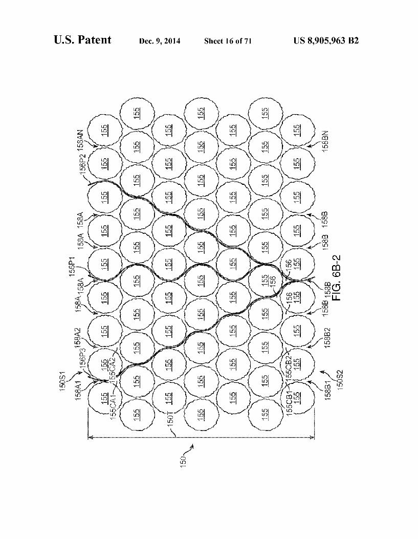
U.S. Patent Dec. 9, 2014 Sheet 25 Of 71 US 8,905,963 B2
7O.
703c-1
189DL- 39
FG. 7A-7A FG. 7A-7E.
U.S. Patent Dec. 9, 2014 Sheet 26 of 71 US 8,905,963 B2
FG 7A-8A FG. 7A-83

U.S. Patent Dec. 9, 2014 Sheet 27 Of 71 US 8,905,963 B2
3 W
FG. 7A-93

U.S. Patent Dec. 9, 2014 Sheet 28 of 71 US 8,905,963 B2
F.G. 7A. OB

U.S. Patent Dec. 9, 2014 Sheet 29 Of 71 US 8,905,963 B2
703SOB-1->
189B-1
FIG. 7A-11A FG 7A. B
U.S. Patent Dec. 9, 2014 Sheet 30 Of 71 US 8,905,963 B2
7 1/
- 8
-189BA 1.
5 - 89A
FG. 7A-2A

US 8,905,963 B2 Sheet 31 of 71 Dec. 9, 2014 U.S. Patent
N -189A
FG. 7A-13B
F.G. 7A-3A
FG 7A-3C

U.S. Patent Dec. 9, 2014 Sheet 32 Of 71 US 8,905,963 B2
FG 7A-4A

U.S. Patent Dec. 9, 2014 Sheet 33 Of 71 US 8,905,963 B2
v-1 - || || } ls
FG. A-5C2

U.S. Patent Dec. 9, 2014 Sheet 34 of 71 US 8,905,963 B2
100-1
FG 7A-7A FG. 7A-17B FG 7A-7C

U.S. Patent Dec. 9, 2014 Sheet 35 of 71 US 8,905,963 B2
6) 420N

U.S. Patent Dec. 9, 2014 Sheet 36 of 71 US 8,905,963 B2
FG 7B-6E1 FIG. 7B-6E2

U.S. Patent Dec. 9, 2014 Sheet 37 Of 71 US 8,905,963 B2
-1 EA / OA
FG. 7B-6- FG. 7B-6

U.S. Patent Dec. 9, 2014 Sheet 38 of 71 US 8,905,963 B2
FG. 7 C-1
1 SOS
160S 0 "S S{
G 7C - A FG. 7 C-13 FG. 7 C-1C
16OS

U.S. Patent Dec. 9, 2014 Sheet 39 Of 71 US 8,905,963 B2
FG. 7 C-2
79
Y
FG. 7 C-3

U.S. Patent Dec. 9, 2014 Sheet 40 of 71 US 8,905,963 B2
Y
F.G. 7 C-4A
10N

U.S. Patent Dec. 9, 2014 Sheet 41 of 71 US 8,905,963 B2
U.S. Patent Dec. 9, 2014 Sheet 42 of 71 US 8,905,963 B2
3G S.
1 an -2'- 1 to
N 120
ri- SO
()
130
FG. 8A

US 8,905,963 B2 U.S. Patent

U.S. Patent Dec. 9, 2014 Sheet 44 of 71 US 8,905,963 B2
FG. 8B

U.S. Patent Dec. 9, 2014 Sheet 45 of 71 US 8,905,963 B2

U.S. Patent Dec. 9, 2014 Sheet 46 of 71 US 8,905,963 B2

U.S. Patent Dec. 9, 2014 Sheet 47 of 71 US 8,905,963 B2

U.S. Patent Dec. 9, 2014 Sheet 48 of 71 US 8,905,963 B2
N-34
3
89.3
N189ABD FG. OA

U.S. Patent Dec. 9, 2014 Sheet 49 of 71 US 8,905,963 B2
316-1 FG. OB

U.S. Patent Dec. 9, 2014 Sheet 50 of 71 US 8,905,963 B2
N-703F.
- 400

U.S. Patent Dec. 9, 2014 Sheet 51 of 71 US 8,905,963 B2
FG 1 OD

US 8,905,963 B2 Sheet 52 of 71 Dec. 9, 2014 U.S. Patent
No.s:(50,

U.S. Patent Dec. 9, 2014 Sheet 53 of 71 US 8,905,963 B2
--189PH
FG. A

U.S. Patent Dec. 9, 2014 Sheet 54 Of 71 US 8,905,963 B2
Nort 150 F.G. 1 1 B

U.S. Patent Dec. 9, 2014 Sheet 55 of 71 US 8,905,963 B2
16
FIG 11C
U.S. Patent Dec. 9, 2014 Sheet 56 of 71 US 8,905,963 B2
On 7(2-
- C3S
N100 703FL-S
150 150
FG. 2A FG 123 F.G. 12C

U.S. Patent Dec. 9, 2014 Sheet 57 Of 71 US 8,905,963 B2
189A
50
FG. 3A

U.S. Patent Dec. 9, 2014 Sheet 58 Of 71 US 8,905,963 B2
N-189AFL in 15
702F-SA- NY roaFL
N-160 4.
ow
183
16
FG. 4A

US 8,905,963 B2 Sheet 59 of 71 Dec. 9, 2014 U.S. Patent

U.S. Patent Dec. 9, 2014 Sheet 60 of 71 US 8,905,963 B2
:

U.S. Patent Dec. 9, 2014 Sheet 61 of 71 US 8,905,963 B2
3.

U.S. Patent Dec. 9, 2014 Sheet 62 of 71 US 8,905,963 B2

U.S. Patent Dec. 9, 2014 Sheet 63 of 71 US 8,905,963 B2
< t o cN cC O wo N

U.S. Patent Dec. 9, 2014 Sheet 64 of 71 US 8,905,963 B2

US 8,905,963 B2 Sheet 65 Of 71 Dec. 9, 2014 U.S. Patent

US 8,905,963 B2 Sheet 66 of 71 Dec. 9, 2014 U.S. Patent

US 8,905,963 B2 U.S. Patent

U.S. Patent Dec. 9, 2014 Sheet 68 of 71 US 8,905,963 B2
O N
cy
s

U.S. Patent Dec. 9, 2014 Sheet 69 Of 71 US 8,905,963 B2
S. s O Š & co S
U.S. Patent Dec. 9, 2014 Sheet 70 of 71 US 8,905,963 B2

U.S. Patent Dec. 9, 2014 Sheet 71 Of 71 US 8,905,963 B2

US 8,905,963 B2 1.
NECTORAPPARATUS AND METHOD FOR DRUG DELIVERY
CROSS-REFERENCES TO RELATED APPLICATIONS
This application is a continuation of co-pending U.S. patent application Ser. No. 13/814,461, entitled “Injector Apparatus and Method For Drug Delivery,” filed Feb. 5, 2013: which in turn is a national stage entry of P.C.T. Application No. PCT/US1 1/46812, entitled “Injector Apparatus and Method For Drug Delivery filed Aug. 5, 2011; that in turn claims priority to the following U.S. Patent Applications: U.S. Patent App. Ser. 61/371,154, entitled "Injector Appara tus and Method For Drug Delivery,” filed Aug. 5, 2010; U.S. Patent App. Ser. No. 61/499,095, entitled “Injector Apparatus and Method for Drug Delivery,” filed Jun. 20, 2011; U.S. Patent App. Ser. No. 61/501,021, entitled “Injector Apparatus and Method for Drug Delivery,” filed: Jun. 24, 2011; U.S. Patent App. Ser. No. 61/504,038, entitled “Injector Apparatus and Method for Drug Delivery,” filed Jul. 1, 2011; U.S. Patent App. Ser. 61/371,169, entitled “Implantable Therapeutic Device.” filed on Aug. 5, 2010; U.S. Patent App. Ser. No. 61/495,251, entitled “Diagnostic Methods and Apparatus.” filed Jun. 9, 2011; and U.S. Patent App. Ser. No. 61/495,718, entitled “Diagnostic Methods and Apparatus' filed, Jun. 10, 2011, the full disclosures of which are incorporated herein by reference.
BACKGROUND
The present invention is generally directed to devices implanted in the body and apparatus to replace a fluid of the implanted device with a therapeutic fluid. The prior methods and apparatus for treating diseases of
the eye can be less than ideal in at least Some instances. For example, eye drops may have limited penetration of the exter nal tissue of the eye. Such that at least some therapeutic agents may not be delivered effectively with eye drops in at least Some instances, for example high molecular weight therapeu tic agents. Further, drops administered to the eye may not remain in the tear of the eye as long as would be ideal and can be washed away, for example when the patient blinks so as to provide less than ideal therapeutic benefit in at least some instance.
Implantable devices have been proposed to deliver treat ment to the eye. However, in at least some instances, the therapeutic agent of the implantable device can be depleted, and the device may be removed or additional therapeutic agent placed in the device.
Prior methods and apparatus to place a therapeutic fluid in a device implanted in the eye can provide less than ideal results in at least some instances. For example, the amount of therapeutic agent placed in the device may be less than ideal in at least Some instances. Further at least Some of the prior methods to place of a therapeutic fluid in a device implanted in an eye may take longer than would be ideal. In at least some instances, the fluid placed initial in the device may be forced out of the therapeutic device, such that the amount of thera peutic agent placed in the treatment device can be less than ideal for Sustained release of the therapeutic agent. Work in relation to embodiment of the present invention
also suggests that at least some prior injection apparatus may result in leakage during injection of the therapeutic agent. In at least Some instances the injected fluid may comprise amounts of therapeutic agent that may be not be suitable for
10
15
25
30
35
40
45
50
55
60
65
2 direct contact with tissue. Such that leakage, or potential leakage, may limit available treatment options.
In light of the above, it would be desirable to provide improved methods and apparatus to place atherapeutic agent in a device implanted in the eye to provide improved treat ments of diseases of the eye.
SUMMARY
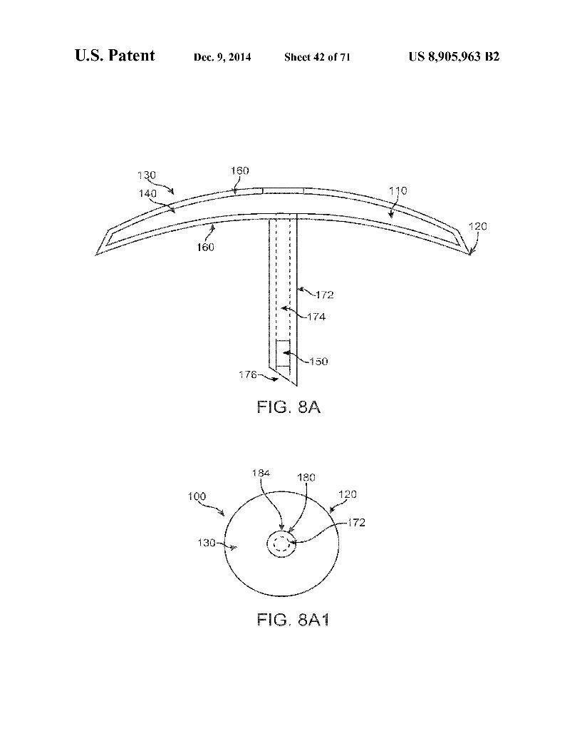
Embodiments of the present invention provide improved methods and apparatus to provide a therapeutic fluid to devices implanted in the body, for example to containers of devices implanted in the eye of a patient. The methods and apparatus may comprise an injector to increase an amount of therapeutic agent injected into the device implanted in the eye, or a structure to receive the therapeutic fluid within the device implanted in the eye, or combinations thereof. The device implanted in the eye may comprise a reservoir cham ber coupled to a porous structure so as to release the thera peutic agent for an extended time. In many embodiments, the volume of the reservoir chamber is sized to fit within the eye without substantially affecting vision. The porous structure may have a high resistance to flow, and in many embodiments the therapeutic fluid injected into the device may be exchanged with a fluid of the device implanted in the eye.
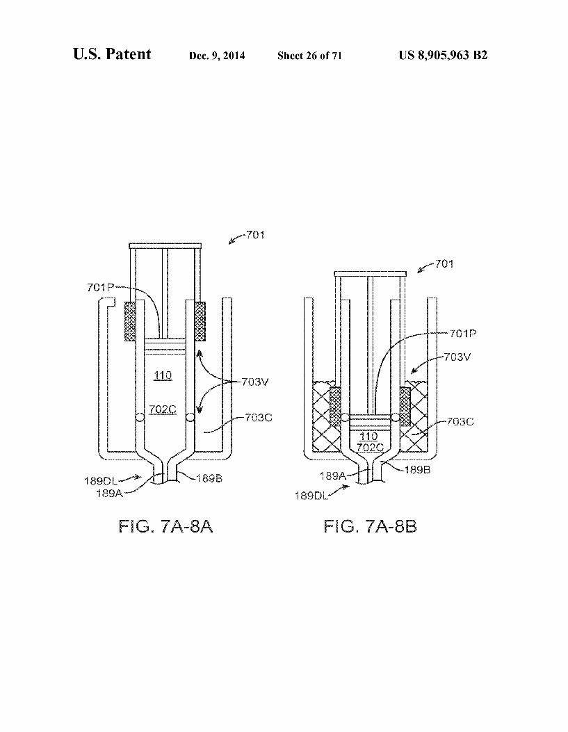
In many embodiments, the container implanted in the eye comprises a fluid having a density different than the fluid therapeutic fluid of the container implanted in the body. The therapeutic fluid may comprise a formulation of a therapeutic agent having a density greater than a fluid of the device implanted in the eye, such that the therapeutic formulation injected into the implanted chamber may separate at least partially. In many embodiments, the at least partial separation of the therapeutic fluid from the fluid of the implanted device can be used to improve an efficiency of exchange of the therapeutic fluid with the fluid of the chamber, so as to increase the amount of therapeutic fluid in the chamber. While the methods and apparatus as described herein can be used with many devices to increase the amount of therapeutic fluid in the implanted device, the increased the efficiency can be especially beneficial with implanted devices having a res ervoir chamber comprising a substantially constant Volume. Also, with implants located at least partially in the vitreous humor of the eye, the size of the reservoir chamber can some what limited to provide a clear optical path for vision, and the embodiments described herein can be used to increase the amount of fluid placed in the chamber So as to increase the therapeutic benefit of the implanted device and provide sus tained release for an extended time.
In many embodiments, one or more of the therapeutic device or the injector can be configured to increase the amount of therapeutic fluid placed in the device based on the at least partial separation. The injector may comprise a first channel sized to extend to a first opening at a first location of the implanted device reservoir chamber so as to pass the therapeutic fluid into the chamber, and a second channel can be sized to extend to a second opening at a second location of the implanted device chamber so receive the fluid of the implanted device, such that the efficiency of the exchange can be increased based on the at least partial separation and the separation of the first location and the second location. The first channel may comprise a first lumen of at least one needle, and the second channel can be sized and shaped in many ways and may comprise a second lumen of the at least one needle. The second opening may comprise a vent to receive fluid from the chamber of the therapeutic device and inhibit excessive
US 8,905,963 B2 3
pressurization of the reservoir chamber so as to maintain substantially the integrity and function of the therapeutic device implanted in the eye.
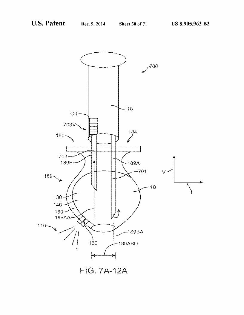
In many embodiments, the injector comprises a stop coupled to the at least one needle. The first opening can be located a first distance from the stop and the second opening can be located a second distance from the stop. Such that the first opening and the second opening are placed at locations of the implanted device so as to increase the at least partial separation when the stop engages a tissue surface Such as the conjunctiva. In many embodiments, the therapeutic fluid can be denser than the fluid of the implanted device and, and the first opening to inject the therapeutic fluid may be located below the second opening when placed in the reservoir cham ber, such that the denser therapeutic fluid can be placed in the reservoir chamber below the less dense fluid of the reservoir chamber so as to enhance the at least partial separation. The stop may comprise a soft material. Such as an elas
tomer. The soft material may form a seal when placed against a tissue Surface Such as the conjunctiva, and can maintain integrity of the conjunctival epithelium when the seal engages the conjunctiva. The sealing can decrease leakage of the therapeutic fluid, which can be helpful to increase an amount of fluid placed in the reservoir chamber of the therapeutic device. The sealing of the Soft stop engaging the conjunctiva may also decrease interaction of the therapeutic fluid with the conjunctiva, which can be beneficial when the therapeutic fluid comprises a concentration or amount of therapeutic agent that may have a potentially undesirable interaction with the conjunctiva, for example with an antineoplastic therapeu tic agent.
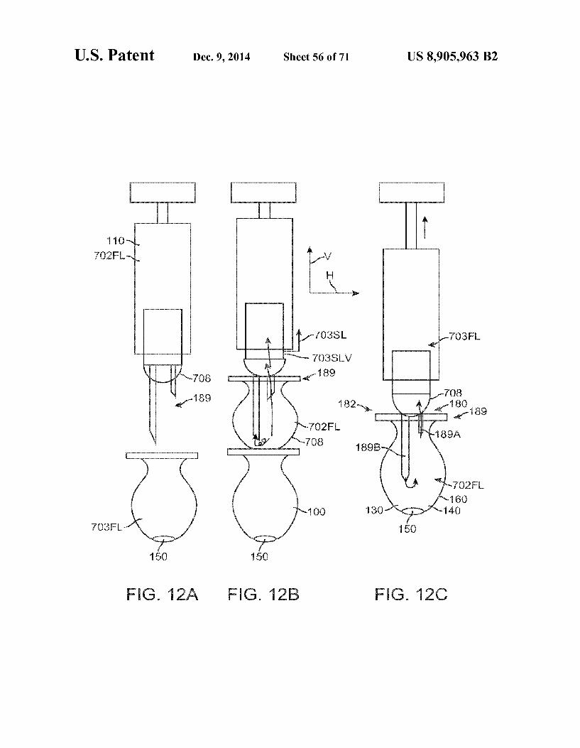
In many embodiments, the injector can be configured to pass a bolus of therapeutic fluid through the porous structure of the therapeutic device. The injector may comprise a valve that closes to push therapeutic fluid through the porous struc ture of the implanted device. The valve may comprise one or more of a mechanism, a porous structure, or a resistance to flow to pass the therapeutic fluid through the porous structure. The mechanism may comprise one or more movable compo nents such as a slider, a piston, a sleeve or a deflectable component. The porous structure may comprise a porous material having resistance to flow that increase Substantially when the displaced fluid of the implanted device contacts the porous structure. The resistance to flow may correspond to a restriction or other structure along the outflow path of the second channel. The resistance to flow can be sufficient so as to encourage the therapeutic fluid to pass through the thera peutic structure. The structure corresponding to the resistance to flow along the outflow path may comprise a lumen coupled to a vent placed in the therapeutic device.
In many embodiments, the injector comprises a flow rate to provide the at least partial separation.
In many embodiments, one or more of the therapeutic device or the injector can be configured to mix the therapeutic fluid with the implanted device fluid when the therapeutic fluid is injected so as to increase the amount of therapeutic fluid in the chamber. In many embodiments, the injector is configured to inject the therapeutic fluid at a rate of no more than about 100LL per second, for example, and one or more of the injector or the implanted comprises structures to mix the therapeutic fluid with the fluid of the implanted device at the flow rate capable of providing the at least partial separa tion.
In a first aspect, embodiments of the present invention provide an apparatus to treat a patient. The apparatus com prises an injector to inject atherapeutic fluid into a chamber of a therapeutic device implantable in the patient with at least
10
15
25
30
35
40
45
50
55
60
65
4 partial separation of a fluid of the implantable therapeutic device from the therapeutic fluid.
In another aspect, embodiments of the present invention provide an apparatus to treat an eye. The apparatus comprises an injector to inject a therapeutic fluid into a chamber of a therapeutic device implantable in the eye with at least partial separation of a fluid of the implantable therapeutic device from the therapeutic fluid.
In many embodiments, the therapeutic fluid comprises a therapeutic fluid density different from a density of the fluid of the implantable therapeutic device so as to provide the at least partial separation.
In many embodiments, the fluid of the implantable thera peutic device comprises a density different from the thera peutic fluid density. The therapeutic fluid density may differ from the density of the implantable device fluid by at least about 1% So as to provide the at least partial separation, for example by at least about 2% so as to provide the at least partial separation. The therapeutic fluid density may differ from the density of the implantable device fluid by at least about 3% so as to provide the at least partial separation. The therapeutic fluid density may differs from the density of the implantable device fluid by no more than about 30% so as to provide the at least partial separation, for example by no more than about 20% so as to provide the at least partial separation. In many embodiments, the therapeutic fluid density differs from the density of the implantable device fluid by no more than about 10% so as to provide the at least partial separation.
In many embodiments, a difference of the therapeutic fluid density relative to the density of the implantable device fluid is within a range from about 1% to about 30% so as to provide the at least partial separation, for example within a range from about 2% to about 20% so as to provide the at least partial separation. The difference of the therapeutic fluid density relative to the density of the implantable device fluid can be within a range from about 3% to about 10% so as to provide the at least partial separation.
In many embodiments, the injector comprises at least one needle comprising a first lumen to pass the therapeutic fluid into the therapeutic device and a second lumen to receive the therapeutic fluid from the chamber, and the injector is con figured to inject the therapeutic fluid at a flow rate so as to inhibit mixing of the therapeutic fluid with the implantable device fluid such that the second lumen receives a portion of the device fluid substantially separated from the therapeutic fluid.
In many embodiments, the injector is configured to inject the therapeutic agentata flow rate so as to provide the at least partial separation. The at least partial separation can be based on a therapeutic fluid density different from a therapeutic fluid density.
In many embodiments, the chamber has a Substantially constant Volume. The Substantially constant Volume can be within a range from about 1 uL to about 100LL or more. The Substantially constant Volume can be within a range from a range from about 15uL to about 75ul, for example within a range from about 25ul to about 75uL.
In many embodiments, the injector is configured to inject the therapeutic fluid into the chamber over a period of time. The time can be within a range from about 1 second to about 30 seconds, for example within a range from about 2 seconds to about 8 seconds.
In many embodiments, the injector comprises one or more ofa structure resistant to flow, a restriction, a porous structure, a sintered porous structure, or a mechanism to inject the agent at the rate Sufficient to provide the at least partial separation.

US 8,905,963 B2 5
The mechanism comprises one or more of a spring, a gas, or a liquid to inject the liquid at the rate.
In many embodiments, the implantable device comprises a porous structure to release the therapeutic agent. The porous structure has a resistance to flow, and the injector structure resistant to flow comprises a resistance to flow proportional to the resistance to flow of the porous structure, such that a portion of the therapeutic fluid passes through the porous Structure.
In many embodiments, the implant fluid comprises a remaining portion of a first therapeutic fluid placed in the therapeutic device for at least about one week, and the thera peutic fluid is similar to the first therapeutic fluid.
In many embodiments, the fluid of the implantable device comprises a remaining portion of a first amount of first thera peutic agent of a first therapeutic fluid placed in the therapeu tic device and components of the vitreous humor of the eye. The remaining portion of the first therapeutic fluid placed in the implantable device may comprise a remaining amount of the therapeutic agent. The remaining amount of the therapeu tic agent corresponds to no more than about half of a first amount of the first therapeutic agent so as to provide the density difference. The remaining portion may comprise a remaining stabilizer, and an amount of the remaining stabi lizer may correspond to no more than about half of a first amount of the stabilizer of the first therapeutic fluid so as to provide the density difference.
In many embodiments, one or more components of the vitreous humor correspond to the density of the fluid of the implantable therapeutic device less than the therapeutic fluid therapeutic fluid density so as to provide the at least partial separation.
In many embodiments, the therapeutic fluid density is within a range. The range can be from about 0.5 g/cm3 to about 2 g/cm3 and the implantable device density is within a range from about 0.5 to about 2 g/cm, for example within a range from about 1.01 to about 1.5 g/cm. The therapeutic fluid density can be within a range from about 1.03 to about 1.5 g/cm.
In many embodiments, the injector comprises at least one needle having at least one lumen to couple the chamber to a Syringe comprising the therapeutic agent. The at least one lumen may comprise a first lumento pass the therapeutic fluid into the implantable device and a second lumen to receive liquid from the implantable therapeutic device. The first lumen may extend to a first opening and the second lumen may extend to a second opening, in which the first opening is spaced apart from the second opening so as to encourage the at least partial separation. The first opening can be located distal to the second opening, Such that the therapeutic fluid is passed to a distal portion of the chamber and the fluid of the implantable therapeutic device is received with the proximal portion of the chamber to encourage the at least partial sepa ration.
In many embodiments, a container receives the fluid of the therapeutic device received through the second lumen, and the container comprises a vent to pass air displaced from the container. The vent can be fluidicly coupled to the second opening so as to define a flow path extending from the open ing to the vent.
In many embodiments, the flow path comprises a resis tance to flow so as to encourage the at least partial separation. The flow path may comprises one or more structures to inhibit flow of the fluid of the therapeutic device, the one or more structures comprising one or more of a size of the second opening, a restriction along the flow path or a porous structure along the flow path.
10
15
25
30
35
40
45
50
55
60
65
6 In many embodiments, the injector porous structure com
prises a plurality of interconnecting channels located along the flow path on a downstream portion of the container. The injector porous structure comprises a resistance to liquid flow greater than a porous structure of the implantable device Such that the therapeutic fluid is passed through the porous struc ture of the implantable device when the fluid of the implant able device contacts the injector porous structure located along the flow path on the downstream portion of the con tainer.
In many embodiments, the second lumen is coupled to a vent and the vent comprises a resistance to flow to pressurize the chamber and pass a portion of the therapeutic fluid through the porous structure when the fluid of the implantable device passes through the vent.
In many embodiments, the injector comprises a cartridge comprising the at least one needle to couple to the Syringe. The cartridge may comprise a vent having a resistance to flow Sufficient to encourage the at least partial separation of the therapeutic agent fluid from the fluid of the implantable device.
In many embodiments, the at least one lumen comprises a first lumen to pass the therapeutic fluid into the implantable device and a second lumento receive liquid from the implant able therapeutic device.
In many embodiments, the at least one needle comprises a first needle and a second needle.
In many embodiments, the at least one needle comprises a first needle having a first lumen extending along a first axis and a second needle having a second lumen extending along a second axis, and the first axis is separated from the second axis so as to increase the at least partial separation of the therapeutic fluid from the implantable device fluid.
In many embodiments, the at least one needle comprises a double lumen needle having a first needle having a first lumen extending along a first axis and a second needle having a second lumen extending along the first needle Such that the second needle is substantially concentric with the first axis.
In many embodiments, the at least one needle comprises an axis extending along an elongate dimension of the at least one needle and wherein the at least partial separation corresponds to an angle of the axis away from horizontal when the thera peutic formulation is injected. The at least partial separation may correspond to an increase of at least about one percent of an amount of therapeutic fluid placed in the therapeutic device when the angle away from horizontal comprises at least about 10 degrees. The at least partial separation may correspond to an increase of at least about two percent of an amount of therapeutic fluid placed in the therapeutic device when the angle away from horizontal comprises at least about 35 degrees.
In many embodiments, the injector is configured to inject the therapeutic fluid with the at least partial separation such that a 1 percent increase in density of the therapeutic fluid relative to the density of the chamber fluid corresponds to at least about a 1 percent increase of the amount of therapeutic fluid placed in the chamber.
In many embodiments, the injector is configured to inject the therapeutic fluid with the at least partial separation such that a 1 percent increase in density of the therapeutic fluid relative to the density of the chamber fluid corresponds to at least about a 2 percent increase of the amount of therapeutic fluid placed in the chamber with an injection of the therapeu tic fluid into the container.
In many embodiments, the injector is configured to inject the therapeutic fluid with the at least partial separation such that a 3 percent increase in density of the therapeutic fluid

US 8,905,963 B2 7
relative to the density of the chamber fluid corresponds to at least about a 4 percent increase of the amount of therapeutic fluid placed in the chamber with an injection of the therapeu tic fluid into the container.
In many embodiments, the at least about 1 percent increase of the amount of therapeutic fluid placed in the chamber corresponds to an angle of injection away from horizontal. The angle of injection away from horizontal corresponds to at least about 10 degrees away from horizontal, and may corre spond to at least about 15 degrees away from horizontal.
In many embodiments, the fluid of the implantable device comprises a liquid composed of water, components of the vitreous humor of the eye, and the therapeutic agent. The fluid of the implantable device may comprise a stabilizer.
In many embodiments, the therapeutic fluid comprises a liquid composed of water and the therapeutic agent. The therapeutic fluid may comprise a stabilizer.
In many embodiments, the fluid of the implantable device is displaced at a rate within a range from about 1 u, per second to about 200 uL per second. The fluid of the implant able device can be displaced at a rate within a range from about 2 LL per second to about 100 u, per second, for example from about 5 uL per second to about 50 uL per second.
In many embodiments, the fluid of the implantable device is displaced with an efficiency of at least about 70%. The fluid of the implantable device can be displaced with an efficiency of at least about 80%, for example at least about 90%.
In many embodiments, the valve comprises one or more of a float valve coupled to an opening or a hard stop coupled to a piston.
In many embodiments, the injector comprises a cartridge comprising the at least one needle to couple to the Syringe.
In another aspect, embodiments of the present invention provide apparatus to treat an eye. The apparatus comprises a cartridge to inject a therapeutic fluid into a chamber of a therapeutic device implantable in the eye with at least partial separation of a fluid of the implantable therapeutic device from the therapeutic fluid.
In many embodiments, the cartridge comprises a connector to couple to a syringe, a vent and at least one needle. The at least one needle comprising a first lumen and a second lumen, the first lumen sized to extend from the connector into the chamber to pass the therapeutic fluid from the Syringe, the second lumen comprising the vent and sized to place the vent in the chamber and extend to a collection container so as to receive the fluid of the implantable therapeutic device with the collection container, wherein cartridge is adapted to the density of the therapeutic fluid so as to provide a refill effi ciency of the chamber of at least about 70%.
In many embodiments, the vent comprises a resistance to flow corresponding to a resistance to flow of a porous struc ture of the implantable device to pass an amount of the thera peutic fluid through the porous structure when the therapeutic device fluid is displaced.
In many embodiments, the resistance to flow of the vent structure is proportional to the resistance to flow of the porous structure so as to pass the amount of the therapeutic fluid through the porous structure.
In many embodiments, the resistance to flow of the vent structure is substantially greater than to the resistance to flow of the porous structure so as to pass the amount of the thera peutic fluid through the porous structure. The vent structure may comprise a channel sized to provide a Substantial portion of the resistance to flow of the vent structure. The vent struc ture may comprise a porous material to provide a substantial portion of the resistance to flow of the vent structure.
10
15
25
30
35
40
45
50
55
60
65
8 In many embodiments, the at least one needle comprises a
first needle and the second needle. In many embodiments, the at least one needle comprises a
double lumen needle. In another aspect embodiments provide, apparatus to treat
a patient. An implantable device comprises a chamber and a penetrable barrier coupled to a porous structure. The device is capable of receiving a pressure of at least about 50 PSI to the chamber and the porous structure without rupturing.
In many embodiments, the device is capable of receiving a pressure of at least about 100 PSI to the chamber, the pen etrable barrier and the porous structure without rupturing.
In many embodiments, the device is capable of receiving a pressure of at least about 200 PSI to the chamber, the pen etrable barrier and the porous structure without rupturing.
In another aspect, embodiments provide an apparatus to treat a patient. An implantable device comprises a chamber and a penetrable barrier coupled to a porous structure. The chamber comprises a proximal end and a distal end. The porous structure is located away from the distal of the cham ber in increase an amount of therapeutic fluid placed in the chamber with one or more of injection or aspiration.
In another aspect, embodiments provide an apparatus to treat a patient. The apparatus comprises a therapeutic device comprising a reservoir chamber and a fluid separator within the reservoir chamber of the device to separate a therapeutic fluid injected into the device from a fluid of the implantable device.
In many embodiments, the fluid separator comprises one or more of movable fluid separator or a container within the reservoir chamber of the therapeutic device.
In another aspect, embodiments provide an apparatus. The apparatus comprises an injector configured to inject air into a chamber of a device implantable in the eye to replace a fluid of the device with a therapeutic fluid.
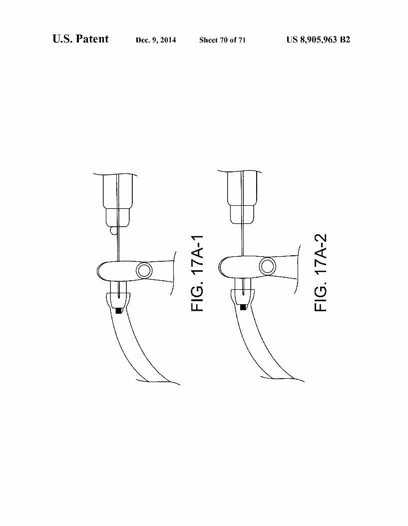
In another aspect, embodiments provide an apparatus to treat a patient. An injector device comprises a needle and a stop. The needle comprises a tip. An implantable device com prises a chamber and a penetrable barrier coupled to a porous structure. A structure to divert flow of a therapeutic fluid is located within the chamber. The stop is configured to position the tip of the needle within the chamber with a gap extending the between the tip and the structure when the stop contacts a conjunctiva of the eye.
In another aspect, embodiments provide apparatus to treat an eye. A connector to couple to a container having a thera peutic fluid comprises therapeutic agent to treat the eye. At least one needle comprises a first lumen to pass the therapeu tic fluid and a second lumen to receive the fluid from the therapeutic device. The first lumen extends to a first opening, and the second lumen extends to a second opening. A con tainer receives a fluid form a therapeutic device implantable in the eye. The second lumen is fluidicly coupled to the container so as to define a flow path extending from the second opening to the container. The flow path comprises a resistance So as to at least partially separate the therapeutic fluid from the fluid of the implantable device when the thera peutic fluid displaces the fluid of the implantable device.
In another aspect, embodiments provide an apparatus to treat an eye with a therapeutic agent. At least one needle comprises a lumen extending to an opening to inject a thera peutic fluid comprising the therapeutic agent into a chamber of a therapeutic device implantable in the eye. A vent struc ture is configured to receive a fluid of the therapeutic device. The vent structure comprises a resistance to flow of the fluid of the therapeutic device.

US 8,905,963 B2
In many embodiments, the resistance to flow of the vent structure corresponds to a resistance to flow of a porous structure of the therapeutic device so as to pass an amount of the therapeutic fluid through the porous structure.
In many embodiments, the amount comprises at least about 0.1 percent of an injection amount into the therapeutic device.
In many embodiments, the vent structure comprises a vent and a channel coupled to the vent so as to provide the resis tance to flow of the vent structure.
In many embodiments, the apparatus further comprises a stop, in which the stop comprises a lower Surface to engage a conjunctiva of the eye. The at least one needle extends a distance along an axis from the lower Surface to the opening, and the distance is dimensioned to place the opening and the vent in the reservoir chamber when the lower Surface engages the conjunctiva.
In many embodiments, the apparatus further comprises a cartridge, and the cartridge comprises the at least one needle and the vent structure. The cartridge comprises a connector to couple to a syringe, and the at least one needle comprises a first lumen and a second lumen. The first lumen can be sized to extend from the connector into the chamber to pass the therapeutic fluid from the Syringe, and the second lumen may extend to the vent and be sized so as to place the vent in the chamber and extend to a collection container so as to receive the fluid of the implantable therapeutic device with the col lection container. The cartridge can be adapted to the density of the therapeutic fluid so as to provide a refill efficiency of the chamber of at least about 70%.
In many embodiments, the resistance to flow of the vent structure is substantially greater than the resistance to flow of the porous structure of the implantable device so as to pass the amount of the therapeutic fluid through the porous structure.
In many embodiments, the resistance to flow of the vent structure is substantially less than the resistance to flow of the porous structure of the implantable device so as to pass the amount of the therapeutic fluid through the porous structure.
In many embodiments, the at least one needle comprises a first needle and the second needle.
In many embodiments, the at least one needle comprises a double lumen needle.
In another aspect, embodiments provide method of treating a patient with an implantable device. A therapeutic fluid is injected into a chamber of a therapeutic device implanted in the patient, Such that the therapeutic fluid entering the cham ber is at least partially separated from a fluid of the chamber.
In another aspect, embodiments provide method of treating an eye. A therapeutic fluid is injected into a chamber of a therapeutic device implanted in the eye, such that the thera peutic fluid entering the chamber is at least partially separated from a fluid of the chamber.
In many embodiments, the therapeutic fluid comprises a density and the fluid of the device comprises a density differ ent from the density of the therapeutic fluid.
In many embodiments, the therapeutic device comprises a penetrable barrier on a proximal end and a porous structure on a distal end with an axis extending between the penetrable barrier and porous structure and wherein the axis is oriented away from horizontal to provide the at least partial separation. The patient can be positioned Such that the porous structure is located above the penetrable barrier.
In many embodiments, the patient is reclined in a chair with a tilted head such that the porous structure is located above the penetrable barrier when the implanted device is located in the pars plana region of the eye.
In many embodiments, the patient is positioned such that the porous structure is located below the penetrable barrier.
10
15
25
30
35
40
45
50
55
60
65
10 In many embodiments, the therapeutic fluid is injected
upward to at least partially separate the therapeutic fluid from the fluid of the implanted therapeutic device.
In many embodiments, the therapeutic fluid is injected downward to at least partially separate the therapeutic fluid from the fluid of the implanted therapeutic device.
In many embodiments, at least one needle is advanced through a penetrable barrier of the implanted device such that a first opening of the at least one needle is placed at a distal portion of the chamber and a second opening of the at least one needle is placed at a proximal portion of the chamber Such that the first opening is located below the second opening and wherein the therapeutic fluid comprises a density greater than the implanted device fluid and is passed through the first opening below the second opening so as to at least partially separate the therapeutic fluid from the therapeutic device fluid within the chamber.
In many embodiments, the therapeutic fluid is injected with the at least partial separation Such that a percent change in density of the therapeutic fluid corresponds to a percent change in fill efficiency of the chamber greater than the per cent change in density of the therapeutic fluid.
In another aspect, embodiments provide a method of treat ing an eye. Air is injected into a chamber of a therapeutic device implanted in the eye to at least partially replace a fluid of the implanted device with a therapeutic fluid.
In another aspect, embodiments provide an apparatus to inject a therapeutic agent into a patient. The apparatus com prises at least one needle capable of penetrating an external tissue of the patient and extending to a depth within the patient and one or more chambers to hold atherapeutic agent coupled to the at least one needle. A deformable indicator extends at least partially around the at least one needle to indicate needle penetration of the needle to the depth.
In many embodiments, the deformable visual indicator comprises a first configuration having a first cross sectional width prior to contact with the tissue and a second configu ration having a second cross sectional width, in which the second cross sectional width is greater than the first cross sectional width to indicate the needle at the depth with increased visibility of the visual indicator.
In many embodiments, the at least one needle is Supported with an annular Support structure having a distance across and wherein the deformable visual indicator comprises an annular deformable structure extending around the at least one needle, and the first cross sectional width is less than the distance across and the second cross sectional widthis greater than the distance across.
In many embodiments, the deformable visual indicator comprises a modulus to resist deformation to indicate the needle inserted to the depth with a force to maintain the at least one needle at the depth.
In many embodiments, the deformable visual indicator visible comprises a visible color to indicate the needle at the depth to the user.
In many embodiments, the at least one needle comprises a first lumen extending from the visual indicator to a first open ing located first distance from the visual indicator and a second lumen extending from the visual indicator to a second opening located a second distance from the visual indicated and wherein visual indicator indicates the first opening at a first depth and the second opening at a second depth.
In many embodiments, the at least one needle comprises a silicon needle having a gauge of at least about 25.
In many embodiments, the deformable visual indicator comprises a Shore A hardness within a range from about 5 to

US 8,905,963 B2 11
about 30 to indicate the needle inserted to the depth with a force to maintain the at least one needle at the depth.
In many embodiments, the apparatus further comprises an implantable therapeutic device, the implantable therapeutic device having a reservoir chamber to hold a quantity of thera peutic agent, the reservoir chamber extending along an axis of the therapeutic device, and wherein the at least one needle has an lumen extending to opening separated from the deform able visual indicator Such that the opening is located in the reservoir chamber when the visual indicator is deformed to indicate the needle positioned at the distance.
In many embodiments, the implantable therapeutic device comprises a porous structure to release therapeutic amounts of the therapeutic agent for an extended time. The porous structure may comprise a release rate index of no more than about 0.5 to release the therapeutic agent for an extended time of at least about one month.
In many embodiments, the opening is positioned in a proxi mal half of the reservoir chamber when the visual indicator is deformed.
In many embodiments, the opening is positioned in a distal half of the reservoir chamber when the visual indicator is deformed.
In another aspect, embodiments provide a method of treat ing a patient having a tissue. At least one needle is advanced into the tissue such that a deformable visual indicator couples to the tissue and deforms to indicate the at least one needle at a depth. A therapeutic agent is injected from one or more chambers coupled to the at least one needle such that the therapeutic agent is injected through a lumen of the at least one needle at the depth when the visual indicator is deformed.
In many embodiments, the deformable visual indicator comprises a first configuration having a first cross sectional width prior to contact with the tissue and a second configu ration having a second cross sectional width when the indi cator is coupled to the external penetrable tissue, in which the second cross sectional width is greater than the first cross sectional width to indicate the needle at the depth with increased visibility of the visual indicator.
In many embodiments, the apparatus further comprises an implantable therapeutic device. The implantable therapeutic device has a reservoir chamber to hold a quantity of thera peutic agent. The reservoir chamber has a thickness and a width sized for placement between the conjunctiva and the Sclera, and wherein the at least one needle has an lumen extending to opening separated from the deformable visual indicator Such that the opening is located in the reservoir chamber when the visual indicator is deformed to indicate the needle positioned at the distance.
BRIEF DESCRIPTION OF THE DRAWINGS
FIG. 1 shows an eye suitable for incorporation of the thera peutic device, in accordance with embodiments of the present invention;
FIG. 1A-1 shows a therapeutic device implanted at least partially within the sclera of the eye as in FIG. 1;
FIGS. 1A-1-1 and 1A-1-2 show a therapeutic device implanted under the conjunctiva and extending through the Sclerato release atherapeutic agent into vitreous humor of the eye so as to treat the retina of the, in accordance with embodi ments of the present invention;
FIG. 1A-2 shows structures of a therapeutic device config ured for placement in an eye as in FIGS. 1A-1 and 1A-1-1, according to embodiments of the present invention;
FIG. 1A-2-1 shows a therapeutic device loaded into an insertion cannula, in which the device comprises an elongate
5
10
15
25
30
35
40
45
50
55
60
65
12 narrow shape for insertion into the Sclera, and in which the device is configured to expand to a second elongate wide shape for retention at least partially in the Sclera;
FIG. 1A-2-2 shows a therapeutic device comprising a res ervoir Suitable for loading in a cannula:
FIG. 1B shows a therapeutic device configured for place ment in an eye as in FIGS. 1A-1 and 1A-1-1, in accordance with embodiments of the present invention;
FIG. 1C shows a therapeutic device configured for place ment in an eye as in FIGS. 1A-1 and 1A-1-1, in accordance with embodiments of the present invention;
FIG. 1C-A shows at least one exit port, according to embodiments of the present invention:
FIG.1C-1 shows a method of removing a binding material, according to embodiments of the present invention;
FIG.1C-2 and inserting the therapeutic agent with a second insert having the TA bound thereon;
FIG. 1C-3 shows syringe being filled with a commercially available formulation of therapeutic agent for injection into the therapeutic device, in accordance with embodiments;
FIG. 1D shows a therapeutic device configured for place ment in an eye as in FIG. 1A-1 and IA-1-1, in which the device comprises a plurality of chambers and channels con necting the chambers so as to linearize the release of the therapeutic agent;
FIG. 1E shows a therapeutic device configured for place ment in an eye as in FIGS. 1A-1 and 1A-1-1, in which the device comprises a needle stop located at the bottom of the therapeutic device;
FIG.1E-1 shows atherapeutic device configured for place ment in an eye as in FIGS. 1A-1 and 1A-1-1, in which the device comprises a needle stop located at the bottom of the therapeutic device and the shape of the device encourages the movement of the therapeutic agent within the chamber of the therapeutic device;
FIG.1E-2 shows atherapeutic device configured for place ment in an eye as in FIGS. 1A-1 and 1A-1-1, in which the device comprises a needle stop located in the middle of the therapeutic device;
FIG. 1 E-3 shows atherapeutic device configured for place ment in an eye as in FIGS. 1A-1 and 1A-1-1, in which the device comprises a needle stop located in the middle of the therapeutic device and the shape of the device encourages the movement of the therapeutic agent within the chamber of the therapeutic device;
FIG. 1 E-3-1 shows a top view of the therapeutic device configured for placement in an eye as in FIGS. 1 E-3;
FIG. 1 F-1 shows a therapeutic device comprising a flow diverter, in accordance with embodiments of the present invention;
FIG. 1 F-2 shows a therapeutic device comprising a fluid separator having Sufficient Volume so as to retain at least a portion of the therapeutic fluid, such that at least a portion of the implanted device fluid is urged through the porous struc ture with at least partial separation, in accordance with embodiments of the present invention:
FIG. 1F-3 shows a therapeutic device comprising a fluid separator having Sufficient Volume so as to retain at least a portion of the therapeutic fluid, such that at least a portion of the implanted device fluid 703FL is urged through the porous structure with at least partial separation, in accordance with embodiments of the present invention:
FIG. 1G shows a therapeutic device comprising porous structure located away from a distal end and axis, Such that therapeutic fluid settles toward the distal end and the
US 8,905,963 B2 13
implanted fluid is passed through the porous structure with at least partial separation, in accordance with embodiments of the present invention;
FIG. 1H shows a therapeutic device comprising a fluid separator, in which the fluid separator is configured to move distally with injection of therapeutic fluid so as to separate the fluids during injection, in accordance with embodiments of the present invention;
FIG. 1I shows a therapeutic device comprising a plurality of beads so as to mix the fluids during injection and inhibit separation Such that device fluid is passed through porous structure, in accordance with embodiments of the present invention;
FIG. 2 shows an access port suitable for incorporation with the therapeutic device, in accordance with embodiments of the present invention;
FIG. 3A shows a collar suitable for incorporation with the therapeutic device, in accordance with embodiments of the present invention;
FIG. 3B shows biocompatible material impregnated with an anti-bacterial agent on the therapeutic device to inhibit bacterial growth along the device from the sclera to the vit reous humor;
FIG. 4A shows released fragments of antibodies, and FIG. 4B shows antibody fragments reversibly bound to a substrate, in accordance with embodiments of the present invention;
FIG. 5A shows a therapeutic device coupled to an injector to insert therapeutic agent into the device;
FIG. 5A-1 shows a therapeutic device coupled to an injec tor to simultaneously inject and remove material from the device;
FIG. 5B shows a therapeutic device comprising a micro loop channel;
FIG. 5C-1 shows a therapeutic device comprising a tortu ous channel;
FIG.5C-2 shows a therapeutic device comprising a coiled channel; FIG.5D shows an expandable and contractible structure to
retain the therapeutic agent and an outer rigid casing to couple to the sclera;
FIG.5E shows a membrane disposed over an exit port of a therapeutic device;
FIG. 5F shows a therapeutic device comprising a tubular membrane clamped onto the therapeutic device;
FIG. 6A-1 shows a therapeutic device comprising a con tainer having a penetrable barrier disposed on a first end, a porous structure disposed on a second end to release thera peutic agent for an extended period, and a retention structure comprising an extension protruding outward from the con tainer to couple to the Sclera and the conjunctiva;
FIG. 6A-2 shows a therapeutic device as in FIG. 6A com prising a rounded distal end;
FIG. 6B shows a rigid porous structure configured for sustained release with a device as in FIG. 6A:
FIG. 6B-1 shows interconnecting channels extending from a first side to a second side of the porous structure as in FIG. 6B;
FIG. 6B-2 shows a plurality of paths of the therapeutic agent along the interconnecting channels extending from a first side to a second side of the porous structure as in FIGS. 6B and 6B 1:
FIG. 6B-3 shows blockage of the openings with a covering and the plurality of paths of the therapeutic agent along the interconnecting channels extending from a first side to a second side of the porous structure as in FIGS. 6B and 6B-1;
FIG. 6B-4 shows blockage of the openings with particles and the plurality of paths of the therapeutic agent along the
5
10
15
25
30
35
40
45
50
55
60
65
14 interconnecting channels extending from a first side to a second side of the porous structure as in FIGS. 6B and 6B-1;
FIG. 6B-5 shows an effective cross-sectional size and area corresponding to the plurality of paths of the therapeutic agent along the interconnecting channels extending from a first side to a second side of the porous structure as in FIGS. 6B and 6B-1;
FIG. 6C shows a rigid porous structure as in FIG. incorporated into a Scleral tack;
FIG. 6D, shows a rigid porous structure as in FIG. 6B coupled with a reservoir for sustained release:
FIG. 6E shows a rigid porous structure as in FIG. comprising a hollow body or tube for Sustained release;
FIG. 6F shows a rigid porous structure as in FIG. 6B comprising a non-linear helical structure for Sustained release;
FIG. 6G shows porous nanostructures, in accordance with embodiments;
FIG. 7 shows a therapeutic device coupled to an injector that removes material from the device and injects therapeutic agent into the device, according to embodiments;
FIG. 7-1 shows a concentric exchange needle apparatus comprising a needle to inject therapeutic fluid and a vent structure to receive the fluid of the implantable device, in accordance with embodiments of the present invention;
FIG. 7-2 shows a cross sectional view along an axis of the concentric exchange needle of FIG. 7-1 having an annular channel having a cross sectional size and length to provide a resistance to flow proportional to the porous structure of the therapeutic device, in accordance with embodiments of the present invention;
FIG. 7A shows a therapeutic device comprising a porous structure and a penetrable barrier as in FIG. 6E, with the penetrable barrier coupled to an injector to inject and remove material from the device, in accordance with embodiments;
FIG. 7A-1 shows a therapeutic device comprising a pen etrable barrier coupled to an injector needle 189 comprising a stop that positions the distal end of the needle near the proxi mal end of the reservoir of the device to flush the reservoir with ejection of liquid formulation through the porous fit structure, in accordance with embodiments;
FIG. 7A-2 shows a therapeutic device comprising a pen etrable barrier coupled to a needle of an injector to inject and remove material from the device such that the liquid in the reservoir 130 is exchanged with the injected formulation;
FIG. 7A-3 shows a deformable visual indicator; FIG.7A-4 shows the visual indicator coupled to soft tissue,
Such as tissue of an eye, for example the conjunctiva posi tioned over the penetrable barrier of the therapeutic device:
FIG.7A-5 shows a therapeutic device 100 coupled to injec tor 701 with one or more of potentially insufficient force prior to injection or potentially insufficient depth;
FIG.7A-6 shows a therapeutic device 100 coupled to injec tor 701 with one or more of potentially insufficient force prior to injection or potentially insufficient depth;
FIG. 7A-7A to FIG. 7A-9B show sliding coupling of a valve to a plunger coupled to a piston to exchange a first intended volume of liquid within the reservoir with a volume of formulation of therapeutic agent and close the valve so as to inject a second Volume of liquid through the porous frit Structure:
FIG. 7A-10A and FIG. 7A-10B show a first configuration of an injector to maintain the rate of flow into device to within about +/-50%, for example to within about +/-25%, such that the time to inject the therapeutic agent into device 100 remains Substantially constant amount devices and injec tions;

US 8,905,963 B2 15
FIG. 7A-11A shows an injection apparatus comprising a valve comprising a shut off button coupled to a sleeve to provide a bolus injection, inaccordance with embodiments of the present invention;
FIG.7A-11B shows the injector apparatus of FIG. 7A-11B with the sleeve covering the valve and the valve closed, in accordance with embodiments of the present invention;
FIG. 7A-12A shows an injection apparatus comprising a valve to provide a bolus injection and comprising lumen extending along a first axis and lumen extending along a second axis spaced apart from the first lumento provide axial separation and in which the injection lumen is located closer to the porous structure than the vent lumen and in which valve is configured to provide a bolus injection through the porous structure, in accordance with embodiments of the present invention;
FIG. 7A-13A shows an injection apparatus comprising a float valve to provide the bolus injection when the received implant fluid closes valve, in accordance with embodiments of the present invention;
FIG. 7A-13B shows the double lumen needle of the injec tion apparatus of FIG. 7A-13A, in accordance with embodi ments of the present invention;
FIG. 7A-13C shows a cross sectional view along an axis of the double lumen needle 189DL of FIGS. 7A-13A and 7A-13B, in accordance with embodiments of the present invention;
FIG. 7A-14A shows an injection apparatus comprising a valve having a hard stop to engage a piston to provide abolus injection. The lumen extends along a first axis and lumen extends along a second axis spaced apart from the first lumen to provide separation and in which the injection lumen is located closer to the porous structure than the vent lumen, in accordance with embodiments of the present invention;
FIG. 7A-15A shows an injection apparatus comprising a valve having a porous structure similar to porous structure to provide a bolus injection and in which the lumen is coupled to channel having a Volume with a gas therein so as to provide the bolus injection when the fluid of the implanted device has displaced the gas and contacts the porous structure, in accor dance with embodiments of the present invention;
FIG. 7A-15B shows an injection apparatus comprising a valve having a porous structure similar to porous structure to provide a bolus injection and in which the porous structure has a resistance to flow proportional to the porous structure so as to provide the bolus based on the proportional resistance to flow of the porous structures, in accordance with embodi ments of the present invention;
FIG. 7A-15C1 shows an injection apparatus comprising a valve having a sliding component Such as a piston to close the valve to deliver the bolus.
FIG. 7A-15C2 shows the piston in the lumen of valve as in FIG. 7A-15C1, in accordance with embodiments of the present invention;
FIG. 7A-16 shows a schematic illustration of an injector apparatus configured to provide a bolus injection to the eye based on flow resistance of the injector apparatus propor tional to flow resistance of porous structure, in accordance with embodiments;
FIG. 7A-17A to 7A-17C show a schematic illustration of an automated injector apparatus configured to provide an automated injection with user input and output to decrease leakage, in accordance with embodiments;
FIG.7B-1 shows a side cross-sectional view of a therapeu tic device comprising a retention structure having a cross section sized to fit in an elongate incision, in accordance with embodiments;
5
10
15
25
30
35
40
45
50
55
60
65
16 FIG. 7B-2 shows an isometric view of the therapeutic
device as in FIG. 7B-1; FIG.7B-3 shows a top view of the therapeutic device as in
FIG. 7B-1; FIG.7B-4 shows a side cross sectional view along the short
side of the retention structure of the therapeutic device as in FIG. 7B-1; FIG.7B-5 shows a bottom view of the therapeutic device as
in FIG. 7B-1 implanted in the sclera: FIG.7B-5A shows a cutting tool comprising a blade having
a width corresponding to the perimeter of the barrier and the perimeter of the narrow retention structure portion;
FIGS. 7B-6A and 7B-6B show distal cross-sectional view and a proximal cross-sectional view, respectively, of a thera peutic device comprising an elongate and non-circular cross sectional size, in accordance with embodiments;
FIG. 7B-6C shows an isometric view of the therapeutic device having a retention structure with an elongate cross sectional size, in accordance with embodiments;
FIG. 7B-6D shows a distal end view of the therapeutic device as in FIG. 7B-6C:
FIG. 7B-6E1 shows a side view of the short axis of the narrow neck portion of the therapeutic device as in FIG. 7B-6C;
FIG. 7B-6E2 shows a side view of the long axis of the narrow neck portion of the therapeutic device as in FIG. 7B-6C;
FIG. 7B-6F shows a proximal view of the therapeutic device as in FIGS. 7B-6C:
FIG. 7B-6G to FIG. 7B-6I show exploded assembly draw ings for the therapeutic device as in FIGS. 7B-6C to 7B-6F:
FIG. 7C-1 shows an expandable therapeutic device com prising an expandable barrier material and Support in an expanded configuration for extended release of the therapeu tic agent, in accordance with embodiments;
FIG. 7C-1A shows the distal end portion of the support 160S as in FIG. 7C-1: FIG.7C-1B shows the support disposed inside the barrier,
in accordance with embodiments; FIG. 7C-1C shows the support disposed along the inner
surface of the barrier, in accordance with embodiments; FIG. 7C-2 shows the expandable therapeutic device as in
FIG. 7C1 in a narrow profile configuration; FIG. 7C-3 shows the expandable therapeutic device as in
FIG. 7C1 in an expanded profile configuration; FIGS. 7C-4A and 7C-4B show an expandable retention
structure, in accordance with embodiments; FIG. 7D shows a therapeutic device comprising a porous
structure positioned in an eye to deliver a therapeutic agent to a target location on the retina, in accordance with embodi ments
FIG. 7E shows a therapeutic device comprising a porous structure located on the device to deliver a therapeutic agent to one or more of the ciliary body or the trabecular meshwork when positioned in the eye, inaccordance with embodiments;
FIG. 7F shows therapeutic device 100 comprising porous structure oriented to release the therapeutic agent away from the lens and toward the retina, in accordance with embodi ments;
FIG. 7G shows a kit comprising a placement instrument, a container, and a therapeutic device within the container, in accordance with embodiments;
FIGS. 8A and 8A1 show a side cross sectional view and a top view, respectively, of therapeutic device for placement Substantially between the conjunctiva and the Sclera;
FIG. 8A2 shows the therapeutic device implanted with the reservoir between the conjunctiva and the Sclera, Such that

US 8,905,963 B2 17
elongate structure extends through the Sclera to couple the reservoir chamber to the vitreous humor;
FIG. 8B shows the porous structure of therapeutic device located in channel near the opening to the chamber of the container, 5
FIG. 8C shows the porous structure located within the chamber of container and coupled to the first opening of the elongate structure so as to provide the release rate profile; FIG.8D shows a plurality of injection ports spaced apart so
as to inject and exchange the liquid of chamber of the con- 10 tainer and inject the therapeutic agent into the reservoir cham ber of the container;
FIG. 9 shows the elongate structure coupled to the con tainer away from the center of container and near and located is near an end of the container;
FIG. 10A shows a cartridge ton inject fluid into the thera peutic device, in which the cartridge container is placed in a packaging container, in accordance with embodiments of the present invention; 2O
FIG. 10B shows a syringe coupled to the cartridge as in FIG. 10A to inject the formulation;
FIG. 10C shows the syringe and cartridge as in FIG. 10B coupled to the device implanted in the eye to inject the thera peutic agent and receive the fluid of the implanted device; 25
FIG. 10D shows the cartridge of FIG. 10C placed in the packaging container,
FIGS. 10E and 10F show side a front views of an injector apparatus comprising a transparent material to view the liquid received from the implanted device, in accordance with 30 embodiments of the present invention:
FIG. 11A shows needle comprising a plurality of openings spaced radially and axially along the axis of the needle so as to mix the therapeutic fluid with the fluid of the implantable device to inhibit separation of the fluids and pass the implant- 35 able device fluid through porous structure with the injection, in accordance with embodiments of the present invention;
FIG. 11B shows needle comprising a plurality of openings spaced radially and axially along the axis of the needle and an opening on the distal tip so as to mix the therapeutic fluid with 40 the fluid of the implantable device 100 to inhibit separation of the fluids, in accordance with embodiments of the present invention;
FIG. 11C shows needle comprising a plurality of openings spaced radially and axially along the axis of the needle so as 45 to mix the therapeutic fluid with the fluid of the implantable device to inhibit separation of the fluids and in which the deformable stop is coupled to the conjunctiva, in accordance with embodiments of the present invention;
FIGS. 12A to 12C show an injector comprising an expand- 50 able chamber to inhibit excessive pressure of the therapeutic device, in accordance with embodiments.
FIG. 13A shows a therapeutic device receiving a therapeu tic fluid having a density less than the implanted device fluid, in accordance with embodiments of the present invention; 55
FIG. 14A shows a therapeutic device receiving a therapeu tic fluid having a density greater than the implanted device fluid and in which the needle and deformable stop are coupled to the syringe with a flexible tube such that the needle can be decoupled from the Syringe, in accordance with embodi- 60 mentS.
FIGS. 15A-1 to 15A-3 show the device in an angle up position (10 degrees up off the horizontal), and the clear Solution inside the device has an approximate density of 1 g/ml, while the yellow refill solution has an approximate 65 density of 1.03 g/ml., in accordance with embodiments of the present invention;
18 FIGS. 15B-1 to 15B-3 show the device in an angle down
position (35 down off the horizontal, porous structure below penetrable barrier). Clear solution inside the device has an approximate density of 1 g/ml, while the yellow refill solution has an approximate density of 1.03 g/ml;
FIGS. 16A-1 to 16A-3 show an injector cartridge having a container to receive the implanted device fluid and a porous vent structure down stream of the device fluid collection container Such that the porous structure of the cartridge com prises a valve to provide a bolus injection; FIG.16A-4 and 16A-5 shows a side view and front views,
respectively, of the exchange needle, in which this is a bi needle system has the longer needle doing the injection while the short needle allows the fluid to escape into the contain ment track; and
FIGS. 17A-1 to 17A-3 show injection into the implantable device so as to determine the presence of stream flow of the injected liquid within the implantable device.
DETAILED DESCRIPTION OF THE INVENTION
Embodiments of the present invention as described herein can be combined in many ways and combined with many therapies to treat the eye.
Therapeutic devices and injector apparatus are described in U.S. patent application Ser. No. 12/696,678, entitled “POS TERIOR SEGMENT DRUG DELIVERY, filed on 29 Jan. 2010, the full disclosures of which is incorporated by refer ence, and Suitable for combination with at least Some embodi ments as described herein.
Embodiments of the present invention as described herein can be combined in many ways to treat one or more of many diseases such as diseases of the eye. The embodiments of the present invention can be beneficially combined with many known diagnostics, medicines and procedures, for example combined with known methods of diagnosing and treating eye with a device implanted in the eye, and combinations thereof.
Although specific reference is made to the delivery of macromolecules comprising antibodies or antibody frag ments to the posterior segment of the eye, embodiments of the present invention can be used to deliver many therapeutic agents to many tissues of the body. For example, embodi ments of the present invention can be used to deliver thera peutic agent for an extended period to one or more of the following tissues: intravascular, intra articular, intrathecal, pericardial, intraluminal and gut.
In many embodiments, efficiency as described herein encompasses a percentage of therapeutic fluid placed in the implanted device chamber with displacement of the fluid of the implanted device. The refill efficiency may correspond to an amount therapeutic fluid placed in the implanted device with displacement of at least a portion the therapeutic fluid away from the chamber of the device. The embodiments of the present invention as described
herein can be used in many implanted device applications and can be well suited for use with implanted devices having an implanted device fluid which is displaced, for example replaced, at least partially with a therapeutic fluid. The implanted device fluid may comprise a component of the vitreous humor of the eye and can be more dense, or less dense, or approximately the same density as the therapeutic fluid. In many embodiments the fluid is of the device is displaced with a gravity So as to provide at least partial sepa ration of the liquids, or Such that gravitational density based separation may occur. The embodiments as described herein can be particularly well suited for use in which the therapeutic

US 8,905,963 B2 19
fluid displaces the fluid of the implanted device with a flow rate sufficient to provide the at least partial separation. The embodiments described herein may comprise an apparatus that injects the therapeutic fluid. Alternatively or in combina tion, the apparatus may comprise an apparatus that draws fluid from the implanted therapeutic device such that the therapeutic fluid is drawn into the therapeutic device. For example, aspiration of the fluid from the implanted therapeu tic device with at least partial vacuum can result in the thera peutic fluid being drawn into the implanted therapeutic device from a container comprising the therapeutic fluid. Work in relation to embodiments of the present invention Suggests that aspiration of a fluid from the device may result in greater amounts of time to displace the fluid of the therapeutic device container, as the aspiration pressure can be limited to atmo spheric pressure, such that the embodiments as described herein can be particularly well suited for combination with devices that place the therapeutic fluid in the device chamber with aspiration. Alternatively or in combination, the appara tus to displace the fluid of the implanted device may comprise an injector to inject the therapeutic fluid with an internal pressure of the injector device providing an internal pressure to the therapeutic device greater than atmospheric pressure such that the amount of time to displace the fluid of the implanted device with the therapeutic fluid can be substan tially decreased.
In many embodiments, the horizontal axis H with respect to gravity and the vertical axis V with respect to gravity can be determined by one of ordinary skill in the art and are shown and described in the drawings. The therapeutic liquid can be placed slowly in the implanted device chamber slowly, for example over the course of about 1 to 30 seconds, for example injected slowly over the course of about 1 to 30 seconds. And the device may comprise a volume as described herein. The flow rate may correspond to about 1% of the device volume per second or 100% of the device volume per second and the full range extending between.
In many embodiments, the density of the injected fluid 702FL is different than the density of the device fluid 703FL. The difference can be at least about 1%, for example at least about 2%, and in many embodiments at least about 3%. The density difference can be substantially greater, for example the density of the therapeutic fluid can be within a range from about 0.5 g/cm to about 2 g/cm. In many embodiments, the density of the therapeutic fluid can be within a range from about 1.01 to about 1.1 g/cm, for example. The density of the fluid of the implanted device can be within a range from about 0.5 to about 2.0, and may correspond to the density of the vitreous humor of the eye, for example near 1.03 g/cm. In many embodiments, the density of the fluid of the implanted device is closer to the density of the vitreous humor of the eye than the therapeutic fluid. For example, the fluid of the implanted device may comprise one or more components of a therapeutic fluid previously injected into the eye, in which the one or more components of the therapeutic fluid has passed through the porous structure to treat the eye, Such that the density of the device fluid corresponds at least partially to the density of the vitreous humor of the eye. In many embodi ments, the therapeutic fluid comprises an excipient such as a stabilizer and a therapeutic agent. Such that the density of the therapeutic fluid can be greater than the density of the implanted device fluid. The therapeutic fluid may comprise one or more known therapeutic fluids, for example. In many embodiments, a density of the therapeutic fluid is within a range from about 1.03 g/cm to about 1.13 g/cm such that the density of the therapeutic fluid is greater than the density of the fluid of the therapeutic device.
10
15
25
30
35
40
45
50
55
60
65
20 In many embodiments, the fluid of the device can be at least
partially replaced in many ways, for example with one or more of aspiration or injection, and in many embodiments the therapeutic device can be pressurized at least about 1 atmo sphere (about 29.92 in Hg, 14.696 psi, 1013.25 millibars/ hectopascal), for example with a pressurization of the device chamber of at least about two atmospheres, and in many embodiments with a pressurization of at least about 4 atmo spheres over the duration of the placement of the therapeutic fluid in the implanted device chamber. With these pressures of the device chamber, it can be helpful to seal the injection site. The therapeutic device 100 as described herein can be
configured to withstand the injection pressure pressures for the duration of the placement of therapeutic fluid within the chamber of the therapeutic device. The access port compris ing the penetrable barrier Such as a septum, and wall of the device, and the porous structure can be configured to with stand the pressurization. In many embodiments, the injector comprises a deformable needle stop to Support the penetrable barrier of the device and to deform when contacting the conjunctiva. The deformable stop as described herein that may form a seal of the injection site with when placed against the conjunctiva for the injection. The deformable stop can Support the penetrable barrier through the conjunctiva when placed on the outer Surface of the conjunctiva such that the conjunctiva extends between the penetrable barrier and deformable stop. The devices and injector apparatus as described herein can
be configured to provide injection rates corresponding to at least partial separation, and may comprise one or more struc tures to increase efficiency of the fluid replaced.
Embodiments of the present invention can be used to pro vide sampling of a component of the eye from a device implanted in the eye and Sustained release of a therapeutic agent to the posterior segment of the eye or the anterior segment of the eye, or combinations thereof, and may be combined with embodiments disclosed in U.S. Patent Applin. No. 61/495,251, entitled “Diagnostic Methods and Appara tus' Filed Jun. 9, 2011 and U.S. Patent Applin. No. 61/495, 718, entitled “Diagnostic Methods and Apparatus Filed Jun. 10, 2011, the full disclosures of which are incorporated herein by reference. Therapeutic amounts of a therapeutic agent can be released into the vitreous humor of the eye, such that the therapeutic agent can be transported by at least one of diffu sion or convection to the retina or other ocular tissue. Such as the choroid or ciliary body, for therapeutic effect. As used herein the release rate index encompasses (PA/FL)
where P comprises the porosity. A comprises an effective area, F comprises a curve fit parameter corresponding to an effective length and L comprises a length or thickness of the porous structure. The units of the release rate index (RRI) comprise units of mm unless indicated otherwise and can be determine by a person of ordinary skill in the art in accor dance with the teachings described hereon. As used herein, Sustained release encompasses release of
therapeutic amounts of an active ingredient of a therapeutic agent for an extended period of time. The Sustained release may encompass first order release of the active ingredient, Zero order release of the active ingredient, or other kinetics of release Such as intermediate to Zero order and first order, or combinations thereof. As used herein a therapeutic agent referred to with a trade
name encompasses one or more of the formulation of the therapeutic agent commercially available under the trade name, the active ingredient of the commercially available formulation, the generic name of the active ingredient, or the molecule comprising the active ingredient.

US 8,905,963 B2 21
As used herein, similar numerals indicate similar struc tures and/or similar steps.
The therapeutic agent may be contained within a chamber of a container, for example within a reservoir comprising the container and chamber. The therapeutic agent may comprise a formulation Such as solution of therapeutic agent, a suspen sion of a therapeutic agent or a dispersion of a therapeutic agent, for example. Examples of therapeutic agents suitable for use in accordance with embodiments of the therapeutic device are described herein, for example with reference to Table 1A below and elsewhere. The therapeutic agent may comprise a macromolecule, for
example an antibody or antibody fragment. The therapeutic macromolecule may comprise a VEGF inhibitor, for example commercially available LucentisTM. The VEGF (Vascular Endothelial Growth Factor) inhibitor can cause regression of the abnormal blood vessels and improvement of vision when released into the vitreous humor of the eye. Examples of VEGF inhibitors include LucentisTM, AvastinTM, MacugenTM, and VEGF Trap. The therapeutic agent may comprise Small molecules Such
as of a corticosteroid and analogues thereof. For example, the therapeutic corticosteroid may comprise one or more of tri macinalone, trimacinalone acetonide, dexamethasone, dex amethasone acetate, fluocinolone, fluocinolone acetate, or analogues thereof. Alternatively or in combination, he small molecules of therapeutic agent may comprise a tyrosine kinase inhibitor comprising one or more of axitinib, bosu tinib, cediranib, dasatinib, erlotinib, gefitinib, imatinib, lapa tinib, lestaurtinib, nilotinib, Semaxanib, Sunitinib, toceranib, Vandetanib, or Vatalanib, for example. The therapeutic agent may comprise an anti-VEGF thera
peutic agent. Anti-VEGF therapies and agents can be used in the treatment of certain cancers and in age-related macular degeneration. Examples of anti-VEGF therapeutic agents suitable for use in accordance with the embodiments described herein include one or more of monoclonal antibod ies such as bevacizumab (AvastinTM) or antibody derivatives such as ranibizumab (LucentisTM), or small molecules that inhibit the tyrosine kinases stimulated by VEGF such as lapa tinib (TykerbTM), Sunitinib (SutentTM), sorafenib (Nexa varTM), axitinib, or pazopanib. The therapeutic agent may comprise a therapeutic agent
suitable for treatment of dry AMD such as one or more of SirolimusTM (Rapamycin), CopaxoneTM (Glatiramer Acetate), OtheraTM, Complement C5aRblocker, Ciliary Neu rotrophic Factor, Fenretinide or Rheopheresis. The therapeutic agent may comprise a therapeutic agent
suitable for treatment of wet AMD such as one or more of REDD14NP (Quark), SirolimusTM (Rapamycin), ATG003: RegeneronTM (VEGF Trap) or complement inhibitor (POT 4). The therapeutic agent may comprise a kinase inhibitor
Such as one or more of bevacizumab (monoclonal antibody), BIBW 2.992 (small molecule targeting EGFR/Erb2), cetux imab (monoclonal antibody), imatinib (Small molecule), tras tuZumab (monoclonal antibody), gefitinib (Small molecule). ranibizumab (monoclonal antibody), pegaptainib (Small mol ecule), Sorafenib (Small molecule), dasatinib (Small mol ecule), Sunitinib (Small molecule), erlotinib (Small molecule). nilotinib (Small molecule), lapatinib (Small molecule), pani tumumab (monoclonal antibody), Vandetanib (Small mol ecule) or E7080 (targeting VEGFR2NEGFR2, small mol ecule commercially available from Esai, Co.) The amount of therapeutic agent within the therapeutic
device may comprise from about 0.01 mg to about 50 mg, for example from about 0.01 mg to about 10 mg. The amount of
10
15
25
30
35
40
45
50
55
60
65
22 therapeutic agent can be determined based on the therapeutic agent and the target threshold therapeutic concentration to treat the target tissue for an extend time. The amount of therapeutic agent can provide therapeutic amounts of the therapeutic agent for the extended time, for example an amount LucentisTM as described herein. The extended time may comprise at least 90 days or more, for example at least 180 days or for example at least 1 year, at least 2 years or at least 3 years or more. The target threshold therapeutic con centration of a therapeutic agent such as LucentisTM in the vitreous may comprise at least a therapeutic concentration of 0.1 g/mL. For example the target threshold concentration may comprise from about 0.1 ug/mL to about 5ug/mL for the extended time, where the upper value is based upon calcula tions shown in Example 9 using published data. The target threshold concentration is drug dependent and thus may vary for other therapeutic agents. The delivery profile may be configured in many ways to
obtain a therapeutic benefit from the sustained release device. For example, an amount of the therapeutic agent may be inserted into the container at monthly intervals so as to ensure that the concentration of therapeutic device is above a safety protocol or an efficacy protocol for the therapeutic agent, for example with monthly or less frequent injections into the container. The Sustained release can result in an improved delivery profile and may result in improved results. For example, the concentration of therapeutic agent may remain consistently above a threshold amount, for example 0.1 ug/mL, for the extended time. The insertion method may comprise inserting a dose into
the container of the therapeutic device. For example, a single injection of LucentisTM may be injected into the therapeutic device. The duration of sustained delivery of the therapeutic agent
may extend for twelve weeks or more, for example four to six months from a single insertion of therapeutic agent into the device when the device is inserted into the eye of the patient. The therapeutic agent may be delivered in many ways so as
to provide a sustained release for the extended time. For example, the therapeutic device may comprise a therapeutic agent and a binding agent. The binding agent may comprise small particles configured to couple releasably or reversibly to the therapeutic agent, such that the therapeutic agent is released for the extended time after injection into the vitreous humor. The particles can be sized such that the particles remain in the vitreous humor of the eye for the extended time. The therapeutic agent may be delivered with a device
implanted in the eye. For example, the drug delivery device can be implanted at least partially within the sclera of the eye, so as to couple the drug delivery device to the sclera of the eye for the extended period of time. The therapeutic device may comprise a drug and a binding agent. The drug and binding agent can be configured to provide the Sustained release for the extended time. A membrane or other diffusion barrier or mechanism may be a component of the therapeutic device to release the drug for the extended time. The lifetime of the therapeutic device and number of injec
tions can be optimized for patient treatment. For example, the device may remain in place for a lifetime of 30 years, for example with AMD patients from about 10 to 15 years. For example, the device may be configured for an implantation duration of at least two years, with 8 injections (once every three months) for Sustained release of the therapeutic agent over the two year duration. The device may be configured for implantation of at least 10 years with 40 injections (once every three months) for sustained release of the therapeutic agent.

US 8,905,963 B2 23
The therapeutic device can be refilled in many ways. For example, the therapeutic agent can be refilled into the device in the physicians office. The therapeutic device may comprise many configurations
and physical attributes, for example the physical characteris tics of the therapeutic device may comprise at least one of a drug delivery device with a Suture, positioning and sizing Such that vision is not impaired, and biocompatible material. The device may comprise a reservoir capacity from about 0.005 cc to about 0.2 cc, for example from about 0.01 cc to about 0.1 cc, and a device Volume of no more than about 2 cc. A vitrectomy may be performed for device volumes larger than 0.1 cc. The length of the device may not interfere with the patient’s vision and can be dependent on the shape of the device, as well as the location of the implanted device with respect to the eye. The length of the device may also depend on the angle in which the device is inserted. For example, a length of the device may comprise from about 4 to 6 mm. Since the diameter of the eye is about 24 mm, a device extending no more than about 6 mm from the Sclera into the vitreous may have a minimal effect on patient vision.
Embodiments may comprise many combinations of implanted drug delivery devices. The therapeutic device may comprise a drug and binding agent. The device may also comprise at least one of a membrane, an opening, a diffusion barrier, a diffusion mechanism So as to release therapeutic amounts of therapeutic agent for the extended time.
FIG. 1 shows an eye 10 suitable for incorporation of the therapeutic device. The eye has a cornea 12 and a lens 22 configured to forman image on the retina 26. The cornea can extend to a limbus 14 of the eye, and the limbus can connect to a sclera 24 of the eye. A conjunctiva 16 of the eye can be disposed over the Sclera. The lens can accommodate to focus on an object seen by the patient. The eye has an iris 18 that may expand and contract in response to light. The eye also comprises a choroid 28 disposed the between the sclera 24 and the retina 26. The retina comprises the macula32. The eye comprises a pars plana 25, which comprises an example of a region of the eye suitable for placement and retention, for example anchoring, of the therapeutic device 100 as described herein. The pars plana region may comprise Sclera and conjunctiva disposed between the retina and cornea. The therapeutic device can be positioned so as to extend from the pars plana region into the vitreous humor 30 to release the therapeutic agent. The therapeutic agent can be released into the vitreous humor 30, such that the therapeutic agent arrives at the retina and choroids for therapeutic effect on the macula. The vitreous humor of the eye comprises a liquid disposed between the lens and the retina. The vitreous humor may comprise convection currents to deliver the therapeutic agent to the macula.
FIG. 1A-1 shows a therapeutic device 100 implanted at least partially within the sclera 24 of the eye 10 as in FIG. 1. The therapeutic device may comprise a retention structure, for example a protrusion, to couple the device to the Sclera. The therapeutic device may extend through the sclera into vitreous humor 30, such that the therapeutic device can release the therapeutic agent into the vitreous humor.
FIGS. 1A-1-1 and 1A-1-2 shows a therapeutic device 100 implanted under the conjunctiva 16 and extending through the sclera 24 to release a therapeutic agent 110 into vitreous humor 30 of the eye 10 so as to treat the retina of the eye. The therapeutic device 100 may comprise a retention structure 120 such as a Smooth protrusion configured for placement along the Sclera and under the conjunctiva, Such that the conjunctiva can cover the therapeutic device and protect the therapeutic device 100. When the therapeutic agent 110 is
10
15
25
30
35
40
45
50
55
60
65
24 inserted into the device 100, the conjunctiva may be lifted away, incised, or punctured with a needle to access the thera peutic device. The eye may comprise an insertion of the tendon 27 of the superior rectus muscle to couple the sclera of the eye to the superior rectus muscle. The device 100 may be positioned in many locations of the pars plana region, for example away from tendon 27 and one or more of posterior to the tendon, posterior to the tendon, under the tendon, or with nasal or temporal placement of the therapeutic device.
While the implant can be positioned in the eye in many ways, work in relation to embodiments suggests that place ment in the pars plana region can release therapeutic agent into the vitreous to treat the retina, for example therapeutic agent comprising an active ingredient composed of large molecules.
Therapeutic agents 110 suitable for use with device 100 includes many therapeutic agents, for example as listed in Table 1A, herein below. The therapeutic agent 110 of device 100 may comprise one or more of an active ingredient of the therapeutic agent, a formulation of the therapeutic agent, a commercially available formulation of the therapeutic agent, a physician prepared formulation of therapeutic agent, a phar macist prepared formulation of the therapeutic agent, or a commercially available formulation of therapeutic agent hav ing an excipient. The therapeutic agent may be referred to with generic name or a trade name, for example as shown in Table 1A. The therapeutic device 100 can be implanted in the eye to
treat the eye for as long as is helpful and beneficial to the patient. For example the device can be implanted for at least about 5 years, such as permanently for the life of the patient. Alternatively or in combination, the device can be removed when no longer helpful or beneficial for treatment of the patient.
FIG. 1A-2 shows structures of therapeutic device 100 con figured for placement in an eye as in FIGS. 1A-1, 1A-1-1 and 1A-1-2. The device may comprise retention structure 120 to couple the device 100 to the sclera, for example a protrusion disposed on a proximal end of the device. The device 100 may comprise a container 130 affixed to the retention structure 120. An active ingredient, for example therapeutic agent 110. can be contained within a reservoir 140, for example a cham ber 132 defined by a container 130 of the device. The con tainer 130 may comprise a porous structure 150 comprising a porous material 152, for example a porous glass fit 154, and a barrier 160 to inhibit release of the therapeutic agent, for example non-permeable membrane 162. The non-permeable membrane 162 may comprise a Substantially non-permeable material 164. The non-permeable membrane 162 may com prise an opening 166 sized to release therapeutic amounts of the therapeutic agent 110 for the extended time. The porous structure 150 may comprise a thickness 150T and pore sizes configured in conjunction with the opening 166 so as to release therapeutic amounts of the therapeutic agent for the extended time. The container 130 may comprise reservoir 140 having a chamber with a Volume 142 sized to contain a therapeutic quantity of the therapeutic agent 110 for release over the extended time. The device may comprise a needle stop 170. Proteins in the vitreous humor may enter the device and compete for adsorption sites on the porous structure and thereby may contribute to the release of therapeutic agent. The therapeutic agent 110 contained in the reservoir 140 can equilibrate with proteins in the vitreous humor, such that the system is driven towards equilibrium and the therapeutic agent 110 is released in therapeutic amounts. The non-permeable membrane 162, the porous material
152, the reservoir 140, and the retention structure 120, may

US 8,905,963 B2 25
comprise many configurations to deliver the therapeutic agent 110. The non-permeable membrane 162 may comprise an annular tube joined by a disc having at least one opening formed thereon to release the therapeutic agent. The porous material 152 may comprise an annular porous glass frit 154 and a circular end disposed thereon. The reservoir 140 may be shape-changing for ease of insertion, i.e. it may assume a thin elongated shape during insertion through the Sclera and then assume an extended, ballooned shape, once it is filled with therapeutic agent.
The porous structure 150 can be configured in many ways to release the therapeutic agent in accordance with an intended release profile. For example, the porous structure may comprise a porous structure having a plurality of open ings on a first side facing the reservoir and a plurality of openings on a second side facing the vitreous humor, with a plurality of interconnecting channels disposed therebetween So as to couple the openings of the first side with the openings of the second side, for example a sintered rigid material. The porous structure 150 may comprise one or more of a perme able membrane, a semi-permeable membrane, a material hav ing at least one hole disposed therein, nano-channels, nano channels etched in a rigid material, laser etched nano channels, a capillary channel, a plurality of capillary channels, one or more tortuous channels, tortuous microchan nels, sintered nano-particles, an open cell foam or a hydrogel Such as an open cell hydrogel.
FIG. 1A-2-1 shows therapeutic device 100 loaded into an insertion cannula 210 of an insertion apparatus 200, in which the device 100 comprises an elongate narrow shape for inser tion into the Sclera, and in which the device is configured to expand to a second elongate wide shape for retention at least partially in the Sclera;
FIG. 1A-2-2 shows a therapeutic device 100 comprising reservoir 140 suitable for loading in a cannula, in which the reservoir 140 comprises an expanded configuration.
FIG. 1B shows therapeutic device 100 configured for placement in an eye as in FIG. 1A-1 and 1A-1-1. The device comprises retention structure 120 to couple to the sclera, for example flush with the sclera, and the barrier 160 comprises a tube 168. An active ingredient 112 comprising the thera peutic agent 110 is contained within tube 168 comprising non-permeable material 164. A porous material 152 is dis posed at the distal end of the tube 168 to provide a sustained release of the therapeutic agent at therapeutic concentrations for the extended period. The non-permeable material 164 may extend distally around the porous material 152 so as to define an opening to couple the porous material 152 to the vitreous humor when the device is inserted into the eye. The tube 168 and retention structure 120 may be config
ured to receive a glass rod, which is Surface treated, and the glass rod can be injected with therapeutic agent. When the therapeutic agent has finished elution for the extended time, the rod can be replaced with a new rod.
The device 100 may comprise therapeutic agent and a carrier, for example a binding medium comprising a binding agent to deliver the therapeutic agent. The therapeutic agent can be surrounded with a column comprising a solid Support that is eroded away.
FIG. 1C shows a therapeutic device configured for place ment in an eye as in FIG.1A-1 and 1A-1-1. A binding medium 192 comprising a binding agent 190 Such as glass wool may be loaded with therapeutic agent 110 prior to injection into the device through an access port 180. The device 100 may com prise binding, leak, and barrier functions to deliver the thera peutic agent for the extended time. The binding medium 192 and therapeutic agent 110 can be aspirated to replace the
10
15
25
30
35
40
45
50
55
60
65
26 binding medium and therapeutic agent. The binding medium can be at least one of flushed or replaced when at least major ity of the therapeutic agent has been released, such that addi tional therapeutic agent can be delivered from a second, injected binding medium comprising therapeutic agent. A membrane 195 can be disposed over the periphery of the therapeutic device 100. The membrane 195 may comprise methylcellulose, regenerated cellulose, cellulose acetate, nylon, polycarbonate, poly(tetrafluoroethylene) (PTFE), polyethersulfone, and polyvinylidene difluoride (PVDF). The therapeutic device may comprise barrier 160 shaped such that opening 166 comprises an exit port. The therapeutic agent may be released through at least one of a diffusion mechanism or convection mechanism. The number, size, and configuration of exit ports may determine the release rate of the therapeutic agent. The exit port may comprise a convec tion port, for example at least one of an osmotically driven convection port or a spring driven convection port. The exit port may also comprise a tubular path to which the therapeutic agent may temporarily attach, and then be released under certain physical or chemical conditions. FIG.1C-Ashows at least one exit port 167, the exit port can
be disposed on the device 100 to allow liquid to flow from inside the device outward, for example when fluid is injected into an injection port 182 of the device or when an insert such as a glass frit is inserted into the device. The therapeutic device may comprise an access port 180 for injection and/or removal, for example a septum. Additionally or in the alter native, when the therapeutic device is refilled, the contents of the device may be flushed into the vitreous of the eye.
FIG. 1C-1 shows a method of removing a binding agent 194. A needle 189 coupled to a syringe 188 of an injector 187 can be inserted into an access port 180 of the therapeutic device 100. The binding agent 194 can be aspirated with a needle.
FIG. 1C-2 shows a method of inserting the therapeutic agent 110 with a second binding agent 190 having the thera peutic agent 110 bound thereon. The therapeutic agent can be injected into a container 130 of the device for sustained release over the extended time.
FIG.1C-3 shows syringe being filled with a formulation of therapeutic agent for injection into the therapeutic device. The needle 189 coupled to syringe 188 of injector 187 can be used to draw therapeutic agent 110 from a container 110C. The container 110C may comprise a commercially available container, Such as a bottle with a septum, a single dose con tainer, or a container Suitable for mixing formulations. A quantity 110V of therapeutic agent 110 can be drawn into injector 187 for injection into the therapeutic device 100 positioned within the eye. The quantity 110V may comprise a predetermined quantity, for example based on the Volume of the container of the therapeutic device 110 and an intended injection into the vitreous humor. The example the quantity 110V may exceed the volume of the container so as to inject a first portion of quantity 110V into the vitreous humor through the therapeutic device and to contain a second portion of quantity 110V within the container of the therapeutic device 110. Container 1 IOC may comprise a formulation 110F of the therapeutic agent 110. The formulation 110F may comprise a commercially available formulations of therapeu tic agent, for example therapeutic agents as described herein and with reference to Table IA. Non-limiting examples of commercially available formulations that may be suitable for use in accordance with the embodiments described herein include LucentisTM and Triamcinolone, for example. The for mulation 110F may be a concentrated or diluted formulation of a commercially available therapeutic agent, for example
US 8,905,963 B2 27
AvastinTM. The osmolarity and tonicity of the vitreous humor can be within a range from about 290 to about 320. For example, a commercially available formulation of AvastinTM may be diluted so as to comprise a formulation having an osmolarity and tonicity Substantially similar to the osmolarity and tonicity of the vitreous humor, for example within a range from about 280 to about 340, for example about 300 mOsm. While the therapeutic agent 110 may comprise an osmolarity and tonicity substantially similar to the vitreous humor, the therapeutic agent 110 may comprise a hyperosmotic Solution relative to the vitreous humor or a hypo osmotic Solution relative to the vitreous humor. A person or ordinary skill in the art can conduct experiments based on the teachings described herein so as to determine empirically the formulation and osmolarity of the therapeutic agent to provide release of therapeutic agent for an extended time.
For example, in the United States of America, LucentisTM (active ingredient ranibizumab) is Supplied as a preservative free, sterile Solution in a single-use glass vial designed to deliver 0.05 mL of 10 mg/mL LucentisTM aqueous solution with 10 mM histidine HCl, 10% O.C.-trehalose dihydrate, 0.01% polysorbate 20, at pH 5.5. In Europe, the LucentisTM formulation can be substantially similar to the formulation of the United States.
For example, the Sustained release formulation of Lucen tisTM in development by Genentech and/or Novartis, may comprise the therapeutic agent injected in to the device 100. The Sustained release formulation may comprise particles comprising active ingredient.
For example, in the United States, AvastinTM (bevaci Zumab) is approved as an anticancer drug and in clinical trials are ongoing for AMD. For cancer, the commercial solution is a pH 6.2 solution for intravenous infusion. AvastinTM is Sup plied in 100 mg and 400 mg preservative-free, single-use vials to deliver 4 mL or 16 mL of AvastinTM (25 mg/mL). The 100 mg product is formulated in 240 mg O.C.-trehalose dihy drate, 23.2 mg sodium phosphate (monobasic, monohydrate), 4.8 mg sodium phosphate (dibasic, anhydrous), 1.6 mg polysorbate 20, and Water for Injection, USP. The 400 mg product is formulated in 960 mg O.C.-trehalose dihydrate, 92.8 mg Sodium phosphate (monobasic, monohydrate), 19.2 mg Sodium phosphate (dibasic, anhydrous), 6.4 mg polysor bate 20, and Water for Injection, USP. The commercial for mulations are diluted in 100 mL of 0.9% sodium chloride before administration and the amount of the commercial for mulation used varies by patient and indication. Based on the teachings described herein, a person of ordinary skill in the art can determine formulations of AvastinTM to inject into thera peutic device 100. In Europe, the AvastinTM formulation can be substantially similar to the formulation of the United States.
For example, in the United States, there are 2 forms of Triamcinolone used in injectable solutions, the acetonide and the hexacetonide. The acetamide is approved for intravitreal injections in the U.S. The acetamide is the active ingredient in TRIVARIS (Allergan), 8 mg triamcinolone acetonide in 0.1 mL (8% suspension) in a vehicle containing W/w percent of 2.3% sodium hyaluronate, 0.63% sodium chloride: 0.3% Sodium phosphate, dibasic; 0.04% sodium phosphate, monobasic; and water, pH 7.0 to 7.4 for injection. The aceta mide is also the active ingredient in TriesenceTM (Alcon), a 40 mg/ml suspension. A person of ordinary skill in the art can determine the
osmolarity for these formulations. The degree of dissociation of the active ingredient in Solution can be determined and used to determined differences of osmolarity from the molar ity in these formulations. For example, considering at least
10
15
25
30
35
40
45
50
55
60
65
28 Some of the formulations may be concentrated (or Suspen sions), the molarity can differ from the osmolarity. The formulation of therapeutic agent may injected into
therapeutic device 100 may comprise many known formula tions of therapeutic agents, and the formulation therapeutic agent comprises an osmolarity Suitable for release for an extended time from device 100. Table 1B shows examples of osmolarity (Osm) of saline and some of the commercially formulations of Table 1A.
TABLE 1B
Summary of Calculations
Description Osm (M)
Saline (0.9%) O.308 Phosphate Buffered Saline (PBS) O.313 Lucentis TM O.289 Avastin TM O.182 Triamcinolone Acetonide (Trivaris - Allergan) O.342 Triamcinolone Acetonide (Triessence - Alcon) Isotonic Triamcinolone Acetonide (Kenalog - Apothecon) Isotonic
As described in package insert
The vitreous humor of the eye comprises an osmolarity of about 290 mOsm to about 320 mOsm. Formulations of thera peutic agent having an osmolarity from about 280 mOsm to about 340 mOsm are substantially isotonic and substantially iso-osmotic with respect to the vitreous humor of the eye. Although the formulations listed in Table 1B are substantially iso-osmotic and isotonic with respect to the vitreous of the eye and suitable for injection into the therapeutic device, the formulation of the therapeutic agent injected into the thera peutic device can be hypertonic (hyper-osmotic) or hypotonic (hypo-osmotic) with respect to the tonicity and osmolarity of the vitreous. Work in relation to embodiments suggests that a hyper-osmotic formulation may release the active ingredient of the therapeutic agent into the vitreous somewhat faster initially when the solutes of the injected formulation equili brate with the osmolarity of the vitreous, and that a hypo osmotic formulation such as AvastinTM may release the active ingredient of the therapeutic agent into the vitreous somewhat slower initially when the solutes of the injected formulation equilibrate with the eye. A person of ordinary skill in the art can conduct experiments based on the teaching described herein to determine empirically the appropriate reservoir chamber volume and porous structure for a formulation of therapeutic agent disposed in the reservoir chamber, so as to release therapeutic amounts of the therapeutic agent for an extended time and to provide therapeutic concentrations of therapeutic agent in the vitreous within a range of therapeutic concentrations that is above the minimum inhibitory concen tration for the extended time.
FIG. 1D shows a therapeutic device 100 configured for placement in an eye as in FIG. 1A-1 and 1A-1-1, in which the device comprises a plurality of chambers and channels con necting the chambers so as to linearize the release of the therapeutic agent. A first chamber 132A may comprise a reservoir having a first volume to contain the therapeutic quantity of the therapeutic agent. For example, the therapeu tic agent comprises the active ingredient contained within the reservoir. A second chamber 132B can be disposed distally to the first chamber, with a first opening connecting the first chamber and the second chamber. The therapeutic agent can diffuse through the first opening into the second chamber. The second chamber comprises a second Volume, such that thera peutic agent is temporarily stored in the second chamber so as to linearize, for example toward Zero order, the delivery of the
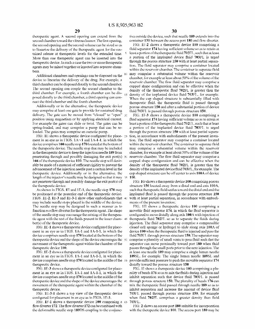
US 8,905,963 B2 29
therapeutic agent. A second opening can extend from the second chambertoward the vitreous humor. The first opening, the second opening and the second Volume can be sized so as to linearize the delivery of the therapeutic agent for the sus tained release at therapeutic levels for the extended time. More than one therapeutic agent can be inserted into the therapeutic device. In such a case the two or more therapeutic agents may be mixed together or injected into separate cham bers.
Additional chambers and openings can be disposed on the device to linearize the delivery of the drug. For example, a third chamber can be disposed distally to the second chamber. The second opening can couple the second chamber to the third chamber. For example, a fourth chamber can be dis posed distally to the third chamber, a third opening can con nect the third chamber and the fourth chamber.
Additionally or in the alternative, the therapeutic device may comprise at least one gate to provide for Sustained drug delivery. The gate can be moved from “closed to “open’ position using magnetism or by applying electrical current. For example the gates can slide or twist. The gates can be spring-loaded, and may comprise a pump that can be re loaded. The gates may comprise an osmotic pump.
FIG. 1E shows a therapeutic device configured for place ment in an eye as in FIGS. 1A 1 and 1A-1-1, in which the device comprises 100 needle stop 170 located at the bottom of the therapeutic device. The needle stop that may be included in the therapeutic device to keep the injection needle 189 from penetrating through and possibly damaging the exit port(s) 166 of the therapeutic device 100. The needle stop will desir ably be made of a material of sufficient rigidity to prevent the advancement of the injection needle past a certain level in the therapeutic device. Additionally or in the alternative, the length of the injector's needle may be designed so that it may not penetrate through and possibly damage the exit port(s) of the therapeutic device. As shown in FIGS. 1E and 1 E-1, the needle stop 170 may
be positioned at the posterior end of the therapeutic device. FIGS. 1E-2, 1 E-3 and 1 E-3-1 show other embodiments that may include needle stops placed in the middle of the device. The needle stop may be designed in Such a manner as to function as a flow diverter for the therapeutic agent. The shape of the needle stop may encourage the mixing of the therapeu tic agent with the rest of the fluids present in the inner cham ber(s) of the therapeutic device.
FIG.1E-1 shows a therapeutic device configured for place ment in an eye as in FIGS. 1A-1 and 1A-1-1, in which the device comprises needle stop 170 located at the bottom of the therapeutic device and the shape of the device encourages the movement of the therapeutic agent within the chamber of the therapeutic device 100.
FIG.1E-2 shows a therapeutic device configured for place ment in an eye as in FIGS. 1A-1 and 1A-1-1, in which the device comprises needle stop 170 located in the middle of the therapeutic device.
FIG.1E-3 shows a therapeutic device configured for place ment in an eye as in FIGS. 1A-1 and 1A-1-1, in which the device comprises needle stop 170 located in the middle of the therapeutic device and the shape of the device encourages the movement of the therapeutic agent within the chamber of the therapeutic device.
FIG. 1 E-3-1 shows a top view of the therapeutic device configured for placement in an eye as in FIGS. 1 E-3.
FIG. 1F-1 shows a therapeutic device 100 comprising a flow diverter 172. The flow diverter 172 can be combined with the deformable needle stop 189DS coupling to the conjunc
10
15
25
30
35
40
45
50
55
60
65
30 tiva outside the device, such that needle 189 extends into the container 130 between the access port 180 and flow diverter.
FIG. 1 F-2 shows a therapeutic device 100 comprising a fluid separator 174 having sufficient volume so as to retain at least a portion of the therapeutic fluid 702FL, such that at least a portion of the implanted device fluid 703FL is urged through the porous structure 150 with at least partial separa tion. The fluid separator may comprise a container located within the reservoir chamber. The container to separate fluid may comprise a Substantial Volume within the reservoir chamber, for example at least about 50% of the volume of the reservoir chamber. The flow fluid separator may comprise a cupped shape configuration and can be effective when the density of the therapeutic fluid 702FL is greater than the density of the implanted device fluid 703FL, for example. When the cup shaped structure is substantially filled with therapeutic fluid, the therapeutic fluid is passed through porous structure 150 and after a substantial portion of device fluid 703FL is passed through porous structure 150.
FIG. 1 F-3 shows a therapeutic device 100 comprising a fluid separator 174 having sufficient volume so as to retain at least a portion of the therapeutic fluid 702FL, such that at least a portion of the implanted device fluid 703FL is urged through the porous structure 150 with at least partial separa tion, in accordance with embodiments of the present inven tion. The fluid separator may comprise a container located within the reservoir chamber. The container to separate fluid may comprise a Substantial Volume within the reservoir chamber, for example at least about 50% of the volume of the reservoir chamber. The flow fluid separator may comprise a cupped shape configuration and can be effective when the density of the therapeutic fluid 702FL is greater than the density of the implanted device fluid 703FL, for example. The cup shaped structure can be off center to axis 100A of device 1OO. FIG.1G shows atherapeutic device 100 comprising porous
structure 150 located away from a distal end and axis 100A, such that therapeutic fluid settles toward the distal end and the implanted fluid is passed through the porous structure 150 with at least partial separation, in accordance with embodi ments of the present invention;
FIG. 1H shows a therapeutic device 100 comprising a movable fluid separator 174, in which the fluid separator is configured to move distally along axis 100A with injection of therapeutic fluid 702FL so as to separate the fluids during injection. The fluid separator may comprise a compressible closed cell sponge or hydrogel to slide along axis 100A of device 100 when the therapeutic fluid is injected and pass the fluid 703FL through porous structure 150. The separator may comprise a plurality of Small vents to pass fluid Such that the separator can move proximally toward port 180 when fluid passes through the Small ports prior to the next injection. The at least one needle 189 may comprise a single lumen needle 189SL, for example. The single lumen needle 189SL and provide sufficient pressure to push the movable separator 174 distally toward the porous structure 150
FIG. 1I shows a therapeutic device 100 comprising a plu rality of beads 176 so as to mix the fluids during injection and inhibit separation such that device fluid 703FL is passed through porous structure 150. The plurality of beads 176 can mix the therapeutic fluid passed through needle 189 so as to inhibit separation and increase the amount of device fluid 703FL passed through porous structure 150, for example when fluid 702FL comprises a greater density than fluid 703FL.
FIG. 2 shows an access port 180 suitable for incorporation with the therapeutic device 100. The access port 180 may be

US 8,905,963 B2 31
combined with the therapeutic devices described herein, for example with reference to FIGS. 1A-1 to 1D. The access port may be disposed on a proximal end of the device. The access port 180 may comprise an opening formed in the retention structure 120 with a penetrable barrier 184 comprising a septum 186 disposed thereon. The access port may 180 be configured for placement under the conjunctiva 16 of the patient and above the sclera 24.
FIG. 3A shows a collar 128 suitable for incorporation with the therapeutic device 100. The retention structure 120 con figured to couple to the sclera 24 may comprise the collar 128. The collar may comprise an expandable collar.
FIG. 3B shows biocompatible material impregnated with an anti-bacterial agent 310 on the therapeutic device 100 to inhibit bacterial growth along the device from the sclera to the vitreous humor. The biocompatible material may comprise collagen, for example a collagen sponge 312, and the anti bacterial agent may comprise silver impregnated in the col lagen. The biocompatible material impregnated with the bac tericide agent may extend around at least a portion of the outer Surface of the device. The anti-bacterial agent may comprise a portion of the retention structure 120, such that the anti bacterial agent is disposed at least partially within the Sclera when the device is inserted into the eye.
FIG. 4A shows released antibodies comprising antibody fragments 410 and a Substrate 420 comprising binding agent 190, and FIG. 413 shows an antibody fragments 410 revers ibly bound to a substrate 420 with binding agent 190, in accordance with embodiments of the present invention. The anti-body fragments can be reversibly bound to the substrate comprising the binding agent, such that the bound antibody fragments are in equilibrium with the unbound antibody frag ments. One of ordinary skill in the art will recognize many Substrates comprising binding agent to reversibly bind at least a portion of an antibody based on the teachings described herein. Examples of binding media may include particulates used in chromatography, such as: Macro-Prep t-Butyl HIC Support, Macro-Prep DEAE Support, CHT Ceramic, Hydroxyapatite Type I, Macro-Prep CM Support, Macro Prep Methyl HIC Support, Macro-Prep Ceramic Hydroxapa tite Type II, UNOsphere S Cation Exchange Support, UNO sphere Q Strong Anion Exchange Support, Macro-Prep High-S Support, and Macro-Prep High-Q Support. Additional media to test for binding include ion exchange and bioaffinity chromatography media based on a hydrophilic polymeric support (GE Healthcare) that bind proteins with high capacity, and a hydrophilic packing material from Har vard Apparatus made from poly(vinyl alcohol) that binds more protein than silica. Other candidates would be known to those knowledgeable in the art.
FIG. 5A shows therapeutic device 100 coupled to injector 187 to insert therapeutic agent 110 into container 130 of the device. The injector 187 may comprise needle 189 coupled to a syringe 188.
FIG. 5A-1 shows a therapeutic device 100 coupled to an injector 187 to inject and remove material from the device. The injector may comprise needle 189 having a first lumen 189A and a second lumen 189B configured to insert into a container of the device. The injector may simultaneously inject 510 therapeutic agent into and withdraw 520 liquid from the device. The injector may comprise a first one way valve and a second one way valve coupled to the first lumen and the second lumen, respectively.
FIG. 5B shows a therapeutic device comprising a microloop channel 530. The microloop channel may extend to a first port 530A and a second port 530B, such the thera peutic agent can be injected into the first port, for example
10
15
25
30
35
40
45
50
55
60
65
32 with a binding agent, and flowable material, for example liquid comprising binding agent, can be drawn from the microloop channel 530.
FIG.5C-1 shows therapeutic device 100 comprising a tor tuous channel 540. The tortuous channel may comprise extend from a first port 540A to a second port 540B, such that the therapeutic agent can be injected into the first port and flowable material, for example liquid comprising the binding agent, can be drawn from the second channel.
FIG. 5C-2 shows a therapeutic device comprising a tortu ous coiled channel 550. The coiled channel 550 can extend to an exit port 552. A needle 189 can be inserted into the port 180 to inject therapeutic agent into device 100.
FIG. 5D shows an expandable and contractible structure 562 to retain the therapeutic agent and an outer rigid casing 560 to couple to the sclera. The expandable structure 562 may comprise a membrane. Such as at least one of a bag, a balloon, a flexible reservoir, a diaphragm, or a bag. The outer rigid casing may extend Substantially around the structure 562 and may comprise an opening to release liquid into the vitreous humor when the structure is expanded and to draw vitreous humor inside a chamber of the casing when material is drawn from the structure and the structure contacts. FIG.5E shows a membrane 550 disposed over an exit port
552 of therapeutic device 100. FIG.5F shows therapeutic device 100 comprising a tubular
membrane 572 clamped onto the therapeutic device over side ports 570 of device 100. When the protective membranes have pores of 0.2 urn
diameter, they are 20 or more times larger than the proteins of interest, which may comprise a model for delivery of the therapeutic agent. For example, molecular weights and diam eters of models of proteins of therapeutic interest are
(a) IgG 150 kDa 10.5 nm. (b) BSA 69 kDa 7.2 mm (c) Fab fragment of IgG 49 kDa hydrodynamic diameter not
reported
Therefore, Solutions of therapeutic compounds in the size range of IgG and BSA should flow relatively easily through 0.2 um pore size protective membranes used to stop passage of bacterial and other cells.
Binding Materials/Agents may comprise at least one of a chemical binding agent/material, a structural binding agent or material, or an electrostatic binding agent or material. The types of binding agent may comprise a classification com posed of non-biodegradable material, for example at glass beads, glass wool or a glass rod. A Surface can be derivatized with at least one functional group so as to impart the binding agent or material with the potential for at least one of ionic, hydrophobic, or bioaffinity binding to at least one therapeutic compound. The binding agent may comprise a biodegradable material.
For example, the biodegradation, binding, or a combination of the previous processes may control the diffusion rate. The binding agent may comprise ion exchange, and the ion
exchange may comprise at least one of a functional group, a pH sensitive binding or a positive or negative charge. For example, ion exchange with at least one of diethylaminoethyl or carboxymethyl functional groups. The binding agent may comprise a pH sensitive binding
agent. For example the binding agent can be configured to elute therapeutic agentata pH of 7, and to bind the therapeutic agent at a pH from about 4 to about 6.5. A cation exchange binding agent can be configured, for example, such that at a
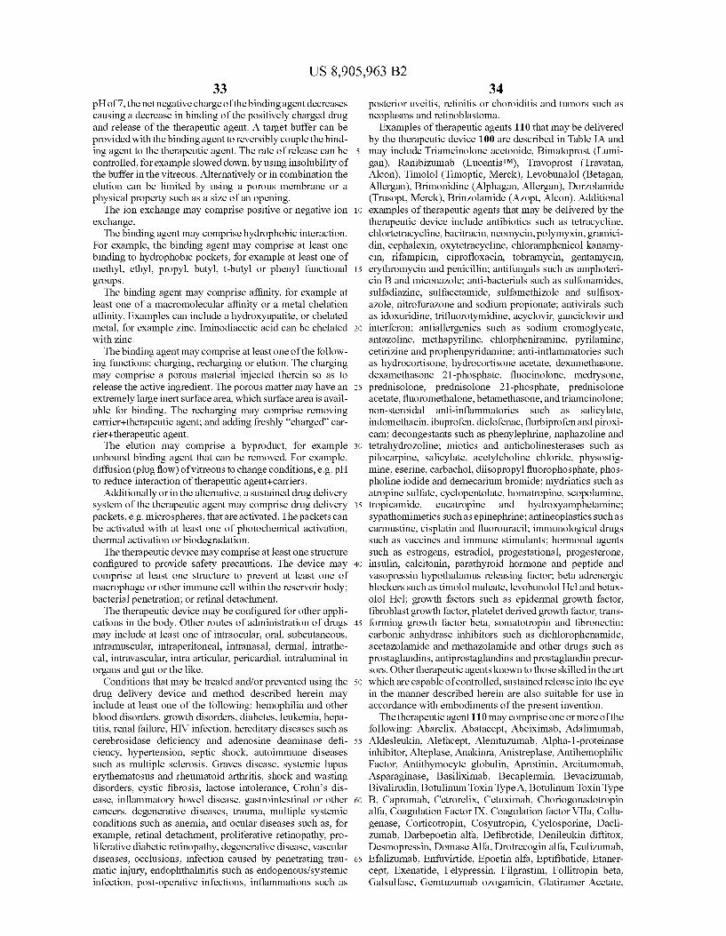
US 8,905,963 B2 33
pH of7, the net negative charge of the binding agent decreases causing a decrease in binding of the positively charged drug and release of the therapeutic agent. A target buffer can be provided with the binding agent to reversibly couple the bind ing agent to the therapeutic agent. The rate of release can be controlled, for example slowed down, by using insolubility of the buffer in the vitreous. Alternatively or in combination the elution can be limited by using a porous membrane or a physical property Such as a size of an opening. The ion exchange may comprise positive or negative ion
exchange. The binding agent may comprise hydrophobic interaction.
For example, the binding agent may comprise at least one binding to hydrophobic pockets, for example at least one of methyl, ethyl, propyl, butyl, t-butyl or phenyl functional groups. The binding agent may comprise affinity, for example at
least one of a macromolecular affinity or a metal chelation affinity. Examples can include a hydroxyapatite, or chelated metal, for example zinc. Iminodiacetic acid can be chelated with zinc.
The binding agent may comprise at least one of the follow ing functions: charging, recharging or elution. The charging may comprise a porous material injected therein so as to release the active ingredient. The porous matter may have an extremely large inert Surface area, which Surface area is avail able for binding. The recharging may comprise removing carrier--therapeutic agent; and adding freshly “charged car rier+therapeutic agent. The elution may comprise a byproduct, for example
unbound binding agent that can be removed. For example, diffusion (plug flow) of vitreous to change conditions, e.g. pH to reduce interaction of therapeutic agent+carriers.
Additionally or in the alternative, a sustained drug delivery system of the therapeutic agent may comprise drug delivery packets, e.g. microspheres, that are activated. The packets can be activated with at least one of photochemical activation, thermal activation or biodegradation.
The therapeutic device may comprise at least one structure configured to provide safety precautions. The device may comprise at least one structure to prevent at least one of macrophage or other immune cell within the reservoir body; bacterial penetration; or retinal detachment.
The therapeutic device may be configured for other appli cations in the body. Other routes of administration of drugs may include at least one of intraocular, oral, Subcutaneous, intramuscular, intraperitoneal, intranasal, dermal, intrathe cal, intravascular, intra articular, pericardial, intraluminal in organs and gut or the like.
Conditions that may be treated and/or prevented using the drug delivery device and method described herein may include at least one of the following: hemophilia and other blood disorders, growth disorders, diabetes, leukemia, hepa titis, renal failure, HIV infection, hereditary diseases such as cerebrosidase deficiency and adenosine deaminase defi ciency, hypertension, septic shock, autoimmune diseases Such as multiple Sclerosis, Graves disease, systemic lupus erythematosus and rheumatoid arthritis, shock and wasting disorders, cystic fibrosis, lactose intolerance, Crohn's dis ease, inflammatory bowel disease, gastrointestinal or other cancers, degenerative diseases, trauma, multiple systemic conditions such as anemia, and ocular diseases Such as, for example, retinal detachment, proliferative retinopathy, pro liferative diabetic retinopathy, degenerative disease, vascular diseases, occlusions, infection caused by penetrating trau matic injury, endophthalmitis such as endogenous/systemic infection, post-operative infections, inflammations such as
10
15
25
30
35
40
45
50
55
60
65
34 posterior uveitis, retinitis or choroiditis and tumors such as neoplasms and retinoblastoma.
Examples of therapeutic agents 110 that may be delivered by the therapeutic device 100 are described in Table IA and may include Triamcinolone acetonide, Bimatoprost (Lumi gan), Ranibizumab (LucentisTM). Travoprost (Travatan, Alcon), Timolol (Timoptic, Merck), Levobunalol (Betagan, Allergan), Brimonidine (Alphagan, Allergan), Dorzolamide (Trusopt, Merck), Brinzolamide (Azopt, Alcon). Additional examples of therapeutic agents that may be delivered by the therapeutic device include antibiotics such as tetracycline, chlortetracycline, bacitracin, neomycin, polymyxin, gramici din, cephalexin, oxytetracycline, chloramphenicol kanamy cin, rifampicin, ciprofloxacin, tobramycin, gentamycin, erythromycin and penicillin; antifungals such as amphoteri cin B and miconazole; anti-bacterials such as Sulfonamides, Sulfadiazine, Sulfacetamide, Sulfamethizole and Sulfisox azole, nitrofuraZone and sodium propionate; antivirals such as idoxuridine, trifluorotymidine, acyclovir, ganciclovir and interferon; antiallergenics such as sodium cromoglycate, antazoline, methapyriline, chlorpheniramine, pyrilamine, cetirizine and prophenpyridamine; anti-inflammatories Such as hydrocortisone, hydrocortisone acetate, dexamethasone, dexamethasone 21-phosphate, fluocinolone, medrysone, prednisolone, prednisolone 21-phosphate, prednisolone acetate, fluoromethalone, betamethasone, and triamcinolone; non-steroidal anti-inflammatories such as Salicylate, indomethacin, ibuprofen, diclofenac, flurbiprofen and piroxi cam; decongestants such as phenylephrine, naphazoline and tetrahydrozoline; miotics and anticholinesterases such as pilocarpine, Salicylate, acetylcholine chloride, physostig mine, eserine, carbachol, diisopropyl fluorophosphate, phos pholine iodide and demecarium bromide; mydriatics such as atropine Sulfate, cyclopentolate, homatropine, Scopolamine, tropicamide, eucatropine and hydroxyamphetamine; Sypathomimetics Such as epinephrine; antineoplastics such as carmustine, cisplatin and fluorouracil; immunological drugs Such as vaccines and immune stimulants; hormonal agents Such as estrogens, estradiol, progestational, progesterone, insulin, calcitonin, parathyroid hormone and peptide and vasopressin hypothalamus releasing factor, beta adrenergic blockers such as timolol maleate, levobunolol Holand betax olol Hel; growth factors such as epidermal growth factor, fibroblast growth factor, platelet derived growth factor, trans forming growth factor beta, Somatotropin and fibronectin; carbonic anhydrase inhibitors such as dichlorophenamide, acetazolamide and methazolamide and other drugs such as prostaglandins, antiprostaglandins and prostaglandin precur sors. Other therapeutic agents known to those skilled in the art which are capable of controlled, sustained release into the eye in the manner described herein are also suitable for use in accordance with embodiments of the present invention. The therapeutic agent 110 may comprise one or more of the
following: Abarelix, Abatacept, Abciximab, Adalimumab, Aldesleukin, Alefacept, Alemtuzumab, Alpha-1-proteinase inhibitor, Alteplase, Anakinra, Anistreplase, Antihemophilic Factor, Antithymocyte globulin, Aprotinin, Arcitumomab, Asparaginase, Basiliximab, Becaplermin, Bevacizumab, Bivalirudin, Botulinum Toxin Type A, Botulinum Toxin Type B, Capromab, Cetrorelix, Cetuximab, Choriogonadotropin alfa, Coagulation Factor IX, Coagulation factor VIIa, Colla genase, Corticotropin, Cosyntropin, Cyclosporine, Dacli Zumab, Darbepoetin alfa, Defibrotide, Denileukin diftitox, Desmopressin, Domase Alfa, Drotrecogin alfa, Eculizumab, Efalizumab, Enfluvirtide, Epoetin alfa, Eptifibatide, Etaner cept, Exenatide, Felypressin, Filgrastim, Follitropin beta, Galsulfase, Gemtuzumab ozogamicin, Glatiramer Acetate,

US 8,905,963 B2 35
Glucagon recombinant, Goserelin, Human Serum Albumin, Hyaluronidase, Ibritumomab, Idursulfase, Immune globulin, Infliximab, Insulin Glargine recombinant, Insulin Lyspro recombinant, Insulin recombinant, Insulin, porcine, Inter feron Alfa-2a, Recombinant, Interferon Alfa-2b, Recombi nant, Interferon alfacon-1, Interferonalfa-n1, Interferon alfa n3, Interferon beta-1b, Interferon gamma-1b, Lepirudin, Leuprolide, Lutropin alfa, Mecasermin, Menotropins, Muromonab, Natalizumab, Nesiritide, Octreotide, Omali Zumab, Oprelvekin, OspAlipoprotein, Oxytocin, Palifermin, Palivizumab, Panitumumab, Pegademase bovine, Pegap tanib, Pegaspargase, Pegfilgrastim, Peginterferon alfa-2a, Peginterferon alfa-2b, Pegvisomant, Pramlintide, Ranibi Zumab, Rasburicase, Reteplase, Rituximab, Salmon Calcito nin, SargramoStim, Secretin, Sermorelin, Serum albumin iodonated. Somatropin recombinant, Streptokinase, Tenect eplase, Teriparatide, Thyrotropin Alfa, Tositumomab, Trastu Zumab, Urofolitropin, Urokinase, or Vasopressin. The molecular weights of the molecules and indications of these therapeutic agents are set for below in Table 1A, below.
The therapeutic agent 110 may comprise one or more of compounds that act by binding members of the immunophilin family of cellular proteins. Such compounds are known as “immunophilin binding compounds. Immunophilin binding compounds include but are not limited to the “limus' family of compounds. Examples of limus compounds that may be used include but are not limited to cyclophilins and FK506 binding proteins (FKBPs), including sirolimus (rapamycin) and its water soluble analog SDZ-RAD, tacrolimus, everoli mus, pimecrolimus, CCI-779 (Wyeth), AP23841 (Ariad), and ABT-578 (Abbott Laboratories). The limus family of compounds may be used in the com
positions, devices and methods for the treatment, prevention, inhibition, delaying the onset of, or causing the regression of angiogenesis-mediated diseases and conditions of the eye, including choroidal neovascularization. The limns family of compounds may be used to prevent, treat, inhibit, delay the onset of, or cause regression of AMD, including wet AMD. Rapamycin may be used to prevent, treat, inhibit, delay the onset of, or cause regression of angiogenesis-mediated dis eases and conditions of the eye, including choroidal neovas cularization. Rapamycin may be used to prevent, treat, inhibit, delay the onset of, or cause regression of AMD, including wet AMD. The therapeutic agent 110 may comprise one or more of
pyrrolidine, dithiocarbamate (NF kappa.B inhibitor): squalamine: TPN 470 analogue and fumagillin; PKC (protein kinase C) inhibitors; Tie-1 and Tie-2 kinase inhibitors; inhibi tors of VEGF receptor kinase; proteosome inhibitors such as VelcadeTM (bortezomib, for injection; ranibuZumab (Lucen tisTM) and other antibodies directed to the same target; pegap tanib (MacugenTM); vitronectin receptor antagonists, such as cyclic peptide antagonists of vitronectin receptor-type inte grins; alpha.-V/.beta.-3 integrin antagonists; alpha.-V/ .beta.-1 integrin antagonists; thiazolidinediones such as rosiglitaZone or troglitaZone; interferon, including gamma.- interferon or interferon targeted to CNV by use of dextranand metal coordination; pigment epithelium derived factor (PEDF); endostatin: angiostatin; tumistatin: can statin: anecortave acetate; acetonide; triamcinolone; tetrathiomo lybdate; RNA silencing or RNA interference (RNAi) of angiogenic factors, including ribozymes that target VEGF expression: AccutaneTM (13-cis retinoic acid); ACE inhibi tors, including but not limited to quinopril, captopril, and perindozril; inhibitors of mTOR (mammalian target of rapa mycin); 3-aminothalidomide; pentoxifylline, 2-methox yestradiol; colchicines; AMG-1470; cyclooxygenase inhibi
10
15
25
30
35
40
45
50
55
60
65
36 tors such as nepafenac, rofecoxib, diclofenac, rofecoxib, NS398, celecoxib, Vioxx, and (E)-2-alkyl-2(4-methanesulfo nylphenyl)-1-phenylethene; t-RNA synthase modulator; metalloprotease 13 inhibitor; acetylcholinesterase inhibitor; potassium channel blockers; endorepellin; purine analog of 6-thioguanine; cyclic peroxide ANO-2; (recombinant) argin ine deiminase; epigallocatechin-3-gallate; cerivastatin; ana logues of Suramin; VEGF trap molecules; apoptosis inhibit ing agents; VisudyneTM, SnBT2 and other photo sensitizers, which may be used with photodynamic therapy (PDT): inhibitors of hepatocyte growth factor (antibodies to the growth factor or its receptors, small molecular inhibitors of the c-met tyrosine kinase, truncated versions of HGF e.g. NK4). The therapeutic agent 110 may comprise a combination
with other therapeutic agents and therapies, including but not limited to agents and therapies useful for the treatment of angiogenesis or neovascularization, particularly CNV. Non limiting examples of Such additional agents and therapies include pyrrolidine, dithiocarbamate (NF kappa.B inhibitor); squalamine: TPN 470 analogue and fumagillin; PKC (protein kinase C) inhibitors: Tie-1 and Tie-2 kinase inhibitors; inhibi tors of VEGF receptor kinase; proteosome inhibitors such as VelcadeTM (bortezomib, for injection; ranibuzumab (Lucen tisTM) and other antibodies directed to the same target; pegap tanib (MacugenTM); vitronectin receptor antagonists, such as cyclic peptide antagonists of vitronectin receptor-type inte grins; alpha.-V/.beta-3 integrin antagonists; alpha.-V/ .beta.-1 integrin antagonists; thiazolidinediones such as rosiglitaZone or troglitaZone; interferon, including gamma.- interferon or interferon targeted to CNV by use of dextranand metal coordination; pigment epithelium derived factor (PEDF); endostatin: angiostatin; tumistatin: can statin: anecortave acetate; acetonide; triamcinolone; tetrathiomo lybdate: RNA silencing or RNA interference (RNAi) of angiogenic factors, including ribozymes that target VEGF expression: AccutaneTM (13-cis retinoic acid); ACE inhibi tors, including but not limited to quinopril, captopril, and perindozril; inhibitors of mTOR (mammalian target of rapa mycin); 3-aminothalidomide; pentoxifylline, 2-methox yestradiol; colchicines; AMG-1470; cyclooxygenase inhibi tors such as nepafenac, rofecoxib, diclofenac, rofecoxib, NS398, celecoxib, Vioxx, and (E)-2-alkyl-2(4-methanesulfo nylphenyl)-1-phenylethene; t-RNA synthase modulator; metalloprotease 13 inhibitor; acetylcholinesterase inhibitor; potassium channel blockers; endorepellin; purine analog of 6-thioguanine; cyclic peroxide ANO-2; (recombinant) argin ine deiminase; epigallocatechin-3-gallate; cerivastatin; ana logues of Suramin; VEGF trap molecules; inhibitors of hepa tocyte growth factor (antibodies to the growth factor or its receptors, Small molecular inhibitors of the c-met tyrosine kinase, truncated versions of HGF e.g. NK4); apoptosis inhibiting agents: VisudyneTM, SnET2 and other photo sensi tizers with photodynamic therapy (PDT); and laser photoco agulation. The therapeutic agents may be used in conjunction with a
pharmaceutically acceptable carrier Such as, for example, Solids Such as Starch, gelatin, Sugars, natural gums such as acacia, Sodium alginate and carboxymethyl cellulose; poly merS Such as silicone rubber, liquids such as sterile water, saline, dextrose, dextrose in water or saline; condensation products of castor oil and ethylene oxide, liquid glyceryl triester of a lower molecular weightfatty acid; lower alkanols: oils such as corn oil, peanut oil, Sesame oil, castor oil, and the like, with emulsifiers such as mono- or di-glyceride of a fatty acid, or a phosphatide Such as lecithin, polysorbate 80, and the like; glycols and polyalkylene glycols; aqueous media in
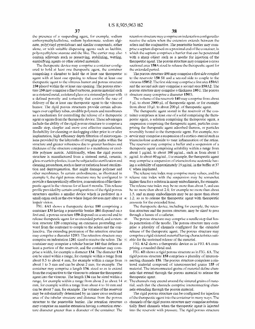
US 8,905,963 B2 37
the presence of a suspending agent, for example, sodium carboxymethylcellulose, sodium hyaluronate, sodium algi nate, poly(vinyl pyrrolidone) and similar compounds, either alone, or with Suitable dispensing agents such as lecithin, polyoxyethylene Stearate and the like. The carrier may also contain adjuvants such as preserving, stabilizing, wetting, emulsifying agents or other related materials. The therapeutic device may comprise a container config
ured to hold at least one therapeutic agent, the container comprising a chamber to hold the at least one therapeutic agent with at least one opening to release the at least one therapeutic agent to the vitreous humor and porous structure 150 placed within the at least one opening. The porous struc ture 150 may comprise a fixed tortuous, porous material such as a sintered metal, a sintered glass or a sintered polymer with a defined porosity and tortuosity that controls the rate of delivery of the at least one therapeutic agent to the vitreous humor. The rigid porous structures provide certain advan tages over capillary tubes, erodible polymers and membranes as a mechanism for controlling the release of a therapeutic agentoragents from the therapeutic device. These advantages include the ability of the rigid porous structure to comprise a needle stop, simpler and more cost effective manufacture, flushability for cleaning or declogging either prior to or after implantation, high efficiency depth filtration of microorgan isms provided by the labyrinths of irregular paths within the structure and greater robustness due to greater hardness and thickness of the structure compared to a membrane or erod ible polymer matrix. Additionally, when the rigid porous structure is manufactured from a sintered metal, ceramic, glass or certain plastics, it can be subjected to sterilization and cleaning procedures, such as heat or radiation based steriliza tion and depyrogenation, that might damage polymer and other membranes. In certain embodiments, as illustrated in example 9, the rigid porous structure may be configured to provide atherapeutically effective, concentration of the thera peutic agent in the vitreous for at least 6 months. This release profile provided by certain configurations of the rigid porous structures enables a smaller device which is preferred in a Small organ Such as the eye where larger devices may alter or impair vision.
FIG. 6A1 shows a therapeutic device 100 comprising a container 130 having a penetrable barrier 184 disposed on a first end, a porous structure 150 disposed on a second end to release therapeutic agent for an extended period, and a reten tion structure 120 comprising an extension protruding out ward from the container to couple to the Sclera and the con junctiva. The extending protrusion of the retention structure may comprise a diameter 120D. The retention structure may comprise an indentation 1201 sized to receive the sclera. The container may comprise a tubular barrier 160 that defines at least a portion of the reservoir, and the container may com prise a width, for example a diameter 134. The diameter 134 can be sized within a range, for example within a range from about 0.5 to about 4 mm, for example within a range from about 1 to 3 mm and can be about 2 mm, for example. The container may comprise a length 136, sized so as to extend from the conjunctive to the vitreous to release the therapeutic agent into the vitreous. The length 136 can be sized within a range, for example within a range from about 2 to about 14 mm, for example within a range from about 4 to 10 mm and can be about 7 mm, for example. The volume of the reservoir may be substantially determined by an inner cross sectional area of the tubular structure and distance from the porous structure to the penetrable barrier. The retention structure may comprise an annular extension having a retention struc ture diameter greater than a diameter of the container. The
10
15
25
30
35
40
45
50
55
60
65
38 retention structure may comprise an indentation configured to receive the sclera when the extension extends between the Sclera and the conjunctive. The penetrable barrier may com prise a septum disposed on a proximal end of the container, in which the septum comprises a barrier that can be penetrated with a sharp object such as a needle for injection of the therapeutic agent. The porous structure may comprise a cross sectional area 150A sized to release the therapeutic agent for the extended period. The porous structure 150 may comprise a first side coupled
to the reservoir 150 S1 and a second side to couple to the vitreous 150S2. The first side may comprise a first area 150A1 and the second side may comprise a second area 150A2. The porous structure may comprise a thickness 105T. The porous structure many comprise a diameter 150D. The volume of the reservoir 140 may comprise from about
5ul to about 2000 uL of therapeutic agent, or for example from about 10 uL to about 200 uL of therapeutic agent. The therapeutic agent stored in the reservoir of the con
tainer comprises at least one of a solid comprising the thera peutic agent, a solution comprising the therapeutic agent, a Suspension comprising the therapeutic agent, particles com prising the therapeutic agent adsorbed thereon, or particles reversibly bound to the therapeutic agent. For example, res ervoir may comprise a suspension of a cortico-steroid Such as triamcinolone acetonide to treat inflammation of the retina. The reservoir may comprise a buffer and a Suspension of a therapeutic agent comprising Solubility within a range from about 1 ug/mL to about 100 ug/mL, such as from about 1 ug/mL to about 40 ug/mL. For example, the therapeutic agent may comprise a suspension of triamcinolone acetonide hav ing a solubility of approximately 191g/mL in the buffer at 37 C when implanted. The release rate index may comprise many values, and the
release rate index with the Suspension may be somewhat higher than for a solution in many embodiments, for example. The release rate index may be no more than about 5, and can be no more than about 2.0, for example no more than about 1.5, and in many embodiments may be no more than about 1.2, so as to release the therapeutic agent with therapeutic amounts for the extended time. The therapeutic device, including for example, the reten
tion structure and the porous structure, may be sized to pass through a lumen of a catheter. The porous structure may comprise a needle stop that lim
its penetration of the needle. The porous structure may com prise a plurality of channels configured for the extended release of the therapeutic agent. The porous structure may comprise a rigid sintered material having characteristics Suit able for the sustained release of the material.
FIG. 6A2 shows a therapeutic device as in FIG. 6A com prising a rounded distal end.
FIG. 6B shows a rigid porous structure as in FIG. 6A. The rigid porous structure 158 comprises a plurality of intercon necting channels 156. The porous structure comprises a sin tered material composed of interconnected grains 155 of material. The interconnected grains of material define chan nels that extend through the porous material to release the therapeutic agent. The channels may extend around the sintered grains of mate rial. Such that the channels comprise interconnecting chan nels extending through the porous material. The rigid porous structure can be configured for injection
of the therapeutic agent into the container in many ways. The channels of the rigid porous structure may comprise Substan tially fixed channels when the therapeutic agent is injected into the reservoir with pressure. The rigid porous structure

US 8,905,963 B2 39
comprises a hardness parameter within a range from about 160 Vickers to about 500 Vickers. In some embodiments the rigid porous structure is formed from sintered stainless Steel and comprises a hardness parameter within a range from about 200 Vickers to about 240 Vickers. In some embodi ments it is preferred to inhibit ejection of the therapeutic agent through the porous structure during filling or refilling the reservoir of the therapeutic device with a fluid. In these embodiments the channels of the rigid porous structure com prise a resistance to flow of an injected Solution or Suspension through a thirty gauge needle Such that ejection of said solu tion or Suspension through the rigid porous structure is Sub stantially inhibited when said solution or Suspension is injected into the reservoir of the therapeutic device. Addition ally, these embodiments may optionally comprise an evacu ation vent or an evacuation reservoir under vacuum or both to facilitate filling or refilling of the reservoir. The reservoir and the porous structure can be configured to
release therapeutic amounts of the therapeutic agent in many ways. The reservoir and the porous structure can be config ured to release therapeutic amounts of the therapeutic agent corresponding to a concentration of at least about 0.1 g per ml of vitreous humor for an extended period of at least about three months. The reservoir and the porous structure can be configured to release therapeutic amounts of the therapeutic agent corresponding to a concentration of at least about 0.1 ug per ml of vitreous humor and no more than about 10g perml for an extended period of at least about three months. The therapeutic agent may comprise at least a fragment of an antibody and a molecular weight of at least about 10k Dal tons. For example, the therapeutic agent may comprise one or more of ranibizumab or bevacizumab. Alternatively or in combination, the therapeutic agent may comprise a small molecule drug suitable for sustained release. The reservoir and the porous structure may be configured to release thera peutic amounts of the therapeutic agent corresponding to a concentration of at least about 0.1 ug per ml of vitreous humor and no more than about 10 ug per ml for an extended period of at least about 3 months or at least about 6 months. The reservoir and the porous structure can be configured to release therapeutic amounts of the therapeutic agent corresponding to a concentration of at least about 0.1 ug per ml of vitreous humor and no more than about 10 ug per ml for an extended period of at least about twelve months or at least about two years or at least about three years. The reservoir and the porous structure may also be configured to release therapeutic amounts of the therapeutic agent corresponding to a concen tration of at least about 0.01 ug per ml of vitreous humor and no more than about 300 ug per ml for an extended period of at least about 3 months or 6 months or 12 months or 24 months. The channels of the rigid porous structure comprise a
hydrogel configured to limit a size of molecules passed through the channels of the rigid porous structure. For example, the hydrogel can beformed within the channels and may comprise an acrylamide gel. The hydrogel comprises a water content of at least about 70%. For example, the hydro gel may comprise a water content of no more than about 90% to limit molecular weight of the therapeutic agent to about 30 kDaltons. The hydrogel comprises a water content of no more than about 95% to limit molecular weight of the therapeutic agent to about 100 kDaltons. The hydrogel may comprise a water content within a range from about 90% to about 95% Such that the channels of the porous material are configured to pass LucentisTM and substantially not pass AvastinTM. The rigid porous structure may comprise a composite
porous material that can readily be formed in or into a wide range of different shapes and configurations. For example, the
10
15
25
30
35
40
45
50
55
60
65
40 porous material can be a composite of a metal, aerogel or ceramic foam (i.e., a reticulated inter-cellular structure in which the interior cells are interconnected to provide a mul tiplicity of pores passing through the Volume of the structure, the walls of the cells themselves being substantially continu ous and non-porous, and the Volume of the cells relative to that of the material forming the cell walls being such that the overall density of the intercellular structure is less than about 30 percent theoretical density) the through pores of which are impregnated with a sintered powder or aerogel. The thick ness, density, porosity and porous characteristics of the final composite porous material can be varied to conform with the desired release of the therapeutic agent.
Embodiments comprise a method of making an integral (i.e., single-component) porous structure. The method may comprise introducing particles into a mold having a desired shape for the porous structure. The shape includes a proximal end defining a plurality of proximal porous channel openings to couple to the reservoir, a distal end defining a plurality of outlet channel openings to couple to the vitreous humor of the eye, a plurality of blind inlet cavities extending into the filter from the proximal openings, and a plurality of blind outlet cavities extending into the porous structure from the outlet channel openings. The method further includes applying pressure to the mold, thereby causing the particles to cohere and form a single component, and sintering the component to form the porous structure. The particles can be pressed and cohere to form the component without the use of a polymeric binder, and the porous structure can be formed substantially without machining. The mold can be oriented vertically with the open otherend
disposed upwardly, and metal powder having aparticle size of less than 20 micrometers can be introduced into the cavity through the open end of the mold while vibrating the mold to achieve Substantially uniform packing of the metal powder in the cavity. A cap can be placed on the open other end of the mold, and pressure is applied to the mold and thereby to the metal powder in the cavity to cause the metal powder to cohere and form a cup-shaped powdered metal structure hav ing a shape corresponding to the mold. The shaped powdered metal structure can be removed from the mold, and sintered to obtain a porous sintered metal porous structure. The metal porous structure can be incorporated into the
device by a press fit into an impermeable structure with an opening configured to provide a tight fit with the porous structure. Other means, such as welding, known to those skilled in the art can be used to incorporate the porous struc ture into the device. Alternatively, or in combination, the powdered metal structure can be formed in a mold where a portion of the mold remains with the shaped powdered metal structure and becomes part of the device. This may be advan tageous in achieving a good seal between the porous structure and the device. The release rate of therapeutic agent through a porous
body, such as a sintered porous metal structure or a porous glass structure, may be described by diffusion of the of the therapeutic agent within the porous structure with the channel parameter, and with an effective diffusion coefficient equal to the diffusion coefficient of the therapeutic agent in the liquid that fills the reservoir multiplied by the Porosity and a Chan nel Parameter of the porous body:
Release Rate=(DP/F)A (c-c)/L, where: c-Concentration in reservoir c-Concentration outside of the reservoir or in the vitreous

US 8,905,963 B2 41
D=Diffusion coefficient of the therapeutic agent in the reser voir solution
P=Porosity of porous structure F-Channel parameter that may correspond to a tortuosity parameter of channels of porous structure A=Area of porous structure L=Thickness (length) of porous structure
Cumulative Release=1-cR/cRO=1-exp(-D PA/FL VR)t),
where t-time, Vr reservoir volume The release rate index can (hereinafter RRI) be used to
determine release of the therapeutic agent. The RRI may be defined as (PA/FL), and the RRI values herein will have units of mm unless otherwise indicated. Many of the porous struc tures used in the therapeutic delivery devices described here have an RRI of no more than about 5.0, often no more than about 2.0, and can be no more than about 1.2 mm. The channel parameter can correspond to an elongation of
the path of the therapeutic agent released through the porous structure. The porous structure may comprise many intercon necting channels, and the channel parameter can correspond to an effective length that the therapeutic agent travels along the interconnecting channels of the porous structure from the reservoir side to the vitreous side when released. The channel parameter multiplied by the thickness (length) of the porous structure can determine the effective length that the therapeu tic agent travels along the interconnecting channels from the reservoir side to the vitreous side. For example, the channel parameter (F) of about 1.5 corresponds to interconnecting channels that provide an effective increase in length traveled by the therapeutic agent of about 50%, and for a 1 mm thick porous structure the effective length that the therapeutic agent travels along the interconnecting channels from the reservoir side to the vitreous side corresponds to about 1.5 mm. The channel parameter (F) of at least about 2 corresponds to interconnecting channels that provide an effective increase in length traveled by the therapeutic agent of about 100%, and for a 1 mm thick porous structure the effective length that the therapeutic agent travels along the interconnecting channels from the reservoir side to the vitreous side corresponds to at least about 2.0 mm. As the porous structure comprises many interconnecting channels that provide many alternative paths for release of the therapeutic agent, blockage of Some of the channels provides no substantial change in the effective path length through the porous structure as the alternative inter connecting channels are available. Such that the rate of diffu sion through the porous structure and the release of the thera peutic agent are substantially maintained when some of the channels are blocked.
If the reservoir Solution is aqueous or has a viscosity simi lar to water, the value for the diffusion coefficient of the therapeutic agent (TA) in water at the temperature of interest may be used. The following equation can be used to estimate the diffusion coefficient at 37° C. from the measured value of
Disco -6.1e-7 cm2/s for bovine serum albumin in water at 20° C. (Molokhia et al. Exp Eye Res 2008):
D1437c-Des-42oc(n20cm37c)(MWasa MW)' where
MW refers to the molecular weight of either BSA or the test compound and m is the Viscosity of water. The following lists diffusion coefficients of proteins of interest.
5
10
15
25
30
35
40
45
50
55
60
65
42
Diff Compound MW Temp C. Coeff (cm 2s)
BSA 69,000 2O 6.1E-07 BSA 69,000 37 9.1E-07 Ranibizumab 48,000 2O 6.9E-07 Ranibizumab 48,000 37 1.OE-06 Bevacizumab 149,000 2O 4.7E-07 Bevacizumab 149,000 37 7.1E-07
Small molecules have a diffusion coefficient similar to fluo rescein (MW=330, D=4.8 to 6 e-6cm/s from Stay, MS et al. Pharm Res 2003, 2001), pp. 96-102). For example, the small molecule may comprise a glucocorticoid such as triamcino lone acetonide having a molecular weight of about 435. The porous structure comprises a porosity, a thickness, a
channel parameter and a Surface area configured to release therapeutic amounts for the extended period. The porous material may comprise a porosity corresponding to the frac tion of void space of the channels extending within the mate rial. The porosity comprises a value within a range from about 3% to about 70%. In other embodiments, the porosity com prises a value with a range from about 5% to about 10% or from about 10% to about 25%, or for example from about 15% to about 20%. Porosity can be determined from the weight and macroscopic Volume or can be measured via nitrogen gas adsorption The porous structure may comprise a plurality of porous
structures, and the area used in the above equation may com prise the combined area of the plurality of porous structures. The channel parameter may comprise a fit parameter cor
responding to the tortuosity of the channels. For a known porosity, Surface area and thickness of the Surface parameter, the curve fit parameter F, which may correspond to tortuosity of the channels can be determined based on experimental measurements. The parameter PA/FL can be used to deter mine the desired sustained release profile, and the values of P. A, F and L determined. The rate of release of the therapeutic agent corresponds to a ratio of the porosity to the channel parameter, and the ratio of the porosity to the channel param eter can be less than about 0.5 such that the porous structure releases the therapeutic agent for the extended period. For example, the ratio of the porosity to the channel parameter is less than about 0.1 or for example less than about 0.2 such that the porous structure releases the therapeutic agent for the extended period. The channel parameter may comprise a value of at least about 1, such as at least about 1.2. For example, the value of the channel parameter may comprise at least about 1.5, for example at least about 2, and may com prise at least about 5. The channel parameter can be within a range from about 1.1 to about 10, for example within a range from about 1.2 to about 5. A person of ordinary skill in the art can conduct experiments based on the teachings described herein to determine empirically the channel parameter to release the therapeutic agent for an intended release rate profile. The area in the model originates from the description of
mass transported in units of flux; i.e., rate of mass transfer per unit area. For simple geometries, such as a porous disc mounted in an impermeable sleeve of equal thickness, the area corresponds to one face of the disc and the thickness, L. is the thickness of the disc. For more complex geometries, Such as a porous body in the shape of a truncated cone, the effective area is a value in between the area where therapeutic agent enters the porous body and the area where therapeutic agent exits the porous body.

US 8,905,963 B2 43
A model can be derived to describe the release rate as a function of time by relating the change of concentration in the reservoir to the release rate described above. This model assumes a solution of therapeutic agent where the concentra tion in the reservoir is uniform. In addition, the concentration in the receiving fluid or vitreous is considered negligible (c, 0). Solving the differential equation and rearrangement yields the following equations describing the concentration in the reservoir as a function of time, t, and volume of the reservoir, V, for release of a therapeutic agent from a solu tion in a reservoir though a porous structure.
and Cumulative Release-1-cyco
When the reservoir contains a Suspension, the concentra tion in reservoir, C, is the dissolved concentration in equi librium with the solid (i.e., the solubility of the therapeutic agent). In this case, the concentration in the reservoir is con stant with time, the release rate is Zero order, and the cumu lative release increases linearly with time until the time when the solid is exhausted.
Therapeutic concentrations for many ophthalmic therapeu tic agents may be determined experimentally by measuring concentrations in the vitreous humor that elicit a therapeutic effect. Therefore, there is value in extending predictions of release rates to predictions of concentrations in the vitreous. A one-compartment model may be used to describe elimina tion of therapeutic agent from eye tissue.
Current intravitreal administration of therapeutic agents such as LucentisTM involves a bolus injection. A bolus injec tion into the vitreous may be modeled as a single exponential with rate constant, k=0.693/half-life and a cmax-dose/V. where V, is the vitreous volume. As an example, the half-life for ranibizumab is approximately 3 days in the rabbit and the monkey (Gaudreault etal) and 9 days in humans (LucentisTM package insert). The vitreous Volume is approximately 1.5 mL for the rabbit and monkey and 4.5 mL for the human eye. The model predicts an initial concentration of 333 ug/mL for a bolus injection of 0.5 mg LucentisTM into the eye of a monkey. This concentration decays to a vitreous concentra tion of 0.1 ug/mL after about a month.
For devices with extended release, the concentration in the vitreous changes slowly with time. In this situation, a model can be derived from a mass balance equating the release rate from the device (described by equations above) with the elimination rate from the eye, kc. V. Rearrangement yields the following equation for the concentration in the vitreous:
c=Release rate from device?k V. Since the release rate from a device with a solution of
therapeutic agent decreases exponentially with time, the con centration in the vitreous decreases exponentially with the same rate constant. In other words, vitreous concentration decreases with a rate constant equal to D PA/FL V and, hence, is dependent on the properties of the porous structure and the volume of the reservoir.
Since the release rate is zero order from a device with a Suspension of therapeutic agent, the vitreous concentration will also be time-independent. The release rate will depend on the properties of the porous structure via the ratio, PA/FL, but will be independent of the volume of the reservoir until the time at which the drug is exhausted.
The channels of the rigid porous structure can be sized in many ways to release the intended therapeutic agent. For example, the channels of the rigid porous structure can be sized to pass therapeutic agent comprising molecules having
5
10
15
25
30
35
40
45
50
55
60
65
44 a molecular weight of at least about 100 Daltons or for example, at least about 50 kDaltons. The channels of the rigid porous structure can be sized to pass therapeutic agent com prising molecules comprising a cross-sectional size of no more than about 10 nm. The channels of the rigid porous structure comprise interconnecting channels configured to pass the therapeutic agent among the interconnecting chan nels. The rigid porous structure comprises grains of rigid material and wherein the interconnecting channels extend at least partially around the grains of rigid material to pass the therapeutic agent through the porous material. The grains of rigid material can be coupled together at a loci of attachment and wherein the interconnecting channels extend at least par tially around the loci of attachment. The porous structure and reservoir may be configured to
release the glucocorticoid for an extended time of at least about six months with a therapeutic amount of glucocorticoid of corresponding to an in situ concentration within a range from about 0.05 g/mL to about 4 Lig/mL, for example from 0.1 g/mL to about 4 Lig/mL, so as to Suppress inflammation in the retina-choroid. The porous structure comprises a sintered material. The
sintered material may comprise grains of material in which the grains comprise an average size of no more than about 20 um. For example, the sintered material may comprise grains of material in which the grains comprise an average size of no more than about 10 urn, an average size of no more than about 5urn, or an average size of no more than about 1 urn. The channels are sized to pass therapeutic quantities of the thera peutic agent through the sintered material for the extended time based on the grain size of the sintered material and processing parameters such as compaction force and time and temperature in the furnace. The channels can be sized to inhibit penetration of microbes including bacteria and fungal spores through the sintered material. The sintered material comprises a wettable material to
inhibit bubbles within the channels of the material. The sintered material comprises at least one of a metal, a
ceramic, a glass or a plastic. The sintered material may com prises a sintered composite material, and the composite mate rial comprises two or more of the metal, the ceramic, the glass or the plastic. The metal comprises at least one of Ni, Ti, nitinol, stainless steel including alloys such as 304,304L, 316 or 316L, cobalt chrome. elgiloy, hastealloy, c-276 alloy or Nickel 200 alloy. The sintered material may comprise a ceramic. The sintered material may comprise a glass. The plastic may comprise a wettable coating to inhibit bubble formation in the channels, and the plastic may comprise at least one of polyether ether ketone (PEEK), polyethylene, polypropylene, polyimide, polystyrene, polycarbonate, poly acrylate, polymethacrylate, or polyamide. The rigid porous structure may comprise a plurality of rigid
porous structures coupled to the reservoir and configured to release the therapeutic agent for the extended period. For example, additional rigid porous structure can be disposed along the container, for example the end of the container may comprise the porous structure, and an additional porous struc ture can be disposed along a distal portion of the container, for example along a tubular sidewall of the container. The therapeutic device can be tuned to release therapeutic
amounts of the therapeutic agent above the minimum inhibi tory concentration for an extended time based on bolus injec tions of the therapeutic agent. For example, the volume of the chamber of the reservoir can be sized with the release rate of the porous structure based on the volume of the bolus injec tion. A formulation of atherapeutic agent can be provided, for example a known intravitreal injection formulation. The

US 8,905,963 B2 45
therapeutic agent can be capable of treating the eye with bolus injections, such that the formulation has a corresponding period between each of the bolus injections to treat the eye. For example the bolus injections may comprise monthly injections. Each of the bolus injections comprises a Volume of the formulation, for example 50 uL. Each of the bolus injec tions of the therapeutic agent may correspond to a range of therapeutic concentrations of the therapeutic agent within the vitreous humor over the time course between injections, and the device can be tuned so as to release therapeutic amounts of the therapeutic agent such that the vitreous concentrations of the released therapeutic agent from the device are within the range of therapeutic concentrations of the corresponding bolus injections. For example, the therapeutic agent may comprise a minimum inhibitory concentration to treat the eye, for example at least about 3 ug/mL, and the values of the range of therapeutic concentrations can be at least about 3 ug/mL. The therapeutic device can be configured to treat the eye with an injection of the monthly volume of the formulation into the device, for example through the penetrable barrier. The res ervoir of the container has a chamber to contain a Volume of the therapeutic agent, for example 35LL, and a mechanism to release the therapeutic agent from the chamber to the vitreous humor.
The volume of the container and the release mechanism can be tuned to treat the eye with the therapeutic agent with vitreous concentrations within the therapeutic range for an extended time with each injection of the quantity correspond ing to the bolus injection, Such that the concentration of the therapeutic agent within the vitreous humor remains within the range of therapeutic concentrations and comprises at least the minimum inhibitory concentration. The extended time may comprise at least about twice the corresponding period of the bolus injections. The release mechanism comprises one or more of a porous frit, a sintered porous fit, a permeable membrane, a semi-permeable membrane, a capillary tube or a tortuous channel, nano-structures, nano-channels or sin tered nano-particles. For example, the porous frit may com prises a porosity, cross sectional area, and a thickness to release the therapeutic agent for the extended time. The vol ume of the container reservoir can be sized in many ways in relation to the Volume of the injected formulation and can be larger than the Volume of injected formulation, Smaller than the volume of injected formulation, or substantially the same as the volume of injected formulation. For example, the vol ume of the container may comprise no more than the Volume of the formulation, such that at least a portion of the formu lation injected into the reservoir passes through the reservoir and comprises a bolus injection to treat the patient immedi ately. As the volume of the reservoir is increased, the amount of formulation released to the eye through the porous struc ture upon injection can decrease along with the concentration of active ingredient of the therapeutic agent within the reser Voir, and the release rate index can be increased appropriately So as to provide therapeutic amounts of therapeutic agent for the extended time. For example, the Volume of the reservoir of the container can be greater than the Volume corresponding to the bolus injection, so as to provide therapeutic amounts for at least about five months, for example 6 months, with an injec tion Volume corresponding to a monthly injection of Lucen tisTM. For example, the formulation may comprise commer cially available LucentisTM, 50 uL, and the reservoir may comprise a volume of about 100 uL and provide therapeutic vitreous concentrations of at least about 3 ug/mL for six months with 50 uL of LucentisTM injected into the reservoir. The chamber may comprise a substantially fixed volume
and the release rate mechanism comprises a Substantially
5
10
15
25
30
35
40
45
50
55
60
65
46 rigid structure to maintain release of the therapeutic agent above the minimum inhibitory concentration for the extended time with each injection of a plurality of injections. A first portion of the injection may pass through the release
mechanism and treat the patient when the formulation is injected, and a second portion of the formulation can be contained in the chamber when the formulation is injected.
FIG. 6B-1 shows interconnecting channels 156 extending from first side 150S1 to second side 150S2 of the porous structure as in FIG. 6B. The interconnecting channels 156 extend to a first opening 158A1, a second opening 158A2 and an Nth opening 158AN on the first side 150S1. The intercon necting channels 156 extend to a first opening 158B1, a sec ond opening 158B2 and an Nth opening 158BN on the second side 150S2. Each of the openings of the plurality of channels on the first side is connected to each of the openings of plurality of channels on the second side, such that effective length traveled along the channels is greater than thickness 150T. The channel parameter can be within a range from about 1.1 to about 10, such that the effective length is within a range from about 1.1 to 10 times the thickness 150T. For example, the channel parameter can be about 1 and the poros ity about 0.2, such that the effective length corresponds to at least about 5 times the thickness 150T.
FIG. 6B-2 shows a plurality of paths of the therapeutic agent along the interconnecting channels extending from a first side 15051 to a second side 15052 of the porous structure as in FIGS. 6B and 6B-1. The plurality of paths comprises a first path 156P1 extending from the first side to the second side, a second path 156P2 extending from the first side to the second side and a third path 156P3 extending from the first side to the second side, and many additional paths. The effect length of each of first path P1, second path P2 and third path P3 is substantially similar, such that each opening on the first side can release the therapeutic agent to each interconnected opening on the second side. The Substantially similar path length can be related to the sintered grains of material and the channels that extend around the sintered material. The porous structure may comprise randomly oriented and connected grains of material, packed beads of material, or combinations thereof. The channel parameter can be related to the structure of the sintered grains of material and corresponding intercon necting channels, porosity of the material, and percolation threshold. Work in relation to embodiments shows that the percolation threshold of the sintered grains may be below the porosity of the porous frit structure. Such that the channels are highly inter-connected. The sintered grains of material can provide interconnected channels, and the grains can be selected to provide desired porosity and channel parameters and RRI as described herein. The channel parameter and effective length from the first
side to the second side can be configured in many ways. The channel parameter can be greater than 1 and within a range from about 1.2 to about 5.0, such that the effective length is within a range about 1.2 to 5.0 times the thickness 150T, although the channel parameter may be greater than 5, for example within a range from about 1.2 to 10. For example, the channel parameter can be from about 1.3 to about 2.0, such that the effective length is about 1.3 to 2.0 times the thickness 150T. For example, experimental testing has shown the chan nel parameter can be from about 1.4 to about 1.8, such that the effective length is about 1.4 to 1.8 times the thickness 150T, for example about 1.6 times the thickness. These values cor respond to the paths of the channels around the sintered grains of material, and may correspond, for example, to the paths of channels around packed beads of material.