11_software features results and conclusions.pdf
26
CHAPTER 5 J
Transcript of 11_software features results and conclusions.pdf

CHAPTER 5J
74
CHAPTER 5 SOFTWARE FEATURES,
RESULTS & CONCLUSIONS
5.1 Software Implementation
The present work is implemented using ARM IAR Workbench IDE and the
necessary embedded C program is developed and dumped into the embedded processor
using Flash magic ISP Utility. The ARM IAR Workbench IDE is a very powerful
Integrated Development Environment that allows you to develop and manage complete
embedded application projects [45], In System Programming is programming or
reprogramming the on-chip flash memory, using the boot-loader software and a serial
port. The LPC2378 Micro controller provides on-chip boot-loader software that allows
programming of the internal flash memory over the serial channel. Philips provides a
utility program for In-System programming called Flash magic Software [46],
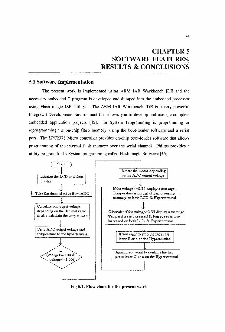
Fig 5.1: Flow chart for the present work
75
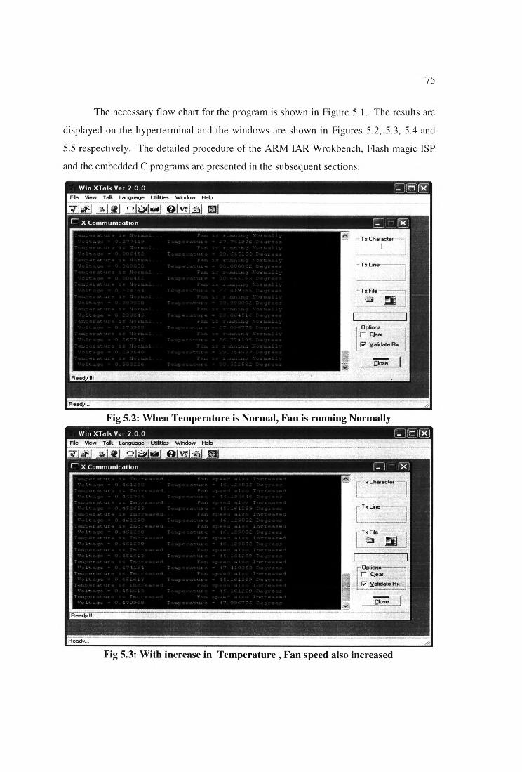
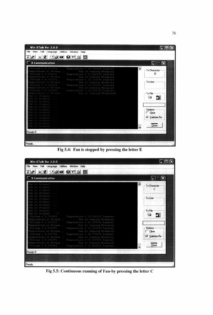
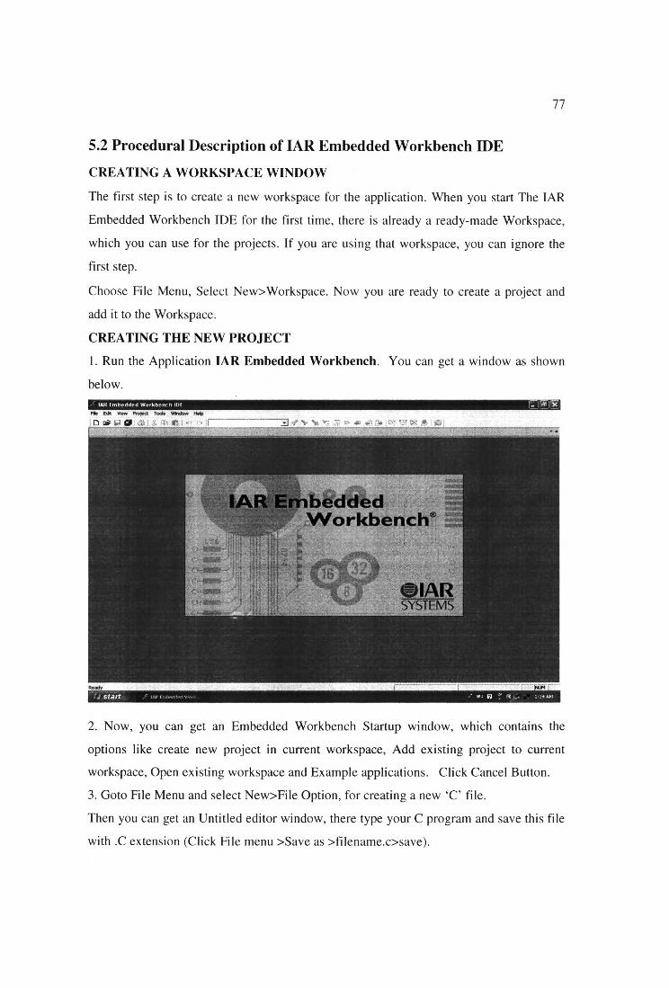
The necessary flow chart for the program is shown in Figure 5.1. The results are
displayed on the hyperterminal and the windows are shown in Figures 5.2, 5.3, 5.4 and
5.5 respectively. The detailed procedure of the ARM IAR Wrokbench, Flash magic ISP
and the embedded C programs are presented in the subsequent sections.
Fig 5.2: When Temperature is Normal, Fan is running Normally
Fig 5.3: With increase in Temperature , Fan speed also increased
76
Fig 5.4: Fan is stopped by pressing the letter E
Fig 5.5: Continuous running of Fan-by pressing the letter C
77
5.2 Procedural Description of IAR Embedded Workbench IDE
CREATING A WORKSPACE WINDOW
The first step is to create a new workspace for the application. When you start The IAR
Embedded Workbench IDE for the first time, there is already a ready-made Workspace,
which you can use for the projects. If you are using that workspace, you can ignore the
first step.
Choose File Menu, Select New>Workspace. Now you are ready to create a project and
add it to the Workspace.
CREATING THE NEW PROJECT
1. Run the Application IAR Embedded Workbench. You can get a window as shown
below./ IAR Embedded Workbench IDE r3!5Fte Ed* View Project Tools Window Help
.b«H0 » .. fc Kll '■« i.........................................................A-t V N= V; - ... *• i, ,• •• .» &
2. Now, you can get an Embedded Workbench Startup window, which contains the
options like create new project in current workspace, Add existing project to current
workspace, Open existing workspace and Example applications. Click Cancel Button.
3. Goto File Menu and select New>File Option, for creating a new ‘C’ file.
Then you can get an Untitled editor window, there type your C program and save this file
with .C extension (Click File menu >Save as >filename.c>save).
78
4. Goto Project Menu and select Create New Project option, for creating a new project.
Now, you can observe a Create New Project window, click OK. Then you can get a Save
as window, there type a name for the project and save.
ADD FILES TO THE PROJECT
5. For Adding files to the project, goto Project Menu, select Add Files option. You can
get an Add Files window, there select the files which you have to add (header files and C
files), click Open button.
6. For adding options to the project, goto Project Menu, select Options. You can get an
Option for node window. There in General options category, select the Target and give
the Device name (LPC2378) and core. Next in Linker category, select the Output option
and tick the Override default and replace the extension as .hex and enable the Other
option and select the intel-extended option in Output format dropdown box. Next select
the config option in the same Linker category and tick the Override default option and
type the path for LPC2378_Flash.xcl file and finally click OK button.
BUILTING THE PROJECT
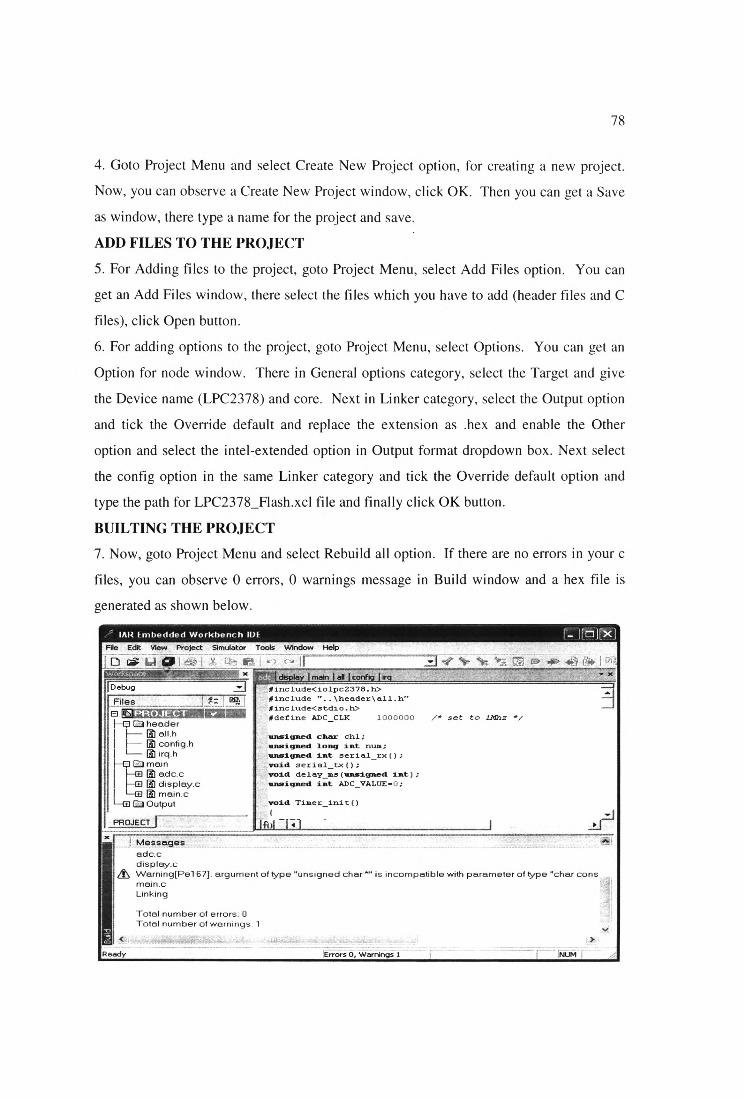
7. Now, goto Project Menu and select Rebuild all option. If there are no errors in your c
files, you can observe 0 errors, 0 warnings message in Build window and a hex file is
generated as shown below.
79
This hex file will be downloaded into the LPC2378 controller by Philips LPC 2000 Flash
Magic Software.
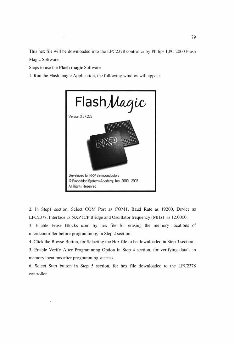
Steps to use the Flash magic Software
1. Run the Flash magic Application, the following window will appear.
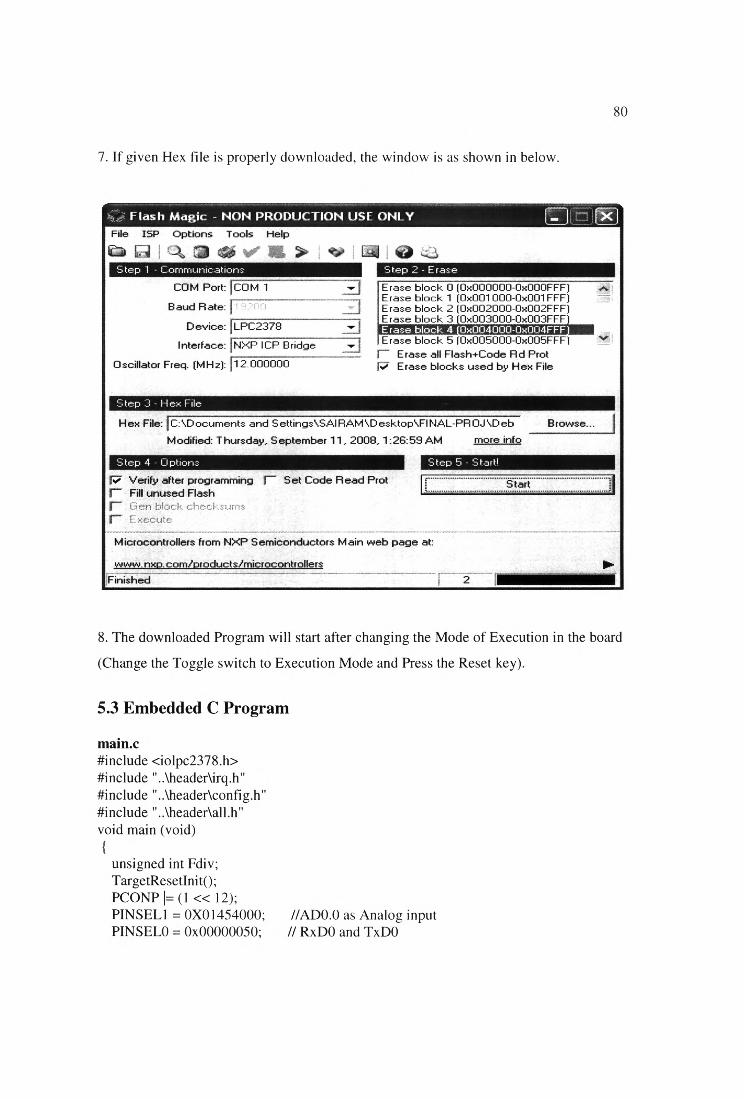
2. In Stepl section, Select COM Port as COM1, Baud Rate as 19200, Device as
LPC2378, Interface as NXP ICP Bridge and Oscillator frequency (MHz) as 12.0000.
3. Enable Erase Blocks used by hex file for erasing the memory locations of
microcontroller before programming, in Step 2 section.
4. Click the Bowse Button, for Selecting the Hex file to be downloaded in Step 3 section.
5. Enable Verify After Programming Option in Step 4 section, for verifying data’s in
memory locations after programming success.
6. Select Start button in Step 5 section, for hex file downloaded to the LPC2378
controller.
Version 3.57.223
Developed for NXP Semiconductors © Embedded Systems Academy, Inc. 2000 - 2007 All Rights Reserved
80
7. If given Hex file is properly downloaded, the window is as shown in below.
8. The downloaded Program will start after changing the Mode of Execution in the board
(Change the Toggle switch to Execution Mode and Press the Reset key).
5.3 Embedded C Program
main.c#include <iolpc2378.h>#include "..\header\irq.h"#include "..\header\config.h"#include "..\header\all.h" void main (void)
{
unsigned int Fdiv;TargetResetInit();PCONP |= (1 « 12);PINSEL1 = 0X01454000; //ADO.O as Analog input PINSEL0 = 0x00000050; // RxDO and TxDO
81
FI04DIR = OXFFOOOFFF; FI03DIR = 0X008000FF; IOODIR = 0X0021F0FF; IOIDIR = 0XFF000000;
ADOCR = ( 0x01 « 0) I(( 1000000 / ADC_CLK - 1 )« 8 ) j
// SEL=1,select channel 0~7 on ADCO // CLKDIV = Fpclk /1000000 - 1
(1 « 16 ) J //BURST = 0, no BURST, software controlled(0 « 17 ) j // CLKS = 0, 11 clocks/10 bits(1 « 21)j // PDN = 1, normal operation(0 « 22 ) | // TEST1:0 = 00( 1 « 24 ) j // START = 0 A/D conversion stops(0 « 27 ); // EDGE = 0 (CAP/MAT singal falling,trigger A/D conversion)
U0LCR = 0x83;Fdiv = ( 1000000/16)/ 19200; U0DLM = Fdiv / 256;UODLL = Fdiv % 256;UOLCR = 0x03;UOFCR = 0x07;
I2COCONCLR=Ox6C; I2C0CONSET=0x40; I2C0SCLH=110; I2C0SCLL=90; intlcdQ; clear_display();
// 8 bits, no Parity, 1 Stop bit // baud rate
/* DLAB = 0 *//* Enable and reset TX and RX FIFO. */
//Enable I2C.
while(l){
serial_tx();}
adc.c
#i nclude<iolpc2378.h> finclude "..\header\all.h"#include<stdio.h>#defme ADC_CLK 1000000 /* set to 1 Mhz */
unsigned char chi; unsigned long int num; unsigned int serial_rx(); void serial_tx(); void delay_ms(unsigned int);
unsigned int ADC_VALUE=0;
void Timer_init(){
TOTC =0;TOMCR = 3;TOPR = 59; // 60/(59+1) - 1 Mhz TOMRO = 1000000;TOTCR = 1;
}
unsigned int serialjrx(){
while(UOLSR&OX01){
ch 1 =UORBR; putchar(chl);
}retum(chl);}
void send_serial_data(unsigned char serial){
while((UOLSR & 0x20)—0);UOTHR = serial;
}int putchar(int ch)
{
if (ch == V){
while (!(UOLSR & 0x20));UOTHR = OxOd;}
while (!(UOLSR & 0x20)); return (UOTHR = ch);
)void breaks()
{FI03PIN = 0X00000000;}
void delay_ms(unsigned int i){unsigned int j; while(i->0)
{for(j=0;j<4500;j++);}
83
void adcJcdQ{float adc_voltage; unsigned int calc; clear_display();
start: while(l)
{
while((ADOGDR & 0X80000000)1=0X80000000);num = (AD0GDR»6)& 0x3ff; // convesion data holds AD0DR0[6] to
AD0DR0P5]adc_voltage=(nu m * 3.3)/1023;printf("\n Voltage = %f\t", adc_voltage);printff' Temperature = %f Degrees", adc_voltage *100);
if(adc_voltage >=0.00 & adc_voltage <=1.00){
calc= adc_voltage *100000;
Timer_init();FI03PIN = 0X00000005; while(T0TC!=calc);T0TCR = 0;Timer_init();FI03PIN = 0X00000000; while(T0TC 1=100000);T0TCR = 0;
if(adc_voltage <=0.35){elear_display();dis_border();display_string_s("TEMP IS NORMAL",3,22); display_string_s("FAN IS RUNNING ",5,24); display_string_s(" NORMALLY ”,7,26);
printff"\nTemperature is Normal..."); printf("\t Fan is running Normally");}else if (adc_voltage >0.35){clear_display();
dis_border();display_string_s("TEMP IS INCREASED",3,16); display_string_s("FAN SPEED ALSO ",5,24); display_string_s(" INCREASED ”,7,30);
84
printf("\nTemperature is Increased..."); printf("\t Fan speed also Increased");
serial_rx();if(ch 1 =='C' | ch 1 =='c')
{
goto start;}
elseif(chl~'E' | chl=='e')
{
while) 1){
breaks));clear_display();dis_border();display_string_s("FAN IS STOPPED",3,20); printf("\nFan is stopped ..."); delay_ms(500); serial_rx();
if)chl=='C' | ch 1 =='e’){
goto start;}
} //end of while } //end of if
} //end of if } //end of while
} //end of main
void serial_tx(){
unsigned long int Fdiv;UOLCR = 0x83; // 8 bits, no Parity, 1 Stop bitFdiv = ( 12000000 / 16 ) / 19200 ; //baud rate U0DLM = Fdiv / 256;U0DLL = Fdiv % 256;UOLCR = 0x03; // DLAB = 0U0FCR = 0x07; // Enable and reset TX and RX FIFO.while) 1){adc_lcd();
}
display.c
85
#include <iolpc2378.h> #include ”..\header\all.h" #include <string.h>#define X_ADRESS OxB8 #defme Y_ADRESS 0x40
int va,i;void busy_check(); extern char array 1 [ 10]; extern unsigned int vol 1 ,vol2;unsigned int col[] ={0x00, 0x00, 0X00, 0x00, 0x0c, OxOc, 0x00, 0x00, 0x00, 0x00}; unsigned int coll {] ={0x00, 0x00, 0X00, 0x00, 0x30, 0x30, 0x00, 0x00, 0x00, 0x00};
unsigned int Arr[]= { 0X00,Ox7e, 0x42, 0x42, 0x42, 0x3c,0X00,0x3c, 0x42, 0x42, 0x42, 0x24,0X00,0x00, 0x28, 0x28,0x28, 0x00,0X00,0x01,0x01, 0x7f, 0x01,0x01 };
char border_arr(1024]={0,254, 2,250, 30, 10, 10, 10, 10, 10, 10, 10, 10, 10, 10, 10,10,10, 10,10, 10, 10, 10, 10,10, 10, 10, 10, 10, 10, 10, 10,10,10, 10,10, 10, 10, 10, 10, 10, 10, 10, 10, 10, 10, 10, 10,10, 10, 10, 10, 10, 10, 10, 10, 10, 10, 10, 10, 10, 10, 10, 10,10, 10, 10, 10, 10, 10, 10, 10, 10, 10, 10, 10, 10, 10, 10, 10,10, 10, 10, 10, 10, 10, 30, 10, 10, 10, 10, 10, 10, 10, 10, 10,10, 10, 10,10, 10, 10, 10, 10, 10, 10, 10, 10, 10, 10, 10, 10,10, 10, 10, 10, 10, 10, 10, 10, 10, 10, 10, 10,250, 2,254, 0,0,255, 0,255, 0, 0, 0, 0, 0, 0, 0, 0, 0, 0, 0, 0,0, 0, 0, 0, 0, 0, 0, 0, 0, 0, 0, 0, 0, 0, 0, 0,0, 0, 0, 0, 0, 0, 0, 0, 0, 0, 0, 0, 0, 0, 0, 0,
0, 0, 0, 0, 0, 0, 0, 0, 0, 0, 0, 0, 0, 0, 0, 0,0, 0, 0, 0, 0, 0, 0, 0, 0, 0, 0, 0, 0, 0, 0, 0,0, 0, 0, 0, 0, 0, 0, 0, 0, 0, 0, 0, 0, 0, 0, 0,0, 0, 0, 0, 0, 0, 0, 0, 0, 0, 0, 0, 0, 0, 0, 0,
0, 0, 0, 0, 0, 0, 0, 0, 0, 0, 0, 0,255, 0,255, 0,0,255, 0,255, 0, 0, 0, 0, 0, 0, 0, 0, 0, 0, 0, 0,0, 0, 0, 0, 0, 0, 0, 0, 0, 0, 0, 0, 0, 0, 0, 0,0, 0, 0, 0, 0, 0, 0, 0, 0, 0, 0, 0, 0, 0, 0, 0,0, 0, 0, 0, 0, 0, 0, 0, 0, 0, 0, 0, 0, 0, 0, 0,0, 0, 0, 0, 0, 0, 0, 0, 0, 0, 0, 0, 0, 0, 0, 0,0, 0, 0, 0, 0, 0, 0, 0, 0, 0, 0, 0, 0, 0, 0, 0,0, 0, 0, 0, 0, 0, 0, 0, 0, 0, 0, 0, 0, 0, 0, 0,0, 0, 0, 0, 0, 0, 0, 0, 0, 0, 0, 0,255, 0,255, 0,0,255, 0,255, 0, 0, 0, 0, 0, 0, 0, 0, 0, 0, 0, 0,0, 0, 0, 0, 0, 0, 0, 0, 0, 0, 0, 0, 0, 0, 0, 0,
86
0, 0, 0, 0, 0, 0, 0, 0, 0, 0, 0, 0, 0, 0, 0, 0, 0, 0, 0, 0, 0, 0, 0, 0, 0, 0, 0, 0, 0, 0, 0, 0, 0, 0, 0, 0, 0,255, 0,255, 0, 0, 0, 0, 0, 0, 0, 0, 0, 0, 0, 0, 0, 0, 0, 0, 0, 0, 0, 0, 0, 0, 0, 0, 0, 0, 0, 0, 0, 0, 0, 0, 0, 0, 0, 0, 0, 0, 0, 0, 0, 0, 0, 0,255, 0,255, 0, 0, 0, 0, 0, 0, 0, 0, 0, 0, 0, 0, 0, 0, 0, 0, 0, 0, 0, 0, 0, 0, 0, 0, 0, 0, 0, 0, 0, 0, 0, 0, 0, 0, 0, 0, 0, 0, 0, 0, 0, 0, 0, 0,255, 0,255, 0, 0, 0, 0, 0, 0, 0, 0, 0, 0, 0, 0, 0, 0, 0, 0, 0, 0, 0, 0, 0, 0, 0, 0, 0, 0, 0, 0, 0, 0, 0, 0, 0, 0, 0, 0, 0, 0, 0, 0, 0, 0, 0, 0,127,64, 95, 80, 80, 80, 80, 80, 80, 80, 80, 80, 80, 80, 80, 80, 80, 80, 80, 80, 80, 80, 80, 80, 80, 80, 80, 80, 80, 80, 80, 80, 80, 80, 80, 80, 80, 80, 80,
};
0, 0, 0, 0, 0, 0, 0, 0, 0, 0,0, 0, 0, 0, 0, 0, 0, 0, 0, 0,0, 0, 0, 0, 0, 0, 0, 0, 0, 0,0, 0, 0, 0, 0, 0, 0, 0, 0, 0,0, 0, 0, 0, 0, 0, 0, 0, 0, 0,0, 0, 0, 0, 0, 0,255, 0,255, 0,0, 0, 0, 0, 0, 0, 0, 0, 0, 0, 0,0, 0, 0, 0, 0, 0, 0, 0, 0, 0,0, 0, 0, 0, 0, 0, 0, 0, 0, 0,0, 0, 0, 0, 0, 0, 0, 0, 0, 0,0, 0, 0, 0, 0, 0, 0, 0, 0, 0,0, 0, 0, 0, 0, 0, 0, 0, 0, 0,0, 0, 0, 0, 0, 0, 0, 0, 0, 0,0, 0, 0, 0, 0, 0,255, 0,255, 0,0, 0, 0, 0, 0, 0, 0, 0, 0, 0, 0,0, 0, 0, 0, 0, 0, 0, 0, 0, 0,0, 0, 0, 0, 0, 0, 0, 0, 0, 0,0, 0, 0, 0, 0, 0, 0, 0, 0, 0,0, 0, 0, 0, 0, 0, 0, 0, 0, 0,0, 0, 0, 0, 0, 0, 0, 0, 0, 0,0, 0, 0, 0, 0, 0, 0, 0, 0, 0,0, 0, 0, 0, 0, 0,255, 0,255, 0,0, 0, 0, 0, 0, 0, 0, 0, 0, 0, 0,0, 0, 0, 0, 0, 0, 0, 0, 0, 0,0, 0, 0, 0, 0, 0, 0, 0, 0, 0,0, 0, 0, 0, 0, 0, 0, 0, 0, 0,0, 0, 0, 0, 0, 0, 0, 0, 0, 0,0, 0, 0, 0, 0, 0, 0, 0, 0, 0,0, 0, 0, 0, 0, 0, 0, 0, 0, 0,0, 0, 0, 0, 0, 0,255, 0,255, 0,80, 80, 80, 80, 80, 80, 80, 80, 80, 80, 80,80, 80, 80, 80, 80, 80, 80, 80, 80, 80, 80,80, 80, 80, 80, 80, 80, 80, 80, 80, 80, 80,80, 80, 80, 80, 80, 80, 80, 80, 80, 80, 80,80, 80, 80, 80, 80, 80, 80, 80, 80, 80, 80,80, 80, 80, 80, 80, 80, 80, 80, 80, 80, 80,80, 80, 80, 80, 80, 80, 80, 80, 80, 80, 80,80, 80, 80, 80, 80, 80, 80, 95, 64,127, 0
unsigned char alpha[]= { 0X00,0x7c, 0x12, 0x12, 0x12, 0x7c, //A 0X00,65, 127, 73, 73, 54, //B0X00,0x3c, 0x42, 0x42, 0x42, 0x24, IIC0X00,0x7e, 0x42, 0x42, 0x42, 0x3c, //D0X00,0x7e, 0x4a, 0x4a, 0x4a, 0x42, //E
87
0X00,126, 0x0a, 0x0a, 0x0a, 0x02, //F0X00,Ox3C, 0x42, 0x42, 0x52, 0x70, //G0X00,Ox7e, Ox 10, Ox 10, Ox 10, Ox7E, //H 0X00,0x00, 0x42, 0x7E, 0x42, 0x00, HI 0X00,Ox7e, Ox 18, 0x24, 0x42, 0x00, HI 0X00,0x7e, Ox 18, 0x24, 0x42, 0x00, l/K 0X00,Ox7e, 0x40, 0x40, 0x40, 0x60, //L0X00,Ox7e, 0x04, Ox 18, 0x04, Ox7e, //M 0X00,Ox7e, 0x04, 0x08, Ox 10, Ox7e, /IN 0X00,0x3c, 0x42, 0x42, 0x42, 0x3C, I/O 0X00,0x7e, Ox 12, Ox 12, Ox 12, OxOc, IIP 0X00,Ox7E, Ox 12, Ox 12, 0x32, 0x4c, HQ 0X00,0x7E, 0x12, 0x12, 0x32, 0x4c, HR 0X00,0x24, 0x4a, 0x4a, 0x4a, 0x32, IIS 0X00,0x02, 0x02,0x7e, 0x02, 0x02, If!0X00,0x3E, 0x40, 0x40, 0x40, 0x3E, //U 0X00,Ox 1E, 0x20, 0x40, 0x20, Ox 1E, //V 0x00,126, 64, 120, 64, 126, //W0X00,195, 36, 24, 36, 195, HX0X00,0x06, 0x08, 112, 0x08, 0x06, HY 0X00,99, 81, 73, 69, 99 HZ
};
unsigned char space[]={ 0X00,0x00, 0x00, 0x00, 0x00, 0x00} ;
void display_string_s(unsigned char str[],unsigned char row,unsigned char col){
unsigned int start_pos=0,row_addr,col_addr; unsigned int Ioop,first_half=0,l,c,index=0;
start_pos = (col+63) - 64; // To Identify the Starting Location row_addr = 0xb8 + (row-1); col_addr = col+(64-1);
l=strlen(str);writecmd(row_addr); //Row Address writecmd(col_addr); //Col Address
for(loop=0;loop<l;loop++){
writecmd(row_addr); //Row Address for(first_half = 0; first_half<6;first_half++){
writecmd(row_addr); //Row Address writecmd(coLaddr); //Col Address
if(start_pos<64)
88
IOOCLR = 0X00010000; // CS2 DISABLED if((start_pos)==64){
IOOSET = 0X00010000; writeemd(row_addr); //Row Address writecmd(0x40); //Col AddressIOOCLR = 0X00008000;
}
if(start_pos>64)IOOCLR = 0X00008000; // CS2 DISABLEDc = str[loop];if(c==0x20){
index=(c-0x20)*6; writedata($pace[first_half+index]); start_pos = start_pos + 1; col_addr = col_addr+1;
}if(c>64){
index = (c-65)*6;writedata(alpha[first_half+index]); start_pos = start_pos + 1; col_addr = col_addr+l;
}
void busy_check(){
for(int i=0;i<0x30;i++);
void dis_border(){
unsigned int page,dat; for(page =0;page<8;page++)
{dat = page * 128 ; writecmd(0xB8+page); writecmd(0x40); write_main4(0x 10000000,dat);
writecmd(0xB8+page);writecmd(0x40);

write_main5(0x80000000,dat + 64);
void write_main4(unsigned long int cs,unsigned int col){
int i;IOOSET = CS1; H PAGE 1 IS SELECGTED.IOOCLR = CS2;for(i=col;i<(64+col);i+-i-)writedata(border_arr[i]);
}
void write_main5(unsigned long int cs,unsigned int col){
int i;IOOSET = CS2;IOOCLR = CS1; for(i=col;i<(64 +col);i++) writedata(border_arr[i]);
void clearpageQ{
IOOSET = CS2;IOOSET = CS1; for(int j=0xbb;j<0xc0;j++)
writecmd(j); writecmd(0x40); for (int y=0;y<64;y++) writedata(OxO);
}}
void writecmd(unsigned int ch){
IOOSET = 0X00018000; // CS 1 AND CS2 ENABLED busy_check();IOOCLR = 0X00200000; // RS = O I01CLR =0X10000000; // DIOW FI03PIN = ch;FI03SET = 0X00800000;FI03CLR = 0X00800000;
void writedata(unsigned int chi)
90
busy_check();IOOSET = 0X00200000; // RS = 0 I01CLR =0X10000000; //DIOW FI03PIN = chi;FI03SET = 0X00800000;FI03CLR = 0X00800000;
void pageclearQ
int i,y;IOOSET = 0X00018000; // CS1 AND CS2 WNABLED for(i=0xb8;i<0xc0;i++)
writecmd(i);writecmd(0x40);
for (y=0;y<64;y++) writedata(OxOO);
void clear_display()(
pageclear();}void intlcd(){
writecmd(0x3e);writecmd(0x3f);writecmd(OxcO);writecmd(0xb8);
}
Header files:
all.h
#define ADC_CLK 1000000 /* set to 1 Mhz */#define LCD EN 0X00800000#defme RS 0X00200000#define DIOW 0X10000000#defineCSl 0X00008000#define CS2 0x00010000
void dis_border(); int putchar(int ch); void serial_tx(void);
91
void write_main4(unsigned long int cs,unsigned int col); void write_main5(unsigned long int cs,unsigned int col); void display_string_s(unsigned char str[],unsigned char row,unsigned char col); void pageclear(); void clearpageQ; void clear_display(); void adc_serial_tx(unsigned int ch); void adc_lcd();void send_serial_data(unsigned char serial); void writecmd(unsigned int ch); void busy_check(); void writedata(unsigned int chi); void intlcdQ;
irq.h
* irq.h: Interrupt related Header file for NXP LPC2378 Family
#ifndef__IRQ_H#define _IRQJH
#define I_Bit 0x80 #define F Bit 0x40
#define SYS32Mode Ox IF #define IRQ32Mode 0x12 #define FIQ32Mode Oxll
#define HIGHESTJPRIORITY 0x01 #define LOWE8T_PRIORITY OxOF
#define WDT_INT 0 #define SWIJNT 1 #define ARM_COREO_INT #define ARM_COREl _INT #define TIMEROJNT 4 #define TIMER 1_INT 5 #define UARTOJNT 6 #define UART1JNT 7 #define PWM0_1_INT 8 #defme I2C0JNT 9 #define SPIOJNT 10 /*#define SSPOJNT 10 #defineSSPl_INT 11 #define PLLJNT 12
23
SPI and SSPO share VIC slot */
92
#define RTCJNT 13 #define EINTOJNT 14 #define EINT1_INT 35 #define EINT2JNT 16 #define EINT3 _INT 17 #define ADCOJNT 18 #define I2C1 _INT 19 #define BODJNT 20 #define EMAC _INT 21 #define USB _INT 22 #define CANJNT 23 #define MCLINT 24 #define GPDMAJNT 25 #define TIMER2JNT 26 #define T1MER3JNT 27 #defme UART2JNT 28 #define UART3JNT 29 #define I2C2 JNT 30 #define I2SJNT 31
#define VIC_SIZE 32
#define VIC_BASE_ADDR ((unsigned int)&VICIRQSTATUS)
#define VECT_ADDR_INDEX 0x100 #defme VECT_CNTLJNDEX 0x200
void init_VIC( void);long install_irq( long IntNumber, void *HandlerAddr, long Priority );
#endif /* end__IRQ_H */
End Of File
config.h
#if USE_USB /* 1 is USB, 0 is non-USB related *//* Fcck = 57.6Mhz, Fosc = 288Mhz, and USB 48Mhz */#defme PLL_MValue 11#defme PLL_NValue 0#define CCLKDivValue 4#define USBCLKDivValue 5
/* System configuration: Fosc, Fcclk, Fcco, Fpclk must be defined */
/* PLL input Crystal frequence range 4KHz~20MHz. */#define Fosc 12000000/* System frequence,should be less than 80MHz. */#define Fcclk 57600000 #define Fcco 288000000 #else
/* Fcck = 50Mhz, Fosc = 300Mhz, and USB 48Mhz */#define PLL_MValue 24 #define PLL_NValue 1 #defme CCLKDivValue 5 #define USBCLKDiv Value 6
/* System configuration: Fosc, Fcclk, Fcco, Fpclk must be defined *//* PLL input Crystal frequence range 4KHz~20MHz. */#define Fosc 12000000/* System frequence,should be less than 80MHz. */#define Fcclk 50000000 #define Fcco 300000000
#endif
/* APB clock frequence , must be 1/2/4 multiples of ( Fcclk/4 ). *//* If USB is enabled, the minimum APB must be greater than 16Mhz */#if USE_USB #define Fpclk (Fcclk / 2)#else#define FPCLK (Fcclk / 4)#endif
void init_VIC(void){
long i = 0;long *vect_addr, *vect_cntl;
/* initialize VIC*/VICINTENCLEAR = Oxffffffff;VICADDRESS = 0;VICINTSELECT = 0;
/* set all the vector and vector control register to 0 */ for (i = 0; i < VICJSIZE; i++ ){vect_addr = (long *)(VIC_BASE_ADDR + VECT_ADDR_INDEX + i*4); vect_cntl = (long *)(VIC_BASE_ADDR + VECT_CNTL_INDEX + i*4); *vect_addr = 0x0;
94
*vect_cntl = OxF;}return;
void GPIOResetInit( void){
/* Reset all GPIO pins to default: primary function */ PINSELO = 0x00000000;PINSEL1 = 0x00000000;PINSEL2 = 0x00000000;PINSEL3 = 0x00000000;PINSEL4 = 0x00000000;PINSEL5 = 0x00000000;PINSEL6 = 0x00000000;PINSEL7 = 0x00000000;PINSEL8 = 0x00000000;PINSEL9 = 0x00000000;PINSEL10 = 0x00000000;
IOODIR = 0x00000000;101 DIR = 0x00000000;
FIOODIR = 0x00000000;FIOIDIR = 0x00000000;FI02DIR = 0x00000000;FI03DIR = 0x00000000;FI04DIR = 0x00000000;
FIOOMASK = 0x00000000;FTOl MASK = 0x00000000;FI02MASK = 0x00000000;FI03MASK = 0x00000000;FI04MASK = 0x00000000;
return;}
void ConfigurePLL (void ){
long MValue, NValue;
if ( PLLSTAT & (1 « 25)){PLLCON = 1; I* Enable PLL, disconnected */ PLLFEED = Oxaa;PLLFEED = 0x55;
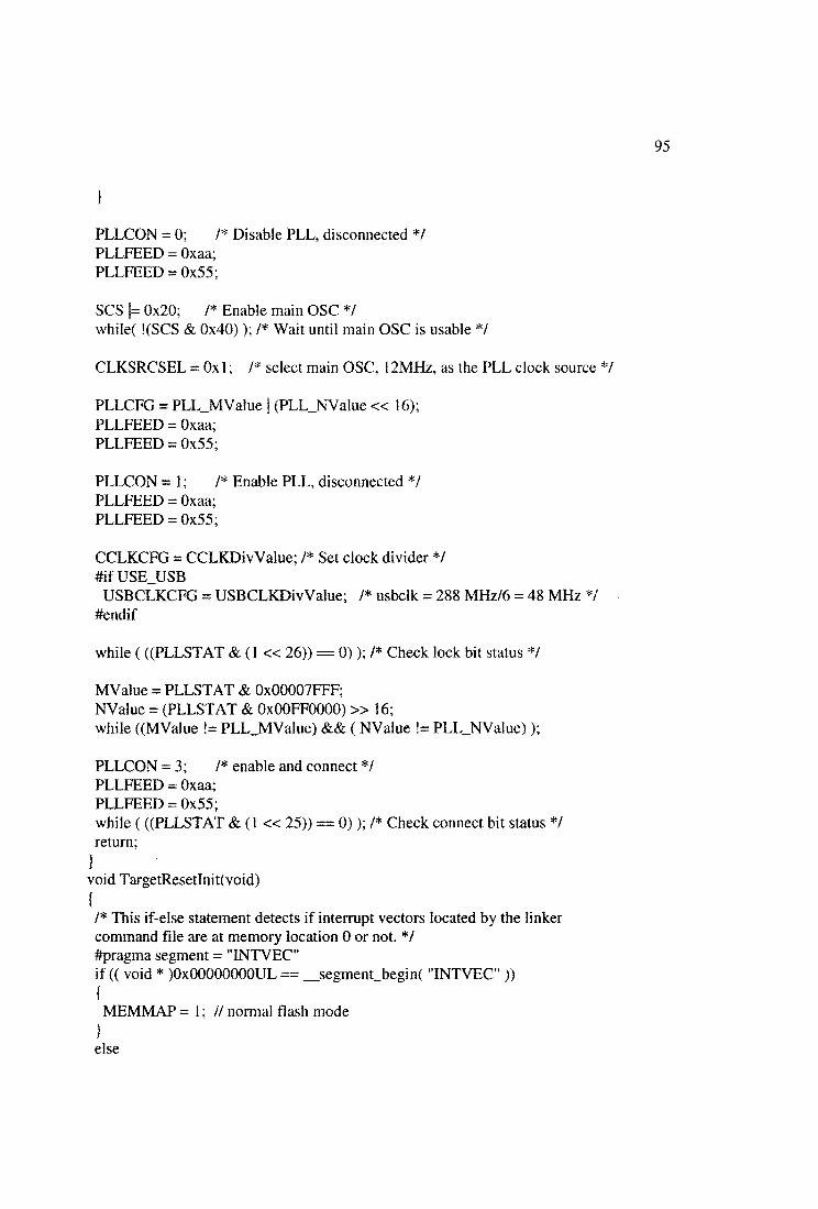
95
}
PLLCON = 0; /* Disable PLL, disconnected */PLLFEED = Oxaa;PLLFEED = 0x55;
SCS |= 0x20; /* Enable main OSC */while( !(SCS & 0x40)); /* Wait until main OSC is usable */
CLKSRCSEL = 0x1; I* select main OSC, 12MHz, as the PLL clock source */
PLLCFG = PLL_MValue | (PLL_NValue « 16);PLLFEED = Oxaa;PLLFEED = 0x55;
PLLCON =1; /* Enable PLL, disconnected */PLLFEED = Oxaa;PLLFEED = 0x55;
CCLKCFG = CCLKDivValue; /* Set clock divider */#if USE_USB
USBCLKCFG = USBCLKDivValue; /* usbclk = 288 MHz/6 = 48 MHz */ #endif
while (((PLLSTAT & (1 « 26)) == 0)); /* Check lock bit status */
MValue = PLLSTAT & 0x00007FFF;NValue = (PLLSTAT & OxOOFFOOOO) » 16;while ((MValue != PLL_MValue) && ( NValue != PLLJMValue));
PLLCON = 3; /* enable and connect */PLLFEED = Oxaa;PLLFEED = 0x55;while (((PLLSTAT & (1 « 25)) == 0)); /* Check connect bit status */ return;
}
void TargetResetlnit(void){
/* This if-else statement detects if interrupt vectors located by the linker command file are at memory location 0 or not. *1 #pragma segment = "INTVEC"if (( void * )0x00000000UL ==__segment_begin( "INTVEC")){
MEMMAP = 1; // normal flash mode}
else

{
MEMMAP = 2 ;// user ram mode - Map lowest 64 bytes of the address space to // bottom of internal RAM, moving exception vectors into place
#if USE_USBPCONP |= 0x80000000; /* Turn On USB PCLK */
#endif/* Configure PLL, switch from IRC to Main OSC */ ConfigurePLLQ;
/* Set system timers for each component */#if (Fpclk / (Fcclk / 4)) == 1
PCLKSEL0 = 0x00000000; /* PCLK is 1/4 CCLK */ PCLKSEL1 = 0x00000000;
#endif#if (Fpclk /(Fcclk/ 4)) == 2
PCLKSEL0 = OxAAAAAAAA; /* PCLK is 1/2 CCLK */ PCLKSEL1 = OxAAAAAAAA;
#endif#if (Fpclk /(Fcclk/ 4)) = 4
PCLKSEL0 = 0x55555555; /* PCLK is the same as CCLK */ PCLKSEL1 = 0x55555555;
#endif
/* Set memory accelerater module*/ MAMCR = 0;
#if Fcclk <20000000 MAMTIM = 1;
#else#if Fcclk <40000000
MAMTIM = 2;#else
MAMTIM = 3;#endif#endif
MAMCR = 2;
GPIOResetlnitQ;
init_VIC();
return;
97
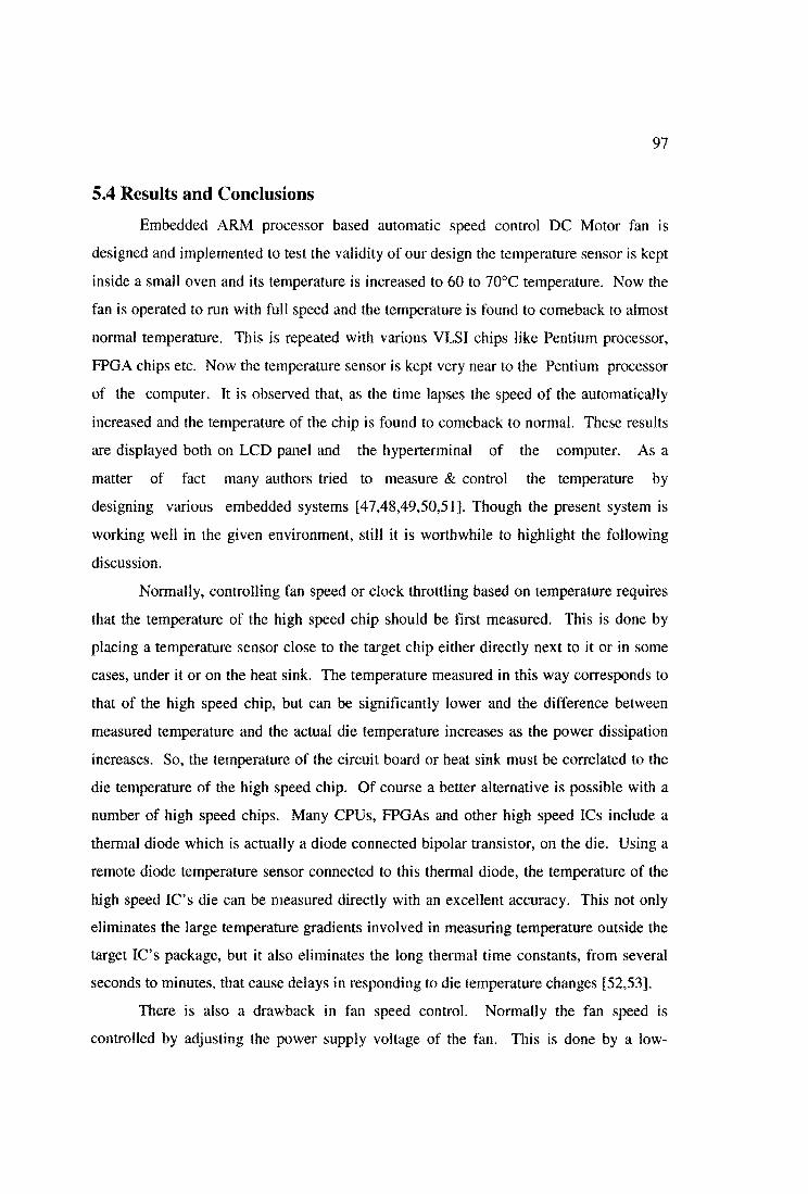
5.4 Results and Conclusions
Embedded ARM processor based automatic speed control DC Motor fan is
designed and implemented to test the validity of our design the temperature sensor is kept
inside a small oven and its temperature is increased to 60 to 70°C temperature. Now the
fan is operated to run with full speed and the temperature is found to comeback to almost
normal temperature. This is repeated with various VLSI chips like Pentium processor,
FPGA chips etc. Now the temperature sensor is kept very near to the Pentium processor
of the computer. It is observed that, as the time lapses the speed of the automatically
increased and the temperature of the chip is found to comeback to normal. These results
are displayed both on LCD panel and the hyperterminal of the computer. As a
matter of fact many authors tried to measure & control the temperature by
designing various embedded systems [47,48,49,50,51]. Though the present system is
working well in the given environment, still it is worthwhile to highlight the following
discussion.
Normally, controlling fan speed or clock throttling based on temperature requires
that the temperature of the high speed chip should be first measured. This is done by
placing a temperature sensor close to the target chip either directly next to it or in some
cases, under it or on the heat sink. The temperature measured in this way corresponds to
that of the high speed chip, but can be significantly lower and the difference between
measured temperature and the actual die temperature increases as the power dissipation
increases. So, the temperature of the circuit board or heat sink must be correlated to the
die temperature of the high speed chip. Of course a better alternative is possible with a
number of high speed chips. Many CPUs, FPGAs and other high speed ICs include a
thermal diode which is actually a diode connected bipolar transistor, on the die. Using a
remote diode temperature sensor connected to this thermal diode, the temperature of the
high speed IC’s die can be measured directly with an excellent accuracy. This not only
eliminates the large temperature gradients involved in measuring temperature outside the
target IC’s package, but it also eliminates the long thermal time constants, from several
seconds to minutes, that cause delays in responding to die temperature changes [52,53].
There is also a drawback in fan speed control. Normally the fan speed is
controlled by adjusting the power supply voltage of the fan. This is done by a low-
98
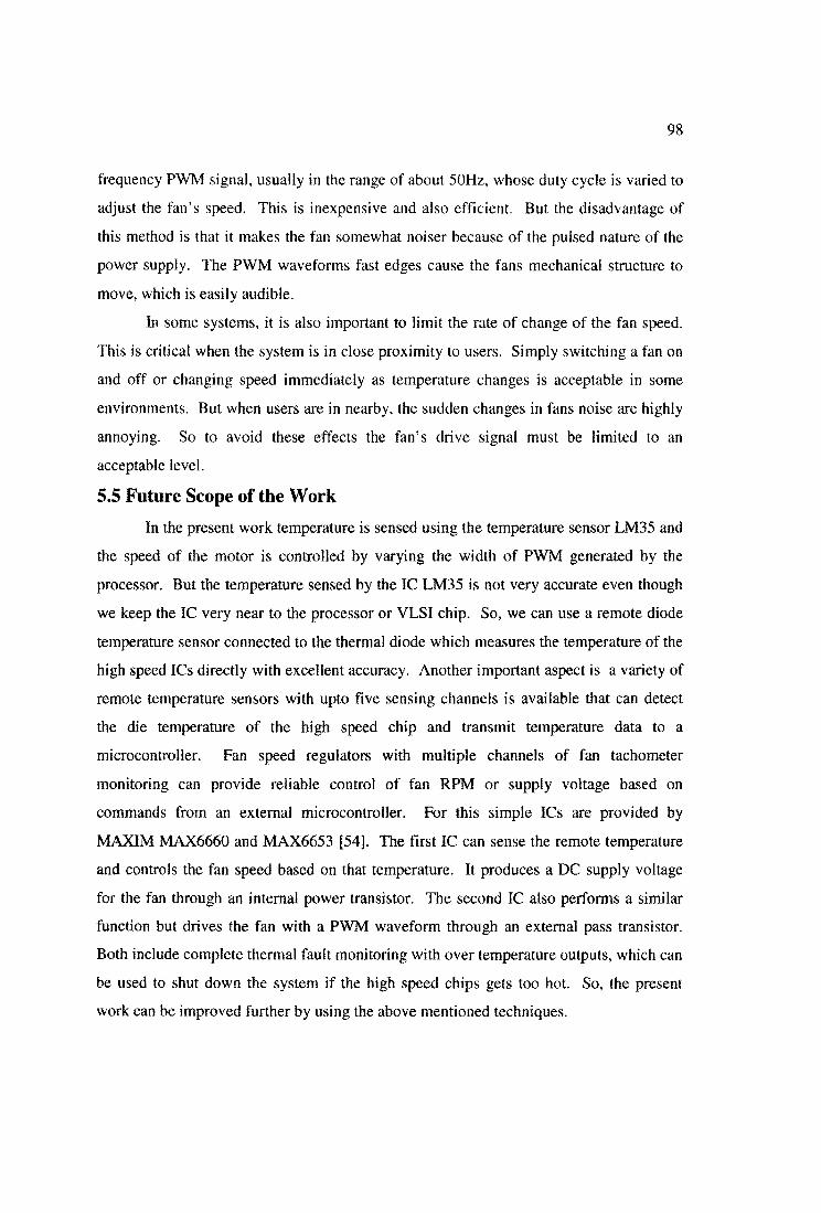
frequency PWM signal, usually in the range of about 50Hz, whose duty cycle is varied to
adjust the fan’s speed. This is inexpensive and also efficient. But the disadvantage of
this method is that it makes the fan somewhat noiser because of the pulsed nature of the
power supply. The PWM waveforms fast edges cause the fans mechanical structure to
move, which is easily audible.
In some systems, it is also important to limit the rate of change of the fan speed.
This is critical when the system is in close proximity to users. Simply switching a fan on
and off or changing speed immediately as temperature changes is acceptable in some
environments. But when users are in nearby, the sudden changes in fans noise are highly
annoying. So to avoid these effects the fan’s drive signal must be limited to an
acceptable level.
5.5 Future Scope of the Work
In the present work temperature is sensed using the temperature sensor LM35 and
the speed of the motor is controlled by varying the width of PWM generated by the
processor. But the temperature sensed by the IC LM35 is not very accurate even though
we keep the IC very near to the processor or VLSI chip. So, we can use a remote diode
temperature sensor connected to the thermal diode which measures the temperature of the
high speed ICs directly with excellent accuracy. Another important aspect is a variety of
remote temperature sensors with upto five sensing channels is available that can detect
the die temperature of the high speed chip and transmit temperature data to a
microcontroller. Fan speed regulators with multiple channels of fan tachometer
monitoring can provide reliable control of fan RPM or supply voltage based on
commands from an external microcontroller. For this simple ICs are provided by
MAXIM MAX6660 and MAX6653 [54]. The first IC can sense the remote temperature
and controls the fan speed based on that temperature. It produces a DC supply voltage
for the fan through an internal power transistor. The second IC also performs a similar
function but drives the fan with a PWM waveform through an external pass transistor.
Both include complete thermal fault monitoring with over temperature outputs, which can
be used to shut down the system if the high speed chips gets too hot. So, the present
work can be improved further by using the above mentioned techniques.