111Pbretronicein me...avms cie1 unsas 64101 tel 111 111 1122 41111 113 111(111111. 111 2114...
62
4 mpg AP,- 111Pbretronice in me Servicing RCA AGC Prevent Costly Callbacks Faster TV Repairs ctronlic SelfFebric,1974i0cengts
Transcript of 111Pbretronicein me...avms cie1 unsas 64101 tel 111 111 1122 41111 113 111(111111. 111 2114...

4mpgAP,-
111Pbretronicein me
Servicing RCA AGCPrevent Costly CallbacksFaster TV Repairs
ctronlic SelfFebric,1974i0cengts

AELECTRONICS, INC.
ALSO AVAILABLE IN .
...101 Tast 8 hr. Service!
$9951 YEAR GUARANTEE
All PTS BRANCHES are wholly owned subsidiaries of PTS ELECTRONICS, INC. (NO FRANCHISES!) andreport directly to the Home Office in Bloomington, Indiana. Only this way can we guarantee the samequalit?-PRECISION TUNER SERVICE-that made PTS the leader in this field.PTS is proud to be the only tuner service to publish a TUNER REPLACEMENT PARTS CATALOG (80 pagesof tur er blow-ups, tuner -antenna coil -and shaft replacement guides available for $1.00).
WE OFFER MORE. SERVICE IS EVERYTHING WITH US.WE ARE DYNAMIC AND FAST. TRUSTWORTHY.
*ea and - ;V 7teee Pevrbeeiudeft
ELECTRONICS, INC. isrecommended by more TV manufacturersand overhauls more tuners than all othertuner services combined!
for finer faster PrecisionTuner Service Send
Color Black & White TransistorTubes Varactor Detent UHF
All Makes
VHF, UHF or FM $9.95UV -COMBO 16.95IF-SUBCHASSIS 12.50
Major parts and shippingcharged at cost.
(Dealer net!)
over 4000 exact tuner replacementsavailable for $14.95 up (new orrebuilt)
faulty unit with tubes, shields and all broken parts to
1 TECTRON1CS INC
1111114W-110111 0/11a,ITS 11101110NiCS 1112
PO 1111 / 2
11.0011161014 WO 414011E1 112 174 4131
INICTINNI ULINNINATElICTWIRKS
PI 1111 41344SACLIANTO CAM 04041WI 116 41/ 6221
$011T0E1I CALIFORNIA,ITS ELECTRONICS INC
PO 400 1/14SAW 11160 2414 11105Ill III 111 1111
PIS 810111110. R.Fl. Ill III
Cal. INV111 1(3 423.111
Relleks113 11E211041M INC
IT 0 40I 1171IACRSONVILE Ill 11710EEL 104 010 1141
MINIM!21161111111C3. MC.
PS 1111 1121311111111N. 111 41111121. II?, 1244331
K UMASIPTS ELECTRONICS INC
1111 1111111411 ENE
AVMS CIE1 UNSAS 64101TEL 111 111 1122
41111113 111(111111. 1112114 IRIC1111161 NK IWI. IA 11113
221 404 1152041
NAItYLAIN.PTS ELEC1104iC3 INC
1101 SUM SI511V14 SUMS 40 10110III 101 161 0071
NIASSA00S11714ITS ILECT141113.
PI NI 3111SPIIINISI. NIA. 11111III 431 114.213/
11111113030111$ EUCTIONICS INC
115 N LAM ST
MINEWAPOLIS WNN 11401TEL 612 174 2131
11041.4PIS IlICTIMICS. MIC3111 IMAM INYEAS CM NMI 11110Ill. 111. 1111112
NOW 30010PTS RECTIONICS INC
101 MANOR ST1111410 IT 14217
Ili 116 111 4031
NW RESIT - IL T. aTTRiCtItIlICS. MC.
MI UNIT II.0. PARINI (I 17412111. III III 13MOT413 (1101041031612 VAN 40CLEttLao moo 44134TEL 716 145 4410
INLAID'S&11121111112C3, MC
P I NI 11511NUNN C1n. NU. 13111111 445 141 7113
1:9613411RECTIONICS INC
40 ID 13016P0111441 0116014 11711III 101 212 NH
PINRMIPANIA.41S (lICTIONICS. ICP.I 11151
PEURLPIIII. PA 11142
RI 215, 1241111
P10 1103110111124 INC
PO III 4130PiTTSBIRGII PA 11702
TIE 417 761 /641
MIAS.113 Manila NCP.I. NI 13321111111211. III. /5611RI. 214. 1114314
PTS ELECTRONICS INC
PO 10/ 16616INTISTON lix 11137TEL 113 144 4113
113111111CTON.
PTS ELECTRONICS INC
Ills 3/1146 ST
011001 SPRINGS WI 11010TEL 111 161 11131
For More Details Circle (1) on Reply Card

INDEXIntegrated Circuit Replacement Guide by Part ManlierIntegeoled Circuit Replacement Guide by Equipment
ManufacturerAdmirelAutomatic ReditaBondi. (Auto Recie)Cheyekin (Auto Radio)Curti. MathesDelco (General Motors)ElectrohomefatherGerm* Electric14eathititH. M. ScottnitMagnavoxMeninxMc InnenMotoristsPacIterd-11111/TMedyne
Rome enfilflifIn1001 ProskieWAutomobile Radio
RCASeanSylvaniaVoice 01 Stualc (V-1111)goiterWelle-CionflnerZenIth
Imported -IC- Replacement ChideAuto Radio KitMotor Brand Morrie Entertainment KM
2
SYLVANIA
Csemiconductors
Here's one book you can really tell by its cover.We clDn't have to waste time telling you about our new integrated circuit replacement guide.
Just read the index on the cover.If that doesn't convince you, nothing will.
Available from your local Sylvania distributor.Sylvania Electronic Components, 100 First Ave., Waltham, Mass. 02154
Lad SYLVANIAFebruary, 1974/ELECTRONIC SERVICING 1
February, 1974 L. Volume 24, No. 2
Electronic Servicing,
idtir love 14 Electronics ... Medicine's Liveliest Helper-more information
about the fast-growing field of medical electronics-Joseph J.Carr. CET.
22 Shortcuts For Servicing AGC In RCA Portables-substitutionof AGC bias for transistors must be done correctly to avoiddamage, and yet obtain useful test data-Lawrence Bowen.
28 Faster Repairs Of Those TV "Dogs"-logical tests based oncircuit actions make diagnosis of the tough sets much easier-Robert L. Goodman. CET.
34 Signature Patterns-in-circuit curve -tracer tests of transistorsused in Sylvania E03, E04 and EO5-Jud Williams, CET.
44 Prevent Those Costly Callbacks-invest a few extra momentsduring each repair job to spot weak components before theyfail-John Rozsa and Carl Babcoke.
46 Record Changer Workshop, Part 4-the workings of aprecision turntable are detailed in pictures-Forest H. Belt,CET.
DEPARTMENTS
Electronic Scanner 4 Test Equipment 51Symcure 8 Product Report 53Troubleshooting Tips 10 Catalogs and Literature ....54Reader's Exchange 12 Photofact Bulletin 57
Advertiser's Index 58
Second class postage paid at Shawnee Mission, Kansas and additional mailing offices.Published monthly by INTERTEC PUBLISHING CORP., 1014 Wyandotte St., Kansas City,Mo. 64105. Vol. 24, No. 2. Subscription rate $6 per year In U.S., Its possessions andCanada; other countries $7 per year. Send Form 3579 to 9221 Oulyira Road, ShawneeMission, Ks. 66215.
Copyright, 1974, Howard W. Sams & Co., Inc. All Rights Reserved: Material may not bereproduced or photocopied In any form without written permission of publisher.
EDITORIALRONALD N. MERRELL, Director
CARL H. BABCOKE, Managing EditorLESLEE ANDERSON, Editorial Assistant
WEBB G. STREIT, Graphic Designer
CONTRIBUTING AUTHORSLawrence BowenJoseph J. CarrWayne Lemons
Robert G. Amick
TECHNICAL CONSULTANTJOE A. GROVES
EDITORIAL ADVISORY BOARDLES NELSON, Chairman
Howard W Sams & Co., Indianapolis
CIRCULATIONEVELYN ROGERS, Manager
ADVERTISING SALESKansas City, Missouri 64105
Tele: 913/888-4664E. P. LANGAN, Director
R. J. HANCOCK, ManagerJAKE STOCKWELLRON ROBINETTE
GREG GARRISON , Production
REGIONAL ADVERTISING SALES OFFICESIndianapolis, Indiana 46260
ROY HENRY2469 E. 98th St.
Tele: 317/846-7026
New York, New York 10017STAN OSBORN
Room 122760 E. 42nd St.
Tele. 212/687-7240
Los Angeles, California 90006MIKE KREITER
3600 Wilshire Blvd., Suite 1510Tele: 213/383-1552
London W. C. 2, EnglandJOHN ASHCRAFT & CO.
12 Bear StreetLeicester SquareTele: 930-0525
Amsterdam C. HollandJOHN ASHCRAFT & CO.W. J. M. Sanders, Mgr.for Benelux & Germany
Herengracht 365Tele: 020-240908
Tokyo, JapanINTERNATIONAL MEDIAREPRESENTATIVES LTD.
1, Shiba-Kotohiracho, MinatokuTele: 502-0656
.0
ELECTRONIC SERVICING (with which lacombined PF Reporter) Is publisnedmonthly by Intertec Publishing Corp.,1014 Wyandotte Street, Kansas City,Missouri 64105.
Subscription Prices: 1 year - 56.00, 2years - $10.00, 3 years - $13.00, in theU.S.A. Its possessions and Canada.
All other foreign countries: 1 year -S7.00, 2 years - $12.00, 3 years -$16.00. Single copy 75c; back copies $1.Adjustment necessitated by subscription
termination at single copy rate.
Robert E. Hertel, Publisher
Intertec Publishing Corp.Subsidiary of Howard W. Sams & Co.,Inc
2 ELECTRONIC SERVICING/February, 1974

ONE TV Repair Shop in your lo-cality .. . will soon stand out headand shoulders above every othercompetitor in town. It could beYOU.
Wont to know HOW? Very simply:
by using a regular series of clever, inex-pensive 'column' ads in your local news-paper! You doubt it? Well . . .
. . . A TV shop in Maryland hadto hire more help within 3 weeks afterstarting their series!. . . A dealer in Montreal has hadpeople come in from all over Canada,from his ads.
. . An enterprising repair man inLouisiana has acquired 4 other placesin his area from the surge of busi-ness that his series brought.. . . Two cousins in a New Englandcommunity attribute 75% of theirbusiness to these ads.
You can see their secret . . . adapt theirmethod . . . improve your business ...gain an immediate edge on competition. . . and develop a friendly, permanentclientele . . . by judiciously using thesame inexpensive idea!
Our new folio-which we'd like youto try out for six months-is called"How to Double Your Business withUnique 'Column' Ads."
It shows how others have done it . . .
replete with case histories.It shows how you can do it, too.It shows how and when, where andwhy-the whole fascinating story ofthis cheapest means of advertising ...with most effective RESULTS! Hereare ads that will attract attention-stimulate curiosity . . . arouse inter-est, amuse readers and make YOUknown and remembered for quality. . . service ... integrity . . . de-pendability.
All at trivial cost!Among the Advantages you will learn
. . . how to create interest amongprospects who never even knew youexisted!. . . how to influence people to switchover to your business or service!. . . how to create excitement-eventhough your business seems dull anddrab!. . . how to get the most out of yourpromotional dollar (something mostbusiness men never learn!). . . how to get your customers to"work" for you!. . . how to get fast action from a $3investment!. . . how to keep interest sustainedover an extended period!. . . how to make people laugh . . .
and agree with you... and seek tomeet you personally!. . . how to get maximum assistancewithout charge from the newspaperstaff!. . . how to develop continuing ideas!
And. obey, all -
A Special "TV REPAIR" PROMOTIONSUPPLEMENT!
H. K. SIMON ADVERTISINGBOX 236
HASTINGS -ON -HUDSONNEW YORK 10706
"TV REPAIR" PROMOTION SUPPLEMENT -
shows you:
... How to out -smart (instead of out -spend) the competition!
... Why most ads fail . . .
The ONE BIG SECRET of successful TV Repair advertising.... The Greatest Compliment any ad can Pay You.... The mistake that is made by 98 out of 100 local advertisers.... 94 examples of enticing "come on in" copy (distilled from thousands).... 26 Merchandising Ideas that you can adapt, to stimulate business.... 37 Illustrations that enliven the ad, attract the eye.
Here are "Big Time" ideas at "small time" prices. Prepared by a $25,000 copygroup . . . but your cost is less than 400 per week!
You'll refer to this for years-every time you need copy to promote specialoccasions . . . or an idea for a layout . . . or an eye-catching border . . .
or a good illustration!You'll see how to establish your name as an outstanding source: as helpful
. . . friendly . . . sincere . . . intelligent ... courteous . . . dependable.
You'll see how to have people looking forward to your ads-wondering whatyou will say next!
You run very little risk, if you accept this opportunity-because we GUARAN-TEE that any one using these ideas six months or more who does NOT hearfavorable comment-who does NOT think his own staff has been stimulated-who does NOT see direct results at lower cost-can simply say so, and we'llREFUND 100% of every penny you paid us!
We think this offer is unique We dare to make it only because we KNOWthis will prove profitable to you.
Who in your community will benefit by this? Will YOU? Better advise usat once.
Write or wire us TODAY. Use the handy blank below.
Suppose YOU spent 3 weeks with an advertising agency ...
. . . developing o year's program for your business that would make you well known --giveyou a competitive edge . . . bring customers to your door . . stimulate your sales . .
save wasted efforts on unproductive promotion.Personal service, of course, is expensive. The ad agency's fee would be about $2,000, plus
your traveling and maintenance expenses.But we have completed just such an intensive 3 -week conference . . . and you may have theresults for a tiny fraction of that cost!
Let me ask: how is your present ad program going-now? Was it prepared well in advance,by a "pro"? Or do you promote your services, catch -as -catch -con, when you can spare a
moment?The difference between the two methods can mean a doubling of your annual gross.
Perhaps you've always thought, "I can't afford a high-priced ad man."But surely, you COULD afford him if he cost you only 40f a week/And if that 40$ weekly expense brought you $7,500 a year-you couldn't afford to be withouthim/"True", you say, "IF it is so good os all that."
We think it Is. But we want YOU to be the judge.Try the ideas for the next six months. Then -6 months from now-If you don't expect to getback at least $1,995 for your $19.95 Investment (a return of 100 to 1-or better) simply sendit back for full refund.Could anything be fairer?Since there's no obligation, why not accept? Promotion -who, I doubt If you'll EVER gist an-
other opportunity to equal It. But . .
Better act TODAY. This offer may be withdrawn when our supply of copies run out. So writ.or wire NOW!
rH. K. SIMON, Advertising Co.Box 236, Digit ES -44Hastings -on -Hudson, N. Y. 10706
Kindly send "HOW TO DOUBLE YOUR BUSINESS WITH UNIQUE 'COLUMN' ADS"along with your "TV REPAIR" PROMOTION SUPPLEMENT to:
NAME
ADDRESS
CITY, STATE
ZIP
We enclose our check for $19.95.
It is understood that if we use your ideas for six months or more and are not fullysatisfied, every cent will be refunded.
REFERENCES: Any publication in the U.S.A. Rated by Dun IL Bradstreet
L
For More Details Circle (5) on Reply Card
February, 1974/ELECTRONIC SERVICING 3

]11]111,ogielcimiernews of the industry
A1111111111111111111111111111M1
If you want to record a message in noisy surroundings, such as a factory floor,then talk through your ears. Sound crazy? It's true according to Battelli Institutein Frankfurt, as reported in the Kansas City Star. After months of tests, Germanscientists discovered that a minimicrophone worn in the ear picks up less noisethan a mike held close to the mouth. The principle is that when you talk some ofthe sound is carried through the skullbones to the ear. The scientists invited 15men to use ear mikes in a busy airplane hangar. All recorded messages amid theracket, and each recording was completely free of background noise.
Grundig By Amerex Electronics, Inc. has announced what company officialsbelieve to be the industry's first life -time guarantee covering transistors. TheGrundig Life -Time Guarantee applies to all transistors in every Grundig productcategory for as long as that instrument is with its original owner. Labor isadditional, unless covered by the original first -year free -labor warranty.
PTS Electronics, Inc. has formed a manufacturing division to develop andmanufacture Tuner Analysts. Port -A -Tuners, and related electronic devices. Thenew facility will be located adjacent to the home office division in Bloomington,Indiana.
Major Electronics Corp. has acquired from National Union Electric Corp. theexclusive rights to manufacture and market home -electronics products under theEmerson brand name. According to Merchandising Week, the agreement withNational Union limits Major's rights to the United States and Canada. TheEmerson label will be used on all Major home -entertainment products includingstereo components. phonographs, compacts, tape recorders and radios. Airconditioners and other appliances will continue to be produced and marketed byNational Union through its Emerson Quiet Kool division.
A new idea for sending identical messages to a small, select group has beenintroduced by Tape Reproductions Corp. Instead of being dictated in the usualletter, the message is recorded on a cassette, permitting the executive orprofessional to express his own personality, placing emphasis where needed, anddeveloping the story in much greater detail. The original cassette is thenduplicated within 24 hours of receipt by Tape Reproductions. To speed themessages, each cassette will be mailed directly to the end user if a set of addressedlabels or a mailing list is supplied with the original tape. Duplicate cassettes areavailable in lengths from fifteen minutes to two hours.
(Continued on page 6)
4 ELECTRONIC SERVICING/February, 1974
1 @©EP04`11C1PROVIDES YOU WITH ACOMPLETE SERVICE FORALL YOUR TELEVISIONTUNER REQUIREMENTS.
VHF Or UHF Any Type $9.95.UHF/VHF Combo $15.00.
In this price all parts are included, tubes,transistors, diodes, and nuvistors are chargedextra. This price does not cover mutilatedtuners.
Fast efficient service at our convenientlylocated service centers.
All tuners ultrasonically cleaned, repaired,realigned and air tested.
Universal Replacement Tuner $9.95 In Canada $14 351
This price buys you a complete new tunerbuilt specifically by SARKES TARZIAN INC.for this purpose.
All shafts have a maximum length of 101/2'which can be cut to 11/2".
Specify heater type parallel and series450mA or 600mA.
CUSTOM IZOWCustomized tuners are available at a cost of
(In Canadaonly $15.95; (with trade-in $13.95) $17 951$15 95)
Send in your original tuner for comparisonpurposes.
TSC
WATCH USGROW
HEADQUARTERS BLOOMINGTON, INDIANA 47401 537 S. Walnut Street Tel. 812-334.0411
ARIZONA TUCSON.ARIZONA 85713 1528 So. 6th Street, P.O. Box 4534 Tel 602-791-9243
CALIFORNIA NORTH HOLLYWOOD,CALIF. 91601 10654 Magnolia Boulevard Tel. 213.769-2720BURLINGAME,CALIF. 94010 1324 Marten Road Tel. 415-347-5728MODESTO,CALIF. 95351 123 Phoenix Avenue Tel. 209.521-8851
FLORIDA TAMPA,FLORIDA 33606 1505 Cypress Street Tel. 813-253-0324
GEORGIA ATLANTA,GEORGIA 30310 938 Gordon Street S.W Tel. 404.758.2232
ILLINOIS CHICAGO, ILLINOIS 60621 737 West SSth Street Tel. 312-873-5556-7SKOKIE.ILLINOIS 60076 5110 West Brown Street Tel. 312-675-0230
INDIANA HAMLMOND,INDIANA 46323 6833 Grand Avenue Tel. 219-845-2676INDIANAPOLIS, INDIANA 46204 817 North Pennsylvania St Tel. 317.632.3493
KENTUCKY IOUISVILLE,KENTUCKY 40208 2920 Taylor Boulevard Tel. 502.634.3334
LOUISIANA SHREVEPORT. LOUISIANA 71104 3025 Highland sve. Tel. 318-861-7745
MARYLAND BALTMIORF.MD. 21215 5505 Reistertown Rd., P.O. Box 2624 ...Tel. 301-358-1186
MISSOURI ST. LOUIS, MISSOURI 63132 10530 Page Avenue Tel. 314.429-0633
NEVADA LAS VEGAS.NEVADA 89102 1412 Western Ave. No. 1 Tel. 702-3844235
NEW JERSEY JERSEY CITY NEW JERSEY 07307 547-49 Tonnek Avenue HWY 189 ....Tel. 201.792-3730TRENTON,NEW JERSEY 08638 901 N. Olden Ave Tel. 609-393-P999
OHIO CINCINNATLOHIO 45216 7450 Vine Street Tel. 513-821-5080
CLEVELAND,OHIO 44109 4597 Pearl Road Tel. 216.741.2314
TOLEDO,OHIO 43624 119 North Erie Street Tel. 419.243.6733
OREGON PORTLAND,OREGON 97210 1732 N.W. 25th Avenue Tel. 503-222-9059
TENNESSEE GREENEVILI F TENNESSEE 37743 1215 Snapp* Ferry Road Tel. 615.639-8451
MEMPHIS, TENNESSEE 38111 3158 Barron Ave. Tel. 901-458-2355
TEXAS DALLAS,TEXAS 75218 11540 Garland Road Tel. 214.327-8413
VIRGINIA NORFOLK.VIRGINIA 23502 4538 East Princess Anne Rd. Tel. 703-855-2518
CANADA ST. LACR1. 's I MONTREAL,QUEBEC H4N-2L7 305 Decarir Tel. 514-748-8803
FOR INFORMATION ON FRANCHISE. CONTACT HEADQUARTERS
For More Details Circle (6) on Reply Card
February, 19741 ELECTRONIC SERVICING 5

news of the industry (Continued from page 4)
In the past, most picture tubes were designed for operation without X-radiationdanger up to 25 KV. Now, at least two models of TV chassis generate up to 30KV, and special glasses are used in the picture tube to minimize any radiation. Ifyou operate one of these chassis on your test jig, you don't have the protection. Werecommend the test tube in each jig be exchanged for one of this new type.
RCF Development is seeking licensees for a new television projection system whichuses no phosphors, according to Home Furnishings Daily. Invented and patentedby Edgar Price, the system features a bundle of optic fibers arranged in a straightline to project the TV image onto a rotating prism. The prism scans the image,which is then projected to a screen. Color and brightness are said to be improvedby the elimination of phosphors. The system operates by using lower voltages, withreduced radiation problems. Modulated Optical Fibers, Inc. has been formed tohandle sales and licensing.
The Consumer Product Safety Commission intends to develop safety rules coveringportable television sets. It is asking for information on television danger potentialsand will give public notice of hearings to develop safety standards. According toHome Furnishings Daily, nearly 100,000 sets in the past few months have beenfound by the commission to pose potential fire and shock hazards. There is "aproblem of pretty good size" with the TV sets said Commission Chairman Richard0. Simpson, but the CPSC has not determined what all the problems are. Simpsonwarned manufacturers and retailers that failure to report product hazards found infactory or store could result in severe legal and civil penalties. During the pastyear, CPSC field offices have surveyed fire marshalls in three counties in each oftheir areas for cases where television was the suspected cause of fires. Simpsonstated that the regional offices produced 914 reports of suspected TV -related firesin 42 inquiries. "I think we have enough evidence to be persuasive," he said.
Montgomery Ward is recalling 52,000 of its Airline -brand 23 -inch color consolesand TV/stereo combinations. A company spokesman said they might have circuitdefects that "under a combination of circumstances could create an electricalshock hazard." Most of the potentially -defective sets were sold in the fall of 1969,but only recently was it discovered that some models were missing a resister.Montgomery Ward has not received any field reports of consumers sufferingelectric shocks.
6 ELECTRONIC SERVICING/February, 1974
Here's everythingyou'd expect from a high-priced
signal generator.
Except a high price.
Our new B & K Model 2050 Solid-state RF SignalGenerator has features other companies chargemuch more for. Look at our specs: 100% Solid-state silicon circuitry with FET's in RF and audiooscillator stages. 6 bands with 1.5% accuracyfrom 100 kHz to 30 MHz. 3 outputs: RF, modu-lated RF (400 Hz), and externally modulated RF.Positive anti -backlash dial drive. Zener-regulatedpower supply. You needn't pay high prices forversatility, accuracy and reliability-now there'sthe Model 2050. And that's just what you'd ex-pect from B & K.
Contact your distributor, or write DynascanCorporation.
AU Very good equipment at a very good price.Dynascan Corporation1801 West Belle Plaine Avenue Chicago. Illinois 60613
You'd probably expect aportable oscillosope as rugged and
reliable as this one to cost a lot.
You'd be wrong.Introducing the B &K Model 1403 3" Solid-stateoscilloscope. It's so compact, reliable, and inex-pensive that it's the perfect scope for most on -the -line monitoring applications. Look at its specs:DC to 2MHz bandwidth at 20mV/cm. Recurrentsweep speeds from 10Hz to 100KHz. New wide-angle CRT to reduce case depth to a minimum.Direct -deflection terminals for waveforms up to150 MHz. Weighs only 81/2 pounds. And has asmoked acrylic graticule for trace sharpness andeasy reading. All the reliability and accuracy youneed in a monitor scope-at a surprisinglylow price.
Contact your distributor, or writeDynascan Corporation.
97995
ai2 Very good equipment at a very good price.Dynascan Corporation1801 West Belle Plaine Avenue. Chicago, Illinois 80813
Here's everythingyou'd expect from a high-priced
Hi -Low FET multimeter.
Except a high price.Introducing the B&K Model 290 solid-state FETMultimeter. Just by glancing at its specs, you cantell that the 290 is capable of more applicationsthan any other multimeter in its class. 75 ranges.Hi -Lo power ohms ranges (,ow power only 33 mV).15 megohms input impedance. A large 7"meter.50 mV to 1500V full-scale sensitivity on both ACand DC. 50 micro -amp current range. Rx0.1 ohmrange with 1 ohm center scale lets you measurelow resistance down to .01 ohm. Circuit providesautomatic overload protection with fuses and sparkgaps. More multimeter for your money - that's
just what you expectfrom B&K.
Contact yourdistributor, or writeDynascan Corporation.
Model 290 Hi -LowFET Multimeter in-cluding Model PR -21Probe:
93995
LN2 Very good equipment at a very good price.Dynascan Corporation1801 West Belle Plaine twenue, Chicago. Illinois 60613
Introducing theexpensive digitalmultimeter thatdoesn't cost a lot.
The B&K Precision Model 281.This 21/2 -digit unit is so versatile, its range
covers 99% of your measurements. And its DCaccuracy is 1%. The stable 281 also gives youpositive over -range and wrong -polarity indications.
It's easy to use and easy to read across all 32ranges, 100mV to 1000V.
Naturally, we're enthused about our Model 281.You will be, too, when you see our complete specs.
Call your B&K distributor. Or writeDynascan Corporation.
Very good equipmentat a very good price. $16995
Product of Dynascan Corporation1801 West Belle Plaine Avenue, Chicago, Illinois 60613
For More Details Circle (7) on Reply Card
February, 1974/ELECTRONIC SERVICING 7
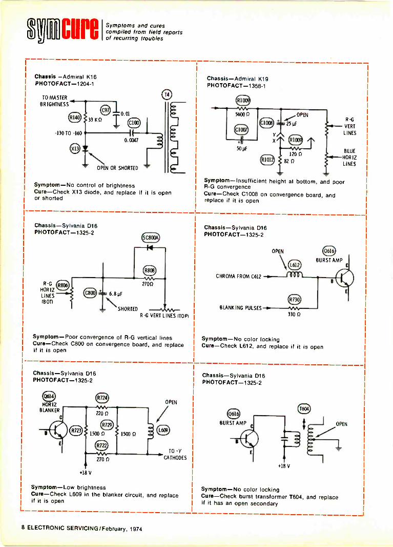
Incurei Symptoms and curescompiled from field reportsof recurring troubles
Chassis -Admiral K16PHOTOFACT-1204-1
TO MASTER
BRIGHTNESS
-130 TO -160
0.0133 K0
0.0047
OPEN OR SHORTED -
Symptom-No control of brightnessCure-Check X13 diode, and replace if it is openor shorted
Chassis-Sylvania D16PHOTOFACT-1325-2
R -G
HORIZLINESai OTI
(c800
R-G VERT LINES (TOP)
Symptom-Poor convergence of R -G vertical linesCure-Check C800 on convergence board, and replaceif it is open
Chassis-Sylvania D16PHOTOFACT-1325-2
HORIZBLANKER
+18 V
Symptom-LowCure-Check L609 in the blanker circuit, and replaceif it is open
270 0
OPEN
TO -Y
CATHODES
brightness
Chassis-Admiral K19PHOTOFACT-1358-1
5600 0
5011
R -G
VERT
LINES
BLUE
HORIZLINES
Symptom-Insufficient height at bottom, and poorR -G convergence
Cure-Check C1008 on convergence board, andreplace if it is open
Chassis-Sylvania D16PHOTOFACT-1325-2
OPEN
CHROMA FROM C612
BLANKING PULSES
330 0
Symptom-No color lockingCure-Check L612, and replace if it is open
Chassis-Sylvania D16PHOTOFACT-1325-2
+18 V
OPEN
Symptom-No color lockingCure-Check burst transformer T604, and replaceif it has an open secondary
L__
8 ELECTRONIC SERVICING/February, 1974
RCM in-depth system forsolid-state servicing.
SK leads the way in solid-stateservicing with its strong in-depthcoverage replacement system.
Now 218 SK devices replaceover 87,000 types, both foreignand domestic, and they are allI sted in the new SK ReplacementGuide, SPG-202P.
SK provides top -of -the -I i nereplacements for the types youare most likely to encounter inday-to-day servicing. For exam-ple, it has in-depth:0 Matched audio pairs 0 Mostpopular IC's 0 RF and VideoTypes 0 TV Deflection Systems
O I F, Chroma, Audio and High -Voltage Types 0 Rectifiers/Diodes.
That's why SK's provide youwith strong in-depth solid-statereplacement coverage for themost popular -selling consumerelectronics equipment:0 TV, Color & BW 0 AudioEquipment 0 H i-F i Systems0 Tape Recorders 0 Radio Re-ceivers 0 Citizens Band Gear.
And there are many morereasons for the growing populari-ty of the SK in-depth coveragesystem. They include RCA's out-
standing top -of -the -line productquality, its full complement ofsolid-state hardware, and its un-matched information supportthat backs the entire system.
Get all the details on SK in-depth coverage system from yourRCA Distributor. Contact himtoday and ask, too, for your copyof the new 1974 RCA SK Re-placerient Guide, SPG-202P.
RCA I Distributor MarketingSomerville, N.J. 08876.
RCASolidState
February, 1974/ELECTRONIC SERVICING 9
troubleshootithSend in your helpful tips-we pay!
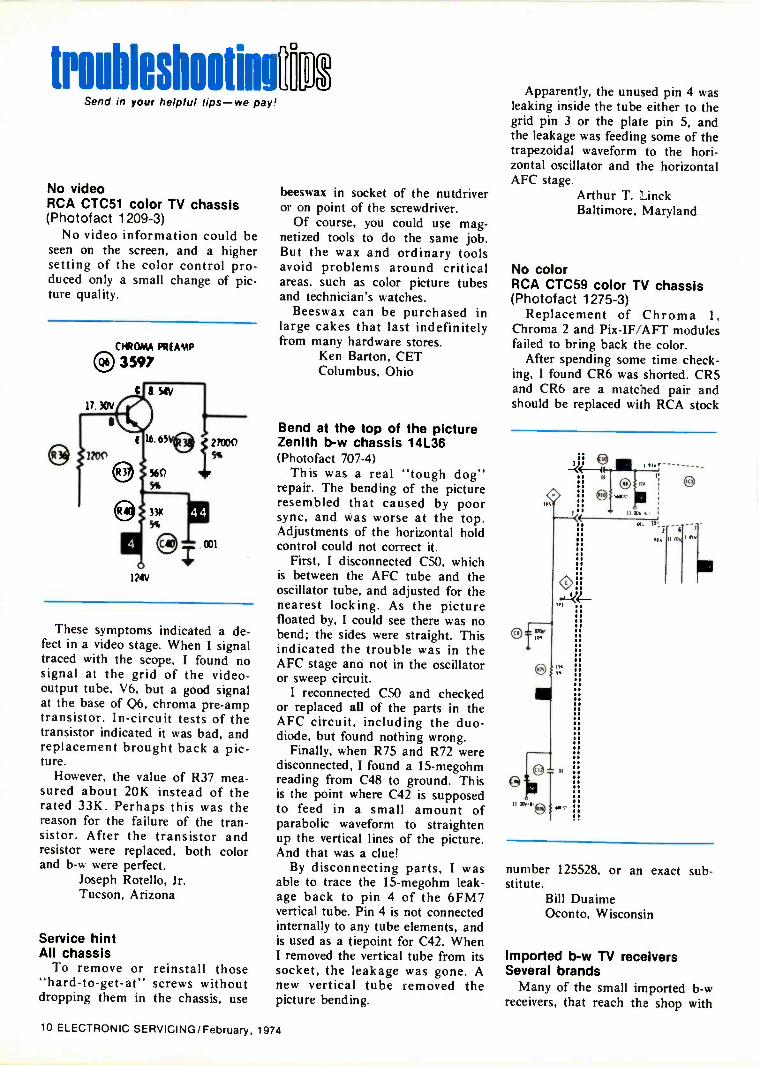
No videoRCA CTC51 color TV chassis(Photofact 1209-3)
No video information could beseen on the screen, and a highersetting of the color control pro-duced only a small change of pic-ture quality.
CHROMA PREAMP0 3597
These symptoms indicated a de-fect in a video stage. When I signaltraced with the scope, I found nosignal at the grid of the video -
output tube, V6, but a good signalat the base of Q6, chroma pre -amptransistor. In -circuit tests of thetransistor indicated it was bad, andreplacement brought back a pic-ture.
However, the value of R37 mea-sured about 20K instead of therated 33K. Perhaps this was thereason for the failure of the tran-sistor. After the transistor andresistor were replaced, both colorand b -w were perfect.
Joseph Rotello, Jr.Tucson, Arizona
Service hintAll chassis
To remove or"hard -to -get -at"dropping them in
reinstall thosescrews withoutthe chassis, use
beeswax in socket of the nutdriveror on point of the screwdriver.
Of course, you could use mag-netized tools to do the same job.But the wax and ordinary toolsavoid problems around criticalareas, such as color picture tubesand technician's watches.
Beeswax can be purchased inlarge cakes that last indefinitelyfrom many hardware stores.
Ken Barton, CETColumbus, Ohio
Bend at the top of the pictureZenith b -w chassis 14L36(Photofact 707-4)
This was a real "tough dog"repair. The bending of the pictureresembled that caused by poorsync, and was worse at the top.Adjustments of the horizontal holdcontrol could not correct it.
First, I disconnected C50, whichis between the AFC tube and theoscillator tube, and adjusted for thenearest locking. As the picturefloated by, I could see there was nobend; the sides were straight. Thisindicated the trouble was in theAFC stage ana not in the oscillatoror sweep circuit.
I reconnected C50 and checkedor replaced all of the parts in theAFC circuit, including the duo -diode, but found nothing wrong.
Finally, when R75 and R72 weredisconnected, I found a 15-megohmreading from C48 to ground. Thisis the point where C42 is supposedto feed in a small amount ofparabolic waveform to straightenup the vertical lines of the picture.And that was a clue!
By disconnecting parts, I wasable to trace the 15-megohm leak-age back to pin 4 of the 6FM7vertical tube. Pin 4 is not connectedinternally to any tube elements, andis used as a tiepoint for C42. WhenI removed the vertical tube from itssocket, the leakage was gone. Anew vertical tube removed thepicture bending.
Apparently, the unused pin 4 wasleaking inside the tube either to thegrid pin 3 or the plate pin 5, andthe leakage was feeding some of thetrapezoidal waveform to the hori-zontal oscillator and the horizontalAFC stage.
Arthur T. LinckBaltimore, Maryland
No colorRCA CTC59 color TV chassis(Photofact 1275-3)
Replacement of Chroma 1,Chroma 2 and Pix-IF/AFT modulesfailed to bring back the color.
After spending some time check-ing. I found CR6 was shorted. CR5and CR6 are a matched pair andshould be replaced with RCA stock
IP!
10.4.
99
a.U.114
S.S.SI
.5It90
BO
Se
9190U.
SO
---------
number 125528, or an exact sub-stitute.
Bill DuaimeOconto, Wisconsin
Imported b -w TV receiversSeveral brands
Many of the small imported b -wreceivers, that reach the shop with
10 ELECTRONIC SERVICING/February, 1974
no high voltage because the hori-zontal oscillator is dead, are foundto have a defective polystyrene -insulated capacitor. Also, in mostcases, these capacitors were physic-ally located very near a hot tube.
We suggest you locate visuallyany such capacitors and checkthem first to prevent wasted time.
Joseph Rotello, Jr.Tucson, Arizona
Cure for bloomingRCA CTC12A chassis(Photofact 640-3)
This chassis showed a bad caseof blooming, defocusing and slightlynarrowing on the left side of theraster, especially when the back-ground was blue, as in newscasts. Itappeared to be classical regulatortrouble, but changing all HV tubesand checking voltages and compo-nents, including the video amp,gave no cure or clue. Later, I
noticed the blue -red Y amp tube(V22) was sparking between ele-ments and I changed the tube. Thetrouble was cured. Possibly, bloom-ing mainly on a blue backgroundshould have been a clue.
R. StanleyPhiladelphia, Pa.
No picture, no soundRCA CTC48 chassis(Photofact 1300-2)
This color set was brought inbecause it would not turn on. Thetriac was jumped as the RCA litera-ture suggested, and an audible humwas evident. Neither picture norraster showed signs of an openfilter; sound was the only clue. Theproblem proved to be an open filtercapacitor in the remote powersupply.
Richard Castanie, CETGrand Rapids, Michigan 0
Got A Troubleshooting Tip?
If you've recently run across anunusual trouble symptom, send athorough description of it and thesolution to:
Troubleshooting Tip,Electronic Servicing1014 Wyandotte St.
Kansas City, Mo. 64105
END OF THEREPLACEMENTTRANSISTORNIGHTMAREjust 47 transistors replaceover 22,500 O.E.M. part numbers.
Finding the right replacement transistor has been a realtoughie for most service technicians. Over 22,500 existing partnumbers have made life difficult. Now, they can be replacedwith just 24 small -signal, 18 power, and 5 field effect tran-sistors. You can get any or all of the 'Fantastic 47' on the self-service Semiconductor Q -Mart at your Sprague distributor's.While you're there, pick up a free copy of the 48 -page K-500Semiconductor Replacement Manual. Or . . . write to SpragueProducts Co., 105 Marshall St., North Adams, Mass. 01247 .
ea ii sinew aril" sr oho Naos or rat op
............................................................................................ . ..........................................................................................
SPRAGUETHE MARK OF RELIABILITY
THE IROAD-LINE PRODUCER OF ELECTRONIC PARTS
For More Details Circle (8) on Reply Ca T
NI -Aachen°Needed: Control unit for C.D.R. Hamrotator.
William Hall, Jr.5095 Sandy Ave. SECanton, Ohio 44707
antenna
Needed: Schematic for a "Knight Laboratory O'Scope"(plug in vertical section). No model number.
H. Stuhler55 Blenheim RoadEnglishtown, New Jersey 07726
Needed: Schematic and manual for an old Supreme385 automatic tube tester.
Justo C. Goitia80 Hato Viejo Buzon 620Arecibo, Puerto Rico 00612
Needed: Schematic for RCA model T62 all -wavereceiver.
Kevin M. Quinn924 Wadsworth St.Syracuse. New York 13208
Needed: One Tannoy 12 -inch dual -concentric speakerwith crossover network. Must be the older 16 -ohmmodel.
T. J. Jones4915 Sierra MadreSan Antonio, Texas 78233
Needed: Addresses for Crystal Corp. and MicrodekCo., makers of radiation testers for micro -wave ovens.
A. J. EdwardsRoyal Oaks Park Space 318145 Soledad CanyonCanyon Country, Calif. 91351
Needed: Viking/Telex model 88 RMQ tape deck forparts. Request price and description of condition.
M. Deflorio, Jr.Suffolf Audio Systems350 Brookville Ave.Islip, New York 11751
Needed: Power transformer, part number P101 -S1 fora Fliteway radio manufactured by Multitech Interna-tional Corp. of Japan.
C. F. Kegley202 N. Bridge St.Bedford, Va. 24523
Needed: Power transformer for 1936 Grunow radio,chassis 12B, 5Z3 rectifier.
Guy's Radio -TVWinfield, Iowa 52659
Needed: Schematic and parts list for the constructionof a theremin.
Joe's Radio and TV65 Plainfield Ave.Shrewsbury, Mass. 01545
Needed: Schematic for Atwater Kent model 84 super-hetrodyne.
Claud Brasher108 W. Main Cross St.Greenville, Ky. 42345
Needed: Schematic for an Ampeg J12 amplifier orlocation of distributor or manufacturer.
M. Ohringer11 MorningsideWestbury, New York 11590
Needed: Schematic and service manual for SuperiorInstruments Co. model 77 VTVM. Will pay reasonableprice.
Paul L. Marcum889 W. Center St.Kingsport, Tennessee 37660
For Sale: Sencore model SS137 Sweep -Circuit Analyzer._fairly new. Make offer or trade for a Heathkit scope.
Barnet Toyen39 Saddle Hill RoadNewington, Conn. 06111
Wanted: Books on TV Tuner Servicing, either "TUN -1Practical TV Tuner Repairs" by Robert Middleton or"STD -1 Servicing TV Tuners" by Jesse Dines, or both.
D. R. SterlingP.O. Box 162Binger, Oklahoma 73009
Wanted: Coils for Heathkit grid-dip meter modelCD -1B. Also Heathkit impedance meter kit modelAM -1.
Walter Schivo560 EldridgeNovato, Calif. 94947
(Continued on page 43)
12 ELECTRONIC SERVICING/February, 1974
We're making it our business to make your business easier.
General Electric's STC program.It takes theirough'out of
'Tough Dog' service.S. stands for our new
Symptom Repair Manual. It wascreated for you by GE to deal withthe most common faults. It lists avariety of symptoms. And then tellsyou what to check and in what order.
T. stands for our Trouble-shooting Flow Charts. If a particular problem was not found byusing the Symptom Repair Manual, these charts will take youthrough a logical sequence of checks to locate the faults.
C. stands for time-consuming Circuit Analysis. Ifthe 'S' and `T,' in most cases you will never have to get to 'C.With these two service aids you can quickly diagnose 95% of allGeneral Electric TV service problems. Using them will save youtime, money and aggravation. And needless to say, they'll helpyou generate a lot of good will and build your reputation for fast,reliable service.
The Symptom RepairManual is available for a $1.00handling charge. To receive yourcopy or details of GE servicesubscription plans, write "Dutch"Meyer, GE Television ReceiverProducts Department, Portsmouth,Va. 23705; or call collect(804) 484-3521. STC. A service technician's
best friend.
GENERAL ELECTRIC
February, 1974/ELECTRONIC SERVICING 13
ELECTRONICS...Medicine's Liveliest HelperBy Joseph J. Carr, CET
Both electronic technology and elec-tronic equipment have been draftedinto the day-by-day practice ofmedicine to such an amazing extentthat many hospitals now employstaff electronic technicians. In somecases (such as at MassachusettsGeneral in Boston. George Wash-ington University Hospital in Wash-ington. D. C.. and the University ofKansas in Kansas City) hospitalshave established large bio-elec-tronics laboratories or medical en-gineering facilities staffed with bothelectronic engineers and assistingtechnicians. We might expect thisin the huge medical complexes, buteven in clinics or smaller hospitals.an impressive array of electronic/
medical equipment is in constantuse by physician/nurse teams tocollect, display. and store vital dataabout the patient's condition.Modern medicine would beseriously crippled without the assis-tance of electronics. This detailedreport is presented to inform thoseq/. you who might intend to servicesuch equipment, and to be interest-ing to the rest of us.
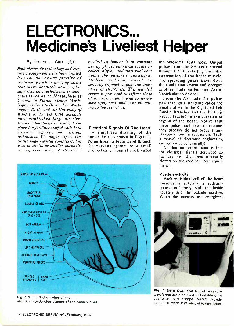
Electrical Signals Of The HeartA simplified drawing of the
human heart is shown in Figure 1.Pulses from the brain travel throughthe nervous system to a smallelectrochemical digital clock called
SUPERIOR VENA CAVA
NERVES
SINOATR IALISA) NODE
BUNDLE Of HIS --
ATRIOVENTRICULARIAVI NOGE
LEFT ATRIUM
RIGHT ATRIUM
RIGHT VENTRICAL
LEFT VENTRICAL
INFERIOR VENA CAVA
PURKINJE FIBERS
BUNDLE I RIGHTBRANCHES I LEFT
Fig. 1 Simplified drawing of theelectrical -conduction system of the human heart.
the SinoAtrial (SA) node. Outputpulses from the SA node spreadthrough the atria starting the initialcontraction of the heart muscle.The spreading pulses travel downthe conduction system and energizeanother node called the Atrio-Ventricular (AV) node.
From the AV node the pulsespass through a structure called theBundle of His to the Right and LeftBundle Branches and the PurkinjeFibers located in the ventricularregion of the heart. Notice thatthese pulses and the contractionsthey produce do not occur simul-taneously, but in succession. Trulya marvel of electronic engineeringcarried out .biochemically!
Another important point is thatthe electrical signals described sofar are not the ones normallyviewed on the medical "test equip-ment".
Muscle electricityEach individual cell of the heart
muscles is actually a sodium -potassium battery, with the insidenegative and the outside positive.When the muscles are energized,
Fig. 2 Both ECG and blood -pressurewaveforms are displayed at bedside on adual -beam oscilloscope. Meters providenumerical readout.(Courtesy of Hewlett-Packard)
14 ELECTRONIC SERVICING/February, 1974
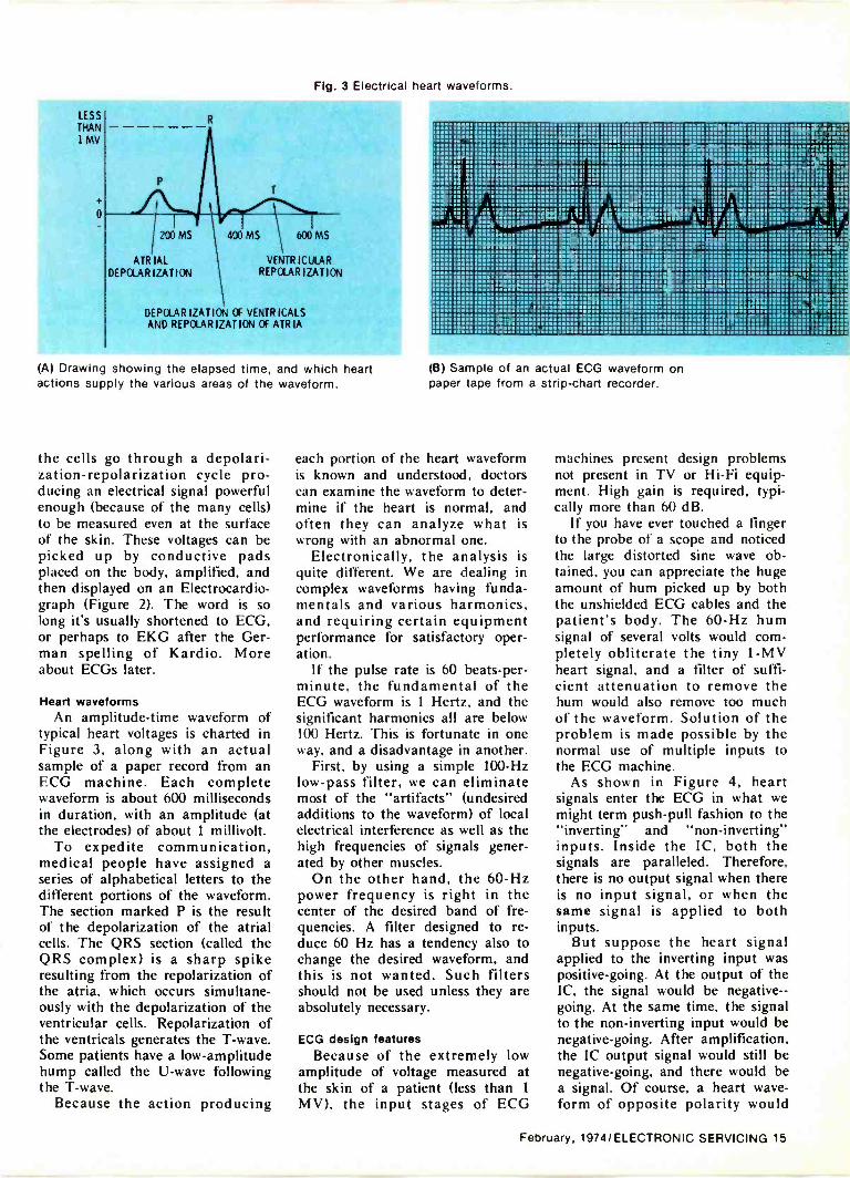
Fig. 3 Electrical heart waveforms.
LESS
THAN1 MV
200 MS 400 MS
ATRIALDEPOLARIZATION
600 MS
VENTRICULARRE POLAR
DEPOLARIZATION OF VENTR ICALSAND REPOLAR IZAT ION OF ATRIA
(A) Drawing showing the elapsed time, and which heartactions supply the various areas of the waveform.
the cells go through a depolari-zation-repolarization cycle pro-ducing an electrical signal powerfulenough (because of the many cells)to be measured even at the surfaceof the skin. These voltages can bepicked up by conductive padsplaced on the body, amplified, andthen displayed on an Electrocardio-graph (Figure 2). The word is solong it's usually shortened to ECG,or perhaps to EKG after the Ger-man spelling of Kardio. Moreabout ECGs later.
Heart waveformsAn amplitude -time waveform of
typical heart voltages is charted inFigure 3, along with an actualsample of a paper record from anECG machine. Each completewaveform is about 600 millisecondsin duration, with an amplitude (atthe electrodes) of about 1 millivolt.
To expedite communication,medical people have assigned aseries of alphabetical letters to thedifferent portions of the waveform.The section marked P is the resultof the depolarization of the atrialcells. The QRS section (called theQRS complex) is a sharp spikeresulting from the repolarization ofthe atria, which occurs simultane-ously with the depolarization of theventricular cells. Repolarization ofthe ventricals generates the T -wave.Some patients have a low -amplitudehump called the U -wave followingthe T -wave.
Because the action producing
(B) Sample of an actual ECG waveform onpaper tape from a strip -chart recorder.
each portion of the heart waveformis known and understood, doctorscan examine the waveform to deter-mine if the heart is normal, andoften they can analyze what iswrong with an abnormal one.
Electronically, the analysis isquite different. We are dealing incomplex waveforms having funda-mentals and various harmonics,and requiring certain equipmentperformance for satisfactory oper-ation.
If the pulse rate is 60 beats -per -minute, the fundamental of theECG waveform is 1 Hertz, and thesignificant harmonics all are below100 Hertz. This is fortunate in oneway, and a disadvantage in another.
First, by using a simple 100 -Hzlow-pass filter, we can eliminatemost of the "artifacts" (undesiredadditions to the waveform) of localelectrical interference as well as thehigh frequencies of signals gener-ated by other muscles.
On the other hand, the 60 -Hzpower frequency is right in thecenter of the desired band of fre-quencies. A filter designed to re-duce 60 Hz has a tendency also tochange the desired waveform, andthis is not wanted. Such filtersshould not be used unless they areabsolutely necessary.
ECG design featuresBecause of the extremely low
amplitude of voltage measured atthe skin of a patient (less than 1
MV), the input stages of ECG
machines present design problemsnot present in TV or Hi-Fi equip-ment. High gain is required, typi-cally more than 60 dB.
If you have ever touched a fingerto the probe of a scope and noticedthe large distorted sine wave ob-tained, you can appreciate the hugeamount of hum picked up by boththe unshielded ECG cables and thepatient's body. The 60 -Hz humsignal of several volts would com-pletely obliterate the tiny 1 -MVheart signal, and a filter of suffi-cient attenuation to remove thehum would also remove too muchof the waveform. Solution of theproblem is made possible by thenormal use of multiple inputs tothe ECG machine.
As shown in Figure 4, heartsignals enter the ECG in what wemight term push-pull fashion to the"inverting" and "non -inverting"inputs. Inside the IC, both thesignals are paralleled. Therefore,there is no output signal when thereis no input signal, or when thesame signal is applied to bothinputs.
But suppose the heart signalapplied to the inverting input waspositive -going. At the output of theIC, the signal would be negative --going. At the same time, the signalto the non -inverting input would benegative -going. After amplification,the IC output signal would still benegative -going, and there would bea signal. Of course, a heart wave-form of opposite polarity would
February, 1974/ELECTRONIC SERVICING 15

E2
BOGY VOLTAGE
(PUSH-PULL INPUTI
INVERTING INPUT
HUM AND NOISE
IPARALLEL INPUT)
OUTPUT
E INT ALA TRIANGLE
RA LA
a
I 111
H
155
;tsa
LL
Fig. 4 Illustration of how hum and noise are cancelled in the Fig. 5 Placement points for the wires of the patient cabledifferential amplifier of the IC, yet the wanted signal receives when taking standard ECG waveforms. The word "leads"full amplification. refers to the voltage drops between these points, such as
the Einthoven Triangle.
A
IL
RA
AR
RA
RA
a
aVL
UNIPOLAR CHEST LEADS
LL
RA
lL
RI. COMMON
oAF
Fig. 6 Different connections of the wires for the "leads" shown.
Fig. 7 Block dia-gram of a heart -rate meter, includ-ing an ECG pre-amplifier.
FLASHER
QRSINDICATOR
SCOPE
CARDIOTACH -soHEART -RATE
INDICATOR
HIGH ALARM
RECORDER
LOW ALARM
ALARM
CIRCUIT
HIGH
.- REMOTE ALARM
GROUNDINGo --
LOW
0 -.10 -RESET ALARM
cause a positive -going output fromthe IC.
Any unwanted signals comingwith the same phase into both in-puts are cancelled by the internalinversion. This is called common -mode rejection, and it is usuallystated in decibels.
Sufficient common -mode re-jection can be obtained only bynear -perfect balance of gain insidethe IC, or a design that includes acontrol for achieving balance. If allelse fails, a 60 -Hz notch filter isswitched in.
ECG inputsA typical ECG system includes
up to five input wires connected toa selector switch, so the voltagedrop across different portions of thebody (cardiologists call them"leads") can be obtained.
Basic connections for the fiveinput wires of the patient cable areshown in Figure 5. The right leg isused as the common point. "Eint-hoven Triangle" connections aremade to the right arm (RA), leftarm (LA) and left leg (LL).
Commonly used ECG "leads" arediagrammed in Figure 6. These arethe unipolar limb leads (designatedI, II, III), the unipolar chest lead,and the augmented limb leads(aVL, aVF and aVR).
Waveforms for a quick look, orfor monitoring for hours, are dis-played on a cathode ray tube, verysimilar to the one in a servicescope. Heart waveforms for perma-nent records are preserved by thetype of ECG that uses either an inkpen or a heated stylus (which writeson special paraffin -based paper) to
16 ELECTRONIC SERVICING/February, 1974
I--- DIASTaT SYSTOLE ---120
Fig. 8 Top view of the Model 7807CHewlett-Packard heart -rate meter. Themeter on front has a long. horizontal,analog scale. Complexity of the circuitis shown by the several plug-in circuitboards.
scribe the waveform onto specialgraph paper that moves throughthe machine.
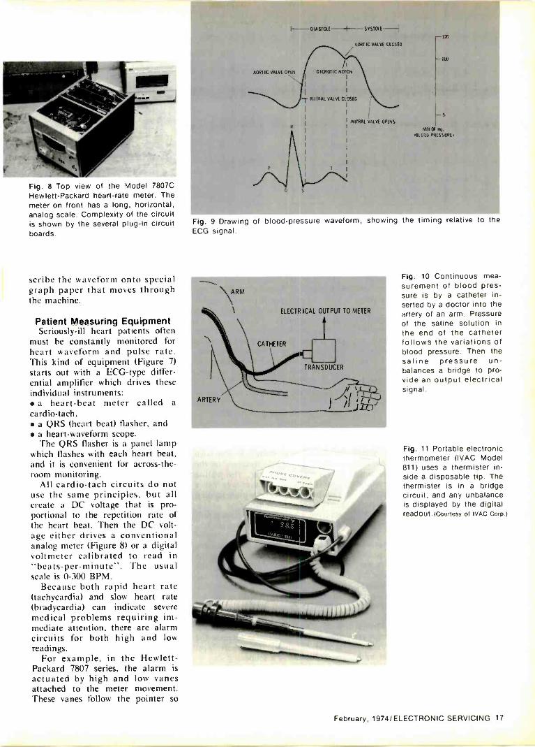
Patient Measuring EquipmentSeriously -ill heart patients often
must be constantly monitored forheart waveform and pulse rate.This kind of equipment (Figure 7)starts out with a ECG -type differ-ential amplifier which drives theseindividual instruments: a heart-beat meter called a
cardio-tack, a QRS (heart beat) flasher, and a heart -waveform scope.
The QRS flasher is a panel lampwhich flashes with each heart beat.and it is convenient for across -the -room monitoring.
All cardio-tach circuits do notuse the same principles, but allcreate a DC voltage that is pro-portional to the repetition rate ofthe heart beat. Then the DC volt-age either drives a conventionalanalog meter (Figure 8) or a digitalvoltmeter calibrated to read in"beats -per -minute". The usualscale is 0-300 BPM.
Because both rapid heart rate(tachycardia) and slow heart rate(bradycardia) can indicate severemedical problems requiring im-mediate attention, there are alarmcircuits for both high and lowreadings.
For example, in the Hewlett-Packard 7807 series, the alarm is
actuated by high and low vanesattached to the meter movement.These vanes follow the pointer so
AORTIC VALVE OPEN
AORTIC VALVE CLOSED
fI
D I CR OT IC NOTCH
MITRAL VALVE CLOSED
MITRAL VALVE OPENS
- 100
-5MM Or Hg.
BLOW PRESSURE)
Fig. 9 Drawing of blood -pressure waveform, showing the timing relative to theECG signal.
\ARM
ELECTRICAL OUTPUT TO METER
TRANSDUCER
Fig. 10 Continuous mea-surement of blood pres-sure is by a catheter in-serted by a doctor into theartery of an arm. Pressureof the saline solution inthe end of the catheterfollows the variations ofblood pressure. Then thesaline pressure un-balances a bridge to pro-vide an output electricalsignal.
Fig. 11 Portable electronicthermometer (IVAC Model811) uses a thermister in-side a disposable tip. Thethermister is in a bridgecircuit, and any unbalanceis displayed by the digitalreadout.(courtesy of IVAC corp )
February, 1974/ELECTRONIC SERVICING 17
HEART -RATE
METER
ECG WIRES ECG
PREAMP
STRIP -CHART
RECORDER
TRANSDUCER
-1=1
TEMPERATURE
METER
TAPE -
CARTRIDGEMEMORY
LOOP
ALARM
BLOOD -
PRESSURE
METER
TWO -
CHANNEL
SCOPE
Fig. 12 Block diagram of a typical patient -monitor system.
they keep a photocell in the darkwhen the heart rate is within thelimits set by a pair of subsidiarypointers on the meter face (thesecan be manually adjusted as de-sired). When the heart rate exceedsthese presets, the photocell isblinded by the vane, causing achange of resistance which cantrigger a SCR used as a switch.
In other cases, the heart rate isindicated by a special left -justifiedtrace on the lower channel of adual -trace scope.
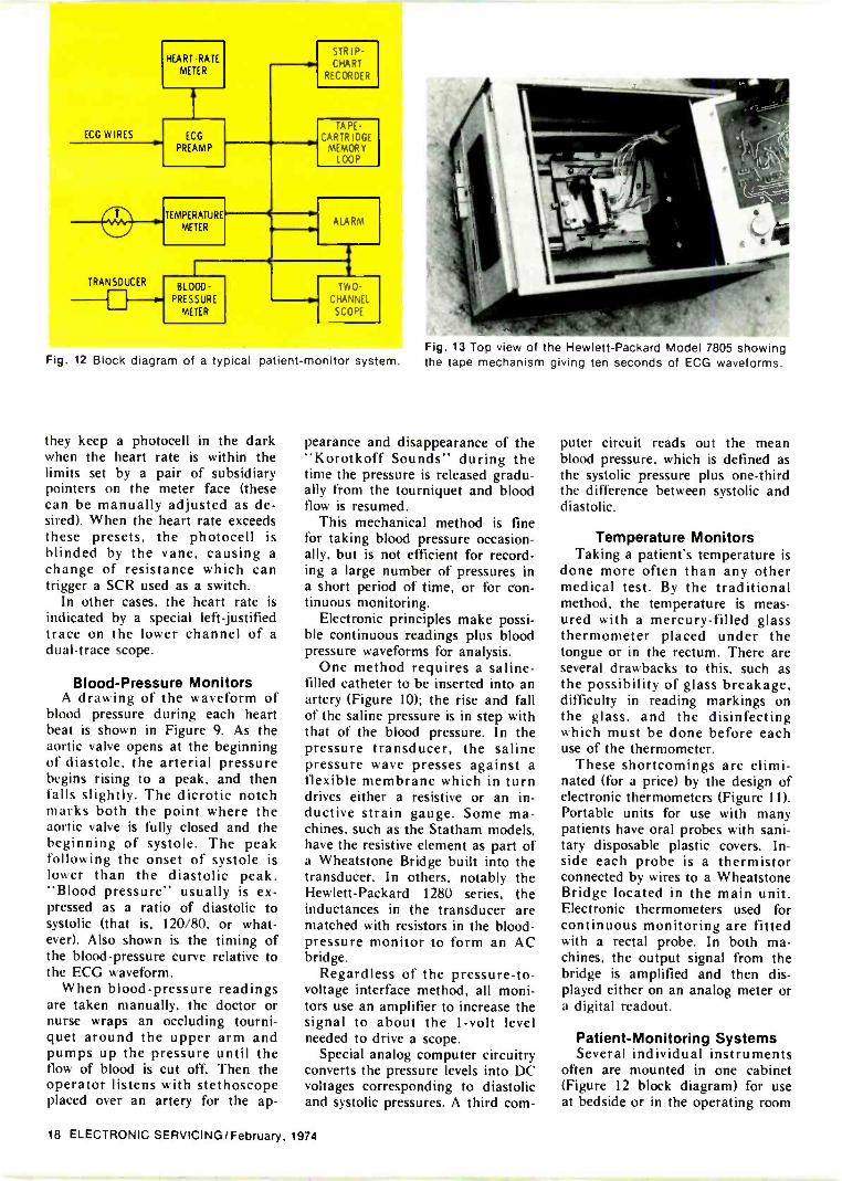
Blood -Pressure MonitorsA drawing of the waveform of
blood pressure during each heartbeat is shown in Figure 9. As theaortic valve opens at the beginningof diastole, the arterial pressurebegins rising to a peak. and thenfalls slightly. The dicrotic notchmarks both the point where theaortic valve is fully closed and thebeginning of systole. The peakfollowing the onset of systole islower than the diastolic peak."Blood pressure" usually is ex-pressed as a ratio of diastolic tosystolic (that is, 120/80, or what-ever). Also shown is the timing ofthe blood -pressure curve relative tothe ECG waveform.
When blood -pressure readingsare taken manually, the doctor ornurse wraps an occluding tourni-quet around the upper arm andpumps up the pressure until theflow of blood is cut off. Then theoperator listens with stethoscopeplaced over an artery for the ap-
Fig. 13 Top view of the Hewlett-Packard Model 7805 showingthe tape mechanism giving ten seconds of ECG waveforms.
pearance and disappearance of the"Korotkoff Sounds" during thetime the pressure is released gradu-ally from the tourniquet and bloodflow is resumed.
This mechanical method is finefor taking blood pressure occasion-ally, but is not efficient for record-ing a large number of pressures ina short period of time, or for con-tinuous monitoring.
Electronic principles make possi-ble continuous readings plus bloodpressure waveforms for analysis.
One method requires a saline -tilled catheter to be inserted into anartery (Figure 10); the rise and fallof the saline pressure is in step withthat of the blood pressure. In thepressure transducer, the salinepressure wave presses against aflexible membrane which in turndrives either a resistive or an in-ductive strain gauge. Some ma-chines, such as the Statham models,have the resistive element as part ofa Wheatstone Bridge built into thetransducer. In others, notably theHewlett-Packard 1280 series, theinductances in the transducer arematched with resistors in the blood -pressure monitor to form an ACbridge.
Regardless of the pressure -to -
voltage interface method, all moni-tors use an amplifier to increase thesignal to about the 1 -volt levelneeded to drive a scope.
Special analog computer circuitryconverts the pressure levels into DCvoltages corresponding to diastolicand systolic pressures. A third com-
puter circuit reads out the meanblood pressure. which is defined asthe systolic pressure plus one-thirdthe difference between systolic anddiastolic.
Temperature MonitorsTaking a patient's temperature is
done more often than any othermedical test. By the traditionalmethod, the temperature is meas-ured with a mercury -filled glassthermometer placed under thetongue or in the rectum. There areseveral drawbacks to this, such asthe possibility of glass breakage,difficulty in reading markings onthe glass, and the disinfectingwhich must be done before eachuse of the thermometer.
These shortcomings are elimi-nated (for a price) by the design ofelectronic thermometers (Figure 11).Portable units for use with manypatients have oral probes with sani-tary disposable plastic covers. In-side each probe is a thermistorconnected by wires to a WheatstoneBridge located in the main unit.Electronic thermometers used forcontinuous monitoring are fittedwith a rectal probe. In both ma-chines. the output signal from thebridge is amplified and then dis-played either on an analog meter ora digital readout.
Patient -Monitoring SystemsSeveral individual instruments
often are mounted in one cabinet(Figure 12 block diagram) for useat bedside or in the operating room
18 ELECTRONIC SERVICING/February, 1974
(OR). Usually the ECG waveformsand the arterial blood pressure aredisplayed on a two -channel scope.
Alternately, four-, six- or eight -channel scopes are available so thatvenous pressure or other ECG leadscan be monitored. Heart rate, therespective blood -pressure levels, andtemperature are read out fromeither analog or digital panelmeters.
Endless -loop tape recorderThe heart activity in the ten
seconds prior to a heart attack is ofgreatest interest to a doctor. Ofcourse, it's possible to operate astrip -chart recorder constantly, butthe expense and trouble of storingall that paper make this impracti-cal. There is an ingenious solutionby the use of a ten -second taperecorder (Figure 13).
In the Constant -Care Unit (CCU)when the onset of a heart attackseems likely, the ECG is wired tofeed an endless -loop tape recorder.This recorder runs continuously,recording the ECG waveforms ontape, and retaining it for ten sec-onds before re-recording. At anygiven time, ten seconds of ECGsignals are on the tape.
Suppose the automatic high orlow heart -rate alarm sounds, indi-cating a heart attack. The tapemachine stops recording and turnson a paper -strip -chart recorder.Now the doctor has all the data he
needs, for the tape machine has thelast ten seconds of ECG signal justprior to the attack, and the paper -strip recorder has the waveformsfollowing the attack.
Other Monitoring Systemsypical of patient -monitoring
systems is the General Electriccentral station shown in Figure 14.
It is the usual practice to have a setof instruments at each bedside andanother set remotely connected atthe central station. In this way thenurses can very effectively monitorat once the condition of severalpatients.
Figure 15 shows a rack -mountedcentral station built by Sanborn(predecessor of Hewlett-PackardMedical Electronics Division) thatis used in the control room of theoperating room suite in a largehospital. At the left is an eight -channel scope, coupled to thegating amplifier (below the scope)which acts as an electronic switchto time the scope presentation. Thescope phosphor is a blue long -persistence P-7 type.
In the middle rack are mostlysignal conditioners and preampli-fiers tied to the input lines from thevarious operating rooms. At the topof the center rack is a multiplereadout device that displays heartrate, blood pressures, etc. in nu-merical form.
Almost out of the picture on the
1 _
r E1 I r= ]A- -
Fig. 14 This General Electricnurse to monitor the condition(Courtesy of General Electric Co.)
remote console allows oneof several patients.
right is a fourteen -track instrumen-tation tape recorder using one -inchtape. This machine converts thelow -frequency ECG waveforms orblood -pressure waveforms to ahigher audio frequency (usually thewaveform frequency modulates anaudio carrier) for recording ontothe tape.
This system allows the monitor-ing and recording of ECG, EEG(brain waves), and pressures frompatients in several operating roomsand in the Post Anesthesia Re-covery Room (PARR). Day-to-dayoperation of the instruments andthe collection of data records arefunctions of an instrumentationnurse and a staff of several monitortechnicians. An electronics tech-nician is responsible for mainte-nance of the instruments, and it isnecessary that he work closely withthe medical people who use thesystem daily.
ET's In A Hospital EnvironmentAs you might imagine, an elec-
tronic technician repairing equip-ment in a hospital is in a strange,different world.
For example, if a breakdownoccurs in the OR, you will have todress in the appropriate green orblue surgical garb (scrub suits) be-fore entering. In fact, you will comeinto contact with any number oflittle rules, for which you won't see
(Continued on page 56)
Fig. 15 Control -room instrumentation in the operatingcomplex of George Washington University Hospital canmonitor up to eight parameters, or the same parameter ofeight different patients.
February, 1974/ELECTRONIC SERVICING 19
QUANTUM AMPLIFIER
Oneeasy
solutionto five
difficultreceptioproblemi-N
UHF ADJUSTABLE BAND SPAN
QUANTUM FM TRAP MOUNT 300 or 75 OHM
It's the Channel Master QuantumSystem the total system that's engineeredfrom stem to stern to handle the problems that makepeak reception more difficult each day. The QuantumAntenna and accessories provide the one-step solutionto TV and FM reception problems such as:
lNOISE POLLUTION: The electromagneticnoise and interference from power lines, ig-nition switches, electrical appliances, co, andadjacent channel interaction and hospitalequipment. The Quantum Antenna cutsthrough the noise with the highest front toback ratios and directivity yet engineered intoantennas, to reach desired channels with a
ew standard of clarity and sharpness!1000. 410*- 4111111%6-IWEAK SIGNALS: The Quantum's optional
amplifier modules*provide up to a 15dBboost for color and black and white receptionin fringe areas! The solid state modules pro-vide high gain, low noise and unconditionallystable operation through a wide temperaturerange, and include switchable FM traps. Theamplifiers fit snugly into the Quantum's
`weather protected terminal housing.
FM INTERFERENCE: A growing problem with the FM boom. Quantum optional FM
traps provide up to 25dB effective attenua-tion across the entire band without affectingthe powerful front to back performance inany way. The printed circuit board traps areeasy to install in the terminal housing.
A WEAK UHF PERFORMANCE: The Quantum provides exceptional UHF power with an ad-
justable band span that permits you to mar-ket an antenna tuned to current and futureUHF channels in your area. Gain as high as13dB meets the critical demands of UHFcolor reception!
IMPEDANCE MATCHING: The Quantum provides an excellent match to both 300 and
75 ohm impedances! It uses insulation pierc-ing terminals for 300 ohm hookup, and aoptional balun/matching transformer for 75
i_ ohm installation. The balun/matching trans-. former fits into the terminal housing.
PLUSMASSIVE, ALL WEATHER POWER! TheQuantum has an extra rugged, double trussconstruction, wind tunnel tested to with-stand better -than -hurricane force winds.The weather protected terminal housing onthe massive twin boom provides a safe har-bor for the Quantum's optional accessorycomponents.
CHANNEL MASTER QUANTUMOne solution to every problem you're likely tomeet ---the Quantum Total Reception System!
For More Details Circle (11; on Reply Card*Optional Amplifier Modules for use with Quantum models 1110, 1111, 1112, 1113, 1160, 1161, 1162.

Shortcuts forservicing AGC in RCA portables
By Lawrence Bowen
There are two general approachesto servicing solid-state AGC sys-tems: DC voltage analysis and sub-stitution of AGC bias. Both areexplained relative to RCA portablecolor receivers.
Beginning with the CTC42 chas-sis, RCA has marketed a family ofsimilar chassis for their hybrid por-table color receivers. First intro-duced in 1969 and 1970 were theCTC41, CTC42 and CTC43. Fol-lowing these came the CTC51,CTC52, CTC53 and CTC55, withprincipal differences only in thehorizontal -deflection and high -volt-age systems.
Earlier chassis used a solid-statedamper diode and a pulse HVregulator, but the later ones shiftedto a vacuum -tube damper and grid -voltage regulation of the horizontal -output tube. Next in the seriescame the CTC63 and CTC66, witha solid-state tripler that replacedthe vacuum -tube high -voltage recti-fier.
Also, there have been other dif-ferences, such as the addition ofvertical -retrace blankers, high -voltage protection circuits, Accu-Matic, etc; but the IF amplifiers,video stages. tuners, and the AGCsystems are very similar throughoutthe line. In effect, when you under-stand one chassis, you know themall.
Basic AGC SystemPractically all modern television
receivers,use keyed AGC to main-tain a constant output from thevideo detector. There are two majoradvantages in using keyed AGC.First, the amount of gain reductiondepends on the amplitude of thehorizontal sync pulses, not on thevideo level which can change drasti-cally with picture content. Also, thecircuit is nearly noise -immune be-cause the amplitude of signal is
sampled only during the horizontalretrace time. Noise signals receivedat other times can be seen in thepicture, but they cannot affect thelocking.
Tube -type keyers
An older AGC circuit using atube keyer is shown in Figure 1.The basic circuit action is describedmost accurately as a grid -controlledrectifier, and the explanation isclearer when taken in steps.
First, imagine the grid connectedto the cathode to give zero bias.Pulses at the plate are rectified toproduce a negative voltage. It'sinteresting how positive -goingpulses can manufacture a negativevoltage. Assume a pulse amplitudefrom the flyback of +150 volts, andthat VI conducts enough to makethe plate -to -ground voltage +50volts. That means 100 volts is drop-ped across Cl, with the flyback sidepositive and the tube side negative.Next, the no -voltage space betweenpulses arrives, and the tube stopsconducting (becomes an open cir-cuit). But Cl still has a 100 -volt
charge across it. To DC, Cl isgrounded through the winding ofthe flyback; therefore, the end ofCl at the plate measures a negative100 volts. This is generally trueeven when the tube is replaced by adiode or a transistor junction.Polarity of the DC voltage is deter-mined by polarity of the diode, notby waveform of the input signal(although the amount of DC changesaccording to the waveshape).
If the grid of VI is made nega-tive relative to its cathode, the plateresistance is increased. This de-creases the efficiency of the rectifi-cation, and results in a lower nega-tive voltage reading. In practicalcircuits, positive -going video is ap-plied to the grid, and a fixedpositive DC voltage clamps thecathode voltage. Bias during hori-zontal retrace time is the differencein voltage between the horizontalsync tips and the DC cathode volt-age. An AGC control usually isprovided to adjust this voltage sothat the desired video signal isobtained.
A stronger station signal de -
0POSITIVE -GOING Ct
AGC KEYING 0
HORIZ PULSES -P-1
POSITIVE -GOINGCOMPOSITE
VIDEO
B+
C2RS
Ro
AGC TO
IF TUBE
AGC TO
RF TUBE
Fig. 1 Basic AGC keyer stage using a tube. Bias changes the plate resistance,and the plate resistance determines the amount of rectified negative voltage.
22 ELECTRONIC SERVICING/February, 1974

creases the bias of the keyer tube,increases the negative voltage at theplate. decreases the gain of the IFand tuner tubes, and produces aweaker video signal. This sequenceis reversed when the station signalbecomes less strong.
AGC voltages for the RF and IFtubes are filtered to remove thehorizontal pulses, but they do notrequire amplification because tubesdo not draw grid current on nega-tive voltages.
To minimize snow on medium -strength station signals, B+ isbrought in through R6 to cancelthe negative AGC voltage to the RFstage until the signal strength ex-ceeds the design threshold. Moreabout this important voltage delaylater.
Transistor/diode MoyersTransistorized AGC keyers
(Figure 2) work about the same asthose with tubes, with two excep-tions. Transistors come in twopolarities, so positive -going pulsesare used with NPN, and negative -going pulses are applied to PNPtransistors. The latter conditionproduces a positive DC voltage.
The other difference is the addi-tion of the diode, CR1. Let's consi-der what would happen if we re-
placed CR1 with a piece of wire.The positive -going pulses wouldprovide a voltage drop across Cl,because the transistor has the cor-rect polarity for collector -to -emittercurrent flow (assuming base/emitterforward bias). A negative voltagewould be formed at the collectorafter each pulse has passed, exceptit is the polarity to flow through thecollector/base junction. In otherwords, the diode current of transis-tors shorts out the desired negativevoltage. A transistor cannot be usedin the tube circuit without a diodeto block the leakage.
In transistorized versions of AGCkeyers, the tube functions aredivided into diode action (CR1diode) and series variable resistance(QI transistor). Sometimes a resis-tor is added to limit the peakcurrent.
Complete AGC-Keyer CircuitFigure 3 shows the AGC-keyer
circuit of the RCA CTC66 chassis.Direct coupling is used all the wayfrom the video detector to the AGCkeyer. The second -video amplifier isshown since a brief explanation ofits operation is in order.
The first video amplifier is anemitter follower which drives thesecond video amplifier and also the
CtPOSITIVE -GOINGHORIZ PULSES .-11
POSITIVE -GOINGCOMPOSITE P'VIDEO
B+
eI
AGC TO IFTRANSISTOR
AGC TO RF
TRANSISTOR
Fig. 2 When a transistor is substituted for a tube in the keyer circuit, a diode inseries with the collector is necessary to prevent the negative rectified voltagefrom leaking away through the collector -to -base circuit.
chroma system. Sync pulses arepositive -going from the video detec-tor, and the polarity is the sameinto the second video amplifier.Both the emitter and the collectorof the second video amplifier areloaded. Output from the collectordrives the video delay line. Emitteroutput drives the AGC keyer andthe sync separator.
L108 and C120 are series re-sonant at 3.58 MHz to trap chromaout of the luminance video. C241returns this trap to ground and alsoacts as a low-pass filter for thevideo that is directed to the AGCand sync separator. There is nonecessity to have wide -band videofor them, and C241 will bypass toground any noise spikes whichmight be riding on top of the syncpulses.
Operation of the keyer itself wasexplained before, except for thefunction of C508. It and C505 forma capacitive voltage divider to re-duce the amplitude of the flybackpulse of the CTC66 to what it wasin earlier chassis of this family.This type of pulse -voltage divisionis frequently used when a manufac-turer adapts an existing AGC cir-cuit to a new chassis.
Tuner AOCThe AGC keyer has two outputs,
one for the tuner and one for theIF amplifiers. Consider the tunerAGC system first. R504 and C503filter the AGC voltage. C4003 islocated on the tuner assemblywhere it is used to filter out anyhum which might be picked up inthe cable harness. Hum in the AGCwill produce hum in the video. C17is a teed -through capacitor throughthe tuner shield.
R4001, R4003, and 84005 deter-mine the AGC delay and its effecton receiver noise. A good signal-to-noise ratio is needed to minimizesnow when the signal from theantenna is below about 500 micro-volts, and this ratio is obtainedwhen the RF stage operates atmaximum gain. Therefore, theAGC bias should not begin todecrease the RF amplifier gainuntil this minimum signal level is
February, 1974/ELECTRONIC SERVICING 23

2ND VIDEO
POSITIVE -GOING
VIDEO FROM
1ST VIDEO AMP
2 TO 2.5 V P -PPOSITIVE -GOING ---
VIDEO
18 VOLTS
REGULATED
(R243) 270 0
FO
SYNC
SEP
0.01
=7-
R?41:,
0 0018C 504
1
568) C(R
C505 330 pF
10 VIDEODELAY LINE
C5081 56 pF
101(ct
0501 E(R502AGC KEYER
16.5 V
1000 T?
560 0
El 17.3 V
Fig. 3 Schematic of the AGC keyer and second videostages used in the RCA CTC66 :hassis
0.01
10 MT)
1.2 MT?
RF
SIGNAL
0.01
R255
100K
0.01
12 MO
R11.
170 V
HORIZ
PULSES
TO
AGC AMP
280 V
TO GRID Of
RF AMP
IF
INPUT
130 V
IF
AGC INPUT10041 RF BIAS \
2.5 MO
CONNECT BIAS
POT HERE
10 pF
1800
c
AGC AMP
2ND F
1000 0
1ST IF
130 V
ADJUST BIAS
POT FOR 38 V
HERE BEFORE
MEASURINGOTHER VOLTAGES
3600 0
0.001
Fig. 4 The first and second IF transistors are in series to DC in the RCACTC66 chassis. Emitter current of 0201 also flows through R206 tocontrol the IF gain.
exceeded. AGC voltage at the keyerbegins to be developed at a muchlower signal level, but R4001,R4003, and R4005 "hold oft- this
a sizable signal is re-ceived.
When there is no station tunedin. and thus no negative voltagecoming from the keyer, it appearsthe grid of the RF tube would besupplied with about +30 volts,enough to damage the tube. How-ever, the grid/cathode part of thetube acts as a diode to bleed itdown to about +2 volts. About 50volts is dropped across R4001 andthe balance of the 280 -supply voltsis developed across R4005. TheAGC keyer must develop -50 voltsto overcome the +50 volts at thejunction of R4001 and R4005 be-fore the gain of the RF amplifiercan be reduced. This should be atabout 500 microvolts of signal, al-though setting of the RF Bias con-trol determines the actual level atwhich gain reduction occurs. This iswhy a wrong adjustment of the RFBias control can cause snow in thepicture, even though the control isactually in the IF circuit. Theseparate AGC paths to RF and IFare nearly independent of eachother. If one is kept from operat-ing, the other tries even harder. So,when the IF's receive less gain*eduction, the RF stage receives
24 ELECTRONIC SERVICING/February, 1974
more. The reduced RF gain makesthe mixer gain more prominent,thus increasing the snow.
The switch which connects R4003into the circuit is closed only whenthe VHF tuner is set to the UHFposition. Its effect is to increase theno -signal positive bias of the RFamplifier tube. Therefore, a higherlevel of UHF signal is necessary toreduce the gain of the RF stage inthe VHF tuner.
IF AGCAGC voltage for the IF transis-
tors does not come directly fromthe keyer (see Figure 4), but a partof the keyer voltage is filtered andused to change the bias of 0201.R255, 8211 and R212 furnish a DCoffset between the negative keyeroutput and the positive voltage re-quired to bias the base of Q201.Emitter current of 0201 changesthe biases and currents of Q202and 0203 to vary their gain.
IF transistors Q202 and Q203normally are biased to producemaximum gain when there is nostation signal. Both are in series sothey have essentially the same cur-rent. Any increase of the currentabove the amount giving maximumgain decreases their gain.
0202 and Q203 are supplied withfixed base voltages by the bleedernetwork R214, R215, 8203, R207and RT201 connected from B+ toground. (RT201 is a thermisteradded to keep constant the gain ofthe IF transistors as the tempera-ture varies.) Therefore, the biases of0202 and 0203 are controlled bychanging their emitter voltages.
In normal operation, the voltageacross (and the current through)R206 emitter resistor is stabilized towithin a fraction of one volt. Itmust be this way, because the basevoltages are clamped, and thevariation of the emitter voltage re-presents nearly the total AGC volt-age for the IF transistors. Typically,the voltage change is about .1 volt.
It appears at first glance thatonly the bias voltage of Q202 ischanged by the AGC, so let's di-gress a moment. As the bias of0202 is varied, its collector/emitterresistance changes. And this same
collector/emitter junction is theemitter load for 0203. For example,when the voltage at R206 is re-duced, Q202 has more forwardbias, draws more current and be-comes a lower resistance betweencollector and emitter. This reducesthe emitter -to -ground voltage ofQ203, giving it increased forwardbias and more current flow. There-fore, the AGC actually is applied toboth IF transistors.
Normally, when there is no sta-tion signal, R206 carries the maxi-mum current of Q201 and theminimum current of 0202/0203.As the base of Q201 is driven lesspositive (by a stronger stationsignal, or adjustment of the RFbias control), its current decreases,thus increasing the current of0202/0203 and decreasing theirgain. These facts should always bekept in mind when you trouble-shoot this circuit.
RF-bias controlThe of snow to ad-
justments of the RF-bias control.821 1, already has been discussed,along with comments about thepeculiarity of a control in the IFcircuit that changes the RF gain.Equally important is the overloadof the mixer stage in the tuner thatcan occur if the control is turnedtoo far in the other direction.
In most cases, you should adjustRF-bias control (211) until snow isseen in the picture, then reverserotation until the snow barely iseliminated. No more than that. Ifthere's no snow noticed on onechannel, try another. Do not adjustthe control again unless you noticea tendency towards overload onstronger channels.
Troubleshooting AGCSuspect the AGC system if the
symptoms are: a snowy picture, cross -talk between channels(windshield wiper), no (or weak) video, or excessive video (overloaded orblack raster).
The first two symptoms can becaused by wrong adjustment of theRF-Gain control, so this should be
the first thing checked.Only two tubes, the RF amplifier
and the video -output amplifier, areused in the entire video chain. Tokeep from wasting time, test thesetubes first before you proceed.
Next, use a reliable in -circuittransistor tester to check the IF,AGC keyer, AGC amplifier/inven-ter, and video transistors. This is abig time saver, even though a badtransistor might occasionally slip bythe test.
DC -voltage testsDon't waste a lot of time and
effort measuring DC voltages in theRF. IF, video and AGC stages. Ifthe AGC system is at fault, most ofthese voltages will be abnormal,anyway.
Voltages in the 0202/0203 cir-cuits change such a small amountas to be unnoticeable under mostnormal AGC conditions. Only whenthe emitter voltage of Q202 is outof tolerance should voltages therebe of concern.
Blas dampersObtaining normal, maximum -
gain AGC bias for the RF tube iseasy; just ground the AGC at thetuner. In Figure 3, this is thejunction of 8504 and R4001. Physi-cally, it is where the green wireconnects to the tuner.
If the maximum RF gain obtain-ed by grounding this point causes
1)0 V
IMO)111
1w
TO WIPER OF R211
20 KC/ (BASE Cf 0201i
Fig. 5 Build this bias damper to aidin testing the AGC action in RCAhybrid portable color receivers.
February, 1974/ELECTRONIC SERVICING 25
overload on strong station signals,remove one or both of the antennaleads to weaken the signal.
Clamping the bias of the IFamplifiers is slightly more difficult,but not much. Obtain a 20-Kpotentiometer and a 18-K 1 -wattresistor and wire them as shown inFigure 5. 8209 is easy to find; it'sthe large blue 1800 -ohm 3 -wattresistor at the top/left corner of theIF board. The upper end of itconnects to the ±130 -volt supply.
After this clamper is connectedto the wiper of the RF Bias control(base of Q201), adjust the pot in aneffort to obtain a normal picture. Ifyou get one, leave the clamperconnected and troubleshoot theAGC keyer circuit. At the end ofR507 away from Q501, you shouldmeasure about 2 to 2.5 volts ofpositive -going video. Amplitude ofthe flyback pulse at the junction ofC505 and R505 should be 150 volts,positive -going. Be sure to checkCR502. Leakage or a short allowsthe negative voltage to leak awaythrough the collector/base junctionof Q501, thus giving weak AGCaction. An open in CR502 elimi-nates any path for the pulses toreach the keyer transistor, andtakes away all AGC.
If adjustment of the damper potdoes not bring in a picture, connecta scope to the base of the first -video amplifier (0205, not shown inthe schematic), and adjust thedamper pot for a 2 -volt p -p posi-tive -going video signal. Normalvideo at this point tells us that theproblem is in the video amplifiersthat follow.
Lack of video there might becaused by a defective video -detectordiode. It's under a shield, but wecan check it indirectly. Connect thescope to terminal 3 of the soundmodule. Adjust the clamper potagain, and if you find about 2 voltsof video during the adjustment,chances are good the video detectoris faulty. No video there indicates adefect in the tuner or IF section.
Check the tuner output signal byusing a scope with a detector probeconnected to the variable -couplingcapacitor that couples the tuneroutput to the first -IF amplifier.
This is C204, and it is located nearthe top of the IF -amplifier board.How much amplitude you can ob-serve depends on the detector probeand the strength of the station. Ithelps to measure this signal in areceiver that is working okay, thenwrite the figure on the wall forfuture use. Most tuners will pro-duce about the same reading.
Of course, if your shop boastsone of the new "tuner subbers",you could reverse the procedureand inject the tuner signal at the IFinput. However, it's still necessaryto bias the IF amplifiers properly tolocalize the problem to the AGCsystem or the IF/video circuitry.
If the tuner has normal output,use the probe and scope to follow itstage -by -stage through the IF's. Be-cause the amplitude of signal de-pends on the amount of bias -clamping voltage, you should adjustthe clamper pot as necessary toobtain signals from the first andsecond IF stages.
Whenever the defect is either ashorted or open component,signal -tracing technique will local-ize the trouble. However, it mightnot if a resistor in the biasingnetwork for Q202 and Q203 is awayoff tolerance. The voltages shown inFigure 4 are normal for no -signaloperation, but only if the emittervoltage of Q202 is correct. Don'tconnect any kind of bias damperdirectly to this emitter! Instead,connect it as shown to the base ofQ201 (or if that transistor is bad, tothe emitter of Q201).
Conclusions ,
Two things add to the difficultiesmany technicians seem to have inservicing AGC problems. One is alack of understanding of how thecircuits work (a need we hope hasbeen filled here). The second isattempting to find the trouble with-out first setting up controlled con-ditions for testing. A logical step-by-step procedure will save youmany hours of troubleshooting timefor all but the simplest problems.
The testing procedure is sum-marized as follows: Check tubes and transistors, ground the tuner bias and clampthe IF bias, and
adjust clamped IF bias to obtaina picture. If a picture is obtained, the AGCkeying system is at fault.
(A) Check video and pulse inputsto keyer.
(B) Check voltages and resis-tances in keyer stage. If no picture is obtained, thetuner, IF's or video stages are bad.
(A) Scope the base of first -videoamplifier, and adjust clamper for 2volts of video.
(B) Signal trace the video to AGCkeyer, and to picture tube. If there is no 2 -volt p -p videosignal from the video detector,check for video from the sounddetector (adjust damper as neces-sary). Video there proves videodetector is bad. No video indicatesloss of signal in tuber or IF's. Check tuner output with detectorprobe and scope at input of thefirst IF. If insufficient, repair orreplace tuner. Signal trace the IF stages whileadjusting clamping voltage. With theto the base of 0201, adjust it for 38volts at the emitter of Q202. Thenmeasure voltages in the 0202 andQ203 stages. After trouble is cleared, adjustthe RF Bias (noise control) forminimum snow on meiium-to-weaksignals, but without overload onstrong signals.
Although you probably can findmost AGC troubles in these RCAmodels by slavishly following thisprocedure, it's much better to knowthe theories behind the circuits andthe tests. Then you can tailor theanalysis for even better speed, andalso extend the tests to otherbrands and models of TV receivers.
El
ELECTRONIC SERVICING
is your magazine!
If you would like to see anarticle about a particular sub-ject directly related to servic-ing consumer or communica-tions electronic products, sendus your suggestion.
26 ELECTRONIC SERVICING/February, 1974

The Single Source For Reliable Protection For EveryType Of Electronic And Electrical Circuit And Devici
Include dual -element "slow -blowing" fuses, single -element "quick -acting"fuses and signal or visual Indicating type fuses . . . in sizes from 1/500amp. up ... PLUS: a companion line of fuseholders.
HMR - RF shieldedfuseholder for1/4 x 11/4 In. fuses
HKPpanel
mountedfuseholder
for 1/4 x 11/4 infuse.
BUSS SNAPLOCK FUSEHOLDER - Rear panel -mounted fuseholder for1'4 x 114" fuses. Snaps in-to place. Specify HTA-00for space -saver type.HLD-00 for visual -indicat-ing type, HKP-00 forstandard fuseholder. orHJM-00 for I/4 x i" fuses.
./* HKAlamp -
indicating,signal -activating
fuseholder.
SUBMINIATURE FUSE-Ideal for space tight appli-cations. light weight, vibration and shock resistant.For use as part of miniaturized integrated circuit,larpe multi -circuit electronic systems. computers,printed circuit boards, all electronic circuitry.
IRON Sub -Miniature PigtailFuses - Body size only.145 x .300 inches. Glasstube construction permitsvisual inspection of ele-ment. Hermetically sealed.Twenty-three ampere sizesfrom 1/100 thru 15.
BUSSSubMiniatureGMW Fuseand HWA Fuse -holder. Fuse sizeonly .270 x .250inches. Fuse haswindow for visualinspection of element.Fuse may be used withor without holder.1/200 to 5 amp. Fusesand holders meetMilitary Specifications
BLOCKS FOR BUSS FUSESAll types available f )revery application. Singlepole, multiple pole, smallbase, full base, moldedbase, laminated base, pc r-celain base for fuses frcrn1/4 x 5,8 inches up. Alsosignal fuse blocks adspecial blocks of all types.
SMALL DIMENSION FUSES
AND FUSEHOLDERS
IRON P Rectifier Fuses For the SafeProtection of Solid State DevicesProvide extremely fast opening on overloadand fault currents, with a high degreeof restriction of let-thru current. Many typesand sizes available. Ampere ratings fromvz to 1000 in voltages up to 1500.
TIE COMPLETE LINE OF SIGNAL -INDICATINGALARM -ACTIVATING FUSES
For use on :omputers, microwave units, communicationment, all electronic circuitry.
(.1- BUSS GLDV 4 x 11/4 in.Visual -Indicating,Alarm -Activating.
BUSS GBA1/4 x 1'/4 in.VIsual-Inclicatin I
BUSS MIC13/32 x 11/2 in.
Alarm-Activatirp.
BUSS MIN13/32 x 11/2 in.Visual -Indicating.
FNA FUSETRONiKs dual -elementFuse13/32 a 11/2 in. slow -blowing, Visual Indicating. Alarm -Activating. (Also useful forprotection of sn all motors, sole-noids, transforn ers in machinetool industry.)
BUSS GrasshopperFuse. Visual -Indicating,Alarm -Activating.
equip -
BUSS ACH AircraftLimiter. Visual -Indicating.
BUSS GMT and HLT holder. Visual -Indicating, Alarm -Activating.
FOR AJORE INFORMATION ON THE COMPLETE BUSS LINE,WRITE FOR BUSS FORM SFB.
BUSSMANN MANUFACTURINGa McGraw -Edison Company DivisionSt. Louis, Missouri 63107 BUSS. FUSES
i HE QUALITY LINE
February, 1974/ELECTRONIC SERVICING 27
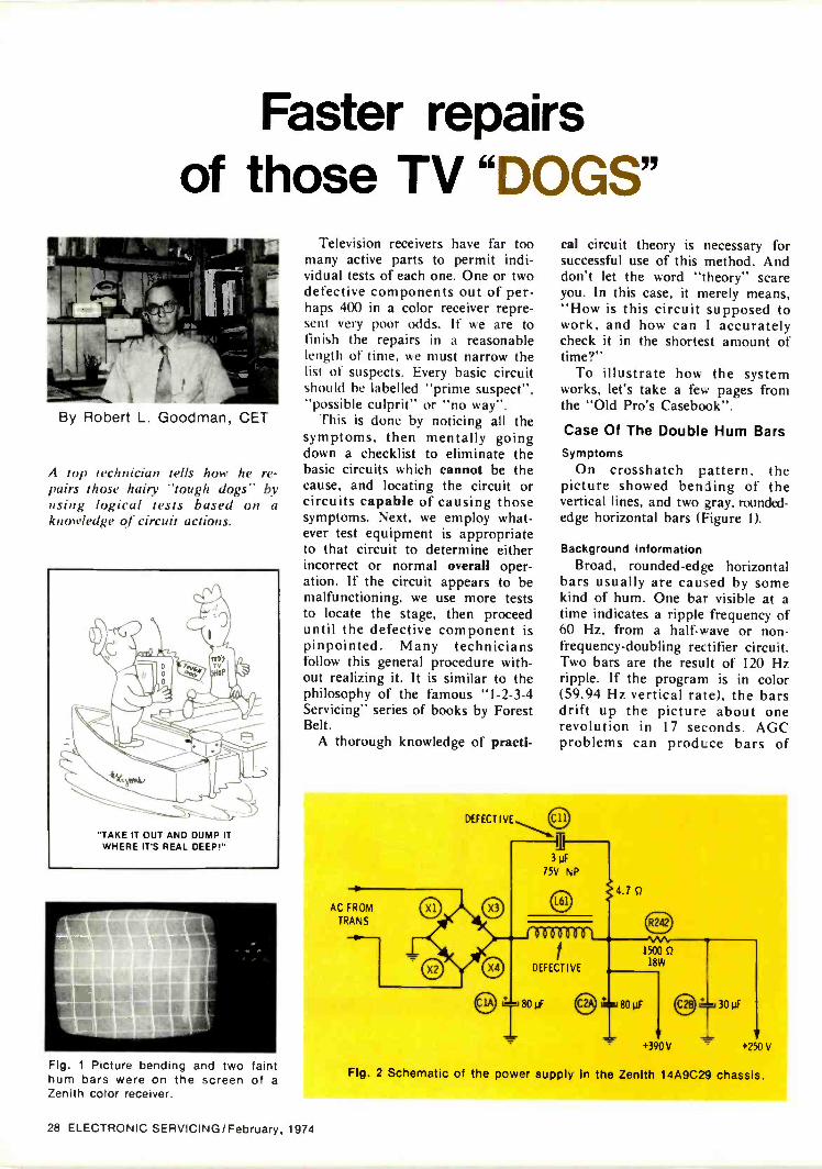
Faster repairsof those TV "DOGS"
By Robert L. Goodman, CET
A top technician tells how he re-pairs those hairy "tough dogs" byusing logical tests based on aknow/edge of circuit actions.
"TAKE IT OUT AND DUMP ITWHERE IT'S REAL DEEP!"
Fig. 1 Picture bending and two fainthum bars were on the screen of aZenith color receiver.
Television receivers have far toomany active parts to permit indi-vidual tests of each one. One or twodefective components out of per-haps 400 in a color receiver repre-sent very poor odds. If we are tofinish the repairs in a reasonablelength of time, we must narrow thelist of suspects. Every basic circuitshould be labelled "prime suspect","possible culprit" or "no way".
This is done by noticing all thesymptoms, then mentally goingdown a checklist to eliminate thebasic circuits which cannot be thecause, and locating the circuit orcircuits capable of causing thosesymptoms. Next, we employ what-ever test equipment is appropriateto that circuit to determine eitherincorrect or normal overall oper-ation. If the circuit appears to bemalfunctioning, we use more teststo locate the stage, then proceeduntil the defective component ispinpointed. Many techniciansfollow this general procedure with-out realizing it. It is similar to thephilosophy of the famous "1-2-3-4Servicing" series of books by ForestBelt.
A thorough knowledge of practi-
cal circuit theory is necessary forsuccessful use of this method. Anddon't let the word "theory" scareyou. In this case, it merely means,"How is this circuit supposed towork, and how can I accuratelycheck it in the shortest amount oftime?"
To illustrate how the systemworks, let's take a few pages fromthe "Old Pro's Casebook".
Case Of The Double Hum BarsSymptoms
On crosshatch pattern, thepicture showed bending of thevertical lines, and two gray. rounded -
edge horizontal bars (Figure 1).
Background informationBroad, rounded -edge horizontal
bars usually are caused by somekind of hum. One bar visible at atime indicates a ripple frequency of60 Hz, from a half -wave or non -
frequency -doubling rectifier circuit.Two bars are the result of 120 Hzripple. If the program is in color(59.94 Hz vertical rate), the barsdrift up the picture about onerevolution in 17 seconds. AGCproblems can produce bars of
AC FROMTRANS
+390V +250V
Fig. 2 Schematic of the power supply in the Zenith 1 4A9C29 chassis.
28 ELECTRONIC SERVICING/February, 1974
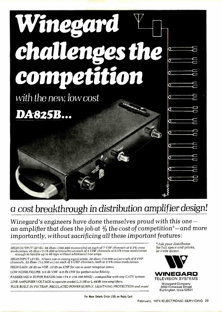
Winegardchallenges thecompetitionwith the new, low cosi
DA8251141,
4tts.
O
a cost breakthrough in distribution amplifier design!Winegard's engineers have done themselves proud with this one -an amplifier that does the job at 2/3 the cost of competition*-and moreimportantly, without sacrificing all these important features:
*Ask your distributorfor full specs and prices,or write direct.
HIGH OUTPUT LEVEL: 46 dbmv (200,000 microvolts) on each of 7 VHF channels at 0.5% crossmodulation; 45 dbmv (178,000 microvolts) on each of 5 UHF channels at 0.5% crass modulation... enough to handle up to 48 taps without additional line amps.HIGH INPUT LEVEL: Allows use in strong signal areas. 20 dbmv (10.000 uv) on each of 8 VHFchannels, 22 dbmv (12,000 uv) on each of 5 UHF channels, both at 0.5% cross modulation.
HIGH GAIN: 26 db on VHF, 23 db on UHF for use in most reception areas.
LOW NOISE FIGURE: 3.6 db VHF, 6.0 db UHF for perfect cclor fidelity.
PASSES MID & SUPER BANDS (108-174 & 216-300 MHZ)- compatible with any CATV system.
LINE AMPLIFIER VOLTAGE to operate model L -213B or L -483B line amplifiers.
PLUS BUILT-IN FM TRAP, REGULATED POWER SUPPLY, LIGHTNING PROTECTION and more!
WINEGARDTELEVISION SYSTEMS
Winegard Company3000 Kirkwood Street
Burlington, Iowa 52601
For More Details Circle (10) on Reply Card
February, 1974/ ELECTRONIC SERVICING 29
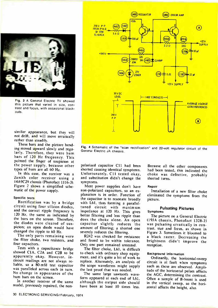
OREGULATOR 0 ERROR AMP
Fig. 3 A General Electric TV showedthis picture that varied in size, con-trast and focus, with occasional black-outs.
similar appearance, but they willnot drift, and will move erraticallyrather than steadily.
These bars and the picture bend-ing moved upward slowly and regu-larly. Therefore, they were humbars of 120 Hz frequency. Thispointed the finger of suspicion atthe power supply, because othertypes of hum are all 60 Hz.
In this case, the receiver was aZenith color receiver using a14A9C29 chassis (Photofact 1116-3).Figure 2 shows a simplified sche-matic of the power supply.
Specific testsRectification was by a bridge
circuit using four silicon diodes,and the correct ripple frequency is120 Hz, the same as indicated bythe bars on the screen. Therefore,the diodes were cleared of sus-picion; an open diode would havechanged the ripple to 60 Hz.
The only parts remaining werethe filter choke, two resistors, andfour capacitors.
Tests with a capacitance bridgeshowed CIA, C2A and C2B to beapparently okay. However, in -circuit readings are not always re-liable, so a 80-mfd test capacitorwas paralleled across each in turn.No change in appearance of thehum bars on the screen.
In another receiver of the samemodel, previously repaired, the non -
200V P -P 0FROM PIN 8OF T204
5.6FLYBACK
+140 V -I.
CD
30V DCLEVEL
T
200VPP
+30V
O
100
0.01
10yF
22 µF
L- +23V SUPPLY
I-- Y402 CONDUCTS-I
+22 V
SUPPLY
AVERAGE VOLTAGE
(ZERO REFERENCE)
O
Fig. 4 Schematic of the "scan rectification" and 22 -volt regulator circuit of theGeneral Electric JA chassis.
polarized capacitor C11 had beenshorted causing identical symptoms.Unfortunately, C11 tested okay,and substitution didn't change thesymptoms.
Most power supplies don't havenon -polarized capacitors, so an ex-planation is in order. Function ofthe capacitor is to resonate broadlywith L61. thus forming a parallel -
tuned circuit with maximumimpedance at 120 Hz. This givesbetter filtering and less ripple thandoes the choke alone. An opencapacitor slightly reduces theamount of filtering; a shorted oneseverely reduces the filtering.
R242 was checked for resistanceand found to be within tolerance.Only one part remained untested.
The filter choke. L61, is difficultto check with ordinary shop equip-ment, and it's quite a bit of work toreplace. Alternately, an analysis ofthe scope waveforms might supplythe last proof that was needed.
The same large sawtooth wave-form appeared at each end of L61,although the output side shouldhave been at least 10 times less.
Because all the other componentshad been tested, this indicated thechoke was defective, probablyshorted turns.
Repair
Installation of a new filter chokeeliminated the symptoms from thepicture.
Pulsating PicturesSymptoms
The picture on a General Electric(19JA chassis, Photofact 1328-2)was pulsating erratically in con-trast, size and focus, as shown inFigure 3. Sometimes it bloomed toa black raster. Decreasing thebrightness didn't improve thereception.
Background informationOrdinarily, the horizontal-sweep
circuit is at fault when symptomssuch as these are observed. Ampli-tude of the horizontal pulses affectsthe AGC, determining the contrast.Often a sample of B -boost is usedin the vertical sweep, so the hori-zontal affects the height, also.
30 ELECTRONIC SERVICING/February, 1974

Chart 1 In -Circuit Resistances
Component Forward biased Reverse biased
0400 (base -collector)0400 (collector -emitter)Y403 (diode)Y404 (zener)
7 ohms18 ohms10 ohms7 ohms
More than 1KMore than 1KMore than 1KMore than 250 ohms
However, I remembered the in-structor at a General Electricservice meeting telling us to watchout for a certain power -supply con-dition which also can cause thesesame symptoms. In addition to theusual interconnections, the JA -series GE chassis use "scan rectifi-cation" to supply extra DC volt-ages. Scan rectification merelymeans that horizontal pulses fromthe flyback transformer are recti-fied, filtered, regulated, and used tosupply DC to many circuits, such asIF's, horizontal oscillator, verticalstages, and many others. Obviously,any amplitude change of the hori-zontal pulses, or any variation ofthe regulated voltage, can affect theperformance in many ways.
Incidentally, it's interesting toconsider why pulses of 200 voltspeak -to -peak are required to pro-duce +30 volts after they are recti-fied (see Figure 4). The reason isfound in the nature of pulses. Zeroreference, or the average point ofthe waveform, is located near thelong space between pulses. There-fore, rectification of the positive -going part waveform (Figure 4B)above the zero line produces asmall DC voltage. If the polarity ofthe diode were reversed, rectifi-cation of the negative -going tipswould give a much larger DC vol-ige, perhaps -170 volts, or so.
After reviewing all this infor-mation, I decided it worthwhile tocheck out the condition of the+22 -volt supply.
Specific testsA quickly -made voltage measure-
ment revealed an excessive variationof the 22 -volt supply that changedin step with the visible symptoms.This voltage should be within ±2
volts of +22 volts, and should notchange more than .5 volt fromline -voltage variations between 110to 130 volts, or from brightnesschanges.
One of the first tests should beohmmeter measurements of Q400,Y403, and Y404, according to thetypical in -circuit readings shown inChart 1. If these readings don'tindicate a defect, Q402 should beremoved from the circuit to allowmeasurements of the base/emitterjunctions of Q402 and Q400.
In this example, the ohmmeterchecks were not conclusive. Onemore voltage measurement wasmade, across Y404, the zener diode.The voltage changed about thesame amount as that at the +122supply, although the +140 -voltsource did not vary. Now, this is afairly -simple regulator circuit inwhich the base voltage of Q400, theregulator transistor, is clamped bythe zener. Any variation of the
Fig. 5 A Motorola Quasar had dis-placed scanning lines over the entirepicture.
emitter voltage of Q400 (also 122 -volt supply) is a sensitive change ofbias. Q400 changes collector -emit-ter resistivity in an effort to keepthe emitter voltage .6 volt lower involtage than the base. Therefore,any change of zener voltage forcesthe +122 -volt supply to change thesame amount.
Zeners can be tested out -of -cir-cuit by connecting them through alimiting resistor to an externalpower supply. When the correctcurrent flows through the zener, thevoltage drop across it should be therated voltage. However, that's somuch trouble I just installed a re-
oic ON
SYNC FROMRORIE WEEP
SNAER ON
4
DRIVER OFF
OC
.00
'NOTCH ON
SWITCH
I REGULATOR raw«
Fig. 6 Block diagram of the JA panel electronic regulation used in the TS931 andTS938 chassis. Synchronization from the horizontal oscillator in the sweep circuitis necessary to prevent the displaced scanning lines. (boom's), of Motorola)
February, 19741 ELECTRONIC SERVICING 31

placement. No more blinking andpulsations.
Jagged Scanning LinesSymptoms
One Motorola Quasar with aTS938 chassis (Photofact 1299-2)showed pictures with a ripple effect(see Figure 5). A closer view re-vealed that some of the scanninglines were displaced horizontally.
Background informationCertain types of arcs (such as
those inside ceramic capacitors) inthe horizontal -sweep circuit cancause displaced scanning lines.However, they are displaced at ran-dom, not evenly as these were.
Next -best bet is a defect in thehorizontal AFC which changes thefiring time of the horizontal oscil-lator.
,r
Fig. 7 Waveform at the top is thenormal .8 -volt regulator sync signal,and the one at the bottom is the.1 -volt signal found in the defectiveQuasar.
Specific testsWaveforms of the horizontal -
AFC circuit indicated some disturb-ance, but no specific defect. I
probably would have wasted con-siderable time in futile tests, butthen I remembered this model usedan electronically -regulated high -frequency power supply, which wasdescribed on pages 16 and 17 ofElectronic Servicing for December,1971. This power supply (blockdiagram in Figure 6) operates atthe normal horizontal -scanning fre-quency. It is synchronized from thehorizontal oscillator of the receiverto prevent problems that the factorydidn't describe. I wondered if lackof synchronization or some otherdefect in the electronic powersupply might cause the displacedlines.
One test that seemed promising
Fig. 8 Another Zenith color set had anexcessively -dark picture without verti-cal or horizontal locking, caused byAGC failure.
HOR IZ RU15(5-0-1(
.260V
POSITIVE -GOINGVIDEO
470 pF R23I'AA
2.2 MO IF AGC
2.2 MO
220 pf 470 KO
©68A110GC SYNC SEP 52 6
470 KO
9 KO
260V -8.--.W --.--.1F1.2K 0 0.01
NEGATIVE -GOING
VIDEO
115 V-
20 pF
920 KO
0.01
47 KO
10 MO
.40 V
'AA 'AA.22 KO 470 KO
4',
SYNC OUTPUT
+26015 K r?
0.1
Fig. 9 AGC keying circuit of the Zenith 16Z7C17 color chassis.
was to compare the frequencies ofpower supply and horizontal sweepby use of a dual -trace scope. Sureenough, the waveform of the powersupply jumped back and forthwhen the scope was locked to thesweep frequency.
Next, the scope was connected topin 4 of the power supply tomeasure sync amplitude. Normalsync there, as shown in Figure 7,should be about .8 volt, but in thiscase the amplitude was only .1 volt.It seemed certain the low amplitudewas the reason for the lack ofsynchronism.
Ohmmeter tests of the 18K resis-tor (R813 external to the powersupply), R25 and T2 on the powersupply proved that R813 had in-creased drastically in resistance. In-stallation of a new resistor returnedthe picture performance to normal.
Dark And Unstable PictureSymptoms
As shown in Figure 8, the pictureproduced by the Zenith 16Z7C17chassis (Photofact 1014-3) was toodark and had no vertical or hori-zontal lock. Snow off -channel wasnormal. Adjustment of the AGCcontrol made the picture jump froma blank white raster to an over-loaded condition.
Background InformationAlthough this is an old circuit
(Figure 9), it continues to confusemany technicians because of themany signals entering and leavingthe tube. In the first place, the tubehas three functions: AGC keying,sync separation and noise inversion.Sync is of only secondary consider-ation here, so we'll not discuss it.
It helps in understanding theoperation of the AGC if we imaginethat the tube consists only of plate,grid and cathode (pins 2, 5 and 8).Now the circuit is a simple AGCkeyer having positive -going horizon-tal pulses applied to the platepositive -going video at the grid, ania variable DC voltage at the cath-ode to set the proper bias. Thepulses at the plate are rectified to adegree determined by the grid/cathode instantaneous bias, and thenegative voltage generated at theplate is filtered and used to controlthe gain of the IF and RF tubes.
To make the circuit noise im-mune, it's necessary to apply a
32 ELECTRONIC SERVICING/February, 1974

Fig. 10 Narrow width at the bottom,and some horizontal displacement ofscanning lines appeared on this Zenith20CC50.
negative -going video signal to theelectron stream only when the noiseexceeds the amplitude of sync tips.In this circuit, that is done byapplying both a positive DC voltageand negative -going video to thecontrol grid, pin 4. Positive voltagethrough R103 causes grid currentto flow, clamping the grid voltageonly slightly above the cathodevoltage. Most of the video signal isclipped by the grid current anddoes not interfere with the normalAGC action previously described.
But when a negative -going noisepulse reaches the grid, it forces thegrid temporarily to become morenegative than the cathode. Gridcurrent ceases, and this greatly in-creases the amplitude of the noisepulse; the cathode current is cutoff, and no AGC voltage is pro-duced at that time. Without thisaction, the tube would act on thenoise pulse at pin 5 as though thevideo signal had increased, causingmore negative AGC voltage, anddecreasing the gain of the tubes toproduce a picture having lower con-trast (white -out).
Noise -immune operation of thesync -separator circuit is somewhatsimilar. The pin -7 grid is thenormal one for sync separation, andthe noise signal at pin 4 (controlgrid common to both halves) cutsoff all sync. It's better to have nosync temporarily than to have noisepulses give false triggering of thesweep circuits.
Specific testsNormal -amplitude horizontal
pulses (about 140 volts p -p) werescoped at the plate, but a VTVMshowed a lack of negative DC volt-age there. For reasons yet un-
6186HORIZ OUTPUT
(OHS
HV REGULATOR
HORIZPULSES
120 pF
DEFECTIVE
0.001
1.5 MO
4.7 MO
0.0047
3 MO
2
220 pF
100 0 10 KO
.--pf-
8of
HV ADJUST
3M01.2 MO
1.2 MO
B -BOOST
DEFECTIVE
Fig. 11 HV-regulator and fail-safe circuits used in the 20CC50 Zenith.
known, the tube was not conduct-ing.
One of the simple, but effective,tricks in testing keyers is to connectgrid and cathode together, givingzero grid bias. If the circuit isnormal except for a keyer biasproblem, a high negative voltageshould be developed at the plate. 1used a test lead connecting pins 5and 8, but the plate remainedslightly positive (the normal voltagefor operation without. a station sig-nal). The result indicated a problemother than one of grid bias.
The tube had been changed, andthe screen voltage (pin 3) measuredokay. What did that leave? Wewould expect the DC voltage at pin5 to be wrong because of the over-load, and it was. But both the gridpin 4 and the cathode measuredover 100 volts. A quick ohmmetertest proved the AGC control wasopen.
Yes, a new AGC control and anormal adjustment cured the prob-lems.
Narrow Width At The BottomSymptoms
Scanning lines were displaced ingroups, and the picture was slightlynarrow at the bottom (Figure 10) ona Zenith 20CC50 (Photofact 1238-3).These effects decreased as thebrightness was increased,, until atfull brightness most of the symp-toms disappeared.
Background informationSay "trapezoidal picture" to al-
most any technician and he willreply "yoke". It's an automaticresponse. But a bad yoke doesn'tallow the trapezoid to disappearmerely because the brightness is
increased. That analysis was provedbecause the chassis was connectedto my test jig at the time.
Rumors have been circulated thatVDR's (varistors or voltage -sensitiveresistors) can cause such problems.This chassis has two VDR's, one inthe high -voltage regulation and onein the "fail safe" protective circuitwhich guards against operationwithout HV regulation (see Figure11).
One fast way to test a wholecircuit is to eliminate it and noticeif the trouble is gone.
To eliminate the protective effect,I connected a test lead across C181.There was no change, and thismeant that C181, 8159, R192,C133 and the VDR, 8193, were notthe source of the symptoms. If thetest had stopped the symptoms, it'slikely 8193 would have proved tobe defective.
Before we try the next test, weshould clarify the operation of thefail-safe protection circuit. Whenthe regulator (6JH5) has current,the diodes connected from cathodeto B+ are forward biased and actessentially as short circuits. Fromthe cathode, a sample of the posi-tive voltage there is brought throughR192 to the grid circuit of thehorizontal output tube. Normally,this would tend to drive the gridless negative. But rectificationaction of R193, the VDR, producesa negative voltage, also routed tothe output grid via R159. Ideally,the positive voltage through R192and the negative voltage throughR159 are equal and cancel at C181.There is no change of grid bias, sothe width and high voltage are notaffected.
(Continued on page 56)
February, 1974/ELECTRONIC SERVICING 33
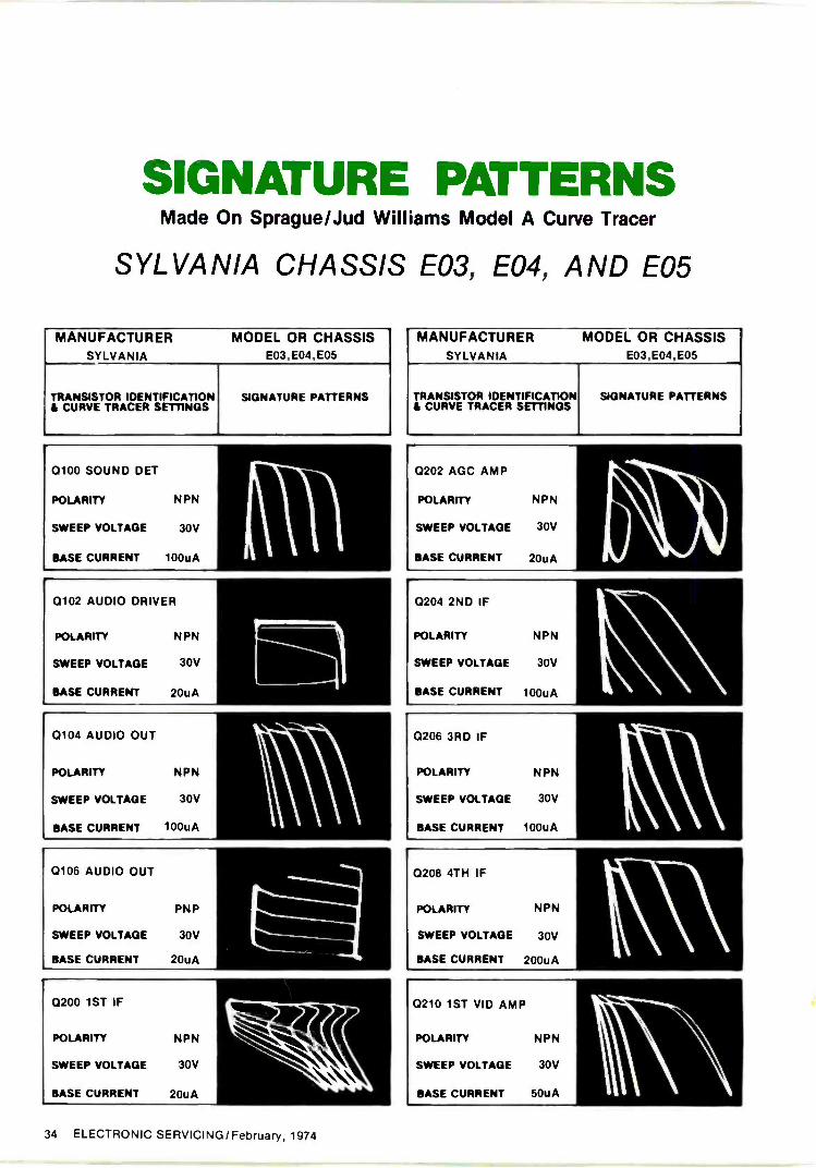
SIGNATURE PATTERNSMade On Sprague/Jud Williams Model A Curve Tracer
SYLVANIA CHASSIS E03, E04, AND E05
MANUFACTURER MODEL OR CHASSISSYLVANIA E03,E04,E05
TRANSISTOR IDENTIFICATION& CURVE TRACER SETTINGS
SIGNATURE PATTERNS
0100 SOUND DET
POLARITY NPN
SWEEP VOLTAGE 30V
BASE CURRENT 100uA
0102 AUDIO DRIVER
POLARITY NPN
SWEEP VOLTAGE 30V
BASE CURRENT 20uA
0104 AUDIO OUT
POLARITY NPN
SWEEP VOLTAGE 30V
BASE CURRENT 100uA
0106 AUDIO OUT
POLARITY P N P
SWEEP VOLTAGE 30V
BASE CURRENT 20uA
0200 1ST IF
POLARITY NPN
SWEEP VOLTAGE 30V
BASE CURRENT 20uA
MANUFACTURER MODEL OR CHASSISSYLVANIA E03,E04,E05
TRANSISTOR IDENTIFICATION$ CURVE TRACER SETTINGS
SIGNATURE PATTERNS
0202 AGC AMP
POLARITY NPN
SWEEP VOLTAGE 30V
BASE CURRENT 20uA
0204 2ND IF
POLARITY NPN
SWEEP VOLTAGE 30V
BASE CURRENT 100uA
0206 3RD IF
POLARITY NPN
SWEEP VOLTAGE 30V
BASE CURRENT 100uA
0208 4TH IF
POLARITY NPN
SWEEP VOLTAGE 30V
BASE CURRENT 200uA
0210 1ST VID AMP
POLARITY NPN
SWEEP VOLTAGE 30V
BASE CURRENT 50uA
34 ELECTRONIC SERVICING/February, 1974

Take a leaf from theMallory MoneyTree and save onfamous Mal!obi's:Our Mallobin benchtop organizers are worth manytimes their modest cost in keeping electronic com-ponents neatly sorted, labeled, protected and readyfor use. Now, you can save on buying them, too. For
MALLORY
Batteries Capacitors
instance, this PTC semiconductor Mallobin orga-nizer can be purchased at a special discount at yourMallory Distributor. Just present the Mallory MoneyTree coupon below.
MALLORY DISTRIBUTOR PRODUCTS COMPANYa division of P. R. MALLORY & CO. INC.Box 1284. Indianapolis. Indiana 46206: Telephone: 317-636-5353
Controls Security Products DURATAPEx Recorders Resistors SEMICONDUCTORS SONALERTik Switches Timers
OURATAPES and SONALERTOare registered trademarks of
R. Mallory & Co Inc
I MoneyTree CouponThis coupon valid through Sept. 1, 1974.Only one coupon valid on eachpurchase. This coupon not valid whereprohibited or taxed by law. Coupondoes not apply to sales tax, if applicable.
TO MALLORY DISTRIBUTORThis coupon redeemable for $1.00 credit towards the purchaseof any Mallory products or $1.00 in cash provided it is tenderedto Mallory Distributor Products Company, a division ofP. R. Mallory & Company Inc., Indianapolis, Indiana prior toOct. 1, 1974. Invoices showing purchase of Mallobin organizerssufficient to cover coupon must be shown on request.
Worth
Lj-- 0OFF
on anypurchase of any MalloryMallobin organizer at aMallory Distributor.
ES
For More Details Circle (4) on Reply Card
February, 1974/ELECTRONIC SERVICING 35

MANUFACTURER MODEL OR CHASSISSYLVANIA E03,E04,E05
TRANSISTOR IDENTIFICATION& CURVE TRACER SETTINGS
SIGNATURE PATTERNS
0211 VIDEO BUFFER
POLARITY PNP
SWEEP VOLTAGE 30V
BASE CURRENT 50uA
0212 AFC AMP
POLARITY NPN
SWEEP VOLTAGE 30V
BASE CURRENT 10uA
0214 AFC IF
POLARITY NPN
SWEEP VOLTAGE 30V
BASE CURRENT 100uA
Q302 VERT BUFFER
POLARITY NPN
SWEEP VOLTAGE 30V
BASE CURRENT 50uA
0304 VERT DRIVER
POLARITY NPN
SWEEP VOLTAGE 30V
BASE CURRENT 10uA
0306 VERT DRIVER
POLARITY PNP
SWEEP VOLTAGE 30V
BASE CURRENT 50uA
MANUFACTURER MODEL OR CHASSISSYLVANIA E03,E04,E05
TRANSISTOR IDENTIFICATION& CURVE TRACER SETTINGS
SIGNATURE PATTERNS
0308 VERT OUT
POLARITY NPN
SWEEP VOLTAGE 30V
BASE CURRENT 20uA
0310 VERT OUT
POLARITY NPN
SWEEP VOLTAGE
BASE CURRENT 20uA
30V
0400 AGC GATE
POLARITY NPN
SWEEP VOLTAGE 30V
BASE CURRENT 50uA
0402 HV LIME TO A, B TO G, C TO CA
POLARITY NPN
SWEEP VOLTAGE 30V1000uA
BASE CURRENT INVERTED
0404 HORIZ DRIVER
POLARITY NPN
SWEEP VOLTAGE 30V
BASE CURRENT 200uA
0406 HORIZ OUT
POLARITY NPN
SWEEP VOLTAGE 30V
BASE CURRENT 500uA
36 ELECTRONIC SERVICING/February, 1974
Ifyou had to namehe top electronics service company
who would it be?That s a tough question, be-causew.hen it comes to service,it's hard to compare apples toapples. Some companies offeryou many services-others veryfew. So before you make upyou- mild, we'd like to tell youabort some of the servicesPanasonic has developed.Services that can make both ourjobs a lot easier.Like offering complete tech-nical back-up information andassistance. We make availabledeta led service manuals onevery o-oduct we've eve- sold-over 1" 000 since 1959. And if
$
you need more information, callthe regional office in your area.And if ycu still want assistance,we'll send out one of our travel-ing field service specialists asyour personal problem solver.And there's more. We holdannual training seminars toacquaint you with our products,inside and out. And at industryconventions, you'll find aPanasonic representative toexplain our latest serviceadvances.At the core of it all are our prod-ucts. All designed with a highlevel of serviceability-meaning
winF
A . .mminmow
mems 41,
less time anc effort for you. Forinstance, our Quatrecolor TVsets scored 94.6 in the NEAserviceab lit'i tests of January'973. Anc we're continuallylooking for new improvements.-he fact is that Panasonic paysas much attention to service asit pays to sales. And everybodyis profiting-consumers dealersand service technicians.So befo-e you consider who toname as the top electrpnicsservice comoany, run throughthe facts. The more you knowabout Panasonic, the better it isfor everybody.
L
II 4-
Panasonicjust slighly ahead of our time
For More Details Cud. (28) on Reply card
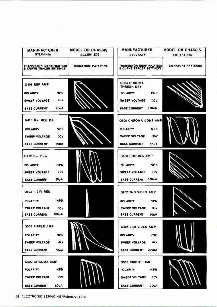
MANUFACTURER MODEL OR CHASSISSYLVANIA E03,E04,E05
TRANSISTOR IDENTIFICATION& CURVE TRACER SETTINGS
SIGNATURE PATTERNS
0408 REF AMP
POLARITY NPN
SWEEP VOLTAGE
BASE CURRENT 20uA
30V
0410 B + REG DR
POLARITY NPN
SWEEP VOLTAGE 30V
BASE CURRENT 50uA
0412 B + REG
POLARITY NPN
SWEEP VOLTAGE 30V
BASE CURRENT 50uA
0502 +24V REG
POLARITY NPN
SWEEP VOLTAGE 30V
BASE CURRENT 100uA
0504 RIPPLE AMP
POLARITY
SWEEP VOLTAGE
BASE CURRENT
NPN
30V
50uA
0602 CHROMA AMP
POLARITY NPN
SWEEP VOLTAGE 30V
BASE CURRENT 50uA
MANUFACTURER MODEL OR CHASSISSYLVANIA E03,E04,E05
TRANSISTOR IDENTIFICATION$ CURVE TRACER SETTINGS
SIGNATURE PATTERNS
0604 CHROMATHRESH DET
POLARITY
SWEEP VOLTAGE
PNP
30V
BASE CURRENT 500uA
N
0606 CHROMA CONT AMP
POLARITY
SWEEP VOLTAGE
BASE CURRENT
NPN
30V
20uA
0608 CHROMA AMP
POLARITY NPN
SWEEP VOLTAGE 30V
BASE CURRENT 500uA
0902 2ND VIDEO AMP
POLARITY NPN
SWEEP VOLTAGE 30V
BASE CURRENT 10uA
0904 3RD VIDEO AMP
POLARITY PNP
SWEEP VOLTAGE 30V
BASE CURRENT 200uA
kl
0906 BRIGHT LIMIT
POLARITY NPN
SWEEP VOLTAGE 30V
BASE CURRENT 20uA
38 ELECTRONIC SERVICING/February, 1974
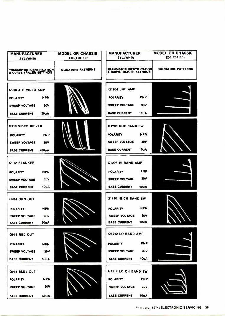
MANUFACTURER MODEL OR CHASSISSYLVANIA E03,E04,E05
TRANSISTOR IDENTIFICATION& CURVE TRACER SETTINGS
SIGNATURE PATTERNS
0908 4TH VIDEO AMP
POLARITY NPN
SWEEP VOLTAGE 30V
BASE CURRENT 20uA
0910 VIDEO DRIVER
POLARITY PNP
SWEEP VOLTAGE 30V
BASE CURRENT 200uA
0912 BLANKER
POLARITY NPN
SWEEP VOLTAGE 30V
BASE CURRENT 10uA
0914 GRN OUT
POLARITY NPN
SWEEP VOLTAGE 30V
BASE CURRENT 50uA
0916 RED OUT
POLARITY NPN
SWEEP VOLTAGE 30V
BASE CURRENT 50uA
0918 BLUE OUT
POLARITY NPN
SWEEP VOLTAGE 30V
BASE CURRENT 50uA
MANUFACTURER MODEL OR CHASSISSYLVANIA E03,EC4,E05
TRANSISTOR IDENTIFICATION& CURVE TRACER SETTINGS
SIGNATURE PATTERNS
01204 UHF AMP
POLARITY PNP
SWEEP VOLTAGE 30V
BASE CURRENT 10uA
01206 UHF BAND SW
POLARITY NPN
SWEEP VOLTAGE 30V
BASE CURRENT 10uA
01208 HI BAND AMP
POLARITY PNP
SWEEP VOLTAGE 30V
BASE CURRENT 10uA
01210 HI CH BAND SW
POLARITY NPN
SWEEP VOLTAGE 30V
BASE CURRENT 10uA
01212 LO BAND AMP
POLARITY PNP
SWEEP VOLTAGE 30V
BASE CURRENT 10uA
01214 LO CH BAND SW
POLARITY PNP
SWEEP VOLTAGE 30V
BASE CURRENT 10uA
February, 1974/ELECTRONIC SERVICING 39
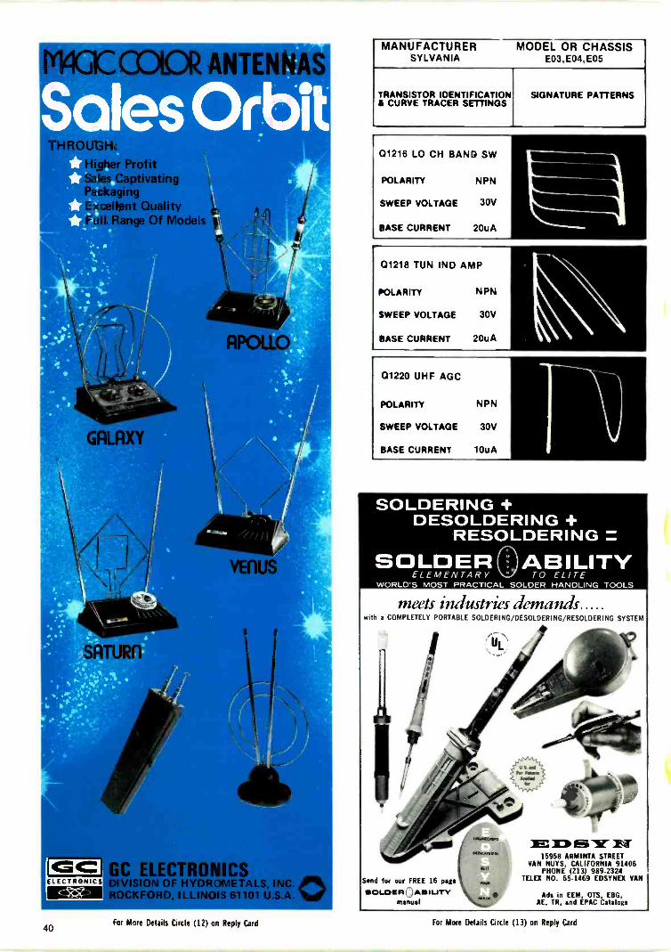
-1=cELECTRONICS
r Profitptivating9
ent QualityRange Of Mo
GC ELECTRONICSDIVISION OF HYDROMETALS, INC. 0ROCKFORD, ILLINOIS 61101 U.S.A.
Send for our FREE 16 park:.SOEROLCI AISIUTY
manualmm
MANUFACTURER MODEL OR CHASSISSYLVANIA E03,E04,E05
TRANSISTOR IDENTIFICATION& CURVE TRACER SETTINGS
SIGNATURE PATTERNS
01216 LO CH BAND SW
POLARITY NPN
SWEEP VOLTAGE 30V
BASE CURRENT 20uA
01218 TUN IND AMP
POLARITY NPN
SWEEP VOLTAGE 30V
BASE CURRENT 20uA
01220 UHF AGC
POLARITY NPN
SWEEP VOLTAGE 30V
BASE CURRENT 10uA
SOLDERING +DESOLDERING +
RESOLDERINGSOLDER ABILITY
ELEMENTARY TO ELITEWORLD'S MOST PRACTICAL SOLDER HANDLING TOOLS
meets industries demandswith a COMPLETELY PORTABLE SOLDERING/DESOLDERING/RESOLDERING SYSTEM
4s;066, 10111,
1WOKUMm E 1:0 IS15958 ARMINTA STREET
VAN NUYS, CALIFORNIA 91406PHONE (213) 989-2324
TELEX NO. 65-1469 EDSYNEX VAN
Ads in EEM, OTS, EBG,AE, TR, and EPAC Catalogs
40Fdr More Details Circle (12) on Reply Card For More Details Circle (13) on Reply Card
READERSERVICE CARDElectronic ServicingUse the handy card below to obtain free catalogs andliterature ... and to subscribe or renew your subscription.
Read instructions carefully.
As a service to its readers, ELECTRONICSERVICING makes the card below avail-able for your convenience in obtainingcurrent manufacturer's literature.To use the card, simply:a. Circle the numbers corresponding to the
numbers of the items about which youwould like to receive additional infor-mation.
b. Print your name and and checkyour occupation.
c. Include ZIP code-requests may not befilled without it.
d. Tear out lower half of this insert andplace in mailbox.
Note the deadline date-Requests re-ceived after this cannot be filled.
vw Free catalogs & literature
FEBRUARY, 1974OFFER EXPIRES MAY 1, 1974
Please indicate number of items you have circled-.
Subscribe or renew your present subscrip-tion to the nation's favorite electronic serv-icing magazine .. . ELECTRONIC SERVIC-ING (formerly PF REPORTER).
Now with expanded editorial coverage ofthe entire electronic servicing business,ELECTRONIC SERVICING is more valu-able to you than ever! Monthly it bringsyou the latest solutions to service prob-lems on home entertainment electronics,including concise, timely coverage of newtesting methods, product reports and prac-tical service procedures!
Start ELECTRONIC SERVICING coming bysending in this order form .. . TODAY!
Subscription offer
1 2 3 4 5 6 7 8 9 10 11 12 13 14 15 16 17 18
19 20 21 22 23 24 25 26 27 28 29 30 31 32 33 34 35 36
37 38 39 40 41 42 43 44 45 46 47 48 49 50 51 52 53 54
55 56 57 58 59 60 61 62 63 64 65 66 67 68 69 70 71 72
73 74 75 76 77 78 79 80 81 82 83 84 85 86 87 88 89 90
91 92 93 94 95 96 97 98 99 100 101 102 103 104 105 106 107 108
109 110 111 112 113 114 115 116 117 118 119 120 121 122 123 124 125 126
127 128 129 130 131 132 133 134 135 136 137 138 139 140 141 142 143 144
145 146 147 148 149 150 151 152 153 154 155 156 157 158 159 160 161 162
163 164 165 166 167 168 169 170 171 172 173 174 175 176
Print plainly or type below:
Name
Firm
Firm Address
City State ..... _ Zip--._......
Did you receive this issue through E Distributor D Subscription
Subscription Offer
Enter my subscription to ELECTRONIC SERVICING
El 3 Years $13.00 2 Years $10.00 El I Year $6.00
0 Bill Me f] Remittance Enclosed 0 Extend Present Subscription
IMPORTANT! Please check your business classification.
Tye! of Business
Check One
A. E Independent Electronic Service OrganizationB. 0 Retailer with Electronic Service Department.C. D Independent or Self -Employed Service
TechnicianD. D Electronics, Radio, TV ManufacturerE. E Industrial Electronic ServiceF. E Wholesale, Jobber, DistributorG. E Other (Specify)
Be sure you have checked one box in each column above!
Position
Check One
H. E Owner, ManagerI. D Ser. ManagerJ. 0 TechnicianK. Other
WRITING TOElectronic Servicing?
Help us prevent delayIf your comment or question is about ...YOUR SUBSCRIPTIONChanges of address or any questions aboutyour subscription should be sent to theaddress at right. Please advise us of achange of address at least 4-6 weeks inadvance of your move, if possible.
ANY OTHER SUBJECTIf you have a comment or question aboutan article, condition in the industry, a ser-vice tip or problem, need a part or sche-matic, or would like to pass along infor-mation about an industry oriented event,etc., write to:
Evelyn Rogers, Circulation ManagerELECTRONIC SERVICING1014 Wyandotte St.Kansas City, Mo. 64105
Carl Babcoke, Managing EditorELECTRONIC SERVICING1014 Wyandotte St.Kansas City, Mo. 64105
6 CENTS
POSTAGE
REQUIRED
EleCir011iC ServicingP.O. Box 2512
Clinton, Iowa 52732
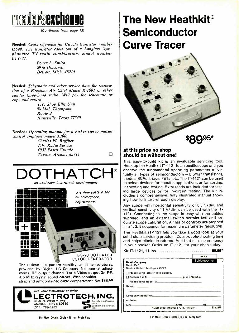
%exchange(Continued from page 12)
Needed: Cross reference .for Hitachi transistor number1S699. The transistor came out of a Longines Sym-phonette TV -radio combination, model numberLTV -77.
Ponce L. Smith2978 HolcombDetroit, Mich. 48214
Needed: Schematic and other service data for restora-tion of a Firestone Air Chief Model R-1661 or othersimilar three -band radio. Will pay for schematic orcopy and return.
T.V. Shop Ellis Unit(70 Maj. ThompsonRoute 3Huntsville, Texas 77340
Needed: Operating manual for a Fisher stereo mastercontrol amplifier model X100.
Charles W. RuffnerT.V. Radio Service4032 Paseo GrandeTucson, Arizona 85711 0
DOTHATCH®an exclusive Lectrotech development
iME1111.1.11111111I000vaaoi11111111111111110E111
IMMO=
11+6
Mel iiiMOMENOMEM
one new pattern forall covergenceadjustments
BG-20 DOTHATCHCOLOR GENERATOR
The ultimate in pattern stability, at all temperatures,provided by Digital I C Counters. No internal adjust-ments. RF output channel 3 or 4 Video output 3v. P -P.4.5 MHz crystal sound carrier. With shoulderstrap and self-contained cable compartment. Net 129.50
See your distributor or write
LECTROTECH, INC.5810 N. Western Ave, ..I Avadabie in CanadaChicago, Illinois 60659 R._
In c
from
1312) 769-6262 Off-.11. Superior Elecrrn,
The New Heathkit®SemiconductorCurve Tracer
at this price no shopshould be without one!This easy -to -build kit is an invaluable servicing tool.Hook up the Heathkit IT -1121 to an oscilloscope and youobserve the fundamental operating parameters of vir-tually all types of semiconductors - bipolar transistors,diodes, SCRs, triacs, FETs, etc. The IT -1121 can be usedto select devices for specific applications or for sorting,inspecting and testing. Extra leads are included for test-ing large devices or for in -circuit testing. The kit in-cludes a comprehensive, fully illustrated manual show-ing how to interpret each display.Any scope with horizontal sensitivity of 0.5 V/div. andvertical sensitivity of 1 V/div. can be used with the IT -1121. Connecting to the scope is easy with the cablessupplied, and an external switch permits fast and ac-curate scope calibration. All major controls are steppedin a 1, 2, 5 sequence for maximum parameter resolution.
The Heathkit IT -1121 lets you take a good look at yoursolid-state servicing problem. Cuts trouble -shooting timeand helps eliminate returns. And that can mean moneyin your pocket. Order an IT -1121 for your shop today.
Kit 1T-1121, 11 lbs.
rHeath CompanyDept. 25-2Benton Harbor, Michigan 49022
0 Please send latest Heath catalog.0 Enclosed is plus shipping.
89.95*HEATH
Scleurnbc tiler
Please send model(s)
Name
Title
Company/ Institution
Address
City State lip'Mail order prices; F.O.B. factory. TE-302R
For More Details Circle (31) on Reply Card For More Details Circle (14) on Reply Card
Prevent thosecostly callbacks
Practice preventive maintenance tocatch most questionable parts be-fore they go completely bad andcost you a callback. Justify their re-placement to any consumerists byknowing precisely the defect andwhy the component should havebeen replaced.
You want your customers to callyou regularly for TV service. That'sjust good business. But those cus-tomers are going to blame you ifthey are forced to call you toooften.
Of course, set owners can't beexpected to understand the legiti-mate reasons about how a seconddefect (unrelated to the originalone) can pop up in the near future.On the other hand, you certainlycan't guarantee anything except theparts replaced and the adjustmentsyou've made. Often you must makegood beyond your responsibilitylthus losing money), or anger acustomer who then blackens yourreputation.
There is a solution for some ofthese problems. It's called "preven-tive maintenance". That's what onefilling -station attendant didn't do tomy car when it was serviced justthree days before the fan beltbroke, stranding me miles from agarage. At the opposite extremewas the time another attendant toldme positively I should have the fanbelt (of a different car) replaced. Iexamined the belt and found nocracks, cuts, or evidence of wear, soI refused. That "bad" belt lastedthree more years. I just missedbeing victimized. Needless to say, Ididn't go back to that station.
The way to success is not only toreplace the components causing thepresent complaint, but also to findother parts that are beginning todeteriorate and replace them beforethey cost you a callback. However,don't do any unnecessary repairs.Aside from moral considerations,
By John Rozsaand Carl Babcoke
this is for your own protection fromprosecution by some overly -ambi-tious district attorney or consumer-ist. It's Just as wrong to do too littleas it is to do repairs that are notneeded.
Don't Hit -And -RunIt's easy to hurry so fast that we
overlook additional problems. Onlya few extra minutes are needed tofind many potential trouble spots orbelow -par performances of the re-ceiver being checked. If you takecare of them during the first repair,you have made extra money, avoid-ed a callback, and insured a happycustomer.
Make up a checklist, somethinglike this one, to guide you infinding secondary troubles: If the original complaint wasabout the picture, test the soundreproduction for volume, tone qual-ity, hum and noise; Test other tubes in addition tothe one main culprit. Tap them asa test for intermittents or arcs; Try the picture quality on allavailable channels. Recommend anoutside antenna or antenna repairs,if needed; Rock the channel selector tocheck for corroded contacts; If the receiver has a past historyof excessive tube replacements,measure the line voltage; Give the chassis an "eyeball"examination for burned resistors orgassy tubes; If the set is a color receiver, turndown the color control and look forblotchy purity and misconvergence; Diagnose color tint and satura-tion, and look for abnormal beatpatterns in the color; and Try the height, linearity and allcustomer -operated controls for noisyor intermittent operation, then resetthe height and linearity.
To help you decide which partsshould be and which should not bereplaced, we offer the followingpractical suggestions.
Facts And Myths About Tubes"Tube testers provide accurate
readings of all important conditionsof tubes." MYTH. No tube testerdesigned for the service tradechecks tubes under the same condi-tions that are encountered in receiv-ers. This is particularly importantwith tubes used in the vertical andhorizontal sections of TV receivers,because those tubes are operatedwith high pulse voltages which areimpractical and unsafe to providein a tester.
"Every technician should haveand use a tube tester." FACT.Tube testers can be very valuable infinding dead, weak, intermittent,and gassy tubes, if we understandtheir limitations. For one thing, theindication of a short should beinterpreted. A 2-megohm leakagefrom control grid -to -screen grid isvery important, but the same leak-age from heater -to -cathode is usual-ly of no consequence.
"All tubes showing a blue glowshould be replaced." MYTH. Blueglow on the inside of the metallicelements of small tubes does indi-cate gas, and that's reason for re-placement. However, blue glow onlyon the glass is fluorescence and hasnothing to do with the condition orlife -expectancy of the tube.
"Any tube producing intermittentoperation when it is tapped shouldbe replaced." Both FACT andMYTH. The tube might be inter-mittent, but perhaps the shocks aremoving something on the board. Orthe socket might be corroded. Totest for this possibility, gently rotatethe tube in its socket. If this move-ment also triggers the intermittent,the socket is at fault, not the tube,and it should be cleaned or re-placed. Tuner cleaner applied toeach socket pin a drop at a timefrom the tip of a small screwdriveroften is effective in stopping inter-mittents. Don't spray the entirearea.
44 ELECTRONIC SERVICING/February, 1974
Facts And MythsAbout Cleaning Tuners
"To repair any tuner intermittent,fog large quantities of any bargain -counter spray cleaner into a holethrough the shields." MYTH. Firstof all, many intermittents are notcaused by corroded switch contacts,so spraying would be futile. Second-ly, not all sprays are safe and effec-tive to use. You should investigateto find a brand that does not attackplastic parts and does not detunethe oscillator frequency. Use carenot to get any spray inside neutral-izing capacitors because even excel-lent kinds of spray might cause theRF stage to oscillate (give horizontalblack bars) on some high -bandstations.
It's advisable to obtain the cus-tomer's okay before spray cleaninga tuner. Explain that some tunerproblems cannot be cleared thisway, but require disassembly of thetuner, with cleaning and lubrica-tion. Perhaps you could gain thecustomer's confidence by offering toapply the charge for spray cleaningagainst any additional tuner clean-ing needed within a short period oftime.
By the way, variable controlswithout DC voltages across themusually respond well to cleaning.Just get some cleaner on the ele-ment and turn the control end -to -end a few times. However, controlscarrying DC (such as height, linear-ity,' etc.) should be replaced if theybecome intermittent.
Facts And Myths AboutResistors And Capacitors
"Resistors with bulges should al -
IT'S OUR N TUNER! LAST TIMETHFY CHARGED $15.75 TO CLEAN IT!"
ways be replaced without any moretesting." Partly FACT and partlyMYTH. A composition -type resistorwith a bulge or irregularity only onone side in one area probably is anormal resistor that was poorlymolded during manufacture. If itchecks within tolerance, don't re-place it. A resistor that is withintolerance but shows some change ofbody and stripe colors from exces-sive heat usually doesn't requirereplacement. However, any resistorsthat appear burned and measureeither higher or lower than toler-ance should always be replaced.
"Resistors of values higher thanI megohm are more likely to changeslowly to a higher value than arelower values. Resistors of only afew -thousand ohms don't driftmuch from aging, but occasionallyopen without being overloaded."FACT. I can't explain why, butthese statements are verified byboth observation and heat tests.
"Resistors of the composition -type seldom become intermittent,but they sometimes become noisy."FACT. One simple test of a noisyresistor is to spray it with coolant.A noticeable change of noise levelindicates the resistor is the sourceof the noise.
"Some capacitor defects will notshow up on conventional test equip-ment." FACT. Open capacitors,and intermittently -open capacitors,can be found with capacitancemeters and bridges, or with scopesby waveform analysis. But ohm-meters with a low -voltage batteryoften cannot show leakage of acapacitor, particularly those capaci-tors with leakages made worse byrising temperature.
One rare defect is a capacitor(usually a ceramic type) that leaksin an intermittent way similar to anarc, and does so only with specificconditions of voltage and tempera-ture. We challenge the people whotry to entrap technicians to test thiskind of defect!
"Any capacitor of the same volt-age and capacitance rating makes asuitable replacement." MYTH. Inaddition to any obvious physicalsize differences or wrong spacing oflead wires, such characteristics as adifferent temperature coefficient,lower "0", drifting long-term sta-bility, or excessive leakage mightmake some types a bad bet. Of
course, a superior type can be used,at a higher price. Mylar-dielectriccapacitors are better than papertypes, and mica or zero -temperatureceramics operate fine instead ofgeneral replacement ceramics. Justdon't try to substitute the other wayaround. For example, an ordinaryceramic should not be installed toreplace a silver mica.
"A larger value of capacitancealways works better." Partly FACTand partly MYTH. In a few appli-cations (filters and bypasses), alarger value might help the per-formance. But in almost all otheruses, only the original values shouldbe used as replacements.
SummaryEvery callback is costly in both
time and money. If you make asecond charge, the customer proba-bly is infuriated. But, if you don'tcharge again, you lose money.
Of course, it's possible to "shot-gun" whole circuits and installmany parts and tubes in an all-outeffort to avoid callbacks. However,that's expensive, and also a danger-ous practice in this age of emotionalconsumerism.
We recommend that every tech-nician test the parts more carefully,so he can be positive each rejectedpart is actually defective. Then thegeneral defect should be listed withthe part on the invoice. This simplestep aids memory, and gives ameasure of protection if a questionarises later asking why the part wasreplaced.
"BUT THE PICTURE ISN'T THE ONLY THINGTHAT'S FLIPPING!"
February, 1974/ELECTRONIC SERVICING 45
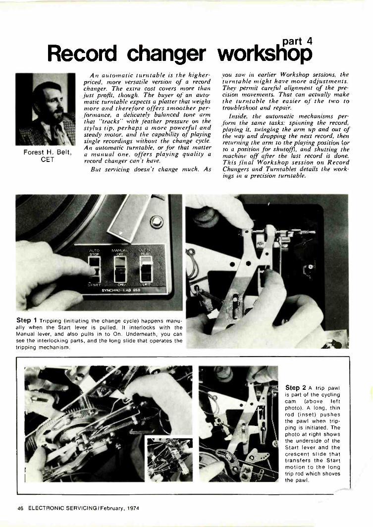
Record changer workstiOP
Forest H. Belt,CET
An automatic turntable is the higher -priced, more versatile version of a recordchanger. The extra cost covers more thanjust profit, though. The buyer of an auto-matic turntable expects a platter that weighsmore and therefore offers smoother per-formance, a delicately balanced tone armthat "tracks" with feather pressure on thestylus tip, perhaps a more powerful andsteady motor, and the capability of playingsingle recordings without the change cycle.An automatic turntable, or for that mattera manual one, offers playing quality arecord changer can't have.
But servicing doesn't change much. As
Step 1 Tripping (initiating the change cycle) happens manu-ally when the Start lever is pulled. It interlocks with theManual lever, and also pulls in to On. Underneath, you cansee the interlocking parts, and the long slide that operates thetripping mechanism.
you saw in earlier Workshop sessions, theturntable might have more adjustments.They permit careful alignment of the pre-cision movements. That can actually makethe turntable the easier of the two totroubleshoot and repair.
Inside, the automatic mechanisms per-fi9rm the same tasks: spinning the record,playing it, swinging the arm up and out ofthe way and dropping the next record, thenreturning the arm to the playing position (orto a position for shutoff), and shutting themachine off after the last record is done.This final Workshop session on RecordChangers and Turntables details the work-ings in a precision turntable.
Step 2 A trip pawlis part of the cyclingcam (above leftphoto). A long, thinrod (inset) pushesthe pawl when trip-ping is initiated. Thephoto at right showsthe underside of theStart lever and thecrescent slide thattransfers the Startmotion to the longtrip rod which shovesthe pawl.
46 ELECTRONIC SERVICING/February, 1974
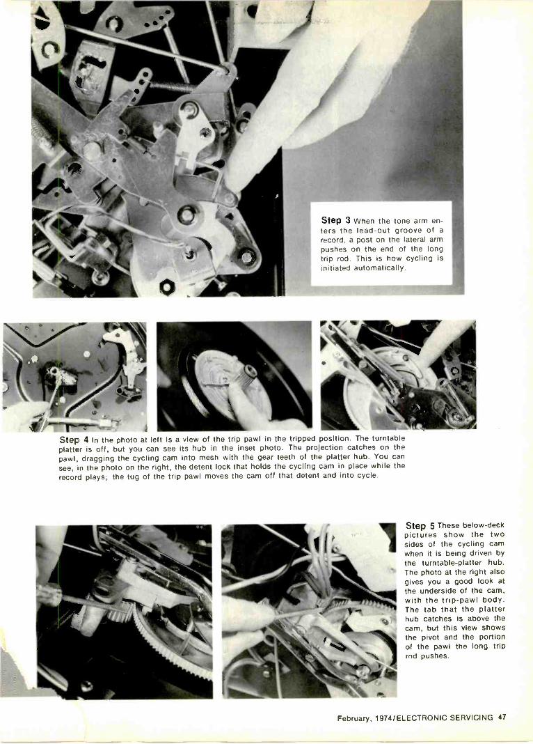
Step 3 When the tone arm en-ters the lead -out groove of arecord, a post on the lateral armpushes on the end of the longtrip rod. This is how cycling isinitiated automatically.
4
Step 4 In the photo at left is a view of the trip pawl in the tripped position. The turntableplatter is off, but you can see its hub in the inset photo. The projection catches on thepawl, dragging the cycling cam into mesh with the gear teeth of the platter hub. You cansee, in the photo on the right, the detent lock that holds the cycling cam in place while therecord plays; the tug of the trip pawl moves the cam off that detent and into cycle.
Step 5 These below -deckpictures show the twosides of the cycling camwhen it is being driven bythe turntable -platter hub.The photo at the right alsogives you a good look atthe underside of the cam,with the trip -pawl body.The tab that the platterhub catches is above thecam, but this view showsthe pivot and the portionof the pawl the long triprod pushes.
February, 1974/ELECTRONIC SERVICING 47

Step 6 From a groove in the cam, thecycling cam drives several cycling slides.The groove engages a post that is part ofthe main cycling slide.
Step 7 This slide takes care of the lifting act:on of the tone arm. If youencounter faulty lifting, carry your diagnosis to this slide and its associatedassemblies. Watch for springs that might have dropped out of place or might bestretched.
Step 8 Lateral motion (swinging out and back) of the tone armmainly is accomplished by the triangular -shaped slide lever. The insetphoto shows the assemblies it acts upon. The post, indicated byforefinger at the right, is part of the tone -arm lateral -movement arm;it's what hits the trip rod at the end of the record.
Step 9 This spindle is removable-as are mostturntable spindles-and has a long activator rod.Movement of the activator rod is sideways, mov-ing the pushoff tab out and back, and then a littlefurther until it protrudes in the other direction.This far -forward motion senses any more recordson the stack; if none, the machine shuts off afterthe record that just dropped has played.
48 ELECTRONIC SERVICING/February, 1974
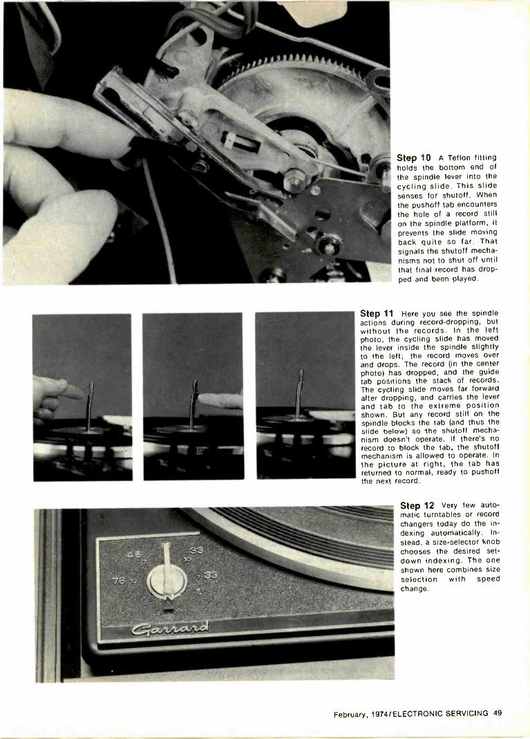
Step 10 A Teflon fittingholds the bottom end ofthe spindle lever into thecycling slide. This slidesenses for shutoff. Whenthe pushoff tab encountersthe hole of a record stillon the spindle platform, itprevents the slide movingback quite so far. Thatsignals the shutoff mecha-nisms not to shut off untilthat final record has drop-ped and been played.
Step 11 Here you see the spindleactions during record -dropping, butwithout the records. In the leftphoto, the cycling slide has movedthe lever inside the spindle slightlyto the left; the record moves overand drops. The record (in the centerphoto) has dropped, and the guidetab positions the stack of records.The cycling slide moves far forwardafter dropping, and carries the leverand tab to the extreme positionshown. But any record still on thespindle blocks the tab (and thus theslide below) so the shutoff mecha-nism doesn't operate. If there's norecord to block the tab, the shutoffmechanism is allowed to operate. Inthe picture at right, the tab hasreturned to normal, ready to pushoffthe next record.
Step 12 Very few auto-matic turntables or recordchangers today do the in-dexing automatically. In-stead, a size -selector knobchooses the desired set -
down indexing. The oneshown here combines sizeselection with speedchange.
February, 1974/ELECTRONIC SERVICING 49
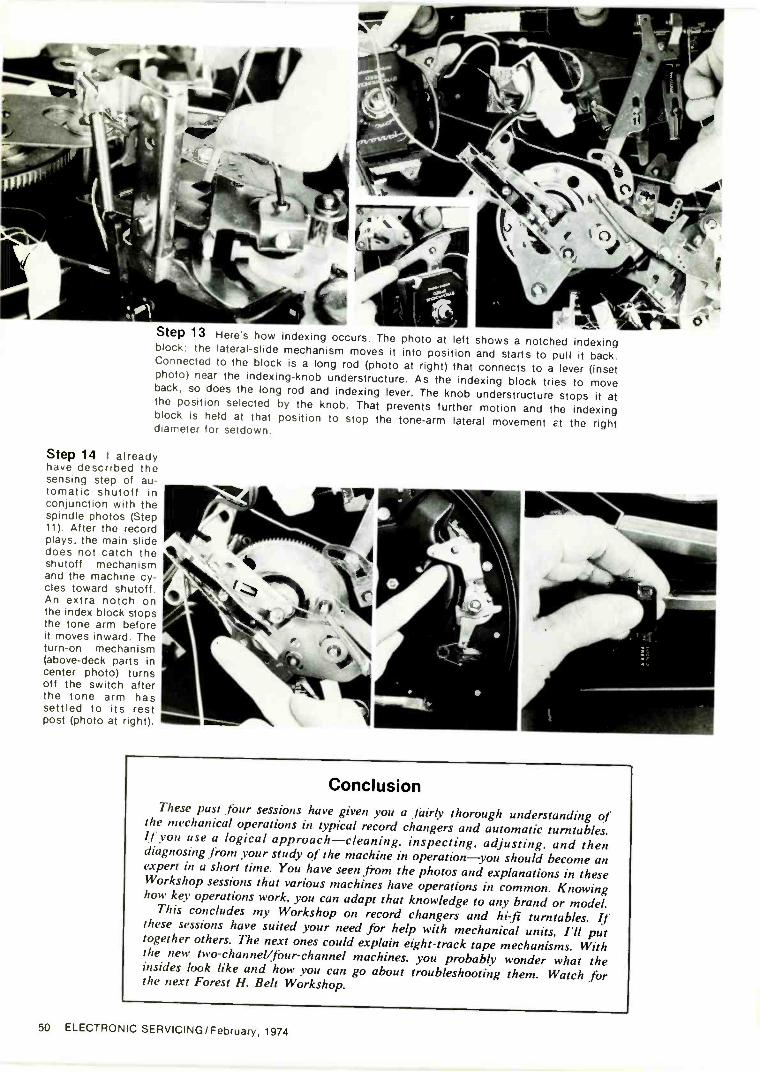
PkStep 13 Here's how indexing occurs. The photo at left shows a notched indexingblock, the lateral -slide mechanism moves it into position and starts to pull it back.Connected to the block is a long rod (photo at right) that connects to a lever (insetphoto) near the indexing -knob understructure. As the indexing block tries to moveback, so does the long rod and indexing lever. The knob understructure stops it atthe position selected by the knob. That prevents further motion and the indexingblock is held at that position to stop the tone -arm lateral movement Et the rightdiameter for setdown.
Step 14 I alreadyhave described thesensing step of au-tomatic shutoff inconjunction with thespindle photos (Step11). After the recordplays, the main slidedoes not catch theshutoff mechanismand the machine cy-cles toward shutoff.An extra notch onthe index block stopsthe tone arm beforeit moves inward. Theturn -on mechanism(above -deck parts incenter photo) turnsoff the switch afterthe tone arm hassettled to its restpost (photo at right).
ConclusionThese past four sessions have given you a fairly thorough understanding of
the mechanical operations in typical record changers and automatic turntables.If you use a logical approach-cleaning, inspecting, adjusting, and thendiagnosing from your study of the machine in operation-you should become anexpert in a short time. You have seen from the photos and explanations in theseWorkshop sessions that various machines have operations in common. Knowinghow key operations work, you can adapt that knowledge to any brand or model.
This concludes my Workshop on record changers and hi-fi turntables. Ifthese sessions have suited your need for help with mechanical units, I'll puttogether others. The next ones could explain eight -track tape mechanisms. Withthe new two-channel/four-channel machines, you probably wonder what theinsides look like and how you can go about troubleshooting them. Watch forthe next Forest H. Belt Workshop.
50 ELECTRONIC SERVICING/February, 1974
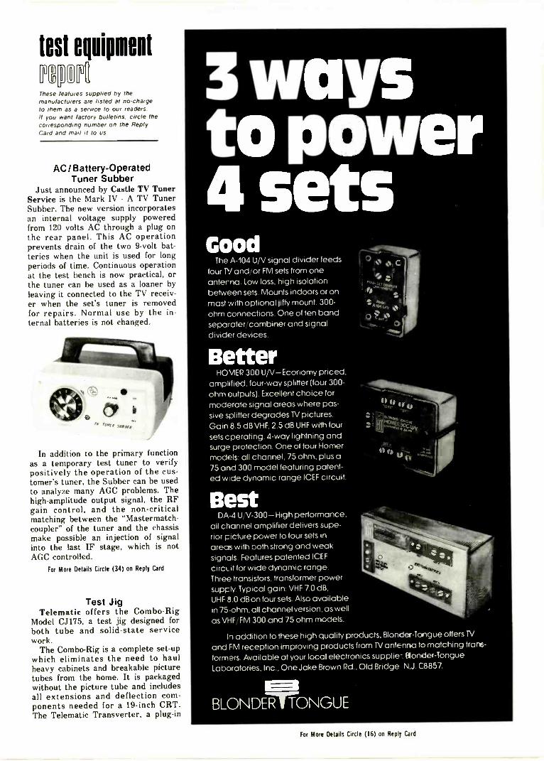
test equipmeot
These features supplied by themanufacturers are listed at no -chargeto them as a service to our readersif you want factory bulletins, circle thecorresponding number on the ReplyCard and mail it to us.
AC/Battery-OperatedTuner Subber
Just announced by Castle TV TunerService is the Mark IV - A TV TunerSubber. The new version incorporatesan internal voltage supply poweredfrom 120 volts AC through a plug onthe rear panel. This AC operationprevents drain of the two 9 -volt bat-teries when the unit is used for longperiods of time. Continuous operationat the test bench is now practical, orthe tuner can be used as a loaner byleaving it connected to the TV receiv-er when the set's tuner is removedfor repairs. Normal use by the in-ternal batteries is not changed.
In addition to the primary functionas a temporary test tuner to verifypositively the operation of the cus-tomer's tuner, the Subber can be usedto analyze many AGC problems. Thehigh -amplitude output signal, the RFgain control, and the non -criticalmatching between the "Mastermatch-coupler" of the tuner and the chassismake possible an injection of signalinto the last IF stage, which is notAGC controlled.
For More Details Circle (34) on Reply Card
Test JigTelematic offers the Combo -Rig
Model CJ175, a test jig designed forboth tube and solid-state servicework.
The Combo -Rig is a complete set-upwhich eliminates the need to haulheavy cabinets and breakable picturetubes from the home. It is packagedwithout the picture tube and includesall extensions and deflection com-ponents needed for a 19 -inch CRT.The Telematic Transverter, a plug-in
3 waysto power4 setsGood
The A-104 U V signal divider feedsfour P1 and or FM sets from oneanterna. Low loss high isolationbetween sets Mounts indoors or onmast with optional jiffy mount 300 -ohm connections. One of ten bandseparater combiner and signaldivider devices.
BetterHOMER 300 U V-Economy priced.
amplified four-way splitter (four 300 -ohm outputs) Excellent choice formoderate signal areas where pas-sive splitter degrades TV pictures.Gain 8.5 dB VHF 2 5 dB UHF with foursets cperating 4 -way lightning andsurge protection. One of four Homermodels all channel. 75 ohm. plus a75 and 300 model featuring patent-ed w de dynamic range ICEF circuit.
BestDA -4 U V-300-High performance
all channel amplifier delivers supe-rior picture power to four sets inareas with both strong and weaksignals. Features patented ICEFcircL it for wide dynamic rangeThree transistors, transformer powersupply Typical gain VHF 7.0 dB.UHF 8 0 dB on four sets Also availablein 75 ohm all channel version, as wellas VHF FM 300 and 75 ohm models
In addition to these high quality products. Blonder -Tongue offers 1V
and FM reception improving products from 1V antenna to matching trans-
formers Available at your local electronics supplie- Blonder -TongueLaboratories. Inc One Jake Brown Rd Old Bridge NJ C8857
BLONDER TONGUE
For More Details Circle (16) on Reply Card
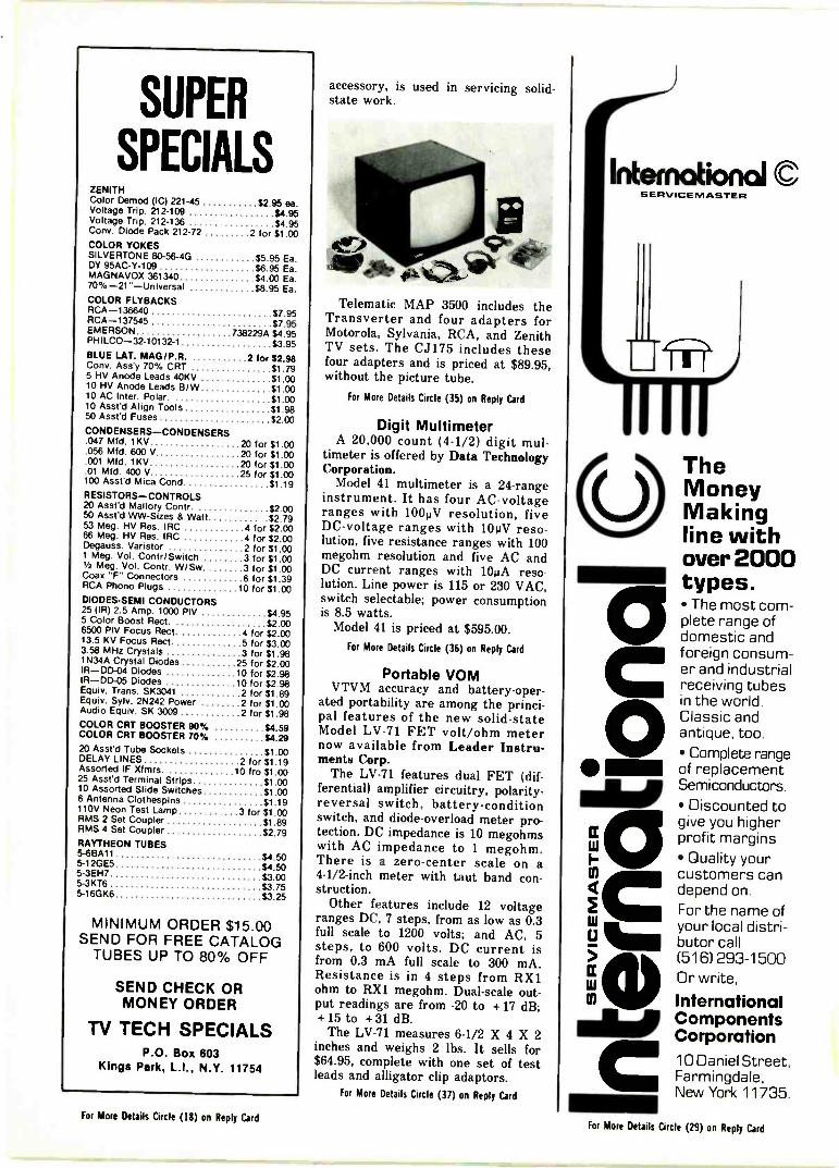
SUPER
SPECIALSZENITHColor Demod (IC) 221-45 $2.95 ea.Voltage Trip. 212-109 $4.95Voltage Trip. 212-136 $4.95Cony. Diode Pack 212-72 2 for $1.00COLOR YOKESSILVERTONE 80-56-4G $5.95 Ea.DY 95AC-Y-109 $6.95 Ea.MAGNAVOX 361340 $4.00 Ea.70 % -21" -Un iversal $8.95 Ea.COLOR FLYBACKSRCA -136640 $7.95RCA -137545 $7.95EMERSON 738229A $4.95PHILCO-32-10132-1 $3.95BLUE LAT. MAG/P.R. 2 for $2.98Cons. Ass'y 70% CRT $1 795 HV Anode Leads 40KV $1.0010 HV Anode Leads BIW $1.0010 AC Inter. Polar. $1.0010 Asst'd Align Tools $1.9850 Asst'd Fuses $2.00CONDENSERS -CONDENSERS.047 Mfd. 1KV 20 for Si 00.056 Mfd. 600 V 20 for Si 00.001 Mfd. 1KV 20 for Si 00.01 Mfd. 400 V 25 for Si 00100 Asst'd Mica Cond Si 19RESISTORS -CONTROLS20 Asst'd Mallory Contr. $2.0050 Asst'd WW -Sizes & Watt $2.7953 Meg. HV Res. IRC 4 for $2.0066 Meg. 1 -IV Res. IRC 4 for $2.00Degauss. Varistor 2 for $1 001 Meg. Vol. Contr/Switch 3 for $1.00V2 Meg. Vol. Contr. WISw 3 for $1.00Coax "F" Connectors 6 for $1.39RCA Phono Plugs 10 for 11.00DIODES -SEMI CONDUCTORS25 (IR) 2.5 Amp. 1000 PIV $4.955 Color Boost Rect. $2.006500 PIV Focus Rect. 4 for $2.0013.5 KV Focus Rect 5 for $3.003.58 MHz Crystals 3 for 51.981 N34A Crystal Diodes 25 for $2.00IR-DD-04 Diodes 10 for $2.98IR-DD-05 Diodes 10 for $2.98Equiv. Trans. SK3041 2 for $1.89Equiv. SyIv. 2N242 Power 2 for $1.00Audio Equiv. SK 3009 2 for $1.98COLOR CRT BOOSTER 90% $4.59COLOR CRT BOOSTER 70% $4.2920 Asst'd Tube Sockets $1.00DELAY LINES 2 for $1.19Assorted IF Xfmrs. 10 fro $1.0025 Asst'd Terminal Strips $1.0010 Assorted Slide Switches $1.006 Antenna Clothespins $1.19110V Neon Test Lamp 3 for $1.03RMS 2 Set Coupler $1.89RMS 4 Set Coupler $2.79RAYTHEON TUBES5-6BA11 $4.505-12GE5 $4.505-3EH7 $3.005-3KT6 $3.755-16GK6 $3.25
MINIMUM ORDER $15.00SEND FOR FREE CATALOG
TUBES UP TO 80% OFF
SEND CHECK ORMONEY ORDER
TV TECH SPECIALSP.O. Box 603
Kings Park, L.I., N.Y. 11754
accessory, is used in servicing solid-state work.
Telematic MAP 3500 includes theTransverter and four adapters forMotorola, Sylvania, RCA, and ZenithTV sets. The CJ175 includes thesefour adapters and is priced at $89.95,without the picture tube.
For More Details Circle (35) on Reply Card
Digit MultimeterA 20,000 count (4-1/2) digit mul-
timeter is offered by Data TechnologyCorporation.
Model 41 multimeter is a 24 -rangeinstrument. It has four AC -voltageranges with 1000V resolution, fiveDC -voltage ranges with 10i 1V reso-lution, five resistance ranges with 100megohm resolution and five AC andDC current ranges with 10uA reso-lution. Line power is 115 or 230 VAC,switch selectable; power consumptionis 8.5 watts.
Model 41 is priced at $595.00.For More Details Circle (36) on Reply Card
Portable VOMVTVM accuracy and battery -oper-
ated portability are among the princi-pal features of the new solid-stateModel LV-71 FET volt/ohm meternow available from Leader Instru-ments Corp.
The LV-71 features dual FET (dif-ferential) amplifier circuitry, polarity-
reversal switch, battery -conditionswitch, and diode -overload meter pro-tection. DC impedance is 10 megohmswith AC impedance to 1 megohm.There is a zero -center scale on a4 -1/2 -inch meter with taut band con-struction.
Other features include 12 voltageranges DC, 7 steps, from as low as 0.3full scale to 1200 volts; and AC, 5steps, to 600 volts. DC current isfrom 0.3 mA full scale to 300 mA.Resistance is in 4 steps from RX1ohm to RX1 megohm. Dual -scale out-put readings are from -20 to +17 dB;+15 to +31 dB.
The LV-71 measures 6-1/2 X 4 X 2inches and weighs 2 lbs. It sells for$64.95, complete with one set of testleads and alligator clip adaptors.
For More Details Circle (37) on Reply Card
Internotiond CSERVICENIASTER
1
TheMoneyMakingline withover 2000types. The most com-plete range ofdomestic andforeign consum-er and industrialreceiving tubesin the world.Classic andantique, too. Complete rangeof replacementSemiconductors.
Discounted togive you higherprofit margins Quality yourcustomers candepend on.For the name ofyour local distri-butor call(516) 293-1500Or write,
InternationalComponentsCorporation10 Daniel Street,Farmingdale,New York 11735.
For More Details Circle (18) on Reply CardFor More Details Circle (29) on Reply Card
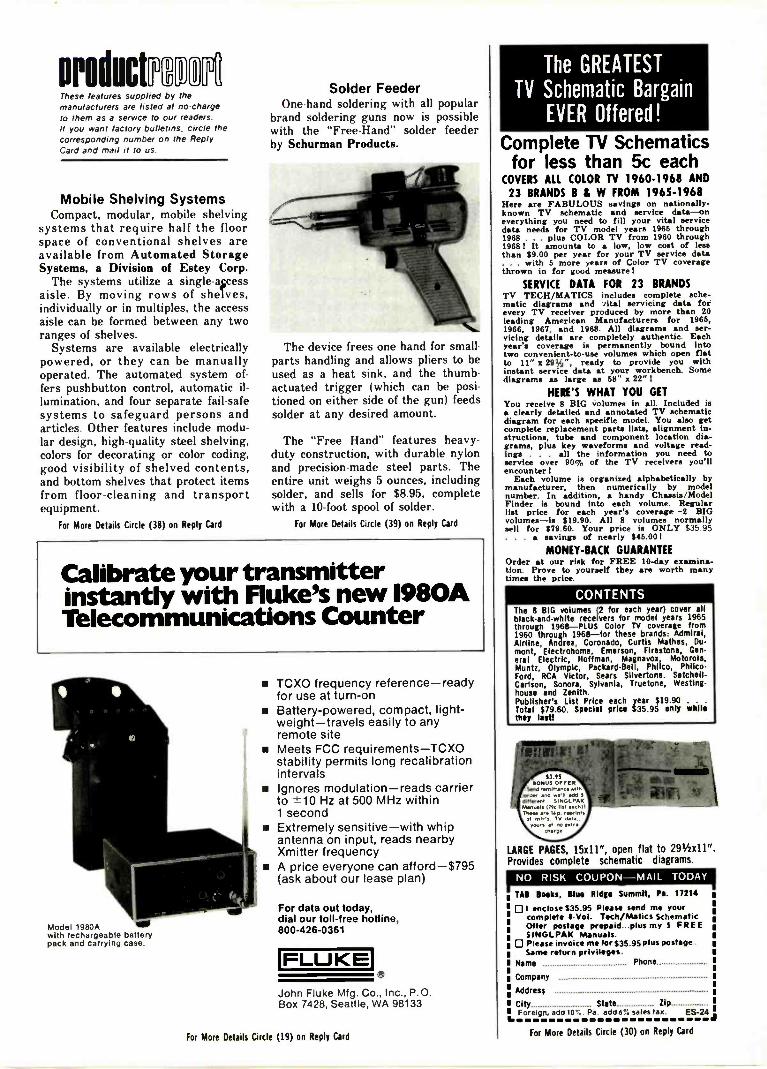
productl'
These features supplied by themanufacturers are listed at no -chargeto them as a service to our readersIf you want factory bulletins, circle thecorresponding number on the ReplyCard and mail it to us
Mobile Shelving SystemsCompact, modular, mobile shelving
systems that require half the floorspace of conventional shelves areavailable from Automated StorageSystems, a Division of Estey Corp.
The systems utilize a single -accessaisle. By moving rows of shelves,individually or in multiples, the accessaisle can be formed between any tworanges of shelves.
Systems are available electricallypowered, or they can be manuallyoperated. The automated system of-fers pushbutton control, automatic il-lumination, and four separate fail-safesystems to safeguard persons andarticles. Other features include modu-lar design, high -quality steel shelving,colors for decorating or color coding,good visibility of shelved contents,and bottom shelves that protect itemsfrom floor -cleaning and transportequipment.
For More Details Circle (38) on Reply Card
Solder FeederOne -hand soldering with all popular
brand soldering guns now is possiblewith the "Free -Hand" solder feederby Schurman Products.
The device frees one hand for small -parts handling and allows pliers to beused as a heat sink, and the thumb -actuated trigger (which can be posi-tioned on either side of the gun) feedssolder at any desired amount.
The "Free Hand" features heavy-duty construction, with durable nylonand precision -made steel parts. Theentire unit weighs 5 ounces, includingsolder, and sells for $8.95, completewith a 10 -foot spool of solder.
For More Details Circle (39) on Reply Card
Calibrate your transmitterinstantly with Fluke's new1980ATelecommunications Counter
Model 1980A 111.with rechargeable batterypack and carrying case
TCXO frequency reference-readyfor use at turn -on
s Battery -powered, compact, light-weight-travels easily to anyremote site
Meets FCC requirements-TCXOstability permits long recalibrationintervals
Ignores modulation-reads carrierto ±10 Hz at 500 MHz within1 second
Extremely sensitive-with whipantenna on input, reads nearbyXmitter frequency
A price everyone can afford-$795(ask about our lease plan)
For data out today,dial our toll -free hotline,800-426-0361
FLUKEJohn Fluke Mfg. Co., Inc., P.O.Box 7428, Seattle, WA 98133
For More Details Circle (19) on Reply Card
The GREATEST
TV Schematic BargainEVER Offered !
Complete TV Schematicsfor less than 5c each
COVERS ALL COLOR TV 1960-1968 AND23 BRANDS B & W FROM 1965-1968
Here are FABULOUS savings on nationally -known TV schematic and service data -oneverything you need to fill your vital servicedata needs for TV model years 1965 through1968. . . plus COLOR TV from 1960 through1968 1 It amounts to a low, low cost of lessthan $9.00 per year for your TV service data. . with 6 more years of Color TV coveragethrown in for good measure!
SERVICE DATA FOR 23 BRANDSTV TECH/MATICS includes complete sche-matic diagrams and 7ital servicing data forevery TV receiver produced by more than 20leading American Manufacturers for 1966,1966, 1967, and 1968. All diagrams and ser-vicing details are completely authentic. Eachyear's coverage is permanently bound intotwo convenient -to -use volumes which open flatto 11" x 29V4", ready to provide you withinstant service data at your workbench. Somediagrams as large as 58" x 22" I
HERE'S WHAT YOU GETYou receive 8 BIG volumes in all. Included isa clearly detailed and annotated TV schematicdiagram for each specific model. You also getcomplete replacement parts lista, alignment in-structions, tube and component location dia-grams, plus key waveforms and voltage read-ings . . . all the information you need toservice over 90% of the TV receivers you'llencounter!
Each volume is organised alphabetically bymanufacturer, then numerically by modelnumber. In addition, a handy Chassis/ModelFinder is bound into each volume. Regularlist price for each year's coverage -2 BIGvolumes-is $19.90. All 8 volumes normallysell for $79.60. Your price is ONLY $35 95. . . a savings of nearly $46.001
MONEY -BACK GUARANTEEOrder at our risk for FREE 10 -day examina-tion. Prove to yourself they are worth manytimes the price.
CONTENTSThe 8 BIG volumes (2 for each year) cover allblack -and -white receivers for model years 1965through 1966-PLUS Color TV coverage from1960 through 1968-for these brands: Admiral,Airline, Andrea, Coronado, Curtis Mathes, Du-mont, Electrohome, Emerson, Firestone, Gen-eral Electric, Hoffman, Magnavox, Motorola,Muntz, Olympic, Packard -Bell, Philco, Philco-Ford, RCA Victor, Sears Slivertone. Satchel!.Carlson, Sonora, Sylvania, Truetone, Westing-house and Zenith.Publisher's List Price each year $19.90 . . .
Total $79.60. Special price 535.95 may whilethey last!
$3.11@ONUS Orris
Send remittance withorder end well adddifferent SINGLPAK/Massie Irk list each)!These we I.V. reprints
mleg TV dateyaws et IN Cdr
chord*
LARGE PAGES, 15x11", open flat to 291/2)(11".Provides complete schematic diagrams.
NO RISK COUPON-MAIL TODAYse s, 81 us Ridge Summit, Pa. 17214
0 I enclose $35.95 Please send me yourcomplete 11 -Vol. Tech/Matics SchematicOffer postage prepaid plus my S FREESINGLPAK Manuals.
P Please invoice me for $35.05 plus postageSame return privileges.
Name Phone
Company
Address
City State ZipForeign, add 10%. Pa. add 6% sales tax. ES -24,
For More Details Circle (30) on Reply Card
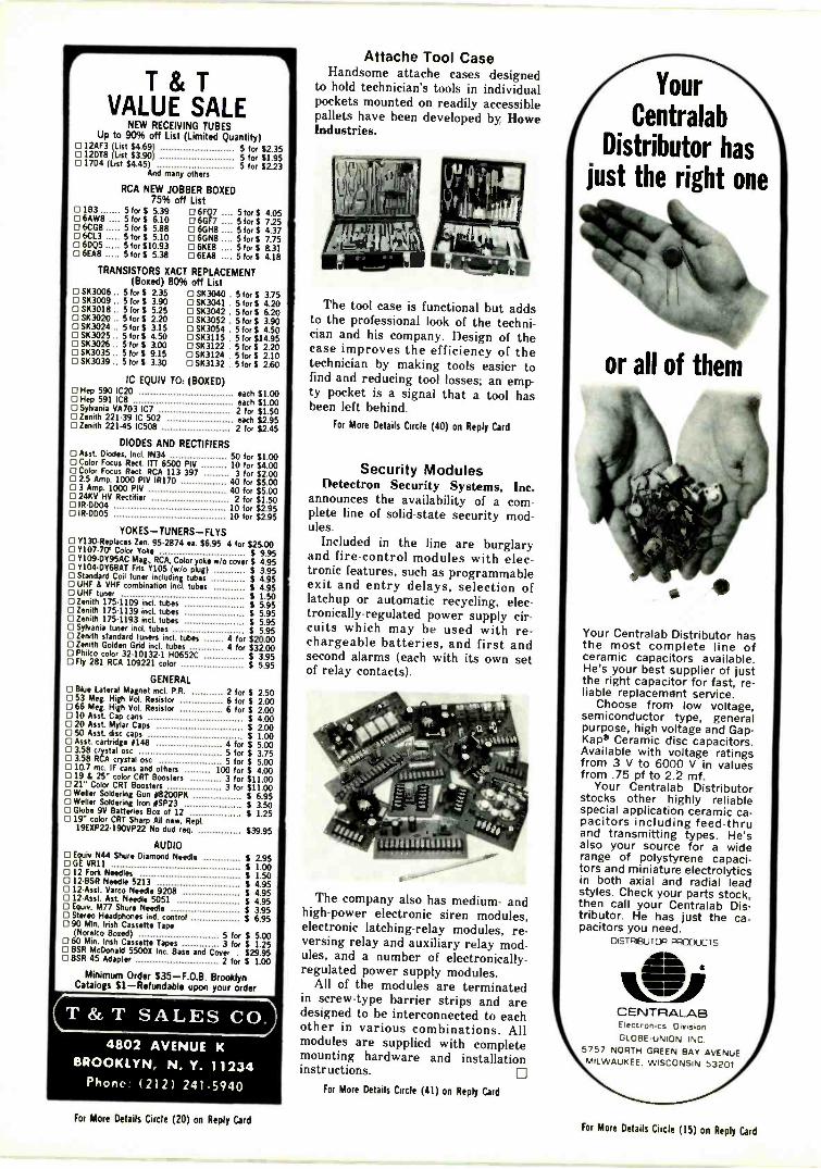
T & TVALUE SALE
NEW RECEIVING TUBESUp to 90% off List (Limited Quantity)
I2AF3 (List $4.69) 5 for $2.3512DT8 (List $3.90) 5 for $1.95
0 1704 (List $4.45) 5 for $2.23And many others
RCA NEW JOBBER BOXED75% off List
o 183 5 for $ 5.39 0 6FQ7 5 for $ 4.056AW8 5for$ 6.10 0 60F7 .... 5 for $ 7.25 6C(111 5 for $ 5.88 6GH8 .... 5 for $ 4.37] 6CL3 5 for $ 5.10 0 6GN8 .... 5 for $ 7.75
60Q5 5 for $10.93 6KE8 .... 5 for $ 8.316EA8 5 for 5.38 6E/48 .... 5 for $ 4.18
TRANSISTORS XACT REPLACEMENT(Boxed) 80% off List
SK3006 .. 5 for $ 2.35SK3009 .. 5 for $ 3.900 SK3018 .. 5 for $ 525
SK3020 .. 5 fors 220[7 SK3024 .. 5 for $ 3.15'7 SK3025 .. 5 fors 4.507 SK3026 .. 5 for $ 3.00
[ SK3035 .. 5 for $ 9.1517 SK3039 $ 3.30
O SK3040 . SK3041 . SK3042 .0 SK3052 .O SK3054 . SK3115 . SK3122 . SK3I24 . SK3I32 .
5 for $ 3.755 for $ 4.205 for $ 6.205 for $ 3.905 for $ 4.505 for $14.955 for $ 2.205for$ 2.105 for $ 2.60
IC EQUIV TO: (BOXED) Hop 590 IC20 each $1.00[7 Hop 591 IC8 each $1.000 Sylvania VA703 IC7 2 for $1.50[7 Zenith 221.39 IC 502 each $2.95[ 3 Zenith 22145 IC508 2 for $2.45
DIODES AND RECTIFIERS Asst. Diodes, Inc! IN34 50 for $1.00n Color Focus Rect. ITT 6500 PIV 10 for $4.00ri Color Focus Rect. RCA 113 397 3 for $2.00 2.5 Amp. 1000 PIV IR170 40 for $5.00[7 3 Amp. 1000 PIV 40 for $5.00 24KV HV Rectifier 2 for $1.50 IR-DD04 10 for $2.95[71R-0005 10 for $2.95
YOKES-TUNERS-FLYS Y130 -Replaces Zen. 95-2874 ea. $6.95 4 for $25.0001'107-70' Color Yoke $ 9.95 1.109-DY95AC Mag., RCA, Color yok w/o cover $ 4.950 Y104.DY68AT Fits Y105 (w/o plug) $ 3.95 Standard Coil tuner including tubes $ 4.950 UHF 8 VHF combination incl. tubes $ 4.95 UHF tuner $ 1.50 Zenith 175-1109 incl. tubes $ 5.95°Zenith 175-1139 incl. tubes $ 5.95°Zenith 175-1193 incL tubes $ 5.95 Sylvania tuner incl. tubes $ 5.95 Zenith standard tuners incl. tubes 4 for $20.000 Zenith Golden Grid incL tubes 4 for $32.00 Phiko color 32-10132.1 H0652C $ 3.950 Fly 281 RCA 109221 color $ 5.95
GENERAL Blue Lateral Magnet incl. P.R. 2 for $ 2.50E3 53 Meg. High Vol. Resistor 6 for $ 2.000 66 Meg. High Vol. Resistor 6 for $ 2.00 10 Asst Cap cans $ 4.00 20 Asst Mylar Caps $ 2.00 50 Asst disc caps $ 1.000 Asst. cartridge 0148 4 for $ 5.000 338 crystal osc 5 for $ 3.750 3.58 RCA crystal osc 5 for $ 5.00 10.7 mc. IF cans and others 100 for $ 4.00 19 14 25" color CRT Boosters 3 for $11.000 21" Color CRT Boosters 3 for $11.000 Weller Soldering Gun .8200PK $ 6.950 Weller Soldering Iron OSP23 $ 3.500 Glob* 9V Batteries Box of 12 $ 1.250 19" color CRT Sharp All new. Rept
19EXP22490VP22 No dud req. $39.95
AUDIO Equiv N44 Shure Diamond Needle $ 2.950 GE VR11 $ 1.000 12 Fork Needles $ 1.50 12-BSR Needle 5213 $ 4.95 12 -Asst. Varco Needle 9208 $ 4.950 12 -Asst Ast Needle 5051 $ 4.950 Equiv. M77 Shure Needle $ 3.950 Stereo Headphones incl. control $ 6.95 90 Min. Irish Cassette Tape
(Norelco Boned) 5 for $ 5.000 60 Min. Irish Cassette Tapes 3 for $ 1.250 BSR McDonald 5500X Inc. Base and Cover
. $29.95 BSR 45 Adapter 2 for $ 1.00
Minimum Order S35-F.O.B. BrooklynCatalogs 81 -Refundable upon your order
MP dl
T & T SALES CO.4802 AVENUE K
BROOKLYN, N. Y. 11234Phone (212) 241-5940
Attache Tool CaseHandsome attache cases designed
to hold technician's tools in individualpockets mounted on readily accessiblepallets have been developed by HoweIndustries.
The tool case is functional but addsto the professional look of the techni-cian and his company. Design of thecase improves the efficiency of thetechnician by making tools easier tofind and reducing tool losses; an emp-ty pocket is a signal that a tool hasbeen left behind.
For More Details Circle (40) on Reply Card
Security ModulesDetectron Security Systems, Inc.
announces the availability of a com-plete line of solid-state security mod-ules.
Included in the line are burglaryand fire -control modules with elec-tronic features, such as programmableexit and entry delays, selection oflatchup or automatic recycling, elec-tronically -regulated power supply cir-cuits which may be used with re-chargeable batteries, and first andsecond alarms (each with its own setof relay contacts).
I -
The company also has medium- andhigh -power electronic siren modules,electronic latching -relay modules, re-versing relay and auxiliary relay mod-ules, and a number of electronically -
regulated power supply modules.All of the modules are terminated
in screw -type barrier strips and aredesigned to be interconnected to eachother in various combinations. Allmodules are supplied with completemounting hardware and installationinstructions.
For More Details Circle (41) on Reply Card
Your
CentralabDistributor has
just the right one
k4w(\,,
or all of them
Your Centralab Distributor hasthe most complete line ofceramic capacitors available.He's your best supplier of justthe right capacitor for fast, re-liable replacement service.
Choose from low voltage,semiconductor type, generalpurpose, high voltage and Gap-Kap* Ceramic disc capacitors.Available with voltage ratingsfrom 3 V to 6000 V in valuesfrom .75 pf to 2.2 mf.
Your Centralab Distributorstocks other highly reliablespecial application ceramic ca-pacitors including feed-thruand transmitting types. He'salso your source for a widerange of polystyrene capaci-tors and miniature electrolyticsin both axial and radial leadstyles. Check your parts stock,then call your Centralab Dis-tributor. He has just the ca-pacitors you need.
DISTREUTOR PAM' ('TS
CENTRALABElectronics DivisionGLOBE -UNION INC
5757 NORTH GREEN BAY AVENUEMILWAUKEE. WISCONSIN 53201
For More Details Circle (20) on Reply CardFor More Details Circle (15) on Reply Card
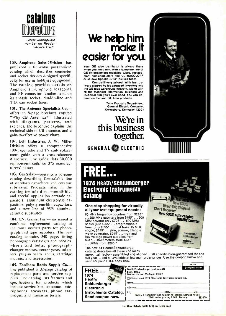
catalogs
Circ e appropriatenumber on Reader
Service Card
100. Amphenol Sales Division-haspublished a full -color pocket -sizedcatalog which describes connectorand socket devices designed specifi-cally for use in hobbyist equipment.The catalog provides details onAmphenol's microphone, hexagonal,and RF connector families, and onits chassis socket, dual -in -line andT.O. can socket lines.
101. The Antenna Specialists Co.-otters an 8 -page brochure entitled"Why CB Antennas?". Illustratedwith diagrams, patterns, andsketches, the brochure explains thetechnical side of CB antennas and again -to -effective power chart.
102. Bell Industries, J. W. MillerDivision-offers a comprehensive100 -page radio and TV coil -replace-ment guide with a cross-referencedirectory. The guide lists 30,000replacement coils for 375 manufac-turers' names.
103. Centralab-presents a 36 -pagecatalog describing Centralab's lineof standard capacitors and ceramicsubstrates. Products listed in thecatalog include disc, monolithic,and special application ceramic ca-pacitors, aluminum electrolytic ca-pacitors, polystyrene -film capacitors,and a new line of 95% alumina -ceramic substrates.
104. EV. Game, Inc.-has issued acombined replacement catalog ofthe most needed parts for phono-graph and tape recorders. The newcatalog contains 240 pages listingphonograph cartridges and needles,wheels and belts, phonograph -changer motors, center -posts, adap-ters, plug-in heads, shells, cartridgemounts, and accessories.
105. Fordham Radio Supply Co.-has published a 32 -page catalog ofreplacement parts and service sup-plies. The catalog lists features andspecifications for products whichinclude service kits, antennas, mic-rophones, speakers, phono car-tridges, and transistor testers.
We her ake it1p
him
easier for you.Your GE tube distributor is always therewhen you need him. With a complete line ofGE entertainment receiving tubes, replace-ment semiconductors and ULTRACOLOR'or all -new Spectra -Brits" picture tubes.
Competitively priced. With fast de-livery assured by his balanced inventory andthe GE tube warehouse network. Along withall the technical information, business andtechnical aids you'll ever need. You can de-pend on him and GE tube products.
Tube Products Department.General Electric Company,
Owensboro, Kentucky 42301
We're inthis business
together.GENERAL ELECTRIC
FREE...1974 Heath/SchlumbergerElectronic InstrumentsCatalog
One -stop shopping for virtuallyall your test equipment needs:80 MHz frequency counters from $295'
. 200 MHz counters from $495' ... 600MHz counter only $795' ... 600 MHzscaler just $365' ... programmabletimer only $395' ...dual trace 15 MHzscope, $595' ...sine, square, trianglewave generator, $245' ... high andlow voltage power supplies from$34' multimeters from $65*...DVMs from $285.'The new 74 Heath/Schlumbergercatalog describes all these and manymore...all factory assembled and aligned...all specification -guaranteed for onefull year...and all available at low mail-order prices. Use the coupon below andsend for your FREE copy now.
-2 49fa*
tau*
r
FREE...1974Heath/SchlumbergerElectronicInstruments Catalog.Send coupon now.
t° tiV -10N llS
eChart Retorter 44170S.
rangingd
110MHz Counter
Heath/Schlumberger InstrumentsDept. 196-2Benton Harbor, Michigan 49022
['Please send 1974 Electronic Instuments Catalog.
Name
Address
City State lipPrices & specifications subject to change without notice.
'Mail order prices; F.0.8 factory. EM. -409
!tom Heath/.ctilumberger
MEATH
For More Details Circle (21) on Reply Card
SPRAYAWAY
THERACKET.
4111111air001 401
LUBA' -CLEANER
9
br,dt 1.1,10 hoa141,00,
.0 sumo
Squeak. Whine.Whirr. Psss! Silence.Quietrole did itagain. Silencedthose moving.T.V.parts, with onesquirt from thehandy spray pack.Cleaned away dirt,dust, and crud.Without damaginganything ... in anyblack and white orcolor set. Silence isQolden. So is
uietrole.
Also available inbottles, and thenew Silicone-"Silitron."
Product of
QUIETROLECOMPANY
* Spartanburg, South Carolina
For More Details Circle (22) on Reply Card
BRAND NEW FROM ENDECO
the solderingiron with alight
Exclusive new safety lightshows when power is on
MODEL 540S 510.95 NET
Two heats -20w and 40w-to handle any job On -off switch Cool, unbreakable polycar-bonate handle Ironclad tips for longer life Burn -resistant neoprene cord 81/2" long,2 oz Converts to a desoldering iron withlow cost attachment Also desoldering ironsand soldering/desoldering kits.
See your distributor or write .
ec
5127 EAST 65TH ST.INDIANAPOLIS,INDIANA 46220PHONE 317 251 1231
enterprisedevelopmentcorporation
(Continued from previous page)
106. Heath/Schlumberger Instru-ments-has published a catalogwhich provides descriptions, photos,and specifications for instrumentssuch as frequency recorders, oscillo-scopes, power supplies, digital mul-timeters, recorder systems, an ana-log-digital teaching system and theHeath/Malmstadt-Enke Lab Sta-tions. Featured in the catalog is thenew line of autoranging frequencycounters and a low-cost strip -chartrecorder. 0
Those TV "Dogs"(Continued from page 33)
But, suppose the 6JHS fails todraw any current. Diodes X26 andX28 become open circuits, there isno voltage at the 6JHS cathode, andno positive voltage can flow throughR192. At the same time, the nega-tive voltage from R193 continues,and, without the cancelling effect ofthe positive voltage, drives the gridof the 6LB6 more negative thanusual. This reduces the maximumplate current, lowers the high volt-age and narrows the picture width.
Two things are accomplished.The high voltage is reduced, sothere is no X-ray danger, and thepicture is poor which encouragesthe set owner to call a technicianfor needed repairs.
One interesting side effect hap-pens when the HV regulator is notoperating. Brightness, width andfocus all become noticeably betteras the brightness level is increased,although they don't ever becomenormal.
Now, back to testing the high-
voltage regulator circuit. It can bemade ineffective for testing pur-
FREE CATALOGHARD -TO -FIND PRECISION TOOLS
Lists more than 1700 items-pliers,tweezers, wire strippers, vacuum systems,relay tools, optical equipment, tool kitsand cases. Also includes four pages ofuseful "Tool Tips" to aid in tool selection.
t'VE s rsT TOOLS4117 N. 4411, Street, theca, Aris Malt
For More Details Circle (24) on Reply Card
OWN YOUR OWN PIC Tu REtu BE REBUILDING BUSINESS
Wnn aikeStde InOusinesbuild.ng equipment you canrebuild any picture tube'
For complete details sendname address tip code toLAKESIDE INDUSTRIES3520 VS Fulertim Aft.Chicago. III. 00047Khans 312-34243U
.1
1, IL
poses by removing the tube fromthe socket, or by grounding thecontrol grid. However, that wouldactivate the fail-safe circuit andvoid the purpose of the test.
It is necessary to short acrossX26 and X28 using a test lead, plusremoving the regulator tube inorder to kill the regulation.
In this case, the symptoms on thescreen were gone, and the highvoltage was excessive (naturally).
VDR's are difficult to test ac-curately, so again I chose the easyway by replacing R178, and reset-ting the high voltage. No moredisplaced lines or trapezoidalpictures on the screen after that.
ConclusionsThese excerpts from my Case-
book are all actual examples of theservicing philosophy I use and ad-vise others to adopt. First, knowwhich basic circuits are capable ofcausing which symptoms. Then testthose circuits in the fastest waypossible. In most instances, thismeans checking the entire circuit asthough it had only one stage. Thenzero in on the one bad stage thatcontains the defect.
Wholesale parts replacementsand replacement because of sus-picion alone are minimized by thismethod of testing. 0
Medical Electronics(Continued from page 19)
any valid reason, but that are en-forced with an iron hand by thestrong-willed nurses who run theOR. This is not as tyrannical as itsounds, for the infection rate of anyOR seems to be in direct propor-tion to the observance of thoserules. If you are told to do some-thing in a certain way, do it!
In most areas of the hospital, thesecurity people will probably wantyou to wear a name badge or awhite "lab coat" so the patients cansee at a glance you belong.
Regardless of the "dress code",you will be required to do yourservicing of the equipment accu-rately, rapidly, and with excellentcraftsmanship. After all, humanlives sometimes depend on yourworkmanship; and that's a lot moreimportant than the disappointmentof a viewer who can't see theSunday afternoon football game! 0
For More Details Circle (23) on Reply Card
56 ELECTRONIC SERVICING/February, 1974For More Details Circle (25) on Reply Card
phalli!' TNPHOTOFACT BULLETIN lists new PHOTOFACT coverage
issued during the last month for new TV chassis.
CATALINA122-4346B, 122-4349A, 122-4356A, 122-4359A 1379-1
CORONADOTV2-2034A, TV2-2034B 1378-1
DUMONT16DP40, 16DP41WR (Ch. T32K10-1 A) 1373-'
J. C. PENNEY4863A, 4864A, 4897A,4922A, 4923A, 6898A 1375-1
MGABB -093, BB -094 1374-1
MGABB -126, BS -125 1376-1
MIDLAND15-013 1377-1
OLYMPICCT -518 1372-1
PANASONICCT -26, CT -27 1371-1
PANASONICCT -772 1373-2
PANASONICCT -911 (Ch. ETA -3) 1379-2
RCAChassis CTC59XD/XE/XF 1376-2Remote Control Receiver, TransmitterCRK18A 1376-2-A
RCAChassis CTC68A/AEIAFIH/P 1378-2Remote Control Receiver CTP22A,Transmitter CRK19A 1378-2-A
RCAFS450W (Ch. CTC66XA) 1372-2
RCAChassis KCS171XC/ XE 1371-2Remote Control Receiver,Transmitter KRT5D 1371-2-A
RCAChassis KCS190B/C 1373-3
SEARS562.50170300, 562.50721200 1374-3
SEARS564.50390200/0201 /1300 1379-3
TOSHIBAC501S (Ch. TAC-6410) 1377-2
4 Money -saving reasonsto buy EICO's Solid StateTest Equipment.
330!kirr
242 379 -441tri
iO
0
TR-410
EICO 242 FET-TVOM. Peak -to -peak
measurements of AC volts and milli -amps. 61/2" meter. 7 non -skip ranges.High input impedance. Low 1 voltscale. DC/AC Multi -Probe. AC or bat-tery operated. Kit $84.95, Wired$119.95
EICO 330 RF Signal Generator. 5 bandscover a range from 100 kHz to 54 MHz.Calibrated modulation adjustment con-trol. 400 Hz audio output. Provisionfor modulating RF with internal orexternal signal source. Kit $69.95,Wired $109.95
EICO 379 Sloe/Square Wave Genera-tor. Simultaneous sine and square waveoutputs. Covers 20 Hz to MHz In fiveranges. Low distortion sultzer feed-back circuit. Square wave rise timebetter than 0.1 microseconds. Klt
$79.95 , Wired $119.95
EICO TR-410 Triggered Sweep Scope.100% solid state. DC to 10MHz band-width. Sweep synchronized pate out-put. Z -Axis Input. Use as vectorscopefor color TV servicing. One probe fordirect and 10:1 measurements. Wired$429.95.
FREE 32 PAGE EICO CATALOGFor latest catalog on Elco Solid State Test Equipment, Automotiveand Hobby Electronics, Burglar -Fire Alarm Systems, Mere°, andname of nearest EICO Distributor, check reader service card orsend 25e for fast first class mall service.
EICO, 283 Malta Street, Brooklyn, N.Y. 11207 EICO1-7
18°
WorkingArc
POSTPAID
For More Details Circle (26) on Reply Card
Midget RATCHET SETplus ADAPTERS
Seventeen different interchangeable adapt-ers with a screwdriver attachment andextension, plus the world's mightiestMIDGET RATCHET in a compact 4" x 6"steel case. The strength of this twentytooth stainless steel ratchet far exceedstorque standards set by military specifi-cations. Requiring only an 18° workingarc, reverse action is obtained by simplyturning the ratchet over. Kit includes 12Allen Hex Adapters from .050" to 3fe.".2 popular Philips sizes (#1 and #21, 2Slotted Head sizes (1/1" and Yi"), plus a14" Square Drive for use with standardsockets.
Only $12.95Send Check
or Money Order
POCKET SIZENO. 6320 KIT
Send Check THE CHAPMAN MANUFACTURING COMPANYor Money Order to DURHAM, CONNECTICUT 06422 Dept. ES -2
For More Details Circle (27) on Reply Card

The MARKETPLACEadvertisers' °
This classified section is availableto electronic technicians and ownersor managers of service shops whohave for sale surplus supplies andequipment or who are seekingemployment or recruiting employees.
Advertising Ratesin the ClassifiedSection are:
25 cents per word(minimum $3.00)
"Blind" ads $2.00additional
All letters capitalized35 cents per word
Each ad insertion must be accompa-nied by a check for the full cost ofthe ad.
Deadline for acceptance is 30 daysprior to the date of the issue in whichthe ad is to be published.
This classified section is not opento the regular paid product advertis-ing of manufacturers.
FOR SALE
TV & RADIO TUBES 36c EA!! Free colorcatalog. Cornell. 4221 University. San Diego, Cal-ifornia 92105. 2-74-61
USE YOUR SCOPE (ANY MODEL. NO REWIR-ING) TO TEST TRANSISTOR IN/OUT CIR-CUIT. SIMPLE ISTRUCTIONS $1.00. SCHEKTECHNICAL SERVICES. 8101 SCHRIDER ST..SILVER SPRING. MARYLAND 20910. 10-73-12
UNUSUAL SURPLUS AND PARTS Catalog. SI.ETCO Electronics Dept. E.S.. Box 741. Montreal"A" H3C 2V2 12-73-12t
BUILD YOUR OWN 12 volt power supply for V3cost. Operates CB Radio and auto tape player inhome. Great for charging car battery. too! Simplestep by step instructions. SI. TIPS. Box 188.Bruce. Miss. 38915. 2-74-1t
HELP WANTED
TIRED OF THE HASSLE AND LONG HOURSOF RUNNING YOUR OWN BUSINESS'. Con-sider relocating to warm. sunny Florida with year'round swimming. boating and fishing AND asecure job with excellent pay. benefits and growthpotential. We desperately need good TV repairmenfor both bench and outside work. Please sendresume and salary requirements to: HOLLY-WOOD TV. 315 South 21st Ave.. Hollywood.Florida. 33020. Phone 305-925-71'9. 2-74-1t
EDUCATION INSTRUCTION
REPAIR TV TUNERS-High Earnings: CompleteCourse Details. 12 Repair Tricks. Many Plans.Two Lessons, all for Sl. Refundable. Frank Bocek.Box 3236 Enterprise. Redding. Calif. 96001. 9-73-7t
B & K Div., Dynascan Corp. 7
Blonder Tongue Laboratories, Inc...51Bussmann Mfg. Div.,
McGraw Edison 27
Castle TV Tuner Service Cover 3Centralab Globe -Union, Inc 54Channel Master 20-21Chapman Manufacturing 57
Edsyn, Inc. 40Eico Electronic Instrument Co 57Enterprise Development Corp 56
Fluke 53
GC Electronics 40General Electric Company 13,55
Heath Company 43Heath/Schlumberger Instruments 55
International Components Corp 52
Jensen Tools and Alloys 56
Lakeside Industries 56Lectrotech, Inc. 43Littelfuse, Inc. Cover 4
Mallory Distributor Products 35
Panasonic Parts Division 37Precision Tuner Service Cover 2
Quietrole Company 56
RCA Electronic Components 9
H. K. Simon Company, Inc. 3
Sprague Products Company 11
GTE Sylvania - Consumer Renewal ..1
T & T Sales Company 54TV Tech Aid 52Tab Books 53
5Tuner Service Corporation
Winegard Company 29
GET COMPLETEDETAILS
about the productsadvertised or described
in this issue.
Use FreeReader Service Card.
Be sure to include
your name and address
Wanted!700,000.
busy executiveswho can:
If you can spend some time,even a few hours, with someonewho needs a hand, not a handout,call your local Voluntary ActionCenter. Or write to "Volunteer,'Washington, D.C. 20013.
We need you.c9The National Center for
Voluntary Action.
advertising contributed for the public good
58 ELECTRONIC SERVICING/February, 1974

NEN/ AC BATTERY POWERED SUM&
Latest, all solid state version of the sensational signal circuit analyzing timesaveroriginated by Castle.Invaluable for locating the break in the tuner and i.f. signal chain or analyzing agc system de-fects in tube TV receivers . . . essential for speedy location of signal circuit defects in modular IC,solid state and hybrid TV receivers.
A NEW APPROACH to agc system analyzing!Permits signal injection after the agc controlled stages to simplify testing for agc defects.
Works with any 40MHz receiver . color or black and white .. solid state, tube or hybrid High level, low impedonce output furnishes signal usable at input of final i.f. stage. Special output circuit works equally well into first i.f. input of late model, link coupled systems and older, low "C"
bondposs coupled systems. Antenna input and i.f. output electrically isolated; no -hot- chassis hazards No need to disconnect supply leads from suspected tuner being tested. Substitutes the VHF tuner and tests the UHF
tuner.
Tunes all 12 VHF channels, hos preset (memory) fine tuning on all channels Higher overall gain than previous models with wide range gain reduction control of 60db. Completely self contained and battery operated, uses popular batteries avoilable everywhere. Simple battery
replacement, battery compartment in rear of custom molded case. Reduced current consumption extends battery life to as much as double that of previous models. Bright 110
indicator warns when unit is ON. Use on the bench or in the home ... onywhere. Comes complete with extension cables, batteries and instructions.
Spoc I I ketkons
Inputs, )00 phr. balanced VU? antenna terminals, lectrIcall,7.ate..4 coln 40 MI. empl111. ICR.11 RCA Rho. 'Ack
Se .1.6114 )0 microvotte.Input signal hendlIng cmasbillty: now 100,000 rnlcrovolts,
Output -.40 ist/la TV 1.1bandworthh 6 Malt..-14410fenatc... output ctrcult sr. Schad cableto furnish useble mgnal for all Input cites..Termination is aCe Orono jack, lectrIcIly Isolatcl.
Tuning Rama.
Tuning.
Gt.. Canto,
Power supply,
MI 11 VHF TV channels. plus Ch. el 40 MHz 1.1111111 on'4141oh for testing UHT tu. High sbil., of 40 Ma.mnpbfier termite two 05.1Vner. Subbase to Mt cascaded lc.high level 40 MHz oustx signal boat ny VHt clunnal.
In.., memory) fine tuning.
Gain reduction 60 do.
It vette. Use@ two Sv transistor batterte.
Site 6 Weight 6.5 6.5 3.15' ear lustve of control Snobs sour handle.1.5 lbs complete with batteries.
Accessories: -Mattermatchcoupler output cble with RCA phorto lack
"Meattornalchcoupler- outfox cable with Illgette clip Mr-ntInalloem.l/Hr tuner test cable.
TV TUNER SOBER. Mark IP (Battery model )
Contact your distributor.
net $45.95
TV TUNER SOBER Mark IP-A (120 WIC * Battery model) net >554.95All battery only models of the SUBBER may be factory modified for 120VAC use.Contact your distributor for details and cost.
CASTLE TV TUNER SERVICE, INC.5701 N. Western Ave., Chicago, Illinois 60645 mon.: (312) - 561-6354
In Canada: Len Finkler Co., Ontario
For More Details Circle (2) on Reply Card
24hourwatch
Everyday. All over the world. On millions of 24 hour watch. All over the world. It's a bigtelevision sets, our sentry stands. The new assignment. But the Littelfuse Sentry is one ofLittelfuse Circuit Breaker. Meeting industry's television's brightest stars.new safety requirements of SE -O insulatingmaterials, our breaker is demanded by virtuallyall set manufacturers. It's the perfect replace-ment part too!
Contact your nearest Littelfuse source. He'llshow you the 19 available models with a varietyof packaging choices.
1PUS"Littelfuse, Inc. Subsidiary of Tracor, Inc.800 E. Northwest Highway, Des Plaines, III. 60016
For More Details Circle (3) on Reply Card