11.11
14
Storm Drainage Systems 11.11-1 December 2003 ConnDOT Drainage Manual 11.11 Storm Drains 11.11.1 Introduction After the preliminary locations of inlets, connecting pipes and outfalls with tailwaters have been determined, the next logical step is the computation of the rate of discharge to be carried by each reach of the storm drain, and the determination of the size and gradient of pipe required to convey this discharge. This is done by starting at the upstream reach, calculating the discharge and sizing the pipe, then proceeding downstream, reach by reach to the point where the storm drain connects with other drains or the outfall. For manholes where the pipe size is increased, the downstream crown should be lower than the upstream crown by the amount of the energy loss in the manhole. The rate of discharge at any point in the storm drain is not necessarily the sum of the inlet flow rates of all inlets above that section of storm drain. It is generally less than this total. The time of concentration is most influential and as the time of concentration grows larger, the rainfall intensity to be used in the design grows smaller. In some cases, where a relatively large drainage area with a short time of concentration is added to the system, the peak flow may be larger using the shorter time even though the entire drainage area is not contributing. The prudent designer will be alert for unusual conditions and determine which time of concentration controls for each pipe segment. See Section 11.5.5 for a discussion on time of concentration. For ordinary conditions, storm drains should be sized on the assumption that they will flow full or practically full under the design discharge but will not flow under pressure head. The Manning's formula is recommended for capacity calculations. In locations such as depressed roadway sections and underpasses where ponded water can be removed only through the storm drain system, a higher design frequency should be analyzed to ensure the roadway stays open to traffic (see Table 11-2 for design criteria). The main storm drain downstream of the depressed section should be designed by computing the hydraulic grade line and keeping the water surface elevations below the grates and/or established critical elevations for the check storm. 11.11.2 General Guidelines The following items must be considered during the design of a storm drain system. • Storm drains shall be designed for "just-full" condition. The head waters in structures shall be limited to 0.3 meters (1 ft) below the top of grate, taking into consideration the possible effect of headwater in the next downstream structure. • Underdrain pipes of 100 and 150 mm (4 in and 6 in) size should be laid in straight segments or gradual curves if possible. Where bends of underdrain are necessary to enter a structure they should be no greater than 30 degrees. • Long skew crossings of storm drain laterals under pavement should be avoided. • All roadway drainage, including the side and slope ditches shall be carried to a suitable outlet, preferably an existing stream. Where outletting to an existing stream is impractical, or where no stream is available, appropriate drainage rights must be obtained. • The discharge of effluent from sanitary sewers, cesspools, septic tanks, discharge of cooling water or industrial wastes into a State maintained roadway drainage system will not be permitted. • Private connections to State drainage systems are only allowed after issuance of an encroachment permit accompanied by a special connection agreement.
-
Upload
robert-nixon -
Category
Documents
-
view
18 -
download
3
description
Storm Drainage System
Transcript of 11.11

Storm Drainage Systems 11.11-1
December 2003 ConnDOT Drainage Manual
11.11 Storm Drains
11.11.1 Introduction
After the preliminary locations of inlets, connecting pipes and outfalls with tailwaters have beendetermined, the next logical step is the computation of the rate of discharge to be carried by eachreach of the storm drain, and the determination of the size and gradient of pipe required to conveythis discharge. This is done by starting at the upstream reach, calculating the discharge and sizingthe pipe, then proceeding downstream, reach by reach to the point where the storm drain connectswith other drains or the outfall. For manholes where the pipe size is increased, the downstreamcrown should be lower than the upstream crown by the amount of the energy loss in the manhole.
The rate of discharge at any point in the storm drain is not necessarily the sum of the inlet flowrates of all inlets above that section of storm drain. It is generally less than this total. The time ofconcentration is most influential and as the time of concentration grows larger, the rainfall intensityto be used in the design grows smaller. In some cases, where a relatively large drainage area with ashort time of concentration is added to the system, the peak flow may be larger using the shortertime even though the entire drainage area is not contributing. The prudent designer will be alert forunusual conditions and determine which time of concentration controls for each pipe segment. SeeSection 11.5.5 for a discussion on time of concentration.
For ordinary conditions, storm drains should be sized on the assumption that they will flow fullor practically full under the design discharge but will not flow under pressure head. The Manning'sformula is recommended for capacity calculations. In locations such as depressed roadway sectionsand underpasses where ponded water can be removed only through the storm drain system, a higherdesign frequency should be analyzed to ensure the roadway stays open to traffic (see Table 11-2 fordesign criteria). The main storm drain downstream of the depressed section should be designed bycomputing the hydraulic grade line and keeping the water surface elevations below the grates and/orestablished critical elevations for the check storm.
11.11.2 General Guidelines
The following items must be considered during the design of a storm drain system.
• Storm drains shall be designed for "just-full" condition. The head waters in structures shall belimited to 0.3 meters (1 ft) below the top of grate, taking into consideration the possible effectof headwater in the next downstream structure.
• Underdrain pipes of 100 and 150 mm (4 in and 6 in) size should be laid in straight segmentsor gradual curves if possible. Where bends of underdrain are necessary to enter a structurethey should be no greater than 30 degrees.
• Long skew crossings of storm drain laterals under pavement should be avoided.• All roadway drainage, including the side and slope ditches shall be carried to a suitable outlet,
preferably an existing stream. Where outletting to an existing stream is impractical, or whereno stream is available, appropriate drainage rights must be obtained.
• The discharge of effluent from sanitary sewers, cesspools, septic tanks, discharge of coolingwater or industrial wastes into a State maintained roadway drainage system will not bepermitted.
• Private connections to State drainage systems are only allowed after issuance of anencroachment permit accompanied by a special connection agreement.
11.11-2 Storm Drainage Systems
ConnDOT Drainage Manual October 2000
• Roadway drainage shall not be outletted into existing drainage systems which are privatelyowned or those maintained by towns or cities except in the case where an independent outletis not feasible due to excessive cost or other reasons. Where outletting into such a system, anagreement must be entered into with the municipality. A deeded right to drain must besecured from owners of private systems.
• All existing metal pipes to be abandoned under the travelway are to be removed. Concretepipes to be abandoned should be plugged at the ends.
• State drainage systems shall not be outletted into municipal systems which carry both stormwater and sanitary sewage, nor will any such municipal system carrying both storm water andsanitary sewage be outletted into State systems.
• Diversion of watershed area should be avoided if possible. However, in all cases wheredrainage is diverted from one watershed area to another, as is frequently the case in incisedhighways, the designer shall note the diversions in the computations and on the preliminaryplans to better allow the reviewers and right of way negotiators to make proper provisions forthe lawful disposal of the drainage from this area at the outlet locations.
• Utility conflicts may require design changes. New installations should be kept at least 0.3meters (1 ft) from any utilities.
• The pertinent plans and computations for drainage systems on a project which originate orterminate on an adjacent project shall be furnished for review by the designer of the projectbeing reviewed. The area used for runoff computation shall be shown on topographical mapsalso to be supplied.
• Each outlet must be carefully designed with erosion protection as needed and carried downsteep slopes to lesser slopes where outlet erosion will not occur. Riprap shall be designed atall outlets not flowing over exposed rock or into deep watercourses or ponds. (See Section11.14.)
• Storm drainage systems will be designed for the watershed which naturally drains to it. Inmany urban areas the existing drainage systems are inadequate and it is impossible to provideinlet capacity for the overflow, however, the trunk line system should be designed to allow themunicipality to upgrade their contributing system at a future date.
• Minimum size pipe for storm drainage is 300 mm (12 in).• Slotted drain shall be outletted into catch basins.
11.11.3 Outlets
All proposed storm drains have an outlet point where the flow is discharged. The designer shouldconsider at least the following aspects that may affect the hydraulic design of a storm drainagesystem.
• The flowline elevation of the outfall should be equal to, or higher than the recipient. If this isnot the case, excavation may be required to ensure positive gravity flow, or in severe casespump stations may be required.
• Where practical, the outlet should be positioned in the outfall channel so that it is pointed in adownstream direction. This will reduce turbulence and the potential for erosion.
• When the outlet is located in a manner to allow the discharge to impinge on the opposite bankof a channel, that bank should be evaluated to determine the need for riprap.
Storm Drainage Systems 11.11-3
October 2000 ConnDOT Drainage Manual
11.11.4 Bridge Deck Outlets
The design of deck drain outlets should be such as to prevent the discharge of drainage wateragainst any portion of the structure or on moving traffic below, and to prevent erosion at the outletof the downspout. Deck drainage may be connected to conduits leading to stormwater outfalls atground level. Water in a roadway gutter section should be intercepted prior to the bridge.Scuppers are not to be designed with freefall outlets except over water or where it can bedemonstrated that the flow will not cause damage or become a nuisance.
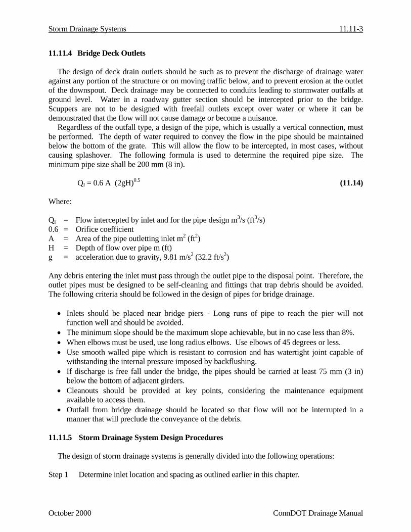
Regardless of the outfall type, a design of the pipe, which is usually a vertical connection, mustbe performed. The depth of water required to convey the flow in the pipe should be maintainedbelow the bottom of the grate. This will allow the flow to be intercepted, in most cases, withoutcausing splashover. The following formula is used to determine the required pipe size. Theminimum pipe size shall be 200 mm (8 in).
QI = 0.6 A (2gH)0.5 (11.14)
Where:
QI = Flow intercepted by inlet and for the pipe design m3/s (ft3/s)0.6 = Orifice coefficientA = Area of the pipe outletting inlet m2 (ft2)H = Depth of flow over pipe m (ft)g = acceleration due to gravity, 9.81 m/s2 (32.2 ft/s2)
Any debris entering the inlet must pass through the outlet pipe to the disposal point. Therefore, theoutlet pipes must be designed to be self-cleaning and fittings that trap debris should be avoided.The following criteria should be followed in the design of pipes for bridge drainage.
• Inlets should be placed near bridge piers - Long runs of pipe to reach the pier will notfunction well and should be avoided.
• The minimum slope should be the maximum slope achievable, but in no case less than 8%.• When elbows must be used, use long radius elbows. Use elbows of 45 degrees or less.• Use smooth walled pipe which is resistant to corrosion and has watertight joint capable of
withstanding the internal pressure imposed by backflushing.• If discharge is free fall under the bridge, the pipes should be carried at least 75 mm (3 in)
below the bottom of adjacent girders.• Cleanouts should be provided at key points, considering the maintenance equipment
available to access them.• Outfall from bridge drainage should be located so that flow will not be interrupted in a
manner that will preclude the conveyance of the debris.
11.11.5 Storm Drainage System Design Procedures
The design of storm drainage systems is generally divided into the following operations:
Step 1 Determine inlet location and spacing as outlined earlier in this chapter.

11.11-4 Storm Drainage Systems
ConnDOT Drainage Manual December 2003
Step 2 Prepare plan layout of the storm drainage system establishing the following design data:a. Location of storm drains.b. Direction of flow.c. Location of manholes.d. Location of existing utilities such as water, gas, sanitary sewer, electric,
communication facilities, etc.
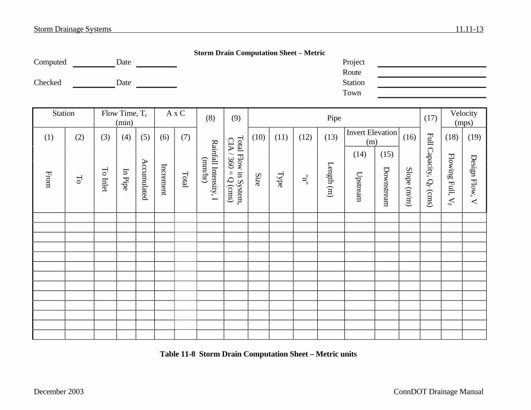
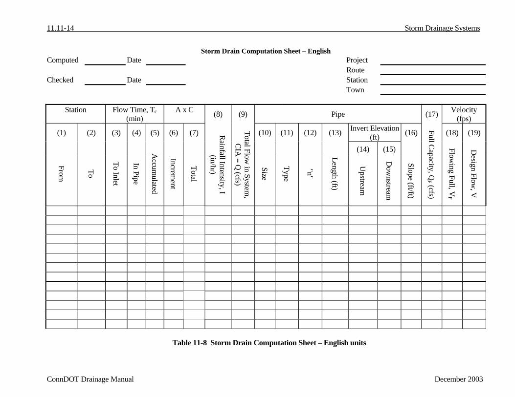
Step 3 Perform storm drainage computations to determine flows in the drainage system and therequired pipe sizes for “just-full conditions” (smallest available pipe size not flowing atfull capacity for the design discharge). Use the Storm Drainage Computation Sheet, Table11-8 or 11-8.1, described below, to facilitate the computational procedure.
• Columns 1 and 2 – Starting at the highest point in the system and proceedingdownstream, enter the station and offset of the drainage structures (catch basin,manhole, junction, etc.) for each pipe segment.
• Column 3 – Determine the time of concentration for surface flow (runoff) to reachinlet. If a gutter flow analysis was performed, this information would be taken fromthe Gutter Flow Analysis form.
• Column 4 – Determine the time required for the design flow to pass through the pipesegment. Calculated by dividing the pipe length (13) by the velocity (19).
• Column 5 – Determine the accumulated time which is the time of concentrationeffective at the upstream end of the pipe segment. The longest time is to be used. Thiscan be overland flow to an inlet, accumulation of time in pipe or a branch line enteringa system.
• Column 6 – Determine the A X C entering the inlet or catch basin or enter informationpreviously determined from the Gutter Flow Analysis.
• Column 7 – Determine the total A X C which is the sum of all the A X C entering thedrainage structure and conveyed by the pipe segment.
• Column 8 – Determine the Rainfall Intensity (Chapter 6, Appendix B) based on theAccumulated Time (5).
• Column 9 – Determine the Total Flow in system which is the product of the Total A XC in system (7) and the Rainfall Intensity (8).
• Columns 10, 11, 12, 13, 14, 15 and 16 – Enter the information for the selected pipe:Size; Type; Manning’s Roughness Coefficient - “n” (See Chapter 8, Appendix A forrecommended values); Length; Invert Elevation, Upstream; Invert Elevation,Downstream; Slope (expressed to the nearest thousandth).
• Column 17 – Determine the discharge which can be carried by pipe of size and typespecified, flowing full.

Storm Drainage Systems 11.11-5
December 2003 ConnDOT Drainage Manual
• Column 18 – Determine the full flow velocity based on the full capacity discharge(17).
• Column 19 – Determine the velocity obtained in pipe of size, type and slope specified,at design discharge (9).
Step 4 Complete the design by calculating the hydraulic grade line (HGL) as described in Section11.12. If all HGL elevations meet the 0.3m (1 ft) freeboard from top of grate or rimrequirement, then the hydraulic design is adequate. If the HGL exceeds this 0.3m (1 ft)freeboard, then adjustments to the design must be made to lower the water surfaceelevation and computations revised accordingly.
Step 5 All computations and design sheets should be clearly identified. The engineer's initials anddate of computations should be shown on every sheet. Voided or superseded sheets shouldbe so marked. The origin of data used on one sheet but computed on another should begiven.
11.11.6 Check Storm for Sag Point
As indicated above, the storm drain which drains a major sag point should be sized toaccommodate the runoff from a check storm frequency rainfall. This can be done by actuallycomputing the bypass occurring at each inlet during a check storm rainfall and accumulating it atthe sag point. The inlet at the sag point as well as the storm drain pipe leading from the sag pointmust be sized to accommodate this additional bypass within the criteria established. In order todesign the pipe leading from the sag point, it may be helpful to convert the additional bypass createdby the check storm rainfall into an equivalent CA which can be added to the design CA. Thisequivalent CA can be approximated by dividing the check storm bypass by 0.00278 X I10 for metricor I10 for English units in the pipe at the low point.
11.11.7 Hydraulic Capacity
The most widely used formula for determining the hydraulic capacity of storm drains for gravityand pressure flows is the Manning's formula and it is expressed by the following equation:
(11.15)
Where:V = mean velocity of flow, m/s (ft/s)n = Manning's roughness coefficient (see Appendix A of Chapter 8, Culverts)R = hydraulic radius, m (ft) = area of flow divided by the wetted perimeter (A/WP)S = the slope of the energy grade line, m/m (ft/ft)
S Rn1=V 1/22/3 (V = 2/13/249.1 SR
n )
11.11-6 Storm Drainage Systems
ConnDOT Drainage Manual October 2000
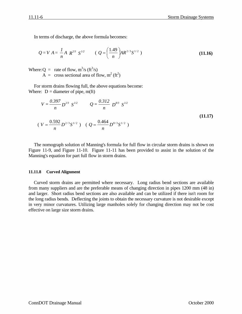
In terms of discharge, the above formula becomes:
(11.16)
Where:Q = rate of flow, m3/s (ft3/s)A = cross sectional area of flow, m2 (ft2)
For storm drains flowing full, the above equations become:Where: D = diameter of pipe, m(ft)
(11.17)
( 2/13/2592.0 SDn
V = ) ( 2/13/8464.0 SDn
Q = )
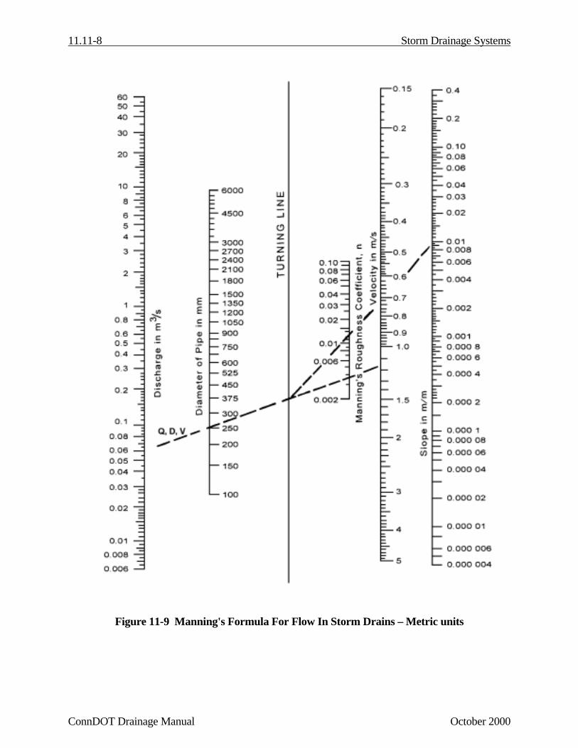
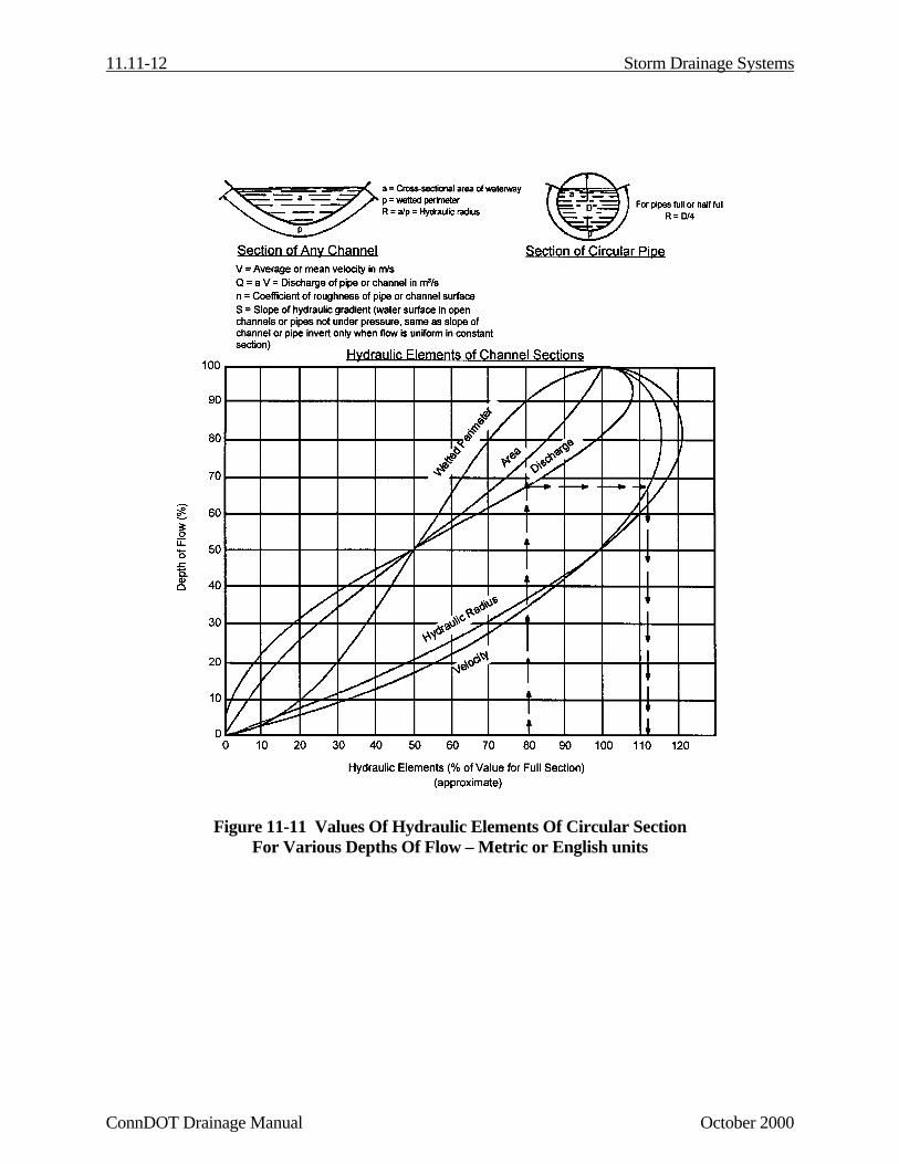
The nomograph solution of Manning's formula for full flow in circular storm drains is shown onFigure 11-9, and Figure 11-10. Figure 11-11 has been provided to assist in the solution of theManning's equation for part full flow in storm drains.
11.11.8 Curved Alignment
Curved storm drains are permitted where necessary. Long radius bend sections are availablefrom many suppliers and are the preferable means of changing direction in pipes 1200 mm (48 in)and larger. Short radius bend sections are also available and can be utilized if there isn't room forthe long radius bends. Deflecting the joints to obtain the necessary curvature is not desirable exceptin very minor curvatures. Utilizing large manholes solely for changing direction may not be costeffective on large size storm drains.
S R An1 =A V=Q 1/22/3 ( 2/13/249.1 SAR
nQ
= )
S D n
0.312=Q 1/28/3S Dn0.397=V 1/22/3

Storm Drainage Systems 11.11-7
October 2000 ConnDOT Drainage Manual
11.11.9 Minimum Grades
All storm drains should be designed such that velocities of flow will not be less than 0.9 m/s(3 ft/s) at design flow. For very flat grades the general practice is to design components so that flowvelocities will increase progressively throughout the length of the pipe system. The storm drainagesystem should be checked to be sure there is sufficient velocity in all of the drains to deter settling ofparticles. Minimum slopes required for a velocity of 0.9 m/s (3 ft/s) can be calculated by theManning's formula or use values given in Table 11-7.
(11.18)
Table 11-7
Minimum Slopes Necessary To Ensure 0.9 m/s (3 ft/s)In Storm Drains Flowing Full
Minimum Slopes m/m (ft/ft)Pipe Size, mm (in) Full Pipe, m3/s (ft3/s) n = 0.012 n = 0.013 n = 0.024200 (8) 0.030 (1.05) 0.0064 0.0075 0.0256250 (10) 0.046 (1.64) 0.0048 0.0056 0.0190300 (12) 0.067 (2.36) 0.0037 0.0044 0.0149375 (15) 0.104 (3.68) 0.0028 0.0032 0.0111450 (18) 0.150 (5.30) 0.0022 0.0026 0.0087525 (21) 0.204 (7.22) 0.0018 0.0021 0.0071600 (24) 0.267 (9.43) 0.0015 0.0017 0.0059675 (27) 0.338 (11.93) 0.0013 0.0015 0.0051750 (30) 0.417 (14.73) 0.0011 0.0013 0.0044825 (33) 0.505 (17.82) 0.00097 0.0011 0.0039900 (36) 0.601 (21.21) 0.00086 0.0010 0.00341050 (42) 0.817 (28.86) 0.00070 0.00082 0.00281200 (48) 1.067 (37.70) 0.00059 0.00069 0.00231350 (54) 1.351 (47.71) 0.00050 0.00059 0.00201500 (60) 1.668 (58.90) 0.00044 0.00051 0.00171650 (66) 2.018 (71.27) 0.00038 0.00045 0.00151800 (72) 2.402 (84.82) 0.00034 0.00040 0.0014
R)(nV = S
4/3
2
11.11-8 Storm Drainage Systems
ConnDOT Drainage Manual October 2000
Figure 11-9 Manning's Formula For Flow In Storm Drains – Metric units

Storm Drainage Systems 11.11-9
October 2000 ConnDOT Drainage Manual
Figure 11-9.1 Manning’s Formula For Flow In Storm Drains – English units

11.11-10 Storm Drainage Systems
ConnDOT Drainage Manual October 2000
Figure 11-10 Concrete Pipe Flow Nomograph – Metric units

Storm Drainage Systems 11.11-11
October 2000 ConnDOT Drainage Manual
Figure 11-10.1 Concrete Pipe Flow Nomograph – English units
11.11-12 Storm Drainage Systems
ConnDOT Drainage Manual October 2000
Figure 11-11 Values Of Hydraulic Elements Of Circular SectionFor Various Depths Of Flow – Metric or English units
Storm Drainage Systems 11.11-13
December 2003 ConnDOT Drainage Manual
Storm Drain Computation Sheet – MetricComputed Date Project
RouteChecked Date Station
Town
Station Flow Time, Tc(min)
A x C (8) (9) Pipe (17) Velocity(mps)
(1) (2) (3) (4) (5) (6) (7) (10) (11) (12) (13) Invert Elevation(m) (16) (18) (19)
(14) (15)
From
To
To Inlet
In Pipe
Accum
ulated
Increment
Total
Rainfall Intensity, I(m
m/hr)
Total Flow in System
,CIA
/ 360 = Q (cm
s)
Size
Type
"n"
Length (m)
Upstream
Dow
nstream
Slope (m/m
)
Full Capacity, QF (cm
s)
Flowing Full, V
F
Design Flow
, V
Table 11-8 Storm Drain Computation Sheet – Metric units
11.11-14 Storm Drainage Systems
ConnDOT Drainage Manual December 2003
Storm Drain Computation Sheet – EnglishComputed Date Project
RouteChecked Date Station
Town
Station Flow Time, Tc(min)
A x C (8) (9) Pipe (17) Velocity(fps)
(1) (2) (3) (4) (5) (6) (7) (10) (11) (12) (13) Invert Elevation(ft) (16) (18) (19)
(14) (15)
From
To
To Inlet
In Pipe
Accum
ulated
Increment
Total
Rainfall Intensity, I(in/hr)
Total Flow in System
,CIA
= Q (cfs)
Size
Type
"n"
Length (ft)
Upstream
Dow
nstream
Slope (ft/ft)
Full Capacity, QF (cfs)
Flowing Full, V
F
Design Flow
, V
Table 11-8 Storm Drain Computation Sheet – English units


![fB COst Contro Textbook 25[1].11.11](https://static.fdocuments.in/doc/165x107/544e61f4b1af9f23638b4db6/fb-cost-contro-textbook-2511111.jpg)