1111111111111111111inuuu1111111111u~ - NASA · R.Pino,R., and Pazienza, G. (eds), Springer Verlag....
30
1111111111111111111inuuu1111111111u~ (12) United States Patent Versace et al. (54) METHODS AND APPARATUS FOR AUTONOMOUS ROBOTIC CONTROL (71) Applicants:Neurala, Inc., Boston, MA (US); Trustees of Boston University, Boston, MA (US) (72) Inventors: Massimiliano Versace, Boston, MA (US); Anatoly Gorshechnikov, Newton, MA (US); Gennady Livitz, Belmont, MA (US); Jesse Palma, Somerville, MA (US) (73) Assignee: Neurala, Inc., Boston, MA (US) (*) Notice: Subject to any disclaimer, the term of this patent is extended or adjusted under 35 U.S.C. 154(b) by 0 days. (21) Appl. No.: 14/662,657 (22) Filed: Mar. 19, 2015 (65) Prior Publication Data US 2015/0269439 Al Sep. 24, 2015 Related U.S. Application Data (60) Provisional application No. 61/955,756, filed on Mar. 19, 2014. (51) Int. Cl. G06K 9/00 (2006.01) B25J 9/16 (2006.01) (Continued) (52) U.S. Cl. CPC ........ G06K 9/00664 (2013.01); B25J 9/1697 (2013.01); G06K 9/3241 (2013.01); (Continued) (58) Field of Classification Search None See application file for complete search history. (io) Patent No.: US 9,626,566 B2 (45) Date of Patent: Apr. 18, 2017 (56) References Cited U.S. PATENT DOCUMENTS 5,388,206 A 2/1995 Poulton et al. 6,336,051 131 1/2002 Pangels et al. (Continued) FOREIGN PATENT DOCUMENTS EP 1 224 622 131 7/2002 Wo WO 2014/190208 11/2014 (Continued) OTHER PUBLICATIONS International Preliminary Report on Patentability in related PCT Application No. PCT/US20 14/03 9 1 62 filed May 22, 2014, mailed Nov. 24, 2015, 7 pages. (Continued) Primary Examiner Atiba O Fitzpatrick (74) Attorney, Agent, or Firm Cooley LLP (57) ABSTRACT Sensory processing of visual, auditory, and other sensor information (e.g., visual imagery, LIDAR, RADAR) is con- ventionally based on "stovepiped," or isolated processing, with little interactions between modules. Biological sys- tems, on the other hand, fuse multi -sensory information to identify nearby objects of interest more quickly, more efli- ciently, and with higher signal-to-noise ratios. Similarly, examples of the OpenSense technology disclosed herein use neurally inspired processing to identify and locate objects in a robot's environment. This enables the robot to navigate its environment more quickly and with lower computational and power requirements. 16 Claims, 7 Drawing Sheets Objects i6tr.-tits;_ posiWxl, scene ider_tib" and composition https://ntrs.nasa.gov/search.jsp?R=20170004335 2019-02-23T01:40:00+00:00Z
Transcript of 1111111111111111111inuuu1111111111u~ - NASA · R.Pino,R., and Pazienza, G. (eds), Springer Verlag....
1111111111111111111inuuu1111111111u~(12) United States Patent
Versace et al.
(54) METHODS AND APPARATUS FORAUTONOMOUS ROBOTIC CONTROL
(71) Applicants:Neurala, Inc., Boston, MA (US);Trustees of Boston University, Boston,MA (US)
(72) Inventors: Massimiliano Versace, Boston, MA(US); Anatoly Gorshechnikov,Newton, MA (US); Gennady Livitz,Belmont, MA (US); Jesse Palma,Somerville, MA (US)
(73) Assignee: Neurala, Inc., Boston, MA (US)
(*) Notice: Subject to any disclaimer, the term of thispatent is extended or adjusted under 35U.S.C. 154(b) by 0 days.
(21) Appl. No.: 14/662,657
(22) Filed: Mar. 19, 2015
(65) Prior Publication Data
US 2015/0269439 Al Sep. 24, 2015
Related U.S. Application Data
(60) Provisional application No. 61/955,756, filed on Mar.19, 2014.
(51) Int. Cl.G06K 9/00 (2006.01)B25J 9/16 (2006.01)
(Continued)
(52) U.S. Cl.CPC ........ G06K 9/00664 (2013.01); B25J 9/1697
(2013.01); G06K 9/3241 (2013.01);
(Continued)(58) Field of Classification Search
NoneSee application file for complete search history.
(io) Patent No.: US 9,626,566 B2(45) Date of Patent: Apr. 18, 2017
(56) References Cited
U.S. PATENT DOCUMENTS
5,388,206 A 2/1995 Poulton et al.6,336,051 131 1/2002 Pangels et al.
(Continued)
FOREIGN PATENT DOCUMENTS
EP 1 224 622 131 7/2002Wo WO 2014/190208 11/2014
(Continued)
OTHER PUBLICATIONS
International Preliminary Report on Patentability in related PCTApplication No. PCT/US20 14/03 9 1 62 filed May 22, 2014, mailedNov. 24, 2015, 7 pages.
(Continued)
Primary Examiner Atiba O Fitzpatrick
(74) Attorney, Agent, or Firm Cooley LLP
(57) ABSTRACT
Sensory processing of visual, auditory, and other sensorinformation (e.g., visual imagery, LIDAR, RADAR) is con-ventionally based on "stovepiped," or isolated processing,with little interactions between modules. Biological sys-tems, on the other hand, fuse multi-sensory information toidentify nearby objects of interest more quickly, more efli-ciently, and with higher signal-to-noise ratios. Similarly,examples of the OpenSense technology disclosed herein useneurally inspired processing to identify and locate objects ina robot's environment. This enables the robot to navigate itsenvironment more quickly and with lower computationaland power requirements.
16 Claims, 7 Drawing Sheets
Objectsi6tr.-tits;_posiWxl,scene ider_tib"andcomposition
https://ntrs.nasa.gov/search.jsp?R=20170004335 2019-02-23T01:40:00+00:00Z
US 9,626,566 B2Page 2
(51) Int. Cl.
G06T 7/00 (2017.01)
G06K 9/32 (2006.01)
G06K 9/46 (2006.01)
G06T 7/20 (2017.01)
G06N 3100 (2006.01)
G06N 3104 (2006.01)
(52) U.S. Cl.
CPC ............ G06K 9/4628 (2013.01); G06T 7/004
(2013.01); G06T 7/0044 (2013.01); G06T
7/0081 (2013.01); G06T 712093 (2013.01);
G05B 2219139082 (2013.01); G06N 31008
(2013.01); G06N 31049 (2013.01); G06T
2207120141 (2013.01); G06T 2207/20144
(2013.01); G06T 2207/30244 (2013.01)
(56) References Cited
U.S.PATENT DOCUMENTS
6,647,508 B2 11/2003 Zalewski et al.7,861,060 B1 12/2010 Nickolls et al.7,873,650 B1 1/2011 Chapman et al.8,648,867 B2 2/2014 Gorchetchnikov et al.9,189,828 B2 11/2015 Gorchetchnikov et al.
2002/0046271 Al 4/2002 Huang2003/0078754 Al 4/2003 Hamza2004/0015334 Al 1/2004 Ditlow et al.2005/0166042 Al 7/2005 Evans2007/0052713 Al 3/2007 Chung et al.2007/0198222 Al 8/2007 Schuster et al.2007/0279429 Al 12/2007 Ganzer2008/0033897 Al 2/2008 Lloyd2008/0117220 Al 5/2008 Gorchetchnikov et al.2008/0258880 Al 10/2008 Smith et al.2009/0089030 Al 4/2009 Sturrock et al.2010/0048242 Al 2/2010 Rhoads et al.2011/0173015 Al 7/2011 Chapman et al.20 12/03 167 86 Al 12/2012 Liu et al.2014/0192073 Al 7/2014 Gorchetchnikov et al.2016/0082597 Al* 3/2016 Gorshechnikov ........ G06N 5/02
700/2532016/0198000 Al 7/2016 Gorchechnikov et al.
FOREIGN PATENT DOCUMENTS
WO WO 2014/204615 12/2014WO WO 2015/143173 9/2015WO WO 2016/014137 1/2016
OTHER PUBLICATIONS
International Preliminary Report on Patentability in related PCT
Application No. PCT/US20 14/03 923 9 filed May 22, 2014, mailed
Nov. 24, 2015, 8 pages.Adelson, E. H., Anderson, C. H., Bergen, J. R., Burt, P. J., & Ogden,J. M. (1984). Pyramid methods in image processing. RCA engineer,29(6), 33-41.Aggarwal, Charu C, Hinneburg, Alexander, and Keim, Daniel A. Onthe surprising behavior of distance metrics in high dimensionalspace. Springer, 2001.Ames, H. Mingolla, E., Sohail, A., Chandler, B., Gorchetchnikov,A., Lev6116, J., Livitz, G. and Versace, M. (2012) The Animal IEEEPulse, Feb. 2012, 3(1), 47-50.Ames, H, Versace, M., Gorchetchnikov, A., Chandler, B., Livitz, G.,Lev6116, J., Mingolla, E., Carter, D., Abdalla, H., and Snider, G.(2012) Persuading computers to act more like brains. In Advancesin Neuromorphic Memristor Science and Applications, Kozma,R.Pino,R., and Pazienza, G. (eds), Springer Verlag.Baraldi, A. and Alpaydin, E. (1998). Simplified ART: Anew classof ART algorithms. International Computer Science Institute,Berkeley, CA, TR-98-004, 1998.
Baraldi, A. and Alpaydin, E. (2002). Constructive feedforward ARTclustering networks Part L IEEE Transactions on Neural Net-works 13(3), 645-661.Baraldi, A. and Parmiggiani, F. (1997). Fuzzy combination ofKohonen's and ART neural network models to detect statisticalregularities in a random sequence of multi-valued input patterns. InInternational Conference on Neural Networks, IEEE.Baraldi, Andrea and Alpaydin, Ethem. Constructive feedforwardART clustering networks part IL IEEE Transactions on NeuralNetworks, 13(3):662-677, May 2002. ISSN 1045-9227. doi:10.1109/tnn.2002.1000131. URL http://dx.doi.org/10.1109/tnn.2002.1000131.Bengio, Y, Courville, A., & Vincent, P. (2013). Representationlearning: A review and new perspectives.Besl, P. J., & Jain, R. C. (1985). Three-dimensional object recog-nition. ACM Computing Surveys (CSUR), 17(1), 75-145.Bradski, G., & Grossberg, S. (1995). Fast-learning VIEWNETarchitectures for recognizing three-dimensional objects from mul-tiple two-dimensional views. Neural Networks, 8 (7-8), 1053-1080.Canny, J., A (1986) Computational Approach To Edge Detection,IEEE Trans. Pattern Analysis and Machine Intelligence, 8(6):679-698.Carpenter, G.A. and Grossberg, S. (1987). A massively parallelarchitecture for a self-organizing neural pattern recognitionmachine. Computer Vision, Graphics, and Image Processing 37,54-115.Carpenter, G.A., and Grossberg, S. (1995). Adaptive resonancetheory (ART). In M. Arbib (Ed.), The handbook of brain theory andneural networks. (pp. 79-82). Cambridge, M.A.: MIT press.Carpenter, G.A., Grossberg, S. and Rosen, D.B. (1991). Fuzzy ART:Fast stable learning and categorization of analog patterns by anadaptive resonance system. Neural Networks 4, 759-771.Carpenter, Gail A and Grossberg, Stephen. The art of adaptivepattern recognition by a self-organizing neural network. Computer,21(3):77-88, 1988.Coifman, R.R., Lafon, S., Lee, A.B., Maggioni, M., Nadler, B.,Warner, F., and Zucker, S.W. Geometric diffusions as a tool forharmonic analysis and structure definition of data: Diffusion maps.Proceedings of the National Academy of Sciences of the UnitedStates of America, 102(21):7426, 2005.Coifman, R.R. and Maggioni, M. Diffusion wavelets. Applied andComputational Harmonic Analysis, 21(1):53-94, 2006.Dosher, B.A., and Lu, Z.L. (2010). Mechanisms of perceptualattention in preening of location. Vision Res., 40(10-12). 1269-1292.Fazl, A., Grossberg, S., and Mingolla, E. (2009). View-invariantobject category learning, recognition, and search: How spatial andobject attention are coordinated using surface-based attentionalshrouds. Cognitive Psychology 58, 1-48.F61diak, P. (1990). Forming sparse representations by local anti-Hebbian learning, Biological Cybernetics, vol. 64, pp. 165-170.Friston K., Adams R., Perrinet L., & Breakspear M. (2012). Per-ceptions as hypotheses: saccades as experiments. Frontiers in Psy-chology, 3 (151), 1-20.Galbraith, B.V, Guenther, F.H., and Versace, M. (2015) A neuralnetwork-based exploratory learning and motor planning system forco-robots.Frontiers in Neuroscience, in press.George, D. and Hawkins, J. (2009). Towards a mathematical theoryof cortical micro-circuits. PLoS Computational Biology 5(10),1-26.Grossberg, S. (1973). Contour enhancement, short-term memory,and constancies in reverberating neural networks. Studies inApplied Mathematics 52, 213-257.Grossberg, S., and Huang, T.R. (2009). ARTSCENE: A neuralsystem for natural scene classification. Journal of Vision, 9 (4),6.1-19. doi:10.1167/9.4.6.Grossberg, S., and Versace, M. (2008) Spikes, synchrony, andattentive learning by laminar thalamocortical circuits. BrainResearch, 1218C, 278-312 [Authors listed alphabetically].Hassell, Hado Van. Double q-learning. In Advances in NeuralInformation Processing Systems, pp. 2613-2621,2010.Hinton, G. E., Osindero, S., and Teh, Y. (2006). A fast learningalgorithm for deep belief nets. Neural Computation, 18, 1527-1554.
US 9,626,566 B2Page 3
(56) References Cited
OTHER PUBLICATIONS
Itti, L., and Koch, C. (2001). Computational modelling of visualattention. Nature Reviews Neuroscience, 2 (3), 194-203.Itti, L., Koch, C., and Niebur, E. (1998). A Model of Saliency-BasedVisual Attention for Rapid Scene Analysis, 1-6.Jarrett, K., Kavukcuoglu, K., Ranzato, M. A., & LeCun, Y. (Sep.2009). What is the best multi-stage architecture for object recog-nition?. In Computer Vision, 2009 IEEE 12th International Confer-ence on (pp. 2146-2153). IEEE.Kompella, Varun Raj, Luciw, Matthew, and Schmidhuber, Rirgen.Incremental slow feature analysis: Adaptive low-complexity slowfeature updating from high-dimensional input streams. Neural Com-putation, 24(11):2994-3024, 2012.Kowler, E. (2011). Eye movements: The past 25years. VisionResearch, 51(13), 1457-1483. doi:10.1016/j.visres.2010.12.014.Larochelle H., & Hinton G. (2012). Learning to combine fovealglimpses with a third-order Boltzmann machine. NIPS 2010, 1243-1251.LeCun, Y, Kavukcuoglu, K., & Farabet, C. (May 2010). Convolu-tional networks and applications in vision. In Circuits and Systems(ISCAS), Proceedings of 2010 IEEE International Symposium on(pp. 253-256). IEEE.Lee, D. D. and Seung, H. S. (1999). Learning the parts of objectsby non-negative matrix factorization. Nature, 401(6755):788-791.Lee, D. D., and Seung, H. S. (1997). "Unsupervised learning byconvex and conic coding." Advances in Neural Information Pro-cessing Systems, 9.Legenstein, R., Wilbert, N., and Wiskott, L. Reinforcement learningon slow features of high-dimensional input streams. PLoS Compu-tational Biology, 6(8), 2010. ISSN 1553-734X.L&6116, J., Ames, H., Chandler, B., Gorchetchnikov, A., Mingolla,E., Patrick, S., and Versace, M. (2010) Learning in a distributedsoftware architecture for large-scale neural modeling. BIONET-ICS10, Boston, MA, USA.Livitz G., Versace M., Gorchetchnikov A., Vasilkoski Z., Ames H.,Chandler B., Leveille J. and Mingolla E. (2011) Adaptive, brain-likesystems give robots complex behaviors, The Neuromorphic Engi-neer: 10.2417/1201101.003500 Feb. 2011.Livitz, G., Versace, M., Gorchetchnikov, A., Vasilkoski, Z., Ames,H., Chandler, B., Lev6116, J., Mingolla, E., Snider, G., Amerson, R.,Carter, D., Abdalla, H., and Qureshi, S. (2011) Visually-GuidedAdaptive Robot (ViGuAR). Proceedings of the International JointConference on Neural Networks (IJCNN) 2011, San Jose, CA,USA.Lowe, D.G.(2004). Distinctive Image Features from Scale-InvariantKeypoints. Journal International Journal of Computer Visionarchive vol. 60, 2, 91-110.Lu, Z.L., Liu, J., and Dosher, B.A. (20 10) Modeling mechanisms ofperceptual learning with augmented Hebbian re- weighting. VisionResearch, 50(4). 375-390.Mahadevan, S. Proto-value functions: Developmental reinforce-ment learning. In Proceedings of the 22nd international conferenceon Machine learning, pp. 553-560. ACM, 2005.Mishkin M, Ungerleider LG. (1982). "Contribution of striate inputsto the visuospatial functions of parieto-preoccipital cortex in mon-keys," Behav Brain Res, 6 (1): 57-77.Mnih, Volodymyr, Kavukcuoglu, Koray, Silver, David, Rusu,Andrei A, Veness, Joel, Bellemare, Marc G, Graves, Alex,Riedmiller, Martin, Fidjeland, Andreas K, Ostrovski, Georg, et al.Human-level control through deep reinforcement learning. Nature,518(7540):529-533, 2015.Moore, Andrew W and Atkeson, Christopher G. Prioritized sweep-ing: Reinforcement learning with less data and less time. MachineLearning, 13(1):103-130, 1993.Najemnik, J., and Geisler, W. (2009). Simple summation rule foroptimal fixation selection in visual search. Vision Research. 49,1286-1294.Oja, E. (1982). Simplified neuron model as a principal componentanalyzer. Journal of Mathematical Biology 15(3), 267-273.
Raudies, F., Eldridge, S., Joshi, A., and Versace, M. (2014). Learn-ing to navigate in a virtual world using optic flow and stereodisparity signals. Artificial Life and Robotics, DOI 10.1007/s10015-014-0153-1.Raijmakers, M.E.J., and Molenaar, P. (1997). Exact ART: A com-plete implementation of an ART network Neural networks 10 (4),649-669.Ranzato, M. A., Huang, F. J., Boureau, Y L., & Lecun, Y (Jun.2007). Unsupervised learning of invariant feature hierarchies withapplications to object recognition. In Computer Vision and PatternRecognition, 2007. CVPR'07. IEEE Conference on (pp. 1-8). IEEE.Riesenhuber, M., & Poggio, T. (1999). Hierarchical models ofobject recognition in cortex. Nature Neuroscience, 2 (11), 1019-1025.Riesenhuber, M., & Poggio, T. (2000). Models of object recogni-tion. Nature neuroscience, 3, 1199-1204.Rublee, E., Rabaud, V., Konolige, K., & Bradski, G. (2011). ORB:An efficient alternative to SIFT or SURF. In IEEE InternationalConference on Computer Vision (ICCV) 2011, 2564-2571.Rumelhart D., Hinton G., and Williams, R. (1986). Learning inter-nal representations by error propagation. In Parallel distributedprocessing: explorations in the microstructure of cognition, vol. 1,MIT Press.Salakhutdinov, R., & Hinton, G. E. (2009). Deep boltzmannmachines. In International Conference on Artificial Intelligence andStatistics (pp. 448-455).Schaul, Tom, Quan, John, Antonoglou, Ioannis, and Silver, David.Prioritized experience replay. arXiv preprint arXiv: 1511.05952,2015.Schmidhuber, J. (2010). Formal theory of creativity, fun, andintrinsic motivation (1990-2010). Autonomous Mental Develop-ment, IEEE Transactions on, 2(3), 230-247.Schmidhuber, Jurgen. Curious model-building control systems. InNeural Networks, 1991. 1991 IEEE International Joint Conferenceon, pp. 1458-1463. IEEE, 1991.Seibert, M., & Waxman, A.M. (1992). Adaptive 3-D Object Rec-ognition from Multiple Views. IEEE Transactions on Pattern Analy-sis and Machine Intelligence, 14 (2), 107-124.Sherbakov, L., Livitz, G., Sohail, A., Gorchetchnikov, A., Mingolla,E., Ames, H., and Versace, M. CogEye: An online active visionsystem that disambiguates and recognizes objects. NeuComp 2013.Sherbakov, L., Livitz, G., Sohail, A., Gorchetchnikov, A., Mingolla,E., Ames, H., and Versace, M (2013b) A computational model of therole of eye-movements in object disambiguation. Cosyne, Feb.28-Mar. 3, 2013. Salt Lake City, UT, USA.Sherbakov, L. and Versace, M. (2014) Computational principles foran autonomous active vision system. Ph.D., Boston University,http://search.proquest.com/docview/1558856407.Smolensky, P. (1986). Information processing in dynamical sys-tems: Foundations of harmony theory. In D. E.Snider, G., Amerson, R., Carter, D., Abdalla, H., Qureshi, S.,Laveille, J., Versace, M., Ames, H., Patrick, S., Chandler, B.,Gorchetchnikov, A., and Mingolla, E. (20 10) Adaptive Computationwith Memristive Memory. IEEE Computer, vol. 44(2).Spratling, M. W. (2008). Predictive coding as a model of biasedcompetition in visual attention. Vision Research, 48(12):1391-1408.Spratling, M. W., De Meyer, K., and Kompass, R. (2009). Unsu-pervised learning of overlapping image components using divisiveinput modulation. Computational intelligence and neuroscience.Spratling, M. W. (2012). Unsupervised learning of generative anddiscriminative weights encoding elementary image components in apredictive coding model of cortical function. Neural Computation,24(1):60-103.Sprekeler, H. On the relation of slow feature analysis and laplacianeigenmaps. Neural Computation, pp. 1-16, 2011.Sutton, R. S., and Barto, A. G. (1998). Reinforcement learning: Anintroduction(vol. 1, No. 1). Cambridge: MIT press.Tong, F., Ze-Nian Li, (1995). Reciprocal-wedge transform forspace-variant sensing, Pattern Analysis and Machine Intelligence,IEEE Transactions on , vol. 17, No. 5, pp. 500-51. doi: 10.1109/34.391393.
US 9,626,566 B2Page 4
(56) References Cited
OTHER PUBLICATIONS
Torralba, A., Oliva, A., Castelhano, M.S., Henderson, J.M. (2006).Contextual guidance of eye movements and attention in real-worldscenes: the role of global features in object search. PsychologicalReview, 113(4).766-786.Van Hasselt, Hado, Guez, Arthur, and Silver, David. Deep rein-forcement learning with double q-learning. arXiv preprint arXiv:1509.06461, 2015.Versace, M. From spikes to interareal synchrony: how attentive
matching and resonance control learning and information process-
ing by laminar thalamocortical circuits. NSF Science of Learning
Centers PI Meeting, Washington, DC, USA. (2006).
Versace, M., Ames, H., Lev6116, J., Fortenberry B., andGorchetchnikov, A. (2008) KInNeSS: A modular framework forcomputational neuroscience. Neuroinformatics, 2008 Winter;6(4):291-309. Epub Aug. 10, 2008.
Versace, M., (2010) Open-source software for computational neu-roscience: Bridging the gap between models and behavior. InHorizons in Computer Science Research, vol. 3.Versace, M., and Chandler, B. (20 10) MoNETA: A Mind Made fromMemristors. IEEE Spectrum, Dec. 2010.Wiskott, Laurenz and Sejnowski, Terrence. Slow feature analysis:Unsupervised learning of invariances. Neural Computation,14(4):715-770, 2002.Webster, Bachevalier, Ungerleider (1994). Connections of IT areasTEO and TE with parietal and frontal cortex in macaque monkeys.Cerebal Cortex, 4(5), 470-483.Artificial Intelligence As a Service. Invited talk, Defrag,Broomfield, CO, Nov. 4-6, 2013.Brain-inspired computing. Invited keynote address, Bionetics 2010,Boston, MA, USA.TEDx Fulbright, Invited talk, Washington DC, Apr. 5, 2014.U.S. Appl. No. 15/262,637, filed Sep. 12, 2016, Gorchetchnikov etal.U.S. Appl. No. 15/343,673, filed Nov. 4, 2016 Gorchetchnikov et al.
* cited by examiner
10
II
ME
Actu
ator
(Sen
sior
movement)
170
NN-that Pat
hwaya
NVIlat, Sys
tem
Teac
her
150
160
Objects
scen
e id
enti
tyand
Comp
osit
ion
FIG.
1
U.S. Patent Apr. 18, 2017 Sheet 2 of 7 US 9,626,566 B2
v......... ... ............. . . . .......
n
,.t.
<- r,
-:t fC%r..:
6ci:
v a
Gt
kat.. J
S .'.
~yW
'ax.
G.
~t» # c3
.ZI ~'• '7 yam.
.>+ _
.s'.:
°y:y Si -
k" +.
siO,ea'
.3r
V
+~f
~yHS r, w
~qM
i~.
15r~} .
i
FIG.
✓
U.S. Patent Apr. 18, 2017 Sheet 4 of 7 US 9,626,566 B2
U.S. Patent
Ln
ccLr
Apr. 18, 2017 Sheet 5 of 7 US 9,626,566 B2
Im
ACQUIRE IMAGES OF
IDENTIFY OBJECT IN
ROBOT'S
FIRS
T IMAGE USING
ENVIRONMENT
SPATIAL SHROUD
602
610
TRANSLATE AT LEAST
TRANSLATE SPATIAL
FIRS
T IMAGE TO
ALLOCENTRIC
SHROUD BASED ON
REFERENCE FRAME
SECOND IMAGE
r_ r%
612
DETERMINE IF SPATIAL
SEGMENT IMAGES
SHROUD FIT
S OBJECT
606
IN SECOND IMAGE
614
FIT SP
ATIA
L SHROUD
MOVE/ORIENT
TO FIRST IMAGE
CAMERA/ROBOT
608
616
FIG.
s V
i
U.S. Patent Apr. 18, 2017 Sheet 7 of 7 US 9,626,566 B2
N0
N0
W.r• ZZ
I
d0
US 9,626,566 B2
METHODS AND APPARATUS FORAUTONOMOUS ROBOTIC CONTROL
CROSS-REFERENCE TO RELATED PATENTAPPLICATION
This application claims priority, under 35 U.S.C. § I I9(e),from U.S. Application No. 61/955,756, filed Mar. 19, 2014,and entitled "Methods and Apparatus for AutonomousRobotic Control," which application is hereby incorporatedherein by reference in its entirety.
GOVERNMENT SUPPORT
This invention was made with government support underContract No. FA8750-12-C-0123 awarded by Air ForceResearch Laboratory (AFRL), under Contract No.NNXI2CG32P awarded by NASA Phase I STTR, and underContract No. NNX13CL63C awarded by NASA Phase IISTTR. The government has certain rights in the invention.
BACKGROUND
For a mobile robot to operate autonomously, it should beable to locate obstacles and steer around them as it moveswithin its environment. For example, a mobile robot mayacquire images of its environment, process them to identifyand locate obstacles, then plot a path around the obstaclesidentified in the images. In some cases, a mobile robot mayinclude multiple cameras, e.g., to acquire stereoscopic imagedata that can be used to estimate the range to certain itemswithin its field of view. A mobile robot may also use othersensors, such as radar or lidar, to acquire additional dataabout its environment. Radar is particularly useful for peer-ing through smoke or haze, and lidar returns can sometimesbe used determine the composition of objects within theenvironment. A mobile robot may fuse lidar, radar, and/orother data with visible image data in order to more accu-rately identify and locate obstacles in its environment. Todate, however, sensory processing of visual, auditory, andother sensor information (e.g., LIDAR, RADAR) is conven-tionally based on "stovepiped," or isolated processing, withlittle interaction between modules.
SUMMARY
Embodiments of the present invention include a systemfor identifying and locating objects in a robot's environ-ment. Such a system may include an image sensor andprocessor operably coupled to the image sensor. In opera-tion, the image sensor acquires a plurality of images of atleast a portion of the environment surrounding the robot.The processor translates each image in the plurality ofimages from the image sensor's frame of reference to anallocentric frame of reference. The processor identifies aposition, in the allocentric frame of reference, of an objectappearing in at least one image in the plurality of images.And the processor determines if the object appears in at leastone other image in the plurality of images based on theposition, in the allocentric frame of reference, of the object.
It should be appreciated that all combinations of theforegoing concepts and additional concepts discussed ingreater detail below (provided such concepts are not mutu-ally inconsistent) are contemplated as being part of theinventive subject matter disclosed herein. In particular, allcombinations of claimed subject matter appearing at the endof this disclosure are contemplated as being part of the
2inventive subject matter disclosed herein. It should also beappreciated that terminology explicitly employed herein thatalso may appear in any disclosure incorporated by referenceshould be accorded a meaning most consistent with the
5 particular concepts disclosed herein.
BRIEF DESCRIPTION OF THE DRAWINGS
The skilled artisan will understand that the drawings10 primarily are for illustrative purposes and are not intended to
limit the scope of the inventive subject matter describedherein. The drawings are not necessarily to scale; in someinstances, various aspects of the inventive subject matterdisclosed herein may be shown exaggerated or enlarged in
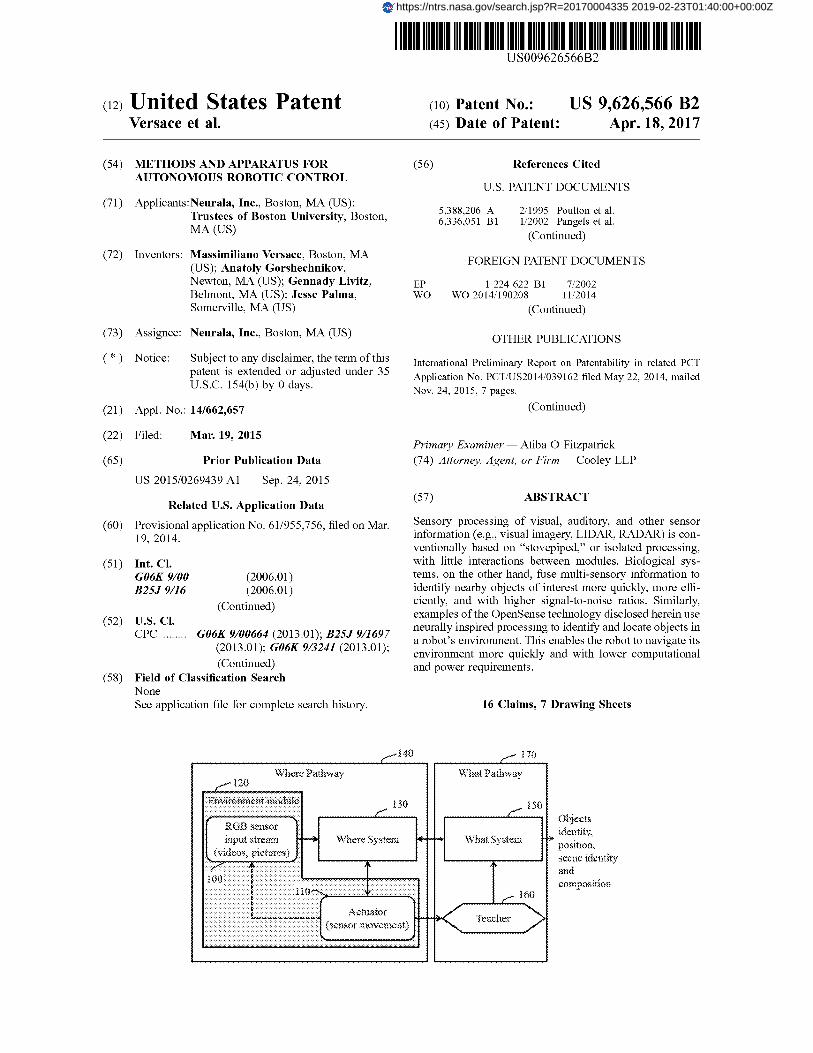
15 the drawings to facilitate an understanding of differentfeatures. In the drawings, like reference characters generallyrefer to like features (e.g., functionally similar and/or struc-turally similar elements).FIG.1 is a block diagram of an example OpenEye system.
20 FIG. 2 is a block diagram of the Where Pathway moduleshown in FIG. 2.FIG. 3 is a block diagram of the What Pathway module
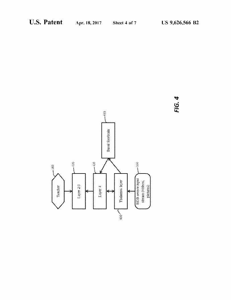
shown in FIG. 2.FIG. 4 is a block diagram of an alternative classifier
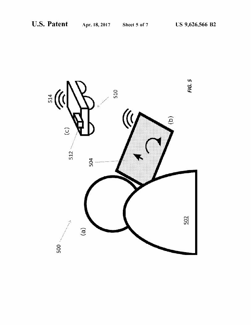
25 architecture suitable for implementing the view layer and theobject layer in the What Pathway module shown in FIG. 3.FIG. 5 illustrates control of a robot using the OpenEye
system via a remote controller, such as a tablet or smart-phone.
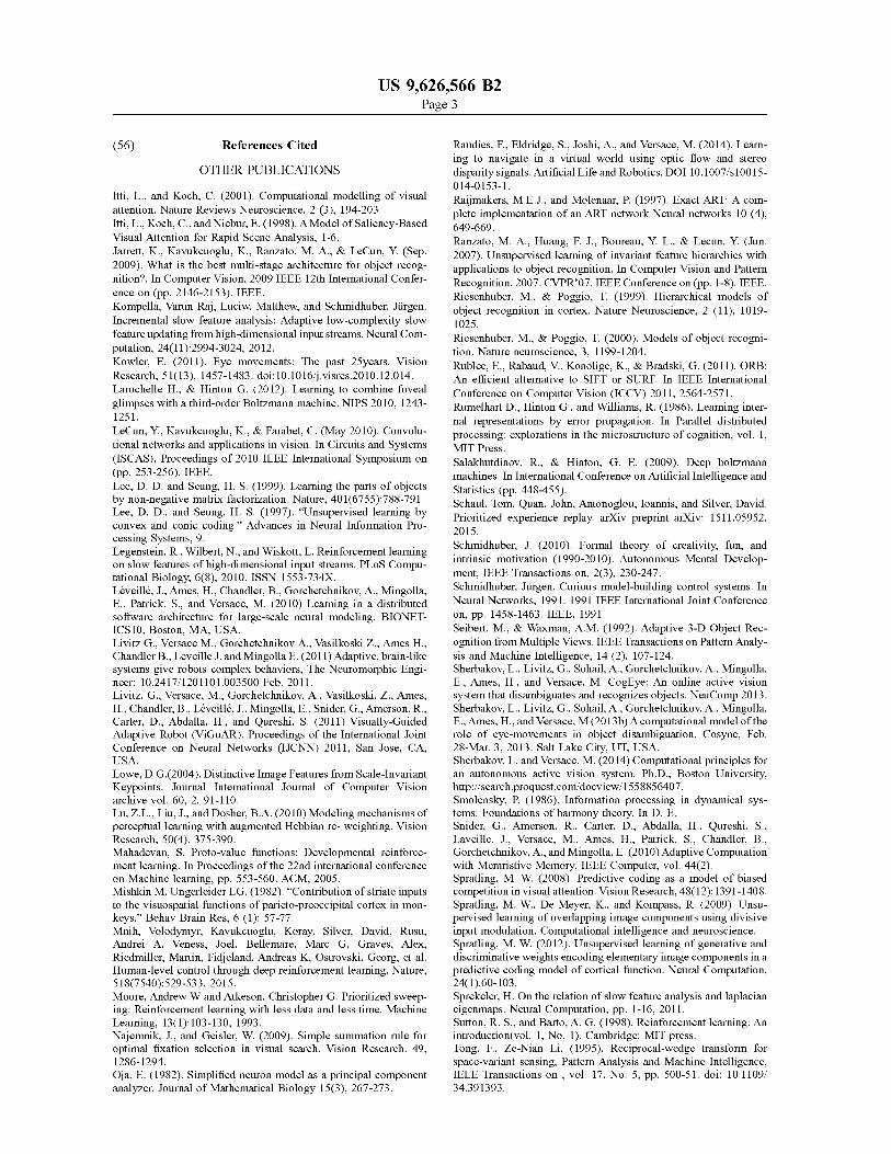
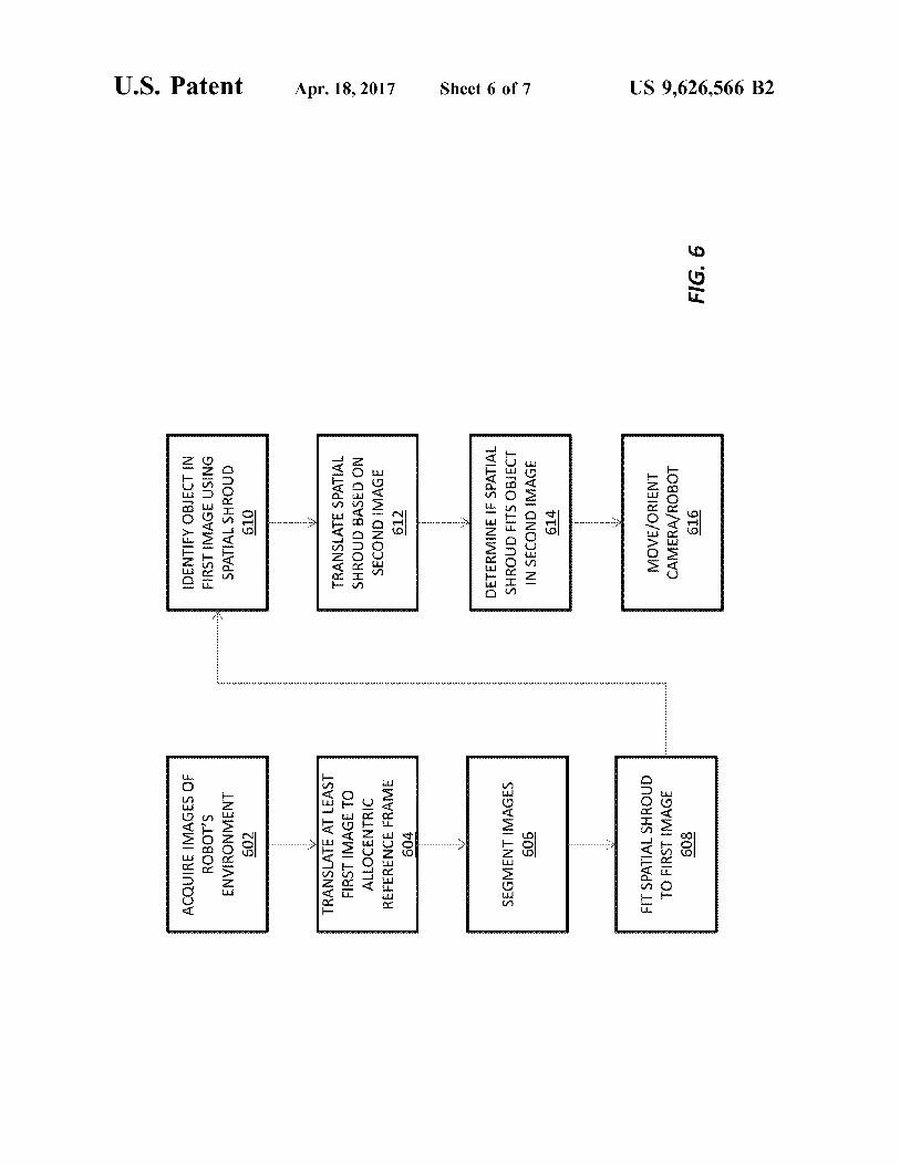
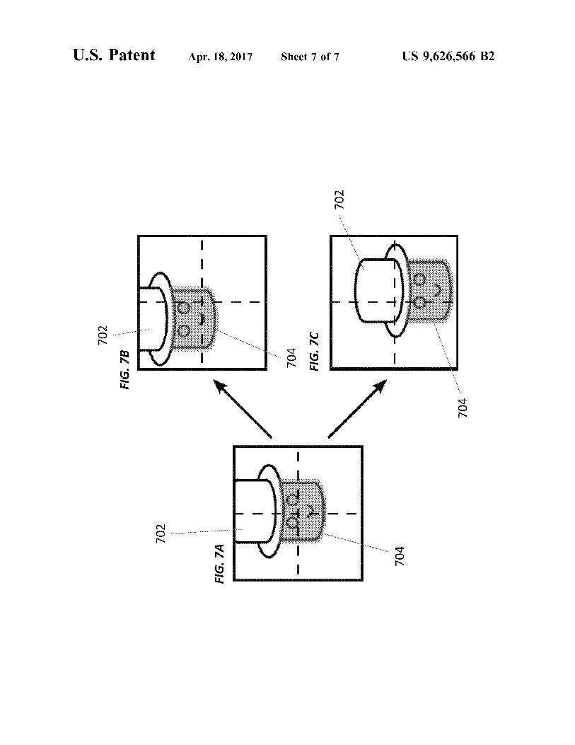
30 FIG. 6 illustrates a process for identifying and locatingobjects in a robot's environment by fitting a spatial shroudto successive images of the robot's environment.FIGS. 7A-7C show fitting a spatial shroud to an object in
different images of the robot's environment.35
DETAILED DESCRIPTION
The methods described herein provide an exemplaryunified technology for identifying, learning, localizing, and
40 tracking objects based on camera (e.g., RGB) input. Someexamples of this technology are called "OpenEye" and canbe implemented as an artificial, active sensory system and aunified framework for processing sensor data, including butnot limited to image data. OpenEye may be utilized in both
45 artificial (e.g., simulated environments, such as an environ-ment generated synthetically via a video-game engine) andnatural environments (e.g., an environment experienced byan unmanned aerial, ground, or submersible vehicle).In operation, OpenEye learns incrementally about its
50 visual input, and identifies objects in the sensor field of viewand categorizes those objects by identity and position.OpenEye can operate with or without supervision, and doesnot require a manual labeling of object of interest to learnobject identity. OpenEye can also accept user input to
55 verbally label objects.OpenEye simulates mammalian brains' dorsal (where
controlling where to look) and ventral (what—controllingthe content of the image) pathways by using simulated eyemovements (in virtual or real cameras) to learn identity of
60 objects in complex images (see, e.g., Mishkin and Unger-leider 1982 and Webster et al., 1994).
In some implementations OpenEye uses a space-variant,log-polar representation of the input visual field to samplethe image "view" generated by each eye movement. The
65 log-polar representation provides some invariance to trans-lation/rotation, and substantial savings in processing timewith better scalability to large datasets by employing non-
US 9,626,566 B23
uniform input sampling and rapid scan of image segments,as opposed to processing the whole image at uniformresolution (Traver and Bernardino, 2010). The model usesthe what-to-where feedback to sample the image intelli-gently. OpenEye does so by using the knowledge of the 5
identity of the current object and its context to focus onspatial locations that yield greatest disambiguation of com-peting object identity (e.g., areas of an image that are moreunique to an object). OpenEye may be validated on naturaland synthetic images, as well as on the standard MNIST iohandwritten digit dataset.As opposed to other approaches (e.g., neural networks),
the OpenEye system may not rely on extensive training(batch training) to be able to classify correctly objects in thedata stream, and can learn new knowledge online (i.e., 15during performance) without corrupting or forgetting previ-ously learned knowledge. Additionally, the system is able toautonomously search for information in an image via anactive visual search process, which mimics the mechanismused by mammals to rapidly and efficiently scan their visual 20world for important information. OpenEye memory systemis designed to allow on-line optimization of synaptic memo-ries. Additionally, OpenEye can mimic human eye move-ments by reproducing human fixation patterns with or with-out a training session where OpenEye learns the fixation 25location of a human user via eye-tracker.
Neurally Inspired Robot Perception, Object Identification,and Object LocationA conventional robot does not perceive its environment
like a human. For example, a robot may "see" its environ- 30ment by acquiring imagery of some or all or its environmentat a uniform resolution. It then processes the imagery bydividing the imagery into a grid of pixels and examiningeach pixel in the grid. This process can take too much timeand too much energy to be useful for identifying objects 35moving relative to the robot, especially if the robot ismoving at relatively high velocity (e.g., a drone flying at lowaltitude). In addition, the robot may spend an inordinateamount of time processing empty or irrelevant pixels.A human does not process the detail of entire images on 40
a pixel-by-pixel basis. Instead, the human eye acquiresimagery of non-uniform resolution: the central part of theretina, or fovea, which is densely packed with light-sensitivecones, acquires the central part of each image at relativelyfine resolution. And the peripheral portion of the retina, 45which is covered at lower density with light-sensitive rodsand cones, acquires the peripheral portion of each image atcoarser resolution. The resulting "foveated imagery" hasresolution that varies spatially across each image, with thefinest resolution at a fixation point and coarser resolution 50elsewhere. This notion of obtaining imagery at a resolutionthat varies spatially across each image is referred to hereinas "foveation."To account for the spatial variation in image resolution, a
human moves his or her eyes rapidly among different points 55in his or her field of view. For instance, a human may fixateon points at or near an interesting portion of a scene, suchas a face, for relatively long periods, and fixate on points ator near less interesting portions of the scene, such as a tree,for shorter periods, if at all. These quick, simultaneous 60movements to different fixation points, or saccades, allow ahuman to identify and locate items of interest withoutspending time or energy examining interesting portions ofthe scene.
Similarly, the OpenEye technology disclosed herein 65allows a robot to identify and locate objects in its environ-ment using "foveated" data collection and "saccade" style
4imaging as explained below with respect to FIGS. 1-4. Forinstance, one or more processors may control collection andprocessing of visual imagery according to a neural modelinspired by the human brain. A camera or other sensoracquires imagery of the robot's environment and passes thisimagery to a graphics processing unit (GPU) or othersuitable processor, which locates and identifies one or moreobjects in the imagery (e.g., using the What and Wherepathways described in greater detail below) based on theimagery itself and information about the sensor's orienta-tion, position, and/or field of view. In some cases, the GPUmay translate the imagery among different frames of refer-ence, including camera-centered, robot-based egocentric,and allocentric frames of reference, to make processingmore efficient and/or more precise.The processor also determines the next fixation point of
the sensor system based on the location and/or identity of theobject(s). In some cases, it transmits movement vectorrepresenting the saccade between the current fixation pointand the next fixation point to an actuator that then actuatesthe sensor appropriately. For instance, the processor maycause a pan-tilt actuator to move a camera mounted on therobot so as to acquire imagery of an object from differentangles and/or positions. The robot itself may move to changethe sensor's field of view. In other cases, the processor maycause synthetic "saccades," e.g., by processing differentportions of the same image or different portions of differentimages at different resolutions depending on the objects andtheir locations. The robot may also use object informationand sensor position and orientation data to inhibit the sensorfrom fixating repeatedly on the same object or the sameportion of the scene.
Because the technology disclosed herein mimics humanneural processing, it can process imagery and other sensorydata more efficiently and identify objects in the robot'senvironment more quickly. This is especially useful forrobots in hazardous applications, such as planetary explo-ration, where processing and battery efficiency are critical,and for robots that collect large volumes of data, suchsurveillance drones, where efficient sense-making is key tointerpreting large amounts of real-time data. It also hasgeneral application to all types of vision systems, includingsimulations, such as those used in video games, flightsimulators, etc.
Visual Stream Exploration and Visual Object LearningThe OpenEye model proposes a method for combining
visual stream exploration and visual object learning. Each isconsidered below.
Visual Stream Exploration ModelsThe computational model proposed by Itti and Koch
(2001) simulates an aspect of human vision that predicts theprobability that a certain image area will attract an observ-er's attention and eye movements. The model only includesbottom-up, or sensory features, while OpenEye alsoaccounts for cognitive (top-down) biases on eye movements.Additionally, the model does not include learning, object, orscene recognition, which are instead incorporated in Open-Eye, where they bias image stream exploration as discussedbelow.OpenEye also differs from Riesenhuber and Poggio's
(1999) neural model, which employs a spatially homog-enous representation of the image vs. OpenEye's spatiallyvariant representation and use of sensor movement. Both theItti & Koch (2001) and Riesenhuber & Poggio (1999)models postulate that visual objects need to be identified inone glance. OpenEye, instead, accounts for the potentialneed to explore the input sensory image to gather additional
US 9,626,566 B25
evidence for recognition, which is particularly useful forambiguous objects/scenes (e.g., occluded objects).
Visual Object Learning ModelsIn terms of learning, OpenEye may use two interchange-
able learning methodologies. The first method is based onthe Baraldi and Alpaydin (1998, 2002) and Baraldi andParmiggiani (1997) learning models, which provide thefollowing benefits. The second method is based on a recur-rent adaptive architecture. Both methodologies simultane-ously implement fast and slow learning.
Usually, fast learning (e.g., Carpenter and Grossberg,1987) systems underperform slow-learning ones (Rumelhartet al., 1986), but the former are much more useful inengineered system such as robots or sensors operating inreal-time in a rapidly changing environment. After onlysingle instance of presentation of each item, humans andother animals can learn to recognize pictures, words, names,and faces, and recording at a local cellular level confirmsthat neurons can change to reflect such fast learning (Bun-zeck & Dfizel, 2006; Rutishauser et al., 2006). To date, noartificial system has been engineered to achieve this goal ina machine.
Several object recognition algorithms have been devel-oped over the last few decades (for reviews, see Besl andJain, 1985; Logothetis and Sheinberg, 1996; Riesenhuberand Poggio, 2000; Bengio et al., 2012). In general, acommonality between these algorithms is the focus onfinding the appropriate representation for the data, where thedifference among algorithms performance is due to thenature of the features/input data transformations. Forinstance, convolutional network models (Ranzato et al.,2007; Jarrett et al. 2009; LeCun et al., 2010) and restrictedBoltzmann machines (Smolensky, 1986; Salakhutdinov andHinton, 2009) are among the best object recognition algo-rithms. Both classes of algorithms perform three main steps:a) feature extraction. This can be either hardwired, random,or learned;b) non-linear transformation on the resulting filtered data;andc) A pooling step on the result of step b). The connectivitybetween stages and the number of filter-transform-poolstages can vary.Deep learning networks include networks where there are
several layers of stacked filter-transform-pool, e.g. in theHMAX model (Riesenhuber & Poggio, 1999) and deepbelief networks (Hinton et al., 2006).
Similarly, Spratling (2008, 2009, 2012) has introducedseveral recognition systems built of stackable "cortical"modules. These models are composed of modules that workhierarchically and perform a process called "predictivecoding", that looks very akin to matching in an ART system.A close examination of the derivation of the learning laws inthese systems (Spratling et al., 2009) reveals that they weredeveloped as an incremental version of a well-known batchcoding algorithm, non-negative matrix factorization (NMF),developed by Lee and Seung (1997, 1999). The algorithmpresented by Spratling at al. does allow incremental (fast)learning, but does not include methods for object segrega-tion/segmentation, scene recognition, and active vision.
However, none of the above-mentioned object recogni-tion algorithms deals with the issues of how objects areseparated from their background, and neither of those mod-els uses space-variant sampling.The ARTScan (Fazl et al., 2009) model, the saccading
restricted Boltzmann machine (sRBM) (Larochelle & Hin-ton, 2012), and the entropy minimization algorithm ofsaccades (Friston et al., 2012)
6The saccading restricted Boltzmann machine (Larochelle
and Hinton, 2012) uses space variant vision. However, itdoes not include a mechanism that informs the system whenthe system stops fixation from an object and starts fixating
5 on another, which is provided by a human supervisor. Thesystem could not tell apart two identical objects presentedside-by-side with a spatial gap separating them.The entropy minimization algorithm of saccades (Friston
et al., 2012) includes bi-directional What-to-Where streamio interactions but does not use space-variant vision, and it
suffers from the same issue as Larochelle and Hinton (2012)in terms of object fixation memory.The ARTScan (Fazl et al., 2009) model includes Where-
to-What interaction in guiding when the What system should15 learn/stop learning, but does not include What-to-Where
interactions to inform eye movement and visual search.Additionally, OpenEye differs from ARTScan in these addi-tional dimensions:OpenEye and ARTScan use a different log-polar sam-
20 pling;OpenEye shroud formation is feed-forward;OpenEye is designed to operate in 3D environments in a
noisy background;OpenEye is designed to handle self-motion;
25 OpenEye employs a concept of temporal continuity tosupport dynamic scenes;OpenEye can combine multiple saliencies, endogenous
spatial attention, attention to specific features in order tomake next saccade; and
30 While ARTScan used handcrafted images OpenEye canbe used with arbitrary image data, such as the standardMNIST database;
Object learning models from Baloch and Waxman (1991),Bradski and Grossberg, (1995), Seibert and Waxman (1992)
35 do use space-variant transformation, or "cortical magnifica-tion", but only focus statically at an object's center-of-mass.OpenEye methods discussed in Sections 4 employ a
learning scheme that maximizes memory efficiency in termsof learning accuracy and capacity to enable both fast and
40 slow stable learning of sensory features.Benefits and ApplicationsBenefits of these methods and systems include providing
a single process for identifying, learning, localizing, andtracking objects in visual scenes provided by cameras.
45 Exemplary methods allow quick and stable learning of newpatterns without the need to retrain the system, while reduc-ing network (system) size and communication betweensystem components with respect to competing models. Themethod allows continuous learning of arbitrary sensory
5o representations in hierarchies of rate-based or spike-basedneural processing stages connected by adaptive (learnable)synaptic weights. An additional benefit of this method is toallow fast learning of new stimuli without the need tointerrupt the functioning of the machine, e.g., allowing a
55 robot with a camera to quickly learn the identity of a new,previously unlearned input without the need to retrain pre-viously seen input.The novel method presented herein can have application
in designing software to either extract information or control60 mobile robots or cameras. In particular, the method allows
these machines to increase their knowledge base over timewithout the need to retrain the system on the entire knowl-edge base.OpenEye Overview
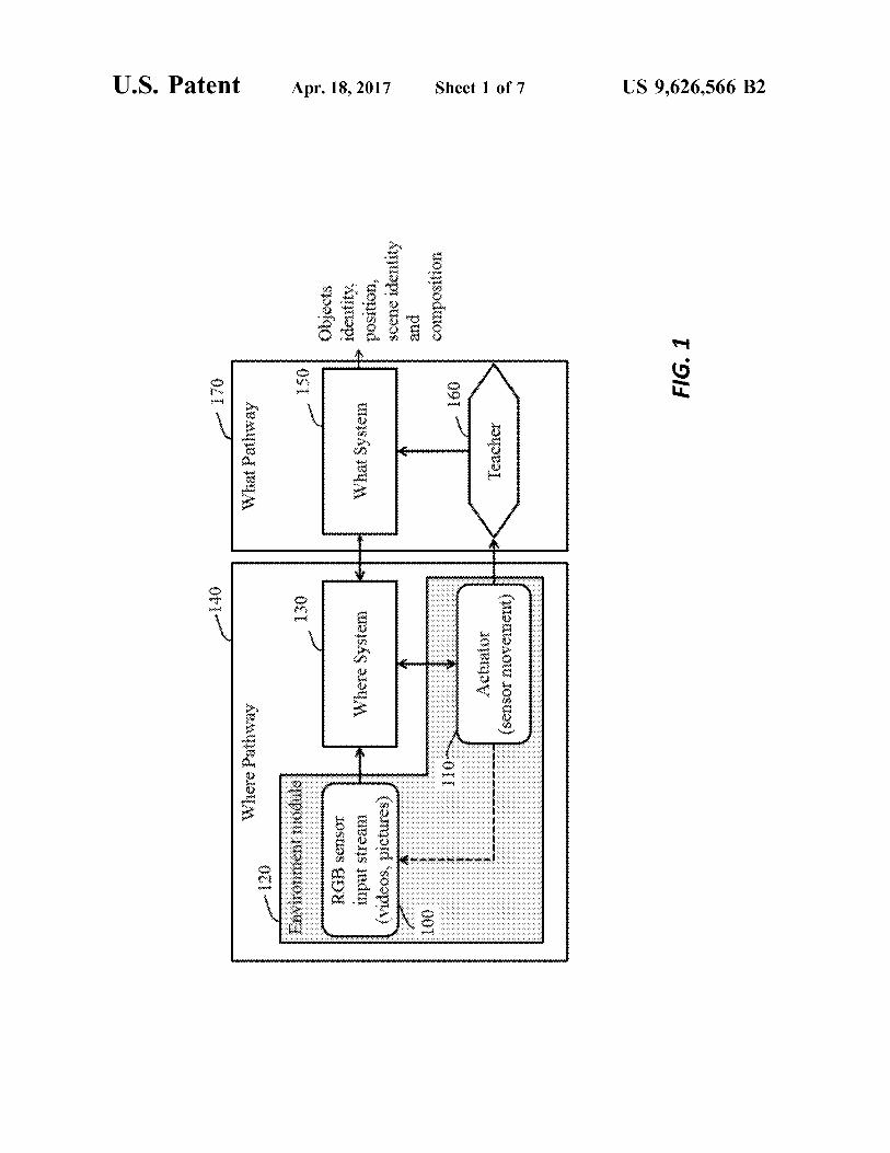
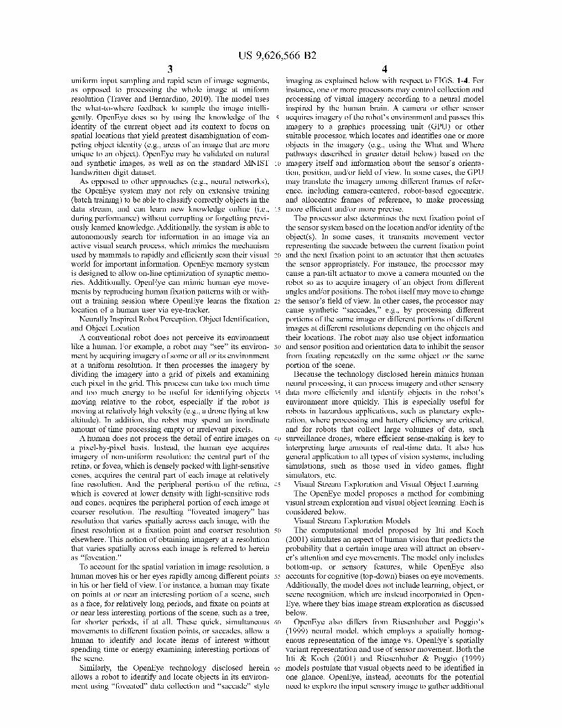
65 OpenEye is an artificial visual system operating on visualdata. The OpenEye model is comprised of four main mod-ules: the Environment Module, the Where system, the What
US 9,626,566 B27
system, and an external module that can provide a teachingsignal to the what system (FIG. 1). These four componentswill be discussed in detail below.The Environment Module (100) abstracts interactions
between the vision system and the environment, which canbe a virtual environment or a real environment sampled bya fix/pan-tilt camera, a robot-mounted camera, or othervisual (or non-visual) sensory system. This module deliversa visual image to the visual system and executes cameramovement commands, which emulate human eye move-ments. The environment module allows OpenEye to interactwith the environment: virtual or real, static or dynamic, realtime or prerecorded.One task of the Where System (130) is to decide where the
sensory system should look based on salient image proper-ties extracted from the visual image, or based on informationcoming from the What System pertaining to the identity ofobjects in the environments, and/or the scene identity as awhole. Processing of a visual image by the where systemmodule includes aspects of the mammalian lateral geniculatenucleus (LGN), primary visual cortex (VI), and highercortices (V2, MT, MST) processing. The image obtainedfrom the environment module in retinal coordinates under-goes a log-polar transformation to simulate space-variantsampling of the visual input and extraction of features suchas (but not limited to) edge, contour, color, and luminance.OpenEye's functioning is not limited to log-polar sampling,and can operate with other space-variant transformations,such as the reciprocal-wedge transform (Tong and Li, 1995),or the pyramid method (Adelson et. Al, 1984), as examples.
Also known as the dorsal stream in vision literature(Mishkin and Ungerleider 1982; Webster et al., 1994),OpenEye's Where System generates camera movements inorder sample an image by foveation on the spatial locationit selects as the most salient, where saliency can be deter-mined by sensory input or semantic (What System) infor-mation. Foveation is achieved by centering the sensor in theobject of interest, so that the object is likely to fall in thecenter of the space-variant representation. A form-fittingattentional shroud (namely a signal that fits the form, orshape, of an object, similarly to the way a shroud or veil fitsthe surface it rests on) is then formed around the foveatedobject. The shroud serves to suppress surrounding objects inorder to isolate the object of interest for learning in the WhatSystem, and enables the system to trigger further cameramovements centered exclusively on this enshrouded object.The ability of the Where System to form this attentionalshroud around a single object has the added benefit ofdetecting when a foveation has left the previous object ofinterest. This change in foveated object produces a resetsignal that represents temporal discontinuity between thefoveations and is used by the What System to regulatelearning, with the result of allowing OpenEye to groupmultiple views of an object (but not other objects, or thebackground) into coherent object categories. Another func-tion of the Where System is to maintain a visual workingmemory of previously foveated locations such that thecamera does not persistently choose the same point offixation. Together with the Environment Module, the WhereSystem forms the Where Pathway (140) that concerns withspatial interaction with the environment and spatial process-ing.The What System (150) includes a hierarchy of classifiers
that collectively learn to visually recognize an arbitrarynumber of objects regardless of each object's position andorientation relative to the sensor(s), e.g. a camera. The WhatSystem receives an object's feature representation as input
8from the Where System. Views are then clustered in anincremental, unsupervised fashion into object representa-tions based either on their similarity or according to theirtemporal continuity as signaled by the Where System. The
5 Where System provides a shroud-based reset signal, dis-cussed later, that informs the What System when seeminglydifferent views are part of the same or different object; thissignal is important to OpenEye's ability to learn pose-invariant object representations (Fazl et al., 2009). An
io optional external Teacher (160) provides a supervised learn-ing environment that not only improves classification accu-racy and learning speed but also dynamically creates auser-friendly search interface to the visual system's learnedknowledge. Because of the hierarchical separation of unsu-
15 pervised view learning and supervised object-label learning,the What System can be switched between unsupervised andsupervised learning modes at any time.The What system and Teacher together form the What
Pathway (170), modeled upon the ventral visual processing20 stream in the mammalian brain, which concerns the identity
of those objects viewed by OpenEye. FIG. 1 depicts theoverall structure of OpenEye. Each module is describedbelow with its corresponding block number.
Encoding OpenEye Activity25 A critical task for OpenEye operation is switching
between the coordinate systems centered on the on therobot/camera/sensor (ego-centric), the environment (image-centric or world-centric), and between metrics systems (e.g.,Cartesian or log-polar). For example, the image is sampled
30 using retinal (log-polar) metric, or other (e.g., pyramid orreciprocal-wedge), but the signal for the cameral to moveand how much to adjust the pitch, yaw is provided inCartesian (linear) metric. One role of the Where Systemconcerns translating between representations of a signal to
35 different coordinate bases. For clarity, each coordinate sys-tem is defined with a term that refers to where the system iscentered followed by a term that defines the distance metricof the reference frame. Reference frames can be centered atthree possible locations: 1) sensor-centered, 2) ego-centered,
4o and 3) image-centered. Sensor-centered refers to a coordi-nate system where the (0, 0) location resides at the positionof the current camera center. Ego-centered refers to acoordinate system where (0, 0) corresponds to a neutralposition of a sensor, with respect which the camera center
45 may be shifted or rotated. This robot-centered coordinatesystem can interface with other software systems to provideobject location data relative to the physical system or, whenpaired with global navigation data, to provide a global objectlocation. Image-centered refers to a reference frame in
50 which the (0, 0) location is at the image center. Image-centered can also be interpreted as global coordinates orscene-centered when the scene is dynamically changing.Correspondingly there are at least three set of dimensionsused in OpenEye: Image Dimensions [W, HJ, Sensor Move-
55 ment Range [We HJ, and Sensor Dimensions [WS HJ thatrepresent log-polar transform of the Sensor MovementRange. This notation is used in OpenEye description below.
There are at least two distance metrics in the coordinateframes: 1) log-polar, and 2) Cartesian. The log-polar dis-
60 tance metric reflects how the eye naturally samples theimage and image representation in primary visual cortex,and is employed in the described system by performing aspace-variant (log-polar in this case, but other methodscould be used) transformation to the ray input, while the
65 Cartesian distance metric is more pertinent when mappingrepresentations onto the real word or for invoking linearcontrol of the eye/camera. In the figures and text below,
US 9,626,566 B29
coordinate frame are referred to as a combination of whereit is centered and what defines its distance.
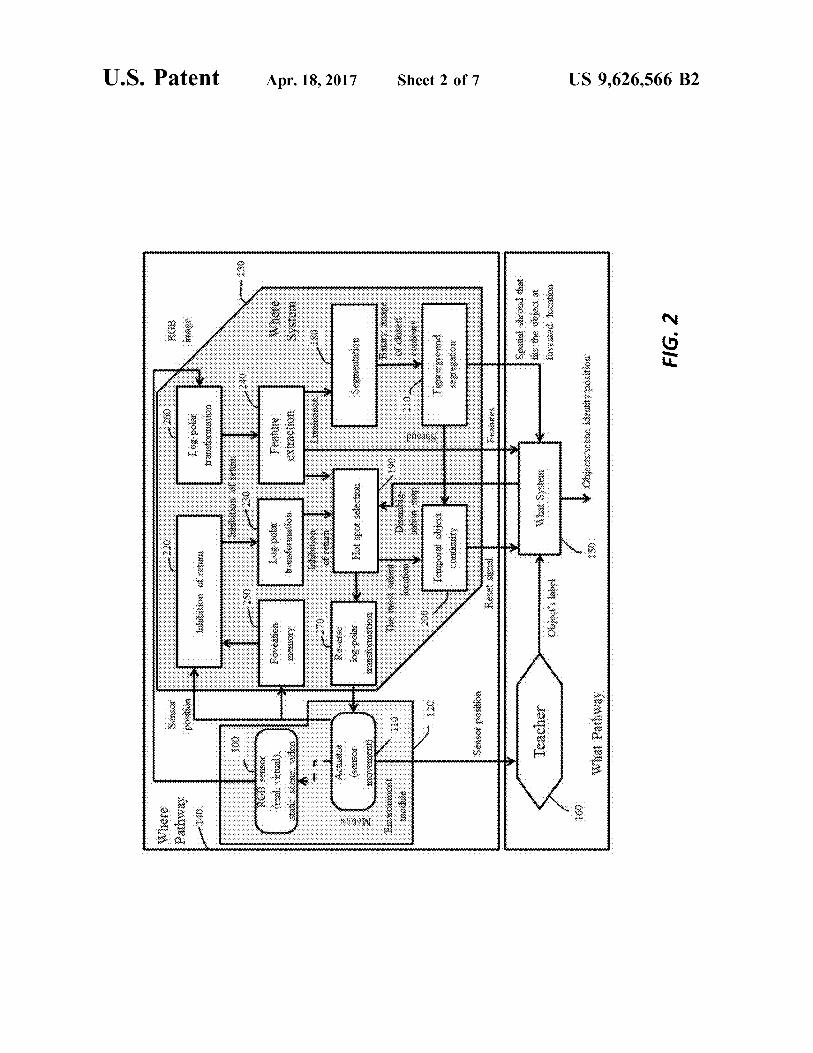
FIGS. 1-3 depicts aspects of the What and Where systemsof an example OpenEye system. FIG. 1 shows the Environ-ment Module (120) and the Where System (130), whichcollectively constitute the Where Pathway (140). The envi-ronment module 120 includes an RGB image sensor 100,which may acquire still and/or video images, whose field ofview can be shifted, narrowed, and/or expanded with one ormore actuators 110, including but not limited to zoomlenses, tip/tilt stages, translation stages, etc. The environ-ment module 120 provides both image data from the imagesensor 100 and actuation data (sensor position data) from theactuator(s) 110 to the Where system 130, which in turnprovides processed image data to the What system 150. Theenvironment module 120 also provides actuation data (sen-sor position data) from the actuator(s) 110 to the Teacher160, which forms part of the What pathway 170 with theWhat system 150.FIG. 2 shows the Where system 130 in greater detail. A
first log-polar transformation block 260 in the Where system130 performs a log-polar transformation on the image datafrom the image sensor 100 as described in greater detailbelow. A feature extraction block 240 identifies features inthe transformed image data, which is segmented intobounded regions by a segmentation block 180. A figure/segragation block 210 segregates the bounded regions toform a spatial shroud that fits the foveated region of theimage. The figure/segregation block 210 provides a repre-sentation of this spatial shroud to the What system 150.FIG. 2 also shows that the actuator(s) 100 provide sensor
position data to a foveation memory 250 and an inhibition ofreturn block 220, which together prevent the image sensorfrom foveating the same portions of the scene (acquiringand/or processing imagery of the same portions of the scene,e.g., at enhanced resolution) unnecessarily. A second log-polar transformation block 230 performs a log-polar trans-formation on the output of the inhibition of return block andpasses the transformed output to a hot spot selection block190, which determines the next portion of the scene forfoveation. A reverse log-polar transformation block 270transforms the output vector into the frame of reference usedby the actuator(s) 100 and provides the transformed outputvector to the actuator(s) 100 for actuation of the sensor 100.A temporal object continuity block 200 processes anothercopy of the hot spot selection block output to determine ifthe next foveation location falls off the current objectsurface. If so, the temporal object continuity block 200transmits a "reset" signal to the What system 150
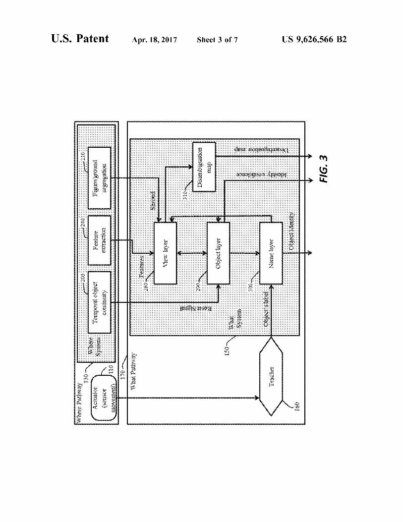
FIG. 3 shows the What system 150 in greater detail. TheWhat system 150 uses data from the temporal object con-tinuity block 200, the feature extraction block 240, and thefigure/ground segregation block 210 to identify and locateobjects in the scene imaged by the image sensor 100. A viewlayer 280 uses features and shroud data from the Wheresystem 130 to cluster shroud-gated visual representations ofobject views according to their feature similarity. A disam-biguation map block 310 generates a disambiguation map ofthe scene based on these representations from the view layer280.The object layer 290 uses the representations from the
view layer 280 to learn pose-invariant object representationsby associating different view prototypes from the view layer280 according to their temporal continuity provided by thereset signal from the Where system 130. This yields anidentity confidence measure, which can be fed into a namelayer 300 that groups different objects under the same user
10label, which may be obtained from an optional teacher 160.The optional teacher 160 shapes the association betweenobjects and their labels and feeds this information from theName layer 300 to the Object layer 290 and View layer 280
5 to the speed and accuracy of future object learning.The What system and the Where system can be imple-
mented in hardware, firmware, software, or a suitable com-bination thereof. For example, the What and Where systemsmay be implemented as processor-implementable instruc-
io tions that are stored in non-transient form in one or morememories located in or on a robot, such as a unmannedaerial, ground, or submersible vehicle. Some or all of theprocessor-implementable instructions may also be stored onremote memory, such memory in or accessible by a server
15 that communicates with the robot via a wireless communi-cation link (e.g., a radio-frequency or optical link).The robot may include one or more processors that are
coupled to the memory and configured to execute theinstructions so as to implement the What and Where sys-
20 tems, including the individual modules shown in FIGS. 1-4.For example, the robot may execute the instructions with acentral processing unit (CPU) and a graphics processing unit(GPU), e.g., as disclosed in U.S. Pat. No. 8,648,867, whichis incorporated herein by reference in its entirety. The
25 processor(s) can also be implemented as application specificintegrated circuits (ASICs), field-programmable gate arrays(FPGAs), and/or other device or component as understoodin the art.
In some embodiments, some or all of the processors mayso be located remotely that is, not on or in the robot. For
example, the processors (include GPUs) may be located inone or more smart phones, tablets, and/or single boardcomputers (SBCs). The processors may also form part or allof a cluster computing environment, with each processor in
35 the cluster dedicated to particular task or group of tasks. Inthese embodiments, the processors may communicate withsensors, actuators, and other devices and components on orin the robot via a suitable communications link, such as aradio-frequency or optical communications link.
40 FIG. 5 illustrates an OpenEye system 500 used to controla wheeled robot 510. The OpenEye system 500 includes acomputing device 504, such as a tablet computer or otherelectronic device with wireless capabilities, that is con-trolled by a user 502. The computing device 504 commu-
45 nicates with the robot 510, which includes an image sensor512 and an antenna 514, via a wireless link. The user 502issues commands to the robot 510 via software running onthe computing device 504, a processor (not shown) on therobot 510, and/or on other cloud-based processors (not
50 shown).In operation, the image sensor 512 can be oriented and/or
positioned either by the user when manually operating therobot or automatically by the software. For example, theimage sensor 512 may be mounted on a pan/tilt stage,
55 translation stage, or rotation stage that can be actuated tochange the image sensor's orientation and/or position. Theimage sensor 512 may also have a (motorized) zoom lensthat can be used to zoom in or out on certain portions of theenvironment. In addition, or instead, the image sensor 512
60 can be oriented or positioned as desired by moving the robot510. In some cases, the image sensor 512 may static withrespect to the robot 510; this is roughly equivalent tosomebody without, say, neck and eye muscles. In order tochange the static image sensor's point of view, the body of
65 the robot rotates and/or moves, e.g., using wheels or legs forground robots, propellers for drones, thrusters for submers-ible robots, etc.
US 9,626,566 B211 12
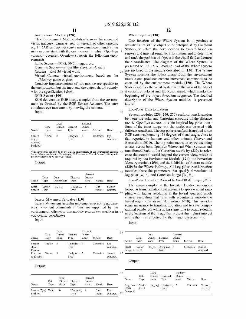
Environment Module (120) Where System (130)This Environment Module abstracts away the source of One function of the Where System is to produce a
visual imagery (cameras, real or virtual, or other sensors, foveated view of the object to be interpreted by the Whate.g. LIDAR) and applies sensor movement commands in the System, to select the next location to foveate based onmanner consistent with the environment in which OpenEye 5
sensory and internal semantic information, and to determinecurrently operates. OpenEye supports the following envi-
and track the position of objects in the visual field and returnronxnents:Static Scenes JPEG, PNG images, etc. their coordinates. The diagram of the Where System is
Dynamic Scenes movie files (.avi, .mp4, etc.) presented on FIG. 2. All modules part of the Where System
Camera Real 3d visual world 10 are enclosed in the module described in (130). The Where
Virtual Camera virtual environment, based on the System receives the video image from the environment
JMonkey game engine module and produces camera movement commands to be
Concrete implementations of this module are specific to executed by the environment module (120). The Where
the environment, but the input and the output should comply System supplies the What System with the view of the objectwith the specification below. 15 it currently looks at and the Reset signal, which marks theRGB Sensor (100) beginning of the object foveation sequence. The detailedRGB delivers the RGB image sampled from the environ- description of the Where System modules is presented
ment as directed by the RGB Sensor Actuator. The later below.simulates eye movement by moving the camera. Log-Polar Transformations
Input: 20Several modules (230, 260, 270) perform transformation
between log-polar and Cartesian encoding of the distance
Data Element metric. OpenEye adheres to a bio-inspired log-polar trans-Data Dimen- Element Dimen- form of the input image, but the model can be used with
Name Type sions Type sions Metric Base different transform. The log-polar transform is applied to the
Sensor Vector 0 Unsigned, 2 Cartesian Ego-
25
RGB sensor subtending 136 degrees of visual angle, close to(e.g., Byte centered that reported in humans and other animals (Traver andcamera) Bernardino, 2010). The log-polar metric in space encodingPosition* is used across both OpenEye Where and What Systems and
*This input does not have to be used in all environments. if the environment includes 30 transformed back to the Cartesian metric by (230) to refer-Sensor Movement actuator (for example, P&T camera, or Virtual Camera), this input is ence the external world beyond the current view, which isnot necessarily used by the RGB Sensor.
required by the Environment Module (120), the FoveationOutput: Memory module (250), and the Inhibition of Return module
(220) in the Where Pathway. All Log-polar transformation35 modules share the parameters that specify dimensions of
Element log-polar [ws hs] and Cartesian image [WS HS].Data Data Element Dimen-
Name Type Dimensions Type sions Metric Base Log-Polar Transformation of Retinal RGB Image (260)
RGB Vector [W,, H=] Unsigned, 3 Car- Sensor- The image sampled at the foveated location undergoesSensor Field Byte tesian centered log-polar transformation that amounts to space-variant sam-
40 pling with higher resolution in the foveal area and muchcoarser resolution that falls with eccentricity outside the
Sensor Movement Actuator (110)foveal region (Traver and Bernardino, 2010). This provides
Sensor Movement Actuator implements sensor (e.g., cam-some invariance to translation/rotation and to save compu-
era) movement commands if they are supported by thebandwidth while at the same time to acquire details
environment, otherwise this module returns eye position in 45
ego-centric coordinates.a th location of the image that present the highest interestat the
l
and is the most effective for the image representation.Input:
Input:
Data Element 50Data Dimen- Element Dimen- Data Element
Name Type sions Type sions Metric Base Data Dimen- Element Dimen-Name Type sions Type sions Metric Base
Sensor Vector 0 Unsigned, 2 Cartesian Ego-(Eye) Byte centered RGB Vector [W, HJ Unsigned, 3 Cartesian Sensor-Position Image I Field Byte centeredLocation Vector 0 Unsigned, 2 Cartesian Sensor- 55
to foveate Byte centered
Output:
Output:
60 Data ElementData Dimen- Element Dimen-
Data Element Name Type sions Type sions Metric BaseData Dimen- Element Dimen-
Name Type sions Type sions Metric Base Log-Polar Vector [w, h,] Unsigned, 3 Cartesian Sensor-RGB Field Byte centered
Sensor (Eye) Vector 0 Unsigned, 2 Car- Ego- Image OgPosition Byte tesian centered 65
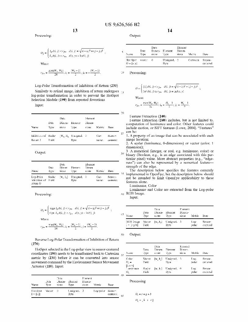
13Processing:
ljjd(i,j)<rfv d(i,j)= (i — io)_+(j— JO),
I yd(i, j) ? rf v d(x, y) = lnd(i, j)
Where:
max(W , Wh) . (Wh — 1) (WS — 1)rfv= 24 ;W= 2 ;Jo= — 2
US 9,626,566 B214
Output:
Data Element
5 Data Dimen- Element Dimen-
Name Type sions Type sions Metric Base
Hot Spot vector 0 Unsigned, 2 Cartesian Sensor-
0 = [x y] Byte centered
10 Processing:
Log-Polar Transformation of Inhibition of Return (230) 0- Uild(i, P<rf d(i, P= (i-iO) +(j - jo)2
Similarly to retinal image, inhibition of return undergoes 15 [xy]d(i, j) >- rf d(i, j) = 1nd(x, y)log-polar transformation in order to prevent the HotSpot
Where:Selection Module (190) from repeated foveations.
max(W , Wh) H, —1 W, —1Input: rf = 24 ; io = 2 ; jo = 2
Data Element
Data Dimen- Element Dimen-
Name Type sions Type sions Metric Base
Inhibition of Scalar [W, H,] Unsigned, 0 Car- Sensor-
Return I Field Byte tesian centered
Output:
Data Element
Data Dimen- Element Dimen-
Name Type sions Type sions Metric Base
Log-Polar Scalar [w, h,] Unsigned, 0 Car- Sensor-
inhibition of Field Byte tesian centered
return O
Processing:
20
Feature Extraction (240)Feature Extraction (240) includes, but is not limited to,
computation of luminance and color. Other features couldinclude motion, or SIFT features (Lowe, 2004). "Features"
25 can be:
1. A property of an image that can be associated with eachimage location;2. A scalar (luminance, 0-dimensions) or vector (color, Idimension);3. A numerical (integer, or real, e.g. luminance, color) or
30 binary (Boolean, e.g., is an edge associated with this par-ticular pixel) value. More abstract properties (e.g., "edge-ness") can also be represented by a numerical featurestrength of the edge.The description below specifies the features currently
35 implemented in OpenEye, but the description below shouldnot be intended to limit OpenEye applicability to thesefeatures alone.
Luminance, ColorLuminance and Color are extracted from the Log-polar
40 RGB Image.Input:
_ sign l d(i, j) < rf „ d (i, j) = (i — io)~ + (j — jo)20 i — ,
Data Element
sign I yd(i, j) >— rfv d(x, y) = lnd(i, J) 45Data Dimen- Element Dimen-
Name Type sions Type sions Metric Base
Where:RGB Image vector [w, h,] Unsigned, 3 Log- Sensor-
max(W , Wh) (Wh — 1) (W — 1) I= [r g b] Field Byte polar centeredrf = ;W=
2 ;j=24 2
50 Output:
Reverse Log-Polar Transformation of Inhibition of Return(270)
Data ElementHotSpot selected in the Log-polar view in sensor-centered Data Dimen- Element Dimen-
coordinates (190) needs to be transformed back to Cartesian 55 Name Type sions Type sions Metric Base
metric by (230) before it can be converted into sensor Color vector [w, h,] Unsigned, 3 Log- Sensor-
movement command by the Environment Sensor Movement O, = Field Byte polar centered
Actuator (110). Input: [h s v]Luminance Scalar [w, h,] Unsigned, 0 Log- Sensor-
OL Field Byte polar centered
60Data Element
Data Dimen- Element Dimen- Processing
Name Type sions Type sions Metric Base
Hot Spot Vector 0 Unsigned, 2 Log-polar Sensor-
I= [i ]] Byte centered 65 Oa = r + g + b
0,=[h s v]
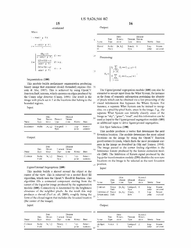
US 9,626,566 B215 16
-continued Output:
Where:
v = max(r g b ); Data Element
s 5 Data Dimen- Element Dimen-Name Type sions Type sions Metric Base
v—min(r g b)S= Shroud Scalar [w, hJ Binary, 0 Log- Sensor-
° O Field Byte polar centered
60(g — b)if v = r
v — min( r g b)10
Processing:120+60(b—r)
h— if v—min(r g b) g
240 + 60(r — g) I J Y, (l;J -- Ii-j—) > Ifv=bmin(r g b) i=—1,ql
15 i=—tA,rOij
O ) Yij -- Ii-j—) = I
Segmentation (180) j=-1,0,1
This module builds preliminary segmentation producingbinary image that represent closed (bounded) regions (Su- 20
zuki & Abe, 1985). This is achieved by using OpenCV The Figure/ground segregation module (180) can also befunction findContours, which operates on edges produced by extended to accept input from the What System, for instancethe Canny edge detector (Canny, 1986). The result is the in the form of semantic information pertaining the identityimage with pixels set to I at the locations that belong to the of pixels which can be obtained via a fast processing of thebounded regions. 25 visual information that bypasses the Where System. For
Input: instance, a separate What System can be trained to recog-nize, on a pixel-by-pixel basis, areas in the image. E.g., theseparate What System can initially classify areas of the
Data Element image as "sky", "grass", "road", and this information can beData Dimen- Element Dimen- 30 used as input to the Figure/ground segregation module (180)
Name Type sions Type sions Metric Base as additional input to drive figure/ground segregation.Luminance Scalar [w, hJ Unsigned, 0 Log- Sensor- Hot Spot Selection (190)
Byte polar centeredThis module produces a vector that determines the next
35 foveation location. The module determines the most salientOutput: locations on the image by using the OpenCV function
goodFeaturesToTrack, which finds the most prominent cor-ners in the image as described in (Shi and Tomasi, 1994).
Data Element The image passed to the corner finding algorithm is theData Dimen- Element Dimen-
Name Type sions Type sions Metric Base40
luminance feature produced by the feature extraction mod-ule (240). The Inhibition of Return signal produced by the
contours scalar [w= h=1 Binary, o Log- sensor- log-polar transformation module (23 0) disables the non-zeroField Byte polar centered
locations on the image to be selected as the next foveation
45 position.Figure/Ground Segregation (180) Input:This module builds a shroud around the object at the
center of the view. This is achieved via a seeded flood fillalgorithm, which uses the OpenCV floodFill function. This Data Element
algorithm fills a connected component starting from the 50Data Dimen- Element Dimen-
center of the log-polar image produced by the segmentationName Type sions Type sions Metric Base
module (180). Connectivity is determined by the brightness Contours Scalar [w= hJ Unsigned, 0 Log- Sensor-
closeness of the neighbor pixels. As the result this stepI Field Byte polar centeredInhibition of Scalar [w, hJ Binary, 0 Log- Sensor-
produces a shroud (Fazl et. all, 2009), roughly fitting the Return mask Field Byte polar centered
form of the closed region that includes the foveated location 55 I,
(the center of the image).
Input: Output:
60Data Element Data Element
Data Dimen- Element Dimen- Data Dimen- Element Dimen-Name Type sions Type sions Metric Base Name Type sions Type sions Metric Base
Contours Scalar [w, hJ Binary, 0 Log- Sensor- HotSpot Vector 0 Unsigned 2 Log- Sensor-I Field Byte polar centered 65 O Byte polar centered
US 9,626,566 B217
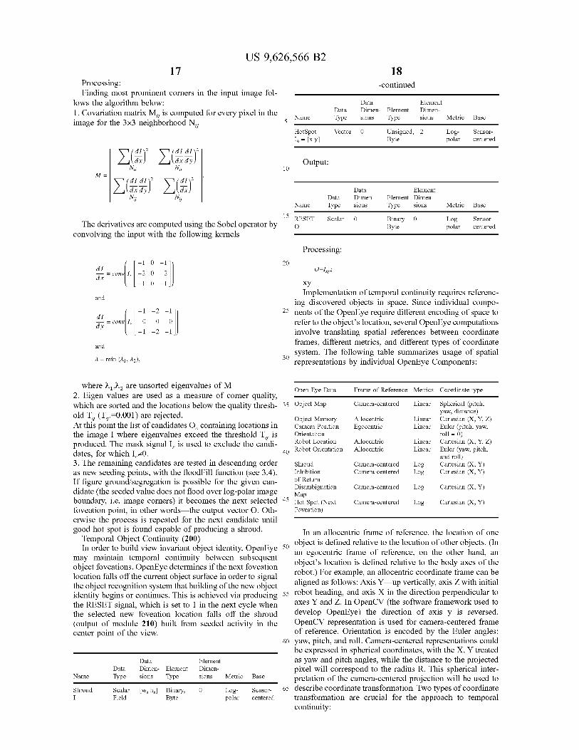
Processing:Finding most prominent corners in the input image fol-
lows the algorithm below:1. Covariation matrix MY is computed for every pixel in theimage for the 3x3 neighborhood NY
E(dx~
2
~j~TX- y~2N;ij Nij
M—
E(TX- y~2
X(dx~z
NU N;ij
The derivatives are computed using the Sobel operator byconvolving the input with the following kernels
dI 1 0 1
= conv~l, —2 0 —21 ~dx
1 0 1
and
dI
y= conv~l, 0 0 0
1 —2 1
and
A = min (fit, ;L2),
18-continued
Data ElementData Dimen- Element Dimen-
Name Type sions Type sions Metric Base5
HotSpot Vector 0 Unsigned, 2 Log- Sensor-I, = [x A Byte polar centered
Output:10
Data ElementData Dimen- Element Dimen-
Name Type sions Type sions Metric Base
15 RESET Scalar 0 Binary 0 Log- Sensor-o Byte polar centered
Processing:
20O=I,;
xyImplementation of temporal continuity requires referenc-
ing discovered objects in space. Since individual compo-25 nents of the OpenEye require different encoding of space to
refer to the object's location, several OpenEye computationsinvolve translating spatial references between coordinateframes, different metrics, and different types of coordinate
30 system. The following table summarizes usage of spatialrepresentations by individual OpenEye Components:
where XI IX2 are unsorted elgenvalues of M2. Eigen values are used as a measure of corner quality,
Open Eye Data Frame of Reference Metrics Coordinate type
which are sorted and the locations below the quality thresh- 35 Object Map Camera-centered Linear Spherical (pitch,
old T (T .-0.001) are rejected.T. qyaw' distance)
Object Memory Allocentric Linear Cartesian (X, Y, Z)At this point the list of candidates O, containing locations in Camera Position Egocentric Linear Enter (pitch, yaw,the image I where eigenvalues exceed the threshold Tq is orientation roll = 0)
produced. The mask signal I,, is used to exclude the candi- Robot Location Allocentric Linear Cartesian (X, y z)
dates, for which I0. 40 Robot Orientation Allocentric Linear Enter (yaw, pitch,
3. The remaining candidates are tested in descending orderand roll)
Shroud Camera-centered Log Cartesian (X, Y)as new seeding points, with the floodFill function (see 3.4). Inhibition Camera-centered Log Cartesian (X, Y)
If figure ground/segregation is possible for the given can- of Return
didate the seeded value does not flood over to olar image( g-p
gDisambiguation camera-centered Log Cartesian (X, y)
boundary, i.e. image corners) it becomes the next selectedMap
45 Hot Spot (Next Camera-centered Log Cartesian (X, Y)
foveation point, in other words the output vector O. Oth- Foveation)
erwise the process is repeated for the next candidate untilgood hot spot is found capable of producing a shroud. In an allocentric frame of reference, the location of one
Temporal Object Continuity (200)
50 object is defined relative to the location of other objects. (In
In order to build view invariant object identity, OpenEyean egocentric frame of reference, on the other hand, an
may maintain temporal continuity between subsequentobject's location is defined relative to the body axes of the
object foveations. OpenEye determines if the next foveationlocation falls off the current object surface in order to signal
robot.) For example, an allocentric coordinate frame can be
the object recognition system that building of the new object aligned as follows: Axis Y up vertically, axis Z with initial
identity begins or continues. This is achieved via producing 55 robot heading, and axis X in the direction perpendicular to
the RESET signal, which is set to I in the next cycle when axes Y and Z. In OpenCV (the software framework used to
the selected new foveation location falls off the shroud develop OpenEye) the direction of axis y is reversed.
(output of module 210) built from seeded activity in the OpenCV representation is used for camera-centered frame
center point of the view. of reference. Orientation is encoded by the Euler angles:60 yaw, pitch, and roll. Camera-centered representations could
be expressed in spherical coordinates, with the X, Y treated
Data Element as yaw and pitch angles, while the distance to the projectedData Dimen- Element Dimen- pixel will correspond to the radius R. This spherical inter-
Name Type sions Type sions Metric Base pretation of the camera-centered projection will be used to
Shroud Scalar [w, hJ Binary, 0 Log- Sensor- 65 describe coordinate transformation. Two types of coordinateI Field Byte polar centered transformation are crucial for the approach to temporal
continuity:
US 9,626,566 B219
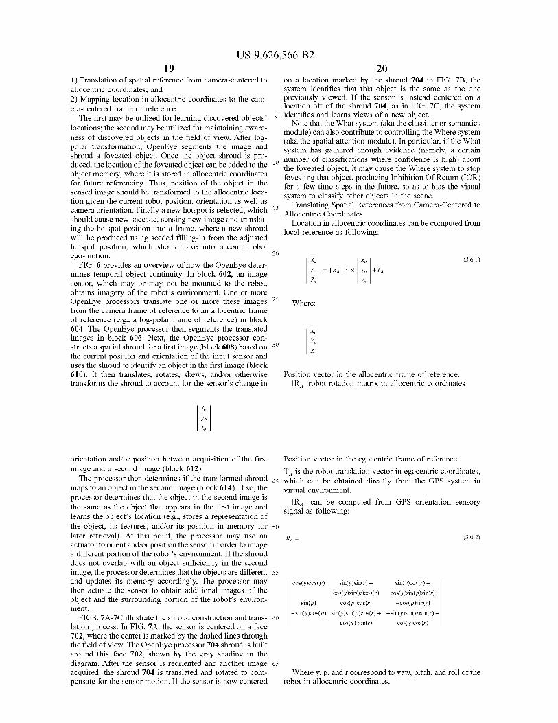
1) Translation of spatial reference from camera-centered toallocentric coordinates; and2) Mapping location in allocentric coordinates to the cam-era-centered frame of reference.The first may be utilized for learning discovered objects'
locations; the second may be utilized for maintaining aware-ness of discovered objects in the field of view. After log-polar transformation, OpenEye segments the image andshroud a foveated object. Once the object shroud is pro-duced, the location of the foveated object can be added to theobject memory, where it is stored in allocentric coordinatesfor future referencing. Thus, position of the object in thesensed image should be transformed to the allocentric loca-tion given the current robot position, orientation as well ascamera orientation. Finally a new hotspot is selected, whichshould cause new saccade, sensing new image and translat-ing the hotspot position into a frame, where a new shroudwill be produced using seeded filling-in from the adjustedhotspot position, which should take into account robotego-motion.
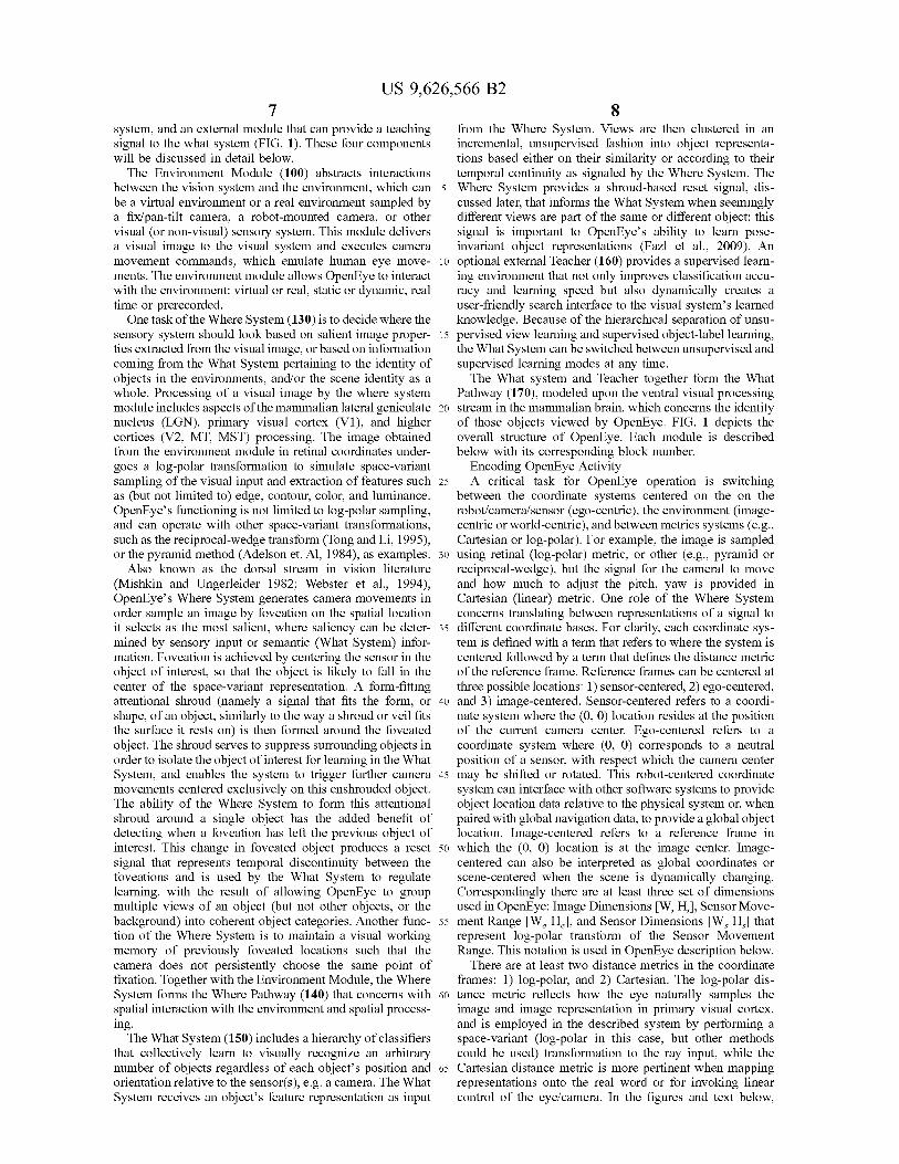
FIG. 6 provides an overview of how the OpenEye deter-mines temporal object continuity. In block 602, an imagesensor, which may or may not be mounted to the robot,obtains imagery of the robot's environment. One or moreOpenEye processors translate one or more these imagesfrom the camera frame of reference to an allocentric frameof reference (e.g., a log-polar frame of reference) in block604. The OpenEye processor then segments the translatedimages in block 606. Next, the OpenEye processor con-structs a spatial shroud for a first image (block 608) based onthe current position and orientation of the input sensor anduses the shroud to identify an object in the first image (block610). It then translates, rotates, skews, and/or otherwisetransforms the shroud to account for the sensor's change in
X,
Yo
Zo
orientation and/or position between acquisition of the firstimage and a second image (block 612).
The processor then determines if the transformed shroudmaps to an object in the second image (block 614). If so, theprocessor determines that the object in the second image isthe same as the object that appears in the first image andlearns the object's location (e.g., stores a representation ofthe object, its features, and/or its position in memory forlater retrieval). At this point, the processor may use anactuator to orient and/or position the sensor in order to imagea different portion of the robot's environment. If the shrouddoes not overlap with an object sufficiently in the secondimage, the processor determines that the objects are differentand updates its memory accordingly. The processor maythen actuate the sensor to obtain additional images of theobject and the surrounding portion of the robot's environ-ment.FIGS. 7A-7C illustrate the shroud construction and trans-
lation process. In FIG. 7A, the sensor is centered on a face702, where the center is marked by the dashed lines throughthe field of view. The OpenEye processor 704 shroud is builtaround this face 702, shown by the gray shading in thediagram. After the sensor is reoriented and another imageacquired, the shroud 704 is translated and rotated to com-pensate for the sensor motion. If the sensor is now centered
20on a location marked by the shroud 704 in FIG. 713, thesystem identifies that this object is the same as the onepreviously viewed. If the sensor is instead centered on alocation off of the shroud 704, as in FIG. 7C, the system
5 identifies and learns views of a new object.Note that the What system (aka the classifier or semantics
module) can also contribute to controlling the Where system(aka the spatial attention module). In particular, if the Whatsystem has gathered enough evidence (namely, a certain
10 number of classifications where confidence is high) aboutthe foveated object, it may cause the Where system to stopfoveating that object, producing Inhibition Of Return (IOR)for a few time steps in the future, so as to bias the visualsystem to classify other objects in the scene.
15 Translating Spatial References from Camera-Centered toAllocentric Coordinates
Location in allocentric coordinates can be computed fromlocal reference as following:
20Xo xo (3.6.1)
Yo = I RA 1-' X Yo +TA
Z1 zo
25Where:
xo
30 Y°0
Position vector in the allocentric frame of reference.IRA I robot rotation matrix in allocentric coordinates
Position vector in the egocentric frame of reference.
TA is the robot translation vector in egocentric coordinates,45 which can be obtained directly from the GPS system in
virtual environment.
IRA 1 can be computed from GPS orientation sensorysignal as following:
50
RA =
55
cos(y)cos(p) sin(y)sin(r) - sin(y)cos(r) +
cos(y)sin(p)cos(r) cos(y)sin(p)sin(r)
sin(p) cos(p)cos(r) -cos(p)sin(r)
-sin(y)cos(p) sin(y)sin(p)cos(r) + -sin(y)sin(p)sin(r) +60
cos(y) sin(r) cos(y)cos(r)
65
(3.6.2)
Where y, p, and r correspond to yaw, pitch, and roll of therobot in allocentric coordinates.
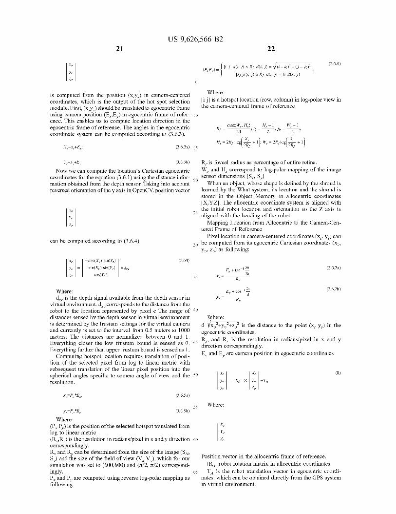
US 9,626,566 B221 22
xo
(P PY) _ [i ✓] d(i, J) < Rf d(i, J) _ (i — io)T + (J — Jo)
(3.6.6)
Yo [xy]d(i, j) >_ Rf d(i, ✓) = In d(x, y)
5
is computed from the position (xsys) in camera-centeredcoordinates, which is the output of the hot spot selectionmodule. First, (xsys) should be translated to egocentric frameusing camera position (E,,Ey) in egocentric frame of refer- 10ence. This enables us to compute location direction in theegocentric frame of reference. The angles in the egocentriccoordinate system can be computed according to (3.6.3).
X —x,+Ex;
Y =xy+Ey
(3.6.3a) 15
(3.6.3b)
Now we can compute the location's Cartesian egocentriccoordinates for the equation (3.6. 1) using the distance infor-mation obtained from the depth sensor. Taking into accountreversed orientation of the y axis in OpenCV, position vector
xo
Yo
Z,
can be computed according to (3.6.4)
xo —cos(X,) sin(Y,) (3.64)
Y, = —sin(X,) sin(Y,) x d y
Z COS(Y)
Where:
[i j] is a hotspot location (row, column) in log-polar view inthe camera-centered frame of reference
max(W,, H,) H,-1 W —1Rf= 24 ;io= 2 ;Jo= 2 ,
Sx H, = 2Rf lod 2Rf SY + 1); W, = 2Rflod 2Rf + 1~
Rf isfoveal radius as percentage of entire retina.
WS and HS correspond to log-polar mapping of the imagesensor dimensions (Sx, Sy)
20 When an object, whose shape is defined by the shroud is
learned by the What system, its location and the shroud isstored in the Object Memory in allocentric coordinates[X,Y,Z]. The allocentric coordinate system is aligned withthe initial robot location and orientation so the Z axis is
25 aligned with the heading of the robot.
Mapping Location from Allocentric to the Camera-Cen-tered Frame of Reference
Pixel location in camera-centered coordinates (xs, yJ can
30 be computed from its egocentric Cartesian coordinates (xo,yo, zo) as following:
E +tan' Yo
xo35 x,
Rx
(3.6.7a)
Where: Ey + cos-1 d
(3.6.7b)
d y is the depth signal available from the depth sensor in Y, = Ryvirtual environment. d y corresponds to the distance from therobot to the location represented by pixel c The range of 40
distances sensed by the depth sensor in virtual environment Where:is determined by the frustum settings for the virtual camera "~~
d=Vxo2+yo2+zo2 is the distance to the point (xs ys) in theand currently is set to the interval from 0.5 meters to 1000 egocentric coordinates.meters. The distances are normalized between 0 and 1. Rx, and Ry is the resolution in radians/pixel in x and yEverything closer the low frustum bound is sensed as 0. 45 direction correspondingly.Everything further than upper frustum bound is sensed as 1.
Computing hotspot location requires translation of posi-tion of the selected pixel from log to linear metric withsubsequent translation of the linear pixel position into thespherical angles specific to camera angle of view and the 50
xo xo (s)
resolution. Yo = I RA I ° -TA
Yo 0
x,=Px*Rx, (3.6.5a)
55y,—Py*Ry (3.6.5b)
Where:(Px Py) is the position of the selected hotspot translated fromlog to linear metric(Rx,Ry) is the resolution in radians/pixel in x and y direction 60correspondingly.Rx and Ry can be determined from the size of the image (SXSy) and the size of the field of view (Vx Vy), which for oursimulation was set to (600,600) and (7t/2, 7c/2) correspond-ingly. 65Px and Py are computed using reverse log-polar mapping asfollowing
Where:
Xo
Yo
0
Position vector in the allocentric frame of reference.
IRA 1 robot rotation matrix in allocentric coordinates
TA is the robot translation vector in egocentric coordi-nates, which can be obtained directly from the GPS systemin virtual environment.
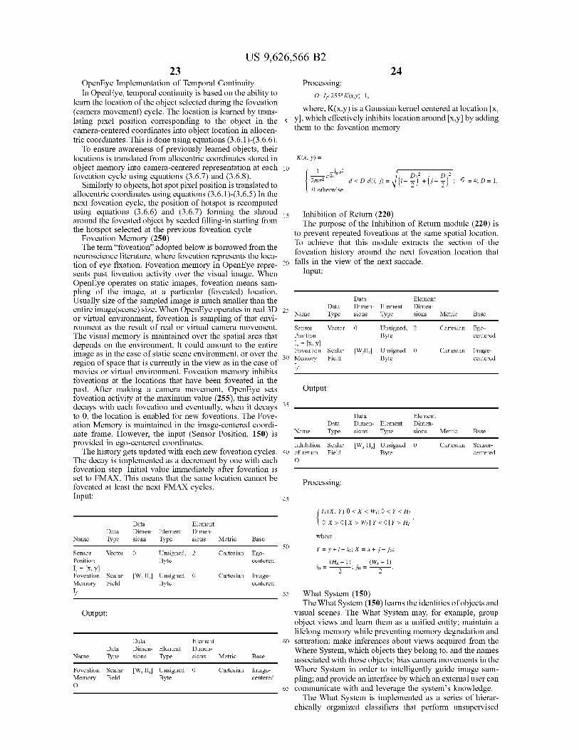
US 9,626,566 B223 24
OpenEye Implementation of Temporal Continuity Processing:In OpenEye, temporal continuity is based on the ability to 0-I+255*x(x y)-i,
learn the location of the object selected during the foveation(camera movement) cycle. The location is learned by trans- where, K(x,y) is a Gaussian kernel centered at location [x,
lating pixel position corresponding to the object in the 5 Y], which effectively inhibits location around [x,y] by adding
camera-centered coordinates into object location in allocen- them to the foveation memory
tric coordinates. This is done using equations (3.6.1)-(3.6.6).To ensure awareness of previously learned objects, their
locations is translated from allocentric coordinates stored in K(x, y) _object memory into camera-centered representation at each I 1 - d2foveation cycle using equations (3.6.7) and (3.6.8). e2,2 2
2io-2 d < D d(i, j) _ (i - 2)
+ j -
2~ 6 = 4; D = I.
Similarly to objects, hot spot pixel position is translated toallocentric coordinates using equations (3.6.1)-(3.6.5) In the
0 otherwise
next foveation cycle, the position of hotspot is recomputedusing equations (3.6.6) and (3.6.7) forming the shroud 15 Inhibition of Return (220)around the foveated object by seeded filling-in starting from The purpose of the Inhibition of Return module (220) isthe hotspot selected at the previous foveation cycle to prevent repeated foveations at the same spatial location.
Foveation Memory (250) To achieve that this module extracts the section of theThe term "foveation" adopted below is borrowed from the
foveation history around the next foveation location thatneuroscience literature, where foveation represents the loca-tion of eye fixation. Foveation memory in OpenEye repre- 20 falls in the view of the next saccade.
sents past foveation activity over the visual image. When Input:
OpenEye operates on static images, foveation means sam-pling of the image, at a particular (foveated) location.Usually size of the sampled image is much smaller than the Data Element
entire image(scene) size. When OpenEye operates in real 3D 25 Data Dimen- Element Dimen-
or virtual environment, foveation is sampling of that envi-
sions Metric Base
ronment as the result of real or virtual camera movement. Sensor vector 0 Unsigned, 2 Cartesian Ego-
The visual memory is maintained over the spatial area that Position Byte centereddepends on the environment. It could amount to the entire I= _ [X, Y]image as In the case Of static scene environment, OY over the
30Foveation Scalar [WiHi] Unsigned 0 Cartesian Image-
region of space that is currently in the view as in the case ofMemory Field Byte centeredIfmovies or virtual environment. Foveation memory inhibits
foveations at the locations that have been foveated in thepast. After making a camera movement, OpenEye sets Output:foveation activity at the maximum value (255), this activitydecays with each foveation and eventually, when it decays 35
to 0, the location is enabled for new foveations. The Fove- Data Elementation Memory is maintained in the image-centered coordi- Data Dimen- Element Dimen-
nate frame. However, the input (Sensor Position, 150) is Name Type sions Type sions Metric Base
provided in ego-centered coordinates. Inhibition Scalar [W, H,] Unsigned 0 Cartesian Sensor-The history gets updated with each new foveation cycles. 40 of return Field Byte centered
The decay is implemented as a decrement by one with each 0foveation step. Initial value immediately after foveation isset to FMAX. This means that the same location cannot be
Processing:foveated at least the next FMAX cycles.Input: 45
~If(X,Y) 0<X < WI; 0<Y<H,
Data Element 0 X > 0 X > W, I Y < 01 Y > H,
Data Dimen- Element Dimen-whereName Type sions Type sions Metric Base
Sensor Vector 0 Unsigned, 2 Cartesian Ego-Position Byte centeredI, _ [x, Y]Foveation Scalar [W, H,] Unsigned 0 Cartesian Image-Memory Field Byte centeredIf
Output:
Data ElementData Dimen- Element Dimen-
Name Type sions Type sions Metric Base
Foveation Scalar [W, H,] Unsigned 0 Cartesian Image-Memory Field Byte centered0
50 Y = =Y + i— W; X x + J — jo;
(HS-1) . (WS-1)io= 2 ;Jo= 2
55 What System (150)The What System (150) learns the identities of objects and
visual scenes. The What System may, for example, groupobject views and learn them as a unified entity; maintain alifelong memory while preventing memory degradation and
60 saturation; make inferences about views acquired from theWhere System, which objects they belong to, and the namesassociated with those objects; bias camera movements in theWhere System in order to intelligently guide image sam-pling; and provide an interface by which an external user can
65 communicate with and leverage the system's knowledge.The What System is implemented as a series of hierar-
chically organized classifiers that perform unsupervised
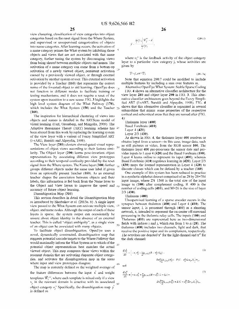
US 9,626,566 B225
view clustering, classification of view categories into objectcategories based on the reset signal from the Where System,and supervised or unsupervised categorization of objectsinto name categories. After learning occurs, the activation ofa name category primes the What system by inhibiting those 5objects and views that are not associated with that namecategory, further tuning the system by discouraging viewsfrom being shared between multiple objects and names. Theactivation of a name category can come from a bottom-up
10activation of a newly viewed object, persistent activation caused by a previously viewed object, or through externalactivation by another system or user. This external activationis provided by a Teacher (160) that represents the correctname of the foveated object to aid learning. OpenEye does 15not function in different modes to facilitate training ortesting mechanisms, and it does not require a reset of thesystem upon transition to a new scene. FIG. 3 highlights thehigh level system diagram of the What Pathway (170),which includes the What System (150) and the Teacher 20(160).
The inspiration for hierarchical clustering of views intoobjects and names is detailed in the ARTScan model ofvisual learning (Fazl, Grossberg, and Mingolla, 2009). TheAdaptive Resonance Theory (ART) learning scheme has 25been altered from this work by replacing the learning systemof the view layer with a variant of Fuzzy Simplified ART(F-BART; Baraldi and Alpaydin, 1998).
The View layer (280) clusters shroud-gated visual repre-sentations of object views according to their feature Simi- 30
larity. The Object layer (290) learns pose-invariant objectrepresentations by associating different view prototypesaccording to their temporal continuity provided by the resetsignal from the Where system. The Name layer (300) further 35groups different objects under the same user label if givenfrom an optionally present Teacher (160). As an externalteacher shapes the association between objects and theirlabels, this information is fed back from the Name layer tothe Object and View layers to improve the speed and 40accuracy of future object learning.
Disambiguation Map (310)This section describes in detail the Disambiguation Map
as introduced by Sherbakov et al. (2013a, b). A single inputview passed to the What System can activate multiple view, 45object, and name nodes. Although the output of each of theselayers is sparse, the system output can occasionally beunsure about object identity in the absence of an externalteacher. This is called "object ambiguity", as a single viewof an object can be associated with many objects. 50
To facilitate object disambiguation, OpenEye uses anovel, dynamically constructed, disambiguation map thatsuggests potential saccade targets to the Where Pathway thatwould maximally inform the What System as to which of the
55potential object representations best matches the actualviewed object. This map compares those views within theresonant domain that are activating disparate object catego-ries, and activates the disambiguation map in the areaswhere input and view prototypes disagree. 60The map is currently defined as the weighted average of
the feature differences between the input x and weight
templates W7x", where each template is mixed only if a viewvi in the resonant domain is coactive with its associated 65
object category oj" Specifically, the disambiguation map yis defined as
26
(280.7)Eo'VJ W —zJ
Y E0JVJ,
where oi" is the feedback activity of the object categorylayer to a particular view category j, whose activities aregiven by
, f (ff— ). (280.7a)
Note that equation 280.7 could be modified to includemultiple features by including a sum over features m.
Alternative OpenEye What System: Stable Sparse CodingFIG. 4 shows an alternative classifier architecture for the
view layer 280 and object layer 290 in FIG. 3. This alter-native classifier architecture goes beyond the Fuzzy Simpli-fied ART (f-BART; Baraldi and Alpaydin, 1998). FIG. 4shows that this alternative classifier is organized in severalsubmodules that mimic some properties of the respectivecortical and subcortical areas that they are named after (FIG.4):
Thalamus layer (400)Basal Forebrain (410)Layer 4 (420)Layer 2/3 (430).As shown in FIG. 4, the thalamus layer 400 receives or
obtains input from a sensor in this case, image data, suchas still pictures or video, from the RGB sensor 100. Thethalamus layer 400 pre-processes the sensor data and pro-vides inputs to Layer 4 (420) and the Basal Forebrain (100).Layer 4 learns online to represent its input (400), whereasBasal Forebrain (410) regulates learning in (420). Layer 2/3(430) maps the learned representation in Layer 4 (420) todiscrete classes which can be defined by a teacher (160)One example of this system has been reduced to practice
in a synthetic alphabet dataset comprised of an 28 by 28=784input image, where 2N=1568 is the total size of the inputimage in (100) after complement coding, R=400 is thenumber of coding cells (410), and M=26 is the size of layer2/3 (430).
Thalamus (400)Unsupervised learning of a sparse encoder occurs in the
synapses between thalamus (400) and Layer 4 (410). Thesensor input, I, is processed through (400) as a shuntingnetwork, x, intended to represent the on-center off-surroundprocessing in the thalamic relay cells. The inputs (100) andThalamus (400) are represented here as two-dimensionalfields with indices i and j, which run from 1 to n (28). Thethalamus (400) includes two channels, light and dark, thatreceive the positive input and its complement, respectively.The activities are denoted xL for the light channel and xD forthe dark channel:
dx (1)
dt —[—axxj+Egi,J,k,d(B—XiLj)(Ikd)ki
DxjEh;, J,k,a (xka) + E(C — XL)Ewj,Y,]1T_
and
d x° (2)
dt —axxp+ES;,i,k,a(B—~)(1-41)—
Dx°Ehi J,k,t (xkDJ) + E(C — x°)Ew;J,Y,]1,_
US 9,626,566 B227
where ax-0.4, B=1, C=-0.1, D-0.05, E-0.15, T,-6 and gis a Gaussian function of the difference between i and kcentered around 0 (mean) with a width of 0.4 (the standarddeviation), h is a likewise function of a width 2.8. Theparameter C corresponds to a hyperpolarization value.
Basal Forebrain (410)
The basal forebrain includes a single cell (b, a) whichresponds to fluctuations in the activities of thalamic cells(400) from both channels:
d b i (3)
dt ii --b+GEIN
x~ITb, and
28Excitability homeostasis occurs at Layer 4 (y, Y) neurons
by adaptive thresholds (t):
5 dti _ (Y.-P)(Cra+OT)dt Tt
where Ct 0.6, 0T-0.3, tit 1/0.06, and p is the sparsenessparameter, set to 0.05. The values for t~ are set to random
10 values uniformly chosen from the range 0.5 to 2.3. Thelearning from Thalamic neurons (x, 400) to Layer 4 neurons(y, Y, 420) is governed by:
x"xii (4) 15 w"r =;W I xi I -w;i.)Y.)1-r ,a= ~+ GEx"-b +HEI - — -V dti2N i N
(12)
where ti,,.~= 384. The lateral inhibition (q) at Layer 4 (y, Y)where G=2, V-0.00001, H=1.8, Tb=1/0.131 Ea-0.009, is adaptive (an "anti-Hebbian" law):
and a represents the cholinergic signal. The function 1 is a 20
threshold linear function that nullifies all negative values:
t= -;L(Y,Y, - P')ITg, .
(13)
u, U> 0 (5)
25{l 0, u <- 0 where tiq 167. The learning rate X is a function of thestrength of feedback and the ratio of cholinergic modulation:
This cholinergic signal drives a slower signal that bio-logically might correspond to muscarinic receptor activa- 30tion:
da - -a+Ja and (6)
dt - Ta
a = I(a) + C, (7)
4Ew; Y, a
A=E 2N -1 +Cxa +CA,
(14)
where L-0.12, C,-0.04, and E,-0.005.Layer 2/3 (430)
35 In this system, supervised learning of visual categoriesoccurs in the synapses between later 4 (420) and layer 2/3(430). Specifically, layer 2/3 neurons (z, 430) use a variantof the recurrent shunting on-center off-surround network:
where 7-0.9, TQ 20, and EQ-0.001.
Layer 4 (420) 40
The activities at cortical coding cells in layer 4 (y)fluctuate based on their thalamic input (x), lateral inhibitionand modulation (420):
45
Yr
dt-[fy(-t,+Ew;i, xi +Ei.y,)-y,(Cya+ay)1/Ty,
(8)
where Cy 3. 1, ay, -0.001, and by 2.5. The signal functionis a logistic function:
1 (9)fy(u) =
1 + - PyW
(15)ITz d =-azZm+(B-Zm) m+fz(Zm)+RY.._Y, -
Z.LGz0 - m)+Y,f (Zk)J.
where oL -0.2, B=1, Tz 1/0.75, Dz 120, C -0.1 and T isthe aforementioned supervision, or Teacher (160), vector
50 (i.e. the truth or target output). The supervision, therefore,acts as an input to the Layer 2/3 cells. It does not directlyappear in the synaptic learning law. In this way, the fullcircuit is stackable in a hierarchical way. Higher corticalareas can simply send feedback that acts as this supervision
55 signal. The signal function is a logistic function:
where (3y 30. Layer 4 cortical activity must exceed athreshold before it affects learning or it is transmitted backto thalamus: 60
1, y, >- 0.5 (10)Yr = 0, y, < 0.5
65
f (u) = 1 + ,6z(,z)(16)
where az-0.65 and (3y15, and corresponds to slope andthreshold, respectively. The learning from Layer 4 neurons(y, Y) to Layer 2/3 neurons (z) is governed by:
d&)_T~
dt
(17)
US 9,626,566 B229
-continued
Y 2
(R -.—)f(zm)~£~ -,Ef(zk)~ +w.m~&-Y,wmzm~
LLL r
where X.—O.6, P.—O.04 (400*0.0001), T.-1/0.002, andEw_0.001.
CONCLUSION
While various inventive embodiments have beendescribed and illustrated herein, those of ordinary skill in theart will readily envision a variety of other means and/orstructures for performing the function and/or obtaining theresults and/or one or more of the advantages describedherein, and each of such variations and/or modifications isdeemed to be within the scope of the inventive embodimentsdescribed herein. More generally, those skilled in the art willreadily appreciate that all parameters, dimensions, materials,and configurations described herein are meant to be exem-plary and that the actual parameters, dimensions, materials,and/or configurations will depend upon the specific appli-cation or applications for which the inventive teachingsis/are used. Those skilled in the art will recognize, or be ableto ascertain using no more than routine experimentation,many equivalents to the specific inventive embodimentsdescribed herein. It is, therefore, to be understood that theforegoing embodiments are presented by way of exampleonly and that, within the scope of the appended claims andequivalents thereto, inventive embodiments may be prac-ticed otherwise than as specifically described and claimed.Inventive embodiments of the present disclosure are directedto each individual feature, system, article, material, kit,and/or method described herein. In addition, any combina-tion of two or more such features, systems, articles, mate-rials, kits, and/or methods, if such features, systems, articles,materials, kits, and/or methods are not mutually inconsis-tent, is included within the inventive scope of the presentdisclosure.The above-described embodiments can be implemented
in any of numerous ways. For example, embodiments ofdesigning and making the technology disclosed herein maybe implemented using hardware, software or a combinationthereof. When implemented in software, the software codecan be executed on any suitable processor or collection ofprocessors, whether provided in a single computer or dis-tributed among multiple computers.
Further, it should be appreciated that a computer may beembodied in any of a number of forms, such as a rack-mounted computer, a desktop computer, a laptop computer,or a tablet computer. Additionally, a computer may beembedded in a device not generally regarded as a computerbut with suitable processing capabilities, including a Per-sonal Digital Assistant (PDA), a smart phone or any othersuitable portable or fixed electronic device.
Also, a computer may have one or more input and outputdevices. These devices can be used, among other things, topresent a user interface. Examples of output devices that canbe used to provide a user interface include printers or displayscreens for visual presentation of output and speakers orother sound generating devices for audible presentation ofoutput. Examples of input devices that can be used for a userinterface include keyboards, and pointing devices, such asmice, touch pads, and digitizing tablets. As another example,a computer may receive input information through speechrecognition or in other audible format.
30Such computers may be interconnected by one or more
networks in any suitable form, including a local area net-work or a wide area network, such as an enterprise network,and intelligent network (IN) or the Internet. Such networks
5 may be based on any suitable technology and may operateaccording to any suitable protocol and may include wirelessnetworks, wired networks or fiber optic networks.The various methods or processes outlined herein may be
coded as software that is executable on one or more pro-io cessors that employ any one of a variety of operating
systems or platforms. Additionally, such software may bewritten using any of a number of suitable programminglanguages and/or programming or scripting tools, and alsomay be compiled as executable machine language code or
15 intermediate code that is executed on a framework or virtualmachine.In this respect, various inventive concepts may be embod-
ied as a computer readable storage medium (or multiplecomputer readable storage media) (e.g., a computer memory,
20 one or more floppy discs, compact discs, optical discs,magnetic tapes, flash memories, circuit configurations inField Programmable Gate Arrays or other semiconductordevices, or other non-transitory medium or tangible com-puter storage medium) encoded with one or more programs
25 that, when executed on one or more computers or otherprocessors, perform methods that implement the variousembodiments of the invention discussed above. The com-puter readable medium or media can be transportable, suchthat the program or programs stored thereon can be loaded
30 onto one or more different computers or other processors toimplement various aspects of the present invention as dis-cussed above.The terms "program" or "software" are used herein in a
generic sense to refer to any type of computer code or set of35 computer-executable instructions that can be employed to
program a computer or other processor to implement variousaspects of embodiments as discussed above. Additionally, itshould be appreciated that according to one aspect, one ormore computer programs that when executed perform meth-
40 ods of the present invention need not reside on a singlecomputer or processor, but may be distributed in a modularfashion amongst a number of different computers or pro-cessors to implement various aspects of the present inven-tion.
45 Computer-executable instructions may be in many forms,such as program modules, executed by one or more com-puters or other devices. Generally, program modules includeroutines, programs, objects, components, data structures,etc. that perform particular tasks or implement particular
50 abstract data types. Typically the functionality of the pro-gram modules may be combined or distributed as desired invarious embodiments.
Also, data structures may be stored in computer-readablemedia in any suitable form. For simplicity of illustration,
55 data structures may be shown to have fields that are relatedthrough location in the data structure. Such relationshipsmay likewise be achieved by assigning storage for the fieldswith locations in a computer-readable medium that conveyrelationship between the fields. However, any suitable
60 mechanism may be used to establish a relationship betweeninformation in fields of a data structure, including throughthe use of pointers, tags or other mechanisms that establishrelationship between data elements.
Also, various inventive concepts may be embodied as one65 or more methods, of which an example has been provided.
The acts performed as part of the method may be ordered inany suitable way. Accordingly, embodiments may be con-
US 9,626,566 B231
structed in which acts are performed in an order differentthan illustrated, which may include performing some actssimultaneously, even though shown as sequential acts inillustrative embodiments.
All definitions, as defined and used herein, should beunderstood to control over dictionary definitions, definitionsin documents incorporated by reference, and/or ordinarymeanings of the defined terms.The indefinite articles "a" and "an," as used herein in the
specification and in the claims, unless clearly indicated tothe contrary, should be understood to mean "at least one."The phrase "and/or," as used herein in the specification
and in the claims, should be understood to mean "either orboth" of the elements so conjoined, i.e., elements that areconjunctively present in some cases and disjunctively pres-ent in other cases. Multiple elements listed with "and/or"should be construed in the same fashion, i.e., "one or more"of the elements so conjoined. Other elements may optionallybe present other than the elements specifically identified bythe "and/or" clause, whether related or unrelated to thoseelements specifically identified. Thus, as a non-limitingexample, a reference to "A and/or B", when used in con-junction with open-ended language such as "comprising"can refer, in one embodiment, to A only (optionally includ-ing elements other than B); in another embodiment, to Bonly (optionally including elements other than A); in yetanother embodiment, to both A and B (optionally includingother elements); etc.As used herein in the specification and in the claims, "or"
should be understood to have the same meaning as "and/or"as defined above. For example, when separating items in alist, "or" or "and/or" shall be interpreted as being inclusive,i.e., the inclusion of at least one, but also including morethan one, of a number or list of elements, and, optionally,additional unlisted items. Only terms clearly indicated to thecontrary, such as "only one of or "exactly one of," or, whenused in the claims, "consisting of," will refer to the inclusionof exactly one element of a number or list of elements. Ingeneral, the term "or" as used herein shall only be inter-preted as indicating exclusive alternatives (i.e. "one or theother but not both") when preceded by terms of exclusivity,such as "either," "one of," "only one of," or "exactly one of.""Consisting essentially of," when used in the claims, shallhave its ordinary meaning as used in the field of patent law.As used herein in the specification and in the claims, the
phrase "at least one," in reference to a list of one or moreelements, should be understood to mean at least one elementselected from any one or more of the elements in the list ofelements, but not necessarily including at least one of eachand every element specifically listed within the list ofelements and not excluding any combinations of elements inthe list of elements. This definition also allows that elementsmay optionally be present other than the elements specifi-cally identified within the list of elements to which thephrase "at least one" refers, whether related or unrelated tothose elements specifically identified. Thus, as a non-limit-ing example, "at least one of A and B" (or, equivalently, "atleast one of A or B," or, equivalently "at least one of A and/orB") can refer, in one embodiment, to at least one, optionallyincluding more than one, A, with no B present (and option-ally including elements other than B); in another embodi-ment, to at least one, optionally including more than one, B,with no A present (and optionally including elements otherthan A); in yet another embodiment, to at least one, option-ally including more than one, A, and at least one, optionallyincluding more than one, B (and optionally including otherelements); etc.
32In the claims, as well as in the specification above, all
transitional phrases such as "comprising," "including," "car-rying," "having," "containing," "involving," "holding,""composed of," and the like are to be understood to be
5 open-ended, i.e., to mean including but not limited to. Onlythe transitional phrases "consisting of and "consistingessentially of shall be closed or semi-closed transitionalphrases, respectively, as set forth in the United States PatentOffice Manual of Patent Examining Procedures, Section
10 2111.03.
REFERENCES
15The following references are incorporated herein by ref-
erence in their respective entireties:Adelson, E. H., Anderson, C. H., Bergen, J. R., Burt, P. J.,& Ogden, J. M. (1984). Pyramid methods in imageprocessing. RCA engineer, 29(6), 33-41.
20 Baraldi, A. and Alpaydin, E. (1998). Simplified ART: Anewclass of ART algorithms. International Computer ScienceInstitute, Berkeley, Calif., TR-98-004, 1998.
Baraldi, A. and Alpaydin, E. (2002). Constructive feedfor-ward ART clustering networks Part I. IEEE Transac-
25 tions on Neural Networks 13(3), 645-661.Baraldi, A. and Parmiggiani, F. (1997). Fuzzy combinationof Kohonen's and ART neural network models to detectstatistical regularities in a random sequence of multi-valued input patterns. In International Conference on
30 Neural Networks, IEEE.Bengio, Y., Courville, A., & Vincent, P. (2013). Represen-
tation learning: A review and new perspectives.Besl, P. J., & Jain, R. C. (1985). Three-dimensional object
recognition. ACM Computing Surveys (CSUR), 17(1),35
75-145.Bradski, G., & Grossberg, S. (1995). Fast-learningVIEWNET architectures for recognizing three-dimen-sional objects from multiple two-dimensional views. Neu-
40 ral Networks, 8 (7-8), 1053-1080.Canny, J., A (1986) Computational Approach To Edge
Detection, IEEE Trans. Pattern Analysis and MachineIntelligence, 8(6):679-698. Carpenter, G. A. and Gross-berg, S. (1987). A massively parallel architecture for a
45 self-organizing neural pattern recognition machine. Com-puter Vision, Graphics, and Image Processing 37, 54-115.
Carpenter, G. A., & Grossberg, S. (1987). A massivelyparallel architecture for a self-organizing
Carpenter, G. A., and Grossberg, S. (1995). Adaptive reso-50 nance theory (ART). In M. Arbib (Ed.), The handbook of
brain theory and neural networks. (pp. 79-82). Cam-bridge, M. A.: MIT press.
Carpenter, G. A., Grossberg, S. and Rosen, D. B. (1991).Fuzzy ART: Fast stable learning and categorization of
55 analog patterns by an adaptive resonance system. NeuralNetworks 4, 759-771.
Dosher, B. A., and Lu, Z. L. (2010). Mechanisms of per-ceptual attention in precuing of location. Vision Res.,40(10-12). 1269-1292.
6o Fazl, A., Grossberg, S., and Mingolla, E. (2009). View-invariant object category learning, recognition, andsearch: How spatial and object attention are coordinatedusing surface-based attentional shrouds. Cognitive Psy-chology 58, 1-48.
65 F61diak, P. (1990). Forming sparse representations by localanti-Hebbian learning, Biological Cybernetics, vol. 64,pp. 165-170.
US 9,626,566 B233
Friston K., Adams R., Perrinet L., & Breakspear M. (2012).Perceptions as hypotheses: saccades as experiments.Frontiers in Psychology, 3 (151), 1-20.
Geiger A, Lenz P, and Urtasun R (2012). Are we ready forautonomous driving? The KITTI vision benchmark suite. 5
In Computer Vision and Pattern Recognition (CVPR),Providence, USA.
George, D. and Hawkins, J. (2009). Towards a mathematicaltheory of cortical micro-circuits. PLoS ComputationalBiology 5(10), 1-26.
10
Grossberg, S. (1973). Contour enhancement, short-termmemory, and constancies in reverberating neural net-works. Studies in Applied Mathematics 52, 213-257.
Grossberg, S., and Huang, T. R. (2009). ARTSCENE: A 15neural system for natural scene classification. Journal ofVision, 9 (4), 6.1-19. doi:10.1167/9.4.6
Grossberg, S., and Versace, M. (2008) Spikes, synchrony,and attentive learning by laminar thalamocortical circuits.Brain Research, 1218C, 278-312 [Authors listed alpha- 20betically] .
Hinton, G. E., Osindero, S., and Teh, Y. (2006). A fastlearning algorithm for deep belief nets. Neural Compu-tation, 18, 1527-1554.
Itti, L., and Koch, C. (2001). Computational modelling of 25
visual attention. Nature Reviews Neuroscience, 2 (3),194-203.
Itti, L., Koch, C., and Niebur, E. (1998). A Model ofSaliency-Based Visual Attention for Rapid Scene Analy-sis, 1-6. 30
Jarrett, K., Kavukcuoglu, K., Ranzato, M. A., & LeCun, Y.(2009, September). What is the best multi-stage architec-ture for object recognition?. In Computer Vision, 2009IEEE 12th International Conference on (pp. 2146-2153). 35IEEE.
Kowler, E. (2011). Eye movements: The past 25 years.Vision Research, 51(13), 1457-1483. doi:10.1016/j .visres.2010.12.014
Larochelle H., & Hinton G. (2012). Learning to combine 40foveal glimpses with a third-order Boltzmann machine.NIPS 2010, 1243-1251.
LeCun, Y., Kavukcuoglu, K., & Farabet, C. (2010, May).Convolutional networks and applications in vision. InCircuits and Systems (ISCAS), Proceedings of 2010 IEEE 45International Symposium on (pp. 253-256). IEEE.
Lee, D. D. and Seung, H. S. (1999). Learning the parts ofobjects by non-negative matrix factorization. Nature, 401(6755):788-791.
Lee, D. D., and Seung, H. S. (1997). "Unsupervised learning 50by convex and conic coding." Advances in Neural Infor-mation Processing Systems, 9.
Lowe, D. G. (2004). Distinctive Image Features from Scale-Invariant Keypoints. Journal International Journal ofComputer Vision archive Volume 60, 2, 91-110. 55
Lu, Z. L., Liu, J., and Dosher, B. A. (2010) Modelingmechanisms of perceptual learning with augmented Heb-bian re-weighting. Vision Research, 50(4). 375-390.
Mishkin M, Ungerleider L G. (1982). "Contribution ofstriate inputs to the visuospatial functions of parieto- 60preoccipital cortex in monkeys," Behav Brain Res, 6 (1):57-77.
Najemnik, J., and Geisler, W. (2009). Simple summationrule for optimal fixation selection in visual search. VisionResearch. 49, 1286-1294. 65
neural pattern-recognition machine. Computer VisionGraphics and Image Processing, 37 (1), 54-115.
34Oja, E. (1982). Simplified neuron model as a principalcomponent analyzer. Journal of Mathematical Biology15(3), 267-273.
Pessoa L, Thompson E, and NoeA (1998). Finding out aboutfilling-in: A guide to perceptual completion for visualscience and the philosophy of perception. Behavioral andBrain Sciences 21(6), 723-748.
Raijmakers, M. E. J., and Molenaar, P. (1997). Exact ART:A complete implementation of an ART network Neuralnetworks 10 (4), 649-669.
Ranzato, M. A., Huang, F. J., Boureau, Y. L., & Lecun, Y.(2007, June). Unsupervised learning of invariant featurehierarchies with applications to object recognition. InComputer Vision and Pattern Recognition, 2007.CVPR'07. IEEE Conference on (pp. 1-8). IEEE.
Riesenhuber, M., & Poggio, T. (1999). Hierarchical modelsof object recognition in cortex. Nature Neuroscience, 2(11), 1019-1025.
Riesenhuber, M., & Poggio, T. (2000). Models of objectrecognition. Nature neuroscience, 3, 1199-1204.
Rublee E, Rabaud V, Konolige K, and Bradski G (2011).ORB: An efficient alternative to SIFT or SURF. In IEEEInternational Conference on Computer Vision (ICCV),2564-2571.
Rublee, E., Rabaud, V., Konolige, K., & Bradski, G. (2011).ORB: An efficient alternative to SIFT or SURF. In IEEEInternational Conference on Computer Vision (ICCV)2011, 2564-2571.
Rumelhart D., Hinton G., and Williams, R. (1986). Learninginternal representations by error propagation. In Paralleldistributed processing: explorations in the microstructureof cognition, vol. 1, MIT Press.
Russell B, Torralba A, Murphy K, and Freeman W T (2008).LabelMe: A database and web-based tool for imageannotation. International Journal of Computer Vision77(1-3), 157-173.
Salakhutdinov, R., & Hinton, G. E. (2009). Deep boltzmannmachines. In International Conference on Artificial Intel-ligence and Statistics (pp. 448-455).
Seibert, M., & Waxman, A. M. (1992). Adaptive 3-D ObjectRecognition from Multiple Views. IEEE Transactions onPattern Analysis and Machine Intelligence, 14 (2), 107-124.
Sherbakov, L., Livitz, G., Sohail, A., Gorchetchnikov, A.,Mingolla, E., Ames, H., and Versace, M. (2013a) CogEye:An online active vision system that disambiguates andrecognizes objects. NeuComp 2013.
Sherbakov, L., Livitz, G., Sohail, A., Gorchetchnikov, A.,Mingolla, E., Ames, H., and Versace, M (2013b) Acomputational model of the role of eye-movements inobject disambiguation. Cosyne, Feb. 28-Mar. 3, 2013. SaltLake City, Utah, USA.
Smolensky, P. (1986). Information processing in dynamicalsystems: Foundations of harmony theory. In D. E. Rumel-hartand J. L. McClelland, editors, Parallel DistributedProcessing, volume 1, chapter 6, pages 194-281. MITPress, Cambridge.
Spratling, M. W. (2008). Predictive coding as a model ofbiased competition in visual attention. Vision Research,48(12):1391-1408.
Spratling, M. W. (2012). Unsupervised learning of genera-tive and discriminative weights encoding elementaryimage components in a predictive coding model of cor-tical function. Neural Computation, 24(1): 60-103.
US 9,626,566 B235
Spratling, M. W., De Meyer, K., and Kompass, R. (2009).Unsupervised learning of overlapping image componentsusing divisive input modulation. Computational intelli-gence and neuroscience.
Tong, F., Ze-Nian Li, (1995). Reciprocal-wedge transformfor space-variant sensing," Pattern Analysis and MachineIntelligence, IEEE Transactions on, vol. 17, no. 5, pp.500-51. doi: 10.1109/34.391393
Torralba, A., Oliva, A., Castelhano, M. S., Henderson, J. M.(2006). Contextual guidance of eye movements and atten-tion in real-world scenes: the role of global features inobject search. Psychological Review, 113(4).766-786.
Versace, M. (2006) From spikes to interareal synchrony:how attentive matching and resonance control learningand information processing by laminar thalamocorticalcircuits. NSF Science of Learning Centers PI Meeting,Washington, D.C., USA.
Webster, Bachevalier, Ungerleider (1994). Connections ofIT areas TEO and TE with parietal and frontal cortex inmacaque monkeys. Cerebal Cortex, 4(5), 470-483.
The invention claimed is:1. A system comprising:an image sensor to acquire a plurality of images of at least
a portion of an environment surrounding a robot; anda processor, operably coupled to the image sensor, to:
translate each image in the plurality of images from aframe of reference of the image sensor to an allo-centric frame of reference;
identify a position, in the allocentric frame of reference,of an object appearing in at least one image in theplurality of images; and
determine if the object appears in at least one otherimage in the plurality of images based on the posi-tion, in the allocentric frame of reference, of theobject.
2. The system of claim 1, wherein the processor isconfigured to translate the at least one image from the frameof reference of the image sensor to an allocentric frame ofreference by:
translating each image in the plurality of images from theframe of reference of the image sensor to an egocentricframe of reference based on a position and/or anorientation of the image sensor in the egocentric frameof reference, the egocentric frame of reference beingdefined with respect to the robot; and
translating each image in the plurality of images from theegocentric frame of reference to the allocentric frameof reference.
3. The system of claim 1, wherein the processor isconfigured to identify the position in the allocentric frame ofreference of the object by:
generating a segmented version of the at least one imagein the plurality of images; and
determining at least one spatial shroud fitting a form of theobject based at least in part on the segmented versionof the at least one image.
4. The system of claim 3, wherein the processor isconfigured to determine if the object appears in at least oneother image in the plurality of images at least in part on by:
applying the at least one spatial shroud to the other imagein the plurality of images.
5. The system of claim 1, wherein the processor isconfigured to:map the position, in the allocentric frame of reference, of
the object to coordinates in the frame of reference of theimage sensor; and
36determine a change to a position and/or an orientation of
the image sensor based at least in part on the coordi-nates in the frame of reference of the image sensor.
6. The system of claim 5, further comprising:5 an actuator, operably coupled to the processor and to the
image sensor, to adjust a field of view of the imagesensor based at least in part on the change to theposition and/or the orientation of the image sensor, and
wherein the image sensor is configured to acquire a10 subsequent image in the plurality of images in response
to adjustment of the field of view.7. A method of locating an object with respect to a robot,
the method comprising:(A) acquiring, with a image sensor coupled to the robot,
15 a plurality of images of at least a portion of an envi-ronment surrounding the robot;
(B) automatically translating each image in the pluralityof images from a frame of reference of the image sensorto an allocentric frame of reference;
20 (C) identifying a position, in the allocentric frame ofreference, of an object appearing in at least one imagein the plurality of images; and
(D) determining if the object appears in at least one otherimage in the plurality of images based on the position,
25 in the allocentric frame of reference, of the object.8. The method of claim 7, wherein (B) comprises:(131) translating each image in the plurality of images
from the frame of reference of the image sensor to anegocentric frame of reference based on a position
30 and/or an orientation of the image sensor in the ego-centric frame of reference, the egocentric frame ofreference being defined with respect to the robot; and
(132) translating each image in the plurality of imagesfrom the egocentric frame of reference to the allocen-
35 tric frame of reference.9. The method of claim 7, wherein (C) comprises:(CI) generating a segmented version of a first image in the
plurality of images; and(C2) determining a spatial shroud fitting a form of the
40 object based at least in part on the segmented versionof the first image.
10. The method of claim 9, further comprising:(E) mapping the position, in the allocentric frame of
reference, of the object to coordinates in the frame of45 reference of the image sensor; and
(F) determining a change to a position and/or an orien-tation of the image sensor based at least in part on thecoordinates in the frame of reference of the imagesensor.
50 11. The method of claim 10, wherein (F) further com-prises positioning and/or orienting the image sensor awayfrom the object.
12. The method of claim 10, wherein (F) further com-prises positioning and/or orienting the image sensor to
55 acquire another image of the object.13. The method of claim 10, wherein:(D) comprises translating and/or transforming the spatial
shroud based at least in part on the change in theposition and/or the orientation of the image sensor
60 determined in (F), and(C) comprises determining if the spatial shroud fits the
form of the object in a segmented version of a secondimage in the plurality of images.
14. The method of claim 13, wherein (D) further com-65 prises:
(D3) identifying at least one feature of the object in thefirst image; and

US 9,626,566 B237 38
(D4) comparing the at least one feature to a plurality offeatures identified in other images in the plurality ofimages.
15. The method of claim 10, further comprising:(G) adjusting a field of view of the image sensor based at 5
least in part on the change to the position and/or theorientation of the image sensor.
16. The method of claim 15, wherein (A) comprises:acquiring a subsequent image in the plurality of images in
response to adjustment of the field of view. io