1000 2000 series Instruction manual - Home - Mixertech Ltd ... · Split muff type couplings should...
181
Bredgar Road, Gillingham, Kent, ME8 6PN Tel: 01634 386683 e.mail: sales @ mixertech.co.uk Fax: 01634 386684 Internet: www.mixertech.co.uk Operating and Maintenance Manual General _______________________________________________________________________________ General Instructions For Installation And Maintenance
Transcript of 1000 2000 series Instruction manual - Home - Mixertech Ltd ... · Split muff type couplings should...

Bredgar Road, Gillingham, Kent, ME8 6PNTel: 01634 386683 e.mail: sales @ mixertech.co.ukFax: 01634 386684 Internet: www.mixertech.co.uk
Operating and Maintenance Manual General_______________________________________________________________________________
GeneralInstructions
For InstallationAnd
Maintenance

Bredgar Road, Gillingham, Kent, ME8 6PNTel: 01634 386683 e.mail: sales @ mixertech.co.ukFax: 01634 386684 Internet: www.mixertech.co.uk________________________________________________________________________________
W A R N I N G
It is important that the oil level in the gearbox ischecked prior to starting the equipment. Should thegearbox oil level be found to low, you must top up
with the correct grade of oil.
If the gearbox is not filled with oil at all you must fillto the correct level with suitable lubrication. Please
see IoM for details.
Starting the equipment with low or no oil will causeearly and expensive failures
If in any doubt please contact Mixertech Limited on
Tel - 01634 386684Fax – 01634 386684
Email – [email protected]

Bredgar Road, Gillingham, Kent, ME8 6PNTel: 01634 386683 e.mail: sales @ mixertech.co.ukFax: 01634 386684 Internet: www.mixertech.co.uk_______________________________________________________________________________
Operating and Maintenance Manual General_______________________________________________________________________________
Contents
1. Installation……………………………………………………………………………….. 31.1 General………………………………………………………………………..……… 3
2. Maintenance………………………………………………………………..……………. 42.1 General..……………………………………………………………………………… 42.2 Geared Motor…………………………………………………………………… … 4/5
3. Electrical Connections…………………………………………………………………. 6
4. Turbine Blade Fitting Drawing………………………………………….…………….. 7
5 Circuit Diagram………………………………………………………………………..… 8
6. Recommended Lubricants……………………………………………………….…… 9
7. Trouble Shooting Tips……………………………………………………………... 10/18

Bredgar Road, Gillingham, Kent, ME8 6PNTel: 01634 386683 e.mail: sales @ mixertech.co.ukFax: 01634 386684 Internet: www.mixertech.co.uk
MIXERTECH 1000/2000 SERIES FLUID MIXERS WITHFLENDER MOTOX & SEW GEARED MOTORS
CONTRACT NO: SERIAL NO:
INSTRUCTIONS FOR INSTALLATION AND MAINTENANCE
PLEASE READ CAREFULLY BEFORE INSTALLING OR OPERATINGYOUR MIXERTECH MIXER
INSTALLATIONGeneral
Units should be bolted into place as rigidly as possible to minimise vibration andmovement.
Where fitted 'G' clamp mounts should be tightened using a 10mm Allen Key.
Sleeve couplings are secured to geared motor shaft and mixer output shaft by 6 or 8mmoffset grub screws. When assembling, care should be taken to ensure correct seating ofgrub screws into 'dimples' on respective shafts.
Split muff type couplings should be assembled with even tightening of bolts after checkingthat drive keys are clean and neatly engaged.
Propellers are secured in a similar manner with two 6mm grub screws.

Bredgar Road, Gillingham, Kent, ME8 6PNTel: 01634 386683 e.mail: sales @ mixertech.co.ukFax: 01634 386684 Internet: www.mixertech.co.uk_______________________________________________________________________________
MAINTENANCE
General
Maintenance of Mixertech mixers is mainly limited to the geared driving motor, however,the periodic checking of mounting bolts and fixing grub screws is advised.
Geared Motor
To ensure adequate cooling, deposits of dirt and dust on the surfaces of the units must beremoved at frequent intervals. Particular attention should be paid to the motor byremoving all deposits from between the motor cooling fins and also from the air intake onthe fan guard.
To ensure correct performance, highest efficiency and long life, it is essential that thelubricating oil be maintained at the correct level. The recommended grade of oil must beused at all times, since the use of unsuitable oil may result in excessive temperature rise,loss of efficiency and consequent damage to gears and bearings.
The lubricating oil level should be checked at regular intervals. We recommend that thefirst oil change should be carried our after approximately 500 hours initial operation andthereafter. Under normal operating conditions the oil should be changed every 10,000operating hours. If however, a synthetic lubricant is used, then this period of time can beextended to 20,000 hours or alternatively four years maximum. In applications wherearduous operating conditions exist, the lubricant should be changed at more frequentintervals. Grease packed bearings should be cleaned and re-greased every 10,000hours, care being taken that only approximately 40% of the free volume of the bearing isfilled with grease in order to avoid overheating of the bearing.
Whenever the lubricating oil is changed it is preferable to dismantle and thoroughly cleanthe gear case, gear wheels and bearings. After dismantling, the component parts of thegear unit should be thoroughly cleaned with flushing oil or cleaning benzine and all gearcase joints should be cleaned to ensure that all traces of the original sealing compoundare removed. Any foreign matter and the cleaning fluid should be removed from the gearunit bearings and gear wheels. The bearings should be re-greased immediately aftercleaning and drying. When re-assembling, all mating

Bredgar Road, Gillingham, Kent, ME8 6PNTel: 01634 386683 e.mail: sales @ mixertech.co.ukFax: 01634 386684 Internet: www.mixertech.co.uk_______________________________________________________________________________
Surfaces of the gear case must be free from oil and grease and coated with an oilresistant sealing compound.
IMPORTANT
When the recommended lubricate is not available, it is permissible to use a lubricanthaving similar characteristics, but we do not recommend that the lubricants of differencemanufacture be mixed. Under no circumstances should a synthetic lubricant be mixedwith one having a mineral base.
Bredgar Road, Gillingham, Kent, ME8 6PNTel: 01634 386683 e.mail: sales @ mixertech.co.ukFax: 01634 386684 Internet: www.mixertech.co.uk_______________________________________________________________________________
Gearboxes are filled prior to despatch with correct quantity and grade of lubricating oil (orgrease where specified).
Important
Before putting the unit into service, change the closing plug in the highest position for thebreather plug supplied.
Electrical Connections
Care should be taken to connect the motor correctly in accordance with the informationcontained on the motor data plate and the circuit diagram contained in the motor terminalbox. The motor starter should incorporate an overload device to protect the windingsagainst damage which, could otherwise result from overload or failure of one or morephases of the electrical supply.
This is particularly important in cases where the motor starter windings are not providedwith built in temperature detectors connected to suitable overriding control gear. In thecase of motors controlled by Star/Delta starters, the line voltage must correspond to theDelta voltage as indicated on the motor data plate. Motors rated up to 4 kW are suitablefor direct on line starting if local regulations permit. Care should be taken at all times toensure adequate ventilation of the motor.
IMPORTANT
1. PROPELLER SHOULD ROTATE IN A CLOCKWISE (DOWN THRUST)DIRECTION (VIEWED FROM TOP DRIVE END).
2. UNIT SHOULD NOT BE RUN WHILE FILLING OR EMPTYINGVESSEL UNLESS STABILIZER IS FITTED.

Bredgar Road, Gillingham, Kent, ME8 6PNTel: 01634 386683 e.mail: sales @ mixertech.co.ukFax: 01634 386684 Internet: www.mixertech.co.uk_______________________________________________________________________________
Trouble Shooting Tips
Your Mixertech mixer drive will perform satisfactorily if the following suggestions arecarefully carried out.
It is estimated that approximately 98 percent of gear reduction failures can be attributed toimproper lubrication, misapplication and misalignment.
Improper lubrication causes a high percentage of gear reduction unit failures. Toofrequently speed reducers are started up without any lubricant at all. Conversely, unitsare sometimes filled to a higher oil level than specified in the belief that better lubricationis obtained. This higher oil level usually results in more of the input power going in tochurning of the oil, creating excessive temperatures with detrimental results to thebearings and gearing. Insufficient lubrication causes the same results.
Gear failure due to overload is a broad and varied area of misapplication. The nature ofload (input torque, output torque, duration of operating cycle , shocks, speed,acceleration, etc.) determines the gear unit sizing and other design criteria. Generally, amixer drive must be larger than the torque output capability of the prime mover wouldindicate.
A gearbox service factor compensates for varying severity of application conditions byproviding a higher nominal power rating which in effect increases the size of the gear unit.If there is any question in the user's mind that the actual service conditions may be moresevere than originally anticipated, it is recommended that this information becommunicated to the mixer supplier before start- up. Often there are remedies that canbe suggested before a mixer unit is damaged by overload, but none are effective aftersevere damage occurred.
Bredgar Road, Gillingham, Kent, ME8 6PNTel: 01634 386683 e.mail: sales @ mixertech.co.ukFax: 01634 386684 Internet: www.mixertech.co.uk_______________________________________________________________________________
Motors and other prime movers should be analysed while driving the mixer unit under fullyloaded conditions to determine that the prime mover is not overloaded and thus puttingout more than rated torque. If it is determined that overload does exist, the unit should bestopped and steps taken to either remove the overload or contact Mixertech to determinesuitability of the gear drive under observed conditions.
Once the mixer has been delivered to site and installed, check the following items:-
This is known as 'RAMBO'
1. Rotation - Is the mixer going around in the correct direction.
2. Assembly - Is the mixer assembled correctly, especially the impeller - check the GA drawing
3. Mounting Arrangement - Check the gearbox is level and the shaft is vertical.
4. Bolting - Are all bolts torqued to the correct readings.
5. Oil - Check oil level and grade in gearbox.
Once these simple five steps have been completed hot commissioning can commence.
If during hot commissioning problems occur, check the following trouble shooting chartsfor possible causes.

Bredgar Road, Gillingham, Kent, ME8 6PNTel: 01634 386683 e.mail: sales @ mixertech.co.ukFax: 01634 386684 Internet: www.mixertech.co.uk_______________________________________________________________________________
Problem: The electrical motor constantly trips out or is running at a high temperature.Note: Most motors are to Class F, temperature will rise which gives anoperating temperature to 100 degrees C. Direct sunlight and high ambient temperaturescould cause this to rise by as much as 15 degrees.------------------------------------------------------------------------------------------------------
Inspection Action---------------------------------------------------------------------------------------------------------
Check Tank Check number and sizes of baffles,also proximity of impeller to tankbottom.
Sample Tank Contents Check specific gravity of tank contents.
Gearbox Is unit free to rotate? Remove motorFan cover and rotate by hand. Ifanswer is No - then see ' Gearbox won'trotate'
Check Rotation See direction arrow on nameplate.
Check Oil Remove and refill with correct grade ofoil and grease.
Check Oil Level Use dipstick or oil level plug. Top up ifrequired.
Check Breather Clean with solvent or paraffin.
Check Impeller Remove any debris. Measure diameter tip to tip and check with GA drawing.

Bredgar Road, Gillingham, Kent, ME8 6PNTel: 01634 386683 e.mail: sales @ mixertech.co.ukFax: 01634 386684 Internet: www.mixertech.co.uk_______________________________________________________________________________
Check Speed of Rotation Count number of revolutions perMinute of output shaft and checknameplate for same.
Check Gearbox Mounting Release holding down bolts and re-shim to level gearbox.
Check Input Coupling Disconnect motor. Realign asrequired.
Check oil Seals Oil seals must be grease packed . Hightemperatures will cause seals to crack.
Switch Gear Check overload settings.
Motor in Direct Sunlight. Shade motor - do not cover - allow forgood ventilation.
---------------------------------------------------------------------------------------------------------

Bredgar Road, Gillingham, Kent, ME8 6PNTel: 01634 386683 e.mail: sales @ mixertech.co.ukFax: 01634 386684 Internet: www.mixertech.co.uk_______________________________________________________________________________
Problem: Gearbox won't rotate or is difficult to turn. Gearbox should be free to rotate byhand , they do not require a running-in period.
------------------------------------------------------------------------------------------------------Inspection Action
------------------------------------------------------------------------------------------------------Check Gearbox Mounting If gearbox is incorrectly bolted down
then the casing can be twisted thusmisaligning bearings and gears.
Bearings Remove cover plates, check bearingsfor wear or obstructions. Replace asnecessary . Check end float inworkshop.
Gears Remove inspection cover, if wornreturn to workshop for repair. Checkbacklash If excessive return toworkshop for repair.
Check Gearbox Internals Corrosion of bearings and gears ispossible after long storage. Return toworkshop for overhaul. Remove anymud or sand. Return to workshop foroverhaul.Modify installation to prevent ingressof solids.
Check Stuffing Box. Slacken glandplate. Back of packing.
---------------------------------------------------------------------------------------------------------

Bredgar Road, Gillingham, Kent, ME8 6PNTel: 01634 386683 e.mail: sales @ mixertech.co.ukFax: 01634 386684 Internet: www.mixertech.co.uk_______________________________________________________________________________
Problem: Gearbox leaks oil - oil at high temperature is almost impossible to seal. It canweep through gearbox casings, out of breathers and at shaft oil seals. The mess this canmake is usually out of all proportion to the amount actually lost. Good house-keeping isrequired to remove any surface deposits.
------------------------------------------------------------------------------------------------------Inspection Action
---------------------------------------------------------------------------------------------------------
Drive Output shaft Has recommended oil level beenexceeded. Check oil level in gearbox,when stationary.
Is breather clean and open A dirty blocked breather will not allowthe hot air in the gearbox to escape.This will pressurize box and force oil out. Clean breather in paraffin orsolvent.
Check Housings and Caps Tighten bolts. If it still persists applyjoint sealer - do not fit gaskets. Endcaps and body joints are machined surfaces and additional packing willalter gearbox tolerances, end float etc.
Check Oil Seals Replace if worn. Check shaft for damage. Polish if necessary.
Check Housing Joint Check oil level, reduce if necessary.
---------------------------------------------------------------------------------------------------------

Bredgar Road, Gillingham, Kent, ME8 6PNTel: 01634 386683 e.mail: sales @ mixertech.co.ukFax: 01634 386684 Internet: www.mixertech.co.uk_______________________________________________________________________________
Problem: Gearbox is running hot. Although heat can be a sign of wear, it need notalways be true. Gearbox temperatures normally rise by up to 80 degrees C and the finaloperating temperature can be over 100 degrees C. The gearbox will operate withoutproblems at this temperature and higher provided the correct lubrication is supplied andchanged at the prescribed intervals. However, if sudden or unexpected temperatureincrease occurs check the following:-
------------------------------------------------------------------------------------------------------Inspection Action
------------------------------------------------------------------------------------------------------
Is oil level low Check oil level in gearbox.
Check Breather Breather must be open and clean.
Check oil seal Output shaft bearing and oil seal aregrease lubricated . Re-lubricate and check oil seal for damage.
Oil Grade Check grade. Flush box and refill withcorrect lubricant.
Oil quality and condition Constant running at high temperaturescauses rapid breakdown of lubricant.Check to see if oil has oxidized, dirty orcontains sludge.Flush box and refill.
Check input coupling alignment Disconnect coupling and realign.
Check bearing adjustment. Bearings must not be pinched orBinding. Adjust to correct end float.All shafts must spin freely whendisconnected from load.
---------------------------------------------------------------------------------------------------------

Bredgar Road, Gillingham, Kent, ME8 6PNTel: 01634 386683 e.mail: sales @ mixertech.co.ukFax: 01634 386684 Internet: www.mixertech.co.uk_______________________________________________________________________________
Problem: Mixer vibrates or is rocking - because a mixer is rotating equipment it willvibrate and rock. However, excessive movement is detrimental to the equipment andcould cause premature failure.
------------------------------------------------------------------------------------------------------Inspection Action
------------------------------------------------------------------------------------------------------
Check Impellers Tighten bolts if required. Check forcorrect installation.
Check holding down bolts. Tighten bolts on mixer bridge andbaseplate.
Check foundation steelwork Stiffen or brace steelwork.
Check shaft. Is it straight? Is it vertical?Drop plumbline from coupling.
Check output coupling Is it fitted correctly? Remove burrsAnd sharp edges - tighten couplingbolts.
Critical speed Refer to supply for design calculations.Reduce speed to 30% below critical speed.
Steady bearing (if fitted) Check for wear and for slack bolts.
Liquid level Is mixer designed to operate at varyingliquid levels. Check stabilizers onblades. Limit variation.
---------------------------------------------------------------------------------------------------------

Bredgar Road, Gillingham, Kent, ME8 6PNTel: 01634 386683 e.mail: sales @ mixertech.co.ukFax: 01634 386684 Internet: www.mixertech.co.uk_______________________________________________________________________________
Problem: Mixer makes a noise - a mixer is a rotating piece of equipment and as such willgenerate noise. The noise level will normally be 85 decibels at 1 metre which will beconsistent. Beware random noise or knocks and high pitch sounds.
------------------------------------------------------------------------------------------------------Inspection Action
------------------------------------------------------------------------------------------------------
Check motor fan cowling Re-adjust as necessary.
Check Bearings Replace or lubricate
Check gears Adjust or replace
Check gear casing Remove any debris found and refillWith correct grade of lubricant.Remove rust and make necessaryprovision to prevent entrance of water.
Check tank contents Remove any timber, hard hats etc.
---------------------------------------------------------------------------------------------------------

Bredgar Road, Gillingham, Kent, ME8 6PNTel: 01634 386683 e.mail: sales @ mixertech.co.ukFax: 01634 386684 Internet: www.mixertech.co.uk
Operating and Maintenance Manual Gland Plate Assembly_____________________________________________________________The gland plate helps to create a seal between the inside of the vessel and atmosphere via,between 6 and 9 rows of gland packing. Or 3 rows of packing and a running bush, thecombination/s then sit tightly around the mixer shaft thus creating a seal providing some support.
The gland packing stack is housed within the throat of the gland plate, which is ultimately bolted tothe vessel nozzle, and held down in position by a gland follower.
When installing the equipment it is important that the gland plate and packing are correctly locatedaround the shaft and that it does not pre load the shaft when bolted down onto the vessel nozzle.
This is best achieved by simply allowing the gland plate assembly to slide down the shaft and reston top of the nozzle one down place each of the bolts through the plate and nozzle and tighten tothe recommended bolt torque.
Incorrect assembly of the Gland Plate will cause early failure of the Mixer/Agitator. If in anydoubt please do not hesitate to contact us.

Bredgar Road, Gillingham, Kent, ME8 6PNTel: 01634 386683 e.mail: sales @ mixertech.co.ukFax: 01634 386684 Internet: www.mixertech.co.uk
Confidential_______________________________________________________________________________________________
TITLE: REMOVABLE FLANGE COUPLINGFITTING PROCEEDURE Modification
____________________________________________________________________
Please refer to Drawing No. 1000/01
1. Ensure shaft end, and inside of coupling are clean and free from burrs.
2. Ensure shoulder on shaft is also clean and free from burrs.
3. Fit key (5) into shaft.
4. Smear shaft with copper slip or other anti-galling substance.
5. Slide coupling (4) onto shaft (1).
6. Ensure shaft sits down on shaft shoulder and the slide fit is a neat fit i.e.coupling does not rock on shaft.
7. Fit locating/spigot plate (3) to coupling ensure shaft end does not protrudepast spigot plate face.
8. Fit 8.8 H.T bolts c/w spring washer and torque to recommend bolting torquesgiven in service manual for the correct bolt size. Ensure bolt heads do notprotrude outside spigot plate.
9. Remove coupling in reverse order.

Gearmotors \ Industrial Gear Units \ Drive Electronics \ Drive Automation \ Services
Gear Units, R..7, F..7, K..7, S..7 Series, SPIROPLAN® W
Operating Instructions
A6.B01
Edition 05/200411226811 / EN

SEW-EURODRIVE – Driving the world

Contents
Operating Instructions – Gear Unit, R..7, F..7, K..7, S..7 Series, SPIROPLAN® W 3
1 Important Notes................................................................................................. 4
2 Safety Notes ...................................................................................................... 6
3 Gear Unit Structure ........................................................................................... 93.1 Basic structure of helical gear units .......................................................... 93.2 Basicstructure of parallel shaft helical gear units.................................... 103.3 Basic structure of helical-bevel gear units .............................................. 113.4 Basic structure of helical-worm gear units .............................................. 123.5 Basic structure of SPIROPLAN® gear units ............................................ 133.6 Nameplate, unit designation ................................................................... 14
4 Mechanical Installation................................................................................... 154.1 Required tools / aids ............................................................................... 154.2 Prerequisites for assembly...................................................................... 154.3 Installing the gear unit............................................................................. 164.4 Gear unit with solid shaft......................................................................... 194.5 Torque arms for mounted gear units....................................................... 214.6 Mounted gear unit with keyway or splined hollow shaft .......................... 234.7 Mounted gear units with shrink disc........................................................ 274.8 Mounted gear units with TorqLOC® ........................................................ 304.9 AM adapter coupling ............................................................................... 364.10 AQ adapter coupling ............................................................................... 384.11 AD input shaft assembly ......................................................................... 40
5 Startup.............................................................................................................. 445.1 Startup of helical-worm and SPIROPLAN® W gear units........................ 445.2 Startup of helical, parallel shaft helical and helical-bevel gear units....... 44
6 Inspection and Maintenance .......................................................................... 456.1 Inspection and maintenance intervals..................................................... 456.2 Lubricant change intervals ...................................................................... 456.3 Inspection and maintenance of the gear unit .......................................... 466.4 Inspection / maintenance of AM / AQA adapters .................................... 476.5 Inspection / maintenance of AD adapters ............................................... 47
7 Malfunctions .................................................................................................... 487.1 Gear unit malfunctions ............................................................................ 487.2 AM / AQA / AL adapter malfunctions ...................................................... 487.3 AD input shaft assembly malfunctions .................................................... 49
8 Mounting Positions......................................................................................... 508.1 General information on mounting positions ............................................ 508.2 Key to the mounting position sheets ....................................................... 518.3 Mounting positions for R helical gearmotors........................................... 528.4 Mounting positions of RX helical gearmotors.......................................... 558.5 Mounting positions for parallel shaft helical gearmotors ......................... 578.6 Mounting positions for helical-bevel gearmotors..................................... 608.7 Mounting positions for helical-worm gearmotors .................................... 658.8 Mounting positions for SPIROPLAN® W gearmotors.............................. 71
9 Lubricants........................................................................................................ 749.1 Lubricant table ........................................................................................ 749.2 Lubricant fill quantities ............................................................................ 77
10 Appendix.......................................................................................................... 8210.1 Index of changes..................................................................................... 82
11 Index................................................................................................................. 83

4 Operating Instructions – Gear Unit, R..7, F..7, K..7, S..7 Series, SPIROPLAN® W
1 Important Notes
Operating instructions1 Important NotesSafety and warning instructions
Always follow the safety and warning instructions in this publication!
You must adhere to the operating instructions to ensure:
• Trouble-free operation
• Fulfillment of any rights to claim under guarantee
Consequently, read the operating instructions before you start working with the gearunit!
The operating instructions contain important information about servicing. Therefore,keep the operating instructions close to the gear unit.
Electrical hazardPossible consequences: Severe or fatal injuries.
Hazard Possible consequences: Severe or fatal injuries.
Hazardous situationPossible consequences: Slight or minor injuries.
Harmful situationPossible consequences: Damage to the drive and the environment.
Tips and useful information.
• Adjust the lubricant fill volume and position of the breather valve accordingly in theevent of a change of mounting position (see Sec. "Lubricants" and "MountingPositions").
• Follow the instructions in Sec. "Mechanical installation" / "Installing the gear unit"!

Operating Instructions – Gear Unit, R..7, F..7, K..7, S..7 Series, SPIROPLAN® W 5
1Important Notes
Waste disposal Please follow the latest instructions: Dispose of the following materials in accordancewith the regulations in force:
• Steel scrap:
– Housing parts– Gears– Shafts– Anti-friction bearing– Gray-cast iron (if there is no special collection)
• Parts of the worm gears are made of non-ferrous metals. Dispose of the worm gearsas appropriate.
• Collect waste oil and dispose of it correctly.

6 Operating Instructions – Gear Unit, R..7, F..7, K..7, S..7 Series, SPIROPLAN® W
2 Safety Notes
2 Safety NotesPreface The following safety notes are primarily concerned with the use of gear units. If using
gearmotors, please also refer to the safety notes for motors in the relevant operatinginstructions.
Please also consider the supplementary safety notes in the individual sections ofthese operating instructions.
General information
During and after operation, gearmotors, gear units and motors have:
• Live parts
• Moving parts
• Hot surfaces (may be the case)
Only qualified personnel may carry out the following work:
• Transportation
• Putting into storage
• Installation / assembly
• Connection
• Startup
• Maintenance
• Servicing
The following information and documents must be observed during these processes:
• Relevant operating instructions and wiring diagrams
• Warning and safety signs on the gear unit / gearmotor
• System-specific regulations and requirements
• National / regional regulations governing safety and the prevention of accidents
Serious injuries and property damage may result from:
• Improper use
• Incorrect installation or operation
• Unauthorized removal of necessary protection covers or the housing
Designated use Gearmotors / gear units from SEW are intended for industrial systems. They correspondto the applicable standards and regulations.
Technical data and information about the permitted conditions can be found on thenameplate and in the documentation.
It is essential that you follow all the instructions!

Operating Instructions – Gear Unit, R..7, F..7, K..7, S..7 Series, SPIROPLAN® W 7
2Safety Notes
Transportation Inspect the shipment for any damage that may have occurred in transit as soonas you receive the delivery. Inform the shipping company immediately. It may bethat you are not permitted to startup the drive due to the damage.
Tighten installed eyebolts. The eyebolts are only designed for the weight of thegearmotor / gear unit. Do not attach any additional loads.
The installed lifting eyebolts comply with DIN 580. The loads and regulations specifiedin this standard must always be observed. If two eyebolts are available, use both of themfor transport. In this case, the tension force vector of the slings must not exceed a 45°angle in accordance with DIN 580.
Use suitable, sufficiently rated handling equipment if necessary. Remove anytransportation fixtures prior to startup.
Extended stor-age of gear units
Gear units of the "extended storage" type have:
• An oil fill suitable for the mounting position so the unit is ready to run (mineral oil CLPand synthetic oil CLP HC). You should still check the oil level before startup (see Sec."Inspection / Maintenance" / "Inspection and maintenance of the gear unit").
• A higher oil level in some cases (synthetic oil CLP PG / food grade oil). Correct theoil level before startup (see Sec. "Inspection / Maintenance" / "Inspection andmaintenance of the gear unit").
Comply with the storage conditions specified in the following table for extended storage:
Climate zone Packaging1) Storage location Storage time
Temperate (Europe, USA, Canada, China and Russia, excluding tropi-cal zones)
Packed in containers, with desiccant and moisture
indicator sealed in the plas-tic wrap.
With roof, protected against rain and snow, no shock loads.
Up to three years with regular checks on the packaging and
moisture indicator (relative atmospheric humidity
< 50 %).
Open
With roof, enclosed at constant temperature and atmospheric humidity (5 °C < ϑ < 60 °C, < 50 %
relative atmospheric humidity).No sudden temperature fluctuations and con-trolled ventilation with filter (free from dirt and
dust). No aggressive vapors and no shock loads.
Two years or more given reg-ular inspections. Check for cleanliness and mechanical
damage as part of the inspec-tion. Check corrosion
protection.
Tropical (Asia, Africa, Central and South Amer-ica, Australia, New Zealand excluding temper-ate zones)
Packed in containers, with desiccant and moisture
indicator sealed in the plas-tic wrap.
Protected against insect damage and mildew by
chemical treatment.
With roof, protected against rain, no shock loads.
Up to three years with regular checks on the packaging and
moisture indicator (relative atmospheric humidity
< 50 %).
Open
With roof, enclosed at constant temperature and atmospheric humidity (5 °C < ϑ < 60 °C, < 50 %
relative atmospheric humidity).No sudden temperature fluctuations and con-trolled ventilation with filter (free from dirt and
dust). No aggressive vapors and no shock loads. Protection against insect damage.
Two years or more given reg-ular inspections. Check for cleanliness and mechanical
damage as part of the inspec-tion. Check corrosion
protection.
1) Packaging must be performed by an experienced company using the packaging materials that have been expressly specified for theparticular application.

8 Operating Instructions – Gear Unit, R..7, F..7, K..7, S..7 Series, SPIROPLAN® W
2 Safety Notes
Installation / assembly
Observe the instructions in the sections "Installation" and "Assembly/Removal"!
Startup / operation
Check that the direction of rotation is correct in decoupled status. Listen out for unusualgrinding noises as the shaft rotates.
Secure the shaft keys for test mode without drive components. Do not render monitoringand protection equipment inoperative even for test mode.
Switch off the gearmotor if in doubt whenever changes occur in relation to normaloperation (e.g. increased temperature, noise, vibration). Determine the cause; contactSEW-EURODRIVE if necessary.
Inspection / maintenance
Follow the instructions in the section "Inspection and Maintenance"!

Operating Instructions – Gear Unit, R..7, F..7, K..7, S..7 Series, SPIROPLAN® W 9
3Basic structure of helical gear unitsGear Unit Structure
3 Gear Unit Structure
3.1 Basic structure of helical gear units
Key
The following figures are block diagrams. Their purpose is only to make it easier toassign components to the spare parts lists. Discrepancies may occur depending on thegear unit size and version!
03438AXXFigure 1: Basic structure of helical gear units
1 Pinion 19 Key 42 Anti-friction bearing 507 Shim ring
2 Gear 20 Breather valve 43 Key 508 Shim ring
3 Pinion shaft 22 Gearcase 45 Anti-friction bearing 515 Shim ring
4 Gear 24 Lifting eyebolt 47 Circlip 516 Shim ring
5 Pinion shaft 25 Anti-friction bearing 59 Screw plug 517 Shim ring
6 Gear 30 Anti-friction bearing 88 Circlip 521 Shim ring
7 Output shaft 31 Key 100 Gearcase cover 522 Shim ring
8 Key 32 Spacer 101 Hex head bolt 523 Shim ring
9 Oil seal 34 Anti-friction bearing 102 Gasket
11 Anti-friction bearing 37 Anti-friction bearing 131 Closing cap
12 Circlip 39 Circlip 181 Closing cap
17 Spacer 41 Circlip 506 Shim ring

10 Operating Instructions – Gear Unit, R..7, F..7, K..7, S..7 Series, SPIROPLAN® W
3 Basicstructure of parallel shaft helical gear unitsGear Unit Structure
3.2 Basicstructure of parallel shaft helical gear units
Key
05676AXXFigure 2: Basic structure of parallel shaft helical gear units
18141
517
508
516
507
515
506
42 3
43
2 45
30
59
101
100
102
160
165
161
59
5920
221
521522523
25
88
183
32
4
31
537
39
131
14
16
819 11
176
7
9192
9394
19
1 Pinion 22 Gearcase 91 Circlip 506 Shim ring
2 Gear 25 Anti-friction bearing 92 Washer 507 Shim ring
3 Pinion shaft 30 Anti-friction bearing 93 Lock washer 508 Shim ring
4 Gear 31 Key 94 Hex head bolt 515 Shim ring
5 Pinion shaft 32 Spacer 100 Gearcase cover 516 Shim ring
6 Gear 37 Anti-friction bearing 101 Hex head bolt 517 Shim ring
7 Hollow shaft 39 Circlip 102 Gasket 521 Shim ring
9 Oil seal 41 Circlip 131 Closing cap 522 Shim ring
11 Anti-friction bearing 42 Anti-friction bearing 160 Closing plug 523 Shim ring
14 Hex head bolt 43 Key 161 Closing cap
16 Output flange 45 Anti-friction bearing 165 Closing plug
17 Spacer 59 Screw plug 181 Closing cap
19 Key 81 O-ring 183 Oil seal
20 Breather valve 88 Circlip

Operating Instructions – Gear Unit, R..7, F..7, K..7, S..7 Series, SPIROPLAN® W 11
3Basic structure of helical-bevel gear unitsGear Unit Structure
3.3 Basic structure of helical-bevel gear units
Key
05675AXXFigure 3: Basic structure of helical-bevel gear units
100 102
3
101
43
538535
537534
536533
42 119
45 2
20
2259
59
59
59
1
114
113
(116)89 59
88521522523
2584
19
87
6
1783
1112
9
37
5
4
30
135
542543544
133132
161
31
506507508137
39
131
1 Pinion 25 Anti-friction bearing 102 Adhesive and sealing compound
522 Shim ring
2 Gear 30 Anti-friction bearing 113 Slotted round nut 523 Shim ring
3 Pinion shaft 31 Key 114 Multi-tang washer 533 Shim ring
4 Gear 37 Anti-friction bearing 116 Thread lock 534 Shim ring
5 Pinion shaft 39 Circlip 119 Spacer 535 Shim ring
6 Gear 42 Anti-friction bearing 131 Closing cap 536 Shim ring
7 Output shaft 43 Key 132 Circlip 537 Shim ring
8 Key 45 Anti-friction bearing 133 Spacer 538 Shim ring
9 Oil seal 59 Screw plug 135 Nilos ring 542 Shim ring
11 Anti-friction bearing 83 Nilos ring 161 Closing cap 543 Shim ring
12 Circlip 84 Nilos ring 506 Shim ring 544 Shim ring
17 Spacer 88 Circlip 507 Shim ring
19 Key 89 Closing cap 508 Shim ring
20 Breather valve 100 Gearcase cover 521 Shim ring
22 Gearcase 101 Hex head bolt 521 Shim ring
12 Operating Instructions – Gear Unit, R..7, F..7, K..7, S..7 Series, SPIROPLAN® W
3 Basic structure of helical-worm gear unitsGear Unit Structure
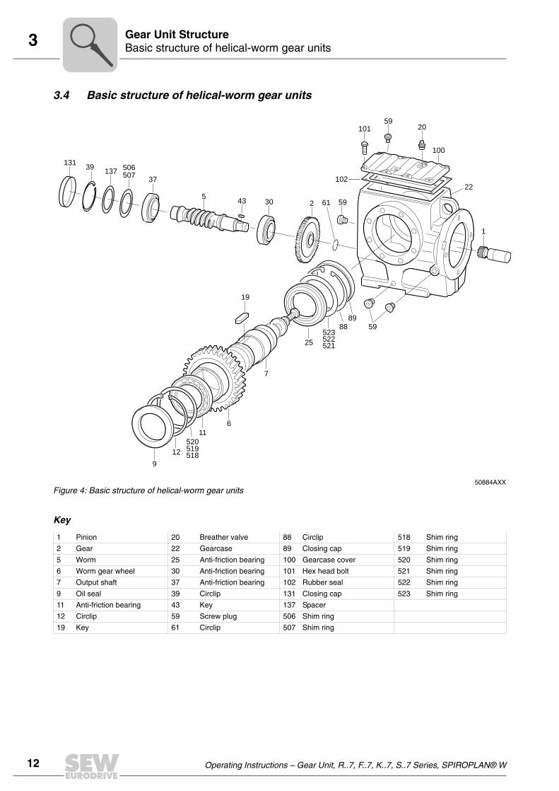
3.4 Basic structure of helical-worm gear units
Key
50884AXXFigure 4: Basic structure of helical-worm gear units
13139
137507506
37
543 30
9
12
520519518
11
6
7
25
88
89
59523522521
19
2 59
102
10159
20
22
1
100
61
1 Pinion 20 Breather valve 88 Circlip 518 Shim ring
2 Gear 22 Gearcase 89 Closing cap 519 Shim ring
5 Worm 25 Anti-friction bearing 100 Gearcase cover 520 Shim ring
6 Worm gear wheel 30 Anti-friction bearing 101 Hex head bolt 521 Shim ring
7 Output shaft 37 Anti-friction bearing 102 Rubber seal 522 Shim ring
9 Oil seal 39 Circlip 131 Closing cap 523 Shim ring
11 Anti-friction bearing 43 Key 137 Spacer
12 Circlip 59 Screw plug 506 Shim ring
19 Key 61 Circlip 507 Shim ring

Operating Instructions – Gear Unit, R..7, F..7, K..7, S..7 Series, SPIROPLAN® W 13
3Basic structure of SPIROPLAN® gear unitsGear Unit Structure
3.5 Basic structure of SPIROPLAN® gear units
Key
05674AXXFigure 5: Basic structure of SPIROPLAN® gear units
1
6872
1436671
65
100
102
22
89
521522523
88
25
6
250
251
17
7
11
8
19
518519520
12
9
101
1 Pinion 19 Key 88 Circlip 251 Circlip
6 Gear 22 Gearcase 89 Closing cap 518 Shim ring
7 Output shaft 25 Anti-friction bearing 100 Gearcase cover 519 Shim ring
8 Key 65 Oil seal 101 Hex head bolt 520 Shim ring
9 Oil seal 66 Anti-friction bearing 102 Gasket 521 Shim ring
11 Anti-friction bearing 71 Spacer 132 Circlip 522 Shim ring
12 Circlip 72 Circlip 183 Oil seal 523 Shim ring
17 Spacer 143 Spacer 250 Circlip

14 Operating Instructions – Gear Unit, R..7, F..7, K..7, S..7 Series, SPIROPLAN® W
3 Nameplate, unit designationGear Unit Structure
3.6 Nameplate, unit designation
Sample nameplate
Unit designation
Example: Helical gear unit, category II2GD
Example: Serial number
06687ADEFigure 6: Sample nameplate
fb = Service factorFRa max [N] = Maximum overhung load on the output sideFRe max [N] = Maximum overhung load on the input side (with input shaft assembly AD)i = Gear unit reduction ratioIM = Mounting positionIP.. = Enclosurene max [1/min] = Maximum input speedna [1/min] = Output speedMe max [Nm] = Maximum input torqueMa [Nm] = Output torqueMR [Nm] = Overload torque when using an AR adapterMRS [Nm] = Locking torque of the backstop
RF 47 / A / II2GD
Explosion-proof design to directive 94/9/EC
For direct motor mounting
Gear unit size
Helical gear unit series (flange mounted)
3229561201. 0001. 03
Year number end digits of the year of manufacture (2-digit)
Part number (4-digit)
Order number (10 digits)

Operating Instructions – Gear Unit, R..7, F..7, K..7, S..7 Series, SPIROPLAN® W 15
4Required tools / aidsMechanical Installation
4 Mechanical Installation4.1 Required tools / aids
• Set of spanners
• Torque wrench for:
– Shrink discs– AQH motor adapter– Input shaft assembly with centering shoulder
• Mounting device
• Shims and distance rings if necessary
• Fixing devices for input and output elements
• Lubricant (e.g. NOCO® Fluid)
• Bolt adhesive (for input shaft assembly with centering shoulder), e.g. Loctite® 243
• Standard parts are not part of the delivery
Installation tolerances
4.2 Prerequisites for assembly
Check that the following conditions have been met:
• The data on the nameplate of the gearmotor matches the voltage supply system.
• The drive has not been damaged during transportation or storage.
• Ensure that the following requirements have been met:
– For standard gear units:Ambient temperature according to the lubricant table in Sec. "Lubricants" (seestandard). The drive must not be assembled in the following ambient conditions:– Potentially explosive atmosphere– Oil– Acids– Gas– Vapors– Radiation
– For special versions:The drive configured in accordance with the ambient conditions.
– For helical-worm / SPIROPLAN® W gear units:No large external mass moments of inertia which could exert a retrodriving loadon the gear unit.[At η’ (retrodriving) = 2 – 1/η < 0.5 self-locking]
Shaft end Flanges
Diameter tolerance in accordance with DIN 748• ISO k6 for solid shafts with ∅ ≤ 50 mm• ISO m6 for solid shafts with ∅ > 50 mm• ISO H7 for hollow shafts• Center bore in accordance with DIN 332, shape
DR
Centering shoulder tolerance in accordance with DIN 42948• ISO j6 with b1 ≤ 230 mm• ISO h6 with b1> 230 mm

16 Operating Instructions – Gear Unit, R..7, F..7, K..7, S..7 Series, SPIROPLAN® W
4 Installing the gear unitMechanical Installation
• You must clean the output shafts and flange surfaces thoroughly to ensure they arefree of anti-corrosion agents, contamination or similar. Use a commercially availablesolvent. Do not let the solvent come into contact with the sealing lips of the oil seals– danger of damage to the material!
• When the drive is installed in abrasive ambient conditions, protect the output end oilseals against wear.
4.3 Installing the gear unit
The gear unit or gearmotor is only allowed to be installed in the specified mountingposition. SPIROPLAN® gear units are not dependent on the mounting position.
The support structure must have the following characteristics:
• Level
• Vibration damping
• Torsionally rigid
Maximum permitted flatness error for foot and flange mounting (approximate values withreference to DIN ISO 1101):
• Gear unit size ≤ 67: max. 0.4 mm
• Gear unit size 77 ... 107: max. 0.5 mm
• Gear unit size 137 ... 147: max. 0.7 mm
• Gear unit size 157 ... 187: max. 0.8 mm
Do not tighten the housing legs and mounting flanges against one another and ensurethat you comply with the permitted overhung and axial loads!
Secure the gearmotors with bolts of quality 8.8.
Secure the following gearmotors with bolts of quality 10.9:
• RF37, R37F with flange ∅ 120 mm
• RF47, R47F with flange ∅ 140 mm
• RF57, R57F with flange ∅ 160 mm
At the same time, also check that the oil fill is as specified for the mounting position (seeSec. "Lubricants" / "Lubricant fill quantities" or refer to the information on the nameplate).The gear units are filled with the required oil volume at the factory. There may be slightdeviations at the oil level plug as a result of the mounting position, which are permittedwithin the manufacturing tolerances.
The oil checking and drain screws and the breather valves must be freelyaccessible!

Operating Instructions – Gear Unit, R..7, F..7, K..7, S..7 Series, SPIROPLAN® W 17
4Installing the gear unitMechanical Installation
Adjust the lubricant fill volumes and the position of the breather valve accordinglyin the event of a change of mounting position.
Please contact our SEW customer service if you change the mounting position of K gearunits to M5 or M6 or between M5 and M6.
Please contact our SEW customer service if you change the mounting position of sizeS47 S97 S gear units to mounting position M2.
Use plastic inserts (2 ... 3 mm thick) if there is a risk of electrochemical corrosionbetween the gear unit and the driven machine. The material used must have an electri-cal bleeder resistor < 109 Ω. Electrochemical corrosion can occur between variousmetals, for example, cast iron and high-grade steel. Also install the bolts with plasticwashers! Ground the housing additionally – use the grounding bolts on the motor.
Installation in damp locations or in the open
Drives are supplied in corrosion-resistant versions for use in damp areas or in the openair. Repair any damage to the paint work (e.g. on the breather valve).
When mounting the motors onto AM, AQ, AR, AT adapters, seal the flange areas with asuitable sealing compound, e.g. Loctite® 574.

18 Operating Instructions – Gear Unit, R..7, F..7, K..7, S..7 Series, SPIROPLAN® W
4 Installing the gear unitMechanical Installation
Gear unit venting No breather plug is required for the following gear units:
• R07 in mounting positions M1, M2, M3, M5 and M6
• R17, R27 and F27 in mounting positions M1, M3, M5 and M6
• SPIROPLAN® W gear units
SEW-EURODRIVE supplies all other gear units with the breather valve installed andactivated according to the particular mounting position.
Exceptions:
1. SEW supplies the following gear units with a screw plug on the vent hole provided:
• Gear units for extended storage• Pivoted mounting positions, if possible• Gear units for mounting on a slant
The breather valve is located in the motor terminal box. Before startup, you must re-place the highest screw plug with the breather valve supplied.
2. SEW supplies a breather valve in a plastic bag for gear head units requiring ventingon the input end.
3. Enclosed gear units are supplied without a breather valve.
Activating the breather valve
As a rule, the breather valve is already activated at the factory. If the breather valve hasnot been activated, you must remove the transport fixture from the breather valve beforestarting up the gear unit!
Painting the gear unit
If you paint or respray the drive, ensure that you cover the breather valve and oil sealscarefully. Remove the strips of tape after completing the painting work.
1. Breather valve with transport fixture
2. Remove the transport fixture 3. Breather valve activated
02053BXX 02054BXX 02055BXX

Operating Instructions – Gear Unit, R..7, F..7, K..7, S..7 Series, SPIROPLAN® W 19
4Gear unit with solid shaftMechanical Installation
4.4 Gear unit with solid shaft
Installing input and output elements
The following figure shows a mounting device for installing couplings or hubs on gearunit or motor shaft ends. It may be possible to dispense with the thrust bearing on themounting device.
Avoid impermissibly high overhung loads: Install the gear or chain sprocket accordingto figure B.
• Only use a mounting device for installing input and output elements. Use the centerbore and the thread on the shaft end for positioning.
• Power transmission elements should be balanced after fitting and must not give riseto any impermissible radial or axial forces (see the "Gearmotor" or "Explosion-ProofDrives" catalogs for permitted values).
03371BXX
1) Gear shaft end2) Thrust bearing3) Coupling hub
03369BXX
1 = Hub
A = UnfavorableB = Correct
• Never drive belt pulleys, couplings, pinions, etc. onto the shaft end by hittingthem with a hammer This will damage the bearings, housing and the shaft!
• In the case of belt pulleys, make sure the belt is tensioned correctly in accor-dance with the manufacturer's instructions.
Note:
Assembly is easier if you first apply lubricant to the output element or heat it up briefly(to 80 ... 100 °C).

20 Operating Instructions – Gear Unit, R..7, F..7, K..7, S..7 Series, SPIROPLAN® W
4 Gear unit with solid shaftMechanical Installation
Installing couplings
Couplings must be mounted and balanced according to the information provided by thecoupling manufacturer:
a) Maximum and minimum clearance
b) Axial misalignment
c) Angular misalignment
03356AXXFigure 7: Clearance and misalignment for coupling installation
a) b) c)
Input and output elements such as belt pulleys, couplings, etc. must be protectedagainst contact!

Operating Instructions – Gear Unit, R..7, F..7, K..7, S..7 Series, SPIROPLAN® W 21
4Torque arms for mounted gear unitsMechanical Installation
4.5 Torque arms for mounted gear units
Do not place torque arms under strain during installation!
Parallel shaft helical gear units
Helical-bevel gear units
• Bush with bearings on both ends → (1).
• Install connection end B as a mirror image of A.
01029BXXFigure 8: Torque arm for parallel shaft helical
gear units
01030CXXFigure 9: Torque arm for helical-bevel gear units
Gear unit Bolts Tightening torque
KA37 4 × M10 × 25 – 8.8 48 Nm
KA47 4 × M10 × 30 – 8.8 48 Nm
KA67 4 × M12 × 35 – 8.8 86 Nm
KA77 4 × M16 × 40 – 8.8 210 Nm
KA87 4 × M16 × 45 – 8.8 210 Nm
KA97 4 × M20 × 50 – 8.8 410 Nm
KA107 4 × M24 × 60 – 8.8 710 Nm
KA127 4 × M36 × 130 – 8.8 2500 Nm
KA157 4 × M36 × 130 – 8.8 2500 Nm

22 Operating Instructions – Gear Unit, R..7, F..7, K..7, S..7 Series, SPIROPLAN® W
4 Torque arms for mounted gear unitsMechanical Installation
Helical-worm gear units
• Bush with bearings on both ends → (1).
SPIROPLAN® W gear units
• Bush with bearings on both ends → (1)
01031CXXFigure 10: Torque arm for helical-worm gear units
Gear unit Bolts Tightening torque
SA37 M6 × 16 – 8.8 11 Nm
SA47 M8 × 20 – 8.8 25 Nm
SA57 M8 × 20 – 8.8 25 Nm
SA67 M12 × 25 – 8.8 86 Nm
SA77 M12 × 35 – 8.8 86 Nm
SA87 M16 × 35 – 8.8 210 Nm
SA97 M16 × 35 – 8.8 210 Nm
02050CXXFigure 11: Torque arm for SPIROPLAN® W gear units
Gear unit Bolts Tightening torque
WA10 M6 × 16 11 Nm
WA20 M6 × 16 11 Nm
WA30 M6 × 16 11 Nm
45°
(1)

Operating Instructions – Gear Unit, R..7, F..7, K..7, S..7 Series, SPIROPLAN® W 23
4Mounted gear unit with keyway or splined hollow shaftMechanical Installation
4.6 Mounted gear unit with keyway or splined hollow shaft
Installation notes 1. Apply NOCO® fluid.
2. Distribute the NOCO® fluid carefully.
3. Install the shaft and secure it axially
(mounting is facilitated by using a mounting device)
3A: Mounting with standard scope of delivery
For the configuration of customer shafts, please also refer to the design notes in theGearmotors catalog!
02042BXX
02043AXX
03361BXX
1 Short retaining bolt(standard scope of delivery)
2 Lock washer3 Washer4 Circlip6 Customer shaft
NO
CO
FLUI
®
NO
CO
FLUI
®
A
12
34
6

24 Operating Instructions – Gear Unit, R..7, F..7, K..7, S..7 Series, SPIROPLAN® W
4 Mounted gear unit with keyway or splined hollow shaftMechanical Installation
3B: Assembly with SEW-EURODRIVE assembly/disassembly kit (→ page 26)
– Customer's shaft with contact shoulder
3C: Assembly with SEW-EURODRIVE assembly/disassembly kit (→ page 26)
– Customer's shaft without contact shoulder
4. Tighten the retaining bolt to the appropriate torque (see table).
03362BXX
1 Retaining bolt2 Lock washer3 Washer4 Circlip6 Customer's shaft with contact
shoulder
03363AXX
1 Retaining bolt2 Lock washer3 Washer4 Circlip5 Spacer6 Customer's shaft without
contact shoulder
03364AXX
Bolt Tightening torque [Nm]
M5 5
M6 8
M10/12 20
M16 40
M20 80
M24 200
B
12 3
4
6
C
12 3
45
6
Note:
To avoid contact corrosion, we recommend that the customer's shaft should additionallybe recessed between the two contact surfaces!

Operating Instructions – Gear Unit, R..7, F..7, K..7, S..7 Series, SPIROPLAN® W 25
4Mounted gear unit with keyway or splined hollow shaftMechanical Installation
Removal notes This description is only applicable when the gear unit was assembled using the installa-tion/removal kit from SEW-EURODRIVE(→ page 26) (see the previous description,point 3B or 3C).
1. Loosen the retaining bolt [1].
2. Remove parts 2 to 4 and, if fitted, spacer 5.
3. Insert the forcing washer [8] and the fixed nut [7] from the SEW-EURODRIVE instal-lation/removal kit between the customer's shaft [6] and the circlip [4].
4. Re-insert the circlip [4].
5. Screw the retaining bolt [1] back in. Now you can force the gear unit off the shaft bytightening the bolt.
03366AXX
1 Retaining bolt2 Lock washer3 Washer4 Circlip5 Spacer6 Customer shaft
03367AXX
1 Retaining bolt4 Circlip6 Customer shaft7 Fixed nut8 Forcing washer
12 3
45
6
1
47
8
6

26 Operating Instructions – Gear Unit, R..7, F..7, K..7, S..7 Series, SPIROPLAN® W
4 Mounted gear unit with keyway or splined hollow shaftMechanical Installation
SEW installation/removal kit
The SEW-EURODRIVE installation/removal kit can be ordered under the following partnumber.
03394AXXFigure 12: SEW-EURODRIVE installation/removal kit
1 Retaining bolt7 Fixed nut for disassembly8 Forcing washer
1
8 7
7
1
Type DH7 [mm]
M1) C4 [mm]
C5 [mm]
C6 [mm]
U-0.5 [mm]
T -0.5 [mm]
D3-0.5 [mm]
L4 [mm]
Part number of installa-
tion/removal kit
WA..10 16 M5 5 5 12 4.5 18 15.7 50 643 712 5
WA..20 18 M6 5 6 13.5 5.5 20.5 17.7 25 643,682 X
WA..20, WA..30, SA..37 20 M6 5 6 15.5 5.5 22.5 19.7 25 643 683 8
FA..27, SA..47 25 M10 5 10 20 7.5 28 24.7 35 643 684 6
FA..37, KA..37, SA..47, SA..57 30 M10 5 10 25 7.5 33 29.7 35 643 685 4
FA..47, KA..47, SA..57 35 M12 5 12 29 9.5 38 34.7 45 643 686 2
FA..57, KA..57, FA..67, KA..67, SA..67 40 M16 5 12 34 11.5 41.9 39.7 50 643 687 0
SA..67 45 M16 5 12 38.5 13.5 48.5 44.7 50 643 688 9
FA..77, KA..77, SA..77 50 M16 5 12 43.5 13.5 53.5 49.7 50 643 689 7
FA..87, KA..87, SA..77, SA..87 60 M20 5 16 56 17.5 64 59.7 60 643 690 0
FA..97, KA..97, SA..87, SA..97 70 M20 5 16 65.5 19.5 74.5 69.7 60 643 691 9
FA..107, KA..107, SA..97 90 M24 5 20 80 24.5 95 89.7 70 643 692 7
FA..127, KA..127 100 M24 5 20 89 27.5 106 99.7 70 643 693 5
FA..157, KA..157 120 M24 5 20 107 31 127 119.7 70 643 694 3
1) Retaining bolt
The SEW assembly kit for mounting the customer shaft is a recommendation from SEW-EURODRIVE. You must always check whether this design can compensate the axial loads. In particular applications (e.g. mounting mixer shafts), a different design may have to be used to secure the shaft axially. In these cases, customers can use their own devices. However, you must ensure that these designs do not cause potential sources of combustion according to DIN EN 13463 (for example, impact sparks).

Operating Instructions – Gear Unit, R..7, F..7, K..7, S..7 Series, SPIROPLAN® W 27
4Mounted gear units with shrink discMechanical Installation
4.7 Mounted gear units with shrink disc
Installation notes • Do not tighten the locking bolts unless the shaft is installed - the hollow shaft couldbecome deformed!
1. Loosen the locking bolts by a few turns (do not unscrew them completely!).
2. Carefully degrease the hollow shaft hole and the input shaft.
51092AXX 51093AXX
3. Hollow shaft/input shaft after degreasing 4. Apply NOCO® fluid to the input shaft1) in the area of the bushing.
51094AXX 51095AXX
1) It is essential to make sure that the clamping area of the shrink disk is free from grease! For this reason, never apply NOCO® fluid directly to the bushing as the paste may be able to get into the clamping area of the shrink disk when the input shaft is put on.
A B

28 Operating Instructions – Gear Unit, R..7, F..7, K..7, S..7 Series, SPIROPLAN® W
4 Mounted gear units with shrink discMechanical Installation
5. Install the input shaft, making sure that the locking collars of the shrink disk are in-stalled in parallel to each other2). For gear unit housing with a shaft collar, mountthe shrink disc to the stop on the shaft collar. For gear unit housing without ashaft collar, mount the shrink disk with a clearance of 1 to 2 mm from the gearunit housing. Tighten the locking bolts with the torque wrench by working roundseveral times from one bolt to the next (not in diametrically opposite sequence) untilthe bolts cannot be tightened any more. See the following table for tighteningtorques.
51096AXX
s>1mm1-2mm
2)After installation
• There must be a gap s > 1 mm between the locking collars
• Grease the outside of the hollow shaft in the area of the shrink disk to prevent corro-sion.
Gear unit type Bolt Nm max.1)
SH37 M5 5
60°
KH37...77 FH37...77 SH47...77 M6 12
KH87/97 FH87/97 SH87/97 M8 30
KH107 FH107 M10 59
KH127/157 FH127 M12 100
KH167 M16 250
KH187 M20 470
1) Maximum tightening angle per cycle

Operating Instructions – Gear Unit, R..7, F..7, K..7, S..7 Series, SPIROPLAN® W 29
4Mounted gear units with shrink discMechanical Installation
Notes on removing the shrink disk
1. Unscrew the locking bolts evenly one after the other. Each locking bolt may only beunscrewed by about one quarter turn in the initial cycle. This is in order to avoid tiltingand jamming the locking collars. Do not fully unscrew the locking bolts!
2. Remove the shaft or pull the hub off the shaft. (You must first remove any rust thatmay have formed between the hub and the end of the shaft.)
3. Pull the shrink disk off the hub.
Cleaning and lubricating the shrink disk
There is no need to strip down and re-grease disassembled shrink disks before they arescrewed back on.
The shrink disk only needs to be cleaned and re-greased if it is contaminated.
Use one of the following solid lubricants for the tapered surfaces.
Grease the locking bolts with a multipurpose grease such as Molykote BR 2 or similar.
Caution!
Risk of injury if the shrink disk is not removed correctly!
Lubricant (Mo S2) Sold as
Molykote 321 (lube coat)Molykote spray (powder spray)Molykote G RapidAemasol MO 19PAemasol DIO-sétral 57 N (lube coat)
SpraySpraySpray or pasteSpray or pasteSpray

30 Operating Instructions – Gear Unit, R..7, F..7, K..7, S..7 Series, SPIROPLAN® W
4 Mounted gear units with TorqLOC®Mechanical Installation
4.8 Mounted gear units with TorqLOC®
1. Clean the inside of the hollow shaft and the customer shaft. Ensure that all traces ofgrease or oil are removed.
2. Install the split ring and the bushing on the customer shaft.
3. Apply NOCO® fluid to the bushing and distribute it carefully.
4. Push the gear unit onto the customer shaft.
52089AXX
52090AXX
52091AXX
NO
CO
FLUID
®

Operating Instructions – Gear Unit, R..7, F..7, K..7, S..7 Series, SPIROPLAN® W 31
4Mounted gear units with TorqLOC®Mechanical Installation
5. Preassemble the torque arm (do not tighten the bolts).
6. Push the busing onto the gear unit up to the stop.
7. Tighten all the retaining bolts for the torque arm.
52092AXX
52093AXX
52094AXX
K...
S...F...

32 Operating Instructions – Gear Unit, R..7, F..7, K..7, S..7 Series, SPIROPLAN® W
4 Mounted gear units with TorqLOC®Mechanical Installation
8. Secure the bushing with the split ring. Tighten the split ring on the bushing using theappropriate torque as specified in the following table.
9. Slide the shrink disk onto the hollow shaft. Ensure that all bolts have been loosened.
52095AXX
Type Torque [Nm]
KT/FT ST Nickel plated Stainless steel
- 37 18 7.5
37 47 18 7.5
47 57 18 7.5
57, 67 67 35 18
77 77 35 18
87 87 35 18
97 97 35 18
52096AXX

Operating Instructions – Gear Unit, R..7, F..7, K..7, S..7 Series, SPIROPLAN® W 33
4Mounted gear units with TorqLOC®Mechanical Installation
10.Push the counter bushing onto the customer shaft and into the hollow shaft or shrinkdisk right into the seat.
11.Tap lightly on the flange of the counter bushing to ensure that the socket is fitted se-curely in the hollow shaft.
12.Ensure that the customer shaft is fitted in the counter bushing.
52097AXX
52098AXX
53478AXX

34 Operating Instructions – Gear Unit, R..7, F..7, K..7, S..7 Series, SPIROPLAN® W
4 Mounted gear units with TorqLOC®Mechanical Installation
13.Tighten the bolts of the shrink disk by hand and ensure that the end rings of the shrinkdisc are parallel.
14.Tighten the locking bolts by working round several times from one bolt to the next(not in diametrically opposite sequence). See the table for tightening torques.
52100AXX
After installation, the remaining gap between the outer rings of the shrinkdiscs must be > 0 mm.
52101AXX
Type Nickel plated Stainless steel
KT/FT ST Torque [Nm]
- 37 4.1 6.8
37 47 10 6.8
47 57 12 6.8
57, 67 67 12 15
77 77 30 30
87 87 30 50
97 97 30 50
> 0mm

Operating Instructions – Gear Unit, R..7, F..7, K..7, S..7 Series, SPIROPLAN® W 35
4Mounted gear units with TorqLOC®Mechanical Installation
15.The distance between the counter bushing and the hollow shaft end and between thesplit ring and the clamping ring must not exceed the following values. The followingtable lists the maximum and minimum gap width.
52102AXX
Type Distance [mm]
KT/FT ST a min. a max.
- 37 3.3 5.6
37 47 3.3 5.6
47 57 5.0 7.6
57, 67 67 5.0 7.6
77 77 5.0 7.6
87 87 5.8 8.6
97 97 5.8 8.6
a
a

36 Operating Instructions – Gear Unit, R..7, F..7, K..7, S..7 Series, SPIROPLAN® W
4 AM adapter couplingMechanical Installation
4.9 AM adapter coupling
IEC adapter AM63 225 / NEMA adapter AM56 365
1. Clean the motor shaft and flange surfaces of the motor and adapter.
2. Remove the key from the motor shaft and replace it with the supplied key (484) (notAM63 and AM250).
3. Heat the coupling half (479) to approx. 80 – 100 °C, push the coupling half onto themotor shaft.
Until stop at motor shaft shoulder (position to point A except for AM25 / AM280 andNEMA).
4. Secure key and coupling half using grub screw (481) and tightening torque TA on mo-tor shaft according to the table.
5. Check point A.
6. Seal the contact surfaces between the adapter and motor using a suitable sealingcompound.
7. Mount the motor on the adapter. When doing this, make sure the coupling dogs ofthe adapter shaft engage in the plastic spider.
04469CXX
1 = Motor shaft
IEC AM 63 / 71 80 / 90 100 / 112 132 160 / 180 200 225 250 / 280
A 24.5 31.5 41.5 54 76 78.5 93.5 139
TA 1.5 1.5 4.8 4.8 10 17 17 17
Thread M4 M4 M6 M6 M8 M10 M10 M10
NEMA AM 56 143 / 145 182 / 184 213 / 215 254 / 256 284 / 286 324 / 326 364 / 365
A 46 43 55 63.5 78.5 85.5 107 107
TA 1.5 1.5 4.8 4.8 10 17 17 17
Thread M4 M4 M6 M6 M8 M10 M10 M10

Operating Instructions – Gear Unit, R..7, F..7, K..7, S..7 Series, SPIROPLAN® W 37
4AM adapter couplingMechanical Installation
Permitted loads
To avoid contact corrosion, we recommend applying NOCO® fluid to the motor shaftbefore mounting the coupling half.
When installing a motor onto the adapter, you must use an anaerobic fluid seal toensure that moisture cannot penetrate the adapter.
The load data specified in the following table must not be exceeded when a motoris mounted.
51102AXX
Adapter type Fq1) [N]
IEC NEMA x1) [mm]
1) The maximum permitted weight of the attached motor Fqmax must be reduced proportionally as the dis-tance between the adapter flange and the middle of the motor (x) increases. When this distance is redu-ced, the maximum permitted weight Fqmax cannot be increased.
IEC adapter NEMA adapter
AM63/71 AM56 77 530 410
AM80/90 AM143/145 113 420 380
AM100/112 AM182/184 144 2000 1760
AM132 2)
2) Diameter of the adapter drive flange: 160 mm
AM213/2152)
1861600 1250
AM132.. AM213/215 4700 3690
AM160/180 AM254/286 251 4600 4340
AM200/225 AM324 - AM365 297 5600 5250
AM250/280 - 390 11200 -
X
Fq

38 Operating Instructions – Gear Unit, R..7, F..7, K..7, S..7 Series, SPIROPLAN® W
4 AQ adapter couplingMechanical Installation
Adapter AM with backstop AM../RS
Check the direction of rotation of the drive before installation and startup. Please informthe SEW-EURODRIVE customer service if the direction of rotation is incorrect.
The backstop is maintenance-free in operation, and does not require any further main-tenance work.
The backstops have a minimum lift-off speed depending on the size (→ following table).If the minimum lift-off speeds are violated, the backstops are subject to wear, and theresulting friction causes the temperature to increase.
4.10 AQ adapter coupling
1. Clean the motor shaft and flange surfaces of the motor and adapter.
2. Type AQH: Unscrew the bolts of the coupling half (479) and loosen the conicalconnection.
3. Heat the coupling half (80 °C – 100 °C) and push it onto the motor shaft.
Type AQA / AQH: Up to clearance "A" (see table).
4. Type AQH: Tighten the bolts on the coupling half in diametrically opposite sequence
TypeMaximum locking torque of backstop
[Nm]Minimum lift-off speed
[1/min]
AM80/90/RS,AM143/145/RS 90 640
AM100/112/RS,AM182/184/RS 340 600
AM132/RS,AM213/215/RS 700 550
AM160/180/RS,AM254/286/RS 1200 630
AM200/225/RS, AM324-365/RS 1450 430
In rated operation, the lift-off speeds must not drop below the minimum values.The lift-off speeds are only permitted to drop below the minimum values duringstart-up or braking.
53512AXX
1 Motor shaft2 Setscrew3 Bolt
AQA = With keywayAQH = Without keyway
479
A
479
A
1
1
2 3
AQA AQH

Operating Instructions – Gear Unit, R..7, F..7, K..7, S..7 Series, SPIROPLAN® W 39
4AQ adapter couplingMechanical Installation
(work round several times tightening the bolts evenly one after the other) until allbolts reach the tightening torque TA specified in the table.
Type AQA: Use a setscrew to secure the coupling half (see table).
5. Check the position of the coupling half (clearance "A", see table).
Install motor onto the adapter making sure that the dogs of the two coupling halvesengage in each other. The force that must be applied when joining the two couplinghalves is dissipated after final assembly, so there is no risk of any axial load beingapplied to adjacent bearings.
Setting dimen-sions, tightening torques
Only for AQA, not permitted for AQH: To avoid contact corrosion, we recommendapplying NOCO® fluid to the motor shaft before mounting the coupling half.
When installing a motor onto the adapter, you must use an anaerobic fluid seal toensure that moisture cannot penetrate the adapter.
Type Coupling size Clearance "A" [mm]
Bolts DIN 912 Tightening torque TA [Nm]
AQA AQH AQA AQH
AQA /AQH 80 /1/2/3
19/24
44,5
M5 M4 2 3AQA /AQH 100 /1/2 39
AQA /AQH 100 /3/4 53
AQA /AQH 115 /1/2 62
AQA /AQH 115 /324/28
62M5 M5 2 6
AQA /AQH 140 /1/2 62
AQA /AQH 140 /328/38
74,5M8 M5 10 6
AQA /AQH 190 /1/2 76,5
AQA /AQH 190 /3 38/45 100 M8 M6 10 10

40 Operating Instructions – Gear Unit, R..7, F..7, K..7, S..7 Series, SPIROPLAN® W
4 AD input shaft assemblyMechanical Installation
4.11 AD input shaft assembly
Please refer to Sec. "Installing input and output shafts" for information on mounting ofinput elements.
Cover with motor mounting plat-form AD../P
Mounting the motor and adjusting the motor mounting platform.
1. Set the motor mounting platform to the required mounting position by evenly tighten-ing the adjusting nuts. It may be necessary to remove the lifting eyebolt from helicalgear units in order to achieve the lowest adjustment position. Touch up any damageto the paint work.
2. Align the motor on the motor mounting platform (shaft ends must be in alignment)and secure it.
3. Mount the input elements on the input shaft end and the motor shaft. Line them upwith one another. Correct the motor position again if necessary.
4. Put on traction elements (V-belt, chain, etc.) and apply a preload by evenly adjustingthe motor mounting platform. Do not stress the motor mounting platform and thecolumns against one another when doing this.
5. Tighten the threaded columns using the nuts which are not used for adjustment.
Only AD6/P and AD7/P:
Unscrew the nuts on the stud bolts before adjustment to allow the stud bolts to moveaxially in the support without restriction. Do not tighten the nuts until the final adjustmentposition has been achieved. Do not adjust the motor mounting platform using thesupport.
03519BXX
1 Motor mounting platform2 Stud bolt (only AD6/P / AD7/P)3 Support (only AD6/P / AD7/P)4 Nut5 Threaded column

Operating Instructions – Gear Unit, R..7, F..7, K..7, S..7 Series, SPIROPLAN® W 41
4AD input shaft assemblyMechanical Installation
Type with center-ing shoulder AD../ZR
Mounting applications on the input shaft assembly with centering shoulder.
1. Retaining bolts of a suitable length must be used to secure the application. Thelength l of the new bolts is calculated as follows:
Round down the calculated bolt length to the next smaller standard length.
2. Remove the retaining bolts from the centering shoulder.
3. Clean the contact surface and the centering shoulder.
4. Clean the threads of the new bolts and apply a bolt locking compound (e.g. Loctite243) to the first few threads.
5. Position the application against the centering shoulder and tighten the retaining boltsto the specified tightening torque TA (see table).
02725CXX
l = t + at = Screw-in depth (see table)a = Thickness of the applications = Retaining thread (see table)
TypeScrew-in depth
t [mm]Retaining thread
s
Tightening torqueTA for connection bolts in strength class 8.8
[Nm]
AD2/ZR 25,5 M8 25
AD3/ZR 31,5 M10 48
AD4/ZR 36 M12 86
AD5/ZR 44 M12 86
AD6/ZR 48,5 M16 210
AD7/ZR 49 M20 410
AD8/ZR 42 M12 86

42 Operating Instructions – Gear Unit, R..7, F..7, K..7, S..7 Series, SPIROPLAN® W
4 AD input shaft assemblyMechanical Installation
Permitted loads
The load values specified in the following table must not be exceeded.
53513AXX
x
Fq
Typex1)
[mm]
1) Maximum load values for connection bolts in strength class 8.8. The maximum permitted weight of theattached motor Fqmax must be reduced proportionally as the distance between the adapter flange and themiddle of the motor (x) increases When this distance is reduced, the Fqmax cannot be increased.
Fq1)
[N]
AD2/ZR 193 330
AD3/ZR 274 1400
AD4/ZR2)
2) Diameter of the adapter output flange: 160 mm
3611120
AD4/ZR 3300
AD5/ZR 487 3200
AD6/ZR 567 3900
AD7/ZR 663 10000
AD8/ZR 516 4300

Operating Instructions – Gear Unit, R..7, F..7, K..7, S..7 Series, SPIROPLAN® W 43
4AD input shaft assemblyMechanical Installation
Cover with back-stop AD../RS
Check the direction of rotation of the drive before installation and startup. Please informthe SEW-EURODRIVE customer service if the direction of rotation is incorrect.
The backstop is maintenance-free in operation, and does not require any further main-tenance work.
The backstops have a minimum lift-off speed depending on the size (→ following table).If the minimum lift-off speeds are violated, the backstops are subject to wear, and theresulting friction causes the temperature to increase.
TypeMaximum locking torque of backstop
[Nm]Minimum lift-off speed
[1/min]
AD2/RS 90 640
AD3/RS 340 600
AD4/RS 700 550
AD5/RS 1200 630
AD6/RS 1450 430
AD7/RS 1450 430
AD8/RS 2860 430
In rated operation, the lift-off speeds must not drop below the minimum values.The lift-off speeds are only permitted to drop below the minimum values duringstart-up or braking.
44 Operating Instructions – Gear Unit, R..7, F..7, K..7, S..7 Series, SPIROPLAN® W
5 Startup of helical-worm and SPIROPLAN® W gear unitsStartup
5 Startup
5.1 Startup of helical-worm and SPIROPLAN® W gear units
Run-in period SPIROPLAN® and helical-worm gear units require a run-in period of at least 24 hoursbefore reaching their maximum efficiency. A separate run-in period applies for eachdirection of rotation if the gear unit is operated in both directions of rotation. The tableshows the average power reduction during the run-in period.
5.2 Startup of helical, parallel shaft helical and helical-bevel gear units
No special startup instructions are required for helical, parallel shaft helical and helical-bevel gear units providing the gear units have been installed in accordance with Sec."Mechanical Installation".
Prior to startup check that the oil level is as specified for the mounting position.The oil checking and drain screws and the breather valves must be freely acces-sible.
Note: The direction of rotation of the output shaft in series S..7 helical-worm gear unitshas been changed from CW to CCW; this is different from the S..2 series. Changedirection of rotation: Swap over two motor feeder cables.
No. of starts
Worm Spiroplan®
Power reduction i range Power reduction i range
1 start ca. 12 % ca. 50...280 ca. 15 % approx. 40 ... 75
2 start ca. 6 % ca. 20...75 ca. 10 % ca. 20...30
3 start ca. 3 % ca. 20...90 ca. 8 % ca. 15
4 start - - ca. 8 % ca. 10
5 start ca. 3 % ca. 6...25 ca. 5 % ca. 8
6 start ca. 2 % ca. 7...25 - -
00
I

Operating Instructions – Gear Unit, R..7, F..7, K..7, S..7 Series, SPIROPLAN® W 45
6Inspection and maintenance intervalsInspection and Maintenance
6 Inspection and Maintenance6.1 Inspection and maintenance intervals
6.2 Lubricant change intervals
Frequency What to do?
• Every 3000 machine hours, at least every 6 months.
• Check oil and oil level.• Check the seals visually for leakage.• For gear units with a torque arm: Check the
rubber buffer and change it, if necessary
• Depending on the operating conditions (see chart below), every 3 years at the latest.
• According to oil temperature.
• Change mineral oil.
• Replace anti-friction bearing grease (recom-mendation).
• Replace oil seal (do not install it in the same track).
• Depending on the operating conditions (see chart below), every 5 years at the latest.
• According to oil temperature.
• Change synthetic oil
• Replace anti-friction bearing grease (recom-mendation).
• Replace oil seal (do not install it in the same track).
• Gear unitsR07, R17, R27, F27 and Spiroplan® are have lubrication for life and are therefore mainte-nance-free
• Varying (depending on external factors). • Touch up or renew the surface/anticorrosion coating.
53232AXXFigure 13: Oil change intervals for standard gear units under normal environmental conditions
[1] Operating hours
[2] Sustained oil bath temperature
• Average value per oil type at 70 °C
[3] CLP PG
[4] CLP HC / HCE
[5] CLP / HLP / E
5000
10000
15000
20000
25000
30000
[h]
120
[°C]
110 1151009080700
[1]
[2]
[3]
[4]
[5]
OilOil

46 Operating Instructions – Gear Unit, R..7, F..7, K..7, S..7 Series, SPIROPLAN® W
6 Inspection and maintenance of the gear unitInspection and Maintenance
6.3 Inspection and maintenance of the gear unit
Do not intermix synthetic lubricants and do not mix synthetic and mineral lubricantstogether!
The standard lubricant is mineral oil (except for Spiroplan® gear units).
The position of the oil level and oil drain plug and the breather valve depends onthe mounting position. Refer to the diagrams of the mounting positions.
Checking the oil level
1. De-energize the gearmotor and secure it to prevent it from being switched oninadvertently!
Wait until the gear unit has cooled off – Danger of burns!
2. Refer to Sec. "Installing the gear unit" when changing the mounting position!
3. For gear units with an oil level plug: Remove the oil level plug, check the fill level andcorrect it if necessary. Screw the oil level plug back in.
Checking the oil 1. De-energize the gearmotor and secure it to prevent it from being switched oninadvertently!
Wait until the gear unit has cooled off – Danger of burns!
2. Remove a little oil from the oil drain plug.
3. Check the oil consistency.
– Viscosity– If you can see that the oil is heavily contaminated, we recommend that you
change the oil even if this is outside the service intervals specified in "Inspectionand maintenance periods".
4. For gear units with an oil level plug: Remove the oil level plug, check the fill level andcorrect it if necessary. Screw the oil level plug back in.
Changing the oil Only change the oil when the gear unit is at operating temperature.
De-energize the gearmotor and secure it to prevent it from being switched backon inadvertently!
Wait until the gear unit cools down - Danger of burns!
Note: The gear unit must still be warm otherwise the high viscosity of excessivelycold oil will make it harder to drain the oil correctly.
With oil drain plug / oil level screw
1. Place a container underneath the oil drain plug
2. Remove the oil level plug, breather plug/breather valve and oil drain plug.
3. Drain all the oil.
4. Screw in the oil drain plug.
5. Pour in new oil of the same type through the vent hole (if changing the oil type, pleasefirst contact our customer service). Do not mix synthetic lubricants.
– Pour in the volume of oil in accordance with the mounting position (see Sec. "Lu-bricant fill quantities") or as specified on the nameplate.
– Check at the oil level plug.
6. Screw the oil level plug back in
7. Screw in the breather plug/breather valve.

Operating Instructions – Gear Unit, R..7, F..7, K..7, S..7 Series, SPIROPLAN® W 47
6Inspection / maintenance of AM / AQA adaptersInspection and Maintenance
Without oil drain plug / oil level plug
1. Remove cover plate.
2. Drain the oil through the cover plate opening.
3. Pour in new oil of the same type through the vent hole (if changing the oil type, pleasefirst contact our customer service). Do not mix synthetic lubricants.
– Pour in the volume of oil in accordance with the mounting position (see Sec. "Lu-bricant fill quantities") or as specified on the nameplate.
4. Check the oil level (→ Sec. "Check oil level for gear units with oil level plug")
5. Attach cover plate (observe the tightening torque and series → Sec. "Check the oillevel for gear units without an oil level plug")
Changing the oil seal
1. De-energize the gearmotor and secure it to prevent it from being switched oninadvertently!
Wait until the gear unit has cooled off – Danger of burns!
2. When changing the oil seal, ensure that there is a sufficient grease reservoir betweenthe dust lip and protective lip, depending on the type of gear unit.
3. If you use double oil seals, the space has to be filled one-third with grease.
6.4 Inspection / maintenance of AM / AQA adapters
6.5 Inspection / maintenance of AD adapters
Frequency What to do?
• Every 3000 machine hours, at least every 6 months • Check torsional play• Visually check the elastic annular gear• Check the adapter visually for leakage
• After 25000 - 30000 machine hours • Renew the anti-friction bearing grease• Replace oil seal (do not install it in the
same track)• Change the elastic annular gear.
Frequency What to do?
• Every 3000 machine hours, at least every 6 months • Check running noise for possible bearing damage
• Check the adapter visually for leakage
• After 25000 - 30000 machine hours • Renew the anti-friction bearing grease
• Change the oil seal

48 Operating Instructions – Gear Unit, R..7, F..7, K..7, S..7 Series, SPIROPLAN® W
7 Gear unit malfunctionsMalfunctions
7 MalfunctionsCustomer service
7.1 Gear unit malfunctions
7.2 AM / AQA / AL adapter malfunctions
Please have the following information to hand if you require the assistance of our customer service:• Data from the nameplate (complete)• Nature and extent of the fault• Time and peripheral circumstances of the fault• Presumed cause
Problem Possible cause Remedy
Unusual, regular running noise
A Meshing/grinding noise: Bearing damage.B Knocking noise: Irregularity in the gearing
A Check the oil (see Sec. "Inspection and Mainte-nance"), change bearings
B Contact customer service
Unusual, irregular running noise
Foreign bodies in the oil • Check the oil (see Sec. "Inspection and Mainte-nance")
• Stop the drive, contact customer service
Oil leaking1)
• From the gear cover plate
• From the motor flange• From the motor oil seal• From the gear unit
flange• From the output end oil
seal
1) Short-term oil/grease leakage at the oil seal is possible in the run-in phase (24 hours running time).
A Rubber seal on the gear cover plate leak-ing
B Seal defectiveC Gear unit not vented
A Tighten the bolts on the gear cover plate and observe the gear unit. Oil still leaking: Contact cus-tomer service
B Contact customer serviceC Vent the gear unit (see Sec. "Mounting Positions")
Oil leaking from breather valve
A Too much oilB Drive operated in incorrect mounting posi-
tionC Frequent cold starts (oil foams) and/or
high oil level
A Correct the oil level (see Sec. "Inspection and Maintenance")
B Mount the breather valve correctly (see Sec. "Mounting Positions") and correct the oil level (see "Lubricants")
Output shaft does not turn although the motor is run-ning or the input shaft is rotated
Connection between shaft and hub in gear unit interrupted
Send in the gear unit/gearmotor for repair
Problem Possible cause Remedy
Unusual, regular running noise
Meshing/grinding noise: Bearing damage Contact SEW-EURODRIVE customer service
Oil leaking Seal defective Contact SEW-EURODRIVE customer service
Output shaft does not turn although the motor is run-ning or the input shaft is rotated
Connection between shaft and hub in gear unit interrupted
Send the gear unit to SEW-EURODRIVE for repair.
Change in running noise and / or vibrations occur
A Annular gear wear, short-term torque transfer through metal contact
B Bolts to secure hub axially are loose.
A Change the annular gear B Tighten the bolts
Premature wear in annular gear
A Contact with aggressive fluids / oil; ozone influence; too high ambient temperatures etc, which can cause a change in the physical properties of the annular gear.
B Impermissibly high ambient/contact tem-perature for the annular gear; maximum permitted temperature –20 °C to +80 °C.
C Overload
Contact SEW-EURODRIVE customer service

Operating Instructions – Gear Unit, R..7, F..7, K..7, S..7 Series, SPIROPLAN® W 49
7AD input shaft assembly malfunctionsMalfunctions
7.3 AD input shaft assembly malfunctions
Problem Possible cause Remedy
Unusual, regular running noise
Meshing/grinding noise: Bearing damage. Contact SEW-EURODRIVE customer service
Oil leaking Seal defective Contact SEW-EURODRIVE customer service
Output shaft does not turn although the input shaft is rotated.
Connection between shaft and hub in gear unit or cover interrupted
Send the gear unit to SEW-EURODRIVE for repair.

50 Operating Instructions – Gear Unit, R..7, F..7, K..7, S..7 Series, SPIROPLAN® W
8 General information on mounting positionsMounting Positions
8 Mounting Positions8.1 General information on mounting positions
Mounting position designation
SEW differentiates between six mounting positions M1 ... M6 for gear units. The following figure shows the spatial orientation of the gearmotor in mounting positions M1 ... M6.
03203AXXFigure 14: Depiction of mounting positions M1 ... M6
M1
M1
M1
M1
M1
M1
M4
M4
M4
M4
M4
M4
M3
M3
M3
M3
M3
M3
M6
M6
M6
M6
M6
M6
M5
M5
M5
M5
M5
M5
M2
M2
M2
M2
M2
M2
R..
F..
K..W..S..
M1 … M6M1 … M6

Operating Instructions – Gear Unit, R..7, F..7, K..7, S..7 Series, SPIROPLAN® W 51
8Key to the mounting position sheetsMounting Positions
8.2 Key to the mounting position sheets
Important: SPIROPLAN® gearmotors cannot be equipped with breather valves, oillevel plugs or drain plugs.
Symbols used The following table shows the symbols used in the mounting position sheets and whatthey mean:
Churning losses Increased churning losses may arise in some mounting positions. ContactSEW-EURODRIVE in case of the following combinations:
SPIROPLAN® gearmotors do not depend on any particular mounting position. However,mounting positions M1 to M6 are also shown for SPIROPLAN® gearmotors to assist youin working with this documentation.
Symbol Meaning
Breather valve
Oil level plug
Oil drain plug
Mounting position Gear unit type Gear unit sizeInput speed
[1/min]
M2, M4 R97 ... 107 > 2500
> 107 >1500
M2, M3, M4, M5, M6
F97 ... 107 > 2500
> 107 > 1500
K77 ... 107 > 2500
> 107 > 1500
S 77 ... 97 > 2500
M1 … M6M1 … M6

52 Operating Instructions – Gear Unit, R..7, F..7, K..7, S..7 Series, SPIROPLAN® W
8 Mounting positions for R helical gearmotorsMounting Positions
8.3 Mounting positions for R helical gearmotors
R07-R167
* → page 51
M1 … M6M1 … M6

Operating Instructions – Gear Unit, R..7, F..7, K..7, S..7 Series, SPIROPLAN® W 53
8Mounting positions for R helical gearmotorsMounting Positions
RF07-RF167
* → page 51
M1 … M6M1 … M6

54 Operating Instructions – Gear Unit, R..7, F..7, K..7, S..7 Series, SPIROPLAN® W
8 Mounting positions for R helical gearmotorsMounting Positions
R07F-R87F
* → page 51
Important: See the information in the "Gearmotors" catalog, section "Project Planning for Gear Units/Overhung and axial loads."
M1 … M6M1 … M6

Operating Instructions – Gear Unit, R..7, F..7, K..7, S..7 Series, SPIROPLAN® W 55
8Mounting positions of RX helical gearmotorsMounting Positions
8.4 Mounting positions of RX helical gearmotors
RX57-RX107
* → page 51
M1 … M6M1 … M6

56 Operating Instructions – Gear Unit, R..7, F..7, K..7, S..7 Series, SPIROPLAN® W
8 Mounting positions of RX helical gearmotorsMounting Positions
RXF57 - RXF107
* → page 51
M1 … M6M1 … M6

Operating Instructions – Gear Unit, R..7, F..7, K..7, S..7 Series, SPIROPLAN® W 57
8Mounting positions for parallel shaft helical gearmotorsMounting Positions
8.5 Mounting positions for parallel shaft helical gearmotors
F/FA..B/FH27B-157B, FV27B-107B
* → page 51
M1 … M6M1 … M6

58 Operating Instructions – Gear Unit, R..7, F..7, K..7, S..7 Series, SPIROPLAN® W
8 Mounting positions for parallel shaft helical gearmotorsMounting Positions
FF/FAF/FHF/FAZ/FHZ27-157, FVF/FVZ27-107
* → page 51
M1 … M6M1 … M6

Operating Instructions – Gear Unit, R..7, F..7, K..7, S..7 Series, SPIROPLAN® W 59
8Mounting positions for parallel shaft helical gearmotorsMounting Positions
FA/FH27-157, FV27-107, FT37-97
* → page 51
M1 … M6M1 … M6

60 Operating Instructions – Gear Unit, R..7, F..7, K..7, S..7 Series, SPIROPLAN® W
8 Mounting positions for helical-bevel gearmotorsMounting Positions
8.6 Mounting positions for helical-bevel gearmotors
K/KA..B/KH37B-157B, KV37B-107B
* → page 51
Important: See the information in the "Gearmotors" catalog, section "Project Planning for Gear Units/Overhung and axial loads."
M1 … M6M1 … M6
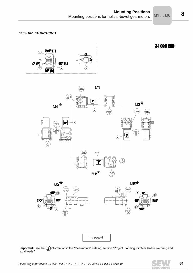
Operating Instructions – Gear Unit, R..7, F..7, K..7, S..7 Series, SPIROPLAN® W 61
8Mounting positions for helical-bevel gearmotorsMounting Positions
K167-187, KH167B-187B
* → page 51
Important: See the information in the "Gearmotors" catalog, section "Project Planning for Gear Units/Overhung and axial loads."
M1 … M6M1 … M6

62 Operating Instructions – Gear Unit, R..7, F..7, K..7, S..7 Series, SPIROPLAN® W
8 Mounting positions for helical-bevel gearmotorsMounting Positions
KF/KAF/KHF/KAZ/KHZ37-157, KVF/KVZ37-107
* → page 51
M1 … M6M1 … M6

Operating Instructions – Gear Unit, R..7, F..7, K..7, S..7 Series, SPIROPLAN® W 63
8Mounting positions for helical-bevel gearmotorsMounting Positions
KA/KH37-157, KV37-107, KT37-97
* → page 51
M1 … M6M1 … M6
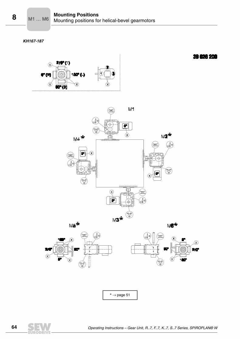
64 Operating Instructions – Gear Unit, R..7, F..7, K..7, S..7 Series, SPIROPLAN® W
8 Mounting positions for helical-bevel gearmotorsMounting Positions
KH167-187
* → page 51
M1 … M6M1 … M6

Operating Instructions – Gear Unit, R..7, F..7, K..7, S..7 Series, SPIROPLAN® W 65
8Mounting positions for helical-worm gearmotorsMounting Positions
8.7 Mounting positions for helical-worm gearmotors
S37
Important: See the information in the "Gearmotors" catalog, section "Project Planning for Gear Units/Overhung and axial loads."
M1 … M6M1 … M6

66 Operating Instructions – Gear Unit, R..7, F..7, K..7, S..7 Series, SPIROPLAN® W
8 Mounting positions for helical-worm gearmotorsMounting Positions
S47 - S97
* → page 51
Important: See the information in the "Gearmotors" catalog, section "Project Planning for Gear Units/Overhung and axial loads."
M1 … M6M1 … M6

Operating Instructions – Gear Unit, R..7, F..7, K..7, S..7 Series, SPIROPLAN® W 67
8Mounting positions for helical-worm gearmotorsMounting Positions
SF/SAF/SHF37
M1 … M6M1 … M6

68 Operating Instructions – Gear Unit, R..7, F..7, K..7, S..7 Series, SPIROPLAN® W
8 Mounting positions for helical-worm gearmotorsMounting Positions
SF/SAF/SHF/SAZ/SHZ47-97
* → page 51
M1 … M6M1 … M6

Operating Instructions – Gear Unit, R..7, F..7, K..7, S..7 Series, SPIROPLAN® W 69
8Mounting positions for helical-worm gearmotorsMounting Positions
SA/SH/ST37
M1 … M6M1 … M6

70 Operating Instructions – Gear Unit, R..7, F..7, K..7, S..7 Series, SPIROPLAN® W
8 Mounting positions for helical-worm gearmotorsMounting Positions
SA/SH/ST47-97
* → page 51
M1 … M6M1 … M6

Operating Instructions – Gear Unit, R..7, F..7, K..7, S..7 Series, SPIROPLAN® W 71
8Mounting positions for SPIROPLAN® W gearmotorsMounting Positions
8.8 Mounting positions for SPIROPLAN® W gearmotors
W10-30
M1 … M6M1 … M6
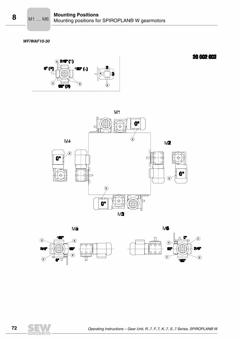
72 Operating Instructions – Gear Unit, R..7, F..7, K..7, S..7 Series, SPIROPLAN® W
8 Mounting positions for SPIROPLAN® W gearmotorsMounting Positions
WF/WAF10-30
M1 … M6M1 … M6

Operating Instructions – Gear Unit, R..7, F..7, K..7, S..7 Series, SPIROPLAN® W 73
8Mounting positions for SPIROPLAN® W gearmotorsMounting Positions
WA10-30
M1 … M6M1 … M6

74 Operating Instructions – Gear Unit, R..7, F..7, K..7, S..7 Series, SPIROPLAN® W
9 Lubricant tableLubricants
9 LubricantsGeneral information
Unless a special arrangement is made, SEW-EURODRIVE supplies the drives with alubricant fill adapted for the specific gear unit and mounting position. The decisive factoris the mounting position (M1 ... M6, → Sec. "Mounting Positions and Important OrderInformation") specified when ordering the drive. You must adapt the lubricant fill to anysubsequent changes made to the mounting position (→ Lubricant fill quantities).
9.1 Lubricant table
The lubricant table on the following page shows the permitted lubricants forSEW-EURODRIVE gear units. Please note the following key to the lubricant table.
Key to the lubricant table
Abbreviations used, meaning of shading and notes:
CLP = Mineral oil
CLP PG = Polyglycol (W gear units, conforms to USDA-H1)
CLP HC = Synthetic hydrocarbons
E = Ester oil (water pollution danger category WGK 1)
HCE = Synthetic hydrocarbons + ester oil (USDA-H1 certification)
HLP = Hydraulic oil
= Synthetic lubricant (= synthetic anti-friction bearing grease)
= Mineral lubricant (= mineral-based anti-friction bearing grease)
1) Helical-worm gear units with PG oil: Please contact SEW
2) Special lubricant for Spiroplan® gear units only
3) Recommendation: Select SEW fB ≥ 1.2
4) Pay attention to critical starting behavior at low temperatures!
5) Low-viscosity grease
6) Ambient temperature
Lubricant for the food industry (food grade oil)
Biodegradable oil (lubricant for use in agriculture, forestry and water resources)OilOil

Operating Instructions – Gear Unit, R..7, F..7, K..7, S..7 Series, SPIROPLAN® W 75
9Lubricant tableLubricants
Anti-friction bearing greases
The anti-friction bearings in gear units and motors are given a factory-fill with thegreases listed below. SEW-EURODRIVE recommends regreasing anti-friction bearingswith a grease fill at the same time as changing the oil.
Ambient temperature Manufacturer Type
Anti-friction bearing in gear unit
-20 °C ... +60 °C Mobil Mobilux EP 2
-40 °C ... +80 °C Mobil Mobiltemp SHC 100
Anti-friction bearing in motor
-20 °C ... +80 °C Esso Unirex EQ3
-20 °C ... +60 °C Shell Alvania RL3
+80 °C ... +100 °C Klüber Barrierta L55/2
-45 °C ... -25 °C Shell Aero Shell Grease 16
Special greases for anti-friction bearings in gear units:
-30 °C ... +40 °C Aral Eural Grease EP 2
-20 °C ... +40 °C Aral Aralube BAB EP2OilOil
The following grease quantities are required:
• For fast-running bearings (motor and gear unit input end): Fill the cavities betweenthe rolling elements one third full with grease.
• For slow-running bearings (in gear units and at gear unit output end): Fill the cavitiesbetween the rolling elements two thirds full with grease.

76 Operating Instructions – Gear Unit, R..7, F..7, K..7, S..7 Series, SPIROPLAN® W
9 Lubricant tableLubricants
Lubricant tableO
ilO
ilO
il
VG
22
0B
P E
ne
rgo
l
GR
-XP
22
0
VG
22
0B
P E
ne
rsy
n
SG
-XP
22
0
VG
22
0
VG
15
0
VG
15
0
VG
10
0
VG
15
0
VG
10
0
SA
E 7
5W
90
(~V
G 1
00
)
VG
22
VG
15
VG
68
-46
VG
32
BP
En
erg
ol
GR
-XP
10
0
VG
32
BP
En
erg
ol
HL
P-H
M 1
5
VG
68
0B
P E
ne
rgo
l
GR
-XP
68
0
VG
68
0B
P E
ne
rsy
n
SG
-XP
68
0
VG
46
0
VG
15
0
BP
En
erg
ol
GR
-XP
10
0
BP
En
erg
rease
LS
-EP
00
VG
22
0
VG
32
VG
46
0
VG
46
0
VG
46
0
VG
46
0
00
00
0 -
0
0+
100
+50 +40
+80
+80
+40
+40
+40
+40
+40
+40+
60
+60
-20
-20
-20
+40
-15
-20
-30
4)
4)
6)
4)
4)
4)
4)
4)
3)
2)
1)
1)
4)
4)
5)
-30
-40
-40-2
0
-25
-40
+80
+10
+10
+10
+20
-25
0
-40
0
-40
+25
-25
-20
-30
-40
-40
+10
+10
-20
-10
-50
Sta
ndard
DIN
(IS
O)
ISO
,NL
GI
CL
P(C
C)
CL
P P
G
CL
P (
CC
)
CL
P (
CC
)
CL
P H
C
HL
P (
HM
)
HL
P (
HM
)
CL
P (
CC
)
CL
P P
G
01 805 892
CL
P H
C
CL
P H
C
CL
P P
G
CL
P H
C
SE
W P
G
AP
I G
L5
CL
P P
G
DIN
51
81
8
EHC
E
R..
.
K..
.(H
K..
.)
F..
.
S..
.(H
S..
.)
R...,K
...(
HK
...)
,
F...,S
...(
HS
...)
R3
2
R3
02
W...(
HW
...)
Re
no
lin
CL
P 2
20
Op
tig
ea
r
BM
22
0M
ero
pa
22
0Tri
bo
l
11
00
/22
0
Op
tifl
ex
A
22
0
Sy
nlu
be
CL
P 2
20
Tri
bo
l
80
0/2
20
Ren
oli
n U
nis
yn
CL
P 2
20
Op
tig
ear
Syn
-th
eti
c A
220
Pin
na
cle
EP
22
0
Pin
na
cle
EP
15
0
Pin
na
cle
EP
46
0
Pin
na
cle
EP
15
0
Ra
nd
o E
P
As
hle
ss
46
Ce
tus
PA
O 4
6
Ce
tus
PA
O 4
6
Tri
bo
l
15
10
/22
0
Re
no
lin
CL
P 1
50
Op
tig
ea
r
BM
10
0M
ero
pa
15
0Tri
bo
l
11
00
/10
0
Re
no
lin
B 4
6 H
VI
Op
tig
ea
r
32
Tri
bo
l
11
00
/68
Ra
nd
o
HD
Z 1
5
Re
no
lin
CL
P 6
80
Op
tig
ea
r
BM
68
0M
ero
pa
68
0Tri
bo
l
11
00
/68
0
Sy
nlu
be
CL
P 6
80
Sy
nlu
be
CL
P 2
20
Mu
ltif
ak
68
33
EP
00
Mu
ltif
ak
EP
00
0
Tri
bo
l
80
0/6
80
Re
no
lin
CL
P 1
50
Re
no
lin
SF
7 -
04
1
Op
tig
ea
r
BM
10
0M
ero
pa
10
0Tri
bo
l
11
00
/10
0
Op
tifl
ex
A
22
0
Tri
bo
l
80
0/2
20
Op
tile
b
GT
46
0
Op
tis
yn
t
BS
46
0
Lo
ng
tim
e
PD
00
Sh
ell
Om
ala
22
0
Sh
ell
Tiv
ela
S 2
20
Sh
ell
Om
ala
HD
22
0
Sh
ell
Om
ala
HD
15
0
Sh
ell
Om
ala
10
0
Sh
ell
Te
llu
s
T 3
2
Sh
ell
Te
llu
s
T 1
5
Sh
ell
Om
ala
68
0
Sh
ell
Tiv
ela
S 6
80
Sh
ell
Tiv
ela
S 2
20
Sh
ell
Om
ala
HD
46
0
Sh
ell
Om
ala
HD
15
0
Sh
ell
Om
ala
10
0
Sh
ell C
assid
aF
luid
GL
460
Sh
ell T
ivela
GL
00
Sh
ell A
lvan
iaG
L 0
0
Ara
l D
eg
ol
BG
22
0
Ara
l D
eg
ol
GS
22
0
Ara
l D
eg
ol
PA
S 2
20
Ara
l D
eg
ol
BG
10
0
Ara
l D
eg
ol
BG
46
Ara
l D
eg
ol
BG
68
0
Ara
l D
eg
ol
BG
10
0
Ara
l D
eg
ol
BA
B 4
60
Ara
l E
ura
l
Ge
ar
46
0
Ara
lub
MF
L 0
0
Klü
be
roil
GE
M 1
-22
0
Klü
be
rsy
nth
GH
6-2
20
Klü
be
rsy
nth
EG
4-2
20
Klü
be
rsy
nth
EG
4-1
50
Klü
be
roil
GE
M 1
-15
0
Klü
be
roil
GE
M 1
-68
Klü
ber-
Su
mm
itH
yS
yn
FG
-32
Klü
ber-
Su
mm
itH
yS
yn
FG
-32
Iso
fle
x
MT
30
RO
T
Klü
be
roil
GE
M 1
-68
0
Klü
be
rsy
nth
GH
6-6
80
Klü
be
rsy
nth
EG
4-4
60
Klü
be
rsy
nth
EG
4-1
50
Klü
be
roil
GE
M 1
-15
0
Klü
be
rsy
nth
GH
6-2
20
Klü
be
rsy
nth
GE
46
-12
00
Klü
ber
SE
W
HT-4
60-5
Klü
be
rsy
nth
UH
1 6
-46
0
Klü
be
roil
4U
H1
-46
0 N
Klü
be
rbio
CA
2-4
60
Mo
bil
ge
ar
63
0
Mo
bil
Gly
go
yle
30
Mo
bil
SH
C 6
30
Mo
bil
SH
C 6
29
Mo
bil
ge
ar
62
7
Mo
bil
ge
ar
62
7
Mo
bil
D.T
.E.
13
M
Mo
bil
SH
C 6
24
Mo
bil
D.T
.E.
11
M
Mo
bil
ge
ar
63
6
Mo
bil
SH
C 6
34
Mo
bil
SH
C 6
29
Mo
bil
Gly
go
yle
30
Mo
bil
SH
C 6
24
Gly
go
yle
Gre
as
e 0
0
Mo
bil
ux
EP
00
4
Mo
bilu
be S
HC
75 W
90-L
S
°C
Mo
bil®
Oil
Oil
Sta
ndard
Sta
ndard
Sta
ndard

Operating Instructions – Gear Unit, R..7, F..7, K..7, S..7 Series, SPIROPLAN® W 77
9Lubricant fill quantitiesLubricants
9.2 Lubricant fill quantities
The specified fill quantities are recommended values. The precise values vary depend-ing on the number of stages and gear ratio. When filling, it is essential to check the oillevel plug since it indicates the precise oil capacity.
The following tables show guide values for lubricant fill quantities in relation to themounting position M1 ... M6.
Helical (R) gear units Gear unit
typeR.., R..F
Fill quantity in liters
M11) M21) M3 M4 M5 M6
R07/R07F 0.12 0.20 0.20 0.20 0.20 0.20
R17/R17F 0.25 0.55 0.35 0.55 0.35 0.35
R27/R27F 0.25/0.40 0.70 0.50 0.70 0.50 0.50
R37/R37F 0.30/0.95 0.85 0.95 1.05 0.75 0.95
R47/R47F 0.70/1.50 1.60 1.50 1.65 1.50 1.50
R57/R57F 0.80/1.70 1.90 1.70 2.10 1.70 1.70
R67/R67F 1.10/2.30 2.60/3.50 2.80 3.20 1.80 2.00
R77/R77F 1.20/3.00 3.80/4.10 3.60 4.10 2.50 3.40
R87/R87F 2.30/6.0 6.7/8.2 7.2 7.7 6.3 6.5
R97 4.60/9.8 11.7/14.0 11.7 13.4 11.3 11.7
R107 6.0/13.7 16.3 16.9 19.2 13.2 15.9
R137 10.0/25.0 28.0 29.5 31.5 25.0 25.0
R147 15.4/40.0 46.5 48.0 52.0 39.5 41.0
R167 27.0/70.0 82.0 78.0 88.0 66.0 69.0
Gear unit typeRF.. / RM..
Fill quantity in liters
M11)
1) The output end gear unit of multi-stage gear units must be filled with the larger oil volume.
M21) M3 M4 M5 M6
RF07 0.12 0.20 0.20 0.20 0.20 0.20
RF17 0.25 0.55 0.35 0.55 0.35 0.35
RF27 0.25/0.40 0.70 0.50 0.70 0.50 0.50
RF37 0.35/0.95 0.90 0.95 1.05 0.75 0.95
RF47 0.65/1.50 1.60 1.50 1.65 1.50 1.50
RF/RM57 0.80/1.70 1.80 1.70 2.00 1.70 1.70
RF/RM67 1.20/2.50 2.70/3.60 2.70 2.60 1.90 2.10
RF/RM77 1.20/2.60 3.80/4.10 3.30 4.10 2.40 3.00
RF/RM87 2.40/6.0 6.8/7.9 7.1 7.7 6.3 6.4
RF/RM97 5.1/10.2 11.9/14.0 11.2 14.0 11.2 11.8
RF/RM107 6.3/14.9 15.9 17.0 19.2 13.1 15.9
RF/RM137 9.5/25.0 27.0 29.0 32.5 25.0 25.0
RF/RM147 16.4/42.0 47.0 48.0 52.0 42.0 42.0
RF/RM167 26.0/70.0 82.0 78.0 88.0 65.0 71.0

78 Operating Instructions – Gear Unit, R..7, F..7, K..7, S..7 Series, SPIROPLAN® W
9 Lubricant fill quantitiesLubricants
Helical (RX) gear units
Parallel shaft helical (F) gear units
F.., FA..B, FH..B, FV..B:
FF..:
Gear unit typeRX..
Fill quantity in liters
M1 M2 M3 M4 M5 M6
RX57 0.60 0.80 1.30 1.30 0.90 0.90
RX67 0.80 0.80 1.70 1.90 1.10 1.10
RX77 1.10 1.50 2.60 2.70 1.60 1.60
RX87 1.70 2.50 4.80 4.80 2.90 2.90
RX97 2.10 3.40 7.4 7.0 4.80 4.80
RX107 3.90 5.6 11.6 11.9 7.7 7.7
Gear unit typeRXF..
Fill quantity in liters
M1 M2 M3 M4 M5 M6
RXF57 0.50 0.80 1.10 1.10 0.70 0.70
RXF67 0.70 0.80 1.50 1.40 1.00 1.00
RXF77 0.90 1.30 2.40 2.00 1.60 1.60
RXF87 1.60 1.95 4.90 3.95 2.90 2.90
RXF97 2.10 3.70 7.1 6.3 4.80 4.80
RXF107 3.10 5.7 11.2 9.3 7.2 7.2
Gear unit type
Fill quantity in liters
M1 M2 M3 M4 M5 M6
F..27 0.60 0.80 0.65 0.70 0.60 0.60
F..37 0.95 1.25 0.70 1.25 1.00 1.10
F..47 1.50 1.80 1.10 1.90 1.50 1.70
F..57 2.60 3.50 2.10 3.50 2.80 2.90
F..67 2.70 3.80 1.90 3.80 2.90 3.20
F..77 5.9 7.3 4.30 8.0 6.0 6.3
F..87 10.8 13.0 7.7 13.8 10.8 11.0
F..97 18.5 22.5 12.6 25.2 18.5 20.0
F..107 24.5 32.0 19.5 37.5 27.0 27.0
F..127 40.5 54.5 34.0 61.0 46.3 47.0
F..157 69.0 104.0 63.0 105.0 86.0 78.0
Gear unit type
Fill quantity in liters
M1 M2 M3 M4 M5 M6
FF27 0.60 0.80 0.65 0.70 0.60 0.60
FF37 1.00 1.25 0.70 1.30 1.00 1.10
FF47 1.60 1.85 1.10 1.90 1.50 1.70
FF57 2.80 3.50 2.10 3.70 2.90 3.00
FF67 2.70 3.80 1.90 3.80 2.90 3.20
FF77 5.9 7.3 4.30 8.1 6.0 6.3
FF87 10.8 13.2 7.8 14.1 11.0 11.2
FF97 19.0 22.5 12.6 25.6 18.9 20.5
FF107 25.5 32.0 19.5 38.5 27.5 28.0
FF127 41.5 55.5 34.0 63.0 46.3 49.0
FF157 72.0 105.0 64.0 106.0 87.0 79.0

Operating Instructions – Gear Unit, R..7, F..7, K..7, S..7 Series, SPIROPLAN® W 79
9Lubricant fill quantitiesLubricants
FA.., FH.., FV.., FAF.., FHF.., FVF.., FAZ.., FHZ.., FVZ..:
Helical-bevel (K) gear units
K.., KA..B, KH..B, KV..B:
KF..:
Gear unit type
Fill quantity in liters
M1 M2 M3 M4 M5 M6
F..27 0.60 0.80 0.65 0.70 0.60 0.60
F..37 0.95 1.25 0.70 1.25 1.00 1.10
F..47 1.50 1.80 1.10 1.90 1.50 1.70
F..57 2.70 3.50 2.10 3.40 2.90 3.00
F..67 2.70 3.80 1.90 3.80 2.90 3.20
F..77 5.9 7.3 4.30 8.0 6.0 6.3
F..87 10.8 13.0 7.7 13.8 10.8 11.0
F..97 18.5 22.5 12.6 25.2 18.5 20.0
F..107 24.5 32.0 19.5 37.5 27.0 27.0
F..127 39.0 54.5 34.0 61.0 45.0 46.5
F..157 68.0 103.0 62.0 104.0 85.0 77.0
Gear unit type
Fill quantity in liters
M1 M2 M3 M4 M5 M6
K..37 0.50 1.00 1.00 1.25 0.95 0.95
K..47 0.80 1.30 1.50 2.00 1.60 1.60
K..57 1.20 2.30 2.50 2.80 2.60 2.40
K..67 1.10 2.40 2.60 3.45 2.60 2.60
K..77 2.20 4.10 4.40 5.8 4.20 4.40
K..87 3.70 8.0 8.7 10.9 8.0 8.0
K..97 7.0 14.0 15.7 20.0 15.7 15.5
K..107 10.0 21.0 25.5 33.5 24.0 24.0
K..127 21.0 41.5 44.0 54.0 40.0 41.0
K..157 31.0 62.0 65.0 90.0 58.0 62.0
K..167 33.0 95.0 105.0 123.0 85.0 84.0
K..187 53.0 152.0 167.0 200 143.0 143.0
Gear unit type
Fill quantity in liters
M1 M2 M3 M4 M5 M6
KF37 0.50 1.10 1.10 1.50 1.00 1.00
KF47 0.80 1.30 1.70 2.20 1.60 1.60
KF57 1.30 2.30 2.70 3.15 2.90 2.70
KF67 1.10 2.40 2.80 3.70 2.70 2.70
KF77 2.10 4.10 4.40 5.9 4.50 4.50
KF87 3.70 8.2 9.0 11.9 8.4 8.4
KF97 7.0 14.7 17.3 21.5 15.7 16.5
KF107 10.0 21.8 25.8 35.1 25.2 25.2
KF127 21.0 41.5 46.0 55.0 41.0 41.0
KF157 31.0 66.0 69.0 92.0 62.0 62.0

80 Operating Instructions – Gear Unit, R..7, F..7, K..7, S..7 Series, SPIROPLAN® W
9 Lubricant fill quantitiesLubricants
KA.., KH.., KV.., KAF.., KHF.., KVF.., KAZ.., KHZ.., KVZ..:
Spiroplan® (W) gear units
The fill quantity of Spiroplan® gear units does not vary, irrespective of their mountingposition:
Helical-worm (S) gear units
S..:
SF..:
Gear unit type
Fill quantity in liters
M1 M2 M3 M4 M5 M6
K..37 0.50 1.00 1.00 1.40 1.00 1.00
K..47 0.80 1.30 1.60 2.15 1.60 1.60
K..57 1.30 2.30 2.70 3.15 2.90 2.70
K..67 1.10 2.40 2.70 3.70 2.60 2.60
K..77 2.10 4.10 4.60 5.9 4.40 4.40
K..87 3.70 8.2 8.8 11.1 8.0 8.0
K..97 7.0 14.7 15.7 20.0 15.7 15.7
K..107 10.0 20.5 24.0 32.4 24.0 24.0
K..127 21.0 41.5 43.0 52.0 40.0 40.0
K..157 31.0 66.0 67.0 87.0 62.0 62.0
KH167 33.0 95.0 105.0 123.0 85.0 84.0
KH187 53.0 152.0 167.0 200 143.0 143.0
Gear unit type Fill quantity in liters, regardless of mounting position
W..10 0.16
W..20 0.26
W..30 0.50
Gear unit type
Fill quantity in liters
M1 M2 M31)
1) The larger gear unit of multi-stage gear units must be filled with the larger oil volume.
M4 M5 M6
S37 0.25 0.40 0.50 0.55 0.40 0.40
S47 0.35 0.80 0.70/0.90 1.00 0.80 0.80
S57 .50 1.20 1.00/1.20 1.45 1.30 1.30
S67 1.00 2.00 2.20/3.10 3.10 2.60 2.60
S77 1.90 4.20 3.70/5.4 5.9 4.40 4.40
S87 3.30 8.1 6.9/10.4 11.3 8.4 8.4
S97 6.8 15.0 13.4/18.0 21.8 17.0 17.0
Gear unit type
Fill quantity in liters
M1 M2 M31)
1) The larger gear unit of multi-stage gear units must be filled with the larger oil volume.
M4 M5 M6
SF37 0.25 0.40 0.50 0.55 0.40 0.40
SF47 0.40 0.90 0.90/1.05 1.05 1.00 1.00
SF57 0.50 1.20 1.00/1.50 1.55 1.40 1.40
SF67 1.00 2.20 2.30/3.00 3.20 2.70 2.70
SF77 1.90 4.10 3.90/5.8 6.5 4.90 4.90
SF87 3.80 8.0 7.1/10.1 12.0 9.1 9.1
SF97 7.4 15.0 13.8/18.8 22.6 18.0 18.0

Operating Instructions – Gear Unit, R..7, F..7, K..7, S..7 Series, SPIROPLAN® W 81
9Lubricant fill quantitiesLubricants
SA.., SH.., SAF.., SHF.., SAZ.., SHZ..:
Gear unit type
Fill quantity in liters
M1 M2 M31)
1) The larger gear unit of multi-stage gear units must be filled with the larger oil volume.
M4 M5 M6
S..37 0.25 0.40 0.50 0.50 0.40 0.40
S..47 0.40 0.80 0.70/0.90 1.00 0.80 0.80
S..57 0.50 1.10 1.00/1.50 1.50 1.20 1.20
S..67 1.00 2.00 1.80/2.60 2.90 2.50 2.50
S..77 1.80 3.90 3.60/5.0 5.8 4.50 4.50
S..87 3.80 7.4 6.0/8.7 10.8 8.0 8.0
S..97 7.0 14.0 11.4/16.0 20.5 15.7 15.7

10
82 Operating Instructions – Gear Unit, R..7, F..7, K..7, S..7 Series, SPIROPLAN® W
Appendix
10 Appendix10.1 Index of changes
The following additions and changes have been made compared to the previous editionof the "Explosion-Proof Gear Units R..7, F..7, K..7, S..7, SPIROPLAN® W" (publicationnumber: 1055520x, edition 11/2002) operating instructions:
General additions and corrections.
Mechanical installation
• Installing the gear unit: Data on flatness error• Installing torque arms for mounted gear units: Data on retaining bolts• Mounted gear units with shrink disks: Information on assembly / removal has been
added• Mounted gear units with TorqLOC®
• AM adapter coupling: Point A
Inspection and maintenance
• Lubricant change intervals

Operating Instructions – Gear Units, R..7, F..7, K..7, S..7 Series, SPIROPLAN® W 83
11
1
2
3
4
5
6
7
8
9
10
11
13
14
15
16
17
18
19
20
21
22
11 Index
AAD inspection / maintenance 47
AD, mounting on the input shaft assembly 40
Adapter coupling 36
Adjusting the mounting position 17
AM with backstop 38
Anti-friction bearing greases 75
AQ, installing the coupling adapter 38
AQA, maintenance / inspection 47
BBackstop RS 38
Breather valve 18
CCentering shoulder AD../ZR 41
Change the oil seal 47
Check oil 46
Check oil level 46
Churning losses 51
Couplings, installation 20
Cover with backstop AD../RS 43
Cover with motor mounting platform AD../P 40
Customer service 48
DDamp locations 17
Designated use 6
EExtended storage 7
FF gear units, lubricant fill quantities 78
Flatness error 16
GGear unit inspection 46
Gear unit maintenance 46
Gear unit structure 9Gear unit venting 18
HHelical gear units, lubricant fill quantities 77, 78
helical gear units, structure 9Helical-bevel gear units, lubricant fill quantities 79
Helical-bevel gear units, structure 11
Helical-worm gear unit, structure 12
Helical-worm gear units, lubricant fill quantities 80
IIEC adapter 36
Input and output elements, installation 19
Inspection intervals 45
Inspection of AD adapter 47
Inspection of AM / AQA adapters 47
Installation tolerances 15
Installing couplings 20
Installing input and output elements 19
Installing the AM coupling adapter 36
Installing the AQ coupling adapter 38
Installing the gear unit 16
KK gear units, lubricant fill quantities 79
Keyway 23
LLubricant change intervals 45
Lubricant fill quantities 77
Lubricant fill quantities for helical gear units 77, 78
Lubricant fill quantities for helical-bevel gear units 79
Lubricant fill quantities for helical-worm gear units 80
Lubricant fill quantities for parallel shaft helical gear units78
Lubricant fill quantities for Spiroplan® gear units 80
Lubricant table 74, 76
Lubricants 74
MMaintenance / inspection 47
Maintenance intervals 45
Maintenance of AD adapter 47
Maintenance of AM / AQA adapters 47
Malfunctions 48AD input shaft assembly 49AM / AQA / AL adapters 48Gear units 48
Mechanical installation 15
Motor mounting platform 40
Mounted gear units 23, 27, 30
Mounting on the input shaft assembly AD 40
Mounting position designation 50
Mounting positionsHelical gear units 52, 55Helical-bevel gear units 60Helical-worm gear units 65Parallel shaft helical gear units 57Spiroplan® gear units 71
Mounting torque arms 21
NNameplate 14
NEMA adapter 36

11
84 Operating instructions – Gear Units, R..7, F..7, K..7, S..7 Series, SPIROPLAN® W
OOil change 46
Open air 17
PPainting gear units 18
Parallel shaft helical gear unit, structure 10
Parallel shaft helical gear units, lubricant fill quantities 78
RR gear units, lubricant fill quantities 77
RS backstop 43
RX gear units, lubricant fill quantities 78
SS gear units, lubricant fill quantities 80
Safety notes 6Serial number 14
Shrink disk 27
Solid shaft 19
Spiroplan® gear units, lubricant fill quantities 80
Spiroplan® W gear units, structure 13
Splined hollow shaft 23
Startup 44Helical, parallel shaft helical and helical-bevel gear
units 44Helical-worm and Spiroplan® W gear units 44
StructureHelical gear units 9Helical-bevel gear units 11Helical-worm gear unit 12Parallel shaft helical gear unit 10Spiroplan® gear units 13
TTorqLOC® 30
Torque arm for helical-bevel gear units 21
Torque arm for helical-worm gear units 22
Torque arm for Spiroplan® W gear units 22
Torque arms for parallel shaft helical gear units 21
Torque arms, mounting 21
Transportation 7
UUnit designation 14
WW gear units, lubricant fill quantities 80
Waste disposal 5
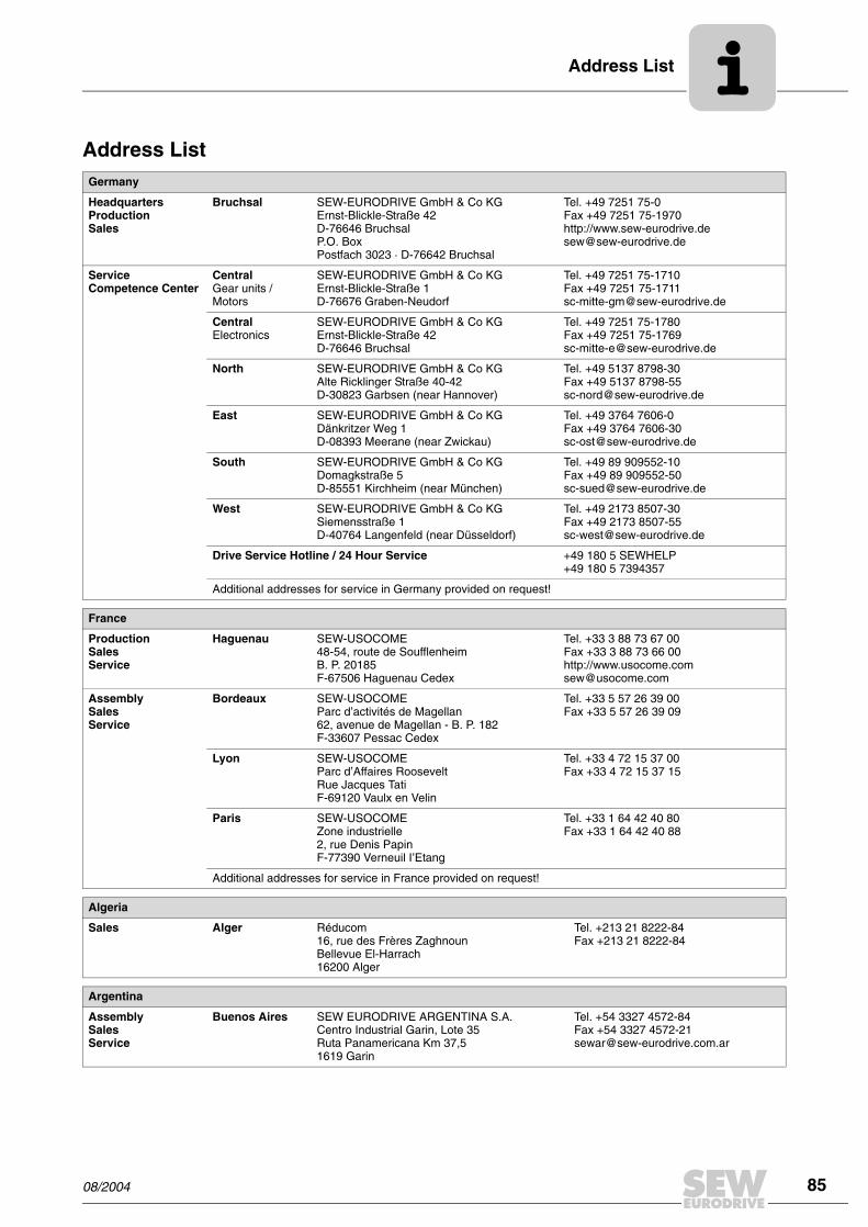
Address List
08/2004 85
Address ListGermany
HeadquartersProductionSales
Bruchsal SEW-EURODRIVE GmbH & Co KGErnst-Blickle-Straße 42 D-76646 BruchsalP.O. BoxPostfach 3023 · D-76642 Bruchsal
Tel. +49 7251 75-0Fax +49 7251 75-1970http://[email protected]
Service Competence Center
Central Gear units / Motors
SEW-EURODRIVE GmbH & Co KGErnst-Blickle-Straße 1 D-76676 Graben-Neudorf
Tel. +49 7251 75-1710Fax +49 7251 [email protected]
Central Electronics
SEW-EURODRIVE GmbH & Co KGErnst-Blickle-Straße 42 D-76646 Bruchsal
Tel. +49 7251 75-1780Fax +49 7251 [email protected]
North SEW-EURODRIVE GmbH & Co KGAlte Ricklinger Straße 40-42 D-30823 Garbsen (near Hannover)
Tel. +49 5137 8798-30Fax +49 5137 [email protected]
East SEW-EURODRIVE GmbH & Co KGDänkritzer Weg 1D-08393 Meerane (near Zwickau)
Tel. +49 3764 7606-0Fax +49 3764 [email protected]
South SEW-EURODRIVE GmbH & Co KGDomagkstraße 5D-85551 Kirchheim (near München)
Tel. +49 89 909552-10Fax +49 89 [email protected]
West SEW-EURODRIVE GmbH & Co KGSiemensstraße 1D-40764 Langenfeld (near Düsseldorf)
Tel. +49 2173 8507-30Fax +49 2173 [email protected]
Drive Service Hotline / 24 Hour Service +49 180 5 SEWHELP+49 180 5 7394357
Additional addresses for service in Germany provided on request!
France
ProductionSalesService
Haguenau SEW-USOCOME 48-54, route de Soufflenheim B. P. 20185F-67506 Haguenau Cedex
Tel. +33 3 88 73 67 00 Fax +33 3 88 73 66 00http://[email protected]
AssemblySalesService
Bordeaux SEW-USOCOME Parc d’activités de Magellan62, avenue de Magellan - B. P. 182F-33607 Pessac Cedex
Tel. +33 5 57 26 39 00Fax +33 5 57 26 39 09
Lyon SEW-USOCOME Parc d’Affaires RooseveltRue Jacques TatiF-69120 Vaulx en Velin
Tel. +33 4 72 15 37 00Fax +33 4 72 15 37 15
Paris SEW-USOCOME Zone industrielle 2, rue Denis Papin F-77390 Verneuil I’Etang
Tel. +33 1 64 42 40 80Fax +33 1 64 42 40 88
Additional addresses for service in France provided on request!
Algeria
Sales Alger Réducom 16, rue des Frères ZaghnounBellevue El-Harrach16200 Alger
Tel. +213 21 8222-84Fax +213 21 8222-84
Argentina
AssemblySalesService
Buenos Aires SEW EURODRIVE ARGENTINA S.A.Centro Industrial Garin, Lote 35Ruta Panamericana Km 37,51619 Garin
Tel. +54 3327 4572-84Fax +54 3327 [email protected]
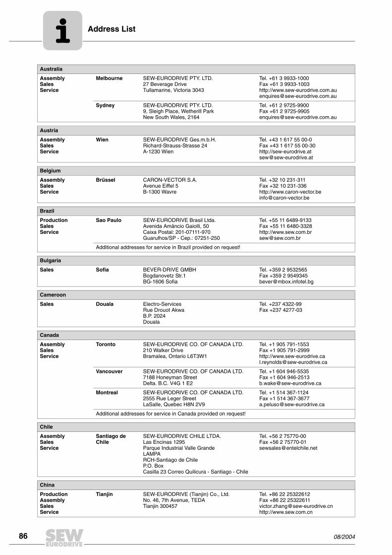
Address List
86 08/2004
Australia
AssemblySalesService
Melbourne SEW-EURODRIVE PTY. LTD.27 Beverage DriveTullamarine, Victoria 3043
Tel. +61 3 9933-1000Fax +61 3 9933-1003http://[email protected]
Sydney SEW-EURODRIVE PTY. LTD.9, Sleigh Place, Wetherill Park New South Wales, 2164
Tel. +61 2 9725-9900Fax +61 2 [email protected]
Austria
AssemblySalesService
Wien SEW-EURODRIVE Ges.m.b.H. Richard-Strauss-Strasse 24A-1230 Wien
Tel. +43 1 617 55 00-0Fax +43 1 617 55 00-30http://[email protected]
Belgium
AssemblySalesService
Brüssel CARON-VECTOR S.A.Avenue Eiffel 5B-1300 Wavre
Tel. +32 10 231-311Fax +32 10 231-336http://[email protected]
Brazil
ProductionSalesService
Sao Paulo SEW-EURODRIVE Brasil Ltda.Avenida Amâncio Gaiolli, 50Caixa Postal: 201-07111-970Guarulhos/SP - Cep.: 07251-250
Tel. +55 11 6489-9133Fax +55 11 6480-3328http://[email protected]
Additional addresses for service in Brazil provided on request!
Bulgaria
Sales Sofia BEVER-DRIVE GMBHBogdanovetz Str.1BG-1606 Sofia
Tel. +359 2 9532565Fax +359 2 [email protected]
Cameroon
Sales Douala Electro-ServicesRue Drouot AkwaB.P. 2024Douala
Tel. +237 4322-99Fax +237 4277-03
Canada
AssemblySalesService
Toronto SEW-EURODRIVE CO. OF CANADA LTD. 210 Walker Drive Bramalea, Ontario L6T3W1
Tel. +1 905 791-1553Fax +1 905 791-2999http://[email protected]
Vancouver SEW-EURODRIVE CO. OF CANADA LTD.7188 Honeyman Street Delta. B.C. V4G 1 E2
Tel. +1 604 946-5535Fax +1 604 [email protected]
Montreal SEW-EURODRIVE CO. OF CANADA LTD.2555 Rue Leger Street LaSalle, Quebec H8N 2V9
Tel. +1 514 367-1124Fax +1 514 [email protected]
Additional addresses for service in Canada provided on request!
Chile
AssemblySalesService
Santiago de Chile
SEW-EURODRIVE CHILE LTDA.Las Encinas 1295Parque Industrial Valle GrandeLAMPARCH-Santiago de ChileP.O. BoxCasilla 23 Correo Quilicura - Santiago - Chile
Tel. +56 2 75770-00Fax +56 2 [email protected]
China
ProductionAssemblySalesService
Tianjin SEW-EURODRIVE (Tianjin) Co., Ltd.No. 46, 7th Avenue, TEDA Tianjin 300457
Tel. +86 22 25322612Fax +86 22 [email protected]://www.sew.com.cn
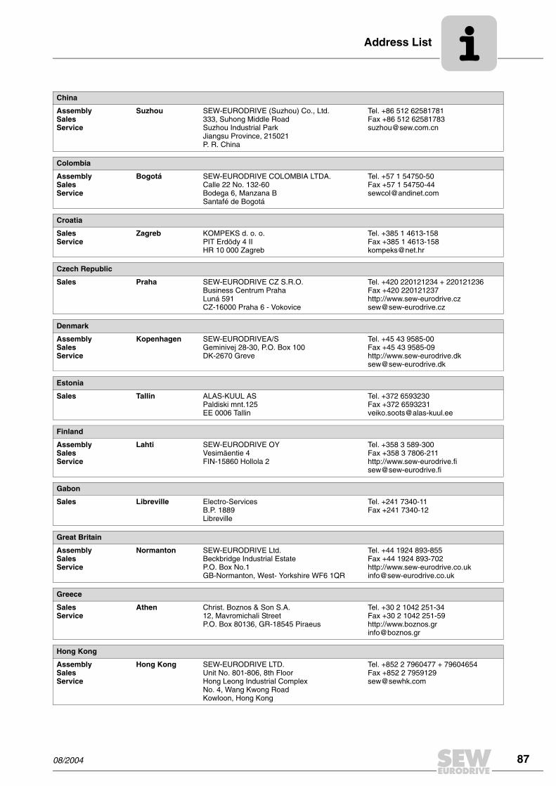
Address List
08/2004 87
AssemblySalesService
Suzhou SEW-EURODRIVE (Suzhou) Co., Ltd.333, Suhong Middle RoadSuzhou Industrial ParkJiangsu Province, 215021P. R. China
Tel. +86 512 62581781Fax +86 512 [email protected]
Colombia
AssemblySalesService
Bogotá SEW-EURODRIVE COLOMBIA LTDA. Calle 22 No. 132-60Bodega 6, Manzana BSantafé de Bogotá
Tel. +57 1 54750-50Fax +57 1 [email protected]
Croatia
SalesService
Zagreb KOMPEKS d. o. o.PIT Erdödy 4 IIHR 10 000 Zagreb
Tel. +385 1 4613-158Fax +385 1 [email protected]
Czech Republic
Sales Praha SEW-EURODRIVE CZ S.R.O.Business Centrum Praha Luná 591CZ-16000 Praha 6 - Vokovice
Tel. +420 220121234 + 220121236Fax +420 220121237http://[email protected]
Denmark
AssemblySalesService
Kopenhagen SEW-EURODRIVEA/SGeminivej 28-30, P.O. Box 100DK-2670 Greve
Tel. +45 43 9585-00Fax +45 43 9585-09http://[email protected]
Estonia
Sales Tallin ALAS-KUUL ASPaldiski mnt.125EE 0006 Tallin
Tel. +372 6593230Fax +372 [email protected]
Finland
AssemblySalesService
Lahti SEW-EURODRIVE OYVesimäentie 4FIN-15860 Hollola 2
Tel. +358 3 589-300Fax +358 3 7806-211http://[email protected]
Gabon
Sales Libreville Electro-ServicesB.P. 1889Libreville
Tel. +241 7340-11Fax +241 7340-12
Great Britain
AssemblySalesService
Normanton SEW-EURODRIVE Ltd.Beckbridge Industrial Estate P.O. Box No.1GB-Normanton, West- Yorkshire WF6 1QR
Tel. +44 1924 893-855Fax +44 1924 893-702http://[email protected]
Greece
SalesService
Athen Christ. Boznos & Son S.A.12, Mavromichali StreetP.O. Box 80136, GR-18545 Piraeus
Tel. +30 2 1042 251-34 Fax +30 2 1042 251-59http://[email protected]
Hong Kong
AssemblySalesService
Hong Kong SEW-EURODRIVE LTD.Unit No. 801-806, 8th FloorHong Leong Industrial ComplexNo. 4, Wang Kwong Road Kowloon, Hong Kong
Tel. +852 2 7960477 + 79604654Fax +852 2 [email protected]
China

Address List
88 08/2004
Hungary
SalesService
Budapest SEW-EURODRIVE Kft.H-1037 BudapestKunigunda u. 18
Tel. +36 1 437 06-58Fax +36 1 437 [email protected]
India
AssemblySalesService
Baroda SEW-EURODRIVE India Pvt. Ltd.Plot No. 4, GidcPor Ramangamdi · Baroda - 391 243Gujarat
Tel. +91 265 2831021Fax +91 265 [email protected]
Technical Offices Bangalore SEW-EURODRIVE India Private Limited308, Prestige Centre Point7, Edward RoadBangalore
Tel. +91 80 22266565Fax +91 80 [email protected]
Mumbai SEW-EURODRIVE India Private Limited312 A, 3rd Floor, Acme PlazaAndheri Kurla Road, Andheri (E)Mumbai
Tel. +91 22 28348440Fax +91 22 [email protected]
Ireland
SalesService
Dublin Alperton Engineering Ltd. 48 Moyle RoadDublin Industrial EstateGlasnevin, Dublin 11
Tel. +353 1 830-6277Fax +353 1 830-6458
Israel
Sales Tel-Aviv Liraz Handasa Ltd. Ahofer Str 34B / 22858858 Holon
Tel. +972 3 5599511Fax +972 3 [email protected]
Italy
AssemblySalesService
Milano SEW-EURODRIVE di R. Blickle & Co.s.a.s.Via Bernini,14 I-20020 Solaro (Milano)
Tel. +39 2 96 9801Fax +39 2 96 [email protected]
Ivory Coast
Sales Abidjan SICASte industrielle et commerciale pour l’Afrique165, Bld de MarseilleB.P. 2323, Abidjan 08
Tel. +225 2579-44Fax +225 2584-36
Japan
AssemblySalesService
Toyoda-cho SEW-EURODRIVE JAPAN CO., LTD 250-1, Shimoman-no,Toyoda-cho, Iwata gunShizuoka prefecture, 438-0818
Tel. +81 538 373811Fax +81 538 [email protected]
Korea
AssemblySalesService
Ansan-City SEW-EURODRIVE KOREA CO., LTD. B 601-4, Banweol Industrial Estate Unit 1048-4, Shingil-DongAnsan 425-120
Tel. +82 31 492-8051Fax +82 31 [email protected]
Latvia
Sales Riga SIA Alas-KuulKatlakalna 11CLV-1073 Riga
Tel. +371 7139386Fax +371 [email protected]
Lebanon
Sales Beirut Gabriel Acar & Fils sarlB. P. 80484Bourj Hammoud, Beirut
Tel. +961 1 4947-86 +961 1 4982-72+961 3 2745-39Fax +961 1 4949-71 [email protected]

Address List
08/2004 89
Lithuania
Sales Alytus UAB IrsevaMerkines g. 2ALT-4580 Alytus
Tel. +370 315 79204Fax +370 315 [email protected]
Luxembourg
AssemblySalesService
Brüssel CARON-VECTOR S.A.Avenue Eiffel 5B-1300 Wavre
Tel. +32 10 231-311Fax +32 10 231-336http://[email protected]
Malaysia
AssemblySalesService
Johore SEW-EURODRIVE SDN BHD No. 95, Jalan Seroja 39, Taman Johor Jaya81000 Johor Bahru, JohorWest Malaysia
Tel. +60 7 3549409Fax +60 7 [email protected]
Morocco
Sales Casablanca S. R. M.Société de Réalisations Mécaniques 5, rue Emir Abdelkader05 Casablanca
Tel. +212 2 6186-69 + 6186-70 + 6186-71Fax +212 2 [email protected]
Netherlands
AssemblySalesService
Rotterdam VECTOR Aandrijftechniek B.V. Industrieweg 175 NL-3044 AS RotterdamPostbus 10085NL-3004 AB Rotterdam
Tel. +31 10 4463-700Fax +31 10 4155-552http://[email protected]
New Zealand
AssemblySalesService
Auckland SEW-EURODRIVE NEW ZEALAND LTD. P.O. Box 58-428 82 Greenmount driveEast Tamaki Auckland
Tel. +64 9 2745627Fax +64 9 [email protected]
Christchurch SEW-EURODRIVE NEW ZEALAND LTD. 10 Settlers Crescent, FerrymeadChristchurch
Tel. +64 3 384-6251Fax +64 3 [email protected]
Norway
AssemblySalesService
Moss SEW-EURODRIVE A/SSolgaard skog 71N-1599 Moss
Tel. +47 69 241-020Fax +47 69 [email protected]
Peru
AssemblySalesService
Lima SEW DEL PERU MOTORES REDUCTORES S.A.C.Los Calderos, 120-124Urbanizacion Industrial Vulcano, ATE, Lima
Tel. +51 1 3495280Fax +51 1 [email protected]
Poland
AssemblySalesService
Lodz SEW-EURODRIVE Polska Sp.z.o.o.ul. Techniczna 5 PL-92-518 Lodz
Tel. +48 42 67710-90Fax +48 42 67710-99http://[email protected]
Portugal
AssemblySalesService
Coimbra SEW-EURODRIVE, LDA. Apartado 15 P-3050-901 Mealhada
Tel. +351 231 20 9670Fax +351 231 20 3685http://[email protected]
Romania
SalesService
Bucuresti Sialco Trading SRL str. Madrid nr.4 011785 Bucuresti
Tel. +40 21 230-1328Fax +40 21 230-7170 [email protected]

Address List
90 08/2004
Russia
Sales St. Petersburg ZAO SEW-EURODRIVE P.O. Box 263 RUS-195220 St. Petersburg
Tel. +7 812 5357142 +812 5350430Fax +7 812 5352287http://[email protected]
Senegal
Sales Dakar SENEMECA Mécanique GénéraleKm 8, Route de Rufisque B.P. 3251, Dakar
Tel. +221 849 47-70Fax +221 849 [email protected]
Serbia and Montenegro
Sales Beograd DIPAR d.o.o.Kajmakcalanska 54SCG-11000 Beograd
Tel. +381 11 3046677Fax +381 11 [email protected]
Singapore
AssemblySalesService
Singapore SEW-EURODRIVE PTE. LTD. No 9, Tuas Drive 2 Jurong Industrial Estate Singapore 638644
Tel. +65 68621701 ... 1705Fax +65 [email protected]
Slovakia
Sales Sered SEW-Eurodrive SK s.r.o.Trnavska 920SK-926 01 Sered
Tel. +421 31 7891311Fax +421 31 [email protected]
Slovenia
SalesService
Celje Pakman - Pogonska Tehnika d.o.o.UI. XIV. divizije 14SLO – 3000 Celje
Tel. +386 3 490 83-20Fax +386 3 490 [email protected]
South Africa
AssemblySalesService
Johannesburg SEW-EURODRIVE (PROPRIETARY) LIMITEDEurodrive House Cnr. Adcock Ingram and Aerodrome RoadsAeroton Ext. 2Johannesburg 2013P.O.Box 90004Bertsham 2013
Tel. +27 11 248-7000Fax +27 11 [email protected]
Capetown SEW-EURODRIVE (PROPRIETARY) LIMITED Rainbow ParkCnr. Racecourse & Omuramba RoadMontague GardensCape TownP.O.Box 36556Chempet 7442 Cape Town
Tel. +27 21 552-9820Fax +27 21 552-9830Telex 576 [email protected]
Durban SEW-EURODRIVE (PROPRIETARY) LIMITED2 Monaceo PlacePinetownDurbanP.O. Box 10433, Ashwood 3605
Tel. +27 31 700-3451Fax +27 31 [email protected]
Spain
AssemblySalesService
Bilbao SEW-EURODRIVE ESPAÑA, S.L. Parque Tecnológico, Edificio, 302E-48170 Zamudio (Vizcaya)
Tel. +34 9 4431 84-70Fax +34 9 4431 [email protected]
Sweden
AssemblySalesService
Jönköping SEW-EURODRIVE ABGnejsvägen 6-8S-55303 JönköpingBox 3100 S-55003 Jönköping
Tel. +46 36 3442-00Fax +46 36 3442-80http://[email protected]

Address List
08/2004 91
Switzerland
AssemblySalesService
Basel Alfred lmhof A.G.Jurastrasse 10 CH-4142 Münchenstein bei Basel
Tel. +41 61 41717-17Fax +41 61 41717-00http://[email protected]
Thailand
AssemblySalesService
Chon Buri SEW-EURODRIVE (Thailand) Ltd.Bangpakong Industrial Park 2700/456, Moo.7, Tambol DonhuarohMuang DistrictChon Buri 20000
Tel. +66 38 454281Fax +66 38 [email protected]
Tunisia
Sales Tunis T. M.S. Technic Marketing Service7, rue Ibn EI Heithem Z.I. SMMT2014 Mégrine Erriadh
Tel. +216 1 4340-64 + 1 4320-29Fax +216 1 4329-76
Turkey
AssemblySalesService
Istanbul SEW-EURODRIVE Hareket Sistemleri Sirketi Bagdat Cad. Koruma Cikmazi No. 3 TR-34846 Maltepe ISTANBUL
Tel. +90 216 4419163 + 216 4419164 + 216 3838014Fax +90 216 [email protected]
USA
ProductionAssemblySalesService
Greenville SEW-EURODRIVE INC. 1295 Old Spartanburg Highway P.O. Box 518Lyman, S.C. 29365
Tel. +1 864 439-7537Fax Sales +1 864 439-7830Fax Manuf. +1 864 439-9948Fax Ass. +1 864 439-0566Telex 805 550 http://[email protected]
AssemblySalesService
San Francisco SEW-EURODRIVE INC. 30599 San Antonio St.Hayward, California 94544-7101
Tel. +1 510 487-3560Fax +1 510 [email protected]
Philadelphia/PA SEW-EURODRIVE INC. Pureland Ind. Complex 2107 High Hill Road, P.O. Box 481Bridgeport, New Jersey 08014
Tel. +1 856 467-2277Fax +1 856 [email protected]
Dayton SEW-EURODRIVE INC.2001 West Main Street Troy, Ohio 45373
Tel. +1 937 335-0036Fax +1 937 [email protected]
Dallas SEW-EURODRIVE INC.3950 Platinum Way Dallas, Texas 75237
Tel. +1 214 330-4824Fax +1 214 [email protected]
Additional addresses for service in the USA provided on request!
Venezuela
AssemblySalesService
Valencia SEW-EURODRIVE Venezuela S.A.Av. Norte Sur No. 3, Galpon 84-319Zona Industrial Municipal NorteValencia, Estado Carabobo
Tel. +58 241 832-9804Fax +58 241 [email protected]@cantv.net

How we’re driving the world
With people who
think fast and
develop the
future with you.
With a worldwide
service network that is
always close at hand.
With drives and controls
that automatically
improve your productivity.
With comprehensive
knowledge in virtually
every branch of
industry today.
With uncompromising
quality that reduces the
cost and complexity of
daily operations.
With a global presence
that offers responsive
and reliable solutions.
Anywhere.
With innovative
technology that solves
tomorrow’s problems
today.
With online information
and software updates, via
the Internet, available
around the clock.
Gearmotors \ Industrial Gear Units \ Drive Electronics \ Drive Automation \ Services
SEW-EURODRIVEDriving the world
SEW-EURODRIVE GmbH & Co KG
P.O. Box 3023 · D-76642 Bruchsal / Germany
Phone +49 7251 75-0 · Fax +49 7251 75-1970
www.sew-eurodrive.com

AC Motors DR/DV/DT/DTE/DVEAsynchronous Servomotors CT/CV
Edition
02/2003
Operating Instructions1056 7917 / EN

SEW-EURODRIVE

Operating Instructions – AC Motors, Asynchronous Servomotors 3
Contents
1 Important Notes................................................................................................. 4
2 Safety Notes ...................................................................................................... 5
3 Motor Design ..................................................................................................... 63.1 Configuration principles of AC motors ...................................................... 63.2 Nameplate, unit designation ..................................................................... 7
4 Mechanical Installation..................................................................................... 94.1 Before you begin....................................................................................... 94.2 Preliminary work ....................................................................................... 94.3 Installing the motor.................................................................................. 104.4 Installation tolerances ............................................................................. 11
5 Electrical Installation ...................................................................................... 125.1 Wiring notes ............................................................................................ 125.2 Special aspects for operation with a frequency inverter ......................... 125.3 Special aspects of single-phase motors ................................................. 125.4 Special aspects of torque motors and low-speed motors ....................... 135.5 Special aspects in switching operation ................................................... 135.6 Connecting the motor.............................................................................. 145.7 Preparing motor sizes 56 and 63 ............................................................ 155.8 Connecting motor DT56...+/BMG............................................................ 155.9 Single-phase version ET56..................................................................... 165.10 Connecting the motor using the IS plug connector ................................. 165.11 Connecting the motor using plug connectors AS.. and AM.. .................. 205.12 Connecting the motor using ASK1 plug connector ................................. 205.13 Connecting the brake.............................................................................. 225.14 Accessory equipment.............................................................................. 23
6 Startup.............................................................................................................. 276.1 Prerequisites for startup.......................................................................... 276.2 Altering the blocking direction on motors with backstop ......................... 28
7 Malfunctions .................................................................................................... 297.1 Motor faults ............................................................................................. 297.2 Brake faults ............................................................................................. 307.3 Faults when operating with a frequency inverter .................................... 30
8 Inspection and Maintenance .......................................................................... 318.1 Inspection and maintenance periods ...................................................... 318.2 Preliminary work for motor and brake maintenance ............................... 328.3 Inspection and maintenance work on the motor ..................................... 358.4 Inspection and maintenance of the brake BMG02.................................. 378.5 Inspection and maintenance of the brake BR03 ..................................... 388.6 Inspection and maintenance of the brakes BM15-62, BMG05-122 ........ 42
9 Technical Data................................................................................................. 479.1 Work done, braking torques BMG02....................................................... 479.2 Information for ordering a replacement BMG02...................................... 479.3 Work done, working air gap, braking torques BR03, BMG05-8 .............. 489.4 Work done, working air gap, braking torques BM15 - 62, BMG61/122... 499.5 Operating currents .................................................................................. 509.6 Permitted ball bearing types ................................................................... 549.7 Lubricant table for anti-friction bearings of SEW motors......................... 54
10 Revision Status ............................................................................................... 55
00
I
Pi
fkVA
Hz
n

1
4
1 Important NotesSafety and warn-ing instructions
Always follow the safety and warning instructions contained in this publication!
A requirement of fault-free operation and fulfillment of any rights to claim under guaran-tee is that you adhere to the information in the operating instructions. Consequently,read the operating instructions before you start operating the drive!
The operating instructions contain important information about service; as a result, theyshould be kept in the vicinity of the unit.
Waste disposal This product consists of:
• Iron
• Aluminum
• Copper
• Plastic
• Electronics components
Please dispose of the parts in accordance with the applicable regulations.
Electrical hazardPossible consequences: Severe or fatal injuries.
Hazard Possible consequences: Severe or fatal injuries.
Hazardous situationPossible consequences: Slight or minor injuries.
Harmful situationPossible consequences: Damage to the drive and the environment.
Tips and useful information.
Operating Instructions – AC Motors, Asynchronous Servomotors

2
2 Safety NotesPreliminary remarks
The following safety notes are principally concerned with the use of motors. When op-erating geared motors, please also refer to the safety notes for gear units in the corre-sponding operating instructions.
Please also pay attention to the supplementary safety notes in the individual sec-tions of these operating instructions.
General informa-tion
During and after operation, motors and geared motors have live and moving parts andtheir surfaces may be hot.
All work related to transportation, putting into storage, setting up/mounting, con-nection, startup, maintenance and repair should only be performed by trainedpersonnel observing
• the corresponding detailed operating instructions and wiring diagrams,
• the warning and safety signs on the motor/geared motor,
• the specific regulations and requirements for the system and
• national/regional regulations governing safety and the prevention of accidents.
Severe injuries and damage to property may result from
• incorrect use,
• incorrect installation or operation,
• removal of required protective covers or the housing when this is not permitted.
Designated use These electric motors are intended for industrial systems. They comply with the applica-ble standards and regulations and meet the requirements of the Low Voltage Directive73/23/EEC.
The technical data and the information about permitted conditions can be found on thenameplate and in the documentation.
It is essential to observe all specified information!
Transportation Inspect the shipment for any damage in transit as soon as you receive the deliv-ery. Inform the shipping company immediately. It may be necessary to precludestartup.
Tighten screwed in transport lugs firmly. They are only designed for the weight of themotor/geared motor; do not attach any additional loads.
The installed lifting eyebolts are in accordance with DIN 580. The loads and regu-lations specified in that document must always be observed. If the geared motoris equipped with two suspension eye lugs or lifting eyebolts, then both of the sus-pension eye lugs should be used for transportation. In this case, the tension forcevector of the slings must not exceed a 45° angle in accordance with DIN 580.
Use suitable, sufficiently rated handling equipment if necessary. Remove any transpor-tation fixtures prior to startup.
Installation/mounting
Follow the instructions in Sec. 'Mechanical Installation!'
Inspection and maintenance
Follow the instructions in Sec. 'Inspection and Maintenance!'
Operating Instructions – AC Motors, Asynchronous Servomotors
5
3
6
onfiguration principles of AC motors
3 Motor Design
3.1 Configuration principles of AC motors
Key
The following illustration is intended to explain the general structure. Its purpose is onlyto make it easier to assign components to the spare parts lists. Discrepancies are pos-sible depending on the motor size and version!
02969AXX
10
7
1112
1
20 44 41
16
42
36
35
37
32
13
22
132131
112111
129
130 115113
119
123
116118
117
2107
106
9
100101
103
3
31
135
134
1 Rotor, cpl. 31 Key 107 Oil flinger 131 Sealing washer
2 Circlip 32 Circlip 111 Seal 132 Terminal box cover
3 Key 35 Fan guard 112 Terminal box lower part 134 Screw plug
7 Flanged end shield 36 Fan 113 Machine screw 135 Sealing washer
9 Screw plug 37 V-ring 115 Terminal board
10 Circlip 41 Equalizing ring 116 Terminal yoke
11 Grooved ball bearing 42 B bearing end shield 117 Hex head screw
12 Circlip 44 Grooved ball bearing 118 Lock washer
13 Hex head screw (tie rod) 100 Hex nut 119 Machine screw
16 Stator, cpl. 101 Lock washer 123 Hex head screw
20 Nilos ring 103 Stud 129 Screw plug
22 Hex head screw 106 Oil seal 130 Sealing washer
C
Operating Instructions – AC Motors, Asynchronous Servomotors

3Nameplate, unit designation
3.2 Nameplate, unit designation
Nameplate
Example: Brake motor DFV 160 M4 /BM
Unit designation
Examples: AC(brake)motors DR/DT/DV/DTE/DVE
Example: Factory number
03214AXX
06150AEN
05156AEN
DFV 160 M 4 /BM01.3001234568.0001.0011 S1
220 - 240 / 380 - 415 Y
240 -266 / 415 - 460 Y
∆∆
1440 / 1740230 AC
109
B50.83
39.0 / 22.535.5 / 20.555 F
BGE1.5150
01. 301234568. 0001. 00
Manufacturer’s last two year number digits (2 digits)
Serial number (4 digits)
Order number (10 digits)
Sales organization
Operating Instructions – AC Motors, Asynchronous Servomotors
7
3
8
ameplate, unit designation
Nameplate
Example: Servo brake motor CT90L4 / BMG / TF / ES1S
Unit designation
Examples: Servo (brake) motors CT/CV
Example: Factory number
51358AXX
05158AEN
CT90L4 BMG TF / ES1S
01.3410069302.0001.00
30.5
3000 10.5
103 345 7.9
B5 28 54 F
230~ 20 BGE 1.5
05161AEN
N
Operating Instructions – AC Motors, Asynchronous Servomotors
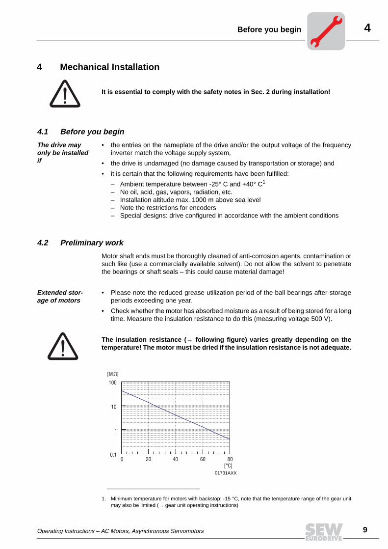
4Before you begin
4 Mechanical Installation
4.1 Before you begin
The drive may only be installed if
• the entries on the nameplate of the drive and/or the output voltage of the frequencyinverter match the voltage supply system,
• the drive is undamaged (no damage caused by transportation or storage) and
• it is certain that the following requirements have been fulfilled:
– Ambient temperature between -25° C and +40° C1
– No oil, acid, gas, vapors, radiation, etc.– Installation altitude max. 1000 m above sea level– Note the restrictions for encoders– Special designs: drive configured in accordance with the ambient conditions
4.2 Preliminary work
Motor shaft ends must be thoroughly cleaned of anti-corrosion agents, contamination orsuch like (use a commercially available solvent). Do not allow the solvent to penetratethe bearings or shaft seals – this could cause material damage!
Extended stor-age of motors
• Please note the reduced grease utilization period of the ball bearings after storageperiods exceeding one year.
• Check whether the motor has absorbed moisture as a result of being stored for a longtime. Measure the insulation resistance to do this (measuring voltage 500 V).
The insulation resistance (→ following figure) varies greatly depending on thetemperature! The motor must be dried if the insulation resistance is not adequate.
It is essential to comply with the safety notes in Sec. 2 during installation!
1. Minimum temperature for motors with backstop: -15 °C, note that the temperature range of the gear unitmay also be limited (→ gear unit operating instructions)
01731AXX
100
10
1
0,10 20 40 60 80
[°C]
[M ]
Operating Instructions – AC Motors, Asynchronous Servomotors
9
4
10
nstalling the motor
Drying the motor Heat up the motor
• with hot air or
• using an isolation transformer
– connect the windings in series (→ following figure)– auxiliary AC voltage supply max. 10% of the rated voltage with max. 20% of the
rated current
The drying process is finished when the minimum insulation resistance has been ex-ceeded.
Check the terminal box to see whether
• the inside is clean and dry,
• the connections and fastening parts are free from corrosion,
• the joint seals are ok,
• the cable screw fittings are tight, otherwise clean or replace them.
4.3 Installing the motor
The motor or geared motor may only be mounted or installed in the specified mountingposition on a level and torsionally rigid support structure which is not subject to shocks.
Carefully align the motor and the driven machine to avoid placing any unacceptablestrain on the output shafts (observe permitted overhung load and axial thrust data!).
Do not butt or hammer the shaft extension.
Use an appropriate cover to protect motors in vertical mounting positions fromobjects or fluids entering (protection cowl C).
Ensure an unobstructed cooling air supply and that air heated by other apparatus cannotbe drawn in or reused.
Balance components for subsequent mounting on the shaft with a half key (motor shaftsare balanced with a half key).
Any condensation drain holes will be sealed by plastic plugs and should only beopened when necessary; open condensation drain holes are not permitted, sincethis invalidates higher classes of enclosure.
For brake motors with manual brake release, screw in either the hand lever (with self-reengaging manual brake release) or setscrew (with lockable manual brake release).
Note the following for encoder mounting:
Foot-mounted motors CT/DT71, CT/DT(E)90, CV/DV(E)132M, CV/DV(E)160L must bemounted on supports because the radius of the cover is greater than the shaft height.
For foot-mounted (brake)motors of sizes DTE90L and DVE132M, the shaft height is thatof the next larger IEC standard motor (100 mm or 160 mm). The foot dimensions of theDTE90, DVE180 and DVE225 motors deviate from the IEC dimensions, see section"Notes on dimension sheets" in the Geared Motors catalog.
01730AEN
Transformer
I
Operating Instructions – AC Motors, Asynchronous Servomotors

4Installation tolerances
Installation in damp areas or in the open
If possible, arrange the terminal box so the cable entries are pointing downwards.
Coat the threads of cable screw fittings and pocket caps with sealant and tighten themwell – then coat them again.
Seal the cable entry well.
Thoroughly clean the sealing surfaces of terminal boxes and terminal box covers priorto reassembly; gaskets must be glued in on one side. Fit new gaskets to replace brittleones!
Restore the anticorrosive coating if necessary.
Check the enclosure.
4.4 Installation tolerances
Shaft end Flanges
Diameter tolerance in accordance with DIN 748• ISO k6 at Ø ≤ 50 mm• ISO m6 at Ø > 50 mm• Center bore in accordance with DIN 332, shape
DR..
Centering shoulder tolerance in accordance with DIN 42948• ISO j6 at Ø ≤ 230 mm• ISO h6 at Ø > 230 mm
Operating Instructions – AC Motors, Asynchronous Servomotors
11
5
12
iring notes
5 Electrical InstallationIt is essential to comply with the safety notes in Sec. 2 during installation!
Switch contacts in utilization category AC-3 to EN 60947-4-1 must be used forswitching the motor and the brake.
5.1 Wiring notes
Comply with the safety notes during installation.
Protection against interfer-ence from brake control systems
Do not route brake cables alongside switched-mode power cables, since otherwisethere is a risk of disrupting brake controllers.
Switched-mode power cables include, in particular:
– Output cables from frequency and servo controllers, converters, soft start units andbrake units
– Connecting harnesses to braking resistors, etc.
Protection against interfer-ence from motor protection devices
To provide protection against interference from SEW motor protection devices (temper-ature sensors TF, winding thermostats TH):
– Route separately shielded feeder cables together with switched-mode power lines inone cable
– Do not route unshielded feeder cables together with switched-mode power lines inone cable
5.2 Special aspects for operation with a frequency inverter
When motors are powered by inverters, you must adhere to the wiring instructions is-sued by the inverter manufacturer. It is essential to pay close attention to the operatinginstructions for the frequency inverter.
5.3 Special aspects of single-phase motors
Bear in mind that SEW single-phase motors are supplied without accessory equipmentsuch as capacitors, starting relays or centrifugal switches (exception: ET56L4 → Sec.'Single-phase version ET56'). Any parts you need must be obtained from your dealerand connected according to the corresponding instructions and wiring diagrams.
W
Operating Instructions – AC Motors, Asynchronous Servomotors

5Special aspects of torque motors and low-speed motors
5.4 Special aspects of torque motors and low-speed motors
Due to the design of torque motors and low-speed motors, very high induction voltagesmay be generated when they are switched off. Consequently, we recommend protectionusing the varistor circuit shown below. The size of the varistors depends, among otherfactors, on the starting frequency – note for project planning!
5.5 Special aspects in switching operation
When the motors are used in switching operation, any possible malfunctions of theswitchgear must be excluded by appropriate wiring. According to EN 60204 (electricalequipment of machines), motor windings must have interference suppression in orderto protect the numerical or programmable logic controllers. Since it is primarily switchingoperations which lead to the disruptions, we recommend installing protective circuitry onthe switching devices.
01732CXX
U
U1
U U
V1 W1
Operating Instructions – AC Motors, Asynchronous Servomotors
13
5
14
onnecting the motor
5.6 Connecting the motor
Connecting the motor via termi-nal boxes
• According to the wiring diagram provided
• Check the cross sections of cables
• Arrange terminal links correctly
• Tighten screw connections and protective earth conductors firmly
• In terminal boxes: Check winding connections and tighten them if necessary
Small connection parts
Please note: In the case of motor sizes DR63 - DV132S, the small connection parts(connection nuts for feeder cables, terminal links, lock washer and washers) are sup-plied in a bag. Depending on the type of terminal board, install the parts in accordancewith the figure below. In the connection on the right in the figure below, the second re-taining nut, the lock washer and the washer are not used. The external connection (6)can be installed directly or as a lug (4) below the terminal washer (5).
In case of operation with electronic control units, it is essential to adhere to the corre-sponding operating instructions/wiring diagrams!
50926AXX
1 Terminal stud 1 Terminal stud
2 Lock washer 2 Hex nut with flange
3 Terminal washer 3 Terminal link
4 Motor terminal lead 4 Motor with Stock connection terminal
5 Top nut 5 Terminal washer
6 Washer 6 External connection
7 External connection
8 Bottom nut
1
1
2
3
4
5
6
2
3
4
5
6
7
8
The asynchronous servomotors of the CT/CV series will be shipped with switched ter-minal links according to the nameplate.
C
Operating Instructions – AC Motors, Asynchronous Servomotors

5Preparing motor sizes 56 and 63
5.7 Preparing motor sizes 56 and 63
Important: Wear safety glasses – danger of injury from fragments!
• Put on the terminal box cover and tighten screws
• Define which cable entries to open
• Open the cable entries
– with a chisel or similar (hold at an angle)– by tapping lightly with a hammer
Caution – Do not punch through into the inside of the terminal box!
• Open the terminal box, remove any pieces that may have broken off
• Secure the cable screw fittings with the supplied lock nuts
5.8 Connecting motor DT56...+/BMG
The motor has a star point with three fixed connection points in the winding overhang.The power supply leads (L1, L2, L3) are connected to a spring cage terminal block (2)in the terminal box (1). The brake BMG02 is controlled using the brake rectifier BG1.2(3). As an alternative, the brake can be controlled from the switch cabinet using BM se-ries rectifiers.
01733AXX
04861AXX
V WUTF TF
1
2
3
Operating Instructions – AC Motors, Asynchronous Servomotors
15
5
16
ingle-phase version ET56
5.9 Single-phase version ET56
The single-phase motor ET56 is supplied with a mounted and connected running capac-itor :
1~230 V, 50 Hz CB = 4 µF
1~230 V, 60 Hz CB = 4 µF
1~110 V, 60 Hz CB = 20 µF
5.10 Connecting the motor using the IS plug connector
The IS plug connector is supplied with its base fully wired-up, including additional fea-tures such as a brake rectifier. The upper section of the IS connector is included in thescope of delivery and must be connected as shown in the wiring diagram.
The IS plug connection has CSA approval up to 600 V. (Note for application accordingto CSA regulations: Tighten the M3 terminal screws to a torque of 0.5 Nm! See the fol-lowing table for American Wire Gauge (AWG) line cross sections!)
Line cross sec-tion
Make sure the type of line corresponds to the applicable regulations. The rated currentsare specified on the motor nameplate. The line cross sections that can be used are listedin the following table.
No full-load startup is possible with the running capacitor alone! The single-phase motor cannot be combined with a TF.
03075AXX
Without variable termi-nal link
With variable termi-nal link
Link cable Double assignment(motor and brake/SR)
0.25 - 4.0 mm2 0.25 - 2.5 mm2 max. 1.5 mm2 max. 1 x 2.5 and 1 x 1.5 mm2
23 - 12 # AWG 23 - 14 # AWG max. 16 # AWG max. 1 x 14 # and 1 x 16 # AWG
S
Operating Instructions – AC Motors, Asynchronous Servomotors

5Connecting the motor using the IS plug connector
Wiring the upper section of the plug connector
• Loosen the housing cover screws
– Remove the housing cover
• Remove the screws from the upper section of the plug connector
– Remove the upper section of the plug connector from the cover
• Strip the insulation off the connection lead
– Strip about 9 mm insulation off the connecting leads
• Pass the cable through the cable screw fitting
Wiring as shown in wiring diagram DT82, DT83
• Connect the lines as shown in the wiring diagram
– Tighten the clamping screws carefully!
• Install the plug connector (→ Sec. 'Installing the plug connector')
Wiring as shown in wiring diagram DT81
For / startup:
• Connect with six lines
– Tighten the clamping screws carefully!– Motor contactors in the switch cabinet
• Install the plug connector (→ Sec. 'Installing the plug connector')
For or operation:
• Connect as shown in the wiring diagram
• Install the variable terminal link as shown in the following figures according to desiredmotor operation (m or W)
• Install the plug connector (→ Sec. 'Installing the plug connector')
01734AXX 01735AXX
Operating Instructions – AC Motors, Asynchronous Servomotors
17
5
18
onnecting the motor using the IS plug connector
Brake control sys-tem BSR – prepar-ing the variable ter-minal link
For operation:
On the W side of the variable terminal link as shown in the following figure: Remove onlythe bare metal pin of the marked prong horizontally – touch guard!
For operation:
On the m side of the variable terminal link as shown in the following figure: Completelyremove two prongs horizontally.
Wiring according to the DT81 wiring diagram for W or m operation with dou-ble terminal assignment
• At terminal point for double assignment:
– Connect the link cable
• When operation is as required:
– Insert the link cable in the variable terminal link
• Install the variable terminal link
• At terminal point for double assignment:
– Connect the motor lead above the variable terminal link
• Connect the other lines as shown in the wiring diagram
• Install the plug connector (→ Sec. 'Installing the plug connector')
50429AXX
50430AXX
01738AXX
C
Operating Instructions – AC Motors, Asynchronous Servomotors

5Connecting the motor using the IS plug connector
Installing the plug connector
The housing cover of the IS plug connector can be screwed onto the lower section ofthe plug connector depending on the required position of the cable lead. The upper sec-tion of the plug connector shown in the following figure must first be installed in the hous-ing cover so it will match the position of the lower section of the plug connector:
• Define the required mounting position
• Install the upper section of the plug connector into the housing cover in accordancewith the mounting position
• Close the plug connector
• Tighten the cable screw fitting
Mounting position of the upper section of the plug connector in the housing cover
01739AXX
01740AXX
Operating Instructions – AC Motors, Asynchronous Servomotors
19
5
20
onnecting the motor using plug connectors AS.. and AM..
5.11 Connecting the motor using plug connectors AS.. and AM..
Plug connectors AS.. or AM.. are mounted on the side of the terminal box. They are fas-tened onto the terminal box either with two clips as in the AMA1, AMB1 and ASB1 orwith one clip as in the AMD1, AME1, ASD1 and ASE1.
The ASD1 and ASE1 types with single clip closure correspond to the DESINA regulationissued by the Association of German Machine Tool Manufacturers (VDW).
The ASA1 / ASD1 or ASB1 / ASE1 and the AMA1 / AMD1 are supplied with their basesfully wired up, including additional features such as a brake rectifier.
The customer is responsible for obtaining the upper sections of the connectorsfrom the dealer and connecting them in accordance with the wiring diagrams(supplied with the motor).
5.12 Connecting the motor using ASK1 plug connector
Drives with ASK1 plug connector are certified according to the ECOFAST specification(version 1.1). Switchgear or control units which also have to be certified can be connect-ed to SEW-EURODRIVE motors using a pre-fabricated system cable or a carrier plate(installation integrated in the motor → Fig. B). The ASK1 plug connector with single-cliplocking is mounted on the side of the terminal box and fully wired, including additionalfeatures such as a brake rectifier.
50956AXX
AMA1ASE1
®
51081AXX
ASK1
A B
ASK1
2
11
ECOcertifiedFAST
C
Operating Instructions – AC Motors, Asynchronous Servomotors

5Connecting the motor using ASK1 plug connector
Position of the plug connector
Possible positions of the ASK1 plug connector are "X" (= standard position), "1", "2" or"3." Unless specified otherwise, the unit is supplied with the plug connector in position"3." For installation integrated into the motor (using the carrier plate), units are suppliedwith the plug connector in position "3" only.
Installing the car-rier plate
• Loosen and remove four retaining screws (1) below the terminal box (→ Fig. A)
• Place the carrier plate (2) against the bores for the retaining screws and install it bytightening the four retaining screws (1) (→ Fig. B)
• The system cable pre-fabricated according to the ECOFAST specification mustbe obtained from a specialist retailer by the customer.
• For installation integrated in the motor according to the ECOFAST specifica-tion, the customer must obtain the carrier plate from SEW-EURODRIVE byquoting part number 0187 390 3. Carrier plates from other manufacturers donot fit on SEW-EURODRIVE motors.
51083AXX
1
X
3
2ASK1
Operating Instructions – AC Motors, Asynchronous Servomotors
21
5
22
onnecting the brake
5.13 Connecting the brake
The brake is released electrically. The brake is applied mechanically when the voltageis switched off.
• Connect the brake according to the wiring diagram supplied with the brake.
• Note: In view of the DC voltage to be switched and the high level of current load, itis essential to use either special brake contactors or AC contactors with contacts inutilization category AC-3 to EN 60947-4-1.
• If necessary, for version with manual brake release you can install
– hand lever (for manually disengaging brake)– or manual brake release screw (for fixing brake in the disengaged position)
• After a new brake disk has been fitted, the maximum braking torque will be achievedafter a few cycles.
Connecting the brake control system
The DC disk brake is powered from a brake control system with protection circuit. Thiscontrol is accommodated in the terminal box / IS lower part or must be installed in theswitch cabinet (→ Sec. 'Wiring notes').
• Check the line cross sections - braking currents (→ Sec. 'Technical Data')
• Connect the brake control system according to the wiring diagram supplied with thebrake
• For motors in thermal classification H, install the brake rectifier in the switch cabinet!
Comply with the applicable regulations issued by the relevant employer’s liabilityinsurance association regarding phase failure protection and the associated cir-cuit/circuit modification!
C
Operating Instructions – AC Motors, Asynchronous Servomotors

5Accessory equipment
5.14 Accessory equipment
Connect supplied accessory equipment according to the wiring diagrams included.
Temperature sensor TF
The positive temperature coefficient (PTC) thermistors comply with DIN 44082.
Resistance measurement (measuring instrument with V ≤ 2.5 V or I < 1 mA):
• Standard measured values: 20...500 Ω, thermal resistance > 4000 Ω• Measured values pole-changing with separate winding: 40...1000 Ω,
thermal resistance > 4000 Ω
Winding thermostats THThe thermostats are connected in series as standard and open when the permittedwinding temperature is exceeded. They can be connected in the drive monitoring loop.
Forced cooling fan
Motor size 71 - 132S
Do not apply any voltage!
VAC VDC
Voltage V [V] 250 400 60 24
Current (cos ϕ = 1.0) [A]
2.5 0.75 1.0 1.6
Current (cos ϕ = 0.6) [A]
1.6 0.5
Contact resistance max. 1 ohm at 5 V = / 1 mA
VS System
• 1 x 230 VAC, 50 Hz
• Connection in separate terminal box
• Max. connection cross section 3 x 1.5 mm2
• Cable screw fitting M16x1.5
Please refer to the VS wiring diagram for information about connecting the VS system(order number: 0975 8385).
Operating Instructions – AC Motors, Asynchronous Servomotors
23
5
24
ccessory equipment
The VR forced cooling fan is available for 24 V DC voltage and for 100 ... 240 V ACvoltage.
The AC voltage type includes a VR forced cooling fan and the UWU51A switch-modepower supply (→ following figure).
• Input: 100 ... 240 VAC -6% / +10%, 50/60 Hz
• Output: 24 VDC -1% / +2%, 1.25 A
• Connection: Screw terminals 0.2 ... 2.5 mm2, separable
• Enclosure: IP20; attachment to EN 50022 DIN rail in the switch cabinet
VR System
• 24 VDC ± 20 %
• Connection via plug connector
• Max. connection cross section 3x1 mm2
• Cable screw fitting Pg7 with inside diameter 7 mm
50990AXX
50919AXX
1
2-
+24V DC
77
3884,5
74,5
Please refer to the VR wiring diagram for information about connecting the VR forcedcooling fan (order number: 0880 3198)
A
Operating Instructions – AC Motors, Asynchronous Servomotors

5Accessory equipment
Motor size 132M - 280
.
A transformer may be present in the VS system in order to adapt to a voltage other thanthe standard. VS and V systems are also available for 60 Hz
Encoder over-view
V system
• 3 x 400 VAC, 50 Hz
• Connection in separate terminal box
• Max. connection cross section 4 x 1.5 mm2
• Cable screw fitting M16x1.5
Please refer to the VS or V wiring diagram for information about connecting the VS andV systems (order no: 0975 8385).
Enco-der
for SEW motor Type of encoder ShaftSpecifica-
tionSupply Signal
EH1T1)
DR63... Encoder Hollow shaft -
5 VDC regulated 5 VDC TTL/RS-422
EH1S2)
24 VDC
1 Vss sin/cos
EH1R 5 VDC TTL/RS-422
EH1C 24 VDC HTL
ES1T1)
CT/DT/CV/DV71...100DTE/DVE90...100
Encoder
Spread shaft
-
5 VDC regulated 5 VDC TTL/RS-422
ES1S2)
24 VDC
1 Vss sin/cos
ES1R 5 VDC TTL/RS-422
ES1C 24 VDC HTL
ES2T1)
CV/DV(E)112...132S
5 VDC regulated 5 VDC TTL/RS-422
ES2S2)
24 VDC
1 Vss sin/cos
ES2R 5 VDC TTL/RS-422
ES2C 24 VDC HTL
EV1T1)
CT/CV71...200DT/DV71...280
DTE/DVE90...225Solid shaft
5 VDC regulated 5 VDC TTL/RS-422
EV1S2)
24 VDC
1 Vss sin/cos
EV1R 5 VDC TTL/RS-422
EV1C 24 VDC HTL
NV11
DT/DV71...132DTE/DVE90...132S Proximity sensor Solid shaft
A track
24 VDC
1 pulse/revolution, NO contactNV21 A+B track
NV12 A track 2 pulses/revolution, NO contactNV22 A+B track
NV16 A track 6 pulses/revolution, NO contactNV26 A+B track
AV1Y CT/CV71...200DT/DV71...280
DTE/DVE90...225
Absolute encoderSolid shaft -
15/24 VDCMSSI interface and
1 Vss sin/cos
AV1H3) HIPERFACE® encoder 12 VDC
RS485 interface and 1 Vss sin/cos
1) recommended encoder for operation with MOVITRAC® 31C
2) recommended encoder for operation with MOVIDRIVE®
3) recommended encoder for operation with MOVIDRIVE® compact
Operating Instructions – AC Motors, Asynchronous Servomotors
25
5
26
ccessory equipment
• Refer to the following wiring diagrams for information about connecting ES1./ES2./EV1. /EH1. encoders and AV1Y / AV1H absolute encoders:
• Wiring diagram ES1./ES2./EV1./EH1. encoder: Order number 0918 6832• Wiring diagram AV1Y absolute encoder: Order number 0918 6808• Wiring diagram AV1H absolute encoder: Order number 1052 9705
Encoder connec-tion
When connecting the encoders to the inverters, always follow the operating instructionsfor the relevant inverter!
• Maximum line length (inverter - encoder):
– 100 m with a capacitance per unit length ≤ 120 nF/km
• Core cross section: 0.20...0.5 mm2
• Use a shielded cable with twisted pairs of insulated conductors (exception: cable forHTL sensor) and connect the shield over a large surface area at both ends:
– to the encoder in the cable screw fitting or in the encoder plug– to the inverter on the electronics shield clamp or to the housing of the sub D plug
• Route the encoder cables separately from the power cables, maintaining a gap of atleast 200 mm.
Maximum vibration load for encoders ≤ 10g ≈ 100 m/s2
A
00
I
Operating Instructions – AC Motors, Asynchronous Servomotors

6Prerequisites for startup
6 Startup
6.1 Prerequisites for startup
Before startup, make sure that
• the drive is undamaged and not blocked,
• the measures stipulated in the 'Preliminary work' section are performed after extend-ed storage,
• all connections have been made properly,
• the direction of rotation of the motor/geared motor is correct
– (motor rotating clockwise: U, V, W to L1, L2, L3),
• all protective covers have been fitted correctly,
• all motor protection equipment is active and set for the rated motor current,
• in the case of hoist drives, the self-reengaging manual brake release is used,
• there are no other sources of danger present.
During startup, make sure that
• the motor is running correctly (no overload, no speed fluctuation, no loud noises,etc.),
• the correct braking torque is set according to the specific application (→ Sec. 'Tech-nical data').
• in case of problems (→ Sec. 'Malfunctions').
It is essential to comply with the safety notes in Sec. 2 during startup!
In brake motors with self-reengaging manual brake release, the manual brake re-lease lever must be removed after startup. A bracket is provided for storing it onthe outside of the motor.
Operating Instructions – AC Motors, Asynchronous Servomotors
00
I
27

6
28
ltering the blocking direction on motors with backstop
6.2 Altering the blocking direction on motors with backstop
Dimension 'x' after installation
Do not start up the motor in the blocking direction (note the phase angle whenconnecting). Note the direction of rotation of the output shaft and the number of stageswhen mounting the motor on a gear unit. The backstop can be operated once in theblocking direction at half the motor voltage for checking purposes.
1. Isolate the motor from supply, safeguarding it against unintentional power-up.
2. Remove the fan guard (1) and the fan (2); remove the machine screws (3).
3. Remove the V-ring (4) and sealing flange with felt ring (5). (Collect the grease forsubsequent use.)
4. Remove the circlip (6) (not with DT71/80); in addition for DV132M-160M: remove theequalizing rings (10).
5. Pull the carrier (8) and wedge element train (9) completely off via the tapped bores(7), turn them by 180° and press them back on.
6. Refill the grease.
7. Important: Do not exert pressure on or hit the wedge element train – danger ofdamaging the material!
8. During the press-in operation – shortly before the wedge element penetrates thelocking collar – slowly turn the rotor shaft by hand in the direction of rotation. Thisallows the wedge element to slide into the locking collar more easily.
9. Install the remaining parts of the backstop by following steps 4. to 2. in reverse order.Note the installation dimension 'x' for the V-ring (4).
50447AXX
6107
1243589
X
Motor Dimension 'x' after instal-lation
DT71/DT80 6.7 mm
DT(E)90/DV(E)100 9.0 mm
DV(E)112/132S 9.0 mm
DV(E)132M - 160M 11.0 mm
DV(E)160L - 225 11.0 mm
DV250 - 280 13.5 mm
A
Operating Instructions – AC Motors, Asynchronous Servomotors

7Motor faults
7 Malfunctions
7.1 Motor faults
Fault Possible cause Remedy
Motor does not start up Interruption in connecting harness Check connections, correct if necessary
Brake does not release → Sec. 'Brake faults'
Fuse blown Replace fuse
Motor protection has tripped Check motor protection is set correctly, rectify any fault
Motor contactor does not switch, fault in control
Check motor contactor control, rectify any fault
Motor does not start or only with difficulty
Motor designed for delta connection but used in star connection
Correct circuit
Voltage and frequency deviate markedly from setpoint, at least during switch-on
Provide better power supply system; check cross section of connecting harness
Motor does not start in star connection, only in delta connection
Torque not sufficient in star connection Switch on directly if delta inrush current is not too great; otherwise use a larger motor or a special version (contact SEW)
Contact fault on star delta switch Rectify fault
Incorrect direction of rotation Motor connected incorrectly Swap over two phases
Motor hums and has high current consumption
Brake does not release → Sec. 'Brake faults'
Winding defective Send motor to specialist workshop for repair
Rotor rubbing
Fuses blow or motor protec-tion trips immediately
Short circuit in line Rectify short circuit
Short circuit in motor Send motor to specialist workshop for repair
Lines connected incorrectly Correct circuit
Ground fault on motor Send motor to specialist workshop for repair
Severe speed loss under load
Overload Perform power measurement, use larger motor or reduce load if necessary
Voltage drops Increase cross section of connecting harness
Motor heats up excessively (measure temperature)
Overload Perform power measurement, use larger motor or reduce load if necessary
Inadequate cooling Correct cooling air supply or clear cooling air passages, retrofit forced cooling fan if necessary
Ambient temperature too high Adhere to permitted temperature range
Use delta connection for motor rather than star connection as provided for
Correct circuit
Loose contact in connecting harness (one phase missing)
Rectify loose contact
Fuse blown Look for and rectify cause (see above); replace fuse
Supply voltage deviates from rated motor voltage by more than 5%. A higher voltage has a particularly unfavorable effect in motors with low-speed winding since in these, the no-load current is already close to the rated current even when the voltage is normal.
Adapt motor to supply voltage
Rated operating mode (S1 to S10, DIN 57530) exceeded, e.g. due to excessive starting frequency
Adapt rated operating mode of motor to required operat-ing conditions; if necessary call in a specialist to deter-mine what is the correct drive
Excessively loud Ball bearing compressed, contaminated or damaged
Re-align motor, inspect ball bearing (→ Sec. 'Permitted ball bearing types') and replace if necessary (→ Sec. 'Lubricant table for anti-friction bearings of SEW motors')
Vibration of rotating parts Rectify cause, possibly imbalance
Foreign bodies in cooling air passages Clean the cooling air passages
Operating Instructions – AC Motors, Asynchronous Servomotors
29
7
30
rake faults
7.2 Brake faults
7.3 Faults when operating with a frequency inverter
The symptoms described in Sec. 'Motor faults' may also occur when the motor is oper-ated with a frequency inverter. Please refer to the frequency inverter operating instruc-tions for the significance of the problems which occur and to find information about rec-tifying the problems.
Customer service
Fault Possible cause Remedy
Brake does not release Incorrect voltage on brake control unit Apply correct voltage
Brake control unit failed Fit a new brake control system, check internal resistance and insulation of brake coil, check switchgear
Max. permitted working air gap exceeded because brake lining worn down
Measure and set working air gap
Voltage drop along connecting harness > 10%
Provide for correct connection voltage; check cable cross section
Inadequate cooling, brake overheats Replace type BG brake rectifier with type BGE
Brake coil has interturn fault or short circuit to exposed conductive part
Replace complete brake and brake control system (spe-cialist workshop), check switchgear
Motor does not brake Working air gap not correct Measure and set working air gap
Brake lining worn down Replace entire brake disk
Incorrect braking torque Change the braking torque (→ Sec. 'Technical data')• by the type and number of brake springs• Brake BMG 05: by installing the same brake coil body
design as in the BMG 1 brake• Brake BMG 2: by installing the same brake coil body
design as in the BMG 4 brake
BM(G) only: Working air gap so large that set-ting nuts come into contact
Set the working air gap
BR03, BM(G) only: Manual brake release device not set correctly
Adjust setting nuts
Brake is applied with time lag
Brake is switched on AC voltage side Switch on DC and AC voltage sides (e.g. BSR); please refer to wiring diagram
Noises in vicinity of brake Gearing wear caused by jolting startup Check project planning
Pulsating torques due to incorrectly set fre-quency inverter
Check/correct setting of frequency inverter according to operating instructions
Please provide the following information if you require the assistance of our customer service department:• Nameplate data (complete)• Nature and extent of the fault• Time and peripheral circumstances of the fault• Presumed cause
B
Operating Instructions – AC Motors, Asynchronous Servomotors
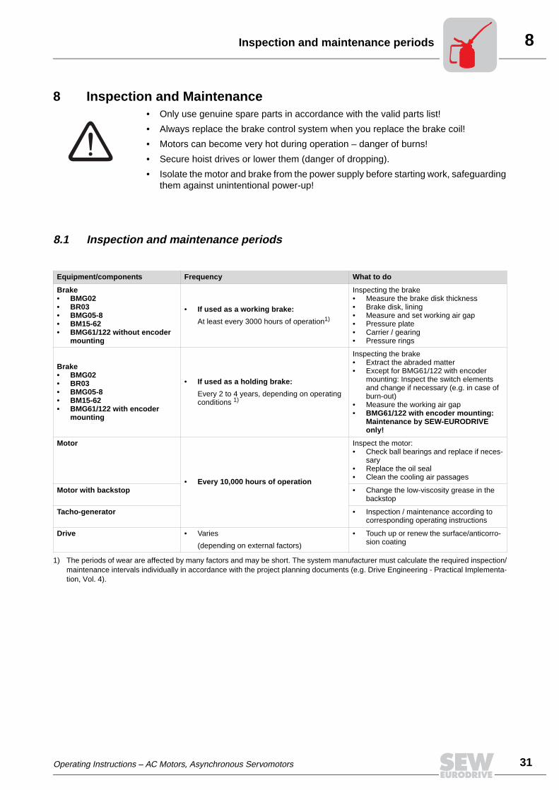
8Inspection and maintenance periods
8 Inspection and Maintenance• Only use genuine spare parts in accordance with the valid parts list!
• Always replace the brake control system when you replace the brake coil!
• Motors can become very hot during operation – danger of burns!
• Secure hoist drives or lower them (danger of dropping).
• Isolate the motor and brake from the power supply before starting work, safeguardingthem against unintentional power-up!
8.1 Inspection and maintenance periods
Equipment/components Frequency What to do
Brake• BMG02• BR03• BMG05-8• BM15-62• BMG61/122 without encoder
mounting
• If used as a working brake:
At least every 3000 hours of operation1)
Inspecting the brake• Measure the brake disk thickness• Brake disk, lining• Measure and set working air gap• Pressure plate• Carrier / gearing• Pressure rings
Brake• BMG02• BR03• BMG05-8• BM15-62• BMG61/122 with encoder
mounting
• If used as a holding brake:
Every 2 to 4 years, depending on operating conditions 1)
Inspecting the brake• Extract the abraded matter• Except for BMG61/122 with encoder
mounting: Inspect the switch elements and change if necessary (e.g. in case of burn-out)
• Measure the working air gap• BMG61/122 with encoder mounting:
Maintenance by SEW-EURODRIVE only!
Motor
• Every 10,000 hours of operation
Inspect the motor:• Check ball bearings and replace if neces-
sary• Replace the oil seal• Clean the cooling air passages
Motor with backstop • Change the low-viscosity grease in the backstop
Tacho-generator • Inspection / maintenance according to corresponding operating instructions
Drive • Varies
(depending on external factors)
• Touch up or renew the surface/anticorro-sion coating
1) The periods of wear are affected by many factors and may be short. The system manufacturer must calculate the required inspection/maintenance intervals individually in accordance with the project planning documents (e.g. Drive Engineering - Practical Implementa-tion, Vol. 4).
Operating Instructions – AC Motors, Asynchronous Servomotors
31
8
32
reliminary work for motor and brake maintenance
8.2 Preliminary work for motor and brake maintenance
Removing the incremental encoder EV1. / absolute encoder AV1H
Key
• Remove the hood cover or fan guard (361). If a forced cooling fan is fitted, remove itfirst.
• Remove the machine screw (366) from the intermediate flange and remove the coverplate (369).
• Unscrew the clamping hub connection of the coupling.
• Loosen machine screws (232) and turn the conical spring washers (251) outwards.
• Remove the encoder (220) together with the coupling (233).
• Lever off the intermediate flange (236) after removing the screws (234).
Note:
During re-assembly, make sure the runout of the shaft end is ≤ 0.05 mm.
Isolate the motor and brake from the power supply before starting work, safe-guarding them against unintentional power-up!
51322AXX 51324AXX
Removal of EV1. / AV1H on motors up to size 225 Removal of EV1. / AV1H on motors from size 250 upwards
361
220
EV1.
AV1.
369
232251366233236
234 369 251 232 361234703
366236 233550
EV1.
AV1.
220
220 Encoder 236 Intermediate flange 369 Cover plate
232 Machine screw 251 Conical spring washer 550 Brake
233 Coupling 361 Hood cover / fan guard 703 Hex head screw
234 Hex head screw 366 Machine screw
P
Operating Instructions – AC Motors, Asynchronous Servomotors

8Preliminary work for motor and brake maintenance
Removing the incremental encoder ES1. / ES2.
Key
ES1. / ES2. • Remove the hood cover (361).
• Loosen the retaining screws (733) for the torque arm.
• Open the screw cover on the back wall of the encoder (220).
• Unscrew the central retaining screw (367) by about 2 – 3 turns and loosen the coneby tapping lightly on the head of the screw. Then unscrew the retaining screw andpull off the encoder.
EH1. • Unscrew the central retaining screws [3] and remove encoder.
Note:
During re-assembly:
– Apply NOCO® fluid to the encoder spigot [1] or shaft end [2].
– Tighten the central retaining screw (367) to 2.9 Nm.
51341AXX
367733 220 3611
ES1. / ES2. EH1.
2 3
220 Encoder 361 Hood cover
367 Retaining screw 733 Retaining screw for the torque arm
Operating Instructions – AC Motors, Asynchronous Servomotors
33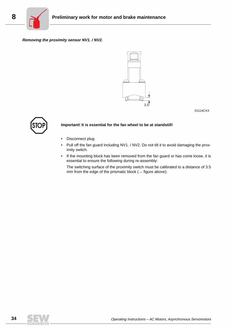
8
34
reliminary work for motor and brake maintenance
Removing the proximity sensor NV1. / NV2.
• Disconnect plug
• Pull off the fan guard including NV1. / NV2. Do not tilt it to avoid damaging the prox-imity switch.
• If the mounting block has been removed from the fan guard or has come loose, it isessential to ensure the following during re-assembly:
The switching surface of the proximity switch must be calibrated to a distance of 3.5mm from the edge of the prismatic block (→ figure above).
01114CXX
Important! It is essential for the fan wheel to be at standstill!
3.5
P
Operating Instructions – AC Motors, Asynchronous Servomotors

8Inspection and maintenance work on the motor
8.3 Inspection and maintenance work on the motor
Example: Motor DFT90
Key
50922AXX
12
3
45
67
8
9
10 11 12
13
14
16
17
18
1
20
9
15
1 Circlip 8 Circlip 15 Hex head screw
2 Oil flinger 9 Rotor 16 V-ring
3 Oil seal 10 Nilos ring 17 Fan
4 Screw plug 11 Ball bearing 18 Circlip
5 Drive end bearing bracket
12 Equalizing ring 19 Fan guard
6 Circlip 13 Stator 20 Housing screw
7 Ball bearing 14 Non drive end bearing bracket
Operating Instructions – AC Motors, Asynchronous Servomotors
35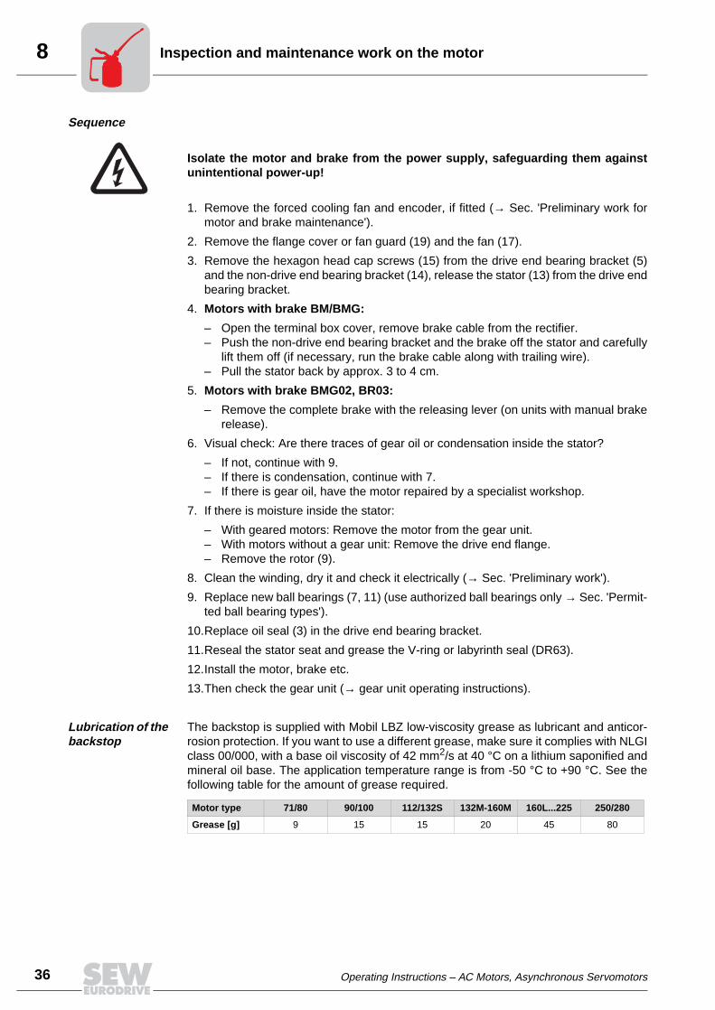
8
36
nspection and maintenance work on the motor
Sequence
1. Remove the forced cooling fan and encoder, if fitted (→ Sec. 'Preliminary work formotor and brake maintenance').
2. Remove the flange cover or fan guard (19) and the fan (17).
3. Remove the hexagon head cap screws (15) from the drive end bearing bracket (5)and the non-drive end bearing bracket (14), release the stator (13) from the drive endbearing bracket.
4. Motors with brake BM/BMG:
– Open the terminal box cover, remove brake cable from the rectifier.– Push the non-drive end bearing bracket and the brake off the stator and carefully
lift them off (if necessary, run the brake cable along with trailing wire).– Pull the stator back by approx. 3 to 4 cm.
5. Motors with brake BMG02, BR03:
– Remove the complete brake with the releasing lever (on units with manual brakerelease).
6. Visual check: Are there traces of gear oil or condensation inside the stator?
– If not, continue with 9.– If there is condensation, continue with 7.– If there is gear oil, have the motor repaired by a specialist workshop.
7. If there is moisture inside the stator:
– With geared motors: Remove the motor from the gear unit.– With motors without a gear unit: Remove the drive end flange.– Remove the rotor (9).
8. Clean the winding, dry it and check it electrically (→ Sec. 'Preliminary work').
9. Replace new ball bearings (7, 11) (use authorized ball bearings only → Sec. 'Permit-ted ball bearing types').
10.Replace oil seal (3) in the drive end bearing bracket.
11.Reseal the stator seat and grease the V-ring or labyrinth seal (DR63).
12.Install the motor, brake etc.
13.Then check the gear unit (→ gear unit operating instructions).
Lubrication of the backstop
The backstop is supplied with Mobil LBZ low-viscosity grease as lubricant and anticor-rosion protection. If you want to use a different grease, make sure it complies with NLGIclass 00/000, with a base oil viscosity of 42 mm2/s at 40 °C on a lithium saponified andmineral oil base. The application temperature range is from -50 °C to +90 °C. See thefollowing table for the amount of grease required.
Isolate the motor and brake from the power supply, safeguarding them againstunintentional power-up!
Motor type 71/80 90/100 112/132S 132M-160M 160L...225 250/280
Grease [g] 9 15 15 20 45 80
I
Operating Instructions – AC Motors, Asynchronous Servomotors

8Inspection and maintenance of the brake BMG02
8.4 Inspection and maintenance of the brake BMG02
Measure the brake disk thick-ness, replace brake BMG02
The status of the brake disk is determined by measuring the brake disk thickness. Re-place the brake BMG02 when the brake disk thickness reaches the minimum value (→figure below). It is not possible to adjust the working air gap.
1. Isolate the motor and brake from the power supply, safeguarding them againstunintentional power-up!
2. Remove the hand lever (1, on units with manual brake release). Remove the fanguard and the fan.
3. Loosen the screws (2) and remove the complete brake with the releasing lever (onunits with manual brake release)
4. Measure the thickness 'd' of the brake disk (3):
5. Replace the complete brake when the brake disk thickness has reached theminimum value.
6. Mount the complete brake on the motor:
– Make sure that the gearing of the brake disk (4) engages in the gearing of the car-rier (5).
– Route the electric brake leads through the non drive-end bearing bracket and theinside of the motor into the terminal box.
7. Use bolts (2) to fit the brake back onto the non drive-end bearing bracket.
8. Re-install the fan, fan guard and hand lever (1) (on units with manual brake release).
50345AXX
Brake Thickness 'd' of the brake disk [mm] Max. braking torque
Type max. min. [Nm]
BMG02 6 5.45.6
0.81.2
1
2
d
5 4 3
Operating Instructions – AC Motors, Asynchronous Servomotors
37
8
38
nspection and maintenance of the brake BR03
8.5 Inspection and maintenance of the brake BR03
Key
50067AXX
4
5
5
6
12
7
3
8
9
10
12 11
13
151617
18
12
14
1 Carrier 7 Brake disk 13 Hand lever
2 Clip 8 Pressure plate with stud 14 Releasing lever
3 Circlip 9 Damping plate 15 Sealing washer
4 Friction plate 10 Brake springs 16 Lock nut
5 Bolt 11 Brake coil body 17 Conical coil spring
6 Guide ring 12 Bolt 18 Sealing element
I
Operating Instructions – AC Motors, Asynchronous Servomotors
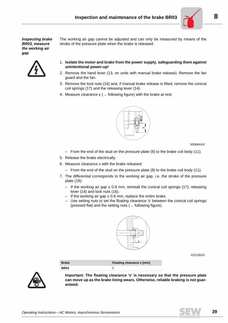
8Inspection and maintenance of the brake BR03
Inspecting brake BR03, measure the working air gap
The working air gap cannot be adjusted and can only be measured by means of thestroke of the pressure plate when the brake is released.
1. Isolate the motor and brake from the power supply, safeguarding them againstunintentional power-up!
2. Remove the hand lever (13, on units with manual brake release). Remove the fanguard and the fan.
3. Remove the lock nuts (16) and, if manual brake release is fitted, remove the conicalcoil springs (17) and the releasing lever (14).
4. Measure clearance x (→ following figure) with the brake at rest:
– From the end of the stud on the pressure plate (8) to the brake coil body (11).
5. Release the brake electrically.
6. Measure clearance x with the brake released:
– From the end of the stud on the pressure plate (8) to the brake coil body (11).
7. The differential corresponds to the working air gap, i.e. the stroke of the pressureplate (18):
– If the working air gap ≤ 0.8 mm, reinstall the conical coil springs (17), releasinglever (14) and lock nuts (16).
– If the working air gap ≥ 0.8 mm, replace the entire brake.– Use setting nuts to set the floating clearance 's' between the conical coil springs
(pressed flat) and the setting nuts (→ following figure).
Important: The floating clearance 's' is necessary so that the pressure platecan move up as the brake lining wears. Otherwise, reliable braking is not guar-anteed.
50066AXX
01111BXX
Brake Floating clearance s [mm]
BR03 2
X
s
Operating Instructions – AC Motors, Asynchronous Servomotors
39
8
40
nspection and maintenance of the brake BR03
8. Reassemble the removed parts. Connect the new brake (replaced if the working airgap ≥ 0.8 mm) to the motor (→ following figure):
– Make sure the gearing of the brake disk engages in the gearing of the carrier andthat the plug on the motor end fits into the socket on the brake end.
Altering the brak-ing torque BR03
The braking torque can be changed in steps (→ Sec. 'Work done, working air gap, brak-ing torques of brake BR03, BMG05-8')
• by installing different brake springs.
• by changing the number of brake springs.
1. Isolate the motor and brake from the power supply, safeguarding them againstunintentional power-up!
2. Remove the hand lever (13, on units with manual brake release). Remove the fanguard and the fan.
3. Loosen the bolts (12) and remove the complete brake with the releasing lever (onunits with manual brake release).
4. Loosen the screws (5) and remove the guide ring (6) with friction plate (4), brake disk(7), pressure plate (8) and damping plate (9).
5. Remove the brake springs (10) from the brake coil body (11) and replace them bynew ones.
6. Position the new brake springs symmetrically.
7. Slide the damping plate (9) over two studs attached to the pressure plate (8) so theembossing pattern is located with the projecting side facing the pressure plate.
8. Pressure plate (8):
– Place on the brake springs (10) together with the damping plate (9).– Guide the studs attached to the pressure plate (8) through the holes in the brake
coil body (6) and make sure the pressure plate is in the correct position.
9. Place the flat side of the brake disk (7) on the pressure plate (8).
Note: Do not bring the disk into contact with grease or oil!
10.Place the guide ring (6) and friction disk (4) onto the brake disk (7), press down andinstall the screws (5).
50175AXX
I
Operating Instructions – AC Motors, Asynchronous Servomotors

8Inspection and maintenance of the brake BR03
11.Units with manual brake release:
– Put on the conical coil springs (17) and releasing lever (14), install the lock nuts(16).
– With manual brake release: Use setting nuts to set the floating clearance 's' be-tween the conical coil springs (pressed flat) and the setting nuts (→ following fig-ure).
Important: The floating clearance 's' is necessary so that the pressure platecan move up as the brake lining wears. Otherwise, reliable braking is not guar-anteed.
12.Connect the complete brake back onto the motor (→ following figure):
– Make sure the gearing of the brake disk engages in the gearing of the carrier andthat the plug on the motor end fits into the socket on the brake end.
13.Re-install the fan, fan guard and hand lever (10) (on units with manual brake re-lease).
01111BXX
Brake Floating clearance s [mm]
BR03 2
50175AXX
s
Operating Instructions – AC Motors, Asynchronous Servomotors
41
8
42
nspection and maintenance of the brakes BM15-62, BMG05-122
8.6 Inspection and maintenance of the brakes BM15-62, BMG05-122
Brake BM(G)05-15
Brakes BMG61 / BMG122 with encoder mounting are only used as holding brakes.Maintenance work by SEW-EURODRIVE only.
50923AXX
1
23
4
5
67
8
9
10
a
bc
11 12 1314
1516
1718
19
20
21
22
e
I
Operating Instructions – AC Motors, Asynchronous Servomotors

8Inspection and maintenance of the brakes BM15-62, BMG05-122
20
Brakes BM30-62, BMG61/122
Key
50920AXX
2 3 5
6
1a
7
7b
1
8
1
1213
1415
16
1718
19
10
a
d
e
1 Motor with brake bearing bracket 8 Pressure plate 14 Dowel pin1a BMG61/122 only: 9 Damping plate (BMG only) 15 Release lever with hand lever
Intermediate flange 10a Stud (3 pcs.) 16 Stud (2 pcs.)
2 Carrier 10b Counter spring 17 Conical coil spring3 Circlip 10c Pressure ring 18 Setting nut4 Niro disk (BMG only) 10d Setting sleeve 19 Fan
5 Rubber sealing collar 10e Hex nut 20 Circlip6 Annular spring 11 Brake spring 21 Fan guard
7 Brake disk 12 Brake coil body 22 Housing screw7b BM 32, 62 only: 13 In BMG: Seal
Brake stationary disk, annular spring,
In BM: V-ring
Brake disk
Operating Instructions – AC Motors, Asynchronous Servomotors
43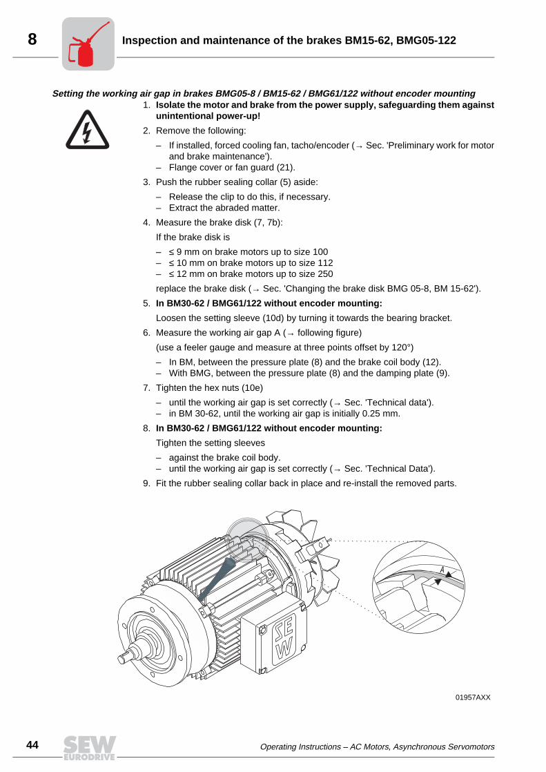
8
44
nspection and maintenance of the brakes BM15-62, BMG05-122
Setting the working air gap in brakes BMG05-8 / BM15-62 / BMG61/122 without encoder mounting1. Isolate the motor and brake from the power supply, safeguarding them against
unintentional power-up!
2. Remove the following:
– If installed, forced cooling fan, tacho/encoder (→ Sec. 'Preliminary work for motorand brake maintenance').
– Flange cover or fan guard (21).
3. Push the rubber sealing collar (5) aside:
– Release the clip to do this, if necessary.– Extract the abraded matter.
4. Measure the brake disk (7, 7b):
If the brake disk is
– ≤ 9 mm on brake motors up to size 100– ≤ 10 mm on brake motors up to size 112– ≤ 12 mm on brake motors up to size 250
replace the brake disk (→ Sec. 'Changing the brake disk BMG 05-8, BM 15-62').
5. In BM30-62 / BMG61/122 without encoder mounting:
Loosen the setting sleeve (10d) by turning it towards the bearing bracket.
6. Measure the working air gap A (→ following figure)
(use a feeler gauge and measure at three points offset by 120°)
– In BM, between the pressure plate (8) and the brake coil body (12).– With BMG, between the pressure plate (8) and the damping plate (9).
7. Tighten the hex nuts (10e)
– until the working air gap is set correctly (→ Sec. 'Technical data').– in BM 30-62, until the working air gap is initially 0.25 mm.
8. In BM30-62 / BMG61/122 without encoder mounting:
Tighten the setting sleeves
– against the brake coil body.– until the working air gap is set correctly (→ Sec. 'Technical Data').
9. Fit the rubber sealing collar back in place and re-install the removed parts.
01957AXX
A
.
I
Operating Instructions – AC Motors, Asynchronous Servomotors

8Inspection and maintenance of the brakes BM15-62, BMG05-122
Fitting a new brake disk in brakes BMG05-8 / BM15-62 / BMG61/122 without encoder mountingWhen fitting a new brake disk (in BMG05-4 ≤ 9 mm; in BMG62 ≤ 10 mm; in BMG61/122≤ 12 mm) inspect the other removed parts as well and fit new ones if necessary.
1. Isolate the motor and brake from the power supply, safeguarding them againstunintentional power-up!
2. Remove the following:
– If installed, forced cooling fan, tacho/encoder (→ Sec. 'Preliminary work for motorand brake maintenance').
– Flange cover or fan guard (21), circlip (20) and fan (19).
3. Remove the rubber sealing collar (5) and the manual brake release:
– Setting nuts (18), conical coil springs (17), studs (16), release lever (15), dowelpin (14).
4. Loosen hex nuts (10e), carefully pull off the brake coil body (12) (brake cable!) andtake out the brake springs (11).
5. Remove the damping cable (9), pressure plate (8) and brake disk (7, 7b) and cleanthe brake components.
6. Install new brake disk.
7. Re-install the brake components
– except for the rubber sealing collar, fan and fan guard, set the working air gap (→Sec. 'Inspecting brake BMG 05-8, BM 30-62, setting the working air gap', points5 to 8).
8. With manual brake release: Use setting nuts to set the floating clearance 's' betweenthe conical coil springs (pressed flat) and the setting nuts (→ following figure).
Important: This floating clearance 's' is necessary so that the pressure platecan move up as the brake lining wears. Otherwise, reliable braking is not guar-anteed.
9. Re-install the rubber sealing collar and the removed parts
Notes • The lockable manual brake release (type HF) is already released if a resistance isencountered when operating the grub screw.
• The self-reengaging manual brake release (type HR) can be operated with normalhand pressure.
Important: In brake motors with self-reengaging manual brake release, the manu-al brake release lever must be removed after startup/maintenance! A bracket isprovided for storing it on the outside of the motor.
01111BXX
Brake Floating clearance s [mm]
BMG05-1 1.5
BM15-62, BMG2-8, BMG61/122 2
s
Operating Instructions – AC Motors, Asynchronous Servomotors
45
8
46
nspection and maintenance of the brakes BM15-62, BMG05-122
Changing the braking torque of BMG05-122, BM15-62
The braking torque can be changed in steps (→ Sec. 'Technical data')
• by installing different brake springs.
• by changing the number of brake springs.
• by changing the brake coil body:
– BMG05: if the maximum braking torque is not sufficient for the specific applica-tion, install the brake coil body (12) of brake BMG1 of the same design in order toensure safe braking
– BMG2: if the maximum braking torque is not sufficient for the specific application,install the brake coil body (12) of brake BMG4 of the same design in order to en-sure safe braking
1. Isolate the motor and brake from the power supply, safeguarding them againstunintentional power-up
2. Remove the following:
– If installed, forced cooling fan, tacho/encoder (→ Sec. 'Preliminary work for motorand brake maintenance')
– Flange cover or fan guard (21), circlip (20) and fan (19)
3. Remove the rubber sealing collar (5) and the manual brake release:
– Setting nuts (18), conical coil springs (17), studs (16), release lever (15), dowelpin (14).
4. Loosen hex nuts (10e), pull off the coil body (12)
– by approx. 50 mm (watch the brake cable!).
5. Change or add brake springs (11)
– Position the brake springs symmetrically.
6. Re-install the brake components
– except for the rubber sealing collar, fan and fan guard. Set the working air gap (→Sec. 'Setting the working air gap', points 5 to 8).
7. With manual brake release: Use setting nuts to set the floating clearance 's' betweenthe conical coil springs (pressed flat) and the setting nuts (→ following figure)
Important: This floating clearance 's' is necessary so that the pressure platecan move up as the brake lining wears. Otherwise, reliable braking is not guar-anteed.
8. Re-install the rubber sealing collar and the removed parts.
Note Replace setting nuts (18) and hexagon nuts (10e) if the removal procedure is repeated!
01111BXX
Brake Floating clearance s [mm]
BMG05-1 1.5
BMG2-8, BMG61/122, BM15-62 2
s
I
Pi
fkVA
Hz
n
Operating Instructions – AC Motors, Asynchronous Servomotors

9Work done, braking torques BMG02
9 Technical Data
9.1 Work done, braking torques BMG02
9.2 Information for ordering a replacement BMG02
Braketype
For motor size Work done until maintenance
Thickness of the brake disk [mm]
Braking torque
[106 J] max. min. [Nm]
BMG02 DT56ET56 30 6 5.6
5.41.20.8
Braketype
Voltage Braking torque Brake part number
[VDC] [Nm]
BMG02 240.8 0574 319 2
1.2 0574 323 0
BMG02/HR 240.8 0574 327 3
1.2 0574 331 1
Braketype
Voltage Braking torque Brake part number
[VAC] [Nm]
BMG02
2300.8 0574 320 6
1.2 0574 324 9
4000.8 0574 321 4
1.2 0574 325 7
460/5000.8 0574 322 2
1.2 0574 326 5
BMG02/HR
2300.8 0574 328 1
1.2 0574 332 X
4000.8 0574 329 X
1.2 0574 333 8
460/5000.8 0574 330 3
1.2 0574 334 6
Operating Instructions – AC Motors, Asynchronous Servomotors
Pi
fkVA
Hz
n
47

9
48
ork done, working air gap, braking torques BR03, BMG05-8
9.3 Work done, working air gap, braking torques BR03, BMG05-8
Brake type
for Work done until mainte-
nance
Working air gap Braking torque settings
Motor size
[mm] Braking torque
Type and no. of springs
Order number of springs
[106 J] min.1)
1) Please note when checking the working air gap: Parallelism tolerances on the brake disk may give rise to deviations of ± 0.15 mm aftera test run.
max. [Nm] Normal Red Normal Red
BR03 63 200 - 0.8
3.22.41.60.8
643-
-2-6
185 815 7 185 873 4
BMG052)
2) BMG05: If the maximum braking torque (5 Nm) is not sufficient, it is possible to install the brake coil body of the BMG1 brake.
71 120
0.25 0.6
5.04.02.51.61.2
32---
-2643 135 017 X 135 018 X
BMG1 80 120107.56.0
643
-23
BMG23)
3) BMG2: If the maximum braking torque (20 Nm) is not sufficient, it is possible to install the brake coil body of the BMG4 brake.
90100 260
2016106.65.0
32---
-2643 135 150 8 135 151 6
BMG4 100 260403024
643
-23
BMG8 112M132S 600 0.3 1.2
755545373019
12.69.5
64332---
-23-2643
184 845 3 135 570 8
W
Pi
fkVA
Hz
n
Operating Instructions – AC Motors, Asynchronous Servomotors

9Work done, working air gap, braking torques BM15 - 62, BMG61/122
9.4 Work done, working air gap, braking torques BM15 - 62, BMG61/122
Brake type
for Work done until mainte-
nance
Working air gap Braking torque settings
Motor size [mm] Braking torque
Type and no. of springs
Order number of springs
[106 J] min.1)
1) Please note when checking the working air gap: Parallelism tolerances on the brake disk may give rise to deviations of ± 0.15 mm aftera test run.
max. [Nm] Normal Red Normal Red
BM15 132M, ML160M 1000
0.3 1.2
15012510075503525
6433---
-23-643
184 486 5 184 487 3
BM30 160L180 1500 300
2502001501251007550
86442---
-24-4864
136 998 9 136 999 7BM31 200
225 1500
BM322)
2) Double disk brake
180 1500
0.4 1.2
300250200150100
42---
-4864
136 998 9 136 999 7
BM622) 200225 1500
600500400300250200150100
86442---
-24-4864
BMG61
250280 2500
0.3
1.2
600500400300200
8644-
-24-8
186 838 1 186 839 X
BMG1222) 0.4
12001000800600400
8644-
-24-8
Operating Instructions – AC Motors, Asynchronous Servomotors
Pi
fkVA
Hz
n
49

9
50
perating currents
9.5 Operating currents
The current values IH (holding current) specified in the tables are r.m.s. values. Use onlyr.m.s. instruments for your measurement. The inrush current (accelerator current) IBonly flows for a short time (max. 120 ms) when the brake is released or during voltagedips below 70 % of rated voltage. There is no increased inrush current if the BG brakerectifier is used or if there is a direct DC voltage supply – both are possible with brakesup to size BMG4 only.
BMG02, BR03 brake
Key
BMG02 BR03
Motor size 56 63
Max. braking torque [Nm] 1.2 3.2
Braking power [W] 25 25
Inrush current ratio IB/IH - 4
Rated voltage VN BMG02 BR03
IH[AAC]
IG[ADC]
IH[AAC]
IG[ADC]VAC VDC
24 - 0.72 - 0.72
24 (23-26) 10 - - 1.5 1.80
42 (40-45) 18 - - 0.81 1.01
48 (46-50) 20 - - 0.72 0.90
53 (51-56) 22 - - 0.64 0.80
60 (57-63) 24 - - 0.57 0.72
67 (64-70) 27 - - 0.50 0.64
73 (71-78) 30 - - 0.45 0.57
85 (79-87) 36 - - 0.40 0.51
92 (88-98) 40 - - 0.35 0.45
110 (99-110) 44 - - 0.31 0.40
120 (111-123) 48 - - 0.28 0.36
133 (124-138) 54 - - 0.25 0.32
147 (139-154) 60 - - 0.22 0.29
160 (155-173) 68 - - 0.20 0.25
184 (174-193) 75 - - 0.17 0.23
208 (194-217) 85 - - 0.16 0.20
230 (218-243) 96 0.14 0.18 0.14 0.18
254 (244-273) 110 - - 0.12 0.16
290 (274-306) 125 - - 0.11 0.14
318 (307-343) 140 - - 0.10 0.13
360 (344-379) 150 - - 0.09 0.11
400 (380-431) 170 0.08 0.10 0.08 0.10
460 (432-500) 190 0.07 0.09 0.07 0.09
IB Accelerator current – brief inrush current
IH Holding current r.m.s. value in the connecting harness to the SEW brake rectifier
IG Direct current with direct DC voltage supply with rated voltage VN
VN Rated voltage (rated voltage range)
O
Pi
fkVA
Hz
n
Operating Instructions – AC Motors, Asynchronous Servomotors

9Operating currents
Brake BMG 05 - BMG 4
Key
BMG05 BMG1 BMG2 BMG4
Motor size 71/80 80 90/100 100
Max. braking torque [Nm] 5 10 20 40
Braking power [W] 32 36 40 50
Inrush current ratio IB/IH 4 4 4 4
Rated voltage VN BMG05 BMG 1 BMG 2 BMG 4
IH[AAC]
IG[ADC]
IH[AAC]
IG[ADC]
IH[AAC]
IG[ADC]
IH[AAC]
IG[ADC]VAC VDC
24 1.38 1.54 1.77 2.20
24 (23-25) 10 2.0 3.3 2.4 3.7 - - - -
42 (40-46) 18 1.14 1.74 1.37 1.94 1.46 2.25 1.80 2.80
48 (47-52) 20 1.02 1.55 1.22 1.73 1.30 2.00 1.60 2.50
56 (53-58) 24 0.90 1.38 1.09 1.54 1.16 1.77 1.43 2.20
60 (59-66) 27 0.81 1.23 0.97 1.37 1.03 1.58 1.27 2.00
73 (67-73) 30 0.72 1.10 0.86 1.23 0.92 1.41 1.14 1.76
77 (74-82) 33 0.64 0.98 0.77 1.09 0.82 1.25 1.00 1.57
88 (83-92) 36 0.57 0.87 0.69 0.97 0.73 1.12 0.90 1.40
97 (93-104) 40 0.51 0.78 0.61 0.87 0.65 1.00 0.80 1.25
110 (105-116) 48 0.45 0.69 0.54 0.77 0.58 0.90 0.72 1.11
125 (117-131) 52 0.40 0.62 0.48 0.69 0.52 0.80 0.64 1.00
139 (132-147) 60 0.36 0.55 0.43 0.61 0.46 0.70 0.57 0.88
153 (148-164) 66 0.32 0.49 0.39 0.55 0.41 0.63 0.51 0.79
175 (165-185) 72 0.29 0.44 0.34 0.49 0.37 0.56 0.45 0.70
200 (186-207) 80 0.26 0.39 0.31 0.43 0.33 0.50 0.40 0.62
230 (208-233) 96 0.23 0.35 0.27 0.39 0.29 0.44 0.36 0.56
240 (234-261) 110 0.20 0.31 0.24 0.35 0.26 0.40 0.32 0.50
290 (262-293) 117 0.18 0.28 0.22 0.31 0.23 0.35 0.29 0.44
318 (294-329) 125 0.16 0.25 0.19 0.27 0.21 0.31 0.25 0.39
346 (330-369) 147 0.14 0.22 0.17 0.24 0.18 0.28 0.23 0.35
400 (370-414) 167 0.13 0.20 0.15 0.22 0.16 0.25 0.20 0.31
440 (415-464) 185 0.11 0.17 0.14 0.19 0.15 0.22 0.18 0.28
500 (465-522) 208 0.10 0.15 0.12 0.17 0.13 0.20 0.16 0.25
IB Accelerator current – brief inrush current
IH Holding current r.m.s. value in the connecting harness to the SEW brake rectifier
IG Direct current with direct DC voltage supply
VN Rated voltage (rated voltage range)
Operating Instructions – AC Motors, Asynchronous Servomotors
Pi
fkVA
Hz
n
51

9
52
perating currents
Brake BMG 8 - BM 32/62
Key
BMG8 BM 15 BM30/31; BM32/62
Motor size 112/132S 132M-160M 160L-225
Max. braking torque [Nm] 75 150 600
Braking power [W] 65 95 130
Inrush current ratio IB/IH 6.3 7.5 8.5
Rated voltage VN BMG8 BM 15 BM 30/31; BM 32/62
IH[AAC]
IH[AAC]
IH[AAC]VAC VDC
24 2.771)
1) Direct current in BSG operation
4.151) 5.001)
42 (40-46) - 2.31 3.35 -
48 (47-52) - 2.10 2-95 -
56 (53-58) - 1.84 2.65 -
60 (59-66) - 1.64 2.35 -
73 (67-73) - 1.46 2.10 -
77 (74-82) - 1.30 1.87 -
88 (83-92) - 1.16 1.67 -
97 (93-104) - 1.04 1.49 -
110 (105-116) - 0.93 1.32 1.78
125 (117-131) - 0.82 1.18 1.60
139 (132-147) - 0.73 1.05 1.43
153 (148-164) - 0.66 0.94 1.27
175 (165-185) - 0.59 0.84 1.13
200 (186-207) - 0.52 0.74 1.00
230 (208-233) - 0.46 0.66 0.90
240 (234-261) - 0.41 0.59 0.80
290 (262-293) - 0.36 0.53 0.71
318 (294-329) - 0.33 0.47 0.63
346 (330-369) - 0.29 0.42 0.57
400 (370-414) - 0.26 0.37 0.50
440 (415-464) - 0.24 0.33 0.44
500 (465-522) - 0.20 0.30 0.40
IH Holding current r.m.s. value in the connecting harness to the SEW brake rectifier
IB Accelerator current – brief inrush current
IG Direct current with direct DC voltage supply
VN Rated voltage (rated voltage range)
O
Pi
fkVA
Hz
n
Operating Instructions – AC Motors, Asynchronous Servomotors

9Operating currents
BMG61, BMG122 brake
Key
BMG61 BMG122
Motor size 250M...280S
Max. braking torque [Nm] 600 1200
Braking power [W] 200
Inrush current ratio IB/IH 6
Rated voltage VN BMG61/122
IH[AAC]VAC
208 (194-217) 1.50
230 (218-243) 1.35
254 (244-273) 1.20
290 (274-306) 1.10
318 (307-343) 1.00
360 (344-379) 0.85
400 (380-431) 0.75
460 (432-484) 0.65
500 (485-500) 0.60
IB Accelerator current – brief inrush current
IH Holding current r.m.s. value in the connecting harness to the SEW brake rectifier
VN Rated voltage (rated voltage range)
Operating Instructions – AC Motors, Asynchronous Servomotors
Pi
fkVA
Hz
n
53

9
54
ermitted ball bearing types
9.6 Permitted ball bearing types
9.7 Lubricant table for anti-friction bearings of SEW motors
The motor anti-friction bearings are factory-filled with the greases listed below. SEW-EURODRIVE recommends filling one third of the cavities between the rolling elementswith grease when regreasing.
The bearings with the lubricants from Klüber are designed as sealed bearings 2Z or2RS..
Motor type
Driving end A bearing(AC motor, brake motor)
Non-driving end B bearing(Foot/flange-mounted, gearmo-
tors)Flange-moun-
ted motorGearmotor Foot-
mounted motor
AC motor Brake motor
DT56 - 6302-Z-J - 6001-2RS-J 6001-2RS-JDFR63 6203-Z-J 6303-Z-J - 6202-2C-J 6202-2RS-J-C3DT71-DT80 6204-Z-J 6303-Z-J 6204-Z-J 6203-J 6203-RS-J-C3DT(E)90 - DV(E)100 6306-Z-J 6205-J-2Z 6205-RS-J-C3DV(E)112 - 132S 6208-Z-J 6307-Z-J 6208-Z-J 6207-J-2Z 6207-RS-J-C3DV(E)132M - 160M 6309-Z-J-C3 6209-2Z-J-C3DV(E)160L - 180L 6312-Z-J-C3 6213-2Z-J-C3DV(E)200 - 225 6314-Z-J-C3 6314-Z-J-C3DV250 - 280 6316-Z-J-C3 6315-Z-J-C3
Ambient temperature Manufacturer Type
Anti-frictin bearing in motor
–25 °C ... +80 °C Esso Unirex EQ31)
1) Mineral lubricant (= mineral-based anti-friction bearing grease)
+80 °C ... +100 °C Klüber Barrierta L55/22)
2) Synthetic lubricant (= synthetic anti-friction bearing grease)
–45 °C ... +60 °C Klüber Asonic GHYF22)
P
Pi
fkVA
Hz
n
Operating Instructions – AC Motors, Asynchronous Servomotors
Operating Instructions – AC Motors, Asynchronous Servomotors 55
10
10 Revision StatusThe following additions and changes have been made to the previous edition of the ACMotors operating instructions (publication number: 1055 3517, edition 10/2002):
General • The energy saving motors DTE / DVE and encoder EH1. have been added to theoperating instructions.
Electrical Installa-tion section
• The energy saving motor information has been added in the table "Encoder over-view."
Startup section • The energy saving motors information has been added to the table in the paragraph"Altering the block direction on motors with backstop."
Inspection/Maintenance sec-tion
• The paragraphs "Preliminary work for motor and brake maintenance" and "Remo-ving the incremental encoders ES1. / ES2. / EH1." have been revised.
• The table "Lubrication of the backstop" now includes motor type 250/280.
Technical Data section
• The table "Permitted ball bearing types" has been revised.

56 Operating Instructions – AC Motors, Asynchronous Servomotors
Index
AAC motor configuration 6Altering the blocking direction 28
BBrake faults 30
CConnecting accessory equipment 23
Connecting the motor 14
Connecting the motor using plug connection ASK1 20
Connecting the motor using plug connection IS 16
Connecting the motor using plug connections AS.. andAM.. 20
EElectrical installation 12
Encoder ES1. / ES2. removal 33
Encoder EV1. / AV1H removal 32
Encoder overview 25
Extended storage of motors 9
FFactory number 7Forced cooling fan 23
IInspection and maintenance of the brake BMG02 37
Inspection and maintenance of the brake BR03 38
Inspection and maintenance of the brakes BM15-62,BMG05-122 42
Inspection and maintenance periods 31
Inspection and maintenance work on the motor 35
Installation tolerances 11
LLubricant table for anti-friction bearings of motors 54
MMechanical Installation 9Motor faults 29
NNameplate 7
OOperating currents 50
PPermitted ball bearing types 54
Proximity sensor NV1. / NV2. removal 33
SSingle-phase motor ET56 16
Startup 27
TTechnical data 47
Temperature sensor TF 23
UUnit designation 7
WWinding thermostat TH 23

Address List
Address ListGermany
HeadquartersProductionSalesService
Bruchsal SEW-EURODRIVE GmbH & Co KGErnst-Blickle-Straße 42 D-76646 BruchsalP.O. BoxPostfach 3023 · D-76642 Bruchsal
Tel. +49 (0) 72 51 / 75-0Fax +49 (0) 72 51 / 75-19 70http://[email protected] Electronics:Tel. +49 (0) 1 71 / 7 21 07 91Service Gear Units and Motors:Tel. +49 (0) 1 72 / 7 60 13 77
AssemblyService
Garbsen (near Hannover)
SEW-EURODRIVE GmbH & Co KGAlte Ricklinger Straße 40-42 D-30823 GarbsenP.O. BoxPostfach 110453 · D-30804 Garbsen
Tel. +49 (0) 51 37 / 87 98-30Fax +49 (0) 51 37 / 87 [email protected]
Kirchheim (near München)
SEW-EURODRIVE GmbH & Co KGDomagkstraße 5D-85551 Kirchheim
Tel. +49 (0) 89 / 90 95 52-10Fax +49 (0) 89 / 90 95 [email protected]
Langenfeld (near Düsseldorf)
SEW-EURODRIVE GmbH & Co KGSiemensstraße 1D-40764 Langenfeld
Tel. +49 (0) 21 73 / 85 07-30Fax +49 (0) 21 73 / 85 [email protected]
Meerane(near Zwickau)
SEW-EURODRIVE GmbH & Co KGDänkritzer Weg 1D-08393 Meerane
Tel. +49 (0) 37 64 / 76 06-0Fax +49 (0) 37 64 / 76 [email protected]
France
ProductionSalesService
Haguenau SEW-USOCOME 48-54, route de Soufflenheim B. P. 185F-67506 Haguenau Cedex
Tel. +33 (0) 3 88 73 67 00 Fax +33 (0) 3 88 73 66 00http://[email protected]
AssemblySalesService
Bordeaux SEW-USOCOME Parc d’activités de Magellan62, avenue de Magellan - B. P. 182F-33607 Pessac Cedex
Tel. +33 (0) 5 57 26 39 00Fax +33 (0) 5 57 26 39 09
Lyon SEW-USOCOME Parc d’Affaires RooseveltRue Jacques TatiF-69120 Vaulx en Velin
Tel. +33 (0) 4 72 15 37 00Fax + 33 (0) 4 72 15 37 15
Paris SEW-USOCOME Zone industrielle 2, rue Denis Papin F-77390 Verneuil I’Etang
Tel. +33 (0) 1 64 42 40 80Fax +33 (0) 1 64 42 40 88
Algeria
Sales Alger Réducom 16, rue des Frères ZaghnounBellevue El-Harrach16200 Alger
Tel. +213 (0) 2 82 22 84Fax +213 (0) 2 82 22 84
Argentina
AssemblySalesService
Buenos Aires SEW EURODRIVE ARGENTINA S.A.Centro Industrial Garin, Lote 35Ruta Panamericana Km 37,51619 Garin
Tel. +54 (0) 33 27 45 72 84Fax +54 (0) 33 27 45 72 [email protected]
Australia
AssemblySalesService
Melbourne SEW-EURODRIVE PTY. LTD.27 Beverage DriveTullamarine, Victoria 3043
Tel. +61 (0) 3 99 33 10 00Fax +61 (0) 3 99 33 10 03http://[email protected]
Sydney SEW-EURODRIVE PTY. LTD.9, Sleigh Place, Wetherill Park New South Wales, 2164
Tel. +61 (0) 2 97 25 99 00Fax +61 (0) 2 97 25 99 [email protected]
02/200357

58
Address List
Austria
AssemblySalesService
Wien SEW-EURODRIVE Ges.m.b.H. Richard-Strauss-Strasse 24A-1230 Wien
Tel. +43 (0) 16 17 55 00-0Fax +43 (0) 16 17 55 00-30http://[email protected]
Belgium
AssemblySalesService
Brüssel CARON-VECTOR S.A.Avenue Eiffel 5B-1300 Wavre
Tel. +32 (0) 10 23 13 11Fax +32 (0) 10 2313 36http://[email protected]
Brazil
ProductionSalesService
Sao Paulo SEW-EURODRIVE Brasil Ltda.Avenida Amâncio Gaiolli, 50Caixa Postal: 201-07111-970Guarulhos/SP - Cep.: 07251-250
Tel. +55 (0) 11 64 89 91 33Fax +55 (0) 11 64 80 33 28http://[email protected]
Additional addresses for service in Brazil provided on request!
Bulgaria
Sales Sofia BEVER-DRIVE GMBHBogdanovetz Str.1BG-1606 Sofia
Tel. +359 (0) 9 29 53 25 65Fax +359 (0) 9 29 54 93 [email protected]
Cameroon
Sales Douala Electro-ServicesRue Drouot AkwaB.P. 2024Douala
Tel. +237 (0) 43 22 99Fax +237 (0) 42 77 03
Canada
AssemblySalesService
Toronto SEW-EURODRIVE CO. OF CANADA LTD. 210 Walker Drive Bramalea, Ontario L6T3W1
Tel. +1 (0) 905 7 91-15 53Fax +1 (0) 905 7 91-29 99http://[email protected]
Vancouver SEW-EURODRIVE CO. OF CANADA LTD.7188 Honeyman Street Delta. B.C. V4G 1 E2
Tel. +1 (0) 604 9 46-55 35Fax +1 (0) 604 [email protected]
Montreal SEW-EURODRIVE CO. OF CANADA LTD.2555 Rue Leger Street LaSalle, Quebec H8N 2V9
Tel. +1 (0) 514 3 67-11 24Fax +1 (0) 514 3 67-36 [email protected]
Additional addresses for service in Canada provided on request!
Chile
AssemblySalesService
Santiago de Chile
SEW-EURODRIVE CHILE LTDA.Las Encinas 1295Parque Industrial Valle GrandeLAMPARCH-Santiago de ChileP.O. BoxCasilla 23 Correo Quilicura - Santiago - Chile
Tel. +56 (0) 27 57 70 00Fax +56 (0) 27 57 70 [email protected]
China
ProductionAssemblySalesService
Tianjin SEW-EURODRIVE (Tianjin) Co., Ltd.No. 46, 7th Avenue, TEDA Tianjin 300457
Tel. +86 (0) 22 25 32 26 12Fax +86 (0) 22 25 32 26 11http://www.sew.com.cn
AssemblySalesService
Suzhou SEW-EURODRIVE (Suzhou) Co., Ltd.333, Suhong Middle RoadSuzhou Industrial ParkJiangsu Province, 215021P. R. China
Tel. +86 (0) 5 12 - 62 58 17 81Fax +86 (0) 5 12 - 62 58 17 [email protected]
02/2003

Address List
Colombia
AssemblySalesService
Bogotá SEW-EURODRIVE COLOMBIA LTDA. Calle 22 No. 132-60Bodega 6, Manzana BSantafé de Bogotá
Tel. +57 (0) 15 47 50 50Fax +57 (0) 15 47 50 [email protected]
Croatia
SalesService
Zagreb KOMPEKS d. o. o.PIT Erdödy 4 IIHR 10 000 Zagreb
Tel. +385 (0) 14 61 31 58Fax +385 (0) 14 61 31 [email protected]
Czech Republic
Sales Praha SEW-EURODRIVE CZ S.R.O.Business Centrum Praha Luná 591CZ-16000 Praha 6 - Vokovice
Tel. +420 (0) 2 20 12 12 34 + 2 20 12 12 36Fax +420 (0) 2 20 12 12 37http://[email protected]
Denmark
AssemblySalesService
Kopenhagen SEW-EURODRIVEA/SGeminivej 28-30, P.O. Box 100DK-2670 Greve
Tel. +45 (0) 43 95 8500Fax +45 (0) 43 95 8509http://[email protected]
Estonia
Sales Tallin ALAS-KUUL ASPaldiski mnt.125EE 0006 Tallin
Tel. +372 (0) 6 59 32 30Fax +372 (0) 6 59 32 31
Finland
AssemblySalesService
Lahti SEW-EURODRIVE OYVesimäentie 4FIN-15860 Hollola 2
Tel. +358 (0) 3 589 300Fax +358 (0) 3 780 6211http://[email protected]
Gabon
Sales Libreville Electro-ServicesB.P. 1889Libreville
Tel. +241 (0) 73 40 11Fax +241 (0) 73 40 12
Great Britain
AssemblySalesService
Normanton SEW-EURODRIVE Ltd.Beckbridge Industrial Estate P.O. Box No.1GB-Normanton, West- Yorkshire WF6 1QR
Tel. +44 (0) 19 24 89 38 55Fax +44 (0) 19 24 89 37 02http://[email protected]
Greece
SalesService
Athen Christ. Boznos & Son S.A.12, Mavromichali StreetP.O. Box 80136, GR-18545 Piraeus
Tel. +30 (0) 21 04 22 51 34 Fax +30 (0) 21 04 22 51 59http://[email protected]
Hong Kong
AssemblySalesService
Hong Kong SEW-EURODRIVE LTD.Unit No. 801-806, 8th FloorHong Leong Industrial ComplexNo. 4, Wang Kwong Road Kowloon, Hong Kong
Tel. +852 (0) 2-7 96 04 77 + 79 60 46 54Fax +852 (0) 2-7 95-91 [email protected]
Hungary
SalesService
Budapest SEW-EURODRIVE Kft.H-1037 BudapestKunigunda u. 18
Tel. +36 (0) 1 437 06 58Fax +36 (0) 1 437 06 [email protected]
02/200359

60
Address List
India
AssemblySalesService
Baroda SEW-EURODRIVE India Pvt. Ltd.Plot No. 4, GidcPor Ramangamdi · Baroda - 391 243Gujarat
Tel. +91 (0) 265-283 10 21Fax +91 (0) 265-283 10 [email protected]
Ireland
SalesService
Dublin Alperton Engineering Ltd. 48 Moyle RoadDublin Industrial EstateGlasnevin, Dublin 11
Tel. +353 (0) 18 30 62 77Fax +353 (0) 18 30 64 58
Italy
AssemblySalesService
Milano SEW-EURODRIVE di R. Blickle & Co.s.a.s.Via Bernini,14 I-20020 Solaro (Milano)
Tel. +39 (0) 2 96 98 01Fax +39 (0) 2 96 79 97 [email protected]
Ivory Coast
Sales Abidjan SICASte industrielle et commerciale pour l’Afrique165, Bld de MarseilleB.P. 2323, Abidjan 08
Tel. +225 (0) 25 79 44Fax +225 (0) 25 84 36
Japan
AssemblySalesService
Toyoda-cho SEW-EURODRIVE JAPAN CO., LTD 250-1, Shimoman-no,Toyoda-cho, Iwata gunShizuoka prefecture, 438-0818
Tel. +81 (0) 53 83 7 3811-13Fax +81 (0) 53 83 7 [email protected]
Korea
AssemblySalesService
Ansan-City SEW-EURODRIVE KOREA CO., LTD. B 601-4, Banweol Industrial Estate Unit 1048-4, Shingil-DongAnsan 425-120
Tel. +82 (0) 3 14 92-80 51Fax +82 (0) 3 14 92-80 [email protected]
Lebanon
Sales Beirut Gabriel Acar & Fils sarlB. P. 80484Bourj Hammoud, Beirut
Tel. +961 (0) 1 49 47 86 +961 (0) 1 49 82 72+961 (0) 3 27 45 39Fax +961 (0) 1 49 49 71 [email protected]
Luxembourg
AssemblySalesService
Brüssel CARON-VECTOR S.A.Avenue Eiffel 5B-1300 Wavre
Tel. +352 (0) 10 23 13 11Fax +352 (0) 10 2313 36http://[email protected]
Macedonia
Sales Skopje SGS-Skopje / Macedonia"Teodosij Sinactaski” 6691000 Skopje / Macedonia
Tel. +389 (0) 9 91 38 43 90Fax +389 (0) 9 91 38 43 [email protected]
Malaysia
AssemblySalesService
Johore SEW-EURODRIVE SDN BHD No. 95, Jalan Seroja 39, Taman Johor Jaya81000 Johor Bahru, JohorWest Malaysia
Tel. +60 (0) 73 54 57 07 + 73 54 94 09Fax +60 (0) 73 5414 [email protected]
Morocco
Sales Casablanca S. R. M.Société de Réalisations Mécaniques 5, rue Emir Abdelkader05 Casablanca
Tel. +212 (0) 2 61 86 69 + 61 86 70 + 61 86 71Fax +212 (0) 2 62 15 [email protected]
02/2003

Address List
Netherlands
AssemblySalesService
Rotterdam VECTOR Aandrijftechniek B.V. Industrieweg 175 NL-3044 AS RotterdamPostbus 10085NL-3004 AB Rotterdam
Tel. +31 (0) 10 44 63 700Fax +31 (0) 10 41 55 552http://[email protected]
New Zealand
AssemblySalesService
Auckland SEW-EURODRIVE NEW ZEALAND LTD. P.O. Box 58-428 82 Greenmount driveEast Tamaki Auckland
Tel. +64 (0) 9-2 74 56 27Fax +64 (0) 9-2 74 01 [email protected]
Christchurch SEW-EURODRIVE NEW ZEALAND LTD. 10 Settlers Crescent, FerrymeadChristchurch
Tel. +64 (0) 3-3 84 62 51Fax +64 (0) 3-3 85 64 [email protected]
Norway
AssemblySalesService
Moss SEW-EURODRIVE A/SSolgaard skog 71N-1599 Moss
Tel. +47 (0) 69 2410 20Fax +47 (0) 69 2410 [email protected]
Peru
AssemblySalesService
Lima SEW DEL PERU MOTORES REDUCTORES S.A.C.Los Calderos # 120-124Urbanizacion Industrial Vulcano, ATE, Lima
Tel. +51 (0) 13 49 52 80Fax +51 (0) 13 49 30 [email protected]
Poland
AssemblySalesService
Lodz SEW-EURODRIVE Polska Sp.z.o.o.ul. Techniczna 5 PL-92-518 Lodz
Tel. +48 (0) 4 26 77 10 90Fax +48 (0) 4 26 77 10 99http://[email protected]
Portugal
AssemblySalesService
Coimbra SEW-EURODRIVE, LDA. Apartado 15 P-3050-901 Mealhada
Tel. +351 (0) 2 31 20 96 70Fax +351 (0) 2 31 20 36 85http://[email protected]
Romania
SalesService
Bucuresti Sialco Trading SRL str. Madrid nr.4 71222 Bucuresti
Tel. +40 (0) 2 12 30 13 28Fax +40 (0) 2 12 30 71 70 [email protected]
Russia
Sales St. Petersburg ZAO SEW-EURODRIVE P.O. Box 263 RUS-195220 St. Petersburg
Tel. +7 (0) 812 5 35 71 42 + 812 5 35 04 30Fax +7 (0) 812 5 35 22 [email protected]
Senegal
Sales Dakar SENEMECA Mécanique GénéraleKm 8, Route de Rufisque B.P. 3251, Dakar
Tel. +221 (0) 849 47 70Fax +221 (0) 849 47 [email protected]
Singapore
AssemblySalesService
Singapore SEW-EURODRIVE PTE. LTD. No 9, Tuas Drive 2 Jurong Industrial Estate Singapore 638644
Tel. +65 (0) 68 62 17 01 ... 17 05Fax +65 (0) 68 61 28 27Telex 38 659 [email protected]
Slovenia
SalesService
Celje Pakman - Pogonska Tehnika d.o.o.UI. XIV. divizije 14SLO – 3000 Celje
Tel. +386 (0) 3 490 83 20Fax +386 (0) 3 490 83 [email protected]
02/2003
61
62
ddress List
South Africa
AssemblySalesService
Johannesburg SEW-EURODRIVE (PROPRIETARY) LIMITEDEurodrive House Cnr. Adcock Ingram and Aerodrome RoadsAeroton Ext. 2Johannesburg 2013P.O.Box 90004Bertsham 2013
Tel. + 27 (0) 11 248 70 00Fax +27 (0) 11 494 23 [email protected]
Capetown SEW-EURODRIVE (PROPRIETARY) LIMITED Rainbow ParkCnr. Racecourse & Omuramba RoadMontague GardensCape TownP.O.Box 36556Chempet 7442 Cape Town
Tel. +27 (0) 21 552 98 20Fax +27 (0) 21 552 98 30Telex 576 [email protected]
Durban SEW-EURODRIVE (PROPRIETARY) LIMITED2 Monaceo PlacePinetownDurbanP.O. Box 10433, Ashwood 3605
Tel. +27 (0) 31 700 34 51Fax +27 (0) 31 700 38 [email protected]
Spain
AssemblySalesService
Bilbao SEW-EURODRIVE ESPAÑA, S.L. Parque Tecnológico, Edificio, 302E-48170 Zamudio (Vizcaya)
Tel. +34 (0) 9 44 31 84 70Fax +34 (0) 9 44 31 84 [email protected]
Sweden
AssemblySalesService
Jönköping SEW-EURODRIVE ABGnejsvägen 6-8S-55303 JönköpingBox 3100 S-55003 Jönköping
Tel. +46 (0) 36 34 42 00Fax +46 (0) 36 34 42 80http://[email protected]
Switzerland
AssemblySalesService
Basel Alfred lmhof A.G.Jurastrasse 10 CH-4142 Münchenstein bei Basel
Tel. +41 (0) 6 14 17 17 17Fax +41 (0) 6 14 17 17 00http://[email protected]
Thailand
AssemblySalesService
Chon Buri SEW-EURODRIVE (Thailand) Ltd.Bangpakong Industrial Park 2700/456, Moo.7, Tambol DonhuarohMuang DistrictChon Buri 20000
Tel. +66 (0) 38 45 42 81Fax +66 (0) 38 45 42 [email protected]
Tunisia
Sales Tunis T. M.S. Technic Marketing Service7, rue Ibn EI Heithem Z.I. SMMT2014 Mégrine Erriadh
Tel. +216 (0) 1 43 40 64 + 1 43 20 29Fax +216 (0) 1 43 29 76
Turkey
AssemblySalesService
Istanbul SEW-EURODRIVE Hareket Sistemleri Sirketi Bagdat Cad. Koruma Cikmazi No. 3 TR-81540 Maltepe ISTANBUL
Tel. +90 (0) 216 4 41 91 63 + 216 4 41 91 64 + 216 3 83 80 14Fax +90 (0) 216 3 05 58 [email protected]
USA
ProductionAssemblySalesService
Greenville SEW-EURODRIVE INC. 1295 Old Spartanburg Highway P.O. Box 518Lyman, S.C. 29365
Tel. +1 (0) 864 4 39 75 37Fax Sales +1 (0) 864 439-78 30Fax Manuf. +1 (0) 864 4 39-99 48Fax Ass. +1 (0) 864 4 39-05 66Telex 805 550 http://[email protected]
A
02/2003

Address List
AssemblySalesService
San Francisco SEW-EURODRIVE INC. 30599 San Antonio St.Hayward, California 94544-7101
Tel. +1 (0) 510 4 87-35 60Fax +1 (0) 510 4 87-63 [email protected]
Philadelphia/PA SEW-EURODRIVE INC. Pureland Ind. Complex 2107 High Hill Road, P.O. Box 481Bridgeport, New Jersey 08014
Tel. +1 (0) 856 4 67-22 77Fax +1 (0) 856 4 67-37 [email protected]
Dayton SEW-EURODRIVE INC.2001 West Main Street Troy, Ohio 45373
Tel. +1 (0) 9 37 3 35-00 36Fax +1 (0) 9 37 4 40-37 [email protected]
Dallas SEW-EURODRIVE INC.3950 Platinum Way Dallas, Texas 75237
Tel. +1 (0) 214 3 30-48 24Fax +1 (0) 214 3 30-47 [email protected]
Additional addresses for service in the USA provided on request!
Venezuela
AssemblySalesService
Valencia SEW-EURODRIVE Venezuela S.A.Av. Norte Sur No. 3, Galpon 84-319Zona Industrial Municipal NorteValencia, Estado Carabobo
Tel. +58 (0) 241 8 32 98 04Fax +58 (0) 241 8 38 62 [email protected]@cantv.net
USA
02/2003
63
SEW-EURODRIVE GmbH & Co KG · P.O. Box 3023 · D-76642 Bruchsal/Germany
Phone +49 7251 75-0 · Fax +49 7251 75-1970
http://www.sew-eurodrive.com · [email protected]

Bredgar Road, Gillingham, Kent, ME8 6PNTel: 01634 386683 e.mail: sales @ mixertech.co.ukFax: 01634 386684 Internet: www.mixertech.co.uk_______________________________________________________________________________

Bredgar Road, Gillingham, Kent, ME8 6PNTel: 01634 386683 e.mail: sales @ mixertech.co.ukFax: 01634 386684 Internet: www.mixertech.co.uk____________________________________________________________________

Bredgar Road, Gillingham, Kent, ME8 6PNTel: 01634 386683 e.mail: sales @ mixertech.co.ukFax: 01634 386684 Internet: www.mixertech.co.uk

INSTALLATION OF BOTTOM STEADYBEARING OR SLAP RINGS
A bottom steady bearing (or slap ring) mustbe installed only after the drive assembly andlower agitator shaft, complete with impellers,has been assembled and firmly bolted inplace. Do not predetermine the exact bearinglocation from certified tank and mixer outlinedimension drawings. The vertical centre lineof the steady bearing must coincide with theshaft’s axis of rotation to minimise bearingpreload.
This axis may not necessarily be at the centreof the tank. The agitator shaft must be handrotated (using input shaft coupling or motorfan with a fixture attached to the shaft toscribe a line on the tank bottom. The centreof this inscribed area will be the location forthe centre of the steady bearing.
The steady bearing should be securelyinstalled, with its vertical centrelinecoincident with the axis of rotation, asestablished.
The amount of lateral movement required tobring the shaft into proper alignment with thefinal steady bearing location will vary,depending upon the shaft length anddiameter.
True location of bottomSteady or slap ring

Bredgar Road, Gillingham, Kent, ME8 6PNTel: 01634 386683 e.mail: sales @ mixertech.co.ukFax: 01634 386684 Internet: www.mixertech.co.uk
SUPPLY OF MACHINERY (SAFETY)
REGULATIONS 1992
The mixer or agitator is considered part of a system and therefore is not CE marked.
A Declaration of Incorporation is supplied in accordance with this.
IMPORTANT
By design, the shaft and impeller of a mixer cannot be guarded.
The unit therefore must not be operated unless it has been installed in the relevantvessel (system) which must comply with the machinery directives.
In addition, we recommend that the electrical supply be equipped with isolators toensure that the mixer cannot be run whilst entry made to the vessel i.e. manwayscovers and inspection hatches etc.
Note:
This machinery must not be put into service until the machinery into which it is to beincorporated has been declared in conformity with the provisions of the machinerydirective.

Bredgar Road, Gillingham, Kent, ME8 6PNTel: 01634 386683 e.mail: sales @ mixertech.co.ukFax: 01634 386684 Internet: www.mixertech.co.uk________________________________________________________________________________
DECLARATION OF INCORPORATIONName & Place of Business: Mixertech Limited
Bredgar RoadGillinghamKent, ME8 6PN
Responsible Person: Mr A. LaMoury - General Manager
Machinery Description: Series 1000, 2000 and 3000 Top EntryMixers and Agitators.
Series 5000 Side Entry Mixers andAgitators.
EC Type Examination Certificate: Not Applicable
Body To Which Technical File Has Been Forwarded: Not Applicable
Approved Body Issuing Certificate Of Adequacy: Not Applicable
Transposed Harmonised Standards, National Standards & Technical SpecificationsUsed.
Description B.S. No EN/ISO/CEN_____________________________________________________________________ Code of Practice for earthing 7430 (1991)_____________________________________________________________________ Guide to common aspects of PD 6535 (1993) IEC 1140 installation and equipment for protection against electric shock_____________________________________________________________________ Requirements for electrical 7671 (1992) IEC 364 installations, IEE wiring Regulations, 16th Edition______________________________________________________________________________________________________________________
Memorandum: Construction of 2754 (1976) IEC 536 electrical equipment for protection gainst electric shock

Electrical equipment of industrial 2771 Part 1 (1986) EN 60204 machines IEC 204. 1 & 2_____________________________________________________________________ Code of practice for control of 5958 Part 1 & 2 undesirable static electricity (1991)_____________________________________________________________________ Safety of machinery. Emergency BS EN 418 (1992) EN 418 Stop equipment, functional aspects. Principals for design_____________________________________________________________________ Safety of machinery, Basic BS EN 292 Parts 1 EN 292 concepts, general principles for & 2 (1991) design_____________________________________________________________________ Safety of Machinery. Terminology DD ENV 1070 (1993) ENV 1070_____________________________________________________________________ Code of Practice for safety of 5304 (1988) machinery
THE MIXER(S) ARE CONSIDERED AS COMPONENTS OF A SYSTEM.
THIS MACHINERY MUST NOT BE PUT INTO SERVICE UNTIL THEMACHINERY INTO WHICH IT IS TO BE INCORPORATED HAS BEENDECLARED IN CONFORMITY WITH THE PROVISIONS OF THE MACHINERYDIRECTIVES 89/392/EEC, 91/368/EEC, 93/68/EEC AND 93/44/EEC.
Signed .........................................................................
A. LA MOURYName (Block Capitals) ................................................
GENERAL MANAGERPosition .......................................................................
For and on behalf of Mixertech Limited