1 Utility Work Zone Traffic Control Utility Workers, Foremen and Supervisors Module FHWA Grant No....
110
1 Utility Work Zone Traffic Control Utility Workers, Foremen and Supervisors Module FHWA Grant No. DTFH61-06-G-00006 Developed by: Wayne State University & Bradley University
-
Upload
laura-ross -
Category
Documents
-
view
214 -
download
0
Transcript of 1 Utility Work Zone Traffic Control Utility Workers, Foremen and Supervisors Module FHWA Grant No....

1
Utility Work Zone Traffic Control
Utility Workers, Foremen
and Supervisors Module
FHWA Grant No. DTFH61-06-G-00006
Developed by: Wayne State University & Bradley University

2
Introduction to the Guidelines

3
Utility Work Zone Traffic Control Guidelines
• Developed for FHWA
• Include recommended traffic control plans
• Temporary traffic control devices
• Meant for electrical, gas, telephone, cable, water, sewer, landscaping, others
• Not meant for nighttime or freeway work

4
Reasons for Guideline Development
• Utility work zone activities
• Mitigating safety challenges
• To address gaps in existing guidelines and training
• To identify needs through research and practice

5
Need for Utility Work Zone Guidelines
• Shorter in duration
• Different traffic control needed
• Change in travel environment for drivers
• Improve safety
• Reduce utility work zone crashes

6
Perception Reaction Time of Drivers
Perception (See)
Intellection (Understand)
Emotion (Act)
Volition (Execute)
PIEV
PIEV for normal driver is assumed as 2.5 sec

7
• Intellection: Identification of cue or stimulus
• Perception: recognition or realization that cue or stimulus exists that requires response
• Emotion: determination of appropriate response to cue or stimulus
• Volition: physical response that results from decision
Perception Reaction Time of Drivers

8
Uniformity
• Treatment of similar work site with same traffic control
• Traffic control devices
• Color
• Strobe or oscillating lights
• Arrow panels

9
Conspicuity
• Increased through proper traffic control devices
• Using color of work zones – ORANGE
• Work zones that stand out from other surroundings to passing motorists

10
Recommended Traffic Control Devices and Why?
11
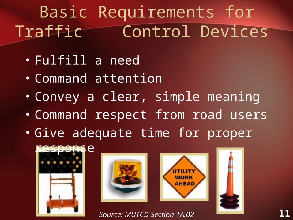
Basic Requirements for Traffic Control Devices
• Fulfill a need
• Command attention
• Convey a clear, simple meaning
• Command respect from road users
• Give adequate time for proper response
Source: MUTCD Section 1A.02

12
Temporary Traffic Control Signs
• Message, layout, and configuration per MUTCD
• Construction fluorescent orange color with mircoprismatic retro-reflective characteristics
• 2 orange supplemental flags may be mounted
• Size = 36” x 36”
• Crashworthy
Source: MUTCD Figure 6F-2

13
Temporary Traffic Control Signs
• Portable temporary traffic control signs
• Reduce work duration and workers’ exposure to risk
• Placing signage lower to the ground may produce a greater impact on the driving population
14
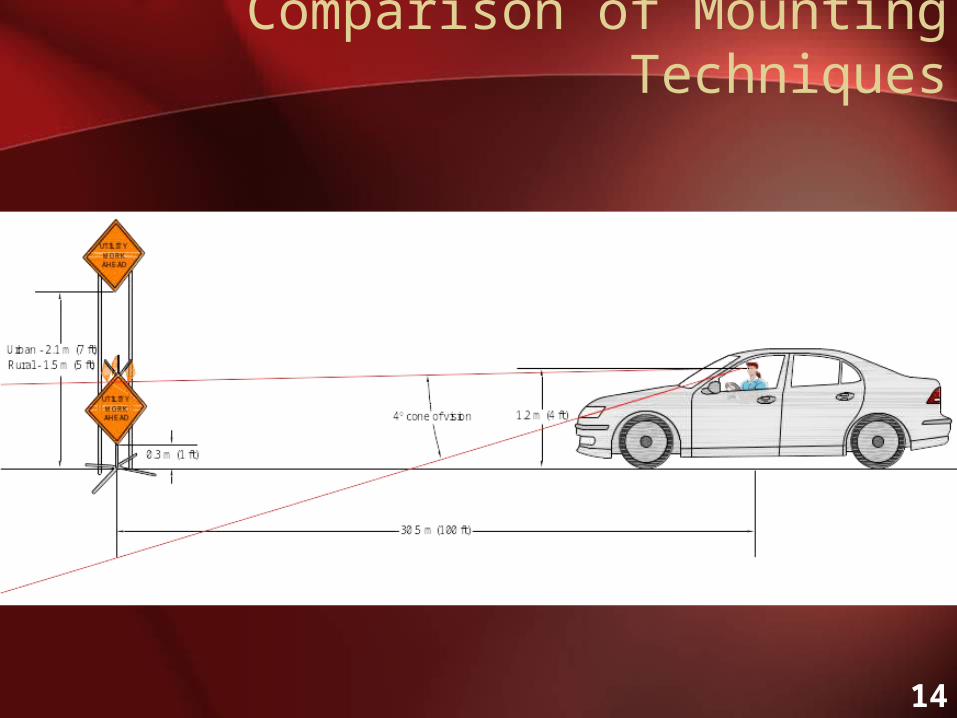
Comparison of Mounting Techniques

15
Comparison of Mounting Techniques
• Drivers tend to look at pavement in front of them
• 4º better than 12º cone of vision• Easier recognition of work zone when signs
are mounted different than typical signs• Retractable stands for parked vehicles
Source: MUTCD Figure 6F-2
16
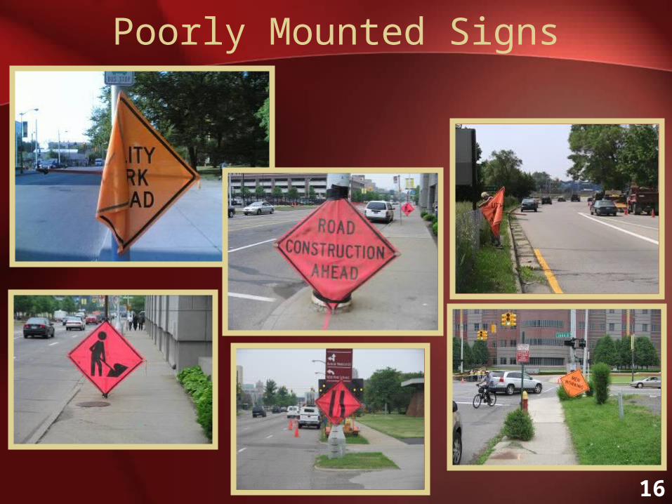
Poorly Mounted Signs

17
Sample Work Zone Warning Signs
For Utility Work Zone Applications
For Other Work Zone Applications

18
Arrow Panels
• Guide motorists to change lanes when work activities are taking place on the road
• Caution motorists of work activities on or adjacent to a shoulder
• To increase visibility and likelihood of drivers responding in a safe and timely manner

19
Arrow Panels
• Support panel 48” H x 96” W
• Minimum of 15 lamps
• Front panel with flat, non-reflective black background
• Mounted at minimum of 7’ from roadway to bottom of panel

20
Arrow Panels
• Flash Rate: 25-40 flashes per minute
• Angularity requirements: For moving operations, work in urban areas use ‘general-purpose (wide) beam’ panels
• Lamp Requirements: Certified by the state; lamp size of PAR 46 or PAR 36

21
Channelizing Devices
• Provides guidance/delineation to motorists • Need to be easily installed and removed• Must be orange and contain retro-reflective bands• Made of a material that will not damage a vehicle if
impacted
• 36” taller cones or tubular markers are more desirable
Source: MUTCD Figure 6F-7

22
Taller Cones
• Use orange taller cones with retro-reflective bands
• Preferred over normal traffic cones
• Provides increased visibility
• Transported easily
• Quick installation and removal on-site

23
Barricades
• Contains 1 to 3 rails of markings
• Used to control road users
• Types I, II, and III

24
Warning Lights on Work Vehicles
• Attract the attention of road users
• Potentially hazardous situation
• Sufficient time for taking appropriate action
• Warning light standardization desirable
• Promote driver understanding
• Recognition of lights on work vehicles

25
Warning Lights on Work Vehicles
• Warning lights should be visible to drivers from all angles (360 degrees)
• Larger vehicles should be equipped with a minimum of three warning lights
• Warning lights should be amber in color

26
• Warning lights should be TURNED ON!
Warning Lights on Work Vehicles

27
Retro-reflective Markings on Work Vehicles
• Visibility increased by the use of retro-reflective
markings and appropriate vehicle colors
• Retro-reflective vehicle markings should
supplement warning light systems
• Retro-reflective material should be affixed to the back of utility work vehicles

28
Retro-reflective Markings on Work Vehicles
• Retro-reflective material should be 4” wide
(8” is desirable)
• Fluorescent orange, white, and black diagonal stripes color pattern

29
Work Vehicles Painted Orange
• Visibility of work vehicle very important
• Orange vehicle is visual cue
• Orange is color for work zones
• Consistency in colors improves safety
• Increases driver awareness and recognition of work zone

30
Work Vehicles Painted Orange
Desirable Vehicle Colors
Undesirable Vehicle Colors

31
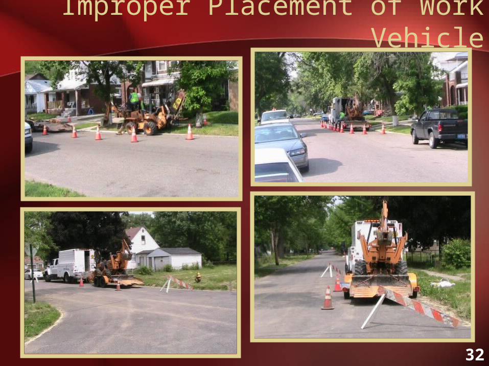
Work Vehicle Placement
• Place vehicle upstream of work area to shield on-foot workers from traffic
• Place upstream to warn vehicles of an upcoming work zone
• Place equipment trailers downstream of work area to avoid being hit by traffic
32
Improper Placement of Work Vehicle

33
Work Vehicle Not Protected
34
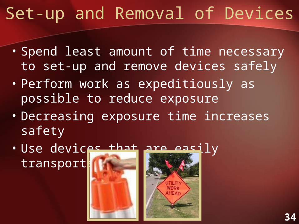
Set-up and Removal of Devices
• Spend least amount of time necessary to set-up and remove devices safely
• Perform work as expeditiously as possible to reduce exposure
• Decreasing exposure time increases safety
• Use devices that are easily transported

35
• Identify traffic control plan ahead of time
• Plan and discuss traffic control off roadway
• Park work vehicles and equipment to maximize safety
• Place traffic control devices as per selected plan starting at beginning of work zone
Set-up of Traffic Control Devices

36
• Remove immediately following completion of work
• Start at end of work zone
• Only leave in place what is needed
• Know where everything goes in work vehicle so no time is wasted
Removal of Traffic Control Devices

37
Worker with proper safety
apparel but not properly protected
from traffic
Worker Safety and Visibility
• Be concerned with personal safety
• Must wear high-visibility safety apparel at all times
• Clothing color orange, yellow, yellow-green, or fluorescent versions of these colors
• Must include retro-reflective materials

38
Worker Safety Apparel
• Proposed Amendment to MUTCD Section 6D.03 requires “American National Standard For High-Visibility Safety Apparel and Headwear”
• ANSI (American National Standards Institute) / ISEA (International Safety Equipment Association) 107-2004
• Class 2 and 3 garments
based on worker activities

39
Other Protective Apparel
• ANSI Compliant Hard Hats
• ANSI Steel Toe Boots
• ANSI Compliant Protective Eyewear

40
Flagger (Traffic Regulator) Training
• For flagger (traffic regulator) training information refer to The National Work
Zone Safety Clearinghouse at http://www.workzonesafety.org/training/

41
Suggested Traffic Control Plans / Pedestrian Issues

42
Utility Work Zone Temporary Traffic Control Components
SHOULDER
SHOULDER
LongitudinalBuffer Space
Lateral Buffer Space
Advanced Warning AreaTransition AreaWork Space
Longitudinal Buffer Space
Downstream Taper
Termination Area Activity Area
Direction of Traffic
Flagger
Flagger
Traffic Space
SHOULDER
SHOULDER
LongitudinalBuffer Space
Lateral Buffer Space
Advanced Warning AreaTransition AreaWork Space
Longitudinal Buffer Space
Downstream Taper
Termination Area Activity Area
Direction of Traffic
Flagger
Flagger
Traffic Space

43
SHOULDER
SHOULDER
LongitudinalBuffer Space
Lateral Buffer Space
Advanced Warning AreaTransition AreaWork Space
Longitudinal Buffer Space
Downstream Taper
Termination Area Activity Area
Direction of Traffic
Flagger
Flagger
Traffic Space
SHOULDER
SHOULDER
LongitudinalBuffer Space
Lateral Buffer Space
Advanced Warning AreaTransition AreaWork Space
Longitudinal Buffer Space
Downstream Taper
Termination Area Activity Area
Direction of Traffic
Flagger
Flagger
Traffic Space
Temporary Traffic Control Components
• Activity Area – work space, traffic space, and
buffer space.• Advanced Warning Area – used to provide warning
to motorists of an upcoming utility activity.
44
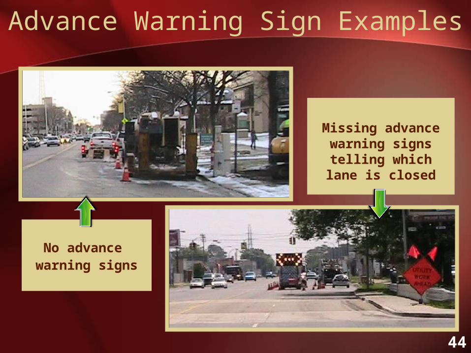
Advance Warning Sign Examples
No advance warning signs
Missing advance warning signs telling which lane is closed
45
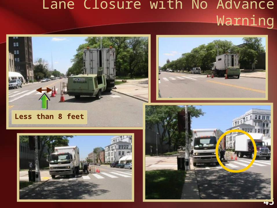
Lane Closure with No Advance Warning
Less than 8 feet

46
Distance Between Traffic Signs
150 m (500 ft)Rural
100 m (350 ft)Urban
>50 km/h (30 mph)
30 m (100 ft)Urban≤ 50 km/h (30 mph)
A (Distance Between Signs)
Road Type
150 m (500 ft)Rural
100 m (350 ft)Urban
>50 km/h (30 mph)
30 m (100 ft)Urban≤ 50 km/h (30 mph)
A (Distance Between Signs)
Road Type
• Note: 30 mph used to differentiate between high and low speeds due to risks involved
47
SHOULDER
SHOULDER
LongitudinalBuffer Space
Lateral Buffer Space
Advanced Warning AreaTransition AreaWork Space
Longitudinal Buffer Space
Downstream Taper
Termination Area Activity Area
Direction of Traffic
Flagger
Flagger
Traffic Space
SHOULDER
SHOULDER
LongitudinalBuffer Space
Lateral Buffer Space
Advanced Warning AreaTransition AreaWork Space
Longitudinal Buffer Space
Downstream Taper
Termination Area Activity Area
Direction of Traffic
Flagger
Flagger
Traffic Space
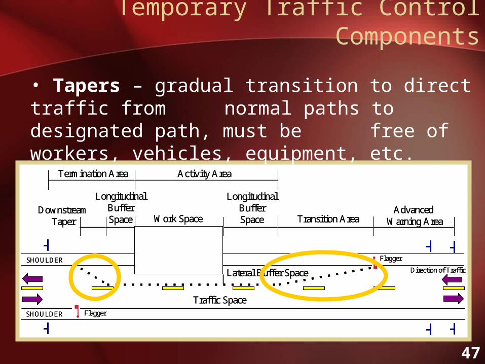
• Tapers – gradual transition to direct traffic from normal paths to designated path, must be free of workers, vehicles, equipment, etc.
Temporary Traffic Control Components

48
Different Types of Tapers
Source: MUTCD Figure 6C-2 and Table 6C-3

49
Formulas for Calculating Taper Lengths
Source: MUTCD Table 6C-4

50
• Buffer Space (Optional) – lateral and/or longitudinal area that separates traffic from work space, must be free of workers, vehicles, equipment, etc.
Temporary Traffic Control Components
SHOULDER
SHOULDER
LongitudinalBuffer Space
Lateral Buffer Space
Advanced Warning AreaTransition AreaWork Space
Longitudinal Buffer Space
Downstream Taper
Termination Area Activity Area
Direction of Traffic
Flagger
Flagger
Traffic Space
SHOULDER
SHOULDER
LongitudinalBuffer Space
Lateral Buffer Space
Advanced Warning AreaTransition AreaWork Space
Longitudinal Buffer Space
Downstream Taper
Termination Area Activity Area
Direction of Traffic
Flagger
Flagger
Traffic Space

51
Why Use a Buffer Space?
• Easy to accommodate into plan
• Inexpensive
• Improves worker safety
• Provides additional space between work zone and motorists

52
Buffer Space Issues
Did not usebuffer space
Used buffer space but no taper

53
Buffer Space Issues
No room for buffer space

54
SHOULDER
SHOULDER
LongitudinalBuffer Space
Lateral Buffer Space
Advanced Warning AreaTransition AreaWork Space
Longitudinal Buffer Space
Downstream Taper
Termination Area Activity Area
Direction of Traffic
Flagger
Flagger
Traffic Space
SHOULDER
SHOULDER
LongitudinalBuffer Space
Lateral Buffer Space
Advanced Warning AreaTransition AreaWork Space
Longitudinal Buffer Space
Downstream Taper
Termination Area Activity Area
Direction of Traffic
Flagger
Flagger
Traffic Space
• Termination Area – area used to return to normal path
• Traffic Space – portion of highway in which road users are routed through the activity area
Temporary Traffic Control Components

55
• Transition Area – area utilized to move motorists
from their normal path
• Work Space – portion closed to road users – occupied by utility workers, equipment and vehicles.
SHOULDER
SHOULDER
LongitudinalBuffer Space
Lateral Buffer Space
Advanced Warning AreaTransition AreaWork Space
Longitudinal Buffer Space
Downstream Taper
Termination Area Activity Area
Direction of Traffic
Flagger
Flagger
Traffic Space
SHOULDER
SHOULDER
LongitudinalBuffer Space
Lateral Buffer Space
Advanced Warning AreaTransition AreaWork Space
Longitudinal Buffer Space
Downstream Taper
Termination Area Activity Area
Direction of Traffic
Flagger
Flagger
Traffic Space
SHOULDER
SHOULDER
LongitudinalBuffer Space
Lateral Buffer Space
Advanced Warning AreaTransition AreaWork Space
Longitudinal Buffer Space
Downstream Taper
Termination Area Activity Area
Direction of Traffic
Flagger
Flagger
Traffic Space
SHOULDER
SHOULDER
LongitudinalBuffer Space
Lateral Buffer Space
Advanced Warning AreaTransition AreaWork Space
Longitudinal Buffer Space
Downstream Taper
Termination Area Activity Area
Direction of Traffic
Flagger
Flagger
Traffic Space
Temporary Traffic Control Components

56
Utility Work Beyond Shoulder
SHOULDER
WORK SITE
SHOULDER
WORK VEHICLE
*
> 4.6 m (15 ft) from edge of roadway or > 0.6m (2 ft) behind curb where curb and gutter present
* Oscillating warning lights or strobe lights operatingEdge of Roadway
Direction of Traffic
SHOULDER
WORK SITE
SHOULDER
WORK VEHICLE
*
> 4.6 m (15 ft) from edge of roadway or > 0.6m (2 ft) behind curb where curb and gutter present
* Oscillating warning lights or strobe lights operatingEdge of Roadway
Direction of Traffic
**

57
Utility Work Beyond Shoulder with Work Vehicle(s) Parked on Shoulder
SHOULDER
WORK SITE
SHOULDER
*
WORK VEHICLE
> 4.6 m (15 ft) from edge of roadway or > 0.6m (2 ft) behind curb where curb and gutter present
* Oscillating warning lights or strobe lights operatingEdge of Roadway
Direction of Traffic
SHOULDER
WORK SITE
SHOULDER
*
WORK VEHICLE
> 4.6 m (15 ft) from edge of roadway or > 0.6m (2 ft) behind curb where curb and gutter present
* Oscillating warning lights or strobe lights operatingEdge of Roadway
Direction of Traffic**

58
Utility Work on Shoulder (Low Traffic Volume and Low Speed)
SHOULDER
WORK SITE
SHOULDER
WORK VEHICLE
*
* Oscillating warning lights or strobe lights operatingEdge of Roadway
Direction of Traffic
SHOULDER
WORK SITE
SHOULDER
* Oscillating warning lights or strobe lights operatingEdge of Roadway
Direction of Traffic
150 m (500 ft)Rural
100 m (350 ft)Urban
>50 km/h (30 mph)
30 m (100 ft)Urban≤ 50 km/h (30 mph)
A (Distance Between Signs)
Road Type
***

59
Utility Work Beyond Shoulder with Work Vehicle Parked on Shoulder
(High Traffic Volume and/or High Speed)
SHOULDER
3 m (10 ft) minimum
*
WORK VEHICLE
Urban-30 m (100 ft)Rural-150 m (500 ft)
WORK SITE
* Oscillating warning lights or strobe lights operatingEdge of Roadway
Buffer(optional)
Downstream Taper
(nominal)
Urban-30 m (100 ft)Rural-150 m (500 ft)
Lateral Buffer (optional)
Taller Cone (Typ.)
Direction of Traffic
SHOULDER
3 m (10 ft) minimum
*
WORK VEHICLE
Urban-30 m (100 ft)Rural-150 m (500 ft)
WORK SITE
* Oscillating warning lights or strobe lights operatingEdge of Roadway
Buffer(optional)
Downstream Taper
(nominal)
Urban-30 m (100 ft)Rural-150 m (500 ft)
Taller Cone (Typ.)
Direction of Traffic
**
30 m (100 ft) L/3

60
Utility Work Beyond Shoulder with Work Vehicle(s) Parked on Shoulder (High Traffic Volume and/or High Speed)
SHOULDER
POSSIBLE WORK SITE WORK
VEHICLE
*
100 m (350 ft)
* Oscillating warning lights or strobe lights operatingEdge of Roadway
SHOULDER
Buffer(optional)
Lateral Buffer (optional)
Downstream Taper
(nominal)
Taller Cone (Typ.)
Direction of Traffic
SHOULDER
POSSIBLE WORK SITE WORK
VEHICLE
*
100 m
* Oscillating warning lights or strobe lights operatingEdge of Roadway
SHOULDER
Buffer(optional)(nominal)
Taller Cone (Typ.)
Direction of Traffic
**
30 m (100 ft) L/3

61
Utility Work on Shoulder with no Encroachment on Roadway
(High Traffic Volume and High Speed)
SHOULDER
3 m (10 ft) minimum
*
WORK VEHICLE
Urban-100 m (350 ft)Rural-150 m (500 ft)
WORK SITE
* Oscillating warning lights or strobe lights operatingEdge of Roadway
Buffer(optional)
Downstream Taper
(nominal)
Urban-30 m (100 ft)Rural-150 m (500 ft)
Lateral Buffer (optional)
Taller Cone (Typ.)
Direction of Traffic
SHOULDER *
WORK VEHICLE
Urban-Rural-
WORK SITE
* Oscillating warning lights or strobe lights operatingEdge of Roadway
Buffer(optional)
Downstream Taper 30 m (100 ft)
(nominal)
Urban-Rural-
Taller Cone (Typ.)
Direction of Traffic
**
L/3

62
Utility Work on Shoulder with No Encroachment on Roadway
(High Traffic Volume and/or High Speed)
SHOULDER
WORK VEHICLE
*
100 m (350 ft)
* Oscillating warning lights or strobe lights operatingEdge of Roadway
SHOULDER
Buffer(optional)
Lateral Buffer (optional)
Downstream Taper 30 m (100 ft) (nominal)
Taller Cone (Typ.)
Direction of Traffic
SHOULDER
POSSIBLE
WORK SITE
WORK VEHICLE
*
100 m
* Oscillating warning lights or strobe lights operatingEdge of Roadway
SHOULDER
Buffer(optional)(nominal)
Taller Cone (Typ.)
Direction of Traffic
**
L/3

63
Utility Work on Shoulder with Minor Encroachment(High Traffic Volume and High Speed)
SHOULDER
3 m (10 ft) minimum
*
WORK VEHICLE
Urban-100 m (350 ft)Rural-150 m (500 ft)
WORK SITE
* Oscillating warning lights or strobe lights operatingEdge of Roadway
Buffer(optional)
Downstream Taper 30 m (100 ft) (nominal)
Urban-30 m (100 ft)Rural-150 m (500 ft)
Lateral Buffer (optional)
Taller Cone (Typ.)
Direction of Traffic
SHOULDER
3 m (10 ft) minimum
*
WORK VEHICLE
Urban-Rural-
WORK SITE
* Oscillating warning lights or strobe lights operatingEdge of Roadway
Buffer(optional)
Downstream Taper
(nominal)
Urban-Rural-
Taller Cone (Typ.)
Direction of Traffic
**
L/3
64
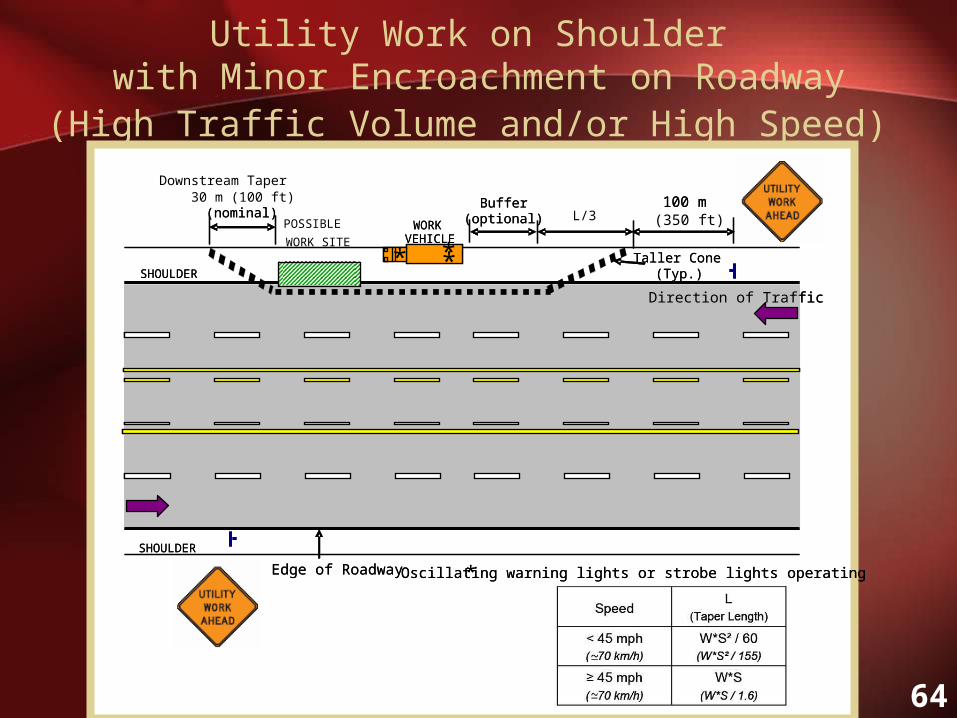
Utility Work on Shoulder with Minor Encroachment on Roadway
(High Traffic Volume and/or High Speed)
SHOULDER
WORK VEHICLE
*
100 m (350 ft)
* Oscillating warning lights or strobe lights operatingEdge of Roadway
SHOULDER
Buffer(optional)
Lateral Buffer (optional)
Downstream Taper 30 m (100 ft) (nominal)
Taller Cone (Typ.)
Direction of Traffic
SHOULDER
POSSIBLE
WORK SITE
WORK VEHICLE
*
100 m
* Oscillating warning lights or strobe lights operatingEdge of Roadway
SHOULDER
Buffer(optional)(nominal)
Taller Cone (Typ.)
Direction of Traffic
**
L/3

65
Utility Work on Shoulder with Minor Encroachment(Low Traffic Volume and Low Speed)
SHOULDER
3 m (10 ft) minimum
*
WORK VEHICLE
Urban-30 m (100 ft)Rural-150 m (500 ft)
WORK SITE
* Oscillating warning lights or strobe lights operatingEdge of Roadway
Buffer(optional)
Downstream Taper 30 m (100 ft) (nominal)
Urban-30 m (100 ft)Rural-150 m (500 ft)
Lateral Buffer (optional)
Taller Cone (Typ.)
Direction of Traffic
SHOULDER
3 m (10 ft) minimum
*
WORK VEHICLE
Urban-Rural-
WORK SITE
* Oscillating warning lights or strobe lights operatingEdge of Roadway
Buffer(optional)
Downstream Taper
(nominal)
Urban-Rural-
Taller Cone (Typ.)
Direction of Traffic
**
L/3

66
Utility Work on Shoulder with Minor Encroachment or Lane Closure on Two-Lane Road
(High Traffic Volume and/or High Speed)
SHOULDER
30 m (100 ft)
max.
*
AHEAD
WORK SITEWORK
VEHICLE
Note: Work activity shown depicts shoulder work with minor encroachment
Downstream Taper 30 m (100 ft)
* Oscillating warning lights or strobe lights operatingEdge of Roadway
Urban: 100 m (350 ft) Rural: 150 m (500 ft)
Buffer(optional)
Lateral Buffer (optional)
Flagger
Flagger
Urban: 100 m (350 ft) Rural: 150 m (500 ft)
Urban: 100 m (350 ft) Rural: 150 m (500 ft)
Urban: 100 m (350 ft) Rural: 150 m (500 ft)
Urban: 100 m (350 ft) Rural: 150 m (500 ft)
Urban: 100 m (350 ft) Rural: 150 m (500 ft)
Taller Cone (Typ.)Direction of Traffic
AHEAD
* *

67
Temporary Road Closure
WORK SITE
WORK VEHICLES
150 m (500 ft)Rural
100 m (350 ft)Urban
>50 km/h (30 mph)
30 m (100 ft)Urban= 50 km/h (30 mph)
A (Distance Between Signs)
Road Type
A
Dir
ecti
on o
f T
raff
ic
*
*
* Oscillating warning lights or strobe lights operating
Type III Barricade (Typ.)
A
AHEAD
AHEAD
SHOULDER
SHOULDER
Police Vehicle with Flashers On
(Optional)
Police Officer in uniform
regulating traffic
Police Vehicle with Flashers On
(Optional)
Police Officer in uniform
regulating traffic
(Temporary Portable Sign, No
Left Turn)
(Temporary Portable Sign, No
Left Turn)
(Temporary Portable Sign, No Right Turn)
(Temporary Portable Sign, No Right Turn)
WORK SITE
WORK VEHICLES
150 m (500 ft)Rural
100 m (350 ft)Urban
>50 km/h (30 mph)
30 m (100 ft)Urban= 50 km/h (30 mph)
A (Distance Between Signs)
Road Type
150 m (500 ft)Rural
100 m (350 ft)Urban
>50 km/h (30 mph)
30 m (100 ft)Urban= 50 km/h (30 mph)
A (Distance Between Signs)
Road Type
A
Dir
ecti
on o
f T
raff
ic
*
*
* Oscillating warning lights or strobe lights operating
Type III Barricade (Typ.)
A
AHEADAHEAD
AHEADAHEAD
SHOULDER
SHOULDER
Police Vehicle with Flashers On
(Optional)
Police Officer in uniform
regulating traffic
Police Vehicle with Flashers On
(Optional)
Police Officer in uniform
regulating traffic
(Temporary Portable Sign, No
Left Turn)
(Temporary Portable Sign, No
Left Turn)
(Temporary Portable Sign, No Right Turn)
(Temporary Portable Sign, No Right Turn)
**
**

68
Right Lane Closure on
Near Side of Intersection
* (Optional)
*Oscillating warning lights or strobe lights operating
Edge of Roadway
150 m (500 ft)Rural
100 m (350 ft)Urban
>50 km/h (30 mph)
30 m (100 ft)Urban= 50 km/h (30 mph)
A (Distance Between Signs)
Road Type
L
A
A
Buffer(optional)
A
Lateral Buffer (optional)
>50 km/h (30 mph) 290 m (950 ft)2
90 m (300 ft)1
100 m (350 ft)2
30 m (100 ft)1= 50 km/h (30 mph)
L (Taper Length)
Number of Lanes Closed*Speed
*Assume 12’ lanes
Taller Cone (Typ.)
Direction of Traffic
AHEAD
* (Optional)
*Oscillating warning lights or strobe lights operating
Edge of Roadway
150 m (500 ft)Rural
100 m (350 ft)Urban
>50 km/h (30 mph)
30 m (100 ft)Urban= 50 km/h (30 mph)
A (Distance Between Signs)
Road Type
150 m (500 ft)Rural
100 m (350 ft)Urban
>50 km/h (30 mph)
30 m (100 ft)Urban= 50 km/h (30 mph)
A (Distance Between Signs)
Road Type
L
A
A
Buffer(optional)
A
Lateral Buffer (optional)
>50 km/h (30 mph) 290 m (950 ft)2
90 m (300 ft)1
100 m (350 ft)2
30 m (100 ft)1= 50 km/h (30 mph)
L (Taper Length)
Number of Lanes Closed*Speed
*Assume 12’ lanes
>50 km/h (30 mph) 290 m (950 ft)2
90 m (300 ft)1
100 m (350 ft)2
30 m (100 ft)1= 50 km/h (30 mph)
L (Taper Length)
Number of Lanes Closed*Speed
*Assume 12’ lanes
Taller Cone (Typ.)
Direction of Traffic
AHEADAHEAD
**

69
Left Lane Closure on
Near Side of Intersection
L
A
A
* (Optional)
* Oscillating warning lights or strobe lights operating
Edge of Roadway
150 m (500 ft)Rural
100 m (350 ft)Urban
>50 km/h (30 mph)
30 m (100 ft)Urban= 50 km/h (30 mph)
A (Distance Between Signs)
Road TypeBuffer
(optional)
Lateral Buffer (optional)
A
>50 km/h (30 mph) 290 m (950 ft)2
90 m (300 ft)1
100 m (350 ft)2
30 m (100 ft)1= 50 km/h (30 mph)
L (Taper Length)
Number of Lanes Closed*Speed
*Assume 12’ lanes
TallerCone (Typ.)
Direction of Traffic
LEFT
L
A
A
* (Optional)
* Oscillating warning lights or strobe lights operating
Edge of Roadway
150 m (500 ft)Rural
100 m (350 ft)Urban
>50 km/h (30 mph)
30 m (100 ft)Urban= 50 km/h (30 mph)
A (Distance Between Signs)
Road Type
150 m (500 ft)Rural
100 m (350 ft)Urban
>50 km/h (30 mph)
30 m (100 ft)Urban= 50 km/h (30 mph)
A (Distance Between Signs)
Road TypeBuffer
(optional)
Lateral Buffer (optional)
A
>50 km/h (30 mph) 290 m (950 ft)2
90 m (300 ft)1
100 m (350 ft)2
30 m (100 ft)1= 50 km/h (30 mph)
L (Taper Length)
Number of Lanes Closed*Speed
*Assume 12’ lanes
>50 km/h (30 mph) 290 m (950 ft)2
90 m (300 ft)1
100 m (350 ft)2
30 m (100 ft)1= 50 km/h (30 mph)
L (Taper Length)
Number of Lanes Closed*Speed
*Assume 12’ lanes
TallerCone (Typ.)
Direction of Traffic
LEFTLEFT
**

70
Right Lane Closure on Far Side of Intersection
A
A
A
A
* (Optional)
(Optional)
A
L
WORK VEHICLE
WORK SITE
* Oscillating warning lights or strobe lights operating
Edge of Roadway
150 m (500 ft)Rural
100 m (350 ft)Urban
>50 km/h (30 mph)
30 m (100 ft)Urban= 50 km/h (30 mph)
A (Distance Between Signs)
Road Type
Lateral Buffer
(optional)
>50 km/h (30 mph) 290 m (950 ft)2
90 m (300 ft)1
100 m (350 ft)2
30 m (100 ft)1= 50 km/h (30 mph)
L (Taper Length)
Number of Lanes Closed*Speed
*Assume 12’ lanes
Taller Cone (Typ.)
30 m (100 ft)(optional)
Direction of Traffic
Buffer(optional)
AHEAD
A
A
A
A
* (Optional)
(Optional)
A
L
WORK VEHICLE
WORK SITE
* Oscillating warning lights or strobe lights operating
Edge of Roadway
150 m (500 ft)Rural
100 m (350 ft)Urban
>50 km/h (30 mph)
30 m (100 ft)Urban= 50 km/h (30 mph)
A (Distance Between Signs)
Road Type
150 m (500 ft)Rural
100 m (350 ft)Urban
>50 km/h (30 mph)
30 m (100 ft)Urban= 50 km/h (30 mph)
A (Distance Between Signs)
Road Type
Lateral Buffer
(optional)
>50 km/h (30 mph) 290 m (950 ft)2
90 m (300 ft)1
100 m (350 ft)2
30 m (100 ft)1= 50 km/h (30 mph)
L (Taper Length)
Number of Lanes Closed*Speed
*Assume 12’ lanes
>50 km/h (30 mph) 290 m (950 ft)2
90 m (300 ft)1
100 m (350 ft)2
30 m (100 ft)1= 50 km/h (30 mph)
L (Taper Length)
Number of Lanes Closed*Speed
*Assume 12’ lanes
Taller Cone (Typ.)
30 m (100 ft)(optional)
Direction of Traffic
Buffer(optional)
AHEADAHEAD
**
71
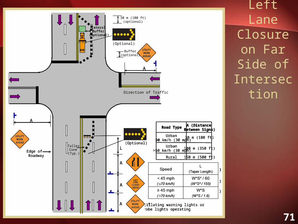
Left Lane Closure on Far Side of Intersection
*
(Optional)
150 m (500 ft)Rural
100 m (350 ft)Urban
>50 km/h (30 mph)
30 m (100 ft)Urban= 50 km/h (30 mph)
A (Distance Between Signs)
Road Type
* Oscillating warning lights or strobe lights operating
(Optional)
L
A
A
A
Edge of Roadway
A
A
Lateral Buffer
(optional)
>50 km/h (30 mph) 290 m (950 ft)2
90 m (300 ft)1
100 m (350 ft)2
30 m (100 ft)1
A (Distance Between Signs)
Road Type
150 m (500 ft)Rural
100 m (350 ft)Urban
>50 km/h (30 mph)
30 m (100 ft)Urban= 50 km/h (30 mph)
A (Distance Between Signs)
Road Type
* Oscillating warning lights or strobe lights operating
(Optional)
L
A
A
A
Edge of Roadway
A
A
Lateral Buffer
(optional)
>50 km/h (30 mph) 290 m (950 ft)2
90 m (300 ft)1
100 m (350 ft)2
30 m (100 ft)1= 50 km/h (30 mph)
L (Taper Length)
Number of Lanes Closed*Speed
*Assume 12’ lanes
>50 km/h (30 mph) 290 m (950 ft)2
90 m (300 ft)1
100 m (350 ft)2
30 m (100 ft)1= 50 km/h (30 mph)
L (Taper Length)
Number of Lanes Closed*Speed
*Assume 12’ lanes
TallerCone (Typ.)
30 m (100 ft)(optional)
Direction of Traffic
Buffer(optional)
LEFTLEFT
**

72
Closure in Center of
Intersection
Urban-30 m (100 ft)Rural-150 m (500 ft)
L/210’min
L/2 10’min
L/2
10’min
L/2
10’min
*
WORK VEHICLE WORK
SITE
Edge of Roadway
45 m (150 ft)>50 km/h (30 mph)
15 m (50 ft)= 50 km/h (30 mph)
L/2 (Taper
Length)Speed Limit
Urban-30 m (100 ft)Rural-150 m (500 ft)
Urban-30 m (100 ft)Rural-150 m (500 ft)
Urban-30 m (100 ft)Rural-150 m (500 ft)
* Oscillating warning lights or strobe lights operating
Taller Cone (Typ.)
Direction of Traffic
Urban-30 m (100 ft)Rural-150 m (500 ft)
L/210’min
L/2 10’min
L/2
10’min
L/2
10’min
*
WORK VEHICLE WORK
SITE
Edge of Roadway
45 m (150 ft)>50 km/h (30 mph)
15 m (50 ft)= 50 km/h (30 mph)
L/2 (Taper
Length)Speed Limit
Urban-30 m (100 ft)Rural-150 m (500 ft)
Urban-30 m (100 ft)Rural-150 m (500 ft)
Urban-30 m (100 ft)Rural-150 m (500 ft)
* Oscillating warning lights or strobe lights operating
Taller Cone (Typ.)
Direction of Traffic*
*

73
Center Lane
Closure on a
Multi-Lane Road
A
A
(Optional)
L
*
A
A
L
(Optional)
* Oscillating warning lights or strobe lights operating
Edge of Roadway
Lateral Buffer
(optional)
30 m (100 ft)(optional)
30 m (100 ft)(optional)
Buffer(optional)
Buffer(optional)
150 m (500 ft)Rural
100 m (350 ft)Urban>50 km/h (30 mph)
30 m (100 ft)Urban= 50 km/h (30 mph)
A (Distance Between Signs)
Road Type
>50 km/h (30 mph) 290 m (950 ft)2
90 m (300 ft)1
100 m (350 ft)2
30 m (100 ft)1= 50 km/h (30 mph)
L (Taper Length)
Number of Lanes Closed*Speed
*Assume 12’ lanes
Taller Cone (Typ.)
Dir
ecti
on o
f T
raff
ic
*
A
A
(Optional)
*
A
A
L
(Optional)
* Oscillating warning lights or strobe lights operating
Edge of Roadway
Lateral Buffer
(optional)
30 m (100 ft)(optional)
30 m (100 ft)(optional)
Buffer(optional)
Buffer(optional)
150 m (500 ft)Rural
100 m (350 ft)Urban>50 km/h (30 mph)
30 m (100 ft)Urban= 50 km/h (30 mph)
A (Distance Between Signs)
Road Type
150 m (500 ft)Rural
100 m (350 ft)Urban>50 km/h (30 mph)
30 m (100 ft)Urban= 50 km/h (30 mph)
A (Distance Between Signs)
Road Type
>50 km/h (30 mph) 290 m (950 ft)2
90 m (300 ft)1
100 m (350 ft)2
30 m (100 ft)1= 50 km/h (30 mph)
L (Taper Length)
Number of Lanes Closed*Speed
*Assume 12’ lanes
>50 km/h (30 mph) 290 m (950 ft)2
90 m (300 ft)1
100 m (350 ft)2
30 m (100 ft)1= 50 km/h (30 mph)
L (Taper Length)
Number of Lanes Closed*Speed
*Assume 12’ lanes
Taller Cone (Typ.)
Dir
ecti
on o
f T
raff
ic
* **
**

74
Lane Closure On Two-Lane Road
(Restricted Visibility)
WORK VEHICLE
WORK SITE
A
A
A
AHEAD
*
A
AHEAD
A
A
* Oscillating warning lights or strobe lights operating
Edge of Roadway
Lateral Buffer
(optional)
150 m (500 ft)Rural
100 m (350 ft)Urban
>50 km/h (30 mph)
30 m (100 ft)Urban= 50 km/h (30 mph)
A (Distance Between Signs)
Road Type
30 m (100 ft)
max.
Taller Cone (Typ.)
Downstream Taper30 m (100 ft)
(Max)
Dir
ecti
on o
f T
raff
ic
WORK VEHICLE
WORK SITE
A
A
A
AHEAD
*
A
AHEAD
A
A
* Oscillating warning lights or strobe lights operating
Edge of Roadway
Lateral Buffer
(optional)
150 m (500 ft)Rural
100 m (350 ft)Urban
>50 km/h (30 mph)
30 m (100 ft)Urban= 50 km/h (30 mph)
A (Distance Between Signs)
Road Type
150 m (500 ft)Rural
100 m (350 ft)Urban
>50 km/h (30 mph)
30 m (100 ft)Urban= 50 km/h (30 mph)
A (Distance Between Signs)
Road Type
30 m (100 ft)
max.
Taller Cone (Typ.)
Downstream Taper30 m (100 ft)
(Max)
Dir
ecti
on o
f T
raff
ic
*
*
75
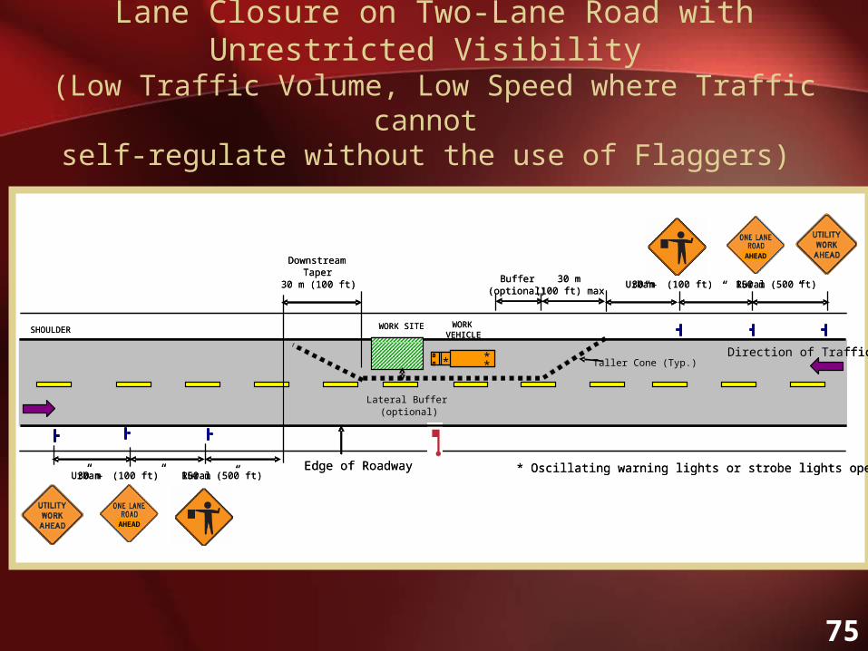
Lane Closure on Two-Lane Road with Unrestricted Visibility (Low Traffic Volume, Low Speed where Traffic cannot
self-regulate without the use of Flaggers)
SHOULDER
*
AHEAD
”
“
AHEAD
““
WORK VEHICLE
WORK SITE
30 m (100 ft) max
Downstream Taper
30 m (100 ft)
* Oscillating warning lights or strobe lights operatingEdge of Roadway
Buffer(optional)
Urban-30 m (100 ft) Rural -150 m (500 ft)
””
Urban-30 m (100 ft) Rural -150 m (500 ft)
Lateral Buffer (optional)
Taller Cone (Typ.)Direction of Traffic
SHOULDER
AHEAD
”
“
AHEAD
““
WORK VEHICLE
WORK SITE
30 m (100 ft) max
Downstream Taper
30 m (100 ft)
* Oscillating warning lights or strobe lights operatingEdge of Roadway
Buffer(optional)
Urban-30 m (100 ft) Rural -150 m (500 ft)
””
Urban-30 m (100 ft) Rural -150 m (500 ft)
Lateral Buffer (optional)
Taller Cone (Typ.)Direction of Traffic
***

76
Lane Closure on Two-Lane Road with Unrestricted Visibility (Low Traffic Volume, Low Speed where Traffic can
self-regulate without the use of Flaggers)
SHOULDER
*
WORK VEHICLE
WORK SITE
30 m (100 ft) max
Downstream Taper
30 m (100 ft)
* Oscillating warning lights or strobe lights operatingEdge of Roadway
Buffer(optional)
Urban-30 m (100 ft) Rural-150 m (500 ft)
Urban-30 m (100 ft) Rural-150 m (500 ft)
Lateral Buffer (optional)
Taller Cone (Typ.)Direction of Traffic
SHOULDERWORK
VEHICLEWORK SITE
30 m (100 ft) max
Downstream Taper
30 m (100 ft)
* Oscillating warning lights or strobe lights operatingEdge of Roadway
Buffer(optional)
Urban-30 m (100 ft) Rural-150 m (500 ft)
Urban-30 m (100 ft) Rural-150 m (500 ft)
Lateral Buffer (optional)
Taller Cone (Typ.)Direction of Traffic
** *

77
Utility Work in Center of Road (Low Traffic Volumes)
SHOULDER
L/2
WORK SITE 3 m (10 ft) MIN
L/2
*WORK
VEHICLE
* Oscillating warning lights or strobe lights operatingEdge of Roadway
SHOULDER
Urban-30 m (100 ft)Rural-150 m (500 ft)
Urban-30 m (100 ft)Rural-150 m (500 ft)
45 m (150 ft)>50 km/h (30 mph)
15 m (50 ft)= 50 km/h (30 mph)
L/2 (Taper Length)
Speed Limit
Taller Cone (Typ.)
Direction of Traffic
3 m (10 ft) MIN
SHOULDER
L/2
WORK SITE 3 m (10 ft) MIN
L/2
*WORK
VEHICLE
* Oscillating warning lights or strobe lights operatingEdge of Roadway
SHOULDER
Urban-30 m (100 ft)Rural-150 m (500 ft)
Urban-30 m (100 ft)Rural-150 m (500 ft)
45 m (150 ft)>50 km/h (30 mph)
15 m (50 ft)= 50 km/h (30 mph)
L/2 (Taper Length)
Speed Limit
45 m (150 ft)>50 km/h (30 mph)
15 m (50 ft)= 50 km/h (30 mph)
L/2 (Taper Length)
Speed Limit
Taller Cone (Typ.)
Direction of Traffic
3 m (10 ft) MIN
**

78
Outside Lane Closure on Multi-Lane Road
SHOULDERWORK VEHICLE
AL
* Oscillating warning lights or strobe lights operatingEdge of Roadway
SHOULDER
Buffer(optional)
Lateral Buffer (optional)
Taller Cone (Typ.)
Direction of Traffic
Downstream Taper
30 m (100 ft)A A
150 m (500 ft)Rural
100 m (350 ft)Urban
>50 km/h (30 mph)
30 m (100 ft)Urban= 50 km/h (30 mph)
A (Distance Between Signs)
Road Type
*
>50 km/h (30 mph) 290 m (950 ft)2
90 m (300 ft)1
100 m (350 ft)2
30 m (100 ft)1= 50 km/h (30 mph)
L (Taper Length)
Number of Lanes Closed*Speed
*Assume 12’ lanes
WORK SITE
AHEAD
SHOULDERWORK VEHICLE
AL
* Oscillating warning lights or strobe lights operatingEdge of Roadway
SHOULDER
Buffer(optional)
Lateral Buffer (optional)
Taller Cone (Typ.)
Direction of Traffic
Downstream Taper
30 m (100 ft)A A
150 m (500 ft)Rural
100 m (350 ft)Urban
>50 km/h (30 mph)
30 m (100 ft)Urban= 50 km/h (30 mph)
A (Distance Between Signs)
Road Type
150 m (500 ft)Rural
100 m (350 ft)Urban
>50 km/h (30 mph)
30 m (100 ft)Urban= 50 km/h (30 mph)
A (Distance Between Signs)
Road Type
*
>50 km/h (30 mph) 290 m (950 ft)2
90 m (300 ft)1
100 m (350 ft)2
30 m (100 ft)1= 50 km/h (30 mph)
L (Taper Length)
Number of Lanes Closed*Speed
*Assume 12’ lanes
>50 km/h (30 mph) 290 m (950 ft)2
90 m (300 ft)1
100 m (350 ft)2
30 m (100 ft)1= 50 km/h (30 mph)
L (Taper Length)
Number of Lanes Closed*Speed
*Assume 12’ lanes
WORK SITE
AHEADAHEAD
**
79
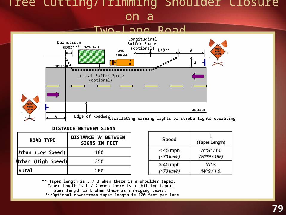
Tree Cutting/Trimming Shoulder Closure on a Two-Lane Road
SHOULDER
SHOULDER
*
A
WORK SITE
WORK VEHICLE
A
W
LongitudinalBuffer Space
(optional)
Downstream Taper***
L/3**
Lateral Buffer Space (optional)
500Rural
350Urban (High Speed)
100Urban (Low Speed)
DISTANCE ‘A’ BETWEEN SIGNS IN FEET
ROAD TYPE
DISTANCE BETWEEN SIGNS
** Taper length is L / 3 when there is a shoulder taper. Taper length is L / 2 when there is a shifting taper.Taper length is L when there is a merging taper.
***Optional downstream taper length is 100 feet per lane
* Oscillating warning lights or strobe lights operatingEdge of Roadway
SHOULDER
SHOULDER
*
A
WORK SITE
WORK VEHICLE
A
W
LongitudinalBuffer Space
(optional)
Downstream Taper***
L/3**
Lateral Buffer Space (optional)
500Rural
350Urban (High Speed)
100Urban (Low Speed)
DISTANCE ‘A’ BETWEEN SIGNS IN FEET
ROAD TYPE
DISTANCE BETWEEN SIGNS
** Taper length is L / 3 when there is a shoulder taper. Taper length is L / 2 when there is a shifting taper.Taper length is L when there is a merging taper.
***Optional downstream taper length is 100 feet per lane
* Oscillating warning lights or strobe lights operatingEdge of Roadway
**

80
Tree Cutting/Trimming Lane Closure on a Multi-Lane Road
A
*
A
W
LongitudinalBuffer Space
(optional)Downstream
Taper*** L**
Lateral Buffer Space (optional)
A
500Rural
350Urban (High Speed)
100Urban (Low Speed)
DISTANCE ‘A’ BETWEEN SIGNS IN FEET
ROAD TYPE
DISTANCE BETWEEN SIGNS
* Oscillating warning lights or strobe lights operating
** Taper length is L / 3 when there is a shoulder taper. Taper length is L / 2 when there is a shifting taper.Taper length is L when there is a merging taper.
***Optional downstream taper length is 100 feet per lane
Edge of Roadway
* *

81
Pedestrian Issues
• Must identify pedestrian needs
• Should not be forced to enter into work zone
• Should not be forced to enter into roadway
• Pedestrian paths must be maintained

82
“When existing pedestrian facilities are disrupted, closed, or relocated in a TTC zone,
the temporary facilities shall be detectable
and include accessibility features
consistent with the features present
in the existing pedestrian facility.”
Considering Pedestrians
Source: MUTCD Section 6D.02

83
Examples of Improper Pedestrian Traffic Control

84
Examples of Improper Pedestrian Traffic Control

85
Pedestrian Traffic Control Plans
• Pedestrian Detour for Sidewalk Closure• Pedestrian Diversion for Sidewalk Closure• Must be ADA Compliant

86
Sidewalk Detour for Pedestrians U
Dir
ecti
on o
f T
raff
ic
Type III Barricade (Typ.)
OptionalWORK SITE
Dir
ecti
on o
f T
raff
ic
Type III Barricade (Typ.)
OptionalWORK SITE

87
Sidewalk Diversion for Pedestrians V
Dir
ectio
n of
T
raff
ic
900 mm (36 in) MIN
Type III Barricade (Typ.)
WORK SITEDir
ectio
n of
T
raff
ic
900 mm (36 in) MIN
Type III Barricade (Typ.)
WORK SITE

88
15-Minute Break

89
How do You Select a Proper Traffic Control Plan?

90
Traffic Control Plan Selection
• Location of utility work
• Traffic volume of adjacent road
• Travel speed of vehicles on adjacent road
• Location of lane closure
• Roadway type
91
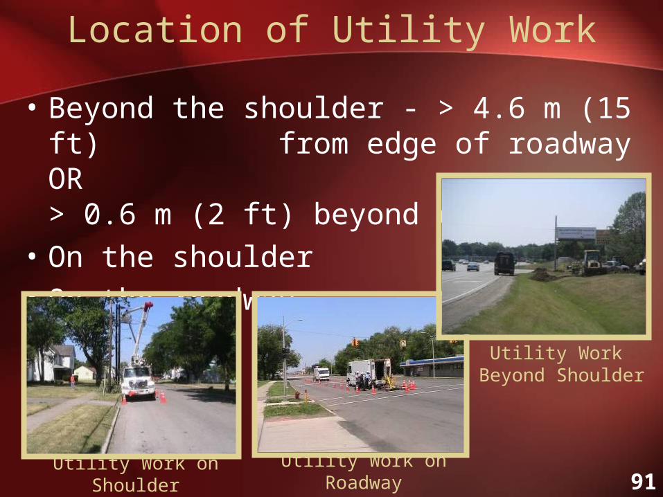
Location of Utility Work
• Beyond the shoulder - > 4.6 m (15 ft) from edge of roadway OR > 0.6 m (2 ft) beyond curb
• On the shoulder
• On the roadway
Utility Work on Shoulder
Utility Work Beyond Shoulder
Utility Work on Roadway

92
Volume and Speed of Adjacent Road
• Traffic volume of adjacent road – low volume or high volume
• Travel speed of vehicles on adjacent road – low speed ≤ 50 km/hr (30 mph) or high speed >50 km/hr (30 mph)

93
Location of Lane Closure
• Mid-Block
• Intersection – right lane on near side, left lane on near side, right lane on far side, left lane on far side, center of intersection

94
Roadway Type
• Rural vs. Urban
• Two-Lane vs. Multi-Lane
Lane Closure on Rural Two-Lane Road
Lane Closure on Urban Multi-Lane Road

95
Case Study – In-Class Exercises

96
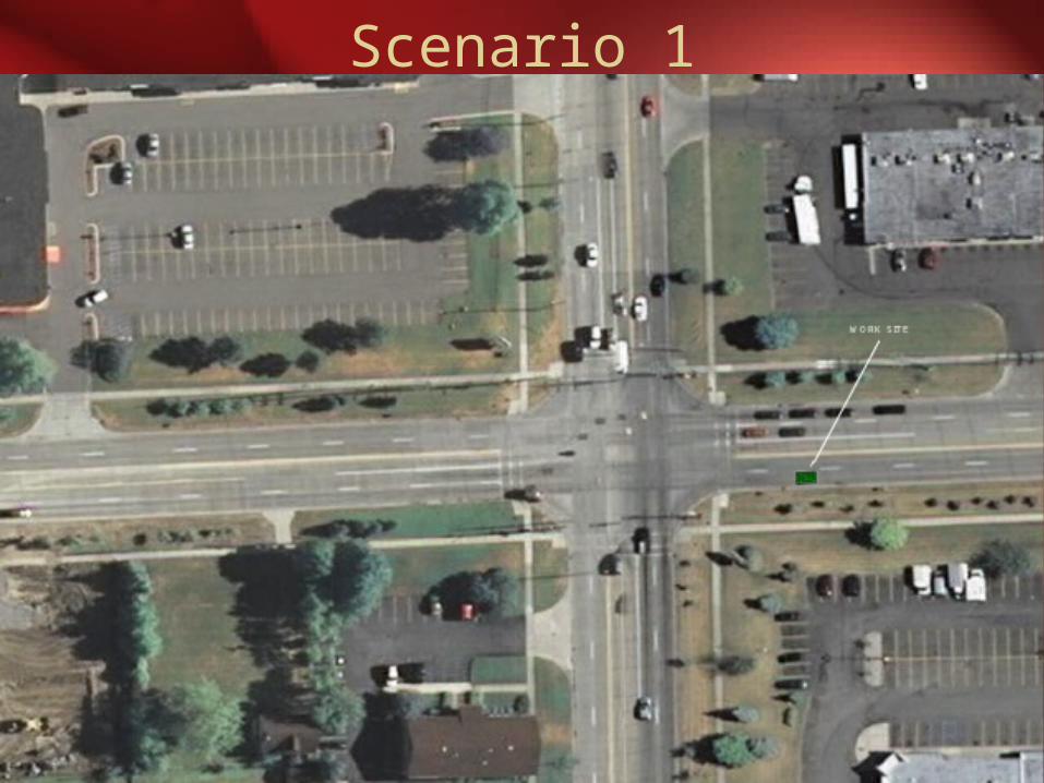
Scenario 1
• Sterling Heights, MI
• 17 Mile Road and Ryan Road
• Electrical repair work in eastbound right lane
• Speed Limit = 45 mph
• High Traffic Volume
97
Scenario 1

98
17 Mile Road
Ryan Road
Scenario 1
Speed Limit = 45 mphHigh Traffic Volume

99
Scenario 2
• Detroit, MI
• Cass Avenue north of Canfield Street
• Electrical repair work on northbound shoulder
• Speed Limit = 35 mph
• Low Traffic Volume

100
Scenario 2
WO
RK
S
ITE

101
Scenario 2
Cass AvenuePrentis Street

102
Scenario 1 Solution
17 Mile Road
Ryan Road

103
Scenario 2 Solution
Cass Avenue

104
Demonstration of Software Program
“Selection of Utility Work Zone Temporary Traffic Control Plans”

105
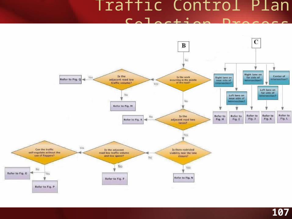
Traffic Control Plan Selection Process

106
Traffic Control Plan Selection Process
107
Traffic Control Plan Selection Process

108
Question & Answer

109
Post-Test

110
Course Evaluation