1 Table of contents - stabaload.co.za Weather M2 Installation... · 2 INTRODUCTION ... 9.2.5...
56
DYNACO Europe n.v 1 ● Table of contents M2-MEC-INST-EN-002.1.doc THE SAFEST CHOICE 1 1 Table of contents 1 TABLE OF CONTENTS ........................................................................................................... 1 2 INTRODUCTION ...................................................................................................................... 3 3 SUPPLIED ITEMS.................................................................................................................... 4 4 DIRECTIVES AND STANDARDS ........................................................................................... 5 5 SAFETY INSTRUCTIONS ....................................................................................................... 6 5.1 GENERAL INSTRUCTIONS.................................................................................................. 6 5.2 PRECAUTIONS DURING INSTALLATION................................................................................ 6 5.3 PRECAUTIONS DURING OPERATION. .................................................................................. 7 5.4 PRECAUTIONS DURING MAINTENANCE. .............................................................................. 7 5.5 PRECAUTIONS FOR THE FREQUENCY INVERTER. ................................................................ 8 5.6 AUTOMATIC OPENING DURING POWER FAILURE .................................................................. 8 5.7 AUTO/MANUAL SWITCH (DEAD MAN'S OPERATION) (OPTIONAL) ....................................... 8 6 TECHNICAL CHARACTERISTICS ......................................................................................... 9 6.1 COMPACT M2 .................................................................................................................. 9 6.1.1 Description ................................................................................................................. 9 6.1.2 Characteristics. ........................................................................................................ 10 6.1.3 Installation space required ....................................................................................... 11 6.2 ALL WEATHER M2. ........................................................................................................ 11 6.2.1 Description. .............................................................................................................. 11 6.2.2 Characteristics. ........................................................................................................ 12 6.2.3 Installation space required. ...................................................................................... 13 6.3 M2 POWER.................................................................................................................... 13 6.3.1 Description. .............................................................................................................. 13 6.3.2 Characteristics. ........................................................................................................ 14 6.3.3 Installation space required. ...................................................................................... 15 6.4 M2 FREEZER -30°C. ...................................................................................................... 15 6.4.1 Description. .............................................................................................................. 15 6.4.2 Characteristics. ........................................................................................................ 16 6.4.3 Installation space required. ...................................................................................... 17 6.5 EMERGENCY EXIT (2 IN 1) M2. ....................................................................................... 17 6.5.1 Description. .............................................................................................................. 17 6.5.2 Characteristics. ........................................................................................................ 18 6.5.3 Installation space required. ...................................................................................... 19 7 INSTALLATION ..................................................................................................................... 20 7.1 THE TOOLS REQUIRED .................................................................................................... 20 7.2 CHECKS TO BE CARRIED OUT BEFORE THE INSTALLATION OF THE DOOR. ........................... 20 7.3 FOREFRAME. ................................................................................................................. 21 7.4 ASSEMBLY ON THE FLOOR. ............................................................................................. 22 7.5 INSTALLATION OF THE SEALING CURTAIN. ........................................................................ 23 7.6 LIFTING THE DOOR ......................................................................................................... 24 7.7 ATTACHMENT TO THE WALL ............................................................................................ 25 7.8 INSTALLING THE DOOR AT RIGHT ANGLES......................................................................... 26 7.9 INSERTING THE RETAINING STRAPS INTO THE DRIVE MECHANISM....................................... 27 7.10 ELECTRICAL CONNECTIONS TO THE DOOR. ...................................................................... 28 7.10.1 Standard door. ......................................................................................................... 28 7.10.2 FREEZER door M2 -30°. ......................................................................................... 29 7.10.3 Connection of safety contact (hoist). (Optional)....................................................... 30 7.10.4 Connection of safety contact. (Ratchet spanner with extension) (Optional) ............ 31 7.11 INSTALLATION OF THE COUNTERWEIGHT.......................................................................... 32 7.12 WARRANTY AND LIABILITY............................................................................................... 33 8 COMMISSIONING.................................................................................................................. 34 8.1 MANUAL OPENING WITH THE CRANK. ............................................................................... 34 8.2 RATCHET SPANNER WITH EXTENSION. (OPTIONAL)........................................................... 35 8.3 MANUAL CHAIN HOIST. (OPTIONAL) ................................................................................. 36
Transcript of 1 Table of contents - stabaload.co.za Weather M2 Installation... · 2 INTRODUCTION ... 9.2.5...

DYNACO Europe n.v 1 ● Table of contents
M2-MEC-INST-EN-002.1.doc THE SAFEST CHOICE 1
1 Table of contents 1 TABLE OF CONTENTS........................................................................................................... 1 2 INTRODUCTION ...................................................................................................................... 3 3 SUPPLIED ITEMS.................................................................................................................... 4 4 DIRECTIVES AND STANDARDS ........................................................................................... 5 5 SAFETY INSTRUCTIONS ....................................................................................................... 6
5.1 GENERAL INSTRUCTIONS.................................................................................................. 6 5.2 PRECAUTIONS DURING INSTALLATION................................................................................ 6 5.3 PRECAUTIONS DURING OPERATION. .................................................................................. 7 5.4 PRECAUTIONS DURING MAINTENANCE. .............................................................................. 7 5.5 PRECAUTIONS FOR THE FREQUENCY INVERTER. ................................................................ 8 5.6 AUTOMATIC OPENING DURING POWER FAILURE .................................................................. 8 5.7 AUTO/MANUAL SWITCH (DEAD MAN'S OPERATION) (OPTIONAL) ....................................... 8
6 TECHNICAL CHARACTERISTICS ......................................................................................... 9 6.1 COMPACT M2.................................................................................................................. 9
6.1.1 Description ................................................................................................................. 9 6.1.2 Characteristics. ........................................................................................................ 10 6.1.3 Installation space required ....................................................................................... 11
6.2 ALL WEATHER M2. ........................................................................................................ 11 6.2.1 Description. .............................................................................................................. 11 6.2.2 Characteristics. ........................................................................................................ 12 6.2.3 Installation space required. ...................................................................................... 13
6.3 M2 POWER.................................................................................................................... 13 6.3.1 Description. .............................................................................................................. 13 6.3.2 Characteristics. ........................................................................................................ 14 6.3.3 Installation space required. ...................................................................................... 15
6.4 M2 FREEZER -30°C....................................................................................................... 15 6.4.1 Description. .............................................................................................................. 15 6.4.2 Characteristics. ........................................................................................................ 16 6.4.3 Installation space required. ...................................................................................... 17
6.5 EMERGENCY EXIT (2 IN 1) M2. ....................................................................................... 17 6.5.1 Description. .............................................................................................................. 17 6.5.2 Characteristics. ........................................................................................................ 18 6.5.3 Installation space required. ...................................................................................... 19
7 INSTALLATION ..................................................................................................................... 20 7.1 THE TOOLS REQUIRED.................................................................................................... 20 7.2 CHECKS TO BE CARRIED OUT BEFORE THE INSTALLATION OF THE DOOR. ........................... 20 7.3 FOREFRAME. ................................................................................................................. 21 7.4 ASSEMBLY ON THE FLOOR. ............................................................................................. 22 7.5 INSTALLATION OF THE SEALING CURTAIN. ........................................................................ 23 7.6 LIFTING THE DOOR ......................................................................................................... 24 7.7 ATTACHMENT TO THE WALL ............................................................................................ 25 7.8 INSTALLING THE DOOR AT RIGHT ANGLES......................................................................... 26 7.9 INSERTING THE RETAINING STRAPS INTO THE DRIVE MECHANISM....................................... 27 7.10 ELECTRICAL CONNECTIONS TO THE DOOR. ...................................................................... 28
7.10.1 Standard door. ......................................................................................................... 28 7.10.2 FREEZER door M2 -30°. ......................................................................................... 29 7.10.3 Connection of safety contact (hoist). (Optional)....................................................... 30 7.10.4 Connection of safety contact. (Ratchet spanner with extension) (Optional)............ 31
7.11 INSTALLATION OF THE COUNTERWEIGHT.......................................................................... 32 7.12 WARRANTY AND LIABILITY............................................................................................... 33
8 COMMISSIONING.................................................................................................................. 34 8.1 MANUAL OPENING WITH THE CRANK. ............................................................................... 34 8.2 RATCHET SPANNER WITH EXTENSION. (OPTIONAL)........................................................... 35 8.3 MANUAL CHAIN HOIST. (OPTIONAL) ................................................................................. 36

1 ● Table of contents DYNACO Europe n.v
2 THE SAFEST CHOICE M2-MEC-INST-EN-002.1.doc
9 MAINTENANCE......................................................................................................................37 9.1 WEEKLY MAINTENANCE OF THE FREEZER. ........................................................................37 9.2 PREVENTIVE MAINTENANCE (TO BE CARRIED OUT EVERY 6 MONTHS OR 50,000 CYCLES)....37
9.2.1 Dynalogic Controller. ................................................................................................37 9.2.2 Motor, reduction gear and encoder. .........................................................................37 9.2.3 Door panel. ...............................................................................................................37 9.2.4 Frame........................................................................................................................38 9.2.5 Infrared photocell. .....................................................................................................38 9.2.6 WDD contact detector...............................................................................................38 9.2.7 Side guides ...............................................................................................................38 9.2.8 150 mm lining at the top of the guides......................................................................38 9.2.9 Counterweight...........................................................................................................38 9.2.10 Drive mechanism. .....................................................................................................39
9.3 COMPONENTS SUBJECT TO WEAR....................................................................................39 9.4 TROUBLESHOOTING........................................................................................................40
9.4.1 The door reopens during the closing cycle...............................................................40 9.4.2 The door will not close. .............................................................................................41 9.4.3 The door remains closed/does not work...................................................................42 9.4.4 It is as if the door has too little power. ......................................................................43 9.4.5 The door is operating outside its side guides. ..........................................................44
9.5 PROCEDURE FOR REPAIRING THE DOOR PANEL ................................................................45 10 INSTALLATION CHECKLIST.............................................................................................47
10.1 INSPECTIONS OF AUTOMATIC DOORS................................................................................47 10.2 LOG BOOK......................................................................................................................48 10.3 INSPECTIONS CARRIED OUT.............................................................................................49 10.4 MAINTENANCE SCHEDULE ...............................................................................................51 10.5 INSTALLATION CHECKLIST................................................................................................53
11 INDEX..................................................................................................................................55 12 TABLE OF DRAWINGS......................................................................................................56

DYNACO Europe n.v 2 ● Introduction
M2-MEC-INST-EN-002.1.doc THE SAFEST CHOICE 3
2 Introduction Since 1987, DYNACO has concentrated its know-how on a unique and patented system of automatic, high-speed doors that have the following characteristics:
• Perfect seal
• Total safety
• Guaranteed to be self-repairing
• Wind proof
• Very high speed
• Smooth operation
DYNACO continuously develops its products to accurately meet the specific needs of every sector of the industry. DYNACO has an experienced team for design, customer advice, production, and providing service with the shortest possible lead times.
In the context of this policy of continuous development of its products, DYNACO reserves the right to change the characteristics of its products or parts, without prior notice.

3 ● Supplied items DYNACO Europe n.v
4 THE SAFEST CHOICE M2-MEC-INST-EN-002.1.doc
3 Supplied items
• Door manual.
• Control box manual
• Frequency inverter manual.
• Electrical options manual.
• Maintenance book.
• Production sheet.
DYNACO Europe n.v 4 ● Directives and standards
M2-MEC-INST-EN-002.1.doc THE SAFEST CHOICE 5
4 Directives and standards
The following guidelines and standards are followed in the construction of DYNACO doors.
98/37/EC Machinery guidelines.
89/106/EEC Construction products guideline.
89/336/EEC EMC – guideline.
73/23/EEC Guideline related to low voltage.
EN 13241-1 Industrial, commercial and garage doors without fire and smoke resistant characteristics.
Dynaco doors can be controlled in various ways. The Dynalogic control units offer a number of options for connecting hand operated and/or automatic opening controls. The choice of opening commands depends on a large number of factors, including intensity of use, the environment, and the type of traffic using the door.
DYNACO Europe offers a wide range of opening controls. The installer, in consultation with the user, can offer added value within his or her area of responsibility by selecting the most appropriate actuators.
The opening controls meet the low voltage guideline, 73/23/EEC, and the Guideline for Electro-magnetic compatibility, 89/336/EEC. For remote control using a radio frequency, guideline R&TT E, 99/5/EC, also applies.
The opening controls selected by the installer or end user must meet the same standards, and must be adapted for the use and environment in which they are to be used. They may not influence the control box. Neither must their operation in turn be impacted by environmental factors or the control unit. The control and safety components that are built-in as standard, must be replaced with identical replacement parts.
The connections, the working methods and materials used must meet the required standards listed under the guidelines set out above, or those imposed by local authorities.

5 ● Safety instructions DYNACO Europe n.v
6 THE SAFEST CHOICE M2-MEC-INST-EN-002.1.doc
5 Safety instructions
5.1 General instructions.
Please carefully read the safety instructions and the manual before starting any work.
The description below uses symbols to draw the reader's attention to the various dangers and to provide useful advice.
Indicates a potential danger to persons; please take all possible precautions against risks associated with working with electrical materials, it may have power connected.
Please follow exactly; ignoring this advice can cause a fault or a dangerous situation.
Important information.
Only to be performed by DYNACO-certified persons.
May only be performed by a technician who is authorised to operate a forklift.
5.2 Precautions during installation
• Electrocution may lead to death. Never touch parts that are 'live'. Be very careful during the installation and maintenance of electrical components of the door.
• For the safety of the user and the proper operation of the door, the door must be installed in accordance with the instructions contained in this manual.

DYNACO Europe n.v 5 ● Safety instructions
M2-MEC-INST-EN-002.1.doc THE SAFEST CHOICE 7
• Only authorised personnel may work on DYNACO doors. Personnel concerned must be properly informed about the contents of the manual, remarks and warnings regarding transport, and about the installation and commissioning of this door. Work by unauthorised personnel can bring about risks for the users. Install the door with the assistance of qualified forklift drivers and electricians.
• Installation by unauthorised personnel may lead to damage of the door components and poor operation of the door.
• Not following the manual during installation, or installation by unauthorised personnel will lead to an invalidation of the warranty.
• Please ensure that all accessories meet IEC standards.
• The equipment and accessories must be installed in accordance with the manufacturer's instructions, as well as national and other standards.
5.3 Precautions during operation.
• Electrocution may lead to death. Never touch parts that are 'live'. Be very careful during the installation and maintenance of electrical components of the door.
• For the safety of the user and the proper operation of the door, the door must be used in accordance with the instructions contained in this manual.
• Only use the door when the control box is locked.
• Ensure the safety warnings, covers and protections are kept in good condition. Safety warnings must remain visible at all times.
• Avoid all contact with moving parts.
• Sometimes, safety equipment needs to be removed for maintenance. Reinstall them after commissioning.
5.4 Precautions during maintenance.
• Electrocution may lead to death. Never touch parts that are 'live'. Be very careful during the installation and maintenance of electrical components of the door.
• Only personnel certified by DYNACO are allowed to carry out maintenance on DYNACO doors. If maintenance is carried out by persons who have not been trained by DYNACO, the warranty will be invalidated.
• All parts used in DYNACO doors have been designed for this application. Only use original DYNACO parts.
• Sometimes, safety equipment needs to be removed for maintenance. Reinstall them after commissioning.
• In case of intervention (with regard to the electrical and/or mechanical section of the installation), the power supply must be interrupted and locked.
Beware: the cables between main switch and power supply always remains live.

5 ● Safety instructions DYNACO Europe n.v
8 THE SAFEST CHOICE M2-MEC-INST-EN-002.1.doc
5.5 Precautions for the frequency inverter.
The frequency inverter.
• When a frequency inverter has power supplied to it, the electrical elements and a number of operating controls are also 'live'. Never touch these elements. This is extremely dangerous.
• When the emergency stop is activated, the frequency inverter remains 'live'. If this is a threat to the safety of the staff, the power circuit must be interrupted by locking the main switch on the control box.
• After locking the main switch, it is always necessary to wait 15 minutes before starting work. This is the time required for discharging the capacitors of the frequency inverter.
• The frequency inverter has integrated safety systems for stopping the door. A mechanical blockage, fluctuations in voltage and interruptions of the power supply can also bring the door to a stop. This is shown with a fault message on the frequency inverter screen. Lock the main switch before removing the cause of a blockage. Unlock the main switch to put the door into service again. An impulse via the ‘'Open' push button on the control box will reset the controller.
• For more detailed information, please check the manuel of the frequency inverter in the control box.
5.6 Automatic opening during power failure
For doors with the 'automatic opening during power failure' option, it is not enough to interrupt the general feed from the electricity supply, because the UPS current will continue to flow. In order to carry out work on the door, the door must be shut down completely by locking the main switch on the control box. The cable that connects the UPS with the main switch will then remain 'live'.
Consult the manual of the UPS for interrupting the current on the cable between the UPS and the main switch.
5.7 AUTO/MANUAL switch (dead man's operation) (Optional)
The door will close based on the dead man principle in the manual (Manu) mode: the Close pushbutton must remain pressed. The photocell and the WDD remain active. A single press of the 'open' button will open the door again.

DYNACO Europe n.v 6 ● Technical characteristics
M2-MEC-INST-EN-002.1.doc THE SAFEST CHOICE 9
6 Technical characteristics
Designed for a very wide range of applications, both internally and externally, every DYNACO door has its own characteristics.
DYNACO doors meet the most stringent safety requirements in every respect.
Some doors close using gravitational force and flexible ballast, others have been designed to close without ballast, by pushing or pulling the curtain up or down in the side guides.
DYNACO offers a range of doors, of which the technical details are shown in this documentation.
Explanation EN 13241-1 classification 0 1 2 3 4 5 Water permeability NPD 30 Pa 50 Pa >50 Pa Wind load NPD 300 Pa 450 Pa 700 Pa 1,000 Pa >1,000 Pa
Wind permeability NPD 24m³/h/m² 12m³/h/m² 6m³/h/m² 3m³/h/m² 1,5m³/h/m²
NPD: No performance determined
The required built-in space for an M2 door
All dimensions indicated are net: it will be necessary to add the required space for installation and maintenance. Reduced dimensions: on request. • M2 without covers:
Top +150, motor side (at motor level) +150, other side +100, front +500.
• M2 with covers:
Top +200, motor side (at motor level) +250, other side +200, front +500.
6.1 Compact M2
6.1.1 Description Intended use: for indoor installation. Maximum dimensions: W 5,500 mm x H 5,500 mm. Opening and closing speed: 1.2 m/s. Optional other opening speeds available on request. Up to 20 m²: 2.4 m/s; 20 up to 24 m²: 2 m/s; more than 24 m²: 1.6 m/s Type of operation: interlocking, i.e. without ballast Structure: finished using 80 x 40 x 3 mm U-profiles in steel, galvanised before cutting and creasing, or 80 x 40 x 2 mm in Inox (option). Wind-up drum in steel. Diameter 102 x 2 mm and shafts in steel. The drum is not visible: the door panel covers the drum, even when the door is closed. Side guides in polyethylene (PE-UHMW 1000); 23 x 40 mm in outside diameter, sprung. Door curtain in reinforced PVC (900 g/m²) extremely durable. RAL colours: yellow (1003), grey (7035), blue (5002), red (3000), green (6005), orange (2004), white (9010) or black (9005) and equipped with lateral support cords (diameter 16 x 12.5 mm)

6 ● Technical characteristics DYNACO Europe n.v
10 THE SAFEST CHOICE M2-MEC-INST-EN-002.1.doc
Motor 4 - phase without brake, controlled by a frequency inverter. Capacity: 0.75 kW for a door panel area of up to 14 m², 1.5 kW (for larger surface areas). Voltage: 3 x 230/400 V. IP 65 protection level Gearbox: With worm and worm wheel, size 50 for a 0.75 kW motor and a reduction ratio of 1/7; size 63 for 1.5 kW. Compact control panel in painted steel with lockable main fuse, a general isolation switch, an adjustable timer for closing, a push button for opening and a reset after a power interruption, as well as an emergency stop button. Protection level: IP 54. The length of the electrical cables between the various electrical components (motor and other standard components) allows the control panel to be placed approximately 1,200 mm above floor level and 1,000 mm from the door, on the side where the motor is located. Positioning limit switch: is determined by the absolute coding system at the back of the motor. Detectors supplied with the standard equipment: A proximity detector using an infrared beam, installed approximately 20 mm from the axis of the door, it opens the door immediately if it registers the presence of pedestrians or vehicles, and keeps the door open as long as that presence keeps registering. Level of the beam: 300 mm above floor level. Wireless DYNACO Detector (WDD): this is a wireless obstruction detection system comprising a transmitter in the bag at the bottom of the door and a receiver in the control panel. The system uses an “open loop” system: when the sensor touches an obstacle, the transmitter switches from its standby mode and sends a signal to the receiver, which immediately opens the door. The so-called “open loop” system means that the lithium battery of the transmitter has a very long life because it is only used when the feeler touches an obstacle; at all other times; the transmitter is inactive. Power supply: single phase, 220 to 240 V. Frequency: 50 – 60 Hz. Fuse to be provided by the customer for the power supply: 16 A for a 0.75 kW motor; 25 A for a 1.5 kW motor.
6.1.2 Characteristics.
Properties Standard Test in
accordance with
Results
Water permeability EN 12425 EN 12489 Class 1 Wind load EN 12424 EN 12444 Class 2* Wind permeability EN 12426 EN 12427 Class 1 Safe openings EN 12453 EN 12445 Pass Mechanical resistance EN 12604 EN 12605 Pass Unintended movements EN 12604 EN 12605 Pass Thermal resistance EN 12428 EN 12428 6,02W/m²K Performance (cycles) EN 12604 EN 12605 750.000 * Indicated Class for wind load applies to maximum sizes. For doors
up to B4500 x H5500: Class 3

DYNACO Europe n.v 6 ● Technical characteristics
M2-MEC-INST-EN-002.1.doc THE SAFEST CHOICE 11
6.1.3 Installation space required
Figure 6-1: Compact M2 installation space required.
* 650 if drum hood and H > 4000 **650 if drum hood and H > 4000 ***650 if drum hood and H > 4000
6.2 All Weather M2.
6.2.1 Description. Intended use: for internal or external installation. Maximum dimensions: W 5,500 mm x H 5,500 mm. Opening and closing speed: 1.2 m/s. Optional other opening speeds available on request. Up to 15 m²: 2.4 m/s; from 15 to 18 m²: 2 m/s; more than 18 to 23 m²: 1.6 m/s Type of operation: interlocking, i.e. without ballast Structure: Realised by using 80 x 40 x 3 mm U-profiles in steel, galvanised before cutting and creasing, or 80 x 40 x 2 mm in stainless steel (option). Wind-up drum In steel, diameter 102 x 2 mm, and shafts in steel. The drum is not visible: the door panel covers the drum, even when the door is closed. Side guides in polyethylene (PE-UHMW 1000); 23 x 40 mm in outside diameter, sprung, reinforced at the bottom. Door curtain in reinforced PVC (900 g/m²) very durable, RAL colours: yellow (1003), grey (7035), blue (5002), red (3000), green (6005), orange (2004), white (9010) or black (9005) and equipped with lateral support cords (diameter 16 x 12.5 mm).
Reduced: 370 if H ≤ 4000
6 ● Technical characteristics DYNACO Europe n.v
12 THE SAFEST CHOICE M2-MEC-INST-EN-002.1.doc
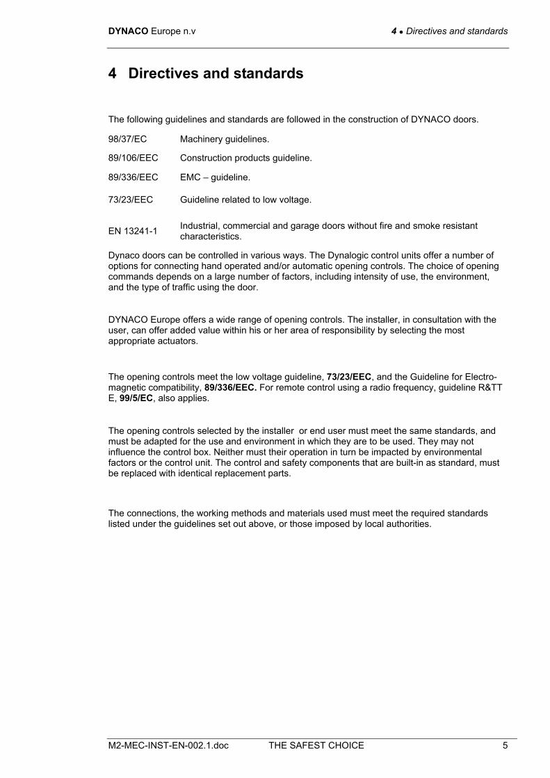
Motor 4 - phase without brake, controlled by a frequency inverter. Capacity: 1.5 kW. Voltage: 3 x 230/400 V. IP 65 protection level Gearbox: with worm and worm wheel, size 63, and a reduction ratio of 1/7. Compact control panel in painted steel with lockable main fuse, a general isolation switch, an adjustable timer for closing, a push button for opening and a reset after a power interruption, as well as an emergency stop button. Protection level: IP54. The length of the electrical cables between the various electrical components (motor and other standard components) allows the control panel to be placed approximately 1,200 mm above floor level and 1,000 mm from the door, on the side where the motor is located. Positioning limit switch: is determined by the absolute coding system at the back of the motor. Detectors supplied with the standard equipment: A proximity detector using an infrared beam, installed approximately 20 mm from the axis of the door panel, opens the door immediately if it registers the presence of pedestrians or vehicles, and keeps the door open as long as that presence keeps registering. Level of the beam: 300 mm above floor level. Wireless DYNACO Detector (WDD): This is a wireless obstruction sensor system comprising a transmitter in the bag at the bottom of the door and a receiver in the control panel. The system uses an “open loop” system: when the sensor touches an obstacle, the transmitter switches from its standby mode and sends a signal to the receiver, which immediately opens the door. The so-called “open loop” system means that the lithium battery of the transmitter has a very long life because it is only used when the feeler touches an obstacle; at all other times; the transmitter is inactive. Power supply: single phase, 220 to 240 V Frequency: 50 – 60 Hz. Fuse for the power supply to be provided by the customer: 25 A.
6.2.2 Characteristics.
Properties Standard Test in
accordance with
Results
Water permeability EN 12425 EN 12489 Class 3
Wind load EN 12424 EN 12444 Class 4*
Wind permeability EN 12426 EN 12427 Class 1
Safe openings EN 12453 EN 12445 Pass
Mechanical resistance EN 12604 EN 12605 Pass
Unintended movements EN 12604 EN 12605 Pass
Thermal resistance EN 12428 EN 12428 6,02W/m²K
Performance (cycles) EN 12604 EN 12605 750.000 * Indicated Class for wind load applies to maximum sizes. For doors up
to W 5,000 x H 5,500: Class 5

DYNACO Europe n.v 6 ● Technical characteristics
M2-MEC-INST-EN-002.1.doc THE SAFEST CHOICE 13
6.2.3 Installation space required.
Figure 6-2: All Weather.M2 installation space required
* 650 if drum hood and H > 4,000 ** 600 if drum hood and H > 4,000 *** 650 if drum hood and H > 4,000
6.3 M2 Power.
6.3.1 Description. Intended use: for internal or external installation Maximum dimensions: W 5,500 mm x H 5,500 mm. Opening and closing speed: 1.2 m/s. Optional other opening speeds available on request. Up to 17m²: 2.4 m/s; up to 21 m²: 2 m/s; from 21 to 25 m²: 1.6 m/s Type of operation: interlocking, i.e. without ballast Structure: finished using 80 x 40 x 3 mm U-profiles in steel, galvanised before cutting and creasing, or 80 x 40 x 2 mm in stainless steel (option). Wind-up drum In steel, diameter 102 x 2 mm, and shafts in steel. The drum is not visible: the door panel covers the drum, even when the door is closed. Side guides in polyethylene (PE-UHMW 1000); 23 x 40 mm in outside diameter, sprung, reinforced at the bottom over 300 mm. Door curtain in reinforced PVC (900 g/m²) very durable, in RAL colours: yellow (1003), grey (7035), blue (5002), red (3000), green (6005), orange (2004), white (9010) or black (9005) and equipped with lateral support cords (diameter 16 x 12.5 mm). Motor 4 - phase without brake, controlled by a frequency inverter. Capacity: 1.5 kW. Voltage: 3 x 230/400 V. IP 65 protection level Gearbox: with worm and worm wheel, size 63, and a reduction ratio of 1/7. Compact control panel in painted steel with lockable main fuse, a general isolation switch, an adjustable timer for closing, a push button for opening and a reset after a power interruption, as
Reduced: 370 if H ≤ 4000
6 ● Technical characteristics DYNACO Europe n.v
14 THE SAFEST CHOICE M2-MEC-INST-EN-002.1.doc
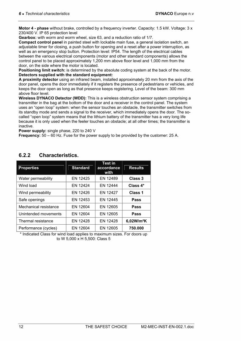
well as an emergency stop button. Protection level: IP54. The length of the electrical cables between the various electrical components (motor and other standard components) allows the control panel to be placed approximately 1,200 mm above floor level and 1,000 mm from the door, on the side where the motor is located. Positioning limit switch: is determined by the absolute coding system at the back of the motor. Detectors supplied with the standard equipment: A proximity detector using an infrared beam, installed at ± 20 mm from the axis of the door panel, opens the gate immediately if it registers the presence of pedestrians or vehicles, and will hold the door open as long as that presence registers. Level of the beam: 300 mm above floor level. Wireless DYNACO Detector (WDD): this is a wireless obstruction sensor system comprising a transmitter in the bag at the bottom of the door and a receiver in the control panel. The system uses an “open loop” system: when the sensor touches an obstacle, the transmitter switches from its standby mode and sends a signal to the receiver, which immediately opens the door. The so-called “open loop” system means that the lithium battery of the transmitter has a very long life because it is only used when the feeler touches an obstacle; at all other times; the transmitter is inactive. Power supply: Single phase, 220 to 240 V Frequency: 50 – 60 Hz. Fuses to be provided by the customer for the power supply: 25 A.
6.3.2 Characteristics.
Properties Standard Test in
accordance with
Results
Water permeability EN 12425 EN 12489 Class 1
Wind load EN 12424 EN 12444 Class 3*
Wind permeability EN 12426 EN 12427 Class 2
Safe openings EN 12453 EN 12445 Pass
Mechanical resistance EN 12604 EN 12605 Pass
Unintended movements EN 12604 EN 12605 Pass
Thermal resistance EN 12428 EN 12428 6,02W/m²K
Performance (cycles) EN 12604 EN 12605 750.000
* Indicated Class for wind load applies to maximum sizes. For doors up to W 4,000 x H 5,500: Class 4

DYNACO Europe n.v 6 ● Technical characteristics
M2-MEC-INST-EN-002.1.doc THE SAFEST CHOICE 15
6.3.3 Installation space required.
Figure 6-3: Power M2 installation space required.
* 650 if drum hood and H > 4,000 ** 600 if drum hood and H > 4,000 *** 650 if drum hood and H > 4,000
6.4 M2 Freezer -30°C.
6.4.1 Description. Intended use: for indoor installation. Maximum dimensions: W 4,500 mm x H 4,500 mm. Opening speed: 2.4 m/s Closing speed: 1.2 m/s Type of operation: interlocking, i.e. without ballast Structure finished using 80 x 40 x 3 mm U-profiles in steel, galvanised prior to cutting and creasing (optionally 80 x 40 x 2 mm in stainless steel) protected by a layer of polyethylene to create a thermal barrier between the structure of the building and the door and provided with heating tapes to stop ice formation, which could impede the operation of the door. Standard: motor cover and cladding of the door posts (protection of the heating tapes). PLEASE NOTE: despite the heating tapes, ice formation may sometimes occur in some locations. We recommend that you carefully remove this ice. We recommend that the user appoint a person within the user's organisation who will be responsible for the maintenance of the M2 Freezer. Protection- and lintel sealing sheet. Reinforced sealing at the bottom inclusive. Wind-up drum In steel, diameter 102 x 2 mm, and shafts in steel. The drum is not visible: the door panel covers the drum, even when the door is closed. Side guides in polyethylene (PE-UHMW 1000); 23 x 40 mm in external diameter on springs, equipped with heating tapes that prevent ice-formation on the guides.
Reduced: 370 if H ≤ 4000
6 ● Technical characteristics DYNACO Europe n.v
16 THE SAFEST CHOICE M2-MEC-INST-EN-002.1.doc
Door curtain in reinforced PVC (900 g/m²) very durable. RAL colours: yellow (1003), grey (7035), blue (5002), red (3000), green (6005), orange (2004), white (9010) or black (9005) and equipped with lateral support cords (diameter 16 x 12.5 mm). Motor 4 - phase without brake, controlled by a frequency inverter. Capacity: 1.5 kW. Voltage: 3 x 230/400 V. IP 65 protection level Gearbox: with worm and worm wheel, size 63, and a reduction ratio of 1/7. Compact control panel in painted steel with lockable main fuse, a general isolation switch, an adjustable timer for closing, a push button for opening and a reset after a power interruption, as well as an emergency stop button. Protection level: IP54. The length of the electrical cables between the various electrical components (motor and other standard components) allows the control panel to be placed approximately 1,200 mm above floor level and 1,000 mm from the door, on the side where the motor is located. Positioning limit switch: is determined by the absolute coding system at the back of the motor. Detectors supplied with the standard equipment: A proximity detector using an infrared beam, installed approximately 20 mm from the axis of the door panel, it opens the door immediately if it registers the presence of pedestrians or vehicles, and keeps the door open as long as that presence keeps registering. Level of the beam: 300 mm above floor level. Wireless DYNACO Detector (WDD): this is a wireless obstruction sensor system comprising a transmitter in the bag at the bottom of the door and a receiver in the control panel. The system uses an “open loop” system: when the sensor touches an obstacle, the transmitter switches from its standby mode and sends a signal to the receiver, which immediately opens the door. The so-called “open loop” system means that the lithium battery of the transmitter has a very long life because it is only used when the feeler touches an obstacle; at all other times; the transmitter is inactive. Power supply: single phase, 220 to 240 V Frequency: 50 – 60 Hz. Fuses to be provided by the customer for the power supply: 25 A.
6.4.2 Characteristics.
Properties Standard Test in
accordance with
Results
Water permeability EN 12425 EN 12489 Class 1
Wind load EN 12424 EN 12444 Class 3*
Wind permeability EN 12426 EN 12427 Class 1
Safe openings EN 12453 EN 12445 Pass
Mechanical resistance EN 12604 EN 12605 Pass
Unintended movements EN 12604 EN 12605 Pass
Thermal resistance EN 12428 EN 12428 6,02W/m²K
Performance (cycles) EN 12604 EN 12605 750.000

DYNACO Europe n.v 6 ● Technical characteristics
M2-MEC-INST-EN-002.1.doc THE SAFEST CHOICE 17
6.4.3 Installation space required.
Figure 6-4: Freezer M2 installation space required.
6.5 Emergency Exit (2 in 1) M2.
6.5.1 Description. Intended use: for internal or external installation. Maximum dimensions: W 5,500 mm x H 5,500 mm. Note: the “sas operation” option does not apply to this type of door. Opening speed: 1.2 m/s Closing speed: 0.6 m/s Type of operation: interlocking, i.e. without ballast Structure: finished using 80 x 40 x 3 mm U-profiles in steel, galvanised before cutting and creasing, or 80 x 40 x 2 mm in stainless steel (option). Front frame in galvanised steel or Inox (option), in profiles measuring 120 x 80 x 3 mm, supplied as standard (to ensure the sliding heads to not hit the lintel). Must be installed: DYNACO will not issue a guarantee for doors that have not been installed with the front frame that is supplied with the door. Wind-up drum In steel, diameter 102 x 2 mm, and shafts in steel. The drum is not visible: the door panel covers the drum, even when the door is closed. Side guides in polyethylene (PE-UHMW 1000); 23 x 40 mm in outside diameter, sprung, reinforced at the bottom over 300 mm. Door curtain in reinforced PVC (900 g/m²) very durable. RAL colours: yellow (1003), grey (7035), blue (5002), red (3000), green (6005), orange (2004), white (9010) or black (9005) and equipped with lateral support cords (diameter 16 x 12.5 mm). Emergency exit: A cut-out in the shape of a T in the centre of the door panel, kept together by zippers allows the two symmetrical “flaps” to provide free access to an emergency exit. This can
Reduced: 370 if H ≤ 4000
6 ● Technical characteristics DYNACO Europe n.v
18 THE SAFEST CHOICE M2-MEC-INST-EN-002.1.doc
be easily operated by pushing the specified place (push here for emergency exit) at approximately 1,100 mm from the floor. The zipper is not locked at this place, which means that it can be immediately opened. The dimensions of the emergency exit are as follows: height is always 2,050 mm; standard width: the width of the door opening is at least 400 mm with a maximum passage width of 4,000 mm or, therefore, 2 flaps measuring 2,000 mm. Approved in France, Belgium and Switzerland. We will send you a copy of the relevant certificates on request. Motor, 4 - phase without brake, controlled by a frequency inverter. Capacity: 1.5 kW. Voltage: 3 x 230/400 V. Protection degree IP 65. Gearbox with worm and worm wheel, size 63, and a reduction ratio of 1/7. Compact control panel in painted steel with lockable main fuse, a general isolation switch, an adjustable timer for closing, a push button for opening and a reset after a power interruption, as well as an emergency stop button. Protection level: IP54. The length of the electrical cables between the various electrical components (motor and other standard components) allows the control panel to be placed approximately 1,200 mm above floor level and 1,000 mm from the door, on the side where the motor is located. Positioning limit switch: is determined by the absolute coding system at the back of the motor. Detectors supplied with the standard equipment: A proximity detector using an infrared beam, installed approximately 20 mm from the axis of the door panel, it opens the door immediately if it registers the presence of pedestrians or vehicles, and keeps the door open as long as that presence keeps registering. Level of the beam: 300 mm above floor level. Detector monitoring the proper unwinding of the door panel: This detector is located on sealing cross beam and checks whether any loops may be forming at wind-up drum level when there are obstructions in the path of the door panel that prevent the door from closing normally. This detector opens the door at the same time. Wireless DYNACO Detector (WDD): this is a wireless obstruction sensor system comprising a transmitter in the bag at the bottom of the door and a receiver in the control panel. The system uses an “open loop” system: when the sensor touches an obstacle, the transmitter switches from its standby mode and sends a signal to the receiver, which immediately opens the door. The so-called “open loop” system means that the lithium battery of the transmitter has a very long life because it is only used when the feeler touches an obstacle; at all other times; the transmitter is inactive. Power supply: Single phase, 220 to 240 V. Frequency: 50 – 60 Hz. Fuses to be provided by the customer for the power supply: 25 A.
6.5.2 Characteristics.
Properties Standard Test in
accordance with
Results
Water permeability EN 12425 EN 12489 Class 1
Wind load EN 12424 EN 12444 Class 1*
Wind permeability EN 12426 EN 12427 Class 1
Safe openings EN 12453 EN 12445 Pass
Mechanical resistance EN 12604 EN 12605 Pass
Unintended movements EN 12604 EN 12605 Pass
Thermal resistance EN 12428 EN 12428 6,02W/m²K
Performance (cycles) EN 12604 EN 12605 750.000 * Indicated Class for wind load applies to maximum sizes. For doors
up to W 3,500 x H 5,500: Class 2

DYNACO Europe n.v 6 ● Technical characteristics
M2-MEC-INST-EN-002.1.doc THE SAFEST CHOICE 19
6.5.3 Installation space required.
Figure 6-5: Emergency exit (2 in 1) M2 installation space required.
Reduced: 370 if H ≤ 4000

7 ● Installation DYNACO Europe n.v
20 THE SAFEST CHOICE M2-MEC-INST-EN-002.1.doc
7 Installation
7.1 The tools required
1 Measuring tape 1 Hammer
1 Water level 1 Set of screw drivers
1 Pencil 1 Wrench, 6 – 14 mm
1 Combination pliers 1 Extension cord
1 Cutting nippers 1 Electric screwdriver
1 Wire strippers 1 Electric drill
1 Multimeter 1 A set of metal drill 6 – 18 mm
4 500 mm clamps 1 Hammer drill
2 1200 mm clamps 1 A set of concrete drill 6 – 16 mm
1 Silicon gun
7.2 Checks to be carried out before the installation of the door.
1 Please contact the person responsible at the customer's place of business – check access conditions and prevailing safety regulations.
2 First check the dimensions of the construction opening – The exact measurements can be found on the production sheet supplied with the door. (Packing list)
3 Carefully unpack the door and check the various components against the packing list.
Materials required for assembly of the various components are part of the delivery.
The fastening materials for attaching the door to the wall must be chosen to suit the loading and substrata. These fasteners are not included in the delivery.

DYNACO Europe n.v 7 ● Installation
M2-MEC-INST-EN-002.1.doc THE SAFEST CHOICE 21
7.3 Foreframe.
Foreframe dimensions: the clear opening of the foreframe is the same of the door width. The height of the foreframe depends on the door type
Door type X X1
D311 H + 390
D313 H + 400
M2 < 4000 H + 475
M2 > 4000 H + 635
M2 Reduced lintel H + 345
M2 Without drum cover H + 365
M3 H + 485 H + 675
D121 H + 450
D501<4000 H + 430
D501>4000 H + 615
Figure 7-1: Dimensions foreframe
H = free door height
.
W = door width
Only for M3

7 ● Installation DYNACO Europe n.v
22 THE SAFEST CHOICE M2-MEC-INST-EN-002.1.doc
7.4 Assembly on the floor.
Install both doorposts on the motor / drum / curtain unit.
Figure 7-2: Assembly on the floor.

DYNACO Europe n.v 7 ● Installation
M2-MEC-INST-EN-002.1.doc THE SAFEST CHOICE 23
7.5 Installation of the sealing curtain.
Standard with cleanroom and freezer applications, optional for all other models.
Attach the sealing curtain using a flat batten (20 x 3 mm) and self-drilling screws (3.5 x 16 ) to the sealing profile.
Figure 7-3:Iinstallation of sealing curtain.
Once the door has been attached to the wall, the sealing curtain must be attached to the wall with a flat batten (20 x 3 mm).
Figure 7-4: Attaching sealing curtain to the wall.

7 ● Installation DYNACO Europe n.v
24 THE SAFEST CHOICE M2-MEC-INST-EN-002.1.doc
7.6 Lifting the door
Protect the drum and the curtain during the installation of the door.
Lift the door and take it to the construction opening.
Figure 7-5: Lifting of the door.

DYNACO Europe n.v 7 ● Installation
M2-MEC-INST-EN-002.1.doc THE SAFEST CHOICE 25
7.7 Attachment to the wall
Check that the floor is level. The classifications indicated in accordance with EN 13241-1, can only be achieved on a levelled floor. Place the entire structure around the construction opening.
Please ensure that the parts are at level/plumb (drum, sealing profile and doorposts)
Figure 7-6: Fastening to the wall
B = The inner dimension between the doorposts
The attachment of the door posts to the wall has to be done correctly. All attachment points have to be used.

7 ● Installation DYNACO Europe n.v
26 THE SAFEST CHOICE M2-MEC-INST-EN-002.1.doc
7.8 Installing the door at right angles.
Figure 7-7: Installing the door at right angles.

DYNACO Europe n.v 7 ● Installation
M2-MEC-INST-EN-002.1.doc THE SAFEST CHOICE 27
7.9 Inserting the retaining straps into the drive mechanism.
Remove the protective packaging of the winding drum without damaging the door panel. At the same time, insert the first cog of both retaining straps into the reintroduction block, right up against the drive wheel.
Using the crank from the control panel, let the door come down manually until the bottom of the door panel is exactly above the reintroduction block. Please check if the retaining straps are at the same level.
Figure 7-8: Inserting the retaining straps into the drive mechanism.
Figure 7-9: Door panel must be straight after insertion of the retaining straps.

7 ● Installation DYNACO Europe n.v
28 THE SAFEST CHOICE M2-MEC-INST-EN-002.1.doc
7.10 Electrical connections to the door.
7.10.1 Standard door.
Install the control panel at the location agreed with the user.
Check if the main power supply complies with the connections of the transformer, motor and frequency inverter. Modify, if necessary.
Connect in the following order as per the electrical diagram and the specific notes supplied with the door:
• The motor.
• The encoder.
• The safety equipment, such as the photocell, the proximity sensor, etc.
• The various operating controls.
• Activate the emergency stop button and check whether the main switch is off.
• Make sure that the power cable is not “live” and connect the control panel to the mains power supply.
• For more information, see DYNALOGIC II OR III manual
The mounting of the photocell depends on the chosen options.
Figure 7-10: Electrical connection.

DYNACO Europe n.v 7 ● Installation
M2-MEC-INST-EN-002.1.doc THE SAFEST CHOICE 29
7.10.2 FREEZER door M2 -30°.
Figure 7-11: Connecting power to the FREEZER door.
Connection of the heating cable:
- Side guides
- Door posts
- Sealing profile
- Motor

7 ● Installation DYNACO Europe n.v
30 THE SAFEST CHOICE M2-MEC-INST-EN-002.1.doc
7.10.3 Connection of safety contact (hoist). (Optional)
Figure 7-12: Connecting power to the safety contact (hoist)

DYNACO Europe n.v 7 ● Installation
M2-MEC-INST-EN-002.1.doc THE SAFEST CHOICE 31
7.10.4 Connection of safety contact. (Ratchet spanner with extension) (Optional)
Figure 7-13: Connection of safety contact (Ratchet spanner with extension)

7 ● Installation DYNACO Europe n.v
32 THE SAFEST CHOICE M2-MEC-INST-EN-002.1.doc
7.11 Installation of the counterweight.
Open the door fully, using the crank in the control panel.
Attach the belt to the shaft of the winding drum by using two M6 x 12 counter-sunk screws. Wind the belt around the shaft, noting the direction of rotation. (please see figure below).
Pull the belt around the back of the pulley, without twisting it. Attach the belt to the counterweight, using the attachment plate and the bolts. At rest, the counterweight will hang 500 mm above the floor.
Please ensure that the counterweight does not catch on anything whilst the door is being operated. The door panel must not be wound too tightly around the drum. However, if it is wound up to loosely, you must start from the beginning, and slightly increase the diameter. When the door is closed, and the mains is switched off, the curtain should not move by itself. If not decrease the counterweight belt diameter.
Figure 7-14: Installation of the counterweight

DYNACO Europe n.v 7 ● Installation
M2-MEC-INST-EN-002.1.doc THE SAFEST CHOICE 33
7.12 Warranty and liability
Warranty claims will only be taken into consideration if the door was being operated and treated correctly. In the event of unauthorised repairs and modification to the construction and the operation of the door, the warranty will be invalidated. This rule also applies to damage resulting from defects that are the consequence of not observing the operating instructions or of inadequate maintenance of the door.

8 ● Commissioning DYNACO Europe n.v
34 THE SAFEST CHOICE M2-MEC-INST-EN-002.1.doc
8 Commissioning
8.1 Manual opening with the crank.
Lock the main switch (using a padlock): take the crank from its support under the controlbox. Insert the six-sided part of the crank into the opening under the motor and turn in one direction or the other direction to open or close the door. Put the crank back on its support under the controlbox and unlock the main switch
Figure 8-1: Manual opening with crank
To open.
M2, M3, D501 Clockwise
D311, D313, D121 Counter clockwise

DYNACO Europe n.v 8 ● Commissioning
M2-MEC-INST-EN-002.1.doc THE SAFEST CHOICE 35
8.2 Ratchet spanner with extension. (Optional)
Lock the main switch (using a padlock) Fit the extension piece to the ratchet spanner and insert the extension piece into the motor at the correct location. Wind the door to the open or closed position. Unlock the main switch.
Figure 8-2:
Ratchet spanner with
extension.
1 and 2: optional pieces supplied with the door.
The ratchet must be in place before activating the door.
After manual operation, you must switch on the main switch again and open the door with the reset button on the control panel.
1
2

8 ● Commissioning DYNACO Europe n.v
36 THE SAFEST CHOICE M2-MEC-INST-EN-002.1.doc
8.3 Manual chain hoist. (Optional)
First, pull the red handle down. This will interrupt a safety circuit. The safety circuit has the same function as the emergency stop. This will prevent the motor from starting unexpectedly during manual operation. After that, you will be able to pull the chain in either direction, closing or opening the door.
Figure 8-3: Operating the manual hoist
After use: disconnect the chain hoist with the green handle and reset the door by pushing the “open” button in the control panel.
Red
GreenDoor open

DYNACO Europe n.v 9 ● Maintenance
M2-MEC-INST-EN-002.1.doc THE SAFEST CHOICE 37
9 Maintenance
9.1 Weekly maintenance of the freezer.
• Operation of the heating tapes.
• Operation of the safety circuit fuse.
• Timing adjustment for automatic opening.
• Remove ice formation in the top and bottom seals.
• prevent ice formation on the door panel.
9.2 Preventive maintenance (to be carried out every 6 months or 50,000 cycles).
9.2.1 Dynalogic Controller. • Condition of the electrical cables.
• Condition of connections.
• Condition of cable gland.
• Attachment of cover.
• Sealing of cover.
• Operation of the opening controls.
9.2.2 Motor, reduction gear and encoder. • Condition of installation: vibration dampers, safety cable, motor seals and attachment to the
motor shaft
• Condition of connections and wiring
• Checking the reduction gear seals: grease if necessary.
• Encoder: condition of battery, cable and connector to controller
9.2.3 Door panel. • Sufficient tension on the door panel.
• Condition of all welds.
• Condition of the side retaining straps:
- Bead: continuity lubrication, wearing - Zippers (M2, M3): teeth present, condition of rubber, lubrication, wearing - D501: lubrication, wearing
• Clean the door panel and the windows with a soft cloth soaked in water, if necessary mixed with a soft cleaning agent.
• Seal with floor is OK.

9 ● Maintenance DYNACO Europe n.v
38 THE SAFEST CHOICE M2-MEC-INST-EN-002.1.doc
Never use solvents or sharp objects to clean the door panel.
9.2.4 Frame. • Condition of the door posts.
• Attachment of the door and its components
• Condition of the bearings, drive mechanism and drum.
9.2.5 Infrared photocell. • Correct operation.
• Correct adjustment.
• Cleaning the photocell, transmitter and receiver.
9.2.6 WDD contact detector. • Operation of WDD.
9.2.7 Side guides • Tidy and closed wings of the side guides.
• All screws and springs are present.
• Flexible curtain is able to move unimpeded.
• Please check that the various elements are uninterrupted (side guides, upper part of the side guides, reintroduction block).
9.2.8 150 mm lining at the top of the guides. • Check regularly and replace when necessary.
9.2.9 Counterweight. • Condition of the counterweight belt.
• Condition and attachment of the counterweight guides.
• Condition and attachment of the counterweight roll.

DYNACO Europe n.v 9 ● Maintenance
M2-MEC-INST-EN-002.1.doc THE SAFEST CHOICE 39
9.2.10 Drive mechanism.
• Attachment of the sprocket wheels to the shaft
• Condition of the sprocket wheels
• Condition A & B profiles.
• Condition of the reintroduction blocks
• Clearance of drive mechanism
• Lubrication shaft – gearwheel (M3)
Figure 9-1: A & B drive mechanism profiles
9.3 Components subject to wear.
• Guides and 150 mm lining.
• A and B profiles (only for M2 and M3)
• Lateral retaining straps.
• Motor/reduction gear.
• Drive unit components.
• WDD profile.
• WDD transmitter battery.
• Bag at the bottom of the door.
• Top sealing flap.
• Counterweight belt and roller

9 ● Maintenance DYNACO Europe n.v
40 THE SAFEST CHOICE M2-MEC-INST-EN-002.1.doc
9.4 Troubleshooting
9.4.1 The door reopens during the closing cycle.
Has the door been fitted with a radar?
YES
- Check the attachment of the radar unit to prevent vibration. - Change the range of the radar unit to ensure that no movement in the door is detected. - Reduce the sensitivity.
NO
Has the door been fitted with an HF
transmitter?
YES
The receiver can be affected by a source other than the transmitter: change the code.
NO
Does the photocell function correctly?
NO
Check the photocell for alignment and visibility.
YES
Has the deactivation of the photocell been adjusted correctly?
NO
Check the deactivation of the photocell and adjust if necessary
YES
Is the WDD activated during the closing
cycle?
YES
-Is there an obstacle in the door opening? -Check whether the WDD is functioning -Check whether the WDD has been attached properly
YES
Only for D3xx. Is the DBD activated
during the closing cycle?
YES
See chapter DBD
YES
Does the controller show an error code?
YES
Consult the manual for the controller.
NO
Contact your supplier.

DYNACO Europe n.v 9 ● Maintenance
M2-MEC-INST-EN-002.1.doc THE SAFEST CHOICE 41
9.4.2 The door will not close.
1. Power supply
phases available at the control
panel.
NO
Check the power supply.
YES
Are the operating controls inactive?
Has the emergency stop been unlocked?
Unlock the emergency stop.
NO
YES
NO
YES
- Check whether any of the opening
controls is blocked (button, pull cord), of
poorly installed (photocell, radar).
- The induction loop may be influenced by other magnetic
fields: limit the length of the connecting cable between the
loops and the detector. Remove
the electrical cables and check whether
they have been braided correctly. - Check whether
there are any metal objects on the loops.
Have the main switch and
safety switches been switched
on?
NO
Switch on the main switch
and/or the safety switch.
Has the circuit
breaker of the heating tapes
been set?
NO
Check the heating tapes and reset the
circuit breaker
YES YES
Has the handle been attached to
the support?
NO Position the handle in the correct place.
Does the controller
show an error code?
YES
Consult the manual for the controller
YES NO
Has the automatic/manu
al selector switch been set to automatic?
NO
Set the switch to automatic. Contact your
supplier.
YES
Does the photocell work
properly?
NO
YES
- Check whether the transmitter and receiver are aligned with each other.
- Clean the transmitter and receiver lenses. - Readjust the sensitivity of the amplifier.
- Check the wiring of the transmitter and receiver at the terminal strip.
Only for D3xx
Is the DBD activated during the closing cycle
See chapter DBD
1.

9 ● Maintenance DYNACO Europe n.v
42 THE SAFEST CHOICE M2-MEC-INST-EN-002.1.doc
9.4.3 The door remains closed/does not work.
Are the power supply phases available at the control panel?
NO
Check the power supply.
YES
Has the emergency stop been unlocked?
NO
Unlock the emergency stop.
YES
Have the main switch and safety switch
been switched on?
NO
Turn on the main switch and/or the
safety switch.
YES
Has the handle been attached to the
support?
NO
Position the handle in the correct place.
YES
Have the electrical connections been
attached correctly?
NO
Attach the wires correctly.
YES
Has the cabling of the motor and the coding
system been done correctly?
NO
Connect everything in accordance with the
wiring diagram.
YES
Have the operating controls been wired
correctly?
NO
Check the wiring of the operating controls.
YES
Does the controller show an error code?
YES
Consult the manual for the controller
YES
Contact your supplier.

DYNACO Europe n.v 9 ● Maintenance
M2-MEC-INST-EN-002.1.doc THE SAFEST CHOICE 43
9.4.4 It is as if the door has too little power.
Is the power supply voltage at the input side of the control panel
adequate?
NO
Check the power
supply.
YES
Has the wiring of the motor been
installed correctly?
NO
Correct the wiring based on the motor
voltage on the production docket.
YES
Has the door panel been over-tensioned?
YES
Correct the distance between the posts.
NO
Is the lubrication correct
NO
Lubricate the door properly according
instructions
YES
Does the controller show an error
code?
YES
Check the manual for the controller
NO
Is there more wind, draughts or
pressure than allowed for the
type of door that has been installed?
YES
Contact the seller
NO
Contact your supplier.

9 ● Maintenance DYNACO Europe n.v
44 THE SAFEST CHOICE M2-MEC-INST-EN-002.1.doc
9.4.5 The door is operating outside its side guides.
Are the retention straps back in the guides after
the opening cycle?
YES
- The door was involved in a crash and has now been
repaired. - Check the condition of the
side guides and the retention cords.
NO
Does the door open beyond the reintroduction
point?
NO
Adjust the limit switch position for “open”.
YES
- Are the side guides in good condition?
- Are the retention cords in good condition and in one piece over the full height?
NO
Replace the side guides and/or retention cords.
YES
Is the 150 mm lining aligned with the guide
NO
Check the attachment of the lining and the guides
YES
Is there a gap between the lining and the guide?
YES
Check the attachment of the lining and the guides
NO
Is the 150 mm lining worn? YES
Replace the lining
NO
Stop the door. Contact your supplier.

DYNACO Europe n.v 9 ● Maintenance
M2-MEC-INST-EN-002.1.doc THE SAFEST CHOICE 45
9.5 Procedure for repairing the door panel
EMERGENCY EXIT 2 IN 1 Door panel pushed open = door blocked immediately.
Close the door with the pushbutton “Close”. ↓ Press the emergency stop button.
Go to the outside of the door where the zippers are located and bring the two zippers to their central end point.
Put the teeth into the zip fastener and pull it to the “outside” (the zip will again be closed). The fastener is located in the protective cover.
Close the second horizontal zipper in the same way as the first one.
After the zippers have been closed, the fasteners will be protected by the protective cover
Closing the vertical zipper: take the zipper fastener to the central stop at the top, put the teeth in the zipper fastener, close the zipper for approximately 20 cm and then close the protective cover.

9 ● Maintenance DYNACO Europe n.v
46 THE SAFEST CHOICE M2-MEC-INST-EN-002.1.doc
Go “under the door panel”.
Close the connection between the two door halves. Close the zipper right down to the bottom and close the bag.
Pull out the emergency stop button, press the Open/Reset button and check whether the door again works as normal after an “open” command.

DYNACO Europe n.v 10 ● Installation checklist
M2-MEC-INST-EN-002.1.doc THE SAFEST CHOICE 47
10 Installation checklist
10.1 Inspections of automatic doors.
• All automatic windows and doors must be inspected by a specialist at commissioning and after that as required, but at least once a year. This inspection is not a maintenance service.
• Specialists are persons who, through training and experience, have acquired sufficient knowledge regarding the installation to be inspected, and who are familiar with official guidelines, the guidelines for prevention of accidents, and the generally accepted guidelines and technical regulations. They are experts to the extent that they can evaluate the safety condition of the installation to be inspected.
• It is expected from a specialist, that he or she provides objective advice regarding the safe operation of the doors, independent of economic or internal circumstances in the company.
• A report of the inspection carried out must always be added. This can be done by filling in a logbook or by providing a test protocol.
• It is recommended that the inspections be entrusted to the manufacturer, or that the manufacturer at least be consulted.
• This provides the best guarantee for having the inspections carried out by a qualified and well trained employee on the basis of a thorough knowledge of the construction and the regulations to be complied with.
• For maintenance of the installation, it is recommended that a maintenance contract be arranged with the manufacturer.
MANUFACTURER:
DYNACO Europe
Waverstraat 21
B-9310 Moorsel
www.dynacodoor.com

10 ● Installation checklist DYNACO Europe n.v
48 THE SAFEST CHOICE M2-MEC-INST-EN-002.1.doc
10.2 Log book.
1. Details of the installation Name: Type: Serial number: Date commissioned: Manufacturer: DYNACO Europe nv Waverstraat 21 B-9310 Moorsel BELGIUM Manager: 2. Curtain Dimensions: Weight: Material: Obstruction safeguard: Unwind detector WDD 3. Drive Manufacturer or supplier: Type: Drive speed: Company power supply: Voltage of controls: 24VDC 24VAC Opening speed: Closing speed: 4: Opening control Type of control: 5. Other information 6. Amendments to the information (+ date of amendment)

DYNACO Europe n.v 10 ● Installation checklist
M2-MEC-INST-EN-002.1.doc THE SAFEST CHOICE 49
10.3 Inspections carried out
The sections below do not need to be filled out if the inspection report on tests carried out is in a comparable document, such as Test Protocols. They need to be added to the logbook.
Faul
ts re
paire
d: d
ate
and
sign
atur
e
Sig
natu
re o
f ins
pect
or a
nd
com
pany
nam
e
Insp
ectio
n re
sults
and
mea
sure
s to
be
take
n
Num
ber
of c
ycle
s
Dat
e
10 ● Installation checklist DYNACO Europe n.v
50 THE SAFEST CHOICE M2-MEC-INST-EN-002.1.doc
Faul
ts re
paire
d: d
ate
and
sign
atur
e
Sig
natu
re o
f ins
pect
or a
nd c
ompa
ny
nam
e
Insp
ectio
n re
sults
and
mea
sure
s to
be
take
n
Num
ber
of c
ycle
s
Dat
e

DYNACO Europe n.v 10 ● Installation checklist
M2-MEC-INST-EN-002.1.doc THE SAFEST CHOICE 51
10.4 Maintenance schedule
Date Company Name No. cycles Work carried out and remarks Signature
customer

10 ● Installation checklist DYNACO Europe n.v
52 THE SAFEST CHOICE M2-MEC-INST-EN-002.1.doc
Date Company Name No. cycles Work carried out and remarks Signature
customer
DYNACO Europe n.v 10 ● Installation checklist
M2-MEC-INST-EN-002.1.doc THE SAFEST CHOICE 53
10.5 Installation checklist.
FF-DEU-MON-
002V01.doc
P.1 INSTALLATION CHECKLIST 11/08/2008
Installer Customer
Date Door number Customer representative
Fixations conform to the installation file Inner distance Under Middle Up Vertical/plumb Left Right Lubrication
Side posts
No damage At level No diagonal folds Fall protection on motor No round folds
Gear mechanism No damage No damage
Fixation Tension on curtain Sealing
Curtain
Tension on the springs Covers No damage Detection distance Side post covers Distinction vehicle/ pedestrian Drum hood Commands within reach Motor hood Emergency within reach Belt cover Reset button within reach
Paint / color
No damage Sensitivity magnetic loop Sealing profile / curtain
Opening commands
Manual opening Sealing profile / lintel Functionality WDD Sealing Structure / wall
Persons detection Sensitivity photocell
Recovery of transport rack End limit “door closed” Work spot clean and tidy Automatic reintroduction Test encoder battery Packing
End limits
End limit “second opening height”
Cable passage Motor hood Side post covers Wall (beware when fire wall) Cable glands fixed Unused cable glands sealed Cable type / numbering acc. Electr. dwg
D121
D311
D311CL
D313
D313CL
D501
M2
M3
Wiring
Cable duct closed (open duct: cables fixed
= OK
Position counter weight guides Emergency exit direction Adjustment counter weight Functionality M2 M3
D501 Counterweight
Winding diameter belt
Emergency 2 in 1
Check welding – fixations
Side posts - side guides – sealing profile Dimensions / installation file Heating
Motor – no fan on motor
Fore frame
Sealing against the wall - lintel Door cycle min every 25 min Position acc. IP type
Freezer Auto. opening Wiring
Sealing with lintel UPS
Functionality Sealing on sealing profile Documentation handed over Options
Lintel sealing curtain Fixation door / lintel Door functions explained
Training
Maintenance directives

10 ● Installation checklist DYNACO Europe n.v
54 THE SAFEST CHOICE M2-MEC-INST-EN-002.1.doc
Remarks:
Signature of installer Signature of customer

DYNACO Europe n.v 11 ● Index
M2-MEC-INST-EN-002.1.doc THE SAFEST CHOICE 55
11 Index C
control box ..........................................................5, 7, 8 control panel ............. 10, 12, 13, 14, 16, 18, 41, 42, 43
D door panel ...............................................11, 12, 13, 14 doorposts..................................................................38 drum cover ..........................................................13, 15
E emergency stop .................................10, 12, 14, 16, 18
F Frame ........................................................................38 frequency inverter ................... 8, 10, 12, 13, 16, 18, 28
I Infrared ...................................................12, 14, 16, 18
M main switch ...............................................8, 35, 41, 42 maintenance service ..................................................47 motor............................... 10, 12, 14, 16, 18, 35, 42, 43
P photocell......................................................... 8, 40, 41
R radar ......................................................................... 40 receiver..............................................12, 14, 16, 18, 40 retaining straps ................................................. 37, 39
S safety requirements .................................................... 9 seal ............................................................................. 3 side guides.................................................................. 9
T transmitter ...................................12, 14, 16, 18, 39, 40
U UPS ............................................................................ 8
W WDD .................................................................... 8, 38

12 ● Table of drawings DYNACO Europe n.v
56 THE SAFEST CHOICE M2-MEC-INST-EN-002.1.doc
12 Table of drawings Figure 6-1: Compact M2 installation space required......................................................................11 Figure 6-2: All Weather.M2 installation space required .................................................................13 Figure 6-3: Power M2 installation space required..........................................................................15 Figure 6-4: Freezer M2 installation space required........................................................................17 Figure 6-5: Emergency exit (2 in 1) M2 installation space required...............................................19 Figure 7-1: Dimensions foreframe..................................................................................................21 Figure 7-2: Assembly on the floor. .................................................................................................22 Figure 7-3:Iinstallation of sealing curtain........................................................................................23 Figure 7-4: Attaching sealing curtain to the wall. ...........................................................................23 Figure 7-5: Lifting of the door. ........................................................................................................24 Figure 7-6: Fastening to the wall ....................................................................................................25 Figure 7-7: Installing the door at right angles.................................................................................26 Figure 7-8: Inserting the retaining straps into the drive mechanism. .............................................27 Figure 7-9: Door panel must be straight after insertion of the retaining straps..............................27 Figure 7-10: Electrical connection. .................................................................................................28 Figure 7-11: Connecting power to the FREEZER door..................................................................29 Figure 7-12: Connecting power to the safety contact (hoist)..........................................................30 Figure 7-13: Connection of safety contact (Ratchet spanner with extension)................................31 Figure 7-14: Installation of the counterweight ................................................................................32 Figure 8-1: Manual opening with crank ..........................................................................................34 Figure 8-2: Ratchet spanner with extension...................................................................................35 Figure 8-3: Operating the manual hoist..........................................................................................36 Figure 9-1: A & B drive mechanism profiles...................................................................................39