1 Overview of Nuclear Reactor Systems and Fundamentals · PDF fileOverview of Nuclear Reactor...
42
1 Overview of Nuclear Reactor Systems and Fundamentals “Someday man will harness the rise and fall of the tides, imprison the power of the sun, and release atomic power .” —Thomas Alva Edison 1.1 Introduction There is no doubt that energy has been driving and will drive the technological prog- ress of the human civilization. It is a very vital component for the economic devel- opment and growth, and thus our modern way of life. Energy has also been tied to the national security concerns. It has been projected that the world energy demand will almost double by the year 2040 (based on 2010 energy usage), which must be met by utilizing the energy sources other than the fossil fuels such as coal and oil. Fossil fuel power generation contributes to significant greenhouse gas emissions into the atmosphere and influences the climate change trend. Although several research and development programs (e.g., carbon sequestration and ultrasupercrit- ical steam turbine programs) have been initiated to make the fossil power genera- tion much cleaner, they alone will not be enough to fend off the bigger problem. Therefore, many countries worldwide have recognized the importance of clean (i.e., emission-free) nuclear energy, and there are proven technologies that are more than ready for deployment. The use of nuclear energy for the power genera- tion varies widely in different parts of the world. The United States produces about 19% (2005 estimate) of its total energy from nuclear sources, whereas France pro- duces 79% and Brazil and India rely on the nuclear energy for only about 2.5% and 2.8% of their energy needs, respectively. Japan, South Korea, Switzerland, and Ukraine produce 30%, 35%, 48%, and 40%, respectively, of their energy require- ments from the nuclear sources. It is important to note that the fast growing econo- mies like China, India, and Brazil produce relatively less electricity from the nuclear sources. Hence, there are tremendous opportunities for nuclear energy growth in these emerging economies as well as many other countries. Nuclear reactors have been built for the primary purpose of electricity production, although they are used for desalination and radioisotope production. An Introduction to Nuclear Materials: Fundamentals and Applications, First Edition. K. Linga Murty and Indrajit Charit. # 2013 Wiley-VCH Verlag GmbH & Co. KGaA. Published 2013 by Wiley-VCH Verlag GmbH & Co. KGaA. j1
-
Upload
truongtruc -
Category
Documents
-
view
223 -
download
4
Transcript of 1 Overview of Nuclear Reactor Systems and Fundamentals · PDF fileOverview of Nuclear Reactor...
1Overview of Nuclear Reactor Systems and Fundamentals
“Someday man will harness the rise and fall of the tides, imprison the powerof the sun, and release atomic power.”
—Thomas Alva Edison
1.1Introduction
There is no doubt that energy has been driving and will drive the technological prog-ress of the human civilization. It is a very vital component for the economic devel-opment and growth, and thus our modern way of life. Energy has also been tied tothe national security concerns. It has been projected that the world energy demandwill almost double by the year 2040 (based on 2010 energy usage), which must bemet by utilizing the energy sources other than the fossil fuels such as coal and oil.Fossil fuel power generation contributes to significant greenhouse gas emissionsinto the atmosphere and influences the climate change trend. Although severalresearch and development programs (e.g., carbon sequestration and ultrasupercrit-ical steam turbine programs) have been initiated to make the fossil power genera-tion much cleaner, they alone will not be enough to fend off the bigger problem.Therefore, many countries worldwide have recognized the importance of clean(i.e., emission-free) nuclear energy, and there are proven technologies that aremore than ready for deployment. The use of nuclear energy for the power genera-tion varies widely in different parts of the world. The United States produces about19% (2005 estimate) of its total energy from nuclear sources, whereas France pro-duces �79% and Brazil and India rely on the nuclear energy for only about 2.5%and 2.8% of their energy needs, respectively. Japan, South Korea, Switzerland, andUkraine produce 30%, 35%, 48%, and 40%, respectively, of their energy require-ments from the nuclear sources. It is important to note that the fast growing econo-mies like China, India, and Brazil produce relatively less electricity from thenuclear sources. Hence, there are tremendous opportunities for nuclear energygrowth in these emerging economies as well as many other countries. Nuclearreactors have been built for the primary purpose of electricity production, althoughthey are used for desalination and radioisotope production.
An Introduction to Nuclear Materials: Fundamentals and Applications, First Edition.K. Linga Murty and Indrajit Charit.# 2013 Wiley-VCH Verlag GmbH & Co. KGaA. Published 2013 by Wiley-VCH Verlag GmbH & Co. KGaA.
j1

There are now about 440 nuclear power reactors worldwide generatingalmost 16% of the world electricity needs; among them, 104 nuclear reactorsare in the United States. Since the first radioactive chain reaction that wassuccessfully initiated at the University of Chicago research reactor in the1940s, the field has seen an impressive growth until Three Mile Island andChernobyl accidents happened. Following these incidents, the public confi-dence in the nuclear power dwindled, and the nuclear power industry saw along stagnation. However, the US government’s decision to increase energysecurity and diversity by encouraging nuclear energy generation (as laid out inthe US government’s Advanced Energy Initiative in 2005) has rekindled muchhope for the revival of the nuclear power industry in the United States, and asa matter of fact, the Nuclear Renaissance has already begun – the US NuclearRegulatory Commission (NRC) approved an early site permit application forthe Clinton Power Station in Illinois (Exelon Power Corporation) in March2007. As the scope of the nuclear energy is expanded, the role of materials isat the front and center. Recent (2011) accidents in Japan due to earthquakesand tsunami are now pointing toward further safeguards and development ofmore resistant materials. Thus, this book is devoted to addressing variousimportant fundamental and application aspects of materials that are used innuclear reactors.
1.2Types of Nuclear Energy
Nuclear energy can be derived from many forms such as nuclear fission energy,fusion energy, and radioisotopic energy.
1.2.1Nuclear Fission Energy
The essence of nuclear fission energy is that the heat produced by the splitting ofheavy radioactive atoms (nuclear fission) during the chain reaction is used to gener-ate steam (or other process fluid) that helps rotate the steam turbine generator, thusproducing electricity. Nuclear fission energy is the most common mode of produc-ing the bulk of the nuclear energy.
1.2.2Nuclear Fusion Energy
A huge amount of energy (much higher than fission) can be produced using thenuclear fusion reaction (deuterium–tritium reaction). There is currently no com-mercial fusion reactors and is not envisioned to be set up for many years. A proto-type fusion reactor known as ITER (International Thermonuclear ExperimentalReactor) is being built in France and scheduled to produce the first plasma by 2018.
2j 1 Overview of Nuclear Reactor Systems and Fundamentals

1.2.3Radioisotopic Energy
Either radioactive isotopes (e.g., 238Pu, 210Po) or radioactive fission products (e.g.,85Kr, 90Sr) can produce decay heat that can be utilized to produce electric power.These types of power sources are mainly used in remote space applications.
1.3Neutron Classification
Chadwick discovered neutron in 1932. Generally, neutrons are generated duringradioactive chain reactions in a power reactor. Neutron is subatomic particle pres-ent in almost all nuclides (except normal hydrogen isotope or protium) with a massof 1.67� 10�27 kg and has no electrical charge.Neutrons are classified based on their kinetic energies. Although there is no
clear boundary between the categories, the following limits can be used as a usefulguideline:
Cold neutrons (<0.003 eV), slow (thermal) neutrons (0.003–0.4 eV), slow(epithermal) neutrons (0.4–100 eV), intermediate neutrons (100 eV–200 keV),fast neutrons (200 keV–10MeV), high-energy (relativistic) neutrons(>10MeV). Note: 1 eV¼ 1.6� 10�19 J.Generally, thermal neutrons are associated with a kinetic energy of 0.025 eV thattranslates into a neutron speed of 2200ms�1!
1.4Neutron Sources
Various radiation types are produced in a nuclear environment. It could be alphaparticles, beta particles, gamma rays, or neutrons. In this book, we are primarilyconcerned with the radiation damage and effects caused by neutrons. There couldbe several sources of neutrons, including alpha particle-induced fission, spontane-ous fission, neutron-induced fission, accelerator-based sources, spallation neutronsource, photoneutron source, and nuclear fusion.
1.5Interactions of Neutrons with Matter
Collision of neutrons with atom nuclei may lead to different scenarios – scatteringof the neutrons and recoil of nuclei with conservation of momentum (elastic scat-tering) or loss of kinetic energy of the neutron resulting in gamma radiation(inelastic scattering). The capture of neutrons may result in the formation of new
1.5 Interactions of Neutrons with Matter j3

nuclei (transmutation), or may lead to the fragmentation of the nucleus (fission) orthe emission of other nuclear particles from the nucleus. We shall discuss some ofthe effects in more detail in Chapter 3.
a) Elastic ScatteringElastic scattering refers to a neutron–nucleus event in which the kinetic energyand momentum are conserved.
b) Inelastic ScatteringThis interaction refers to neutron–nuclide interaction event when the kineticenergy is not conserved, while momentum is conserved.
c) TransmutationWhen a nuclide captures neutrons, one result could be the start of a sequence ofevents that could lead to the formation of new nuclide. The true examples of thistype of reaction are (n, a), (n, p), (n, bþ), (n, b�), and (n, f ). Reactions like (n, c)and (n, 2n) do not result in new elements, but only produce isotopes of the origi-nal nuclide.
d) FissionFission is a case of (n, f ) reaction, a special case of transmutation reaction. Ura-nium is the most important nuclear fuel. The natural uranium contains about0.7% U235, 99.3% U238, and a trace amount of U234. Here, we discuss the neu-tron-induced nuclear fission, which is perhaps the most significant nuclearreaction. When a slow (thermal) neutron gets absorbed by a U235 atom, it leadsto the formation of an unstable radionuclide U236, which acts like an unstableoscillating droplet, immediately followed by the creation of two smaller atomsknown as fission fragments (not necessarily of equal mass). About 2.5 neutronson average are also released per fission reaction of U235. An average energy of193.5MeV is liberated. A bulk of the energy (�160MeV or �83%) is carried outby the fission fragments, while the rest by the emitted neutrons, gamma rays,and eventual radioactive decay of fission products. Fission fragments rarelymove more than 0.0127 mm from the fission point and most of the kineticenergy is transformed to heat in the process. As all of these newly formed parti-cles (mostly fission fragments) collide with the atoms in the surroundings, thekinetic energy is converted to heat. The fission reaction of U235 can occur in 30different ways leading to the possibility of 60 different kinds of fission frag-ments. A generally accepted equation for a fission reaction is given below:
U23592 þ n1
0 ! Kr9236 þ Ba14256 þ 2n10 þ Energy; ð1:1Þ
which represents the fission of one U235 atom by a thermal neutron resultinginto the fission products (Kr and Ba) with an average release of two neutrons andan average amount of energy (see above). It is clear from the atomic masses ofthe reactant and products, that a small amount of mass is converted into anequivalent energy following Einstein’s famous equation E¼mc2.U235 is the one and only naturally occurring radioisotope (fissile atom) in
which fission can be induced by thermal neutrons. There are two other fissileatoms (Pu239 and U233) that are not naturally occurring. They are created during
4j 1 Overview of Nuclear Reactor Systems and Fundamentals
the neutron absorption reactions of U238 and Th232, respectively. Each event con-sists of (n, c) reactions followed by beta decays. Examples are shown below:
U23892 þ n1
0 ! U23992 þ c ð1:2aÞ
U23992 ! Np23993 þ b�; t1=2 ¼ 23:5min ð1:2bÞ
Np23993 ! Pu23994 þ b�; t1=2 ¼ 23:5 days ð1:2cÞTh232
90 þ n10 ! Th233
90 þ c ð1:3aÞTh233
90 ! Pa23391 þ b�; t1=2 ¼ 22:4min ð1:3bÞPa23391 ! U233
92 þ b�; t1=2 ¼ 27:0 days ð1:3cÞThe concept of the “breeder” reactors is based on the preceding nuclear
reactions, and U238 and Th232 are known as “fertile” atoms. Heavy radioisotopessuch as Th232, U238, and Np237 can also undergo neutron-induced fission, how-ever, only by fast neutrons with energy in excess of 1MeV. That is why theseradionuclides are sometimes referred to as “fissionable.”
1.5.1Fission Chain Reaction
As the preceding section on fission emphasized, each fission reaction of an U235
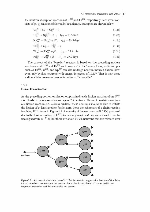
atom leads to the release of an average of 2.5 neutrons. Hence, to sustain a continu-ous fission reaction (i.e., a chain reaction), these neutrons should be able to initiatethe fission of at least another fissile atom. Note the schematic of a chain reactioninvolving U235 atoms in Figure 1.1. A majority of the neutrons (�99.25%) produceddue to the fission reaction of U235, known as prompt neutrons, are released instanta-neously (within 10�14 s). But there are about 0.75% neutrons that are released over
Figure 1.1 A schematic chain reaction of U235 fissile atoms in progress (for the sake of simplicity,it is assumed that two neutrons are released due to the fission of one U235 atom and fissionfragments created in each fission are also not shown).
1.5 Interactions of Neutrons with Matter j5

a longer period (over �20 s) and these neutrons are called delayed neutrons. Thesedelayed neutrons play a very important role in controlling the fission chainreaction.There is always a competition for neutrons between various processes,
namely, (i) fission reaction of fissile atom nuclei, (ii) nonfission capture ofneutrons by uranium and other reactions, (iii) nonfission capture of neutronsby other components in the reactor core, and (iv) leakage of neutrons from thecore. The reaction can be termed as a chain reaction when the number of neu-trons consumed in the processes (ii)–(iv) is at least equal to or less than thatconsumed in the process (i). Thus, neutron economy plays a very important rolein the design of a nuclear reactor. The need for a favorable neutron economynecessitates certain conditions to be met by a chain reacting system. For agiven geometry, there is a certain minimum size of a chain reacting system,called the critical size (in terms of volume), for which the production of neu-trons by fission just balances the loss of neutrons by leakage and so on, andthe chain reaction can be sustained independently. The mass corresponding tothe critical size is called critical mass. Dependent on the relative generation offission neutrons and their loss, the reactor is said to be in different stages:subcritical (neutron loss more than the production), critical (balance betweenthe neutron production and loss, k¼ 1), or supercritical (the neutron produc-tion is more than the loss, k> 1). The multiplication factor k is often used toexpress the criticality condition of a reactor. This factor is basically the netnumber of neutrons per initial neutron.
1.6Definition of Neutron Flux and Fluence
The concept of neutron flux is very similar to heat flux or electromagnetic flux.Neutron flux (w) is simply defined as the density of neutrons n (i.e., number ofneutrons per unit volume) multiplied by the velocity of neutrons v. Hence, nv rep-resents the neutron flux, which is the number of neutrons passing through a unitcross-sectional area per second perpendicular to the neutron beam direction. How-ever, sometimes this is called current if we consider that neutrons moving in onedirection only. Neutron flux, in general terms, should take into account all the neu-trons moving in all directions and be defined as the number of neutrons crossing asphere of unit projected area per second. Total neutron flux (w) is expressed by thefollowing integral:
w ¼Z 1
0wðEiÞdEi; ð1:4Þ
where w(Ei)dEi is the flux of neutrons with energies between Ei and Eiþ dEi.The term “nvt” represents the neutron fluence, that is, neutrons per unit cross-
sectional area over a specified period of time (here t). Thus, the units of neutronflux and fluence are n cm�2 s�1 and n cm�2, respectively.
6j 1 Overview of Nuclear Reactor Systems and Fundamentals
1.7Neutron Cross Section
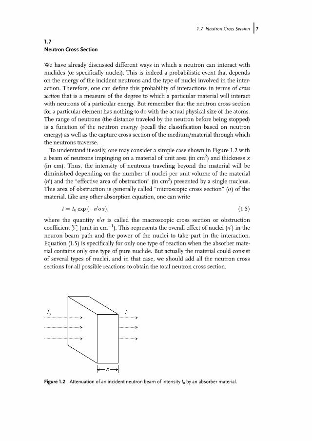
We have already discussed different ways in which a neutron can interact withnuclides (or specifically nuclei). This is indeed a probabilistic event that dependson the energy of the incident neutrons and the type of nuclei involved in the inter-action. Therefore, one can define this probability of interactions in terms of crosssection that is a measure of the degree to which a particular material will interactwith neutrons of a particular energy. But remember that the neutron cross sectionfor a particular element has nothing to do with the actual physical size of the atoms.The range of neutrons (the distance traveled by the neutron before being stopped)is a function of the neutron energy (recall the classification based on neutronenergy) as well as the capture cross section of the medium/material through whichthe neutrons traverse.To understand it easily, one may consider a simple case shown in Figure 1.2 with
a beam of neutrons impinging on a material of unit area (in cm2) and thickness x(in cm). Thus, the intensity of neutrons traveling beyond the material will bediminished depending on the number of nuclei per unit volume of the material(n0) and the “effective area of obstruction” (in cm2) presented by a single nucleus.This area of obstruction is generally called “microscopic cross section” (s) of thematerial. Like any other absorption equation, one can write
I ¼ I0 exp ð�n0sxÞ; ð1:5Þwhere the quantity n0s is called the macroscopic cross section or obstructioncoefficient
P(unit in cm�1). This represents the overall effect of nuclei (n0) in the
neuron beam path and the power of the nuclei to take part in the interaction.Equation (1.5) is specifically for only one type of reaction when the absorber mate-rial contains only one type of pure nuclide. But actually the material could consistof several types of nuclei, and in that case, we should add all the neutron crosssections for all possible reactions to obtain the total neutron cross section.
Figure 1.2 Attenuation of an incident neutron beam of intensity I0 by an absorber material.
1.7 Neutron Cross Section j7

From Eq. (1.5), a half-value thickness (x1/2) for neutron beam attenuation can bederived using the following relation:
x1=2 ¼ 0:693=ðn0 � sÞ: ð1:6Þ
The values of neutron microscopic cross section (s) are typically between 10�22
and 10�26 cm2, leading to the development of a convenient unit called barn(1 barn¼ 10�24 cm2).Note: Macroscopic neutron cross section (
P) can be calculated with the knowl-
edge of n0 that can be calculated from the following relation:
n0 ¼ ðr=MÞ � ð6:023� 1023Þ; ð1:7Þ
where r is the density (g cm�3) andM is the atomic weight of the element.
Thus;X
¼ ðr=MÞ � ð6:023� 1023Þs: ð1:8Þ
In order of increasing cross section for absorption of thermal neutrons, variousmetals can be classified as follows (normalized to Be):
Be 1;Mg 7;Zr 20;Al 24;Nb 122;Mo 278;Fe 281;Cr 322;Cu 410; and Ni 512
We will see in later chapters that neutron capture cross section has a significantrole to play in the selection of reactor materials coupled with other considerations.See Table 1.1 for some representative values of neutron capture cross sections forseveral important nuclides.Most nuclides exhibit both the 1/v (v¼ velocity of neutron) dependence of neu-
tron cross section and the resonance effects over the entire possible neutron energyspectrum. We should not forget that the neutron cross sections heavily depend onthe type of reactions they take part in, such as alpha particle producing reaction(sa), fission reactions (sf), neutron capture cross sections (sc), and so on. As dis-cussed above, the total cross section (st) is a linear summation of all neutronicreactions possible at the specific neutron energy level.
Table 1.1 Neutron cross sections (in barn) for capture of thermalneutrons (i.e., of average kinetic energy 0.025 eV) of a few nuclides.
Nuclide Neutron cross section (b)
11H 0.33221H 0.00052126C 0.003523892U 2.723592U 586
8j 1 Overview of Nuclear Reactor Systems and Fundamentals

The inverse proportionality of total neutron cross section in elemental boronas a function of neutron energy is shown in Figure 1.3. However, this is notalways the case. Many nuclides show abrupt increases in neutron cross sectionat certain narrow energy ranges due to resonance effects, which happens whenthe energy of the incident neutron corresponds to the quantum state of theexcited compound nucleus. An example of such a situation for Mn-55 isshown in Figure 1.4.
Figure 1.3 Variation of total cross section of elemental boron as a function of neutron energy.
Figure 1.4 Total cross section curve for Mn-55 over the neutron energy range of 0.01 eV–10 keV.(From M.F.L' Annunziata, Handbook of Radioactivity Analysis, Academic Press, New York, 1998;with permission.)
1.7 Neutron Cross Section j9
1.7.1Reactor Flux Spectrum
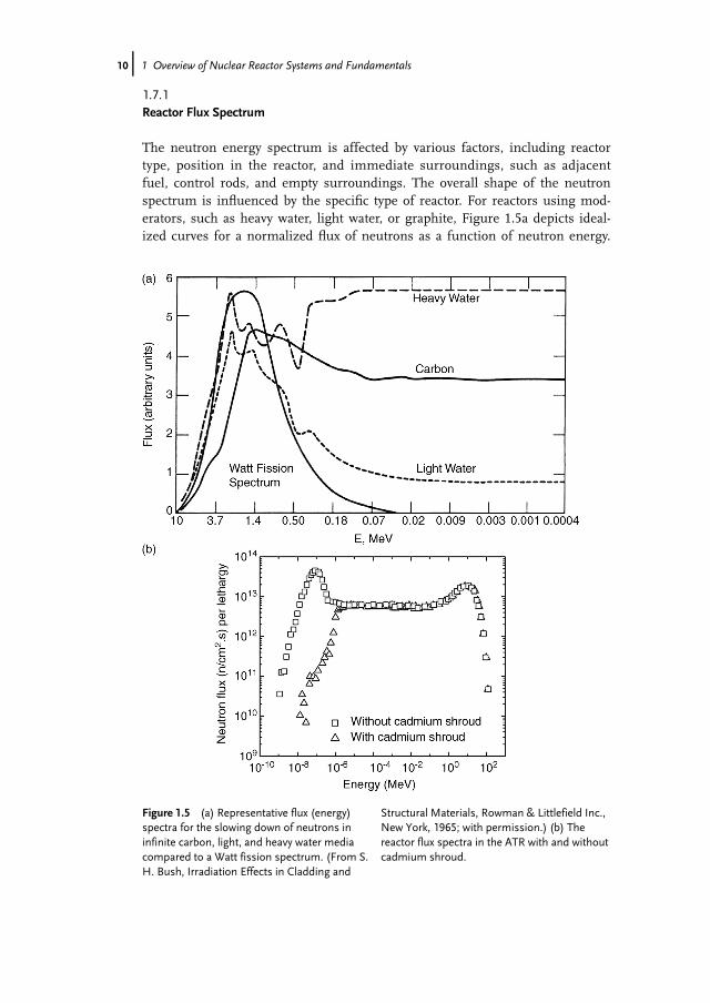
The neutron energy spectrum is affected by various factors, including reactortype, position in the reactor, and immediate surroundings, such as adjacentfuel, control rods, and empty surroundings. The overall shape of the neutronspectrum is influenced by the specific type of reactor. For reactors using mod-erators, such as heavy water, light water, or graphite, Figure 1.5a depicts ideal-ized curves for a normalized flux of neutrons as a function of neutron energy.
Figure 1.5 (a) Representative flux (energy)spectra for the slowing down of neutrons ininfinite carbon, light, and heavy water mediacompared to a Watt fission spectrum. (From S.H. Bush, Irradiation Effects in Cladding and
Structural Materials, Rowman & Littlefield Inc.,New York, 1965; with permission.) (b) Thereactor flux spectra in the ATR with and withoutcadmium shroud.
10j 1 Overview of Nuclear Reactor Systems and Fundamentals

The neutron fission spectrum calculated by Watt is also superimposed on thegraph for comparison. Convenient techniques such as assuming monoener-getic neutron flux and the arbitrary selection of neutron flux cutoff level(>1MeV) are mostly general approximations. Remember that most neutronfluxes cited at irradiation damage studies are expressed in terms of >1MeV.Figure 1.5b depicts the two flux spectra obtained from the Advanced TestReactor (ATR). One spectrum is without the use of cadmium shroud andanother one is with the cadmium shroud (of �1.14mm thickness). It is clearthat fast (hard) spectrum is achieved with the use of cadmium shroud (i.e.,irradiation jig wrapped into cadmium foil) due to its absorption of thermalneutrons, but not fast ones. Dosimetric experiments followed by calculationscan generate the flux spectrum for a specific position in the reactor.
1.8Types of Reactors
Even though a nuclear reactor can be defined in different ways, almost allreactors except fusion reactor (commercially nonexistent) can be defined asfollows: “A nuclear reactor is a device, designed to produce and sustain a longterm, controlled fission chain reaction, and made with carefully selected andstrategically placed collection of various materials.” The classification ofreactors vary and are generally based on the following: type of fission reaction(thermal, epithermal, and fast reactors), purpose of the reactor (power reactors,research reactors, and test reactors), type of the coolant present (such aslight/heavy water reactors, gas-cooled reactors, and liquid metal-cooledreactors), type of core construction (cubical, cylindrical, octagonal, and spheri-cal reactors), and so forth.
1.8.1A Simple Reactor Design
Almost all the reactors in the United States and a majority in the world arethermal reactors wherein thermal neutrons cause the bulk of the fissionreactions. If one starts to think about designing a prototype reactor, the severaldesign elements need to be flawlessly integrated. Figure 1.6 shows such a sche-matic for a primitive thermal reactor. The tubes containing fuels are generallymade of metallic alloys (also known as fuel cladding). The radioactive fuels(such as uranium) could be in metallic, alloy, or ceramic forms. The fuel clad-ding serves many purposes: it provides mechanical support to the fuel, keepsthe fission products from leaving the fuel element, and protects the fuels fromcorrosion from the coolant. The fuel elements are arranged in a distinct regularpattern (square, hexagon, etc., dictated by neutronics and other factors) with themoderator. Moderator slows down the neutron to sustain the fission reactionwith thermal neutrons. The fuel–moderator assembly is surrounded by a
1.8 Types of Reactors j11

reflector. The purpose of a reflector is to direct all neutrons generated towardthe core so that neutron leakage can be controlled, thus improving the neutroneconomy. On the outside, the reactor is lined by shielding materials that absorbneutrons and gamma rays that escape the core and reduce the radiation inten-sity to a tolerable level so that people near the reactor are not exposed to theseradiations. The control rod (usually an assembly) helps control the chainreaction by absorbing neutrons, maintaining the steady state of operation.Hence, the control materials are neutron-absorbing materials (boron, hafnium,and so forth), and are generally fabricated in the form of rods (in some cases,plates). A reactor is typically equipped with two types of control rods – regulat-ing rods for routine control reasons and safety rods (to permit shutdown in thecase of emergency). Even though coolant is not shown in Figure 1.6, it is animportant component of a reactor. As a huge amount of heat is generated inthe fuel elements, the heat needs to be removed continuously in an efficientmanner in order to maintain a safe, steady-state reactor operation. This meansan efficient coolant is needed. The coolant can be a gas or liquid (such as lightor heavy water, carbon dioxide, liquid metals, and molten salts). However, it isimportant to remember that the presence of any coolant tends to adverselyaffect the neutron economy. Hence, the balance between the reduction in theneutron economy and the efficiency of heat removal needs to be carefullyconsidered.
1.8.2Examples of Nuclear Reactors
A good point to start the discussion on various examples of nuclear reactors isto understand the evolution of nuclear power over the past six to seven
Control rod
Fuel element
Moderator
Reflector
Shield
Figure 1.6 A schematic of a simple reactor design. (adapted from C.O. Smith, Nuclear ReactorMaterials, Addison-Wesley, Reading, MA, 1967)
12j 1 Overview of Nuclear Reactor Systems and Fundamentals

decades. As shown in Figure 1.7, there are different generations of reactors.Thus, a chronological approach has been taken to start an overview of variousnuclear power reactors. However, it is, by no means, exhaustive account. Thefirst nuclear reactor known as Chicago Pile 1 (CP-1) was built during the hey-days of the World War II (criticality was achieved on December 2, 1942) at theUniversity of Chicago, Chicago, IL. It was designed and built by a team led byEnrico Fermi. This reactor was a thermal reactor with graphite moderators andnatural uranium dioxide fuel. No coolant or shielding was used. The reactorcould produce only �200W of heat. However, the primary aim of the reactorwas to demonstrate the occurrence of the fission chain reaction. It was dis-mantled in February 1943, and CP-2 reactor was installed at the ArgonneNational Laboratory based on the experience gained with CP-1.
1.8.2.1 Generation-I ReactorsGeneration-I reactors were built in the initial period of nuclear power expan-sion and generally had primitive design features. Most of these reactors haveeither been shut down or will be soon done so. Examples of such reactors areMagnox reactor (Calder Hall reactor in the United Kingdom) and first com-mercial power reactor at Shippingport in 1957 (in the state of Pennsylvania inthe United States).
Magnox ReactorThis is a notable Generation-I gas-cooled reactor. Early breed of this reactor wasused for the purpose of plutonium production (for atomic weapons) as well as elec-tricity generation. Figure 1.8a shows a cross section of a typical Magnox reactor. The
Figure 1.7 Nuclear power evolution in the world. Courtesy: The US Department of Energy Gen-IVInitiative.
1.8 Types of Reactors j13

Calder Hall station in the United Kingdom was a Magnox type of reactor startingsuccessful operation in 1956. Following that, several of these reactors were builtand operated in the United Kingdom and a few elsewhere (e.g., Italy, France, andJapan). Generally, Magnox reactors were graphite moderated, and used the naturaluranium as fuel clad in thin cylindrical tubes of a magnesium alloy (Magnox comesfrom the name of the magnesium-based alloy with a small amount of aluminumand other minor elements, magnesium nonoxidizing, for example, Mg–0.8Al–0.005Be) and carbon dioxide (CO2) as coolant (heat transfer medium). Magnesium-based alloy was chosen since Mg has a very low thermal neutron capture cross sec-tion (0.059 b; lower than Zr or Al). The fuel elements were impact extruded withthe integral cooling fins or machined from finned extrusions (Figure 1.8b). Also,
Figure 1.8 (a) A schematic of a Magnox reactor. (b) A part of the magnesium alloy fuel can of aBritish Magnox reactor. Courtesy: Light Alloys by Ian Polmear.
14j 1 Overview of Nuclear Reactor Systems and Fundamentals

the alloy was resistant to creep and corrosion from CO2 atmosphere in the operat-ing temperature range, and contrary to Al, the alloy did not react with the uraniumfuel. The addition of Al in the alloy provided solid solution strengthening, while thepresence of minor amounts of Be helped improve the oxidation resistance. CO2
was circulated under pressure through the reactor core and sent to the steam gener-ator to produce steam that is then passed through a turbo generator system gener-ating electricity. These reactors could sustain lower temperatures (maximumcoolant temperature of 345 �C) and, thus, has a limited plant efficiency and powercapacity. This was mainly out of the concern of the possible reaction of CO2 withgraphite at higher temperatures and the lower melting point of uranium fuel(1132 �C). Another problem was that the spent fuel from these reactors could notbe safely stored under water because of its chemical reactivity in the presence ofwater. Thus, the spent fuels needed to be reprocessed immediately after taking outof the reactor and expensive handling of equipment was required. Only two Mag-nox reactors still operating in the United Kingdom are scheduled to be decommis-sioned soon. Magnox reactors were followed by an improved version of gas-cooledreactor known as Advanced Gas-Cooled Reactor (AGR) operating at higher temper-atures and thus improving the plant efficiency. The magnesium fuel element wasreplaced by stainless steels.
1.8.2.2 Generation-II ReactorsMost of the commercial nuclear power plants operating today are of Genera-tion-II type. Also, the reactors employed in naval vessels (such as aircraft carri-ers and submarines) and many research/test reactors are of this type. TheGeneration-II reactors incorporated improved design and safety features andproductivity over Generation-I reactors. In the Western Hemisphere, a majorityof commercial nuclear power plants have light water reactor (LWR), both pres-surized water reactor (PWR) and boiling water reactor (BWR). It is importantto remember that LWRs were also built as Generation-I reactors (such as Ship-pingport facility with 60 MWe power capacity), however most of them are nolonger in operation. Another variety is the CANDU (Canadian Deuterium Ura-nium) reactor, which is basically a pressurized heavy water reactor (PHWR).There are a few different versions of pressurized water reactors (e.g., RBMKtype) in Russia and former Soviet-block countries, but discussion on thosereactors is outside the scope of this book.
Light Water ReactorsAs the name implies, LWRs use light water as the coolant and the moderator, andin many cases as the reflector material. These are typical thermal reactors as theyutilize thermalized neutrons to cause nuclear fission reaction of the U235 atoms.The thermal efficiency of these reactors hover around 30%. Two main types ofLWR are PWR and BWR. These two types are created mainly because of the differ-ence in approaches of the steam generating process (good quality steam should notcontain more than 0.2% of condensed water). LWRs have routinely been designedwith 1000MWe capacity.
1.8 Types of Reactors j15

Pressurized Water Reactor PWRs were designed and implemented commerciallymuch sooner than the BWRs due to the earlier notion that the pressurized liquidwater would somehow be much safer to handle than the steam in the reactor coreand would add to the stability of the core during the operation. That is why the firstcommercial reactor in Shippingport was a PWR. PWRs are designed and installedby companies such as Westinghouse and Areva.A schematic design of a typical PWR plant is shown in Figure 1.9a. A PWR plant
consists of two separate light water (coolant) loops, primary and secondary. ThePWR core is located inside a reactor pressure vessel (RPV) made of a low-alloy fer-ritic steel (SA533 Gr. B) shell (typical dimensions: outside diameter �5m, height�12m, and wall thickness 30 cm), which is internally lined by a reactor cladding of308-type stainless steel or Inconel 617 to provide adequate corrosion resistanceagainst coolant in contact with the RPV. The PWR primary loop works at an averagepressure of 15–16MPa with the help of a set of pressurizers so that the water doesnot boil even at temperatures of 320–350 �C. The PWR core contains an array offuel elements with stacks of a slightly enriched (2.5–4%) UO2 fuel pellets clad inZircaloy-4 alloy (new alloy is Zirlo or M5). Individual cladding tubes are generallyabout �10mm in outer diameter and �0.7mm in thickness. The fuel claddingtube stacked with fuel pellets inside and sealed from outside is called a fuel rod orfuel pin. About 200 of such fuel rods are bundled together to form a fuel element.Then, about 180 of such fuel elements are grouped together to form an array tocreate the reactor core of various shapes – square, cylindrical, hexagonal, and so on(Figure 1.9b). The reactor core is mounted on a core-support structure inside theRPV. Depending on the specific design, the above-mentioned dimensions of thevarious reactors may vary.The control rod used is typically an Ag–In–Cd alloy or a B4C compound,
which is used for rapid control (start-up or shutdown). Boric acid is also addedto the primary loop water to control both the water chemistry acting as “poi-son” and the long-term reactivity changes. This primary loop water is trans-ported to the steam generator where the heat is transferred to the secondaryloop system forming steam. The steam generator is basically a heat exchangercontaining thousands of tubes made from a nickel-bearing alloy (Incoloy 800)or nickel-based superalloy (e.g., Inconel 600) supported by carbon steel plates(SA515 Gr.60).
Boiling Water Reactor BWR design embodies a direct cycle system of cooling, thatis, only one water loop, and hence no steam generator (Figure 1.10a). Earlyboiling water experiments (BORAX I, II, III, etc.) and development of experi-mental boiling water reactor (EBWR) at the Argonne National Laboratory werethe basis of the future commercial BWR power plants. Dresden Power Station(200MWe), located at the south of Chicago, IL, was a BWR power plant thatstarted operating in 1960. It is of note that this was a Generation-I BWRreactor. However, most BWRs operating today are of Generation-II type andmost significant features are discussed below. The reactors (Fukushima Daii-chi) that underwent core melting following the unprecedented earthquake andtsunami in Japan during 2011 were all of BWR type.
16j 1 Overview of Nuclear Reactor Systems and Fundamentals
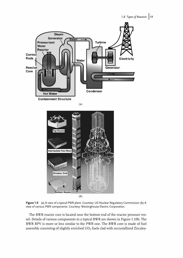
The BWR reactor core is located near the bottom end of the reactor pressure ves-sel. Details of various components in a typical BWR are shown in Figure 1.10b. TheBWR RPV is more or less similar to the PWR one. The BWR core is made of fuelassembly consisting of slightly enriched UO2 fuels clad with recrystallized Zircaloy-
Figure 1.9 (a) A view of a typical PWR plant. Courtesy: US Nuclear Regulatory Commission (b) Aview of various PWR components. Courtesy: Westinghouse Electric Corporation.
1.8 Types of Reactors j17
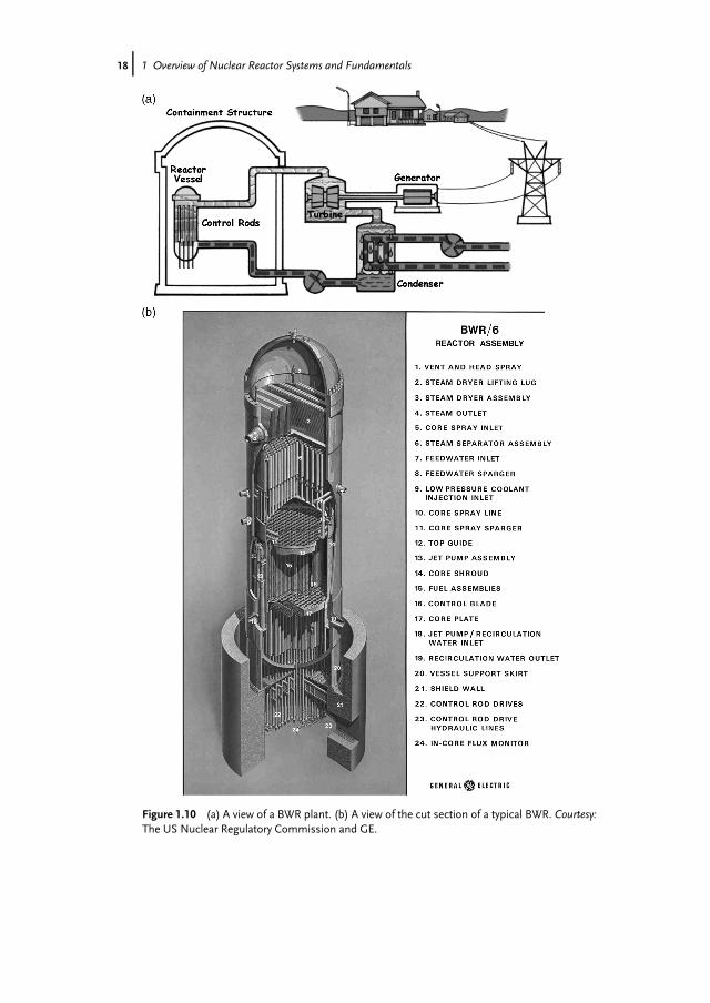
Figure 1.10 (a) A view of a BWR plant. (b) A view of the cut section of a typical BWR. Courtesy:The US Nuclear Regulatory Commission and GE.
18j 1 Overview of Nuclear Reactor Systems and Fundamentals

2 cladding tubes (about 12.5mm in outer diameter). For a BWR core of 8� 8 type,each fuel assembly contains about 62 fuel rods and 2 water rods, which are sealedin a Zircaloy-2 channel box. The control material is in the shape of blades arrangedthrough the fuel assembly in the form of a cruciform and is generally made of B4Cdispersed in 304-type stainless steel matrix or hafnium, or a combination of both.Water is passed through the reactor core producing high-quality steam and dried atthe top of the reactor vessel. The BWR operates at a pressure of about 7MPa andthe normal steam temperature is 290–330 �C.
Note
Tables 1.2 and 1.3 contain relevant information on PWRs and various types ofBWRs.
Table 1.2 PWR versus BWR.
PWR BWR
Principle of steam generationRPV pressure �15MPa RPV pressure�7MPaRPV temperature �326 �C RPV temperature �290 �CSteam generated in steam generator (viasecondary loop)
Steam generated in RPV (withseparator and dryer)
No bulk boiling in RPV Bulk boiling allowed in RPVMajor componentsRPV RPV with separator and dryerTwo–four steam generators No steam generatorOne pressurizer No pressurizerTop entry control rod clusters Bottom entry control rod drivesZircaloy-4 fuel cladding tubes Zircaloy-2 fuel cladding tubes
Table 1.3 Operating parameters and design features of BWRs.
Parameter/feature BWR (Browns Ferry 3) ABWR ESBWRa)
Power (MWt/MWe) 3293/1098 3926/1350 4500/1590Vessel height/diameter (m) 21.9/6.4 21.7/7.1 27.6/7.1Fuel bundles (number) 764 872 1132Active fuel height (m) 3.7 3.7 3.0Recirculation pumps (number) 2 (Large) 10 ZeroNumber of control drive rods 185 205 269Safety diesel generator 2 3 ZeroSafety system pumps 9 18 ZeroSafety building volume 120 180 135
Courtesy: GE Global Research.a) ESBWR – economic simplified boiling water reactor – of Generation-IIIþ category, developed by
the GE.
1.8 Types of Reactors j19

Pressurized Heavy Water Reactor The PHWR reactors were mainly developed by apartnership between the Atomic Energy of Canada Limited (AECL) and Hydro-Electric Power Commission of Ontario in 1960s. The reactors were of Generation-II type. Notably, these reactors are also called CANDU reactors (Figure 1.11a). Theyare so named because they use heavy water (deuterium oxide) as the moderator andnatural uranium as the fuel. These reactors are located mainly in Canada, India,China, and few other countries. The CANDU reactor design does not require areactor pressure vessel as in LWRs, and hence not a single CANDU reactor oper-ates in the United States since the nuclear safety regulations of the US NuclearRegulatory Commission specifically call for an RPV in a compliant reactor design.
Figure 1.11 (a) A simplified schematic view of a CANDU reactor. Courtesy: CanadianNuclear Association. (b) The configuration of fuel bundles in the fuel channel. Courtesy:www.cameco.com.
20j 1 Overview of Nuclear Reactor Systems and Fundamentals

Unlike LWRs, the natural uranium (0.7% U235) oxide fuel clad in zirconiumalloy tubes (known as pressure tubes, made of Zr–2.5Nb) is used in thisreactor. These hundreds of pressure tubes are kept inside a calandria shellmade of an austenitic stainless steel and reinforced by outer stiffening rings.The shell also keeps channels for the pressurized coolant (hot heavy water orlight water) and moderator (heavy water). If light water is used to moderatethe neutrons, it would adversely affect the neutron economy due to the absorp-tion of neutrons. That is why cold heavy water is used as the moderator. Thepressure tubes along with moderator and cooling tubes are arranged in a hori-zontal fashion (not vertical as in LWRs) and the fuels can be replaced andreloaded without shutting down the whole reactor. Note the fuel and associatedstructural configuration in Figure 1.11b. The pressurized coolant stays typicallyat about 290 �C. This reactor system requires a steam generator to producesteam as does a conventional PWR. The control rods are dropped verticallyinto the fuel zones in case total shutdown or controlling of reactivity is neces-sary. Gadolinium nitrate is added in the moderator system that acts as asecondary shutdown system.
Liquid Metal Fast Breeder Reactor Liquid metal (generally sodium) is used inliquid metal fast breeder reactors (LMFBRs) to transport the heat generated inthe core. These reactors are called “breeder” because more new fuels are pro-duced than consumed during its operation. The reactor can convert fertilematerial (containing U238 and Th232) into fissile materials (Pu239 and U233),respectively. The concept of this reactor type is very practical from the fuelutilization viewpoint. The natural uranium contains only about 0.7% of fissileU235. The majority of the natural uranium contains U238 isotope. Thesereactors are characterized by high power density (i.e., power per unit volume)due to the lack of a moderator (i.e., much more improved neutron economy).The reactor cores are typically small because of the high power densityrequirements. The temperature attained in this type of reactors is higher andthus leads to higher efficiency of electric power generation (�42% in LMFBRsversus �30% in LWRs). The use of Th232 in LMFBRs is particularly advanta-geous for countries like India that do not have a large deposit of uranium, buthas plenty of thorium. It should be noted that sodium used in this type ofreactor transfers heat to the steam generators. The system containing sodiumshould be leak-proof since sodium reacts with oxygen and water vapor veryfast. Furthermore, it becomes radioactive as the coolant passes through thereactor core. The whole primary coolant system should be put in the shieldedprotection to keep the operating personnel safe.The first prototype LMFBR reactor named EBR-I (Experimental Breeder Reactor)
was built at the present-day site of the Idaho National Laboratory near Idaho Falls,ID. This was the first reactor to demonstrate that the electricity can be generatedusing the nuclear energy. Also, it was the first “fast breeder” reactor. It usedsodium–potassium (NaK) as coolant. It started its operation in 1951, and wasdecommissioned by 1964. By this definition, it was a Generation-I fast reactor
1.8 Types of Reactors j21

design. Following the decommissioning of EBR-I, another fast breeder reactor(EBR-II) was installed and started operation in 1963. EBR-II (Figure 1.12) was oper-ated very successfully before it was shut down in 1994. The fuel used was a mixtureof 48–51% of U235, 45–48% U238, and the rest a mixture of fissium metals (Mo, Zr,Ru, etc.) and plutonium.
1.8.2.3 Generation-III and IIIþ ReactorsThe new reactors that are being built or will be built within a few years are of Gener-ation-III category. These are mainly advanced LWRs. Examples include advancedboiling water reactor (ABWR) and evolutionary or European power reactor (EPR). Inthe same line, Generation IIIþ category aims to provide reactor systems that havemuch improved designs and safety features, and much greater capacities. Notably,all these reactors are thermal in nature. No fast reactor is in the pipeline in thesecategories. An improved version of the US EPR1 is being designed and developedas a Generation IIIþ reactor by AREVA NP. It is a four-loop plant with a rated ther-mal power of 4590MWth. Figure 1.13a and b shows the details of a EPR power plant.The primary system design and main components are similar to those of PWRs
currently operating in the United States. However, the US EPR incorporates severalnew advancements in materials technology as well as new uses for existing materi-als. Some notable examples include M51 fuel cladding and the stainless steel heavyneutron reflector. Some details of these are discussed below:
a) Zircaloy-4 (Zr-4) has been used extensively for many years in PWR fuel claddingapplications. Zr-4 is a cold worked stress-relieved (CWSR) alloy with a zirconiumbase containing tin, iron, chromium, and oxygen. This offers good corrosionresistance and mechanical properties. AREVA NP has developed an advancedzirconium alloy for PWR fuel rod cladding and fuel assembly structural compo-nents, known as M51 (Zr-0.8–0.12Nb–0.09–0.13O). M51 makes high-burnupfuel cycles possible in the increasingly higher duty operating environments ofPWRs. Introduced commercially in the 1990s after a rigorous development pro-gram, M51 was a breakthrough in zirconium alloy development. This fullyrecrystallized, ternary Zr–Nb–O alloy produces improved in-reactor corrosion,
Figure 1.12 A view of EBR-II reactor.
22j 1 Overview of Nuclear Reactor Systems and Fundamentals

hydrogen, growth, and creep behaviors. The remarkably stable microstructureresponsible for these performance improvements is the result of carefully con-trolled ingot chemistry and product manufacturing parameters. M51 helps util-ities achieve significant fuel cycle cost savings and enhanced operating margins
Figure 1.13 (a) A layout of a US EPR1 power plant. (b) Main coolant line components in the USEPR1. Courtesy: Areva NP.
1.8 Types of Reactors j23

by allowing higher burnups and higher duty cycles. Excellent corrosion resist-ance and low irradiation growth allow higher burnups, extended fuel cycle opera-tion, and fuel assembly design modifications that enhance operating flexibility.The corrosion resistance of M51 allows operation in high pH environments,eliminating the risk of oxide spalling and helping to minimize dose rates. M51
has been proven to withstand severe operating conditions: high neutron flux,heat flux, and high operating temperatures. As of January 2007, over 1 576 000fuel rods in designs from 14� 14 (Figure 1.14) to 18� 18 matrices have beenirradiated in commercial PWRs to burnups exceeding 80 000MWdpermtU. Infuel rod cladding with hydrogen concentrations above the solubility limit, excesshydrogen precipitates as brittle hydrides, reducing the ability of the cladding tocope with pellet-to-clad mechanical interactions during reactivity insertion acci-dents. During a LOCA, ( Loss Of Coolant Accident) high hydrogen levels incre-ase the transport and solubility of oxygen at high temperatures, leading tosubstantial embrittlement of the cladding as it cools and the oxygen precipitates.M51 cladding absorbs approximately 85% less hydrogen than other Zr-4-basedalloys. As a result, M51 will not reach hydrogen levels sufficient enough to pre-cipitate hydrides and will not lead to excess oxygen absorption during a LOCA.
b) The space between the multicornered radial periphery of the reactor core andthe cylindrical core barrel is filled with an austenitic stainless steel structure,called the heavy reflector. The primary purpose of the heavy reflector is to reducefast neutron leakage and flatten the power distribution of the core, thus improv-ing the neutron utilization. It also serves to reduce the reactor vessel fluence(�1� 1019 n cm�2, E> 1MeV after 60 years). The reflector is inside the corebarrel above the lower core support plate. The reflector consists of stackedforged slabs (rings) positioned one above the other with keys, and axiallyrestrained by tie rods bolted to the lower core.
Figure 1.14 A 14 � 14 matrix fuel assembly made of M51 alloy. Courtesy: Areva NP.
24j 1 Overview of Nuclear Reactor Systems and Fundamentals

1.8.2.4 Generation-IV ReactorsGen-IV reactors are the futuristic reactors for which research and developmentefforts are currently in progress. These reactors will be more efficient, safer, longerlasting (60 years and beyond), proliferation-resistant, and economically viable com-pared to the present nuclear reactors. Six reactor designs were selected at the out-set. They are summarized in Table 1.4 including information on the type (fast orthermal spectrum) of the reactor, coolants, and approximate core outlet tempera-tures. Two reactor concepts, sodium fast reactor (SFR) – along with the advancedburner reactor (ABR) concept under the erstwhile Advanced Fuel Cycle InitiativeProgram) – and very high-temperature reactor (VHTR) under the Next GenerationNuclear Plant (NGNP) are of the highest priority in the United States (Figure 1.15aand b, respectively). VHTR is the reactor concept employed for the Next GenerationNuclear Plant program where the heat generated will cogenerate electricity andhydrogen.The demanding service conditions (higher neutron doses, exposure to higher
temperatures, and corrosive environments) that the structural components willexperience in these reactors would pose a significant challenge for the structuralmaterials selection and qualification efforts. Because of the stringent requirementsnoted above, the materials employed in today’s commercial reactors are not suitablefor use in Gen-IV reactors. For example, zirconium alloys (Zircaloy-2, Zircaloy-4,Zr-2.5Nb, M5) have been used routinely as fuel cladding and other reactor internalsin both light and heavy water reactors because of their low neutron capture crosssection and acceptable mechanical and corrosion resistance in high temperature
Table 1.4 A summary of Gen-IV reactor system designs.
Reactor system Priority/timeline Coolant Neutronspectrum
Core outlettemperature(�C)
Gas-cooled fastreactor (GFR)
Medium/long term Gas (e.g., He) Fast �850
Lead-cooledreactor (LFR)
Medium/long term Liquid metal(e.g., Pb, Pb–Bi)
Fast 550–800
Molten saltreactor (MSR)
Low/long term Molten salt(e.g., fluoridesalts)
Thermal 700–800
Sodium-cooledfast reactor (SFR)
High/mid term Liquid metal (Na) Fast �550
Very high-temperaturereactor (VHTR)
High/mid term Gas (e.g., He),CO2
Thermal > 900
Supercriticalwater-cooledreactor (SCWR)
Medium/long term Water Thermal/fast 280–620
1.8 Types of Reactors j25

Figure 1.15 Schematics of (a) a sodium fast reactor and (b) a very high-temperature reactor.(Courtesy: US Department of Energy Gen-IV Initiative)
26j 1 Overview of Nuclear Reactor Systems and Fundamentals
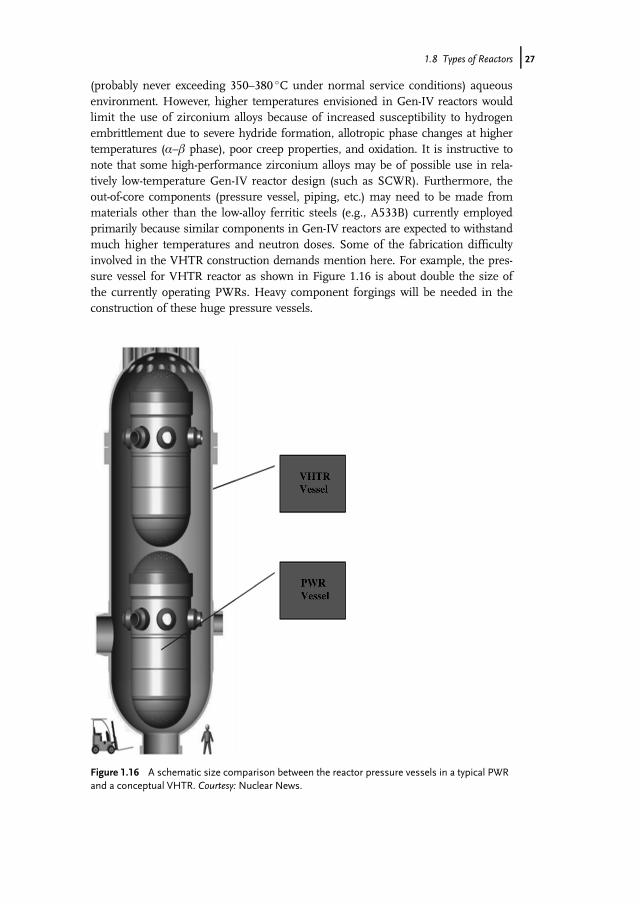
(probably never exceeding 350–380 �C under normal service conditions) aqueousenvironment. However, higher temperatures envisioned in Gen-IV reactors wouldlimit the use of zirconium alloys because of increased susceptibility to hydrogenembrittlement due to severe hydride formation, allotropic phase changes at highertemperatures (a–b phase), poor creep properties, and oxidation. It is instructive tonote that some high-performance zirconium alloys may be of possible use in rela-tively low-temperature Gen-IV reactor design (such as SCWR). Furthermore, theout-of-core components (pressure vessel, piping, etc.) may need to be made frommaterials other than the low-alloy ferritic steels (e.g., A533B) currently employedprimarily because similar components in Gen-IV reactors are expected to withstandmuch higher temperatures and neutron doses. Some of the fabrication difficultyinvolved in the VHTR construction demands mention here. For example, the pres-sure vessel for VHTR reactor as shown in Figure 1.16 is about double the size ofthe currently operating PWRs. Heavy component forgings will be needed in theconstruction of these huge pressure vessels.
Figure 1.16 A schematic size comparison between the reactor pressure vessels in a typical PWRand a conceptual VHTR. Courtesy: Nuclear News.
1.8 Types of Reactors j27

Test Reactors
So far we have discussed the past, current, and future nuclear reactors in detail.Now let us discuss about a test reactor. One of the well-known test reactors inthe United States is the Advanced Test Reactor located at the Idaho NationalLaboratory near Idaho Falls, ID. ATR is a flagship reactor that serves the USDepartment of Energy, Naval Nuclear Propulsion Program, and different othergovernmental and commercial entities. It also acts as a user facility that theuniversity-led teams can use to irradiate materials and perform postirradiationexamination (PIE) upon going through a competitive proposal process. ATRstarted its operation in 1967 and is being operated continuously since thenwith 250þ days of operation in an average year. A view section of the ATR isshown in Figure 1.17.ATR is a pressurized, light water cooled and moderated, 250 MWth reactor
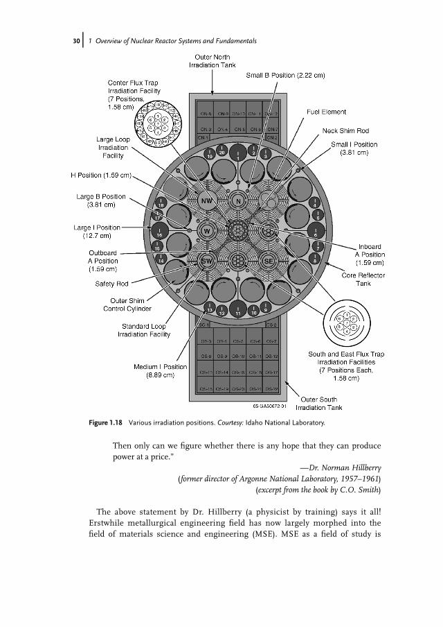
with beryllium reflectors and hafnium control drums. The metallic fuel (U or U–Mo) is in the plate morphology clad in an aluminum alloy. There are 40 fuelassemblies in the reactor core; each core contains 19 fuel plates. At 250 MW,maximum thermal neutron flux is �1015 n cm�2 s�1, and the maximum fast neu-tron flux could reach 5� 1014 n cm�2 s�1. Thus, ATR can be used to study theradiation damage under the fast neutron spectrum. The ATR has 77 irradiationpositions (4 flux traps, 5 in-pile tubes, and 68 in-reflector) (for details, seeFigure 1.18). The reactor pressure vessel is made of stainless steel, and is3.65 m in diameter and �10.67m in height. Table 1.5 lists some of the differ-ences between ATR and a typical PWR.ATR even though used for neutron irradiation experiments is not a fast
reactor facility. Note that at present the United States does not have anyoperating/underconstruction fast reactor test facility (EBR-II and FFTF facili-ties were shut down during 1990s) as opposed to countries like France (Phe-nix), India (prototype fast breeder reactor (PFBR)), Japan (Joyo and Monju),Russia (BOR-60), and China (China experimental fast reactor (CEFR). Thelack of a fast reactor facility is a challenge for the US nuclear R&D commu-nity. The proposed Advanced Burner Test Reactor (ABTR), a sodium-cooledfast reactor, is still under the planning stage, and there is no further confir-mation of its installation yet.
1.9Materials Selection Criteria
“We physicists can dream up and work out all the details of power reactorsbased on dozens of combinations of the essentials, but it’s only a paperreactor until the metallurgist tells us whether it can be built and from what.
28j 1 Overview of Nuclear Reactor Systems and Fundamentals

Figure 1.17 A view section of the Advanced Test Reactor. Courtesy: Idaho National Laboratory.
Table 1.5 Comparison between ATR and a typical PWR.
Reactor Features ATR PWR
Power (MWth) 250 (maximum design) �3800Operating pressure (MPa per psig) �2.5/�355 �15.5/�2235Inlet temperature (�C) �52 �288Outlet temperature (�C) �71 �327Power density (kW per ft3) �28 300 �2800Fuel element shape Plate TubularFuel Enriched U235 3–4% Enriched U235
Fuel temperature (�C) �462 >538
1.9 Materials Selection Criteria j29
Then only can we figure whether there is any hope that they can producepower at a price.”
—Dr. Norman Hillberry(former director of Argonne National Laboratory, 1957–1961)
(excerpt from the book by C.O. Smith)
The above statement by Dr. Hillberry (a physicist by training) says it all!Erstwhile metallurgical engineering field has now largely morphed into thefield of materials science and engineering (MSE). MSE as a field of study is
Figure 1.18 Various irradiation positions. Courtesy: Idaho National Laboratory.
30j 1 Overview of Nuclear Reactor Systems and Fundamentals

based on a common theme of finding out the interlinkage between process-ing, structure, and properties in various types of materials. If the interlinkageis clearly understood and established, the performance of these materialsunder service conditions could be ensured. Hence, the materials selectionprocess in any structure design is a very important step. It is very common toencounter various tradeoffs during the materials selection process for a givenapplication, and most times compromise is called for. Moreover, a nuclearreactor design entails complex procedures in itself given the multiple chal-lenges. Different components of a reactor may require different types ofmaterials. This is mostly done with the help of engineering expertise (experi-ence and judgment).There could be two broader types of materials selection considerations – gen-
eral and special. General considerations involve factors such as mechanicalstrength, ductility, toughness, dimensional stability, fabricability, cost and avail-ability, heat transfer properties, and so on. General properties come from thegeneral engineering considerations as they would be applicable in most engi-neering designs. On the other hand, special properties are considered solelybecause the materials are to be used in a nuclear reactor. These include prop-erties like the neutron absorbing characteristics, susceptibility to inducedradioactivity, radiation damage resistance, and ease of reprocessing of materi-als. Each of the material characteristics is evaluated following standard (some-times nonconventional) testing procedures. The knowledge of serviceconditions and broader goals of the future reactor is a must for a successfulmaterials selection process. This information may come from utilizing predic-tive capabilities (modeling and simulation tools) and/or known data/experien-ces from previous reactor design and operations, if available. Brief discussionson these properties have been made in the following sections. Some of theseproperties will be again elaborated in the subsequent chapters.
1.9.1General Considerations
1.9.1.1 General Mechanical PropertiesImportant general mechanical properties include tensile strength, ductility, andtoughness. The material should be strong enough to bear the loads of thestructure and also sustain any internal or external stresses generated duringservice. Also, the material should have enough ductility (a measure of percent-age elongation or reduction in area in standard tensile specimens) to avoid anycatastrophic failure. Usually, as a rule of thumb, a percentage elongation of 5%is considered a minimum requirement for a load-bearing engineering struc-ture. But one must admit that this often changes with the type of applicationat hand. In some cases, the materials should have sufficient ductility in orderto be formed into different components. Toughness is defined as the ability ofa material to absorb energy without failure, and that dictates how tough a
1.9 Materials Selection Criteria j31

material is for use. Generally, tensile strength and ductility combined isreferred to as toughness. However, generally impact tests and fracture tough-ness tests are conducted to evaluate toughness properties of materials. Allthese affect the mechanical integrity of the reactor components.
1.9.1.2 FabricabilityFabricability includes a host of characteristics such as formability, weldability,machinability, and so on. If fabricability issues are not dealt with during the firststage, it may cause problems at the later stages. In many cases, some parts of thenuclear power plant are to be built at the site (also called field fabrication) fromsmaller parts. If the materials do not have the requisite fabricability, it would not bepossible to use the material no matter what fantastic properties it may have!
1.9.1.3 Dimensional StabilityThe material should have adequate stability in properties. For example, manynuclear components would work at higher temperatures for extended period oftime. So, the creep deformation (i.e., time-dependent plastic deformation) maycause dimensional stability problems.One should also recognize that the microstructure of a material changes as a
function of temperature, time, and stresses. So, the effects of these factors onmicrostructure and the consequent effects on the properties need to be taken intoaccount carefully.
1.9.1.4 Corrosion ResistanceCorrosion is an electrochemical process that causes the surface of the metals/alloysdegrade over time in the presence of a chemical environment. Corrosion resistanceof materials used in nuclear components is important in many applications toensure that they serve as desired. The “cost of corrosion” can result in immediateproperty and life endangerment and increased downtime, leading to substantiallosses. Many nuclear components inside the reactor stay in close contact withreactor fluids (e.g., coolant in the form of liquid or gas). These effects get exacer-bated due to the presence of radiation fields.
1.9.1.5 DesignAlthough design does not generally fall under the purview of a materials engi-neer, he/she is in a unique position to figure out early whether the faultydesign would pose a problem. Designs leaving stress concentration sites (sharprecesses, keyholes, and the like) are typically unwarranted in load-bearingapplications since it may interfere with the capability of the component toserve properly. For example, fatigue properties are especially prone to the pres-ence of stress concentration sites.
1.9.1.6 Heat Transfer PropertiesAs we know from our fundamental physics classes, heat transfer modes are ofthree types – conduction, convection, and radiation. The first two processes are of
32j 1 Overview of Nuclear Reactor Systems and Fundamentals

importance in nuclear reactor materials selection. Most important example innuclear reactor is the choice of fuel and cladding materials. The safety and effi-ciency of the reactor depends on how efficiently the heat generated inside the fuelcan be removed. Hence, thermal conductivity is an important property. Otherwise,the fuel will melt such as in a “loss of coolant accident” (LOCA) scenario. Similarly,heat transfer properties are also important for various balance-of-plant features,such as heat exchangers, condensers, and other ancillary equipment (such as steamgenerator in a PWR system).
1.9.1.7 Availability and CostThis is the last but not the least general consideration in the materials selectionprocess. Availability and cost are the economic consideration that may trump tech-nical considerations. If a material is not available in the form or at an allowableprice, the prudent engineering decision would be to find an alternative materialwith similar properties or a different form of material or make changes in designto allow different characteristics. Cost-benefit analysis must be at the heart of thatprocess. In this regard, the fair question becomes, “If it were your money, wouldyou refuse to buy the item because it costs too much?”
1.9.2Special Considerations
1.9.2.1 Neutronic PropertiesNeutronic properties are of significant consideration in the design and develop-ment of nuclear reactors. As discussed earlier, the fission chain reaction requirescontinued supply of neutrons for it to proceed and that is why neutron economyplays an important role. Fuel cladding materials need to have a lower neutronabsorption cross section and that is why zirconium alloys are used in LWRs (seeAppendix 1.A). On the other hand, to control the chain reaction, the control materi-als should have high neutron absorption cross section. The same considerationwould also apply to shielding materials.
1.9.2.2 Susceptibility to Induced RadioactivityThe materials in the reactor can absorb fast/thermal neutrons and undergoreactions that may lead to the production of different radioactive isotopes ofthe constituent elements of the materials. These reactions can induce radio-activity as these isotopes would decay by emitting gamma rays, beta rays, andalpha rays of different energy levels. While selecting an alloy, we should beconcerned about the following factors: (a) quantity of the impurities/alloyingelements, (b) abundance of the isotopes and corresponding cross section, (c)half-life of the product nuclide, and (d) the nature of the radiation produced.If the produced isotope has a short half-life and emit radiation of low energy,it should not be a cause for great concern. However, if the isotope is long-livedand produces radiation of high energy, all precautions must be taken. For
1.9 Materials Selection Criteria j33
example, the main isotope of iron (Fe56) that accounts for almost 92% of thenatural iron forms a stable isotope (Fe57) upon absorbing neutrons. Theabsorption of neutrons in Fe54 and Fe58 yielding Fe55 (half-life: 2.9 years) andFe59 (half-life: 47 days) results in activation. However, the impurities or alloy-ing elements cause more induced radioactivity than iron itself. Generally, thetest samples irradiated in a reactor are not examined immediately after takingout from the reactor because they remain literally hot and continue to be hotdue to the decay heat produced by various reactions even if the fission chainreaction no longer occurs. The Fukushima Daiichi accident in Japan did showthe severity of the heat produced due to these decay reactions even after theemergency shutdown of the reactor, leading to very high temperatures (in theabsence of proper coolant) and eventually resulting in the cladding breach andperhaps some form of core melting.
Note
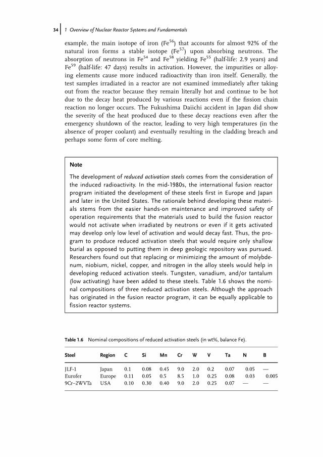
The development of reduced activation steels comes from the consideration ofthe induced radioactivity. In the mid-1980s, the international fusion reactorprogram initiated the development of these steels first in Europe and Japanand later in the United States. The rationale behind developing these materi-als stems from the easier hands-on maintenance and improved safety ofoperation requirements that the materials used to build the fusion reactorwould not activate when irradiated by neutrons or even if it gets activatedmay develop only low level of activation and would decay fast. Thus, the pro-gram to produce reduced activation steels that would require only shallowburial as opposed to putting them in deep geologic repository was pursued.Researchers found out that replacing or minimizing the amount of molybde-num, niobium, nickel, copper, and nitrogen in the alloy steels would help indeveloping reduced activation steels. Tungsten, vanadium, and/or tantalum(low activating) have been added to these steels. Table 1.6 shows the nomi-nal compositions of three reduced activation steels. Although the approachhas originated in the fusion reactor program, it can be equally applicable tofission reactor systems.
Table 1.6 Nominal compositions of reduced activation steels (in wt%, balance Fe).
Steel Region C Si Mn Cr W V Ta N B
JLF-1 Japan 0.1 0.08 0.45 9.0 2.0 0.2 0.07 0.05 —
Eurofer Europe 0.11 0.05 0.5 8.5 1.0 0.25 0.08 0.03 0.0059Cr–2WVTa USA 0.10 0.30 0.40 9.0 2.0 0.25 0.07 — —
34j 1 Overview of Nuclear Reactor Systems and Fundamentals
1.9.2.3 Radiation StabilityIn the subsequent chapters, we will see more detailed accounts of how energeticradiation plays a significant role in modifying the microstructure of the materialsinvolved. Radiation damage under the fast neutron flux involves atomic displace-ments (i.e., displacement damage) leading to the creation of a host of defects in thematerial. The effects of radiation can be diverse, including radiation hardening,radiation embrittlement, void swelling, irradiation creep, and so forth, with all hav-ing significant effects on the performance of the reactor components. Anotherinteresting effect of radiation is the radiolytic decomposition of coolant (e.g., watermolecule is radiolyzed into more active radicals) that may definitely affect the corro-sion behavior of the reactor components. Fission fragments also cause damage, butthey are mostly limited to the fuel. So, for selecting materials for a nuclear reactor,we must know the concomitant radiation effects on these materials. That is whymillions of dollars are spent to wage materials irradiation campaigns in testreactors followed by careful postirradiation examination to ascertain fitness-for-ser-vice quality of the materials to be used in nuclear reactors.
1.9.3Application of Materials Selection Criteria to Reactor Components
Here, we summarize the criteria for materials selection for different nuclearcomponents. Let us take the example of fuel cladding material for the LWR. Asnoted before, cladding materials are used to encapsulate the fuel and separate itfrom the coolant. The requirements for fuel cladding material are as follows: (a)low cross section for absorption of thermal neutrons, (b) higher melting point,adequate strength and ductility, (c) adequate thermal conductivity, (d) compati-bility with fuel, and (e) corrosion resistance to water. Following the first factor,we have discussed in Section 1.7 how different metals have different cross sec-tions for absorption of thermal neutrons. Although Be, Mg, and Al all havelower cross sections for absorption of thermal neutrons, other nonnuclear fac-tors become the impediment for their use in commercial power reactors. Eventhough Be has a high melting point (1278 �C), it is scarce, expensive, difficult tofabricate, and toxic. Mg has a low melting point (650 �C), is not strong at highertemperatures, and has poor resistance to hot water corrosion. Al has a low melt-ing point (660 �C) and poor high-temperature strength. Even though an Al-based alloy has been used as fuel cladding materials in reactors like ATR, andin the past a magnesium-based alloy was used in Magnox reactors, their useremains very limited. This leaves zirconium-based materials as the mainstay offuel cladding materials for LWRs. Zirconium has various favorable features: (a)relatively abundant, (b) not prohibitively expensive, (c) good corrosion resist-ance, (d) reasonable high-temperature strength, and (e) good fabricability. Someof the properties could be further improved through appropriate alloying. Moredetailed discussion on the development of zirconium alloys is included inAppendix 1.A at the end of the chapter.
1.9 Materials Selection Criteria j35

1.9.3.1 Structural/Fuel Cladding Materials
Major requirements Possible materials
Low neutron absorption Al, Be, Mg, and ZrStability under heat and radiation Stainless steelsMechanical strength Superalloys (Ni-based)Corrosion resistance Refractory metals (Mo, Nb, Ti, W, etc.)Good heat transfer properties
1.9.3.2 Moderators and Reflectors
Major requirements Possible materials
Low neutron absorption Water (H2O, D2O)Large energy loss by neutron per collision Beryllium (BeO)High neutron scattering Graphite (C)
1.9.3.3 Control Materials
Major requirements Possible materials
High neutron absorption BoronAdequate strength CadmiumLow mass (for rapid movement) HafniumCorrosion resistance HafniumStability under heat and radiation Rare earths (Gadolinium,
Gd; Europium, Eu)
1.9.3.4 Coolants
Major requirements Possible materials
Low neutron absorption Gases (air, hydrogen, helium,carbon dioxide, and water)
Good heat transfer properties Water (H2O and D2O)Low pumping power
(i.e., low melting point)Liquid metals (Na, Na��K, Bi)
Stability under heat and radiation Molten salts (��Cl, ��OH, ��F)Low induced radioactivity Organic liquidsNoncorrosiveness
36j 1 Overview of Nuclear Reactor Systems and Fundamentals

(Example:The world’s first nuclear power plant was EBR-1.It carried a coolant, an alloy of sodium (Na) and potassium (K), called Na��K
(“nack”).The following are the coolant characteristics:
� Stays liquid over a wide range of temperatures without boiling away.� Transfers heat very efficiently taking heat away from the reactor core and keeping
it cool.� Allows neutrons from the reactor core to collide with U-238 in the breeding blan-
ket and produce more fuels.)
1.9.3.5 Shielding Materials
Major requirements Possible materials
Capacity to slow down neutrons Light water (H2O)Absorption of gamma radiation Concrete, most control materials,
and metals (Fe, Pb, Bi, Ta, W,and Broal – a B and Al alloy)
Absorb neutrons
1.10Summary
In this introductory chapter, we first introduced nuclear energy and discussed itssignificance in the modern civilization. We also discussed some nuclear physicsfundamentals such as half-value thickness for neutron beam attenuation, nuclearcross sections, neutron flux and fluence, and other concepts. A detailed overview ofdifferent reactors is presented. The material selection criteria for nuclear compo-nents are also discussed.
Appendix 1.A
Zirconium-based alloys are commonly used in water reactors for cladding UO2,while Zircaloy-2 and Zircaloy-4 are used in BWRs and PWRs, respectively. The fol-lowing are the reasoning and historical development of these cladding materials:The fuel (UO2) is inserted in canning tubes that separate the radioactive fuel
from the coolant water. The requirements for cladding materials thus are as follows:
� Low cross section for absorption of thermal neutrons� Adequate strength and ductility� Compatibility with fuel
1.10 Summary j37
� Adequate thermal conductivity� Corrosion resistance to water
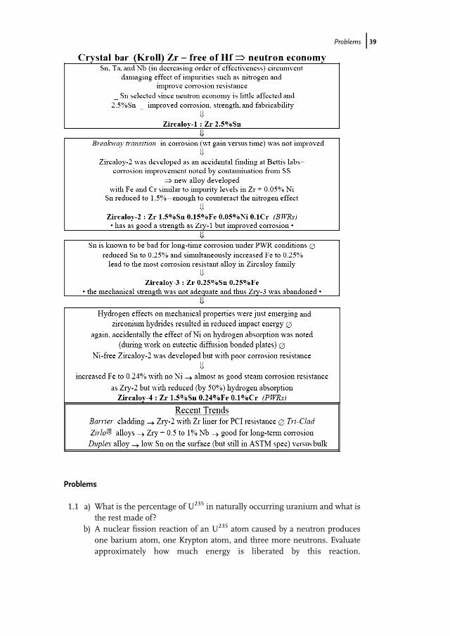
In order of increasing cross section for absorptionPth
a
n oof thermal neutrons,
the various metals can be classified [normalized to Be] as follows:
Relative to Be 1 7 20 24 122 278 281 322 410 512Be Mg Zr Al Nb Mo Fe Cr Cu Ni
Melting point f�Cg 1283 650 1845 660 2415 2625 1539 1890 1083 1455
Be: scarce, expensive, difficult to fabricate, and toxicMg: not strong at high temperatures and poor resistance to hot water corrosionAl: low melting point and poor high temperature strength
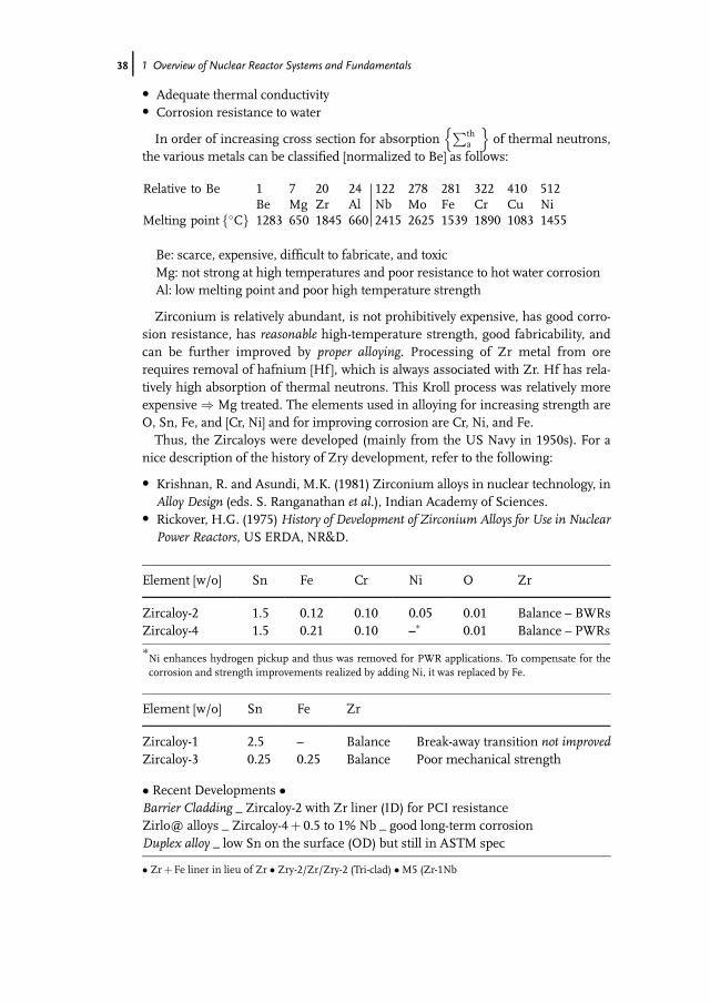
Zirconium is relatively abundant, is not prohibitively expensive, has good corro-sion resistance, has reasonable high-temperature strength, good fabricability, andcan be further improved by proper alloying. Processing of Zr metal from orerequires removal of hafnium [Hf], which is always associated with Zr. Hf has rela-tively high absorption of thermal neutrons. This Kroll process was relatively moreexpensive ) Mg treated. The elements used in alloying for increasing strength areO, Sn, Fe, and [Cr, Ni] and for improving corrosion are Cr, Ni, and Fe.Thus, the Zircaloys were developed (mainly from the US Navy in 1950s). For a
nice description of the history of Zry development, refer to the following:
� Krishnan, R. and Asundi, M.K. (1981) Zirconium alloys in nuclear technology, inAlloy Design (eds. S. Ranganathan et al.), Indian Academy of Sciences.
� Rickover, H.G. (1975)History of Development of Zirconium Alloys for Use in NuclearPower Reactors, US ERDA, NR&D.
Element [w/o] Sn Fe Cr Ni O Zr
Zircaloy-2 1.5 0.12 0.10 0.05 0.01 Balance – BWRsZircaloy-4 1.5 0.21 0.10 –� 0.01 Balance – PWRs
�Ni enhances hydrogen pickup and thus was removed for PWR applications. To compensate for thecorrosion and strength improvements realized by adding Ni, it was replaced by Fe.
Element [w/o] Sn Fe Zr
Zircaloy-1 2.5 – Balance Break-away transition not improvedZircaloy-3 0.25 0.25 Balance Poor mechanical strength
� Recent Developments �Barrier Cladding _ Zircaloy-2 with Zr liner (ID) for PCI resistanceZirlo@ alloys _ Zircaloy-4þ 0.5 to 1% Nb _ good long-term corrosionDuplex alloy _ low Sn on the surface (OD) but still in ASTM spec
� Zrþ Fe liner in lieu of Zr � Zry-2/Zr/Zry-2 (Tri-clad) �M5 (Zr-1Nb
38j 1 Overview of Nuclear Reactor Systems and Fundamentals
Problems
1.1 a) What is the percentage of U235 in naturally occurring uranium and what isthe rest made of?
b) A nuclear fission reaction of an U235 atom caused by a neutron producesone barium atom, one Krypton atom, and three more neutrons. Evaluateapproximately how much energy is liberated by this reaction.
Problems j39
Approximately how much percentage of energy is carried by the fissionfragments (no calculation necessary for the last part of the question)?
1.2 What is the difference between fissile and fertile isotopes? Give two examplesof each. What is the role of fertile isotopes in a breeder reactor?
1.3 Define a nuclear reactor? What is the basic difference between an atomicbomb and a power-producing reactor?
1.4 What are the prime differences between LWR and CANDU reactors (com-ment mostly on materials aspects)?
1.5 Describe the importance of control materials with respect to reactor safety andcontrol. What are the primary requirements for a control material? Give atleast four examples of control materials.
1.6 Categorize neutrons based on their kinetic energy. What is the major differ-ence between a thermal reactor and a fast reactor?
1.7 a) Zirconium and hafnium both have crystal structures (HCP) in the generaloperating regimes of LWRs. Naturally occurring Zr always has some Hf(1–3 wt%) in it. Hf-containing Zr alloys are very common in chemicalindustries but not in nuclear industries. Why?
b) What is the main application of Zr alloys in LWRs? What are the variousfunctions of this reactor component? What are the reasons that make Zralloys suitable for such use?
1.8 What are the two main zirconium alloys used in light water reactors? Givetheir compositions. Name two recently developed zirconium alloys with theircompositions.
1.9 What is neutron economy? What significance does it have? How much influ-ence does it exert in the selection of materials used in nuclear reactors?
1.10 a) Define neutron flux and neutron fluence. What are their units?b) Define neutron cross section? Briefly comment on the importance of neu-
tron cross section from a reactor perspective.c) Neutrons of 10 keV energy are incident on a light water barrier. The neu-
tron cross section for hydrogen (protium) at 10 keV is about 20 b and thatof oxygen is only 3.7 b. Determine the half-value thickness of neutronattenuation for the water barrier (assume that neutron interaction withoxygen in water molecule is negligible). Find out the half-thickness valuefor 1MeV neutrons traveling through the water barrier (neutron cross sec-tion for protium is 4.1 b for 1MeV neutrons). Comment on the signifi-cance of the results.
Additional Reading Materials
1 L’Annunziata, M.F. (1998)Handbook ofRadioactivity Analysis, Academic Press,New York.
2 Murray, R.L. (1955) Introduction to NuclearEngineering, Prentice Hall, New York.
3 Smith, C.O. (1967) Nuclear ReactorMaterials, Addison-Wesley,Massachusetts.
4 Ma, B. (1983) Nuclear Reactor Materials andApplications, Van Nostrand ReinholdCompany, New York.
40j 1 Overview of Nuclear Reactor Systems and Fundamentals

5 Klueh, R.L. (2005) Elevated temperatureferritic and martensitic steels and theirapplication to future nuclear reactors.International Materials Review, 50 (5),287–310.
6 Marshall, F.M. (2009) The Advanced TestReactor Capabilities Overview, ATR UserFacilities Workshop, Idaho Falls, ID.
7 Hinds, D. and Maslak, C. (January 2006)Next Generation Nuclear Energy: TheESBWR, Nuclear News, pp. 35–40.
8 Charit, I. and Murty, K.L. (2008) Structuralmaterials for Gen-IV nuclear reactors:challenges and opportunities. Journal ofNuclear Materials, 383, 189–195.
Additional Reading Materials j41