1 of 32 LLNL-PRES-663440 This work was performed under the auspices of the U.S. Department of Energy...
35
1 of 32 LLNL-PRES-663440 This work was performed under the auspices of the U.S. Department of Energy by Lawrence Livermore National Laboratory under Contract DE-AC52-07NA27344. Lawrence Livermore National Security, LLC This material is based upon work supported by the U.S. Department of Energy, Office Advanced divertor magnetic configurations for tokamaks: concepts, status, future. Vlad Soukhanovskii Edge Coordinating Committee Fall 2014 Technical Meeting 29 October 2014 New Orleans, Louisiana
-
Upload
luke-cross -
Category
Documents
-
view
218 -
download
1
Transcript of 1 of 32 LLNL-PRES-663440 This work was performed under the auspices of the U.S. Department of Energy...

1 of 32
LLNL-PRES-663440This work was performed under the auspices of the U.S. Department of Energy by Lawrence Livermore National Laboratory under Contract
DE-AC52-07NA27344. Lawrence Livermore National Security, LLC This material is based upon work supported by the U.S. Department of Energy, Office of Science, Office of Fusion Energy Sciences
Advanced divertor magnetic configurations for tokamaks: concepts, status, future.Vlad Soukhanovskii
Edge Coordinating Committee Fall 2014 Technical Meeting29 October 2014New Orleans, Louisiana

2 of 32
Dmitri Ryutov, LLNL
Dale Meade, Princeton, NJ
Acknowledgements

3 of 32
This talk to discuss poloidal magnetic divertor configurations for tokamaks
Outline
Introduction• Poloidal magnetic divertor configuration• Perspectives on advanced magnetic divertor
configurations: physics, engineering, history
Status of experiments
Research plans

4 of 32
Other Plasma-Material Interface areas are as important, however, not discussed in this talk
Core and pedestal integration Plasma facing components
• Divertor target geometry• Continuously moving divertor plates• Liquid metal divertors• Pebble divertors• Solid divertor targets with active cooling
Operating scenarios• Particle control with cryo• Radiative regimes• Ergodic divertors• 3D fields
Numerical plasma and material models

5 of 32
Poloidal X-point divertor enabled progress in tokamak physics studies in the last 30 years
Critical divertor tasks• Power exhaust• D/T and He pumping• Impurity source reduction• Impurity screening
C. S. Pitcher and P. Stangeby, PPCF 39, 779 (1997)
National Spherical Torus Experiment, Princeton Plasma Physics Lab
Advanced magnetic configurations: potential to perform the divertor tasks better than the standard X-point divertor

6 of 32
Significant gaps exist between present divertor solutions and future device requirements
Pheat/R• Present experiments: ≤ 14 MW/m• ITER: ≤ 20 MW/m DEMO: 80-100 MW/m• Proposed solution: radiate up to 80-90%
Steady-state heat flux• Technological limit qpeak ≤ 5-15 MW/m2
• ITER: qpeak ≤ 10 MW/m2 (Mitigated)
• DEMO: qpeak ≤ 150 MW/m2 (Unmitigated)
ELM energy, target peak temperature• Melting limit 0.1-0.5 MJ/m2
• DEMO: Unmitigated, ≥ 10 MJ/m2
Impurity erosion (divertor target plasma temperature)Greenwald report, Toroidal Alternate Panel Report, ReNeWIAEA DEMO Workshops

7 of 32
Advanced magnetic divertor configurations can improve standard divertor properties and performance
Divertor physics is inherently 2D or even 3D
• Parallel / cross-field transport and turbulence
• Radiation front (detachment) stability
• Neutral pressure / density distribution
Radiated power loss Increase via Vdiv, LII
Number ofDivertors / legs
Poloidal Target Inclination, etc
Increase plasma-wetted area
Increase lq viaincreasedradial transport, LII
N
Increase divertor area at large RSP
Increase plasma-wetted area via increasing fexp

8 of 32
Engineering and technology aspects define divertor configuration options
Plasma equilibria, shaping and control
Magnetic coils – inside or outside TF magnet• Neutron shielding• Cooling• Electromagnetic forces• Maintenance and remote handling

9 of 32
Advanced divertor magnetic configurations (classified by appearance)
1. Multiple divertors, each with one X-point
2. Higher order (2nd, 3rd) null divertors
3. Divertor with multiple X-points
4. Long-legged divertors with multiple X-points
Note on early concepts • Envisioned before H-mode discovery (1982)• Some concepts envisioned divertor for particle and impurity
control only

10 of 32
1. Multiple divertors: triple-null, quadruple-null to share heat and particle fluxes
D-shaped plasma, high triangularity
Increased local shear
Enhanced kink stbility
J. Kesner, Nucl. Fusion 30, 548 (1990) K. Bol et.al, Nucl. Fusion 25, 1149 (1985)
Poloidal Divertor Experiment tokamak at PPPL (1979 – 1983)
Significant contribution to divertor physics with double-null configuration

11 of 32
2. Higher order null divertors : larger region of very low Bp to affect geometry and transport
Snowflake, 2nd order null• Bp ~ 0, grad Bp ~ 0 (Cf. first-order
null: Bp ~ 0)
• Bp(r)~r2 (Cf. first-order null: Bp ~ r )
• Four divertor legs
Cloverleaf, 3rd order null• Bp(r)~r3
• Six divertor legs
Strong plasma convection
D. D. Ryutov, Phys. Plasmas 14 (2007), 064502
D. D. Ryutov et. al, Phys. Plasmas 20 (2013), 092509

12 of 32
3. Divertor with multiple X-points: expand SOL in the divertor region
Poloidal Bundle + Expanded Boundary
Analysis of radiation, H-mode compatibility, neutron shielding, coil currents
N. Ohyabu, J. Plasma Fus. Res. 5 525 (1991)N. Ohyabu et. al, Nucl. Fusion 5 519 (1981)
Doublet III Expanded Boundary

13 of 32
3. Divertor with multiple X-points: expand SOL in the divertor region
Cusp-like divertor configuration• Coil currents acceptable for ITER-
like parameters
H. Takase, J. Phys. Soc. J. 70, 609, 2001
M. Kotschenreuther et. al, IAEA FEC 2004;Phys. Plasmas 14, 072502 (2007)
X-Divertor• Small dipole coils under each
divertor leg, inside the TF
• Potential to stabilize rad. front

14 of 32
4. Long-legged divertors with multiple X-points: increase connection length, expand SOL
F. H. Tenney et.al, J. Nucl. Mater. 53 43 (1974)
Conceptual divertor design for Princeton Reference Design Reactor.
A.V. Georgievsky et.al, 6th Symp Eng Prob of Fus Energy, p 583, 1975, IEEE 75CH1097-5-NPS, Copyright 1976
F. H. Tenney, PPPL Report 1284, 1976
Long-legged double null poloidal divertor
Long-legged high flux expansion poloidal divertor

15 of 32
Long-legged divertors with multiple X-points
R. W. Conn et.al, U. Wisc. Report UWFDM-114, 1974
B. Badger et.al, U. Wisc. Report UWFDM-150, 1975
G. L. Kulcinski et.al, U. Wisc. Report UWFDM-173, 1976
UWMAK-II UWMAK-III Tokamak Enginering Test Reactor
UW Fusion Technology Institute conceptual reactor systems studies

16 of 32
4. Long-legged divertors with multiple X-points
D. Meade, Private Communication
T. F. Yang et.al, Westinghouse Corp. WFPS-TME-055 1977
TNS reactor (w/ ORNL)• Divertor heat flux 1-3 MW/m2
• Flowing liquid lithium targets for heat and particle removal PDX Modification proposal

17 of 32
4. Long-legged divertors remove interaction zone away from plasma
Conceptual design Engineering Test Facility
R=5.6 m
a=1.3 m
Bt=5.5 T
Ip=6.1 MA
PNBI=60 MW
Poloidal divertor • W target plates• Cryo-panels for
particle controlP. H. Sager et. al, J. Vac. Sci. Tech. 18, 1081 (1981)

18 of 32
4. Long-legged divertors with multiple X-points
M. Peng, Steady-state Spherical tokamak TST,Workshop on Edge Plasma for BPX and ITER, 1991
B. LaBombard et.al, APS 2013, IAEA 2014
P. M. Valanju et.al, Phys. Plasmas 16, 056110 (2009)
Super-X divertorX-point target divertorADX tokamak proposal

19 of 32
Advanced magnetic divertor configurations: status of experiments
1. Dedicated experimental devices (1979-1986)— PDX
— Doublet III Expanded boundary
2. Snowflake divertor configuration (existing devices with existing coils, 2008-present)— TCV, 2008
— NSTX, 2009
— DIII-D, 2012
— EAST, 2014
3. Long leg divertor physics (2010-present)

20 of 32
1. Doublet III Expanded Boundary was the first advanced magnetic divertor configuration experiment
Stability of divertor configuration with outside PF coils
Integrated power and particle exhaust• Reduction of intrinsic
impurities in the core• Radiative divertor plasma
cooling with seeded argon• Argon screening from
main plasma
Compatibility with core confinementA. Mahdavi et. al, J. Nuc. Mater. 111 (1982) 355
N. Ohyabu et. al, Nucl. Fusion 5 519 (1981)

21 of 32
2. Snowflake configuration has been realized in several devices using existing PF coils
TCV• Ip≤1 MA
• Bt≤1.5 T
• 16 PF coils, Pre-programmed currents
NSTX
• Ip=0.8-1.0 MA
• Bt≤0.45 T
• 3 divertor coils, pre-programmed currents
DIII-D• Ip=0.8-1.0 MA
• Bt=2 T
• 3 divertor coils w/control

22 of 32
Divertor heat flux significantly reduced due to snowflake divertor geometry effects
NSTX DIII-D
SOL
Standard Snowflake
Standard Snowflake
snowflake

23 of 32
Snowflake divertor enables power and particle sharing over multiple strike points
GSP3
qSP3
qSP1
Standard Snowflake
W. Vijvers et.al, IAEA FEC 2012V. A. Soukhanovskii et.al, IAEA FEC 2014

24 of 32
Divertor heat transport affected by snowflake geometry
EMC3-IRENE modeling under-predicts power in additional strike points
Suggests additional transport channel in the null region
Increased lq may imply increased transport• Increased radial spreading due to L||
• SOL transport affected by null-region mixing
lq = 2.40 mm
lq = 3.20 mm
Parallel heat flux (MW/m2)
H. Reimerdes et al. PPCF 2013, T. Lunt et al. PPCF 2014 V. A. Soukhanovskii et.al, IAEA FEC 2014

25 of 32
Snowflake configuration favorably affects radiative divertor and detachment
Standard Snowflake
Standard Snowflake
PSOL = 3-4 MW
• Natural partial detachment in NSTX snowflake otherwise inaccessible with standard divertor
• Broader radiated power distribution, nearly complete power detachment in DIII-D
V. A. Soukhanovskii et.al, IAEA FEC 2014V. A. Soukhanovskii et.al, NF 2011; POP 2011

26 of 32
3. Recent DIII-D experiments demonstrated benefits of the increased connection length
Longer connection length vs shorter connection length• Divertor peak heat flux
reduced
• Divertor Te reduced
• Divertor radiation increased
T. Petrie et.al, APS 2013, PSI2014, IAEA FEC 2014, APS 2014

27 of 32
Advanced magnetic divertor configuration development Near-term plans (5 years)
• Clarify effects of 2nd order null, extra X-points and long legs on — Pedestal stability
— Steady-state and transient transport (heat, ion, impurity)
— Impurity radiation limits
Tokamaks• Upgraded: TCV, NSTX-U, HL-2M, MAST-U• Existing: DIII-D, EAST
Long-term plans (5-15 years) ?

28 of 32
MAST Upgrade to test advanced divertor configurations
Bt=0.8 T
Ip ≤ 2 MA
PNBI ≤ 7.5 MW
8 divertor PF coils
Extensive diagnostic set
Radial and parallel transport, stability of detachment
Pedestal formation, structure, 3D fields
Super-X Snowflake
G. Fishpool et.al, J. Nucl. Mater. 2013

29 of 32
Snowflake divertor is a leading heat flux mitigation candidate for NSTX-Upgrade
New center-stack 2nd neutral beam
BT Ip
PNBI pulse
1 T
2 MA
12 MW
5 s
NSTX-U Mission elements:• Advance ST as candidate for Fusion Nuclear Science Facility • Develop solutions for the plasma-material interface challenge• Explore unique ST parameter regimes to advance predictive capability for ITER• Develop ST as fusion energy system
J. E. Menard et. al, Nucl. Fusion 52 (2012) 083015
30 of 32
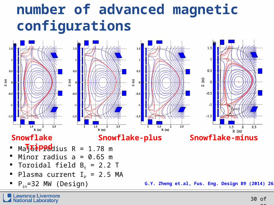
HL-2M tokamak enables a number of advanced magnetic configurations
jj
Major radius R = 1.78 m Minor radius a = 0.65 m Toroidal field Bt = 2.2 T Plasma current IP = 2.5 MA Pin=32 MW (Design)
Snowflake Snowflake-plus Snowflake-minus Tripod
G.Y. Zheng et.al, Fus. Eng. Design 89 (2014) 2621

31 of 32
Many pre-DEMO and DEMO designs include snowflake and Super-X configurations
Y. Wan, SOFE 2013
China Fusion Experimental Reactor
Z. Luo et.al, IEEE TRANSACTIONS ON PLASMA SCIENCE, V42, 2014, 1021
R Albanese et. al,PPCF, 56 (2014) 035008
Snowflake for DEMO
N. Asakura et.al, Trans. Fus. Sci. Tech. 63, 2013, 70.
Super-X and Snowflake for DEMO
Super-X for Aries Slim CSM. Kotschenreuther et. al, ARIES Workshop 2010

32 of 32
Everything New Is Actually Well-Forgotten Old (Новое – это хорошо забытое старое, the Russian saying).
A number of potentially attractive magnetic divertor configurations exist
Much research remains to be done to qualify them as • Advanced magnetic divertor configurations • Divertor candidates for a fusion reactor

Lawrence Livermore National Laboratory LLNL-PRES-xxxxxx33
Backup

Lawrence Livermore National Laboratory LLNL-PRES-xxxxxx34
The present vision for controlling the plasma–material interface of a tokamak is an axisymmetric poloidal magnetic X-point divertor. The divertor must enable access to high core and pedestal plasma performance metrics while keeping target plate heat loads and erosion within the operating limits of plasma-facing component cooling technology and target plate materials. The proposed ITER divertor is based on standard X-point geometry designs tested in large tokamak experiments and uses tilted vertical targets to generate partial radiative detachment of the strike points. However, the standard divertor approach is likely to be insufficient for next step advanced tokamak and spherical tokamak devices such as the proposed fusion nuclear science facilities and for the DEMO reactor.
Novel magnetic divertor configuration development and optimization has always been an active area in fusion plasma research. In this talk, advanced poloidal divertor concepts and experimental performance will be reviewed. Advanced divertors have the capability to modify steady-state and transient power exhaust via modifications to parallel and perpendicular transport and dissipative loss channels. The basic physics principles of these concepts will be summarized, from the first divertor for impurity control proposed by L. Spitzer for the stellarator, to long legged divertors, expanded boundaries, multiple X-point divertors, and multipole divertors for tokamaks. Many of the these divertor configurations face practical limitations on magnetic coil layout and construction. In recent years, two advanced divertor concepts have been pursued experimentally: snowflake (2nd order null) divertors, implemented in the TCV, NSTX, DIII-D and EAST tokamaks with existing magnetic coils, and the (long-legged) Super-X divertor, which is presently being implemented in MAST Upgrade using specially designed additional coils. The status and plans for research in these areas will be summarized.
Several outstanding physics and engineering problems need to be addressed in order to qualify an advanced divertor concept for a next step tokamak reactor. This talk will discuss the general issues and motivations, including coil design and placement, equilibria design and plasma real-time control, plasma-facing component design, compatibility with highly radiative scenarios, and integration with high-performance core and pedestal plasma.
This work is supported by the US Department of Energy under DE-AC5207NA27344.
Abstract

Lawrence Livermore National Laboratory LLNL-PRES-xxxxxx35
Conventional divertor history…
A. D. Sanderson et.al, J. Nucl. Mater. 76 530 (1978)
First proposal of a magnetic divertor L. Spitzer, Phys. Fluids 1 (1958) 253 (for
impurity control in a stellarator)
First use of a poloidal divertor JFT-2a (DIVA), Japan, 1975 (approx.)
First demonstration of impurity control using a divertor
JFT-2a, Japan, 1975 (approx.)
First demonstration of H-mode with a poloidal divertor
ASDEX, Germany 1982
Poloidal bundle divertor