
1 Lec 14: Heat exchangers. 2 Heat Exchangers and mixing devices Heat exchangers are devices which...
45
1 Lec 14: Heat exchangers
-
date post
19-Dec-2015 -
Category
Documents
-
view
229 -
download
0
Transcript of 1 Lec 14: Heat exchangers. 2 Heat Exchangers and mixing devices Heat exchangers are devices which...
1
Lec 14: Heat exchangers

2
Heat Exchangers and mixing devices
• Heat exchangers are devices which transfer heat between different fluids
• Mixing devices (also called open heat exchangers) combine two or more fluids to achieve a desired output, such as fluid temperature or quality

3
Heat exchangers are used in a variety of industries
• Automotive - radiator• Refrigeration - evaporators/condensers• Power production - boilers/condensers• Power electronics - heat sinks• Chemical/petroleum industry- mixing
processes

4
Heat exchangers can take a variety of shapes
5
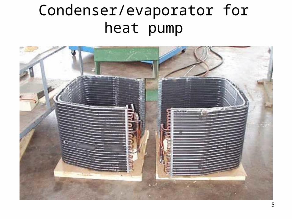
Condenser/evaporator for heat pump

6
Cooling towers are a type of heat exchanger.

7
Something a little closer to home..

8

9
Heat Exchangers
• In a closed heat exchanger, the fluids do not mix. This is a shell-and-tube heat exchanger.

10
Heat Exchangers
• Your book has very simple examples of heat exchangers. One is counterflow where the fluids flow in opposite directions in the heat exchanger:

11
Heat Exchangers
• Another type is parallel flow, where the fluids flow in the same direction:
12
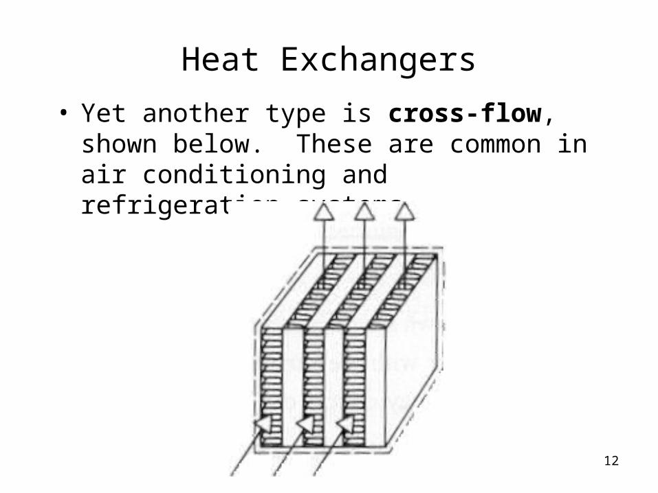
Heat Exchangers
• Yet another type is cross-flow, shown below. These are common in air conditioning and refrigeration systems.
13
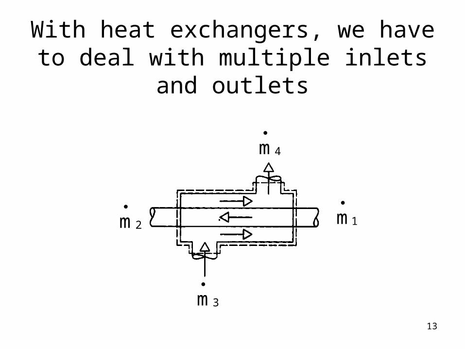
With heat exchangers, we have to deal with multiple inlets and
outlets
1m
2m
4m
3m

14
TEAMPLAYTEAMPLAY
• At steady flow, what is the relationship between
?mand,m,m,m 4321

15
What assumptions to make?
Ask yourself:• See any devices producing/using shaft
work?• What about potential energy effects?• What about kinetic energy changes?• Can we neglect heat transfer?

16
Apply conservation of mass on both streams...
dt
dmCV 0
A21 mmm
If we have steady flow, then:
And1m
2m
4m
3m
B43 mmm
Fluid A
Fluid B

17
Conservation of energy can be a little more complicated...
1m
2m
4m
3m
I’ve drawn the control volume around the whole heat exchanger.
Implications:
•No heat transfer from the control volume.
Fluid A
Fluid B

18
Conservation of energy looks pretty complicated:
A21 mmm
B43 mmm
2 2• • • •1 31 31 1 3 32 2CV
V VQ W m h gz m h gz
2 2
• •2 42 42 2 4 4 0
2 2V V
m h gz m h gz
We know from conservation of mass:

19
Conservation of energy equation for the heat exchanger
2 2• • • 1 2
1 2 1 22 2ACV
A
V VQ W m h h g z z
2 2
• 3 43 4 3 4 0
2 2B
B
V Vm h h g z z
Apply what we know about the mass flow relationships:

20
Heat Exchangers
• Generally, there is no heat transfer from or to the heat exchanger, except for that leaving or entering through the inlets and exits.
• So,• And, because the device does no work,
• Also, potential and sometimes kinetic energy changes are negligible.
0Q
0WCV
21
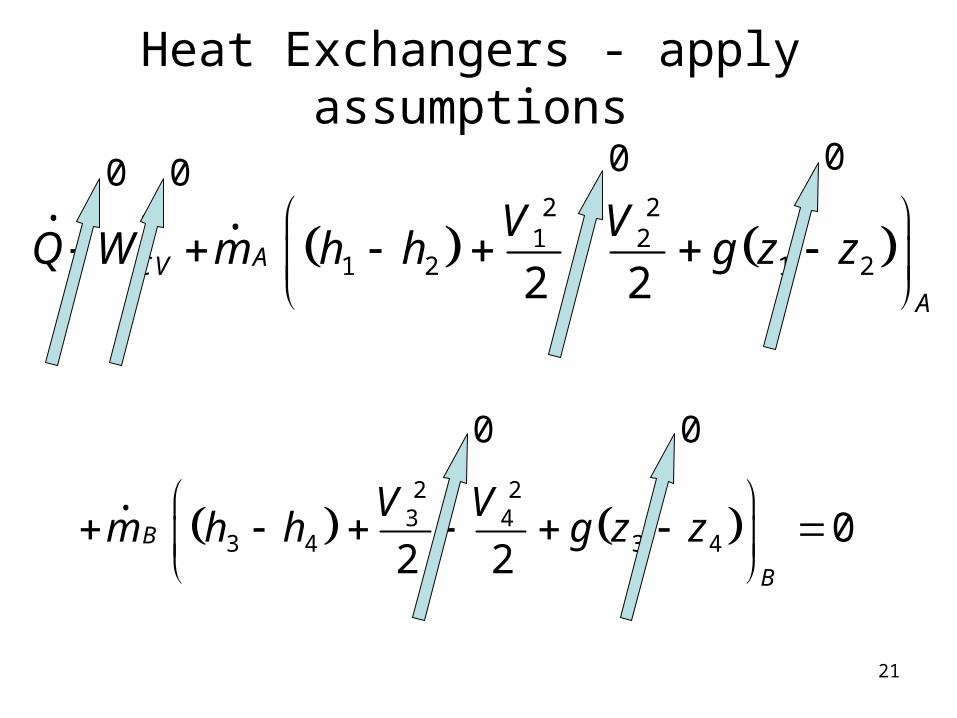
Heat Exchangers - apply assumptions
2 2• • • 1 2
1 2 1 22 2ACV
A
V VQ W m h h g z z
2 2
• 3 43 4 3 4 0
2 2B
B
V Vm h h g z z
0 0 0 0
0 0

22
Heat Exchangers
)hh(m)hh(m 34B21A
After throwing away a bunch of terms, we’re left with:
The energy change of fluid A is equal to the negative of the energy change in fluid B.

23
TEAMPLAYTEAMPLAY
How would the energy equation differ if we drew the boundary of the control volume around each of the fluids?

24
Heat Exchangers
• Now if we want the energy lost or gained by either fluid we must let that fluid be the control volume, indicated by the red.
A1 mm
2m

25
Heat Exchangers
0hhmQ 21AA,CV
12A hhq
The energy equation for one side:
Or dividing through by the mass flow:

26
Example Problem
Refrigerant 134a with a mass flow rate of 5 kg/min enters a heat exchanger at 1.2 MPa and 50C and leaves at 1.2 MPa and 44C. Air enters the other side of the heat exchanger at 34 C and 1 atmosphere and leaves at 42 C and 1 atmosphere. Calculate:
a) the heat transfer from the refrigerant in (kJ/min)
b) the mass flow rate of the air (kg/min)

27
Draw diagram
R134am 5 kg/ min
?mair
R134a INLET
T1=50C
P1 = 1.2 MPa
R134a OUTLET
T2=44C
P2 = 1.2 MPa
AIR INLET
T3=34C
P3 = 101 kPa
AIR OUTLET
T3=42C
P3 = 101 kPa
28
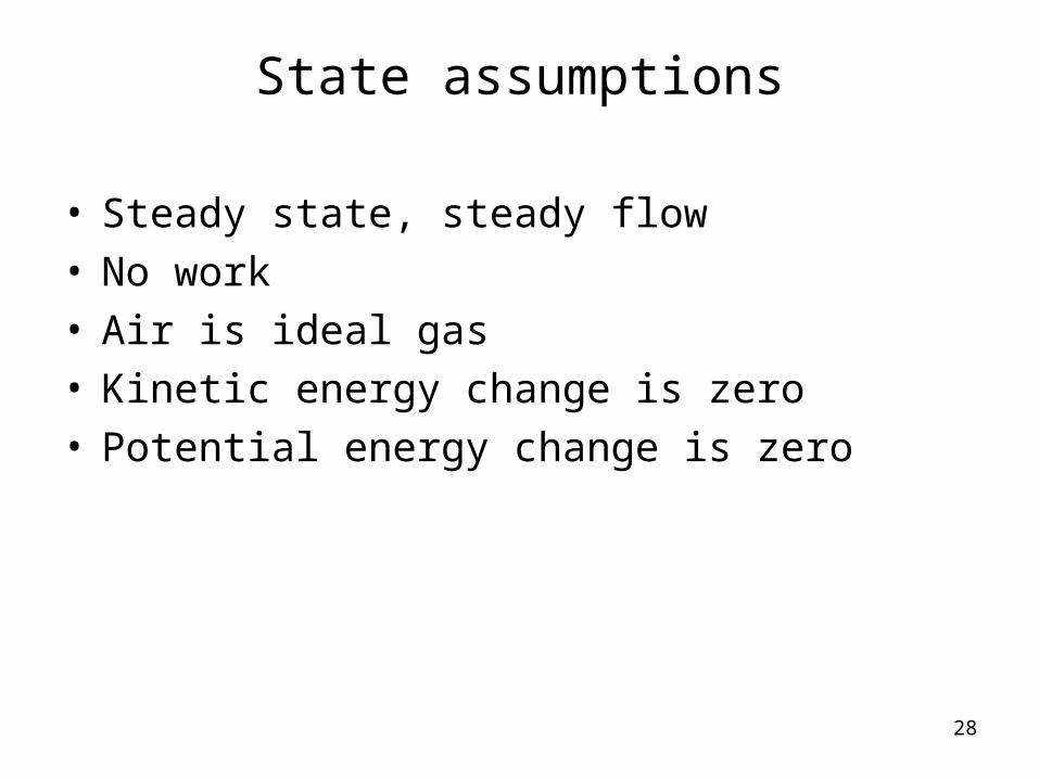
State assumptions
• Steady state, steady flow• No work• Air is ideal gas• Kinetic energy change is zero• Potential energy change is zero
29
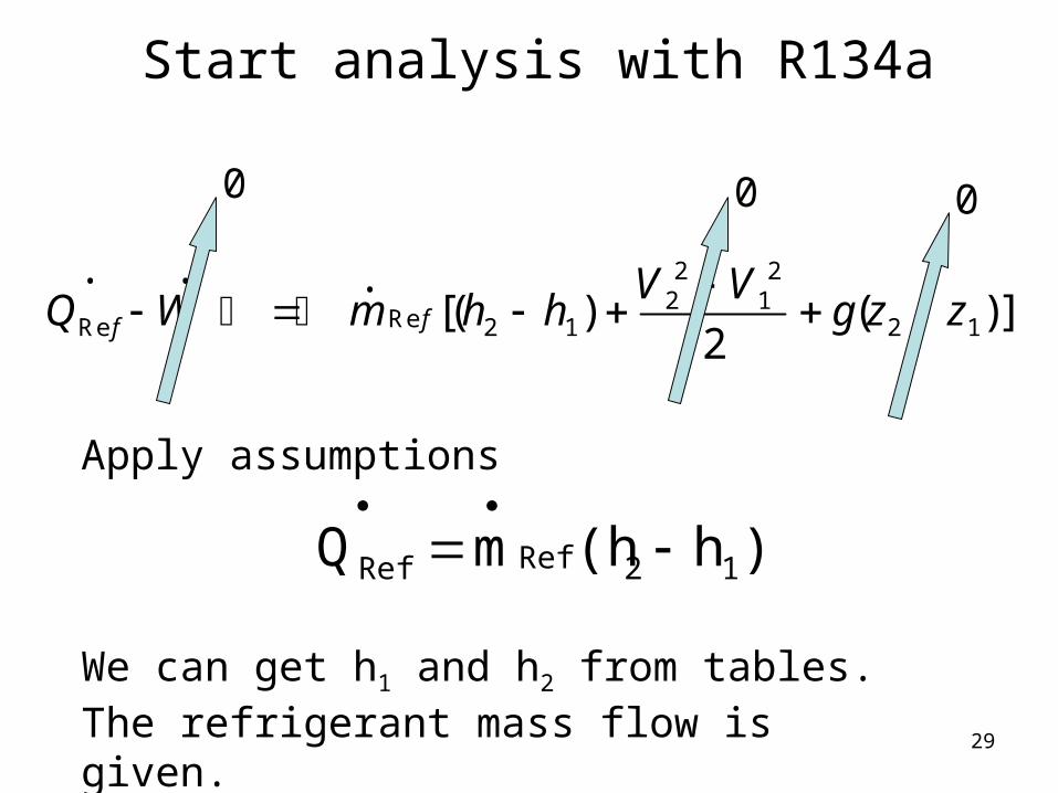
Start analysis with R134a
2 2• • • 2 1ReRe 2 1 2 1[( ) ( )]
2ff
V VQ W m h h g z z
Apply assumptions
0 0 0
)h(hmQ 12RefRef
We can get h1 and h2 from tables. The refrigerant mass flow is given.
30
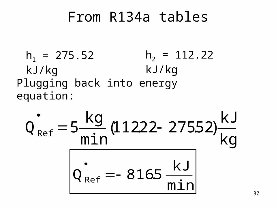
From R134a tables
h1 = 275.52 kJ/kg h2 = 112.22 kJ/kg
Plugging back into energy equation:
kg
kJ)52.27522.112(
min
kg5QRef
min
kJ5.816QRef
31
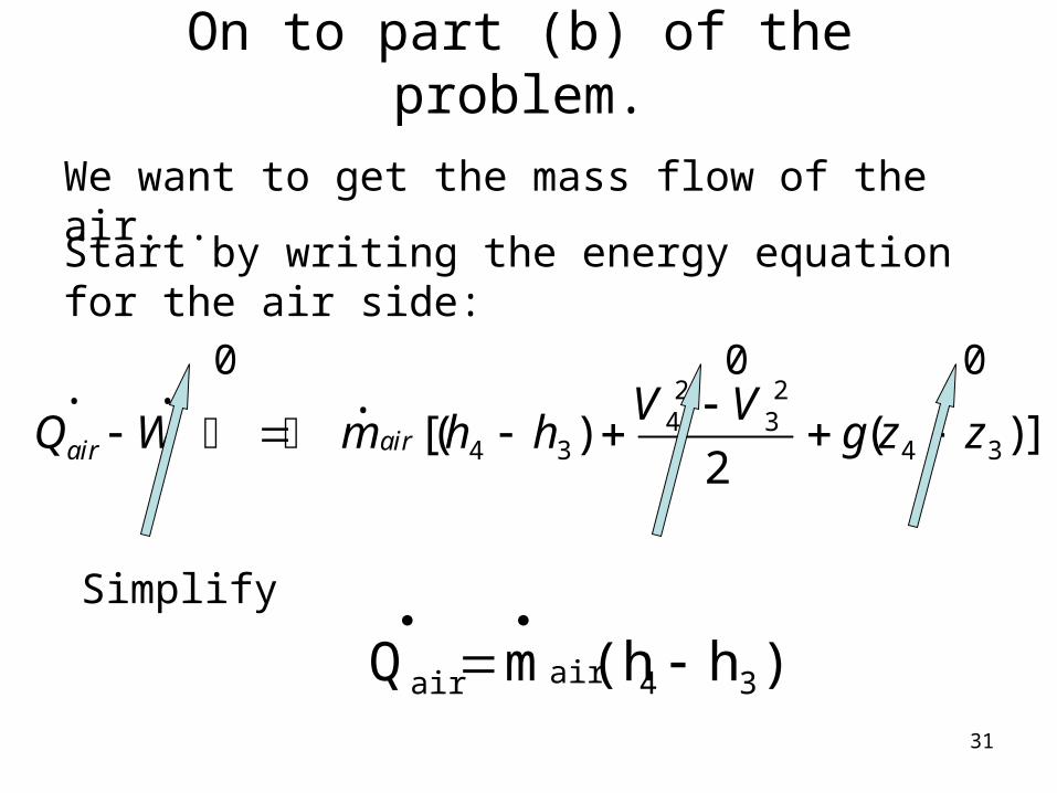
On to part (b) of the problem.
We want to get the mass flow of the air...
Start by writing the energy equation for the air side:
2 2• • • 4 34 3 4 3[( ) ( )]
2airair
V VQ W m h h g z z
Simplify
0 0 0
)h(hmQ 34airair
32
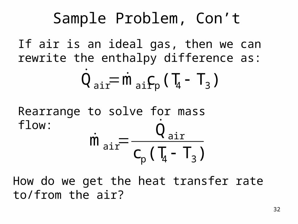
Sample Problem, Con’t
If air is an ideal gas, then we can rewrite the enthalpy difference as:
)T(TcmQ 34pairair
Rearrange to solve for mass flow:
)T(Tc
Qm
34p
airair
How do we get the heat transfer rate to/from the air?

33
Almost there!!!!!
refair QQ
We can write:
somin
kJ5.816Qair
Get specific heat from table:
kgK
kJ006.1cp
Plug in numbers from here: )K34)(42
kgKkJ
(1.006
minkJ
816.5mair
min
kg4.101mair

34
TEAMPLAYTEAMPLAY
Work problem 5-100E

35
Open heat exchangers (mixers)
• In an open heat exchanger, the fluids mix.
1,airm
2,airm
3,airm
3,air2,air1,air mmm

36
The mixer may look more like a tank
1m
2m 3m

37
Apply conservation equations for steady state, steady flow
321 mmm Mass
Energy2 2• • • •1 2
1 21 1 2 22 2V V
Q W m h gz m h gz
2• 3
3 3 3 02V
m h gz

38
Look at some typical assumptions
• Steady state, steady flow• No work• No heat transfer - not always true• Kinetic energy change is zero - usually• Potential energy change is zero - usually
39
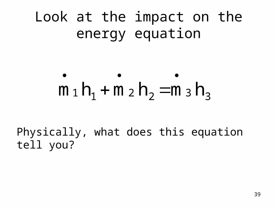
Look at the impact on the energy equation
332211 hmhmhm
Physically, what does this equation tell you?
40
Sample Problem
Water is heated in an insulated tank by mixing it with steam. The water enters at a rate of 200 lbm/min at 65°F and 50 psia. The steam enters at 600°F and 50 psia. The mixture leaves the tank at 200°F and 48 psia. How much steam is needed?

41
Draw system with knowns:
lb/min200m1
?m2 ?m3
T1 = 65°F
P1 = 50 psia
Water
Steam
T2 = 600°F
P2 = 50 psia
T3 = 100°F
P3 = 50 psia
Outlet

42
Assumptions
• Steady state, steady flow• No work• No heat transfer • Kinetic energy change is zero• Potential energy change is zero
43
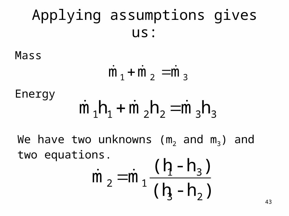
Applying assumptions gives us:
321 mmm Mass
Energy
332211 hmhmhm
We have two unknowns (m2 and m3) and two equations.
)h-(h
)h-(hmm
23
3112
44
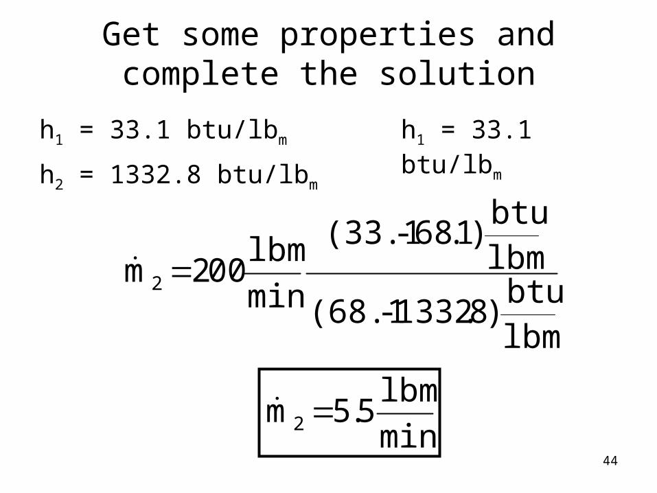
Get some properties and complete the solution
h1 = 33.1 btu/lbm
h2 = 1332.8 btu/lbm
h1 = 33.1 btu/lbm
lbmbtu
)8.1332-(68.1
lbmbtu
)1.68-(33.1
min
lbm002m2
min
lbm5.5m2

45
TEAMPLAYTEAMPLAY
Work problem 5-96


![Chapter 3 Compact heat exchangers · and lightweight heat exchangers has stimulated the development of much more com-pact heat transfer surfaces than in classical devices [44]. In](https://static.fdocuments.in/doc/165x107/5e47ef0b5933ea261c1d4ef3/chapter-3-compact-heat-exchangers-and-lightweight-heat-exchangers-has-stimulated.jpg)


