Chapter 5 Heat Exchangers - Memorial University of ...vtalimi/Chapter5.pdf · Chapter 5 Heat...
21
Chapter 5 Heat Exchangers 5.1 Introduction Heat exchangers are devices used to transfer heat between two or more fluid streams at different temperatures. Heat exchangers find widespread use in power generation, chemical processing, electronics cooling, air-conditioning, refrigeration, and automo- tive applications. In this chapter we will examine the basic theory of heat exchangers and consider many applications. In addition, we will examine various aspects of heat exchanger design and analysis. 5.2 Heat Exchanger Classification Due to the large number of heat exchanger configurations, a classification system was devised based upon the basic operation, construction, heat transfer, and flow arrangements. The following classification as outlined by Kakac and Liu (1998) will be discussed: • Recuperators and regenerators • Transfer processes: direct contact or indirect contact • Geometry of construction: tubes, plates, and extended surfaces • Heat transfer mechanisms: single phase or two phase flow • Flow Arrangement: parallel flow, counter flow, or cross flow Figure 1 shows a more comprehensive classification using these basic criteria. 105
Transcript of Chapter 5 Heat Exchangers - Memorial University of ...vtalimi/Chapter5.pdf · Chapter 5 Heat...
Chapter 5
Heat Exchangers
5.1 Introduction
Heat exchangers are devices used to transfer heat between two or more fluid streamsat different temperatures. Heat exchangers find widespread use in power generation,chemical processing, electronics cooling, air-conditioning, refrigeration, and automo-tive applications. In this chapter we will examine the basic theory of heat exchangersand consider many applications. In addition, we will examine various aspects of heatexchanger design and analysis.
5.2 Heat Exchanger Classification
Due to the large number of heat exchanger configurations, a classification systemwas devised based upon the basic operation, construction, heat transfer, and flowarrangements. The following classification as outlined by Kakac and Liu (1998) willbe discussed:
• Recuperators and regenerators
• Transfer processes: direct contact or indirect contact
• Geometry of construction: tubes, plates, and extended surfaces
• Heat transfer mechanisms: single phase or two phase flow
• Flow Arrangement: parallel flow, counter flow, or cross flow
Figure 1 shows a more comprehensive classification using these basic criteria.
105
106 Mechanical Equipment and Systems
5.3 Heat Exchanger Design Methods
The goal of heat exchanger design is to relate the inlet and outlet temperatures,the overall heat transfer coefficient, and the geometry of the heat exchanger, to therate of heat transfer between the two fluids. The two most common heat exchangerdesign problems are those of rating and sizing. We will limit ourselves to the designof recuperators only. That is, the design of a two fluid heat exchanger used for thepurposes of recovering waste heat.
We will begin first, by discussing the basic principles of heat transfer for a heatexchanger. We may write the enthalpy balance on either fluid stream to give:
Qc = mc(hc2 − hc1) (5.1)
and
Qh = mh(hh1 − hh2) (5.2)
For constant specific heats with no change of phase, we may also write
Qc = (mcp)c(Tc2 − Tc1) (5.3)
and
Qh = (mcp)h(Th1 − Th2) (5.4)
Now from energy conservation we know that Qc = Qh = Q, and that we may relatethe heat transfer rate Q and the overall heat transfer coefficient U , to the some meantemperature difference ∆Tm by means of
Q = UA∆Tm (5.5)
where A is the total surface area for heat exchange that U is based upon. Later weshall show that
∆Tm = f(Th1, Th2, Tc1, Tc2) (5.6)
It is now clear that the problem of heat exchanger design comes down to obtainingan expression for the mean temperature difference. Expressions for many flow con-figurations, i.e. parallel flow, counter flow, and cross flow, have been obtained in theheat transfer field. We will examine these basic expressions later. Two approachesto heat exchanger design that will be discussed are the LMTD method and the effec-tiveness - NTU method. Each of these methods has particular advantages dependingupon the nature of the problem specification.
5.3.1 Overall Heat Transfer Coefficient
A heat exchanger analysis always begins with the determination of the overall heattransfer coefficient. The overall heat transfer coefficient may be defined in terms of

Heat Exchangers 107
individual thermal resistances of the system. Combining each of these resistances inseries gives:
1
UA=
1
(ηohA)i
+1
Skw
+1
(ηohA)o
(5.7)
where η0 is the surface efficiency of inner and outer surfaces, h is the heat transfercoefficients for the inner and outer surfaces, and S is a shape factor for the wallseparating the two fluids.
The surface efficiency accounts for the effects of any extended surface which ispresent on either side of the parting wall. It is related to the fin efficiency of anextended surface in the following manner:
ηo =
(1− (1− ηf )
Af
A
)(5.8)
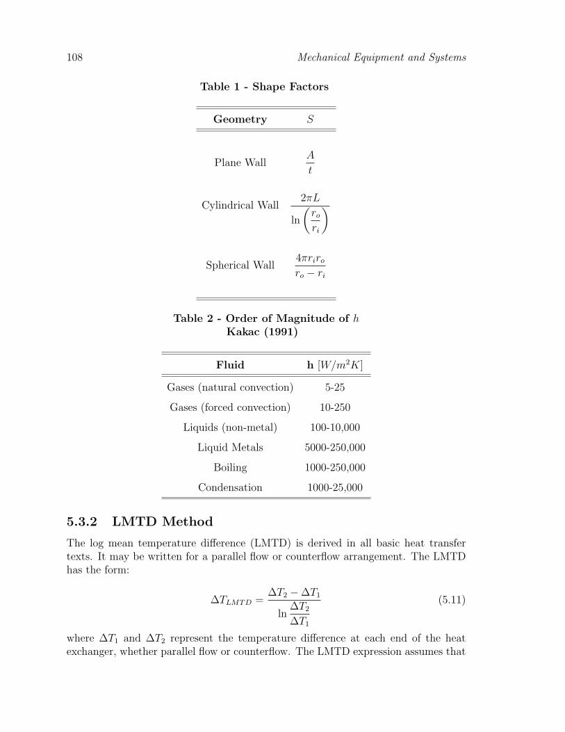
The thermal resistances include: the inner and outer film resistances, inner andouter extended surface efficiencies, and conduction through a dividing wall whichkeeps the two fluid streams from mixing. The shape factors for a number of usefulwall configurations are given below in Table 1. Additional results will be presentedfor some complex doubly connected regions.
Equation (5.7) is for clean or unfouled heat exchanger surfaces. The effects offouling on heat exchanger performance is discussed in a later section. Finally, weshould note that
UA = UoAo = UiAi (5.9)
however,
Uo 6= Ui (5.10)
Finally, the order of magnitude of the thermal resistances in the definition of theoverall heat transfer coefficient can have a significant influence on the calculation ofthe overall heat transfer coefficient. Depending upon the nature of the fluids, oneor more resistances may dominate making additional resistances unimportant. Forexample, in Table 2 if one of the two fluids is a gas and the other a liquid, then it iseasy to see that the controlling resistance will be that of the gas, assuming that thesurface area on each side is equal.
108 Mechanical Equipment and Systems
Table 1 - Shape Factors
Geometry S
Plane WallA
t
Cylindrical Wall2πL
ln
(ro
ri
)
Spherical Wall4πriro
ro − ri
Table 2 - Order of Magnitude of hKakac (1991)
Fluid h [W/m2K]
Gases (natural convection) 5-25
Gases (forced convection) 10-250
Liquids (non-metal) 100-10,000
Liquid Metals 5000-250,000
Boiling 1000-250,000
Condensation 1000-25,000
5.3.2 LMTD Method
The log mean temperature difference (LMTD) is derived in all basic heat transfertexts. It may be written for a parallel flow or counterflow arrangement. The LMTDhas the form:
∆TLMTD =∆T2 −∆T1
ln∆T2
∆T1
(5.11)
where ∆T1 and ∆T2 represent the temperature difference at each end of the heatexchanger, whether parallel flow or counterflow. The LMTD expression assumes that
Heat Exchangers 109
the overall heat transfer coefficient is constant along the entire flow length of the heatexchanger. If it is not, then an incremental analysis of the heat exchanger is required.The LMTD method is also applicable to cross flow arrangements when used with thecross flow correction factor. The heat transfer rate for a cross flow heat exchangermay be written as:
Q = FUA∆TLMTD (5.12)
where the factor F is a correction factor, and the log mean temperature difference isbased upon the counterflow heat exchanger arrangement.
The LMTD method assumes that both inlet and outlet temperatures are known.When this is not the case, the solution to a heat exchanger problem becomes some-what tedious. An alternate method based upon heat exchanger effectiveness is moreappropriate for this type of analysis. If ∆T1 = ∆T2 = ∆T , then the expression forthe LMTD reduces simply to ∆T .
5.3.3 ε−NTU Method
The effectiveness / number of transfer units (NTU) method was developed to simplifya number of heat exchanger design problems. The heat exchanger effectiveness isdefined as the ratio of the actual heat transfer rate to the maximum possible heattransfer rate if there were infinite surface area. The heat exchanger effectivenessdepends upon whether the hot fluid or cold fluid is a minimum fluid. That is thefluid which has the smaller capacity coefficient C = mCp. If the cold fluid is theminimum fluid then the effectiveness is defined as:
ε =Cmax(TH,in − TH,out)
Cmin(TH,in − TC,in)(5.13)
otherwise, if the hot fluid is the minimum fluid, then the effectiveness is defined as:
ε =Cmax(TC,out − TC,in)
Cmin(TH,in − TC,in)(5.14)
We may now define the heat transfer rate as:
Q = εCmin(TH,in − TC,in) (5.15)
It is now possible to develop expressions which relate the heat exchanger effective-ness to another parameter referred to as the number of transfer units (NTU). Thevalue of NTU is defined as:
NTU =UA
Cmin
(5.16)
It is now a simple matter to solve a heat exchanger problem when
110 Mechanical Equipment and Systems
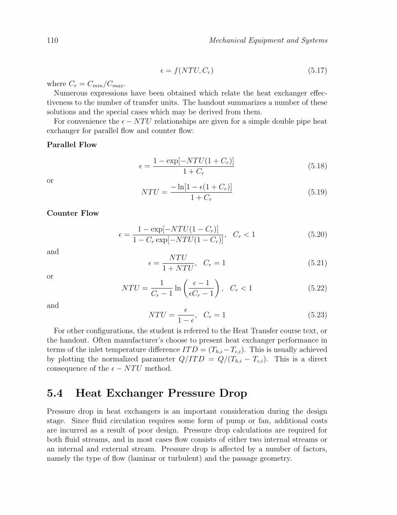
ε = f(NTU, Cr) (5.17)
where Cr = Cmin/Cmax.Numerous expressions have been obtained which relate the heat exchanger effec-
tiveness to the number of transfer units. The handout summarizes a number of thesesolutions and the special cases which may be derived from them.
For convenience the ε−NTU relationships are given for a simple double pipe heatexchanger for parallel flow and counter flow:
Parallel Flow
ε =1− exp[−NTU(1 + Cr)]
1 + Cr
(5.18)
or
NTU =− ln[1− ε(1 + Cr)]
1 + Cr
(5.19)
Counter Flow
ε =1− exp[−NTU(1− Cr)]
1− Cr exp[−NTU(1− Cr)], Cr < 1 (5.20)
and
ε =NTU
1 + NTU, Cr = 1 (5.21)
or
NTU =1
Cr − 1ln
(ε− 1
εCr − 1
), Cr < 1 (5.22)
andNTU =
ε
1− ε, Cr = 1 (5.23)
For other configurations, the student is referred to the Heat Transfer course text, orthe handout. Often manufacturer’s choose to present heat exchanger performance interms of the inlet temperature difference ITD = (Th,i−Tc,i). This is usually achievedby plotting the normalized parameter Q/ITD = Q/(Th,i − Tc,i). This is a directconsequence of the ε−NTU method.
5.4 Heat Exchanger Pressure Drop
Pressure drop in heat exchangers is an important consideration during the designstage. Since fluid circulation requires some form of pump or fan, additional costsare incurred as a result of poor design. Pressure drop calculations are required forboth fluid streams, and in most cases flow consists of either two internal streams oran internal and external stream. Pressure drop is affected by a number of factors,namely the type of flow (laminar or turbulent) and the passage geometry.
Heat Exchangers 111
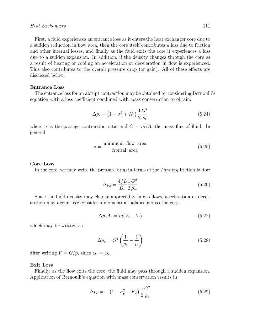
First, a fluid experiences an entrance loss as it enters the heat exchanger core due toa sudden reduction in flow area, then the core itself contributes a loss due to frictionand other internal losses, and finally as the fluid exits the core it experiences a lossdue to a sudden expansion. In addition, if the density changes through the core asa result of heating or cooling an acceleration or deceleration in flow is experienced.This also contributes to the overall pressure drop (or gain). All of these effects arediscussed below.
Entrance LossThe entrance loss for an abrupt contraction may be obtained by considering Bernoulli’s
equation with a loss coefficient combined with mass conservation to obtain:
∆pi =(1− σ2
i + Kc
) 1
2
G2
ρi
(5.24)
where σ is the passage contraction ratio and G = m/A, the mass flux of fluid. Ingeneral,
σ =minimum flow area
frontal area(5.25)
Core LossIn the core, we may write the pressure drop in terms of the Fanning friction factor:
∆pc =4fL
Dh
1
2
G2
ρm
(5.26)
Since the fluid density may change appreciably in gas flows, acceleration or decel-eration may occur. We consider a momentum balance across the core
∆paAc = m(Ve − Vi) (5.27)
which may be written as
∆pa = G2
(1
ρe
− 1
ρi
)(5.28)
after writing V = G/ρ, since Gi = Ge.
Exit LossFinally, as the flow exits the core, the fluid may pass through a sudden expansion.
Application of Bernoulli’s equation with mass conservation results in
∆pe = −(1− σ2
e −Ke
) 1
2
G2
ρe
(5.29)
112 Mechanical Equipment and Systems
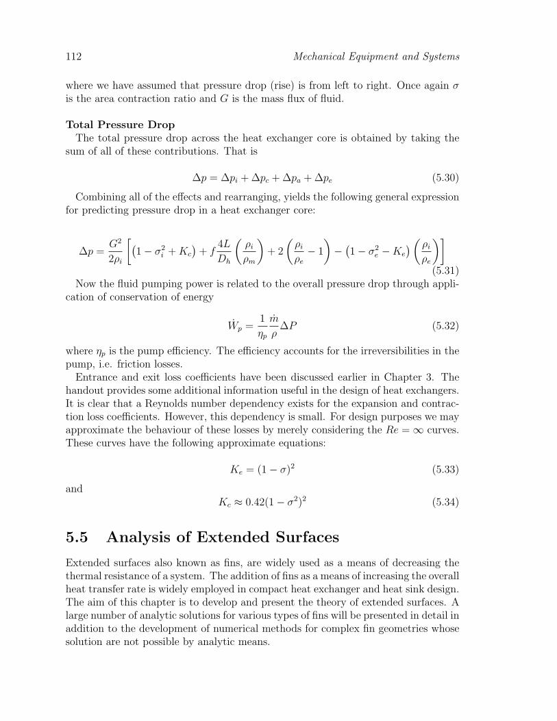
where we have assumed that pressure drop (rise) is from left to right. Once again σis the area contraction ratio and G is the mass flux of fluid.
Total Pressure DropThe total pressure drop across the heat exchanger core is obtained by taking the
sum of all of these contributions. That is
∆p = ∆pi + ∆pc + ∆pa + ∆pe (5.30)
Combining all of the effects and rearranging, yields the following general expressionfor predicting pressure drop in a heat exchanger core:
∆p =G2
2ρi
[(1− σ2
i + Kc
)+ f
4L
Dh
(ρi
ρm
)+ 2
(ρi
ρe
− 1
)−
(1− σ2
e −Ke
) (ρi
ρe
)](5.31)
Now the fluid pumping power is related to the overall pressure drop through appli-cation of conservation of energy
Wp =1
ηp
m
ρ∆P (5.32)
where ηp is the pump efficiency. The efficiency accounts for the irreversibilities in thepump, i.e. friction losses.
Entrance and exit loss coefficients have been discussed earlier in Chapter 3. Thehandout provides some additional information useful in the design of heat exchangers.It is clear that a Reynolds number dependency exists for the expansion and contrac-tion loss coefficients. However, this dependency is small. For design purposes we mayapproximate the behaviour of these losses by merely considering the Re =∞ curves.These curves have the following approximate equations:
Ke = (1− σ)2 (5.33)
andKc ≈ 0.42(1− σ2)2 (5.34)
5.5 Analysis of Extended Surfaces
Extended surfaces also known as fins, are widely used as a means of decreasing thethermal resistance of a system. The addition of fins as a means of increasing the overallheat transfer rate is widely employed in compact heat exchanger and heat sink design.The aim of this chapter is to develop and present the theory of extended surfaces. Alarge number of analytic solutions for various types of fins will be presented in detail inaddition to the development of numerical methods for complex fin geometries whosesolution are not possible by analytic means.
Heat Exchangers 113
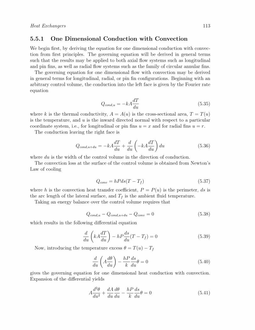
5.5.1 One Dimensional Conduction with Convection
We begin first, by deriving the equation for one dimensional conduction with convec-tion from first principles. The governing equation will be derived in general termssuch that the results may be applied to both axial flow systems such as longitudinaland pin fins, as well as radial flow systems such as the family of circular annular fins.
The governing equation for one dimensional flow with convection may be derivedin general terms for longitudinal, radial, or pin fin configurations. Beginning with anarbitrary control volume, the conduction into the left face is given by the Fourier rateequation
Qcond,u = −kAdT
du(5.35)
where k is the thermal conductivity, A = A(u) is the cross-sectional area, T = T (u)is the temperature, and u is the inward directed normal with respect to a particularcoordinate system, i.e., for longitudinal or pin fins u = x and for radial fins u = r.
The conduction leaving the right face is
Qcond,u+du = −kAdT
du+
d
du
(−kA
dT
du
)du (5.36)
where du is the width of the control volume in the direction of conduction.The convection loss at the surface of the control volume is obtained from Newton’s
Law of cooling
Qconv = hPds(T − Tf ) (5.37)
where h is the convection heat transfer coefficient, P = P (u) is the perimeter, ds isthe arc length of the lateral surface, and Tf is the ambient fluid temperature.
Taking an energy balance over the control volume requires that
Qcond,u −Qcond,u+du −Qconv = 0 (5.38)
which results in the following differential equation
d
du
(kA
dT
du
)− hP
ds
du(T − Tf ) = 0 (5.39)
Now, introducing the temperature excess θ = T (u)− Tf
d
du
(A
dθ
du
)− hP
k
ds
duθ = 0 (5.40)
gives the governing equation for one dimensional heat conduction with convection.Expansion of the differential yields
Ad2θ
du2+
dA
du
dθ
du− hP
k
ds
duθ = 0 (5.41)

114 Mechanical Equipment and Systems
The governing equation is valid for both axial and radial systems having varyingcross-sectional area and profile. The term ds/du is the ratio of lateral surface area tothe projected area. It is related to the profile function y(u) through
ds
du=
√1 +
(dy
du
)2
(5.42)
The above equation may be taken as unity, i.e. (dy/du)2 ≈ 0 for slender fin profiles,without incurring large errors. Thus, for slender fins having varying cross-sectionalarea and profile the governing equation becomes
Ad2θ
du2+
dA
du
dθ
du− hP
kθ = 0 (5.43)
The governing equation for one dimensional conduction with convection is appli-cable to systems in which the lateral conduction resistance is small relative to theconvection resistance. Under these conditions the temperature profile is one dimen-sional. The conditions for which Eq. (5.37) is valid are determined from the followingcriterion:
Bi =hb
k< 0.1 (5.44)
where Bi is the Biot number based upon the maximum half thickness of the fin profile.The fin Biot number is simply the ratio of the lateral conduction to lateral convectionresistance
Bi =Rconduction
Rconvection
=
b
kA1
hA
(5.45)
5.5.2 Boundary Conditions
The general fin equation is subject to the following boundary conditions at the fintip (u = ue)
dθ(ue)
du+
he
kθ(ue) = 0 (5.46)
for truncated fins where he is the convection heat transfer coefficient for the edgesurfaces, or
dθ(ue)
du= 0 (5.47)
the adiabatic tip condition. At the fin base (u = uo)
θ(uo) = θo (5.48)

Heat Exchangers 115
is generally prescribed.For axial fins it will be convenient to take ue = 0 and uo = L, while for radial fins
ue = ro and uo = ri. In subsequent sections, analytic results will be obtained for eachclass of fin for various profile shapes. Once the solution for the temperature excessfor a particular case has been found, the solution for the heat flow at the fin basemay be obtained from the Fourier rate equation
Qb = −kAdθ
du(5.49)
applied to the base of the fin.
5.5.3 Fin Performance
Fin performance has traditionally been measured by means of the fin efficiency or fineffectiveness. Fin efficiency may be defined as
ηf =Qb
Qmax
=Qb
hAsθb
(5.50)
where Qmax is the maximum heat transfer rate if the temperature at every pointwithin the fin were at the base temperature θb. The fin effectiveness may be definedas
ε =Qb,fin
Qb,bare
=Qb
hAbθb
(5.51)
where Qb,bare is the heat transfer from the base of the fin when the fin is not present,i.e. L→ 0.
In many heat sink design applications, it is often more convenient to consider thefin resistance defined as
Rfin =θb
Qb
(5.52)
The use of the fin resistance is more appropriate for modelling heat sink systems,since additional resistive paths may be considered.
5.5.4 Analytical Solutions
In this section we examine the many analytical solutions which have been obtainedvarious fin configurations. In most cases, the solutions for the temperature distri-bution involve special functions such as the modified Bessel functions. A thoroughreview of analytical methods pertaining to extended surfaces may be found in theclassic text by Kern and Kraus (1972). While more brief reviews are found in mostadvanced texts on heat conduction such as those by Arpaci (1966) and Schneider(1955), along with the more general advanced heat transfer texts such as those by
116 Mechanical Equipment and Systems
Jakob (1949) and Eckert and Drake (1972). Analytical methods have been success-fully applied to a number of applications of extended surfaces such as longitudinalfins, pin fins, and circular annular fins. A table of widely used solutions is providedin the class notes.
5.6 Typical Heat Exchanger Designs
We will now examine several common heat exchanger designs and discuss exampleswhich highlight the differences in each of the configurations. We shall consider: Dou-ble Pipe Heat Exchangers, Shell and Tube Heat Exchangers, Compact Heat Exchang-ers, Plate and Frame Heat Exchangers, and Boilers, Condensers, and Evaporators.
5.6.1 Double Pipe Exchangers
The double pipe heat exchanger is probably one of the simplest configurations foundin applications. It consists of two concentric circular tubes with one fluid flowinginside the inner tube and the other fluid flowing inside the annular space betweenthe tubes. Its primary uses are in cooling process fluids where small heat transferareas are required. It may be designed in a number of arrangements such as parallelflow and counterflow, and combined in series or parallel arrangements with other heatexchangers to form a system.
For this configuration the overall heat transfer coefficient is given by:
1
UA=
1
hi(2πriL)+
ln(ro/ri)
2πkwL+
1
ho(2πroL)(5.53)
where ri and ro denote the radii of the inner pipe. The heat transfer coefficient hi iscomputed for a pipe while the heat transfer coefficient ho is computed for the annulus.If both fluids are in turbulent flow, the heat transfer coefficients may be computedusing the same correlation with D = Dh, otherwise, special attention must be givento the annular region.
The pressure drop for each fluid may be determined from:
∆p =
[Σ
4fL
Dh
+ ΣK
]1
2ρV 2 (5.54)
However, care must be taken to understand the nature of the flow, i.e. series,parallel, or series-parallel.
5.6.2 Shell and Tube Exchangers
Shell and tube heat exchangers are widely used as power condensers, oil coolers,pre-heaters, and steam generators. They consist of many tubes mounted parallel toeach other in a cylindrical shell. Flow may be parallel, counter, or cross flow and in

Heat Exchangers 117
some cases combinations of these flow arrangements as a result of baffeling. Shell andtube designs are relatively simple and most often designed according to the TubularExchanger Manufacturer’s Association (TEMA) standards.
For this configuration the overall heat transfer coefficient is given by (ignoringfouling):
1
UA=
1
hiAi
+ Rw +1
hoAo
(5.55)
where Ai and Ao denote the inner and outer areas of the tubes. The heat transfercoefficient hi is computed for a tube while the heat transfer coefficient ho is computedfor tube bundles in either parallel or cross flow depending on whether baffling isused. Special attention must be given to the internal tube arrangement, i.e. baffled,single pass, multi-pass, tube pitch and arrangement, etc., to properly predict the heattransfer coefficient. Often, unless drastic changes occur in the tube count, the shellside heat transfer coefficient will not vary much from an initial prediction. Often avalue of ho = 5000 W/m2K is used for preliminary sizing.
The heat transfer surface area is calculated from:
Ao = πdoNtL (5.56)
where do is the outer diameter of the tubes, Nt is the number of tubes, and L is thelength of the tubes.
The number of tubes that can fit in a cylindrical shell is calculated from:
Nt = CTPπD2
s
4CLP 2t
(5.57)
The factor CTP is a constant that accounts for the incomplete coverage of circulartubes in a cylindrical shell, i.e. one tube pass CTP = 0.93, two tube passes CTP =0.9, and three tube passes CTP = 0.85. The factor CL is the tube layout constantgiven by CL = 1 for 45 and 90 degree layouts, and CL = 0.87 for 30 and 60 degreelayouts. Finally, Pt is the tube pitch and Ds is the shell diameter.
The shell diameter may be solved for using the above two equations, to give:
Ds = 0.637
√CL
CTP
[AoP
2t
doL
]1/2
(5.58)
The shell side heat transfer coefficient is most often computed from the followingexperimental correlation:
NuDe = 0.36Re0.55De
Pr1/3 (5.59)
for 2× 10³ < ReDe < 1× 10⁶. The effective diameter De is obtained from
De =4(P 2
t − πd2o/4)
πdo
(5.60)
118 Mechanical Equipment and Systems
for a square tube arrangement, and
De =8(√
3P 2t /4− πd2
o/8)
πdo
(5.61)
for a triangular tube arrangement. The tube side heat heat transfer coefficient iscomputed from an appropriate tube model depending on the type of flow, i.e. laminaror turbulent.
The pressure drop for the tube side is often predicted using the following formula(Kakac and Liu, 1998):
∆pt =
[4fLNp
di
+ 4Np
]1
2ρV 2 (5.62)
where Np is the number of tube passes.This accounts for tube friction and internal losses due to the return bends. The
friction factor f is computed from an appropriate tube model depending on the typeof flow, i.e. laminar or turbulent. The shell side pressure drop may be predicted from
∆ps =fG2
s(Nb + 1)Ds
2ρDe
(5.63)
and
Gs =mPt
DsCB(5.64)
where Nb is the number of baffles, C is the clearance between adjacent tubes, B isthe baffle spacing, while f is determined from
f = exp[0.576− 0.19 ln(GsDe/µ)] (5.65)
which is valid for 400 < GsDe/µ < 1 × 10⁶. These correlations have been testedagainst many shell and tube designs and have been found to provide very good results.However, care must be taken to understand the nature of the flow, i.e. parallel,cross flow, or cross flow with baffles. In general when designing shell and tube heatexchangers, the TEMA standards should be followed.
5.6.3 Compact Heat Exchangers
Compact heat exchangers offer a high surface area to volume ratio typically greaterthan 700 m2/m3 for gas-gas applications, and greater than 400 m2/m3 for liquid-gasapplications. They are often used in applications where space is usually a premiumsuch as in aircraft and automotive applications. They rely heavily on the use ofextended surfaces to increase the overall surface area while keeping size to a minimum.As a result, pressure drops can be high. Typical applications include gas-to-gasand gas-to-liquid heat exchangers. They are widely used as oil coolers, automotiveradiators, inter-coolers, cryogenics, and electronics cooling applications.

Heat Exchangers 119
For this configuration the overall heat transfer coefficient is given by:
1
UA=
1
(ηohA)i
+t
kwAw
+1
(ηohA)o
(5.66)
where ηo is the overall surface efficiency. In most compact heat exchanger designproblems, the heat transfer and friction coefficients are determined from experimentalperformance charts or models for enhanced heat transfer surfaces. The pressure dropis also computed using the general method discussed section 5.4.
5.6.4 Plate and Frame Exchangers
Plate heat exchangers consist of a series of thin corrugated formed metal plates. Eachpair of plates forms a complex passage in which the fluid flows. Each pair of platesare then stacked together to form a sandwich type construction in which the secondfluid flows in the spaces formed between successive pairs of plates. These types ofheat exchangers provide for a compact and lightweight heat transfer surface. As aresult of the small plate spacing and corrugated design, high heat transfer coefficientsresult along with strong eddy formation which helps minimize fouling. Because ofthe simple construction, they are easily cleaned and find wide use in food processingapplications.
5.6.5 Boilers, Condensers, and Evaporators
A condenser and evaporator are heat exchangers in which a change of phase results.In a condenser, a vapour is converted into a liquid, while in an evaporator (and aboiler) liquid is converted into a vapour. Due to the two phase nature of these devices,design is not as straight forward. Two phase fluid flows are much more complex thantheir single phase counterparts. Additional understanding of the phase make up anddistribution is required to perform the necessary design calculations. In addition,design correlations for two phase flows can be somewhat complicated.
5.7 Fouling of Heat Exchangers
Fouling in heat exchangers represents a major source of performance degradation.Fouling not only contributes to a decrease in thermal efficiency, but also hydraulicefficiency. The build up of scale or other deposit increases the overall thermal resis-tance of the heat exchanger core which directly reduces the overall thermal efficiency.If build up of a fouling deposit is significant, it can also increase pressure drop dueto the reduced flow area in the heat exchanger core. The two effects combined canlead to serious performance degradation. In some cases the degradation in hydraulicperformance is greater than than the degradation in thermal performance which ne-cessitates cleaning of the heat exchanger on a regular basis. Fouling of heat exchangers

120 Mechanical Equipment and Systems
results in a number of ways. The two most common are corrosion and scale buildup. However, depending upon the nature of the fluid other factors may contribute tofouling.
Table 3 - TEMA Design Fouling Resistances Rf
for a Number of Industrial Fluids
Fluid R′′f = RfA [m2K/kW ]
Engine Oil 0.176
Fuel Oil no.2 0.352
Fuel Oil no.6 0.881
Quench Oil 0.705
Refrigerants 0.176
Hydraulic FLuids 0.176
Ammonia Liquids 0.176
Ethylene Glycol Solutions 0.352
Exhaust Gases 1.761
Natural Gas Flue Gases 0.881
Coal Flue Gases 1.761
Fouling in heat exchangers is traditionally treated using the concept of a foulingresistance. This resistance is added in series to either side of the wall resistance inthe definition of the overall heat transfer coefficient.
1
UA=
1
ηihiAi
+ Rf,i +1
Skw
+ Rf,o +1
ηohoAo
(5.67)
The fouling resistance may be computed from
Rf =tf
kfAw
(5.68)
for a plane wall, and
Rf =ln(df/dc)
2πkfL(5.69)
for a tube.Unfortunately, fouling in heat exchangers has not been modelled adequately for
predictive purposes. Some typical values of fouling resistances are given in Table 3for a number of fluids.
Heat Exchangers 121
Another method of designing for fouling, is through the specification of percentageover surface, that is increasing the surface area to initially provide for a heat exchangerwhich exceeds the design heat transfer rate. This is often done for heat exchangerswhich cannot be cleaned easily such as shell and tube heat exchangers. Often as arule 25 percent over surface is prescribed. The percentage over surface is defined as
%OS =
(Af
Ac
− 1
)× 100 (5.70)
The effect that fouling has on a heat exchanger’s performance can be seen byexamining the the change in pressure drop:
∆pf
∆pc
=ff
fc
dc
df
(Vf
Vc
)2
(5.71)
If the mass flow rate is constant, then m = ρVcAc = ρVfAf , and we obtain
∆pf
∆pc
=ff
fc
(dc
df
)5
(5.72)
If the pressure drop is maintained constant, then we obtain, after substituting formass flow rate:
mf
mc
=fc
ff
(df
dc
)3
(5.73)
For any other condition, such as pump driven flow, we may solve for the newoperating point. Fouling will effectively increase the system curve, which shifts theoperating point to the left, i.e. lowering the actual flow. If the flowrate decreases,then the heat transfer coefficient also decreases. This decrease combined with theincreased resistance due to the fouling layer, leads to an overall decrease in thermalperformance, i.e. a lowering of the Q/(Th,i − Tc,i) curve.
122 Mechanical Equipment and Systems
References
Bejan, A., Heat Transfer, 1993, Wiley, New York, NY.Kakac, S. (ed.), Boilers, Evaporators, and Condensers, 1991, Wiley, New York,NY.Kakac, S. and Liu, H., Heat Exchangers: Selection, Rating, and Thermal Perfor-mance, 1998, CRC Press, Boca Raton, FL.Kays, W.M. and London, A.L., Compact Heat Exchangers, 1984, McGraw-Hill,New York, NY.Kern, D.Q. and Kraus, A.D., Extended Surface Heat Transfer, 1972, McGraw-Hill, New York, NY.McQuiston, F.C. and Parker, J.D., Heating, Ventilation, and Air Conditioning:Analysis and Design, 1988, Wiley, New York, NY.Rohsenow, W.M., Hartnett, J.P, Cho, Y.I., Handbook of Heat Transfer, 1998,McGraw-Hill, New York, NY.Shah, R.K. and Sekulic, D., Fundamentals of Heat Exchanger Design, 2003, Wiley,New York, NY.Smith, E.M., Thermal Design of Heat Exchangers, 1995, Wiley, New York, NY.

Heat Exchangers 123
PROBLEMS
Problem 5.1Consider the system described in Problem 3.1. If the heat sink temperature is
not to exceed 90 C, what is the maximum power dissipation rate for an ambienttemperature of 25 C. Ignore radiation and consider the fins as forming simple parallelplate channels. Since, the flow is effectively a channel flow and not an external ”‘flatplate” type of flow, use simple single fluid heat exchanger theory and solve the problemas a heat exchanger using an appropriate analysis method, i.e. LMTD or ε-NTU.
Problem 5.2Oil flows in a heat exchanger with a mass flow rate of 20 kg/s and is to be cooled
from 120 C to 60 C using water as a coolant flowing at a rate of 15 kg/s and aninlet temperature of 10 C. If the total heat transfer coefficient U = 1100W/m2K,determine the heat transfer area required for operation in parallel flow and counterflow. Assume that Cp,oil = 2000J/kgK and Cp,water = 4000J/kgK.
Problem 5.3Examine the following double pipe heat exchanger. Water flowing at 5000 kg/hr
is to be heated from 20 C to 35 C by using hot water from another source at 100C. If the temperature drop of the hot water is not to exceed 15 C, how much tubelength is needed in a parallel flow arrangement if a nominal 3 inch outer pipe andnominal 2 inch inner pipe are used. Assume teh inner pipe wall thickness is 1/8 inchcarbon steel with thermal conductivity k = 54 W/mK. If the heat exchanger is to becomposed of 1.25 m U-tubes connected in series, how many will be required. Also,determine the pressure drop for each fluid stream. The heat exchanger is insulatedto prevent losses, and the hot water flows in the in the annulus while the cold waterwhich is to be heated flows in the in inner pipe.
Problem 5.4You are to consider three flow arrangements for a double pipe heat exchanger:
series, parallel, series-parallel. Each configuration consists of eight pipes of equallength (L = 1 m). The inner pipe has a diameter D = 1 cm. Each configuration ofheat exchanger is to have the same overall heat transfer rate Q = 15 kW and have thesame inlet Ti = 100 C and exit Te = 85 C temperatures. Assuming that these criteriamay be met by the coolant side (annulus), calculate the expected pressure drop foreach case. In your analysis, consider minor losses and additional flow length due tothe pipe bends. The radius of the pipe bend is R = 12.5 cm, and each bend has a losscoefficient for a long radius flanged connection K = 0.2. Assume that the workingfluid in the pipe is ethylene glycol. Comment on the advantages or disadvantages ofeach configuration.
Problem 5.5Design a single pass shell and tube type heat exchanger which requires mh = 25
kg/s with Th,i = 30 C and mc = 75 kg/s with Tc,i = 20 C. What heat transfer rate
124 Mechanical Equipment and Systems
is obtained using 150 2 m tubes (ID = 16 mm and OD = 19 mm with kw = 400W/mK). The hot fluid is water and it flows in the tubes, while the cold fluid is a50/50 mix of ethylene glycol and water which flows in the shell. Assume hc = 5000W/m2K. Also, determine the minimum shell diameter assuming that the tubes arearranged in a square pattern with a pitch of 50 mm.
Problem 5.6Design a return pass shell and tube type heat exchanger using the TEMA E shell
with shell side fluid mixed, see handout. The heat exchanger is required to cool hotwater, mh = 20 kg/s with Th,i = 100 C using cold water with mc = 25 kg/s withTc,i = 20 C. What heat transfer rate is obtained using 200 5 m tubes (ID = 16 mmand OD = 19 mm with kw = 400 W/mK). The hot fluid flows in the tubes, while thecold fluid flows in the shell. Also, determine the minimum shell diameter assumingthat the tubes are arranged in a triangular pattern with a pitch of 38 mm. What isthe tube side and shell side pressure drop?
Problem 5.7Air enters a heat exchanger at 300 C at a rate of m = 0.5 kg/s. and exits with
a temperature of 100 C. If a surface similar to 1/9 − 22.68 (see handout) is used,calculate the pressure drop in the core, heat transfer coefficient for the core, and thesurface efficiency for the core. The heat exchanger core has the following dimensions:W = 10 cm, L = 30 cm, kf = 200 W/mK, tw = 1.5 mm.
Problem 5.8You wish to cool an electronic package having dimensions of 5 cm by 5 cm which
produces 100 W . The package and heat sink are to be mounted on a circuit boardwhich forms a channel with another circuit board. The spacing between the twocircuit boards is 25 mm and each board is approximately 40 cm x 40 cm. The airspeed in the channel is 3 m/s and has a temperature of 25 C. An aluminum, (k = 200W/mK, ε = 0.8), finned surface similar to that used in compact heat exchangers is tobe considered, i.e 3/32− 12.22 (see handout). It is to be attached using a conductiveadhesive tape having a thermal conductivity (ka = 50 W/mK) and thickness of 1mm. As the chief packaging engineer you must determine:
• the package temperature with the heat sink attached?
• the pressure loss coefficient for the heat sink, i.e. Ks?
• the pressure drop in the channel including the effect of the heat sink?
Assume air properties to be ρ = 1.1 kg/m3, k = 0.03 W/mK, µ = 2 × 10⁻⁵ Pas,Cp = 1007 J/kgK, Pr = 0.70.
Problem 5.9A counter flow gas turbine cooler is to be designed to recover heat from exhaust
gases. The mass flow rate for each gas stream is 2.5 kg/s, i.e. nearly balanced
Heat Exchangers 125
counter flow. The incoming air of the cold stream is 20 C and the incoming airof the high temperature gas stream is 500 C. Due to space limitations, the heatexchanger is composed of 25 channels for each gas stream and utilizes the internal finstructure with performance characteristics shown in the handout. The dimensions ofeach channel are L = 30 cm, W = 30 cm, and H = 6.35 mm. Determine the heattransfer rate Q and the outlet temperatures of each gas stream. You may neglectthe wall conduction resistance. What pressure drop results for each gas stream? Arethey the same, and if not explain. Note: the properties of air change drastically withtemperature, however you do not need to re-iterate the solution for the heat transfer,merely comment on the effect of the mean bulk temperature change. In the caseof the pressure drop calculations, use the properties given below to interpolate theoutlet air densities for each stream.
Assume properties for air at 500 C are: ρ = 0.456 kg/m3, ν = 78.5 × 10⁻⁶ m2/s,k = 0.056 W/mK, Cp = 1.093 KJ/kgK, Pr = 0.70, and at 20 C are: ρ = 1.205kg/m3, ν = 15.0× 10⁻⁶ m2/s, k = 0.025 W/mK, Cp = 1.006 KJ/kgK, Pr = 0.72.
Problem 5.10An engine oil cooler is to be designed using a 30%-70% ethylene glycol - water
mixture as a coolant. The inlet oil temperature is 95 C and is to be cooled to 75C. The coolant may be assumed to enter the heat exchanger at 85 C. The oil andcoolant flow in channels using an extended surface known as a strip fin, see attachedfigure. The required oil flow rate is limited to 75 liters per minute and while the waterflow rate is limited to 100 liters per minute. If counter flow is assumed, how manychannels N of length 50 cm and width 2.5 cm are required to cool the oil. The partingwalls may be assumed to be 2 mm in thickness. The heat exchanger is constructed ofaluminum. What is the pressure drop for each fluid across the heat exchanger core.
Problem 5.11You are to design a compact tube and fin heat exchanger. Free stream air at 25 C
and 10 m/s flows across a tube fin bundle as shown below. Water is to flow througheach tube with a rate of 0.05 kg/s and enters with a temperature of 90 C. The heatexchanger is 1 m long, and the fins are approximately 10 cm by 10 cm in size. Find:the UA for the heat exchanger, Q for the heat exchanger, and pressure drop for eachfluid.
Note: You must use the design data/chart for the air side flow (provided in class),you may assume that the fin efficiency is approximately 85
Assume properties for air at 300 K are: = 1.16 [kg/m3], = 184.6 x 10⁻⁷ [m2/s], k= 26.3 x 10⁻³ [W/mK], Cp = 1.007 [KJ/kgK], Pr = 0.71, and water at 365 K are:= 957 [kg/m3], = 2.75 x 10⁻⁴ [m2/s], k = 0.68 [W/mK], Cp = 4.082 [KJ/kgK], Pr= 1.91.