,1, Jamal Zbitou2, Mohamed Aghoutane1, Naima Amar …€¦ · · 2015-12-10final circuit is...
4
Journal of Engineering Science and Technology Review 8 (4) (2015) 131 - 134 Research Article A Novel CPW BandPass Filter Integrating Periodic Rectangular Slot Cells Fouad Aytouna* ,1 , Jamal Zbitou 2 , Mohamed Aghoutane 1 , Naima Amar Touhami 1 , Abdelouahed Tribak 3 and Mohamed Latrach 4 1 SIT Laboratory/FS, Abdelmalek Essaadi University, Tetouan, Morocco 2 FPK LMEET Laboratoy/ FSTS, Hassan 1st University, Settat, Morocco 3 Microwave group, INPT, Rabat, Morocco 4 Microwave group, ESEO, Angers, France Received 15 November 2015; Accepted 2 December 2015 ___________________________________________________________________________________________ Abstract In this paper, we introduce the design and the achievement of a Bandpass filter structure based on the use of rectangular slot cell. The originality of this work is to achieve a coplanar filter easy to integrate with microwave planar circuits and having a wide frequency bandwidth. The proposed bandpass filter is a low cost and compact planar filter structure. The final circuit is simulated by using two electromagnetic solvers, ADS and HFSS. The validation into simulation is based on using optimization methods integrated into the both solvers. Simulations have taken into account a high meshing density to cover the whole circuit. The fabricated bandpass filter has an area of 35X31mm2 and having a good insertion loss around -0.75dB in the bandwidth. The comparison between simulation and measurement results presents a good agreement. Keywords: Cpw, Bandpass Filter, Microstrip, Periodic Structure __________________________________________________________________________________________ 1. Introduction Recently, the coplanar waveguide (CPW) technology has been widely used in the design of microwave filters, antennas and other radiofrequency circuits [1-5]. Among applications of CPW structures which can be found in literature, we have many research studies on satellite systems and mobile communications [6-13]. Therefore, the aim of this research study is to use the CPW technology in order to develop a novel CPW filter with a wide frequency band and having miniature dimensions. To do so, we have to choose the technique which will be used to design such circuit. To achieve a wide frequency bandwidth bandpass filter we can find the technique based on aperture compensation technique [14], direct frequency conversion design method [15], using stepped impedance dual-mode resonator [16], etc. After studying the different techniques used for the achievement of wide frequency bandwidth bandpass filters. We propose in this work, a simple technique based on the use of CPW technology and in the same time the integration of a periodic structures permitting the enlargement of the frequency band. The periodic structure which was used is an optimized slot rectangular shape. The final bandpass filter is formed from a CPW centered line coupled to two lines in which we have etched the rectangular slot repeated periodically. The following sections, will present the different steps followed to design and to simulate the proposed bandpass filter, and at the end a comparison between simulation and measurement results. 2. Design Procedure Firstly, we have designed a 50 Ohm CPW line matched by using the following equations [17]: Fig. 1. Coplanar waveguide (CPW) line [17] There are four geometric parameters: the Gap G, the conductor width W, metal thickness t and the substrate thickness d. The characteristic impedance and the effective permittivity are given approximatly below: Effective permittivity !" = ! ! !! ! + (1) Jestr JOURNAL OF Engineering Science and Technology Review www.jestr.org ______________ * E-mail address: [email protected] ISSN: 1791-2377 © 2015 Kavala Institute of Technology. All rights reserved.
Transcript of ,1, Jamal Zbitou2, Mohamed Aghoutane1, Naima Amar …€¦ · · 2015-12-10final circuit is...
Journal of Engineering Science and Technology Review 8 (4) (2015) 131 - 134
Research Article
A Novel CPW BandPass Filter Integrating Periodic Rectangular Slot Cells
Fouad Aytouna*,1, Jamal Zbitou2, Mohamed Aghoutane1, Naima Amar Touhami1, Abdelouahed Tribak3 and Mohamed Latrach4
1SIT Laboratory/FS, Abdelmalek Essaadi University, Tetouan, Morocco
2FPK LMEET Laboratoy/ FSTS, Hassan 1st University, Settat, Morocco 3Microwave group, INPT, Rabat, Morocco 4Microwave group, ESEO, Angers, France
Received 15 November 2015; Accepted 2 December 2015
___________________________________________________________________________________________ Abstract In this paper, we introduce the design and the achievement of a Bandpass filter structure based on the use of rectangular slot cell. The originality of this work is to achieve a coplanar filter easy to integrate with microwave planar circuits and having a wide frequency bandwidth. The proposed bandpass filter is a low cost and compact planar filter structure. The final circuit is simulated by using two electromagnetic solvers, ADS and HFSS. The validation into simulation is based on using optimization methods integrated into the both solvers. Simulations have taken into account a high meshing density to cover the whole circuit. The fabricated bandpass filter has an area of 35X31mm2 and having a good insertion loss around -0.75dB in the bandwidth. The comparison between simulation and measurement results presents a good agreement. Keywords: Cpw, Bandpass Filter, Microstrip, Periodic Structure __________________________________________________________________________________________
1. Introduction
Recently, the coplanar waveguide (CPW) technology has been widely used in the design of microwave filters, antennas and other radiofrequency circuits [1-5]. Among applications of CPW structures which can be found in literature, we have many research studies on satellite systems and mobile communications [6-13]. Therefore, the aim of this research study is to use the CPW technology in order to develop a novel CPW filter with a wide frequency band and having miniature dimensions. To do so, we have to choose the technique which will be used to design such circuit. To achieve a wide frequency bandwidth bandpass filter we can find the technique based on aperture compensation technique [14], direct frequency conversion design method [15], using stepped impedance dual-mode resonator [16], etc. After studying the different techniques used for the achievement of wide frequency bandwidth bandpass filters. We propose in this work, a simple technique based on the use of CPW technology and in the same time the integration of a periodic structures permitting the enlargement of the frequency band. The periodic structure which was used is an optimized slot rectangular shape. The final bandpass filter is formed from a CPW centered line coupled to two lines in which we have etched the rectangular slot repeated periodically. The following sections, will present the different steps
followed to design and to simulate the proposed bandpass filter, and at the end a comparison between simulation and measurement results. 2. Design Procedure
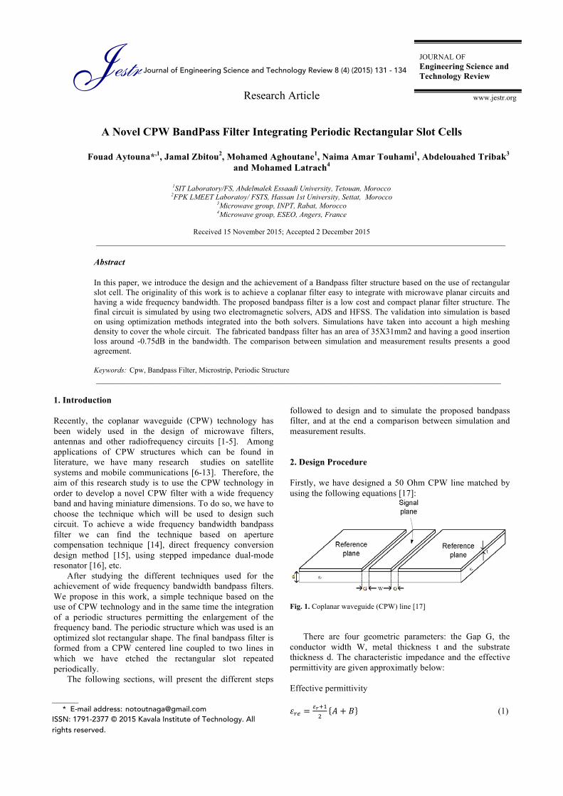
Firstly, we have designed a 50 Ohm CPW line matched by using the following equations [17]:
Fig. 1. Coplanar waveguide (CPW) line [17]
There are four geometric parameters: the Gap G, the conductor width W, metal thickness t and the substrate thickness d. The characteristic impedance and the effective permittivity are given approximatly below:
Effective permittivity 𝜀!" =
!!!!!
𝐴 + 𝐵 (1)
Jestr JOURNAL OF Engineering Science and Technology Review
www.jestr.org
______________ * E-mail address: [email protected] ISSN: 1791-2377 © 2015 Kavala Institute of Technology. All rights reserved.

Fouad Aytouna, Jamal Zbitou, Mohamed Aghoutane, Naima Amar Touhami, Abdelouahed Tribak and Mohamed Latrach/ Journal of Engineering Science and Technology Review 8 (4) (2015) 131=134
132
Where
𝐴 = tanh 0.775 lndG + 1.75
𝐵 =𝑘𝐺𝑑 0.04 − 0.7𝑘 + 0.01 1 − 0.1𝜀! 0.25 + 𝑘
𝑘 =𝑊
𝑊 + 2𝐺
Characteristic Impedance 𝑍! =
!"!!!"
!! !!(!)
(2)
where K(k) is a complete elliptical function of the first kind. We have 𝑘! = 1 − 𝑘! ; 𝐾! 𝑘 = 𝐾 𝑘′
and !!(!)!(!)
= !!ln 2 !! !!
!! !! if 0 < k < 0.707 (3)
!!ln 2 !! !!
!! !!
!! if 0.707 < k < 1 (4)
The CPW offeres many advantages, which include the following:
• It can work to extremely high frequencies (100 GHz or more).
• Good circuit isolation can be achieved using a CPW. Many examples of high-isolation RF switches have used a grounded CPW to get 60 dB isolation or more.
After the validation of the design of this CPW line, we have introduce a modification into this CPW line permitting us to a achieve a bandpass filter. The technique used, is based on the insertion of two lines coupled to the centered line and to enlarge the bandwidth we have used the periodic structure technique. The bandpass filter is designed and simulated by using Momentum integrated into ADS solver. The optimization of such circuit is done by increasing the meshing density. After many series of optimization, we have validated the bandpass filter presented in Fig.2. The periodicity of the structure provides a wide frequency bandwidth behavior.
Fig.2. The proposed bandpass filter
The different optimized parameters are shown in Table 1
Table 1. values of the different parameters of the bandpass filter
Parameters Values, mm Ws 31 Ls 53 W1 3 L1 7.5 W2 1 L2 15 L3 3.5 s 1 a 1 b 2
This filter is mounted on an FR4 substrate having a thickness of 1.6mm, a dielectric permittivity 𝜀! = 4.4 and
loss tangent tanδ = 0.025. Fig.3 indicates that the bandpass filter presents a wide frequency band from 1.283 to 3.337 GHz corresponding to -0.6dB of insertion loss and a reflexion coefficient less than -10dB. As we shown in Fig.3, we have a good rejection far from the bandwidth.
Fig. 3. S-parameters versus frequency of the designed filter

Fouad Aytouna, Jamal Zbitou, Mohamed Aghoutane, Naima Amar Touhami, Abdelouahed Tribak and Mohamed Latrach/ Journal of Engineering Science and Technology Review 8 (4) (2015) 131=134
133
(a)
(b) Fig. 4. Presents the current distribution (a) at 1GHz and (b) at 2.3 GHz.
Fig.4 presents the current distribution for a frequency 1GHz and 2.3GHz respectively out of and in the bandwidth. In order to compare the simulation results obtained by using ADS which is a 2D electromagnetic solver based on the moment method, also to take into account the dimensions of substrate, we have used another 3D electromagnetic solver HFSS. The dimensions of the substrate are 35 X 31mm2. As depicted in Fig.5, we have obtained nearly the same simulation results by using ADS and HFSS.
Fig. 5. Comparison results between HFSS and ADS of the proposed filter 3. Measurement results and discussion
After the validation of the proposed bandpass filter into simulation, we have conducted the fabrication of the final circuit as shown in Fig.6.
Fig. 6. Photograph of the fabricated Bandpass Filter
The achieved bandpass filter is measured by using a VNA from R&S, and 3.5mm Calibration Kit. The S parameters measured results are presented in Fig.7, which demonstrate a good agreement between simulation and measurement. As we can conclude, we have obtained a bandwidth of 2.054GHz with a good insertion loss. The final proposed bandpass filter can be used for DCS, ISM and WLAN applications.
Fig. 7. Simulation and measurement results of the bandpass filter 4. Conclusion
This study has come with a novel CPW wide frequency bandpass filter which operates in the bandwidth from 1.283 to 3.337 GHz with a center frequency of 2.31GHz. This structure is compact, low cost and easy for integration with radiofrequency circuits. The final proposed bandpass filter presents good performances in term of insertion loss in a wide frequency band of 2.05GHz and a good rejection. These results are due to the integration of periodic structures based on optimized rectangular slots. The different steps followed to achieve such circuit can be followed to match this structure to other frequency bandwidth. Acknowledgment We have to thank Pr. M. Latrach and his research Team RF& Microwave in ESEO Engineering institute in Angers in France for all the support brought to our research studies by permitting us to use Electromagnetic solvers and equipments.

Fouad Aytouna, Jamal Zbitou, Mohamed Aghoutane, Naima Amar Touhami, Abdelouahed Tribak and Mohamed Latrach/ Journal of Engineering Science and Technology Review 8 (4) (2015) 131=134
134
______________________________ References
1. H.Wang, and L. Zhu, “Ultra-wideband bandpass filter
using back-to-back microstrip-to-CPW transition structure”, Electron. Lett., Vol. 41, no. 24, Nov. (2005).
2. K. Li, D. Kurita, and T. Matsui, “An ultra-wideband bandpass filter using broadside-coupled microstrip-coplanar waveguide structure”, International Microwave Symposium, Long Beach, CA, USA, (2005).
3. L. Zhu, and K. Wu, “Characterization of finite-ground CPW reactive series-connected elements for innovative design of uniplanar M(H) MICs”, IEEE Trans. Microwave Theory Tech., vol. 50, no. 2, (2002).
4. M. F. Karim, A. Q. Liu, A. Alphones, X. J. Zhang, and A. B. Yu, ‘‘CPW band-stop filter using unloaded and loaded EBG structures’’, IEE Proc.-Microw. Antennas Propag., vol. 152, no. 6, (2005).
5. F. Martin, F. Falcone, J. Bonache, T. Lopetegi, M.A.G. Laso, and M.Soralla, “New periodic-loaded electromagnetic bandgap coplanar waveguide with complete spurious passband suppression”, IEEE Microwave Wireless Compon. Lett., vol. 12, no. 11,(2002).
6. J. Sor, Y. Qian, and T. Itoh, “Miniature low-loss CPW periodic structures for filter applications,” IEEE Trans. Microwave Theory Tech.,vol. 49, no. 12, (2001).
7. L. Zhu, S. Sun, and R. Li, “Microwave Bandpass Filters for Wideband Communications”,John Wiley & Sons, Inc., Vol. 232, (2011).
8. L. Zhu, S. Sun, and W. Menzel, “Ultra-wideband (UWB) bandpass filters using multiple-mode resonator”, IEEE Microwave Wireless Components Lett., Vol.1, no. 11, (2005).
9. K. Ma, K.C.B. Liang, R.M. Jayasuriya, and K.S. Yeo, “A wideband and high rejection multimode bandpass
filter using stub perturbation”, IEEE Microwave Wireless Compon. Lett., Vol.19, No.1, (2009).
10. M.K. Mandal, and S. Sanyal, “Compact wide-band bandpass filter using microstrip to slotline broadside-coupling”, IEEE Microwave Wireless Compon. Lett., Vol.17, No.9, (2007).
11. R. Schwindt, and C. Nguyen, “Spectral domain analysis of three symmetric coupled lines and application to a new bandpass filter”, IEEE Trans. Microwave Theory Tech., Vol.42, No.7, (1994).
12. J.T. Kuo, and E. Shih, “Wideband bandpass filter design with three line microstrip structures”, Proc. Inst. Electron Eng., Vol.149, (2002).
13. J.T.Kuo, and E.Shih, “Wideband bandpass filter design with three-line microstrip structures”, Microwave, Antennas and Propagation IEEE Proceeding., (2002).
14. L. Zhu, H. Bu, and K. Wu, “Aperture compensation technique for innovation design of ultra broadband microstrip bandpass filter”, in IEEE MTT-S Int. Microwave Symp Dig., Vol.1, (2000).
15. Jong-ImPark, Sung-Keun Chang, Jongsik Lim, Yong-Ku Jun, and Dal Ahn, “New Design Technique for Wide BandPass Filters using Direct Frequency Conversion Design Method”, International Symposium on Signals Systems and Electronics (ISSSE), (2007).
16. Z.Xiao, D.C.Ma, L.L.Xiang, H.H.Hu, and S.Gao, “Design of compact ultra-wideband filter using stepped impedance dual-mode resonator”, International Symposium on signals Systems and Electronics (ISSSE), Vol.2, (2010).
17. Y.Huang, and K. Boyle, “Antennas from theory to practice”, A John Wiley and Sons, Ltd, Publication, Edition 2008.


![Steering Committee03 10final[2]](https://static.fdocuments.in/doc/165x107/547e8be8b4af9fcb198b4722/steering-committee03-10final2.jpg)