1 Introduzione R4 Colore - · PDF fileThe first number represents the lower category...
18
09/2008 GENERAL INFORMATION DC Film Capacitors Please refer to our Internet address (http://www.kemet.com) for updated information on KEMET products, services and news. Contents Pitch Rated Voltage Capacitance Page mm Vdc range range General Information .......................................................................................................................................... 2 to 18 Technical terms explanation............................................................................................................................. 2 Application notes - safety conditions................................................................................................................ 3 Typical properties and applications ................................................................................................................. 13 Typical graphs.................................................................................................................................................. 13 Product code system and date code................................................................................................................ 14 Lead taping & packaging ................................................................................................................................. 15 Polyester capacitors ......................................................................................................................................... 19 to 60 Contents ......................................................................................................................................................... 19 Typical graphs ................................................................................................................................................. 20 Axial series......................................................................................................................................................... 21 to 25 A50 Series ................................................................. 50...1000 1000pF...10µF 21 Box series ................................................................................................................................................... 26 to 54 R82 Series ................................................................. 5 50...400 1000pF...4.7µF 26 RSB Series ................................................................. 5 50...630 1000pF...2.2µF 31 R66 Series ................................................................ 7.5 50...630 1000pF...4.7µF 36 R60 Series ........................................................... 10...37.5 50...1000 1000pF...220µF 41 JSP . 55 Polypropylene capacitors ............................................................................................................................... 61 to 144 Contents ..................................................................................................................................................... 61 Typical graphs.................................................................................................................................................. 62 to 63 Axial series ..................................................................................................................................................... 64 to 73 A70 Series .................................................................. 160...630 1000pF...4.7µF 64 A72 Series .................................................................. 100...2000 47pF...0.33µF 69 Box series ..................................................................................................................................................... 74 to 144 R71 Series ............................................................10...37.5.......... 420...1000 ........ 0.01µF...22µF..... 74 R73 Series ........................................................... 15...37.5 100...2000 100pF...2.2µF 79 R74 Series ........................................................... 10...37.5 250...900 Vac 470pF...3.3µF 89 R74 Series (MINIversion) ....................................... 10...15 600Vac 470pF...0.018µF 96 R74 Series (125°C) .............................................. 10...22.5 500...700Vac 470pF...0.018µF 100 R75 Series (High performances).......................... 7.5...37.5 160...2000 220pF...33µF 105 R76 Series ........................................................... 7.5...37.5 250...2000 100pF...15µF 116 R77 Series ........................................................... 10...27.5 250...900Vac 1000pF...0.1µF 128 R79 Series ................................................................. 5 160...630 1000pF...0.22µF 134 JSP Series (MKP) ............................................... 22.5...37.5 250...630 1µF...56µF 139 Interference Suppression capacitors, RC units and Modules.......................... ................................145 to 176 Contents ..................................................................................................................................................... 145 Information on International Standards - Tests related to IEC 60384-14................................................................146 Typical graphs.................................................................................................................................................. 149 Interference suppression..................................................................................................................................... 150 to 171 Box series ......................................................................................................................................................... 150 to 171 R.46 Series ................................................................ 10...37.5 275...300 Vac 0.01µF...10µF 150 R.47 Series ................................................................ 10...37.5 440...520 Vac 4700pF...2.2µF 159 R.49 Series ................................................................ 10...37.5 310 330 Vac 0.01µF...6.8µF 165 R.41 Series ................................................................ 7.5...37.5 300 Vac 1000pF...1µF 169 RC units ......................................................................................................................................................... 171 Box series ......................................................................................................................................................... 171 1.43 Series .................................................................15...27.5 275 Vac ........... 0.01µF...1µF...... 171 Modules ......................................................................................................................................................... 172 to 175 Box series ......................................................................................................................................................... 172 F5A Series ................................................................... 5...10 ................ 5...63 ............. 0.1µF...3.3µF ..... 172 F5B Series ................................................................... 5...10 ................ 5...63 ............. 0.1µF...3.3µF ..... 174 Capacitive power supply application......................................................................................................... 177 to 184 Contents ......................................................................................................................................................... 177 Short guide to choose the right film capacitor used in series with the main.......................................................... 178 Box series ...................................................................................................................................................... 180 R603 ................. Series ............................................ 22.5...37.5 300 Vac 0.15µF...6.8µF ......... 180 R752-R75L............... Series ............................................. 15...37.5 230...250 Vac 0.056µF...10µF.......... 182
Transcript of 1 Introduzione R4 Colore - · PDF fileThe first number represents the lower category...
09/2008
General information
DCFilmCapacitorsPlease refer to our internet address (http://www.kemet.com) for updated information on KEMETproducts, services and news.
Contents Pitch RatedVoltage Capacitance Page mm Vdcrange range
General information.......................................................................................................................................... 2to18Technicaltermsexplanation............................................................................................................................. 2Applicationnotes-safetyconditions................................................................................................................ 3Typicalpropertiesandapplications................................................................................................................. 13Typicalgraphs.................................................................................................................................................. 13Productcodesystemanddatecode................................................................................................................ 14Leadtaping&packaging................................................................................................................................. 15
Polyester capacitors......................................................................................................................................... 19to60Contents......................................................................................................................................................... 19Typicalgraphs................................................................................................................................................. 20
axial series......................................................................................................................................................... 21to25A50 Series................................................................. 50...1000 1000pF...10µF 21
Box series ................................................................................................................................................... 26to54R82 Series................................................................. 5 50...400 1000pF...4.7µF 26RSB Series................................................................. 5 50...630 1000pF...2.2µF 31R66 Series................................................................7.5 50...630 1000pF...4.7µF 36R60 Series........................................................... 10...37.5 50...1000 1000pF...220µF 41JSP .
55
Polypropylene capacitors............................................................................................................................... 61to144Contents ..................................................................................................................................................... 61Typicalgraphs.................................................................................................................................................. 62to63
axial series ..................................................................................................................................................... 64to73A70 Series.................................................................. 160...630 1000pF...4.7µF 64A72 Series.................................................................. 100...2000 47pF...0.33µF 69
Box series ..................................................................................................................................................... 74to144R71 Series............................................................10...37.5..........420...1000........ 0.01µF...22µF..... 74
R73 Series........................................................... 15...37.5 100...2000 100pF...2.2µF 79R74 Series........................................................... 10...37.5 250...900Vac 470pF...3.3µF 89R74 Series(MINIversion).......................................10...15 600Vac 470pF...0.018µF 96R74 Series(125°C).............................................. 10...22.5 500...700Vac 470pF...0.018µF 100R75 Series(Highperformances)..........................7.5...37.5 160...2000 220pF...33µF 105R76 Series...........................................................7.5...37.5 250...2000 100pF...15µF 116R77 Series........................................................... 10...27.5 250...900Vac 1000pF...0.1µF 128R79 Series................................................................. 5 160...630 1000pF...0.22µF 134JSP Series(MKP)...............................................22.5...37.5 250...630 1µF...56µF 139
interference Suppression capacitors, rC units and modules.......................... ................................145to176 Contents ..................................................................................................................................................... 145
InformationonInternationalStandards-TestsrelatedtoIEC60384-14................................................................146Typicalgraphs.................................................................................................................................................. 149
interference suppression..................................................................................................................................... 150to171Box series......................................................................................................................................................... 150to171
R.46 Series................................................................ 10...37.5 275...300Vac 0.01µF...10µF 150R.47 Series................................................................ 10...37.5 440...520Vac 4700pF...2.2µF 159R.49 Series................................................................ 10...37.5 310330Vac 0.01µF...6.8µF 165R.41 Series................................................................7.5...37.5 300Vac 1000pF...1µF 169
rC units ......................................................................................................................................................... 171Box series......................................................................................................................................................... 171
1.43 Series.................................................................15...27.5 275Vac........... 0.01µF...1µF...... 171modules ......................................................................................................................................................... 172to175
Box series......................................................................................................................................................... 172F5A Series................................................................... 5...10................5...63.............0.1µF...3.3µF..... 172F5B Series................................................................... 5...10................5...63.............0.1µF...3.3µF..... 174
Capacitive power supply application......................................................................................................... 177to184Contents......................................................................................................................................................... 177
Short guide to choose the right film capacitor used in series with the main..........................................................178 Box series...................................................................................................................................................... 180
R603 ................. Series............................................22.5...37.5 300Vac 0.15µF...6.8µF.........180R752-R75L............... Series............................................. 15...37.5 230...250Vac 0.056µF...10µF..........182

09/2008 2
General information
teChniCal termS exPlanationrated capacitanceCapacitancereferredto1kHz,20±1°C,65±2%ofrelativehumidityand96±10kPa.IncaseofdoubtpleaserefertoIEC60068-1,sub-clause5.2.Capacitance toleranceAdmittedcapacitancedeviationfromtheratedcapacitance.rated temperature (tr)The maximum ambient temperature surrounding the capacitor or hottest contact point (e.g. tracks),whichever is higher, at which the rated voltage Vdc or Vac at 50 Hz may be continuously applied.rated voltage (Vr)Themaximumdirectvoltageorthemaximumr.m.s.alternatingvoltage(50Hz)orthepeakvalueofapulsevoltage which may be continuously applied to a capacitor at any temperature between the lower category temperatureandtheratedtemperature.Category voltage (Vc)Themaximumdirectvoltageorthemaximumr.m.s.alternatingvoltageorthepeakvalueofapulsevoltagewhich may be continuously applied to a capacitor at its upper category temperature.temperature derated voltageThe maximum voltage that may be continuously applied to a capacitor for any temperature between the ratedtemperatureandtheuppercategorytemperature.Climatic categoryThe climatic category which the capacitor belongs to is expressed in numbers (standard IEC 60068-1: example55/100/56).The first number represents the lower category temperature (example: -55°C); the second number the upper category temperature (example: +100°C) and the third number represents the number of days relevant to the damp heat test (example: 56 days).operating temperature rangeThe operating temperature of the capacitor is defined as the ambient temperature + self temperature raise + temperature raise due to thermal radiation from other heat sources.Temperature coefficient of capacitance (αi)The change rate of capacitance with temperature measured over a specified range of temperature. It is normally expressed inpartspermillionperCelsiusdegree(10-6/°C)andreferredto20°C
CI-Coαi= Co(Ti-To)
where: Ci = Capacitance at temperature Ti Co=Capacitanceattemperature20±2°C
FormoredetailspleaserefertoEN130000.Variation of capacitance with humidityThe capacitance of a plastic film capacitor changes with the ambient humidity. The capacitance change dependsuponthedielectrictype.Pleaserefertothegraphatpage12.Dissipation factor (tgδ)The dissipation factor is the ratio between the resistive and the reactive part of the impedance of the capacitor submitted to a sinusoidal voltage of specified frequency.insulation resistance (ir) / time constantThe insulation resistance is the ratio between an applied D.C. voltage and the resulting leakage current afteraminuteofcharge.ItisexpressedinMΩ. The time constant is expressed in seconds with the following formula:
t[s]=Ir[MΩ]xC[µF].Itstatesthetimenecessarytoreducethevoltagetotheterminalsofthecapacitorat37%ofafullychargedcapacitorvalue.Pulse rise time (dv/dt) and K0The pulse rise time defines the capability of a capacitor to withstand high current peaks due to fast voltagechanges.The peak current is defined by the following formula:
Ip(peakcurrent)=Cxdv/dtwhere: Ip in A; C in µF; dv/dt in V/µs K0 is the content of energy of the wave-form applied to the capacitor and it is defined by the following formula:
K0=2∫0
τ(dv/dt)2dt
where: τ (pulse width) in µs; K0inV2/µs.Themaximumvaluesofdv/dtandK0mentionedinthiscataloguemustnotbeexceededinordertopreventadangerousoverheatingofthecapacitor.
09/2008
General information
aPPliCation noteS - Safety ConDitionS
1. operating voltage
1.1 rated voltage (Vr)
Ratedvoltageisthemaxvoltagethatmaybecontinuouslyappliedattheratedtemperature.Valueshigherthantheratedvoltagemaycauseaperforationinthecapacitordielectricorashortcircuit.Metallizedcapacitorshaveself-healingpropertiesand theapplicationofvoltageshigherthan rated voltage will not cause an immediate short circuit. Instead, what may occur, is a progressive drop in the insulation resistance with a possible risk of smoke or fire, depending upon the type of electric circuit in which the capacitor is working.TheratedvoltageofthecapacitorisusuallyD.C.If a capacitor marked D.C. is used as an A.C. capacitor, the maximum working voltage is limitedby theheat producedor bymicrodischarges that could takeplace inside thecapacitor. Do not use A.C. voltages higher than those specified in the catalogue for each series.Note:a) The A.C. voltages described in the catalogue refer to a sinusoidal wave-form. In case of
other types of waveforms or for working conditions different from those described in the catalogue,pleasecontactourTechnicalServicebeforeusingthecapacitors.
b) Ifthecapacitorissubjecttovoltageshigherthantheratedvoltage,caused,forexample,by the bad functioning of other equipment, it might be necessary to use a protection device.
c) The Rated Voltage (Vac) can be applied during the whole life of the capacitor in case you are using a suppressor series or those quoting “A.C. APPLICATIONS”. Inanyothercase,theVaccanbeappliedforamax.operatingtimeof1000hours.
1.2 Derating of rated voltage for high operating temperature
In case of a plastic film capacitor, the operating temperature (the temperature measured onthehottestpointofthecapacitor)dependsuponthetypeofdielectricused,theambienttemperature in which the capacitor is placed, the type of voltage applied (A.C. or D.C.) and in case of pulse applications, upon the value of current and frequency applied.Theratedvoltage(VR) is the maximum voltage that can be applied at a temperature ≤ the ratedtemperature.For temperatures higher than the rated temperature it is necessary to apply a voltagederatingtopreventanydamagestothedielectricofthecapacitor.This derating depends, in general, upon the type of dielectrics used (polyester,polypropylene,etc.).The catalogue quotes the limits for each series.
09/2008
General information
2. Dissipation (a.C. applications)When a capacitor is used in A.C. applications at high frequency, internal heating of the capacitor may follow with a possible risk of smoke or fire. This is caused by the heating effect of the current flowing through the internal resistance of the capacitor. The formula used to calculat the max power dissipated by the capacitor is the following:
NNl
2rmsciPcmax= ∑iV
2rmsci x 2fixCxtgδmax(fi) = ∑i xtgδmax(fi)
11 2fixCwhere:Pcmax = max dissipated power in wattVrmsci =r.m.s.voltageoftheithharmonicinvoltIrmsci =r.m.s.currentoftheithharmonicinamperefi = frequency of the ithharmonicinhertzC =capacitanceinfaradtgδmax(fi) = max. dissipation factor corresponding to the frequency of the ithharmonicN = number of significant harmonicsVrmsci(Irmsci)isrelatedtoVpp(Ipp ) as shown in Fig. 2 at page 8.In case of sinusoidal wave-form (N = 1) the formula to calculate Pcmax becomes: l2rmscPcmax=V2rmscx 2fxCxtgδmax(f)= xtgδmax(f)
2f x C(tocalculatethePcmax for some typical wave-forms, it is possible to use the approximate formulasofVrmscandIrmsclistedinthetable1atpage5).∆Tlim = allowed capacitor overtemperature in °C.Th =max.ambienttemperaturesurroundingthecapacitororhottestcontactpoint (e.g. tracks), whichever is higher, in the worst operation conditions in °C.
Box typeForTh≤ 40°C∆Tlim = 40°C for film-foil polypropylene capacitors (KP), polypropylene capacitors with double sided metallized film electrodes (MMKP), metallized polyester film capacitors(MKT).∆Tlim = 20°C for polypropylene capacitors with single sided metallized film electrodes(MKP).
Theoutlineof∆Tlimvs.Thisrepresentedinthegraphatpage6.The formula used to calculate the max. power that may be dissipated by the capacitor is: ∆TlimPclim= Rthwhere:Pclim = maximum power that may be dissipated by the capacitor in WRth =thermalresistanceofthecapacitorin°C/W(seetable2atpage5).∆Tlim = allowed capacitor overtemperature in °CIt must be: Pcmax ≤ PclimIn case of a sinusoidal wave-form the graphs of V(f) are illustrated in the pages of the cataloguerelativetoeachseries.
Warning:apart from the derating of the voltage versus the working frequency it is also necessary to consider the derating of the voltage versus the working temperature (see paragraph 1.2).Do not hesitate to contact our Technical Service for any doubts or more detailedinformation.

09/2008
General information
Pitch Box Rth
B H L(mm) (mm) (°C/W)
5.0
2.5 6.5 7.2 1273.5 7.5 7.2 1114.5 9.5 7.2 945.0 10.0 7.2 906.0 11.0 7.2 827.2 13.0 7.2 73
7.5
2.5 7.0 10.0 1073.0 8.0 10.0 983.5 6.5 10.5 1003.5 8.5 10.5 914.0 9.0 10.5 865.0 11.0 10.5 756.0 12.0 10.5 69
10.04.0 9.0 13.0 795.0 11.0 13.0 696.0 12.0 13.0 64
15.0
4.0 10.0 18.0 655.0 11.0 18.0 606.0 12.0 18.0 567.5 13.5 18.0 516.0 17.5 18.0 487.5 14.5 18.0 498.5 14.5 18.0 489.0 12.5 18.0 507.5 18.5 18.0 45
10.0 16.0 18.0 4413.0 12.0 18.0 4511.0 19.0 18.0 40
22.5
6.0 15.0 26.5 436.5 13.5 26.5 447.0 16.0 26.5 418.5 17.0 26.5 38
10.0 18.5 26.5 3611.0 20.0 26.5 3413.0 22.0 26.5 31
27.5
9.0 17.0 32.0 3510.0 20.0 32.0 3211.0 20.0 32.0 3113.0 22.0 32.0 2913.0 25.0 32.0 2814.0 28.0 32.0 2615.0 24.5 32.0 2718.0 33.0 32.0 2322.0 37.0 32.0 21
37.5
11.0 22.0 41.5 2713.0 24.0 41.5 2516.0 28.5 41.5 2319.0 32.0 41.5 2120.0 40.0 41.5 1924.0 44.0 41.5 1730.0 45.0 41.5 16
WAVE-FORM eleCtriCal ParameterS
Vpp tVrmsc= 1.04 2T
Ipp/2 tIrmsc= 1.04 2T
1f= 2t
1tgδmaxatf= 2t
VppVrmsc= 22
IppIrmsc= 22
1f= T
1tgδmaxatf= T
8 Vi2 t
Vrmsc=∑ i=1 2 2T
8 Ii2 t
Irmsc=∑ i=1 2 2T
1f= t
1tgδmaxatf= t
3T-4tVrmsc=Vpp 12T
1f= T 1tgδmaxatf= 4t
Table1 Table2
note: for axial type see page 6.

09/2008
General information
Maximum Self-heating rise for series in Axial configuration.
Series Costruction Configuration MaximumambientTemperature
MaximumSelfTemperaturerise
A50 MKT Axial 85°C 10°CA70 MKP Axial 85°C 10°CA72 MKPFilmfoil Axial 85°C 10°C
maximum overtemperature ∆Tlim vs. Th for Box type

09/2008
General information
3. Permissible currentThe main effect produced by the current flowing through the capacitor is overheating.If the heating is excessive, the capacitor might deteriorate, which could cause a short or open circuit of the capacitor or a fire.The heating of the capacitor can be caused by two different types of currents:
3.1 Effective current (r.m.s. current) given by a periodic wave-form, causing the entire body of the capacitortoheatup.
3.2 Peak of current caused by a pulse wave-form. • When a medium-high current pulse flows through the capacitor for a very short time (µs/ns),
alocalizedheatingoftheendsofthecapacitormighttakeplaceduetotheresistanceofthecontacts between the leads and end spray and between the end spray and the electrodes ofthecapacitor.These conditions usually take place mainly in the following type of circuits: switching, snubber, fly-back and S-correction.
• The parameters that define this type of phenomenon are dv/dt (pulse rise time) and Ko. The pulse rise time defines the capability of a capacitor to withstand high current peaks due to fast voltage changes. The peak current is defined by the following formula:
Ip(peakcurrent)=Cxdv/dt
where: Ip in A; C in µF; dv/dt in V/µs K0 is the content of energy of the wave-form applied to the capacitor and it is defined by the following formula:
K0=2∫0
τ(dv/dt)2dt
where: τ = pulse width. K0isexpressedinV2/µs. Themaximumvaluesofdv/dtandK0mentionedinthiscataloguemustnotbeexceededinordertopreventadangerousoverheatingofthecapacitor.Ifmorethan10,000pulsesareapplied,pleasekindlycontactourTechnicalService,unlessyouareusingseriesA72,R73,R74,R75,R76,R77,R79,RSB.
Warning:If thecapacitor issubjectedtor.m.s.andpulsecurrentshigherthanthoseadmitted,causedfor example by a bad functioning of any other equipment, we suggest the use of a protection device.
09/2008 8
General information
4. operating temperature
4.1 ∆T(overtemperatureofacapacitor).As described in the previous paragraphs, when a capacitor is used in A.C. applications the current that flows through the capacitor makes it heat up. If the capacitor heats up too much it might deteriorate causing a short circuit or fire. It is essential that the limits described in thecataloguearenotexceededand thata temperaturecheckon thecapacitor ismadewhenever it is under heavy load.
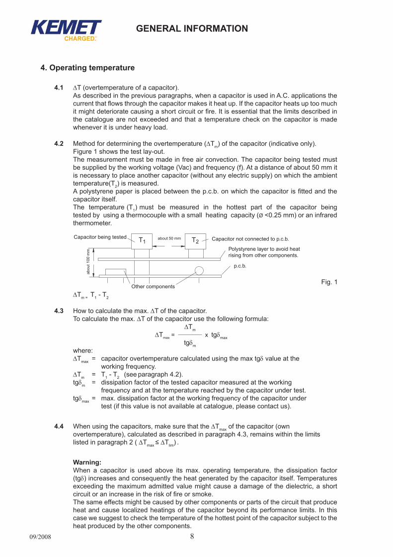
4.2 Methodfordeterminingtheovertemperature(∆Tm)ofthecapacitor(indicativeonly).Figure 1 shows the test lay-out.Themeasurementmustbemadeinfreeairconvection.Thecapacitorbeingtestedmustbe supplied by the working voltage (Vac) and frequency (f). At a distance of about 50 mm it is necessary to place another capacitor (without any electric supply) on which the ambient temperature(T2)ismeasured.A polystyrene paper is placed between the p.c.b. on which the capacitor is fitted and the capacitoritself.Thetemperature(T1)mustbemeasuredinthehottestpartofthecapacitorbeingtested by using a thermocouple with a small heating capacity (Ø<0.25mm)oraninfraredthermometer.
∆Tm=T1-T2
4.3 How to calculate the max. ∆Tofthecapacitor.Tocalculatethemax.∆T of the capacitor use the following formula: ∆Tm ∆Tmax= xtgδmax
tgδmwhere:∆Tmax = capacitorovertemperaturecalculatedusingthemaxtgδvalueatthe working frequency.∆Tm = T1-T2(seeparagraph4.2).tgδm = dissipation factor of the tested capacitor measured at the working frequency and at the temperature reached by the capacitor under test.tgδmax = max. dissipation factor at the working frequency of the capacitor under test(ifthisvalueisnotavailableatcatalogue,pleasecontactus).
4.4 Whenusingthecapacitors,makesurethatthe∆Tmax of the capacitor (own overtemperature), calculated as described in paragraph 4.3, remains within the limits listedinparagraph2(∆Tmax≤ ∆Tlim).
Warning:When a capacitor is used above its max. operating temperature, the dissipation factor(tgδ) increases and consequently the heat generated by the capacitor itself. Temperatures exceeding themaximumadmittedvaluemightcauseadamageof thedielectric,ashortcircuit or an increase in the risk of fire or smoke.Thesameeffectsmightbecausedbyothercomponentsorpartsofthecircuitthatproduceheatandcause localizedheatingsof thecapacitorbeyond itsperformance limits. In thiscase we suggest to check the temperature of the hottest point of the capacitor subject to the heatproducedbytheothercomponents.
Fig.1

09/20089
General information
5. ionisationIonisationmayleadtoadestructiveprocessofthecapacitor.This phenomenon is due to the air that is inside the capacitor and precisely:
• theaircontainedinsidethedielectric• the air present in between the different layers of film that form the capacitor• theairpresentneartheendsofthecapacitor
When the intensity of the electric field that is formed in a capacitor exceeds the dielectric rigidity of the air, some microdischarges might take place that could damage the dielectric of thecapacitorand/orthemetallizationitself.Thisphenomenoncausesadropinthecapacitanceandinthecaseofpersistentionizationilmay give rise to a short circuit or fire.The voltage at which the ionization phenomenon is started is called corona inception voltage.
The size of the phenomenon depends upon certain factors such as:• theamountofaircontainedinthecapacitor• thetypeofdielectricused• impregnatingelements(ifused)• the type of electrode (metallized film, film-foil)• thetypeofconstruction(radial,axial)• the construction parameters (i.e. element flattening)• the temperature, voltage, working frequency
For a proper use of the capacitor, always make sure that the following condition is satisfied:Vpp (peak to peak voltage) ≤ 2 x √2 x Vr (a.c.)
6. Pulse applicationsIn case of pulse applications it is necessary to follow these rules that must be considered as the minimum condition to be satisfied to prevent any damages to the capacitor itself and consequently to the circuit and to the equipment the capacitor has been fitted to:
Wave-form characteristics(fig. 2)
Capacitor characteristicsinvolved Choice criteria
Vmax(max.voltage) Dielectricstrength Vmax ≤ VR(d.c.)
Vpp(peaktopeakvoltage) Corona Offset Voltage Vpp ≤ 2 x √2 x VR(a.c.)
dv/dtorlp(peakcurrent)
K0 (energy content of the wave-form)
lp=Cxdv/dt
K0=2∫0
τ(dv/dt)2dt
dv/dt ≤ catalogue values
K0 ≤ catalogue values
*Vrmsand/orIrmsf (wave-form frequency)= 1/T Max dissipated power: Pcmax
Vrmsvs.f(cataloguegraphs)orPcmax≤Pclim(seepage4)
* Calculated without average value (example: in case of sine wave form Vrms: Vpp/2 x √2 )
Fig.2
09/2008 0
General information
7. across-the-line and interference suppression applications
7.1 Whenacapacitorisusedforthistypeofapplicationitmaybesubjecttoamainsvoltage on a permanent basis and to surges caused, for example, by lightning, power commutationsetc.In these working conditions the capacitor must be a component with a safety margin able to satisfy the main International Standards, e.g.:• IEC60384-14 (InternationalStandard)• EN60384-14 (EuropeanStandard)• UL1414,UL1283 (AmericanStandards)• CSAC22.2Nr.1 (CanadianStandards)For safety reasons it is advisable to use components approved according to the abovementionedstandards.*
7.2 MainsafetytestsrelatedtoIEC60384-14arelistedatpage154.* For “capacitor connected in serial with main line” (two - phase and three - phase
net) application, please read the “SHORT GUIDE TO CHOOSE THE RIGHT FILM CAPACITORS” at pag. 152 and contact our Technical Service for choosing the safest solution.
8. Special working conditions• Humidambient.
Ifusedforalongtimeinahumidambient,thecapacitormightabsorbhumidityandoxidisetheelectrodescausingbreakageofthecapacitor.In case of AC application, high humidity would increase the corona effect.Thisphenomenoncauseadropinthecapacitancevalue.In case of working condition in AC application more severe than following table, please contact our TechnicalServicefordetailedinformations.
WORKING T° RELATIVEHUMIDITY
AVERAGE FOR YEAR 25°C 70%2 WKS COUNTINUOSLY 30°C 90%
• Resin.If the capacitor is placed in resin, the following situations might occur:
- the solvent contained in the resin might deteriorate the characteristics of the capacitor;- theheatgeneratedduringthepolymerisationmightdamagethecapacitor.
• Adhesivecuringoven.DonotplacethepolypropylenecapacitorinthepolymerisationovenoftheresinusedtoglueSMD components: the heat combined with the length of stay in the oven might damage the dielectric of the capacitor with risk of short circuit.When the polypropylene capacitor is used together with SMD components, always fit it after the SMDgluingprocess.
09/2008
General information
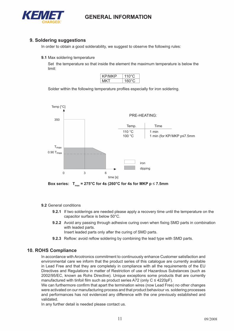
9. Soldering suggestionsIn order to obtain a good solderability, we suggest to observe the following rules:
9.1 Maxsolderingtemperature Set the temperature so that inside the element the maximum temperature is below the limit:
KP/MKP 110°CMKT 160°C
Solder within the following temperature profiles especially for iron soldering.
9.2 General conditions9.2.1 If two solderings are needed please apply a recovery time until the temperature on the capacitor surface is below 50°C. 9.2.2 Avoid any passing through adhesive curing oven when fixing SMD parts in combination with leaded parts. InsertleadedpartsonlyafterthecuringofSMDparts.9.2.3 Reflow: avoid reflow soldering by combining the lead type with SMD parts.
10. rohS ComplianceIn accordance with Arcotronics commitment to continuously enhance Customer satisfaction and environmental care we inform that the product series of this catalogue are currently available in Lead Free and that they are completely in compliance with all the requirements of the EU DirectivesandRegulationsinmatterofRestrictionofuseofHazardousSubstances(suchas2002/95/EC, known as Rohs Directive). Unique exceptions some products that are currently manufactured with tinfoil film such as product series A72 (only C ≤ 4220pF).We can furthermore confirm that apart the termination wires (now Lead Free) no other changes were activated on our manufacturing process and that product behaviour vs. soldering processes and performances has not evidenced any difference with the one previously established and validated.Inanyfurtherdetailisneededpleasecontactus.
PRE-HEATING:
Temp. Time110°C100°C
1min1min(forKP/MKP p≤7.5mm
Box series: tmax = 275°C for 4s (260°C for 4s for mKP p ≤ 7.5mm
09/2008 2
General information
otherS• Any buzzing noise produced by the capacitor is caused by the vibration of the film due to the
Coulomb force that is generated between the electrodes with opposite poles. This buzzing noise becomes louder if a wave-form with a high distortion rate or frequency is applied acrossthecapacitor.Thisbuzzingnoiseisofnodamagetothecapacitor.
• The capacitor modifies its characteristics according to the ambient conditions in which it operates.Innormalconditionsavariationinthecapacitancetakesplaceduetotheamountofhumiditycontainedintheair.Thevariationmainlydependsuponthetypeofdielectricandthematerialusedforthecoating.
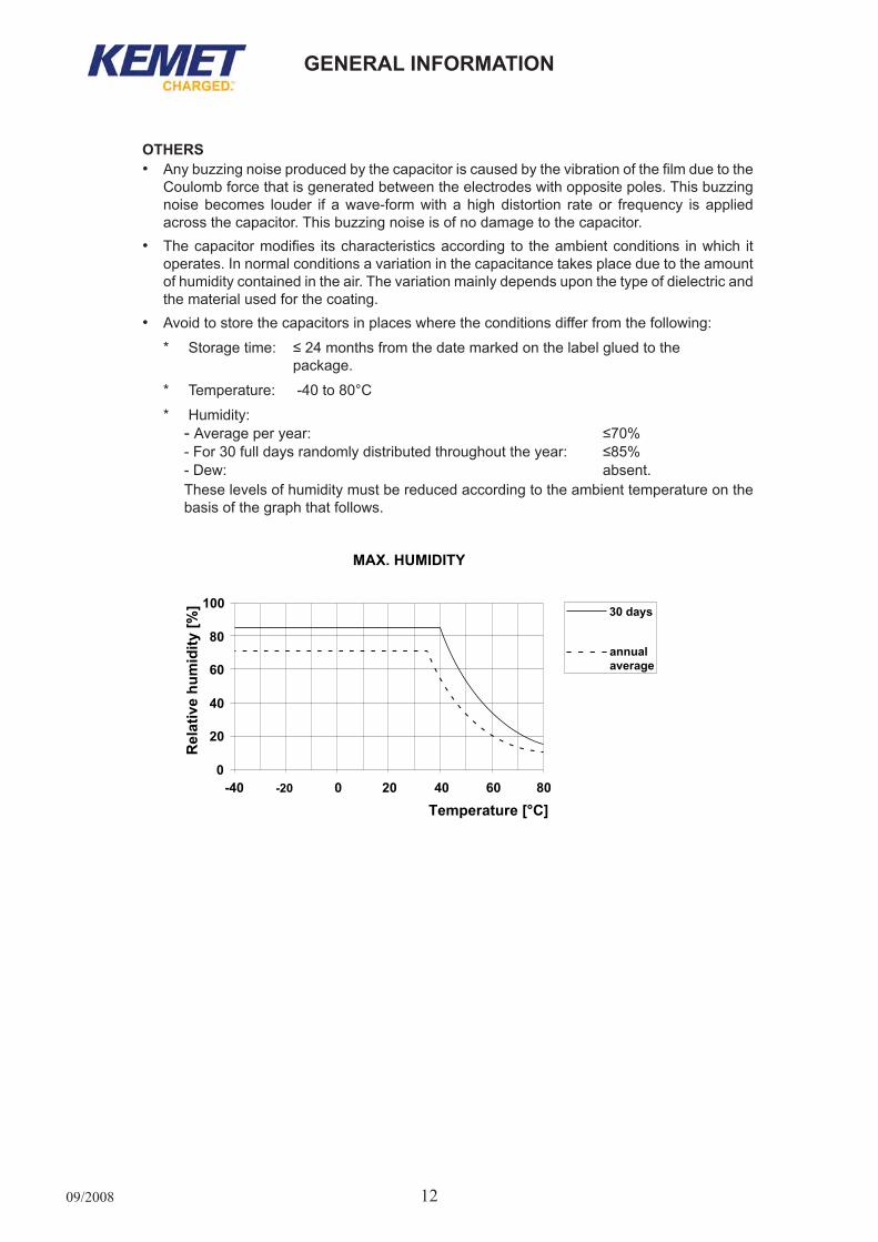
• Avoid to store the capacitors in places where the conditions differ from the following:
* Storage time: ≤ 24 months from the date marked on the label glued to the package.
* Temperature: -40 to 80°C
* Humidity:-Average per year: ≤70%- For 30 full days randomly distributed throughout the year: ≤85%- Dew: absent.Theselevelsofhumiditymustbereducedaccordingtotheambienttemperatureonthebasis of the graph that follows.
09/2008
General information
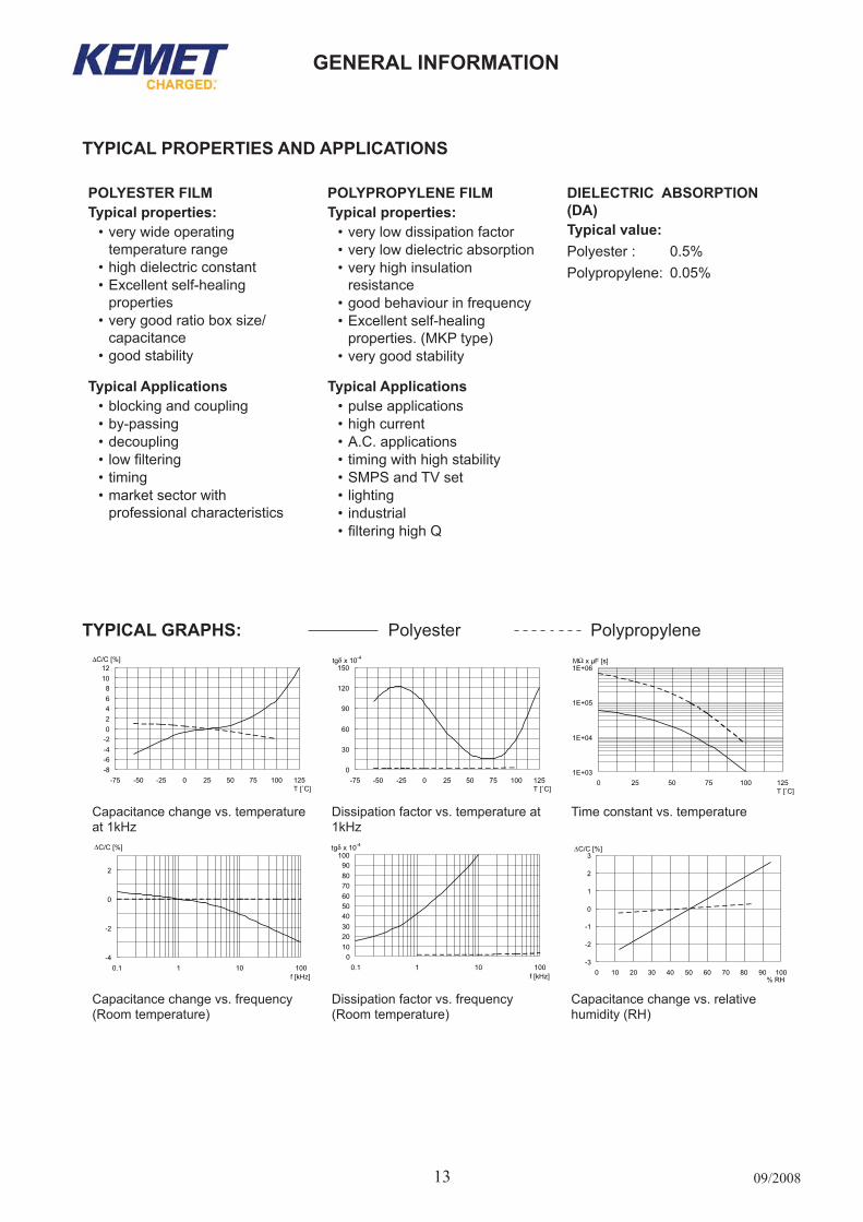
tyPiCal GraPhS: Polyester Polypropylene
Capacitancechangevs.temperatureat1kHz
Dissipationfactorvs.temperatureat1kHz
Timeconstantvs.temperature
Capacitance change vs. frequency (Roomtemperature)
Dissipation factor vs. frequency (Roomtemperature)
Capacitancechangevs.relativehumidity(RH)
tyPiCal ProPertieS anD aPPliCationS
PolyeSter filmtypical properties:
• very wide operating temperaturerange
•highdielectricconstant•Excellentself-healing
properties•verygoodratioboxsize/
capacitance•goodstability
PolyProPylene filmtypical properties:
• very low dissipation factor• very low dielectric absorption•veryhighinsulation
resistance• good behaviour in frequency•Excellentself-healing
properties.(MKPtype)•verygoodstability
DieleCtriC aBSorPtion (Da)typical value:Polyester : 0.5%Polypropylene: 0.05%
typical applications•blockingandcoupling•by-passing•decoupling• low filtering•timing• market sector with
professionalcharacteristics
typical applications•pulseapplications•highcurrent•A.C.applications• timing with high stability•SMPSandTVset•lighting•industrial• filtering high Q

09/2008
General information
ProDUCt CoDe SyStem anD Date CoDe: Box anD axial SerieS
Year Codeletter Month Codeletter1998 K January 11999 L February 22000 M March 32001 N April 42002 P May 52003 R June 62004 S July 72005 T August 82006 U September 92007 V October O2008 W November N2009 X December D2010 A2011 B
Date CoDe (accordingtoEN60062)ProDUCt CoDe SyStemThe part number, comprising 14 digits, is formed as follows:
1 2 3 4 5 6 7 8 9 10 11 12 13 14
-
Digit1to3 Seriescode.
Digit4 d.c.ora.c.ratedvoltage
*AC
==
310Vac50Vdc
IK
==
250Vdc275Vac
PQ
==
630Vdc1000Vdc
UV
==
2000Vdc520Vdc
34
==
300Vac440Vac
DE
==
063Vdc100Vdc
L*M
==
250Vac400Vdc
RS
==
1250Vdc1500Vdc
WX
==
500Vdc450Vdc
*56
==
500Vac600Vac
G = 160Vdc N = 400Vac T = 1600Vdc 2 = 230Vac 7 = 700Vac9 = 900Vac
(*M=420VdcforR71Seriesonly)-(*5=520VacforR475Seriesonly)-(*A=330VacforR49Seriesonly)
Digit5 Pitch(mm)ofradialcapacitorsorlengthofaxialcapacitors(for Polyester, Polypropylene and Suppressor caps)
C = 5.0 F =10/11 I =15/16.5 N = 22.5 R =27.5 W= 37.5D =7.5 H =14 K =20.5 Q = 28.0 T =33.0
Digit 6 to 9 Digits 7 - 8 - 9 indicate the first three digits of Capacitance value and the 6th digit indicates the number of zerosthatmustbeaddedtoobtaintheRatedCapacitanceinpF(for Polyester, Polypropylene and Suppressor caps). Digit6to9 IndicatetheArcotronicsinternalcapacitancecode( for Precision caps).
Digit 10 to 11 Mechanical version and/or packaging: see the pages related to each series.
Digit 12 Identifies the dimensions and electrical characteristics
Digit13 Internaluse.
Digit14 Capacitancetolerance
Codeletter Z D P F A L G H J K MCapacitancetolerance ±1pF 0.5% 0.625% 1% 1.25% 1.5% 2% 2.5% 5% 10% 20%
Code example: r82 Series (Polyester radial) R82 M C 2100 AA 6 0 JR82SeriesVR=400VdcLeadspacing=5mmC=0.01µFLooseversion(4+1.5mm)Dim.&Electr.char.InternaluseTolerance5%

09/2008
General information
NUMbER OF PIECES FOR PACKING UNITD max
(mm)
l max
(mm)
loose*
(pcs)
reelØ 355mm
(pcs) 5 5.1 ... 5.5 5.6 ... 6.5 6.6 ... 7.0 7.1 ... 7.5 7.6 ... 8.0 8.1 ... 9.5 5.0 ... 6.0 6.1 ... 6.5
111111
11.0 ... 16.5 11.0 ... 16.5 11.0 ... 16.5 11.0 ... 16.5 14.0 ... 16.5 14.0 ... 16.5
150015001200175015001250100020002000
30001500130011001000
900800
13001200
5.5 ... 6.0 6.1 ... 6.5 6.6 ... 7.0 7.1 ... 7.5 7.6 ... 8.0 8.1 ... 9.0 9.1 ...10.0 10.1 ...11.5
20.5 20.5 20.5 20.5 20.5 20.5 20.5 20.5
15001250125010001000
750750500
1300120011001000
900800600400
7.0 ... 7.5 7.6 ... 8.0 8.1 ... 9.0 9.1 ...10.0 10.1 ...11.0 11.1 ...13.0 13.1 ...15.0 15.1 ...16.5
28.0 28.0 28.0 28.0 28.0 28.0 28.0 28.0
750500500500500300300300
1000900800600400400300250
°*Loose version: lead length = 40±5mm
leaD taPinG anD PaCKaGinGleaD taPinG anD PaCKaGinG of axial ComPonentS for aUtomatiC anD roBot inSertion maChineS
Technical terms: IEC 60286-1
Description Symbol Dimensions (mm)
Componentdiameter D 4.5...19.5Bodylength L 11...33Componentpitch A* SeetableIReelcorediameter E 85Arborholediameter M 30Reeldiameter Ø 355max.Tape width H 6±0.5/9±1**Bodylocation(lateraldeviation) G ≤0.7Bodylocation(longitudinaldeviation) N ≤1.2Tapespacing B SeeTableIILeadlengthfromthecomponentbodytotheadhesivetape I ≥20
Distance between reel flanges C SeetableII
Remarks*Cumulativepitchtolerancemustnotexceed1.5mmoversixconsecutivecomponents.**9±1 for capacitor with L≥31.5
TableID max(mm)
a(mm)
≤ 505.1...09.509.6...14.714.8...19.5
5±0.5 10±0.5
15±0.5
20±1.0
TableIIl max(mm) Class B±1.5
(mm)C
(mm)
≤114.0...20.5
RSB
26
IIIIII
52.463.673.0
758698
NUMbER OF PIECES FOR PACKING UNITD max
(mm)
l max
(mm)
loose*
(pcs)
reelØ 355mm
(pcs) 10.0 ... 11.5 11.6 ... 13.0 13.1 ... 15.0 15.1 ... 16.5 16.6 ... 18.0 18.1 ... 20.0 20.1 ... 26.4
33.033.033.033.033.033.033.0
400300300200200150100
400400300250200150
*Loose version: lead length = 40±5mm
Packaging detailAvailablereelØ355mmonly.reel

09/2008
General information
Box dimensions Pitch loose*short*leads
loose**long**leads
ammo reel Ø355mmB h l
(mm) (mm) (mm) (mm) (pcs) (pcs) (pcs) (pcs)3.0 8.0 10.0 7.5 1500 1750 2800 21004.0 9.0 10.0 7.5 2000 1500 2100 15005.0 10.5 10.0 7.5 1500 1000 1600 12006.0 12.0 10.5 7.5 1000 800 1350 1000
Description Symbol
Dimensions (mm)
Pitchtol.
5 mm 7.5 mm 7.5 mmfig.1 fig.1 fig. 2
Lead wire diameter d 0.5...0.6 0.5...0.6 0.5...0.6 ±0.05
Tapingpitch P 12.7 12.7 12.7 ±1
Feedholepitch P0 12.7 12.7 12.7 ±0.2*Centeringoftheleadwire P1 3.85 2.6 3.75 ±0.7
Centeringofthebody P2 6.35 6.35 ±1.3
Leadspacing(pitch) F 5 7.5 7.5 +0.6 -0.1
Componentalignment ∆h 0 0 0 ±2Heightofcomponentfromtapecenter H** 18.5 18.5 18.5 ±0.5
Carrier tape width W 18 18 18 +1 -0.5
Hold down tape width W0 6 6 6 min.
Holeposition W1 9 9 9 ±0.5
Hold down tape position W2 3 3 3 max.
Feedholediameter D0 4 4 4 ±0.2
Tapethickness t 0.7 0.7 0.7 ±0.2
leaD taPinG anD PaCKaGinG of raDial ComPonentS for aUtomatiC inSertion maChineSTechnical terms: IEC 60286-2
Remarks* Max1mmon20pitches** H = 16.5 mm is available upon request.For orders of capacitors with pitch = 7.5 mm, please specify the requested version (fig.1 or fig.2).
NUMbER OF PIECES FOR PACKING UNITBox dimensions Pitch loose
*short*leads
loose**long**leads
ammo reel Ø355mmB h l
(mm) (mm) (mm) (mm) (pcs) (pcs) (pcs) (pcs)2.5 6.5 7.2 5.0 3000 4000 3500 25003.5 7.5 7.2 5.0 2000 3000 2500 18004.5 9.5 7.2 5.0 1500 2000 1900 14005.0 10.0 7.2 5.0 1000 1500 1700 12006.0 11.0 7.2 5.0 2000 1000 1400 10007.2 13.0 7.2 5.0 1500 750 1150 800
* Short leads: lead length =04+1.5 mm (pitch = 5mm); 4+2 mm(pitch=7.5mm)** Long leads: lead length = 17+1/-2mm
Packaging detailTwo different containers are available: Fan-foldbox(Ammo-pack)ReelØ355mmonly.
Pitch=5and7.5mm Pitch=7.5mm
reel(dimensionsinmm)
ammo-pack(dimensionsinmm)
Fig.1 Fig.2
* Lower dimension available* upon request (max. 295mm)
09/2008
General information
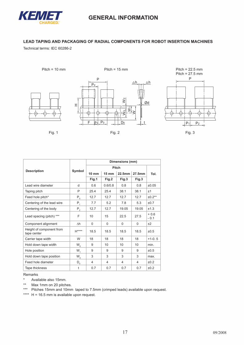
Description Symbol
Dimensions (mm)
Pitch
tol.10 mm 15 mm 22.5mm 27.5mmfig.1 fig.2 fig.3 fig.3
Lead wire diameter d 0.6 0.6/0.8 0.8 0.8 ±0.05
Tapingpitch P 25.4 25.4 38.1 38.1 ±1
Feedholepitch* P0 12.7 12.7 12.7 12.7 ±0.2**
Centering of the lead wire P1 7.7 5.2 7.8 5.3 ±0.7
Centeringofthebody P2 12.7 12.7 19.05 19.05 ±1.3
Leadspacing(pitch)*** F 10 15 22.5 27.5 + 0.6 -0.1
Componentalignment ∆h 0 0 0 0 ±2
Heightofcomponentfromtapecenter H**** 18.5 18.5 18.5 18.5 ±0.5
Carrier tape width W 18 18 18 18 +1-0. 5
Hold down tape width W0 9 10 10 10 min.
Holeposition W1 9 9 9 9 ±0.5
Hold down tape position W2 3 3 3 3 max.
Feedholediameter D0 4 4 4 4 ±0.2
Tapethickness t 0.7 0.7 0.7 0.7 ±0.2
Remarks* Availablealso15mm.** Max1mmon20pitches.*** Pitches 15mm and 10mm taped to 7.5mm (crimped leads) available upon request.**** H = 16.5 mm is available upon request.
leaD taPinG anD PaCKaGinG of raDial ComPonentS for roBot inSertion maChineSTechnical terms: IEC 60286-2
Pitch=10mm Pitch=15mm Pitch=22.5mmPitch=27.5mm
Fig.1 Fig.2 Fig.3
P
P1
P2
P0F D0
H
W0
W2
W1
W
h h
t
Ød
P
P1 P2
09/2008 8
General information
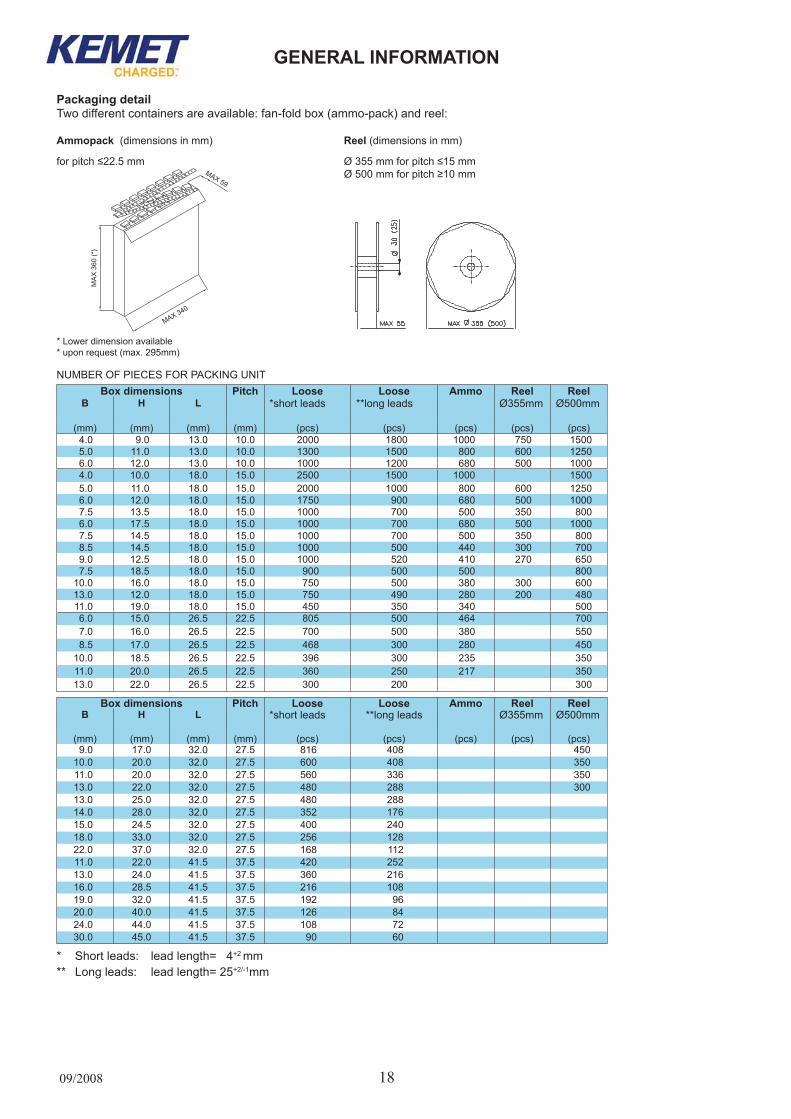
NUMbER OF PIECES FOR PACKING UNITBox dimensions Pitch loose loose ammo reel reel
B h l *shortleads **longleads Ø355mm Ø500mm
(mm) (mm) (mm) (mm) (pcs) (pcs) (pcs) (pcs) (pcs)4.0 9.0 13.0 10.0 2000 1800 1000 750 15005.0 11.0 13.0 10.0 1300 1500 800 600 12506.0 12.0 13.0 10.0 1000 1200 680 500 10004.0 10.0 18.0 15.0 2500 1500 1000 15005.0 11.0 18.0 15.0 2000 1000 800 600 12506.0 12.0 18.0 15.0 1750 900 680 500 10007.5 13.5 18.0 15.0 1000 700 500 350 8006.0 17.5 18.0 15.0 1000 700 680 500 10007.5 14.5 18.0 15.0 1000 700 500 350 8008.5 14.5 18.0 15.0 1000 500 440 300 7009.0 12.5 18.0 15.0 1000 520 410 270 6507.5 18.5 18.0 15.0 900 500 500 800
10.0 16.0 18.0 15.0 750 500 380 300 60013.0 12.0 18.0 15.0 750 490 280 200 48011.0 19.0 18.0 15.0 450 350 340 5006.0 15.0 26.5 22.5 805 500 464 7007.0 16.0 26.5 22.5 700 500 380 5508.5 17.0 26.5 22.5 468 300 280 450
10.0 18.5 26.5 22.5 396 300 235 35011.0 20.0 26.5 22.5 360 250 217 35013.0 22.0 26.5 22.5 300 200 300
Box dimensions Pitch loose loose ammo reel reel B h l *shortleads **longleads Ø355mm Ø500mm
(mm) (mm) (mm) (mm) (pcs) (pcs) (pcs) (pcs) (pcs)9.0 17.0 32.0 27.5 816 408 450
10.0 20.0 32.0 27.5 600 408 35011.0 20.0 32.0 27.5 560 336 35013.0 22.0 32.0 27.5 480 288 30013.0 25.0 32.0 27.5 480 28814.0 28.0 32.0 27.5 352 17615.0 24.5 32.0 27.5 400 24018.0 33.0 32.0 27.5 256 12822.0 37.0 32.0 27.5 168 11211.0 22.0 41.5 37.5 420 25213.0 24.0 41.5 37.5 360 21616.0 28.5 41.5 37.5 216 10819.0 32.0 41.5 37.5 192 9620.0 40.0 41.5 37.5 126 8424.0 44.0 41.5 37.5 108 7230.0 45.0 41.5 37.5 90 60
* Short leads: lead length= 04+2 mm ** Long leads: lead length= 25+2/-1mm
Packaging detailTwo different containers are available: fan-fold box (ammo-pack) and reel:
ammopack(dimensionsinmm) reel (dimensionsinmm)
for pitch ≤22.5 mm Ø 355 mm for pitch ≤15 mm Ø 500 mm for pitch ≥10 mm
* Lower dimension available* upon request (max. 295mm)