1 INTRODUCTION TO PICAXE · PDF file1 INTRODUCTION TO THE PICAXE SYSTEM ... alarm systems,...
34
1 INTRODUCTION TO THE PICAXE SYSTEM revolution © copyright 2001-12 Revolution Education Lt v1.2 Web: www.picaxe.com INTRODUCTION TO THE PICAXE SYSTEM A PIC microcontroller is often described as a ‘computer-on-a-chip’. It is an integrated circuit that contains memory, processing units, and input/output circuitry in a single unit. Microcontrollers are purchased ‘blank’ and then programmed with a specific control program. Once programmed the microcontroller is build into a product to make the product more intelligent and easier to use. As an example, a microwave oven may use a single microcontroller to process information from the keypad, display user information on the seven segment display, and control the output devices (turntable motor, light, bell and magnetron). One microcontroller can often replace a number of separate parts, or even a complete electronic circuit. Some of the advantages of using microcontrollers in a product design are: • increased reliability through a smaller part count • reduced stock levels, as one microcontroller replaces several parts • simplified product assembly and smaller end products • greater product flexibility and adaptability since features are programmed into the microcontroller and not built into the electronic hardware • rapid product changes or development by changing the program and not the electronic hardware Applications that use microcontrollers include household appliances, alarm systems, medical equipment, vehicle subsystems, and electronic instrumentation. Some modern cars contain over thirty microcontrollers - used in a range of subsystems from engine management to remote locking! In industry microcontrollers are usually programmed using the assembler or ‘C’ programming languages. However the complexity of these languages means that it is not realistic for younger students to be able to successfully use these languages within KS3 or 4 coursework.
Transcript of 1 INTRODUCTION TO PICAXE · PDF file1 INTRODUCTION TO THE PICAXE SYSTEM ... alarm systems,...

1
INTRODUCTION TO THE PICAXE SYSTEM
revolution © copyright 2001-12 Revolution Education Lt v1.2 Web: www.picaxe.com
������������
�����
����
��������
��
������
�
����
���
INTRODUCTION TO THE
PICAXE SYSTEM
A PIC microcontroller is often
described as a ‘computer-on-a-chip’.
It is an integrated circuit that contains
memory, processing units, and input/output
circuitry in a single unit.
Microcontrollers are purchased ‘blank’ and then programmed with a specific control
program. Once programmed the microcontroller is build into a product to make the
product more intelligent and easier to use.
As an example, a microwave oven may use a single microcontroller to
process information from the keypad, display user information on
the seven segment display, and control the output devices
(turntable motor, light, bell and magnetron).
One microcontroller can often replace a number of
separate parts, or even a complete electronic circuit.
Some of the advantages of using microcontrollers in a
product design are:
• increased reliability through a smaller part count
• reduced stock levels, as one microcontroller replaces
several parts
• simplified product assembly and smaller end products
• greater product flexibility and adaptability since features are programmed
into the microcontroller and not built into the electronic hardware
• rapid product changes or development by changing the program and not the
electronic hardware
Applications that use microcontrollers include household appliances, alarm systems,
medical equipment, vehicle subsystems, and electronic instrumentation. Some modern
cars contain over thirty microcontrollers - used in a range of subsystems from engine
management to remote locking!
In industry microcontrollers are usually programmed using the assembler or ‘C’
programming languages. However the complexity of these languages means that it is not
realistic for younger students to be able to successfully use these languages within KS3 or
4 coursework.

2
INTRODUCTION TO THE PICAXE SYSTEM
revolution © copyright 2001-12 Revolution Education Lt v1.2 Web: www.picaxe.com
THE PICAXE SYSTEM
The ‘PICAXE’ system is an easy-to-program microcontroller system that uses a simple
BASIC language, which most students can learn very quickly. The PICAXE system
exploits the unique characteristics of the new generation of low-cost ‘FLASH’ memory
based microcontrollers. These microcontrollers can be programmed over and over again
without the need for an expensive PIC programmer.
The power of the PICAXE system is its simplicity. No programmer, eraser
or complicated electronic system is required - the microcontroller is programmed (with a
simple ‘BASIC’ program or flowchart) via a 3-wire connection to the computers serial
port. The operational PICAXE circuit uses just 3 components and can be easily
constructed on a prototyping breadboard, strip-board or PCB design.
The main features of the PICAXE system are as follows:
• low-cost, simple to construct circuit
• multiple inputs, outputs and analogue channels
• rapid download via USB cable
• free, easy to use Programming Editor software
• simple to learn BASIC language
• extensive free manuals and online support forum
�����
���������� �
�
�
�
�
�
�
�
�
��
����
���������
�
��
�����
�����

3
INTRODUCTION TO THE PICAXE SYSTEM
revolution © copyright 2001-12 Revolution Education Lt v1.2 Web: www.picaxe.com
TUTORIAL 1 – THE PICAXE SYSTEM
The PICAXE system consists of three main components:
The ‘Programming Editor’ software
This software runs on a computer and allows you to use the computer keyboard to type
in programs in a simple BASIC language. Programs can also be generated by drawing
flowcharts. Alternately the ‘Logicator’ software may be used to simulate complete
electronic circuits, programmed via flowcharts.
The AXE027 USB Cable
This is the cable that connects the computer to the PICAXE system. The cable only
needs to be connected when downloading programs. It does not have to be connected
when the PICAXE is running because the program is permanently stored on the
PICAXE chip – even when the power supply is removed!
Power Supply
Use battery packs (3xAA cell = 4.5V is
recommended) or a regulated 5V DC power
supply only.
The PICAXE chip and board
The PICAXE microcontroller chip ‘runs’
program that have been downloaded to it.
However the chip needs to be mounted on
an electronic board that provide connection
to the microcontroller chip.
The electronic board can be designed by the
user on a piece of stripboard or printed
circuit board, or a pre-made interface or tutorial board may be used for speed and
convenience. This course presumes use of a PICAXE-18M2 (18 pin) microcontroller
mounted on the tutorial board.
Summary - Programming Procedure
1. Write the program on the computer using the Programming Editor software.
2. Connect the download cable from the computer to the PICAXE.
3. Connect the battery pack to the PICAXE.
4. Use the Programming Editor software to download the program. The download
cable can then be removed after the download.
The program will start running on the PICAXE automatically. However the program can
also be restarted at any time by pressing the reset switch.
��������������� �
�
�
�
�
�
�
�
�
��
����
��
���
���
��
�� ���
��
�����
�
�
�
�
�
�
�
�
!"�#�$�
%&'()��

4
INTRODUCTION TO THE PICAXE SYSTEM
revolution © copyright 2001-12 Revolution Education Lt v1.2 Web: www.picaxe.com
PICAXE-18 Boards
Three main types of PICAXE18 project / tutorial boards are available
Tutorial Board (AXE049)
This is a tutorial board containing switches, sensors, a seven segment display and
output drivers. This is the board described in these notes.
Standard Project Board (CHI030)
This is a project board that provides 8 digital (on/off) outputs via a darlington driver
IC.
High Power Project Board (CHI035)
This is a project that provides 4 digital outputs (via FET drivers) and 2 reversible motor
outputs.
���
�
�
�
�
#
�
�
�
�
���
�
�
$
#
�
�
�
�
�
� ��� � ���
���
*+,+ -.
*+,+ -�
�
�
�
�
�
���
�
�
�
�
#
�
�
�
�
��������������� �
�
�
�
�
�
�
�
�
��
����
��
���
���
��
�� ���
��
�����
�
�
�
�
�
�
�
�
!"�#�$�
%&'()��

5
INTRODUCTION TO THE PICAXE SYSTEM
revolution © copyright 2001-12 Revolution Education Lt v1.2 Web: www.picaxe.com
Preparing the Tutorial Board
As supplied new, the tutorial board requires the battery clip to be connected before
use.
Battery BoxLocate the battery clip, and fold the bare wire back over the insulation on each wire.
Place the red wire in the socket marked ‘V+’ and the black wire in the socket marked
‘0V’. Tighten the screw so that the insulation and bare wire are both trapped in the
socket – this provides a stronger joint than just trapping the bare wire.
Always use the 4.5V battery box (3 AA cells required) with the tutorial board. DO NOT
use a 9V PP3 battery.
Solder ResistThe tutorial board is manufactured using a wave soldering technique. To prevent solder
sticking to the spare holes (for optional components) a ‘peelable solder resist’ layer is
printed on the base of the board. This peelable resist must be peeled off before the
optional components may be soldered in place.

6
INTRODUCTION TO THE PICAXE SYSTEM
revolution © copyright 2001-12 Revolution Education Lt v1.2 Web: www.picaxe.com
Downloading a Sample Program
The following program switches output 7 on and off every second. When you
download this program the decimal point on the seven segment display on the
tutorial board should flash on and off every second.
main:
high B.7
pause 1000
low B.7
pause 1000
goto main
This program uses the high and low commands to control output pin 7, and uses the
pause command to make a delay (1000 ms = 1 second).
The last goto main command makes the program ‘jump’ back to the label main: at the
start of the program. This means the program loops forever. Note that the first time the
label is used it must be followed by the colon (:) symbol. This tells the computer the
word is a new label.
Detailed instructions:
1. Connect the PICAXE cable to the computer serial port. Note which port it is
connected to.
1. Start the Programming Editor software.
2. Select View>Options to select the Options screen (this may automatically appear).
3. Click on the ‘Mode’ tab and select PICAXE-18M2
4. Click on the ‘Serial Port’ tab and select the serial port that the PICAXE cable is
connected to. Click ‘OK’
5. Type in the following program:
main:
high B.7
pause 1000
low B.7
pause 1000
goto main
(NB note the colon (:) directly after the label ‘main’ and the spaces between the
commands and numbers)
6. Make sure the PICAXE circuit is connected to the serial cable, and that the batteries
are connected (4.5V recommended).
7. Select PICAXE>Run. A download bar should appear as the program downloads.
When the download is complete the program should start running automatically –
the decimal point LED on output 7 should flash on and off every second.
7
INTRODUCTION TO THE PICAXE SYSTEM
revolution © copyright 2001-12 Revolution Education Lt v1.2 Web: www.picaxe.com
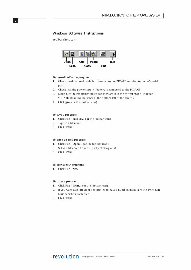
Windows Software Instructions
Toolbar short-cuts:
To download/run a program:1. Check the download cable is connected to the PICAXE and the computer’s serial
port
2. Check that the power supply / battery is connected to the PICAXE
3. Make sure the Programming Editor software is in the correct mode (look for
‘PICAXE-18’ in the statusbar at the bottom left of the screen).
4. Click Run (or the toolbar icon)
To save a program:1. Click File - Save As... (or the toolbar icon)
2. Type in a filename
3. Click <OK>
To open a saved program:1. Click File - Open... (or the toolbar icon)
2. Select a filename from the list by clicking on it
3. Click <OK>
To start a new program:1. Click File - New
To print a program:1. Click File - Print... (or the toolbar icon)
2. If you want each program line printed to have a number, make sure the ‘Print Line
Numbers’ box is checked
3. Click <OK>

8
INTRODUCTION TO THE PICAXE SYSTEM
revolution © copyright 2001-12 Revolution Education Lt v1.2 Web: www.picaxe.com
TUTORIAL 2 - USING SYMBOLS
Sometimes it can be hard to remember which pins are connected to which devices. The
‘symbol’ command can then be used at the start of a program to rename the inputs and
outputs. Note this program assumes connection of an external buzzer to output pin 1.
symbol dp = 7 ‘ rename output7 ‘dp’ (decimal point)
symbol buzzer = 1 ‘ rename output1 ‘buzzer’
main: ‘ make a label called ‘main’
high dp ‘ LED on
low buzzer ‘ buzzer off
wait 1 ‘ wait 1 second
low dp ‘ LED off
high buzzer ‘ buzzer on
wait 1 ‘ wait 1 second
goto main ‘ jump back to the start
Remember that comments (an explanation after the apostrophe (‘) symbol) can make
each line of a program much easier to understand. These comments are ignored by the
computer when it downloads a program to the PICAXE
A label (e.g. main: in the program above) can be any word (apart from keywords such as
‘switch’), but must begin with a letter. When the label is first defined it must end with a
colon (:). The colon ‘tells’ the computer that the word is a new label.
This program uses the wait command. The commands wait and pause both create time
delays. However wait can only be used with whole seconds, pause can be used for
shorter time delays (measured in milliseconds (1000th of a second)).
Wait can be followed by a number between 1 and 65.
Pause can be followed by a number between 1 and 65535.
It is also a good programming technique to use tabs (or spaces) at the start of lines
without labels so that all the commands are neatly aligned. The term ‘white-space’ isused by programmers to define tabs, spaces and blank lines, and the correct use of white-
space can make the program listing much easier to read and understand.
Note:Some early BASIC languages used ‘line numbers’ rather than labels for ‘goto’
commands. Unfortunately this line number system can be inconvenient to use, because
if you modify your program by later adding, or removing, lines of code you then have to
modify all the line numbers within the ‘goto’ commands accordingly. The label system,
as used in most modern BASIC languages, overcomes this problem automatically.

9
INTRODUCTION TO THE PICAXE SYSTEM
revolution © copyright 2001-12 Revolution Education Lt v1.2 Web: www.picaxe.com
The ‘brain’ of the PICAXE system is the 18 pin PICAXE18M2 microcontroller. Although
microcontrollers are relatively cheap (some microcontrollers cost less than £1)
microcontrollers are very complex devices containing many thousands of transistors,
resistors and other electronic components.
The PICAXE microcontroller stores it’s program in non-volatile FLASH memory. This
means it does not loose the program when the power is removed from the circuit – when
the battery is re-connected the program will start again. However when you wish to
reprogram the PICAXE a new program can be downloaded – this erases the old program
and writes the new program into the memory. Only one program can be in memory at
one time.
Note that is not possible to ‘read’ the program back out of the PICAXE memeory.
Therefore you must save the program on the computer (before it is downloaded) if you
wish to keep your program to use in the future.
Aswell as the program ROM memory (Read Only Memory) the microcontroller also
contains temporary RAM (Random Access memory).
RAM (Random Access Memory) is ‘temporary’ memory used for storing information
whilst the program is running. This is normally used to store answers to mathematical
‘sums’ the microcontroller carries out as it is working. This memory is ‘volatile’, which
means that as soon as the power is disconnected the contents of the memory is lost.
There are 28 bytes of temporary memory that can be used within programs, and these
are labelled b0 to b27 within programs.

10
INTRODUCTION TO THE PICAXE SYSTEM
revolution © copyright 2001-12 Revolution Education Lt v1.2 Web: www.picaxe.com
The PICAXE-18 Circuit
The basic PICAXE-18 circuit is shown below.
The 4k7 resistor is used to pull the PICAXE microcontrollers reset pin (pin 4) high. If
desired, a reset switch can also be connected between the reset pin (pin 4) and 0V. When
the switch is pushed the PICAXE microcontroller ‘resets’ to the first line in the program.
The PICAXE-18M2 microcontroller
Please note that the PICAXE microcontroller is not a blank microcontroller! The
PICAXE microcontroller is pre-programmed with a bootstrap program that enables the
direct cable download. Blank microcontrollers will not contain this bootstrap program
and so cannot be programmed from within the PICAXE system
��
��
���
/
�
�
�
#
$
�
�
/
0
#)�
!1!,
$�
��
1! 2'&-+3,
1! 2'&-24��)
��)
���
���
�/
��
��
�$
�#
��
��
��
��
24-�
+3,-�
+3,-�
+3,-�
+3,-�
24-�
24-�
24-�
24-�
+3,-�
+3,-�
+3,-$
+3,-#
� � �

11
INTRODUCTION TO THE PICAXE SYSTEM
revolution © copyright 2001-12 Revolution Education Lt v1.2 Web: www.picaxe.com
The PICAXE computer interface circuit
The PICAXE system uses a very simple interface to the computer serial port. Although
this interface does not use true RS232 voltages, it is very low-cost and has proved to work
reliably on almost all modern computers.
It is strongly recommended that this interfacing circuit is included on every PCB
designed to be used with the PICAXE microcontroller. This enables the PICAXE
microcontroller to be re-programmed without removing from the PCB.
Note:Most modern computers have two serial ports, normally labelled COM1 and COM2. The
Programming Editor software must be configured for the correct port – select
View>Options>Serial Port to select the correct serial port for your machine.
�����
1! 2'&-+3,-�-524-�1! 2'&-24-�-524-���-�-524-$��)
��)
���
���
� � �

12
INTRODUCTION TO THE PICAXE SYSTEM
revolution © copyright 2001-12 Revolution Education Lt v1.2 Web: www.picaxe.com
TUTORIAL 3 - FOR…NEXT LOOPS
It is often useful to repeat the same part of a program a number of times, for instance
when flashing a LED. In these cases a for…next loop can be used.
This program flashes the LED connected to output pin 7 on and off 15 times. The
number of times the code has been repeated is stored in the RAM memory of the
PICAXE chip using variable b0 (the PICAXE contains 14 general purpose byte variables
labelled b0 to b13). These variables can also be renamed using the symbol command to
make them easier to remember.
symbol counter = b0 ‘ define the variable “counter”
symbol dp = B.7 ‘ define pin B.7 with the name “dp”
main: for counter = 1 to 15 ‘ start a for...next loop
high dp ‘ switch pin 7 high
pause 500 ‘ wait for 0.5 second
low dp ‘ switch pin 7 low
pause 500 ‘ wait for 0.5 second
next counter ‘ end of for...next loop
end ‘ end program
Note again how white-space (extra spaces) has been used to clearly show all the
commands that are contained between the for and next commands.

13
INTRODUCTION TO THE PICAXE SYSTEM
revolution © copyright 2001-12 Revolution Education Lt v1.2 Web: www.picaxe.com
��������������� �
�
�
�
�
�
�
�
�
��
����
��
���
���
��
�� ���
��
�����
1+&' -*+,+
�
�
�
�
�
�
�
�
Controlling the speed of a motor
As the PICAXE system operates very quickly, it is possible to control the speed of motors
by switching them on and off very quickly. This type of control is known as Pulse Width
Modulation (PWM). PWM is a good control technique because it allows the motors to
work at a low speed whilst still maintaining a high torque (“turning force”). PWM is
often used, for instance to control the speed of an electric drill or screwdriver. For PWM
to work correctly you need a high quality motor. These programs are designed for a
‘solar’ motor and may not work correctly with a cheap toy motor.
symbol mark1 = b6 ‘ rename variables - easier to remember
symbol space1 = b7
symbol mark2 = b8
symbol space2 = b9
let mark1 = 2 ‘ preload mark1 / space1 with ratio 2:10 (1:5)
let space1 = 10
let mark2 = 20 ‘ preload mark2 / space2 with ratio 20:10 (2:1)
let space2 = 10
main:
for b2 = 1 to 200 ‘ start a for...next loop
high B.0 ‘ motor on
pause mark1 ‘ wait mark1 time
low B.0 ‘ motor off
pause space1 ‘ wait space1 time
next b2 ‘ next loop
pause 2000 ‘ stop motor for 2 seconds
for b2 = 1 to 200 ‘ start a for...next loop
high B.0 ‘ motor on
pause mark2 ‘ wait mark2 time
low B.0 ‘ motor off
pause space2 ‘ wait space2 time
next b2 ‘ next loop
pause 2000 ‘ stop motor for 2 seconds
goto main

14
INTRODUCTION TO THE PICAXE SYSTEM
revolution © copyright 2001-12 Revolution Education Lt v1.2 Web: www.picaxe.com
TUTORIAL 4 - BUZZERS AND PIEZO-SOUNDERS
Buzzers will make a noise when they are connected to a power supply. This noise is
usually ‘fixed’ at one frequency and so buzzers can only make one ‘tone’. Piezo-sounders
use a different type of system to create noises, and can be used to create noises of
different tones by providing them with a ‘pulsed’ output.
The PICAXE system can automatically create noises of different frequencies by use of the
sound command.
main:
sound 6,(50,100) ‘ make a sound on 6, freq 50, length 100
sound 6,(100,100) ‘ make a sound on 6, freq 100, length 100
sound 6,(120,100) ‘ make a sound on 6, freq 120, length 100
pause 1000 ‘ wait 1 second
goto main ‘ loop back to start
To test this program you must add a piezo sounder (not supplied, part number SPE002)
to the tutorial board. To do this solder the red wire to the hole marked ‘+’ and the black
wire to the hole marked ‘-‘ under the word PIEZO in the centre of the board.
The first number provides the pin number (on the tutorial board output pin 6 is used).
The next number is the tone, followed by the duration. The higher the tone number the
higher pitch the sound (note that some sounders cannot produce very high tones and so
number greater than 127 may not be heard).
��������������� �
�
�
�
�
�
�
�
�
��
����
��
���
���
��
�� ���
��
�����
%366! !"-7�8
%&'()-7�8
�
�
�
�
�
�
�
�
��������������� �
�
�
�
�
�
�
�
�
��
����
��
���
���
��
�� ���
��
�����
!"-7�8
%&'()-7�8
�
�
�
�
�
�
�
�

15
INTRODUCTION TO THE PICAXE SYSTEM
revolution © copyright 2001-12 Revolution Education Lt v1.2 Web: www.picaxe.com
The following program uses a for…next loop to produce 120 different sounds.
main:
for b0 = 1 to 120 ‘ start a for...next loop
sound B.6,(b0,50) ‘ make a sound , freq value from b0
next b0 ‘ next loop
end
The number stored in variable b0 increase by 1 in every loop (1-2-3 etc.) Therefore by
using the variable name b0 in the tone position, the note can be changed on each loop.
The following program does the same task but backwards.
main:
for b0 = 120 to 1 step -1 ‘ start a for...next loop
‘ (counting down)
sound B.6,(b0,50) ‘ make a sound freq value from b0
next b0 ‘ next loop
end
This next program will give out all 256 possible sounds
main:
sound B.6,(b0,50) ‘ make a sound
let b0 = b0 + 1 ‘ add 1 to the varaible value
goto main ‘ loop again
In this case the program loops forever. However it is important to understand how the
PICAXE performs mathematics.
The PICAXE only understands byte numbers, that is whole numbers between 0 and 255.
It cannot understand fractions and cannot work with negative numbers or numbers
bigger than 255. Therefore if you try to add one to 255 the number will overflow back to
0. Therefore, in the program above, the value in variable b0 will go 252-253-254-255-0-
1-2 etc. as the program loops.

16
INTRODUCTION TO THE PICAXE SYSTEM
revolution © copyright 2001-12 Revolution Education Lt v1.2 Web: www.picaxe.com
��
$�
�2*!
�+&
,'9!
TUTORIAL 5 – USING INPUTS
Digital Sensors
A digital sensor is a simple ‘switch’ type sensor that can only be ‘on’ or ‘off’.
Common examples of a digital sensor are:
• microswitches
• push and rocker switches
• reed switches
The tutorial board has two push switches connected to inputs 6 and 7. Another two
switches can be connected to the input positions 0 and 1 if desired.
��������������� �
�
�
�
�
�
�
�
�
��
����
��
���
���
��
�� ���
��
�����
"292,'&1:2,(;
�
�
�
�
�
�
�
�

17
INTRODUCTION TO THE PICAXE SYSTEM
revolution © copyright 2001-12 Revolution Education Lt v1.2 Web: www.picaxe.com
��
$�
�2*!
�+&
,'9!
"' )
&29;,
This program below shows how to react to switch pushes . In this program output pin
7 flashes every time the push switch on input pin 6 is pushed.
main: ‘ make a label called ‘main’
if pinC.6 = 1 then flash‘ jump if the input is on
goto main ‘ else loop back around
flash: ‘ make a label called ‘flash’
high B.7 ‘ switch output 7 on
pause 2000 ‘ wait 2 seconds
low B.7 ‘ switch output 7 off
goto main ‘ jump back to start
In this program the first three lines make up a continuous loop. If the input is off the
program just loops around time and time again.
If the switch is then pushed the program jumps to the label called ‘flash’. The program
then flashes output 7 on for two seconds before returning to the main loop.
Note carefully the spelling in the if…then line – pinC.6 is all one word (without a
space). Note also that only the label is placed after the command then – no other
words apart from a label are allowed.
Analogue Sensors
An analogue sensor measures a continuous signal such as light, temperature or position.
The analogue sensor provides a varying voltage signal. This voltage signal can be
represented by a number in the range 0 and 255 (e.g. very dark = 0, bright light = 255).
Common examples of analogue sensors are:
• LDR (Light Dependant Resistor)
• Thermistor
• Variable Resistor (potentiometer)
The tutorial board has an LDR mounted on the board, connected to input 2.
18
INTRODUCTION TO THE PICAXE SYSTEM
revolution © copyright 2001-12 Revolution Education Lt v1.2 Web: www.picaxe.com
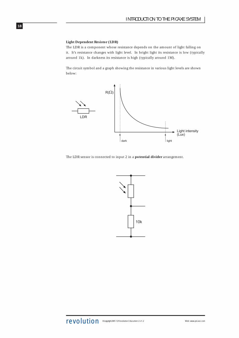
Light Dependent Resistor (LDR)The LDR is a component whose resistance depends on the amount of light falling on
it. It’s resistance changes with light level. In bright light its resistance is low (typically
around 1k). In darkness its resistance is high (typically around 1M).
The circuit symbol and a graph showing the resistance in various light levels are shown
below:
The LDR sensor is connected to input 2 in a potential divider arrangement.
�7�8
�29;,-24,!412,<7�3=8
"' ) &29;,
��
��)

19
INTRODUCTION TO THE PICAXE SYSTEM
revolution © copyright 2001-12 Revolution Education Lt v1.2 Web: www.picaxe.com
Reading Analogue Input Channels
The value of an analogue input can be easily copied into a variable by use of the
‘readadc’ command. The variable value (0 to 160) can then be tested. The following
program switches on one LED if the value is greater than 120 and a different LED if the
value is less than 70. If the value is between 70 and 120 both LEDS are switched off.
main: ‘ make a label called ‚main
readadc C.2,b0 ‘ read channel 2 into variable b0
if b0 > 120 then top ‘ if b0 > 120 then do top
if b0 < 70 then bot ‘ if b0 < 70 then do bot
low B.1 ‘ else switch off 1
low B.2 ‘ and switch off 2
goto main ‘ jump back to the start
top: ‘ make a label
high B.1 ‘ switch on 1
low B.2 ‘ switch off 2
goto main ‘ jump back to start
bot: ‘ make a label
high B.2 ‘ switch on 2
low B.1 ‘ switch off 1
goto main ‘ jump back to start
Note that the PICAXE-18M2 microcontroller has 3 analogue channels labeled 0 to 2.
On the tutorial board the LDR is connected to pin2 permanently, but you connect
another sensor to inputs 0 or 1.
When using analogue sensors it is often necessary to calculate the ‘threshold’ value
necessary for the program (ie the values 100 and 150 in the program above). The
debug command provides an easy way to see the ‘real-time’ value of a sensor, so that
the threshold value can be calculated by experimentation.
main: ‘ make a label called main
readadc C.2,b0 ‘ read channel 2 into variable b0
debug b0 ‘ transmit value to computer screen
pause 100 ‘ short delay
goto main ‘ jump back to the start
After this program is run a ‘debug’ window showing the value of variable b0 will
appear on the computer screen. As the sensor is experimented with the variable value
will show the current sensor reading.

20
INTRODUCTION TO THE PICAXE SYSTEM
revolution © copyright 2001-12 Revolution Education Lt v1.2 Web: www.picaxe.com
TUTORIAL 6 – DRAWING FLOWCHARTS
Flowcharts are a useful tool that allows programs to be represented graphically to make
them easier to understand. The Programming Editor software includes a flowchart editor
that allows flowcharts to be drawn on screen. These flowcharts can then be converted to
BASIC listings for download into the PICAXE. The flowcharts can also be printed or
exported as graphics files for inclusion within project portfolios.
Detailed instructions:
1. Connect the PICAXE cable to the computer serial port. Note which port it is
connected to (normally labelled COM1 or COM2).
2. Start the Programming Editor software.
3. Select View>Options to select the Options screen (this may automatically appear).
4. Click on the ‘Mode’ tab and select PICAXE-18
5. Click on the ‘Serial Port’ tab and select the serial port that the PICAXE cable is
connected to. Click ‘OK’
6. Start a new flowchart by clicking the File>New Flowchart menu.
7. Draw the flowchart shown below by dragging the correct symbols onto the screen,
and then using the mouse to draw arrows between the symbols.
8. Once the flowchart is complete it can be converted into a BASIC program by
selecting Flowchart>Convert Flowchart to BASIC. The BASIC program can then be
downloaded to the PICAXE as normal.
9. To print or save the flowchart, use the File menu as normal. To export the flowchart
as a graphic file, use the File>Export menu. To publish the image in a Word
document select file type EMF. To publish the flowchart on an internet web page use
the GIF file type.

21
INTRODUCTION TO THE PICAXE SYSTEM
revolution © copyright 2001-12 Revolution Education Lt v1.2 Web: www.picaxe.com
The Flowchart Editor allows flowcharts to be drawn and simulated on-screen. The
flowchart can then be automatically converted into a BASIC program for downloading
into the microcontroller.
Flowchart Screen
Select ToolUse this to select and move shapes. When a single shape is selected it’s BASIC code can
be edited in the edit bar at the bottom of the window.
ZoomUse to zoom in to an area of the graph. Right click to zoom out.
Zoom In/OutTo zoom in click and move the mouse up. To zoom out click and move the mouse down.
PanUse this tool to move around the flowchart.
Select Zoom Zoom In/Out Pan Line Out If Delay Sub Other
edit bar
22
INTRODUCTION TO THE PICAXE SYSTEM
revolution © copyright 2001-12 Revolution Education Lt v1.2 Web: www.picaxe.com
Line ToolUse this tool to draw lines between shapes. Corners can be added by clicking once. When
the line is near to a shape it will ‘snap’ to the connection point.
Label ToolUse this tool to add descriptive labels or titles to the flowchart.
Out / If / Delay / Sub / OtherClick on these buttons to move to the command sub-menu to select commands.
Drawing Flowcharts
To draw a flowchart click on one of the command menu buttons (out / if / delay / sub /
other) on the toolbar to move to the appropriate command sub-menu. Select the
appropriate command and then click on the screen where the shape is required. Do not
try to locate the shape precisely at first – just drop it in the general area and then use the
select tool to move the shape to the correct position.
Once the shape is in position click on it so that it is highlighted. The BASIC code for the
shape will then appear in the edit bar at the bottom of the screen. Edit the code as
required.
For further information about each command see the ‘BASIC Commands’ help file. Note
that some unique commands (e.g. servo for the PICAXE28) will only appear when the
software is in the appropriate mode (View>Options menu).
Joining Shapes
Shapes are joined by moving them close together until they ‘snap’ together. Alternately
lines can be drawn between the shapes using the ‘line tool’ from the main toolbar. Note
that it is only possible to join the bottom (side) of shapes to the top of other shapes.
Only one line is allowed out of the bottom of each shape.
To enable neat diagrams, comers to the lines can be added by clicking with the mouse.
When a line moves close to a connection point it will snap into position and then a click
will finish the line.
Lines cannot be moved. If you try to move a line it will be deleted and a new line must
be created.

23
INTRODUCTION TO THE PICAXE SYSTEM
revolution © copyright 2001-12 Revolution Education Lt v1.2 Web: www.picaxe.com
On Screen Simulation
To simulate the flowchart, click ‘Simulate’ from the Flowchart menu. The program will
then start to run on-screen.
As the program runs each cell is highlighted red as it is carried out. The ‘Inputs/Outputs’
and ‘Variables’ windows also appear when a simulation is being carried out. To adjust
the input values click the on-screen switch or slide the analogue input slider.
The time delay between shapes can be adjusted via the Flowchart options
(View>Options>Flowchart menu).
Note that certain commands have no on-screen simulation equivalent feature. In this
case the command is simply ignored as the flowchart runs.

24
INTRODUCTION TO THE PICAXE SYSTEM
revolution © copyright 2001-12 Revolution Education Lt v1.2 Web: www.picaxe.com
Downloading Flowcharts
Flowcharts are not directly downloaded to the microcontroller. First the flowchart is
converted into a BASIC program, which is then downloaded.
To convert a program select ‘Convert’ from the Flowchart menu. The BASIC program for
downloading will then be created.
Shapes that are not connected to the ‘start’ or ‘sub’ shapes in the flowchart are ignored
when the conversion takes place. The conversion will stop if an unconnected shape is
found. Therefore always use a ‘stop’ shape or line to complete the flowchart before
simulation or conversion.
Note that it is possible to quickly convert and then download a flowchart by pressing the
shortcut key <F5> twice.
Using Symbols
Inputs, Outputs and Variables can all be renamed using the ‘Symbol Table’ from the
Flowchart menu. When a symbol is renamed the new name appears in the drop-down
menus on the edit bar. Note that you should not use commands (e.g. switch or sound) as
a symbol as this will generate errors in your converted BASIC program.
Saving and Printing Flowcharts
Flowcharts can be saved, printed and exported as graphic files (for adding to word
processor documents) via the File menu. Flowcharts can also be copied to the Windows
clipboard (for pasting into other applications) via the Edit menu.
25
INTRODUCTION TO THE PICAXE SYSTEM
revolution © copyright 2001-12 Revolution Education Lt v1.2 Web: www.picaxe.com
TUTORIAL 7 - NUMBER SYSTEMS
A microcontroller operates by performing a large number of commands in a very short
space of time by processing electronic signals. These signals are coded in the binary
system – the signal either being high (1) and low (0)
The counting system used in everyday activities is the decimal system. This number
system uses the ten familiar digits 0 to 9 to explain how big or small the number is.
However when working with microcontrollers it is sometimes easier to work in binary.
This is especially true when trying to control multiple outputs at the same time.
A single binary digit is referred to a bit (binary digit). The PICAXE systems use 8 bits (1
byte), with the least significant bit (LBS) on the right hand side and the most significant
bit (MSB), on the left hand side.
Therefore the binary number %11001000 means set bits 7,6,3 high (1) and the others
low (0). The % sign tells the computer you are working in binary instead of decimal.
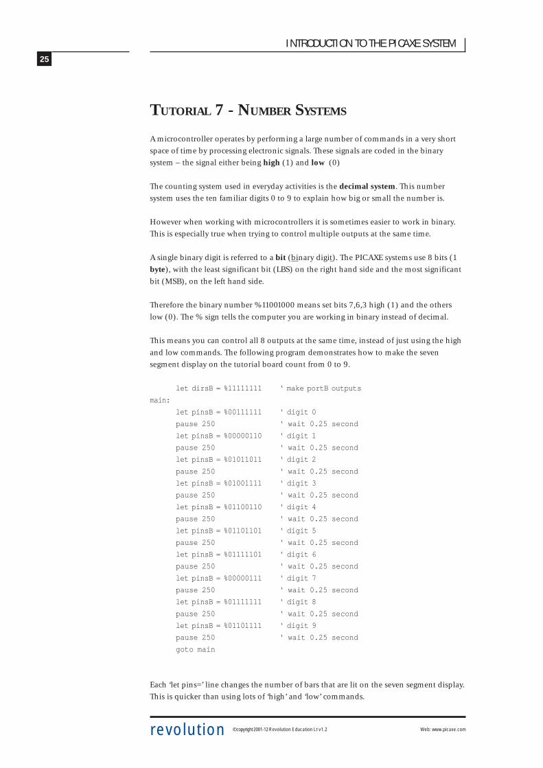
This means you can control all 8 outputs at the same time, instead of just using the high
and low commands. The following program demonstrates how to make the seven
segment display on the tutorial board count from 0 to 9.
let dirsB = %11111111 ‘ make portB outputs
main:
let pinsB = %00111111 ‘ digit 0
pause 250 ‘ wait 0.25 second
let pinsB = %00000110 ‘ digit 1
pause 250 ‘ wait 0.25 second
let pinsB = %01011011 ‘ digit 2
pause 250 ‘ wait 0.25 second
let pinsB = %01001111 ‘ digit 3
pause 250 ‘ wait 0.25 second
let pinsB = %01100110 ‘ digit 4
pause 250 ‘ wait 0.25 second
let pinsB = %01101101 ‘ digit 5
pause 250 ‘ wait 0.25 second
let pinsB = %01111101 ‘ digit 6
pause 250 ‘ wait 0.25 second
let pinsB = %00000111 ‘ digit 7
pause 250 ‘ wait 0.25 second
let pinsB = %01111111 ‘ digit 8
pause 250 ‘ wait 0.25 second
let pinsB = %01101111 ‘ digit 9
pause 250 ‘ wait 0.25 second
goto main
Each ‘let pins=’ line changes the number of bars that are lit on the seven segment display.
This is quicker than using lots of ‘high’ and ‘low’ commands.

26
INTRODUCTION TO THE PICAXE SYSTEM
revolution © copyright 2001-12 Revolution Education Lt v1.2 Web: www.picaxe.com
Displaying Analogue Values on the Seven Segment Display
This program reads the light value from the LDR sensor on input 2 and then displays a
value digit on the seven segment display.
let dirsB = %11111111 ‘ make portB outputs
main: readadc C.2,b1 ‘ read analogue pin 2 into variable b1
if b1 > 150 then show9 ‘ test variable b1 value and jump
if b1 > 130 then show8
if b1 > 110 then show7
if b1 > 90 then show6
if b1 > 70 then show5
if b1 > 50 then show4
if b1 > 30 then show3
if b1 > 20 then show2
if b1 > 10 then show1
show0:
let pinsB = %00111111 ‘ digit 0
goto main
show1:
let pinsB = %00000110 ‘ digit 1
goto main
show2:
let pinsB = %01011011 ‘ digit 2
goto main
show3:
let pinsB = %01001111 ‘ digit 3
goto main
show4:
let pinsB = %01100110 ‘ digit 4
goto main
show5:
let pinsB = %01101101 ‘ digit 5
goto main
show6:
let pinsB = %01111101 ‘ digit 6
goto main
show7:
let pinsB = %00000111 ‘ digit 7
goto main
show8:
let pinsB = %01111111 ‘ digit 8
goto main
show9:
let pinsB = %01101111 ‘ digit 9
goto main
27
INTRODUCTION TO THE PICAXE SYSTEM
revolution © copyright 2001-12 Revolution Education Lt v1.2 Web: www.picaxe.com
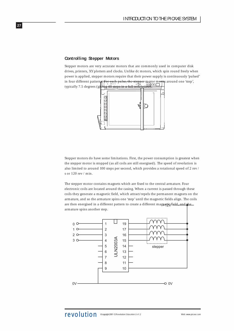
Controlling Stepper Motors
Stepper motors are very accurate motors that are commonly used in computer disk
drives, printers, XY plotters and clocks. Unlike dc motors, which spin round freely when
power is applied, stepper motors require that their power supply is continuously ‘pulsed’
in four different patterns. For each pulse, the stepper motor moves around one ‘step’,
typically 7.5 degrees (giving 48 steps in a full revolution).
Stepper motors do have some limitations. First, the power consumption is greatest when
the stepper motor is stopped (as all coils are still energised). The speed of revolution is
also limited to around 100 steps per second, which provides a rotational speed of 2 rev /
s or 120 rev / min.
The stepper motor contains magnets which are fixed to the central armature. Four
electronic coils are located around the casing. When a current is passed through these
coils they generate a magnetic field, which attract/repels the permanent magnets on the
armature, and so the armature spins one ‘step’ until the magnetic fields align. The coils
are then energised in a different pattern to create a different magnetic field, and the
armature spins another step.
���
����
�
�
�
�
#
$
�
�
/
0
�0
��
��
�$
�#
��
��
��
��
����
1,!55!
�
�
�
�
�� ��

28
INTRODUCTION TO THE PICAXE SYSTEM
revolution © copyright 2001-12 Revolution Education Lt v1.2 Web: www.picaxe.com
��������������� �
�
�
�
�
�
�
�
�
��
����
��
���
���
��
�� ���
��
�����
�
�
�
�
�
�
�
�
<!&&+:
!"
+ '49!
%&'()
% +:4
:;2,!
1,!55! *+,+
To make the armature rotate continuously the four coils inside the stepper motor must
be switched on and off in a certain step order. The ULN2003A driver chip on the tutorial
board provides the method of interfacing these four coils.
The stepper motor should be connected to the
holes on the tutorial board as follows:
Black Wire 2 +
White Wire 3 +
Yellow Wire 0 –
Red Wire 1 –
Orange Wire 2 –
Brown wire 3 –
The table below show the four different steps required to make the motor turn
Step Coil 4 Coil 3 Coil 2 Coil 1(Output 3) (Output 2) (Output 1) (Output 0)
1 1 0 1 0
2 1 0 0 1
3 0 1 0 1
4 0 1 1 0
1 1 0 1 0
To make the motor spin the other way the steps are reversed (i.e. 4-3-2-1-4 etc. rather
than 1-2-3-4-1 etc.).
Note:
The wiring configuration of stepper motors varies from different manufacturers.
Therefore, it may be necessary to rearrange the coil connections for the above sequence
to operate correctly. An incorrect coil arrangement will result in the stepper motor
vibrating back and forth rather than rotating. Most stepper motors are designed to
work at 12V, but will generally work (with reduced torque) at 6V.

29
INTRODUCTION TO THE PICAXE SYSTEM
revolution © copyright 2001-12 Revolution Education Lt v1.2 Web: www.picaxe.com
This program can also use a binary number that switches all of the output lines on and
off at the same time. The binary output number for each step is shown in the table
below:
Step Binary Output 1 %00001010
2 %00001001
3 %00000101
4 %00000110
1 %00001010
Try changing the speed by altering the value of delay in the following program.
symbol delay = b0 ‘ define the variable
let delay = 100 ‘ set delay to 0.1s
let dirsB = %11111111 ‘ make portB outputs
main: let pinsB = %00001010 ‘ first step
pause delay ‘ pause for delay
let pinsB = %00001001 ‘ next step
pause delay ‘ pause for delay
let pinsB = %00000101 ‘ next step
pause delay ‘ pause for delay
let pinsB = %00000110 ‘ next step
pause delay ‘ pause for delay
goto main ‘ loop forever

30
INTRODUCTION TO THE PICAXE SYSTEM
revolution © copyright 2001-12 Revolution Education Lt v1.2 Web: www.picaxe.com
TUTORIAL 8 - SUB-PROCEDURES
A sub-procedure is a separate ‘mini-program’ that can be called from the main program.
Once the sub-procedure has been carried out the main program continues.
Sub-procedures are often used to separate the program into small sections to make it
easier to understand. Sub-procedures that complete common tasks can also be copied
from program to program to save time.
The following program uses two sub-procedures to separate the two main sections of the
program( ‘flash’ and ‘noise’).
symbol dp = B.7 ‘ rename output7 ‘dp’
symbol buzzer = B.6 ‘ rename output6 ‘buzzer’
symbol counter = b0 ‘ define a counter using variable b0
main: ‘ make a label called ‘main’
gosub flash ‘ call the sub-procedure flash
gosub noise ‘ call the sub-procedure noise
goto main ‘ loop back
end ‘ end of the main program
flash: ‘ make a sub-procedure called flash
for counter = 1 to 25 ‘ start a for…next loop
high dp ‘ LED on
pause 50 ‘ wait 0.05 second
low dp ‘ LED off
pause 50 ‘ wait 0.05 second
next counter ‘ next loop
return ‘ return from the sub-procedure
noise:
high buzzer ‘ buzzer on
pause 2000 ‘ wait 2 seconds
low buzzer ‘ buzzer off
return ‘ return from the sub-procedure

31
INTRODUCTION TO THE PICAXE SYSTEM
revolution © copyright 2001-12 Revolution Education Lt v1.2 Web: www.picaxe.com
This second program shows how a variable can be used to transfer information into a
sub-procedure. In this case variable b2 is used to tell the microcontroller to flash 5, and
then 15, times.
symbol dp = B.7 ‘ rename output7 ‘dp’
symbol counter = b0 ‘ define a counter using variable b0
main: ‘ make a label called ‘main’
let b2 = 5 ‘ preload b2 with 5
gosub flash ‘ call the sub-procedure flash
pause 500 ‘ wait a while
let b2 = 15 ‘ preload b2 with 15
gosub flash ‘ call the sub-procedure flash
pause 500 ‘ wait a while
goto main ‘ loop back
end ‘ end of the main program
flash: ‘ make a sub-procedure called flash
for counter = 1 to b2 ‘ start a for…next loop
high dp ‘ LED on
pause 250 ‘ wait 0.25 second
low dp ‘ LED off
pause 250 ‘ wait 0.25 second
next counter ‘ next loop
return ‘ return from the sub-procedure

32
INTRODUCTION TO THE PICAXE SYSTEM
revolution © copyright 2001-12 Revolution Education Lt v1.2 Web: www.picaxe.com
Where next?
By completing these tutorials you have learnt all the basics about the PICAXE system –
how to setup the system, how to develop programs, how to draw flowcharts and how to
connect input and output devices. On the CDROM there are also some other very useful
reference guides which will provide you with further information.
Further informatuion is available in the full PICAXE manual.
Exemplar ProjectsThe next reference point should be the exemplar projects, which give real life examples
of how the PICAXE system can be used in the real world. Each project provides a sample
circuit diagram and program listing, which may be copied or altered to meet your project
requirements.
PICAXE Manual - Part 2 - BASIC Command GuideThe BASIC language used by the PICAXE has over 30 commands, of which we have only
used a few in this tutorial. Have a look through the other commands available, each
command has a small program to demonstrate how it can be used within a project.
PICAXE Manual - Part 1 - Interfacing Electronics GuideThis guide explains how to ‘interface’ a large number of input and output devices to the
PICAXE microcontroller. If you want to know how to connect a buzzer, motor, solenoid
or LDR to the PICAXE, the answer is here!
Finally all the latest information, and a technical support forum, are available on the
internet at www.picaxe.com
GOOD LUCK WITH YOUR PICAXE PROJECT!

33
INTRODUCTION TO THE PICAXE SYSTEM
revolution © copyright 2001-12 Revolution Education Lt v1.2 Web: www.picaxe.com
APPENDIX 1: EQUIPMENT REQUIRED
All equipment can be purchased from the online store at
www.techsupplies.co.uk
See the PICAXE section for details on the PICAXE parts.
Equipment Required for tutorials within this booklet:
PICAXE18M2 Tutorial Board Pack (AXE050U)
3 x AA batteries (BAT002)
Optional Connectors:
3 x 4pole screw terminal block (CON005)
Optional Output Devices:
SPE002 Piezo Sounder
GBX007 Solar DC Motor
GBX008 Unipolar Stepper Motor
34
INTRODUCTION TO THE PICAXE SYSTEM
revolution © copyright 2001-12 Revolution Education Lt v1.2 Web: www.picaxe.com
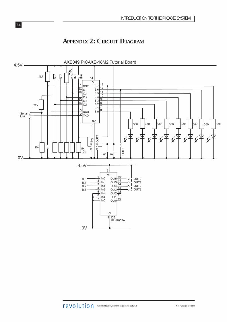
APPENDIX 2: CIRCUIT DIAGRAM
#�
�/
��
��������0/��
����#0-�������/��-�3,+ 2'&-.+' "#�$�
�������������
����
��
�! 2'&�24)
��.��.��.�$.�#.��.��.��.��
��
$
�#
��� ������ ��� ������ ��� ���
�
��) $=��)
��)
#)�
�
#���/�
�$��
��
���
�
��
�
��
���
���
���$�#��������
�4��4$�4#�4��4��4��4�
��
�� 3,� 3,$ 3,# 3,� 3,� 3,� 3,�
0
���#$��
��� ��� ��� ���
/ ����������
��
#�$�
.��
.��
.��
.��