
Contents · Contents 1. Introduction ... It describes the device and the operation of the GSM modem...
25
Transcript of Contents · Contents 1. Introduction ... It describes the device and the operation of the GSM modem...


2
Contents
1. Introduction ............................................................................................................................. 4
1.1. Document description..................................................................................................................... 4
1.2. Service data ................................................................................................................................... 4
1.3. Safety rules .................................................................................................................................... 4
2. General Information ................................................................................................................ 5
2.1. Purpose.......................................................................................................................................... 5
2.2. Set ................................................................................................................................................. 5
2.3. Features......................................................................................................................................... 5
2.4. Appearance.................................................................................................................................... 7
2.5. Interfaces ....................................................................................................................................... 8
2.5.1. Plug-in terminal connector....................................................................................................... 8
2.6. Power connector............................................................................................................................. 9
2.6.1. Digital connector ................................................................................................................... 10
2.7. Modem status display ................................................................................................................... 11
3. Functional diagram and operation description................................................................... 12
3.1. Functional diagram ....................................................................................................................... 12
3.2. Operation description.................................................................................................................... 12
3.3. Watchdog timer types................................................................................................................... 13
4. Connecting and configuring................................................................................................. 14
4.1. Connecting ................................................................................................................................... 14
4.2. Control, rebooting and connecting................................................................................................. 14
4.3. Menu mode .................................................................................................................................. 15
4.4. Programming mode ...................................................................................................................... 18
5. Creating, installing and deleting of Java-applications ....................................................... 21
6. Emergencies.......................................................................................................................... 24
6.1. Emergency 1 (incorrect input power supply).................................................................................. 24
6.2. Emergency 2 (incorrect module power supply).............................................................................. 24
6.3. Emergency 3 (GSM module failed to start).................................................................................... 24
7. Support .................................................................................................................................. 25
3
Tables
Table 2.5.1: Using terminal connector pins ........................................................................................ 8
Table 2.5.2: Using connector power pins........................................................................................... 9
Table 2.5.3: Using digital connector pins ......................................................................................... 10
Table 2.6.1: Connection status diplay (green LED).......................................................................... 11
Table 2.6.2: Emergency display (red LED) ...................................................................................... 11
Figures
Fig. 2.4.1. Front view ......................................................................................................................... 7
Fig. 2.4.2. Back view.......................................................................................................................... 7
Fig. 2.5.1. Plug-in terminal connector................................................................................................. 8
Fig. 2.5.2. Power connector ............................................................................................................... 9
Fig. 2.5.3. Digital connector ............................................................................................................. 10
Fig. 3.1.1. Functional diagram of the modem................................................................................... 12
Fig. 4.4.1. «My Computer» window of Windows XP......................................................................... 21
Fig. 4.4.2. COM-port selecting ......................................................................................................... 21
Fig. 4.4.3. Working with «Module» Disk ........................................................................................... 22
Fig. 4.4.4. General view of «AutoExec» ........................................................................................... 23

4
1. Introduction
1.1. Document description
This manual is intended for experienced PC users. It describes the device and the operation of the GSM
modem iRZ TC65i-485GI.
1.2. Service data
Document version Issue date 2.11 09.20.2013
Prepared by V.N. Golovin Approved by P.A. Kosolapov
1.3. Safety rules
Restrictions on the use of the device near other electronic devices:
Turn the modem off in hospitals or when located near medical equipment such as pacemakers, hearing
aids and so on. Interference for medical equipment may occur
Turn the terminal off when on an airplane. Take measures to avoid accidental turning on
Turn the modem off in the vicinity of gas stations, chemical plants, and places where demolition work is
conducted. Interference for technical devices may occur
At a close range, the modem may produce interference for television sets and radio transmitters
Maintenance requirements:
Protect the modem against external hazards (high temperatures, caustic chemicals, dust, water and so
on)
Keep the modem safe from blows, falls, and strong vibrations
Do not attempt to take apart or modify the modem on your own. Such actions will void your warranty
Note: Make sure you follow the operation manual for this device. Improper use of the device will disqualify your warranty.
5
2. General Information
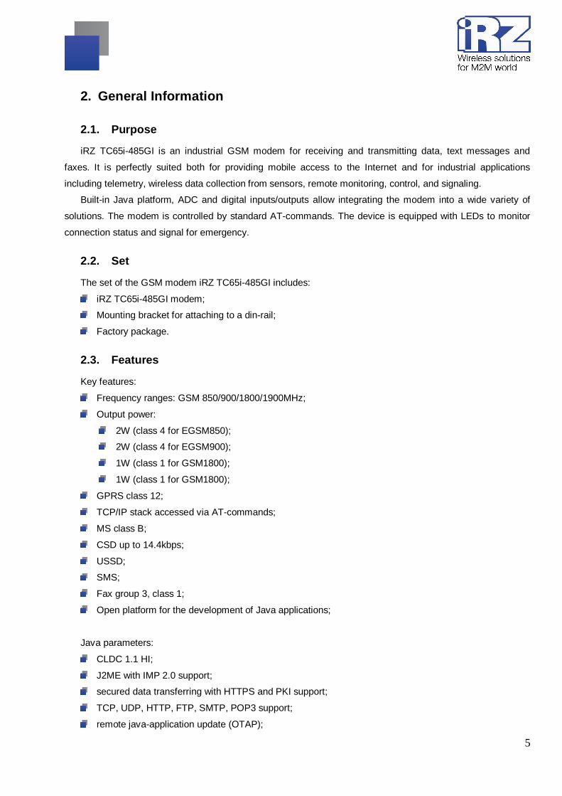
2.1. Purpose
iRZ TC65i-485GI is an industrial GSM modem for receiving and transmitting data, text messages and
faxes. It is perfectly suited both for providing mobile access to the Internet and for industrial applications
including telemetry, wireless data collection from sensors, remote monitoring, control, and signaling.
Built-in Java platform, ADC and digital inputs/outputs allow integrating the modem into a wide variety of
solutions. The modem is controlled by standard AT-commands. The device is equipped with LEDs to monitor
connection status and signal for emergency.
2.2. Set
The set of the GSM modem iRZ TC65i-485GI includes:
iRZ TC65i-485GI modem;
Mounting bracket for attaching to a din-rail;
Factory package.
2.3. Features
Key features:
Frequency ranges: GSM 850/900/1800/1900MHz ;
Output power:
2W (class 4 for EGSM850);
2W (class 4 for EGSM900);
1W (class 1 for GSM1800);
1W (class 1 for GSM1800);
GPRS class 12;
TCP/IP stack accessed via AT-commands;
MS class B;
CSD up to 14.4kbps;
USSD;
SMS;
Fax group 3, class 1;
Open platform for the development of Java applications;
Java parameters:
CLDC 1.1 HI;
J2ME with IMP 2.0 support;
secured data transferring with HTTPS and PKI support;
TCP, UDP, HTTP, FTP, SMTP, POP3 support;
remote java-application update (OTAP);
6
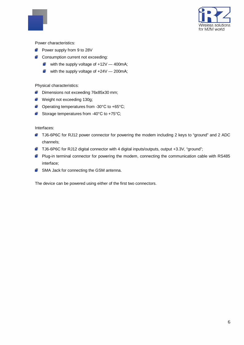
Power characteristics:
Power supply from 9 to 28V
Consumption current not exceeding:
with the supply voltage of +12V — 400mА;
with the supply voltage of +24V — 200mА;
Physical characteristics:
Dimensions not exceeding 76х85х30 mm;
Weight not exceeding 130g;
Operating temperatures from -30°С to +65°С;
Storage temperatures from -40°С to +75°С;
Interfaces:
TJ6-6P6C for RJ12 power connector for powering the modem including 2 keys to “ground” and 2 ADC
channels;
TJ6-6P6C for RJ12 digital connector with 4 digital inputs/outputs, output +3.3V, “ground”;
Plug-in terminal connector for powering the modem, connecting the communication cable with RS485
interface;
SMA Jack for connecting the GSM antenna.
The device can be powered using either of the first two connectors.
7
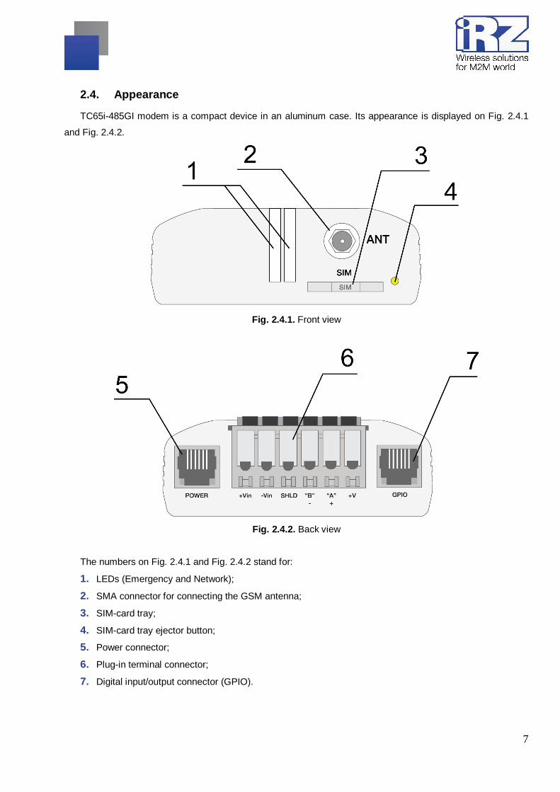
2.4. Appearance
TC65i-485GI modem is a compact device in an aluminum case. Its appearance is displayed on Fig. 2.4.1
and Fig. 2.4.2.
Fig. 2.4.1. Front view
Fig. 2.4.2. Back view
The numbers on Fig. 2.4.1 and Fig. 2.4.2 stand for:
1. LEDs (Emergency and Network);
2. SMA connector for connecting the GSM antenna;
3. SIM-card tray;
4. SIM-card tray ejector button;
5. Power connector;
6. Plug-in terminal connector;
7. Digital input/output connector (GPIO).

8
2.5. Interfaces
2.5.1. Plug-in terminal connector
This connector is used for communication with a controlling device, interface RS485. The AT-commands
are used to control the modem operation (see the module description).
Factory settings: Speed: 115200 bps, Data Bit: 8, Parity: None, Stop Bit: 1.
Fig. 2.5.1. Plug-in terminal connector
Table 2.5.1: Using terminal connector pins
Pins Signal Purpose 1 +Vin “+” modem power supply 2 -Vin “-” modem power supply 3 SHLD “Shield” of RS485 interface 4 “B” “d-“ of RS485 interface;
inverse differential I/O 5 “A” “d+“ of RS485 interface;
direct differential I/O
Interface lines are protected by self-healing fuses and a circuit of impulse noise suppression, as well as overvoltage protection
6 +5V Output ”+5V” (RS485), 100mA (to power external devices)*
*For instance, it might be used to power RS485 interface of heat and electricity counters, etc.
Notes: RS485 interface is half duplex. It needs to be considered in case of data transfer. When echo is enabled, data is sent to the modem will return. This can lead to collision. In this case we recommend to disable echo (AT-command ate0).

9
2.6. Power connector
TJ6-6P6C for RJ12 power connector is used to power the device. Also displayed on Fig. 2.5.2 are two keys
to the “ground” and two ADC channels.
Fig. 2.6.1. Power connector
Table 2.6.1: Using connector power pins
Contact Signal Purpose 1 + 12V The positive pole of DC supply voltage. Fused circuit and overvoltage
protection (when input voltage of over 30V is applied) and reverse polarity 2 Output of the “dry
contact” type to the ground
Controlled by GPIO4 module output. When “logical 1” exits from the module output, the “dry contact” output shortens to the “ground”
3 ADC2 Analog to digital converter. Parameters of the input circuit include input resistance of 180kOhms and input voltage divider by 10. Connected to the ADC2 pin of the GSM module
4 ADC1 Analog to digital converter. Parameters of the input circuit include input resistance of 180kOhms and input voltage divider by 10. Connected to the ADC1 pin of the GSM module
5 Output of the “dry contact” type to the ground
Controlled by GPIO5 module pin. When “logical 1” exits from the module output, the “dry contact” output shortens to the “ground”
6 GND Ground
Output of the “dry contact” type goes through a 10 Ohm resistor to the collector of the BC817 transistor.
The output of the GSM module goes to the transistor base. The emitter of the transistor is connected to the
“ground”. The maximum current of the “dry contact” output is 80mA.

10
2.6.1. Digital connector
The connector has 4 digital pins. Both inputs and outputs can be used, which is specified in the GSM
module settings.
Fig. 2.6.2. Digital connector
Table 2.6.2: Using digital connector pins
Contact Signal Purpose 1 GND Body of the system or “ground” 2 GPIO2 Digital output controlling pin of GPIO2 module 3 GPIO1 Digital output controlling pin of GPIO1 module 4 GPIO10 Digital output controlling pin of GPIO10 module 5 GPIO3 Digital output controlling pin of GPIO3 module 6 +V +3.3V voltage of the modem
Parameters:
VOLmax=0.2V, I=2mA;
VOHmin=2.5V, I=-0.5mA;
VOHmax=3.0V;
VILmax=0.8V;
VIHmin=2.2V;
VIHmax=3.0V.
The input/output resistance of digital pins is 1kOhm. In order to send the controlling signals to the digital
pins it is recommended to use the first and the sixth pins of the connector.

11
2.7. Modem status display
Two LEDs indicate current working mode (connection status) or signal for an emergency. This function can
be controlling by a corresponding AT-command (AT^SSYNC=1 — LED mode on; AT^SSYNC=0 — LED mode
off). By default, AT^SSYNC=1.
Table 2.7.1: Connection status diplay (green LED)
Display mode Conventional indication display
Operation mode
Turned off ○ Modem is turned off or is in the emergency status
600ms on / 600ms off ●●●●●●○○○○○○ Modem has not been registered online
75ms on / 3s off ●○○○○○○○○○...○ Modem has been registered online
75ms on / 75ms off / 75ms on / 3s off
●○●○○○○○○○...○ GPRS connection has been established
500ms on / 50ms off ●●●●●○ Data transmission is under way
250ms on / 10s off ●●●○○○○○○○...○ Modem is in the sleep mode, alarm clock mode
250ms on / 250ms off ●●●○○○ Programming mode, menu mode
Permanently turned on ● Voice call, CSD
Configurations of display mode with "AT^SSYNC=2" and "AT^SSYNC=1" is differ only by power saving
mode. For more information, see GSM module documentation.
Table 2.7.2: Emergency display (red LED)
Display mode Conventional indication display
Emergency description
Permanently turned on ● Invalid input voltage
0.5s on / 0.5s off ●●○○ Invalid module power supply
0.25s on / 0.25s off / 0.25s on / 1s off
●○●○○○○ GSM module has not launched

12
3. Functional diagram and operation description
3.1. Functional diagram
The functional diagram of the modem is displayed on Fig. 3.1.1.
Fig. 3.1.1. Functional diagram of the modem
3.2. Operation description
The operation mode of the modem changes depending on the presence of the SIM-tray. When the SIM-tray
is installed, the modem is in the operation mode meaning that the pins of the RS485 interface of the umbilical
connector are wired to the UART0 of the GSM module, UART of the managing microcontroller is connected to
the UART1 of the GSM module, and the GSM module is tuned on.
In case the SIM-tray is missing the modem is either in the programming mode (the SIM-tray was removed
before powering the modem) or the menu mode (the SIM-tray was removed after powering the modem). In both
cases the GSM modem is turned off (the modem’s power is shut down), and the RS485 interface pins of the
umbilical connector are wired to the UART of the managing microcontroller.
The programming mode allows updating the software of the managing microcontroller. The menu mode
allows changing the modem’s parameters and access the statistics.

13
The modem can be powered using either of the two connectors: the power connector or the umbilical
connector.
3.3. Watchdog timer types
Several types of watchdog timers are provided in the GSM modem:
Built-in watchdog timer in the managing microcontroller. The microcontroller itself is monitored for a
possibility of software crash (It is permanently on and cannot be turned off);
A regular check by the managing microcontroller for a possibility of the GSM module deadlock of the
Java-application. The interval can be set by the user in the range from 1 to 255 minutes in 1 minute
increments. The principle of its operation implies that the managing microcontroller periodically sends
the “at” command (speed 115200b/s, 8-N-1) to the second COM-port of the module and waits for a
response “at”, then “OK”. Also, after each command, there should be “\r=CR \n=LF”. The response
should be analogous to the response of the module without the Java-application with enabled echo. If
no response is received the GSM module reboots. The module’s power in the meantime is shut down.
This function can be activated or deactivated in the menu mode. This function is switched off by default;
Note: Java-application can occupy this COM-port, which will result in constant reloading of the module (where the function is activated).
An unconditional reboot of the modem after a period of time set by user. This function is switched off by
default. The period of time can be set between 1 and 255 hours in 1 hour increments. The principle of
its operation implies that the managing microcontroller after a set period of time reboots the GSM
module and the module’s power is shut down. The control of this function is done in the menu mode
(see Part 4.3).

14
4. Connecting and configuring
4.1. Connecting
Only individuals with specialized technical training and who have studied the product specifications are
permitted to assemble (install) the modem.
Before connecting the device, install the SIM-card (mini SIM, 15x25mm) into the modem. In order to do
that:
Eject the SIM-tray by pressing the SIM-card tray ejector button (Fig.2.4.1);
Place the SIM-card into the SIM-card tray;
Insert the SIM-card tray into the modem.
Be careful when installing the SIM-card.
Connect the GSM antenna and the commuting USB or RS232 cable. The modem can be powered using
the USB cable. If needed the modem can be powered using the TJ6-6P6C power connector (see Fig. 2.5.2).
Note: GSM antenna, the commuting cables and the power supply are not included in the set.
4.2. Control, rebooting and connecting
The modem is controlled using standard AT-commands. You can find additional information and support at
www.irz.net.
The modem can be rebooted using one of the following ways:
Rebooting after a given period of time (WD interval, turned off by default), setting is done in the menu
mode;
By AT-command “AT+CFUN=1,1”;
Temporary power shutdown.
The modem can be shut down using one of the following ways:
Program method using AT-commands only in case transition to sleep mode is allowed;
Power shutdown.
When modem is disabled by using AT-commands, you can use the alarm function (ALARM mode) to run
modem.
Switch-over of modem into power saving mode by using AT-command "AT+CFUN". Controlling the alarm
mode by using AT-command “AT+CALA”. For more detail see AT-commands description for the GSM module.

15
4.3. Menu mode
The menu mode’s function is to change the modem’s parameters and access the statistics. In this mode,
the power of the GSM module is switched off. After leaving the menu mode automatic rebooting takes place. To
access the menu mode from the operation mode remove the SIM-tray. Before accessing the menu mode
connect the modem to the computer through the DB9 connector. Run Hyper Terminal or a similar program.
Remove the SIM-tray (by pressing the SIM-tray ejector button). The modem will go into the menu mode:
Menu mode:
Variant XX
<P1> View statistics
<P2> WD interval=OFF
<P3> 'AT' control=OFF
<PC> Power control
<PR> Clear statistic
<PS> Change speed: auto
Variant XX is the software version
Symbols <P…> stand for control commands. A command is sent after pressing “Enter”. If an incorrect
command has been sent, the “ERROR” message appears. Entering commands is case-insensitive.
After entering the <P1> command a transition into the submenu of statistics occurs:
Statistics:
Power_Modem = XX…X
Bad_Power_Modem = XX…X
Power_Module = XX…X
Bad_Power_Module = XX…X
Start_Module = XX…X
Bad_Start_Module = XX…X
Deadlock_of_Module = XX…X
Reset = XX…X
The modem automatically stores the number of the following situations:
Power_Modem – the number of times the modem has been turned on;
Bad_Power_Modem – the number of times the modem power has deviated from the allowed; Power_Module – the number of times the power of the GSM module has been turned on;
Bad_Power_Module – the number of times the GSM module power has deviated from the allowed;
Start_Module – the number of the successful launches of the GSM module;
Bad_Start_Module – the number of situations when the GSM module failed to launch;
ComPort_is_not_Running – the number of situations when the COM-port of the module is not ready (the
CTS signal is being analyzed);

16
Deadlock_of_Module – the number of GSM module deadlocks;
Reset – the number of resets.
After the statistics appears the transition to the main menu occurs.
Use <P2> command to proceed to the WD submenu:
WD interval, hour (0 - WD off, max - 255)
<Q> Quit
WD interval=
The interval of the unconditional reboot of the module is set. To change the reboot interval, enter a number
from 0 to 255 (by pressing “Enter”). The reboot interval is set in hours. If you need to switch off this function
enter 0. Keep in mind that after the set interval expires, the unconditional reboot of the modem will occur. In
case incorrect information is entered the modem displays “ERROR” and offers the WD submenu once again. In
case correct information is entered or <Q> command is sent a transition into the main menu takes place.
Use <P3> command to proceed to the AT submenu:
'AT' control, minutes (0 - off, max - 255)
<Q> Quit
control=
In this submenu the interval of the periodical check by the managing microcontroller of the GSM module
deadlock is set. To change the interval of the check enter a number from 0 to 255 by pressing “Enter”. The
reboot interval is set in minutes. If you need to switch off this function enter 0. In case incorrect information is
entered the modem will show “ERROR” and will offer the AT submenu once again. In case correct information
is entered or <Q> command is sent a transition into the main menu will take place.
Note: If you using remote Java-application’s update (OTAP), the interval of periodic inspection must be less than the time of Java-application’s loading. Usually is a 10 minutes max.
After entering <PC> command review the input voltage and the voltage of the module (measurement
precision 5%):
P0WER Uin=12.0 Umd=3.9
After the output a transition into the main menu occurs.

17
After entering the <PR> command a transition into the submenu of clearing the statistics occurs:
Clear statistics?
<YES> YES
<Q> Quit
The accumulated statistics is cleared by the <YES> command. In case incorrect information is entered the
modem displays “ERROR” and offers the submenu of clearing the statistics once again. In case correct
information is entered or <Q> command is sent a transition into the main menu takes place.
After entering the command <PS> a transition into the menu of determining data transmission speed in the
operation mode occurs. Modem is always set to receive data. A switch to transition occurs when data to be
transmitted appears. Setting a fixed speed of data transmission eliminates errors in calculating the interval of
transmission switch. This allows minimizing pauses between transmission and reception of data and to
eliminate the disappearance of data transmission start. By default, the modem is set to determine the data
transmission speed automatically.
<0> auto
<1> 115200
<2> 57600
<3> 38400
<4> 28800
<5> 19200
<6> 14400
<7> 9600
<8> 4800
<9> 2400
<10> 1200
<11> 600
<12> 300
<Q> Quit
To choose the data transmission speed enter a number between 1 and 12 (by pressing “Enter”). If you
need to switch off this function enter “0”. In case incorrect information is entered, the modem will display
“ERROR” and will offer the menu of determining data transmission speed once again. In case correct rebooting
interval is entered or <Q> command is sent, a transition into the main menu will take place.
After entering the <M> command the main menu appears.
The exit from the menu mode occurs after the SIM-tray is installed back again.

18
4.4. Programming mode
Program “mprog” is used to change or update software of the managing microcontroller of the modem.
Figure 3.1 shows an external view and main features:
1 – language, 2 – working with ports, 3 – working with Flash, 4 – working with EEPROM, 5 – start button,
6 – view window.
Fig. 4.1. Main view
If within 10 seconds after powering the device an update has not started, the modem will leave the
programming mode and enter the menu mode.
To change the software do the following:
1. Start the program
Close all programs, which can use the port you will connect to the modem.
2. Click the button in “Port” frame;
3. Choose the number of the COM port where the modem will be connected
4. Connect the modem (without the SIM holder) to the computer and turn on the modem;
Turn on the modem. The modem will go into the programming mode. The green LED will blink: 250ms on /
250ms off. “Open” button (not later than 10 sec once the modem was powered).

19
5. Click the button (not later than 10 sec once the modem was powered) in “Port’
frame;
The device model should appear. For example see figure 3.2 – “MC52i-485” (or “BGS2-485”).
Fig. 4.2. Port opening
Then select the new firmware file to be downloaded.
6. Click the button in “Flash” frame and choose firmware file (file in “hex”-format) in
«Open file» dialog
For example see figure 3.3 – “rs485_bgs2_v4.0.hex”.
Fig. 4.3. File uploading
If the file has uploaded successfully, the program window will show message “Uploaded file:”.
Fig. 4.4. File is uploaded
7. Click the button in “Flash” frame
After this, data will be written in Flash-memory and you see such text:

20
Fig. 4.5. Flash-memory writing
8. Next click the button in bottom part of program window;
This will make the modem exit from programming mode and the port will be closed.
Fig. 4.6. Exiting program mode
9. Close the program
10. Place the SIM holder into the modem
The software update is completed. The modem goes into the work mode.

21
5. Creating, installing and deleting of Java-applications This modem based on module Cinterion TC65i with built-in Java platform, which allows for many tasks. You
can create, install and delete Java-applications with special tools from Cinterion company, “Module Exchange
Suite” (MES) application. The software is available at www.irz.net, or from delivering on CD/DVD from our
managers.
After «Module Exchange Suite» is installed, in the root directory shall be added the drive “Module”:
Fig. 4.4.1. My Computer window of Windows XP
In disk properties (Port tab) select COM-port, which connected with the modem:
Fig. 4.4.2. Select COM-port

22
Fig. 4.4.3. Working with “Module” Disk
Working with “Module Exchange Suite” is to copy and delete needed files to disk “Module”. For example, to
install the Java-based applications simply copy the files to disk “Module”.
Autostart of Java-based applications is given by the following AT-commands:
AT^SCFG="userware/autostart/appname","","a:/ХХХ.jar" (where ХХХ is file name);
AT^SCFG="userware/autostart/delay","","100" (autostart after 10 seconds after module is turned on);
AT^SCFG="userware/autostart","","1" (autostart is enable).
For startup is recommended to set the interval of about 10 seconds. This is especially important when you
testing the new Java-based applications. This further simplifies the process of abolishing the autostart. After the
startup of Java-based application, port may not respond to AT-commands.
To remove Java-based applications, you need to cancel autostart. This can be done by AT-command
AT^SCFG="userware/autostart","","0" if it was set in advance sufficient interval of autostart. You must sent
this AT-command should be after 2-5 seconds after the power to the modem. After a successful attempt to sent
AT-command, the modem must answer “OK”.

23
Fig. 4.4.4. General view of «AutoExec» application
If the specified autostart interval does not allow send AT-command to cancel autostart, in this case use the
program “autoexec_off.exe” (attached to the development software). Sequence of actions shall be as follows:
connect the modem to the computer,
run «autoexec_off.exe», and at the program window, enter the number of COM-port,
power on the modem and after 1-3 seconds click on «AutoExec Off» button (need to get in the time
interval between the start of the module and the launch of Java-based application).
If autorun is turned off, then message should appear: “AutoExec successfully switched off”.
To delete Java-based applications is to remove the files on the disk Module». Provides the ability to
remotely update Java-based applications - «Over The Air Provisioning» (OTAP). More information can be
found in the documentation, which is part of the disk with the software for developing.

24
6. Emergencies To facilitate the use of the modem, tracking and display of emergencies are provided.
6.1. Emergency 1 (incorrect input power supply)
Emergency 1 occurs when the input power supply deviates from the permissible value. The modem stops
working and it shuts down the GSM module power. A permanent red LED signals that the emergency has
occurred. The recovery is possible only when the input power supply is re-established.
6.2. Emergency 2 (incorrect module power supply)
Emergency 2 occurs when the GSM module power supply deviates from the permissible value. The modem
stops working and it shuts off the GSM module power. A red LED signals that the emergency has occurred
(0.5s on / 0.5s off). The recovery is possible only if the module power supply is re-established within 10
seconds after the emergency occurred. If within 10 seconds the module power supply remains incorrect (with a
correct input power supply), the modem goes into the waiting mode meaning that the modem’s power supply is
turned off, the emergency indication is preserved. The waiting mode can be terminated only after the power is
completely disconnected.
In case of repeated emergency, the modem should be serviced.
6.3. Emergency 3 (GSM module failed to start)
Emergency 3 occurs if the GSM module does not turn on or is absent. A red LED signal (0.25s on / 0.25s
off / 0.25s on / 1s off) turns on after a precise determination by the modem of the emergency situation (~15
sec). The recovery is possible only after a successful launch of the GSM module. After 10 unsuccessful
attempts to launch the module, the modem goes into the waiting mode meaning that the modem’s power
supply is turned off, the emergency indication is preserved. The waiting mode can be terminated only after the
power is completely disconnected.
In case of repeated emergency after the modem is turned back on, the modem should be serviced.

25
7. Support New document versions and software are available using:
St. Petersburg
The company’s website: www.radiofid.ru
Phone number in St. Petersburg: +7 (812) 318 18 19
E-mail: [email protected]
Moscow
The company’s website: www.digitalangel.ru
Phone number in Moscow: +7 (495) 974 74 22
E-mail: [email protected]
Our support team is ready to assist you with any questions you might have when installing, configuring or
solving issues with our equipment.


![IRZ artificial lift solutions [version 1.4 july 2016]](https://static.fdocuments.in/doc/165x107/5878547d1a28ab68198b6f2b/irz-artificial-lift-solutions-version-14-july-2016.jpg)