1 GAS LIFT EQUIPMENT - Botil Oil Tools India Pvt Ltdbotilindia.com/Gas Lift Equipment.pdf · Test...
30
GAS LIFT EQUIPMENT 1 SIDE POCKET MANDREL (WRVM) Product No. BI 820-02 BOTIL Side Pocket Mandrels allow use of standard Wireline tools for installation and retrieval of different types of flow control devices. MATERIALS: Generally Low Alloy Steel AISI 4130 is used. For corrosive application, AISI 410 is used. Other materials may be used as per customer’s requirement. FORGINGS: Pockets & tool discriminators are closed die forged and are integral part of the pocket. Swages are forged from seamless mechanical tubing or it can be machined from solid bar stock. Forgings are made by using a precision closed die process. All forged parts are visually and dimensionally inspected by Quality Control before machining. After Heat Treatment, additional testing i.e. Grain Flow, Micro Examination, Hardness Testing, Dye Penetrant Testing Magnetic Particle Testing & Ultra Sonic Testing are also carried out. MACHINING: Pockets are machined using Deep Hole Drilling & boring process that provides accurate polished bore diameters, alignment and better surface finish for packing seals. The swages are machined with precision accuracy. Threads are machined as per design specification. All components are dimensionally inspected. WELDING HEAT TREATMENT: Welding is done as per ASME Section VIII & IX with the use of proper welding electrodes. Full penetration welds take place when joining the swages and forged pocket are welded to the oval pipe. After welding, all external weld deposits are evenly grounded down to match the outside profile. All mandrels are heat treated, Quenched & Tempered to 18-22 HRC, for corrosive service and 24-33 HRC for standard service application. ASSEMBLED MANDREL: After heat treatment and threading each mandrel is tested for hardness, internal and external drift and pressure test. Additional testing i.e. dye penetrant, ultrasonic, magnetic particle and radiography can also be provided as per customer requirement . 107
Transcript of 1 GAS LIFT EQUIPMENT - Botil Oil Tools India Pvt Ltdbotilindia.com/Gas Lift Equipment.pdf · Test...

GAS LIFT EQUIPMENT1
SIDE POCKET MANDREL (WRVM)Product No. BI 820-02
BOTIL Side Pocket Mandrels allow use of standardWireline tools for installation and retrieval ofdifferent types of flow control devices.
MATERIALS:Generally Low Alloy Steel AISI 4130 is used.For corrosive application, AISI 410 is used.Other materials may be used as percustomer’s requirement.
FORGINGS:Pockets & tool discriminators are closed die forgedand are integral part of the pocket. Swagesare forged from seamless mechanical tubing or itcan be machined from solid bar stock. Forgingsare made by using a precision closed dieprocess. All forged parts are visually anddimensionally inspected by Quality Controlbefore machining. After Heat Treatment,additional testing i.e. Grain Flow, MicroExamination, Hardness Testing, Dye PenetrantTesting Magnetic Particle Testing & UltraSonic Testing are also carried out.
MACHINING:Pockets are machined using Deep Hole Drilling &boring process that provides accurate polishedbore diameters, alignment and better surface finishfor packing seals. The swages are machined withprecision accuracy. Threads are machined as perdesign specification. All components aredimensionally inspected.
WELDING HEAT TREATMENT:Welding is done as per ASME Section VIII &IX with the use of proper welding electrodes.Full penetration welds take place when joiningthe swages and forged pocket are welded to theoval pipe. After welding, all external welddeposits are evenly grounded down to match theoutside profile. All mandrels are heat treated,Quenched & Tempered to 18-22 HRC, forcorrosive service and24-33 HRC for standard service application.
ASSEMBLED MANDREL:After heat treatment and threading each mandrel istested for hardness, internal and external drift andpressure test. Additional testing i.e. dye penetrant,ultrasonic, magnetic particle and radiography canalso be provided as per customer requirement.
107
Other Drift sizes can also be provided upon* request.
ENGINEERING DATA FOR SIDE POCKET MANDREL (WRVM)
TubingSize
(Inch)
Valve OD(Inch)
Mandrel Dimensions (Inch)
Type Shape LengthA
MajorODB
MinorODC
I.D.ØD
*DriftDia.
ØEE
ØFF
2 3/8 1.0 B1M OVAL 83 4.25 2.92 2.000 1.901 1.027 1.0272 3/8 1.5 B2M OVAL 102 4.75 4.00 2.000 1.901 1.600 1.5002 7/8 1.0 B1M OVAL 85 4.75 4.00 2.441 2.347 1.027 1.0272 7/8 1.5 B2M OVAL 103 5.50 4.59 2.441 2.347 1.600 1.5003 1/2 1.0 B1M OVAL 85 5.31 4.12 2.992 2.867 1.027 1.0273 1/2 1.5 B2M OVAL 104 6.06 5.00 2.992 2.867 1.600 1.5004.0 1.0 B1M OVAL 86 5.85 5.00 3.476 3.351 1.027 1.0274.0 1.5 B2M OVAL 107 6.63 5.55 3.476 3.351 1.600 1.500
4 1/2 1.0 B1M OVAL 90 5.86 5.00 3.897 3.790 1.027 1.0274 1/2 1.0 B1M OVAL 86 6.45 5.50 3.958 3.833 1.027 1.0274 1/2 1.5 B2M OVAL 107 7.03 5.625 3.958 3.833 1.600 1.5005.0 1.5 B2M OVAL 116 7.94 6.80 4.408 4.283 1.600 1.500
5 1/2 1.0 B1M OVAL 87 7.94 6.80 4.778 4.653 1.600 1.5005 1/2 1.5 B2M OVAL 115 7.44 6.05 4.000 3.833 1.600 1.5005 1/2 1.5 B2M OVAL 115 7.94 6.80 4.778 4.653 1.600 1.500
GAS LIFT EQUIPMENT
108

Test Pressure given are for mandrels made of AISI-4130 (9Cr 1Mo, 13Cr)* materials
heat treated for Standard or Corrosive environments. Test Pressure may bereduced due to end connection limitations.
Weight & Length may vary depending upon end** connection
PRESSURE RATING FOR SIDE POCKET MANDRELS (WRVM)
TubingSize
(Inch)
ValveO.D.
(Inch)
MandrelType
WeightLbs - F*(Kg - F)
Volume(Cubic
Ft.)
Test Pressure (PSI) *StandardServices
CorrosiveServices
Internal External Internal External2 3/8 1.0 B1M 73 (33) 0.47 8000 7000 6000 55002 3/8 1.5 B2M 128 (58) 0.88 7500 6500 6000 50002 7/8 1.0 B1M 119 (54) 0.73 8000 7000 6000 55002 7/8 1.5 B2M 179 (81) 1.18 7500 6500 6000 50003 1/2 1.0 B1M 148 (67) 0.84 8000 6500 6000 50003 1/2 1.5 B2M 207 (94) 1.43 8000 6500 7000 55004.0 1.0 B1M 203 (92) 1.14 8000 6500 7000 55004.0 1.5 B2M 234 (106) 1.78 8000 6500 7000 5500
4 1/2 1.0 B1M 118 (54) 1.38 7500 6000 6000 50004 1/2 1.0 B1M 214 (97) 1.38 7500 6000 6000 50004 1/2 1.5 B2M 240 (109) 1.92 7500 6000 6000 50005.0 1.5 B2M 308 (140) 2.84 8500 7000 6500 5500
5 1/2 1.0 B1M 260 (118) 2.13 7500 6000 6000 50005 1/2 1.5 B2M 289 (131) 2.20 7500 6000 6000 50005 1/2 1.5 B2M 295 (134) 2.64 8500 7000 6500 5500
GAS LIFT EQUIPMENT
109

SIDE POCKET MANDREL-ROUND BODYProduct No. BI 820-07BOTIL Side Pocket Mandrels allow use ofstandard Wireline tools for installation andretrieval of different types of flow controldevices.
MATERIALS:Generally Low Alloy Steel AISI 4130 is used.For corrosive application, AISI 410 is used.Other materials may be used as percustomer’s requirement.
FEATURES & BENIFITS:
The high-pressure design allows use ofthese mandrels in deep applicationsrequiring high pressure and/or tensileratings.
The machined pocket and tool guardprotect gas-lift equipment bypreventing tools larger than thepulling/running tool from damaging thevalve latch.
GAS LIFT EQUIPMENT
110

PRESSURE RATING FOR SIDE POCKET MANDRELSTubing
Size(Inch)
ValveO.D.
(Inch)
MandrelType**
WeightLbs - F*(Kg - F)
Volume(Cubic
Ft.)
Test Pressure (PSI) *Standard Services Corrosive ServicesInternal External Internal External
2 3/8 1.0 B1HO 50 (23) 0.40 13500 13500 12000 110002 7/8 1.0 B1HO 70 (32) 0.50 13500 13500 12000 110003 1/2 1.0 B1HO 120 (54) 0.73 13500 13500 12000 11000
4 1.0 B1HO 203(92) 1.14 10000 9000 7000 55004 1/2 1.0 B1HO 140 (64) 0.84 7400 7000 5650 5400
*Test Pressure given are for mandrels made of AISI-4130 (9Cr 1Mo, 13Cr) materialsheat treated for Standard or Corrosive environments. TestPressure may be reduced due to end connection limitations.
** B1HO Mandrel is equivalent to HO-1/SMOR/SMR/KBTG.*** Weight & Length may vary depending upon end connection.
ENGINEERING DATA FOR SIDE POCKET MANDRELTubing
Size(Inch)
ValveOD
(Inch)
Mandrel Dimensions (Inch)
Type** ShapeLengt
hMajor
ODMinor
OD I.D.DriftDia.
UPPERSEAL
LOWERSEAL
2 3/8 1.0 B1HO ROUND 83 4.60 N/A 2.000 1.901 1.027 1.0272 7/8 1.0 B1HO ROUND 85 5.00 N/A 2.441 2.347 1.027 1.0273 1/2 1.0 B1HO ROUND 87 5.750 N/A 2.992 2.867 1.027 1.027
4 1.0 B1HO ROUND 84 5.812 N/A 3.476 3.351 1.027 1.0274 1/2 1.0 B1HO ROUND 92 5.98 N/A 3.958 3.833 1.027 1.027
** B1HO Mandrel is equivalent to HO-1/SMOR/SMR/KBTG.
GAS LIFT EQUIPMENT
111
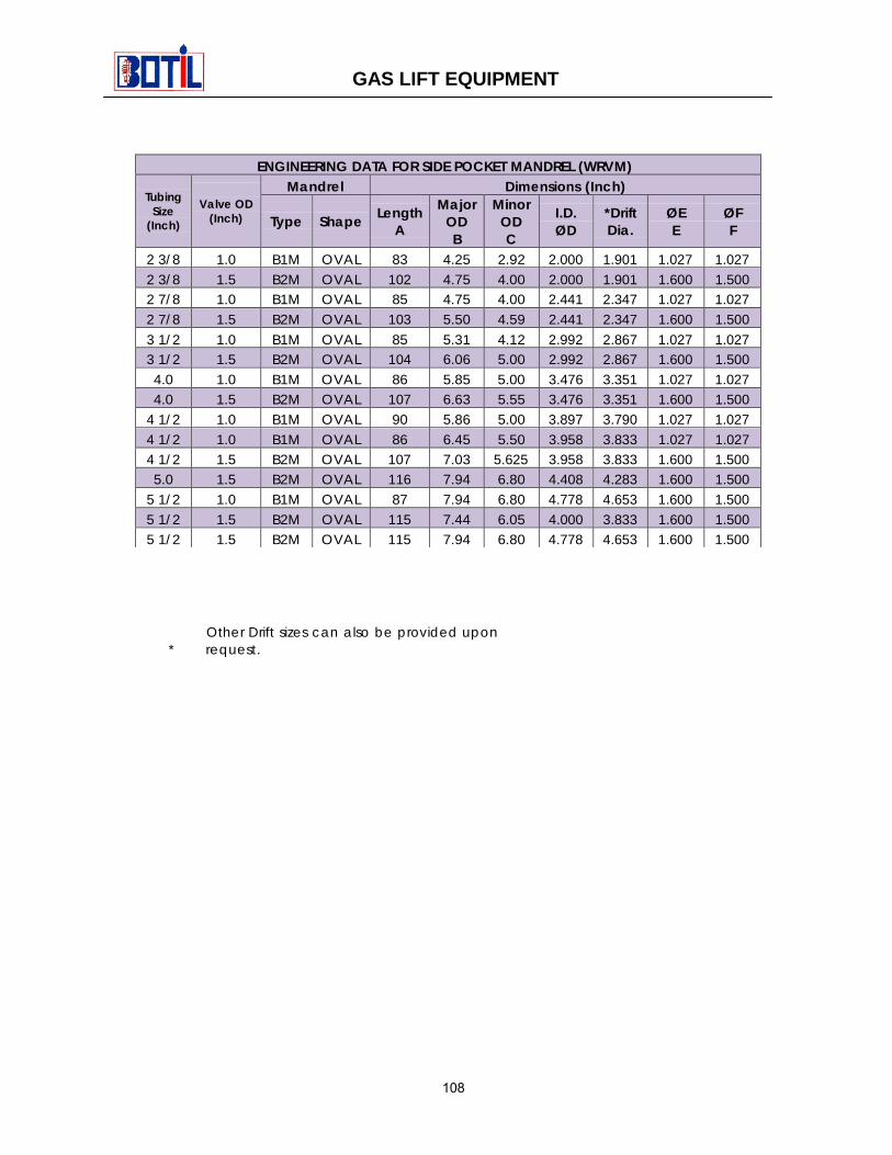
SIDE POCKET MANDREL-CHEMICAL INJECTIONProduct No. BI 820-08
TubingSize
(Inch)Valve OD
(Inch) Type LatchesMajorOD
MinorOD Drift
Dia.UpperSeal
LowerSeal
2 3/8 1.0 B1M-CI GBK-2 4.250 3.410 1.901 1.027 1.0272 3/8 1.5 B2M-CI GRK 4.750 4.500 1.901 1.600 1.5002 7/8 1.0 B1M-CI GBK-2 4.750 4.500 2.347 1.027 1.0272 7/8 1.5 B2M-CI GRK 5.500 5.093 2.347 1.600 1.500
3 1/2 1.0 B1M-CI GBK-2 5.313 4.500 2.867 1.027 1.0273 1/2 1.5 B2M-CI GRK 5.968 5.500 2.867 1.600 1.5004 1/2 1.5 B2M-CI GRK 7.063 6.641 3.833 1.600 1.5005 1/2 1.5 B2M-CI GRK 8.015 7.375 4.653 1.600 1.500
TubingSize
(Inch)
ValveO.D.(Inch)
MandrelType
Test Pressure (PSI)*StandardServices
CorrosiveServices
Internal External Internal External
2 3/8 1.0 B1M-CI 8000 6000 6000 40002 3/8 1.5 B2M-CI 7500 5500 5500 35002 7/8 1.0 B1M-CI 8000 6000 6000 40002 7/8 1.5 B2M-CI 7500 5500 5500 35003 1/2 1.0 B1M-CI 8000 6000 6000 40003 1/2 1.5 B2M-CI 7500 5500 5500 35004 1/2 1.5 B2M-CI 7500 6000 6000 50005 1/2 1.5 B2M-CI 8500 7000 6500 5500
*Test Pressure given are for mandrels made of AISI-4130 (9Cr 1Mo, 13Cr) materialsheat treated for Standard or Corrosive environments. TestPressure may be reduced due to end connection limitations.
GAS LIFT EQUIPMENT
112

GBK-2 (BI 10-01-1000) & GRK (BI 10-25-1000) LATCHES
BOTIL Wireline retrievable latches 1” GBK-2and 1 ½” GRK are designed for installation inG-type pocket profile Side Pocket Mandrels(B1M & B2M). They utilize a locking ring whichis held in position by spring forces. As the latchenters the Side Pocket profile, the locking ringmoves up and into the recessed area of thelatch. When the latch seats, the ring ispositioned in the locking recess of the pocket.To retrieve the latch, a pin is sheared byupward force allowing the locking ring mandrelto move up and out of the way. The ring is thenfreed to disengage from the locking recess asthe valve and latch are retrieved.
GRA LATCH (BI 10-20-1000)
The GRA Latch is a cam style latch used tosecure a 1 ½” O.D. valve (Non- Orienting) ordummy in “MM” and “MMA” Mandrels.
The latch utilizes a rotating spring loaded camto lock in place when the latch reaches therecess in the mandrel receiver pocket. Thelatch also has 2 O-Rings to provide a better topseal and debris barrier. A pin is sheared torelease the locking mechanism allowing thecam to rotate inside the latch housing andpermitting the retrieval of the valve or dummy.
ENGINEERING DATA FOR LATCHES
TypePulling
Neck O.D.(Inch)
RunningNeck O.D.
(Inch)
MaxO.D.
(Inch)
SidePocket
Accessory O.D.(Inch)
RunningTool Pulling Tool
GRK 1.185 0.936 1.787 1.5 RK-1 1 5/8 JDS/PTGGBK-2 0.875 0.75 1.358 1 JK 1 1/4 JDC/MPGRA 1.344 1.359 1.75 1.5 JC-3 2" JDC
GAS LIFT EQUIPMENT
113

E DUMMY VALVE (BI 04-01-1000)RD DUMMY VALVE (BI 04-20-1000)
The RD Dummy Valve is 1 ½” WirelineRetrievable Isolation Tool which is used to sealof the M / TP series Mandrel (B2M) preventingcommunication between the Casing & Tubing.The Dummy valve with the appropriate Latchmay be Wireline installed or retrieved prior to orafter completion for various procedures whichinclude following:
1. To blank off the tubing for productionuntil gas lift valves are required.
2. To allow for pressurizing the tubing invarious procedures.
3. To isolate Tubing & Casing flow duringsingle alternative production and
4. To isolate Tubing & Casing flow for testpurpose during multi-point water or gasinjection floods.
The E Dummy Valve is 1 Wireline RetrievableIsolation Tool which is used to seal of the K /TMP series Mandrel (B1M) preventingcommunication between the Casing & Tubing.The Dummy valve with the appropriate Latchmay be Wireline installed or retrieved prior to orafter completion for various procedures whichinclude following:
1. To blank off the tubing for productionuntil gas lift valves are required.
2. To allow for pressurizing the tubing invarious procedures.
3. To isolate Tubing & Casing flow duringsingle alternative production and
4. To isolate Tubing & Casing flow for testpurpose during multi-point water or gasinjection floods.
ENGINEERING DATA FOR E & RD DUMMY VALVES
TypeNominal
O.D.(Inch)
Packing O.D.(Inch)
Latch orEnd
Conn.
KickOverTool
RunningTool Type
Pulling ToolType
MandrelType
Upper LowerE 1 1 1/32 1 1/32 GBK-2 BK-5 JK 1 1/4 JDC/MP B1M/TMPRD 1 1/2 1 9/16 1 1/2 GRK BM-1 RK-1 1 5/8 JDS/PTG B2M/TP
GAS LIFT EQUIPMENT
114

GAS LIFT EQUIPMENT
BOTIL MODEL BDK-1 DUMMY VALVE (BI 820-11)
BOTIL BDK-1 Dummy Valve serves the same purpose as E Dummy Valve but comes complete with attached top running head & bottom collet latch. The BDK-1 Dummy Valve is 1 Wireline Retrievable Isolation Tool which is used to seal of the K / TMP series Mandrel (B1M) preventing communication between the Casing & Tubing. The Dummy valve with the appropriate Latch may be Wireline installed or retrieved prior to or after completion for various procedures which include following:
1. To blank off the tubing for production until gas lift valves are required. 2. To allow for pressurizing the tubing in various procedures. 3. To isolate Tubing & Casing flow during single alternative production and 4. To isolate Tubing & Casing flow for test purpose during multi-point water or gas injection floods.
114-I
ENGINEERING DATA FOR BDK-1 DUMMY VALVES
Type
Nominal
O.D.
Packing O.D. (Inch)
Latch or End
Conn.
Kick Over Tool
Running
Tool Type
Pulling Tool
Type
Mandrel
Type Upper Lower
BDK-1 1 1 1/32 1 1/32 INTEGRAL OK-5 GA-2 1 1/4 JDC/MP B1M/TMP

‘O’ SERIES ORIFICE VALVESProduct No. BI 820-06
BOTIL O Series 1” & 1-1/2”valves are designed for circulating operationsand provide means for communication between the tubing and thetubing/casing annulus.
FEATURES & BENEFITS Flow capacity determined by orifice sizing. Integral reverse flow check valve provides large flow
capacities. Positive sealing feature of back check valve providesprotection from intrusion of production fluids into casing annulus.
Various orifice materials (SS, Monel, Inconel, tungsten carbide)available to meet application requirements.
Temperature rating of 250º F (121º C) (Standard Service). Standard Neoprene packing with other materials available. Compatible with other manufacturers side Pocket Mandrel
(TMP/TP).
VALVE OPEN
VALVE CLOSED
APPLICATIONSThe Wireline retrievable orifice valves are used to establishcommunication between the tubing & annulus during circulating, gasor fluid injection operations. They are utilized in single point injectioncontinuous flow completions. These valve have no closing functionand are commonly used to control stable injection at the operatingvalve depth.
ENGINEERING DATA FOR ORIFICE VALVESType Nominal
OD (inch)Packing OD
(inch)Port Size
(inch)Latch Or
End Conn.Running
ToolType
PullingToolType
MandrelType
Upper Lower Min. Max.
GRO-40 1 1-1/32 1-1/32 1/8 7/16 GBK-2 JK JDC B1M/B1HO
GRO-20 1-1/2 1-9/16 1-1/2 1/8 51/64 GRK RK-1 JDS B2M/B2HO
GAS LIFT EQUIPMENT
115

GAS LIFT EQUIPMENT
BOTIL BDKO-1 RETRIEVABLE SINGLE POINT INJECTION ORIFICE VALVE (BI 820-10 )
BOTIL BDKO-1 is a single point injection Valve used for continuous flow gas lift production. An integral choke controls the flow of gas through the normally opened valve and into the production conduit. Reverse flow checks are included as an integral part of these valves. The valve containing a replaceable choke with 3/8” Max Port size. Other available port sizes are 1/8”, 3/16”, 1/4”, 5/6” & 3/8”. OPERATION: Injection gas enters the valve through the external parts located between the packing sets. It then travels through the choke, passed a reverse flow check & into the production conduit.
115-I
ENGINEERING DATA
Type
Nominal O.D.
Packing O.D. (Inch)
Latch or End
Conn.
Kick Over Tool
Running
Tool Type
Pulling Tool
Type
Mandrel
Type Upper Lower
BDKO-1 1 1 1/32 1 1/32 INTEGRAL OK-5 GA-2 1 1/4 JDC/MP B1M/TMP

GR-40 INJECTION PRESSUREOPERATED GAS LIFT VALVEProduct No. BI 01-40-1000
BOTIL G Series valve utilizes nitrogencharged bellow configuration designed foreither continuous or intermittent flowapplications. They are especially suitablefor use as unloading and operating valvesin areas where high gas lift pressures areavailable. Since the charge pressure abovethe bellows is affected by temperature, it isimportant that the operating temperaturesat the valve be known. These valves areavailable in Wireline installations.
ADVANTAGES
Vibration protected 3-ply Monel bellow aredesigned to withstand hydrostatic pressureup to 5000 psi. Nitrogen dome charge,acting on the O.D. of the bellow, permitsbellows to expand uniformly withoutstacking, thus prolonging bellow’s life. Themultiple port size availability, make thisvalve series appropriate for a wide range ofoperating conditions. Reversible seat areavailable in several different materials.
ENGINEERING DATA FOR INJECTION PRESSURE OPERATED VALVES
TypeNominal
O.D.(Inch)
Packing O.D.(Inch)
Port Size(Inch) Latch or End
Conn.Running
Tool TypePulling Tool
TypeMandrel
TypeUpper Lower Min. Max.
GR-40 1 1 1/32 1 1/32 1/8 3/8 GBK-2 JK/BC-1 1 1/4 JDC/MP B1M/TMP
GAS LIFT EQUIPMENT
116

GR-20 INJECTION PRESSURE OPERATED GAS LIFT VALVEProduct No. BI 01-20-1000
DESCRIPTION
BOTIL G Series valve utilizes nitrogencharged bellow configuration designed foreither continuous or intermittent flowapplications. They are especially suitablefor use as unloading and operating valvesin areas where high gas lift pressures areavailable. Since the charge pressure abovethe bellows is affected by temperature, it isimportant that the operating temperaturesat the valve be known. These valves areavailable in Wireline installations.
ADVANTAGES
Vibration protected 3-ply Monel bellow aredesigned to withstand hydrostatic pressureup to 5000 psi. Nitrogen dome charge,acting on the O.D. of the bellow, permitsbellows to expand uniformly withoutstacking, thus prolonging bellow’s life. Themultiple port size availability, make thisvalve series appropriate for a wide range ofoperating conditions. Reversible seat areavailable in several different materials.
ENGINEERING DATA FOR INJECTION PRESSURE OPERATED VALVES
TypeNominal
O.D.(Inch)
Packing O.D.(Inch)
Port Size(Inch) Latch or End
Conn.Running
Tool TypePulling Tool
TypeMandrel
TypeUpper Lower Min. Max.
GR-20 1 1/2 1 9/16 1 1/2 1/8 1/2 GRK RK-1/BC-1 1 5/8 JDS/PTG B2M/TP
GAS LIFT EQUIPMENT
117

GAS LIFT EQUIPMENT
MODEL BBK-1 GAS LIFT VALVE (BI 01-10-1000)
DESCRIPTION
BOTIL G Series valve utilizes nitrogen charged bellow configuration designed for either continuous or intermittent flow applications. They are especially suitable for use as unloading and operating valves in areas where high gas lift pressures are available. Since the charge pressure above the bellows is affected by temperature, it is important that the operating temperatures at the valve be known. These valves are available in Wire line installations.
ADVANTAGES
Vibration protected 3-ply Monel bellow are designed to withstand hydrostatic pressure up to 5000 psi. Nitrogen dome charge, acting on the O.D. of the bellow, permits bellows to expand uniformly without stacking, thus prolonging bellow’s life. The multiple port size availability, make this valve series appropriate for a wide range of operating conditions. Reversible seat are available in several different materials.
OPERATING PRINCIPLE
The dome nitrogen charge applied to the external area of the bellows provides the downward force, holding the valve on its seat. This dome pressure is preset at the reference temperature and corrected to operating temperature. The opening forces on the valve are the casing pressure acting on the internal area of the bellows (less the area of the seat) and the tubing pressure acting on the seat area. When the combined Casing & Tubing pressures are sufficient, the valve opens. Once the valve is open, it remains open until the casing pressure is reduced to predetermined closing pressure. The spread (the difference between opening & closing casing pressure) is controlled by the tubing sensitivity of the valve. The larger the seat port area, the more tubing sensitive the valve is.
The BBK-1 Gas Lift Valve is designed with an integral bottom collet latch which locks the valve in the Side Pocket of the Gas Lift Mandrel. Once the valve has locked the Side Pocket of the mandrel, downward jarring causes the collet dog of the latch to engage in the locking recess provided in the side pocket. To pull the Valve, upward jarring is required. The upward jarring shears the brass shear pin securing the shear ring to the latch body. As the BBK-1 valve is pulled upward in the Side Pocket, the shoulder on the Latch body moves out from behind the collet dog. The collet fingers are deflected inward and disengage from the locking recesses of the mandrel pocket. The valve is then free from the mandrel pocket and can be removed from the valve.
117-I

GAS LIFT EQUIPMENT
117-II
ENGINEERING DATA FOR INJECTION PRESSURE OPERATED VALVES
Type Nominal
O.D. (Inch)
Packing O.D. (Inch)
Port Size (Inch) Latch or End
Conn. Running
Tool Type Pulling Tool Type
Mandrel Type
Upper Lower Min. Max.
BBK-1 1 1 1/32 1 1/32 1/8 3/8 INTEGRAL
LATCH GA-2 1 1/4 JDC/MP B1M/TMP

RETRIEVABLE CHEMICAL INJECTIONVALVEProduct No. BI 820-09
BOTIL BCLK & BCLK-1 Chemical injectionvalves are 1” OD valve designed to controlchemicals injected in to the production fluidat valve depth. A Nitrogen charged bellowsprovides the force necessary to maintaineach valve in its normally closed position.The BCLK contain a 3 ply Inconel bellows,which suits this valve for high pressureservice. The BCLK-1 contains a 3 ply Monelbellows and is used for lower pressureapplications. Bellow area is 0.26 squareinch for both valves. Valves contain springloaded reverse flow checks, required GBK-2 top latch & are run in the appropriate B1Mseries mandrels. Port size available for theBCLK & BCLK-1 valves are 1/8” & 3/16”.
OPERATION
BOTIL also design BCLK-2 & BCLK-3Chemical injection valve which are Sidepocket valves designed to controlchemicals injected in to the production fluidat valve depth. An Inconel spring providesthe force necessary to maintain each valvesin its normally closed position. The BCLK-2is for 1” OD & BCLK-3 is for 1-1/2” OD. TheBCLK-2 to utilize a GBK-2 top latch (B1MSPM) & BCLK-3 to utilize a GR serieslatch(B2M SPM). Reverse flow checks areincluded as an integral port of these valves.Port size available for the BCLK-2 & BCLK-3 valves are 1/8” & 3/16”.
Injected chemicals enter the valves fromthe annulus in an open injection system.Chemicals also may enter the valve from aseparate injection line as in a closedinjection system. The hydraulic pressure of
the injected chemicals compresses thebellow/spring & lift the stem tip of the seat &open the valve. Chemicals then flowthrough the valve into the productionconduit.
GAS LIFT EQUIPMENT
118

ENGINEERING DATA
TypeNominal O.D.(Inch)
PackingO.D.(Inch)
Latchor EndConn.
KickOverTool
RunningTool Type
Pulling ToolType
MandrelType
Upper LowerBCLK 1 1 1/32 1 1/32 GBK-2 BK-5 JK 1 1/4 JDC/MP B1M/TMP
BCLK-1 1 1 1/32 1 1/32 GBK-2 BK-5 JK 1 1/4 JDC/MP B1M/TMP
BCLK-2 1 1 1/32 1 1/32 GBK-2 BK-5 JK 1 1/4 JDC/MP B1M/TMP
BCLK-3 1-1/2 1 9/16 1 1/2 GRK BM-1 RK-1 1 5/8 JDS/PTG B2M/TP
GAS LIFT EQUIPMENT
119

KICKOVER TOOLPRODUCT NO. BI 820-01
Introduction and ApplicationThe BOTIL BK-5 & BM-1 kickover toolsare used to install and retrieve 1” and 1-1/2” O.D flow control devices in BOTILB1M/B1HO and B2M/B2HO series sidepocket mandrels.
The kickover tool is lowered into the wellby standard wireline techniques until thetool is below the selected mandrel.As thetool string is raised, the locator finger ofthe kickover tool contacts the top of the
slot in the orienting sleeve in themandrel, and the kick spring pivots thelower section of the kickover tool,thepulling or running tool and the valve intothe kickover position. The orientingsleeve in the mandrel provides positiveinstallation and retrieval of the flowcontrol device by the kickover tool.Oncethe flow control device is installed orretrieved, and the wireline operatorraises the kickover tool the latch springis compressed thus permitting thekickover tool to pass through allmandrels above the one in which thewireline operation was performed.
SPECIFICATIONS FOR TYPE BK-52" 2-1/2" 3" 4-1/2"
FISHNECK OD 1.375 1.375 1.375 1.375MAX OD 1.75 2.063 2.5 3.5LENGTH 72.844 72.844 70.031 70.562TOP PINTHREAD 15/16-10 15/16-10 15/16-10 15/16-10
VALVE SIZE 1"MANDREL
TYPE B1M/B1HO/TMP
SPECIFICATIONS FOR TYPE BM-12-1/2" 3" 4-1/2" 5-1/2"
FISHNECK OD 1.375 1.375 1.375 2.31MAX OD 2.218 2.734 3.71 4.25LENGTH 81.75 81.875 82 78.125TOP PINTHREAD 15/16-10 15/16-10 15/16-10 1 9/16-10
VALVE SIZE 1-1/2"MANDREL
TYPE B2M/TP
GAS LIFT EQUIPMENT
120

G-40 Gas Lift ValveProduct No. BI 02-40-1000
Introduction
The G-40 conventional gas lift valve is a1” O.D pressure operated valve. It canbe used for either continuous orintermitting flow and is installed with areverse check valve on the conventionaltubing retrievable gas lift mandrel. Botilgas lift valve is available in 1/8” to 3/8”Port sizes or as required.
Product Description
The 1” OD (G-40) conventional valvesare Nitrogen charged gas lift valveswhich can be used as an intermittentvalve or a continuous flow valve. N2dome pressure is set in a shop at areference temperature and corrected toan operating depth temperature. The N2charge inside the bellow provides adownward force tending to hold thevalve on its seat.The upward forces necessary to open thevalve are casing pressure acting on thebellow area is less than seat area &tubing pressure acting on the seat area.When these combined pressures aresufficient, the valve will open. Onceopened it will remain open until casingand tubing pressure are reduced to/ orbelow set dome pressure. The differencebetween opening and closing pressure iscalled Spread. It is controlled by tubingpressure sensitivity of the valve. Larger
the seat port area, the more is the tubingsensitive valve.
Valve Specifications:
1. Material: Stainless SteelStandard.
2. Pressure Rating: High range asper API 11V1 1200 Psi andabove.
3. Temperature Rating: 300ºF.
GAS LIFT EQUIPMENT
121

FLOATING SEAT ASSEMBLY
PORTSIZE
FRACTIONEQUIVALE
NT
PARTNUMBER
COMPLETE0.125 1/8” BI 01-10-11140.156 5/32” BI 01-10-12140.188 3/16” BI 01-01-13140.218 7/32” BI-101866-000.250 1/4” BI 01-01-14140.313 5/16” BI 01-01-15140.375 3/8” BI 01-01-1614
STEM TIP ASSEMBLY
PORTSIZE
FRACTIONEQUIVALENT
PART NUMBERCOMPLETE
0.125 1/8” BI 01-10-1111
0.156 5/32” BI 01-10-1211
0.188 3/16” BI 01-10-1311
0.218 7/32” BI-101885-00
0.250 1/4” BI 01-10-1411
0.313 5/16” BI 01-10-1511
0.375 3/8” BI 01-10-1611
TECHNICAL DATA
AvailablePort Sizes
I. D.(Inches)
(Ab)Effective
Bellows Area(SquareInches)
Area of Port withBevel (Av)
(Square Inches)Av/Ab
(1-Av/Ab)
TEF = Av/Ab1-Av/Ab
Tubing EffectFactor
1/8” 0.31 0.0129 0.042 0.958 0.0435/32” 0.31 0.0201 0.065 0.935 0.0693/16” 0.31 0.0291 0.094 0.906 0.1047/32” 0.31 0.0395 0.127 0.873 0.1451/4” 0.31 0.0511 0.164 0.836 0.1965/16” 0.31 0.0792 0.255 0.745 0.3423/8” 0.31 0.1134 0.365 0.635 0.575
ENGINEERING DATAMaximum outsideDiameter
1.000 inches
Overall length 13.53”Connecting Thread ײ1/2 -14 NPTMandrel seriesrequired
(B Series) JRMandrel
Check Valve G-40/GCF-40
GAS LIFT EQUIPMENT
122

G-20 Gas Lift ValveProduct No. BI 02-20-1000
The G-20 conventional gas lift valveis a 1-1/2” O.D Pressure operatednitrogen charged valve. It can beused for either continuous orintermitting flow and is installed witha reverse check valve on theconventional tubing retrievable classmandrels. Port sizes available 1/8”to1/2” or as required. N2 domepressure is set in a shop at areference temperature and correctedto an operating depth temperature.The N2 charge inside the bellowprovides a downward force tendingto hold the valve on its seat. Theupward forces necessary to open thevalve are casing pressure acting onthe bellow area is less than seatarea & tubing pressure acting on theseat area. When these combinedpressures are sufficient, the valvewill open. Once opened it will remainopen until casing and tubingpressure are reduced to/ or belowset dome pressure. The differencebetween opening and closingpressure is called Spread. It iscontrolled by tubing pressuresensitivity of the valve. Larger theseat port area, the more is the tubingsensitive valve.
Valve Specifications:1. Material: Stainless
Steel Standard.2. Pressure Rating: High
range as per API 11V11200 Psi and above.
3. Temperature Rating:300ºF.
GAS LIFT EQUIPMENT
123

STEM TIP ASSEMBLY
PORT
SIZE
FRACTION
EQUIVALENT
PARTNUMBER
COMPLETE
0.125 1/8” BI 02-20-12120.156 5/32” BI-101978-000.188 3/16” BI 02-20-13120.218 7/32” BI-101979-000.250 1/4” BI 02-20-14120.313 5/16” BI 02-20-15120.375 3/8” BI 02-20-16120.438 7/16” BI 02-20-17120.500 ½” BI-107131-00
FLOATING SEAT ASSEMBLY
PORTSIZE
FRACTION
EQUIVALENT
PARTNUMBER
COMPLETE
0.125 1/8” BI 01-20-12150.156 5/32” BI-101980-000.188 3/16” BI 01-20-13150.218 7/32” BI-101981-000.250 1/4” BI 01-20-14150.313 5/16” BI 01-20-15150.375 3/8” BI 01-20-16150.438 7/16” BI 01-20-17150.500 ½” BI-107132-00
TECHNICAL DATA
AvailablePort
Sizes
AbEffectiveBellows
Area(SquareInches)
Area ofPortwith
Bevel(Av)
(SquareInches)
Av/Ab (1-Av/Ab)
TEF =Av/Ab
1-Av/AbTubingEffectFactor
1/8” 0.77 0.0129 0.017 0.983 0.0175/32” 0.77 0.0201 0.026 0.974 0.0273/16” 0.77 0.0291 0.038 0.962 0.0407/32” 0.77 0.0395 0.051 0.949 0.0541/4” 0.77 0.0395 0.067 0.933 0.072
5/16” 0.77 0.0792 0.104 0.896 0.1163/8” 0.77 0.1134 0.148 0.852 0.174
7/16” 0.77 0.1532 0.201 0.799 0.252½” 0.77 0.1955 0.254 0.746 0.342
ENGINEERING DATAMaximumoutside Diameter
1.500”
Overall length 14-5/16”ConnectingThread
½” –14 NPT
Mandrel seriesrequired
(C Series)SR Mandrel
Check Valve G-20/GCF-20
GAS LIFT EQUIPMENT
124

G-40 CHECK VALVEProduct No. BI 02-90-1000
G-40 check valves are used with G-40conventional gas lift valve to protect thecasing from backflow, allowing thetubing to be pressurizing in variousprocedures, and prevent anycommingling of fluids in dualinstallation. The conventional checkassemblies utilizes the same metal tometal seal as well as metal dart to softhy-car pad seal as does the retrievablevalve checks. The G-40 check is avelocity type check requiring flowpressure to force the dart on seat but isalso available in a normally closedvariation with a spring attachment.G-40 check valves are of the samedesign as the G-20 but designed for usedwith the 1” conventional G-40 valve thedart, seal and pad are of the same designas the K series, retrievable valves.GCF-40 is a reverse flow check with allthe characteristics of the G-40 check but
designed for use with the 1”conventional casing flow valve.
CONVENTIONAL CHECK VALVESPECIFICATIONS
ModelCheckO.D
LengthEquivalentPort Size
ConnectingThread
G-40 1" 3- 9/16" 5/16" 1/2" NPT
GAS LIFT EQUIPMENT
125

G-20 CHECK VALVEProduct No. BI 02-70-1000
G-20 Check valves are used with G-20 conventional gas lift valve toprotect the casing from backflow,allow for pressurizing the tubing invarious procedures, and prevent anycommingling of flow in dualinstallation. The conventional checkassemblies utilize the same metal tometal seal as well as metal dart tosoft hy – car pad seal as does theretrievable valve checks. The G-20check is a velocity type checkrequiring flow pressure to force thedart on seal but is also available in anormally closed variation with aspring attachment.
G-20 is a reverse flow check with allthe characteristics of the G-20 checkbut designed for use with the 1 ½”conventional casing flow valve.
CONVENTIONAL CHECK VALVE SPECIFICATIONS
ModelCheckValveO.D
Length EquivalentPort Size
ConnectingThread
G-20 1- 1/2" 4 -3/4" 9/16" 1/2" NPT
GAS LIFT EQUIPMENT
126

MODEL ‘B’ CONVENTIONAL GASLIFT MANDRELProduct No. BI 06-115-601
The Model ‘B’ mandrels aredesigned to accept the 1”conventional G-40 pressureoperated gas lift valve and G-40tubing flow check Valve. TheMandrels are manufactured with sideguards to protect the valve whenrunning or pulling the tubing string.
These mandrels are available invarious tubing grades such as J-55,N-80, L-80, P-110 & other grades ofmaterial as per customerrequirement.
ENGINEERING DATA
Maximum O.D, thread Connection & other PPF can be furnished as required.
TubingSizeInch
Max.O.D.Inch
I.D.Inch
LengthFt.
2-3/8 3.781 1.995 4
2-7/8 4.396 2.441 4
2-7/8 4.396 2.259 4
3-1/2 5.062 2.992 4
GAS LIFT EQUIPMENT
127
botilmail
Text Box
BOTIL MODEL `B' GAS LIFT MANDREL

MODEL ‘C’ CONVENTIONAL GASLIFT MANDRELProduct No. BI 06-535-501
The Model ‘C’ mandrels aredesigned to accept the 1-1/2”conventional G-20 pressureoperated gas lift valve and G-20tubing flow check Valve. TheMandrels are manufactured with sideguards to protect the valve whenrunning or pulling the tubing string.
These mandrels are available invarious tubing grades such as J-55,N-80, L-80, P-110 & other grades ofmaterial as per customerrequirement.
ENGINEERING DATA
Maximum O.D, thread Connection & other PPF can be furnished as required.
TubingSizeInch
Max.O.D.Inch
I.D.Inch
LengthFt.
2-3/8 4.375 1.995 4
2-7/8 4.929 2.441 4
2-7/8 4.929 2.259 4
3-1/2 5.655 2.992 4
4-1/2 6.875 3.958 4
GAS LIFT EQUIPMENT
128
botilmail
Text Box
BOTIL MODEL `C' GAS LIFT MANDREL
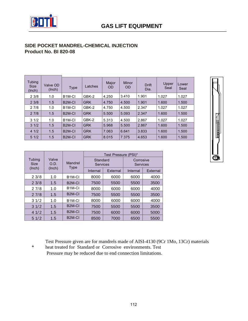
BOTIL JK RUNNING TOOLProduct No.- BI 820-04
PURPOSE:Running “BK/GBK-2 side pocket
mandrel latches assembled to subsurfacecontrols.
DESCRIPTION:The “JK” Running tools are simple in
design, consisting of one part. The insideis machined with two different insidediameters allowing the running tool toshoulder on the side pocket mandrel latchbeing run. The upper portion of the bodyhas a set of 1/8” shear pin holes on theouter circumference to permit pinningthe running tool to the side pocket controllatch. The “JK” running tool is run inconjunction with the appropriate kickover tool.
Nominal size 1.00”Upper threadconnection
0.938” – 10 UN
Max O.D. 1.33”Fishneck Size 1.188”
GAS LIFT EQUIPMENT
129

BOTIL RK-1 RUNNING TOOLProduct No. - BI 820-05
Purpose
Running “RK-1/RKP” side pocketmandrel latches assembled to sub surfacecontrols.
DescriptionThe “RK” running tools are simple indesign, consisting of one part. The insideis machined with two different insidediameters allowing the running tool toshoulder on the side pocket mandrel latchbeing run. The upper portion of the bodyhas a set of 1/8” shear pin holes on theouter circumference to permit pinning therunning tool to the side pocket controllatch. The “RK” running tool is run inconjunction with the appropriate kickover tool.
Nominal Size 1.50”Upper ThreadConnection
0.938”-10 UN
Max. O.D. 1.43”Fishneck Size 1.188”
GAS LIFT EQUIPMENT
130

BOTIL MODEL”JDC/JDS”PULLING TOOLProduct No. BI 811-90 & BI 811-97
The “JDC/JDS” Pulling Tool is a wirelineservice tool designed to removeretrievable subsurface devices withexternal fishing necks from well. Thistool has collet-type dogs with largelatching area. It is also available withdifferent length cores which make thereach of the tool adaptable to retrievesubsurface devices with fishing necks ofdifferent lengths.
The “JDC/JDS” Pulling Tool utilizes thetop sub which is made up to the skirt ofthe tool. The dogs, which are mounted onthe skirt, are inserted into the verticalopenings in the skirt. The “JDC/JDS”Series Pulling Tool can be released, ifnecessary from the retrievable device bydownward jarring. In the Pulling Toolnomenclature, the second letter is used todesignated the direction of shear release.A”JDC/JDS” is a “jar down” release tool.The third letter designates core lengthwith a “C” being a “long” core and an “S”core being a “short” core.
GAS LIFT EQUIPMENT
131

SIZE TYPE
TOENGAGEFISHINGNECKO.D.
REACH
MAXO.D.
TOPTHREADCONNECTION
1 1/4” JDC .875” 1.937” 1.281” 15/16-101 3/8” JDC 1.000” 1.875” 1.375” 15/16-101 1/2” JDC 1.187” 1.093” 1.422” 15/16-101 1/2” JDS 1.187” 1.843” 1.422” 15/16-101 1/2” JUC 1.187” 1.093” 1.422” 15/16-101 1/2” JUS 1.187” 1.843” 1.422” 15/16-101 5/8” JDC 1.187” 1.093” 1.625” 15/16-10
2” JDC 1.375” 1.437” 1.859” 15/16-102” JDS 1.375” 2.125” 1.859” 15/16-102” JUC 1.375” 1.437” 1.859” 15/16-102” JUS 1.375” 2.125” 1.859” 15/16-10
2 1/2” JDC 1.750” 1.312” 2.250” 15/16-102 1/2” JDS 1.750” 2.187” 2.250” 15/16-102 1/2” JUC 1.750” 1.312” 2.250” 15/16-102 1/2” JUS 1.750” 2.187” 2.250” 15/16-10
3” JDC 2.312” 1.437” 2.796” 1 1/16-103” JDS 2.312” 2.125” 2.796” 1 1/16-103” JUC 2.312” 1.437” 2.796” 1 1/16-103” JUS 2.312” 2.125” 2.796” 1 1/16-104” JDC 3.125” 2.312” 3.750” 1 1/16-104” JUC 3.125” 2.312” 3.750” 1 1/16-10
GAS LIFT EQUIPMENT
132