1. Final Report English - JICAopen_jicareport.jica.go.jp/pdf/12026753_01.pdf · Table 3.2-1 Housing...
68
Republic of Mauritius Mauritius Wastewater Management Authority Republic of Mauritius Technical Assistance for Grand Baie Sewerage Project Phase 1-B Final Report Volume1: Main Report March 2011 Japan International Cooperation Agency (JICA) NIPPON KOEI CO.,LTD. (NK) No. 11-002 CR (3) AFD
Transcript of 1. Final Report English - JICAopen_jicareport.jica.go.jp/pdf/12026753_01.pdf · Table 3.2-1 Housing...

Republic of Mauritius
Mauritius Wastewater Management Authority
Republic of Mauritius
Technical Assistance
for
Grand Baie Sewerage Project Phase 1-B
Final Report
Volume1: Main Report
March 2011
Japan International Cooperation Agency (JICA)
NIPPON KOEI CO.,LTD. (NK)
No.
11-002
CR (3)
AFD


Republic of Mauritius
Mauritius Wastewater Management Authority
Republic of Mauritius
Technical Assistance
for
Grand Baie Sewerage Project Phase 1-B
Final Report
Volume1: Main Report
March 2011
Japan International Cooperation Agency (JICA)
NIPPON KOEI CO.,LTD. (NK)
No.
11-002
CR (3)
AFD


March 2011
Mr. Kenzo OOSHIMA
Senior Vice-President
Japan International Cooperation Agency
Dear Sir,
Letter of Transmittal
We are very pleased to submit herewith the Final Report of ”The Study on Technical Assistance
for Grand Baie Sewerage Project Phase 1-B for the Republic of Mauritius”
The Study was carried out by NIPPON KOEI CO., LTD. Under the contract with your Agency
for the four-month period from December 2010 to March 2011.
The study is one of technical assistance which aims to promote ODA loan project of detail
design and construction smoothly, and to enhance project result through topographic survey and
inflow & infiltration mitigation survey. The study proposed main sewer route in accordance
with topographic condition, considering number of pumping station and pumping head.
Effective wastewater collection in low lying area and customer information, which is required in
operation stage, are also proposed. Technical and institutional plan of inflow and infiltration
mitigation is provided for sewerage facility management.
Finally, we genuinely wish that the report will be transferred to sewerage system development
of Mauritius.
Yours very sincerely,
Yakuro INOUE
Team Leader,
Technical Assistance for Grand Baie Sewerage Project Phase 1-B
for the Republic of Mauritius


Republic of Mauritius Technical Assistance for Grand Baie Sewerage Project Phase 1-B
Final Report
NIPPON KOEI CO.,LTD.
Republic of Mauritius
Technical Assistance for Grand Baie Sewerage Project Phase 1-B
Volume-1 Main Report
TABLE OF CONTENTS PROJECT SITE MAP
SUMMARY __________________________________________________________________ S-1
1. Objectives of The Survey ............................................................................................................ S-1
2. Study Result ................................................................................................................................ S-1
3 Conclusion .................................................................................................................................. S-12
CHAPTER 1 INTRODUCTION _______________________________________________ 1-1
1.1 Background of The Survey ..................................................................................................... 1-1
1.2 Objectives of the Study .......................................................................................................... 1-2
1.3 Implementing Organization and Survey Area ........................................................................ 1-3
1.4 Points to be Noted When Implementing the Survey .............................................................. 1-5
CHAPTER 2 STUDY METHODOLOGY _______________________________________ 2-1
2.1 Study Schedule ....................................................................................................................... 2-1
2.2 Staffing ................................................................................................................................... 2-2
CHAPTER 3 TOPOGRAPHIC SURVEY _______________________________________ 3-1
3.1 Street Survey .......................................................................................................................... 3-1
3.1.1 Methodology of Street Survey (Center Line and Longitudinal Profile) .......................... 3-1
3.1.2 Result of Street Survey .................................................................................................... 3-3
3.1.3 Application of Surveyed Result ...................................................................................... 3-4
3.2 Housing Lot Survey ............................................................................................................... 3-6
3.2.1 Methodology of Housing Lot Survey .............................................................................. 3-6
3.2.2 Result of Housing Survey ..............................................................................................3-11
3.2.3 Application of Surveyed Result .................................................................................... 3-12
3.3 Sewer Main Route Survey .................................................................................................... 3-14
3.3.1 Issues on the Original Plan ............................................................................................ 3-14
3.3.2 Alternative Plan ............................................................................................................. 3-18
3.3.3 The Requirement of Road Development Authority....................................................... 3-20
3.3.4 Conclusion ..................................................................................................................... 3-21
3.4 Local Sewer Plan .................................................................................................................. 3-22

Republic of Mauritius Technical Assistance for Grand Baie Sewerage Project Phase 1-B
Final Report
NIPPON KOEI CO.,LTD.
3.4.1 Sewerage Planning Area ................................................................................................ 3-22
3.4.2 Wastewater Collection in Low-Lying Area ................................................................... 3-25
3.4.3 Local Sewer Plan ........................................................................................................... 3-30
3.4.4 Conclusions ................................................................................................................... 3-30
CHAPTER 4 GEOLOGICAL SURVEY AND INJECTION WELL SURVEY _________ 4-1
4.1 Introduction ............................................................................................................................. 4-1
4.1.1 Collecting Data for the Injection Well Survey ................................................................ 4-1
4.1.2 Topographic and Geological Conditions ......................................................................... 4-4
4.2 Core Hole Survey .................................................................................................................... 4-6
4.2.1 General ............................................................................................................................ 4-6
4.2.2 Results of the Cole Hole Survey ..................................................................................... 4-9
4.2.3 Analysis ..........................................................................................................................4-11
4.2.4 Conclusion ..................................................................................................................... 4-14
4.3 Injection Well Survey ........................................................................................................... 4-14
4.3.1 General .......................................................................................................................... 4-14
4.3.2 Results of the Injection Well Survey ............................................................................. 4-20
4.3.3 Analysis ......................................................................................................................... 4-26
4.3.4 Conclusion ..................................................................................................................... 4-27
CHAPTER 5 INFLOW AND INFILTRATION SURVEY __________________________ 5-1
5.1 Outline of Inflow and Infiltration Mitigation ......................................................................... 5-1
5.2 Field Survey ........................................................................................................................... 5-2
5.3 Inflow and Infiltration Mitigation Plan .................................................................................5-11
5.4 Technical Assistance Meeting on Inflow and Infiltration Mitigation ................................... 5-20
CHAPTER 6 CONCLUSION _________________________________________________ 6-1
6.1 Topographical Survey ............................................................................................................ 6-1
6.2 Land Acquisition and Consultation with Authorities ............................................................. 6-1
6.3 Geological Survey .................................................................................................................. 6-2
6.4 Injection Well Survey ............................................................................................................. 6-2
6.5 Inflow and Infiltration Mitigation .......................................................................................... 6-3
APPENDIX
1 Land Acquisition Act
2 Location of Classified Road
3 Seawater Intrusion

Republic of Mauritius Technical Assistance for Grand Baie Sewerage Project Phase 1-B
Final Report
NIPPON KOEI CO.,LTD.
4 Sewer Plan Layout
5 Inflow and Infiltration Mitigation Plan
Volume-2:Report of Topographic Survey
1. Report of Survey
2. Street Survey
2D Diagram and Sewer Layout Plan
Longitudinal Profiles
3. Housing Lot Survey (Household Inventory)
Volume-3:Report of Geological Survey
1. Report of Geological Survey (Pumping Station)
2. Report of Borehole Injection Test

Republic of Mauritius Technical Assistance for Grand Baie Sewerage Project Phase 1-B
Final Report
NIPPON KOEI CO.,LTD.
List of Tables
Table 1.1-1 Sewerage Project Phase1-A & Phase1-B ................................................................... 1-2
Table 1.4-1 Points of The Study .................................................................................................... 1-6
Table 1.4-2 Stepwise I/I Rehabilitation ......................................................................................... 1-8
Table 2.1-1 Study Itinerary ........................................................................................................... 2-1
Table 2.2-1 Assignment Schedule ................................................................................................. 2-3
Table 3.2-1 Housing Lot Survey Scope ........................................................................................ 3-6
Table 3.2-2 Information Collected from the Housing Lot Survey ................................................ 3-9
Table 3.2-3 Prototype of House Inventory (1/2) ......................................................................... 3-12
Table 3.2-3 Prototype of House Inventory (2/2) ......................................................................... 3-13
Table 3.3-1 Advantages of the Proposed Plan............................................................................. 3-18
Table 3.4-1 Role of Sewerage System ........................................................................................ 3-31
Table 4.1-1 Past Reports ............................................................................................................... 4-1
Table 4.1-2 Existing Boreholes Drilled in 1999 ............................................................................ 4-1
Table 4.1-3 Outline of the Survey for Existing Boreholes ............................................................ 4-2
Table 4.1-4 Result of the Injection Tests in 2009 .......................................................................... 4-3
Table 4.2-1 Location of Core Holes .............................................................................................. 4-6
Table 4.2-2 Depth of Sample for UCS Tests ................................................................................. 4-7
Table 4.2-3 Analyzing Techniques of Chemical Parameters at the Laboratory ............................ 4-8
Table 4.2.4 UCS Test .................................................................................................................. 4-10
Table 4.2-5 Result of Water Quality Tests for the Core Holes .................................................... 4-11
Table 4.2-6 Shape Coefficients ................................................................................................... 4-12
Table 4.2-7 Internal Frictional Angle (φ) .................................................................................... 4-12
Table 4.2-8 Bearing Capacity Factor (Nc, Nr, Nq) ..................................................................... 4-12
Table 4.2-9 Cohesion (c) Estimated by N-value ......................................................................... 4-13
Table 4.2-10 Cohesion (c) Estimated by UCS .............................................................................. 4-13
Table 4.2.11 Allowable Bearing Capacity (qa) .............................................................................. 4-14
Table 4.3.1 Location of the Injection Wells ................................................................................ 4-15
Table 4.3-2 Result of Step Tests for BH-4 and BH-5 .................................................................. 4-22
Table 4.3-3 Result of Constant Rate Pumping Tests for BH-4 and BH-5 ................................... 4-24
Table 4.3-4 Result of Water Quality Tests for BH-4 and BH-5 .................................................. 4-26
Table 5.2-1 Flow Rate of Pumping Stations (1/3) ......................................................................... 5-8
Table 5.2-1 Flow Rate of Pumping Stations (2/3) ......................................................................... 5-9
Table 5.2-1 Flow Rate of Pumping Stations (3/3) ....................................................................... 5-10
Table 5.3-1 Overall of Inflow & Infiltration Mitigation Plan ...................................................... 5-11

Republic of Mauritius Technical Assistance for Grand Baie Sewerage Project Phase 1-B
Final Report
NIPPON KOEI CO.,LTD.
List of Figures
Figure 1.3-1 Grand Baie Sewerage Project Phase 1-A, Phase 1-B and Phase 2 .......................... 1-4
Figure 1.4-1 Wastewater Treatment ............................................................................................. 1-5
Figure 1.4-2 Change of I/I in Japan .............................................................................................. 1-7
Figure 1.4-3 I/I of Separate Sewer ............................................................................................... 1-8
Figure 3.1-1 Survey Situation ....................................................................................................... 3-2
Figure 3.1-2 Street Survey Route .................................................................................................. 3-3
Figure 3.1-3 Low-lying Area and Sewer Main Alternative in Petit Raffray ................................. 3-5
Figure 3.1-4 Sewer Main Occupying Private Property (Farm land) in The Vale ........................ 3-5
Figure 3.2-1 Request for Cooperation(Communiqué) .................................................................. 3-7
Figure 3.2-2 Household Interview (WMA Staff) .......................................................................... 3-8
Figure 3.2-3 Individual Housing Lot Survey Form .................................................................... 3-10
Figure 3.2-4 Housing Map in Point aux Canonniers .................................................................... 3-11
Figure 3.3-1 Original Main Sewer Route Plan ............................................................................ 3-14
Figure 3.3-2 Contour Map(1/2) ............................................................................................. 3-16
Figure 3.3-2 Contour Map (2/2) .................................................................................................. 3-17
Figure 3.3-3 Alternative Study on Pereybere and Cap Malheureux,
Petit Raffray, The Vale and Sottise ......................................................................... 3-19
Figure 3.3-4 Classified Road of Road Development Authority .................................................. 3-20
Figure 3.3-5 Multi-pump Conveyance Sewer ............................................................................. 3-21
Figure 3.3-6 H2S Corrosion ........................................................................................................ 3-22
Figure 3.4-1 Isolated Houses ...................................................................................................... 3-24
Figure 3.4-2 Low-Lying Housing Lot in Coastal Area and Backyard Sewerage ........................ 3-26
Figure 3.4-3 Low-Lying Houses in Hollow Area and Condominial Sewer System ................... 3-27
Figure 3.4-4 Houses Facing Beach along the Backside of Hills and
the Required Drainage Pump ................................................................................. 3-28
Figure 3.4-5 Low-Lying Houses along Sloping Roads and Communal Discharge Pump .......... 3-29
Figure 3.4-6 Job Stage of House Connection on Survey, Design and Construction ................... 3-32
Figure 4.1-1 Result of Step Pumping Test in 1999 ....................................................................... 4-2
Figure 4.1-2 Result of Injection Test in 2009 ................................................................................ 4-3
Figure 4.1-3 (a) Geological Location of the Island of Mauritius in the Indian Ocean Region;
and (b) Simplified Geological Map of Mauritius ..................................................... 4-4
Figure 4.1-4 (a) Columnar Joints Exposed on the Beachside; (b) Ball-like Porous Basalt;
(c) Basalt Split along Platy and Columnar Joints; (d) Thin Colluviums on the
Basaltic Rocks. ......................................................................................................... 4-5
Figure 4.2-1 Location Map of Core Holes .................................................................................... 4-6

Republic of Mauritius Technical Assistance for Grand Baie Sewerage Project Phase 1-B
Final Report
NIPPON KOEI CO.,LTD.
Figure 4.2-2 (a) Drilling the Core Hole by Rotary Boring Machine (b) Conducting SPT;
(c) Installation of Standpipes for Groundwater Level Gauge; and
(d) Slotted Tube for Standpipes. ............................................................................... 4-8
Figure 4.2-3 Summarized Columnar Section ................................................................................ 4-9
Figure 4.3-1 Location of the Injection Wells and WWTP ........................................................... 4-16
Figure 4.3.2 (a) Drilling of BH-4 by Down-the-hole Hammer; (b) Drilling of BH-5 by
Down-the-hole Hammer; (c) Down-the-hole Hummer Bit and Rods; (f) Bit with
diameter of 300mm; (e) Drilling with water at BH-4; and (f) Drilling at BH-5. ... 4-17
Figure 4.3-3 (a) Casing of PVC Pipe with 300mm Diameter; (b) Slotted PVC pipes;
(c) Installing the Casing into the Borehole; (d) Installed Casing with Blue Filter;
(e) Cleaning by Airlift; (f) Discharge of Airlift ...................................................... 4-18
Figure 4.3-4 (a) Pump for Step Test; (b) Measuring the Yield .................................................... 4-19
Figure 4.3-5 Measuring Groundwater Level ............................................................................... 4-20
Figure 4.3-6 Summarized Columnar Section .............................................................................. 4-21
Figure 4.3-7 Result of Step Test for BH-4 .................................................................................. 4-22
Figure 4.3-8 Correlation between Yield (Q) and Drawdown (s) of BH-4 ................................... 4-23
Figure 4.3-9 Result of Step Test for BH-5 .................................................................................. 4-23
Figure 4.3-10 Correlation between Yield (Q) and Drawdown (s) of BH-5 ................................... 4-24
Figure 4.3-11 Result of the Constant Rate Pumping Test for BH-4 .............................................. 4-25
Figure 4.3-12 Result of the Constant Rate Pumping Test for BH-5 .............................................. 4-25
Figure 4.3-13 Schematic Profile of the site ................................................................................... 4-27
Figure 5.2-1 Existing Sewerage System in Grand Baie (1/3) ....................................................... 5-3
Figure 5.2-1 Existing Sewerage System in Grand Baie (2/3) ....................................................... 5-4
Figure 5.2-1 Existing Sewerage System in Grand Baie (3/3) ....................................................... 5-5
Figure 5.2-2 Flow Rate of Pumping Station ................................................................................. 5-7
Figure 5.3-1 Infiltration and Rainwater Tank .............................................................................. 5-13
Figure 5.3-2 Stormwater Reservoir in Public Space ................................................................... 5-14
Figure 5.3-3 Stormwater Reservoir ............................................................................................. 5-14
Figure 5.3-4 I/I Mitigation during the Construction stage (1/2) ................................................. 5-15
Figure 5.3-4 I/I Mitigation during the Construction stage (2/2) ................................................. 5-16
Figure 5.3-5 Diversion Facility ................................................................................................... 5-18
Figure 5.3-5 Sticker: Authorized Plumber One-stop Shop of Wastewater-related Matter .......... 5-19

Republic of Mauritius Technical Assistance for Grand Baie Sewerage Project Phase 1-B
Final Report
NIPPON KOEI CO.,LTD.
Abbreviations
AFD Agence Française de Développement
AfDB African Development Bank
BH Borehole
C/P Counter Part
CAD Computer Aided Design
COD Chemical Oxygen Demand
CWA Central Water Authority
DF/R Draft Final Report
DI Ductile Iron
EBDR European Bank of Development and Reconstruction
EIA Environmental Impact Assessment
F/R Final Report
F/S Feasibility Study
GOM Government of Mauritius
GPS Global Positioning System
HDPE High Density Polyethylene
I/I Inflow and Infiltration
IC/R Inception Report
MS Mini Pumping Station, Manhole Type Pumping Station
NEAP1 First National Environmental Action Plan
NSP National Sewerage Programme
OJT On The Job Training
ORP Oxygen Reduction Potential
PE Polyethylene
PS Pumping Station
PVC Polyvinyl chloride
RDA Road Development Authority
SCADA Supervisory Control and Data Acquisition
STP Sewerage Treatment Plant
TBM Temporary Benchmark
TDS Total Dissolved Solids
TOR Terms of Reference
WB World Bank
WMA Wastewater Management Authority
WRU Water Resources Unit
WWTP Wastewater Treatment Plant


Republic of Mauritius Technical Assistance for Grand Baie Sewerage Project Phase 1-B
Final Report
NIPPON KOEI CO.,LTD.
Project Site Map
Source: Preparatory Survey for Grand Baie Sewerage Project in Republic of Mauritius
【Study Area(Phase1-A)】
Inflow and Infiltration Survey
【Study Area(Phase1-B)】
Topographic Survey and
Geological Survey
【Study Area】
Injection Well Survey
Source: http://www.geocities.jp/mskm2005/mauritius.html

Republic of Mauritius Technical Assistance for Grand Baie Sewerage Project Phase 1-B
Final Report
S-1 NIPPON KOEI CO.,LTD.
SUMMARY
1. Objectives of The Survey
The study supports the technical assistance program aiming Grand Baie Wastewater Project to be
more efficient. The study aims to conduct the following in advance prior to detailed design:
1) Topographic and geological survey in the area of Sewerage Project Phase 1-B (route survey,
individual housing lot survey, and geological survey)
To collect technical information for further study of detailed design
2) Borehole investigation at wastewater effluent injection
To collect technical information for further study of detailed design
3) Inflow/Infiltration (I/I) survey at existing sewerage service area of Phase 1-A
To execute survey and provide technical transfer through seminars
Proposal on applying I/I mitigation measures on Phase1-B Project
2. Study Result
(1) Topographic Survey
Street survey was executed with sufficient accuracy in order to prevent obstacles for global
positioning system (GPS) digital terrain model and electro-optical distance measurement are
combined. Street survey smoothly provided, on the beginning stage, contour maps which
supplied valuable information to housing lot survey and sewer layout plan. This study was the
first to develop contour map for Grand Baie. On housing lot survey, cadastral record and
household information were not established, and customer information of Central Water
Authority (CWA) and Energy Services Division of the Ministry of Energy and Public Utilities
could not identify address and house owners. The study interviewed each household and collected
information as described in Table S-2. Since housing lot survey is delicate on privacy, interviews
were executed through community awareness of radio and local administration office.
Street and reconnaissance surveys detected topographic information of low-lying area and
longitudinal street profile.

Republic of Mauritius Technical Assistance for Grand Baie Sewerage Project Phase 1-B
Final Report
S-2 NIPPON KOEI CO.,LTD.
Table S-1 Housing Lot Survey Scope
Object Amount Scope
Low-Lying Area
Housing Lot
1,112 houses (900 planned) 810 at ground level surveyed
・ Location of wastewater discharge facilities ・ Obstacles of house connection ・ Building lay-out ・ Elevation
Others 5,626 houses
Sewer route determined by aerial photo (check elevation of house connection)
* Detailed design executes housing lot survey
Total 6,738 houses (4,400 houses planned)
Table S-2 Information Collected from Housing Lot Survey
Collected Information Survey Team Purpose of the Information Acquisition
Address WMA Basic customer information
Owner WMA Basic customer information
Phone Number WMA Basic customer information
CWA Account Number WMA Basic customer information
(For fare collection)
Front Road Proprietary JICA Study Team Basic information for detailed design
(To check the necessity of wayleave)
Location of Wastewater
Discharge Facilities
JICA Study Team Basic information for detailed design
(To decide location of house connection)
Location of Other Utility
Service Line
JICA Study Team Basic information for detailed design
(To decide location of house connection)
Length of House
Connection
JICA Study Team Basic information for detailed design
(To calculate the amount of construction works)
Elevation of Front Road JICA Study Team
(GPS Survey)
Basic information for detailed design
(To decide the pipe depth)
Lowest Elevation in
Housing Lot
JICA Study Team
(GPS Survey)
Basic information for detailed design
(To decide the pipe depth)
Topographic survey contributed to reduce three pumping stations (PS) and manhole type
pumping stations (MS) including 25 m pump head as seen on Table S-3.
Sewer layout plan showing sewer line with MS and PS and house connection was provided.
House connection is decided through aerial photo, street survey and interviews on housing
facilities.
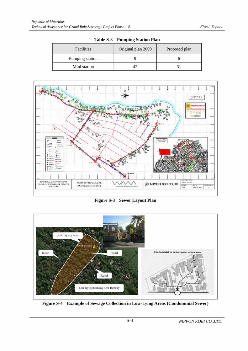
House connection requires drainage pump as for houses in low-lying area, on hollow and at
the backside of hills along beaches. Low cost sewer was proposed such as occupying private
property, condominial sewerage, and grinder pump units for individual and communal
houses.
Topographic survey contributed to the followings:

Republic of Mauritius Technical Assistance for Grand Baie Sewerage Project Phase 1-B
Final Report
S-3 NIPPON KOEI CO.,LTD.
Topographic information (contour map, housing map, etc.)
Sewer layout plan
Number of pumping stations is reduced from nine to six, and proposal of low cost
sewage collection technology
Customer information (household inventory)
Figure S-1 Sewer Main Route Developed by Contour Map
Figure S-2 Sewer Main Route
Republic of Mauritius Technical Assistance for Grand Baie Sewerage Project Phase 1-B
Final Report
S-4 NIPPON KOEI CO.,LTD.
Table S-3 Pumping Station Plan
Facilities Original plan 2009 Proposed plan
Pumping station 9 6
Mini station 42 31
Figure S-3 Sewer Layout Plan
Figure S-4 Example of Sewage Collection in Low-Lying Areas (Condominial Sewer)

Republic of Mauritius Technical Assistance for Grand Baie Sewerage Project Phase 1-B
Final Report
S-5 NIPPON KOEI CO.,LTD.
Table S-4 House Inventory
Household Inventory SurveyTechnical Assitance for Grand Baie Sewerage Project Phase 1-B
Aerialphoto
referenceNo.
Hosuereference
No.Village Address
CWAAC No.
OwnershipName
TelephoneHousing lotelevation oflowest point
Roadelevation
Housing lothigher or lowerthan, or equal
to road
Houseconnection
length
Measuredin-situ
DTM/ aerialphoto
Rejected
Public Private Detected Not Detected GL + m GL + m cm m1 1 Pts aux Cannoniers Navneet Akaloo 269 0929 * * 7.52 7.87 0.35 81 *1 2 Pts aux Cannoniers Soobash Chandra Ramparsad 263 5129 * * 7.18 7.98 0.80 23 *1 3 Pts aux Cannoniers Island View Paula Labat 258 0755 * * 7.00 7.87 0.87 50 *1 4 Pts aux Cannoniers Island View Paula Labat 259 0755 * * 7.95 46 *1 5 Pts aux Cannoniers Jean Bernard Tyack 727 0080 * * 7.52 7.53 0.01 57 *1 6A Pts aux Cannoniers Jean Francois Adam 727 0080 * * 7.29 7.11 0.18 73 *1 6B Pts aux Cannoniers Jean Francois Adam 727 0080 * * 0.00 *1 6C Pts aux Cannoniers Jean Francois Adam 727 0080 * * 0.00 *1 7 Pts aux Cannoniers Frederick Robert * * 7.18 7.11 0.07 80 *1 8 Pts aux Cannoniers Coeur Volant Christine Colin 752 8715 * * 7.51 6.86 0.65 65 *1 9A Pts aux Cannoniers Veronique Moufferon 423 6000 * * 9.66 6.86 2.80 78 *1 9B Pts aux Cannoniers Noel Raffray 423 6000 * * 0.00 *1 9C Pts aux Cannoniers Gilbert Deleplaque 423 6000 * * 0.00 *1 24B Pts aux Cannoniers Serge Bathfield/Meur c/o Sunil 910 5122 * * 0.00 *2 25 Pts aux Cannoniers Bougois * * 9.90 11.81 1.91 31 *2 26 Pts aux Cannoniers Alain Paillusseau 263 3845 * * 10.20 11.67 1.47 27 *2 27 Pts aux Cannoniers 23 Coastal Road Maurice Martin 258 1660 * * 11.42 11.52 0.10 *
2 28 Pts aux Cannoniers 24 Coastal RoadMaurice Martin c/o Mme La
Grue931 5065 * * 12.05 *
2 29 Pts aux Cannoniers Roger Koenig c/o Subash 263 5486/261 3197 * * 10.57 12.31 1.74 56 *2 30 Pts aux Cannoniers Alexis Harel 735 8668 * * 10.61 11.71 1.10 68 *2 31 Pts aux Cannoniers John Tagg (Jessica) 932 3804 * * 9.13 11.71 2.58 69 *
Survey MethodologyHousehold Details
BoundaryFront Road
Housing lot survey items
(2) Geological Survey
Columnar joints in lava rocks such as basalt predominate geologically in the project area
(Figure S-5). Lava rock layer was detected by geological survey and site reconnaissance in
the whole project area. Lava rock layers with vertical and horizontal joints are hard or
weathered.
Geological survey detected lava rocks at five pumping station sites excluding one site.
Ground water level is also detected deep as sea water level since only two sampled water was
obtained.
Lava rocks are jointed, and consists of hard and weathered rocks. Construction work and
quarry use crusher. Sewer main is planned along the main road with gravity flow and
approximately 1 m difference can be excavated. Small roads are difficult to excavate and
drainage pump must be applied. Proposed sewer layout plan displaces adjacent MS
considering cost of construction and operation and maintenance (O&M) of MS. Sewer pipe is
laid in ground water at an elevation of 2 m. Construction works are intended for drainage
pump because of limited ground water inflow through rock joints.

Republic of Mauritius Technical Assistance for Grand Baie Sewerage Project Phase 1-B
Final Report
S-6 NIPPON KOEI CO.,LTD.
Figure S-5 (Left) Columnar Joints Exposed on Beach Side, (Right) Ball-like Porous Basalt
Figure S-6 Summarized Columnar Section
The basalt rocks distributed in the studied area exposed on ground surface or underground up
to 3.0 m. Furthermore, fresh basalt is very hard with N-value of more than 50, and an
allowable bearing capacity of 700~800 kN/m2,which is sufficient for the structure’s
foundation. The proposed pumping station shall be constructed by removing the loose
colluvial surface and building a spread foundation on hard basalt rock.
Sewer construction will be affected by hard lava rocks in the whole project area, and the
on-going project applies excavation machine for executing open-cut method. Sewer depth
shall be decided to compare the cost and maintenance of pumping and open-cut method by

Republic of Mauritius Technical Assistance for Grand Baie Sewerage Project Phase 1-B
Final Report
S-7 NIPPON KOEI CO.,LTD.
gravity flow, which can be applied with less ground water leakage.
Figure S-7 Construction in Residential Area
(Left: Sewer construction in Quatre Bornes, Right: Housing construction in Grand Baie)
(3) Injection Well Survey
The two existing injection wells operates alternately while one injection well has been
abandoned. The study bored additional two injection wells and conducted permeability tests.
Since lava tubes were not detected in Grand Baie Region, injection is performed through
cracking of lava rocks. Distribution of injection wells are determined considering the lava
flow direction in Mont Virer, existing well layout, and candidate sites for future sewerage
system expansion. Figure S-8 shows the location of the injection wells.
The first injection well (BH-4) was suspended at 52 m deep because boring facing cavity
rock layer and debris of 15 cm cannot be exploited. The second well (BH-5) was amended
from 300 mm to 380 mm in diameter.
Pumping tests shown in Figure S-9 detected that transmissivity, measured between 100 and
1,000 mins during the 24 hr pumping tests, in BH-4 and BH-5 are 9,311 m2/day
(1.08x10⁻¹ m2/s) and 15,372 m2/day (1.78x10⁻¹ m2/s), respectively as shown in Table S-5.
Figure S-8 Location of Injection Well Tests

Republic of Mauritius Technical Assistance for Grand Baie Sewerage Project Phase 1-B
Final Report
S-8 NIPPON KOEI CO.,LTD.
Figure S-9 Pumping Test (Tentative)
Table S-5 Pumping Test Result
No. Step Duration of
Test (mins)
Q (Yield)
m3/h
s (Drawdown)
m
s/Q
h/m2
Q/s
m2/h
BH-4
1 30 25.5 0.03 0.00118 850.0
2 30 50.2 0.05 0.00100 1,004.0
3 30 75.6 0.10 0.00132 756.0
4 30 106.0 0.16 0.00151 662.5
BH-5
1 30 69.9 0.03 0.00043 2,330.0
2 30 154.0 0.02 0.00013 7,700.0
3 30 227.7 0.01 0.00004 22,770.0
4 60 363.0 0.09 0.00025 4,033.3
(4) Inflow and Infiltration Mitigation Plan
Inflow rate of the existing Grand Baie sewerage is fluctuating regularly in commercial area
and continuous in residential area. However, irregular flow reaches three to four times of that
in dry weather as shown in Figure S-10.

Republic of Mauritius Technical Assistance for Grand Baie Sewerage Project Phase 1-B
Final Report
S-9 NIPPON KOEI CO.,LTD.
Figure S-10 Daily Wastewater Flow Rate of Pumping Station
I/I mitigation of construction stage in Mauritius applies overall measures such as rubber
sealing and PE prefabricated inspection chamber, excavation by manual, pipe bedding of
sand and gravel, pressure test, and separation of storm water from wastewater drain, as seen
on Figure S-11. The existing sewerage system in Grand Baie may have been conveying
inflow from opened manholes and inspection chambers, particularly for grease traps.
However, the most inflow was detected to be from residential wastewater which amounts to
three to four times of that in dry weather, as seen on Figure S-12.
Therefore, the study proposed a stormwater drainage system that performs infiltration,
retention on school ground, and reuse along with comprehensive application of inflow
mitigation, sewer materials waterproofing, and careful construction. As for the treatment
plant, manual valve diversion chamber will be replaced by an automatic valve to prevent
overload at the final sedimentation tank and avoid activated sludge spillage. Replacement of
SCADA in Phase 1-B and expansion of treatment plant in Phase 2 are key opportunities for
upgrading the inflow mitigation plan (see Table S-5 and Figure S-13).
As for soft measure, the study proposed qualified plumbers which are supposed to be certified
engineer, have registration license as plumber and subject to penalties as necessary in
conjunction with public-private partnership. This is intended to prevent inferior plumbing
works; improve capability in trouble shooting for sewer maintenance; and public relation on
sewerage.
Flow rate (PS1)
0
1,000
2,000
3,000
4,000
0 20 40 60 80 100 120 140 160
Date (Aug.1-Dec.31,2010)
Flow
Rat
e(m
3 /day
)Flow rate(PS10 & PS111)
0
100
200
300
400
500
600
Mon W
ed FriSun Tue Thu Sat
Mon W
ed FriSun Tue Thu Sat
Date (Oct.11, Mon-Nov.7, Sun,2010)
Flow
Rat
e(m
3/da
y)
PS10
PS111

Republic of Mauritius Technical Assistance for Grand Baie Sewerage Project Phase 1-B
Final Report
S-10 NIPPON KOEI CO.,LTD.
Sewer with sand bedding
Pipe with socket & seal ring
Figure S-11 Sewer Construction
Habitual flooding
Inundated house
Opened inspection chamber
Cleansing clogged inspection chamber
Figure. S-12 Inundation and Inflow

Republic of Mauritius Technical Assistance for Grand Baie Sewerage Project Phase 1-B
Final Report
S-11 NIPPON KOEI CO.,LTD.
Table S-5 Overall of Inflow and Infiltration Mitigation
O&M of
facilities
Retaining in sewer
Standby pump operation
Bypassing aeration tank
On-Site
Measures
Building sewer repair Repair of pipe and cover and storm drain separation
Disconnection of abandoned septic tank and soak way
Sanitary sewer repair Repair of pipe and cover and storm drain separation
Disconnection of abandoned sewer
Storm water drainage Drainage, infiltration, reuse, and retention
Off-Site
Measures
Sewer & pumping
station
Expansion of sewer capacity, standby pump operation,
Retention reservoir
Treatment plant Bypassing aeration tank
Sedimentation, coagulation, filtration, etc.
Disinfection
Grand Baie government school
Infiltration facility
Stromwater outfall with sedimentation & infilitration (Pointe aux Piments)
Figure S-13 Infiltration and Retaining of Storm Water
Drainage pipe
Bank for overflow

Republic of Mauritius Technical Assistance for Grand Baie Sewerage Project Phase 1-B
Final Report
S-12 NIPPON KOEI CO.,LTD.
3 Conclusion
The study is a technical assistance aiming to promote a smooth ODA loan project of detailed
design and construction, and to enhance project result through topographic and I/I mitigation
surveys.
The study proposed a main sewer route in accordance with the topographic conditions
considering the number of pumping stations and pumping head. Effective wastewater collection
in low-lying areas and customer information, which is required during operation, are also
proposed. Technical and institutional I/I mitigation plan is provided for sewerage facility
management.
Sewerage service requires not only information of customers and facilities, but public relation,
such as tariff levies and claims, and trouble shooting on pipe clogging and offensive odor.
Information necessary on O&M shall be accumulated on each project stage, and institution is
required on urban development project, illicit discharge control and regulation, and design
guideline.

Republic of Mauritius Technical Assistance for Grand Baie Sewerage Project Phase 1-B
Final Report
S-13 NIPPON KOEI CO.,LTD.
No. of house connection / Expansion of service area P
roje
ct s
tage
Topographic survey & Sewer planning
Detail design
Construction
Operation
Role & job Topographical information Sewer layout plan Prototype household information Project volume of house connection
Role & job Sewer design, drawing & mapping Detail household information Project cost estimation Bidding documents
900 houses 4,400 houses
Role & job Construction program Construction Commissioning & hand over Detail household information Drawing & mapping
Role & job Sewer maintenance Tariff levy Renewal of household information Renewal of sewer mapping Coordination with road occupy activities
Information & Institutional system Customer information Sewer mapping Maintenance information Sewerage ordinance & institution for
House connection approval Development project control Illicit discharge control Pre-treatment of business wastewater Tariff levy & collection Qualified plumber
Figure S-14 Roles and Jobs during Survey, Detailed Design and Construction


Republic of Mauritius Technical Assistance for Grand Baie Sewerage Project Phase 1-B
Final Report
1-1 NIPPON KOEI CO.,LTD.
CHAPTER 1 INTRODUCTION
1.1 Background of The Survey
(1) History and Status of Sewerage System Development in Mauritius
Mauritius has issued NEAP1 on 1988 supported by WB recognizing that environmental
prevention and health and welfare of nations are indispensable to sustainable economic
development.
GOM provided a sewerage master plan accordant to NEAP1 of summarizing financial policy
and operation and management in 20 years supported by AfDB. The Grand Baie Wastewater
Project is defined as one of the priority project components of NSP in 10 years.
Sewerage Development Goal of NEAP1
Served population of 50% on 2014 to 80% on 2030
* Sewerage project has actually delayed 40% at present as for targeted goal of 50% in 2014.
(2) Present Status and Plan of Grand Baie Sewerage Development
The Grand Baie Region, where the sewerage project is implemented, is rich in coral reef and
sugar cane fields, which respectively serve as a tourist destination and produce products for
export, earning overseas money.
GOM has provided a F/S for the Grand Baie Wastewater Project in 1994 supported by AFD
of the French government. At present, the sewerage system of the Grand Baie Wastewater
Treatment Plant, which consists of pumping stations, sewers, and house connection in Grand
Baie Region, were constructed through the Grand Baie Wastewater Project Phase 1-A as
shown in Figure 1.3-1. However, only 10% of the population is served, and house connection
project is urgent since wastewater from residential and commercial buildings are discharged
on ground without any treatment. Discharge of wastewater leads to contamination of coastal
and ground waters. The Grand Baie Sewerage Project aims to develop the sewerage service
area in order to promote house connections and utilize excess treatment capacity. Phase 1-B
costing 8.27 billion yen (Loan Agreement of 7.012 billion yen) was allocated on July 8, 2010,
aimed to develop additional house connection of 4.400 s.

Republic of Mauritius Technical Assistance for Grand Baie Sewerage Project Phase 1-B
Final Report
1-2 NIPPON KOEI CO.,LTD.
Table 1.1-1 Sewerage Project Phase1-A & Phase1-B
(3) Background of the Project
Technical Assistance of Grand Baie Sewerage Project Phase 1-B (hereinafter referred to as
the Study), aims to enhance the project efficiency of Grand Baie Wastewater Project on
environmental conservation and public health improvement through facilitating house
connections and wastewater treatment service in North Grand Baie Region where households
discharge wastewater without treatment.
1.2 Objectives of the Study
The Study supports the technical assistance program for a more efficient Grand Baie
Wastewater Project. The study aims to conduct the following prior to detailed design:
1) Topographic and geological survey in the area of Sewerage Project Phase 1-B (route
survey, individual housing lot survey, and geological survey)
To collect technical information for further study of detailed design
2) Borehole investigation at wastewater effluent injection
To collect technical information for further study of detailed design
3) I/I survey in existing sewerage service area of Phase 1-A
To execute survey and to provide technical transfer through seminars
Phase1-A (Existing) Phase1-B (Plan)
AFD (France) JICA(Japan)219 ha 1,268 ha
(Dec. 2006) 2016
4,600 cap. (2007)5,180 cap. (2030)
22,980 cap. (2007)25,810 cap. (2030)
Treatment plant5,530 m3/day(Retention 2,030 m3/day)
-(Extended in Phase2 )
Injection well 3 wells 2 wells
Pumping station13 Pumping station 6 Mini pump station
9 Pumping station42 Mini pump station
Sewer
35.5 km (168 m/ha) Gravity :PVC Pressure: HDPE( <250 mm) DI(300 mm< )
94 km (79.7 m/ha) Gravity : 79.2 km Pressure: 13.4 km
House connectionHouse hold 1,730 connectionNon-domestic 22 connectionTotal 1,752(Sep. 2009)
4,348 connection
Others SCADA SCADA (replace)
Proj
ect c
ompo
nent
Donor
Projected year(Operation start)
Service Area
Served population
Republic of Mauritius Technical Assistance for Grand Baie Sewerage Project Phase 1-B
Final Report
1-3 NIPPON KOEI CO.,LTD.
Proposal of applying I/I mitigation measures on Phase1-B Project
1.3 Implementing Organization and Survey Area
(1) Implementing Organization
The implementing organizations for this Study are as follows:
1)Ministry of GOM
WRU, Ministry of Energy and Public Utilities,
2)Counterpart
WMA, Wastewater Management Authority
(2) Survey Area
The area of the Survey is Grand Baie Region, which is located north of Mauritius, is shown in
Figure 1.3-1.

Republic of Mauritius Technical Assistance for Grand Baie Sewerage Project Phase 1-B
Final Report
1-4 NIPPON KOEI CO.,LTD.
Figure 1.3-1 Grand Baie Sewerage Project Phase 1-A, Phase 1-B, and Phase 2
1) Phase 1-A : Existing sewerage Area 【 】Brown
2) Phase 1-B : Survey Area 【 】Red
3) Phase 2 : Future Developing Area 【 Blue 】

Republic of Mauritius Technical Assistance for Grand Baie Sewerage Project Phase 1-B
Final Report
1-5 NIPPON KOEI CO.,LTD.
Septic tank,15%
Groundrecharge,
84%
Sewerage, 1%
1.4 Points to be Noted When Implementing the Survey
(1) Characteristics of Grand Baie Region and Points to Develop the Sewerage System
Characteristics of Grand Baie Region and points to develop sewerage system are described as
follows.
1) Typical Geological Condition
Lava rocks appear all over the Project area. Most rocks are buried in shallow earth
classified by 1) shallow sandy layer, 2) rocky layer, and 3) rocks.
2) Careful Layout Plan of Pumping Station
Wastewater collection system applied in the project area consists of gravity and
pressurized flows, which are generally adopted in Mauritius. Sewers are laid with some
gradient. Lift stations and pressurized flow are adopted where there are deep excavations.
The Sewerage Project adopts pumping stations in order to avoid deep excavation.
Furthermore, the location of pumping stations located within private properties should be
decided at the earliest since land acquisitions are necessary.
* Layout plan of pumping stations should be reviewed according to route, topographical
and geographical surveys since the Preparatory Study of Grand Baie Sewerage Project in
Mauritius used 1:2,500 scale maps developed 20 years ago.
3) Low Rate of House Connection
Water closets are available for 93% of households of the Grand Baie Region according to
the 2000 National Census, which was before wastewater service operation started. Since
84% of wastewater is discharged into groundwater, as shown in Figure 1.4-1, sewerage
development and house connection are urgently required.
Figure 1.4-1 Wastewater Treatment
Source: Preparatory Survey for Grand Baie Sewerage Project in Republic of Mauritius

Republic of Mauritius Technical Assistance for Grand Baie Sewerage Project Phase 1-B
Final Report
1-6 NIPPON KOEI CO.,LTD.
4) Indispensable Project Component of House Connection
House connection requires design of sewers in private properties, as the house connection
project is executed by the public sector. Practical design of house connection requires
careful survey of private properties so as not to damage privately owned assets.
5) Huge Amount of Inflow and Infiltration
Wet season flow amounts to 2.2 times of the yearly average of dry-weather flow in spite of
a separate sewer system. I/I mitigation measures are required to prevent inundation of
pumping stations and provide full capacity of the sewerage system.
Sewerage development plan estimates a design I/I of 10% of domestic and commercial
wastewater. Pumping capacity can approve such design I/I, which should reduce the
present 1.2 to 0.1 times of the average dry-weather wastewater flow.
(2) Survey Methodology and Points to Develop Sewerage System
The Study includes collection of information on sewer lines, construction methods, construction
duration, cost estimation, and safety management. The Study also consists of topographic
surveys on route and private housing lot, geographical surveys, and sewer route survey of trunk
sewer, local sewer and house connection. Survey methodology and points for sewer design are
described in Table 1.4-1.
Table 1.4-1 Points of The Study
Study subject Study contents Points to be studied
1) Existing
Drawings (Road
map, topographic
map, Housing lot
map)
To collect road maps, which
describes road width, principal
structures, and houses for sewer
plan. Also, to collect aerial
photo.
Although current land use map is not available, the
water supply sector may provide road and housing lot
map. Such map shall be collected through WMA.
Data on housing boundaries is important since house
connection is implemented by public works. Housing
boundary map of water supply sector shall be
collected. In case housing boundary data is
unavailable, point of sewer house connection will be
decided adjacent to water supply connections.
2) Watershed and
Project Area
condition
Topographic condition and
boundary of watershed,
drainage route, house
distribution, traffic, and
drainage of individual house are
studied.
Housing lot survey includes hollow place at low land
area and ground level elevation in order to decide
drainage route.
Sufficient land acquisition is required for pumping
station.
3) Public Utilities
Survey (Existing
sewer,
Road layout, pavement
material, water supply, electric
power supply,
Present information and future plan on pavement
material and public utilities are collected from relevant
organizations.
Republic of Mauritius Technical Assistance for Grand Baie Sewerage Project Phase 1-B
Final Report
1-7 NIPPON KOEI CO.,LTD.
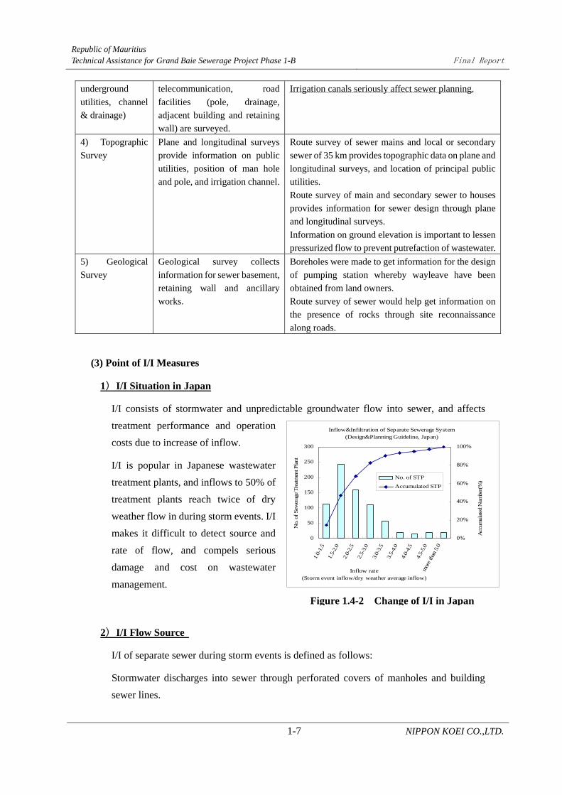
Figure 1.4-2 Change of I/I in Japan
Inflow&Infiltration of Separate Sewerage System(Design&Planning Guideline, Japan)
0
50
100
150
200
250
300
1.0-
1.5
1.5-
2.0
2.0-
2.5
2.5-
3.0
3.0-
3.5
3.5-
4.0
4.0-
4.5
4.5-
5.0
mor
e th
an 5
.0
Inflow rate(Storm event inflow/dry weather average inflow)
No.
of Sew
erag
e Tre
atm
ent P
lant
0%
20%
40%
60%
80%
100%
Acc
umul
ated
Num
ber(
%)
No. of STP
Accumulated STP
underground
utilities, channel
& drainage)
telecommunication, road
facilities (pole, drainage,
adjacent building and retaining
wall) are surveyed.
Irrigation canals seriously affect sewer planning.
4) Topographic
Survey
Plane and longitudinal surveys
provide information on public
utilities, position of man hole
and pole, and irrigation channel.
Route survey of sewer mains and local or secondary
sewer of 35 km provides topographic data on plane and
longitudinal surveys, and location of principal public
utilities.
Route survey of main and secondary sewer to houses
provides information for sewer design through plane
and longitudinal surveys.
Information on ground elevation is important to lessen
pressurized flow to prevent putrefaction of wastewater.
5) Geological
Survey
Geological survey collects
information for sewer basement,
retaining wall and ancillary
works.
Boreholes were made to get information for the design
of pumping station whereby wayleave have been
obtained from land owners.
Route survey of sewer would help get information on
the presence of rocks through site reconnaissance
along roads.
(3) Point of I/I Measures
1)I/I Situation in Japan
I/I consists of stormwater and unpredictable groundwater flow into sewer, and affects
treatment performance and operation
costs due to increase of inflow.
I/I is popular in Japanese wastewater
treatment plants, and inflows to 50% of
treatment plants reach twice of dry
weather flow in during storm events. I/I
makes it difficult to detect source and
rate of flow, and compels serious
damage and cost on wastewater
management.
2)I/I Flow Source
I/I of separate sewer during storm events is defined as follows:
Stormwater discharges into sewer through perforated covers of manholes and building
sewer lines.

Republic of Mauritius Technical Assistance for Grand Baie Sewerage Project Phase 1-B
Final Report
1-8 NIPPON KOEI CO.,LTD.
誤接合による浸入 Down spout
cross connection
Open IC cover inflow
Ground-water infiltration of foul fitting, connection and failure
Inspection chamber
Wastewater
Building sewer(Private)Public sewer
Ground-water infiltration of foul fitting, connection and failure
IC odor release hole inflow
Open cover inflow
Storm water drain
House connection
Ground-water infiltration of foul fitting, connection and failure Ground water infiltration of MH block fitting
MH odor release hole inflow
Open MH cover inflow
Inspection chamber
Stormwater also infiltrates through pipes and damaged pipes of sewer when it fills
back-filled trenches.
Figure 1.4-3 I/I of Separate Sewer
Surveyed I/I flowrate after stepwise rehabilitation in Japan is reported in Table 1.4-2,
which shows I/I of whole facilities of sewer collection system..
Table 1.4-2 Stepwise I/I Rehabilitation
I/I Source Flow Rate
House Connection and Inspection Chamber (Public) 40 %
Building Sewer (Private) 24 %
Public Sewer (Public) 36%
Source: Kobe City, Japan

Republic of Mauritius Technical Assistance for Grand Baie Sewerage Project Phase 1-B
Final Report
1-9 NIPPON KOEI CO.,LTD.
3)Points of I/I Measures
I/I measures should be applied comprehensively such as 1) training of plumbers; 2) careful
construction and maintenance of sewers; and 3) construction of stormwater drainage
system to reduce I/I flow.
However, rehabilitation of private and public sewers can be difficult as these involve
higher cost and longer construction period. When I/I issues appear, survey should detect
such data on flowrate, water quality and dilution rate, and I/I event frequency. The most
rational measure should be applied considering not only capacity of sewer, pump and
treatment but also O&M matters and cost-benefit analyses.


Republic of Mauritius Technical Assistance for Grand Baie Sewerage Project Phase 1-B
Final Report
2-1 NIPPON KOEI CO.,LTD.
CHAPTER 2 STUDY METHODOLOGY
2.1 Study Schedule
Field survey started on December 16, 2010 after the submission of the Draft Inception
Report. Result discussed with WMA was reviewed to field survey planning and TOR of the
Study contract.
The Draft Final Report was submitted on March 11, 2011 to JICA Madagascar Office. And
the conclusion of the Study was reported on March 15, 2011 to the Embassy of Japan.
During field survey, progress was reported to JICA Madagascar Office and WMA on
February 11, 2011. The Study Team then reported to JICA Headquarters on March 28, 2011
and concluded the Final Report.
Table2.1-1 summarizes the schedule of the Study.
Table 2.1-1 Study Itinerary
Year/Date Organization Subject
2010
Dec
9 Thu. JICA Contract
Inception Report (Draft) submission
15 Wed. Study Team Study Team Departure
16 Thu. Study Team Study Team Arrival in Mauritius
17 Fri. WMA Preliminary Meeting
18 Sat. Study Team Project Site Visit
19 Sun. Study Team Project Site Visit
20 Mon. WMA Kick-off Meeting and Inception Report (Draft)
submission
22 Wed.. Luxconsult Co. Ltd. Meeting on TOR of Employment Contract
27 Mon. Luxconsult Co. Ltd. Employment Contract
28 Tue. WMA TOR on Topographic Survey
Study Team Starting Street Survey
2011
Jan.
7 Fri. WMA Final Inception Report Submission
Report on Study
12 Wed. WRU/WMA Water Resource Unit Meeting on Core Hole &
Borehole Test
13 Thu. Mauritius University Consultation with Dr. Andre Chan Chin on Borehole
Test
14 Fri. WMA Sewer Main Route & Pumping Station Layout
17 Mon. Study Team Selection of 900 Low-Lying Houses
18 Tue. WMA Field Meeting on Core Hole Survey
19 Wed. WMA Field Meeting on Borehole Survey

Republic of Mauritius Technical Assistance for Grand Baie Sewerage Project Phase 1-B
Final Report
2-2 NIPPON KOEI CO.,LTD.
20 Thu. Study Team Team Member Nishikawa left for Japan
21 Fri. WMA Sewer Main Route & Pumping Station Layout
Study Team Awarding on Core Hole and Bore Hole Contract
22 Sat. Study Team Nippon Koei Staff Kawahara Arrival
25 Tue. Water Research Co. Meeting on TOR
WMA Report on Core Hole &Bore Hole Contract
27 Thu. WMA
Water Research Co.
Field Meeting on Bore Hole Survey
28 Fri. WRU/WMA Water Resource Unit Meeting on Core Hole & Bore
Hole Test
31 Mon. WMA Meeting on Study
Feb. 2 Wed. WMA Arrangement on Land Approval
4 Thu. WMA Acceptance of Land Approval of Core Hole Test
7 Mon. WMA Meeting on Study Progress
10 Thu. Study Team Started Core Hole Drilling Field Work
11 Fri. JICA/WMA JICA Madagascar Office Meeting
14 Mon. WMA/WRU
Mont Choisy Ltd. Co.
Meeting on Land Approval for Bore Hole
15 Tue. WMA/ Mont Choisy
Ltd. Co.
Borehole Site Meeting
17 Thu. RDA/WMA Site Meeting on Sewer Plan in Classified Road with
RDA
18 Fri. WMA Meeting Study Progress
22 Tue. Water Research Co. Starting Borehole Drilling Field Work
25 Fri. WMA Meeting Study Progress
Water Research Co. Amendment Meeting on Borehole Contract
Mar. 4 Fri. WMA Meeting Study Progress
11 Fri. WMA Draft Final Report Submission
14 Tue. JICA Office Report on Study
15 Wed. Japan Embassy Report on Study
17
18
Thu.
Fri. Study Team
Departure from Mauritius
Arrival in Narita
23 Wed. JICA HQ Draft Final Report Submission
28 Mon. JICA HQ Final Report Submission
2.2 Staffing
The Study collects information on topography, sewer route, geology and underground
facilities prior to detailed design for smooth implementation of the Phase1-B Project. The
surveys consist of topographic surveys in Phase1-B and wastewater effluent injection wells.
I/I survey in Phase1-A area also applies to I/I mitigation measures of Phase1-B.

Republic of Mauritius Technical Assistance for Grand Baie Sewerage Project Phase 1-B
Final Report
2-3 NIPPON KOEI CO.,LTD.
The Study had several issues such as the broad area and individual housing lot survey in
restricted terms. In the organization of team members, the following were considered:
i. Experts with sufficient experience on sewer route planning, topographical survey,
and I/I mitigation.
ii. Experts familiar with Japanese ODA projects and can execute surveys effectively.
iii. Experts with sufficient communication skills with government organizations and
contractors in Mauritius, and can utilize information and data in English.
iv. Topographic, geological and injection well surveys are contracted to private
companies who haveexperiences in Mauritius.
Team members are experts on the following fields:
Team Leader/Sewer Design Expert: Yakuro Inoue
Sewer Survey Expert: Takamasa Nishikawa
Geological survey expert: Naoki Kawahara*
* Additional Team Member necessary because there are a lot of unexpected works
such as getting permission and application procedures on geological and injection well
surveys.
Table 2.2-1 shows the assignment schedule of the experts.
Table 2.2-1 Assignment Schedule
2010
計
Mauritius Japan
Team Leader/Sewerage Design Yakuro INOUE Nippon Koei 2 17 31 28 18 3.13
Sewer Survey Takamasa NISHIKAWA Nippon Koei 3 17 21 20 18 2.53
Geological survey Naoki KAWAHARA Nippon Koei 11 12 0.77
Sub-Total 6.43
Team Leader/Sewerage Design Yakuro INOUE Nippon Koei 2 6 7 0.43
Sewer Survey Takamasa NISHIKAWA Nippon Koei 3 2 2 2 0.20
Geological survey Naoki KAWAHARA Nippon Koei
Sub-Total 0.63
Work in Mauritius 6.43 0.63
Work in JapanTotal
7.06
Wor
k in
Mau
ritiu
sW
ork
in J
apan
Report Submission
Position Name Company Rank
MM
12 1 2 3 4
ICR
Preparation of IC/R
Work in Mauritius
F/R
Preparation of DF/R
DF/R
Preparation of F/R


Republic of Mauritius Technical Assistance for Grand Baie Sewerage Project Phase 1-B
Final Report
3-1 NIPPON KOEI CO.,LTD.
CHAPTER 3 TOPOGRAPHIC SURVEY
3.1 Street Survey
3.1.1 Methodology of Street Survey (Center Line and Longitudinal Profile)
(1) Essential Requirements
Route survey provides topographic maps for detailed design.
The sewer design expert decided to place sewer lines where route survey has identified
street center, longitudinal profile, underground utilities (water supply, telecommunication,
etc.), street gutters, and intersections.
Topographic maps are processed into CAD data (1:3000 scale maps is consulted with
C/P).
Survey
area
Point aux Canonniers, Petit Raffray, The Vale, Pereybere and Cap Malheureux, and
Sottise
(Approx. 35 km of existing streets)
Survey
items
Plane survey:35 km×20 m, Centerline:50 m interval, Longitudinal Profile:35 km、
TBM:500 m interval
(2) Survey Methodology
The survey is executed using electro-optical distance meter and GPS. The electro-optical
distance meter detects phase of waves and transfers them to distance. GPS of digital
terrain model (DTM) detects location and elevation of subjects using GPS satellite waves.
Street surveys between villages are executed through GPS to shorten the survey period.
The electro-optical distance meter was used for street surveys in villages since GPS
cannot be applied due to the presence of big trees.
Total Station
Total station consists of a transit and electro-optical distance meter, and it surveys gradient
and distance simultaneously. Surveyed results are digitized on monitor and recorded.
Location and elevation of objects are processed in three-dimension.

Republic of Mauritius Technical Assistance for Grand Baie Sewerage Project Phase 1-B
Final Report
3-2 NIPPON KOEI CO.,LTD.
Street Survey (GPS):
*GPS Antenna Receiver
Street Survey (GPS): *GPS
Rover in RTK Mode
Street Survey (Total Station)
Figure 3.1-1 Survey Situation

Republic of Mauritius Technical Assistance for Grand Baie Sewerage Project Phase 1-B
Final Report
3-3 NIPPON KOEI CO.,LTD.
3.1.2 Result of Street Survey
(1) Street Survey Route
Street route survey was decided considering the main sewer network plan as shown in
Section 3.3. The length of street survey is about 40 km and the route is shown in Figure
3.1-2.
Figure 3.1-2 Street Survey Route
The Study Team set the route number (Route-1 to Route-24) and reference node number
(R1-1 to R14-2) to specify the location easily in 2D diagram and longitudinal profiles.
(2) Result of Street Survey
The result of street survey is shown in 2D diagram (1:3000 scale) and longitudinal
profile (1:100 vertical scale, 1:1000 horizontal scale). These drawings are attached in the
report Volume 2, Report on Topographic Survey.

Republic of Mauritius Technical Assistance for Grand Baie Sewerage Project Phase 1-B
Final Report
3-4 NIPPON KOEI CO.,LTD.
3.1.3 Application of Surveyed Result
Street survey result is developed into contour maps showing the topographical condition of
high and low areas. The direction of the sewer flows and necessity of pumping station were
decided by the contour maps as seen in Figure.3.1-3, right.
As for sewer main route, contour maps have provided an alternative sewer main route which
bypasses high land and removes two pumping stations, including a 25 m head loss. Site
reconnaissance confirmed sewer flow direction and details of alternate pipe route as seen in
Figure 3.1-3, left.
Figure 3.1-3 Low-Lying Area and Sewer Main Alternative in Petit Raffray
PS
PS
PS
Original plan
Proposed plan

Republic of Mauritius Technical Assistance for Grand Baie Sewerage Project Phase 1-B
Final Report
3-5 NIPPON KOEI CO.,LTD.
Occupying farm land for sewer main, where public roads are located higher than private farm
lands, reduces sewer length and MS.
Figure 3.1-4 Sewer Main Occupying Private Property (Farm land) in The Vale
Private land occupation (MS replaced to gravity sewer)
Original plan
Proposed plan
PS8
P

Republic of Mauritius Technical Assistance for Grand Baie Sewerage Project Phase 1-B
Final Report
3-6 NIPPON KOEI CO.,LTD.
3.2 Housing Lot Survey
3.2.1 Methodology of Housing Lot Survey
(1) Essential Requirements
Plan survey is intended for Phase1-B area excluding Mont Choisy East Development
Project, with approximately 4,400 households, and route between individual household
and trunk sewers.
Proposed house connections were processed into CAD file.
Survey
area
Point aux Canonniers, Petit Raffray, The Vale, Pereybere and Cap Malheureux,
and Sottise
(Approx. 4,400 households)
Survey
items
Street: Plane survey:5 km×20 m; TBM:500 m interval; Longitudinal profile:
50 m interval
Housing lot: Plane survey:
900 households > Location of wastewater drainage facilities, lowest ground
elevation & drain direction
3,500 households> Check household lot higher than street, aerial photo
detection of sewer line
Table 3.2-1 Housing Lot Survey Scope
Object Amount Scope
Low-Lying Area
Housing Lot
1,112 houses
(900 planned)
810 at ground
level surveyed
・Location of wastewater discharge facilities
・Obstacles of house connection
・Building lay-out
・Elevation
Others 5,626 houses
Sewer route determined by aerial photo (check
elevation of house connection)
* Detail design executes housing lot survey
Total 6,738 houses (4,400 houses planned)
(2) Survey Methodology
1)Selection of Low-Lying Area Housing Lot (Target of Housing Lot Survey)
Housing land development in the survey area has been progressing rapidly in the
recent years. Therefore, there is no permanent road map available for the sewer
network plan. At present, the Ministry of Housing and Lands is digitizing road maps

Republic of Mauritius Technical Assistance for Grand Baie Sewerage Project Phase 1-B
Final Report
3-7 NIPPON KOEI CO.,LTD.
with the aid from Australia.
In this Study, the Study Team use aerial photos published by the Ministry of Housing
and Lands to detect the housing lot and make sewer network plan. The number of
housing lots in the study area, determined by aerial photo, was 6738.
The Study Team picked out low-lying area housing lots enough to make the sewer
network plan by the field survey. The number of lots found was 1,112.
The location and shape of the specified households were digitized through CAD from
aerial photos and GIS survey results. These information were utilized for the
arrangement of results of the housing lot survey and planning of house connection.
2)Request for Cooperation for Survey
Since entering properties is a matter of privacy, the government administration was
vital for the execution of this Study. Therefore, WMA issued request letters to the media,
particularly to radio stations, and regional councils in advance. WMA staff informed
each household with communiqué. Site reconnaissance detected 1,112 houses in
low-lying area.
Figure 3.2-1 Request for Cooperation (Communiqué)

Republic of Mauritius Technical Assistance for Grand Baie Sewerage Project Phase 1-B
Final Report
3-8 NIPPON KOEI CO.,LTD.
Figure 3.2-2 Household Interview (WMA Staff)
3)Housing Lot Survey
WMA staff and JICA Study Team visited together each 1,112 households to carry out
surveys. JICA Study Team used individual housing lot survey form, as seen in Figure
3.2-3, to perform surveys and get as much information as possible, as shown in Table
3.2-2. In addition, the study area involves resorts and a lot of holiday cottages for rent.
Therefore, owners and residents are not the same in many cases, and JICA Study
Team could not get enough information in that case even with the assistance of
WMA staff. In case the residents would not permit to go inside their properties, JICA
Study Team will supplement the necessary information based from oral interviews.

Republic of Mauritius Technical Assistance for Grand Baie Sewerage Project Phase 1-B
Final Report
3-9 NIPPON KOEI CO.,LTD.
Table 3.2-2 Information Collected from the Housing Lot Survey
Collected Information Information Receiver Purpose of the Information Acquisition
Address WMA Basic customer information
Owner WMA Basic customer information
Phone Number WMA Basic customer information
CWA Account Number WMA Basic customer information
(For fare collection)
Front Road Proprietary JICA Study Team Basic information for detail design
(To check the necessity of wayleave)
Location of Wastewater
Discharge Facilities
JICA Study Team Basic information for detail design
(To decide the location of house connection)
Location of Other Utility
Service Line
JICA Study Team Basic information for detail design
(To decide the location of house connection)
Length of House
Connection
JICA Study Team Basic information for detail design
(To calculate the amount of construction works)
Elevation of Front Road JICA Study Team
(GPS Survey)
Basic information for detail design
(To decide the pipe depth)
Lowest Elevation in
Housing Lot
JICA Study Team
(GPS Survey)
Basic information for detail design
(To decide the pipe depth)

Republic of Mauritius Technical Assistance for Grand Baie Sewerage Project Phase 1-B
Final Report
3-10 NIPPON KOEI CO.,LTD.
Individual House Lot Survey Form
No/ Map No. / Aerial Photo No.
Survey date
Address
Owner
TEL CWA Account
Front Road □ Public road □ Private
Survey items
1) Boundary of housing lot
□ measured in-situ □ DTM/aerial photo □ not detected
2) Location of wastewater discharge facilities (kitchen, bath, toilet and Laundry)
□ kitchen □ bath □ laundry □ toilet □ septic tank/pit latrine
3) Location of other utility service lines
□ water □ electricity □ telephone line □ others( )
4) Lowest elevation of ground level (household site)
□ measured in-situ □ DTM
+ m
5) Elevation of road level + m
6) Length of house connection
□ measured in-situ □ Aerial photo
Approx. m
7) Combined or separated of building sewer of wastewater sewer and storm water sewer
□ No drainage □ Combined □ Separated
Direction
【Legend】□K:Kitchen, □B:Bath, □T :Toilet, □L :Laundry, □S :Septic tank, □P :Pit latrine
Remarks
Wastewater Management Authority, Gov. of Mauritius
JICA Study Team of Grand Baie Wastewater Project
Address:
Tel:
RO
AD
6) Length of House Connection Approx. m
Building
4) Lowest GL of Household Site + m
5) GL of Road + m
Figure 3.2-3 Individual Housing Lot Survey Form

Republic of Mauritius Technical Assistance for Grand Baie Sewerage Project Phase 1-B
Final Report
3-11 NIPPON KOEI CO.,LTD.
3.2.2 Result of Housing Survey
(1) Housing Map
Figure 3.2-4 shows an aerial photo of house location and building layout, where low-lying
houses are highlighted in pink.
Figure 3.2-4 Housing Map in Point aux Canonniers
(2) Supplementary Street Survey
Accuracy of location and ground elevation for GPS is adjusted through combined street
survey and aerial photo. Street survey is for 35 km (40 km including housing lot survey),
which is equivalent to 40% of the total sewer length. Distributed housing lot surveys
supplemented street survey and collected the overall topographic profile in the project
area.
Low-lying housing: □ colored

Republic of Mauritius Technical Assistance for Grand Baie Sewerage Project Phase 1-B
Final Report
3-12 NIPPON KOEI CO.,LTD.
3.2.3 Application of Surveyed Result
The Study Team selected 1,112 houses in low-lying areas and acquired 810 housing lot
information. Survey results are applied to the local sewer layout plan. The average length of
house connections is 46.9 m. Topographic profile provides a background on the direction of
sewer flow and necessity of pump stations. Household information is also useful for
customer information during the operation stage. Therefore, a prototype of house inventory
is provided, as shown in Table3.2-3.
Since information of housing lot and households is vital for detailed design, construction, and
operation stage, survey on the remaining household information will be continued by WMA.
Table 3.2-3 Prototype of House Inventory (1/2)
Summary of housing lot survey
No. ofTotal House
No. of lowlying house
AddressCWA
AC No.Ownership
NameOwnership
NameTelephone Boundary
Housing lotelevation
House lower thanroad (average)
House connectionlength (average)
Public Private Not Detected house m mPointe aux Cannonries 1,168 174 43 1 102 79 92 106 0 106 130 1.7 55.7
Pereybere & Cap Malheureux 2,864 623 317 152 329 322 307 296 44 207 409 0.8 48.2Petit Raffray 1,738 225 100 97 105 122 96 93 11 92 201 1.2 44.5
The Vale 810 67 38 37 42 27 40 32 9 28 55 0.9 38.2
Sottise 158 23 22 10 22 6 17 18 0 0 15 0.2 32.1Total 6,738 1,112 520 297 600 556 552 545 64 433 810 1.1 46.9
Remarks(1) No. of total house is counted by aerial photo as one house of cottage type buildings.(2) Low lying houses are selected by reconnaisance survey and indicated on map.(3) Figures of Address, CWA AC No., Ownership Name and Telephone are obtained by interviewing.(4) Ground elevation is surveyed on 810 housing lots.(5) Closed house and rejected house are detected by GPS and eye view survey.(6) Remaining household details are contnuously surveyed by WMA.
Household Details
Front Road
Housing lot survey items
Village

Republic of Mauritius Technical Assistance for Grand Baie Sewerage Project Phase 1-B
Final Report
3-13 NIPPON KOEI CO.,LTD.
Tab
le 3
.2-3
Pro
toty
pe
of H
ouse
In
ven
tory
(2/
2)
House
hold
Inven
tory S
urvey
Techn
ical A
ssitan
ce for
Grand
Baie S
ewera
ge Pro
ject P
hase 1
-B
Aeria
lph
otoref
erenc
eNo
.
Hosu
eref
erenc
eNo
.Vil
lage
Addre
ssCW
AAC
No.
Owne
rship
Name
Telep
hone
Hous
ing lo
tele
vatio
n of
lowes
t poin
t
Road
eleva
tion
Hous
ing lo
thig
her o
r lowe
rtha
n, or
equa
lto
road
Hous
eco
nnec
tion
length
Mea
sured
in-sit
uDT
M/ a
erial
photo
Rejec
ted
Publi
cPr
ivate
Detec
tedNo
t Dete
cted
GL +
m
GL +
m
cmm
11
Pts au
x Cann
onier
sNa
vneet
Akalo
o26
9 092
9*
*7.5
27.8
70.3
581
*1
2Pts
aux C
annon
iers
Soob
ash Ch
andra
Ramp
arsad
263 5
129
**
7.18
7.98
0.80
23*
13
Pts au
x Cann
onier
sIsl
and Vi
ewPa
ula La
bat25
8 075
5*
*7.0
07.8
70.8
750
*1
4Pts
aux C
annon
iers
Island
View
Paula
Labat
259 0
755
**
7.95
46*
15
Pts au
x Cann
onier
sJea
n Bern
ard Ty
ack72
7 008
0*
*7.5
27.5
30.0
157
*1
6APts
aux C
annon
iers
Jean F
ranco
is Adam
727 0
080
**
7.29
7.11
0.18
73*
16B
Pts au
x Cann
onier
sJea
n Fran
cois A
dam72
7 008
0*
*0.0
0*
16C
Pts au
x Cann
onier
sJea
n Fran
cois A
dam72
7 008
0*
*0.0
0*
17
Pts au
x Cann
onier
sFre
derick
Rober
t *
*7.1
87.1
10.0
780
*1
8Pts
aux C
annon
iers
Coeur
Volan
tCh
ristin
e Colin
752 8
715
**
7.51
6.86
0.65
65*
19A
Pts au
x Cann
onier
sVe
roniqu
e Mou
fferon
423 6
000
**
9.66
6.86
2.80
78*
19B
Pts au
x Cann
onier
sNo
el Raff
ray42
3 600
0*
*0.0
0*
19C
Pts au
x Cann
onier
sGil
bert D
elepla
que
423 6
000
**
0.00
*1
24BPts
aux C
annon
iers
Serge
Bathf
ield/M
eur c/
o Sun
il91
0 512
2*
*0.0
0*
225
Pts au
x Cann
onier
sBo
ugois
**
9.90
11.81
1.91
31*
226
Pts au
x Cann
onier
sAla
in Pa
illusse
au26
3 384
5*
*10.
2011.
671.4
727
*2
27Pts
aux C
annon
iers
23 Co
astal R
oadMa
urice
Martin
25
8 166
0*
*11.
4211.
520.1
0*
228
Pts au
x Cann
onier
s24
Coast
al Road
Mauri
ce Ma
rtin c/
o Mme
LaGr
ue93
1 506
5*
*12.
05*
229
Pts au
x Cann
onier
sRo
ger Ko
enig c
/o Su
bash
263 5
486/2
61 31
97*
*10.
5712.
311.7
456
*2
30Pts
aux C
annon
iers
Alexis
Harel
735 8
668
**
10.61
11.71
1.10
68*
231
Pts au
x Cann
onier
sJoh
n Tagg
(Jess
ica)
932 3
804
**
9.13
11.71
2.58
69*
Surve
y Meth
odolo
gyHo
useh
old D
etails
Boun
dary
Fron
t Roa
d
Hous
ing lo
t surv
ey ite
ms

Republic of Mauritius Technical Assistance for Grand Baie Sewerage Project Phase 1-B
Final Report
3-14 NIPPON KOEI CO.,LTD.
Main Gravity Sewer
Branch Gravity Sewer
Main Pressure Sewer
Branch Pressure Sewer
Pump Station
Mini Station
WWTP treatment Plant
WWTP
PS-1
PS-2
PS
PS
PS
PS
PS
PS
PS
PS
PS
MS
MS
MS
MS
MS
MSMS
MS
MS
MS
MSMS
MSMS
MS
MS
MSMS
MS
MSMS
MS
MSMS
MS
MS
MS
MS
MS
MS
MS
MS
MS
MS
MS
MSMS
MS
MS
MSMS
MS
Legend
PSMS
1 km
〇250425m
10m
137m
328m
410m
1420m
260m
400m
690m
1255m
70m
351m
298m 904m
1150m170m
120m
380m
160m
600m
755m
560m205m
〇315
φ160
〇315
〇400
φ250
〇500
φ250
〇500〇500
〇500
φ300
〇500
φ300
〇400〇315
〇315
φ200
〇315
φ200
〇315
〇250φ160
Existing 〇500
φ2001360m
10m〇315
505m〇250
110m〇315
〇31540m
3.3 Sewer Main Route Survey
3.3.1 Issues on the Original Plan
Grand Baie Region is situated on a plain with moderate hills where eruptions and lava flows
have created debris. Grand Baie Sewerage Project Phase 1-B plans to develop a sewerage
system in five sewerage service areas: Pointe Aux Cannoniers, Pereybere and Cap
Malheureux, Petit Raffray, The Vale, and Sottise.
Ground level declines gradually in Petit Raffray and The Vale from south to north and west
as shown in the contour map of Figure3.3-2. Pereybere and Cap Malheureux are located
above lava rocks along the beach. Scattered low-lying areas where storm water accumulates
are called swamp.
The original main sewer route consists of two major sewer routes as shown in Figure 3.3-1.
The first sewer route joins the existing Pump Station No. 1 (PS-1) and Petit Raffray through
The Vale and Sottise. The second sewer route runs along Motorway B-45 and the coastal
road in Pereybere and Cap Malheureux.
Source: Preparatory Survey for Grand Baie Sewerage Project in Republic of Mauritius
Figure 3.3-1 Original Main Sewer Route Plan
PS-1
PS-2
PS-3
PS-4
PS-5PS-6
PS-7PS-8
PS-9

Republic of Mauritius Technical Assistance for Grand Baie Sewerage Project Phase 1-B
Final Report
3-15 NIPPON KOEI CO.,LTD.
Issues on the original plan are as follows;
A) The proposed nine relay pumping stations are considered extensive.
B) Pumping stations are planned on private properties, which require land acquisition.
C) A high pumping head of 25 m above ground elevation difference is required. Wastewater
in Petit Raffray is collected in lowest point and pumped up to cross a hill.

Republic of Mauritius Technical Assistance for Grand Baie Sewerage Project Phase 1-B
Final Report
3-16 NIPPON KOEI CO.,LTD.
Figure 3.3-2 Contour Map(1/2)

Republic of Mauritius Technical Assistance for Grand Baie Sewerage Project Phase 1-B
Final Report
3-17 NIPPON KOEI CO.,LTD.
Figure 3.3-2 Contour Map (2/2)

Republic of Mauritius Technical Assistance for Grand Baie Sewerage Project Phase 1-B
Final Report
3-18 NIPPON KOEI CO.,LTD.
3.3.2 Alternative Plan
The street and housing lot surveys have provided detailed contour maps for ground elevation.
The longitudinal survey resulted to an alternative plan of joining Petit Raffray with
Pereybere and Cap Malheureux, where ground elevation is lower. As a result, the alternative
plan has changed the high pumping head requirement of 25 m into an ordinary state,
disregarding two pumping stations, PS-6 and PS-7. PS-7 is replaced by a mini pumping
station due to a decrease in flow rate, serving only the east of The Vale Region.
PS-3, which is approximately 500 m from PS-2, transfers wastewater beyond PS-2. PS-2 is
replaced to a mini pumping station which collects and lifts only the adjacent wastewater.
However, two conveyance pipes are installed.
PS-4 and PS-5 are planned on public property of an existing wastewater treatment plant and
football field, respectively. The number of pumping stations is decreased from nine to six,
and land acquisition will cover two private properties and two sugar cane farms. Amended
pumping location plan avoids delay of project schedule and complicated procedures
attributed to land acquisition.
Figure 3.3-3 shows the comparison of the original and proposed plan, while Table 3.3-1
shows the principal advantages of alternative plan.
Wastewater in Flamonds Road area has been reduced from three to one PS due to relocation
of the releasing point of the mini pumping station into Motorway B-45. As a result, the
housing development area adjacent to the mini pumping station can be served.
Eleven mini pumping stations are planned in the Pointe Aux Cannoires sewerage area. MS-1,
which is close to MS-2, can be integrated since the reverse 1 m gradient has been altered to
gravity flow and MS-2 has been relocated to the main sewer connection.
Table 3.3-1 Advantages of the Proposed Plan
1 Petit Raffray connects to Pereybere & Cap Malheureux in order to avoid 25 m pump head loss.
PS-5 relocated to football field from private lot.
2 PS-7 is replaced to MS due to wastewater in Petit Raffray transferred to Pereybere and Cap Malheureux.
3 PS-2 is replaced to MS as it is near PS 3, which transports wastewater downstream of PS-2.
4 MS in Flamonds Rd transports wastewater to down-stream of PS-1 in order to avoid 3 times pumping. Along with, MS collects new developing housing area on the gravity sewer line.
5 MS collects new developing housing area between existing sewerage area and Phase 1-B area.

Republic of Mauritius Technical Assistance for Grand Baie Sewerage Project Phase 1-B
Final Report
3-19 NIPPON KOEI CO.,LTD.
Original Plan, JICA 2009
Proposed Plan (Final)
Figure 3.3-3 Alternative Study on Pereybere and Cap Malheureux,
Petit Raffray, The Vale and Sottise
Pereybere & Cap Malheureux
Petit Raffray
The Vale
Sottise
PS2
PS4
PS1
PS3
PS5
PS8
PS9
1
23
4
Pereybere & Cap Malheureux
Petit Raffray
The Vale
Sottise GL±25m
5
4

Republic of Mauritius Technical Assistance for Grand Baie Sewerage Project Phase 1-B
Final Report
3-20 NIPPON KOEI CO.,LTD.
3.3.3 The Requirement of Road Development Authority
RDA manages classified roads as shown in Figure 3.3-4. Other public roads are managed by
District Council Office.
Figure 3.3-4 Classified Road of Road Development Authority
RDA requires road occupation approval at detailed design stage. RDA also requires
sufficient sewer depth and concrete work for road crossing and sheath pipe for future urban
development project. Longitudinal road occupation principally provides sidewalks and road
reserves area because of cost and workability of construction and traffic safety issues due to
open manholes. RDA regulates 1.5 m road reserve and 4.5m building setback. Actual roads
do not always have a reserve of 1.5 m. At detailed design stage, careful study and
consultation are required since CWA and telecommunication occupy road sides.

Republic of Mauritius Technical Assistance for Grand Baie Sewerage Project Phase 1-B
Final Report
3-21 NIPPON KOEI CO.,LTD.
3.3.4 Conclusion
(1) Rational Main Sewer Planning as Multi-pump Conveyance Sewer
Since Grand Baie Region is situated on a flat plain with moderate hills, the sewer main is
8 km long with multiple pumps. Urban development projects such as commercial and
housing projects are ongoing along the main road, therefore, urbanization will progress.
The Study proposes a single pump conveyance sewer for easy valve maintenance.
However, multi-pump conveyance sewer is rational for future expansion in order to
collect wastewater adjacent to sewer main route.
Figure 3.3-5 Multi-Pump Conveyance Sewer
(2) Wastewater Putrefaction and H2S Measures
Wastewater easily releases H2S since deposited wastewater putrefies. Since wastewater in
pressurized conveyance is conveyed intermittently and deposits in sewer, H2S corrosion
may occur. Concrete and metallic materials in the receiving tank and screen of Grand Baie
WWTP may corrode. Concrete on receiving tank wall above water level corrodes.
Machinery and concrete of pumping station do not corrode because of ventilation,
deodorization, and short pressure conveyance. Since the pressure mains in Phase 1-B and
Phase 2 projects are long, H2S corrosion may progress. Air injection and concrete
corrosion measures are effective in lengthening durability and reducing maintenance
costs.
WWTP P
P
P

Republic of Mauritius Technical Assistance for Grand Baie Sewerage Project Phase 1-B
Final Report
3-22 NIPPON KOEI CO.,LTD.
WWTP Screen
(Machinery corrosion)
WWTP Receiving Tank
(Concrete corrosion)
Relay Pumping Station
(Fresh machinery & concrete)
Deodorizer
(Activated carbon)
Figure 3.3-6 H2S Corrosion
3.4 Local Sewer Plan
3.4.1 Sewerage Planning Area
Sewerage area is appropriate for densely populated areas and commercial centers. Existing
residential and commercial areas are developed in Grand Baie region. However, balconies
for tourists are built and some are isolated from populated area.
Public awareness obtained from interviews during housing lot survey suggests the
following:
According to a male respondent, residents near swamp recognizes sewerage as
important infrastructure because groundwater lever rises and wastewater retains during
rainy season.
According to a female respondent, septic tank has not been desludged since stormwater
and wastewater easily infiltrate ground.

Republic of Mauritius Technical Assistance for Grand Baie Sewerage Project Phase 1-B
Final Report
3-23 NIPPON KOEI CO.,LTD.
From another a female respondent, septic tank releases offensive odor, and sewerage
service relieved septic cleansing.
From another a female respondent, sea water in Grand Baie used to be clean. However
water is contaminated at present and sewerage is necessary.
Grand Baie Region has volcanic debris with high permeability, and habitual inundated areas
are located only adjacent to swamp. Stormwater drainage systems are facilitated in limited
beach areas only. Grey water is discharged without any treatment, and all wastewater
including septic tank effluent will contaminate ground water due to rapid urbanization.
For low density area that are susceptible to seawater intrusion, on-site treatment is more
appropriate than sewerage. Sewerage area shall be decided considering cost-benefit of
off-site and on-site treatment, future land use, public awareness, and national policy.
The Study does not plan sewerage area and on-site treatment area. It also excludes isolated
houses in the design as shown in Figure 3.4-1.

Republic of Mauritius Technical Assistance for Grand Baie Sewerage Project Phase 1-B
Final Report
3-24 NIPPON KOEI CO.,LTD.
Figure 3.4-1 Isolated Houses
Isolated house Petit Raffray
Isolated house Pereybere