1 2.7 Rings (802.5, FDDI, RPR) Ring networks are shared-media networks Examples IEEE 802.5 16Mbps...
85
1 2.7 Rings (802.5, FDDI, RPR) Ring networks are shared-media networks Examples IEEE 802.5 16Mbps (based on earlier IBM Token Ring ) IEEE 802.8 100Mbps Fiber Distributed Data Interface (FDDI) IEEE 802.17 Resilient Packet Ring (RPR)
-
Upload
stanley-hicks -
Category
Documents
-
view
228 -
download
6
Transcript of 1 2.7 Rings (802.5, FDDI, RPR) Ring networks are shared-media networks Examples IEEE 802.5 16Mbps...

1
2.7 Rings (802.5, FDDI, RPR)
Ring networks are shared-media networks Examples
IEEE 802.5 16Mbps (based on earlier IBM Token Ring)
IEEE 802.8 100Mbps Fiber Distributed Data Interface (FDDI)
IEEE 802.17 Resilient Packet Ring (RPR)

2
Ring A ring network consists of a set of nodes connected in a
ring Frames flow in one direction
each node receiving frames from its upstream neighbor and forwarding them to its downstream neighbor
Two key features of a ring network first, it involves a distributed algorithm that controls
when each node is allowed to transmit second, all nodes typically see all frames, with the node
identified in the frame header as the destination saving a copy of the frame as it flows past

3
Token ring token (special bit pattern) rotates around ring
each node receives and then forwards the token when a node that has a frame to transmit sees the
token it takes off the ring and instead inserts its frame
into the ring each node along the way simply forwards the
frame, with the destination node saving a copy and forwarding the message onto the next node on the ring

4
A ring network

5
when the frame makes its way back around to the sender, this node strips its frame off the ring and reinserts the token
nodes are served in a round-robin fashion (a fair media access algorithm) As the token circulates around the ring, each node gets
a chance to transmit

6
Prevention of Node Failure (Token Ring)
Connect each station into the ring using an electromechanical relay
If the station is healthy the relay is open and the station is included in the ring
If the station stops providing power the relay closes and the ring automatically bypasses the
station This approach is only effective when the transmission
medium is electrical cable, not optical fiber
Host
From previoushost
To nexthost
Relay
(a)
Host
Host Host
From previoushost
To nexthost
Relay
(b)

7
Host
From previoushost
To nexthost
Relay
(a)
Host
Host Host
From previoushost
To nexthost
Relay
(b)
Relay used on a token ring (1) relay open - host active; (b) relay closed - host bypassed
8
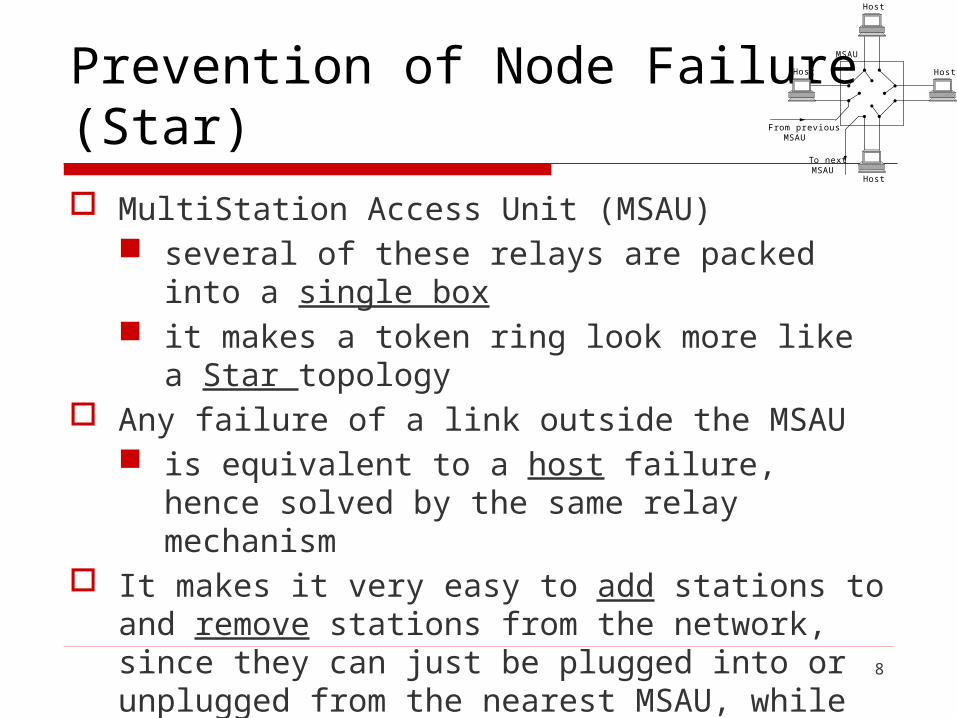
Prevention of Node Failure (Star)
MultiStation Access Unit (MSAU) several of these relays are packed into a single box it makes a token ring look more like a Star topology
Any failure of a link outside the MSAU is equivalent to a host failure, hence solved by the same
relay mechanism It makes it very easy to add stations to and remove stations
from the network, since they can just be plugged into or unplugged from the nearest MSAU, while the overall wiring of the network can be left unchanged
Host
Host
Host
Host
From previousMSAU
To nextMSAU
MSAU

9
Host
Host
Host
Host
From previousMSAU
To nextMSAU
MSAU
Multistation access unit

10
Token Ring Media Access Control
Media access control the network adaptor for a token ring contains a receiver and
a transmitter when a node is neither the source nor the destination of the
data on the ring, its adaptor is simply retransmitting the data that its receiver receives
when none of the stations connected to the ring has anything to send, the token circulates around the ring
any station that has data to send may "seize" the token, that is, not retransmit it and begin sending data
once a station has the token, it is allowed to send one or more packers
11
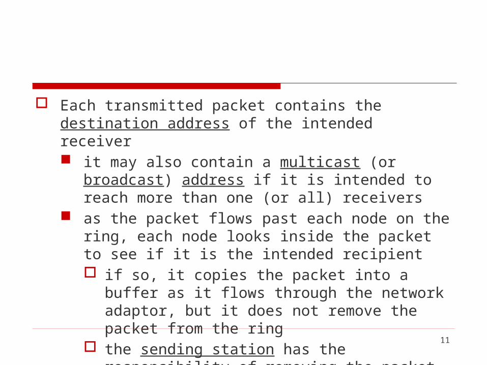
Each transmitted packet contains the destination address of the intended receiver it may also contain a multicast (or broadcast) address if it is
intended to reach more than one (or all) receivers as the packet flows past each node on the ring, each node
looks inside the packet to see if it is the intended recipient if so, it copies the packet into a buffer as it flows through
the network adaptor, but it does not remove the packet from the ring
the sending station has the responsibility of removing the packet from the ring

12
Token Holding Time (THT) how much data a given node is allowed to transmit each
time it possesses the token or, equivalently, how long a given node is allowed to hold the token (token holding time)
danger a single station could monopolize the ring for an
arbitrarily long time resolution
set the THT to significantly more than the time to send one packet
13
The more bytes a node can send each time it has the token, the better the utilization of the ring you can achieve in the situation in which only a single node has data to send
14
The downside, is that this strategy does not work well when multiple nodes have data to send, even when it is important to get this small message delivered as soon as possible

15
the 802.5 protocol's support for different levels of priority
the token contains a 3-bit priority field, so we can think of the token having a certain priority n at any time
each device that wants to send a packet assigns a priority to that packet, and the device can only seize the token to transmit a packet if the packet's priority is at least as great as the tokens
the priority of the token changes over time due to the use of three reservation bits in the frame header
16
example a station X waiting to send a priority n packet may
set these bits to n if it sees a data frame going past and the bits have not already been set to a higher value
station X is responsible for lowering the token priority to its old value when it is done

17
Strict priority scheme principle
no lower-priority packets get sent when higher-priority packets are waiting
this may cause lower-priority packets to be locked out of the ring for extended periods if there is a sufficient supply of higher-priority packets

18
Reliable delivery the 802.5 protocol provides a form of reliable delivery
using 2 bits in the packet trailer: the A and C bits (both 0 initially)
when a station sees a frame for which it is the intended recipient, it sets the A bit in the frame
when it copies the frame into its adapter, it sets the C bit if the sending station sees the frame come back over the
ring with the A bit still 0, it knows that the intended recipient is not functioning or absent
19
if the A bit is set but not the C bit, this implies that for some reason (e.g., lack of buffer space), the destination could not accept the frame
thus, the frame might reasonably be retransmitted later in the hope that buffer space had become available
20
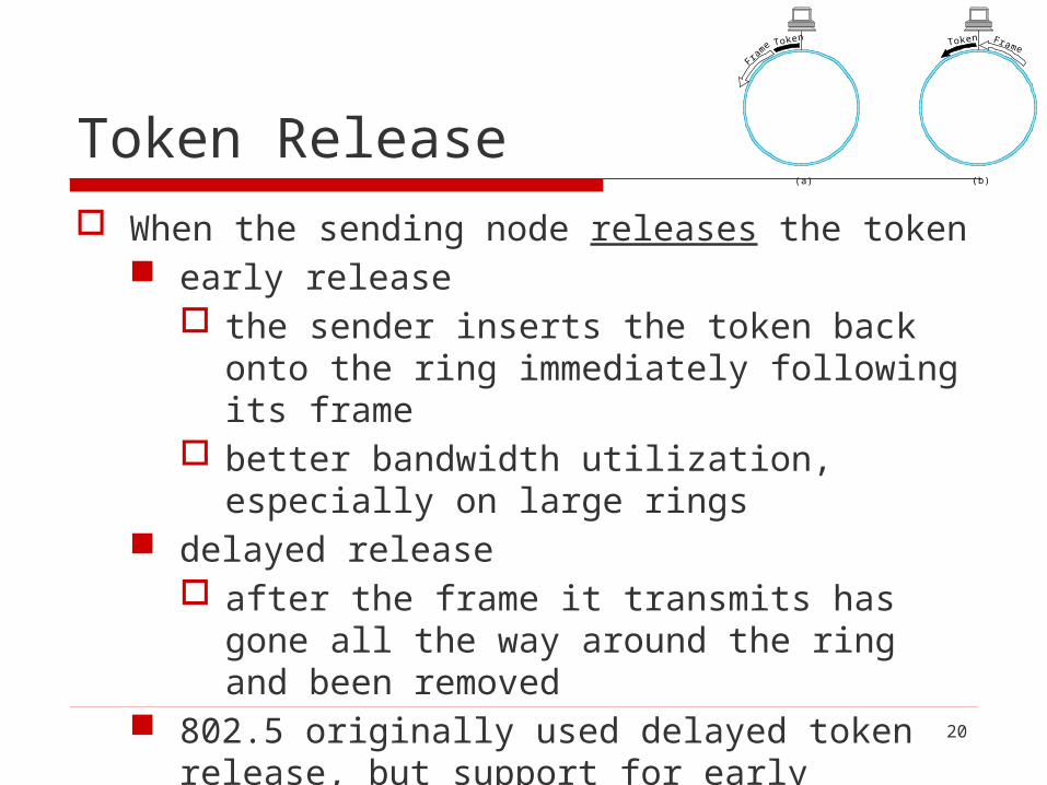
Token Release
When the sending node releases the token early release
the sender inserts the token back onto the ring immediately following its frame
better bandwidth utilization, especially on large rings delayed release
after the frame it transmits has gone all the way around the ring and been removed
802.5 originally used delayed token release, but support for early release was subsequently added
Token
Fram
e Token Frame
(a) (b)

21
Token
Fram
e Token Frame
(a) (b)
Token release: (a) early versus (b) delayed
22
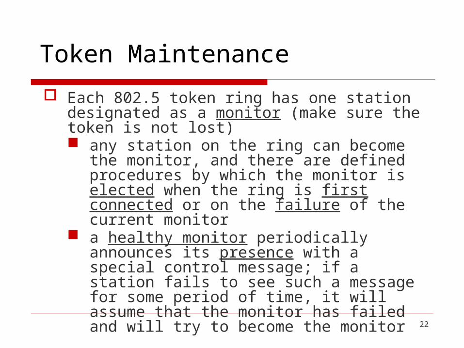
Token Maintenance
Each 802.5 token ring has one station designated as a monitor (make sure the token is not lost) any station on the ring can become the monitor, and
there are defined procedures by which the monitor is elected when the ring is first connected or on the failure of the current monitor
a healthy monitor periodically announces its presence with a special control message; if a station fails to see such a message for some period of time, it will assume that the monitor has failed and will try to become the monitor
23
when a station decides that a new monitor is needed, it transmits a “claim token” frame, announcing its intent to become the new monitor
if that token circulates back to the sender, it can assume that it’s okay for it to become the monitor
if some other station is also trying to become the monitor at the same instant, the sender might see a claim token message from that other station first
in this case, it will be necessary to break the tie using some well-defined rule like “highest address wins”

24
A token may vanish for several reasons no token when initializing ring bit error corrupts token pattern the node holding token crashes
To detect a missing token the monitor watches for a passing token and maintains a
timer equal to the maximum possible token rotation time, this interval equals
NumStations × THT+ RingLatency NumStations: the number of stations on the ring RingLatency: the total propagation delay of the ring
If the timer expires without the monitor seeing a token, it creates a new one
25
The monitor also checks for corrupted or orphaned frames corrupted frames
have checksum errors or invalid formats, and without monitor intervention, they could circulate forever on the ring
the monitor drains them off the ring before reinserting the token
orphaned frame the one that was transmitted correctly onto the ring but
whose “parent” died the sending station went down before it could remove the
frame from the ring
26
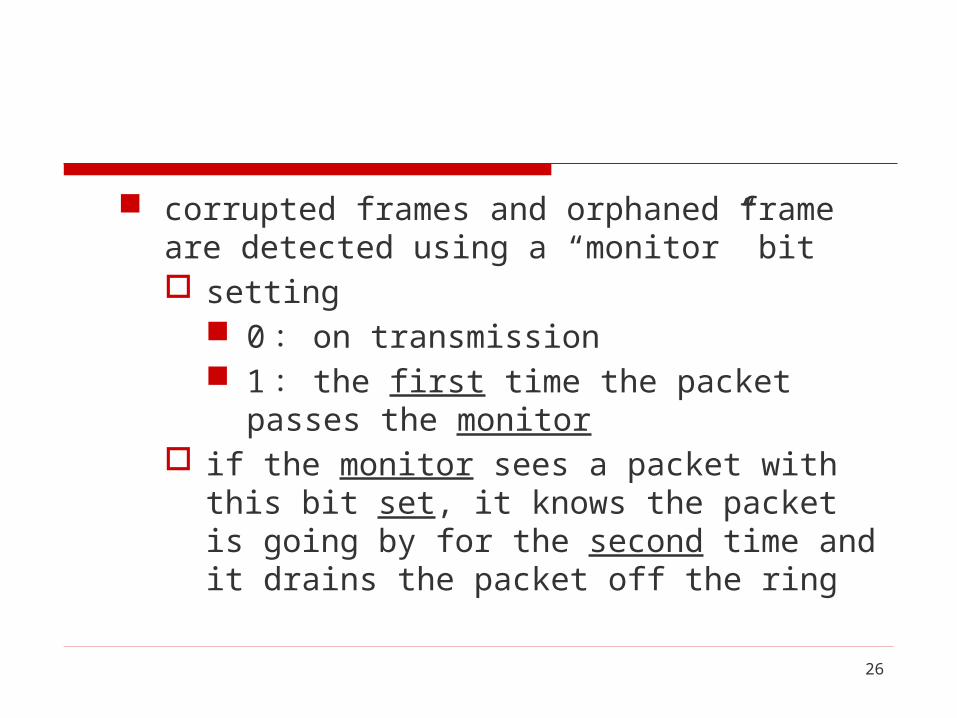
corrupted frames and orphaned frame are detected using a “monitor” bit setting
0 : on transmission 1 : the first time the packet passes the monitor
if the monitor sees a packet with this bit set, it knows the packet is going by for the second time and it drains the packet off the ring

27
Detection of dead stations case1
the relays in the MSAU can automatically bypass a station that has been disconnected or powered down
case2 if any station suspects a failure on the ring, it can
send a beacon frame to the suspect destination
28
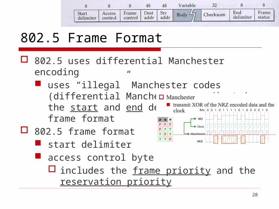
802.5 Frame Format
802.5 uses differential Manchester encoding uses “illegal” Manchester codes (differential
Manchester encoding) in the start and end delimiters of the frame format
802.5 frame format start delimiter access control byte
includes the frame priority and the reservation priority

29
frame control byte a demux key that identifies the higher-layer protocol
32-bit CRC frame status byte
includes the A and C bits for reliable delivery
802.5/token ring frame format

30
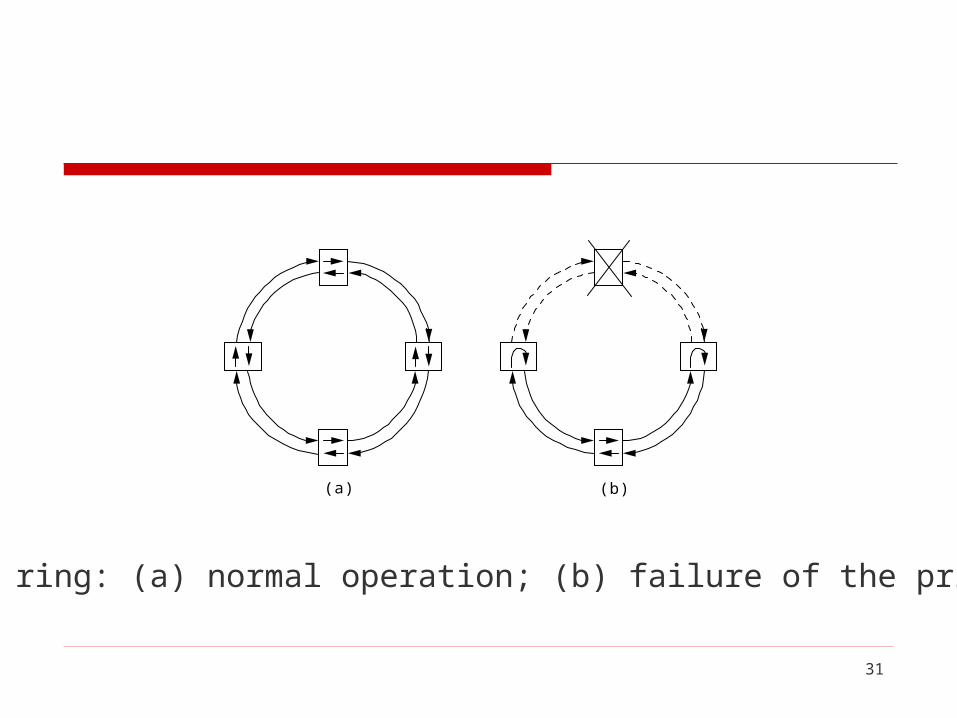
FDDI FDDI (Fiber Distributed Data Interface)
runs on fiber (not copper) consists of a dual ring
two independent rings that transmit data in opposite directions
the second ring is not used during normal operation but instead comes into play only if the primary ring fails that is, the ring loops back on the secondary fiber to
form a complete ring FDDI network is able to tolerate a single break in the
cable or the failure of one station
(a) (b)
31
(a) (b)
Dual-fiber ring: (a) normal operation; (b) failure of the primary ring

32
Resilient Packet Ring (RPR)
Resilient Packet Ring (RPR) has been standardized by the IEEE as 802.17
Design goals resiliency
the ability to recover quickly from a link or node failure
bandwidth efficiency quality of service (QoS) support
33
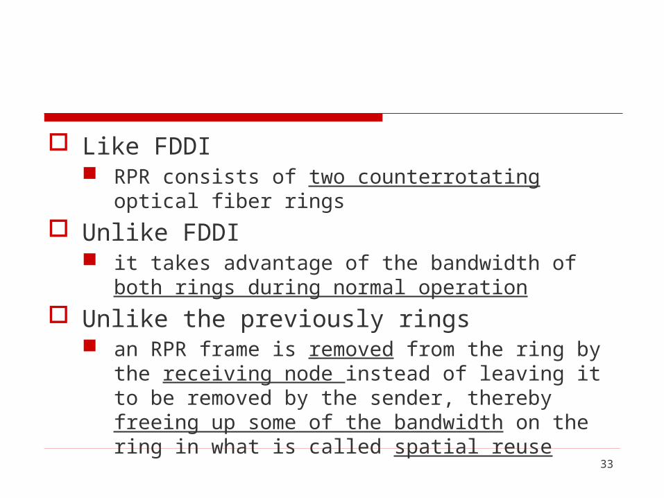
Like FDDI RPR consists of two counterrotating optical fiber rings
Unlike FDDI it takes advantage of the bandwidth of both rings during
normal operation
Unlike the previously rings an RPR frame is removed from the ring by the receiving
node instead of leaving it to be removed by the sender, thereby freeing up some of the bandwidth on the ring in what is called spatial reuse

34
Buffer insertion RPR does not use tokens RPR uses a technique called buffer insertion in a buffer insertion ring, a node can transmit its
own frames whenever it has no other frames to forward
if a frame arrives while the node is transmitting its own frame, then the node temporarily buffers that frame

35
RPR supports three QoS classes class A provides low latency and low jitter (e.g., for
phone calls) class B provides predictable latency and jitter (e.g.
for prerecorded multimedia) class C provides a best-effort transport...

36
To meet the resiliency goals, RPR uses two mechanisms to recover from the failure of a link or node wrapping
similar to the approach described above for FDDI steering
nodes adjacent to the failure notify the other nodes, which are then able to direct packets in the correct (unbroken) direction around the ring toward any given destination, even that is the “long” way around the ring

37
2.8 Wireless
Wireless technologies differ in a variety of dimensions how much bandwidth they provide how far apart communicating nodes can be which part of the electromagnetic spectrum they
use (including whether it requires a license) how much power they consume (important for
mobile nodes)
38
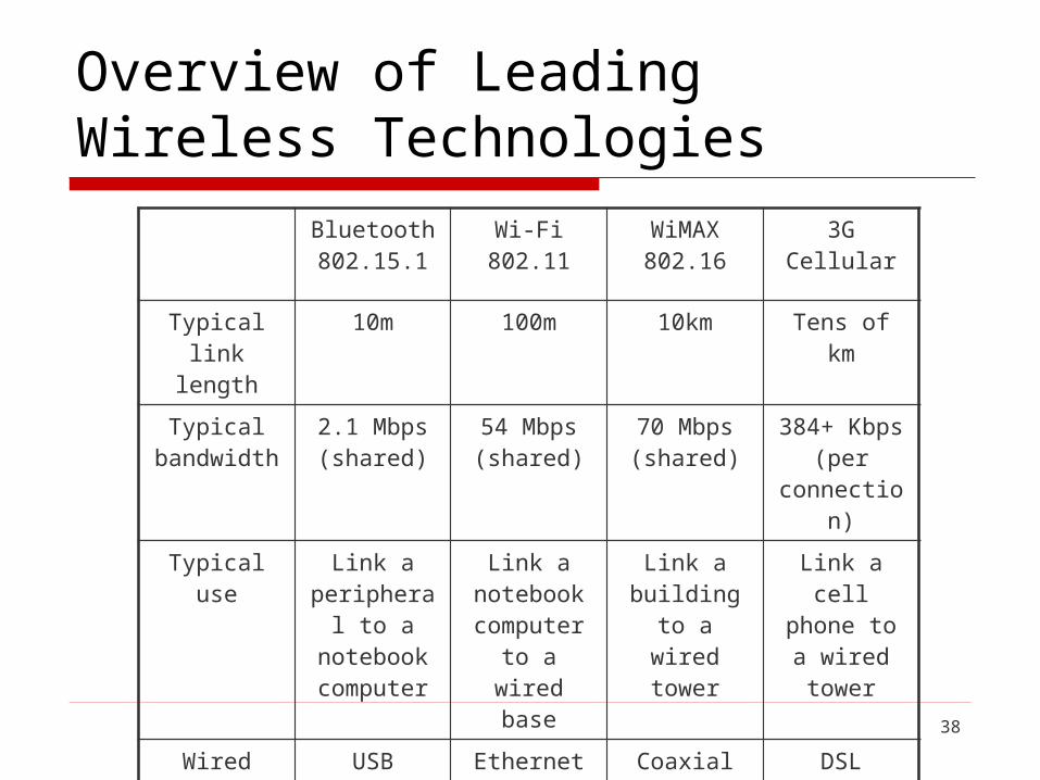
Overview of Leading Wireless Technologies
Bluetooth 802.15.1
Wi-Fi 802.11
WiMAX 802.16
3G Cellular
Typical link length
10m 100m 10km Tens of km
Typical bandwidth
2.1 Mbps (shared)
54 Mbps (shared)
70 Mbps (shared)
384+ Kbps (per
connection)
Typical use Link a peripheral
to a notebook computer
Link a notebook computer to a wired
base
Link a building to
a wired tower
Link a cell phone to a
wired tower
Wired technology
analogy
USB Ethernet Coaxial cable
DSL
39
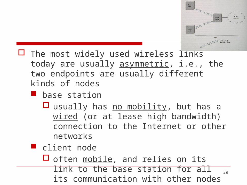
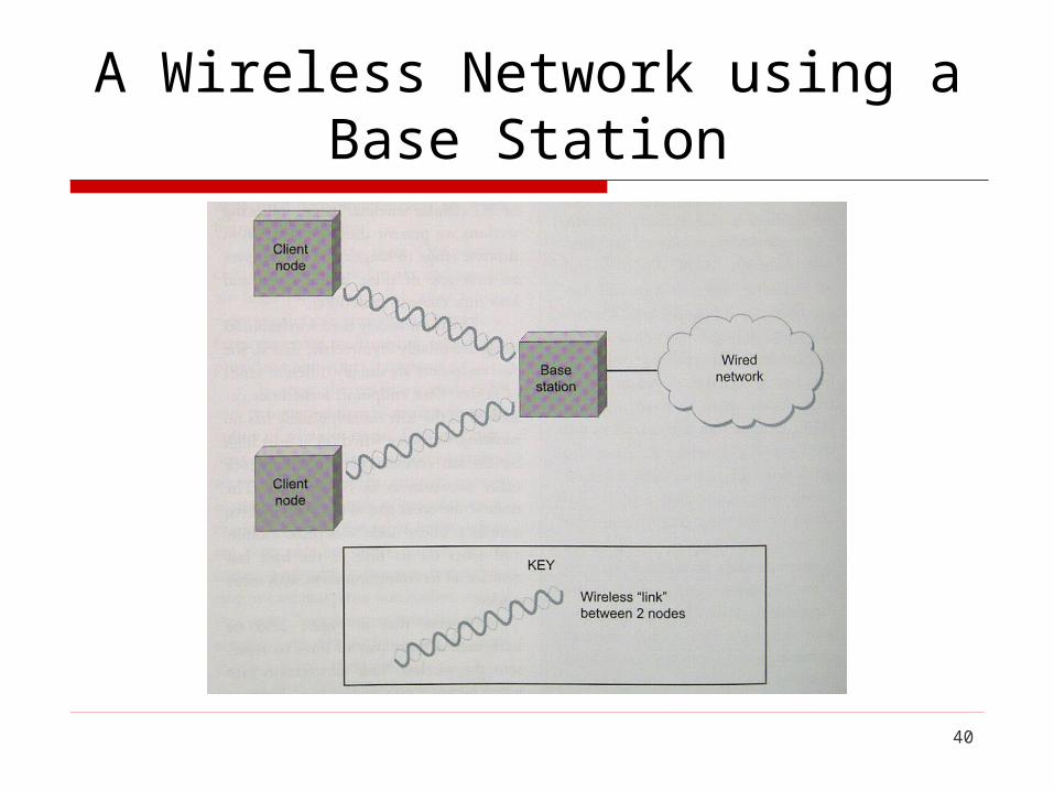
The most widely used wireless links today are usually asymmetric, i.e., the two endpoints are usually different kinds of nodes base station
usually has no mobility, but has a wired (or at lease high bandwidth) connection to the Internet or other networks
client node often mobile, and relies on its link to the base station
for all its communication with other nodes
40
A Wireless Network using a Base Station

41
This topology implies three qualitatively different levels of mobility the first level
no mobility such as when a receiver must be in a fixed location to
receive a directional transmission from the base station
example: the Initial version of WiMAX

Intel WiMAX Vision
42

WiMAX Consumer Last Mile
43

44
the second level mobility within the range of a base example: Bluetooth
the third level mobility between base stations examples: cell phones and Wi-Fi

45
An alternative topology is the mesh or ad hoc network nodes are peers (i.e., there is no special base station
node) messages may be forwarded via a chain of peer
nodes as long as each node is within range of the preceding node

46
A Wireless Ad Hoc or Mesh Metwork
47
This allows a shorter-range technology to extend its range and potentially compete with a longer range technology
Meshes also offer fault tolerance by providing multiple routes for a message to get from point A to point B
They still in their relative infancy compared to networks with base stations (so we do not cover them further here)
Four wireless technologies will be discussed here

48
Bluetooth
Bluetooth is specified by an industry consortium called the Bluetooth Special Interest Group
It specifies an entire suite of protocols, going beyond the link layer to define application protocols, which it calls profiles, for a range of applications example
there is a profile for synchronizing a PDA with a personal computer
another profile gives a mobile computer access to a wired LAN in the manner of 802.11, although this was not Bluetooth’s original goal

49
The IEEE 802.15.1 standard a Wireless Personal Area Network standard based on the
Bluetooth™ v1.1 Foundation Specifications Bluetooth provides a way to connect and exchange
information between short-range communication devices such as mobile phones, PDAs, laptops, PCs, printers,
digital cameras, and video game consoles over a secure, globally unlicensed short-range radio frequency

50
For Bluetooth applications, it is not necessary to provide much range or bandwidth power consumption is low version 2.0 provides speeds up to 2.1Mbps
Bluetooth is sometimes categorized as a personal area network (PAN)
it has a range of only about 10m

51
Air interface the protocol operates in the license-free ISM [Industrial,
Scientific and Medical] band at 2.4-2.4835 GHz to avoid interfering with other protocols that use the
2.45 GHz band, Bluetooth uses frequency hopping with 79 channels and changes channels up to 1600 times per second (each for 625μm at a time)
52
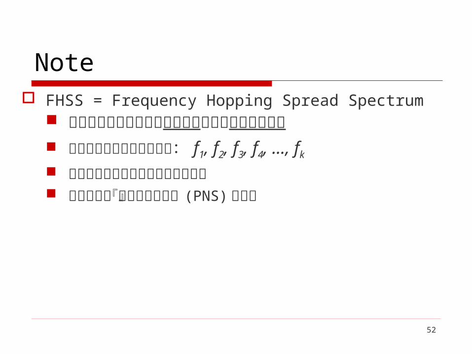
Note FHSS = Frequency Hopping Spread Spectrum
每位使用者傳送資料的載波頻率作近似不規則的切換 將頻道劃分為若干個小頻道: f1, f2, f3, f4, ..., fk 傳輸訊號在這些小頻道之間跳躍發送 跳躍順序由『虛擬雜訊序列』 (PNS) 所產生

53
Note (cont.)Frequency
f5
f4
f3
f2
f1
Frame Slot
Time

54
Note (cont.)
在同步且同時的情況下,接收兩端以特定型式的窄頻載波 (narrowband) 傳送訊號 FHSS 所產生的跳動訊號對非特定的接受器只是脈衝
雜訊 跳頻訊號須遵守 FCC (Federal
Communications Commission) 的規範

55
Communication and connection a master Bluetooth device can communicate with
up to seven slave devices this network group of up to eight devices is called a
piconet

56Bluetooth piconet

57
any communication is between the master and a slave the slaves do not communicate directly with each other Bluetooth provides a natural time slot for synchronous
time division multiplexing only the master can start to transmit in odd-
numbered slots a slave can start to transmit in an even-numbered
slot, but only in response to a request from the master during the previous slot, thereby preventing any contention between the slave devices

58
a slave device can be parked: set to an inactive, low-power state
a parked device cannot communicate on the piconet; it can only be reactivated by the master
a piconet can have up to 255 parked devices in addition to its active slave devices
http://en.wikipedia.org/wiki/Bluetooth

59
2.8.2 Wi-Fi (802.11)
This section takes a closer look at a specific technology centered around the IEEE 802.11 standard, also known as Wi-Fi.
Wi-Fi is owned by a trade group called the Wi-Fi alliance, that certifies product compliance with 802.11.

60
Physical properties
802.11 runs over six different physical layer protocol. Five are based on spread spectrum radio and one on
diffused infrared The fastest runs at a maximum of 54 Mbps

61
The original 802.11 standard defined two radio-based physical layers standards One using frequency hopping and the other using
direct sequence (both provide up to 2 Mbps)
Then physical layer standard 802.11b was added. Using a variant of direct sequence, 802.11b
provides up to 11 Mbps.
These three standards run in the license-exampt 2.4GHz frequency band

62
Then came 802.11a which delivers up to 54 Mbps using a variant of FDM called orthogonal frequency division multiplexing (OFDM)
802.11a runs in the license-exempt 5-GHz band On one hand, the band is less used, so there is less
interference On the other hand, there is more absorption of the
signal and it is limited to almost line of sight
63
802.11g is backward compatible with 802.11b and returns to the 2.4 GHz band
802.11g uses OFDM and delivers up to 54 Mbps
64
Collision Avoidance
It might seem that a wireless protocol would follow the same algorithm as the Ethernet– wait until the link becomes idle before transmitting and back off should a collision occur
To a first approximation, this is what 802.11 does
65
The additional complication for wireless is that, while a node on an Ethernet receives every other node’s transmissions, a node on an 802.11 network may be too far from certain other nodes to receive their transmissions (vice versa)

66
Hidden Node (Terminal) Problem
In the following figure A and C are both within range of B but not each
other suppose both A and C want to communicate with B
and so they each send it a frame A and C are unaware of each other since their
signals do not carry that far these two frames collide with each other at B and
neither A nor C is aware of this collision

67
A and C are said to be hidden nodes with respect to each other
only the receiver (node B) can help avoid collisions
Hidden node problem
68
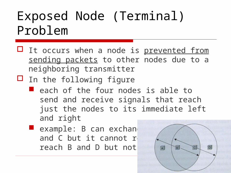
Exposed Node (Terminal) Problem
It occurs when a node is prevented from sending packets to other nodes due to a neighboring transmitter
In the following figure each of the four nodes is able to send and receive
signals that reach just the nodes to its immediate left and right
example: B can exchange frames with A and C but it cannot reach D; C can reach B and D but not A

69
suppose B is sending to A, node C is aware of this communication because it hears B’s transmission
it would be a mistake for C to conclude that it cannot transmit to anyone just because it can hear B’s transmission, for example, suppose C wants to transmit to node D
Note: C’s transmission to D will not interfere with B
sending to A C’s transmission would interfere with A sending to B

70
Exposed node problem
71
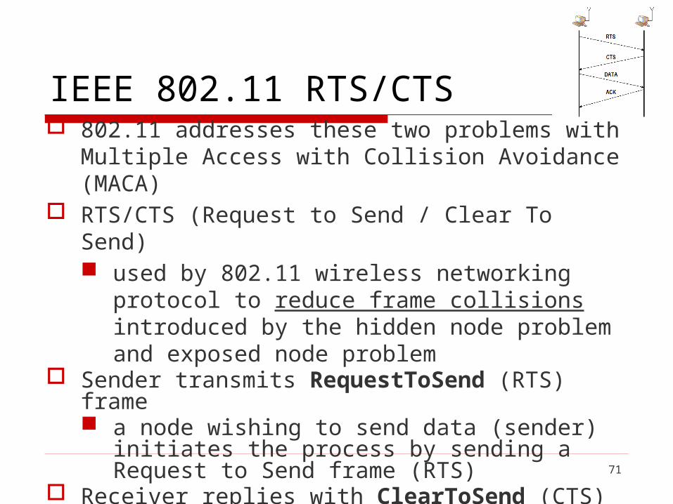
IEEE 802.11 RTS/CTS 802.11 addresses these two problems with Multiple Access
with Collision Avoidance (MACA) RTS/CTS (Request to Send / Clear To Send)
used by 802.11 wireless networking protocol to reduce frame collisions introduced by the hidden node problem and exposed node problem
Sender transmits RequestToSend (RTS) frame a node wishing to send data (sender) initiates the
process by sending a Request to Send frame (RTS) Receiver replies with ClearToSend (CTS) frame
the destination node (receiver) replies with a Clear To Send frame (CTS)
72
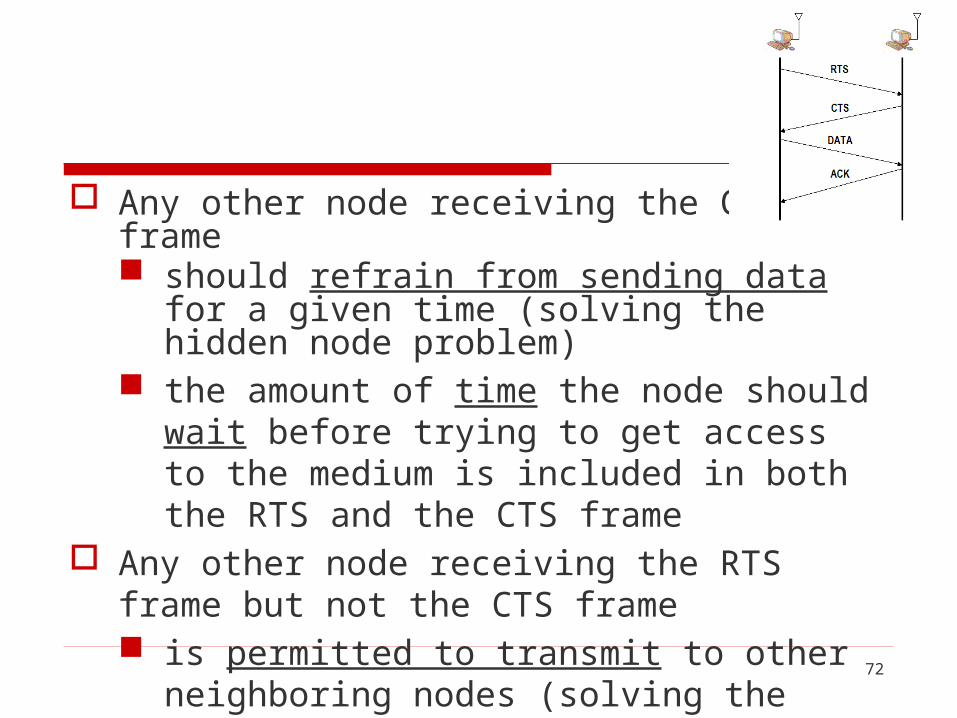
Any other node receiving the CTS frame should refrain from sending data for a given time
(solving the hidden node problem) the amount of time the node should wait before
trying to get access to the medium is included in both the RTS and the CTS frame
Any other node receiving the RTS frame but not the CTS frame is permitted to transmit to other neighboring nodes
(solving the exposed node problem)
73
The receivers sends an ACK to the sender after successfully receiving a frame all nodes must wait for this ACK before trying to
transmit If two or more nodes detect an idle link and try to
transmit an RTS frame at the same time RTS frames will collide with each other

74
802.11 does not support collision detection, but instead the senders realize the collision has happened when they do not receive the CTS frame after a period of time
the amount of time a given node delays is defined by the same exponential backoff algorithm used on the Ethernet


76
Distribution System
In stead of all nodes being created equal, some nodes are allowed to roam (e.g., your laptop) and some are connected to a wired network infrastructure
802.11 calls these base stations access points They are connected to each other by a so-called
distribution system

77
Distribution System
A distribution system that connects three access points (AP), each of which services the nodes in some region
Node A communicates (sending frame) with node E sending path: A → AP-1 → AP-3 → E
BH
A
F
G
D
AP-2
AP-3AP-1
C E
Distribution system
Access points connected to a distribution network

78
How does nodes select APs?
Scanning (selecting an AP) the node sends a Probe frame all APs within reach reply with a ProbeResponse
frame the node selects one of the access points, and sends that
AP an AssociationRequest frame the AP replies with an AssociationResponse frame
BH
A
F
G
D
AP-2
AP-3AP-1
C E
Distribution system
79
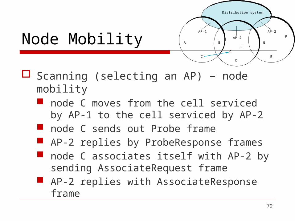
Node Mobility
Scanning (selecting an AP) – node mobility node C moves from the cell serviced by AP-1 to the cell
serviced by AP-2 node C sends out Probe frame AP-2 replies by ProbeResponse frames node C associates itself with AP-2 by sending
AssociateRequest frame AP-2 replies with AssociateResponse frame
BH
A
F
G
D
AP-2
AP-3AP-1
EC
C
Distribution system

80
BH
A
F
G
D
AP-2
AP-3AP-1
EC
C
Distribution system
Node mobility

81
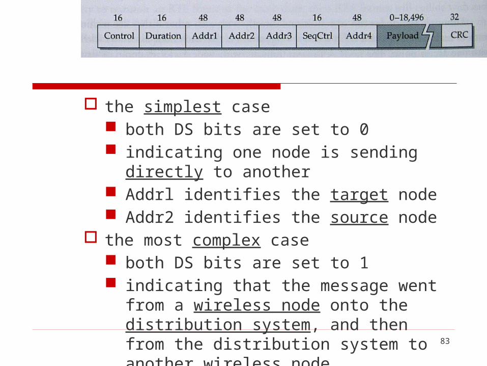
Frame Format
802.11 Frame Format Control : contains three subfields
Type (6 bits): indicates whether the frame carries data, is an RTS or CTS frame; or is being used by the scanning algorithm
ToDS (1 bit) FromDS (1 bit) others

82
Payload : up to 2312 bytes CRC : 32 bits source and destination node addresses (four
addresses) : all 48 bits these four addresses are interpreted depends on the
settings of the ToDS and FromDS bits in the frame’s Control field
this is to account for the possibility that the frame had to be forwarded across the distribution system
83
the simplest case both DS bits are set to 0 indicating one node is sending directly to another Addrl identifies the target node Addr2 identifies the source node
the most complex case both DS bits are set to 1 indicating that the message went from a wireless
node onto the distribution system, and then from the distribution system to another wireless node

84
Addrl identifies the ultimate destination Addr2 identifies the immediate sender (the one
that forwarded the frame from the distribution system to the ultimate destination)
Addr3 identifies the intermediate destination (the one that accepted the frame from a wireless node and forwarded it across the distribution system)
Addr4 identifies the original source

85
in terms of the previous example, Addrl corresponds to E Addr2 identifies AP-3 Addr3 corresponds to AP-1 Addr4 identifies A
BH
A
F
G
D
AP-2
AP-3AP-1
EC
C
Distribution system
Addr1
Addr2Addr3
Addr4