1 2 Assessment of Aframax Tanker 3 Hull-Girder … · 58(2007)3, 262-267 263 ASSESSMENT OF AFRAMAX...
43
262 58(2007)3, 262-267 UDC 629.5.015.4:629.5.023.121 Paul JURIŠIĆ 1 Joško PARUNOV 2 Ivo SENJANOVIĆ 3 Assessment of Aframax Tanker Hull-Girder Fatigue Strength According to New Common Structural Rules Original scientific paper The paper describes the fatigue strength assessment of ship hull girder according to Common Structural Rules for Oil Tankers (CSR). Additional criteria for hull girder fatigue calculation have recently been introduced into CSR because of frequent crack appearances on the main deck structure of large tankers. Hull girder fatigue check in CSR is performed in two steps: preliminary “fatigue section modulus” verification and detail fatigue calculation of deck longitudinals. The analysis is performed for an Aframax oil tanker fully complying with “old” rules of classification societies. Since the results of fatigue calculation for initial structure have not been found accept- able, a significantly increased hull section modulus is necessary as the only practical way for the deck longitudinal fatigue life improvement. In practice, the vertical wave bending moment at mid- ship, as the primary cause of hull girder fatigue damage, is calculated according to a simplified CSR formula. In order to improve the knowledge of its influence on the calculated fatigue life, the wave bending moment is also determined directly by a hydrodynamic and statistical analysis. In that analysis, the North Atlantic navigation is assumed as design wave environment for three predominant loading conditions. It is obvious that such an approach enables a more detailed and rational fatigue analysis than the one carried out according to the CSR rules. Keywords: Aframax tankers, bending moment, fatigue strength, hull girders, vertical waves Procjena zamorne izdržljivosti uzdužnjaka palube aframax tankera prema novim usuglašenim pravilima klasifikacijskih društava Izvorni znanstveni rad Opisan je postupak analize zamorne izdržljivosti brodskog trupa kao grednog nosača u području glavnog rebra prema novim usuglašenim pravilima klasifikacijskih društava (CSR). Kriteriji za zamornu izdržljivost grednog nosača su uvedeni u CSR pravila zbog učestalih pojavljivanja pukotina na palubnim strukturama velikih tankera. Provjera grednog nosača na zamornu izdržljivost u CSR se provodi u dva koraka: preliminarna provjera “zahtijevanog momenta otpora na zamor” i detaljni proračun zamora uzdužnjaka palube. Analiza je provedena za aframax tanker koji se gradi u skladu s postojećim pravilima klasifikacijskih društava. Budući da rezultati proračuna zamora postojeće konstrukcije nisu zadovoljili, znatno je povećan moment otpora poprečnog presjeka trupa, kao jedini izvediv način poboljšanja zamornog vijeka uzdužnjaka palube. U cilju daljnjeg produbljivanja znanja o ovom problemu, vertikalni moment savijanja na sredini broda, kao temeljni uzrok zamornog opterećenja uzdužnjaka palube, izračunat je, osim prema pojednostavljenim CSR izrazima, također i izravno hidrodinamičkom i statističkom analizom. U tu svrhu pretpostavljena je plovidba u Sjevernom Atlantiku cijelo vrijeme službe za tri prevladavajuća stanja krcanja broda. Pokazuje se da ovakav pristup omogućava podrobniju analizu zamora od one koja je propisana CSR pravilima. Ključne riječi: aframax tanker, moment savijanja, uzdužnjaci palube, vertikalni valovi, zamorna čvrstoća Authors’ addresses: 1 Croatian Register of Shipping, Marasovićeva 67, 21000 Split, e-mail: [email protected] 2 University of Zagreb, Faculty of Mechanical Engineering and Naval Architecture, I. Lučića 5, 10000 Zagreb, e-mail: [email protected] 3 University of Zagreb, Faculty of Mechanical Engineering and Naval Architecture, I. Lučića 5, 10000 Zagreb, e-mail: [email protected] Received (Primljeno): 2007-02-09 Accepted (Prihvaćeno): 2007-03-29 Open for discussion (Otvoreno za raspravu): 2008-09-30 1 Introduction The Common Structural Rules (CSR) for Double-Hull Oil Tankers have been developed by a group of IACS classification societies in response to a consistent and persistent call from industry for an increased standard of structural safety of oil tankers. The recently published statistics indicate a significant number of defects, especially fractures, occurring in tankers less than 10 years old. It is the intent of CSR rules to reduce the possibility of so many defects [1],[2]. New CSR rules implement advanced structural and hydrodynamic computational methods to establish new criteria applied in a consistent manner, which will result not only in a more robust, safer ship, but will also eliminate the possibility of using scantlings and steel weight as
Transcript of 1 2 Assessment of Aframax Tanker 3 Hull-Girder … · 58(2007)3, 262-267 263 ASSESSMENT OF AFRAMAX...

262 58(2007)3, 262-267
P. JURIŠIĆ, J. PARUNOV, I. SENJANOVIĆ ASSESSMENT OF AFRAMAX TANKER HULL-GIRDER FATIGUE STRENGTH...UDC 629.5.015.4:629.5.023.121
Paul JURIŠIĆ1
Joško PARUNOV2
Ivo SENJANOVIĆ3
Assessment of Aframax Tanker Hull-Girder Fatigue Strength According to New Common Structural Rules
Original scientifi c paper
The paper describes the fatigue strength assessment of ship hull girder according to Common Structural Rules for Oil Tankers (CSR). Additional criteria for hull girder fatigue calculation have recently been introduced into CSR because of frequent crack appearances on the main deck structure of large tankers. Hull girder fatigue check in CSR is performed in two steps: preliminary “fatigue section modulus” verifi cation and detail fatigue calculation of deck longitudinals. The analysis is performed for an Aframax oil tanker fully complying with “old” rules of classifi cation societies. Since the results of fatigue calculation for initial structure have not been found accept-able, a signifi cantly increased hull section modulus is necessary as the only practical way for the deck longitudinal fatigue life improvement. In practice, the vertical wave bending moment at mid-ship, as the primary cause of hull girder fatigue damage, is calculated according to a simplifi ed CSR formula. In order to improve the knowledge of its infl uence on the calculated fatigue life, the wave bending moment is also determined directly by a hydrodynamic and statistical analysis. In that analysis, the North Atlantic navigation is assumed as design wave environment for three predominant loading conditions. It is obvious that such an approach enables a more detailed and rational fatigue analysis than the one carried out according to the CSR rules.
Keywords: Aframax tankers, bending moment, fatigue strength, hull girders, vertical waves
Procjena zamorne izdržljivosti uzdužnjaka palube aframax tankera prema novim usuglašenim pravilima klasifi kacijskih društava
Izvorni znanstveni rad
Opisan je postupak analize zamorne izdržljivosti brodskog trupa kao grednog nosača u području glavnog rebra prema novim usuglašenim pravilima klasifi kacijskih društava (CSR). Kriteriji za zamornu izdržljivost grednog nosača su uvedeni u CSR pravila zbog učestalih pojavljivanja pukotina na palubnim strukturama velikih tankera. Provjera grednog nosača na zamornu izdržljivost u CSR se provodi u dva koraka: preliminarna provjera “zahtijevanog momenta otpora na zamor” i detaljni proračun zamora uzdužnjaka palube. Analiza je provedena za aframax tanker koji se gradi u skladu s postojećim pravilima klasifi kacijskih društava. Budući da rezultati proračuna zamora postojeće konstrukcije nisu zadovoljili, znatno je povećan moment otpora poprečnog presjeka trupa, kao jedini izvediv način poboljšanja zamornog vijeka uzdužnjaka palube. U cilju daljnjeg produbljivanja znanja o ovom problemu, vertikalni moment savijanja na sredini broda, kao temeljni uzrok zamornog opterećenja uzdužnjaka palube, izračunat je, osim prema pojednostavljenim CSR izrazima, također i izravno hidrodinamičkom i statističkom analizom. U tu svrhu pretpostavljena je plovidba u Sjevernom Atlantiku cijelo vrijeme službe za tri prevladavajuća stanja krcanja broda. Pokazuje se da ovakav pristup omogućava podrobniju analizu zamora od one koja je propisana CSR pravilima.
Ključne riječi: aframax tanker, moment savijanja, uzdužnjaci palube, vertikalni valovi, zamorna čvrstoća
Authors’ addresses:1 Croatian Register of Shipping,
Marasovićeva 67, 21000 Split, e-mail: [email protected] University of Zagreb, Faculty of
Mechanical Engineering and Naval Architecture, I. Lučića 5,
10000 Zagreb, e-mail: [email protected] University of Zagreb, Faculty of
Mechanical Engineering and Naval Architecture, I. Lučića 5,
10000 Zagreb, e-mail: [email protected]
Received (Primljeno): 2007-02-09Accepted (Prihvaćeno): 2007-03-29Open for discussion (Otvoreno za raspravu): 2008-09-30
1 Introduction
The Common Structural Rules (CSR) for Double-Hull Oil Tankers have been developed by a group of IACS classifi cation societies in response to a consistent and persistent call from industry for an increased standard of structural safety of oil tankers. The recently published statistics indicate a signifi cant
number of defects, especially fractures, occurring in tankers less than 10 years old. It is the intent of CSR rules to reduce the possibility of so many defects [1],[2]. New CSR rules implement advanced structural and hydrodynamic computational methods to establish new criteria applied in a consistent manner, which will result not only in a more robust, safer ship, but will also eliminate the possibility of using scantlings and steel weight as

26358(2007)3, 262-267
ASSESSMENT OF AFRAMAX TANKER HULL-GIRDER FATIGUE STRENGTH... P. JURIŠIĆ, J. PARUNOV, I. SENJANOVIĆ
a competitive element when selecting a class society to approve a new design.
Possibly, the most important new CSR rule requirement is the one for ultimate vertical bending moment capacity of hull-girder, which was not prescribed in previous versions of ship classifi ca-tion rules (with the exception of the Rules of Bureau Veritas that adopted the ultimate strength criterion in the year 2000 [3]). A “net” thickness approach is also an important new feature of CSR, where the structural capacity for different failure modes is to be calculated by assuming that the thickness of structural elements is reduced because of corrosion effects. CSR proposes a corrosion deduction thickness for different structural elements and different levels of calculation. Design scantlings of structural elements are then obtained by adding this corrosion deduction thickness to the minimum calculated “net” thickness.
Fatigue and corrosion are recognized as predominant factors which contribute to the structural failure observed on a ship in service. Fatigue may be defi ned as a process of cycle by cycle accumulating of damage in a structure subjected to fl uctuating stresses. Until recently, the fatigue was considered as a service-ability problem rather than a hull girder strength problem [4], [5]. However, the latest researches conducted for the development of the new CSR showed that the majority of cracks are caused not only by local dynamic loads but also by global dynamic loads such as the wave bending moment. In other words, fatigue of the hull girder may be a governing strength criterion for oil tankers, in particular if higher tensile steel is implemented [6].
The aim of the present paper is to present the hull-girder fatigue analysis of an existing Aframax oil tanker according to new CSR.
A brief description of the Aframax tanker used in the present study is given in the fi rst section of the paper. The fol-lowing section describes the methodology proposed by CSR for fatigue life calcula-tion of deck longitudinals of a double hull oil tanker. The next section presents results of the application of previously presented methodology to the Aframax tanker, showing that the fatigue life of the deck structure is signifi cantly below 25 years. Although the fatigue life in general depends on many factors, such as design shape of structural details, material grade, scantlings of details, etc., a decrease in fatigue stresses is found to be the only conven-ient way to improve the global fatigue behaviour. Therefore, the section modulus of midship section is to be increased in order to reduce fl uctuating stresses and to improve the fatigue behaviour of a ship as a hull girder. Finally, in the last section of the paper, the wave bending moment, as a primary cause of fatigue in the deck structure of oil tankers, is calculated by a direct hydrody-namic and statistical analysis using the linear strip theory and the IACS Recommendation No. 34 for extreme wave loads [7]. The obtained results are compared to those obtained by a pure “rule” approach and corresponding conclusions are drawn.
The main conclusion of the study is that a satisfactory fatigue life may be achieved only by a signifi cant increase in the midship section modulus. Therefore, the study supports the opinion that fatigue becomes a governing criterion in ship design, requiring a lot of additional steel-weight to be added to the hull structure.
2 Ship description
The ship analyzed in the present study is an existing Aframax oil tanker with the centre line plane bulkhead fully complying with “old” rules for the design and construction of steel ships, including IACS UR S11. The main particulars of the Aframax tanker are presented in Table 1. Deck and bottom areas of the ship are made of higher tensile steel AH32, while the region around the neutral axis is made of mild steel ST235. Since this tanker has the ICE-1C class notation, the side shell in the ice belt region is made of higher tensile steel AH36. In addition, the whole center line bulkhead is made of higher tensile steel AH32 due to shear stress requirements.
The general arrangement of the vessel is shown in Figure 1, while the midship section of the vessel is presented in Figure 2.
Table 1 Main characteristics of the Aframax tankerTablica 1 Osnovne značajke aframax tankera
Length between perpendiculars, Lpp 236 m
Moulded breadth, B 42.0 m
Moulded depth, D 21.0 m
Scantling draught, T 15.6 m
Deadweight, DWT 114000 dwt
Figure 2 Midship section of the Aframax tankerSlika 2 Glavno rebro aframax tankera
Figure 1 Aframax tanker Slika 1 Aframax tanker
264 58(2007)3, 262-267
P. JURIŠIĆ, J. PARUNOV, I. SENJANOVIĆ ASSESSMENT OF AFRAMAX TANKER HULL-GIRDER FATIGUE STRENGTH...
3 Fatigue in CSR
Hull girder fatigue calculations in CSR are performed in two steps: a simplifi ed check of hull girder fatigue section modulus and a detailed fatigue life assessment of main deck longitudinals. These two calculation methods are briefl y described in the fol-lowing sections.
3.1 Hull girder fatigue requirement
Hull girder fatigue strength is checked by a simplifi ed fatigue control measure against dynamic hull girder stresses in the lon-gitudinal deck structure. The required hull girder fatigue section modulus Z
v-fat (m3) is given in CSR, Section 8.1.5:
(1)
Mwv-hog
= hogging vertical wave bending moment for fatigue (kNm)
Mwv-sag
= sagging vertical wave bending moment for fatigue (kNm)
Ral = allowable stress range (N/mm2) R
al = 0.17L+86 for class F-details (2)
The actual section modulus to be compared to the minimum required value Z
v-fat is calculated by deducting half of the rule cor-
rosion wastage (-0.5tcorr
) from the gross thickness of all structural elements contributing to the hull girder longitudinal strength. It should be pointed out that this requirement is not mandatory, but recommended to be applied in the early design stage in order to avoid signifi cant reinforcements in the later design stage when detailed fatigue calculations are carried out.
Hogging and sagging vertical wave bending moments for fatigue are obtained by multiplying rule wave bending mo-ments for strength assessment by a factor of 0.5. In that way, the representative probability level of wave bending moments is reduced from 10-8 to 10-4. This aspect is described in CSR Section 7.3.4.1.3.
3.2 Detailed fatigue assessment of deck longitudinals
The calculation of hull girder stress for the detailed fatigue strength assessment of deck longitudinals is based on the fatigue hull girder sectional proprieties calculated by deducting a quarter of the corrosion addition (-0.25 t
corr) from the gross thickness of
all structural elements comprising the hull girder cross section. The capacity of welded steel joints with respect to fatigue
strength is characterized by the Wöhler curves (S-N curves) which give the relationship between the stress ranges applied to a given detail and the number of constant amplitude load cy-cles to failure, with the zero mean stress. The hull detail which is taken into consideration for the fatigue assessment of deck structure is the connection of a deck longitudinal and a typical web frame, classed as F-detail, CSR Table C.1.7-Classifi cation of Structural Details.
The fatigue assessment of the structural details is based on the application of the Palmgren-Miner cumulative damage rule.
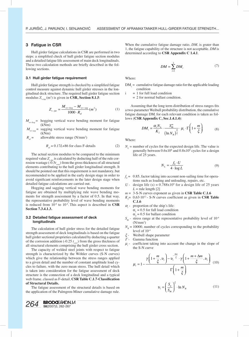
When the cumulative fatigue damage ratio, DM, is grater than 1, the fatigue capability of the structure is not acceptable. DM is determined according to CSR Appendix C 1.4.1.
(7)
Where:
DMi = cumulative fatigue damage ratio for the applicable loading
condition i = 1 for full load condition = 2 for normal ballast condition.
Assuming that the long term distribution of stress ranges fi ts a two-parameter Weibull probability distribution, the cumulative fatigue damage DM
i for each relevant condition is taken as fol-
lows (CSR Appendix C, Sec.1.4.1.4):
(8)
Where:
NL = number of cycles for the expected design life. The value is
generally between 0.6x10⁸ and 0.8x10⁹ cycles for a design life of 25 years.
(9)
f0 = 0.85, factor taking into account non-sailing time for opera-
tions such as loading and unloading, repairs, etc.U - design life (s) = 0.788x10⁹ for a design life of 25 years
L = rule length [2]m = 3-S-N curves exponent as given in CSR Table C.1.6K
2= 0,63·1012 - S-N curves coeffi cient as given in CSR Table
C.1.6α
i - proportion of the ship’s life:
α1 = 0.5 for full load condition
α2 = 0.5 for ballast condition
SRi
- stress range at the representative probability level of 10-4
(N/mm2) N
R = 10000, number of cycles corresponding to the probability
level of 10-4 ξ - Weibull shape parameter Γ - Gamma function µ
i - coeffi cient taking into account the change in the slope of
the S-N curve
(10)
(11)
ZM M
Rmv fat
wv hog wv sag
al−
− −=−⋅1000
3( )
DM DMii
==∑
1
2
DMN
K
S
N
mi
i L Rim
R
m i= ⋅( )
⋅ ⋅ +⎛⎝⎜
⎞⎠⎟
α µξξ2
1ln
Γ
Nf U
LL = ⋅⋅0
4 log
µγ
ξυ υ γ
ξυξ
i
i i
m
i
m m m
= −+
⎛⎝⎜
⎞⎠⎟
− ⋅ + +⎛⎝⎜
⎞⎠
−
1
1 1, ,∆ ∆
⎟⎟
+⎛⎝⎜
⎞⎠⎟
Γ 1m
ξ
υξ
iq
RiR
S
SN=
⎛⎝⎜
⎞⎠⎟
⋅ ln

26558(2007)3, 262-267
ASSESSMENT OF AFRAMAX TANKER HULL-GIRDER FATIGUE STRENGTH... P. JURIŠIĆ, J. PARUNOV, I. SENJANOVIĆ
Sq - stress range at the intersection of two segments (“knee”)
of the S-N curves, CSR Table C.1.6.∆
m = 2 - slope change of the upper-lower segment of the S-N
curveγ(a, x) - incomplete Gamma function, Legendre form
The Weibull shape parameter ξ is calculated as:
(12)
The cumulative fatigue damage ratio, DM, is fi nally converted into a calculated fatigue life:
(13) According to CSR requirements, the calculated fatigue life
should be more than 25 years.
4 Result of the analysis
Stress range SRi
, required for the calculation of accumulated damage in Eq. (8), is calculated by the simple beam theory as-sumptions, i.e.:
(14)
where Zv-net75
is the “net” section modulus (-0.25 tcorr
) of the mid-ship cross section, while M
Ri is the range of wave bending moment
at a representative probability level of 10-4. MRi
is calculated as:
(15)
where Mwv-hog
and Mwv-sag
are hogging and sagging vertical wave bending moments for fatigue, respectively, as given in CSR Section 7.3.4.1.3. For the Aframax tanker analysed in the present paper, the range of the vertical wave bending moment reads 3864 MNm. It should be noted that the stress range and all calculation parameters are the same for ballast and full load conditions. Consequently, the same results have been obtained for both conditions.
4.1 Initial structure
The existing “net” section modulus of the midship section calculated with the appropriate corrosion deduction, CSR Table 6.3.1-Corrosion addition, should be over the CSR minimal required fatigue section modulus. However, as may be seen from the results presented in Table 2, the actual section modulus should be increased by more than 15% to comply with the CSR minimal required value.
Table 2 Fatigue section modulus calculation for “initial” struc-ture
Tablica 2 Proračun “zamornog” momenta otpora početne kon-strukcije trupa
"Initial" structure
Actual sectional area, Av (m2) 4.97
Actual section modulus, Zv (m3) 26.59
Allowable fatigue stress, Ral
(N/mm2) 125.7Required fatigue section modulus, Z
v-fat (m3) 30.75
Input parameters and results of detailed fatigue calculations are presented in Table 3. As it can be seen, calculated fatigue life is estimated to 13.1 years, being much lower than the minimum requested fatigue life of 25 years.
Table 3 Fatigue damage calculation for “initial” structureTablica 3 Proračun zamora materijala početne konstrukcije
trupa
Mw
(MNm)N
L α ξ K2
SRi
(N/mm2)DM
iDM
Fatigue life
(years)
3864 7.069·107 0.5 0.944 0.63·1012 145.3 0.951 1.901 13.1
4.2 Reinforced structure
Since the initial design of Aframax structure has the fatigue life of much less than 25 years for the North Atlantic navigation, it is necessary to introduce some reinforcements. The only reason-able way to increase the fatigue life of deck longitudinals is to reduce the stress range S
Ri by increasing the ship section modulus.
For that purpose, the following reinforcements are proposed: • Changing deck longitudinals from HP280x11 to T400x15/
120x10• Increasing the thickness of the main deck plate from 17.5 mm
to 19.5 mm. These reinforcements are suffi cient to satisfy the hull girder
fatigue strength, as it can be seen from results in Table 4.
Table 4 Fatigue section modulus calculation for a “reinforced” structure
Tablica 4 Proračun “zamornog” momenta otpora pojačane kon-strukcije trupa
“Reinforced” structure
Actual sectional area, Av (m2) 5.30
Actual section modulus, Zv (m3) 31.74
Allowable fatigue stress, Ral
(N/mm2) 125.7
Required fatigue section modulus, Zv-fat
(m3) 30.75
Also, the detailed fatigue calculation of reinforced structure leads to a fatigue life of deck longitudinals of 25 years, which is satisfactory in accordance with the CSR (Table 5).
Table 5 Fatigue damage calculation for a “reinforced” struc-ture
Tablica 5 Proračun zamora materijala pojačane konstrukcije trupa
Mw
(MNm)N
L α ξ K2
SRi
(N/mm2)DM
iDM
Fatigue life
(years)
3864 7.069·107 0.5 0.944 0.63·1012 121.8 0.5 1.0 25.0
5 Fatigue analysis with loads from the hydro-dynamic analysis
The vertical wave bending moment is the dominant dynamic loading component for the hull girder fatigue analysis. New CSR continue using simple IACS UR S11 formulae for the design
ξ = ⋅ − ⋅ −⎛⎝⎜
⎞⎠⎟f
LWeibull 1 1 0 35
100
300. .
Fatigue lifeDesign life
DM
(years)=
SM
ZRiRi
v net
=− 75
M M MRi wv hog wv sag= −− −

266 58(2007)3, 262-267
P. JURIŠIĆ, J. PARUNOV, I. SENJANOVIĆ ASSESSMENT OF AFRAMAX TANKER HULL-GIRDER FATIGUE STRENGTH...
wave bending moments in sagging and hogging. The rule verti-cal wave bending moments are defi ned as the bending moments with the exceeding probability of 10-8. In other words, the rule values are the most probable extreme values for the return period of 20 years, which is the ordinary ship lifetime. The rule design wave bending moments are based on the main dimensions of the ship: length, breadth and block coeffi cient. Operational profi le, mass distribution and hull form are not taken into account by the rule formulae.
As an alternative to the application of IACS UR S11, a direct hydrodynamic analysis of ship motion and load may be performed to determine the long term distribution of wave bending moments for fatigue assessment. The direct analysis requires more detailed and elaborated input data and it is of interest to see its implication on the hull girder fatigue life.
Evaluation of the wave-induced load effects that occur dur-ing long-term operation of the ship in a seaway was carried out for sea areas in the North Atlantic in accordance with the IACS Recommendation Note No.34. Although this recommendation is basically concieved as guidance for the computation of extreme wave loads, it seems to be appropriate for fatigue analysis as well [7]. The basic assumptions proposed by IACS for the calculation of long-term extreme values of wave bending moments are:
• The IACS North Atlantic scatter diagram should be used. This scatter diagram covers areas 8, 9, 15 and 16, as defi ned in Global Wave Statistics (GWS). The data from the GWS are fur-ther modifi ed by IACS in order to take into account the limited wave steepness more properly.
• Only ship speed equal to zero is to be taken into account.
• The two-parameter Pierson-Moskowitz spectrum (ITTC spectrum) is recom-mended.
• Short-crested waves with the wave energy spreading function proportional to cos2(υ) are to be used.
• All heading angles should have equal probability of occurrence and maximally 30° spacing between headings should be applied.
The calculation of transfer functions of wave-in-duced load effects is performed by the program WAVE-SHIP, based on the linear strip theory [8]. The strip model of Aframax tanker is shown in Figure 3, while the transfer functions of vertical wave bending moments for the full load condition and different headings are presented in Figure 4.
The long-term analysis according to IACS procedure is performed for three loading conditions: full load (FL), ship in ballast (BL) and partial loading condition (PL). The long-term analysis is performed by the computer program POSTRESP, which is a part of the SESAM package [9]. After that, the range of wave bending moments corresponding to the probability level of 10-4 required for fatigue analysis is easily determined. Pa-rameters of Weibull distribution, used to approximate
the long-term probability distribution of vertical wave bending moment, are also computed easily.
Fatigue analysis according to CSR considers that the tanker spends 85% of the time on sea, equally in ballast and full load condition. In the direct analysis, the partial loading condition is also considered. The percentage of time that a ship spends in either of these loading conditions may be estimated based upon the statistical analysis of load duration data for tankers performed by Guedes Soares [10], as presented in Table 6.
Finally, it should be mentioned that the results from hy-drodynamic analysis are reduced by 10% for the application in fatigue calculation. This reduction is a consequence of the fact that the wave bending moments determined by linear strip theory overestimate the measured wave bending moments in average by 10% [11].
Input parameters and results of the detailed fatigue analysis of deck longitudinals are presented in Table 7. Calculated fatigue life is estimated to be 16.6 years, which is lower comparing to the CSR approach. It can be seen from Table 7 that the full load condition gives the largest contribution to the total fatigue damage.
a) looking from aft and above b) looking from bow and belowa) pogled s krme odozgo b) pogled s pramca odozdo
Figure 3 Hydrodynamic “strip” model of Aframax tankerSlika 3 Hidrodinamički “vrpčasti” model aframax tankera
Figure 4 Transfer functions of vertical wave bending moment at midship section for full load condition; Fn=0; µ =0o, 45o, 90o, 155o, 180o
Slika 4 Prijenosne funkcije vertikalnog valnog momenta savijanja glavnog rebra za stanje nakrcanog broda; Fn=0; µ =0o, 45o, 90o, 155o, 180o

26758(2007)3, 262-267
ASSESSMENT OF AFRAMAX TANKER HULL-GIRDER FATIGUE STRENGTH... P. JURIŠIĆ, J. PARUNOV, I. SENJANOVIĆ
Table 6 Operational profi le adopted for tankersTablica 6 Pretpostavljeni scenarij službe tankera
Load cond. Harbour Full Ballast Partial
Percentage of spent time 15% 35% 35% 15%
Voyage duration (days) ----------- 23.5 23.5 2.0
Table 7 Fatigue damage calculation as a result of hydrodynamic analysis for the reinforced structure.
Tablica 7 Proračun zamora materijala na osnovi rezultata hidro-dinamičke analize za pojačanu konstrukciju trupa
Full Ballast Partial
Mw (MNm) 4850 4470 4848
NL
7.44·107 7.73·107 7.58·107
α 0.35 0.35 0.15
ξ 0.992 0.969 0.977
K2
0.63·1012 0.63·1012 0.63·1012
SRi
(N/mm2) 137.55 126.77 137.48
DMi
0.706 0.503 0.302
DM 1.511
Fatigue life 16.55 (years)
6 Conclusion
The purpose of the paper is to point out that the fatigue failure is recognised as one of the governing failure modes in newly developed CSR for Double Hull Oil Tankers. Thus, fatigue is not only important for design of ship structural details, but also may be a governing criterion for the required section modulus at midship, i.e. for ship longitudinal strength, affecting thus the overall dimensions of structure subjected to fatigue.
Fatigue analysis of the connection of the main deck longi-tudinals and transverse web girders shows that the overall steel weight increase of 6.2% (620 tons increase for about 10000 weight of cargo hold area) would be necessary to reinforce the existing Aframax tanker to comply with the new CSR hull girder fatigue requirements.
It is shown in the paper that the non-mandatory hull girder fa-tigue strength criterion from CSR should be seriously considered in the early design stage. Otherwise, detailed fatigue calculations of the main deck longitudinals, which are normally carried out in a later stage, could lead to unsatisfactory results.
Finally, the paper proposes the methodology of how to effi -ciently use the results of the direct hydrodynamic analysis in the fatigue calculations. This could lead to more refi ned and more rational results of the fatigue analysis. To use direct calculation methods in the most effi cient way, fatigue reliability could be employed to take into consideration various uncertainties in the
load and the structural capacity and to estimate the probability of structural failure.
It should be mentioned that only the fatigue induced by the vertical wave bending moment is considered in this paper. There-fore, the presented results are relevant mostly for the main deck longitudinals in the centre-line area. To analyse the fatigue load of the main deck longitudinals located close to the side shell, the horizontal wave bending moment should be considered together with a statistical combination of vertical and horizontal wave bending moments. Such considerations are outside the scope of the present study. The same conclusion is valid for the connec-tion of side shell longitudinals with web frames and transverse bulkheads, which are among the most important ship structural details from the fatigue point of view [12]. Since the governing fatigue loading of side shell longitudinals is the local dynamic pressure, a signifi cantly different approach would be necessary, which is outside the scope of the present study.
References
[1] …“Structural Defect Experience for Tankers”, American Bureau of Shipping, Det Norske Veritas, Lloyd’s Register, 2005.
[2] …“Common Structural Rules for Double Hull Oil Tankers”, American Bureau of Shipping, Det Norske Veritas, Lloyd’s Register, 2006.
[3] …”Rules for Classifi cation of Steel Ships”, Bureau Veritas, Paris, 2000.
[4] ALMAR-NAESS, A.: “Fatigue Handbook-Offshore Struc-tures”, Tapir, Trondheim, 1985.
[5] BACH-GANSMO, O., CARLESEN, C.A.: “Fatigue as-sessment of hull girder for ship type fl oating production vessel”, Proceedings of the Mobile Offshore Structures, L.R. Baswall, C.A. D’Mello, A.J. Edwards Eds., Elsevier Science Ltd., 1989, p.297-319.
[6] TOMAŠEVIĆ, S., PARUNOV, J., SENJANOVIĆ, I.: “Fa-tigue Strength Assessment of FPSO Deck Longitudinals”, Trans. FAMENA, 2000, p.35-44.
[7] IACS recommendation note No.34: “Standard Wave Data”, 2000.
[8] …”WAVESHIP”, SESAM User’s Manual, Det Norske Veritas, Oslo, 2000.
[9] …”POSTRESP”, SESAM User’s Manual, Det Norske Veritas, Oslo, 2004.
[10] GUEDES SOARES, C.: “Infl uence of Human Control on the Probability Distribution of Maximum Still-Water Load Ef-fects in Ships”, Marine Structures, 3(1990)4, p.319-339.
[11] PARUNOV, J., SENJANOVIĆ, I.: “Incorporating Model Uncertainty in Ship Reliability Analysis”, Trans. SNAME 2003, Vol.111, p.377-408.
[12] LOTSBERG, I., LANDET, E.: “Fatigue capacity of side longitudinals in fl oating structures”, Marine Structures 18(2005)1, p.25-42.

1
CHALLENGES IN HYDRODYNAMICS OF SHIPS AND OCEAN STRUCTURES
by Odd M.Faltinsen
06/05/2007 20:00
ABSTRACT Violent fluid motions, high speed marine vehicles and Computational Fluid Dynamics (CFD)
are selected as main topics. Violent fluid motions deal with green water on deck, sloshing and
slamming. Slamming involves many physical effects. When analyzing slamming, one must
always have the structural reaction in mind. This necessitates that hydroelastic effects are
considered. Many hydrodynamic phenomena matter for the three main categories of high-
speed vessels, i.e., vessels supported by the hull, foils and air cushions. Dynamic instabilities,
cavitation and ventilation are limiting factors for their performance. The coupling with
automatic control is discussed. A brief overview of the many different CFD methods is given
and advantages and disadvantages are discussed.
Keywords:
Green water on deck, sloshing, slamming, hydroelasticity, high-speed marine vehicles, CFD.
1. INTRODUCTION There is a broad area of marine structures needed for ocean transport, exploitation of subsea
hydrocarbons and wave energy, sea food production as well as for marine infrastructure.
Challenging hydrodynamic aspects are focused on. However, hydrodynamics must be linked
to other disciplines such as structural mechanics and automatic control.
There is a general tendency that specialists in marine hydrodynamics work on
separate disciplines such as resistance, propulsion, manoeuvring and seakeeping without
always combining the knowledge. For instance, the presence of sea waves can clearly
influence the manoeuvring ability of a ship. This is of practical concern in, for example,
replenishment operations between ships at sea. An important aspect is to properly account for
the mean wave forces and moments in the mathematical manoeuvring model. Figure 1 shows
2
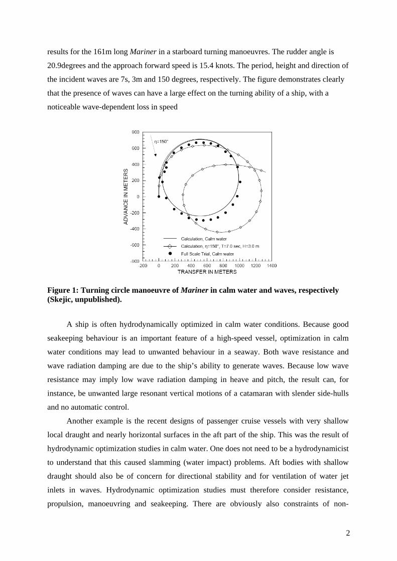
results for the 161m long Mariner in a starboard turning manoeuvres. The rudder angle is
20.9degrees and the approach forward speed is 15.4 knots. The period, height and direction of
the incident waves are 7s, 3m and 150 degrees, respectively. The figure demonstrates clearly
that the presence of waves can have a large effect on the turning ability of a ship, with a
noticeable wave-dependent loss in speed
Figure 1: Turning circle manoeuvre of Mariner in calm water and waves, respectively (Skejic, unpublished).
A ship is often hydrodynamically optimized in calm water conditions. Because good
seakeeping behaviour is an important feature of a high-speed vessel, optimization in calm
water conditions may lead to unwanted behaviour in a seaway. Both wave resistance and
wave radiation damping are due to the ship’s ability to generate waves. Because low wave
resistance may imply low wave radiation damping in heave and pitch, the result can, for
instance, be unwanted large resonant vertical motions of a catamaran with slender side-hulls
and no automatic control.
Another example is the recent designs of passenger cruise vessels with very shallow
local draught and nearly horizontal surfaces in the aft part of the ship. This was the result of
hydrodynamic optimization studies in calm water. One does not need to be a hydrodynamicist
to understand that this caused slamming (water impact) problems. Aft bodies with shallow
draught should also be of concern for directional stability and for ventilation of water jet
inlets in waves. Hydrodynamic optimization studies must therefore consider resistance,
propulsion, manoeuvring and seakeeping. There are obviously also constraints of non-
3
hydrodynamic character. For instance, minimizing ship motions may lead to higher global
structural loads.
Several of our examples in the main text deal with ship applications and we will in
particular focus on violent fluid motions and hydrodynamics of high-speed vessels. The future
increased role of computer simulations relative to experiments is also addressed.
Examples on marine structures that are left out of the detailed discussions are fish farms
and fishing nets. Increased knowledge about the flow through fishing nets in current and
waves with due consideration of the net deformation is important, for instance, for the design
of mooring systems of fish farms. Vortex induced vibrations is a challenging problem, for
instance, for the design of pipelines. The towing of flexible long seismic cables is difficult to
theoretically predict under dynamic conditions due to limited knowledge about flow
separation at small angles of attack.
2. VIOLENT FLUID MOTION Examples on fluid motions that will be discussed are green water on deck, sloshing and
slamming. Capsizing of damaged ship with water ingress /egress in waves has similarities
both with sloshing in tanks and green water on deck. Sloshing in moon pools is another
example that could be mentioned. An important issue is to design efficient damping devices,
such as perforated walls in the pool. A similar resonance phenomenon occurs between two
adjacent ships in waves, or for a ship alongside a terminal. Conventional engineering tools
based on linear panel methods cannot accurately describe the flow.
2.1 Green water on deck There is extensive work worldwide in applying Computational Fluid Dynamics (CFD) to
green water on deck. However, most work is related to two-dimensional flow. An attempt has
been made by Greco et al. (2007) to classify how the different green water phenomena occur
as a function of wave parameters in head sea conditions for stationary ships with blunt bows,
based on experimental and theoretical studies of a restrained two-dimensional body. A
typical application is to a Floating Production Storage and Offloading (FPSO) vessel.
Interaction between the incident waves and the hull plays an important role. One type of green
water is the so called dam-breaking phenomenon, where a vertical wall of water is generated
at the edge of the deck due to the relative vertical motion between the ship and the waves. The
4
subsequent motion of the water resembles the breaking of a dam, water flooding at high speed
(15-20 m/s) along the deck. Its impact against deck structures and equipment can cause
serious damage.
A second scenario is water hitting the deck as a plunging breaker. Actually, the
plunging breaker may hit a deck house in the forward part of the ship. A third case is the
"hammer fist" effect of water on deck, using an analogy to karate. A large mass of water rises
above the deck and collapses heavily over a substantial area of the ship during a "hammer
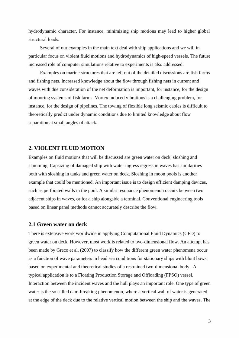
fist" type of water on deck. Figure 2 shows how these different phenomena occur as a
function of the incident wave steepness and the Ww/Wb-ratio. Here Ww is the maximum
vertical velocity of the incident waves and Wb is the maximum vertical fluid velocity at the
ship's bow.
Fig. 2: The effect of green water on deck as a function of the incident wave steepness and Ww/Wb-ratio. Ww is the maximum vertical incoming wave velocity and Wb is the maximum relative fluid velocity at the bow. Wave-body interaction plays a similar decisive role in bow stem slamming as in the green-
water situation.
2.2 Sloshing Sloshing in a partially filled container is a violent resonant free surface flow with
strongly nonlinear behaviour. Sloshing must be considered for almost any moving vehicle or
structure containing a fluid with a free surface.
A partially filled ship tank will experience violent fluid motion when the ship motions
contain energy in the vicinity of the highest natural period for the liquid motion inside the
5
tank. Impact between the liquid and the tank roof is then likely to occur for larger filling
ratios. The consequence is wave breaking, spray and mixing of gas and liquid. Actually,
extreme cases with gas bubbles everywhere in the liquid have been experimentally observed.
Because sloshing is a typical resonance phenomenon, it is not necessarily the most
extreme ship motions or external wave loads that cause the most severe sloshing. This implies
that external wave induced loads can in many practical cases be described by linear theory.
However, nonlinearities must be accounted for in the tank liquid motions. Because it is the
highest sloshing period (natural period) that is of prime interest, vertical tank excitation is of
secondary importance. Lateral and angular tank motions cause the largest liquid response in
the frequency range of interest. An increased tank size increases the highest natural period of
the liquid flow. As a consequence, higher sea states and larger ship motions excite sloshing
around resonance. The less internal structures obstructing the flow in the tank are present, the
more severe sloshing is.
There is a variety of ship tank shapes. This includes rectangular, prismatic, tapered and
spherical tanks as well as horizontal cylindrical tanks. The fluid may be oil, liquefied gas,
water or heavy density cargoes like molasses and caustic soda. Ideally one should be able to
predict two phase flow due to strong mixing of gas with the liquid. However, it is hard enough
to predict one phase flow.
Sloshing has always been an important design criterion for oil tankers, even though
partial filling is rare in actual operation. Environmental concerns have led to requirements
about double hull tankers. Ship owners try to avoid internal structures in cargo tanks for
cleaning reasons. The resulting wide and smooth oil tanks increase the probability of severe
sloshing. Sloshing is also of concern for FPSO units and shuttle tankers. The severity of
sloshing is connected to possible filling height restrictions for oil tankers, gas carriers, shuttle
tankers and FPSO units. Often, operators require no restrictions on filling heights to achieve
loading flexibility. Because ballast exchange is required outside the port for a bulk carrier,
there are possibilities for sloshing damages. Particularly, the hatch cover is vulnerable. Partial
fillings in LNG carriers are a consequence of gas boil-off during operation. Sloshing in tanks
has received increased attention due to the design of new types of prismatic LNG tanks. The
interior tank surface is relatively smooth.
The hydrodynamic loading inside a tank can be classified either as impact loads or
‘dynamic', non-impulsive, loads. In this context dynamic loads mean loads that have
dominant time variations on the time scale of the sloshing period, while impact loads may last
only from 310− to 210− seconds. It is the slamming pressures and resulting stresses in the

6
membrane structure that are of the main concern in the design of prismatic LNG tanks.
Sloshing loads are of significance for both fatigue and ultimate strength. Local structural
response due to liquid impact is an important response variable. Loads on possible internal
structures must be considered. Some internal structures, as a horizontal stringer on the wall or
web-frame at the tank roof, may be in and out of the liquid so that impact loads as well as
dynamic loads may matter. Hydroelastic effects are sometimes of importance for impact
loads. Total dynamic loads on the tank are of interest in order to estimate tank support
reactions as for instance for a spherical LNG tank and possible global interaction with ship
dynamics.
The ship motions excite sloshing, which in return affects the ship motions. Ships
equipped with anti-rolling tanks utilize this effect. The sloshing induced roll moment on the
vessel will cause roll damping by properly choosing the highest natural sloshing period close
to the roll natural period. FPSO units sometimes have several partially filled tanks during
operation. The wave induced motions and loads on these ships will then be influenced by the
dynamic motion of the liquid in the tanks. Because ship motions can strongly affect the mean
and slowly-varying wave drift forces and moments, sloshing may also matter in a station-
keeping analysis.
The tank shape, the level of filling and the characteristics of the tank motion, for
example amplitude and frequency content, make up the principal parameters that determine
the nature of the free surface flow. The relative importance of the different parameters
depends on the characteristics of the flow, i.e. the response. There is a clear difference
between sloshing in a shallow liquid condition and higher filling level conditions. For small
ratios between liquid depth and tank length and an excitation frequency around resonance, a
hydraulic jump or bore, which travels back and forth in the tank, is formed. When the steep
front of the bore hits the tank wall, an impact occurs and a thin vertical jet shoots upwards.
When the liquid depth is non-shallow and the liquid motion is two-dimensional, the free
surface motion resembles a standing wave. Swirling or rotational flow is a special feature of
three-dimensional flow, for instance, in a spherical tank, a vertical circular tank or a square-
based tank.
When the interior tank surface is smooth and there are no internal structures as
stringers obstructing the flow, the viscous damping of the resonant fluid motions is small as
long as wave breaking does not occur. The damping for a smooth tank can be very small at
finite depth, i.e. it takes a very long time for transience to die. The damping increases in
general with decreasing liquid depth. Large amplification of the liquid motion occurs in a
7
resonant condition. This leads to important nonlinear liquid behaviour inside the tank
associated with nonlinear transfer of energy between different modes of liquid motion.
Secondary resonances may matter. This means that higher harmonic oscillations caused by
nonlinearities excite resonance periods lower than the primary resonance period(s). Secondary
resonance increases in importance with decreasing liquid depth and increasing excitation
amplitude.
It is popular to use Computational Fluid Dynamics (CFD) to model sloshing. We will
address this approach in a more general way later in a separate section. However, the
analytically based multimodal modal time domain method presented by for instance Faltinsen
& Timokha (2001) and Faltinsen et al. (2005) is more suitable to understand the many
different flow configurations that can occur during sloshing. The assumptions are potential
flow, no overturning waves and infinite tank roof height. The tank wall surface must be
vertical in the free surface zone. The method is extremely fast from a computational point of
view. The method has been derived for two-dimensional flow in rectangular tanks and for
three-dimensional flow in prismatic tanks with a rectangular base. The effect of small chamfer
at the tank bottom has been studied in a two-dimensional case. The method has been
extensively validated by experimental results for wave elevation, lateral force and roll
moment. The 2D studies have examined how the flow changes physical character by going
from finite through intermediate to shallow liquid depth. The excitation amplitude is also an
important parameter. The physical dissipation increases with decreasing depth.
The steady-state solutions may have several branches. Some of the branches may be
unstable. We cannot have steady-state solutions along an unstable branch. Jumps can happen
between different branches of solutions.
The multimodal method has been applied to three-dimensional flow with a square-
based tank. There are three types of possible dominant steady-state wave response for
longitudinal harmonic excitation, namely, ‘planar’ (two-dimensional), ‘swirling’ (rotary
motions) and so-called ‘squares’-like three-dimensional steady-state waves formed by a
combination of diagonal wave patterns. Even with longitudinal excitation along a tank wall,
3D waves will occur due to non-linear interaction in a nearly square-based tank.
By adopting a stability analysis scheme, one can calculate effective frequency
domains for the different wave behaviour and find critical depths where either the frequency
domains of stable regimes or their wave response may change dramatically. Frequency
domains with no steady-state solutions, i.e. “chaos” exist. This has been experimentally
confirmed and gives important guidance for CFD calculations.

8
Both prismatic and spherical tanks are commonly used on LNG carriers. The most
important load on a spherical tank is the sloshing-induced hydrodynamic force, the
predominant component of which is the lateral force. Swirling occurs readily so there is in
general a force component perpendicular to the forced oscillation direction.
2.3 Slamming Slamming is of concern in many marine applications. Slamming on ships is often categorized
as bottom, bow-flare, bow-stem and wetdeck slamming. Wetdeck slamming has similarities
with other nearly horizontal parts of a ship such as large overhanging sterns. Green-water
impact on deck structures and bow-stem slamming are of concern for FPSO units. Slamming
is important in the design of a ship tank. There are similarities between slamming on ships
and offshore platforms. Breaking waves can impact on a ship hull or the columns of a
platform. Run-up along the columns can cause local damage of the platform deck. A platform
is normally designed with an air gap to avoid global water impact. However, slamming may
happen due to unanticipated large waves (Figure 3) or due to the subsidence of the sea floor
for bottom-mounted platforms. Bottom slamming should be considered on shallow-draft
barge-type Very Large Floating Structures (VLFS) proposed as floating airports in the coastal
zone. Examples on more special types of water impacts are slamming on air bags of Surface
Effect Ships (SES), drop of mines, accidental drops of pipes from platforms and analysis of
free-fall life boats. The deceleration, slamming loads and hydrodynamic loads on the top
cover of the life boat may matter. This issue has lately got increased attention for life-boats on
platforms in the North Sea. A too low maximum operating sea state can have serious
economic consequences due to stop in oil and gas production.
Figure 3: Wetdeck slamming on a semi-submersible platform and artist’s impression of bow slamming causing global elastic vibrations (whipping) of the ship hull. Slamming in a ship tank is associated with violent liquid motion and many possible
impact situations have to be considered. For instance, large filling ratios can cause important

9
slamming loads. Examples are high curvature free surface impact and impact with an
oscillating gas cavity. Another possible scenario is a sudden flip-through of the free surface at
the tank wall. A liquid wedge with a high velocity will as a consequence impact on the tank
roof. A chamfered tank roof is likely to reduce the severity of slamming.
Steep waves impacting on a vertical tank wall represents an important consideration
for shallow and intermediate liquid depths of a tank. An example is hydraulic jumps that can
be formed at resonant conditions for shallow liquid conditions.
It is common to analyze slamming in a tank by assuming a two-dimensional flow.
However, swirling may cause important impact against the tank roof corners for non-small
liquid depths in a nearly square-based tank.
Both local and global slamming effects must be considered. This is illustrated in the
case of bow slamming on a ship in Figure 3 where the resulting global elastic vibrations
(whipping) of the ship are exaggerated. The local slamming analysis is typically done by first
calculating the ship motions without impact and then consider the impact with given
conditions for the impacting hull. However, this procedure does not account for the mutual
interaction between slamming and the global ship behaviour and needs to be improved in the
future.
Many physical effects may have to be considered such as gas cushions, liquid
compressibility and hydroelasticity. When analyzing slamming, one must always have the
structural reaction in mind. An important consideration is the time scale of a particular
hydrodynamic effect relative to wet natural periods for structural modes contributing
significantly to large structural stresses. If the time scale of a hydrodynamic effect is very
small relative to important structural natural periods, the hydrodynamic effect can be
neglected. When the hydrodynamic loads occur on a time scale of important structural
periods, hydroelasticity must be considered. This implies that the fluid (liquid, gas) flow must
be solved simultaneously with the dynamic elastic structural reaction.
Local external slamming effects on ship structures of steel and aluminum are first
discussed. Drop tests with horizontal plates with correctly scaled elastic properties of steel
and aluminum on calm water as well as varying wave conditions and impact conditions have
shown recorded maximum pressures with very large variations for a given drop speed. A
maximum pressure of about 80 bar was recorded with a drop speed of 6 m/s. However, the
recorded strains were not sensitive at all and showed a time variations dominated by the
lowest beam mode. The maximum strain occurred approximately one quarter of the highest
natural period after the impact. The effect of the impact was to cause a force impulse to the

10
plate. The very high slamming pressures are unimportant, i.e. they cannot be used as a static
loading and there is no correlation between pressures and strains. Numerical simulations of
water entry of wedge- formed ship cross-sections with stiffened plating have shown the
importance of the ratio between the loading (wetting) time and the highest natural period for
the structure. If these results are translated into realistic ship structural dimensions and
relative vertical motions between the ship and the waves, a rough guidance is that local
hydroelasticity should be considered when the angle between the impacting free surface and
the hull surface is less than 5 degrees.
We then consider global slamming effects and choose wet deck slamming on a
catamaran in head sea as an example. Because of the very different time scales of local and
global structural vibrations, we can consider the local structure of the wetdeck as rigid in the
global analysis. Heave, pitch and two-node longitudinal bending are important modes of the
ship. Because the duration of the impact and the water exit (decrease of wetted surface) is
smaller than one quarter of the natural period of heave and pitch, the force impulse becomes
important. This enables us to simplify the analysis. Both water entry and exit must be
considered. Nonlinear hydrostatic and Froude-Kriloff loads matter. Studies have shown that
the Wagner method is unnecessary. Further, only the added mass force is needed during water
exit.
Slamming in ship tanks will now be focused on. The discussion has also relevance for
slamming in other applications. It is common in tank design to do model tests for sloshing
induced slamming effects by means of forced oscillation tests. However, the scaling of the
model test results represents a challenge due to the many physical effects that may matter.
Because sloshing is associated with gravity waves, we must require the Froude
number is the same in model and full scale. Further, the wave induced ship motions that
excite sloshing, is also Froude scaled. If harmonically forced oscillation of the tank with
frequency σ is considered, Froude scaling implies that /L gσ must be the same in model
and full scale. Here L is a characteristic tank dimension such as the tank breadth. A
conventional model test approach does only consider the effect of Froude scaling. However,
other scaling parameters of possible importance are summarized below.
If hydroelasticity matters during impact, we must ensure that the relevant natural
frequencies for the elastic structural vibrations are Froude scaled. For instance, let us consider
a steel tank. The bending stiffness matters for the natural elastic frequencies of importance.
Further, the length of the elastic plate must be geometrically similar in model and full scale.

11
The scaling of the natural frequency may be achieved by having different bending stiffness EI
in model and full scale. The bending stiffness may be properly scaled by considering a
different material and/or changing properly the thickness of the material. Because the main
interest is to find the slamming induced structural stresses, care must also be shown in scaling
structural stresses. More structural modes may be needed for membrane structures than for
steel structures. Some of the important structural modes for membrane structures may have
relatively lower natural periods than for steel structures.
If slamming is associated with the formation of gas pockets, the Euler number must be
the same in model and full scale. The Euler number is defined as 2/aEu p Uρ= . Here ap is
the ullage pressure, i.e., pressure in the ambient gas of the tank. The consequence of both
Froude and Euler number scaling is that the ratio between ap in model and full scale is equal
to the ratio between the length scale L in model and full scale.
A gas pocket has a natural frequency associated with the compressibility of the gas
and a generalized added mass due to the liquid oscillations caused by the gas cavity
oscillations. If only Froude scaling is used, it has been shown that Froude scaling is
conservative. Further, even though the gas cavity oscillations may be linear in model scale
they may be strongly nonlinear in full scale with a time history that can cause larger
hydroelastic effects.
Because LNG is boiling, the cavitation number is a factor. The cavitation number is
defined as 2( )/(0.5 )a vp p Uσ ρ= − where vp is the vapor pressure. There is strongly limited
knowledge about the effect of boiling on the slamming loads in an LNG tank.
The Cauchy number 2 /a vC U Eρ= characterizes the effect of compressibility on the
flow. Here vE is the bulk modulus for elasticity. The effect of liquid compressibility is less
important in the case of a liquid with no gas bubbles and may be disregarded for a steel tank.
This is a matter of what are the important wet structural natural periods. However, the speed
of sound in a liquid can be substantially lower in the case of a mixture of gas and liquid. The
consequence is an increased characteristic time scale for the effect of liquid compressibility.
Because a mixture of gas and liquid can happen during violent sloshing and because LNG is
boiling, we cannot out rule the effect of compressibility on slamming loads. The mixture of
LNG and gas is not homogeneous. It is only the upper layer of LNG that is boiling. Because
the sloshing and the impact affect the pressure distribution in the fluid and the pressure
determines if cavitation occurs, the amount of bubbles is time dependent. The void fraction
12
is therefore a function of time and space. This is an area requiring future research. Surface
tension and viscosity are believed to be less important effects during slamming.
.
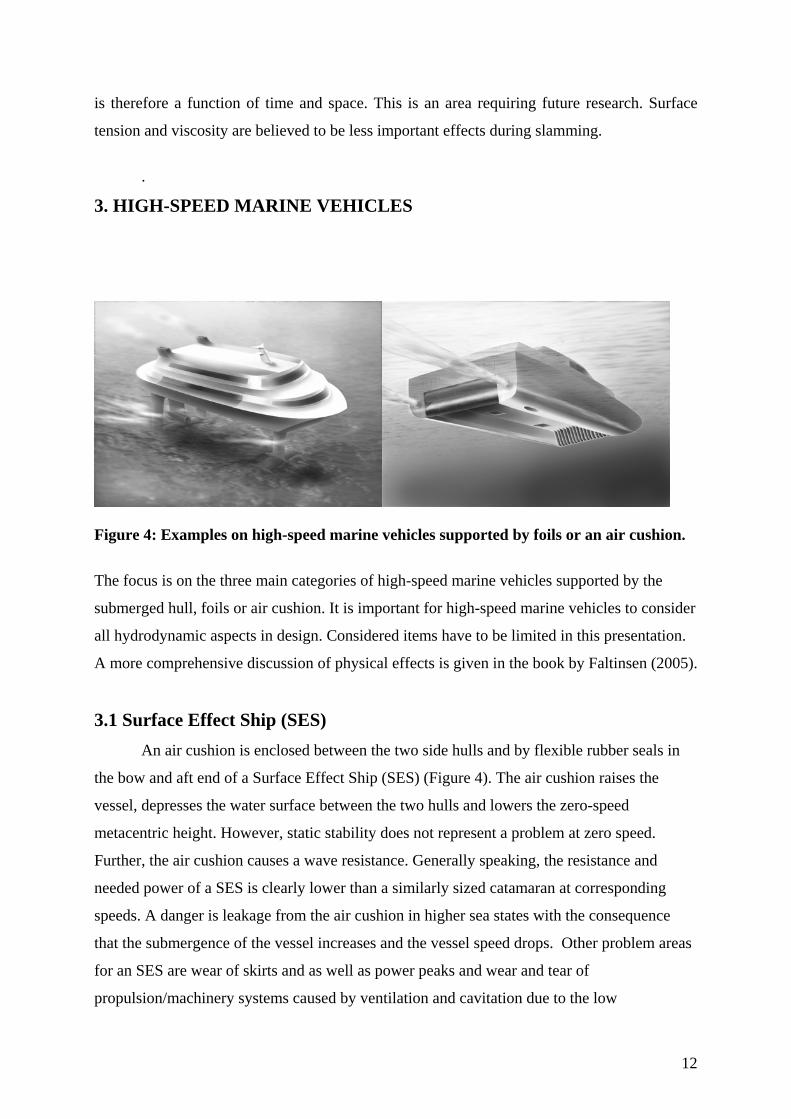
3. HIGH-SPEED MARINE VEHICLES
Figure 4: Examples on high-speed marine vehicles supported by foils or an air cushion. The focus is on the three main categories of high-speed marine vehicles supported by the
submerged hull, foils or air cushion. It is important for high-speed marine vehicles to consider
all hydrodynamic aspects in design. Considered items have to be limited in this presentation.
A more comprehensive discussion of physical effects is given in the book by Faltinsen (2005).
3.1 Surface Effect Ship (SES) An air cushion is enclosed between the two side hulls and by flexible rubber seals in
the bow and aft end of a Surface Effect Ship (SES) (Figure 4). The air cushion raises the
vessel, depresses the water surface between the two hulls and lowers the zero-speed
metacentric height. However, static stability does not represent a problem at zero speed.
Further, the air cushion causes a wave resistance. Generally speaking, the resistance and
needed power of a SES is clearly lower than a similarly sized catamaran at corresponding
speeds. A danger is leakage from the air cushion in higher sea states with the consequence
that the submergence of the vessel increases and the vessel speed drops. Other problem areas
for an SES are wear of skirts and as well as power peaks and wear and tear of
propulsion/machinery systems caused by ventilation and cavitation due to the low

13
submergence of the water jet inlet. The latter effect is most probable to happen in a seaway or
during a turning manoeuvre. Wetdeck slamming and bow diving may occur. Further, berthing
of an SES at high wind speeds may be difficult.
Cobblestone oscillations cause unpleasant vertical accelerations in small sea states and
are the result of resonant compressible flow effects in the air cushion. It is called cobblestone
oscillations to make the resemblance to driving a car on roughly laid cobblestones.
Compressibility effects of the air in the cushion are essential. The oscillations are excited
because the waves change the enclosed air cushion volume. It is the vertical vessel
accelerations that are of concern. When cobblestone oscillations are not excited, i.e. for higher
sea states, an SES will in general have good seakeeping behaviour relative to a similarly sized
catamaran.
Figure 5: Physical effects influencing cobblestone oscillations of an SES (Ulstein, 1995).
Figure 5 gives an overview of the physical effects that matter in describing the
cobblestone oscillations (Ulstein, 1995). The 1-D wave equation referred to in the figure
means that spatially varying one-dimensional standing acoustic waves and spatially uniform
dynamic air cushion pressures are studied. Representative values for a 30 m long SES of the
spatially uniform pressure resonance frequency and the one node longitudinal acoustic
resonance frequency are 2Hz and 5Hz, respectively. There are effects of the dynamic pressure
in the air bag and the fact that the water waves impact on the bag and elastic vibrations of the
bag. The vibrations of the bag are like a wave maker for the acoustic wave motions in the air
cushion. The figure also mentions spatially varying air pressure in the vicinity of the air bag.
Because this occurs on a length scale that is short relative to the important acoustic
wavelength, it can be analyzed by assuming incompressible fluid. Due to continuity of fluid

14
mass, the escaping air flow under the air bag must have a mean velocity that is dependent on
the local height between the air bag and the water surface. Because high velocity implies
small pressure, the escaping air flow causes a suction force on the air bag. This influences the
mean escape area of the air from the air cushion. The leakage and inflow to the air cushion
influences the damping level of the cobblestone oscillations.
In reality one would use an automatic control system to damp out some of the
"cobblestone" effect. This is done by controlling the air flow out from the cushion in such a
way that it effectively acts as a damping on the system. In order to do that properly one needs
a simplified but rational mathematical method that accounts for the dynamic pressure
variations in the air cushion in combination with the global heave and pitch accelerations of
the vessel. Sørensen (1993) used a louver system consisting of two vent valves at the deck in
the front of the air cushion. The opening and closing of the vent valves control the air flow
from the air cushion so that one gets a damping effect on the system. The placement of the
louver system is essential. For instance, if the louver system is placed at midships, it will have
a negligible effect on the acoustic resonance mentioned above. The reason is simply that the
acoustic pressure component has a node, i.e. no amplitude, at midships, while it has its
maximum amplitude at the ends of the cushion.
Both the Euler and Froude numbers matter for cobblestone oscillations. A
depressurized tank with a wave maker generating high quality waves with small wave lengths
is needed. Simplified numerical methods accounting for automatic control are commonly used
instead of model tests.
3.2 Hydrofoil vessels . A hydrofoil vessel with a fully-submerged foil system is illustrated in Figure 4. It has
in foilborne conditions in general good seakeeping characteristics, create small wash and have
small speed loss due to incident waves. Foils are normally designed for subcavitating
conditions. However, the possibility of cavitation is then an important issue. Our discussion
assumes subcavitating foils.
The designer tries to maximize the foil’s lift-to-drag ratio and the speed for cavitation
inception. Further, the weight of the strut-foil system must be minimized with due
consideration of structural strength.
Relevant structural loads are slamming, hull bending moments in foilborne condition
and bending of the forward foil and strut during recovery from a forward foil broach.

15
Slamming on the side hulls of a hydrofoil catamaran is not considered as a problem. The
reason is large deadrise angles. Because a monohull hydrofoil vessel uses typically a planing
hull with relatively small deadrise angles, slamming loads matter. If a hydrofoil catamaran is
hullborne in bad weather, wetdeck slamming must be considered. The possibility of
grounding and hitting of objects like logs against the strut-foil system must also be evaluated.
Flutter of foils and struts could cause catastrophic failure, but this has never occurred
yet. The classical flutter scenario is dynamic instability of combined bending-torsion
vibrations of a strut-foil system. The mass ratio, i.e. the ratio of a typical density of structural
material to the density of the fluid is an important parameter. This difference creates a clear
advantage for a hydrofoil vessel relative to an aircraft when it comes to flutter.
A surface-piercing hydrofoil system in foilborne condition stabilizes the vessel in
heave, roll and pitch. This can be understood by means of a quasi-steady analysis. Consider
for instance that the heave motion increases. Here heave is positive upwards. This causes the
reduction of the wetted foil area. Because the lift is proportional to the wetted area, the lift due
to the foils decreases. The weight of the vessel balances the lift in the equilibrium position.
The increased heave implies that the vessel weight will force the vessel downwards. Another
way of saying this is that there is a restoring force in heave bringing the vessel back to the
equilibrium position. Similar static analysis can be made for heel and trim
A hydrofoil vessel with a fully-submerged foil system needs automatic control to
stabilize the vessel in heave, pitch and roll. Platforming and contouring modes are used in
connection with an active control system. The contouring mode is used in longer waves to
minimize relative vertical motion between the vessel and the waves and to avoid ventilation
and broaching of the foils. The platform mode is used to minimize vertical accelerations of
the vessel in relatively short waves.
The Reynolds number scaling of foil tests and how to ensure turbulent boundary layers
during model tests is an important issue. One effective way is to use Hama strips. The basis of
a Hama strip is a tape. A saw-tooth shape is made on the upstream edge by means of a scissor.
Cavitation on foils designed for subcavitating conditions limits the vessel speed to the
order of 50 knots. Cavitation appears when the pressure in the water is equal to the vapour
pressure, i.e. close to zero. The pressure distribution along the foil should be relatively flat in
order to minimize the possibility of cavitation, i.e. there must not be pronounced local
pressure minima (suction peaks). The consequence of cavitation is that the material of the foil
can be quickly destroyed and the lift capabilities of the foils can be significantly reduced.
Another consequence is that the drag on the foils increases. Because cavitation is

16
accompanied by noise generation, one can hear on board the vessel when there is the
possibility of damage due to cavitation. If the vessel speed should be increased substantially
beyond 50 knots, supercavitating foils must be used to avoid cavitation damage. They are
characterized by much lower lift-to-drag ratios and lift coefficients than subcavitating foils.
The importance of cavitation and ventilation for hydrofoil vessels will be illustrated
by model test results for the side force coefficient of a strut used as a rudder on a hydrofoil
catamaran. Ventilation means that air enters from the atmosphere to low pressure areas on the
strut. It occurs typically at angles of attack ψ higher than 4° to 6° for a strut on a hydrofoil
vessel in foilborne condition. However, this depends on the Froude number. Ventilation will
cause a significant drop in the force. Hysteresis is associated with ventilation. This means that
ψ may have to be lowered significantly to restore non-ventilated conditions. The detailed
physical understanding of ventilation is limited.
Figure 6: Model test results of the side force coefficient LC of a front strut-foil system used as rudder on a hydrofoil catamaran (Minsaas, unpublished).
Figure 6 shows model test results for a front strut-foil system used as a rudder on a
hydrofoil catamaran. The model tests were done in the depressurized circulating free surface
tank at the Technical University of Berlin. The side force coefficient LC is presented as a
function of the yaw angle ψ both at atmospheric air condition and at the cavitation number

17
0 349.σ = corresponding to the full-scale condition. The pitch angle is 2.7° and the
submergence Froude number hFn is 5.96 corresponding to a full-scale speed of 50 knots. The
drop in the absolute value of LC with either increasing positive ψ -values or decreasing
negative ψ -values is an indication of the start of ventilation. This occurs, for instance, at
4ψ °∼ when 0 349.σ = and at 6ψ = ° at atmospheric air condition.
A consequence of the ventilation at the strut is that air penetrates to the foil and causes
a significant drop in the lift force on the foil. This drop occurred at ψ approximately equal
to 6± ° . The lift force on the ventilated foil was the order of 50% of the non-ventilated lift.
3.3 Semi-displacement and planing vessels. Semi-displacement vessels without damping systems may have unsatisfactory seakeeping
behaviour. One reason is that the excitation loads in heave and pitch at resonance condition in
head sea increases with forward speed. Increased heave and pitch damping of semi-
displacement vessels is commonly achieved by using T-foils in the bow (Figure 7). Because
ventilation and cavitation may limit the operability in higher sea states, wrong conclusions
about seaworthiness can result from conventional towing tank tests. While the wave-induced
response of displacement vessels can normally be adequately described by linear theory, this
is not true for planing vessels. A linear 2.5D (2D+t) theory based on potential flow theory has
become popular in describing wave resistance and wave induced motions and loads on semi-
displacement vessels.
Figure 7: T-foil placed below the keel and used to damp vertical wave-induced ship motions at high speed (SEASTATE).
The steady wave pattern (wash) associated with fast semi-displacement vessels are of
concern in coastal and inland waters. The wash may cause nearby small boats to capsize or
ground or large moored ships to move and mooring lines to break. The waves may cause
erosion or even collapse of a bank. When the waves approach a beach, the amplitudes

18
increase and the waves break. This may happen when the ship is out of sight, surprise
swimmers, and represent a risk factor.
An example of the measured wave elevation in the near aft of a trimaran in deep water
is shown in Figure 8. Free surface nonlinearities due to flow separation at the transom stern
and breaking waves matter. Numerical methods have clear limitations in describing the wave
field.
Figure 8: Model tests on high-speed trimaran in calm water. Wave elevation measurements at Froude number 0.4, and colour code for the ratio / Lη between the wave elevation and the ship length (INSEAN).
The water depth can have an important influence on the wave pattern when the water
depth-to-ship length ratio h/L is small. An important parameter is then the depth Froude
number /hFn U hg= where U is the ship speed. 1hFn = corresponds to the critical
speed. Large changes occur at the critical depth Froude number. The ship waves are very
different for subcritical, critical and supercritical speeds in shallow water. The wave pattern at
subcritical speed consists of transverse and divergent waves while only divergent waves exist
for supercritical speed. The supercritical waves have a very small decay with distance which
makes them of particular concern from a wash point of view. The angle (Kelvin angle)
between the boundary of the wave system and the ship course is 19 28′ in deep water and
when 0.5 0.6hFn < − . A rapid increase in the Kelvin angle occurs for 0.9hFn > , and the
angle is 90 for 1hFn = . False wall effects can therefore occur during shallow water model
tests around the critical Froude number. If the vessel is in the vicinity of critical speed and in a
channel, large waves can build up, be unsteady relative to the ship and travel faster than the
ship. Russel described in 1865 that one day, the happiest of his life, something unexpected

19
happened during his towing tests. A large solitary wave occurred ahead of the ship. He could
not follow it by foot and got on the horseback and followed it for more than a mile.
Dynamic instability has increased importance with increasing Froude number. One
reason is the increased importance of hydrodynamic pressure relative to hydrostatic pressure
with increasing forward speed. There is a broad variety of dynamic stability problems. The
loss of steady restoring moment in heel with forward speed can cause a sudden list of a round
bilge monohull to one side. This can at high speed be followed by a violent yaw to one side.
The consequence can be capsizing. This “calm water broaching” is the main reason round-
bilge hulls should not operate beyond a Froude number of 1.2 (Lavis, 1980). The loss of
steady restoring heel moment with speed should be accounted for in the design by having
sufficiently high metacentric height at zero speed.
When a high-speed catamaran in following waves has a speed close to the phase speed
of the incident waves, the catamaran can come in a position relative to the waves so that the
fore part of the vessel dives into a wave crest. If there is not sufficient buoyancy in the fore
part of the vessel, a critical situation may occur.
Examples of dynamic instabilities for planing vessels are “corkscrew” pitch-yaw-roll
oscillations, chine walking and porpoising. Porpoising is dynamic instabilities in the vertical
plane and is commonly seen. Cavitation and ventilation in the aft body can cause dynamic
instabilities.
The Froude number dependence and roll, sinkage and trim matter for manoeuvring of
semi-displacement vessels. Strong nonlinearities may occur for a trimaran. For instance,
steady heel may cause sign change in steady yaw moment for relatively small heel angles.
Numerical methods have difficulties in describing those effects.
Global wave loads matter in the design of vessels longer than 50m. Important global
loads for catamarans are transverse vertical bending moment (often called split moment),
vertical shear force and pitch connecting moment, as illustrated in Figure 9. Torsional
moments, vertical shear forces and vertical bending moments at transverse cross-sections are
also of concern, as for monohulls. Both continuous wave loading and slamming will cause
global loads. When wetdeck slamming-induced global loads are analyzed, the vessel must be
considered elastic. The response is called whipping. When we consider the effect of
continuous wave action, the catamaran is often considered as rigid in the determination of the
global loads. However, it should be ensured in a linear analysis that the natural frequencies of
the global elastic modes are higher than the encounter frequencies of practical interest. When

20
the global elastic modes are accounted for during continuous wave loading, the phenomenon
is called springing. Nonlinear effects may also cause springing.
Figure 9: Examples on global wave loads on a catamaran. The largest global wave loads in a longitudinal cut of a catamaran occur in oblique sea
conditions. The time window for testing in existing model tank facilities in oblique sea can be
limited due to the high speed and the fact that transients must die out. Experimental error
sources associated with non-constant wave conditions in a basin should also be considered.
4. COMPUTATIONAL FLUID DYNAMICS It has become popular to use Computational Fluid Dynamics (CFD) to solve fluid flow. There
is a broad variety of numerical methods. An overview is given in Figure 10. By CFD we mean
that the fundamental governing equations, with initial conditions and nonlinear boundary
conditions based on either potential flow, inviscid or viscid fluids are solved. For instance, we
do not mean linear strip theories for ship motions.

21
Figure 10: Overview of numerical methods in fluid dynamics with emphasis on possible solution strategies within Navier-Stokes solvers (Greco, unpublished). We may ask: What are then the advantages and disadvantages of using CFD?
Advantages are that complex structures and general excitation may in principle be considered.
A CFD method may provide good flow visualization including details such as the vorticity
distribution. Flow separation around structures can be simulated. It seems generally accepted
that CFD codes have difficulties in predicting impact loads when the angle between the
impacting free surface and the body surface is small. Actually hydroelasticity may then play
an important role. Most computations do not consider this fact and assume a rigid structure.
Another disadvantage is that the CFD methods are time consuming which makes
statistical estimates of response variables in a stochastic sea difficult. Some methods may not
be robust enough. For instance, a Boundary Element Method breaks down when an
overturning wave hits the underlying free surface. Numerical problems may also arise with a
BEM at the intersection between the free surface and the body boundary. When a BEM

22
works, it is in general a fast and accurate method relative to other CFD methods. Nonlinear
effects associated with water entry of two-dimensional bodies can in many cases be
adequately described by potential flow theory and the Boundary Element Method.
CFD methods based on the Navier-Stokes equations are often very robust. Movies
based on CFD may look convincing without always representing the reality. Care must be
shown that the solutions are true physical solutions. If sufficient care is not shown, some of
the methods may numerically lose or generate liquid mass on a long time scale. This is of
particular concern in sloshing simulations. Because the highest natural period of the liquid
motion is strongly dependent on the liquid mass, this can result in an unphysical numerical
simulation. Verification and validation are a must. By verification is meant that the solutions
are consistent with the governing equations, initial and boundary conditions that have been
used. By validation is meant comparisons with model tests and full scale trials. Experiments
are, of course, not free of errors. So it is important that the experiments are accompanied by
an error analysis. Verification can be done by temporal and spatial convergence tests and by
controlling that conservation of global mass, momentum and energy are satisfied.
Comparisons should be made with analytical methods such as the linear potential flow theory.
Because commercial CFD codes are generic of nature and special physical features are
specific for the different application fields, one cannot necessarily trust documentation of
verification and validation in other applications than those one is interested in.
If a step should be made in improving seakeeping calculations, we have to rely on
Computational Fluid Dynamics (CFD) and solve the Navier-Stokes equations. A graph was
made by the author in 1988. Major previous achievements in computations of wave induced
motions and loads were listed as a function of available computer power and year. A
prognosis of the computer power in year 2000 was made and it was asked if it would be
common to solve the 3D Navier Stokes equations in waves for ships and ocean structures.
Even though the available computer power was underestimated, we are still not at the stage
where solving the Navier Stokes equations in waves is standard practice.
A domain decomposition method is suggested for strongly nonlinear flow at the ship.
The violent flow near the ship including possible green water on the deck and water impact is
handled by a CFD solver based on Navier-Stokes equation with two-phase flow while the
more moderate free surface motion at the rest of the sea is solved by a Boundary Element
Method. The following example assumes the near-field solver to be a Finite Difference
Method combined with a Level Set-method to describe the interface between water and air.
Computational time is roughly estimated by Greco (unpublished) to be 16 hours for one wave

23
period with a PC Pentium IV 2.8 GHz. If 1080 oscillation periods is assumed in a 3 hour
storm, this means a computational time of approximately two years. Further, many
realizations of each sea state as well as many sea conditions are needed in the design analysis.
Computational speed may not be an obstacle with the combined use of supercomputers, future
improvements in numerical methods and alternative design procedures by selecting time
windows with extreme conditions. However, we have still not solved all physical problems
needed for design such as ventilation, air cushions and proper turbulence modelling.
5. CONCLUSIONS There is an increased focus on Computational Fluid Dynamics (CFD). A broad variety of
numerical methods exist and it is difficult to favour one particular method to solve all marine
hydrodynamic problems. A straightforward application of CFD in solving the behaviour of
ship and ocean structures in severe weather is not conceivable in the near future if proper
response statistics should be derived. CFD for high-speed vessels is, in general, not ready for
design applications.
Simplified numerical methods based on rational physical approximations should be
further developed. An example is on describing cobblestone oscillations of an SES.
A balance between analytical methods, CFD, model tests and sea tests is
recommended. Further, links between the different disciplines of hydrodynamics as well as
other topics such as structural mechanics and automatic control have been stressed.
Research on violent fluid motions such as slamming, green water on deck, sloshing in
tanks, damaged ship with ingress/egress of water are important future activities. Knowledge
about the effect of boiling on slamming loads in a LNG tank is needed. A physical
understanding of what flow parameters matter for response variables of importance in design
and operation is essential. The time scale of a particular physical effect in order for the
structure to react, for instance in terms of maximum stresses, is a basis for deciding what
physical effects matter.
Dynamic instability, ventilation and cavitation are limiting factors for operation of
high-speed vessels. There is limited knowledge about ventilation. A depressurized towing
tank with wave maker and 6DOF forced oscillator is desirable. Large horizontal tank
dimensions may be needed for seakeeping and manoeuvring tests of high-speed marine
vessels.

24
6. REFERENCES Faltinsen, O. M., 2005. Hydrodynamics of High-Speed Marine Vehicles, Cambridge University Press. Faltinsen, O. M., Timokha, A. N. , 2001, Adaptive multimodal approach to nonlinear sloshing in a rectangular tank. J. Fluid Mech., Vol. 432, pp. 167-200. . Faltinsen, O. M., Rognebakke, O.F., Timokha, A. N., 2005. Resonant three-dimensional nonlinear sloshing in a square base basin, II: Effect of higher modes. J. Fluid Mech., 523, pp. 199-218. Greco M., Colicchio G., Faltinsen O.M., 2007. Shipping of water on a two-dimensional structure, Part II, in press, J. Fluid Mech. Lavis, D. R., 1980, The development of stability standards for dynamically supported craft, a progress report, Proc. of the High Speed Surface Craft Exhibition and Conference, pp. 384-394, Brighton, Sussex, UK: Kalerghi Publications. Sørensen, A., 1993. Modelling and control of SES dynamics in the vertical plane, Dr.Ing.
thesis, ITK-report 1993:7-W, Nor. Inst. Technol., Trondheim.
Ulstein, T., 1995. Nonlinear effects of a flexible stern seal bag by cobblestone oscillations of
an SES, Dr.Ing. thesis, Dept. of Marine Hydrodynamics, NTNU, Trondheim.

278 58(2007)3, 278-283
I. JURAGA, I. STOJANOVIĆ, T. NORŠIĆ ZAŠTITA BRODSKOGA TRUPA OD KOROZIJE I OBRAŠTANJAUDC 620.193/.197.6:629.5.024
Ivan JURAGA Ivan STOJANOVIĆ
Tihana NORŠIĆZaštita brodskoga trupa od korozije i obraštanja
Pregledni rad
Tehnološki korektno izvedena zaštita od korozije znatno utječe na produljenje životnog vijeka broda. Najraširenija tehnologija zaštite brodskoga trupa od korozije jest zaštita premazima, ali u obzir dolaze i koriste se i druge metode, npr. katodna zaštita. Fouling (engl. obraštanje) su kolonije biljnih i životinjskih morskih organizama na uronjenim površinama brodova, plutača, offshore i dru-gih potopljenih objekata koje izazivaju ozbiljne probleme: povećanje mase uronjene konstrukcije, povećanja otpora i smičnih naprezanja, anaerobnu koroziju kovnih površina. Kroz povijest su se pojavile nebrojene metode zaštite od obraštanja, a danas su u uporabi isključivo premazi koji se razvijaju u sve kvalitetnija (i okolišu ugodna) rješenja. U tehnologiji nanošenja AF premaza jednako su važni priprema površine, okolišni uvjeti i pravilno nanošenje kvalitetnoga premaza.
Ključne riječi: obraštanje, zaštita od korozije, zaštitni premazi
Protecting the Ship’s Hull Against Corrosion and FoulingReview paper
Corrosion protection if carried out technologically correctly, signifi cantly affects the extension of ship’s lifetime. The most widely used method for protecting steel is application of coatings, but other methods such as cathodic protection are also applied. Fouling is the settlement of animal and vegetable marine organisms on underwater surfaces of ships, buoys, offshore structures and other immersed objects which cause severe problems: increased weight of the structure, increased drag and shear stress, anaerobic corrosion of metal surfaces. The history records numerous meth-ods of fouling protection, but today coatings are applied exclusively (development of advanced, environment friendly coatings). Equally important in antifouling technology are surface preparation and climatic conditions as well as correct application of a high-quality coating.
Keywords: corrosion protection, fouling, protective coatings
Adresa autora (Authors’ address): Fakultet strojarstva i brodogradnje u Zagrebu, Ivana Lučića 5, 10000 Zagreb
Primljeno (Received): 2007-03-21Prihvaćeno (Accepted): 2007-04-23Otvoreno za raspravu (Open for discussion): 2008-09-30
1. Uvod
Brod kao složen i skup proizvod svoju funkciju mora obavljati tijekom životnog vijeka od nekoliko desetljeća, u uvjetima koji su s korozijskoga stajališta iznimno nepovoljni. Korozijska oštećenja mogu uzrokovati velike probleme na brodskoj konstrukciji, a s vremenom i kolaps konstrukcije što osim materijalne štete može uzrokovati ljudske žrtve, ekološke probleme i sl. Tehnički ispra-vno i pravodobno izvedena antikorozivna zaštita znatno utječe na produljenje životnog vijeka broda.
2. Zaštita brodskoga trupa od korozije
Najraširenija tehnologija zaštite brodskoga trupa od korozije jest zaštita premazima, ali u obzir dolaze i koriste se i druge metode. U brodogradnji se najčešće koriste zaštitni premazi iz grupe organskih prevlaka, dok je udio primjene svih ostalih tipova prevlaka bitno manji. Ovisno o dijelu konstrukcije koji se štiti, premazi imaju i druge namjene osim zaštitne (protuobraštajni, protuklizni, protupožarni itd.). Kod izvođenja zaštite od iznimne je važnosti odgovarajuće pripremiti podlogu, korektno nanositi premaz, te osigurati dobre radne uvjete (osvjetljenje, dostupnost površine, ventilacija) uz odgovarajuću mikroklimu (temperatura okolice, relativna vlažnost i sl.). Pravilan izbor metode bojenja
bitno utječe na cjelokupnu zaštitu površine (brzinu zaštićivanja i kakvoću izvedene operacije). Najčešće se koristi: bojenje četkom, valjcima, prskanje sa zrakom, bezračno i elektrostatsko prskanje [1].
Uz zaštitu premazima, važna je metoda zaštite od korozije u brodogradnji katodna zaštita. Postupak se temelji na privođenju elektrona kovini, bilo iz negativnoga pola istosmjerne struje (na-rinuta struja) bilo iz neplemenitije kovine (žrtvovana anoda), sve dok potencijal objekta ne padne ispod zaštitne vrijednosti jednake ravnotežnom potencijalu anode korozijskoga članka, čime nestaje afi nitet za koroziju, tj. kovina postaje imuna [1].
Inhibitore korozije defi niramo kao supstance koje usporavaju korozijske procese kada se u malim koncentracijama dodaju oko-lici. Prema mehanizmu djelovanja dijele se na: anodne, katodne i mješovite, a posebnu skupinu čine hlapivi (isparljivi) inhibitori (VCI – engl. Volatile Corrosion Inhibitors). To su organske tvari u čvrstom stanju koje imaju dostatno visok tlak para da bi subli-macijom (izravno isparavanje čvrste faze) učinile nekorozivnim okolni zrak ili neki drugi plin bez potrebe izravnog nanošenja na kovinu. Zbog svojega specifi čnog djelovanja inhibitori nalaze primjenu u zaštiti nepristupačnih mjesta brodskih konstrukcija kao što su npr. kobilica, unutrašnjost lista kormila, rog kormila, bokoštitnik, cjevovodi, brodska oprema, električni kontakti itd.

27958(2007)3, 278-283
ZAŠTITA BRODSKOGA TRUPA OD KOROZIJE I OBRAŠTANJA I. JURAGA, I. STOJANOVIĆ, T. NORŠIĆ
Veća primjena inhibitora u brodogradnji bez sumnje bi značila tehnološki, ali i ekonomski napredak u području primjene teh-nologija zaštite od korozije [2].
Korozijski postojani materijali općenito su materijali koje karakterizira korozijska otpornost na djelovanje medija koji ih okružuju. U brodogradnji se najviše primjenjuju nehrđajući čelici, bakrene i aluminijske legure. Nehrđajući se čelici, usprkos osjetno višoj cijeni u odnosu na ugljični čelik, koriste za tankove tereta, cjevovode, teretne pumpe, te ljestve i nosače u tankovima. Veliki problem u primjeni njihova je sklonost lokalnim korozijskim pojavama [3]. Važni materijali za primjenu u brodogradnji su bakrene legure među kojima su nikal-aluminij-manganske bronce osobito kvalitetne i često se upotrebljavaju za izradu propelera, osovinskih vodova i visokoopterećenih vijaka [4].
Koroziju je moguće usporiti i različitim konstrukcijskim i tehnološkim mjerama tj. kreativnom primjenom teorijskih temelja pri oblikovanju konstrukcije.
3. Zaštita brodskoga trupa od obraštanja
Fouling (engl. obraštanje), sasvim uobičajen izraz i u hrva-tskom jeziku, označava kolonije biljnih i životinjskih morskih organizama na uronjenim površinama brodova (slika 1), bova, offshore i drugih potopljenih objekata (slika 2). Najvidljiviji i najbolje poznati oblici takvog obraštanja su balanidi (priljepci, engl. barnacles), mekušci i morske trave. Nadzirati obraštanje u naravi znači riješiti problem adhezije morskih organizama koja se odvija u četiri glavna stadija. Obraštanje počinje u trenutku kad je umjetno stvoreni objekt uronjen u more. Bilo da je riječ o kovini, drvu, kamenu ili plastici, njegova površina brzo akumulira oto-pljenu organsku tvar i molekule kao što su polisaharidi, proteini i fragmenti proteina, što se smatra prvim stadijem obraštanja. Bak-terije i dijatomeje tad imaju povoljne uvjete na površini i nastane se na njoj tvoreći biofi lm mikroba. Ovaj drugi stadij obraštanja uključuje izlučivanje ljepljivih muko-polisaharida i drugih kemikalija sa znatnim efektima (npr. uzrokuju biokoroziju). Prisutnost adhezijskih izlučevina i hrapavost kolonija mikroba pomažu uhvatiti još čestica i organizama. To uključuje spore algi, morske gljivice i protozoe. Prijelazni stadij od biofi lma mikroba na složeniju zajednicu smatramo trećim stadijem obraštanja. Četvrta i završna faza uključuje naseljavanje i rast većih mor-skih beskralježnjaka (kao što su balanidi, mekušci, mahovnjaci), zajedno s rastom makroalgi (morske trave) [5]. Obraštanje je vrlo dinamičan proces na koji mogu utjecati strujanje mora, mehanička oštećenja, slanost mora, količina svjetla, temperatura, zagađenje i dostupnost nutrijenata. Jačina obraštanja je i sezonski fenomen koji ovisi i o zemljopisnom položaju. Poznavajući područje u kojem će brod ploviti moguće je procijeniti rizik od obraštanja. Najugroženiji su brodovi koji plove pri nižim brzinama, bro-dovi male aktivnosti, te brodovi koji najviše plove u tropskim i suptropskim morima. Horizontalna raspodjela organizama na brodskom trupu dobro je defi nirana [6]:- na površini od vodne linije pa 1-2 metra u dubinu dominiraju
alge i možda nekoliko školjaka (balanidi). Obraštanje u ovom pojasu nastupa prvo i najjače je izraženo.
- niže od toga pojasa pojavljuju se razasute školjke, mahovnjaci, crvi cjevaši
- ravnim dnom broda dominiraju hidroidi (engl. hydroids), balanidi (priljepci, engl. barnacles), školjke (engl. mussels), plaštenjaci (engl. tunicates) i mahovnjaci (engl. bryozoa)
Osim povećanja mase uronjenih konstrukcija zbog obraštanja, povećanja otpora i smičnih naprezanja problem je i anaerobna korozija kovnih površina koja nastaje kad organizmi s ljuskama stvore barijeru između morske vode i površine. Takva barijera stvara mikrookolicu s pH vrijednošću u kiselom području, viso-kim sadržajem Cl- iona i bez prisutnosti kisika. U takvim uvjetima pojača se intenzitet korozije pogotovo kad je potaknut razvoj sulfatno-reducirajućih bakterija. Te bakterije generiraju sulfi dne ione i proizvode enzime koji ubrzavaju koroziju, pa je mogućnost pojave hidrodinamičkih i strukturnih problema velika [7].
Slika 1 Obraštaj podvodnog dijela brodskog trupa Figure 1 Fouling of the underwater part of the ship hull
Slika 2 Obraslo dno plutajuće platforme Figure 2 Fouled bottom of a fl oating platform
3.1. Zašto trebamo antifouling (AF, antivegetativne) premaze?
Glavni su ciljevi brodovlasnika u životnom vijeku broda mak-simizirati učinkovitost u eksploataciji i minimizirati potrošnju go-riva. Obraštanje i dotrajalost površine glavni su uzroci povećanja hrapavosti, a hrapavost izvanjske oplate podvodnog dijela trupa ima najveći utjecaj na otpor trenja. Kod sporih brodova, u koje možemo ubrojiti većinu trgovačkih brodova, udio otpora trenja u

280 58(2007)3, 278-283
I. JURAGA, I. STOJANOVIĆ, T. NORŠIĆ ZAŠTITA BRODSKOGA TRUPA OD KOROZIJE I OBRAŠTANJA
ukupnom otporu može iznositi i do 90 posto. Općenito se smatra da prisutnost sluzi na podvodnom dijelu oplate broda uzrokuje povećanje otpora od 1-2 posto, morske trave otpor će povećati za 10 posto, a školjke na dnu za čak 40 posto. S pojavom obraštanja rastu troškovi održavanja broda (brod mora češće u dok, priprema površine i nanošenje premaza iziskuju više vremena i sredstava), a smanjuje se upravljivost broda. Utjecaj na okoliš evidentan je i ozbiljan, jer povećana potrošnja goriva rezultira povećanom emisijom štetnih plinova (CO
2, NO
x, SO
x) i uzrokuje širenje
morskih organizama iz prirodnoga staništa u područja gdje mogu predstavljati prijetnju ekološkoj ravnoteži.
3.2. Povijesni prikaz
Prvi pisani dokazi o tretiranju dna broda datiraju iz 5. st. pr. Krista. Smatra se da su već drevni Feničani i Kartažani koristili katran, spominje se uporaba arsena i sumpora pomiješanih s uljem, a Grci su koristili katran ili vosak, te olovne oplate. Zabo-ravljeno tijekom nekoliko stoljeća, olovo (lošija antivegetativna svojstva, ali izvrsna zaštita protiv brodskih crva) je ponovno korišteno u Engleskoj u 15. stoljeću. Velika je venecijanska fl ota u 15. st. koristila katran s mješavinom loja i smole, a Portugalci su toplinski pougljenili izvanjsku površinu brodova u dubinu od nekoliko inča. Otkrićem dobrih svojstava bakrenih obloga i kasnijom širom uporabom bakra, dotadašnje metode zaštićivanja trupa prestale su se koristiti [9].
Bakrene obloge
Iako su stare civilizacije poznavale bakar i broncu i znale su ih vrlo dobro tehnološki obraditi, pa šira uporaba ovih materijala u brodogradnji nije isključena, nijedan autentičan slučaj oblaganja brodske oplate bakrom nije zabilježen prije 18. st. Kao kvalitetno sredstvo protiv obraštanja bakar je prepoznat nakon pokusa na bro-du Alarm 1758. godine. Od 1777. godine bakrena obloga postala je standardno rješenje na brodovima Britanske mornarice. Iako je bakar bio najbolji poznati materijal protiv obraštanja, njegovo djelovanje protiv obraštanja nije uvijek bilo pouzdano. Sir Hum-phry Davy dokazao je 1824. godine da korozija ne nastupa zbog nečistoća u bakru, kako je prvotno mislio, već zbog reakcije bakra i morske vode. Svjestan nedostatne pozitivnosti bakra, shvatio je da korozijsko djelovanje morske vode ne bi postojalo kad bi ga se moglo učiniti malo negativnijim. To je postigao montiranjem komadića cinka, kositra ili željeza na bakar, ali je ‘zaštićeni’ bakar jako obraštao. Davy je uvidio da su ‘protektori’ spriječili otapanje bakra što je bio razlog obraštanja. Uvođenjem čeličnih brodova uporaba bakrenih obloga je napuštena zbog korozivnog djelovanja bakra na čelik. Upravo je radi toga tijekom 19. st., unatoč rastuće važnosti čelika u brodogradnji, ozbiljno predlagan povratak na drvene brodove koje je moguće štititi bakrom [9].
Zaštita čeličnoga trupa
Smatra se da je važnost obraštanju pridana tek s uvođenjem čeličnih brodova i većim brzinama plovidbe. Bakrena se obloga pokazala neuporabljivom, pa je pokrenuta potraga za manje štetnom kovnom oblogom i načinom izolacije bakrene obloge i čeličnoga trupa. Protiv obraštanja testirani su: muntz metal (vrsta mjedi), pocinčani čelik, nikal, slitine olova i antimona, cinka i ko-sitra, a ispitivanja su se provodila i na nekovnim oblogama: fi lcu, platnu, gumi, ebonitu (tvrda guma), plutu i papiru, te različitim
oblicima stakla, emajla i glazura. Prva prevlaka zabilježena izričito kao sredstvo protiv obraštanja jest patent Willama Bealea iz 1625. godine. Njegova je prevlaka bila sastavljena od željeza u prahu, cementa, a vjerojatno i nekoga bakrenog spoja. U mješavinama koje su se u obliku premaza nanosile na podvodni dio trupa i štitile ga od obraštanja uporabljeni su bili: smole, pčelinji vosak, sirovi terpentin, pšenični alkohol, usitnjeno staklo, katran, vapno, lijevani kositar, cink, željezni sulfi di, bubrežni loj, asfalt, riblje ulje itd. Nakon 1835. godine ozbiljno su shvaćeni problem galvanske korozije čeličnoga trupa i rastuća potreba za sredstvom protiv obraštanja koje neće proizvoditi galvanske efekte na trupu, pa se počinju razvijati premazi koji iz neke vrste matrice otpuštaju otrovne tvari. Najčešće korišteni otrovi bili su bakar, arsen i živa zajedno s njihovim spojevima, kao otapala služili su terpentin, nafta i benzen, a matrice su činili laneno ulje, šelak (‘prirodna plastika’), katran i razne smole. Sredstva protiv obraštanja bila su preskupa, često kratkog vijeka trajanja, a ponekad i nepouzdana. Formula Norfolk sadržavala je crveni živin oksid raspršen u šelaku, pšeničnom alkoholu, terpentinu i ulju borovoga katrana uz dodatak cinkovog oksida i cinkove prašine. Kvalitetan šelak nabavljao se iz Indije što je sa širom uporabom postalo preskupo i prekomplicirano za nabavu, pa je kao dobra zamjena šelaku uvedena prirodna smola. Početkom 20. st. vladalo je mišljenje da je Talijanska Moravia (premaz na osnovi vrele plastike, smjesa prirodne smole i bakrenih spojeva) jedan od najboljih antivegetativnih premaza. Prije nanošenja bilo ga je potrebno grijati što je predstavljalo problem zbog kojega se uvode premazi koji se suše isparavanjem otapala [9].
TBT spojevi
Premazi na osnovi organokositrenih spojeva (TBT) komer-cijalizirani su 60-ih godina 20. st. i pozdravljeni kao “čarobno oružje”, jer su pružali potpunu zaštitu od obraštanja u razdoblju od 5 godina, a bilo ih je jednostavno nanositi. Činilo se da je problem obraštanja napokon riješen, no ranih 80-ih godina 20. stoljeća uočeno je da organokositreni spojevi ne ubijaju samo organizme koji obraštaju brodove, već truju i široki spektar ostalih morskih organizama. Devedesetih su godina izbačeni iz uporabe, a danas i zabranjeni [10].
4. Suvremene tehnologije zaštite brodskoga trupa od obraštanja
Danas se u zaštiti brodskoga trupa od obraštanja gotovo isključivo koriste premazi koje možemo podijeliti u dvije skupine: 1) Biocidni i 2) Neobraštajući premazi.
4.1. Biocidni antivegetativni premazi
Učinkovitost biocidnih antivegetativnih premaza ovisi i o samom biocidu i o tehnologiji koja nadzire otpuštanje biocida. Bakar (Cu
2O, CuSCN i metalni bakar) je glavno biocidno sredstvo
(učinkovit protiv obraštaja životinjskih organizama dok biljni organizmi pokazuju veću otpornost prema djelovanju bakra) koje se koristi u antivegetativnim premazima zajedno sa brzo razgra-divim pojačivačima biocida (engl. booster). Glavne značajke uspješno pojačanog biocida su: 1) vrlo niska topivost u morskoj vodi (manje od 10 ppm, da se ne bi prebrzo otpuštali iz premaza), 2) bezopasnost za čovjeka/okoliš i 3) prihvatljiva cijena.
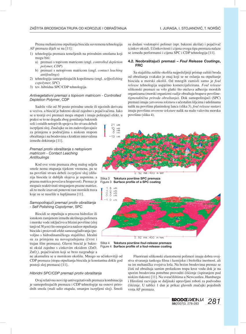
28158(2007)3, 278-283
ZAŠTITA BRODSKOGA TRUPA OD KOROZIJE I OBRAŠTANJA I. JURAGA, I. STOJANOVIĆ, T. NORŠIĆ
Prema mehanizmu otpuštanja biocida suvremena tehnologija AF premaza dijeli se na [11]:
1) tehnologija premaza temeljenih na prirodnim smolama koji mogu biti:a) premazi s topivom matricom (engl. controlled depletion
polymer, CDP)b) premazi s netopivom matricom (engl. contact leaching
antifoulings) 2) tehnologija samopolirajućih kopolimera (engl. selfpolishing
copolymer, SPC)3) tzv. hibridna SPC/CDP tehnologija.
Antivegetativni premazi s topivom matricom - Controlled Depletion Polymer, CDP
Sadrže više od 50 posto prirodne smole ili njezinih derivata u vezivu, a biocid je bakreni oksid zajedno s pojačivačima. Iako se u teoriji ovi premazi mogu otapati i imaju polirajući efekt, u praksi se to ne događa zbog gomilanja bakrenih soli i ostalih netopivih spojeva što stvara debeli iscrpljeni sloj. Značajke su im zadovoljavajuće za primjenu u područjima s niskom stopom obraštanja i na brodovima s kratkim intervalima između dokiranja [11].
Premazi protiv obraštanja s netopivom matricom - Contact Leaching Antifoulings
Kod ove vrste premaza zbog malog udjela smole nema otapanja tijekom vremena, pa se na površini stvara debeli iscrpljeni sloj (difu-zija biocida iz dubljih slojeva je usporena, a prazna matrica povećava hrapavost). Premaz je moguće reaktivirati struganjem prazne matrice, ali to može izazvati ponovni rast morskih trava koje su se naselile u šupljinama [11].
Samopolirajući premazi protiv obraštanja - Self Polishing Copolymer, SPC
Biocidi se otpuštaju u procesu hidrolize ili ionskom zamjenom između akrilnoga polimera i morske vode isključivo u blizini površine (sloj tanji od 30 µm) što omogućava nadzor otpuštanja biocida i proizvodi efekt samozaglađivanja (po-voljno s hidrodinamičkoga stajališta). Idealni su za primjenu na novogradnjama (čvrst i trajan fi lm premaza). Glavni biocid je bakre-ni oksid zajedno s cinkovim oksidom (ZnO, ZnO
2), pojačivačem koji se brzo razgrađuje a
ne akumulira se u morskom okolišu. Mnogo su učinkovitiji od CDP premaza (stopa otpuštanja biocida je konstantna dokle god postoji sloj premaza) [11].
Hibridni SPC/CDP premazi protiv obraštanja
Ovaj relativno novi tip antivegetativnih premaza kombinacija je samopolirajućih premaza i CDP tehnologije na osnovi priro-dnih smola (mali udio otapala, smanjen iscrpljeni sloj). Smoli
su dodani vodotopivi polimer (npr. bakreni akrilat) i pojačivač (cinkov oksid). Učinkovitosti i cijena ovoga tipa premaza nalaze se između performansi i cijena SPC i CDP tehnologija [11].
4.2. Neobraštajući premazi – Foul Release Coatings, FRC
Sa stajališta zaštite okoliša najpoželjniji pristup zaštiti broda od obraštanja svakako je onaj koji se ne oslanja na otpuštanje biocida u morski okoliš. Od mnogih zamisli samo je foul release tehnologija uspješno komercijalizirana. Foul release silikonski premazi su vrlo glatki što otežava adheziju morskih organizama (morski organizmi radije obraštaju hrapave površine-tigmotaktična priroda obraštanja). Dok samopolirajući (SPC) premazi imaju zatvorenu teksturu s učestalim šiljcima i udolinama nalik na površinu planinskog lanca (slika 3), foul release sustavi imaju površinu otvorene teksture nalik na malo valovitu morsku površinu (slika 4).
Slika 3 Tekstura površine SPC premaza Figure 3 Surface profi le of a SPC coating
Slika 4 Tekstura površine foul-release premaza Figure 4 Surface profi le of a foul-release coating
Fluorirani silikonski elastomerni polimeri imaju dobra svoj-stva stvaranja tankoga fi lma i kemijsku i biološku inertnost, ali su im mehanička svojstva loša. Na brzim brodovima premaz se čisti od obraštaja samim prolaskom trupa kroz vodu dok je na sporim brodovima potrebno provoditi čišćenje (ispiranjem pod niskim tlakom) [11]. Na sveučilištima u Newcastleu, Hamburgu i Hirošimi razvijaju se daljinski upravljani roboti za podvodno čišćenje. U tablici 1 dan je prikaz glavnih značajki pojedinih vrsta AF premaza.

282 58(2007)3, 278-283
I. JURAGA, I. STOJANOVIĆ, T. NORŠIĆ ZAŠTITA BRODSKOGA TRUPA OD KOROZIJE I OBRAŠTANJA
Tablica 1 Prikaz glavnih značajki pojedinih vrsta AF premazaTable 1 Overview of main properties of AF coatings
Vrsta premaza Svojstva
Premazi s netopivom matricom
- visoka mehanička čvrstoća- prazna matrica pridonosi povećanju hrapavosti brodskog trupa- premaz je moguće reaktivirati struganjem prazne matrice, ali to može izazvati ponovni rast morskih trava koje su se naselile u šupljinama- kratki životni vijek, do 18 mjeseci
Premazi s topivom matricom, CDP
- visoki udio prirodne smole, bakar kao glavni biocid- niska mehanička čvrstoća- debeli iscrpljeni sloj zbog gomilanja netopivih spojeva (soli, nečistoće)- pruža zaštitu u trajanju do 36 mjeseci- cijena najniža među AF premazima bez kositra
Samopolirajući kopolimeri, SPC
- otpuštanje biocida i otapanje polimera u tankom površinskom sloju – efekt samozaglađivanja- čvrst i trajan fi lm premaza – idealno za primjenu na novogradnjama- glavni biocid je bakarni oksid sa cinkovim oksidom kao pojačivačem- stopa otpuštanja biocida je konstantna dokle god postoji sloj AF premaza- zaštita do 60 mjeseci, ovisno o uvjetima u službi
Hibridni CDP/SPC
- mali udio otapala, kontrolirana stopa otpuštanja biocida- trajniji fi lm u odnosu na CDP premaze- učinkovitost i cijena između performansi CDP i SPC tehnologija- životni vijek do 36 mjeseci
Foul-release premazi
- bez biocida- silikonska baza stvara vrlo glatku površinu koja otežava obraštanje- vrlo mekani, podložni mehaničkim oštećenjima- za samočišćenje potrebna je velika brzina plovidbe ili visoka aktivnost broda- 5-10 puta skuplji od ostalih AF premaza
Unatoč atraktivnim značajkama neobraštajućih premaza do
njihove šire primjene nije došlo uglavnom zbog toga što većinu svjetske fl ote čine tankeri i brodovi za rasuti teret koji ne plove pri dostatno velikim brzinama i nemaju dostatnu aktivnost da bi danas dostupni foul release premazi pokazali svoju učinkovitost i opravdali svoju cijenu koja je 5 do 10 puta viša od cijene ostalih AF premaza [10].
5. Alternativni pravci u zaštiti od obraštanja
Kratkotrajno rješenje nakon zabrane korištenja TBT spojeva jesu premazi na bazi bakra koji su danas još uvijek dopušteni, ali strahuje se od trovanja neciljanih skupina organizama. Da bi se razvili netoksični (ili vrlo malo toksični) sustavi potrebno je bolje shvatiti biokemiju morskih mikroorganizama i mehaniku njihove inicijalne adhezije.
Biološke boje
Znanstvenici su identifi cirali i sintetizirali tvari koje nekim morskim organizmima omogućavaju izbjeći obraštanje (npr. koralji), a razvijaju se i tehnologije koje bi omogućile zamjenu biocida u AF premazima s enzimima koji ometaju mehanizme biološke adhezije. Načini industrijske proizvodnje i aplikacije bioloških repelenata još nisu razrađeni [12, 10].
Elektrovodljivi premazi
Površina brodskoga trupa koja je u doticaju s morskom vo-dom prevučena je elektrovodljivim slojem premaza. Hidrolizom
morske vode i reakcijom s Cl- ionima nastaju ClO- ioni s antive-getativnim djelovanjem. Mala struja prolazi kroz fi lm premaza i privlači ClO- ione koji tvore tanak sloj, a nestaju kad se odvoje od trupa (reagiraju s drugim sastavnicama iz morske vode i ne uzrokuju kontaminaciju mora). U procesu ne dolazi do otpuštanja čestica, pa premaz ostaje gladak. Sustav se testira na nekoliko velikih i srednje velikih brodova [10].
6. Tehnologija nanošenja premaza protiv obraštanja
Nanošenje premaza protiv obraštanja na novogradnjama izvodi se u dvije faze: 1) na navozu i 2) u doku. Razlozi tome su sljedeći:- brod će nakon porinuća provesti od 2 do 3 mjeseca u moru,
privezan na opremnoj obali, pa ga je potrebno zaštititi od obraštanja već prije porinuća
- radi ležanja na potkladama nemoguće je zaštititi sva mjesta na podvodnom dijelu trupa
- u fazi izgradnje na navozu na oplatu broda zavaren je određen broj uški i profi la (za transport i manevriranje sekcijama, potporni elementi za porinuće) koje je u doku potrebno od-straniti
- često je nemoguće premaz nanijeti odjednom u zahtijevanoj debljini.U fazi izgradnje broda na navozu na podvodni dio trupa
nanosi se sustav premaza antikorozivne zaštite, te prvi sloj AF premaza (slika 5). Pripremu površine prije nanošenja svakoga sloja i nanošenje zaštitnih premaza važno je izvoditi u propisa-

28358(2007)3, 278-283
ZAŠTITA BRODSKOGA TRUPA OD KOROZIJE I OBRAŠTANJA I. JURAGA, I. STOJANOVIĆ, T. NORŠIĆ
nim okolišnim uvjetima. Priprema površine na navozu izvodi se ručnim postupcima čišćenja, najčešće do čistoće St3 prema ISO 8501-1:1988 normi. Nepovoljni uvjeti okolice (npr. prevelika relativna vlažnost zraka) mogu uzrokovati kondenzaciju na čeliku što će izazvati pojavu korozije na nezaštićenim površinama čelične oplate i gubitak prionjivosti premaza na podlogu (sup-strat). Proizvođač boje jamči svojstva zaštitnih premaza samo u zadanim uvjetima okolice za vrijeme nanošenja i sušenja (stvrdnjavanja). Potrebno je stoga mjeriti parametre okolice i to: relativnu vlažnost zraka (mora biti manja od 85 posto) i točku rosišta (dew point, temperatura čelika mora biti najmanje 3°C viša od točke rosišta).
Kod zaštite od obraštanja novogradnje u doku prva je ak-tivnost pranje podvodnog dijela trupa pod visokim tlakom i odmašćivanje. Slijedi skidanje montažnih i drugih privremenih elemenata, te steel work i priprema površine koja se provodi pjeskarenjem do čistoće Sa 2.5 prema ISO 8501-1:1988 normi.
Nakon pripreme površine pristupa se nanošenju slojeva antikoro-zivne zaštite i prvoga sloja AF (fl ekanje). Završna faza tehnologije zaštite od korozije u doku jest nanošenje završnoga sloja AF premaza (full coat) na podvodni dio brodskoga trupa (slika 6). AF premazi kojima se zaštićuju bokovi podvodnog dijela (vertikale) i dno broda (fl at bottom) moraju odgovarati ponešto različitim zahtjevima, pa se iz tog razloga na bokove i na dno nanose različiti premazi u različitim debljinama (premaz na bokovima u eksploa-taciji se više troši od premaza dna, organizmi koji naseljavaju dno i bokove se razlikuju). Nadzor nad cijelim procesom obavljaju tri inspektora: inspektor brodogradilišta, inspektor proizvođača boje i inspektor brodovlasnika. Nakon svake pojedine faze inspektori svojim potpisima na Primopredajnom listu označavaju završetak iste. Tek kad se utvrdi da nema primjedbi ili da su one uspješno uklonjene prelazi se na sljedeću fazu.
7. Zaključak
Primjenom tehnologije zaštite od korozije osigurava se po-stojanost konstrukcije tj. sposobnost broda da dugi niz godina obavlja svoju funkciju. Zaštita od obraštanja osim uloge u zaštiti od korozije ima izravni utjecaj na performanse broda: njegovu brzinu i potrošnju goriva. Pravilnom uporabom suvremenih tehnologija zaštite od korozije postižu se planirana trajnost i funkcionalnost broda. Premazi koji pružaju bolju i dugotrajniju zaštitu od obraštanja skuplji su. Tehnologije zaštite brodskoga trupa od obraštanja datiraju iz antičkih vremena, ali se još uvijek teži rješenju koje će zadovoljiti aspekte jednostavnog nanošenja, cijene, trajnosti, učinkovitosti i minimalnog utjecaja na okoliš. Da bi se pronašlo još bolje rješenje, potrebno je još mnogo krea-tivnosti, interdisciplinarne suradnje i istraživanja.
Literatura
[1] ESIH, I: “Osnove površinske zaštite”, FSB, Zagreb, 2003[2] JURAGA, I., ŠIMUNOVIĆ, V., STOJANOVIĆ, I.: “Pri-
mjena inhibitora u zaštiti od korozije u brodogradnji”, XVII simpozij Teorija i praksa brodogradnje, Opatija, 2006
[3] FILETIN, T: “Svojstva i primjena materijala”, FSB, Zagreb, 2002
[4] COLLIER, E: “The Boatowner’s Guide to Corrosion”, International Marine/McGraw Hill, USA, 2001
[5] DAVIS, A., WILLIAMSON, P.: “Marine Biofouling: a sticky problem”, NERC News, 1996, http://www.biology.bham.ac.uk/biofoulnet
[6] HEMPEL: Protective coatings manual[7] DAVY, S.: “Marine Biofouling”, 32nd WEGEMT School
on Marine Coatings, Plymouth, 2000[8] “Basic Principles of Ship Propulsion”, http://www.manbw.
com[9] Woods Hole Oceanographic Institution: “ Marine fouling
and its prevention: Chapter 11. The History of the Prevention of Fouling”, United States Naval Institute, 1952
[10] BERTRAM, V.: “Past, Present and Prospects of Antifou-ling”, 32nd WEGEMT School on Marine Coatings, Ply-mouth, 2000
[11] ANDERSON, C.: “TBT Free Antifoulings and Foul Release Systems”, http://www.international-marine.com/antifoulings
[12] “MarinePaint Annual Report”, Goteborg, 2005, http://ma-rinepaint.org.gu.se
Slika 5 Nanošenje AF premaza na navozu Brodogradilišta Ulja-nik, Pula
Figure 5 Application of AF coating on a slipway, Shipyard Uljanik, Pula
Slika 6 Nanošenje završnog sloja AF premaza u doku Brodo-gradilišta Viktor Lenac, Rijeka
Figure 6 Application of fi nal AF coat in dock, Shipyard Viktor Lenac, Rijeka

284 58(2007)3, 278-283
I. JURAGA, I. STOJANOVIĆ, T. NORŠIĆ ZAŠTITA BRODSKOGA TRUPA OD KOROZIJE I OBRAŠTANJA

28558(2007)3, 278-283
ZAŠTITA BRODSKOGA TRUPA OD KOROZIJE I OBRAŠTANJA I. JURAGA, I. STOJANOVIĆ, T. NORŠIĆ

286 58(2007)3, 278-283
I. JURAGA, I. STOJANOVIĆ, T. NORŠIĆ ZAŠTITA BRODSKOGA TRUPA OD KOROZIJE I OBRAŠTANJA

28758(2007)3, 278-283
ZAŠTITA BRODSKOGA TRUPA OD KOROZIJE I OBRAŠTANJA I. JURAGA, I. STOJANOVIĆ, T. NORŠIĆ

288 58(2007)3, 278-283
I. JURAGA, I. STOJANOVIĆ, T. NORŠIĆ ZAŠTITA BRODSKOGA TRUPA OD KOROZIJE I OBRAŠTANJA

28958(2007)3, 278-283
ZAŠTITA BRODSKOGA TRUPA OD KOROZIJE I OBRAŠTANJA I. JURAGA, I. STOJANOVIĆ, T. NORŠIĆ
290 58(2007)3, 278-283
I. JURAGA, I. STOJANOVIĆ, T. NORŠIĆ ZAŠTITA BRODSKOGA TRUPA OD KOROZIJE I OBRAŠTANJA