CONCEPTUAL ISSUES IN GEOMETRICALLY NONLINEAR ANALYSIS OF 3D FRAMED STRUCTURES.pdf

584
___· �I �__I�Y�Rsse�
GENERAL FORMULATION-LINEAR SYSTEM CHAP. 17
in (a) and (17-131): IIp, v + (T 1 - P)(BU + H3)
-V = (¥- /o)Tk'(Y -) (17-132) = A1BU + A1H3 + A2U 2
The variation of HIp considering U as the independent variable is
drfp = AUT[BT(P, - P) + (BTATk'AIB)U + BTAk'(A 1H3 + A2 l 2 -'')] (g)
= AUT[(BTKlB)U - BTH 4]
Requiring [,I to be stationary for arbitrary AU results in (17-126). Note that we could have used the reduced form for V. i.e., equation (d). Also, we still have to determine the constraint forces.
REFERENCES
1. FENVES, S. J., and F. H. BRANIN, JR., "Network-Topological Formulation of Structural Analysis," J. StructuralDiv., A.S.C.E., Vol. 89, No. ST4, August, 1963, pp. 483-514.
2. DIMAGrIO, F. L., and W. R. SPILLARS. "Network Analysis of Structures," J. Eng.Mech. Div., A.S.C.E., Vol 91, No. EM3, June, 1965, pp. 169-188.
3. ARGYRIS, J. H., "The Matrix Analysis of Structures with Cut-Outs and Modifications," Proc. Ninth InternationalCongress Appl. Mech., Vol. 6, 1957, pp. 131--142.
18
Analysis of Geometrically Nonlinear Systems
18-1. INTRODUCTION
In this chapter, we extend the displacement formulation to include geometric nonlinearity. The derivation is restricted to small rotation, i.e., where squares of rotations are negligible with respect to unity. We also consider the material to be linearly elastic and the member to be prismatic.
The first phase involves developing appropriate member force-displacement relations by integrating the governing equations derived in Sec. 13-9. We treat first planar deformation, since the equations for this case are easily integrated and it reveals the essential nonlinear effects. The three-dimensional problem is more formidable and one has to introduce numerous approximations in order to generate an explicit solution. We will briefly sketch out the solution strategy and then present a linearized solution applicable for doubly symmetric crosssections.
The direct stiffness method is employed to assemble the system equations. This phase is essentially the same as for the linear case. However, the governing equations are now nonlinear.
Next, we described two iterative procedures for solving a set of nonlinear algebraic equations, successive substitution and Newton-Raphson iteration. These methods are applied to the system equations and the appropriate re-:.,rrence relations are developed. Finally, we utilize the classical stabilitycriterion to investigate the stability of an equilibrium position.
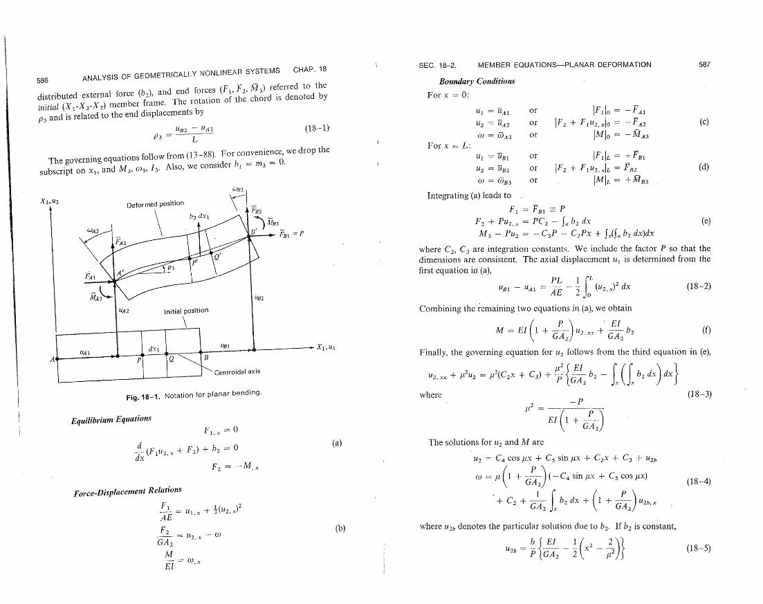
18-2. MEMBER EQUATIONS-PLANAR DEFORMATION
Figure 18-1 shows the initial and deformed positions of the member. The centroidal axis initially coincides with the X direction and X2 is an axis of symmetry for the cross section. We work with displacements (ul, u2, c3),
585
587 SEC. 18-2. MEMBER EQUATIONS-PLANAR DEFORMATION
FR-, ANALYSIS OF GEOMETRICALLY NONLINEAR SYSTEMS CHAP. 18 Boundary Conditions
For x = 0:distributed external force (b2), and end forces (F1, F2. M713) referred to the initial (X 1-X2-X 3) member frame. The rotation of the chord is denoted by
U = Al or IF,| = -FA, p3 and is related to the end displacements by
U2 = UA2 or IF2 + Fu 2.,0o= -FA2 (c) tB 2 UA2 (18-1)-
P3= L = 0)A 3 Or IMIo -MA3 For x = L:
The governing equations follow from (13-88). For convenience, we drop the or IF,IL =+ FB
U2 = UB2 or IF2 + F1 U2 ,xL = FB2 (d)subscript on x1, and M 3, (03, i3. Also, we consider hb = m3 = 0.
CO) = OB3 or IMIL = + MB3
Integrating (a) leads to x 2
FI = FB1 - P
F2 + PU2. = PC 2 - fX b2 dx (e)
M3 - Pu2 = - C3P - C2 Px + fx(Sx b2 dx)dx
where C2, C3 are integration constants. We include the factor P so that the
dimensions are consistent. Thc axial displacement ilt is determined from the
first equation in (a), rv~~~~~182PL I
2u1 - UA1 = (AE (u)2,. dx (18-2)
Combining the remaining two equations in (a), we obtain
2. xxM = EI1 + G- + G-A b 2 (f)
Finally, the governing equation for u2 follows from the third equation in (e),
2U2 ,xx + t
2 = #u(C 2 + C3) + .Lb2 - (b 2 dX)dd 2
where~ ~ ~~P A
Fig. 18-1. Notation for planar bending. where (18-3) -P
2t1
EquilibriumEquations EI +--
F 1, = 0 GA2
(a) The solutions for u2 and M are (Ft2, + F2 ) + b2 =0
dx 2 =C COS sx + C5 sinx + C2x + U2b+ C 3 F2 - -Mx
CO I (l + GA) .x C4 sin + Cs COSx) (18-4)
Force-DisplacemenltRelations 2 + C2 + GA 2 b2 dx +( + GA 2 U2b,x
F, u1 ,, _) FE =u1X + 2(U2,)
(b) where Ut2,denotes the particular solution due to b2. If b2 is constant,Fi2 F2 =U2.X - CO
GA2 U2b {GA 2 x (18-5)
12)M P GA2 2 t.c t- = O(, X

589 588 ANALYSIS OF GEOMETRICALLY NONLINEAR SYSTEMS CHAP. 18
Enforcing the boundary conditions on U2, co at x = 0, L leads to four linear equations relating (C2 '" C5). When the coefficient matrix is singular, the member is said to have buckled. In what follows, we exclude member buckling. We also neglect transverse shear deformation since its effect is small for a homogeneous cross section.
We consider the case where the end displacements are prescribed. The net displacements are
lnet = u' = (I - u2b),=O, L (18-6) Onet = O' = (C - U2b,x)x=O, L
Evaluating (18-4) with A2 = oo, we obtain
C2 = (01. - tC 5
C3 = UA - C4
1 - cos L co - o C4 = - C5 .....
sin JtL It sin tL (18-7)
Cs = (u' - u oL)sin L - (CL (o) a)
D = 2(1 - cos uL) - ML sin I1L
Note that D 0 as FtL - 2 . This defines the upper limit on P, i.e., the member buckling load:
47r2 EI - PInax = L2 (18-8)
The end forces can be obtained with (c-e). We omit the algebraic details since they are obvious and list the final form below.
MA3 = M 3 + 0 2 ) - - UA2) r r I 1
MB 3 - MB 3 -+ I b4)20A3 (- uA2)ILLEI3F- 3 (,blB3
- L A )
=FA 2 F 2 L [ B3 + O)A3 - (UB2 U2) 2 - UA2 ) (18-9)
[CB3 + (CA3 - B2 UA2)1 + - (U2 -FB2 = F 2 - L22 -P = FeI T', = -P
PL I2 PL (u ) 2
UB II =- j x dx - - eL fo' IA
where D = 2(1 - cos ML) - uL sin utL
Do = FtL(sin ML - bIL cos ItL) Dq 2 = L(uL - sin /L)
D03 = D(4)1 + 0'2) = (,UL)2 (1 - cos /ML)
SEC. 18-2. MEMBER EQUATIONS-PLANAR DEFORMATION
The i functions were introduced by Livesley (Ref. 7), and are plotted in Fig.18-2. They degenerate rapidly as ylL - 2 . The initial end forces depend on the transverse loading, b2. If b2 is constant,
A2= FB2 - bL 2
' bL 2 (18-10)B3 = (L)2 (1 - 2))
MA3 = - B3
In order to evaluate the stiffness coefficients, P has to be known. If one end, say B, is unrestrainedwith respect to axial displacement, there is no difficulty since FBI is now prescribed. The relative displacement is determined from
P = FI
PL u1 = UA1 + A - Ler
er - (U2 )2 dx = e( jL, uA2,uB, OA, COB)
2er = 5(C)2 + [4 ( - t2) + ¢i6 (cJB3 - J-)A3) C5
+ l)7(O.B3 - 09A3)2 + -2 )
Dq04 = L sin L (18-11)
C'5 =2 C,
(/L)B3 3b3
- (ic3) + (14 2- UA2 0,
134- o3
7= (L sin tL)2 gtL(ML - sin IL cos iL) + 2(1 - cos /tL)2
¢6 = (1 - cos uL) 7 -,-2T
5 (1- Cos L){ )~ ( L)22 ,tL2 9 _ sin L cos MIIll. I '- " e ' ' k ) J
We call er the relative end shortening due to rotation. However, when both axial displacements are prescribed, we have to resort to iteration in order to evaluate P since e, is a nonlinear function of P. The simplest iterative scheme is
p(i+1) = AE nL- ( r
- u4 1) + AEe (18-12)
and convergence is rapid when ML is not close to 2. Expressions for the incremental end forces due to increments in the end
displacements are needed in the Newton-Raphson procedure and also for stability analysis. If L is not close to 27, we can assume the stability functions

SEC. 18-3. MEMBER EQUATIONS-ARBITRARY DEFORMATION 591 590 ANALYSIS OF GEOMETRICALLY NONLINEAR SYSTEMS CHAP. 18
where the incremental initial end forces are due to loading, b2 . We can 00 obtain an estimate for de,. by assuming Au 2 x is constant. t
ude, 1 u Au dx-2 U2,)x( UA2/ B2 ALA (18-14)
.... d V
The coefficients in (18-13) are tangent stiffnesses. They are not exact since02 1
we have assumed i and A 2, constant. To obtain the exact coefficients,1
we have to add1
+¢>2 1
LE oAl + o)B 2-- '1, d(2uL)1 L ¢;· · L
1 dL (18-15)d0 =
I df(PL) I L
Il=dPd(p.L) -2LI3 ,1
6 11 2 to d,, and similar terms to dMBr, ..., dFl. The derivatives of the stability functions are listed below for reference:
2(L L)2 sin 1cL I+3 4 = L +
D ML
I 4d312 = -27 (18-16) (L 1i 2112~E =
II
'l =- f{1 - 0/ + 03} + (3; - L)
-I I 52= 13, 41 00 We also have to use the exact expression for de,,
Fig. 18-2. Plot of the q) functions. e r/e, - e.de, = -de,
Au 2 + -i AuB2 + --_e.
ACO +.. -- - A(ML) (18-17)'I zI'A2 vUB2 (W4 OWtB ( AL)
are constant and equal to their values at the initial position, when operating in the equation for dP. An improvement ontl (18-14) is obtained by operating
on (18-9). The resulting expressions are on (18-11), and assuming %ILis constant. AWA3 [ 03 (AuI 2 - AuA2)El
dMB3 = dM43 + L | A0A3 + 2 ALCO3L- A 18-3. MEMBER EQUATIONS-ARBITRARY DEFORMATION
The positive sense of the end forces for the three-dimensional case is shownA 2 El f3 AO 3-A -A2) in Fig. 18-3. Note that the force and displacement measures are referred to
dF.123= dF~2 -- EL-- Acos3 + ACOA3 -- (A 2 - AUA2) the fixed member frame. The governing equations for small rotations were = dFApd u 2 dP (18-13) derived in Sec. 13-9. They are nonlinear, and one must resort to an approximate
- (AuUBB AUA2) - L method such as the Galerkin schemet in which the displacement measures are L 2
expressed in terms of prescribed functions (of x) and parameters. The problem
dFs2 = dF 2 - (dFA 2 - dFA2) is transformed into a set of nonlinear algebraic equations relating the param
dFl = dP dFA1 =- dP eters. Some applications of this technique are presented in Ref. 5.
dP = AE (AU - Au 1 ) + AE de, 1-This method is outlined in Sec. 10-6.L

SEC. 18-3. MEMBER EQUATIONS-ARBITRARY DEFORMATION 593 592 ANALYSIS OF GEOMETRICALLY NONLINEAR SYSTEMS CHAP. 18
Force-DisplacemnentRelations
A-__ + ± )1. (3u)s2). - . U. 3, 1)u,, +
1 ( 2,
12 +u
2, 3,+ +
+ , , )
) + 2
X3 r Ml+ U,2, - (03 =
G A12 + A23 J 7
, )B1
J3, 1 2 G A23 A3
MJ, 01, -GJ fI = EI1r 4,
M2 M 3FZ.1 (903,1l ,2,1 =EI2 El 3
1 XB1 f + o, 1 = (CrM + X3 rF 2 + X2 rF 3 )
-*- X1 GJ
Boundary Conditions (+' for x = L, - for x = 0)
P= +F1
P(Us, + -X J)o,1) + F2 = + F23 x3 P2 L P(us3 1 - 2(). 1) + F3 = F3
-
Note: The centroidal axis coincides Mr + MT + P( 3 Us2 , 1 - 2u 3 , 1 + 1(01, 1) -=iT
with X1. X2 and X3 are prin- M 2 = ±M 2 M 3 = M M 4 , = ± M4, cipal inertia directions.
To interpret the linearization, we consider (13-81). If one neglects the Fig. 18-3. Notation for three-dimensional behavior. nonlinear terms in the shearing strains,
Y12 - u/1 , 2 + 2. 1 (a)If we consider b1 = 0, the axial force F1 is constant along the member and the Y13 Ul1 ,3 + 3. 1nonlinear terms involve )1 and coupling terms such as F'2u 3, 1; (otM 2 ; etc.
called the Kappus takes the extensional strain asNeglecting these terms results in linearized equations, equations. Their form is:
1U 1 +[ll tl±, + 3 , + (x2
+ X3)o, 1 (b)+ 1x-=X3-o
Equilibrium Equations and assumes F1 = P Ib,(X22 + X32)dA =
d 'fX3(X2 - x3)dA 0 (c) [P(ts2,1 + - 3 0 1, 1) + F2 ] + b2 = 0 j 2(x" x2)cdA 0dx, fjjr(X22 + =3
d d- [P(us3, I - -x2)1,1) + F3] + b3 = 0
one obtains (13-81). Equations (c) are exact when the section is doubly symmetric. Assumptions (a) and (b) are reasonable if col, 1 is small w.r. to u2 , and
d - U3, . However, they introduce considerable error when o , is the dominant 1,, + M;., +±, 1 + r [P(7 3u,,, 1 - X2US 3, I + jill, ,)]= 0 term. This has been demonstrated by Black (Ref. 5).
M2 .1 - F3 + m2 = 0 When the cross section is doubly symmetric,
M3,1 + F2 + m3 = 0 (18-18) 1 X2 = 3 = X2r = X3r = - 0
,,M11 - M' + m¢ = 0 A2 3 (18-19) 1 = r2
= + + / A 91A

594
_____ -I C I11--·"-""·1�·I·II�··IYIIIIIIRllsBa�R��
ANALYSIS OF GEOMETRICALLY NONLINEAR SYSTEMS CHAP. 18
(r is the radius of gyration with respect to the centroid) and the problem uncouples to
1. Flexure in X1 -X 2 plane 2. Flexure in X1-X3 plane 3. Restrained torsion
We have already determined the solution for flexure in the X1-X2 plane.
If we introduce a subscript for yt and bj,
2(2) =- (A13)2 -P (18-20)
021 = (C2 L) 0231 = l(3L )
and then replace 112
CO2 --C)3U3
4 -U 2 (t)3 - - ) 2U3 (18-21)
F2 - F3 -->M3M2.
F3 - -F 2 M3 - M2
in (18-9), (18-13), we obtain the member relations for flexure in the X1-X 3 frame. For example,
MA3MA3 + LL Ž 23 (11B2 - UA2jMA3 -- 40210A3 + 022(B3L (18-22)
El [,,(/)31()A + )32(B2 + LA3) -RAI = Mi 2 + -L 2 +Ii B (p3 i)]
and F 2 =...
F 3 2 L B2 - 0)42 - (B3 - ) - ( - UA3)
The expressions for the axial end forces expands to
FBt =P FA = -P AE
P -(UBI - u) + AE(e,l + er2 + er3)L 2r {L; d (18-23)
er 2 = 2L (U2.x)2
dxl e'. = - O2 dl
er3 2L (u3. x)2 dx
where er3 is obtained from er2 by applying (18-21). We generate the restrained torsion solution following the procedure described
in Example 13-7. If the joints are moment resisting (i.e., rigid), it is reasonable to assume no warping, which requires f = 0 at x = 0, L. The corresponding solution is summarized below:
SEC. 18-3. MEMBER EQUATIONS-ARBITRARY DEFORMATION 595
r2 P 2 GJ I + P
GJ E,I, 1 + C,.(1 + P)
GJ MB1 -IL ()B1 - (A 1)
MA = -MB1
1+P (18-24)
sinh L LL( + Cr(1 + P))
= ±~GJ(1 + P)
iLx)+ ( C(1 P)) - x + - ssinh (1- coh
We neglect shear deformation due to restrained torsion by setting C, = 0. If warping restraint is neglected,
ErI, = => it 2 = (18-25)4),=> + P
At this point, we summarize the member force-displacement relations for a doubly symmetric cross section. For convenience, we introduce matrix notation:
B {FF2F 3 MlM- = 2 3}B
1[ B = {U1llU2 U3 0)l2(0 2 3}
etc. (18-26) 9B- = 5-ij + kg36 11' + k,("?9 + FIr
'FA = 'A4 + (kBA)'0/B + kAAqlA - 3
where ',Ycontains nonlinear terms due to chord rotation and end shortening
1 3 - tlA3 ); ; 0; 0}; I contains= {AE(er, + er2 + er 3 ); P (UB2 - UA2 ); -L (UBforces duetoL the initial end forces due to member loads; and
AE
L,
EI3 EI3 2523 L 3
El2 El2
L3 0 3 3 L 2
kBB = 1GJ ¢, L
El2Sym
L
21 EI 3 L
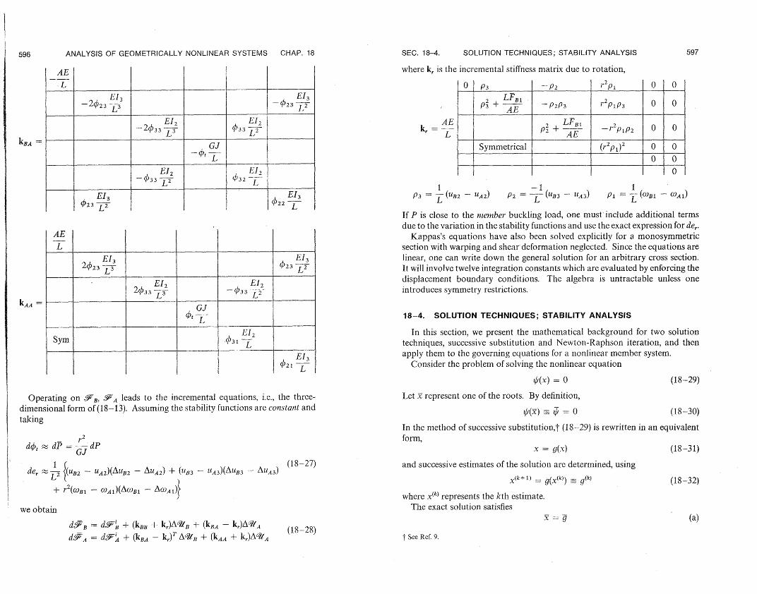
596 ANALYSIS OF GEOMETRICALLY NONLINEAR SYSTEMS CHAP. 18 SEC. 18-4. SOLUTION TECHNIQUES; STABILITY ANALYSIS 597
.
AE where k, is the incremental stiffness matrix due to rotation,
IL El2 0 P3 -P2 r2pi 0 0
EI3 EI3 2 LF,, .
AE - P2P3 2 P1P3 0O 0-2423 -L - 234
PSymmetr+ical
El 2 AE 2 L+Bl 33 - L |-,2P1P2 0 i
IEGJ Symmetrical (r2p1)2 00 i 0
- t__L ...... 0OO - 2c)33 EIL2 I O 0EI2- 033 L-2 ,/32 -
lI 2
I -1 1 EI3 EI3 i P3 - LL-(UB2 - UA2) P2 = L (UB3 - 11A3) P = L-(OBl - OA)L
023 L2 )22L If P is close to the nlember buckling load, one must include additional terms due to the variation in the stability functions and use the exact expression for de,.
.
AE Kappas's equations have also been solved explicitly for a monosymmetric L section with warping and shear deformation neglected. Since the equations are
El33EI 3 linear, one can write down the general solution for an arbitrary cross section.
2423 L 423720~,i It will involve twelve integration constants which are evaluated by enforcing the displacement boundary conditions. The algebra is untractable unless one
El, E12 2033 L-7 introduces symmetry restrictions.
.... _..
I01 GJ--L-J 18-4. SOLUTION TECHNIQUES; STABILITY ANALYSIS
.......,_
In this section, we present the mathematical background for two solution Sym .431 LL_ techniques, successive substitution and Newton-Raphson iteration, and then
EL3 apply them to the governing equations for a nonlinear member system. 021 L Consider the problem of solving the nonlinear equationL
(x)= 0 (18-29)
Operating on 3'BF, -SAleads to the incremental equations, i.e., the three- Let x represent one of the roots. By definition, dimensional form of (18-13). Assuming the stability functions are constant and ¢(/)-- ¢= 0 (18-30) taking
In the method of successive substitution,t (18--29) is rewritten in an equivalent 2
r form, dqt P = r- dP x = g(x) (18-31)GJ
(18-27) and successive estimates of the solution are determined, using de, L
2 {(UB2 - UA2)(AUB2 - AUA 2 ) + (B3 - 11A 3)(AUB3 - AUA3 )
X(k +1) = g(x(k)) _ (k) (18-32) + r2
((OB1 - (OAl)(AB1 - AOA1)} where x(k) represents the kth estimate.
we obtain The exact solution satisfies x = 9 (a)
deB = di7B + (kBB + kr)A/inB + (kBA - kr)Aq/A
dgA = d> + (kBA - kr)T AWIB + (kAA + k,)A 0°IA (18-28)
t See Ref. 9.

598 ANALYSIS OF GEOMETRICALLY NONLINEAR SYSTEMS CHAP. 18
Then, - _ g(k) (b)
Expanding g in a Taylor series about x(k),
g(k)g(k) ±t g~'(i~~ - x(k))+ ± fg( '- x(k))2 + ... (c)+ (k)tXUX_ \()) + Igkx,X _ k)
and retaining only the first two terms lead to the convergence measure -- + 1) = ( X(k))fgxl (18-33)
where 5k is between x(k) and T. In the Newton-Raphson method,t q() is expanded in a Taylor series about
¢() = V,(k) + Ok X j-(,AX)2 + -. = 0 (a)
where Ax is the exact correction to x(k), Ax = - x(k) (b)
An estimate for Ax is obtained by neglecting second- and higher-order terms:
Ax(k) = _/(k)(k) (18-34)
x(k) x.(k) + Ax( x (k+ ) = X(k) + (k)
The convergence measure for this method can be obtained by combining (a) and (18-34), and has the form
( - x(k +l)) ¢ (k -= (S - X?(k)) 2 I '.Ix=,, (18-35)
Note that the Newton-Raphson method has second-order convergence whereas successive substitution has onlyfirst-order convergence.
We consider next a set of n nonlinear equations:
, = / , , 2 mn}= 0 (18-36),/ = ¢,X¢. X2,... -, XJ) An exact solution is denoted by . Also, qi(K) = .
In successive substitution, (18-36) is rearranged to
ax = - g (18-37)
where a, c are constant, g = g(x), and the recurrence relation is taken as
axik+ 1)= C -- g(k) (18-.38) The exact solution satisfies
a =c - (a) Then,
~ a(~ - x(k+ )) = _(g - g(k)) (b)
f See Ref. 9.
SEC. 1-4. SOLUTION TECHNIQUES; STABILITY ANALYSIS 599
Expanding g in a Taylor series about x(k),
= g(k) + g(k)_Ix_~x +I
x(k)) ·+ ...
. ,n (c),2· F,, g1 ,2 g, 1
F- g]j _ 92,1 9212 '. 9, n2 (d)g= x Ln g,, 2.
Lg,,.I g , 2 ... gn,,,j and retaining only the first two terms results in the convergence measure
(x - x(k+ ))= a - lg, I (x - x(k)) (18-39)
where 5k lies between xk and . For convergence, the norm of a- g, must be less than unity.
The generalized Newton-Raphson method consists in first expanding ()about x),
,(k)= q,!i) + + f(k)dd2J = 0 where
d*f(k)(= Ax , , x}
d2_, = d2¢0} (18-40)
d_,j = (x)T -V(Ax) L',,X,. Xi
Neglecting the second differential leads to the recurrence relation
d,4 (k)= (k) AX(k)= _/(k) x(k+ 1)= x(k) + AX(k) (18-41)
The corresponding convergence measure is
"I( - x (k + 1)) = -1 d2qL, (18-42)
Let us now apply these solution techniques to the structural problem. The governing equations are the nodal force-equilibrium equations referred to the global system frame,
= p, - =0 (18-43) where '~e contains the external nodal forces and -P, i is the summation of the member end forces incident on node i. One first has to rotate the member end forces, (18-26), from the member frame to the global frame using
!o = ( ,on)y.-
ko = ()k.Foon (a)
In our formulation, the member frame is fixed, i.e. g," is constant. We introduce the displacement restraints and write the final equations as
¢ =P, -P., =0 P., P + Pr + KU (18-44)
600 601
ANALYSIS OF GEOMETRICALLY NONLINEAR SYSTEMS CHAP. 18
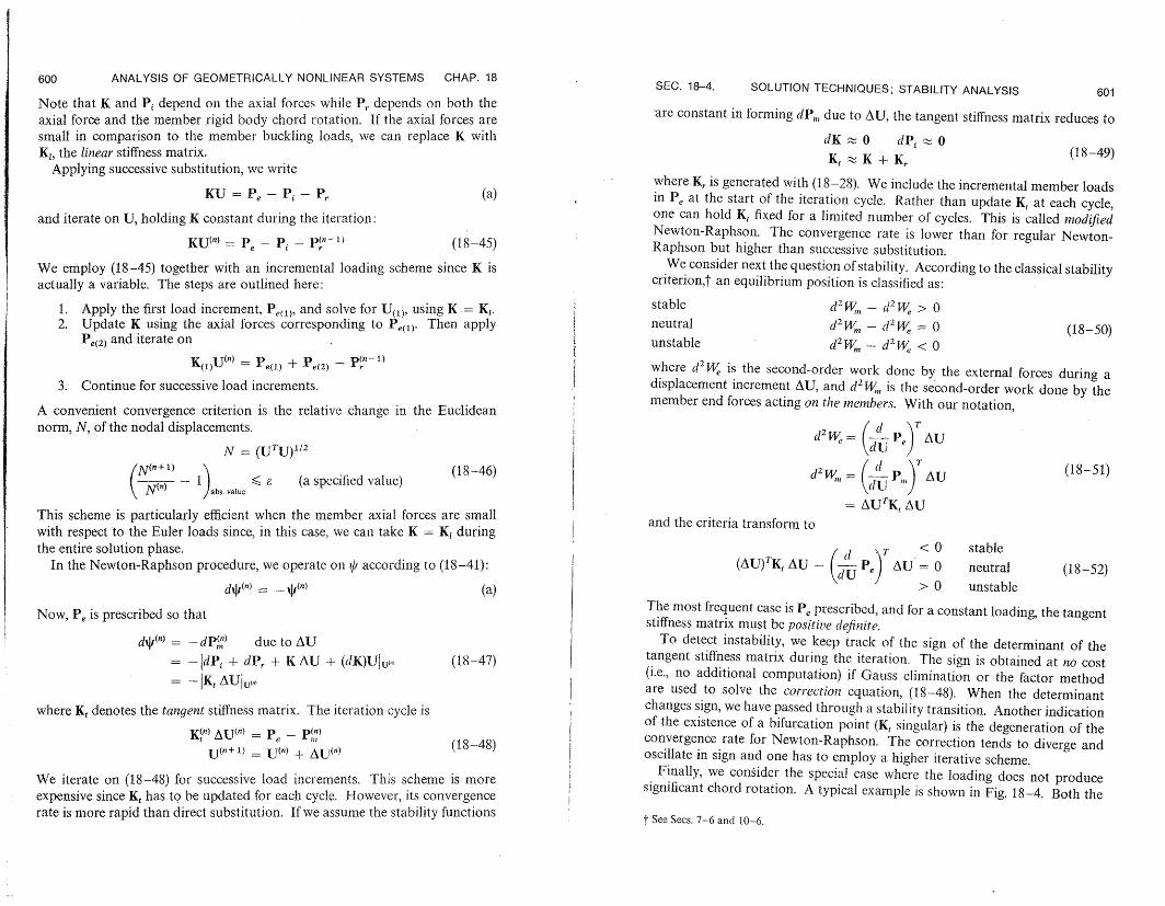
Note that K and Pi depend on the axial forces while P,. depends on both the axial force and the member rigid body chord rotation. If the axial forces are small in comparison to the member buckling loads, we can replace K with KI, the linearstiffness matrix.
Applying successive substitution, we write
KU = Pe-Pi - P, (a)
and iterate on U, holding K constant during the iteration:
KU(") = P - Pi - P(n-l (18-45)
We employ (18-45) together with an incremental loading scheme since K is actually a variable. The steps are outlined here:
1. Apply the first load increment, Pe(1), and solve for U(,,, using K = K. 2. Update K using the axial forces corresponding to Pe(l) Then apply
Pe(2 ) and iterate on
K()U(" = Pe(l) + Pe( 2 ) - p(n-
3. Continue for successive load increments.
A convenient convergence criterion is the relative change in the Euclidean norm, N, of the nodal displacements.
/2N = (UTU)1
N(n+1) < e (a specified value)
(18-46) N1 ) abs.vauc
This scheme is particularly efficient when the member axial forces are small with respect to the Euler loads since, in this case, we can take K = K during the entire solution phase.
In the Newton-Raphson procedure, we operate on //according to (18-41):
dqP(') - _ (n) (a)
Now, Pe is prescribed so that
d+(") = -dP(') due to AU =- - dPi + dP, + K AU + (dK)IJUl,. (18-47)
= -IK AUI U,.
where Kt denotes the tangent stiffness matrix. The iteration cycle is
K?") AU(n) = Pe - P() (18-48)
U(n +1) = U(n) + U
We iterate on (18-48) for successive load increments. This scheme is more expensive since Kt has to be updated for each cycle. However, its convergence rate is more rapid than direct substitution. If we assume the stability functions
SEC. 18-4. SOLUTION TECHNIQUES; STABILITY ANALYSIS
are constant in forming dP,,, due to AU, the tangent stiffness matrix reduces to
dK 0 dPi 0 K,t K + K, (18-49)
where K, is generated with (1.8-28). We include the incremental member loads in Pe at the start of the iteration cycle. Rather than update Kt at each cycle, one can hold Kt fixed for a limited number of cycles. This is called modified Newton-Raphson. The convergence rate is lower than for regular Newton-Raphson but higher than successive substitution.
We consider next the question of stability. According to the classical stabilitycriterion,? an equilibrium position is classified as:
stable d2W,, -d2We > 0 neutral d2W - d22,We = 0 (18-50)unstable d2 Wm- d2We < 0 where d2W is the second-order work done by the external forces during a displacement increment AU, and d2W., is the second-order work done by the member end forces acting on the members. With our notation,
d2W = ( Pe)AU
d2 W,= (d P)TAU (18-51)
= AUTK, AU and the criteria transform to
<0 stable
0 neutral(AU) TKAU - (PAe)TU (18-52) >0 unstable
The most frequent case is P, prescribed, and for a constant loading, the tangentstiffness matrix must be positive definite.
To detect instability, we keep track of the sign of the determinant of the tangent stiffness matrix during the iteration. The sign is obtained at no cost (i.e., no additional computation) if Gauss elimination or the factor method are used to solve the correction equation, (18-48). When the determinant changes sign, we have passed through a stability transition. Another indication of the existence of a bifurcation point (K, singular) is the degeneration of the convergence rate for Newton-Raphson. The correction tends to diverge and oscillate in sign and one has to employ a higher iterative scheme.
Finally, we consider the special case where the loading does not produce significant chord rotation. A typical example is shown in Fig. 18-4. Both the
t See Secs. 7-6 and 10-6.

602 ANALYSIS OF GEOMETRICALLY NONLINEAR SYSTEMS CHAP. 18 REFERENCES 603
frame and loading are symmetrical and the displacement is due only to short- 4: BORGERMEISTER, G.. and H. STEUP: Stabilitis.theorie, Part 1, Akademie-Verlag, Berlin, 1957.ening of the columns. To investigate the stability of this structure, we deletet
the rotation terms in K, and write 5. CHILVER, A. H., ed.: Thin-Walled Structures, Chatto & Windus, London, 1967. 6. VLASOV, V. Z.: Thin Walled Elastic Beans, Israel Program for Scientific Transla-
Kt = K + K = K,(,) (18-53) tions, Office of Technical Services. U.S. Dept. of Commerce, Washington, D.C., 1961. 7. LiVEsLEY, R. K.: Matrix Methods of Structural Analysis, Pergamon Press, London,
where K' is due to a unit value of the load parameter a2. The member axial 1964. forces are determined from a linear analysis. Then, the bifurcation problem 8. ARGYRIS, J. H.: IRecent Advances in Matri Metholds of StructuralAnalysis, Pergamonreduces to determining the value of )2for which a nontrivial solution of Press, London, 1964.
(K + 2AK)AU = O (18-54) 9. HILDEBRAND, F. B.: Introlduction to Nutnerical Analysis, McGraw-Hill, New York,
1956. exists. This is a nonlinear eigenvalue problem, since K = K(2). 10. GALAMBOS, T. V.: Structural Members: and Frames, Prentice Hall, 1968.
11. BRushI, D. and B. ALMROTH: Buckling of Bars, Plates, and Shells, McGraw-Hill,
2X IX 2X New York, 1975.
I IqI I
I I I
7 77///,7
Fig. 18-4. Example of structure and loading for which linearized stability analysis is applicable.
In linearized stability analysis, K is assumed to be K1 and one solves
K AU = -2K,. AU (18-55)
Both K, and K' are symmetrical. Also, K, is positive definite. Usually, only the lowest critical load is of interest, and this can be obtained by applying inverse iteration to
(-K;)AU = 72K,AU
- 1 (18-56)=.
REFERENCES
1. TIMOSHENKO, S. P., and J. M. GERE: Theory of Elastic Stability, 2d ed., McGraw-Hill, New York, 1961.
2. KOLLBRUNNER, C. F., and M. MEISTER: Knicken, Biegedrillknicken, Kippen, 2d ed., Springer-Verlag, Berlin, 1961.
3. BLEICH, F.: Buckling Strength of MAetal Structures, McGraw-Hill, New York, 1952.
t Set pi = P = P3 = 0 in (8-28). t See Refs. II and 12 of Chapter 2.
Ii i
Index
Associative multiplication, 8 Constraint conditions treated. with La-Augmented branch-node incidence ma- grange multipliers, 76, 80
trix, 124, 222 Curved member Augmented matrix, 33 definition of thin and thick, 434 Axial deformation, influence on bending thin, 487
of planar member, 472 slightly twisted, 487
Bar stiffness matrix, 180 Bifurcation; see Neutral equilibrium
Defect, of a system of linear algebraic
Bimoment, MO}, 373 equations, 31
DeformationBranch-node incidence table, 121, 145 for out-of-plane loading of a circular
member, transverse shear, twist, andC4, C., C,,,.-coefficients appearing in bending, 498
complementary energy expression for planar member, stretching andfor restrained torsion, 387, 388, 416 transverse shear vs. bending, 454
Canonical form, 58 Deformation constraintsCartesian formulation, principle of vir- force method, 573
tual forces for a planar member, 465 displacement method, 576Castigliano's principles, 176 variational approach, 583Cayley-Hamilton Theorem, 63 Deformed geometry, vector orientation,Center of twist, 383, 389 239Characteristic values of a matrix, 46 Degree of statical indeterminacyChord rotation. p, 586 member, 555, 567Circular helix, definition equation, 84, 86 truss, 210Circular segment Determinant, 16, 37, 39
out-of-plane loading, 504 Diagonal matrix, 10restrained warping solution, 509 Differential notation for a function, 70, 72,
Classical stability criterion 79continuum, 256 Direction cosine matrix for a bar, 119member system, 601 Discriminant, 40, 59 truss, 170 Distributive multiplication, 8
Closed ring, out-of-plane loading, 503 Cofactor, 19 Column matrix, 4 Echelon matrix, 29 Column vector, 4 Effective shear area, cross-sectional prop-Complementary energy erties, 302
continuum, 261 Elastic behavior, 125, 248 member system, 572 End shortening due to geometrically nonplanar curved member, 434 linear behavior, 589 restrained torsion, 385; 387, 388 Engineering theory of a member, basic unrestrained torsion-flexure, 301 assumptions, 330, 485
Conformable matrices, 8, 35 Equivalence, of matrices, 27 Connectivity matrix, member system, 563 Equivalent rigid body displacements, 334, Connectivity table for a truss, 121, 143. 414, 430 Consistency, of a set of linear algebraic Euler equations for a function, 73
equations, 31, 44 Eulerian strain, 234
605

606 INDEX INDEX 60i
First law of thermodynamics, 248Fixed end forces
prismatic member, 523thin planar circular member, 528
Flexibility matrix arbitrary curved member, 515circular helix, 534planar member, 462prismatic member, 345, 521thin planar circular member, 526
Flexural warping functions, 296, 300fn Frenet equations, 91
Gauss's integration by parts formula, 254Geometric compatibility equation
arbitrary member, 499continuum, 259, 264member system, 569planar member, 463, 466prismatic member, 355truss, 160, 212, 216, 223unrestrained torsion, 279, 315
Geometric stiffness matrix for a bar, 200Geometrically nonlinear restrained torsion
solution, 595Green's strain tensor, 234
Hookean material, 126, 249Hyperelastic material, 248
Incremental system stiffness matrix member system, 601truss, 193
Inelastic behavior, 125Initial stability
member system, 562truss, 137
Invariants of a matrix, 59, 62Isotropic material, 252
Kappus equations, 592Kronecker delta notation, 11
Lagrange multipliers, 76, 80, 583Lagrangian strain, 234Lame constants, 253Laplace expansion for a determinant, 20,
38Linear connected graph, 218Linear geometry, 120, 143, 237Linearized stability analysis, 602Local member reference frame, 92
Marguerre equations, 449, 456Material compliance matrix, 249Material rigidity matrix, 249Matrix iteration, computational method,
201
Maxwell's law of reciprocal deflections, 356
Member, definition, 271Member buckling, 588Member force displacement relations, 537,
546, 556Member on an elastic foundation, 384, 369Mesh, network, 220Minor, of a square array, 19Modal matrix, 52Modified Neuton-Raphson iteration, 601Moment, Me , 3 75Mushtari's equations, 444
Natural member reference frame, 92Negative definite, 58Negligible transverse shear deformation,
planar member, 443, 454, 498Network, topological, 220Neutral equilibrium, 170, 256, 601Newton-Raphson iteration, member sys
tem, 598Normalization of a vector, 49Null matrix, 4
One-dimensional deformation measures, 335, 338, 432
arbitrary member, 491Orthogonal matrices and trnasformations,
50, 53Orthotropic material, 250, 251
Permutation matrix, 42, 135Permutation of a set of integers, 16, 37Piecewise linear material, 126, 146Plane curve, 98, 425Poisson's ratio, 252Positive definite matrix, 58, 63Positive semi-definite matrix, 58Postmultiplication, matrix, 8Potential energy function, member system,
571Premultiplication, matrix, 8Primary structure
member system, 568planar member, 463prismatic member, 354truss, 211
Principle minors, 55Principle of virtual displacements
member system, 570planar member, 442
Principle of virtual forces arbitrary member, 490, 492, 512member system, 571planar member, 435, 458prismatic member, 338, 351
Quadratic forms, 57
Quasi-diagonal matrix, 15, 38Quasi-triangular matrix, 39
Radius of gyration, 434Rank of a matrix, 27, 42, 43Rayleigh's quotient, 75, 79Reissner's principle
continuum, 270member, 383, 414member system, 573
Relative minimum or maximum value of a function, relative extrema, 66
Restrained torsion solution, prismatic member
linear geometry, 391nonlinear geometry, 595
Restrained torsion stress distribution and cross-sectional parameters
channel section, 401multicell section, 411symmetrical I section, 398thin rectangular cell, 407
Rigid body displacement transformation, 109
Rotation transformation matrix, 101, 232Row matrix, 4
Self-equilibrating force systems, 160, 211,258
member systems, 568Shallow member, assumptions, 448Shear center, 297, 300, 309, 378, 389Shear flow, 287Shear flow distribution for unrestrained
torsion, 308Similarity transformation, 53, 62Simpson's rule, 475Singular matrix, 22Skew symmetrical matrix, 11Small strain, 120, 235Small-finite rotation approximation, 238Square matrix, 4Stability of an equilibrium position, 171,
195Stability functions (), prismatic member,
589Statically equivalent force system, 103, 106Statically permissible force system, 159,
216, 257Stationary values of a function, 67, 79Stiffness matrix
arbitrary curved member, 516, 520
modification for partial end restraint, 535
prismatic member, geometrically nonlinear behavior, 588, 595
prismatic member, linear geometry, 522Strain and complementary energy for pure
torsion, 280Strain energy density, 248Stress and strain component trnasforma
tions. 249Stress components
Eulerian, 242Kirchhoff, 246
Stress function, torsion, 276Stress resultants and stress couples, 272Stress vector, 240Stress vector transformation, 242Submatrices (matrix partitioning), 12, 36Successive substitution, iterative method
member system, 597truss, 193
Summary of system equations, force equilibrium and force displacement, 561
Symmetrical matrix, 11, 35System stiffness matrix
member system, 548, 550, 565truss, 179, 180, 188, 206
Tangent stiffness matrix for a bar, 193prismatic member, 590, 596
Tensor invariants, 232Torsion solution, rectangle, 281Torsional constant, J, 276, 278, 323Torsional warping function, 274, 377Transverse orthotropic material, 252Transverse shear deformation
planar member, 454, 498prismatic member, 355
Trapezoidal rule, 474'FTree, network, 220Triangular matrix, 12Two-hinged arch solutions, 467, 470
Unit matrix, 10
Variable warping parameter, f, for restrained torsion, 372
Vector, definition (mechanics), 4fn
Work done by a force, definition, 153, 156