069 - Defense Technical Information · PDF filesign data before any new alloy system can be...
36
* - -*a • w o.o.- * 4//FINAL REP'ORT to AIR FORCE OFFICE OF SCIENTIFIC RESEA,(UJ Project Manager: Dr. A. T. RoAensteinl I':'Grant 140. AFOSR 76-29286 Q!4 CREEP-FATIGUE ENVIRONMENT INTERACTIONS IN SUPERALLOES Principal Investigator Regis M. Pelloux professor of Materials Engineering Department of Materials Science and Engineering Massachusetts Institute of Technology Cambridge, MA 02139 April 1981 upp1'@Y for pnbl 10 relL98iSI 8d15 tribdttOn 69l.tod- 815 12 069
Transcript of 069 - Defense Technical Information · PDF filesign data before any new alloy system can be...
* - -*a • w o.o.-
* 4//FINAL REP'ORT
to
AIR FORCE OFFICE OF SCIENTIFIC RESEA,(UJ
Project Manager: Dr. A. T. RoAensteinl
I':'Grant 140. AFOSR 76-29286
Q!4 CREEP-FATIGUE ENVIRONMENT INTERACTIONS IN SUPERALLOES
Principal Investigator
Regis M. Pellouxprofessor of Materials Engineering
Department of Materials Science and Engineering
Massachusetts Institute of TechnologyCambridge, MA 02139
April 1981
upp1'@Y for pnbl 10 relL98iSI8d15 tribdttOn 69l.tod-815 12 069
SECURITY CLAIIIF#CWTI6C 6F TNTS PAE10fela
REPORfINK U-MENTATIO PAGE RZAD INSTRUCTIONS Is
RKPORK CO'PLZTt! ORN81 gr45 IOVTACCESSIONW AC No a M CATAO 061,1
Creep-Fat igue Envirorament Interactions in. Final7
Superalloys l .PROMIG04 _
Cambridge, MA 02139
II. CONTRORLING AGENCY1 NAME AN ADDRESSI Irwtio m~tn t~o)1.SCRT LS . A.me
Ballin APB, DCAYON 20332AQ 0.
16. 0ISTRISIJTION STATEMENT (.1 thmis Report)
Annve for public reluagedistribution unliulta.0
1S. SUPPLEMENTARY NOTES
III. KEY WORDS (Continue oan revese sse ait. necesoryc anid identify by block number)
fatigue, creep, crack growth, nickel base superalloy., Waspaloy, Astroloy,IN 100,, creep-fatigue-environment interactions, micromachanisma of fracture.
20. ABSTRACT (Continue an reveses mid* It necesuary~ and Identify by block niumber)
crack growth mode as a 4.*unction alloy chemistry and microstructure.
Three alloys, conventionally cast and forged Waspaloy, powder metallurgyas-hot isostatically pressed low carbon Astroloy, and powder metallurgysuperplasticall~y forged IN-100 were compared by room and elevated tempevE. Lurej
DO 3 1473 EO!TION OF I NOV 65 15 O@SOLFTE
SECURITY CLAS1SIiCATION 6P THIS PAGE ("v nls En fo
44 _____ _____ ____
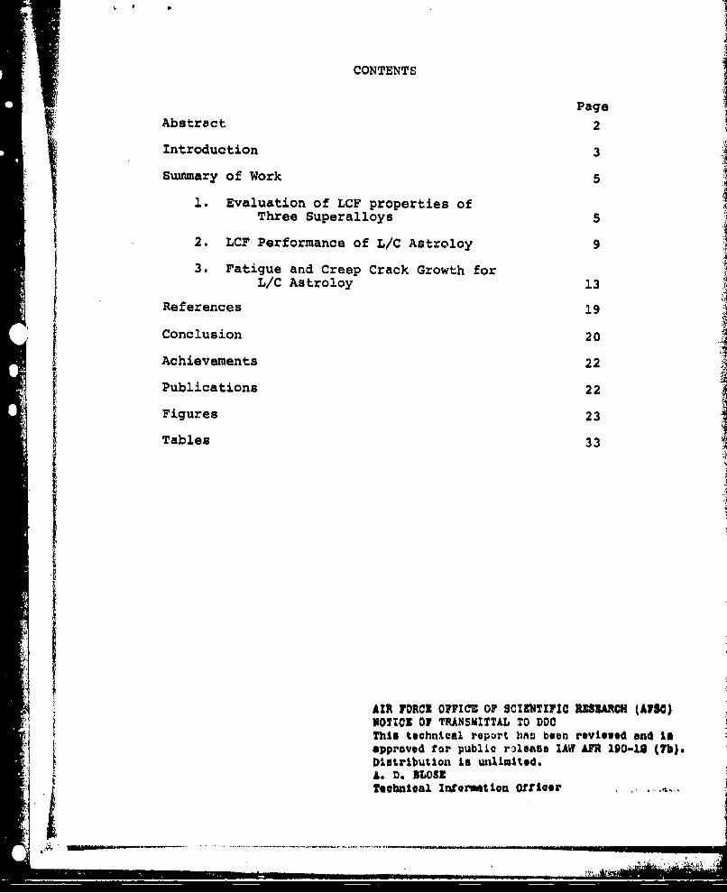
CONTENTS
PageAbstract 2
Introduction 3I Summary of Work 5
1. Evaluation of LCF properties ofThree Superalloys 5
2. LCF Performance of L/C Astroloy 9
3. Fatigue and Creep Crack Growth forL/C Astroloy 13
References 19
"Conclusion 20
Achievements 22
Publications 22
Figures 23
Tables 33
AIfR FORd O7FICE OF SCIENTIFIC RESARCH (ASO)MOTION OF TRANSMITTAL TO DDOThis technical report 111 been reviewed and laapproved for public r3leaBe IAW AFR 190-18 (7b).DistributLion is unlimited.A. D. DLOSZTecbnical Insormtion Offloeor
L i_ _... II ... , ,v;A
ABSTRACT 2
The fatigue-creep-environment interactions in nickel base superalloys wereinvestigated from 6501C to 760C in the low cycle fatigue range and in thecrack growth mode as h function alloy chemistry and microstructure.
Three alloys, conventionally cast and forged Waspaloy, powder metallurgy
as-hot isostatically pressed low carbon Astroloy, and powder metallurgysuperplastically forged IN-100 were compared by room and elevated temperature
low cycle fatigue tes in under control of total strain range. It was found
that at 427 C and 649 C Oaspaloy had the longest fatigue lifetimes followed bylow carbon Astroloy, then IN-lO0, but IN-100 had the highest cyclic flowstress and Waspaloy the lowest,
On the basis of its relatively good combination of fatigue properties, homo-genity and i--tropy resulting from powder processing, and because it can beheat treated to a wide variety of different microstructures, one alloy, lowcarbon Astroloy, was selected for a program to systematically determine theeffects of changes in microstructure on elevated temperature fatigue behavior.Low carbon Astrcloy was heat treaý,. to four very differegl microstructuren withvarious combinations of fine (500A) and coarse (2000-8000A) matrix ~Y'and grainboundaries with and without carbides and primaryj,ý).
Microstructure I in low carbon Astroloy, which is kn to offer the Laetcombination of tensile strength and stress rupture properties, was shown hereto have the best intermediate and elevated temperature low cycle fatiguestrength.
The rates of fatigue crack growth and of creep crack growth were measured inL/C Astroloy in the range of temperatures from 650*C (.64 Tm) to 760*C (.76 Tm).The fgtigue crack growth rates are strongly frequency dependent from 10 Hzto 10-3 Hz (1 cycle/15 min.). Decreasing frequency promotes intergranular creepcavitation during cyclic loading. At very low frequencies, fatigue crack pro-pagation is completely intergranular, and the cyclic crack growth rates areessentially equivilent to the creep crack growth rates.
Creep crack growth in low carbon Astroloy proceeds in a creep-brittle manner inthe range of temperatures from .64 TM to .76 Tm and in the range of nominalstress from . 4 Oy to , 7 ay. Creep crack growth occurs by a process of nucleationand growth of cavities ahead of the crack tip. The kinetics of cavity growth iscontrolled by pow-r law creep deformation.
Oxidation at the crack tip contributes to the creep crack growth rates in the
low temperature range (650*C), where the crack growth rates are small. In thehigh temperature range (760°C), the acceleration of creep crack growth due tooxidation is negligible. Fractography showed that the role played by oxidationis to enhance creep cavitation.
The results of sequential fatigue-creep cracking periods demonstrated that asimplistic linear superposition damage rule cannot be used to predict the crackgrowth rates under combined fatigue-creep loading. The fatigue crack growthrates at a frequency of I liz following a creep loading period are accelerated ab
much as one order of magnitude. This acceleration of fatigue cracking aftercreep cracking is attributed to the creep damage in the crack tip region of the
creep crack.
3
I. Introduction
Fatigue damage limits the useful life of nickel-base
superalloys in many applications. Today there is considerable
emphasis on fatigue in design of gas turbine components. Lack of
a good mechanistic understanding of low cycle fatigue and fatigue
crack growth causes time consuming, expensive generation of de-
sign data before any new alloy system can be used.
The problem of fatigue in nickel-base superalloys is very
complex because these alloy systems are used at temperatures from
0.4 to 0.8 TM. Up to about 0.6 TM the flow stress of y' precipi-
tation strengthened superalloys remain constant with increasing
temperature, while the ductility and tensile strength show only
slight reductions. By contrast the fatigue strength decreases
rapidly with temperature, and the fatigue lifetime can be reduced
by a factor of twenty from room temperature to 760 0 C (0.67 TM).
Obviously, fatigue limits the full utilization of the elevated
temperature strength of nickel-base superalloys.
It was the intent of this program to further the understand-
ing of the mechanisms of fatigue of superalloys. First, different
alloy systems, including Waspaloy, Lxca', and IN-100, ranging
in y' volume fraction from 22 to 55 percent w,!i evaluated and
compared by room and elevated tenipe. '_,.re .low 1.yclc It-ique test-
ing under controlled total strain range. Then on t'e 1basis of
this investigation, powder processed, as-hoi. ,.- 11Eat~ica~ly ,
~ carbon Astroloy was selected for a systematic study
,; & of the influence of grain boundary structure and y'
* . "• 1 . . .............................. -.. * ~ *~
4
size distribution on room and elevated temperature low cycle
fatigue behavior.
The fatigue behavior of the low carbon Astroloy was also
of particular interest because of the novel manner in which it
was processed. Pre-alloyed low carbon Astroloy powder was
consolidated by hot isostatic pressing (HIP) and tested in the
as-consolidated condition without benefit of subsequent forg-
ing. It is already known that HIP powder metallurgy superalloys
exhibit equivalenL monotonic properties in comparison with
conventionally cast and forged alloys, but the cyclic properties
have not yet been fully characterized. It was expected that the
homogeneous isostropic structure produced by powder processing
might be beneficial to. fatigue.
The goals of the research program were:
1. To compare the properties of three different nickel base
superalloys used for turbine disk application under eleva-
ted temperature low cycle fatigue
2. To compared the LCF properties of apowder metallurgy HIP
processed nickel-base superalloy with those of a wrought
alloy having similar chemistry.
3. To determine the effects of temperature and frequency on
the LCF behavior of a powder processed nickel-base super-
alloy.
4. To determine the effects on LCF behavior of changes in y'
size a;,d grain boundary structure in a powder processed
nickel-bas. superalloy.
5
5. To compare the mechanisms of cracking under fully plastic
conditions to those under elastic-plastic conditions at
similar temperatures and frequencies.
Ii. Summary of Work
1. Evaluation of ýCF Properties of three nickel-base
Superalloys.
Three nickel-base superalloys currently used for turbine
disks were studied during the years year; they were Waspaloy, r.
Astroloy, and IN-100. The Waspaloy alloy was cast and hot
worked; the IN-100 alloy was super-plastically forged from an
extruded powder metallurgy (P/M) billet, and the Astroloy alloy
was as-hot isostatically pressed (HIP) prealloyed powder. The
three alloys differ markedly in their volume fractions of the y'
phase. These volume fractions are 22% for Waspaloy, 35% for
Astroloy, and 55% for IN-100.
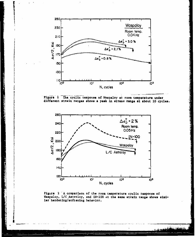
The study of hardening and softening under controlled total
strain range is fundamental to fatigue research. At room temper-
ature, the superalloys were found to cyclically harden to a maxi-
mum Ac a.t 10 cycles, then cyclically soften u til failure.
Figure 1 compares the cyclic response of Waspaloy at different
strain ranges; it is evident that the maximum stress amplitude
is reached at 10 cycles regardless of strain range. The 10 cycle
maximum at room temperature is not confined to Waspaloy. In
Figure 2 the room temperature cyclic response of Waspaloy, L/C
Astroloy, and IN-100 are compared for a strain range of Ae - 2%.
Again the maximum in stress amplitude is observed at 10 cycles for
b -.
6all three alloys. This observation is consistent with the work
of Wells and Sullivan (1), Merrick (2), Stoltz (3), and
Pineau (4).
Hardening may be characterized by the parameter
ACmax -
and softening by the parameter
Aa c- max_ Amin
where A. is the stress range of the fist cycle and Aamin is the
minimum stress range observed after the maximum stress range,
Amax' For Figure 2 the values of f, the hardening parameters of
Waspaloy, L/C Astroloy and IN-100 are: 0.18, 0.32, and 0.42
respectively. The softening parameters are 0.12, 0.15, and 0.22
respectively. In this case it appears that the amount of harden-
ing and softening is related to the volume fraction of y' in the
alloy.
At elevated temperature the cyclic response of the three
superalloys changes. At 800 0 F, there was no softening in L/C
Astroloy or IN-100. At 12000F, softening was again observed in
Waspaloy and L/C Astroloy but curiously not in IN-100. For low
low strain ranges, Waspaloy and L/C Astroloy do soften after
initial hardening, but this 1200OF behavior differs considerably
from behavior at room temperature. At 1200OF the maximum in
stress amplitude is not reached until more than 10% of the
lifetime to failure has elapsed. These observed differences
coupled with the observed absence of softening at 800OF suggest
that the 1200OF phenomenon is mechanistically different from
that at room temperature.
Softening complicates the definition of the cyclic stress-
strain curve. In most oases the room and elevated temperature
cyclic stress-strain curves lie along the monotonic curves;
however, at 12006F softening is great enough at low strain
ranges to shift the cyclic stress-strain curve below the mono-
tonic curve.
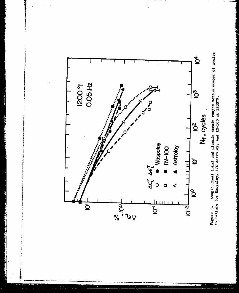
Figure 3 shows that fatigue lifetime correlates well with
total strain range. Lines drawn through both total strain range
and plastic strain range points should extrapolate back to the
same intercept at 1/2 cycle called the "fatigue ductility coefficient"
which corresponds to the monotonic tensile ductility. Since
lifetime versus plastic strain does not extrapolate to a realis-
tic fatigue ductility coeffaioinL, total strain range is preferred
for lifetime prediction.
Lifetime to failure correlates well with total strain ranqe
for all temperatures studied. On this basis Waspaloy has the
best fatigue properties, followed in order by Astroloy and IN-100.
The ranking is not changed by temperature, but the difference
between the alloys seems to increase with temperature.
Figure 3 shows that the relative performance of the three
alloys is the same for all strain ranges of interect. As a
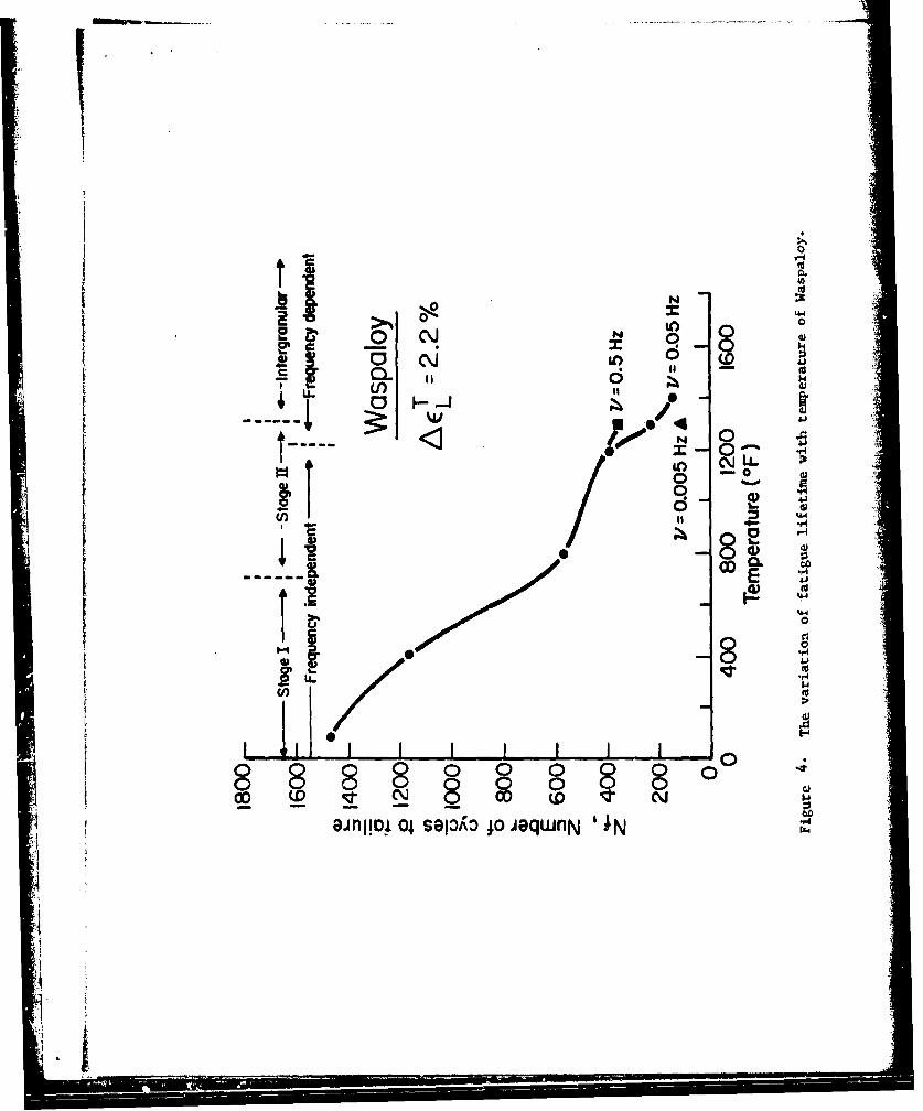
consequence, it was decided to determine lifetimes as a function
of temperature and frequency at one strain range. Results of
... . ..u
L r 8
Ssuch a study with Waspaloy (Aa = 2.2% are plotted in Figure 4.L
The lifetimes are extremely temperature dependent.
Figure 4 suggest that the fatigue behavior of Waspaloy may
be divided into three regimes with the low and high temperature
regime being more temperature sensitive than the middle. Study
of fractographs and review of the literature suggest that the
three regimes correspond to (1) Stage 1 (transgranular crystal-
lographic), (2) Stage II (transgranular non-crystallographic,
(3) Intergranular failure. Regimes I and II are frequency
insensitive, while Regime III is very frequency sensitive. It
is expected that variations in grain boundary structure will
affect only the transition temperature from II to III. Varia-
tion in y' size which affect slip character may affect behavior
in Regime I and the I to II transition temperature.
Si • m mmmmimim ._ ) .• I
2. Low Cycle Fatigue Performance of L/C Astroloy
Low carbon Astroloy was selected as a reference P/M-HIP
superalloy for a study on the effects of changes in micro-
structures on elevated temperature fatigue behavior. Low
carbon Astroloy was heat treated to four very different micro-
structures with various combinations of fine (500A) and coarse
Y(2000-800b matrix ' and grain boundaries with and without
carbides and primary y'. Conventional cast and forged Udimet
700, which is similar in chemical composition to Astroloy, was
also tested.
The four different microstructures are the result of the
heat treatments described in Table I. The characteristic
features of the microstructures are sketched in Figure 5. Each
microstructure is described as follows:
Miurostructure I. The baseline microstructure is characterized
by "wavy" grain boundaries containing both primary Y' and
M2 3 C6 carbides. The matrix y' varies in size with three modes
in the distribution: 0.8um, 0.2pm, and 0.04pm.
Microstructure II. This microstructure contains no grain
boundary y' due to solution above the y' solvus. M2 3 C6 car-
bides are present in the grain boundaries. The matrix y' is
one size, about 0.2pm.
Microstructure III. In this case there are no carbides in the
grain b,:undaries but solution below the Y, solvus results in
some • in boundary and some 0.8 im matrix Y' Oil quench-
ing and sing..e step aging produce fine matrix y' of 0.05 um.
A ___
-i- - -. ~ . -ii.- - -~
10
Microstructure IV. A slow cool results in no grain boundary
carbides and a very broad y' size distribution. One-half of
the 42 per cent y' is 2 pm or larger.
After room and elevated temperature low cycle fatigue
tests, it was found that:
1. At room temperature cyclic hardening following by
cyclic softening was observed. Though initial cyclic flow
stress depended strongly on Y size, saturation flow stress
did not.
2. At 427 0 C and 538 0C gross discontinuous flow behavior
was observed during the first ten cycles of testing. Discon-
tinuous flow was not observed in low carbon Astroloy with
predominantly fine 500A y'.
3. At 427 0 C and 5380C fatigue lifetime and mode of
I crack propagation were related to matrix y' size. Low carbon
Astroloy with only 2000A y' had the shortest fatigue lifetimes
and exhibited both stage I crack initiation and crack propa-
gation along persistent slip bands. Low carbon Astroloy with
the other microstructures which had some fine 500A y' had
longer fatigue lifetimes and exhibited stage I initiation but
stage II propagation.
4. At 6490C and 760 0 C grain boundary structure influenced
fatigue lifetimes. Grain boundaries with both carbides and
primary y' had the longest fatigue lifetimes. Absence of
primary y' and or carbides in the grain boundaries resulted in
4
t 11
transition to intergranular failure and - duced fatigue
lifetimes.
5. at 6490C conventionally cast and forged Udimet 700
had shorter fatigue lifetimes than powder processed as-hot
isostatically pressed low carbon Astroloy.
6. Microstructure I in low carbon Astroloy, which is
known to offer the best combination of tensile strength and
stress rupture properties, was shown here to have the best
intermediate and elevated temperature low cycle fatigue
strength.
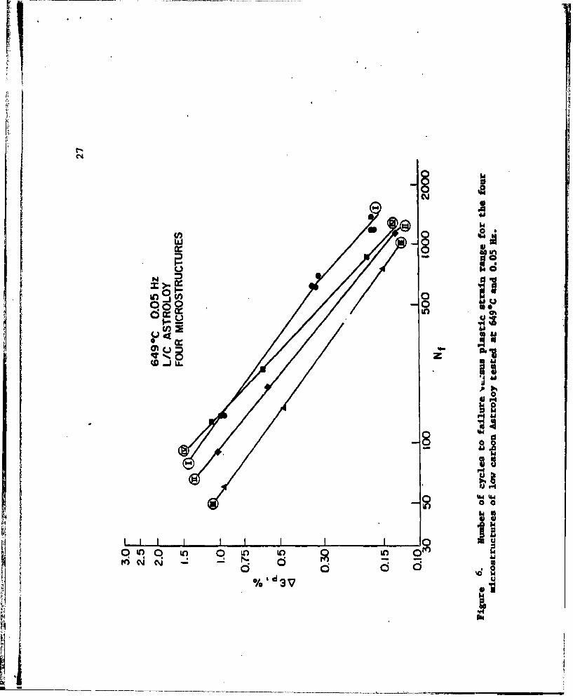
Fatigue lifetime of low carbon Astroloy was found to be
sensitive to microstructure. In Figure 6 the number of cycles
to failure is plotted versus the plastic strain range for LCF
tests at 0.05 Hz and 649 0 C for the four microstructures.
Under these test conditions, Microstructure I is the best
and Microstructure III the worst. In Figure 7 lifetimes to
failure for the four microstructures are plotted versus temper-
ature for a constant total strain range of 2.2%. At room tem-
perature, iifetimes to failure varied even though the satura-
tion plastic strain was the same for each microstructure, sug-
gesting that initial cyclic plastic strain may govern fatigue
lifetime. At 4270C and 538 0 C microstructure II exhibited
shorter fatigue lifetimes than the other three microstructures.
At 6490C and 7600C microstructures II and III show markedly
shorter lifetimes to failure than microstructures I and IV.
ýZjA-_ ia
12
Scanning electron microscopy and optical microscopy of
surface replicas was conducted on failed LCF specimens to
relate differences in fatigue lifetime to modes of fatigue
failure. Modes of fatigue crack initiation and propagation
for various alloys, microstructures and test conditions arelisted in Table II. The predominant mode of failure is
stage I crack initiation along persistent slip bands followed
by stage II transgranular propagation.
The reduction in fatigue lifetime of microstructure 1I
at 427 0C and 538*C was associated with stage I crack propa-
gation along persistent slip bands. Thus, this microstructure
which has no fine 5001 y' apparently resultsin weaker in-
tense slip bands.
The poor fatigue performance of microstructure III at
6490C and 760 0 C was associated with intergranular crack initia-
tion and propagation. Microstructure III has no grain
boundary M2 3C6 carbides. Microstructure II also showed inter-
granular cracking at 649*C and 760*C. Grain boundaries in
microstructure II contain M23C6 carbides but no primary y'.
It is concluded that both primary y' and M C carbides con-
tribute to grain boundary strength in elevated temperature
fatigue.
. i
................................ IIl i --

E 13
3. Fatigue and Creep Crack Growth in L/C Astroloy.
Following the extensive low cycle fatigue work described
in Sections 1 and 2, it was decided to investigate the rates
and mechanisms of fatigue and creep crack growth at elevated
temperatures in the same alloy. One of the main reasons for
this approach was due to the fact that the main problems
associated with the new PM/HIP superalloys is the presence of
small ceramic particles which act as fatigue and crack crack
initiation sites. Consequently, it is important to know the
growth rates of cracks growing from these small defects. The
effects of temperature, frequency, wave shape and environment
were investigated.
A PbI/HIP low carbon Astroloy alloy supplied by Pratt and
Whitney was used in this investigation. Fatigue and creep
crack growth tests were performed with single edge notched
bars. The starter notch was 1 mnm deep. Shallow side grooves
were used in order to maintain a straight crack front during
crack growth. For continuous fatigue crack growth, the crack
length is measured with a traveling telescope with 1 .01 mm
accuracy. For sequential fatigue and creep crack growth
tests, creep crack growth is measured in macrophotographs.
A potential drop technique was used to monitor creep crack
growth.
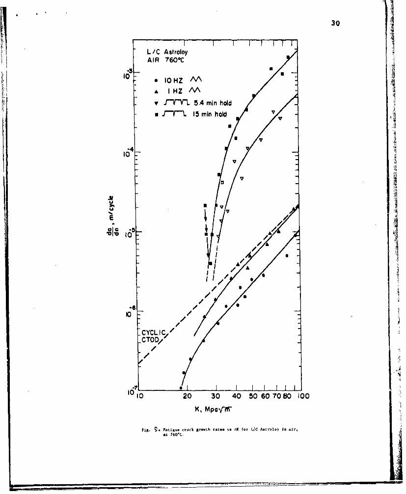
Experimental ResultsThe fatigue crack growth rates in air at 650 0 C and
.14
7600C versus the range of the stress intensity factor AK
are plotted in Figures 8 and 9. The cyclic crack tip opening2AK
displacement (CTOD = &- versus AK is also plotted. (Y is
the yield stress, E is the elastic modulus.) The data covers
the range of AK from 10 to 100 MParm. The three regions of
the typical da/dn- K curve are not fully represented. The
low AXK region remains to be explored at 6500C at low and high
frequencies. In region 2 of the da/dn - AK curve the crack
growth rate increases with decreasing frequency and increasing
hold times. At 760*C the apparent threshold AK increases with
increasing hold times and the region I slope increases markedly
with decreasing frequency.
At high frequencies (10 Hz and 1 Hz) the fracture path
was essentially transgranular at 6500C and 7600C. At low AK
the fracture path is strongly crystallographic which is typical
of low growth rates in y-y' alloy at high temperatures. As AK
increases, the fracture path is less crystallographic, although
it is still transgranular with well-defined striations. The
crack front fans out in each grain indicating a reinitiation
process at the crossing of each grain boundary. The striations
are strongly crystallographic which is typical of a planar slip
process of sliding off and £racture at the crack tip. For the. 5.4
min. and 15 min. hold times, the fracture path is completely
intergranular.
Figure 10 summarizes the fracture modes in a plot of crack
15
growth versus frequency for a AK value of 50 MPa/m. We see
that at low frequencies, and long hold times, the crack
growth rate per cycle is inversely proportional to the fre-
quency indicating a process of fracture by pure creep crack
growth.
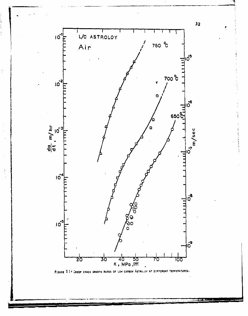
Creep Crack Growth Rate Data
Figure 13 shows the results of constant load creep crack
growth tests at 6500, 7000 and 760 0 C. The data are plotted
as da/dt in m/hour versus K, the stress intensity factor.
Although there is a larger scatter band,-the data is easily
correlated with the K factor at different gross stress levels
at least for the single edge notch specimen used here. This
correlation is in agreement with other results on creep crack
growth in nickel base superalloys. A mathematical analysis
of the stress and strain fields at the tip of a sharp crack
undergoing creep has been recently given by Riedel and Rice
(4). Riedel's analysis shows that the use of K as a correla-
tion parameter for da/dt is justified for high strength, low
ductility, creep resistant alloys.
A detailed fractographic investigation of the creep crack
growth (CCG) specimens shows a completely intergranular frac-
ture path. The grain boundary facets are not sharply out-
lined as they are made up of a network of microvoids. The
voids are spherical in shape and each void appears to be
centered around a second phase particle. There is no indica-
tion of elongation of the voids due to a grain boundary
1........ ..... . ....... ... -- ..........---... .

16
sliding process. There is little or no secondary grain
boundary cracking.
Sequential Fatigue and Creep Crack Growth Tests
A series of tests were performed in air and in vacuum
to study the interactions between sequential crack front ad-
vances due to creep an to fatigue. The tests were conducted
in the following manner: 100 to 300 fatigue cycles at I. Hz
were followed by creep crack growth for given hold times.
This sequence was repeated until the test bar broke, or until
large plasticity effects were observed in the test specimen.
It was found that the creep crack growth rates under
sequential periods of fatigue and creep are greater than
under conditions of steady creep crack growth. There is a
period of accelerated creep crack growth following fatigue
cracking. The creep crack growth rate decreases as the crack
front advances by creep cracking. At the limit, the crack
growth rate reaches tba static crack growth rate.
This transient effect of accelerated CCG may be due to
the following factors:
Creep crack growth is accelerated as long as the
creep crack is growing through the pre-damaged
cyclic plastic zone at the tip of a fatigue crack.
This damage may take the form of a high density of
dislocations or vacancies or of a high concentration
of oxygen atoms which may have been swept into the
grain boundaries by dislocation transport. Creep
w~pr wu. nu
17
crack growth is also accelerated because of the
high tensile stresses present at the tip of the
fatigue crack following cyclic crack growth. It
takes a while for the stresses to relax by creep
to lead to in a decrease of the CCGR.
In smmery, the main results of the crack propagation studies
are:
1. The rates of fatigue crack growth and of creep crack
growth were measured independently in L/C Astroloy in the range
of temperatures from 650 0 C to 760 0 C.
2. It was found that the rates of cracking are better
correlated with K, the stress intensity factor, than with C*integral.
3. The fatigue crack growth rates are strongly frequency
dependent, approaching the pure creep crack growth rate at very
low frequencies (<l cycle / 15 minutes).
4. Sequential fatigue-creep cracking periods demonstrated
that a simplistic superposition damage rule cannot be used to
predict the crack growth rates. Creep crack growth rates
following high frequency (1 Hz) fatigue cycles are an order of
magnitude greater than the creep crack growth rates which should
be expected from continuous creep cracking.
5. Oxidation effects at the crack tip contribute exten-
sively to the creep crack growth rates in the low temperature
range (650 0C). At 7600C, the contribution of oxidation to creep
crack growth is small compared to the creep cavitation damage.
. .... .......... ............... -..-..... .....
18
6. A theoretical model of creep crack growth is
proposed based on time dependent analysis of the crack tip
stress distribution and on a cavity growth mechanism by
power law creep. The model predicts that creep crack growth
rates are a strong function of triaxiality ahead of the crack
tip. With a plastic constraint factor equal to 2, the model
predicts the creep crack growth rates of low carbon Astroloy
within a factor of 10 of the experimental data. This model
of creep crack growth also predicts that the creep crack
growth rate increases with decreasing grain size, decxe•uing
cavity spacing and decreasing threshold cavity nulcation stre 's.
7. A theoretical prediction of creep crack growth rates was
also performed based on the time-dependent crack tip stress
field and with the assumption of a diffusive cavity growth
mechanism. The prediction overestimated the creep crack
growth rates by several orders of magnitude and predicted a
wrong temperature dependence for the creep crack growth rates.
It is concluded that cavity growth by grain boundary diffusion
is suppressed by seve-l c. rders of magnitude during creep
Qavitation in low carbon Astroloy.
-i--
.•...:•. :. • •4... •
References
1. C. H. Wells and C. P. Sullivan, Low Cycle Fatigue Damage
of Udimet 700 at 1400 0 F. ASM Transactions. Quart. 58,
391 (1965).
2. H. T. Merrick, The Low Cycle Fatigue of Three Wrought
Nickel Base Superalloys, Met. Trans. 5, 891 (1974)
3. R. E. Stoltz, Private communication, MIT,(1975).
4. D. Fournier and A. Pineau, Low Cycle Fatigue of Inconel
718 at 2980K and 8230K, Met. Trans. 8A,(1977).
5. H. Riedel and J. R. Rice, Tensile Cracks in Creeping Solids.
ASTM STP 700, p. 112, (1979).
...................................................,. - :2z
. .. , "*,-.-,-.-- -',..--.,.._- - - - -

20
Conclusions
The main achievements of the research work reported here
are:
1. Development and refinement of the test procedures
used to evaluate low cycle fatigue and fatigue-creep crack
growth performance of high strength nickel base superalloys.
2. Detailed evaluation of the role of the intergranular
and transgranular microstructures of Astroloy on its per-
formance in low cycle fatigue.
3. Measurements of the fatigue and creep crack growth
rates in Astroloy as a function of temperature, frequency,
wave shape and hold times.
4. Extensive correlations between the micromechanisms
of fracture and the continuum mechanics parameters on the
one hand and the alloy microstructure on the other hand.
The following research tasks were identifieds
1. A quantitative separation of the initiation and pro-
pagation stages is badly needed. A systematic study of the
creep fatigue growth of short cracks (< 1 mm) may help resolve
this problem.
2. The use of K as a fracture mechanics correlation
parameter at elevated temperatures is purely arbitrary, even
if the correlation of K with the crack growth rates appear
acceptable. The strong time and temperature dependence of
elaRtic stresses at a crack tip make the use of K meaningless.
"There is need fcr a detailed analysis of time-dependent stress
' vid strain distributl.ns at the tip of a growing creep crack.
._ ..

21
3. A great deal of fundamental work remains to be done
to understand the effect of environment on cavitation and
cracking at crack tips.4. The life prediction methodology is at this time
purely empirical. There is a need for an integrated life-
prediction methodology which can account not only for fre-
quency and wave shape effects, but also for sequential periods
of creep and fatigue and for microstructural effects.
Ii
U~.i1

22
Achievements
J. Runkle, Elevated Temperature Fatigue of Nickel BaseSuperalloya, ScD thesis, MIT, February 1978.
J. S. Huang, Fatigue Crack Growth and Creep Crack Growth ofP/M HIP Low Carbon Astroloy at High Temperature.ScD thesis, MIT. February 1981
Publications
J. C. Runkle, R. M. Pelloux, Micromechanisms of Low CycleFatigue in Nickel Base Superalloys at Elevated Temperature.ASTM STP 675, Fatigue Mechanisms, 1979. p. 501-527.
J. S. Huang, R. M. Pelloux, Low Cycle Fatigue Crack PropagationIn Hastelloy X at 25 and 7609C. Met. Trans. A., Vol. 11A,June 1980j p. 899-904.
R. M. Pelloux., J. S. Huang, Creep-Fatigue-Environment Inter-actions, Editors, Pelloux, Stoloff, 1980.
J. S. Huang, R. M. Pelloux, Creep Crack Growth in Astroloy:Experimental Data and Theory. In preparation to besubmitted to Met. Trans. A.
J. S. Huang, R. M. Pelloux, Effect of Frequency and Temperatureon Fatigue Crack Growth in Astroloy, in preparation. Tobe submitted to Met. Trans. A.
R. M. Pelloux, N. S. Stoloff (RPI) organized an AIME symposiumon Creep-Fatigue-Environment Interactions, Fall meeting,AIME, September 18-19, 1979. The proceedings werepublished by the Metallurgical Society of AIME.
• ..... •: •~~ ~ ~~I,• ,,::',: : .•S• s • • • • • • • i,
250
I 230Waspa byRoom temp.
210 0.04 Hz
1A ** ......... 3. 0%1j - .. e T *' ..C~~J .....0 ..1
130-
1101iII100 0' 102 O
N, cycles
Fiure 1a -T-he"c~ycl-ic -r~esponse of Waspaloy at room temperature underdifferent strain ranges shows a peak in stress range at about 10 cycles.
260
240 Room temp,
220 0.05Hz
go'I -0 100
Waspaly, L/ Astrloy, nd IN L /C Athe same s--triragshw ii
KI 6I4a0adnngsfeig eairI2 to 0 0 0
2 L0
000
SS -N_ '
s z th4
SD 0
* *00
ow
AQ 0
*0 04.
00
.. £. (I
-*:/
I; 10H
:: .|
S . . . •. I I. I . . .4
-. .. . . •• .. '; i
NN
0I C CýJ I N in6 14
~I Cc, LL0
0
00
d)8~ ~>
~~iJ 0 4
0 0
Lo *0
a8lo o a3'L; eqn ;

26
I
Figure 5. Sketches of low carbon Astroloy grain boundaries.
Hi
.1 .,. A
.40
0 O0UnU
0 r
(D ..JLL.
di
f.IN"W 44.
0 0 Lo toL of
%e3 V

28
T/Tm0.19 0.45 0.52 0.59 0.66
4000
0- 1 WAVY G.B. BIMODAL,'U-U U PLANAR G.B. BIMODALy
- NM WAVY G.B. FINE "* - 13 WAVY G.B. COARSE y'IO000 ,"•
NN!
1 00
10-
I O0 TI,0C
0 100 200 300 400 500 600 700 800
T~o O
Figure 7. The variation on number of cycles to failure withtemperature for the four microstructures of low carbon Astroloytested at a constant total strain range of 2.2%.

29
H I P- Astrol oy"650' C, airR z.05
-.~ ~ - iNHZun FAIN •v:u.
10
/ V
EV
"-CYCLICCTO D/
/ • /
00
10 20 30 40 50 6070 100
A K M paoV/
Fig. 8 . Fatigue crack growth rates vs AK for L/C Astroloy in air,a, 650°C.
S.. ... .. . ... ...... ... ... ... ......... , : & ., . ;
30
L/C Astroloy .!A I R 760*C
,10•S10HZ /AA
"A IHZ IV\v J-VL 5 Amin hold
d .fT 15 mln hold
1 -
l 165/,
CTOD/
I0I
100
U -
a 1,
///I *
-I //
I , // *!
t0 /O2 0 4 06''8 0
K, M pa-prIl
Frig. V. Intiguse r~ick growth ratle vs AIC for !/C Astt'oloy in wir,
at 760C.J

10
04444 &A
0
C16 0
-l~ . 1 1 1 I I
C'to
up
32
16r L/C ASTROLOY:/ 06o
Air / 7600
12 700 C,o-/ ./ :
I0
650
164
0 0. -IO
7I0
Kp MPaI 1-
FLouR! C ,• •RIEEP CRACK GRO WTH RA Ml OF LOW CAmsIo m ASTROLO V AT DIFFERENT TEMPERATUREIS
-Ill I'w'--"• -4
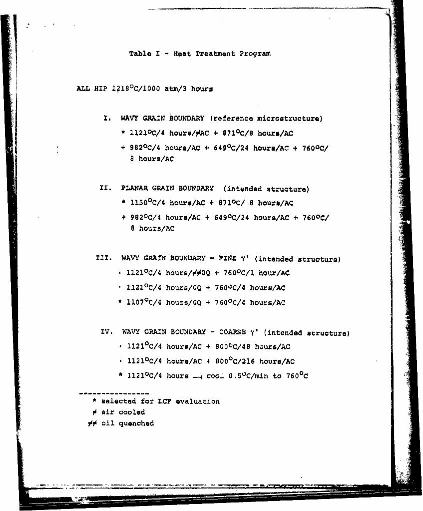
14Table I.- Heat Treatment Program
ALL HIP 1?18 0 C/l000 atm/3 hours
I. WAVY GRAIN BOUNDARY (reference microstructure)
* i121oC/4 hours/#AC + 871 0 C/8 hours/AC
+ 982OC/4 hours/AC + 649 0 C/24 hours/AC + 760oC/8 hours/AC
11. PLANAR GRAIN BOUNDARY (intended structure)
* 11500 C/4 hours/AC + 871OC/ 8 hours/AC
+ 982 0 C/4 hours/AC + 649 0 C/24 hours/AC + 760oC/8 hours/AC
I1I. WAVY GRAIN BOUNDARY - FINE Y' (intended structure)
. 1121°C/4 hours/##OQ + 7600C/1 hour/AC
a 1121°C/4 hours/OQ + 760OC/4 hours/AC
* 1107 0 C/4 hours/OQ + 760OC/4 hours/AC
IV. WAVY GRAIN BOUNDARY - COARSE y' (intended structure). 1121°C/4 hours/AC + 800 0 C/48 hours/AC
0 1121°C/4 hours/AC + 800OC/216 hours/AC
* 1121OC/4 hours -- cool 0,5 0 C/min to 760 0C
* selected for LCF evaluationrSair cooled
@% oil quenched
- FM li*

34
TABLE II
Mode of LCF Crack Initiation and Propagation
Mode of Mode ofTemperature Frequency Alloy Initia- Propaga-°C (OF) Hz tion tion
RT 0.04 Waspaloy I IRT 0.05 L/C Astroloy(I) I I(II') I I
(IV) I I
427(800) 0.05 Waspaloy I IIL/C Ast(I) I IIL/C Ast (I1) 1 IL/C Ast (III) I IIL/C Ast (IV) I II
538(1000) 0.05 L/C Ast (I) I IL/C Ant (II) I I+L/C Ast (I1I) I 1+1L/C Ant (IV) I II
549.(1200) 0.05 Waspaloy I IIL/C Ant (I) I IIL/C Ast (I1) I+IG 1+11L/C Ast (III) IG IL/C Ast (IV) I II+I
0.005 L/C Ast (I) IG II+50%I0.5 L/C Ast (I) I II0.5 L/C Ant (II) I I
760(1400) 0.05 Waspaloy I II+20%IL/C Ast (I) IG II (after
less than1 graindiameter
L/C Ast (I1) IG IL/C Ast (III) IG IL/C Ant (IV) IG II
KEY: I.- stage III - stage IIIG - intergranular