04 radiology in maxillofacial trauma.ppt. new presentation
48
Dr. Ayesha Isani Majeed MCPS, FRCR Assistant Professor & Consultant Department of Radiology Pakistan Institute of Medical Sciences Islamabad Radiology Clinic; Blue Area
-
Upload
jamil-kifayatullah -
Category
Health & Medicine
-
view
113 -
download
2
Transcript of 04 radiology in maxillofacial trauma.ppt. new presentation
Dr. Ayesha Isani MajeedMCPS, FRCRAssistant Professor & ConsultantDepartment of RadiologyPakistan Institute of Medical Sciences
Islamabad Radiology Clinic; Blue Area
This forum is an excellent opportunity to assess the approach to maxillo facial injuries. We have a composite comprising of maxillo facial surgeons, plastic surgeons, and radiologists.
As a radiologist my aim is to give an idea about the input we can give to the clinicians by the various imaging modalities at our disposal.
I would like this discussion to be an interactive one and would appreciate a feedback as to what the clinicians require so that our output as radiologists is fruitful. It has to be a team effort because teams are what win matches not individuals.
1. Plain radiographs in two planes 2. CT3. MRI
The history and physical examination have long been identified as the most important initial steps in the diagnosis of a medical disorder. The clinical evaluation of all trauma patients must be done first, and a through documentation of all components of their injury is necessary in order to enable the correct radiographic examination.
A word about radiation exposureLowest radiation dose x-rayCT 0.4-4.7c Gy (average 2.5c Gy) (skin dose)Gonadal 0.1-0.3 u GyTomography skin dose 6 u Gy
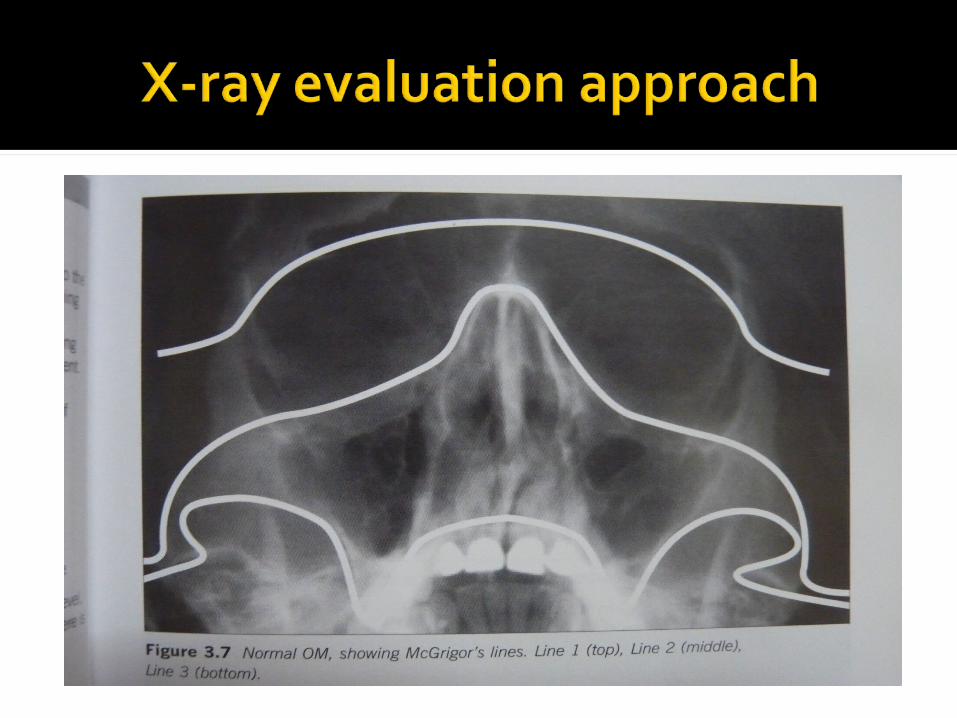
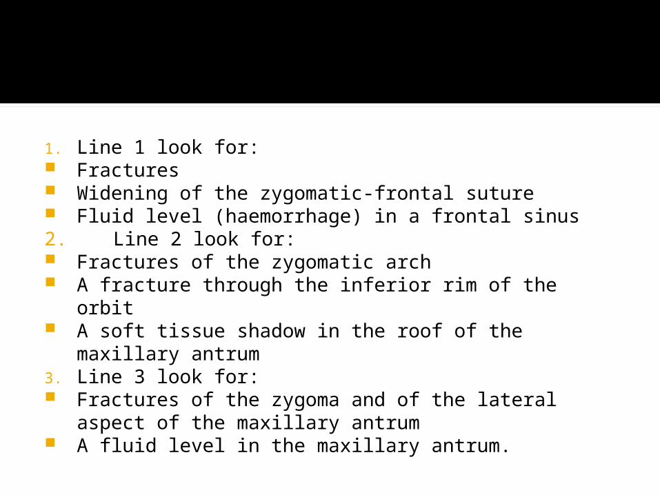
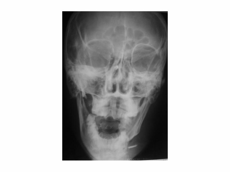
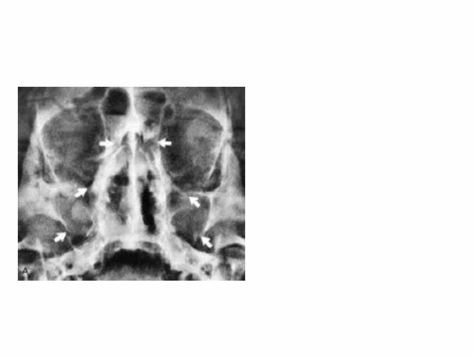
1. Line 1 look for: Fractures Widening of the zygomatic-frontal suture Fluid level (haemorrhage) in a frontal sinus2. Line 2 look for: Fractures of the zygomatic arch A fracture through the inferior rim of the orbit A soft tissue shadow in the roof of the maxillary
antrum3. Line 3 look for: Fractures of the zygoma and of the lateral aspect of
the maxillary antrum A fluid level in the maxillary antrum.
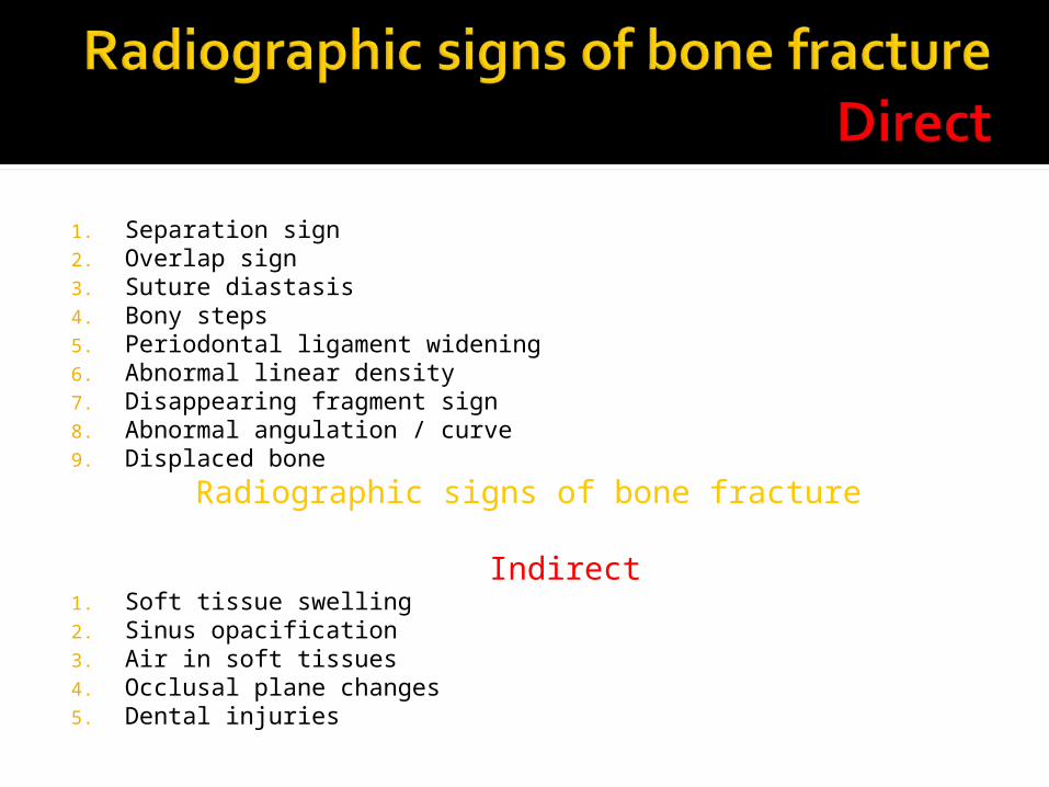
1. Separation sign2. Overlap sign3. Suture diastasis4. Bony steps5. Periodontal ligament widening6. Abnormal linear density7. Disappearing fragment sign8. Abnormal angulation / curve9. Displaced bone
Radiographic signs of bone fracture Indirect
1. Soft tissue swelling2. Sinus opacification3. Air in soft tissues4. Occlusal plane changes5. Dental injuries
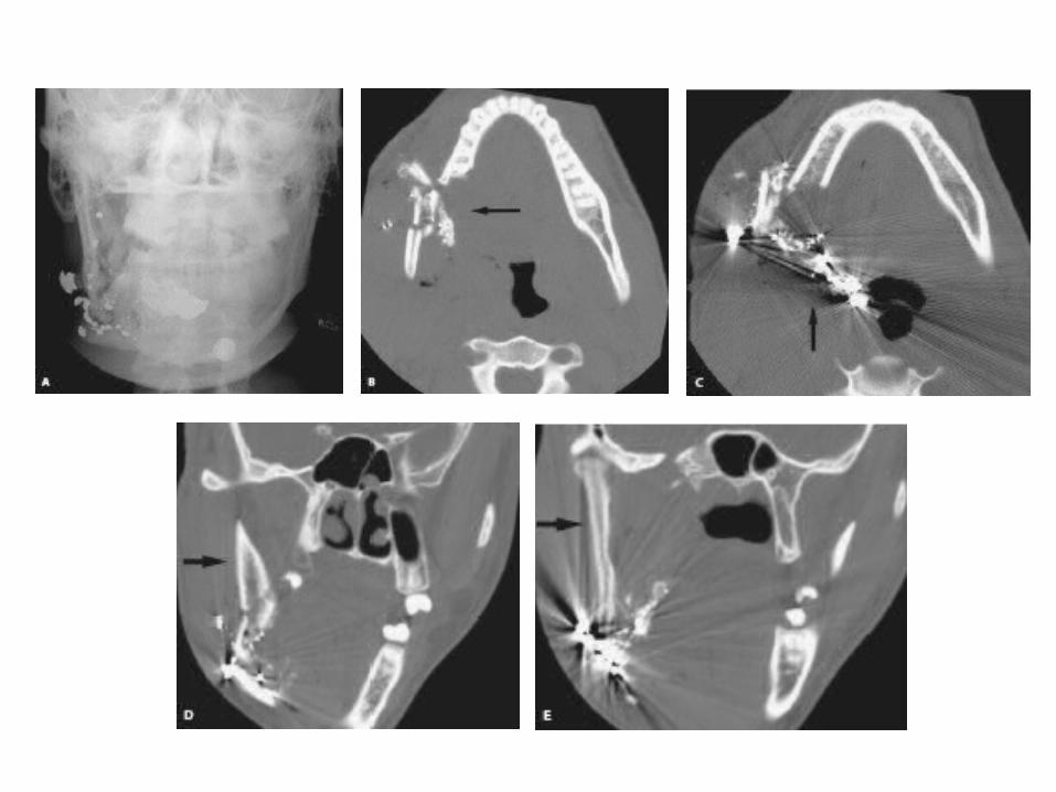
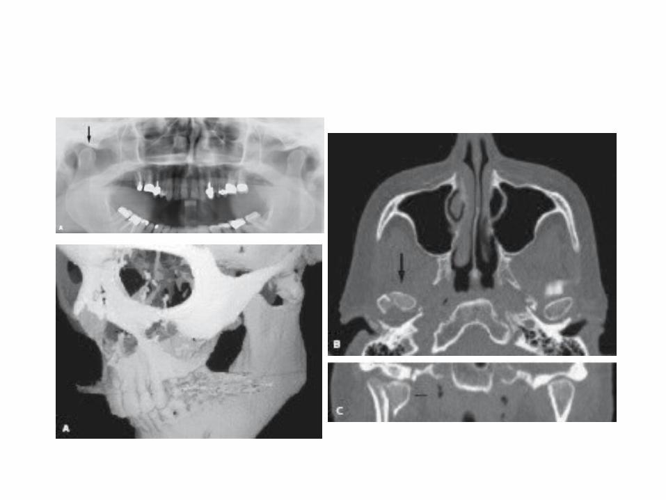
‘Gold standard’ in multi planar evaluation of midface trauma
Little value in: Uncomplicated mandibular fractures Le Fort I level fractures
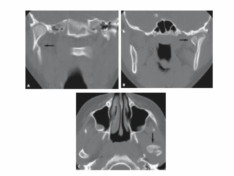
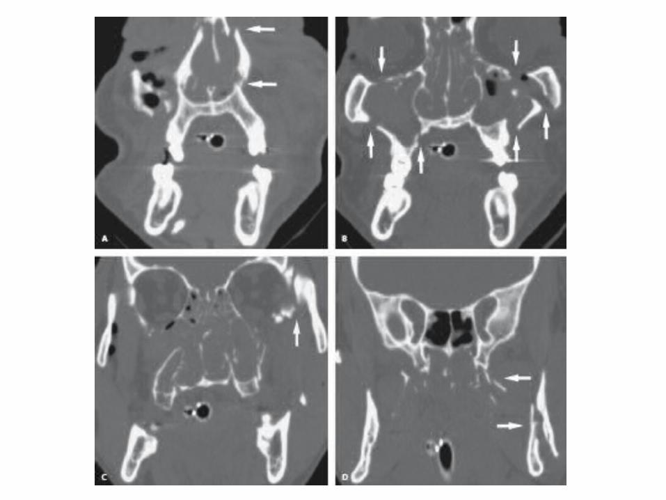
CT’s can be evaluated by a concept of a series of horizontal, coronal, and saggital struts or buttresses. These can be used to evaluate the ct images of patients with facial trauma.
Horizontal plane struts Superior Orbital roof Middle Orbital floor Inferior Hard palate Saggital plane struts Midline Perpendicular plate of ethmoid Parasaggital Medial orbital walls Lateral Lateral orbital walls Coronal plane struts Anterior Anterior wall of frontal sinus Posterior Posterior wall of maxillary antra
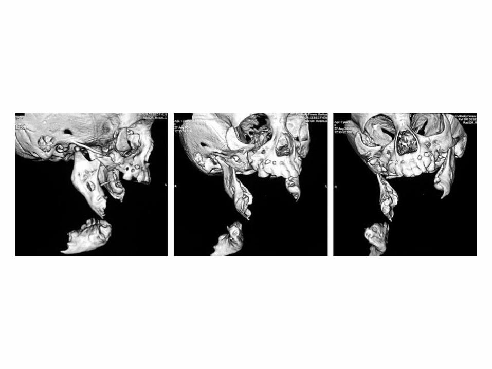
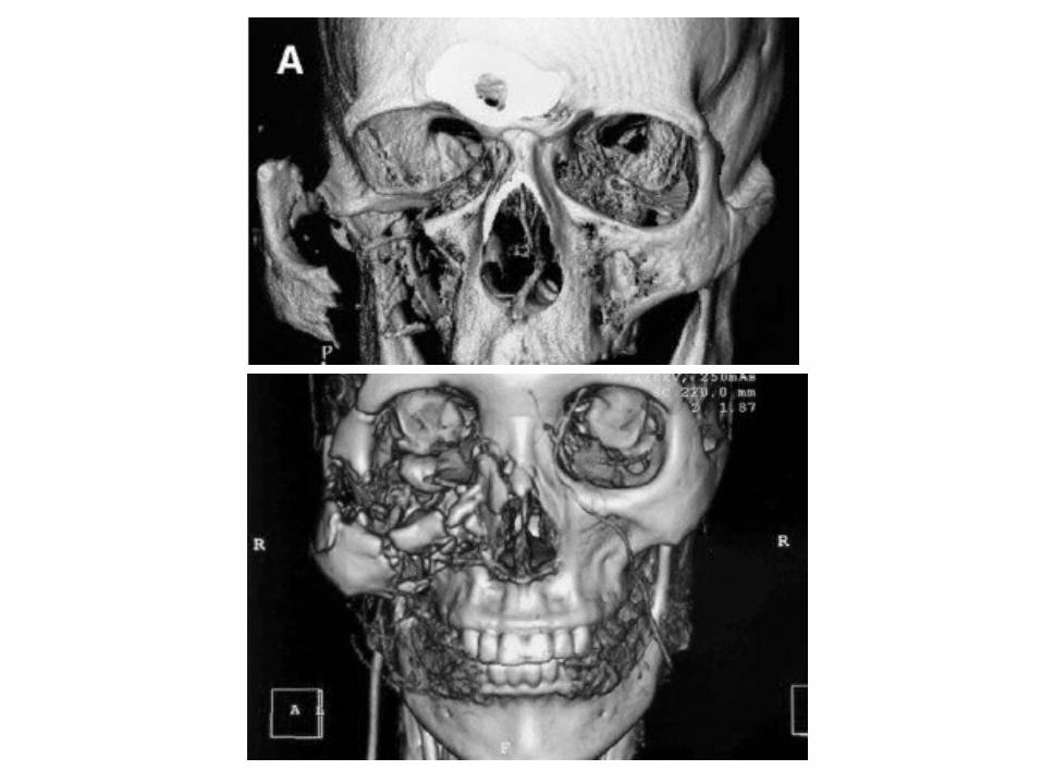
No extra information beyond plain CT Better 3D assessment for some
surgeons Easier fracture localization Valuable in planning information; esp
in panfacial trauma Patient counseling & education
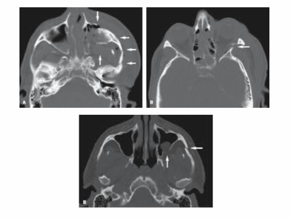
Be wary of false bone fenestrations
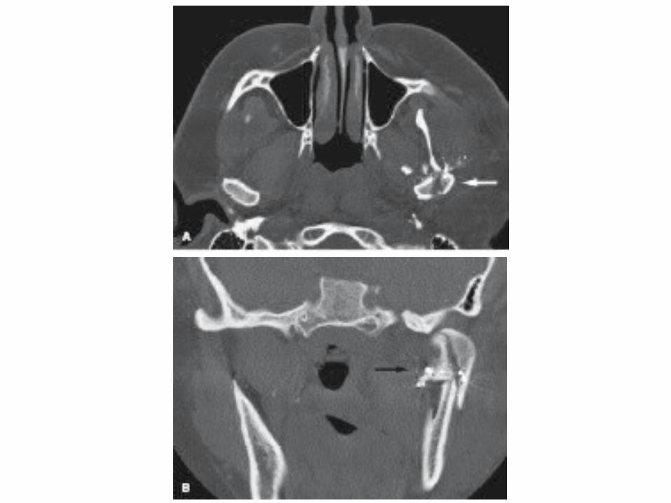
Mandibular fractures: Mandibular fractures as a
group, are best evaluated and diagnosed with plain films + polytomographs. The mandibular series involves
a)A right and left oblique viewb)PA viewc) Lateral skull filmd)Towne’s view combined with a pantomogram images of a) subcondyler d) angle b) coronoid e) body fractures c) ramus f) symphysis and
alveolar fractures

OPGPA FaceReverse Towne’s viewTranscranial arthrogramsCT
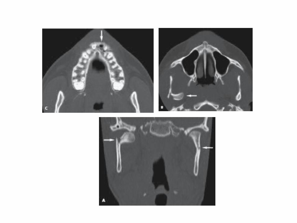
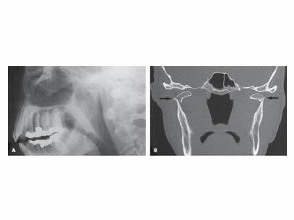
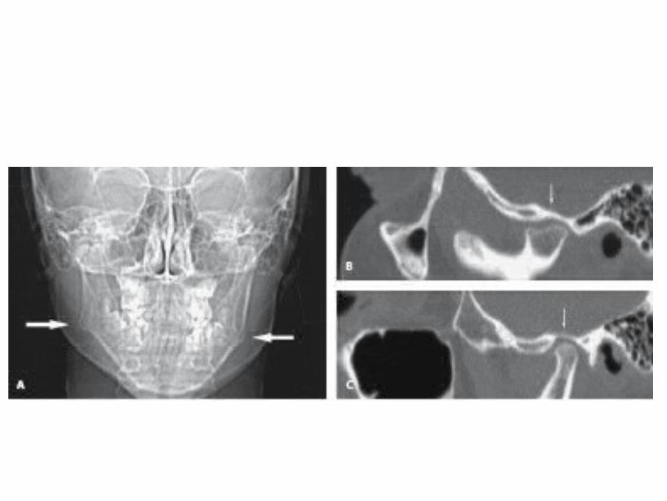
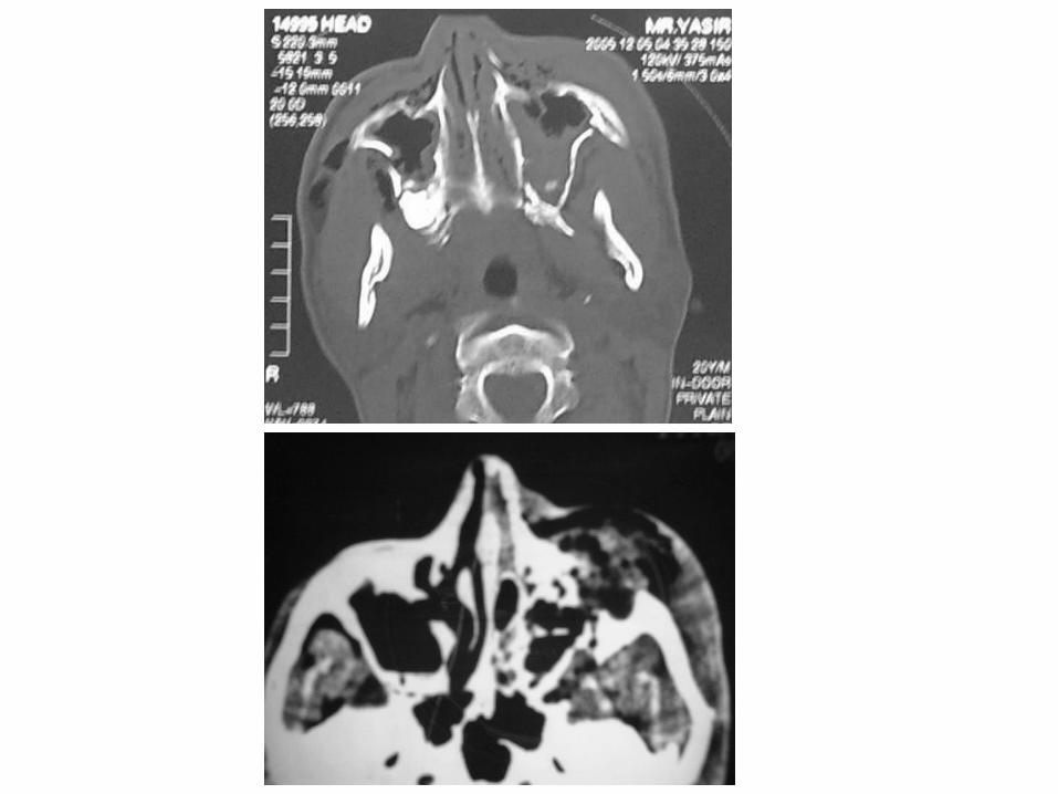
See beyond swelling Occipitomental projections Water’s view Occipitofrontal projections Submentovertex view for arch
CT images best
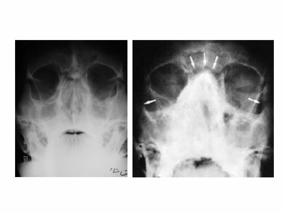
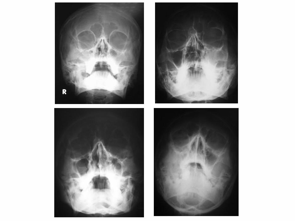
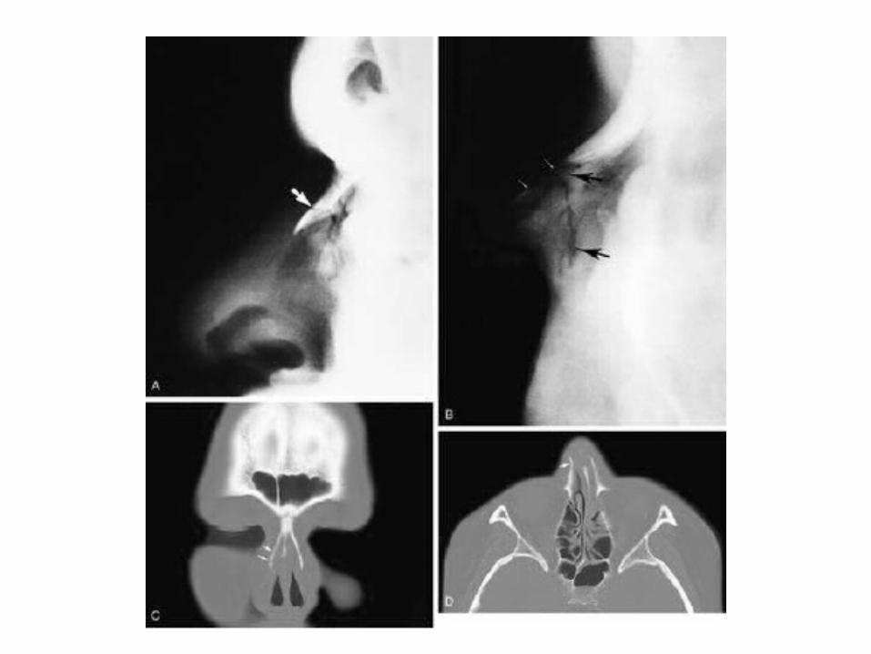
Lateral view of faceOccipitomental projection
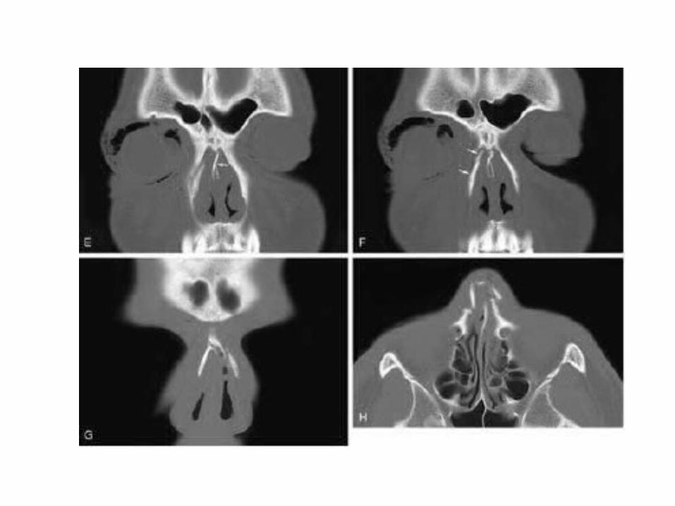
OM view; ‘hanging drop’; little information
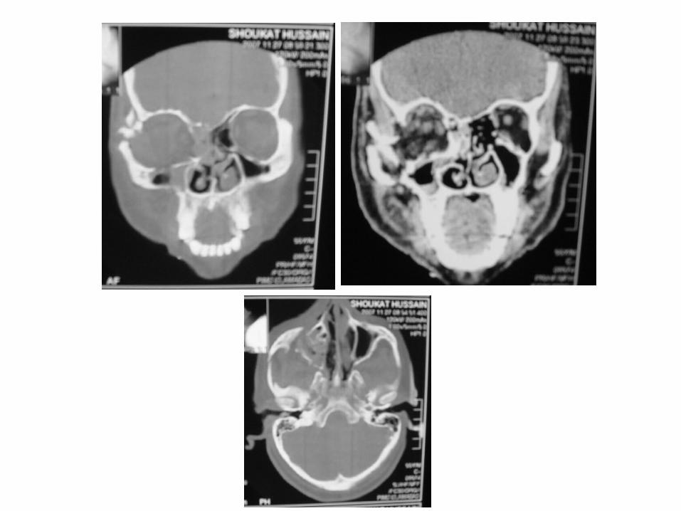
CT in all three planes; extremely valuable Floor; Coronal & sagittal sections Roof; All three planes Lateral & medial walls; Axial & coronal
sections
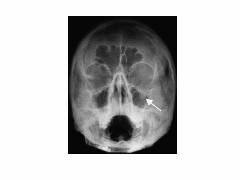
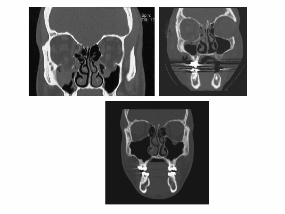
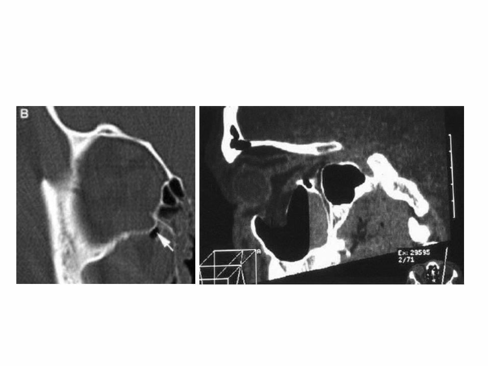
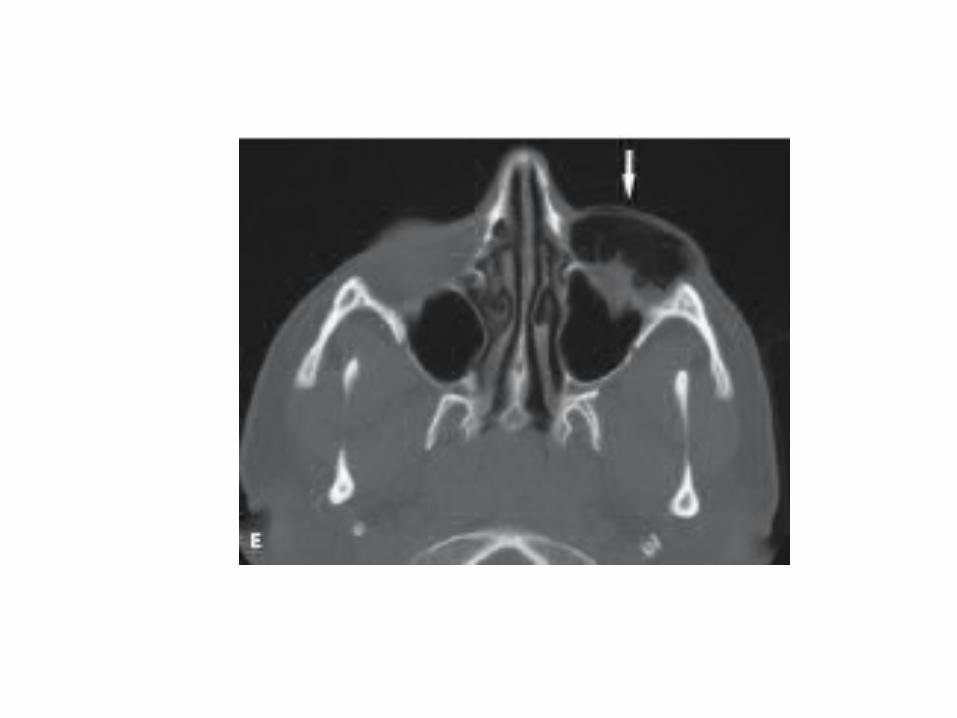
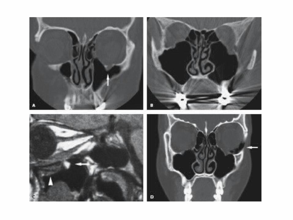
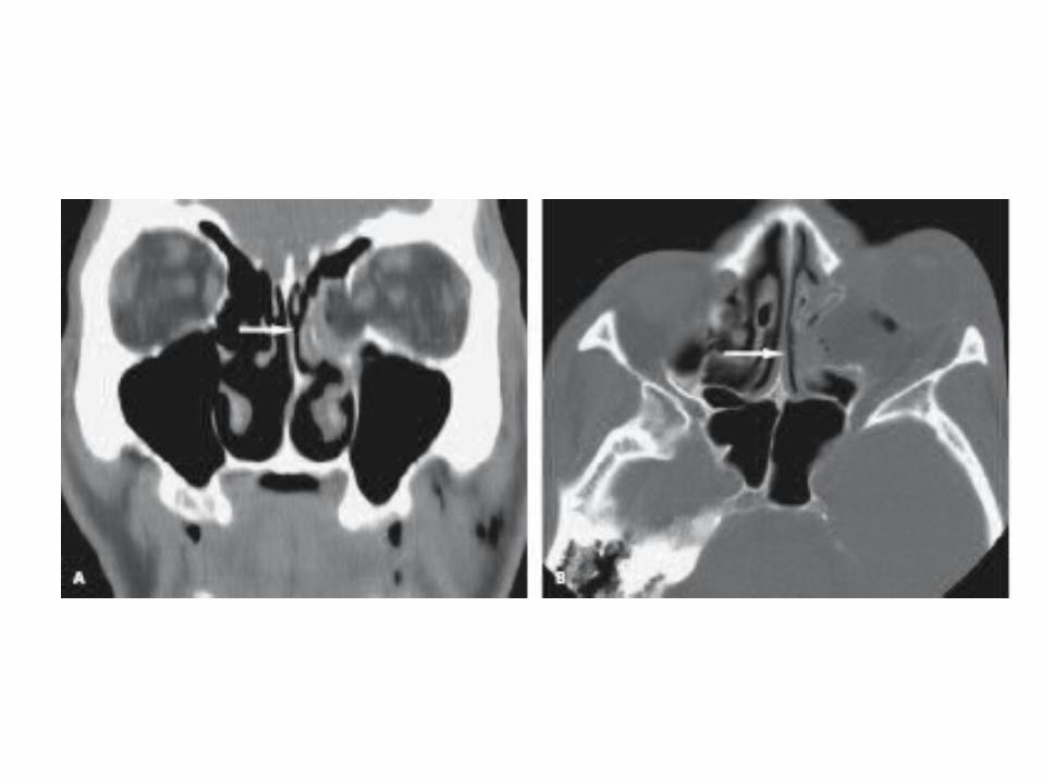
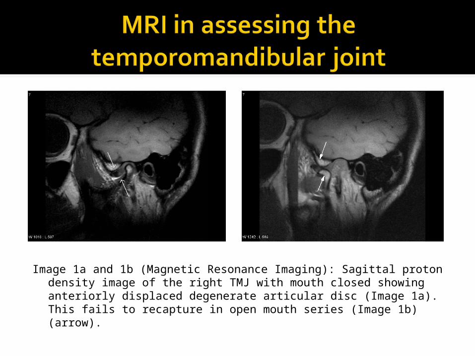
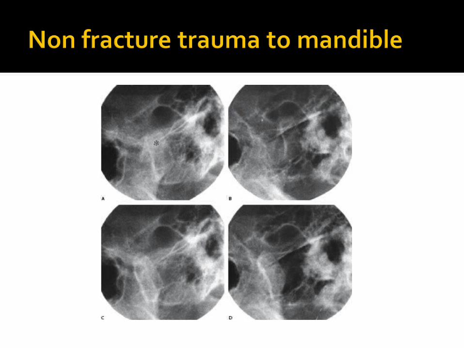
Image 1a and 1b (Magnetic Resonance Imaging): Sagittal proton density image of the right TMJ with mouth closed showing anteriorly displaced degenerate articular disc (Image 1a). This fails to recapture in open mouth series (Image 1b) (arrow).
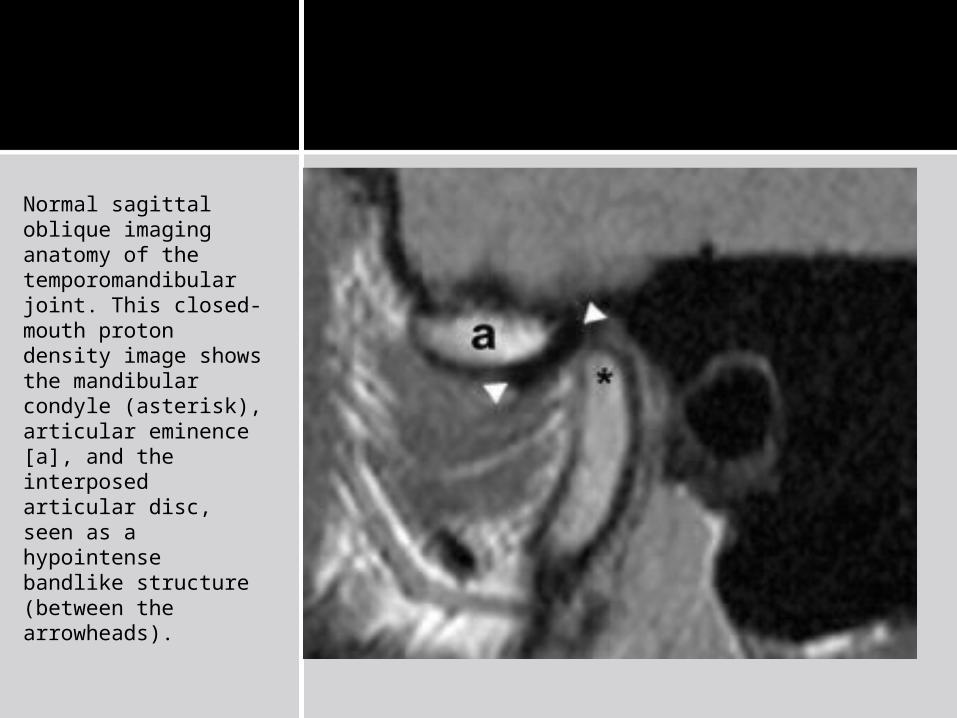
Normal sagittal oblique imaging anatomy of the temporomandibular joint. This closed-mouth proton density image shows the mandibular condyle (asterisk), articular eminence [a], and the interposed articular disc, seen as a hypointense bandlike structure (between the arrowheads).
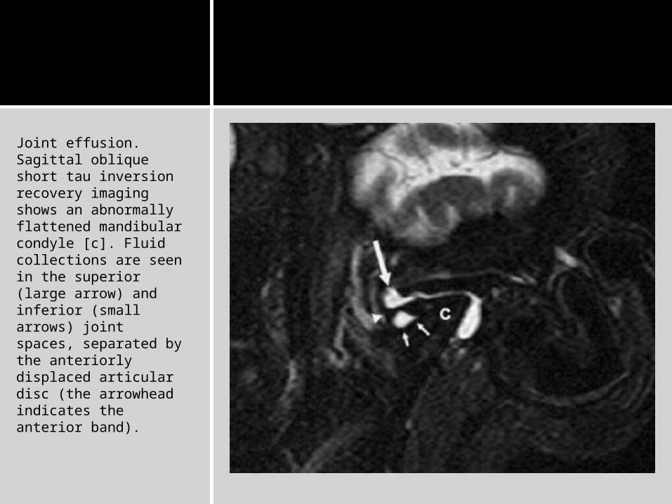
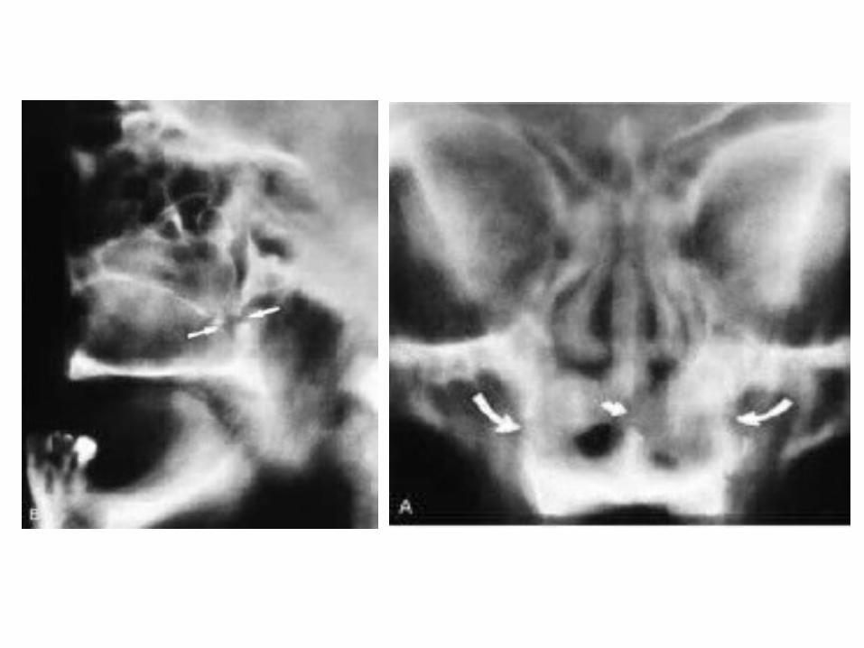
Joint effusion. Sagittal oblique short tau inversion recovery imaging shows an abnormally flattened mandibular condyle [c]. Fluid collections are seen in the superior (large arrow) and inferior (small arrows) joint spaces, separated by the anteriorly displaced articular disc (the arrowhead indicates the anterior band).

Do x rays only if necessary Digital x rays are better Correct angulation is important CT has become increasingly popular;
more so with increasing employment of ORIF (open reduction internal fixation) in facial fractures; 3D is an invaluable tool for planning treatment
MRI’s role is being defined