04 - Branch Connections
24
CAU Express 2013 1 Branch Connections David Diehl © Intergraph 2013 CAESAR II Improvements in Modeling and Evaluating Branch Connections © Intergraph 2013 Current B31.3 Appendix D Tee flexibility is set to 1.0 – no flexibility! Typically, the in-plane stress intensification factor (SIF or i) is less than the out-plane SIF: ൌ 3 4 ൗ 1 4 ൗ A note on reduced tees
Transcript of 04 - Branch Connections
CAU Express 2013 1
Branch ConnectionsDavid Diehl
© Intergraph 2013
CAESAR II
Improvements in Modeling and Evaluating Branch Connections
© Intergraph 2013
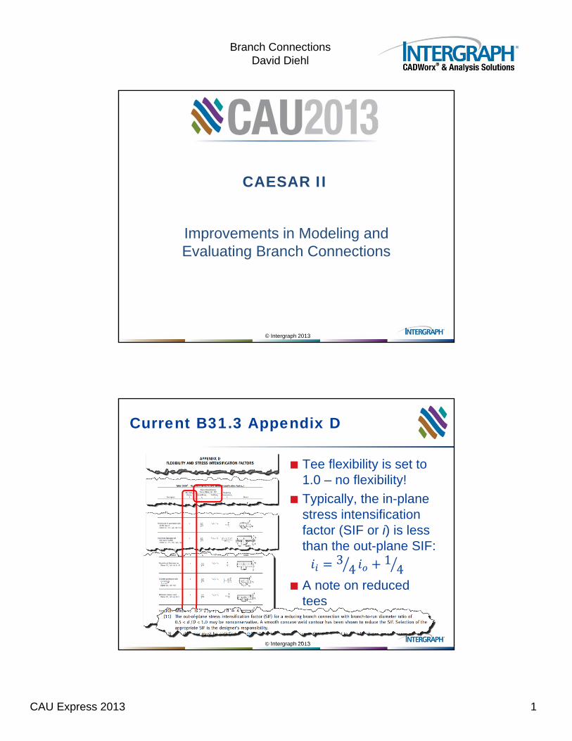
Current B31.3 Appendix D
Tee flexibility is set to 1.0 – no flexibility!
Typically, the in-plane stress intensification factor (SIF or i) is less than the out-plane SIF:
34
14
A note on reduced tees
CAU Express 2013 2
Branch ConnectionsDavid Diehl
© Intergraph 2013
Introduction
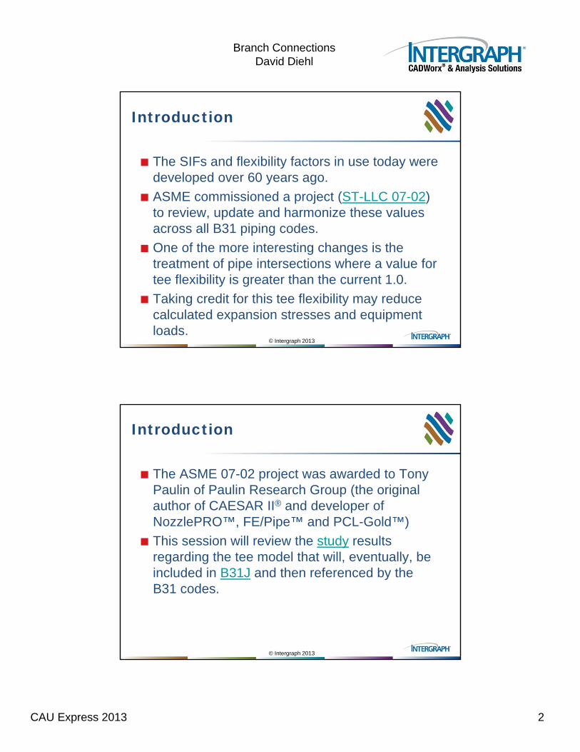
The SIFs and flexibility factors in use today were developed over 60 years ago.
ASME commissioned a project (ST-LLC 07-02) to review, update and harmonize these values across all B31 piping codes.
One of the more interesting changes is the treatment of pipe intersections where a value for tee flexibility is greater than the current 1.0.
Taking credit for this tee flexibility may reduce calculated expansion stresses and equipment loads.
© Intergraph 2013
Introduction
The ASME 07-02 project was awarded to Tony Paulin of Paulin Research Group (the original author of CAESAR II® and developer of NozzlePRO™, FE/Pipe™ and PCL-Gold™)
This session will review the study results regarding the tee model that will, eventually, be included in B31J and then referenced by the B31 codes.
CAU Express 2013 3
Branch ConnectionsDavid Diehl
© Intergraph 2013
Introduction
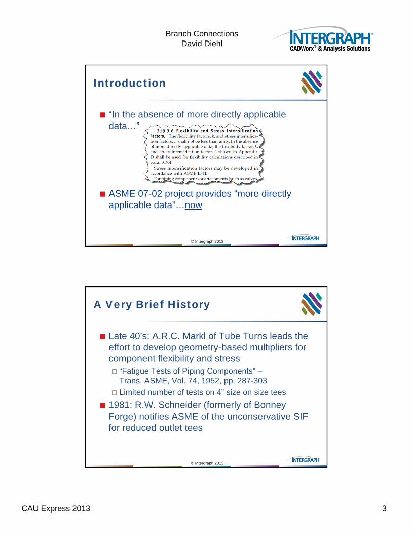
“In the absence of more directly applicable data…”
ASME 07-02 project provides “more directly applicable data”…now
© Intergraph 2013
A Very Brief History
Late 40’s: A.R.C. Markl of Tube Turns leads the effort to develop geometry-based multipliers for component flexibility and stress “Fatigue Tests of Piping Components” –
Trans. ASME, Vol. 74, 1952, pp. 287-303
Limited number of tests on 4” size on size tees
1981: R.W. Schneider (formerly of BonneyForge) notifies ASME of the unconservative SIF for reduced outlet tees
CAU Express 2013 4
Branch ConnectionsDavid Diehl
© Intergraph 2013
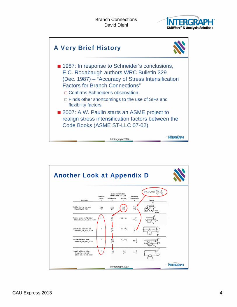
A Very Brief History
1987: In response to Schneider’s conclusions, E.C. Rodabaugh authors WRC Bulletin 329 (Dec. 1987) – “Accuracy of Stress Intensification Factors for Branch Connections” Confirms Schneider’s observation
Finds other shortcomings to the use of SIFs and flexibility factors
2007: A.W. Paulin starts an ASME project to realign stress intensification factors between the Code Books (ASME ST-LLC 07-02).
© Intergraph 2013
Another Look at Appendix D
CAU Express 2013 5
Branch ConnectionsDavid Diehl
© Intergraph 2013
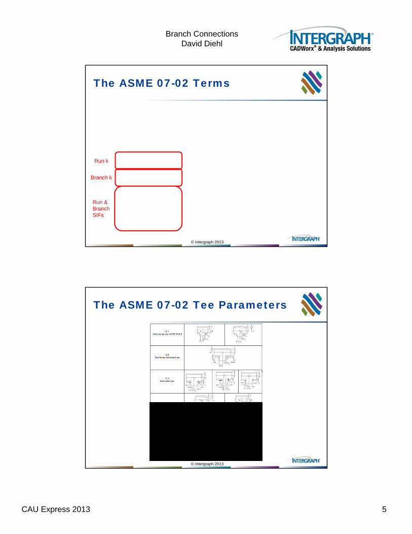
The ASME 07-02 Terms
Run k
Branch k
Run & Branch SIFs
© Intergraph 2013
The ASME 07-02 Tee Parameters
CAU Express 2013 6
Branch ConnectionsDavid Diehl
© Intergraph 2013
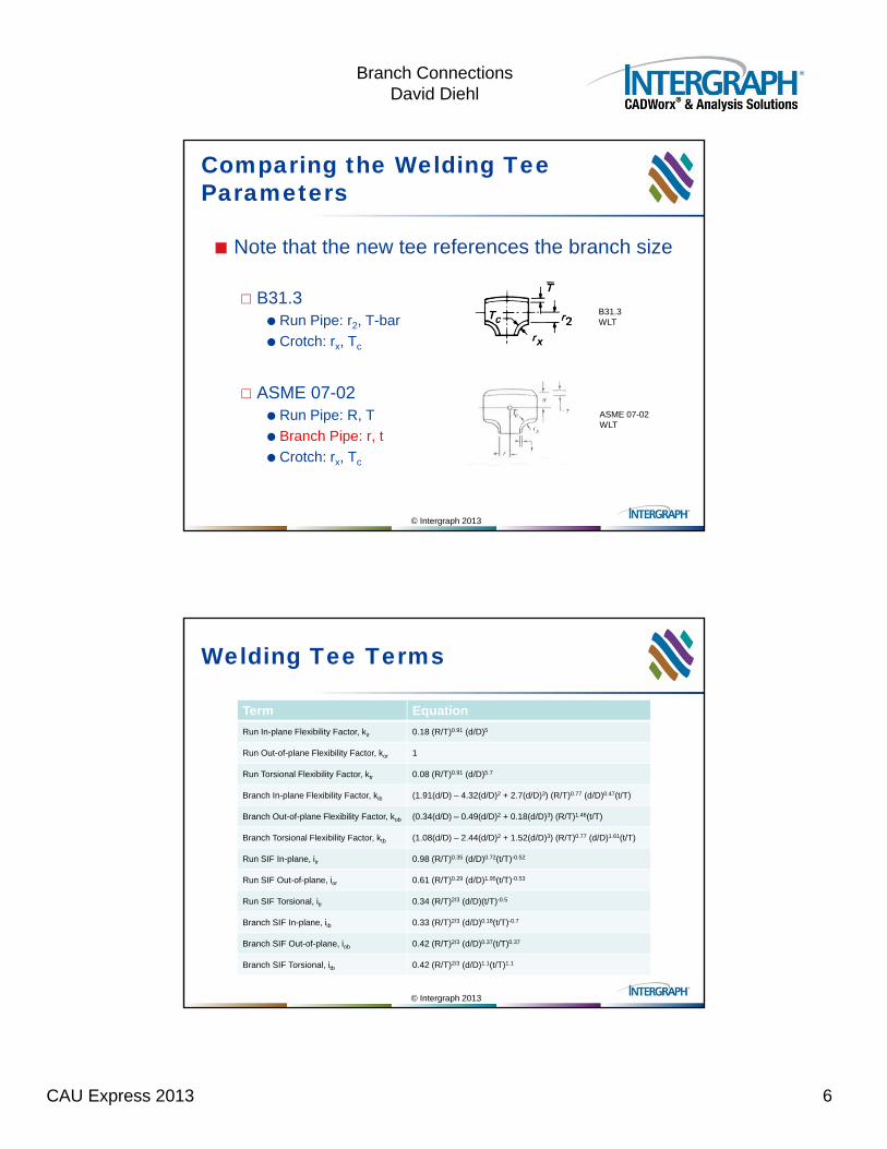
Comparing the Welding Tee Parameters
Note that the new tee references the branch size
B31.3 Run Pipe: r2, T-bar
Crotch: rx, Tc
ASME 07-02 Run Pipe: R, T
Branch Pipe: r, t
Crotch: rx, Tc
B31.3 WLT
ASME 07-02 WLT
© Intergraph 2013
Welding Tee Terms
Term Equation
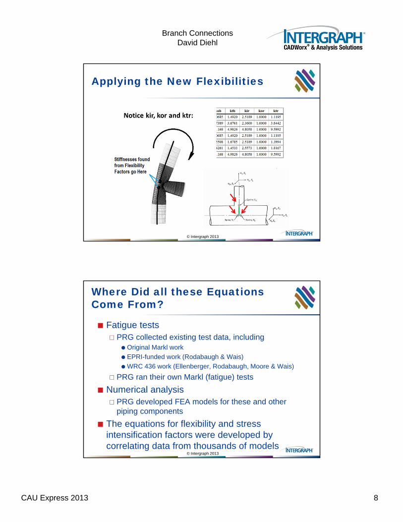
Run In-plane Flexibility Factor, kir 0.18 (R/T)0.91 (d/D)5
Run Out-of-plane Flexibility Factor, kor 1
Run Torsional Flexibility Factor, ktr 0.08 (R/T)0.91 (d/D)5.7
Branch In-plane Flexibility Factor, kib (1.91(d/D) – 4.32(d/D)2 + 2.7(d/D)3) (R/T)0.77 (d/D)0.47(t/T)
Branch Out-of-plane Flexibility Factor, kob (0.34(d/D) – 0.49(d/D)2 + 0.18(d/D)3) (R/T)1.46(t/T)
Branch Torsional Flexibility Factor, ktb (1.08(d/D) – 2.44(d/D)2 + 1.52(d/D)3) (R/T)0.77 (d/D)1.61(t/T)
Run SIF In-plane, iir 0.98 (R/T)0.35 (d/D)0.72(t/T)-0.52
Run SIF Out-of-plane, ior 0.61 (R/T)0.29 (d/D)1.95(t/T)-0.53
Run SIF Torsional, itr 0.34 (R/T)2/3 (d/D)(t/T)-0.5
Branch SIF In-plane, iib 0.33 (R/T)2/3 (d/D)0.18(t/T)-0.7
Branch SIF Out-of-plane, iob 0.42 (R/T)2/3 (d/D)0.37(t/T)0.37
Branch SIF Torsional, itb 0.42 (R/T)2/3 (d/D)1.1(t/T)1.1
CAU Express 2013 7
Branch ConnectionsDavid Diehl
© Intergraph 2013
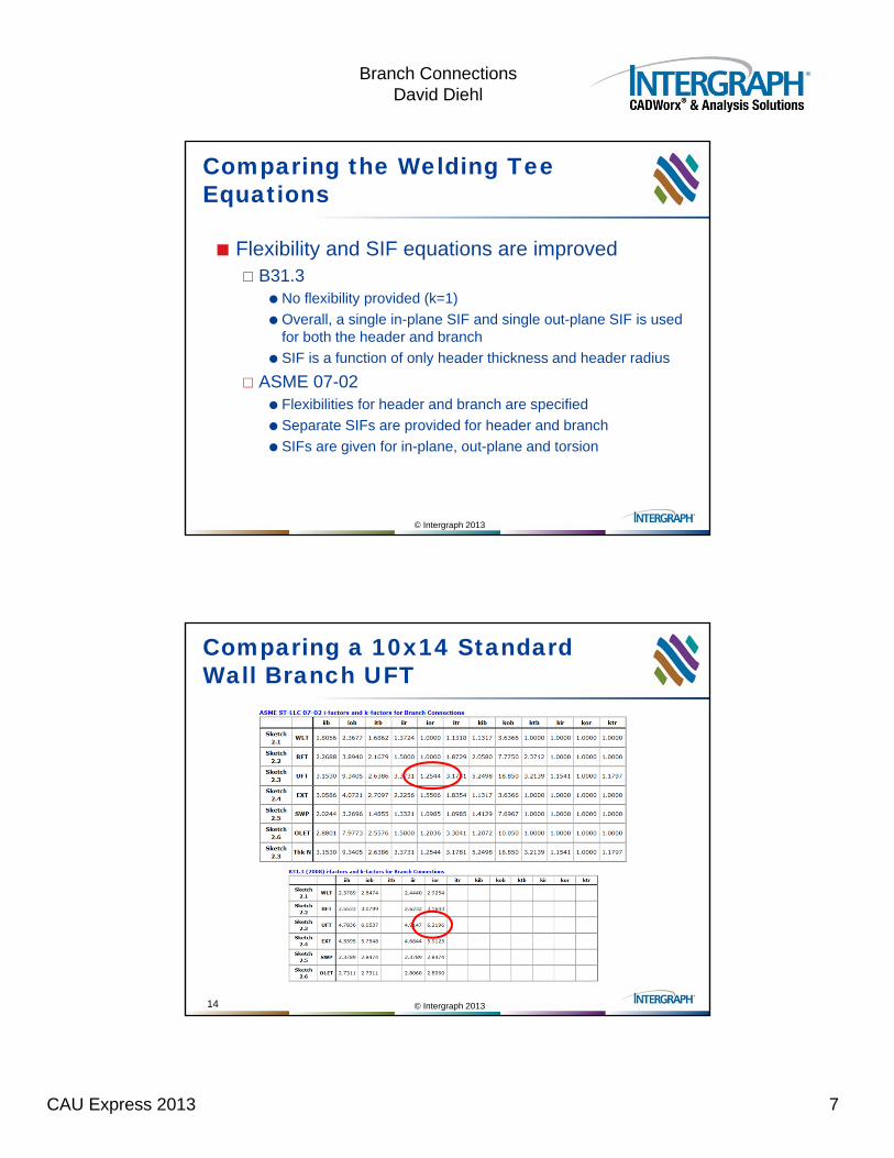
Comparing the Welding Tee Equations
Flexibility and SIF equations are improved B31.3
No flexibility provided (k=1)
Overall, a single in-plane SIF and single out-plane SIF is used for both the header and branch
SIF is a function of only header thickness and header radius
ASME 07-02 Flexibilities for header and branch are specified
Separate SIFs are provided for header and branch
SIFs are given for in-plane, out-plane and torsion
© Intergraph 2013
Comparing a 10x14 Standard Wall Branch UFT
14
CAU Express 2013 8
Branch ConnectionsDavid Diehl
© Intergraph 2013
Applying the New Flexibilities
© Intergraph 2013
Where Did all these Equations Come From?
Fatigue tests PRG collected existing test data, including
Original Markl work
EPRI-funded work (Rodabaugh & Wais)
WRC 436 work (Ellenberger, Rodabaugh, Moore & Wais)
PRG ran their own Markl (fatigue) tests
Numerical analysis PRG developed FEA models for these and other
piping components
The equations for flexibility and stress intensification factors were developed by correlating data from thousands of models
CAU Express 2013 9
Branch ConnectionsDavid Diehl
© Intergraph 2013
What’s Wrong with What We Have Now?
B31 Appendix D has been in use for many years and has produced safe piping systems
Fortunately, the current inaccuracies have little impact in systems with low cycles
Unfortunately, ignoring intersection flexibility has inflated strain-based loads on equipment leading to more expensive layout and support “solutions”
The biggest issues: The d to D ratio (reduced outlets)
The ii / io reversal (termed “silly” in WRC 329)
Centerline-to-wall phantom branch flexibility
© Intergraph 2013
WRC 329 Identifies Several Problems with Existing Codes
Welding Research Council Bulletin 329 –Accuracy of Stress Intensification Factors for Branch Connections by E.C. Rodabaugh p.9 “… using i = 1.0 for Mt on full size outlet branch connections
can lead to inaccuracies far greater than the Mob inconsistency.”
p.12 “We would rate the relative complexity of i-factors for pipe, elbows and branch connections by the ratios of 1:5:500. … [readers] will not find any simple answers in this report.”
p.13 “Extruded outlets are somewhat related to ANSI B16.9 tees in that extruded outlets, like B16.9 tees, may vary significantly between manufacturers.”
CAU Express 2013 10
Branch ConnectionsDavid Diehl
© Intergraph 2013
WRC 329 Identifies Several Problems with Existing Codes
p.21 “[B31.3 itb=1] is nonconservative by a factor of 2.7 … and might be nonconservative by a factor of 12 or more.”
p. 22 “For run moments on branch connections with small r/R, both intuition and Ref. 26 data indicate that the B31.3 relationship ii = 0.75io + 0.25 is at best, reversed in relative magnitude of iir and ior, … and in effect, [the] Code requirements are obviously silly.”
p.28 “The Mob tests indicate that there is a peak somewhere around 0.75.” [d/D=0.75]
p.29 “.. we do not necessarily achieve greater accuracy in Code evaluations by using more accurate i-factors unless more accurate k-factors are also used.”
© Intergraph 2013
WRC 329 Identifies Several Problems with Existing Codes
p.32-33 “… delete the use of ii = 0.75io + 0.25 for branch connections/tees, … [it] gives the wrong relative magnitude for Mor versus Mir, [and] it underestimates the difference between Mob and Mib for r/R between about 0.3 and 0.95 and perhaps over-estimates the difference for r/R below 0.2 and for r/R = 1.0.”
p.33 “For branch connections with r2 (outer fillet radius) provided, use iib/2.”
p.37 “[limits on the inside radius of the branch connection are] dropped because moment fatigue tests and theory indicate that the inside corner radius is not a critical consideration.” … for external loads (not pressure cycling)
CAU Express 2013 11
Branch ConnectionsDavid Diehl
© Intergraph 2013
Addressing the WRC 329 Findings
The new flexibility and stress intensification factors set in ASME 07-02 resolve many of the problems listed here
But let’s return to one: p.29 “.. we do not necessarily achieve greater
accuracy in Code evaluations by using more accurate i-factors unless more accurate k-factors are also used.”
© Intergraph 2013
ASME 07-02 Flexibility Factors
Using the term “flexibility factor” for tees Bends have long used a similar term – a bend with an
arc length of “L” and a flexibility factor of “x” will rotate the same amount with a given moment as a straight pipe of length x*L
A tee with a flexibility factor of “y” will provide the same flexibility as adding a straight pipe of length y*OD
With this reference, you can start to predict the effects of this change
CAU Express 2013 12
Branch ConnectionsDavid Diehl
© Intergraph 2013
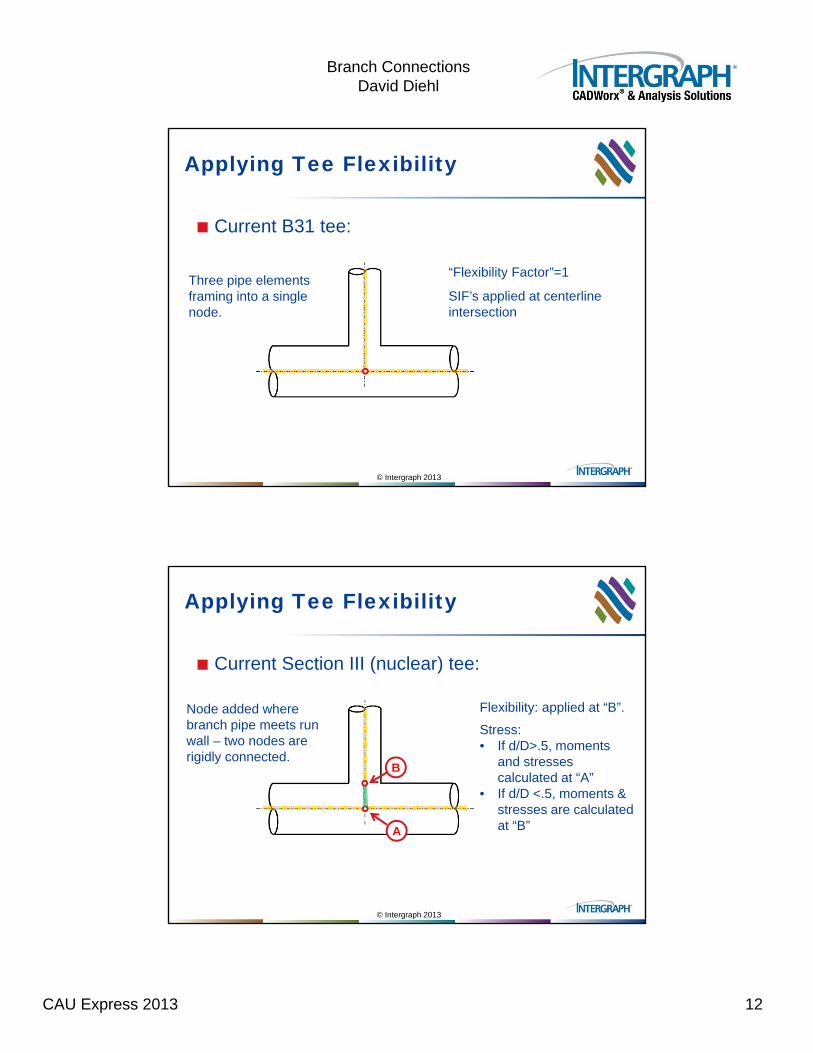
Applying Tee Flexibility
Current B31 tee:
Three pipe elements framing into a single node.
“Flexibility Factor”=1
SIF’s applied at centerline intersection
© Intergraph 2013
Applying Tee Flexibility
Current Section III (nuclear) tee:
Node added where branch pipe meets run wall – two nodes are rigidly connected.
B
A
Flexibility: applied at “B”.
Stress: • If d/D>.5, moments
and stresses calculated at “A”
• If d/D <.5, moments & stresses are calculated at “B”
CAU Express 2013 13
Branch ConnectionsDavid Diehl
© Intergraph 2013
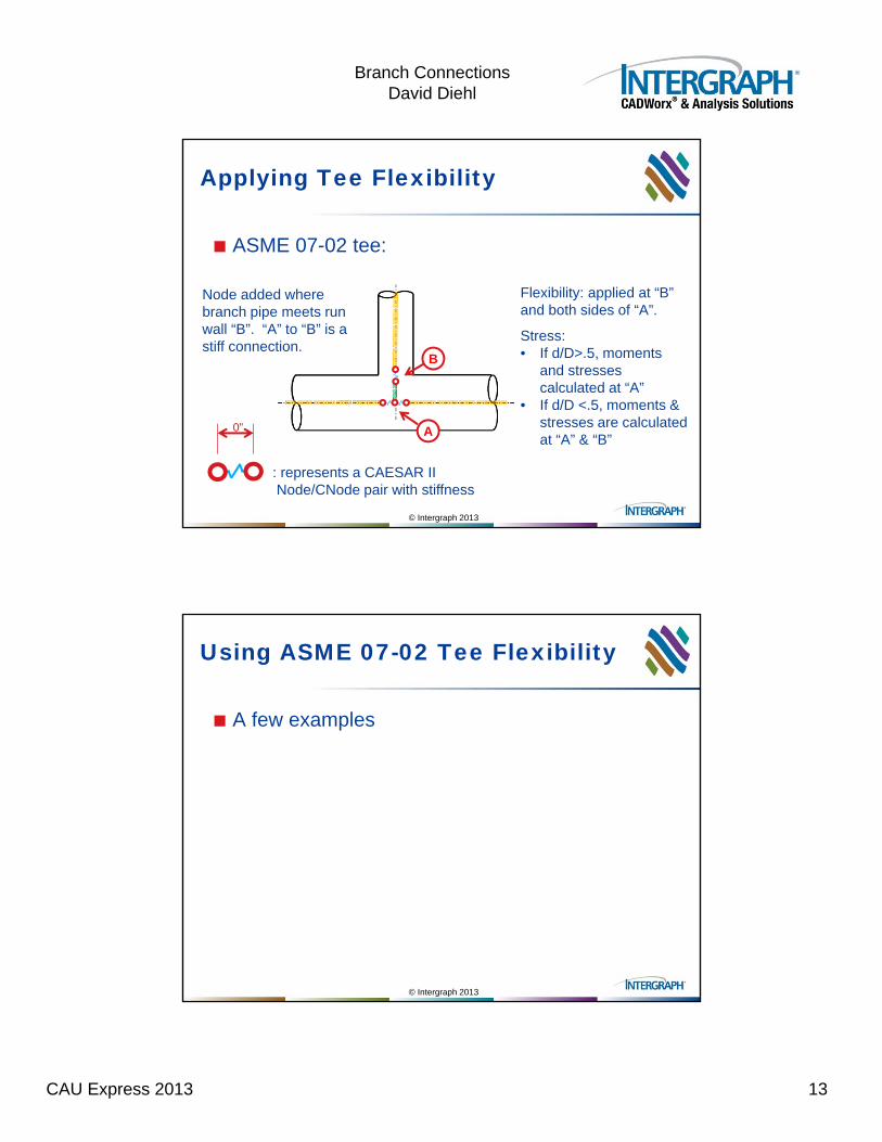
Applying Tee Flexibility
ASME 07-02 tee:
Node added where branch pipe meets run wall “B”. “A” to “B” is a stiff connection.
B
A
Flexibility: applied at “B” and both sides of “A”.
Stress: • If d/D>.5, moments
and stresses calculated at “A”
• If d/D <.5, moments & stresses are calculated at “A” & “B”
: represents a CAESAR IINode/CNode pair with stiffness
0”
© Intergraph 2013
Using ASME 07-02 Tee Flexibility
A few examples
CAU Express 2013 14
Branch ConnectionsDavid Diehl
© Intergraph 201327
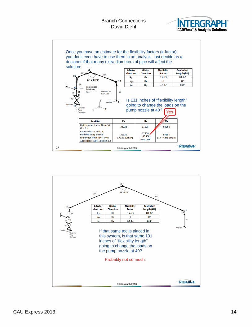
Once you have an estimate for the flexibility factors (k-factor), you don’t even have to use them in an analysis, just decide as a designer if that many extra diameters of pipe will affect the solution:
Is 131 inches of “flexibility length” going to change the loads on the pump nozzle at 40? Yes
© Intergraph 201328
If that same tee is placed in this system, is that same 131 inches of “flexibility length” going to change the loads on the pump nozzle at 40?
Probably not so much.
CAU Express 2013 15
Branch ConnectionsDavid Diehl
© Intergraph 2013
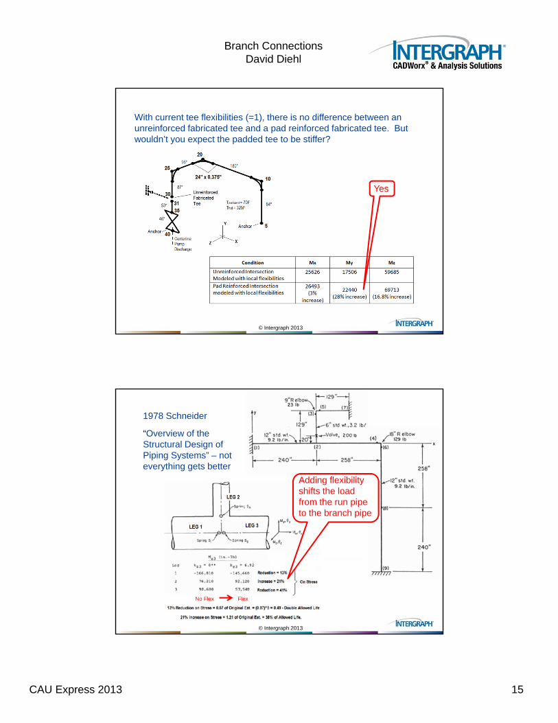
With current tee flexibilities (=1), there is no difference between an unreinforced fabricated tee and a pad reinforced fabricated tee. But wouldn’t you expect the padded tee to be stiffer?
Yes
© Intergraph 2013
1978 Schneider
“Overview of the Structural Design of Piping Systems” – not everything gets better
Adding flexibility shifts the load from the run pipe to the branch pipe
No Flex Flex
CAU Express 2013 16
Branch ConnectionsDavid Diehl
© Intergraph 2013
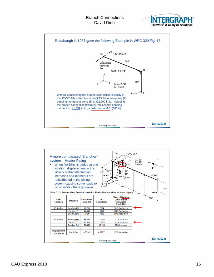
Rodabaugh in 1987 gave the following Example in WRC 329 Fig. 15:
Without considering the branch connection flexibility of the 12x30” fabricated tee at point 15 the out-of-plane (Z) bending moment at point 15 is 372,000 in.lb. Including the branch connection flexibility reduces the bending moment to 41,832 in.lb., a reduction of 8.8. (880%)
© Intergraph 2013
A more complicated (3 anchor) system – Heater Piping• When flexibility is added at one
location, displacement in the vicinity of that intersection increases and moments are redistributed in the piping system causing some loads to go up while others go down
CAU Express 2013 17
Branch ConnectionsDavid Diehl
© Intergraph 2013
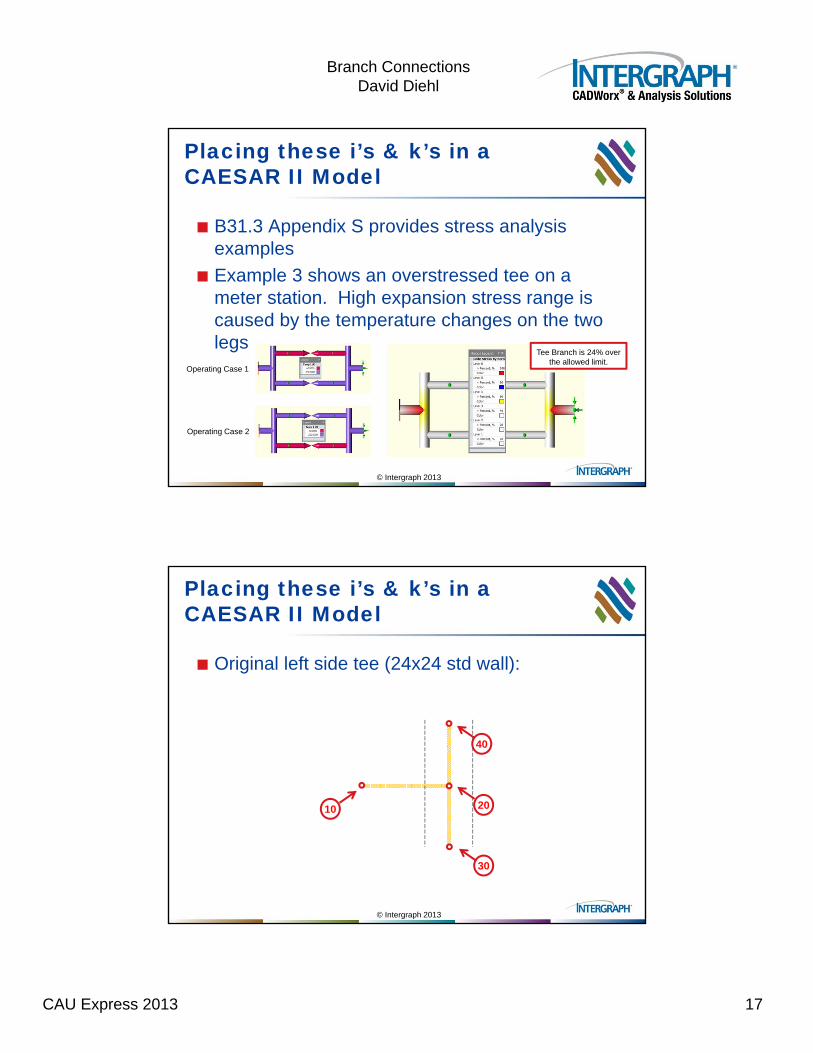
Placing these i’s & k’s in a CAESAR II Model
B31.3 Appendix S provides stress analysis examples
Example 3 shows an overstressed tee on a meter station. High expansion stress range is caused by the temperature changes on the two legs
Operating Case 1
Operating Case 2
Tee Branch is 24% over the allowed limit.
© Intergraph 2013
Placing these i’s & k’s in a CAESAR II Model
Original left side tee (24x24 std wall):
10
40
20
30
CAU Express 2013 18
Branch ConnectionsDavid Diehl
© Intergraph 2013
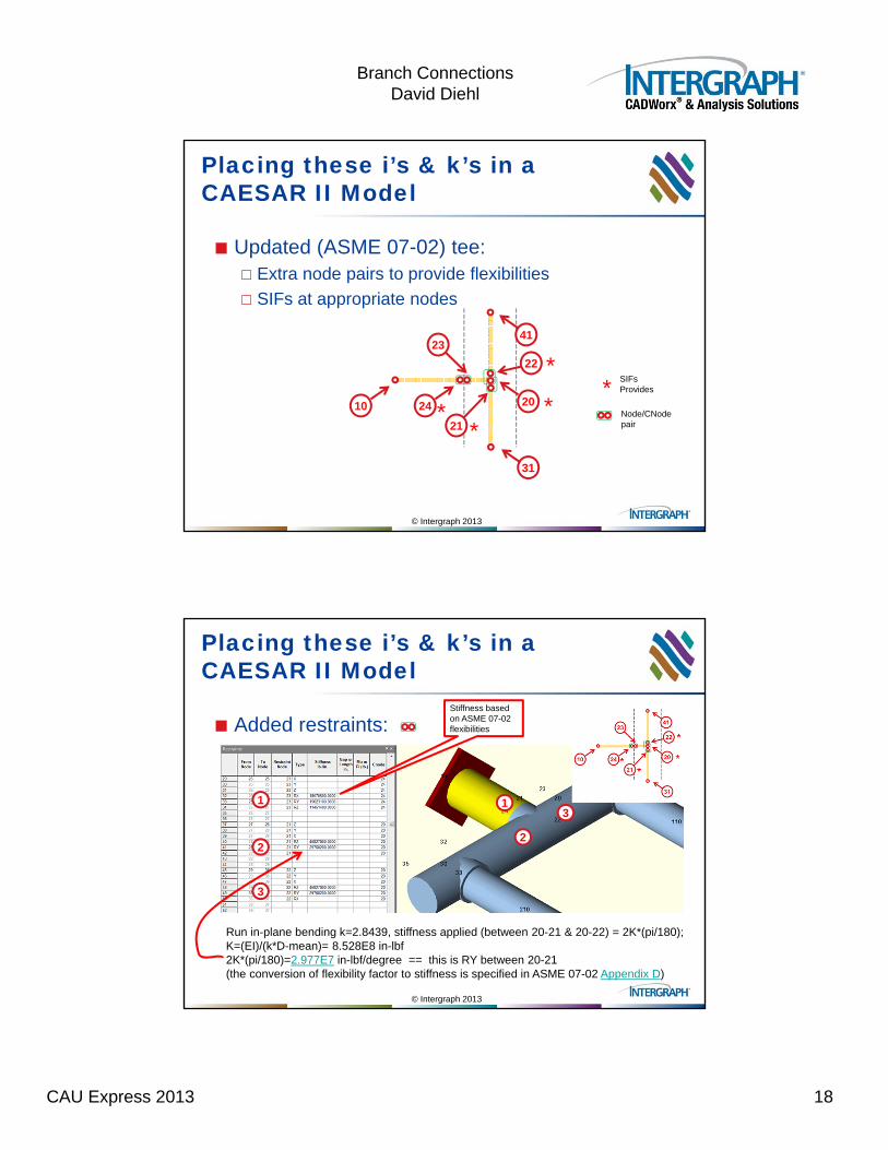
Placing these i’s & k’s in a CAESAR II Model
Updated (ASME 07-02) tee: Extra node pairs to provide flexibilities
SIFs at appropriate nodes
10
41
20
31
23
24
22
21*
**
*
*
SIFs Provides
Node/CNodepair
© Intergraph 2013
Placing these i’s & k’s in a CAESAR II Model
Added restraints:
1
2
31
2
3
Stiffness based on ASME 07-02 flexibilities
Run in-plane bending k=2.8439, stiffness applied (between 20-21 & 20-22) = 2K*(pi/180);K=(EI)/(k*D-mean)= 8.528E8 in-lbf2K*(pi/180)=2.977E7 in-lbf/degree == this is RY between 20-21(the conversion of flexibility factor to stiffness is specified in ASME 07-02 Appendix D)
CAU Express 2013 19
Branch ConnectionsDavid Diehl
© Intergraph 2013
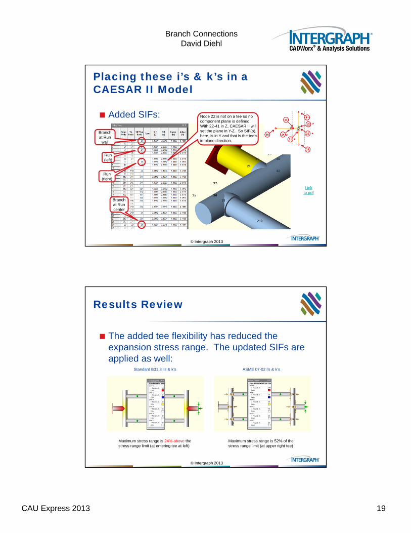
Placing these i’s & k’s in a CAESAR II Model
Added SIFs:
Branch at Run center
Branchat Run
wall
Run (left)
Run (right)
Link to pdf
Node 22 is not on a tee so no component plane is defined. With 22-41 in Z, CAESAR II will set the plane in Y-Z. So SIF(o), here, is in Y and that is the tee’s in-plane direction.
© Intergraph 2013
Results Review
The added tee flexibility has reduced the expansion stress range. The updated SIFs are applied as well:
Maximum stress range is 24% above the stress range limit (at entering tee at left)
Maximum stress range is 52% of the stress range limit (at upper right tee)
Standard B31.3 i’s & k’s ASME 07-02 i’s & k’s
CAU Express 2013 20
Branch ConnectionsDavid Diehl
© Intergraph 2013
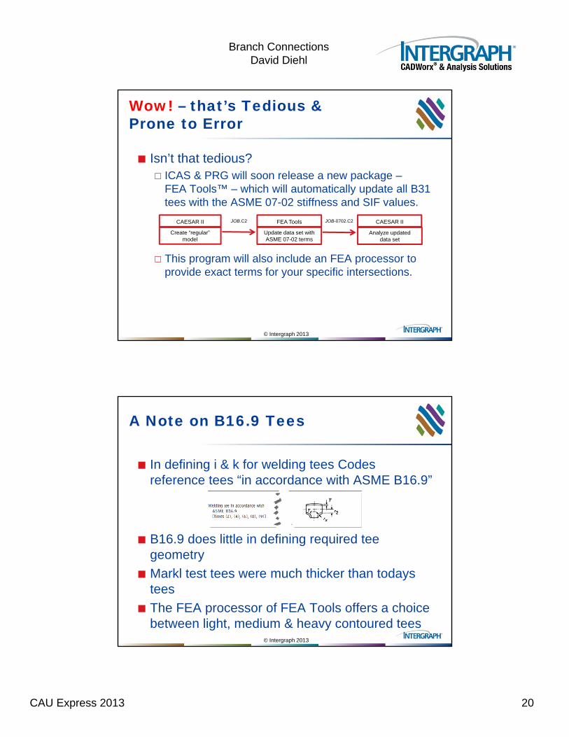
Wow! – that’s Tedious & Prone to Error
Isn’t that tedious? ICAS & PRG will soon release a new package –
FEA Tools™ – which will automatically update all B31 tees with the ASME 07-02 stiffness and SIF values.
This program will also include an FEA processor to provide exact terms for your specific intersections.
Create “regular” model
Update data set with ASME 07-02 terms
Analyze updateddata set
JOB-0702.C2JOB.C2 FEA ToolsCAESAR II CAESAR II
© Intergraph 2013
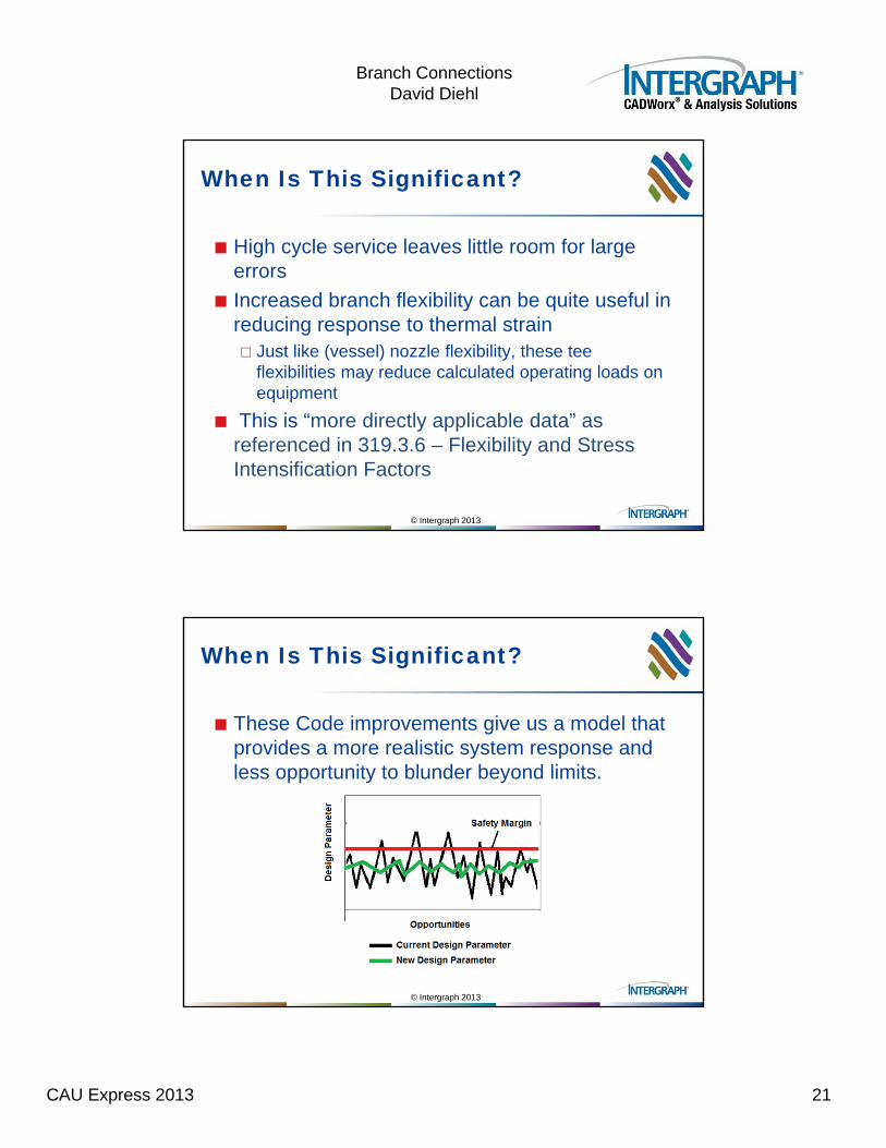
A Note on B16.9 Tees
In defining i & k for welding tees Codes reference tees “in accordance with ASME B16.9”
B16.9 does little in defining required tee geometry
Markl test tees were much thicker than todays tees
The FEA processor of FEA Tools offers a choice between light, medium & heavy contoured tees
CAU Express 2013 21
Branch ConnectionsDavid Diehl
© Intergraph 2013
When Is This Significant?
High cycle service leaves little room for large errors
Increased branch flexibility can be quite useful in reducing response to thermal strain Just like (vessel) nozzle flexibility, these tee
flexibilities may reduce calculated operating loads on equipment
This is “more directly applicable data” as referenced in 319.3.6 – Flexibility and Stress Intensification Factors
© Intergraph 2013
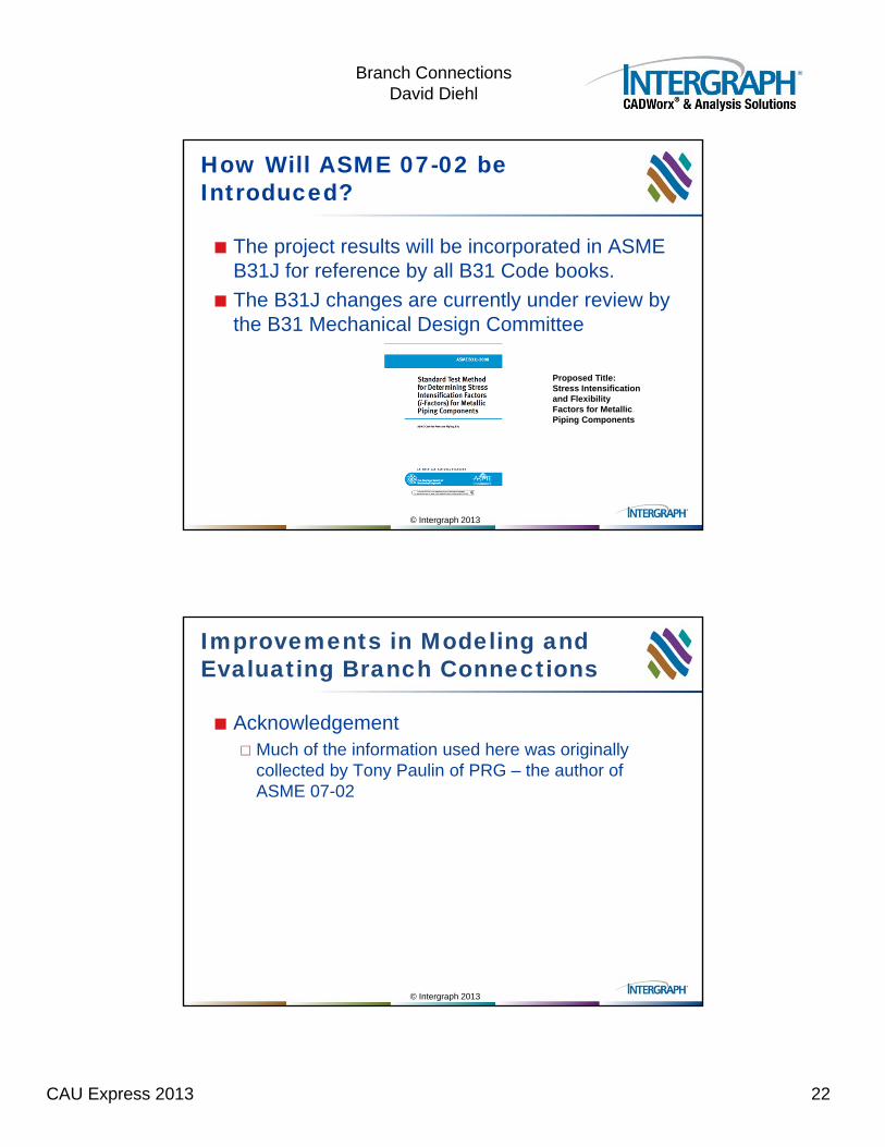
When Is This Significant?
These Code improvements give us a model that provides a more realistic system response and less opportunity to blunder beyond limits.
CAU Express 2013 22
Branch ConnectionsDavid Diehl
© Intergraph 2013
How Will ASME 07-02 be Introduced?
The project results will be incorporated in ASME B31J for reference by all B31 Code books.
The B31J changes are currently under review by the B31 Mechanical Design Committee
Proposed Title:Stress Intensification and Flexibility Factors for Metallic Piping Components
© Intergraph 2013
Improvements in Modeling and Evaluating Branch Connections
Acknowledgement Much of the information used here was originally
collected by Tony Paulin of PRG – the author of ASME 07-02
CAU Express 2013 23
Branch ConnectionsDavid Diehl
© Intergraph 2013
Improvements in Modeling and Evaluating Branch Connections
Questions? Comments?
© Intergraph 2013
Improvements in Modeling and Evaluating Branch Connections
CAU Express 2013 24
Branch ConnectionsDavid Diehl
© Intergraph 2013
Why only circle the “ior” values, why not “iob” also?
>>>this relates to the “obviously silly” comment Ev made in WRC 329 on p.22. You can see the huge difference in the i-factors. This was because Markl only tested size on size, and realizing that the run SIFs even for his tees were lower than the branch SIFs he decided to leave out special development for them. As a result, for small d/D intersection app D uses the size-on-size ii and io, when for io it’s “obviously silly”. It’s funny how many people don’t realize that they’re artificially penalizing their run pipes when they add small bore branch connections to their models. And WRC 329 states, “the piping analyst should use his judgment” (ref. below).
For the B31.3 (2008) table, why are the branch values different from the run values (branch equation used)?
>>>> This is the effective section modulus that confused SIF development even in the Code. (CAESAR has a correction for the B31.1 foul up made in the 90’s). This is all described in WRC 329. This would be a good bulletin to take on the flight. When d/D < 1 the branch uses the effective section modulus, which is essentially multiplying by t/T, making sure (i)(t/T) > 1. So the branch “real” i-factors are (i)(t/T). Ev recognized this could be a problem in 1961, but this was Markl’scorrection to in Code Case 51 to address the d/D<1 problem. 07-02 corrects this and puts lower bound limits on t/T. You can imagine, since for pressure d/t = D/T, when d/D gets small, t/T can get very small too. If D/T is still large, the high stress is in the run pipe…
The “note” below the slide states that the effective section modulus is no longer used, there is nothing in this slide that reflects that – right? One would have to go to the Code and see that Zeff has been removed?
>>> The 07-02 equations are based on M/Z x SIF, or PD/4T X SIF, or F/A x SIF, which is the nominal stress in the thing being analyzed times the SIF for that thing. We address that with the 07-02 modification in FEATools by removing the intersection description so that CAESAR uses the nominal stress in the straight pipe.