02 th!nk neighbor
118
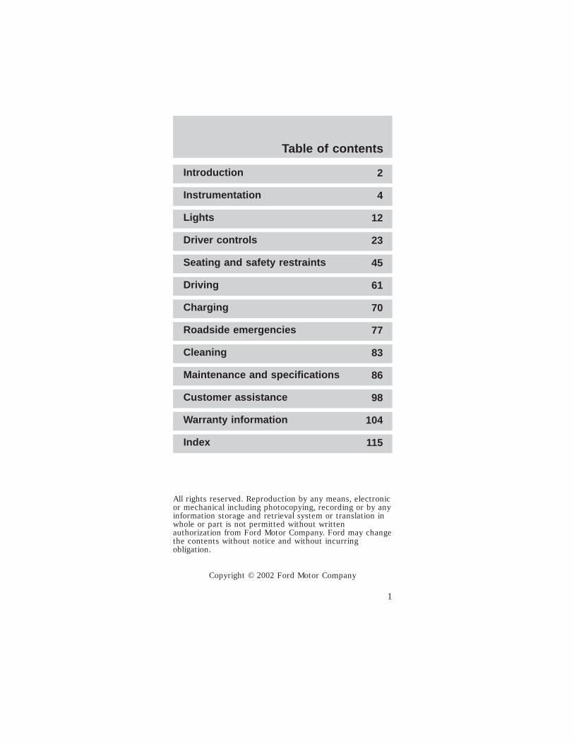
Introduction 2 Instrumentation 4 Lights 12 Driver controls 23 Seating and safety restraints 45 Driving 61 Charging 70 Roadside emergencies 77 Cleaning 83 Maintenance and specifications 86 Customer assistance 98 Warranty information 104 Index 115 All rights reserved. Reproduction by any means, electronic or mechanical including photocopying, recording or by any information storage and retrieval system or translation in whole or part is not permitted without written authorization from Ford Motor Company. Ford may change the contents without notice and without incurring obligation. Copyright © 2002 Ford Motor Company Table of contents 1
Transcript of 02 th!nk neighbor
Introduction 2
Instrumentation 4
Lights 12
Driver controls 23
Seating and safety restraints 45
Driving 61
Charging 70
Roadside emergencies 77
Cleaning 83
Maintenance and specifications 86
Customer assistance 98
Warranty information 104
Index 115
All rights reserved. Reproduction by any means, electronicor mechanical including photocopying, recording or by anyinformation storage and retrieval system or translation inwhole or part is not permitted without writtenauthorization from Ford Motor Company. Ford may changethe contents without notice and without incurringobligation.
Copyright © 2002 Ford Motor Company
Table of contents
1

The following warning may be required by Californialaw:
CALIFORNIA Proposition 65 Warning
Warning: This product contains or emitschemicals known to state of California to
cause cancer and birth defects or otherreproductive harm. In addition, certain fluids orcertain products of component wear contain oremit chemicals knot to the state of California tocause cancer and birth defects or otherreproductive harm.
ICONSIndicates a safety alert.Read the followingsection on warnings.
WARNINGS
Warnings provide information which may reduce therisk of personal injury to you and others.
BREAKING IN YOUR VEHICLE
There are no particular break-in schedules for thevehicle.
Proper charging and avoidance of over dischargingof the batteries will enhance their lives and capacity.Make sure to read Battery charging in the Drivingsection of this manual and Batteries in theMaintenance and specifications section of thismanual.
These are some of the symbols you may see on yourvehicle.
Safety Alert
Introduction
2
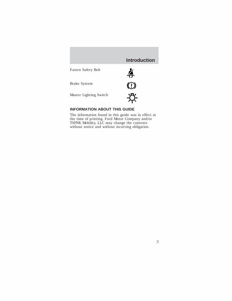
Fasten Safety Belt
Brake System
Master Lighting Switch
INFORMATION ABOUT THIS GUIDEThe information found in this guide was in effect atthe time of printing. Ford Motor Company and/orTH!NK Mobility, LLC may change the contentswithout notice and without incurring obligation.
Introduction
3

GAUGES
The instrument cluster LCD (liquid crystal display),referred to as the “gauge,” will be activated if any ofthe following conditions exist:• Key switch is on• Vehicle batteries are being recharged
1. Safety belt warningindicator
The safety beltwarning icon willilluminate for 30seconds after thevehicle is switched into D (Drive) mode.
2. Speedometer gaugeLCD
A two-digit LCD gaugedisplay shows thevehicle speed in eitherMPH or KPH,depending on the selected mode. Vehicle speed isshown while in R (Reverse), T (Turf), and D(Drive) modes. The top speed of your vehicle inDrive mode is 25 mph (40 km/h) and 15 mph (24km/h) in Turf mode.
1 213
3
12
11
10 9 8 7
6
5
4
Instrumentation
4

3. Right turn signalindicator
The arrow will flashwhen the turn signal lever is pushed up. If theindicator flashes at a fast rate, it has amalfunction, such as a burned out bulb.
4. Odometer/trip counterdisplay
A five-digit LCDdisplay shows thetotal accumulated miles traveled. The display maybe changed to measure a particular trip distance.The drive mode selector switch must be in the T(Turf) or D (Drive) mode for this function. Whenthe vehicle is restarted, the display will return tothe last mode manually set.
Changing and resetting the modes
The odometer/trip modes can be changed bypressing the Select/Reset button on theinstrument cluster. The word “TRIP” will bedisplayed next to the five-digit display when inTrip mode. To measure a specific trip mileage,with the drive mode selector switch in T (Turf) orD (Drive) reset the trip odometer by pushing andholding the Select/Reset button down for threeseconds.
5. Drive systemover-temperatureindicator
This icon willilluminate if the drive system overheats. Thevehicle will drive normally 30 seconds, after whichpower will be limited and will remain limited untilthe drive system cools.
Instrumentation
5

6. Service requiredindicator
The icon willilluminate when thevehicle has a malfunction in the motor controller.Cycle the service disconnect switch off and thenback on. The service disconnect switch is locatedbelow and behind the parking brake lever withinthe seat stanchion (battery cover). It is a blackrubber switch and faces the front of the vehicle.To access the service disconnect switch, removethe seat stanchion front cover, refer to Floodedtype batteries in Maintenance andspecifications. If the service required indicator isstill on, take your vehicle to an authorized Dealerfor the required maintenance to maintain your fullwarranty coverge.
7. Battery waterreminder indicator
This icon indicatesthat your vehicle’sbatteries require amaintenance check of the battery fluid levels.Distilled water or demineralized water mustbe added as needed. Your vehicle comesequipped with one of two types of batteries:“flooded”, requiring water level checks andmaintenance refills; or the optional sealedmaintenance free, for which no maintenance isrequired. This indicator will be disabled if yourvehicle is equipped with sealed batteries. If youchange the type of battery in your vehicle, theTH!NK dealer will need to change the batterysetting in the gauge.
Resetting the battery water reminder indicator
Once the battery water has been checked, resetthe reminder by pressing and holding theSelect/Reset button for over three seconds whilein the R (Reverse) mode. The reminder will onlybe reset during the following conditions: R(Reverse) mode is selected with the drive mode
Instrumentation
6
selector switch; instrument cluster gauge is inflooded battery mode.
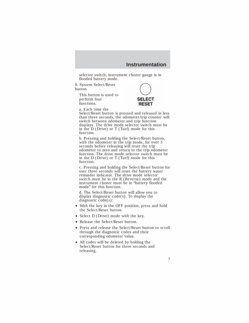
8. System Select/Resetbutton
This button is used toperform fourfunctions.
a. Each time theSelect/Reset button is pressed and released in lessthan three seconds, the odometer/trip counter willswitch between odometer and trip functiondisplays. The drive mode selector switch must bein the D (Drive) or T (Turf) mode for thisfunction.b. Pressing and holding the Select/Reset button,with the odometer in the trip mode, for over 3seconds before releasing will reset the tripodometer to zero and return to the trip odometerfunction. The drive mode selector switch must bein the D (Drive) or T (Turf) mode for thisfunction.c. Pressing and holding the Select/Reset button forover three seconds will reset the battery waterreminder indicator. The drive mode selectorswitch must be in the R (Reverse) mode and theinstrument cluster must be in “battery floodedmode” for this function.d. The Select/Reset button will allow you todisplay diagnostic code(s). To display thediagnostic code(s):
• With the key in the OFF position, press and holdthe Select/Reset button.
• Select D (Drive) mode with the key.
• Release the Select/Reset button.
• Press and release the Select/Reset button to scrollthrough the diagnostic codes and theircorresponding odometer value.
• All codes will be deleted by holding theSelect/Reset button for three seconds andreleasing.
Instrumentation
7
• Exit Service mode by selecting the OFF modewith the key.
• Press and release the Select/Reset button.
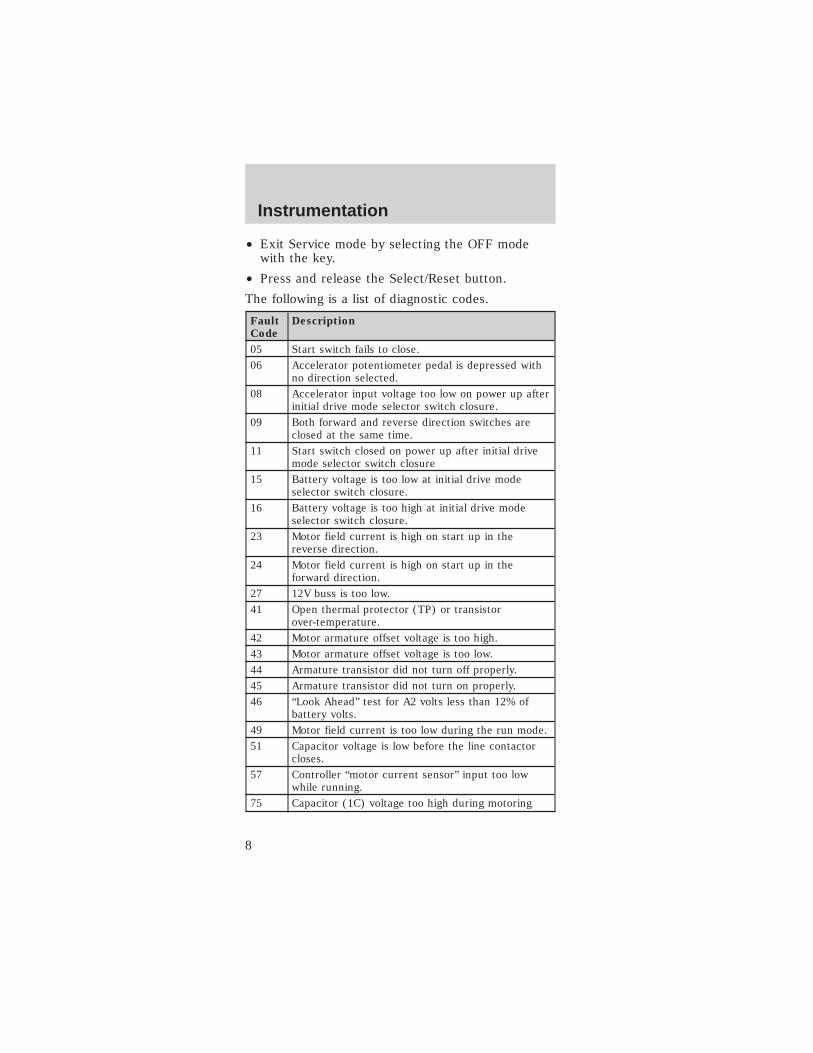
The following is a list of diagnostic codes.
Fault
Code
Description
05 Start switch fails to close.
06 Accelerator potentiometer pedal is depressed withno direction selected.
08 Accelerator input voltage too low on power up afterinitial drive mode selector switch closure.
09 Both forward and reverse direction switches areclosed at the same time.
11 Start switch closed on power up after initial drivemode selector switch closure
15 Battery voltage is too low at initial drive modeselector switch closure.
16 Battery voltage is too high at initial drive modeselector switch closure.
23 Motor field current is high on start up in thereverse direction.
24 Motor field current is high on start up in theforward direction.
27 12V buss is too low.
41 Open thermal protector (TP) or transistorover-temperature.
42 Motor armature offset voltage is too high.
43 Motor armature offset voltage is too low.
44 Armature transistor did not turn off properly.
45 Armature transistor did not turn on properly.
46 “Look Ahead” test for A2 volts less than 12% ofbattery volts.
49 Motor field current is too low during the run mode.
51 Capacitor voltage is low before the line contactorcloses.
57 Controller “motor current sensor” input too lowwhile running.
75 Capacitor (1C) voltage too high during motoring
Instrumentation
8
Fault
Code
Description
76 Capacitor (1C) voltage too high during regenerativebraking.
90 Motor thermostat is open during control operation.
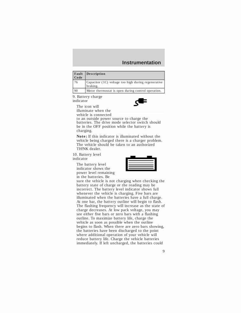
9. Battery chargeindicator
The icon willilluminate when thevehicle is connectedto an outside power source to charge thebatteries. The drive mode selector switch shouldbe in the OFF position while the battery ischarging.
Note: If this indicator is illuminated without thevehicle being charged there is a charger problem.The vehicle should be taken to an authorizedTH!NK dealer.
10. Battery levelindicator
The battery levelindicator shows thepower level remainingin the batteries. Besure the vehicle is not charging when checking thebattery state of charge or the reading may beincorrect. The battery level indicator shows fullwhenever the vehicle is charging. Five bars areilluminated when the batteries have a full charge.At one bar, the battery outline will begin to flash.The flashing frequency will increase as the state ofcharge decreases. At low pack voltage, you maysee either five bars or zero bars with a flashingoutline. To maximize battery life, charge thevehicle as soon as possible when the outlinebegins to flash. When there are zero bars showing,the batteries have been discharged to the pointwhere additional operation of your vehicle willreduce battery life. Charge the vehicle batteriesimmediately. If left uncharged, the batteries could
Instrumentation
9
discharge to the point where the battery chargerwill not turn on and battery damage may occur.
After a partial charge, the level may read higherthan it actually is. Driving a few miles will causethe battery gauge to settle to an accurate level.
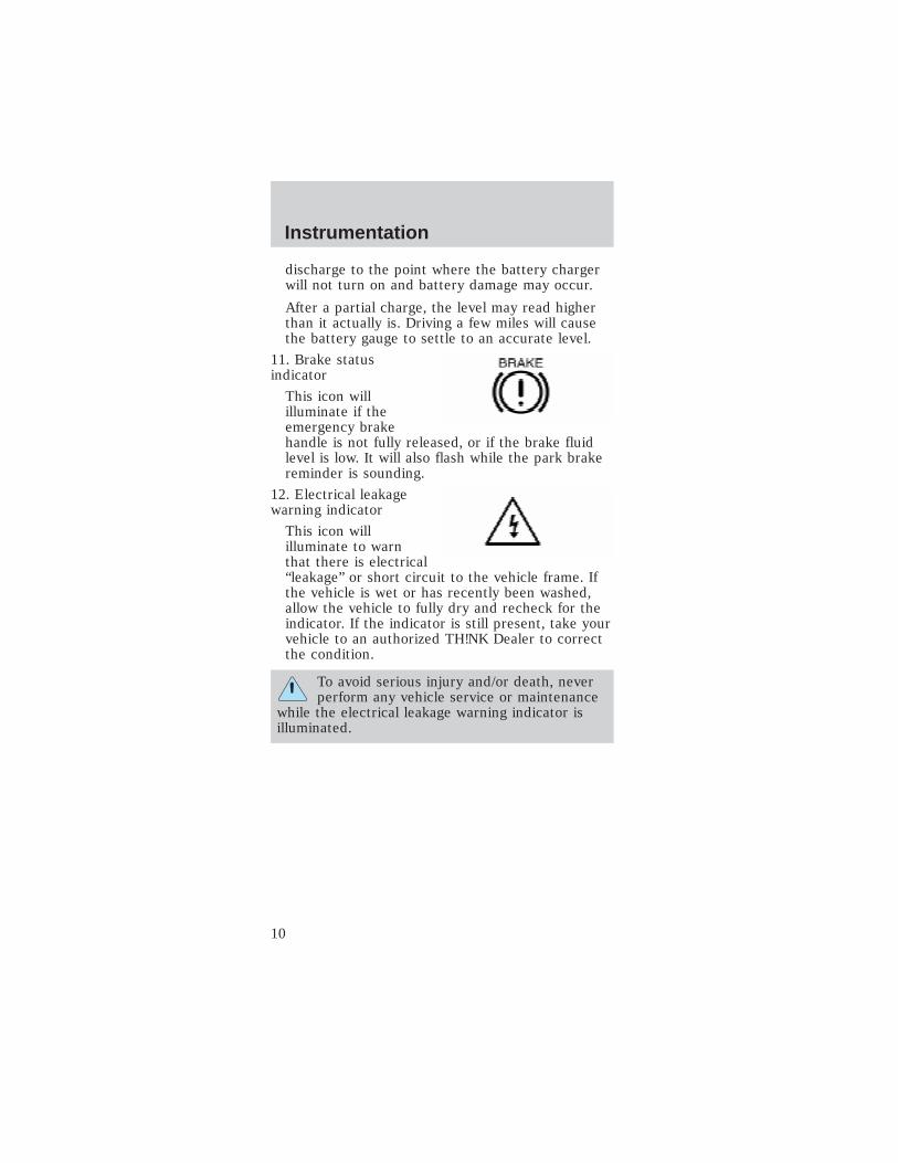
11. Brake statusindicator
This icon willilluminate if theemergency brakehandle is not fully released, or if the brake fluidlevel is low. It will also flash while the park brakereminder is sounding.
12. Electrical leakagewarning indicator
This icon willilluminate to warnthat there is electrical“leakage” or short circuit to the vehicle frame. Ifthe vehicle is wet or has recently been washed,allow the vehicle to fully dry and recheck for theindicator. If the indicator is still present, take yourvehicle to an authorized TH!NK Dealer to correctthe condition.
To avoid serious injury and/or death, neverperform any vehicle service or maintenance
while the electrical leakage warning indicator isilluminated.
Instrumentation
10

This vehicle contains a high voltageelectrical system. Serious injury, death,
and/or property damage may result if this vehicleis not properly used, charged or serviced as statedin this manual. Read this owner’s guide prior touse, charging, or servicing this vehicle. Do notdrill, cut, or modify any part of this vehicle, ashigh voltage wiring is present. Do not use jumpercables. Only charge this vehicle with an approvedGFCI cord as stated in Battery charging.
13. Left turn signalindicator
The arrow will flashwhen the turn signal lever is pushed down. If theindicator flashes at a fast rate, it has amalfunction, such as a burned out bulb.
Audible IndicatorsPark brake reminder
The park brake reminder has a tone that sounds for10 seconds when the drive mode selector switch isturned to the OFF position with the parking brakenot set. It stops after 10 seconds or when theparking brake is engaged. During this time thevehicle is “active” with functional park brakereminder and the gauge will be active and backlit.After 10 seconds, the vehicle shuts down and parkbrake reminder is no longer functional.
To avoid serious injury, death, and/orproperty damage, always engage the parking
brake before leaving the vehicle.
Reverse alarm
When the vehicle is in R (Reverse), a tone isgenerated to alert the driver and pedestrians.
Instrumentation
11
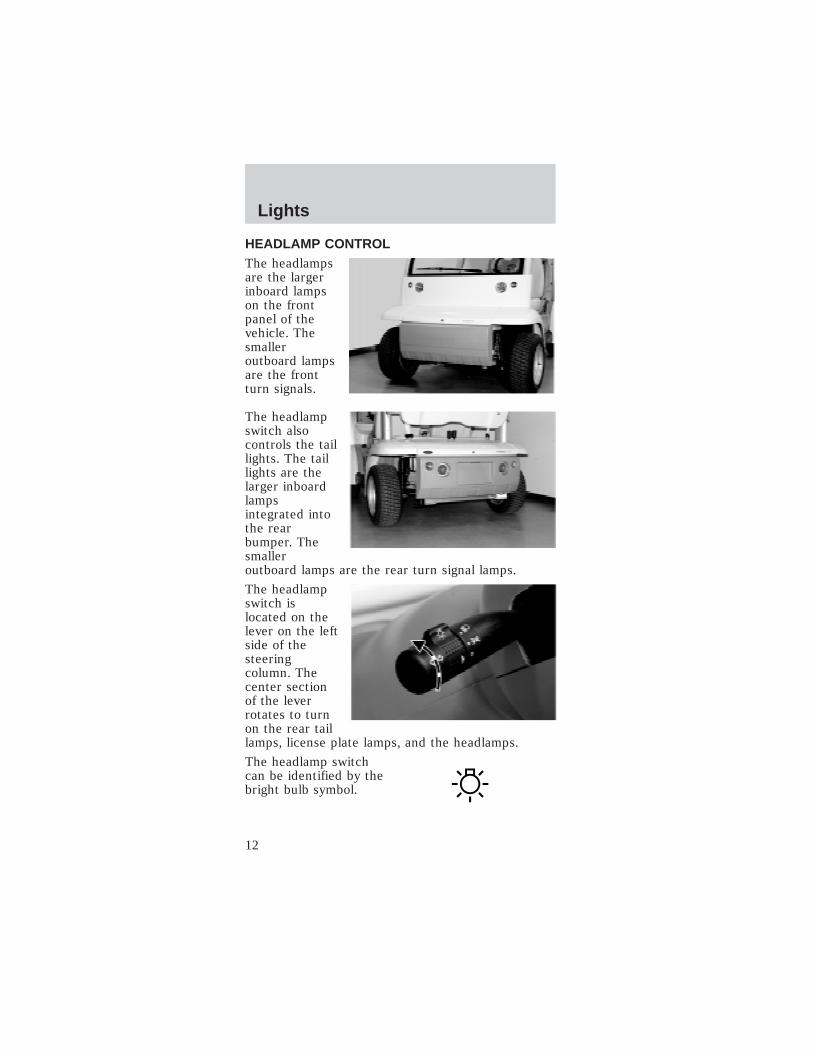
HEADLAMP CONTROLThe headlampsare the largerinboard lampson the frontpanel of thevehicle. Thesmalleroutboard lampsare the frontturn signals.
The headlampswitch alsocontrols the taillights. The taillights are thelarger inboardlampsintegrated intothe rearbumper. Thesmalleroutboard lamps are the rear turn signal lamps.
The headlampswitch islocated on thelever on the leftside of thesteeringcolumn. Thecenter sectionof the leverrotates to turnon the rear taillamps, license plate lamps, and the headlamps.
The headlamp switchcan be identified by thebright bulb symbol.
Lights
12

Always remember to turn on yourheadlamps at dusk and dawn and during
inclement weather. Failure to activate yourheadlamps under these conditions could result in acollision.
The OFF position isindicated on the lever bythe O. When the switcharrowhead is alignedwith the O symbol, the exterior lamps are off. Thelights will not operate in the key OFF mode.
The first position abovethe OFF position is therear tail lamps andlicense plate lamp.
The second positionabove the OFF positionwill illuminate theheadlamps while therear tail lamps and license plate lamps remain on.
Pulling the headlamp switch rearward while it is inthe OFF position will cause the headlamps to turnon as long as the switch is held rearward. There areno high beams on this vehicle. Pulling the headlampswitch rearward while it is in the ON position willNOT change the performance of the headlamps.
Lights
13

TURN SIGNAL CONTROLThe headlampswitch leveralso controlsthe turn signals.Push down toactivate the leftturn signal, andpush up toactivate theright turnsignal. Thearrow indicator will flash on the instrument clusterindicating that the turn signal is on.
AIMING THE HEADLAMPS
The headlamps on your vehicle are properly aimedat the assembly plant.
If your vehicle has been in an accident the alignmentof your headlamps should be checked by a qualifiedservice technician.
Vertical aim adjustment
1. Park the vehicle on a level surface approximately7.6 meters (25 feet) from a vertical wall or screendirectly in front of it.
• (A) 2.43 meters (8 feet)
• (B) Height of top of lamp beam to ground
• (C) 6.09 meters (25 feet)
• (D) Horizontal reference line
Lights
14

2. Turn on the headlamps to illuminate the wall orscreen.
3. On the wall or screen you will observe an area ofhigh intensity light. The top of the high intensityarea should be between 0.61 meters (2 ft) and 0.69meters (2 ft 3 in) above the ground. If not, the beamwill need to be adjusted by a qualified TH!NKtechnician.
BULB REPLACEMENT
Headlamps
To remove the headlamp bulb:
1. Remove thescrivet and thecowl tray panel.
A
D
B
C
Lights
15
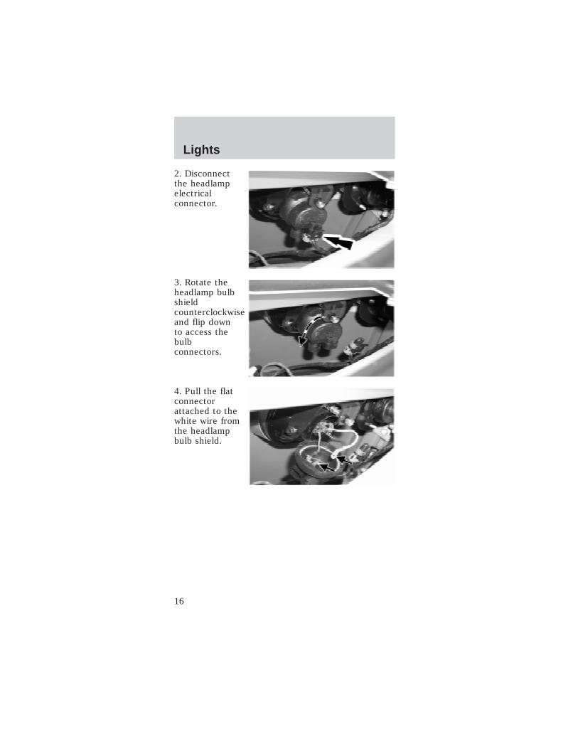
2. Disconnectthe headlampelectricalconnector.
3. Rotate theheadlamp bulbshieldcounterclockwiseand flip downto access thebulbconnectors.
4. Pull the flatconnectorattached to thewhite wire fromthe headlampbulb shield.
Lights
16

5. Push andsqueeze the twobulb retainerwires todisengage themfrom theheadlamphousing.Remove theheadlamp bulb.
To install the headlamp bulb:
Handle the halogen headlamp bulb carefullyand keep out of the children’s reach. Grasp
the bulb only by its metal base and do not touchthe glass. The oil from your hand could cause thebulb to break the next time the headlamps areoperated.
1. Install theheadlamp bulb.Squeeze andpush the twobulb retainerwires to engagethem to theheadlamphousing.
2. Push the flatconnectorattached to thewhite wire intothe headlampbulb shield.
Lights
17
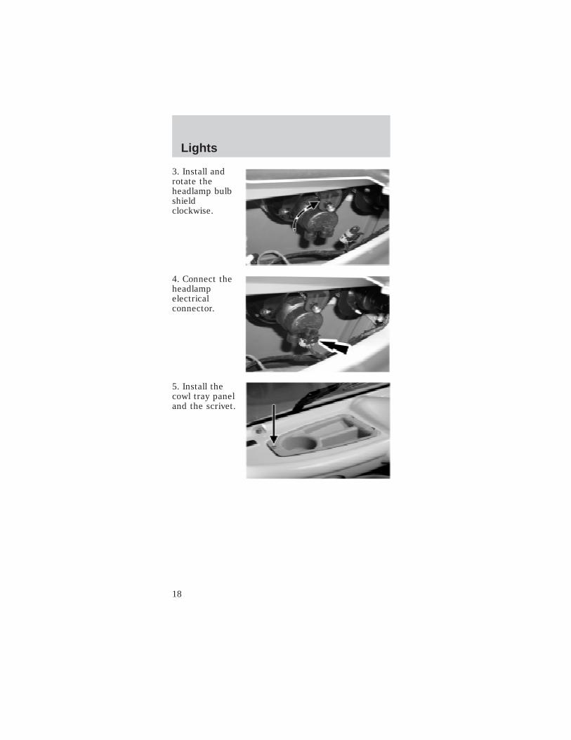
3. Install androtate theheadlamp bulbshieldclockwise.
4. Connect theheadlampelectricalconnector.
5. Install thecowl tray paneland the scrivet.
Lights
18

Replacing the front turn signals1. Remove thescrivet and cowltray panel.(Driver sideshown; thepassenger sideis similar.)
2. Twist counterclockwise and remove the front turnsignal bulb retainer.
3. Remove thebulb.
4. Install thenew bulb.
5. Install theremovedcomponents.
Replacing the rear high-mount stop and reverselamp bulbs1. Remove thetwo screws andpull out thelamp assemblyto expose thebulb sockets onthe back.
Lights
19

2. Rotate thebulb socketcounterclockwiseand pull out toaccess the bulb.
3. To remove the bulb, pull it straight out of thesocket.4. Insert a new bulb into the socket until it is fullyseated.5. Install the socket into the back of the lampassembly and turn clockwise until it is locked intoplace.6. Position the lamp assembly into the vehiclehousing and install the two screws. Tighten thescrews firmly, but do not over-tighten.Over-tightening can cause damage to the lamp.
Replacing the rear turn signals1. Unlock andremove thedecklid (ifequipped).
2. From insidethe rear wheelhousings,remove the sixrear bumperbolts andcarefully lowerthe bumper.
3. Twist counterclockwise and remove the rear turnsignal bulb retainer.
Lights
20
4. Remove the bulb.
5. Install the new bulb.
6. Install the removed parts. Tighten the rearbumper bolts to 8–10 N•m.
7. Install and lock the decklid.
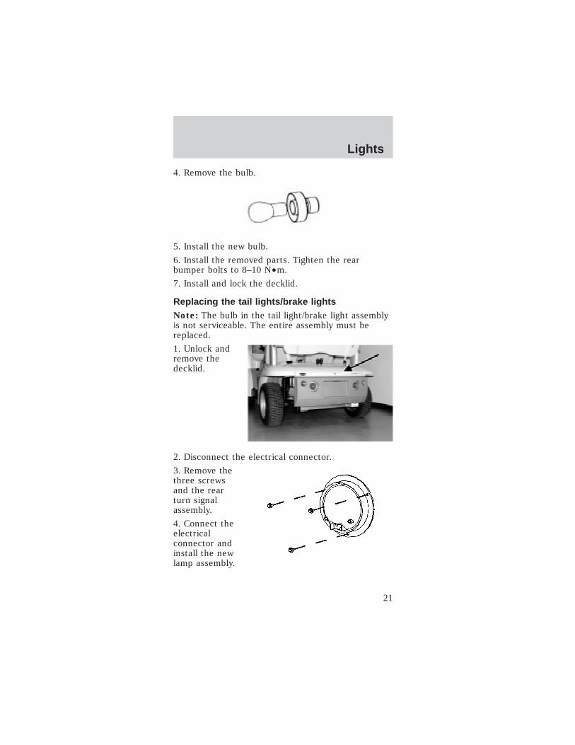
Replacing the tail lights/brake lightsNote: The bulb in the tail light/brake light assemblyis not serviceable. The entire assembly must bereplaced.
1. Unlock andremove thedecklid.
2. Disconnect the electrical connector.
3. Remove thethree screwsand the rearturn signalassembly.
4. Connect theelectricalconnector andinstall the newlamp assembly.
Lights
21
5. Tighten the screws firmly, but do not over-tighten.
6. Install and lock the decklid.
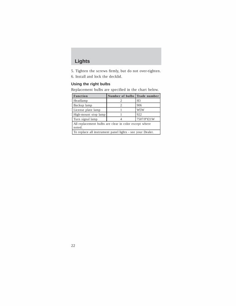
Using the right bulbsReplacement bulbs are specified in the chart below.
Function Number of bulbs Trade number
Headlamp 2 H3
Backup lamp 2 906
License plate lamp 1 W5W
High-mount stop lamp 1 922
Turn signal lamp 4 7507/PY21W
All replacement bulbs are clear in color except wherenoted.
To replace all instrument panel lights - see your Dealer.
Lights
22
WINDSHIELD WIPER/WASHER
Front wiper control
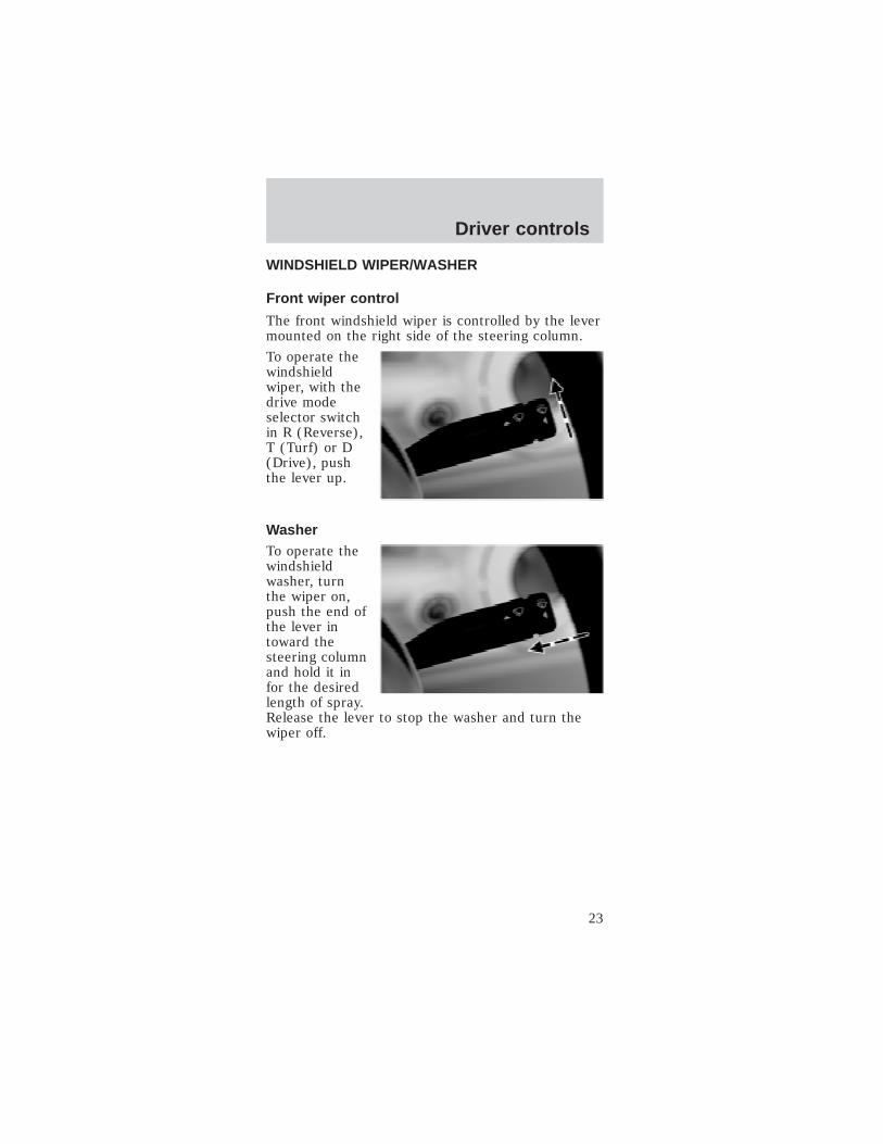
The front windshield wiper is controlled by the levermounted on the right side of the steering column.
To operate thewindshieldwiper, with thedrive modeselector switchin R (Reverse),T (Turf) or D(Drive), pushthe lever up.
WasherTo operate thewindshieldwasher, turnthe wiper on,push the end ofthe lever intoward thesteering columnand hold it infor the desiredlength of spray.Release the lever to stop the washer and turn thewiper off.
Driver controls
23
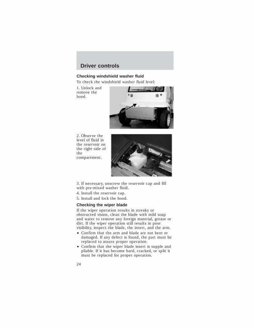
Checking windshield washer fluidTo check the windshield washer fluid level:
1. Unlock andremove thehood.
2. Observe thelevel of fluid inthe reservoir onthe right side ofthecompartment.
3. If necessary, unscrew the reservoir cap and fillwith pre-mixed washer fluid.4. Install the reservoir cap.5. Install and lock the hood.
Checking the wiper bladeIf the wiper operation results in streaky orobstructed vision, clean the blade with mild soapand water to remove any foreign material, grease ordirt. If the wiper operation still results in poorvisibility, inspect the blade, the insert, and the arm.• Confirm that the arm and blade are not bent or
damaged. If any defect is found, the part must bereplaced to assure proper operation.
• Confirm that the wiper blade insert is supple andpliable. If it has become hard, cracked, or split itmust be replaced for proper operation.
Driver controls
24
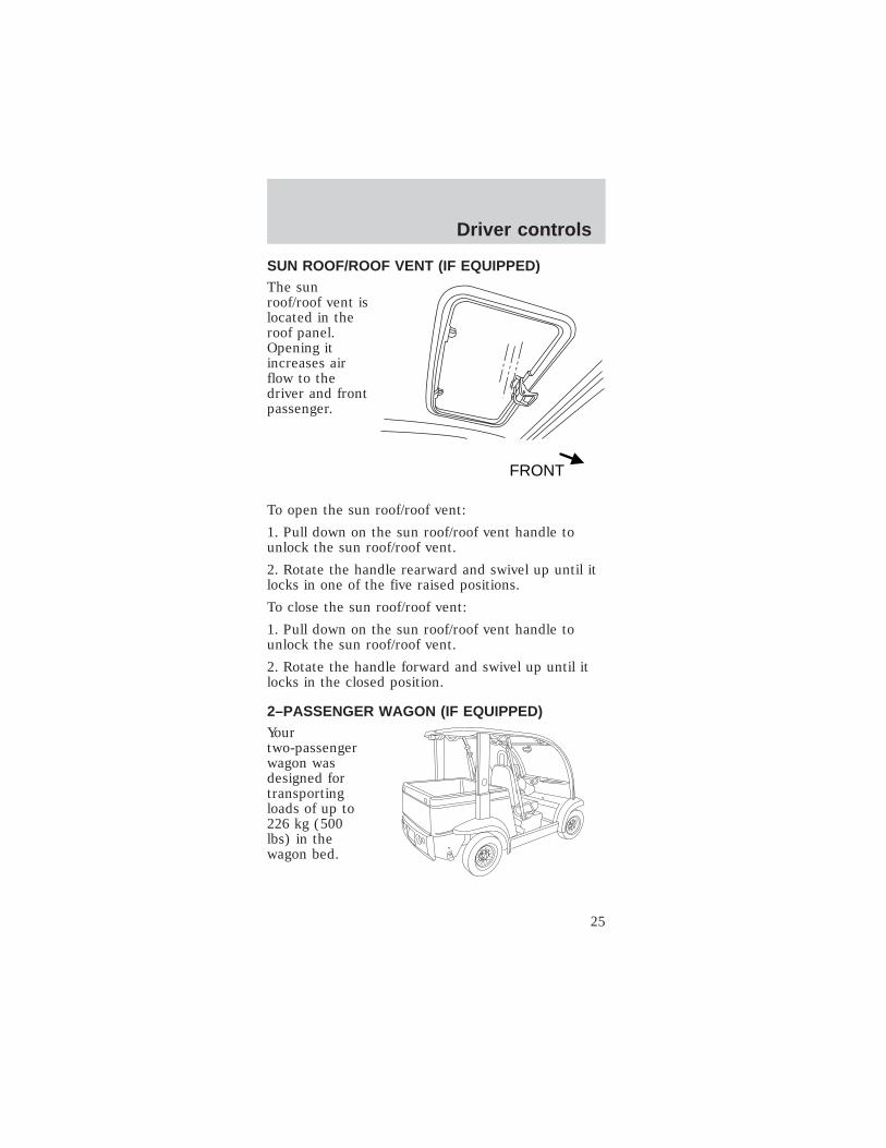
SUN ROOF/ROOF VENT (IF EQUIPPED)The sunroof/roof vent islocated in theroof panel.Opening itincreases airflow to thedriver and frontpassenger.
To open the sun roof/roof vent:
1. Pull down on the sun roof/roof vent handle tounlock the sun roof/roof vent.
2. Rotate the handle rearward and swivel up until itlocks in one of the five raised positions.
To close the sun roof/roof vent:
1. Pull down on the sun roof/roof vent handle tounlock the sun roof/roof vent.
2. Rotate the handle forward and swivel up until itlocks in the closed position.
2–PASSENGER WAGON (IF EQUIPPED)Yourtwo-passengerwagon wasdesigned fortransportingloads of up to226 kg (500lbs) in thewagon bed.
FRONT
Driver controls
25

Wagon bedThe wagon bedwas designedfor easy loadingand unloading.Pressing thetwo latchesinward towardthe middle ofthe tailgate andpulling toward you will open the tailgate.
HEATER/DEFOGGER (IF EQUIPPED)
The heater/defogger system is a single speed fixedtemperature system. There are no controls to adjustfan speed or outlet air temperature.
Air distribution
The air flow volume and direction can be regulatedwith the side registers.
Side registers
Adjust as necessary for comfort or to direct air tothe windows for defogging.
Heater/defogger switch
Operating the heater/defogger switch will energizethe heater/defogger system for approximately 5–10minutes. After which it will automatically shut off. Ifrequired, the system can be reenergized byoperating the switch again. Pressing theheater/defogger switch while the system is operatingwill turn the system off.
Note: Operating the heater/defogger system useshigh amounts of energy and greatly reduces thevehicle range. Only operate the heater/defoggersystem when necessary.
Driver controls
26

HORNTo activate thehorn, push oneof the threehorn contactpoints on thesteering wheel.
CUPHOLDER
Your vehicle is equipped with a number ofconvenient cupholders, depending on which storagetrays your vehicle has.
Driver sideinstrumentpanel storagetray withcupholder andstoragecompartments(Passenger sideis similar.)
Optional cowltray with sportpackage.
Driver controls
27
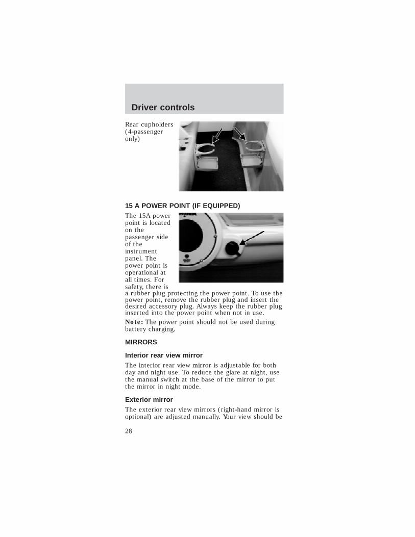
Rear cupholders(4-passengeronly)
15 A POWER POINT (IF EQUIPPED)The 15A powerpoint is locatedon thepassenger sideof theinstrumentpanel. Thepower point isoperational atall times. Forsafety, there isa rubber plug protecting the power point. To use thepower point, remove the rubber plug and insert thedesired accessory plug. Always keep the rubber pluginserted into the power point when not in use.Note: The power point should not be used duringbattery charging.
MIRRORS
Interior rear view mirrorThe interior rear view mirror is adjustable for bothday and night use. To reduce the glare at night, usethe manual switch at the base of the mirror to putthe mirror in night mode.
Exterior mirrorThe exterior rear view mirrors (right-hand mirror isoptional) are adjusted manually. Your view should be
Driver controls
28

adjusted so that the vehicle’s rear tires are justvisible in the bottom inside corner of the mirror.This will minimize any “blind spot” in your field ofview.
Always confirm it is clear behind you beforechanging lanes or backing up to avoid a
collision.
GOLF RACK (IF EQUIPPED)To mount golfbags in the golfrack:
1. Unlock the decklid. To remove the decklid, liftand raise the decklid.
2. Pull rearwardon the bag beltwebbingrelease/lockinglever.
3. Pull the webbing out of the release/locking lever.
Note: The base of the golf bag should rest on thetop of the golf bag tray.
Driver controls
29
4. Position the golf bag in the trunk area.
5. Route the webbing through the golf bag handleand through the release/locking lever.
6. Remove any slack from the webbing and lock therelease/locking lever.
FLOOR MATS
The floor mats are fastened to the floor with scrivetsthat can be loosened and removed for cleaningunder the floor mats.
SCORECARD HOLDER (IF EQUIPPED)
The scorecard holder is attached to the glove boxdoor with magnets after attaching a magnetic disc tothe glove box door.
STEREO (IF EQUIPPED)
For operating instructions for the stereo, pleaserefer to the instructions provided with the unit.
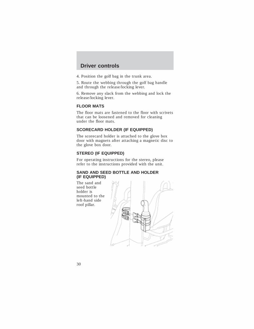
SAND AND SEED BOTTLE AND HOLDER(IF EQUIPPED)The sand andseed bottleholder ismounted to theleft-hand sideroof pillar.
Driver controls
30

BALL AND CLUB WASHER (IF EQUIPPED)
The ball and club washer is mounted to theleft-hand side roof pillar.
To drain and fill the ball and club washer:
1. Remove thefront and rearrubber plugs.Let the oldwater drain.
2. Remove the five screws from the bottom of thecover. Remove the cover.
Driver controls
31
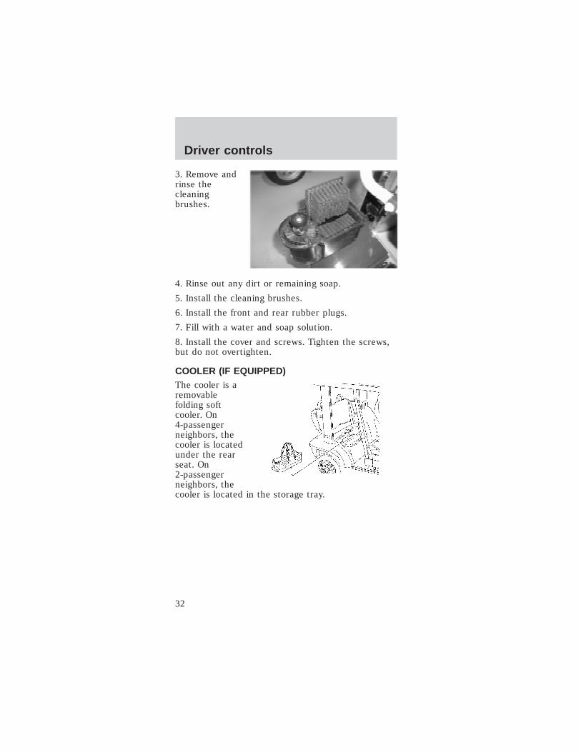
3. Remove andrinse thecleaningbrushes.
4. Rinse out any dirt or remaining soap.
5. Install the cleaning brushes.
6. Install the front and rear rubber plugs.
7. Fill with a water and soap solution.
8. Install the cover and screws. Tighten the screws,but do not overtighten.
COOLER (IF EQUIPPED)The cooler is aremovablefolding softcooler. On4-passengerneighbors, thecooler is locatedunder the rearseat. On2-passengerneighbors, thecooler is located in the storage tray.
Driver controls
32

WEATER BASKET (IF EQUIPPED)The sweaterbasket ismounted to abracketbetween therear roofB-pillars.
Note: The sweater basket should not be used tocarry heavy objects.
SWEATER NET (IF EQUIPPED)The sweater netdrapes over thefront seat and isheld in place bya locking claspthat routesaround thelower part ofthe seat frame.
Place only soft, light-weight objects in thenet. Hard, heavy objects in the net could
cause injury in a collision.
Driver controls
33
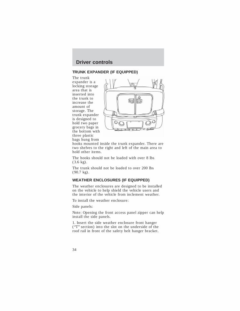
TRUNK EXPANDER (IF EQUIPPED)The trunkexpander is alocking storagearea that isinserted intothe trunk toincrease theamount ofstorage. Thetrunk expanderis designed tohold two papergrocery bags inthe bottom withthree plasticbags hung fromhooks mounted inside the trunk expander. There aretwo shelves to the right and left of the main area tohold other items.
The hooks should not be loaded with over 8 lbs(3.6 kg).
The trunk should not be loaded to over 200 lbs(90.7 kg).
WEATHER ENCLOSURES (IF EQUIPPED)
The weather enclosures are designed to be installedon the vehicle to help shield the vehicle users andthe interior of the vehicle from inclement weather.
To install the weather enclosure:
Side panels:
Note: Opening the front access panel zipper can helpinstall the side panels.
1. Insert the side weather enclosure front hanger(“T” section) into the slot on the underside of theroof rail in front of the safety belt hanger bracket.
Driver controls
34
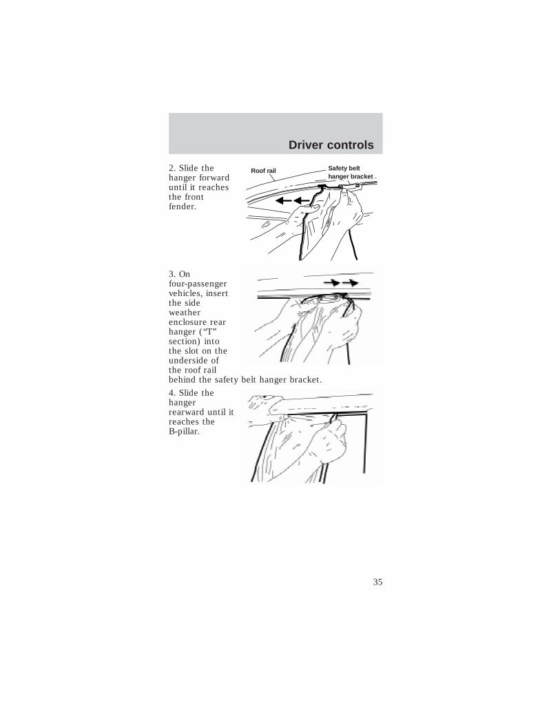
2. Slide thehanger forwarduntil it reachesthe frontfender.
3. Onfour-passengervehicles, insertthe sideweatherenclosure rearhanger (“T”section) intothe slot on theunderside ofthe roof railbehind the safety belt hanger bracket.
4. Slide thehangerrearward until itreaches theB-pillar.
Safety belthanger bracket
Roof rail
Driver controls
35

5. Wrap andfasten the largeupper attachingstrap aroundthe B-pillar.
6. Wrap andfasten the two1-inch attachingstraps. Insertthe attachingstraps throughthe D-ring andfasten securely.
7. Attach thethree mountinghooks to theopenings in theframe rail.
8. Repeat steps 1- 7 for the opposite side of thevehicle.
Rear panels:
Front ofvehicle
Front ofvehicle
Driver controls
36

9. Insert therear weatherenclosurehanger into theslot near thehigh-mount stoplamp.
10. Slide thehanger towardthe B-pillar.
11. Zip the tworear weatherenclosure toside weatherenclosurezippers.
Driver controls
37

12. On2–passengerand4–passengervehicles, attachthe two rearmounting hooksto the rearfenders.
13. On2–passengerwagons, attach the rear mounting hooks to theunderside of the rear bumper.
To remove the vehicle’s weather enclosure:
1. On2–passengerwagons,unfasten therear mountinghooks from theunderside ofthe rearbumper.
2. On2–passengerand 4–passenger vehicles, unfasten the two rearmounting hooks to the rear fenders.
3. Unzip thetwo rearweatherenclosure toside weatherenclosurezippers
Driver controls
38
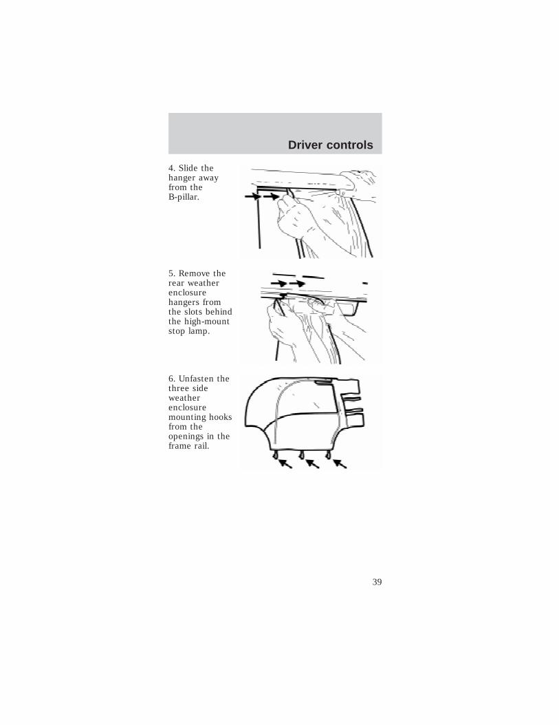
4. Slide thehanger awayfrom theB-pillar.
5. Remove therear weatherenclosurehangers fromthe slots behindthe high-mountstop lamp.
6. Unfasten thethree sideweatherenclosuremounting hooksfrom theopenings in theframe rail.
Driver controls
39

7. Pull apart thelarge upper andlower attachingstraps.
8. Pull apart thetwo 1-inchattachingstraps.
9. Slide thehanger forwardaway from theB-pillar.
Front ofvehicle
Front ofvehicle
Driver controls
40

10. Onfour-passengervehicles,remove the sideweatherenclosure rearhanger (“T”section) fromthe slot on theunderside roofrail by thesafety belt hanger bracket.
11. Slide thehanger awayfrom the frontfender.
12. Remove the side weather enclosure front hangerfrom the slot on the underside of the roof rail infront of the safety belt hanger bracket.
Ventilation and access
Do not drive the vehicle with the weatherenclosure side panels fully unzipped. They willdrag on the ground damaging the panel.
Any stowed panels should not contact the tiresor ground to prevent damage to the panels.
Roof rail Safety belthanger bracket
Driver controls
41

To open thefront “windows”in the vehicle’sweatherenclosure, referto theillustration.
To open therear “windows”on the4-passengervehicle’sweatherenclosure, referto theillustration.
Driver controls
42
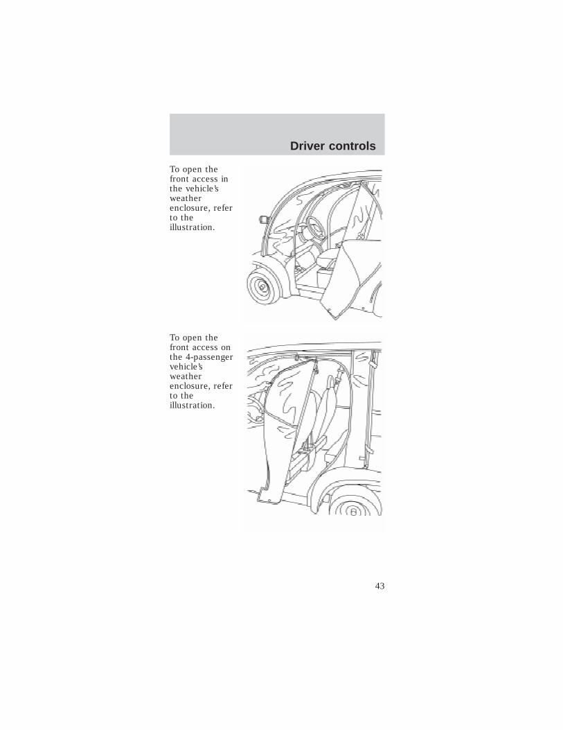
To open thefront access inthe vehicle’sweatherenclosure, referto theillustration.
To open thefront access onthe 4-passengervehicle’sweatherenclosure, referto theillustration.
Driver controls
43

StorageAfter thoroughly cleaning and completely drying theweather enclosures, you may store them in thestorage bag as follows:
1. Lay the weather enclosure panels flat on top ofeach other on a clean, smooth surface.
2. Fold the bottom fabric onto the clear plastic.
3. From the front or rear, roll it up and slide it intothe storage bag.
VEHICLE COVER (IF EQUIPPED)The vehicle cover drapes over the vehicle and isheld in place by elastic. It can be locked using acable and lock.
There are hydrogen gases around thebatteries that can explode if exposed to
flames, sparks, or lit cigarettes. The amount ofhydrogen gas is increased during battery charging.An explosion could result in personal injury orvehicle damage.
Do not charge the batteries with theweather enclosure closed or the vehicle
cover in place. A build-up of hydrogen gas canresult which can cause an explosion. The chargingarea should be well ventilated.
Driver controls
44
SEATING
Head restraints
The head restraints on the front and rear seats arein a fixed position and cannot be adjusted orremoved.
Front seat
Never adjust the driver’s seat when thevehicle is moving.
Always make sure that both front seatbottoms are latched down into place before
operating the vehicle.
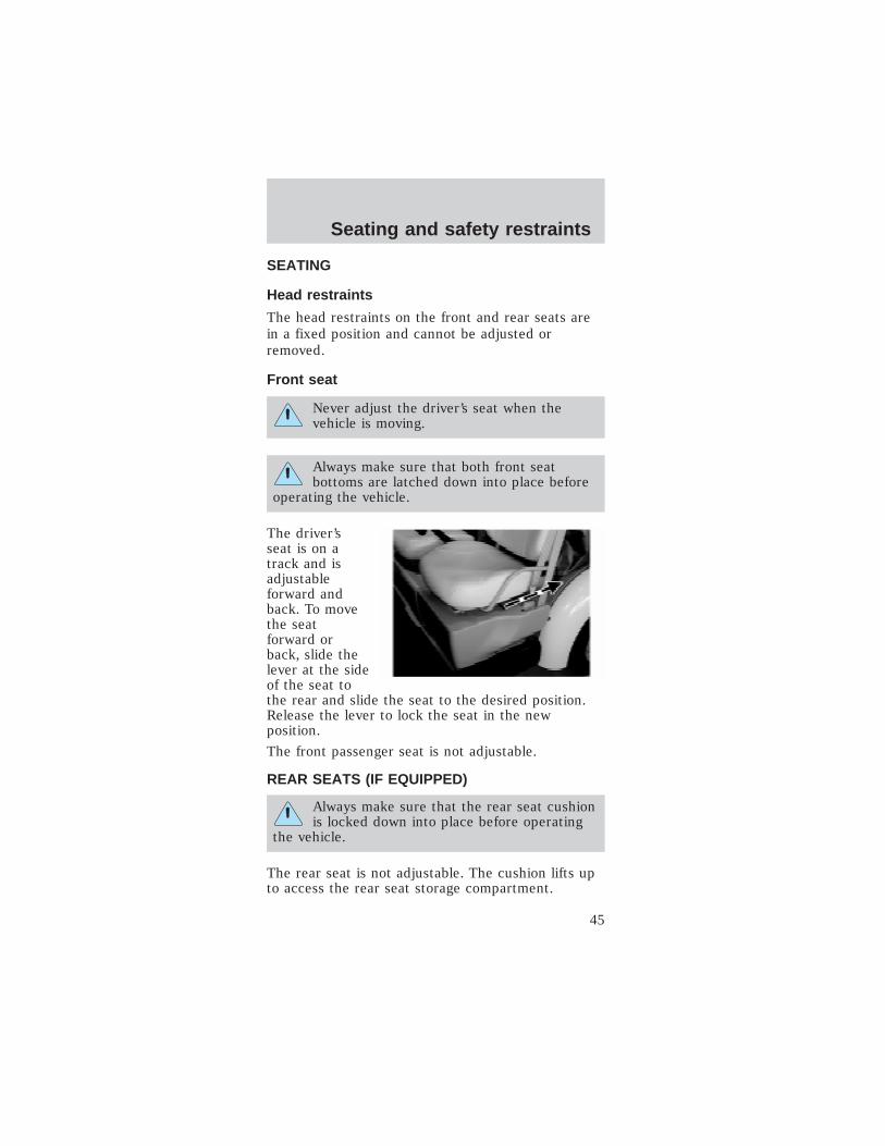
The driver’sseat is on atrack and isadjustableforward andback. To movethe seatforward orback, slide thelever at the sideof the seat tothe rear and slide the seat to the desired position.Release the lever to lock the seat in the newposition.
The front passenger seat is not adjustable.
REAR SEATS (IF EQUIPPED)
Always make sure that the rear seat cushionis locked down into place before operating
the vehicle.
The rear seat is not adjustable. The cushion lifts upto access the rear seat storage compartment.
Seating and safety restraints
45

SAFETY RESTRAINTS
Safety restraints precautions
Always make sure that both front seatbottoms are latched down into place before
operating the vehicle.
To reduce the risk of injury, make surechildren sit where they can be properly
restrained.
Never let a passenger hold a child on his orher lap while the vehicle is moving. The
passenger cannot protect the child from injury in acollision.
All occupants of the vehicle, including thedriver, should always properly wear their
safety belts.
It is extremely dangerous to ride in a cargoarea, inside or outside of a vehicle. In a
collision, people riding in these areas are morelikely to be seriously injured or killed. Do not allowpeople to ride in any area of your vehicle that isnot equipped with seats and safety belts. Be sureeveryone in your vehicle is in a seat and using asafety belt properly.
In a rollover crash, an unbelted person issignificantly more likely to die than a person
wearing a safety belt.
Seating and safety restraints
46

Each seating position in your vehicle has aspecific safety belt assembly which is made
up of one buckle and one tongue that are designedto be used as a pair. 1) Use the shoulder belt onthe outside shoulder only. Never wear the shoulderbelt under the arm. 2) Never swing the safety beltaround your neck over the inside shoulder.3) Never use a single belt for more than oneperson.
Combination lap and shoulder belts1. Insert thebelt tongue intothe properbuckle (thebuckle closestto the directionthe tongue iscoming from)until you hear asnap and feel itlatch. Makesure the tongueis securelyfastened in thebuckle.
2. To unfasten,push therelease buttonon the buckleand pull thetongue out ofthe buckle.
Seating and safety restraints
47

Vehicle sensitive mode
The vehicle sensitive mode is the normal retractormode, allowing free shoulder belt length adjustmentto your movements, and locking in response tovehicle movement. If the driver brakes suddenly orturns a corner sharply, or the vehicle receives animpact of approximately 8 km/h (5 mph) or more,the combination safety belts will lock to help reduceforward movement of the driver and passenger.
Cinch tongue mode
The front passenger and rear seat (if equipped)have cinch tongues to help install a child safety seattightly.
The cinch tongue will slide up and down the beltwebbing when the belt is in the stowed position orwhile putting safety belts on. When the cinch tongueof the lap/shoulder combination safety belt is latchedinto the buckle, the cinch tongue will allow the lapportion to become shorter, but holds the webbing inplace to keep the lap belt from becoming longer.
Before you can reach and latch a combination lapand shoulder belt having a cinch tongue into thebuckle, you may have to lengthen the lap beltportion of it.
Seating and safety restraints
48

1. To lengthenthe lap belt,pull somewebbing out ofthe shoulderbelt retractor.
2. While holdingthe webbingbelow thetongue, graspthe tip (metal portion) of the tongue so that it isparallel to the webbing and slide the tongue upward.
3. Provide enough lap belt length so that the tonguecan reach the buckle.
How to fasten the cinch tongue
1. Pull the combination lap and shoulder belt fromthe retractor so that the shoulder belt portion of thesafety belt crosses your shoulder and chest.
2. Be sure the belt is not twisted. If the belt istwisted, remove the twist.
3. Insert the belt tongue into the proper buckle foryour seating position until you hear a snap and feelit latch.
4. Make sure the tongue is securely fastened to thebuckle by pulling on the tongue.
The lap belt should fit snugly and as low aspossible around the hips, not across the
waist.
Front and rear seat occupants, includingpregnant women, should wear safety belts
for optimum protection in an accident.
Seating and safety restraints
49

Each seating position in your vehicle has aspecific safety belt assembly which is made
up of one buckle and one tongue that are designedto be used as a pair. 1) Use the shoulder belt onthe outside shoulder only. Never wear the shoulderbelt under the arm. 2) Never swing the safety beltaround your neck over the inside shoulder.3) Never use a single belt for more than oneperson.
While you are fastened in the safety belt, thecombination lap/shoulder belt with a cinch tongueadjusts to your movement. However, if you brakehard, turn hard, or if your vehicle receives an impactof 8 km/h (5 mph) or more, the safety belt will lockto help reduce your forward movement.
Safety belt extension assemblyIf the safety belt is too short when fully extended,there is a 20 cm (8 inch) safety belt extensionassembly.
Use only extensions manufactured by the samesupplier as the safety belt. Manufactureridentification is located at the end of the webbing onthe label. Also, use the safety belt extension only ifthe safety belt is too short when fully extended. Donot use extensions to change the fit of the shoulderbelt across the torso.
Safety belt maintenanceCheck the safety belt systems periodically to makesure that they work properly and are not damaged.
All safety belt assemblies, including retractors,buckles, child safety seat tether bracket assemblies(if equipped), and attaching hardware, should beinspected after any collision. Th!nk recommends thatall safety belt assemblies used in vehicles involved ina collision be replaced. However, if the collision wasminor and a qualified technician finds that the beltsdo not show damage and continue to operateproperly, they do not need to be replaced. Safety
Seating and safety restraints
50

belt assemblies not in use during a collision shouldalso be inspected and replaced if either damage orimproper operation is noted.
Failure to inspect and if necessary replacethe safety belt assembly following a collision
or in the event of a damaged or worn belt, couldresult in severe personal injuries in the event of acollision.
CHILD RESTRAINTS
Important precautions
You are required by law to use safetyrestraints for children in the United States.
If small children ride in your vehicle (generallychildren who are four years old or younger andwho weigh 18 kg [40 lbs] or less), you must putthem in safety seats made especially for children.Check your local state laws for specificrequirements regarding the safe transportation ofchildren in your vehicle.
Never let a passenger hold a child on his orher lap while the vehicle is moving. The
passenger cannot protect the child from injury in acollision.
Always follow the instructions and warningsthat come with any infant or child restraint
you might use.
Children and safety beltsIf the child is the proper size, restrain the child in asafety seat.
Children who are too large for child safety seats (asspecified by your child safety seat manufacturer)should always wear safety belts.
Seating and safety restraints
51
Moving the child closer to the center of the vehiclemay help provide a good shoulder belt fit.To improve the fit of lap and shoulder belts onchildren who have outgrown child safety seats,TH!NK Mobility recommends use of abelt-positioning booster seat that is labeled asconforming to all applicable federal motor vehiclesafety standards. Belt—positioning booster seatsraise the child and provide a shorter, firmer seatingcushion that encourages safer seating posture and abetter fit of lap and shoulder belts.A belt-positioning booster should be used if theshoulder belt rests in front of the child’s face orneck, or if the lap belt does not fit snugly on boththighs, or if the thighs are too short to let the childsit all the way back on the seat cushion when thelower legs hang over the edge of the seat cushion.You may wish to discuss the special needs of yourchild with your pediatrician.
Follow all of the important safety restraintprecautions that apply to adult passengers in yourvehicle.
Do not leave children, unreliable adults, orpets unattended in your vehicle.
SAFETY SEATS FOR CHILDREN
Child and infant or child safety seatsUse a safety seat that is recommended for the sizeand weight of the child. Carefully follow all of the
Seating and safety restraints
52
manufacturer’s instructions with the safety seat youput in your vehicle. If you do not install and use thesafety seat properly, the child may be injured in asudden stop or collision.
When installing a child safety seat:
• Use the correct safety belt buckle for that seatingposition.
• Insert the belt tongue into the proper buckle untilyou hear a snap and feel it latch. Make sure thetongue is securely fastened in the buckle.
• Keep the buckle release button pointing up andaway from the safety seat, with the tonguebetween the child seat and the release button, toprevent accidental unbuckling.
• Place seatback in upright position.
Carefully follow all of the manufacturer’sinstructions included with the safety seat
you put in your vehicle. If you do not install anduse the safety seat properly, the child may beinjured in a sudden stop or collision.
Installing child safety seats in cinch tonguecombination lap and shoulder belt seatingpositions (typical seat shown)
The belt webbing below the tongue is the lapportion of the combination lap/shoulder belt, and thebelt webbing above the tongue is the shoulder beltportion of the combination lap/shoulder belt.
Seating and safety restraints
53
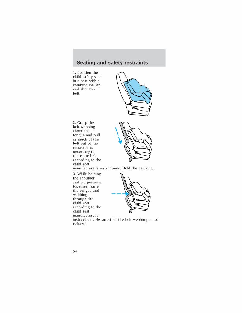
1. Position thechild safety seatin a seat with acombination lapand shoulderbelt.
2. Grasp thebelt webbingabove thetongue and pullas much of thebelt out of theretractor asnecessary toroute the beltaccording to thechild seatmanufacturer’s instructions. Hold the belt out.
3. While holdingthe shoulderand lap portionstogether, routethe tongue andwebbingthrough thechild seataccording to thechild seatmanufacturer’sinstructions. Be sure that the belt webbing is nottwisted.
Seating and safety restraints
54
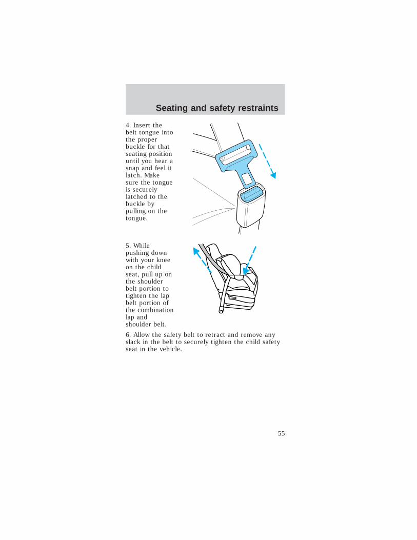
4. Insert thebelt tongue intothe properbuckle for thatseating positionuntil you hear asnap and feel itlatch. Makesure the tongueis securelylatched to thebuckle bypulling on thetongue.
5. Whilepushing downwith your kneeon the childseat, pull up onthe shoulderbelt portion totighten the lapbelt portion ofthe combinationlap andshoulder belt.
6. Allow the safety belt to retract and remove anyslack in the belt to securely tighten the child safetyseat in the vehicle.
Seating and safety restraints
55

7. Beforeplacing thechild into thechild seat,forcibly tilt thechild seatforward andback to makesure that theseat is heldsecurely inplace.
8. Check from time to time to be sure that there isno slack in the lap/shoulder belt. The shoulder beltmust be snug to keep the lap belt tight during acollision.
Attaching child safety seats with tetherstraps
Most new forward-facing child safety seats include atether strap which goes over the back of the seatand hooks to an anchoring point. Tether straps areavailable as an accessory for many older safety seats.Contact the manufacturer of your child seat forinformation about ordering a tether strap.
The optional LATCH equipped passenger seat isequipped with built-in tether strap anchors locatedbehind the seat as described below.
The tether anchor (if equipped) in your vehicle islocated at the bottom of the front passengerseatback.
Attach the tether strap only to theappropriate tether anchor as shown. The
tether strap may not work properly if attachedsomewhere other than the correct tether anchor.
Seating and safety restraints
56

1. Position thechild safety seaton the seatcushion.
2. Route thechild safety seattether strapover the back ofthe seat andbetween thehead restraintposts.
3. Locate thecorrect anchor.
Seating and safety restraints
57

4. Clip thetether strap tothe anchor asshown.
If the tether strap is clipped incorrectly, thechild safety seat may not be retained
properly in the event of a collision.
5. Refer to the Installing child safety seats incombination lap and shoulder belt seatingpositions section of this chapter for furtherinstructions to secure the child safety seat.
6. Tighten the child safety seat tether strapaccording to the manufacturer’s instructions.
If the safety seat is not anchored properly,the risk of a child being injured in a collision
greatly increases.
Seating and safety restraints
58

Attaching safety seats with LATCH (LowerAnchors and Tethers for Children) attachmentsfor child seat anchorsSome child safety seats have two rigid or webbingmounted attachments that connect to two anchorsat a certain seating position in your vehicle. Thistype of child seat eliminates the need to use safetybelts to attach the child seat. For forward-facingchild seats, the tether strap must also be attached tothe proper tether anchor. See Attaching safety seatswith tether straps in this chapter.
Your vehicle has LATCH anchors for child seatinstallation at the optional LATCH equipped frontpassenger seat.
The loweranchors forchild seatinstallation arelocated at therear section ofthe optionalLATCHequipped frontpassenger seatbetween thecushion andseat back.
Follow the child seat manufacturer’s instructions toproperly install a child seat with LATCHattachments. Two plastic LATCH guides can beobtained at no charge from any TH!NK dealer. Theysnap onto the LATCH lower anchors in the seat tohelp attach a child seat with rigid attachments. Theguides hold the seat trim away to expose the anchorand make it easier to attach some child seats.
Seating and safety restraints
59

Attach LATCH lower attachments of thechild seat only to the anchors shown.
If you install a child seat with rigid LATCHattachments, do not tighten the tether strap enoughto lift the child seat off the vehicle seat cushionwhen the child is seated in it. Keep the tether strapjust snug without lifting the front of the child seat.Keeping the child seat just touching the vehicle seatgives the best protection in a severe crash.
Each time you use the safety seat, check that theseat is properly attached to the lower anchors andtether anchor. Try to tilt the child seat from side toside. Also try to tug the seat forward. Check to seeif the anchors hold the seat in place.
If the safety seat is not anchored properly,the risk of a child being injured in a crash
greatly increases.
Seating and safety restraints
60
STARTING
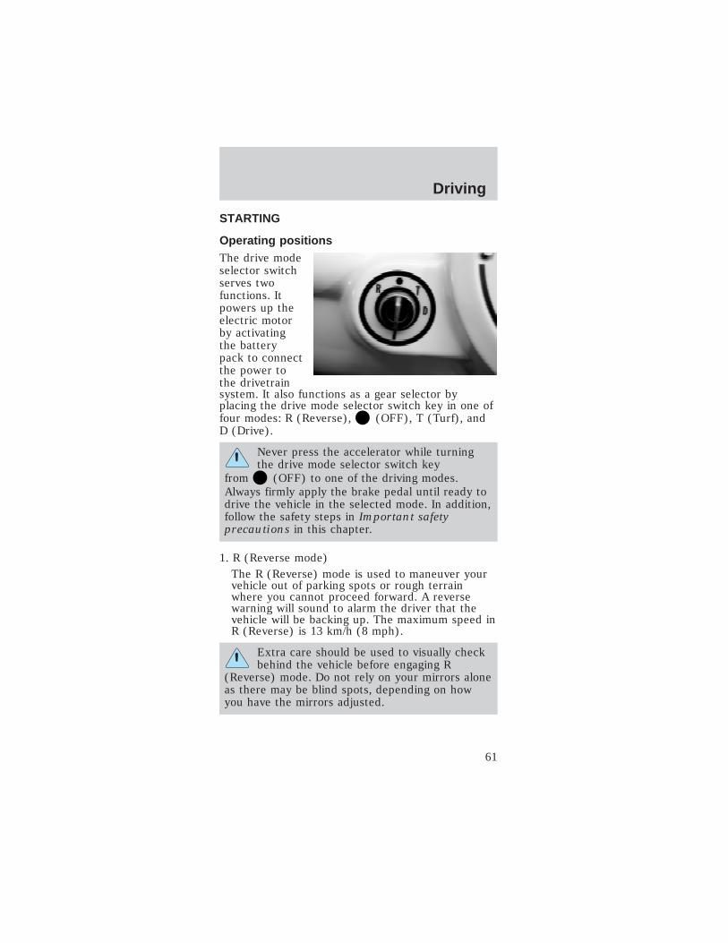
Operating positionsThe drive modeselector switchserves twofunctions. Itpowers up theelectric motorby activatingthe batterypack to connectthe power tothe drivetrainsystem. It also functions as a gear selector byplacing the drive mode selector switch key in one offour modes: R (Reverse), (OFF), T (Turf), andD (Drive).
Never press the accelerator while turningthe drive mode selector switch key
from (OFF) to one of the driving modes.Always firmly apply the brake pedal until ready todrive the vehicle in the selected mode. In addition,follow the safety steps in Important safetyprecautions in this chapter.
1. R (Reverse mode)The R (Reverse) mode is used to maneuver yourvehicle out of parking spots or rough terrainwhere you cannot proceed forward. A reversewarning will sound to alarm the driver that thevehicle will be backing up. The maximum speed inR (Reverse) is 13 km/h (8 mph).
Extra care should be used to visually checkbehind the vehicle before engaging R
(Reverse) mode. Do not rely on your mirrors aloneas there may be blind spots, depending on howyou have the mirrors adjusted.
Driving
61
2. (OFF)
The (OFF) position for the drive modeselector switch key will power down the drivetrainsystem as well as the other vehicle systems. Theparking brake should always be engaged when thekey is in this position.
3. T (Turf) mode
The T (Turf) mode is used when you are drivingon grass, sand, dirt, gravel, or pathways with loosesurfaces to provide safe handling characteristics ofyour vehicle. The maximum speed in T (Turf)mode is 24 km/h (15 mph).
4. D (Drive) mode
The D (Drive) mode will provide maximumperformance from your vehicle on the paved pathsand paved roadways. Your vehicle’s maximumspeed is 25 mph (40 km/h) and you should onlyoperate your vehicle on roadways with amaximum speed of 56 km/h (35 mph) or less.
Park brake reminderThe park brake reminder is a tone that sounds for10 seconds when the drive mode selector switch isturned to the OFF position with the parking brakenot set. It will cease to sound after 10 seconds orwhen the parking brake is engaged. During this timethe vehicle is “alive” with functional park brakereminder and the gauge will be active and backlit.After 10 seconds, the vehicle shuts down and thepark brake reminder is no longer functional.
To avoid serious injury, death, and/orproperty damage, always engage the parking
brake before leaving the vehicle.
Driving
62

Important safety precautions
Before operating the vehicle:
1. Make sure allvehicleoccupants havebuckled theirsafety belt. Formoreinformation onsafety belts andtheir properusage, refer toSeating andsafetyrestraints.
Do not drive the vehicle with the weatherenclosure side panels fully unzipped. They willdrag on the ground damaging the panels.
Any stowed panels should not contact the tiresor ground to prevent damage to the panels.
2. If equipped, make sure the weather enclosure sidepanels are not fully unzipped or, if stowed, do notcontact the ground or tires.
3. Make sure allaccessories,such asheadlamps, areturned off.
Driving
63

4. Make surethe parkingbrake is set.
5. Do not pressthe acceleratorwhile turningthe drive modeselector key.Always firmlyapply the brakepedal until youare ready todrive thevehicle in theselected mode.
To operate the vehicle:
1. Insert the key in the drive mode selector switch.
2. Depress thebrake pedal.
3. Turn the drive mode selector key to the desiredoperating mode.
4. Release the brake pedal.
Driving
64
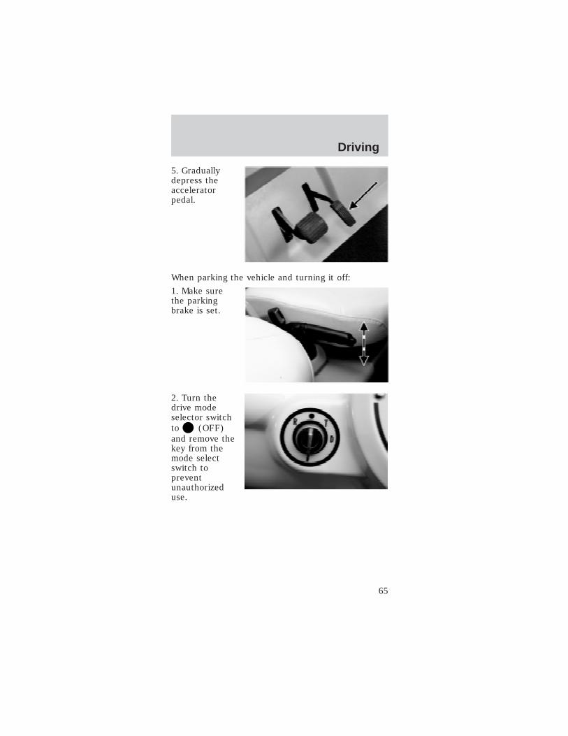
5. Graduallydepress theacceleratorpedal.
When parking the vehicle and turning it off:
1. Make surethe parkingbrake is set.
2. Turn thedrive modeselector switchto (OFF)and remove thekey from themode selectswitch topreventunauthorizeduse.
Driving
65

3. Store anyitems in thelocking glovebox and lockingrear storagecompartment.
4. Whenever possible, recharge your vehiclebatteries to maximize your range and battery life.
Energy tips
The range the vehicle can travel is affected by:
• The use of vehicle accessories
• Driving habits
• Type of tire (Turf tires reduce vehicle range)
• Weather conditions
• Age of battery pack
• Climbing steep terrain
• Driving off-road
To maximize the vehicle’s range, follow these steps:
• Keep the tires properly inflated.
• Keep payloads as light as possible.
• Avoid frequent full throttle usage.
• Maintain a steady speed while driving.
• Cruise at moderate speeds.
• Select routes that minimize the number of startsand stops encountered.
• Charge the vehicle after every use.
Driving
66
BRAKES
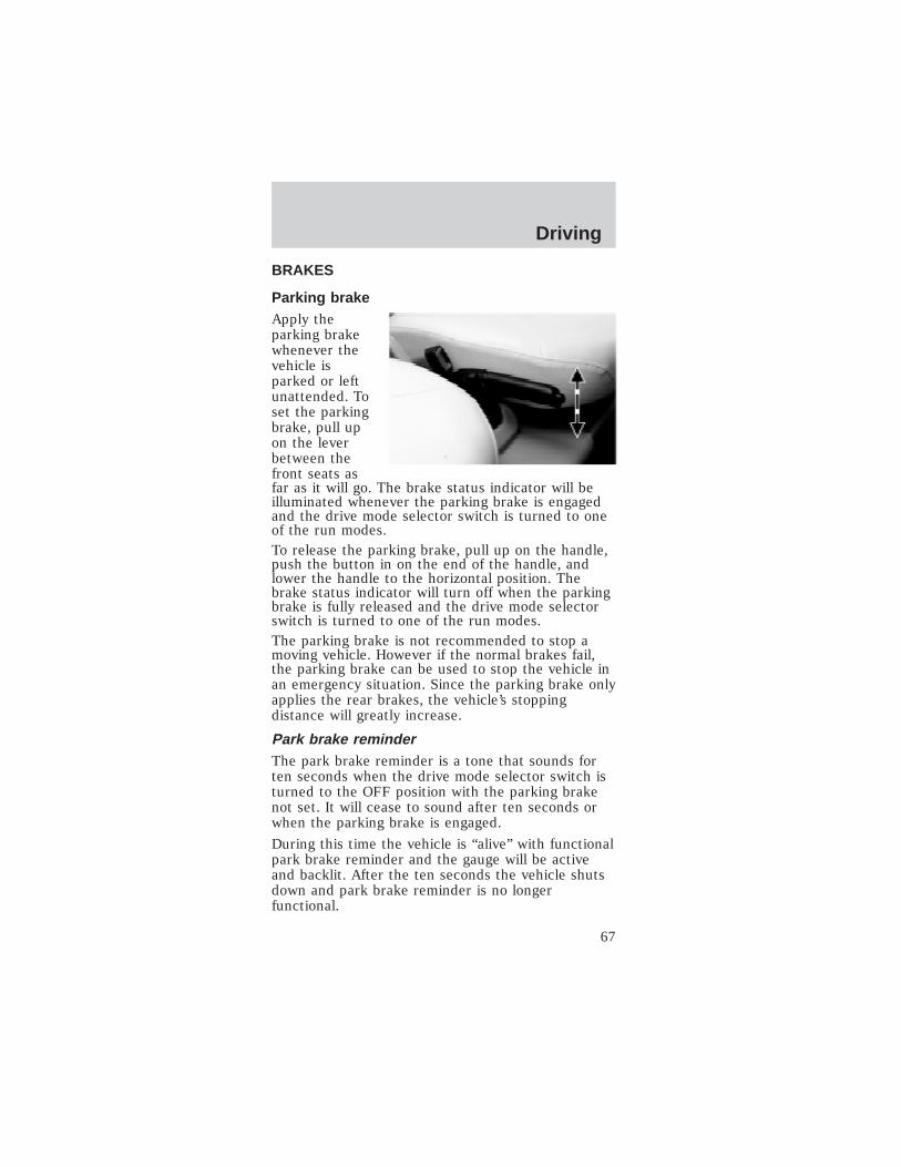
Parking brakeApply theparking brakewhenever thevehicle isparked or leftunattended. Toset the parkingbrake, pull upon the leverbetween thefront seats asfar as it will go. The brake status indicator will beilluminated whenever the parking brake is engagedand the drive mode selector switch is turned to oneof the run modes.To release the parking brake, pull up on the handle,push the button in on the end of the handle, andlower the handle to the horizontal position. Thebrake status indicator will turn off when the parkingbrake is fully released and the drive mode selectorswitch is turned to one of the run modes.The parking brake is not recommended to stop amoving vehicle. However if the normal brakes fail,the parking brake can be used to stop the vehicle inan emergency situation. Since the parking brake onlyapplies the rear brakes, the vehicle’s stoppingdistance will greatly increase.
Park brake reminderThe park brake reminder is a tone that sounds forten seconds when the drive mode selector switch isturned to the OFF position with the parking brakenot set. It will cease to sound after ten seconds orwhen the parking brake is engaged.
During this time the vehicle is “alive” with functionalpark brake reminder and the gauge will be activeand backlit. After the ten seconds the vehicle shutsdown and park brake reminder is no longerfunctional.
Driving
67
To avoid serious injury, death, and/orproperty damage, always engage the parking
brake before leaving the vehicle.
Dual circuit braking systemThe hydraulic brake system is a dual circuit design.This means if you have a brake system fluid leak orfailure, half of your brake system may remainoperational; the system will stop your vehicle, butyour stopping distance will be greatly increased.
Regenerative Braking System (RBS)
Another feature of your vehicle is the RegenerativeBraking System (RBS). The RBS is designed toutilize the vehicle’s forward motion to generateelectricity and partially recharge the batteries for anominal increase in driving range. The RBS workswhen you are not applying the accelerator. Once theaccelerator pedal is released, the vehicleautomatically and slowly decelerates. Thisdeceleration is caused by using the spinning motoras a generator to create electrical current. Thisrecharges the battery pack and slows the vehicle.The RBS works only when the vehicle is traveling at29 km/h (18 mph) or greater and the batteries areat less than 80% state of charge. When driving downhills, regenerative braking may be used to maintainspeed while recovering energy similar to the wayengine braking is typically used. When the battery isfully charged, regenerative braking is eliminated toprevent overcharging of the batteries. Regenerativebraking does not take the place of the standardfriction brakes; it only assists them.
Driving
68

Caution: If the battery pack is fully charged,RBS will not be enabled because the batterypack cannot accept the additional current. Thecontactor is designed to open if the batterypack voltage exceeds 80V. Avoid drivingsituations where you will be driving down steepgrades with a fully charged battery pack or thedrive system and RBS will shut down. Thestandard braking system is not affected butspeeds may exceed 25 mph (40 km/h). If thisshould occur, apply brakes to reduce andmaintain speeds below 25 mph (40 km/h).
Driving
69
BATTERY CHARGINGBattery charging uses 120 volt AC 15A service. TheGFCI (ground fault circuit interrupt) charge cordsupplied with your vehicle plugs directly into thecharge inlet located below and to the left of thesteering wheel. Approximately 8-10 hours areneeded to replenish a 20% (one bar showing)charged battery pack. Charge the vehicle wheneverthe state of charge is less than 80% (four barsshowing) to maximize your travel range and prolongthe battery life.The battery charger receives 120 volt AC 15A powerfrom an external standard grounded 3-prong outletand converts it to DC energy. The battery chargeronly operates when a GFCI charger cord is pluggedinto your vehicle. If the battery charger detects anypresence of AC current, your vehicle cannot bestarted or driven.Caution: If you allow your vehicle to sit inconditions of -6°C (20°F) or less with a state ofcharge of 20% (one bar showing on gauge) orless, the batteries could freeze. Allowing thebatteries to freeze may cause permanentdamage to the batteries and permanentlyreduce their capacity. In cold conditions, placethe vehicle in an area greater than 0°C (32°F)and allow it to warm up before charging. Nevercharge the vehicle if the batteries may befrozen. Allow the batteries to warm above 0°C(32°F) first, then charge.
There are gases around the batteries thatcan explode if exposed to flames, sparks, or
lit cigarettes. The amount of gas is increasedduring battery charging. An explosion could resultin personal injury or vehicle damage.
Do not charge the batteries with theweather enclosure closed or the vehicle
cover in place. A build up of hydrogen gas canresult which can explode. The charging areashould be well ventilated.
Charging
70
Caution: Do not allow the vehicle to remain ina discharged state, as batteries may bepermanently damaged and vehicle range will bedecreased.
To recharge your vehicle batteries:
Use only the GFCI cord supplied with the vehicle. Ifthe GFCI cord does not fit the receptacle, have aqualified electrician install the proper outlet.
Note: The outlet must be properly installed andgrounded in accordance with all local codes andordinances.
1. Park your vehicle within GFCI charger cord lengthof a 120 volt AC 15A grounded 3-prong wall outlet.
2. Place the drive mode selector switch in the OFFposition, remove the key and set the parking brake.
Note: Make sure the power point (if equipped) isnot in use.
Note: Make sure that the inlet is clean and dry.
Note: Never use a plug adapter or an extensioncord.
3. Insert the male end of the GFCI charger cord in a120 volt AC grounded receptacle. Verify that thepower indicator light on the GFCI cord is on.
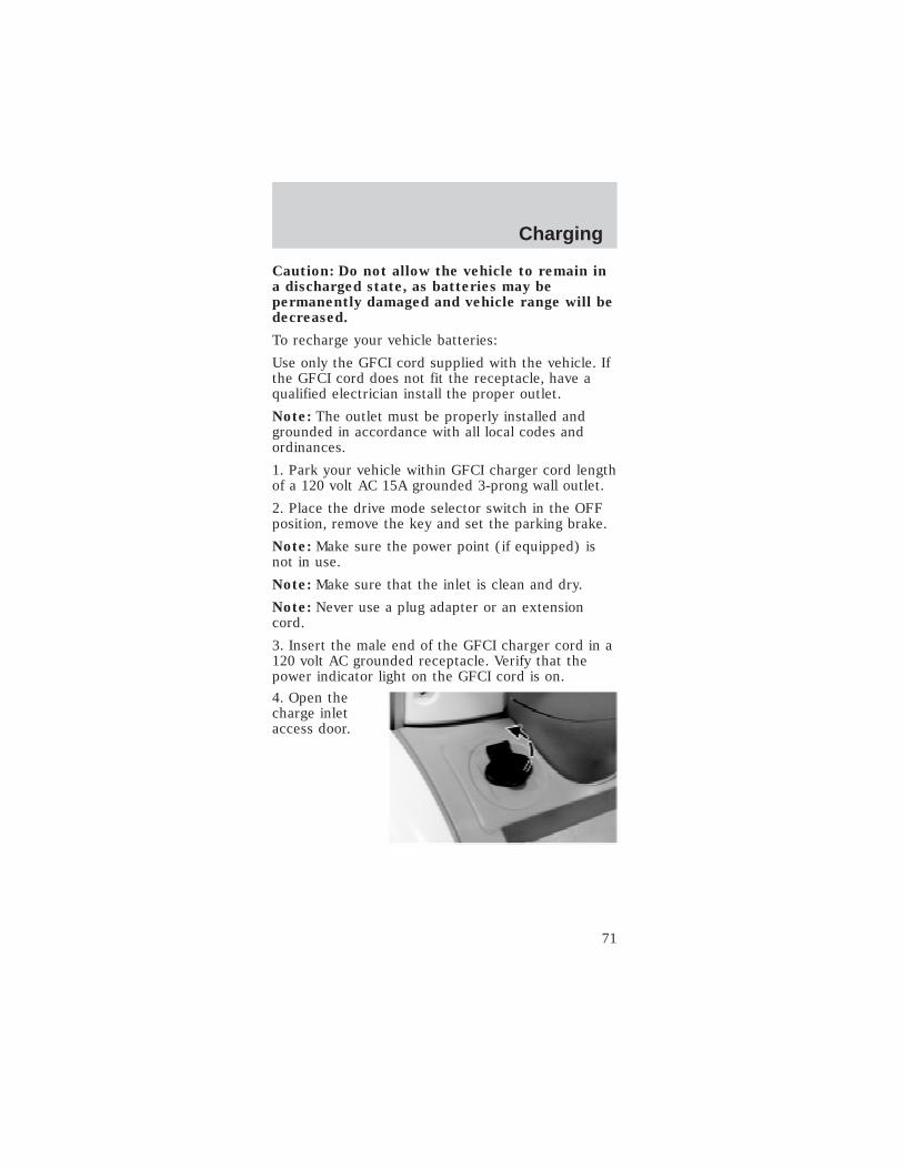
4. Open thecharge inletaccess door.
Charging
71
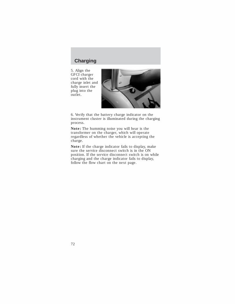
5. Align theGFCI chargercord with thecharge inlet andfully insert theplug into theoutlet.
6. Verify that the battery charge indicator on theinstrument cluster is illuminated during the chargingprocess.
Note: The humming noise you will hear is thetransformer on the charger, which will operateregardless of whether the vehicle is accepting thecharge.
Note: If the charge indicator fails to display, makesure the service disconnect switch is in the ONposition. If the service disconnect switch is on whilecharging and the charge indicator fails to display,follow the flow chart on the next page.
Charging
72

After properly connecting the vehicle to thereceptacle, the charger will initiate a four stagecharging process. In the first stage, the battery istested. Further charging is prohibited if the chargerdiscovers a fault. If the battery passes, the chargerdetermines the appropriate charging rate, dependingupon the voltage of the battery pack, and chargesthe battery pack. In the second and third stages, thevoltage is regulated, and charging is completed. Thebattery is maintained at the full state of charge inthe fourth stage. If the vehicle is left on, the charger
Plu
g G
FC
I co
rd in
to w
ork
ing
120
V A
C o
utle
t us
ing
pro
ced
ure
po
sted
nex
t to
cha
rge
inle
t o
n ve
hicl
eo
r o
n p
p. 6
5-66
of
your
Ow
ner'
s M
anua
l. U
se a
circ
uit
cap
able
of
carr
ying
15A
with
out
tri
pp
ing
the
circ
uit
bre
aker
.
ST
AR
T-S
et p
arki
ng b
rake
Is t
he b
atte
ry c
harg
ein
dic
ato
r sh
ow
ing
on
the
gau
ge?
Bat
teri
es a
re c
harg
ing
. Wai
t at
leas
t 12
hour
s fo
r co
mp
lete
cha
rge.
Veh
icle
is n
ow
ful
ly c
harg
ed
Co
ntac
t d
eale
r fo
r se
rvic
e. B
atte
ry
pac
k vo
ltag
e m
ay b
e to
o lo
w.
Wha
t 10
min
utes
and
chec
k ag
ain.
Is b
atte
ry c
harg
e in
dic
ato
r sh
ow
ing
?
Unp
lug
co
rd f
rom
ve
hicl
e an
d
turn
dri
ve m
od
e se
lect
or
switc
h to
dri
ve. I
s th
e b
atte
ry o
utlin
e so
lid a
nd a
ll fiv
e b
ars
pre
sent
on
the
gau
ge?
Is t
his
the
first
tim
e th
roug
h th
is c
harg
e cy
cle?
YE
S
YE
S
YE
SY
ES
Co
ntac
t d
eale
r fo
r se
rvic
e. B
atte
ry P
ack
volta
ge
may
be
too
low
.
NO
NO
NO
NO
Charging
73

will automatically reinitiate a new charge cycle every28 days.
To stop charging of your vehicle batteries:
1. Push theTEST button onyour GFCIcharger cord.Verify that theindicator lighton the GFCI isOFF.
2. Disconnect the GFCI charger cord from the walloutlet.
3. Disconnect the GFCI charger cord from thecharge inlet.
4. Store the cord in a safe and dry location.
Charging
74
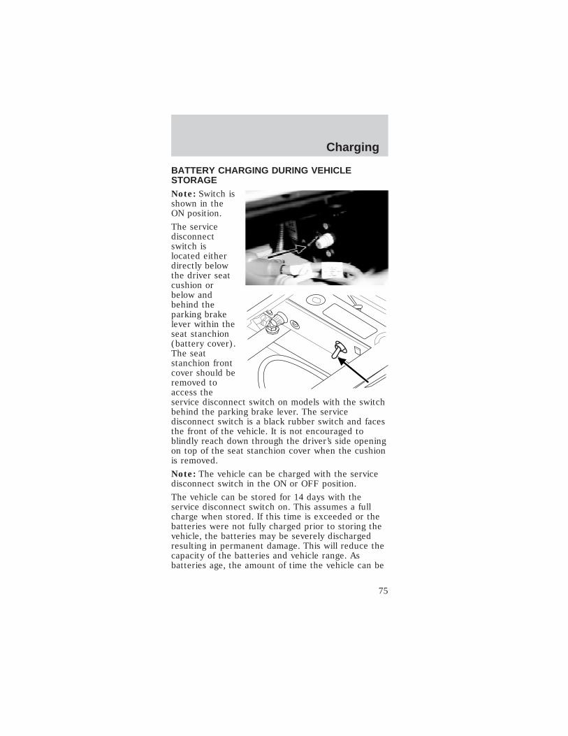
BATTERY CHARGING DURING VEHICLESTORAGENote: Switch isshown in theON position.
The servicedisconnectswitch islocated eitherdirectly belowthe driver seatcushion orbelow andbehind theparking brakelever within theseat stanchion(battery cover).The seatstanchion frontcover should beremoved toaccess theservice disconnect switch on models with the switchbehind the parking brake lever. The servicedisconnect switch is a black rubber switch and facesthe front of the vehicle. It is not encouraged toblindly reach down through the driver’s side openingon top of the seat stanchion cover when the cushionis removed.
Note: The vehicle can be charged with the servicedisconnect switch in the ON or OFF position.
The vehicle can be stored for 14 days with theservice disconnect switch on. This assumes a fullcharge when stored. If this time is exceeded or thebatteries were not fully charged prior to storing thevehicle, the batteries may be severely dischargedresulting in permanent damage. This will reduce thecapacity of the batteries and vehicle range. Asbatteries age, the amount of time the vehicle can be
Charging
75
stored without turning the service disconnect switchoff will decrease.
The vehicle can be stored with the servicedisconnect switch off for six months if starting witha full charge; however, the vehicle should be chargedmonthly if possible. With the service disconnectswitch in the OFF position, there is a minimal drawfrom the vehicle components. The batteryself-discharge determines the storage time. This isless than 5% per month at temperatures between4°C and 21°C (40°F and 70°F). Self-dischargeincreases slightly at higher temperatures. If thebatteries are nearly discharged, they may freeze at0°C (32°F) or below. This will cause severe damagethat may even cause leakage of the electrolyte.
Note: Leaving the charger cord connected duringstorage is preferred.
Charging
76

HAZARD FLASHER SWITCHUse the hazardflashers only inan emergencyto warn trafficof your vehiclebreakdown, orapproachingdanger, etc. Thehazard flasherscan be operatedwith the drivemode selector switch in all positions. The hazardflasher switch is located on top of the steeringcolumn, right behind the steering wheel. Depress theswitch to activate the hazard lights. To turn off thehazard lights, depress the switch again.
With the hazardflasher switchdepressed, bothturn signal indicators will flash on the instrumentpanel cluster.
12V FUSES
Change a fuseIf electricalcomponents arenot working,check thecircuit fuse firstto see if it isblown. You can identify a blown fuse by the brokenwire in the center of the fuse between two prongs.
Always replace a fuse with one that has thespecified amperage rating. Using a fuse with
a higher amperage rating can cause severe wiredamage and could start a fire.
15
Roadside emergencies
77

Central fuses
To access the fuses under the hood:
1. Unlock andremove thehood.
2. Inspect thefuse for thecircuit with amalfunction andreplace the fuseif necessary.Always use thesame amperagerated fuse as areplacement.See the chartfor the fuse amperage ratings and circuitdescriptions.
To access the fuses under the passenger seat:
3. Remove thepassenger seatcushion, andinspect the fusefor the circuitwith amalfunction andreplace the fuseif necessary.Always use thesame amperagerated fuse as a replacement. See the chart for thefuse amperage ratings and circuit descriptions.
65
4
Roadside emergencies
78

Fuse
Location
Fuse Amp
Rating
Fuse
color
Circuit
description
1 20A Yellow Horn, Flasher,Brake
2 20A Yellow Lights
3 10A Red Wiper, Washer,Gauge
4 30A (Slo-B lo) — DC/DC
5 30A — Charger
6 10A — Control (motorcontroller/gauge)
4. After replacing the fuse, check the component toverify that it is operating properly.5. Install and lock the hood or install the passengerseat cushion.Power point fuse (if equipped)The powerpoint (ifequipped)requires a 20Afuse.
CHANGING THE TIRESYour vehicle is not equipped with a spare tire.Should your tires require service take you vehicle toan authorized Dealer.
Jacking
Lifting instructionsDamage to the suspension or steering linkagesystem components may occur whenpositioning the jack pad. The pad should bepositioned carefully to ensure maximumcontact under the frame.
When lifting a vehicle, care should be taken toposition the vehicle so that the jack pads donot damage the halfshafts, steering linkage or
Roadside emergencies
79

suspension arms. Damage to suspension and/orsteering linkage components may occur.
To lessen risk of personal injury, do not putany part of your body under the vehicle whilejacking.
Your vehicle is constructed with many aluminumcomponents which may be damaged if:
• The proper jack lifting points are not utilized.
Roadside emergencies
80
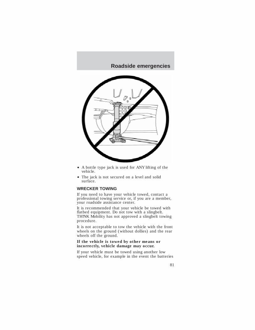
• A bottle type jack is used for ANY lifting of thevehicle.
• The jack is not secured on a level and solidsurface.
WRECKER TOWINGIf you need to have your vehicle towed, contact aprofessional towing service or, if you are a member,your roadside assistance center.It is recommended that your vehicle be towed withflatbed equipment. Do not tow with a slingbelt.TH!NK Mobility has not approved a slingbelt towingprocedure.
It is not acceptable to tow the vehicle with the frontwheels on the ground (without dollies) and the rearwheels off the ground.
If the vehicle is towed by other means orincorrectly, vehicle damage may occur.
If your vehicle must be towed using another lowspeed vehicle, for example in the event the batteries
Roadside emergencies
81

are discharged, the service disconnect switch shouldbe switched to the OFF position.
Note: Switch isshown in theON position.
The servicedisconnectswitch is locatedeither directlybelow the driverseat cushion orbelow andbehind theparking brakelever within theseat stanchion(battery cover).The seatstanchion frontcover should beremoved toaccess theservice disconnect switch on models with the switchbehind the parking brake lever. The service disconnectswitch is a black rubber switch and faces the front ofthe vehicle. It is not encouraged to blindly reach downthrough the driver’s side opening on top of the seatstanchion cover when the cushion is removed.
Each corner ofyour vehicle isequipped with atow/tie downhook. Both frontor both rear towhooks must beused for towingor recoveryoperations.Additionally, when shipping or transporting, all fourtow/tie down hooks must be used to prevent damage.
Roadside emergencies
82

WASHING YOUR VEHICLE
Do not take your vehicle to an automatic car
wash or use a high power spray hose to wash
your vehicle.
Wash your vehicle regularly with cold or lukewarmwater. Never use strong detergents or soaps. Alwaysuse a clean sponge and plenty of water to avoidscratching the dirt into your vehicle’s finish. To avoidspotting, do not wash your vehicle in direct sunlight.
Any chemicals or foreign material such as tar, treesap, industrial fallout, and bird droppings should becleaned off your vehicle as soon as possible.
When adding brake fluid to the brake reservoir,
avoid spilling fluid onto the vehicle’s plastic
panels, including the instrument panel. If brake
fluid is spilled on any surface, wash it
immediately with soap and water to prevent
cracking, discoloration, or other damage.
The windshield and mirrors can be cleaned using ahousehold commercial glass cleaner and soft,lint-free cloth.
UNDERBODY
Flush the complete underside of the vehicleregularly. Inspect for damage.
WAXING YOUR VEHICLEWaxing your vehicle on a regular basis will reduceminor scratches and surface damage.
Wax the vehicle when water stops beading on thesurface. This could be every three or four months,depending on operation.
Use Meguiars polish #8232 found at local auto partsstores. Use a cleaning fluid with a clean cloth toremove any foreign material, such as dirt or insects,before waxing your vehicle. Use tar remover toremove any tar spots.
Cleaning
83
REPAIRING SCRATCHESThe specific process that is used to remove minorscratches should be performed by an authorizedDealer.
CLEANING WHEELSWash with the same detergent used to wash thebody of the vehicle. Do not use acid-based oralcohol-based wheel cleaners, steel wool, fuel orstrong detergents. Never use abrasives that willdamage the finish of special wheel surfaces. Use atar remover to remove grease and tar.
CLEANING EXTERIOR LAMPSWash with the same detergent used to wash thevehicle exterior. If necessary, use a tar remover,such as Ford Extra Strength Tar and Road OilRemover (B7A-19520–AA).To avoid scratching the lamps, do not use a drypaper towel, chemical solvents or abrasive cleaners.
CLEANING THE INSTRUMENT PANELClean the instrument panel with a damp cloth, thendry it with a dry cloth.
CLEANING THE GAUGE ASSEMBLYClean the gauge assembly with a damp cloth, thendry it with a dry cloth.
CLEANING AND MAINTAINING THE SAFETYBELTSClean the safety belts with a mild soap solution ofthe type recommended for cleaning upholstery orcarpets.
Do not use bleach, dye or any other solvent toclean the belts, as these actions may weakenthe belt webbing.
Check the safety belt system periodically to makesure there are no nicks, tears, or cuts. If the vehiclehas been involved in an accident, refer to theSeating and safety restraints chapter.
Cleaning
84

CLEANING THE INTERIORRemove dust and loose dirt with a whisk broom or avacuum cleaner. Remove fresh spots immediately. Donot use household or glass cleaners. These agentscan stain and discolor the fabric. Use a mild soapand water solution, if necessary.
CLEANING THE WEATHER ENCLOSURERinse any surface dirt off before cleaning theweather enclosure. Use a mild soapy cool/warmwater solution and a clean soft cloth to the clean theclear plastic window sections of the weatherenclosure. Use plenty of water to keep the clearplastic wet. DO NOT use a strong detergent, bleach,or any abrasive cleaners to clean any part of theweather enclosure.
To clean the colored vinyl portions of the weatherenclosure, use a mild soapy cool/warm watersolution and a soft brush, sponge, or cloth. Rinse theweather enclosure thoroughly and air dry completelybefore using or storing it. DO NOT USE heat guns,or hair dryers. DO NOT put the weather enclosureinto a washing machine or dryer of any kind. DONOT IRON.
Cleaning
85

BATTERIES
Flooded batteries must be refilled with
distilled or demineralized water to avoid
internal damage.
For longer, trouble-free operation, keep the top ofthe batteries clean and dry. Also, make certain thebattery cables are always tightly fastened to thebattery terminals. The battery terminals require aspecific torque setting, so if any cable appears to beloose, contact your TH!NK dealer for service.
If you see any corrosion on the batteries orterminals, push the rubber boots back and clean theterminals with a wire toothbrush. You can neutralizethe acid with a solution of baking soda and water.
Caution: If you allow your vehicle to sit inconditions of -6°C (20°F) or less with a state ofcharge of 20% (one bar showing on gauge) orless, the batteries could freeze. Allowing thebatteries to freeze may cause permanentdamage to the batteries and permanentlyreduce their capacity. In cold conditions, placethe vehicle in an area greater than 0°C (32°F)and allow it to warm up before charging. Nevercharge the vehicle if the batteries may befrozen. Allow the batteries to warm above 0°C(32°F) first, then charge.
Caution: Do not park and leave the vehiclewith discharged batteries. The batteries coulddischarge to the point where damage couldoccur and the battery charger will not charge.The vehicle will have to be taken to anauthorized TH!NK dealer if this happens.
Batteries normally produce explosive gaseswhich can cause personal injury. Therefore,
do not allow flames, sparks or lighted substancesto come near the battery. When working near thebattery, always shield your face and protect youreyes. Always provide proper ventilation.
Maintenance and specifications
86

When lifting a plastic-cased battery,excessive pressure on the end walls could
cause acid to flow through the vent caps, resultingin personal injury and/or damage to the vehicle orbattery. Lift the battery with a battery carrier orwith your hands on opposite corners. Do not lift abattery by the terminal posts, or internal damagemay result.
Keep batteries out of reach of children.Batteries contain sulfuric acid. Avoid contact
with skin, eyes or clothing. Shield your eyes whenworking near the battery to protect againstpossible splashing of acid solution. In case of acidcontact with skin or eyes, flush immediately withwater for a minimum of 15 minutes and getprompt medical attention. If acid is swallowed, calla physician immediately.
• Alwaysdispose ofautomotivebatteries in aresponsiblemanner.Follow yourlocalauthorizedstandards fordisposal. Callyour local authorized recycling center to find outmore about recycling automotive batteries.
Remove all jewelry, rings, bracelets, andchains that may come into contact with the
battery terminals or wiring.
Battery posts, terminals and relatedaccessories contain lead and lead
compounds. Wash hands after handling.
LE
AD
RE
TU
RN
RECYCLE
Maintenance and specifications
87

Flooded type batteries
If your vehicle is equipped with “flooded” batteries,the battery cells need to be checked and havedistilled or demineralized water added as required.The batteries in your vehicle are located under thefront seats. They are 12 volt, 6 cell batteries.
The battery water reminder indicator in theinstrument cluster will illuminate to remind you tocheck the water level in the batteries. Perform thismaintenance in a well-ventilated area that is dry andwell lit.
To check the water level in your batteries:
1. Pull straightup on the frontof the front seatcushions torelease theclips.
2. Remove thetwo center pushpins.
Maintenance and specifications
88

3. From bothsides of thevehicle, removethe two pushpins. (Driverside shown;passenger sidesimilar)
4. From bothsides of thevehicle, removefour bolts frombeside the seatframe. (Driverside shown;passenger sideis similar.)
Do not touch the battery terminals withyour hands or a metal object. Also, do not
lay any tools on the batteries and never connectone battery terminal with another with any tool ormetal object laid across the top of the battery.
This vehicle contains a high voltageelectrical system. Serious injury, death,
and/or property damage may result if this vehicleis not properly used, charged or serviced as statedin this manual. Read this owner’s guide prior touse, charging, or servicing this vehicle. Do notdrill, cut, or modify any part of this vehicle, ashigh voltage wiring is present. Do not use jumpercables. Only charge this vehicle with an approvedGFCI cord as stated in Battery charging.
Maintenance and specifications
89
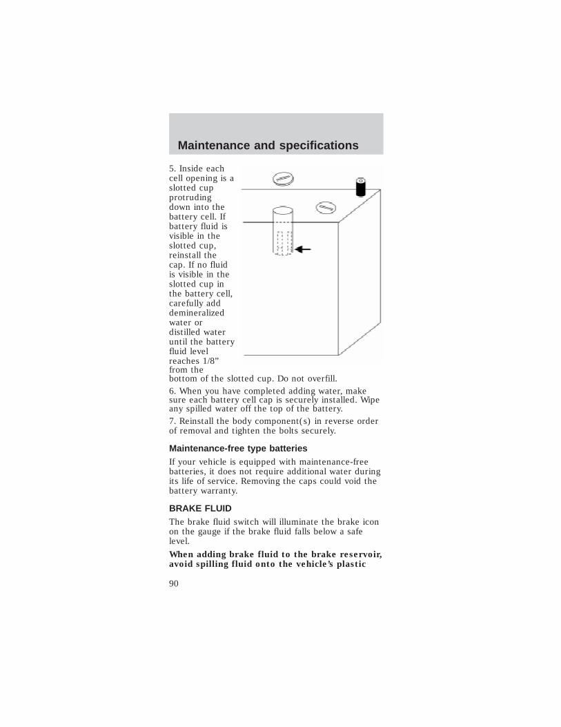
5. Inside eachcell opening is aslotted cupprotrudingdown into thebattery cell. Ifbattery fluid isvisible in theslotted cup,reinstall thecap. If no fluidis visible in theslotted cup inthe battery cell,carefully adddemineralizedwater ordistilled wateruntil the batteryfluid levelreaches 1/8”from thebottom of the slotted cup. Do not overfill.6. When you have completed adding water, makesure each battery cell cap is securely installed. Wipeany spilled water off the top of the battery.7. Reinstall the body component(s) in reverse orderof removal and tighten the bolts securely.
Maintenance-free type batteriesIf your vehicle is equipped with maintenance-freebatteries, it does not require additional water duringits life of service. Removing the caps could void thebattery warranty.
BRAKE FLUIDThe brake fluid switch will illuminate the brake iconon the gauge if the brake fluid falls below a safelevel.
When adding brake fluid to the brake reservoir,avoid spilling fluid onto the vehicle’s plastic
Maintenance and specifications
90
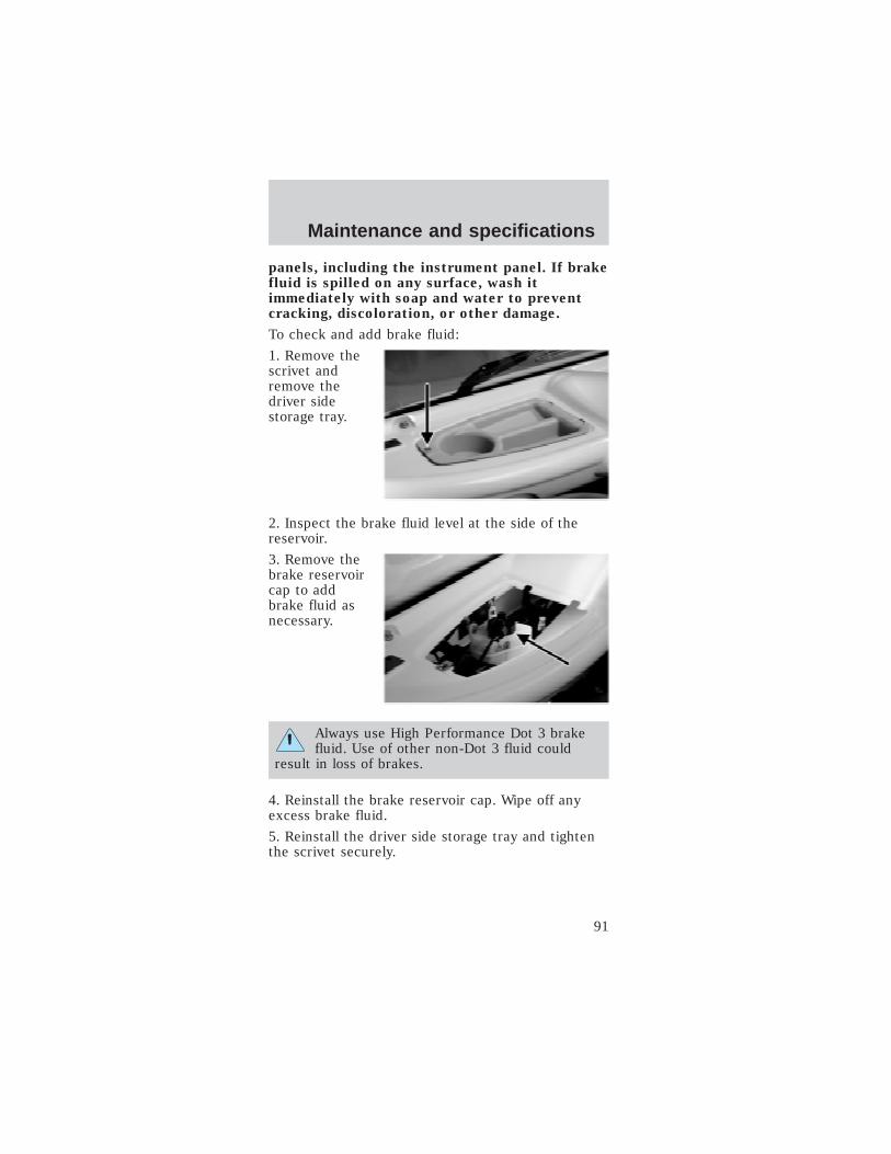
panels, including the instrument panel. If brakefluid is spilled on any surface, wash itimmediately with soap and water to preventcracking, discoloration, or other damage.
To check and add brake fluid:
1. Remove thescrivet andremove thedriver sidestorage tray.
2. Inspect the brake fluid level at the side of thereservoir.
3. Remove thebrake reservoircap to addbrake fluid asnecessary.
Always use High Performance Dot 3 brakefluid. Use of other non-Dot 3 fluid could
result in loss of brakes.
4. Reinstall the brake reservoir cap. Wipe off anyexcess brake fluid.
5. Reinstall the driver side storage tray and tightenthe scrivet securely.
Maintenance and specifications
91
SERVICING YOUR TIRES
Checking the tire pressure
• Use an accurate tire pressure gauge.
• Check the tire pressure when tires are cold, afterthe vehicle has been parked for at least one houror has been driven less than 5 km (3 miles).
• Adjust tire pressure to recommendedspecifications found on the Certification Labellocated on the roof panel towards the rear of thevehicle.
Improperly inflated tires can affect vehiclehandling and can fail suddenly, possibly
resulting in loss of vehicle control.
Tire rotation
Because your vehicle’s tires perform different jobs,they often wear differently. To make sure your tireswear evenly and last longer, rotate them as indicatedin the scheduled maintenance guide. If you noticethat the tires wear unevenly, have them checked.
• Four tirerotation
Maintenance and specifications
92

Replacing the tiresReplace thetires when thewear band isvisible throughthe tire treads.
Your TH!NK neighbor is equipped with eitherstandard street or turf tires. The load rating forthese tires is 470 kg (1036 lbs). These tires alsocomply with the requirements of Federal motorvehicle safety standards (FMVSS) 109 and FMVSS119, and carry a “DOT” marking, indicating they maybe used for highway service. TH!NK recommendsthat any replacement tires you purchase carry theDOT marking, showing they are approved forhighway service. DO NOT replace with non-OE tiresdesignated “NHS” (Not for Highway Service). OEtires are available through your TH!NK dealer.
Tires that are larger or smaller than your vehicle’soriginal tires may also affect the accuracy of yourspeedometer.
PART NUMBERS
Component Part number
Battery (standard) 10655–AA
Battery (optional) 10655–BA
Tire (Street tire) 1531–AA
Tire (Turf tire) 1531–BA
Windshield wiper blade 17528–AA
Maintenance and specifications
93

REFILL CAPACITIES
Fluid Ford Part
Name
Application Capacity
Brake fluid MotorcraftHighPerformanceDOT 3MotorVehicleBrake Fluid
All Fill to line onreservoir
Gearbox 80W90 All .69 quarts(.65 Liters)
LUBRICANT SPECIFICATIONS
Items Ford Part
Name or
equivalent
Ford Part
Number
Ford
Specification
Batteryterminallubricant
Electricalgrease
F8AZ-19G208–AA WSB-M1C239–A
Brakefluid
MotorcraftHighPerformanceDOT 3 MotorVehicle BrakeFluid
C6AZ-19542-AB ESA-M6C25-Aand DOT 3
Seattracks
Multi-PurposeGrease
DOAZ-19584-AAorF5AZ-19G209-AA
ESA-M1C93-BorESR-M1C159-A
Lockcylinders
Penetratingand LockLubricant
Motorcraft XL-1 None
Gearbox 80W90PremiumRear AxleLubricant
XY-80W90–QL WSP-M2C197–A
Halfshaftsplines
CV JointGrease (HighTemp.)
E43Z-19590-A ESP-M1C207-A
Maintenance and specifications
94

Items Ford Part
Name or
equivalent
Ford Part
Number
Ford
Specification
Wind-shieldwasherfluid
Ultra-clearWindshieldWasherConcentrate
ZC-18–A orZC-18–B
ESR-M17P5-A
PERIODIC SERVICE SCHEDULE
Regular
IntervalItem Service
Daily serviceby owner
Batteries Charge batteries (as often aspossible).
Monthlyservice byowner orqualifiedtechnician
Batteries Check electrolyte level. Adddistilled water ordemineralized water asnecessary per maintenanceand service manual.
Wash battery tops and cleanterminals with bakingsoda/water solution. Dispose
of waste water properly.
Tires Check air pressure and adjustas necessary.
Generalvehicle
Wash battery compartmentand underside of vehicle.Dispose of waste water
properly.
Semi-annualservice by aqualifiedtechnicianonly
Brake system Check brake shoes (replace ifnecessary).
Brake linkage and pivots
Lubricate brake slides.
Check brake cables fordamage; replace as required.
Electricalwiring andconnections
Check for tightness anddamage.
Front wheelalignment
Check and adjust as required.
Maintenance and specifications
95

Regular
IntervalItem Service
Annualservice byqualifiedtechnician
Batteries Perform battery tests permaintenance and servicemanual.
Check for proper battery terminal tightness.
Inspect the brake pushrod locknut fortightness.
Check/fill gearbox fluid to the amountindicated in refill capacities chart.
Inspect front wheel bearings (repack asnecessary).
16093kilometers(10,000miles)
Tires Rotate the tires
VEHICLE DIMENSIONS
Vehicle
dimensions
2 passenger
mm (in)
2 passenger
Wagon mm
(in)
4 passenger
mm (in)
(1) Overalllength
2,642 (104) 3,082(121.35)
2, 898(114.1)
(2) Overallwidth
1,433 (56.4) 1,433 (56.4) 1, 433 (56.4)
(3) Overallheight
1,720 (67.7) 1,720 (67.7) 1, 720 (67.7)
(4)Wheelbase
1,726 (67.9) 1,980 (77.9) 1, 980 (77.9)
(5) Track -Street tires
1,274 (50.1) 1,274 (50.1) 1,274 (50.1)
(5) Track -Turf tires
1,234 (48.6) 1,234 (48.6) 1,234 (48.6)
Maintenance and specifications
96

IDENTIFYING YOUR VEHICLE
Certification label (typical label shown)The NationalHighway TrafficSafetyAdministrationRegulationsrequire that aCertificationlabel be affixedto a vehicle andprescribe wherethe Certificationlabel may belocated. TheCertificationlabel is locatedon roof paneltowards the rear of the vehicle.
Vehicle identification numberThe vehicleidentificationnumber is on ametal taglocated on thedriver sideinstrumentpanel.
Maintenance and specifications
97

In order to help you service your TH!NK neighbor,please have the following information available whencontacting a Customer Relationship Center:• Your telephone number (home and business).• The name of the dealer and the city where the
dealership is located.• The year and make of your vehicle.• The date of vehicle purchase.• The current odometer reading.
• The vehicle identification number (VIN).
If you still have a complaint involving a warrantydispute, you may wish to contact the DisputeSettlement Board (U.S.).
In some states (in the U.S.) you must directly notifyTH!NK Mobility in writing before pursuing remediesunder your state’s warranty laws. TH!NK Mobility isalso allowed a final repair attempt in some states.
In the United States, a warranty dispute must besubmitted to the Dispute Settlement Board beforetaking action under the Magnuson-Moss WarrantyAct, or to the extent allowed by state law, beforepursuing replacement or repurchase remediesprovided by certain state laws. This dispute handlingprocedure is not required prior to enforcing statecreated rights or other rights which are independentof the Magnuson-Moss Warranty Act or statereplacement or repurchase laws.
THE DISPUTE SETTLEMENT BOARD(U.S. ONLY)The Dispute Settlement Board is:
• an independent, third-party arbitration programfor warranty disputes
• available free to owners and lessees of qualifyingTH!NK vehicles
The Dispute Settlement Board may not be availablein all states. TH!NK Mobility reserves the right tochange eligibility limitations, modify procedures
Customer assistance
98

and/or to discontinue this service without notice andwithout incurring obligations per applicable statelaw.
What kinds of cases does the Board review?
Unresolved warranty repair concerns or vehicleperformance concerns as on TH!NK vehicles whichare within the terms of any applicable written newvehicle warranty are eligible for review, except thoseinvolving:
• a non-TH!NK product
• a non-TH!NK dealership
• sales disputes between customer and dealerexcept those associated with warranty repairs orconcerns with the vehicle’s performance asdesigned
• a request for reimbursement of consequentialexpenses unless a service or product concern isbeing reviewed
• items not covered by the New Vehicle LimitedWarranty (including maintenance and wear items)
• alleged personal injury/property damage claims
• cases currently in litigation
• vehicles not used primarily for family, personal orhousehold purposes (except in states where theDispute Settlement Board is required to reviewcommercial vehicles)
• vehicles with non-U.S. warranties
Concerns are ineligible for review if the New VehicleLimited Warranty has expired at receipt of yourapplication and, in certain states eligibility isdependent upon the customer’s possession of thevehicle.
Eligibility may differ according to state law. Forexample, see the unique brochures for California,West Virginia, Georgia and Wisconsinpurchasers/lessees.
Customer assistance
99

Board membershipThe Board consists of:• three consumer representatives• a TH!NK dealership representativeConsumer candidates for Board membership arerecruited and trained by an independent consultingfirm. The dealership Board member is chosen fromTH!NK dealership management, recognized for theirbusiness leadership qualities.
What the Board needsTo have your case reviewed you must complete theapplication in the DSB brochure and mail it to theaddress provided on the application form. Somestates will require you to use certified mail, withreturn receipt requested.
Your application is reviewed and, if it is determinedto be eligible, you will receive an acknowledgmentindicating:
• The file number assigned to your application.
• The toll-free phone number of the DSB’sindependent administrator.
Your dealership and a TH!NK Mobility representativewill then be asked to submit statements.
To properly review your case, the Board needs thefollowing information:
• Legible copies of all documents and maintenanceor repair orders relevant to the case.
• The year, make, model, and Vehicle IdentificationNumber (VIN) listed on your vehicle ownershiplicense.
• The date of repair(s) and mileage at the time ofoccurrence(s).
• The current mileage.
• The name of the dealer(s) who sold or servicedthe vehicle.
• A brief description of your unresolved concern.
Customer assistance
100

• A brief summary of the action taken by thedealer(s) and TH!NK Mobility.
• The names (if known) of all the people youcontacted at the dealership(s).
• A description of the action you expect to resolveyour concern.
You will receive a letter of explanation if yourapplication does not qualify for Board review.
Oral presentationsIf you would like to make an oral presentation,indicate YES to question 6 on the application. Whileit is your right to make an oral presentation beforethe Board, this is not a requirement and the Boardwill decide the case whether or not an oralpresentation is made. An oral presentation may berequested by the Board as well.
Making a decisionBoard members review all available informationrelated to each complaint, including oralpresentations, and arrive at a fair and impartialdecision. Board review may be terminated at anytime by either party.
Every effort is made to decide the case within 40days of the date that all requested information isreceived by the Board. Since the Board generallymeets once a month, it may take longer for theBoard to consider some cases.
After a case is reviewed, the Board mails you adecision letter and a form on which to accept orreject the Board’s decision. The decisions of theBoard are binding on TH!NK (and, in some cases, onthe dealer) but not on consumers who are free topursue other remedies available to them under stateor federal law.
Customer assistance
101
To request a DSB Brochure/Application
For a brochure/application, speak to your dealer orwrite/call to the Board at the followingaddress/phone number:
Dispute Settlement BoardP.O. Box 5120Southfield, MI 48086–51201–800–428–3718
You may also contact the North American CustomerRelationship Center at 1-800-392-3673 (Ford), TDDfor the hearing impaired: 1-800-232-5952 or bywriting to the Center at the following address:
Ford Motor CompanyCustomer Relationship Center16800 Executive Plaza DriveP.O. Box 6248Dearborn, Michigan 48121
ORDERING ADDITIONAL OWNER’SLITERATURE
To order the publications in this portfolio, contactHelm, Incorporated at:
HELM, INCORPORATEDP.O. Box 07150Detroit, Michigan 48207
Or call:
For a free publication catalog, order toll free:1-800-782-4356
Monday-Friday 8:00 a.m. - 6:00 p.m. EST
(Items in this catalog may be purchased by creditcard holders only.)
Customer assistance
102

REPORTING SAFETY DEFECTS (U.S. ONLY)If you believethat yourvehicle has adefect which could cause a crash or could causeinjury or death, you should immediately inform theNational Highway Traffic Safety Administration(NHTSA) in addition to notifying TH!NK Mobility.
If NHTSA receives similar complaints, it may openan investigation, and if it finds that a safety defectexists in a group of vehicles, it may order a recalland remedy campaign. However, NHTSA cannotbecome involved in individual problems betweenyou, your dealer, or TH!NK Mobility.
To contact NHTSA, you may either call the AutoSafety Hotline toll-free at 1–800–424–9393 (or366–0123 in the Washington D.C. area) or write to:
NHTSAU.S. Department of TransportationWashington, D.C. 20590
You can also obtain other information about motorvehicle safety from the Hot-line.
Customer assistance
103

Your satisfaction is our #1 goal. If you havequestions or concerns with your TH!NK vehicle, wesuggest you follow these steps:
1. Contact your Sales Representative or ServiceAdvisor at your selling/servicing dealership.
2. If the inquiry or concern remains unresolved,contact the Sales Manager or Service Manager at thedealership.
3. If the inquiry or concern cannot be resolved atthe dealership level, please contact the TH!NKMobility Customer Relationship Center.
In the United States:
TH!NK Mobility
Customer Relationship Center
16800 Executive Plaza Drive
P.O. Box 6248
Dearborn, MI 48121
1–800–252–4221
TDD for hearing impaired:
1–800–232–5952
INTRODUCTIONFord Motor Company and your selling dealerthank you for selecting one of our quality products.Our commitment to you and your TH!NK vehiclebegins with quality protection and service.
When you need warranty repairs, your selling dealerwould like you to return to it for that service, butyou may also take your TH!NK vehicle to anotherTH!NK dealership authorized for warranty repairs.Certain warranty repairs require special trainingthough, so not all dealers are authorized to performall warranty repairs. That means that, depending onthe warranty repair needed, the TH!NK vehicle mayneed to be taken to another dealer. If a particulardealership cannot assist you, then contact theCustomer Relationship Center at 1–800–252–4221.
Warranty information
104

This chapter explains in detail the warrantycoverages that apply to your 2002–model TH!NKvehicle. If you bought a previously owned2002–model TH!NK vehicle, you are eligible for anyremaining warranty coverages.
Ford Motor Company or Ford Motor VehicleAssurance Company (a subsidiary of Ford MotorCompany, The American Road, Dearborn, MI 48121)provides the New TH!NK Vehicle LimitedWarranty. See the section titled The New TH!NKVehicle Limited Warranty for your 2002–modelTH!NK vehicle in this chapter.
If you are interested in knowing whether thewarranty coverage is provided by Ford MotorCompany or Ford Motor Vehicle AssuranceCompany, call the Customer Relationship Center at1–800–252–4221. The warranty coverage you receiveand your dealer’s handling of any warranty coveredrepair will be the same regardless of the warrantyprovider.
IMPORTANT INFORMATION YOU SHOULDKNOW
If you need customer assistanceYour TH!NK dealer is available to assist you with allyour automotive needs. Please follow the proceduresoutlined at the beginning of this chapter.
Know when your warranty beginsYour Warranty Start Date is the day you takedelivery of your new TH!NK vehicle or the day it isfirst put into service (for example, as a dealerdemonstrator), whichever occurs first.
Check your TH!NK vehicleWe try to check TH!NK vehicles carefully at theassembly plant and the dealership, and we usuallycorrect any damage to paint, body panels,upholstery, or other appearance items. Butoccasionally something may slip past us, and a
Warranty information
105

customer may find that a vehicle was damagedbefore he or she took delivery. If you see anydamage when you receive your vehicle, notify yourdealership within one week.
Maintain your TH!NK vehicle properlyYour glove compartment contains an Owner’sGuide which indicates the scheduled maintenancerequired for your TH!NK vehicle. Propermaintenance guards against major repair expensesresulting from neglect or inadequate maintenance,and may help increase the value you receive whenyou sell or trade your Think vehicle.It is your responsibility to make sure that all of thescheduled maintenance is performed and that thematerials used meet TH!NK engineeringspecifications. Failure to perform scheduledmaintenance as specified in the Owner’s Guide willinvalidate warranty coverage on parts affected bythe lack of maintenance. Make sure that receipts forcompleted maintenance work are retained with thevehicle and confirmation of maintenance work isalways entered in your Owner’s Guide.
Your TH!NK dealership has factory-trainedtechnicians who can perform the requiredmaintenance using genuine TH!NK parts. Thedealership looks forward to meeting your everyservice need to maximize your satisfaction with yourTH!NK vehicle.
Who pays for warranty repairs?You will not be charged for covered warranty repairsmade during the warranty periods for Bumper toBumper, Safety Restraint, or Corrosion.
You will not be charged for repairs to defectivebatteries during the first 12 months after thewarranty start date.
Your battery is covered on a customer-participationbasis after the first 12 months in service.
Some states have mandated alternate time coverageperiods for parts of your vehicle (e.g. seatbelts).
Warranty information
106

Some states and/or local governments may require atax on a portion of warranty repairs. Whereapplicable law allows, the tax must be paid by you,the owner of the vehicle.
During the Bumper to Bumper Warranty period,dealers may receive instructions to provide no-cost,service-type improvements-not originally included inyour Owner’s Guide- intended to increase youroverall satisfaction with your vehicle.
Sometimes TH!NK may offer a special adjustmentprogram to pay all or part of the cost of certainrepairs beyond the terms of the applicable warranty.Check with your dealer or call 1–800–252–4221 tolearn whether any adjustment program is applicableto your TH!NK vehicle. Please have your vehicleidentification number available.
THE NEW TH!NK VEHICLE LIMITED WARRANTYFOR YOUR 2002–MODEL TH!NK VEHICLEYour NEW TH!NK VEHICLE LIMITED WARRANTYgives you specific legal rights. You may have otherrights that vary from state to state. The New TH!NKVehicle Limited Warranty is the only expresswarranty applicable to your TH!NK vehicle. NeitherFord Motor Company or Ford Motor VehicleAssurance Company assumes nor authorizes anyoneto assume for it any other obligation or liability inconnection with your TH!NK vehicle or thiswarranty.
Ford Motor Company, Ford Motor Vehicle AssuranceCompany and your dealer are not responsible forany time that you lose, for any inconvenience youmight be caused, for the loss of your transportation,or for any other incidental or consequential damagesyou may have.
You may have some implied warranties. For example,you may have:
• an implied warranty of merchantability (that theTH!NK vehicle is reasonably fit for the generalpurpose for which it was sold); or
Warranty information
107

• an implied warranty of fitness for a particularpurpose (that the TH!NK vehicle is suitable foryour special purposes.)
These implied warranties are limited, to the extentallowed by law, to the time period covered by thewritten warranties, or to the applicable time periodprovided by state law, whichever period is shorter.
Some states do not allow Ford Motor Company orFord Motor Vehicle Assurance Company to limit howlong an implied warranty lasts or to exclude or limitincidental or consequential damages, so thelimitation and exclusions described above may notapply to you.
Note: If you are an eligible U.S. owner and have awarranty concern unresolved by your dealer, youmay use the services of the Dispute SettlementBoard. See the Dispute settlement board in theCustomer assistance chapter.
Quick Reference: Warranty CoverageThis chart gives a general summary of your warrantycoverage provided by Ford Motor Company or FordMotor Vehicle Assurance Company under the NewTH!NK Vehicle Limited Warranty. Please refer tothe description of warranty coverage for morespecific information.
For more details on coverage, see What is coveredand What is not covered in this chapter.
Type of Coverage Years in Service Miles
Bumper to Bumper 3 years Unlimited miles
Battery 3 years* Unlimited miles
Safety Restraint 5 years Unlimited miles
Corrosion 5 years Unlimited miles
* Customer participation (pro-rated coverage) after 12months (regardless of miles driven). See details of batterycoverage for percentage Ford will pay.
Warranty information
108

What is coveredThe New TH!NK Vehicle Limited Warrantycoverage is provided by Ford Motor Company orFord Motor Vehicle Assurance Company, a subsidiaryof Ford Motor Company. These coverages includeBumper to Bumper Coverage, Battery Coverage,Safety Restraint Coverage, and Corrosion Coverage.
Bumper to Bumper CoverageUnder your New TH!NK Vehicle Limited Warranty,Bumper to Bumper Coverage begins at the warrantystart date and lasts for three years regardless ofmiles driven. During this coverage period, authorizedTH!NK dealers will repair, replace, or adjust all partson your TH!NK vehicle that are defective infactory-supplied materials or workmanship. Items orconditions that are not covered by the New TH!NKVehicle Limited Warranty are described in What’snot covered in this chapter.When making warranty repairs on your TH!NKvehicle, the dealer will use TH!NK parts orremanufactured or other parts that are authorizedby TH!NK. In certain instances, TH!NK mayauthorize repairs at other than TH!NK dealerfacilities.
Battery CoverageUnder your New TH!NK Vehicle Limited Warranty,full battery coverage begins on the warranty startdate and lasts for 12 months. During this timeperiod, Ford Motor Company or Ford Motor VehicleAssurance Company warrants your TH!NK vehicle’sbattery against defects in factory supplied materialsor workmanship. After the first 12 months in service(until the 36 month regardless of miles driven), adefective battery will be replaced on acustomer-participation basis:
• For the 13th month through 18th month inservice, Ford Motor Company will pay 60% of thecost of the replacement battery.
• For the 19th month through 24th month ofservice, Ford Motor Company will pay 40% of thecost of the replacement battery.
Warranty information
109

• For the 25th month through 30th month ofservice, Ford Motor Company will pay 20% of thecost of the replacement battery.
• For the 31st month through 36th month ofservice, Ford Motor Company will pay 10% of thecost of the replacement battery.
The percentage Ford Motor Company will pay isapplied to the present suggested retail price of thenew replacement battery for your TH!NK vehicle.
Labor required to test and replace a defectivebattery has full coverage under the terms of theBattery Warranty. Towing, if needed, is coveredunder the terms of the Roadside AssistanceProgram. See Roadside Assistance in this chapter.
Safety Restraint CoverageUnder your New TH!NK Vehicle Limited Warranty,Safety Restraint Coverage begins at the warrantystart date and lasts for five years regardless of milesdriven.
During this coverage period, Ford Motor Companyor Ford Motor Vehicle Assurance Company warrantsyour TH!NK vehicle’s safety belts against defects infactory-supplied materials or workmanship.
Corrosion CoverageUnder your New TH!NK Vehicle Limited Warranty,Corrosion Coverage begins at the warranty start dateand covers body panels against corrosion due to adefect in factory-supplied materials or workmanship.Corrosion Coverage (which lasts for 5 years,regardless of miles driven) only applies if thecorrosion causes perforation (holes) in body panels.
If corrosion does not cause perforation (holes), andis not the result of usage and/or environmentalconditions, paint damage is covered under the termsof the Bumper to Bumper Warranty (3 yearsregardless of miles driven).
For damage caused by airborne material(environmental fallout) — where there is no factory
Warranty information
110
related defect involved and therefore no warranty,our policy is to cover paint damage due to airbornematerial for 12 months.
What is not coveredDamaged caused by:
• accidents, collision or objects striking the TH!NKvehicle
• theft, vandalism, or riot• freezing• fire or explosion• misusing the TH!NK vehicle, such as driving over
curbs, overloading or racing• altering or modifying the TH!NK Vehicle —
including the body, chassis, or components —after the TH!NK Vehicle leaves TH!NK’s Mobility’scontrol
• non-TH!NK parts installed after the TH!NK vehicleleaves TH!NK’s Mobility’s control
• tampering with the TH!NK vehicle
• using contaminated or improper fluids
• customer-applied chemicals or accidental spills
• driving through water deep enough to causeelectrical system damage
Damage caused by use and/or the environmentYour New TH!NK Vehicle Limited Warranty does notcover surface rust and deterioration of paint, trim,upholstery, and other appearance items that resultfrom use and/or exposure to the elements. Here areexamples:
• stone chips, scratches (some examples are onpaint and glass)
• dings, dents
• cuts, burns, punctures or tears
• road salt, tree sap
• bird and bee droppings
Warranty information
111
• lightning, hail• windstorm• earthquake• water or flood
Damage caused by improper maintenanceYour New TH!NK Vehicle Limited Warranty does notcover damage caused by failure to maintain theTH!NK vehicle, improperly maintaining the TH!NKvehicle, or using the wrong part, oil, lubricants, orfluids. See the Maintenance and specificationschapter for the correct fluid types and levels and forproper ways to maintain your TH!NK vehicle.
Maintenance/wearYour New TH!NK Vehicle Limited Warranty does notcover:
1. parts and labor needed to maintain the TH!NKvehicle; and
2. the replacement of parts due to normal wear andtear.
You, as the owner, are responsible for these items.Examples are:
• lubricants, other fluids
• brake linings/pads
• tire rotation
• cleaning/polishing
• wiper blades
Tire wear or damageNormal wear or worn-out tires are not covered bythe New TH!NK Vehicle Limited Warranty. Roadhazard damage such as cuts, snags, bruises, bulgesand impact breaks (potholes and curbs) are notcovered. Any damage caused by a puncture or tirerepair is not covered. In addition, damage fromimproper inflation or alignment, tire chains, racing,spinning (as when stuck in snow or mud), impropermounting or dismounting is not covered.
Warranty information
112

Other items and conditions not coveredYour New TH!NK Vehicle Limited Warranty does notcover:• non-Ford parts of your TH!NK vehicle, for
example, parts (including glass) installed by bodybuilders or manufacturers other than Ford MotorCompany
• TH!NK vehicles that have ever been labeled orbranded as “dismantled” “fire,” “flood,” “junk,”“rebuilt,” “reconstructed,” or “salvaged”; this willvoid the New TH!NK Vehicle Limited Warranty
• TH!NK vehicles that have been determined to bea “total loss” by an insurance company; this willvoid the New TH!NK Vehicle Limited Warranty
Time limits on coverage• After the first 12 months in service, wheel
alignment and tire balancing are not coveredunless required by a warranty repair.
ROADSIDE SERVICE ASSISTANCE
Roadside Service AssistanceYour vehicle is covered by the complimentary FordRoadside Assistance Program (unless you are drivinga daily rental unit). Under this program Ford willcover:• towing to the nearest TH!NK dealership, or towing
to your selling dealership if within 60 milesThe Roadside Assistance Program is separate fromthe New TH!NK Vehicle Limited Warranty, but theprogram’s time period runs concurrently withBumper to Bumper Warranty Coverage (three yearsregardless of miles driven). If you need towing afterBumper to Bumper coverage has ended, Ford canarrange roadside assistance and charge your creditcard unless the problem is covered by anotherTH!NK warranty. Ford will pay the tow charge underthe other warranty.
For emergency roadside assistance, call1–800–252–4221, 24 hours a day, 365 days ayear.
Warranty information
113
For daily rental units that must be towed because acovered part has failed during the Bumper toBumper warranty period, Ford will cover towing tothe nearest Ford Motor Company dealership.
STATE WARRANTY ENFORCEMENT LAWSThese state laws — sometimes called “lemon laws”— allow owners to receive a replacement TH!NKvehicle or a refund of the purchase price, undercertain circumstances. The laws vary from state tostate.
To the extent your state law allows, Ford MotorCompany requires that you first send us a writtennotification of any defects or non-conformities thatyou have experienced with your TH!NK vehicle.(This will give us the opportunity to make anyneeded repairs before you pursue the remediesprovided by your state’s law.)
In all other states where not specifically required bystate law, Ford Motor Company requests that yougive us the written notice.
Send your written notification to:
Ford Motor Company
Customer Relationship Center
16800 Executive Plaza Drive
P.O. Box 6248
Dearborn, MI 48121
Warranty information
114
A
Audio system(see Radio) ................ 30
Automatic transaxlefluid, refillcapacities ................. 94fluid, specification .. 94
Auxiliary powerpoint ........................... 28
B
Ball and clubwasher ....................... 31
Batteries .................... 86
Batteries - floodedtype ............................ 88
Batteries - maintenancefree ............................. 90
Brakesfluid, checking andadding ...................... 90fluid, refillcapacities ................. 94fluid,specifications .......... 94lubricantspecifications .......... 94parking .................... 67
Brakes - dual circuitbrake system ............. 68
Brakes - regenerativebrake system ............. 68
Break-in period ........... 2
C
Capacities for refillingfluids .......................... 94
Certification Label .... 97
Changing a tire ......... 79
Charging ........ 67, 70, 75
Child safetyrestraints ................... 51
child safety belts .... 51
Child safety seats ...... 52attaching with tetherstraps ....................... 56in front seat ............ 53in rear seat .............. 53LATCH ..................... 59
Cleaning your vehicleexterior lamps ......... 84instrumentcluster lens .............. 84instrument panel .... 84interior ..................... 85safety belts .............. 84washing .................... 83waxing ..................... 83wheels ...................... 84
Coolantrefill capacities ........ 94specifications .......... 94
Cooler ........................ 32
Cupholder(s) ............. 27
Customer AssistanceOrdering additionalowner’sliterature ............... 102The DisputeSettlement Board ... 98
Index
115

E
Enginelubricationspecifications .......... 94refill capacities ........ 94
Engine oilrefill capacities ........ 94specifications .......... 94
F
Floor mats ................. 30Fluid capacities ......... 94Fuel
capacity ................... 94Fuses .................... 77–78
G
Gauges ......................... 4Golf rack .................... 29
H
Hazard flashers ......... 77Head restraints ......... 45Headlamps ................. 12
aiming ...................... 14bulb specifications .. 22replacing bulbs ....... 15turning on and off .. 12
I
Ignition ....................... 61Infant seats (seeSafety seats) ............. 52
J
Jack ............................ 79
positioning ............... 79
K
Keyspositions of theignition .................... 61
L
Lampsbulb replacementspecificationschart ........................ 22headlamps ............... 12replacingbulbs ............ 15, 19–21
Lane change indicator(see Turn signal) ...... 14
Lights, warning andindicator ...................... 4
Limited warranty .... 107
Lubricantspecifications ............. 94
M
Maintenance andCare ...................... 95–96
Mirrors ....................... 28side view mirrors(manual) ................. 28
Motorcraft parts ........ 93
P
Parts (seeMotorcraft parts) ...... 93
Index
116

Power steeringfluid, refillcapacity ................... 94fluid,specifications .......... 94
R
Radio .......................... 30
S
Safety belts(see Safetyrestraints) ............ 46–48
Safety defects,reporting .................. 103
Safetyrestraints ............. 46–48
cleaning thesafety belts ........ 50, 84extensionassembly .................. 50for adults ................. 48for children ............. 51
Safety seats forchildren ...................... 52
Sand and seedbottle .......................... 30
Scorecard holder ....... 30
Seat belts (seeSafety restraints) ...... 46
Seats .......................... 45child safety seats .... 52
Specification chart,lubricants ................... 94
Starting yourvehicle .................. 61, 63
Sunroof(moonroof) ................ 25
Sweater basket .......... 33
Sweater net ............... 33
T
Tires ........................... 92checking thepressure ................... 92replacing .................. 93rotating .................... 92
Tires - servicing ........ 92
Transaxlefluid, refillcapacities ................. 94lubricantspecifications .......... 94
Trunk expander ........ 34
Turn signal ................ 14
V
Vehicle cover ............. 44
Vehicle dimensions ... 96
Vehicle IdentificationNumber (VIN) ........... 97
W
Warning lights(see Lights) ................. 4
Warrantycoverage .................. 108
Warrantyenforcement laws .... 114
Warrantyinformation ...... 104–106
Index
117

Washer fluid .............. 24Waxing yourvehicle ........................ 83Weatherenclosure ....... 34, 41, 44Windows
rear wiper/washer ... 23
Windshield washer fluidand wipers
checking andcleaning ................... 24operation ................. 23
Wrecker towing ......... 81
Index
118