01MY Prius Emergency Response Guide EN TCI...
17
Gasoline-Electric Hybrid
-
Upload
vuonghuong -
Category
Documents
-
view
217 -
download
0
Transcript of 01MY Prius Emergency Response Guide EN TCI...

Gasoline-Electric Hybrid
-ii- -iii-
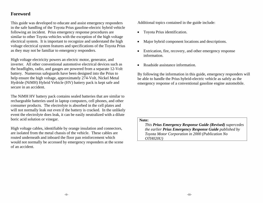
Foreword This guide was developed to educate and assist emergency responders in the safe handling of the Toyota Prius gasoline-electric hybrid vehicle following an incident. Prius emergency response procedures are similar to other Toyota vehicles with the exception of the high voltage electrical system. It is important to recognize and understand the high voltage electrical system features and specifications of the Toyota Prius as they may not be familiar to emergency responders. High voltage electricity powers an electric motor, generator, and inverter. All other conventional automotive electrical devices such as the headlights, radio, and gauges are powered from a separate 12-Volt battery. Numerous safeguards have been designed into the Prius to help ensure the high voltage, approximately 274-Volt, Nickel Metal Hydride (NiMH) Hybrid Vehicle (HV) battery pack is kept safe and secure in an accident. The NiMH HV battery pack contains sealed batteries that are similar to rechargeable batteries used in laptop computers, cell phones, and other consumer products. The electrolyte is absorbed in the cell plates and will not normally leak out even if the battery is cracked. In the unlikely event the electrolyte does leak, it can be easily neutralized with a dilute boric acid solution or vinegar. High voltage cables, identifiable by orange insulation and connectors, are isolated from the metal chassis of the vehicle. These cables are routed underneath and inboard the floor pan reinforcement which would not normally be accessed by emergency responders at the scene of an accident.
Additional topics contained in the guide include: Toyota Prius identification. Major hybrid component locations and descriptions. Extrication, fire, recovery, and other emergency response
information. Roadside assistance information. By following the information in this guide, emergency responders will be able to handle the Prius hybrid-electric vehicle as safely as the emergency response of a conventional gasoline engine automobile. Note:
This Prius Emergency Response Guide (Revised) supercedes the earlier Prius Emergency Response Guide published by Toyota Motor Corporation in 2000 (Publication No OTH020U)

-iv- -v-
(BLANK PAGE)
Table of Contents Page About the Prius 1 Prius Identification 3 Hybrid Component Locations & Descriptions 7 Gasoline-Electric Hybrid Vehicle Operation 9 Hybrid Vehicle (HV) Battery Pack and Auxiliary Battery 11 High Voltage Safety 13 SRS Airbags and Seat Belt Pretensioners 15 Emergency Response 17 Extrication 17 Fire 21 Overhaul 22 Recovery/Recycling NiMH HV Battery Pack 22 Spills 23 First Aid 23 Submersion 24 Roadside Assistance 25

-1- -2-
About the Prius The Toyota Prius is a gasoline-electric hybrid vehicle sold in North America since May 2000. Gasoline-electric hybrid means the vehicle contains a gasoline engine and an electric motor for power. Two energy sources are stored on board the vehicle:
1. Gasoline stored in the fuel tank for the gasoline engine. 2. Electricity stored in a high voltage Hybrid Vehicle (HV) battery
pack for the electric motor. The result of combining these two power sources is increased fuel economy and reduced emissions. The gasoline engine also powers an electric generator to recharge the battery pack; so, unlike a pure all electric vehicle, the Prius never needs to be recharged from an external electric power source. Depending on the driving conditions one or both sources are used to power the vehicle. The following illustrations demonstrate how the Prius operates in various driving modes. On light acceleration at low speeds, the vehicle is powered by the
electric motor. The gasoline engine is shut off. During normal driving the vehicle is powered mainly by the
gasoline engine. The gasoline engine is also used to recharge the battery pack.
During full acceleration, such as climbing a hill, both the gasoline
engine and the electric motor power the vehicle. During deceleration, such as braking, the vehicle regenerates the
kinetic energy from the front wheels to produce electricity that recharges the battery pack.
While the vehicle is stopped, the gasoline engine and electric motor
are off, however the vehicle remains on and operational.

-3- -4-
Prius Identification In appearance, the Prius is similar to a compact 4-door sedan. Exterior, interior, and engine compartment illustrations are provided to assist in identification. The alphanumeric 17 character Vehicle Identification Number (VIN) is provided in the front windshield cowl and driver door post. Example VIN: JT2BK12U810020208 (A Prius is identified by the first 6 alphanumeric characters JT2BK1)
VIN Plate Locations
Exterior Front View
Exterior TOYOTA Hybrid & PRIUS logos on trunk. Gasoline fuel filler door located on passenger side quarter panel. HV battery pack air vent on the driver side C-pillar. Toyota logo on the hood.
Exterior Rear & Passenger Side View
Exterior Driver Side View
Exterior Front & Driver Side View
TOYOTA Hybrid
-5- -6-
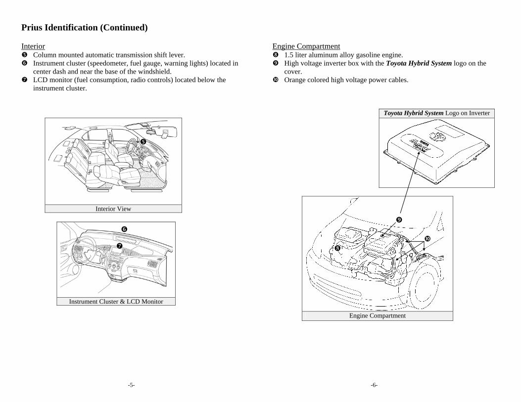
Prius Identification (Continued) Interior Column mounted automatic transmission shift lever. Instrument cluster (speedometer, fuel gauge, warning lights) located in
center dash and near the base of the windshield. LCD monitor (fuel consumption, radio controls) located below the
instrument cluster.
Interior View
Instrument Cluster & LCD Monitor
Engine Compartment 1.5 liter aluminum alloy gasoline engine. High voltage inverter box with the Toyota Hybrid System logo on the
cover. Orange colored high voltage power cables.
Toyota Hybrid System Logo on Inverter
Engine Compartment

-7- -8-
Hybrid Component Locations & Descriptions
Component Location Description
12-Volt Auxiliary Battery
Trunk, Driver Side Low voltage lead-acid battery that controls all electrical equipment except electric motor generator, and inverter.
Hybrid Vehicle (HV) Battery Pack
Trunk, Mounted to Cross Member & Behind Rear Seat
274-Volt Nickel Metal Hydride (NiMH) battery pack consisting of 38 low voltage (7.2-volt) modules connected in series.
Power Cables
Under Carriage & Engine Compartment
Orange colored power cables carry high voltage Direct Current (DC) between the HV battery pack and inverter. Also carries 3 phase Alternating Current (AC) between inverter, motor, and generator.
Inverter Engine Compartment
Converts DC electricity from HV battery pack to AC electricity that drives the electric motor. Also, converts AC from electric generator and motor (regenerative braking) to DC that recharges the HV battery pack.
Gasoline Engine
Engine Compartment
Provides two functions: 1) powers vehicle; 2) powers generator to recharge the HV battery pack. The engine is started and stopped under control of the vehicle computer.
Electric Motor
Engine Compartment
3 Phase AC permanent magnetic electric motor contained in the transaxle. Used to power the vehicle.
Electric Generator
Engine Compartment
3 Phase AC generator contained in the transaxle. Used to recharge the HV battery pack.
Fuel Tank and Fuel Lines
Undercarriage, Passenger Side
Fuel tank provides gasoline via a single fuel line to the engine. The fuel line is routed along passenger side under the floor pan.
Specifications Gasoline Engine: 70 hp, 1.5 liter Aluminum Alloy Engine Electric Motor: 44 hp, Permanent Magnet Motor Transmission: Automatic Only HV Battery: 274-Volt Sealed NiMH Curb Weight: 2,765 lbs Fuel Tank: 11.9 gals Fuel Economy: 52/45 (City/Hwy) Frame Material: Steel Unibody & Steel Body Panels
Section A-A Power Cable
12-Volt Cable Power Cables
A
A

-9- -10-
Gasoline-Electric Hybrid Vehicle Operation The vehicle starts and becomes operational by turning the ignition key to start just like any other typical automobile. However, the gasoline engine does not idle like a typical automobile and will start and stop automatically. It is important to recognize and understand the READY indicator provided in the instrument cluster. When lit, it informs the driver the vehicle is on and operational even though the gasoline engine may be off and the engine compartment is silent. Vehicle Operation With the Prius, the gasoline engine may stop and start at any time while
the READY indicator is on. Never assume the vehicle is shut off just because the engine is off.
Always look for the READY indicator status. The vehicle is shut off when the READY indicator is off.
The vehicle may be powered by:
1. The electric motor only. 2. The gasoline engine only. 3. A combination of both the electric motor and the gasoline engine.
The vehicle computer determines the mode in which the vehicle operates to improve fuel economy and reduce emissions. The driver cannot manually select the mode.
Instrument Cluster READY Indicator

-11- -12-
Hybrid Vehicle (HV) Battery Pack and Auxiliary Battery The Prius contains a high voltage, Hybrid Vehicle (HV) battery pack and a low voltage auxiliary battery. The HV battery pack contains non-spillable, sealed Nickel Metal Hydride (NiMH) battery modules and the auxiliary battery is a typical automotive lead-acid type. HV Battery Pack The HV battery pack is sealed in a metal case and is rigidly mounted to
the trunk floor pan cross member behind the rear seat. The metal case is isolated from high voltage and concealed by a fabric liner in the trunk.
The HV battery pack consists of 38 low voltage (7.2-Volt) NiMH battery
modules connected in series to produce approximately 274-Volts. Each NiMH battery module is non-spillable and sealed in a plastic case.
The electrolyte used in the NiMH battery module is an alkaline of
potassium and sodium hydroxide. The electrolyte is absorbed into the battery cell plates and will form a gel that will not normally leak, even in a collision.
In the unlikely event the battery pack is overcharged, the modules vent
gases directly outside the vehicle through a vent hose connected to each NiMH battery module.
HV Battery Pack Battery pack voltage 274-Volts Number of NiMH battery modules in the pack 38 Battery pack weight 100 lbs NiMH battery module voltage 7.2-Volts NiMH battery module dimensions (inches) 11 x 3/4 x 4 NiMH Battery module weight 2.2 lbs
Components Powered by the HV Battery Pack Electric Motor Inverter Electric Generator Power Cables HV Battery Pack Recycling The HV battery pack is recyclable. Contact the nearest Toyota dealer, or:
United States: (800) 331-4331 Canada: (888) Toyota-8
Auxiliary Battery The Prius also contains a lead-acid 12-Volt battery. This 12-Volt
auxiliary battery powers the vehicle electrical system similar to a conventional vehicle. As with other conventional vehicles, the auxiliary battery is grounded to the metal chassis of the vehicle.
The auxiliary battery is located in the trunk. It also contains a hose to
vent gases outside the vehicle if overcharged.
HV Battery Pack 12-Volt Auxiliary Battery
HV Battery Pack Case and NiMH Battery Module
NiMH Battery Module
Metal Case Top
-13- -14-
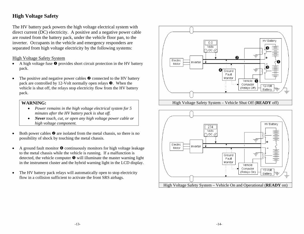
High Voltage Safety The HV battery pack powers the high voltage electrical system with direct current (DC) electricity. A positive and a negative power cable are routed from the battery pack, under the vehicle floor pan, to the inverter. Occupants in the vehicle and emergency responders are separated from high voltage electricity by the following systems: High Voltage Safety System A high voltage fuse provides short circuit protection in the HV battery
pack. The positive and negative power cables connected to the HV battery
pack are controlled by 12-Volt normally open relays . When the vehicle is shut off, the relays stop electricity flow from the HV battery pack.
WARNING:
Power remains in the high voltage electrical system for 5 minutes after the HV battery pack is shut off.
Never touch, cut, or open any high voltage power cable or high voltage component.
Both power cables are isolated from the metal chassis, so there is no
possibility of shock by touching the metal chassis. A ground fault monitor continuously monitors for high voltage leakage
to the metal chassis while the vehicle is running. If a malfunction is detected, the vehicle computer will illuminate the master warning light in the instrument cluster and the hybrid warning light in the LCD display.
The HV battery pack relays will automatically open to stop electricity
flow in a collision sufficient to activate the front SRS airbags.
High Voltage Safety System – Vehicle Shut Off (READY off)
High Voltage Safety System – Vehicle On and Operational (READY on)
-15- -16-
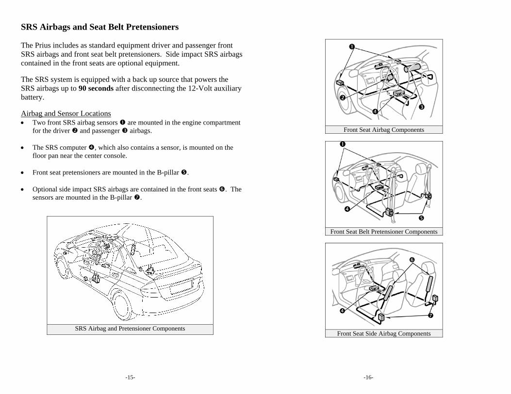
SRS Airbags and Seat Belt Pretensioners The Prius includes as standard equipment driver and passenger front SRS airbags and front seat belt pretensioners. Side impact SRS airbags contained in the front seats are optional equipment. The SRS system is equipped with a back up source that powers the SRS airbags up to 90 seconds after disconnecting the 12-Volt auxiliary battery. Airbag and Sensor Locations Two front SRS airbag sensors are mounted in the engine compartment
for the driver and passenger airbags. The SRS computer , which also contains a sensor, is mounted on the
floor pan near the center console. Front seat pretensioners are mounted in the B-pillar . Optional side impact SRS airbags are contained in the front seats . The
sensors are mounted in the B-pillar .
SRS Airbag and Pretensioner Components
Front Seat Airbag Components
Front Seat Belt Pretensioner Components
Front Seat Side Airbag Components

-17- -18-
Emergency Response On arrival, emergency responders should follow their standard operating procedures for vehicle incidents. Emergencies involving the Prius may be handled like other automobiles except as noted in these guidelines for Extrication, Fire, Overhaul, Recovery, Spills, First Aid, and Submersion. WARNING:
Never assume the Prius is shut off simply because it is silent. Always observe the instrument cluster for the READY indicator
status to verify whether the vehicle is on or shut off. Extrication Immobilize Vehicle
Chock wheels and set the parking brake. Move the shift lever to the P (park) position.
Disable Vehicle (HV battery pack, SRS airbags, & gasoline fuel pump)
Turn the ignition key off, remove the ignition key, and place on dash. Disconnect 12-Volt auxiliary battery.
-OR (if the ignition key is inaccessible)-
Disconnect the 12-Volt auxiliary battery. Remove the IGCT relay in the engine compartment as shown in the
illustration. WARNING:
After disabling the vehicle, power is maintained for 90 seconds in the SRS system and 5 minutes in the high voltage electrical system.
If either of the disabling steps above cannot be performed, proceed with caution as there is no assurance that the high voltage electrical system, SRS, or fuel pump are disabled.
Never touch, cut, or open any orange high voltage power cable or high voltage component.
Chock Wheels Set Parking Brake
Move Shift Lever To Park Remote Trunk Opener (Driver Side)
12-Volt Auxiliary Battery Cover Remote Hood Release
Hood Latch Release IGCT Relay Location
IGCT Relay

-19- -20-
Emergency Response (Continued) Extrication (Continued) Stabilize Vehicle
Crib at (4) points directly under the front and rear pillars. Do not place cribbing under the high voltage power cables, exhaust system, or fuel tank.
Access Patients
Glass Removal Use normal glass removal procedures as required.
Door Removal/Displacement
Doors can be removed by conventional rescue tools- hand, electric, and hydraulic. In certain situations, it may be easier to pry back the body to expose and unbolt the hinges.
Dash Displacement
Displace the dash by using a conventional dash roll, Modified Dash Roll, or jacking the dash.
Roof Removal
The roof may be removed as there are no SRS airbag devices above the door line.
Rescue Lift Air Bags
Responders should not place rescue lift airbags under the high voltage power cables, exhaust system, or fuel tank.
Steering and Seat Controls Tilt steering and seat controls are shown in the illustration.
Cribbing Points
Tilt Steering Control Front Seat Controls
-21- -22-
Emergency Response (Continued) Fire Approach and extinguish a fire using proper vehicle fire fighting practices as recommended by NFPA, IFSTA, or the National Fire Academy (USA). Extinguishing Agent
Water has been proven to be a suitable extinguishing agent. Initial Fire Attack
Perform a fast, aggressive fire attack. Divert the runoff from entering watershed areas. Attack teams may not be able to identify a Prius until the fire has been knocked down and overhaul operations have commenced.
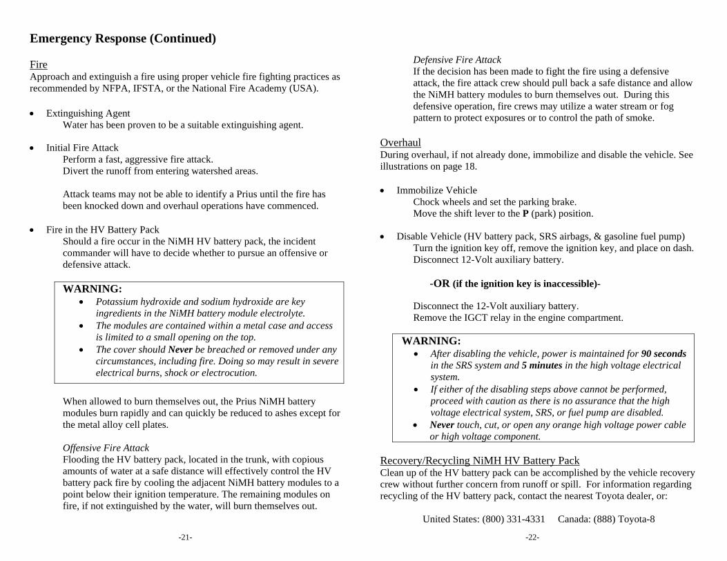
Fire in the HV Battery Pack
Should a fire occur in the NiMH HV battery pack, the incident commander will have to decide whether to pursue an offensive or defensive attack. WARNING:
Potassium hydroxide and sodium hydroxide are key ingredients in the NiMH battery module electrolyte.
The modules are contained within a metal case and access is limited to a small opening on the top.
The cover should Never be breached or removed under any circumstances, including fire. Doing so may result in severe electrical burns, shock or electrocution.
When allowed to burn themselves out, the Prius NiMH battery modules burn rapidly and can quickly be reduced to ashes except for the metal alloy cell plates.
Offensive Fire Attack Flooding the HV battery pack, located in the trunk, with copious amounts of water at a safe distance will effectively control the HV battery pack fire by cooling the adjacent NiMH battery modules to a point below their ignition temperature. The remaining modules on fire, if not extinguished by the water, will burn themselves out.
Defensive Fire Attack If the decision has been made to fight the fire using a defensive attack, the fire attack crew should pull back a safe distance and allow the NiMH battery modules to burn themselves out. During this defensive operation, fire crews may utilize a water stream or fog pattern to protect exposures or to control the path of smoke.
Overhaul During overhaul, if not already done, immobilize and disable the vehicle. See illustrations on page 18. Immobilize Vehicle
Chock wheels and set the parking brake. Move the shift lever to the P (park) position.
Disable Vehicle (HV battery pack, SRS airbags, & gasoline fuel pump)
Turn the ignition key off, remove the ignition key, and place on dash. Disconnect 12-Volt auxiliary battery.
-OR (if the ignition key is inaccessible)-
Disconnect the 12-Volt auxiliary battery. Remove the IGCT relay in the engine compartment.
WARNING:
After disabling the vehicle, power is maintained for 90 seconds in the SRS system and 5 minutes in the high voltage electrical system.
If either of the disabling steps above cannot be performed, proceed with caution as there is no assurance that the high voltage electrical system, SRS, or fuel pump are disabled.
Never touch, cut, or open any orange high voltage power cable or high voltage component.
Recovery/Recycling NiMH HV Battery Pack Clean up of the HV battery pack can be accomplished by the vehicle recovery crew without further concern from runoff or spill. For information regarding recycling of the HV battery pack, contact the nearest Toyota dealer, or:
United States: (800) 331-4331 Canada: (888) Toyota-8
-23- -24-
Emergency Response (Continued) Spills The Prius contains the same common automotive fluids used in other Toyota vehicles, with the exception of NiMH electrolyte used in HV battery pack. The NiMH battery electrolyte is a caustic alkaline (pH 13.5) that is damaging to human tissues. The electrolyte, however, is absorbed in the cell plates and will not normally spill or leak out even if a battery module is cracked. A catastrophic crash that would breach both the metal battery pack case and the plastic battery module would be a rare occurrence. Similar to using baking soda to neutralize a lead-acid battery electrolyte spill, a dilute boric acid solution or vinegar is used to neutralize a NiMH battery electrolyte spill. During an emergency, Toyota Material Safety Data Sheets (MSDS) may be requested by contacting:
United States: CHEMTREC at (800) 424-9300 Canada: CANUTEC at *666 or (613) 996-6666 (collect)
Handle NiMH Electrolyte Spills Using The Following Personal Protective
Equipment (PPE): Splash shield or safety goggles. Fold down helmet shields are not acceptable for alkaline spills. Rubber, latex or Nitrile gloves. Apron suitable for alkaline. Rubber boots.
Neutralize NiMH Electrolyte
Use a boric acid solution or vinegar. Boric acid solution - 800 grams boric acid to 20 liters water or 5.5 ounces boric acid to 1 gallon of water.
First Aid Emergency responders may not be familiar with a NiMH electrolyte exposure when rendering aid to a patient. Exposure to the electrolyte is unlikely except in a catastrophic crash or through improper handling. Utilize the following guidelines during an exposure. WARNING:
The NIMH battery electrolyte is a caustic alkaline (pH 13.5) that is damaging to human tissue.
Wear Personal Protective Equipment (PPE)
Splash shield or safety goggles. Fold down helmet shields are not acceptable for acid or alkaline spills. Rubber, latex or Nitrile gloves. Apron suitable for alkaline. Rubber boots.
Absorption
Perform gross decontamination by removing affected clothing and properly disposing of the garments. Rinse the affected areas with water for 20 minutes. Transport to the nearest emergency medical care facility.
Inhalation Non-Fire Situations
No toxic gases are emitted under normal conditions.
Inhalation Fire Situations Toxic gases are given off as the by-product of combustion. All responders in the Hot Zone should wear the proper PPE for fire fighting including SCBA. Remove patient from the hazardous environment to a safe area and administer oxygen. Transport to the nearest emergency medical care facility.
Ingestion
Do not induce vomiting. Allow patient to drink large quantities of water to dilute electrolyte (Never give water to an unconscious person). If vomiting occurs spontaneously, keep patients head lowered and forward to reduce the risk of aspiration. Transport to the nearest emergency medical care facility.
Submersion To safely handle a Prius that is fully or partially submerged in water, disable the high voltage electrical system and SRS airbags. Remove vehicle from the water. Drain water from the vehicle if possible. Follow the extrication and vehicle disabling procedure (page 17).
-25- -26-
Roadside Assistance No special or unusual handling is necessary for Prius roadside assistance. The vehicle may be handled like other Toyota vehicles and the following information may be useful for guidance. Toyota Roadside Assistance is available during the basic warranty period by contacting:
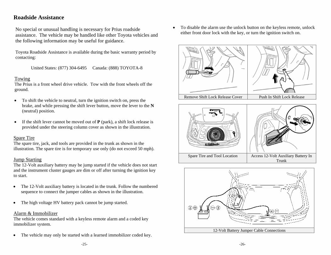
United States: (877) 304-6495 Canada: (888) TOYOTA-8 Towing The Prius is a front wheel drive vehicle. Tow with the front wheels off the ground. To shift the vehicle to neutral, turn the ignition switch on, press the
brake, and while pressing the shift lever button, move the lever to the N (neutral) position.
If the shift lever cannot be moved out of P (park), a shift lock release is
provided under the steering column cover as shown in the illustration. Spare Tire The spare tire, jack, and tools are provided in the trunk as shown in the illustration. The spare tire is for temporary use only (do not exceed 50 mph). Jump Starting The 12-Volt auxiliary battery may be jump started if the vehicle does not start and the instrument cluster gauges are dim or off after turning the ignition key to start. The 12-Volt auxiliary battery is located in the trunk. Follow the numbered
sequence to connect the jumper cables as shown in the illustration. The high voltage HV battery pack cannot be jump started. Alarm & Immobilizer The vehicle comes standard with a keyless remote alarm and a coded key immobilizer system. The vehicle may only be started with a learned immobilizer coded key.
To disable the alarm use the unlock button on the keyless remote, unlock
either front door lock with the key, or turn the ignition switch on.
Remove Shift Lock Release Cover Push In Shift Lock Release
Spare Tire and Tool Location Access 12-Volt Auxiliary Battery In
Trunk
12-Volt Battery Jumper Cable Connections

© 2001 Toyota Motor Corporation All rights reserved. This book may not be reproduced or copied, in whole or in part, without the written permission of Toyota Motor Corporation Printed in the United States of America TMS M/N 00400-ERG02-0U
Rev A (1/15/02)