00778-90013_Mar01_778D_Operating & Serv
23
778D Dual Directional Coupler Operating and Service Manual Manual part number: 00778-90013 Printed in USA March 2001 Supersedes: June 2000 Revision 2.0
-
Upload
somsak-navayon -
Category
Documents
-
view
216 -
download
0
Transcript of 00778-90013_Mar01_778D_Operating & Serv

8/10/2019 00778-90013_Mar01_778D_Operating & Serv
http://slidepdf.com/reader/full/00778-90013mar01778doperating-serv 1/23
778D Dual Directional Coupler
Operating and ServiceManual
Manual part number: 00778-90013
Printed in USA
March 2001
Supersedes: June 2000
Revision 2.0

8/10/2019 00778-90013_Mar01_778D_Operating & Serv
http://slidepdf.com/reader/full/00778-90013mar01778doperating-serv 2/23
ii Agilent 778D Operating And Service Manual
Notice
The information contained in this document is subject to change without
notice.
Agilent Technologies makes no warranty of any kind with regard to this
material, including, but not limited to, the implied warranties of
merchantability and fitness for a particular purpose. Agilent Technologies
shall not be liable for errors contained herein or for incidental or
consequential damages in connection with the furnishing, performance, or
use of this material.
Agilent Technologies assumes no responsibility for the use or reliability of
its software on equipment that is not furnished by Agilent Technologies.
This document contains proprietary information which is protected bycopyright. All rights are reserved. No part of this document may be
photocopied, reproduced, or translated to another language without prior
written consent of Agilent Technologies.
RESTRICTED RIGHTS LEGEND
Use, duplication, or disclosure by the U.S. Government is subject to
restrictions as set forth in subparagraph (c)(1)(ii) of the Rights in Technical
Data and Computer Software clause at DFARS 252.227-7013 for DOD
agencies, and subparagraphs (c)(1) and (c)(2) of the Commercial Computer
Software Restricted Rights clause at FAR 52.227-19 for other agencies.
Agilent Technologies, Inc.
1400 Fountaingrove Parkway
Santa Rosa, CA 95403-1799, U.S.A.
© Copyright 2000–2001 Agilent Technologies, Inc.

8/10/2019 00778-90013_Mar01_778D_Operating & Serv
http://slidepdf.com/reader/full/00778-90013mar01778doperating-serv 3/23
Agilent 778D Operating And Service Manual iii
What You’ll Find In This Manual…
• Overview, page 1
• Specifications, page 2
• Installation and Shipping, page 3
• Operation, page 5
• Performance Testing, page 9

8/10/2019 00778-90013_Mar01_778D_Operating & Serv
http://slidepdf.com/reader/full/00778-90013mar01778doperating-serv 4/23
iv Agilent 778D Operating And Service Manual
Warranty
Custom systems are warranted by contractual agreement between Agilent
Technologies and the customer.
Certification Agilent Technologies, Inc., certifies that this product met its published
specifications at the time of shipment from the factory. Agilent Technologies
further certifies that its calibration measurements are traceable to the
United States National Institute of Standards and Technology (NIST,
formerly NBS), to the extent allowed by the Institute’s calibration facility,
and to the calibration facilities of other International Standards
Organization members.
Warranty This Agilent Technologies system product is warranted against defects in
materials and workmanship for a period corresponding to the individual
warranty periods of its component products. Instruments are warranted for a
period of one year. During the warranty period, Agilent Technologies will, at
its option, either repair or replace products that prove to be defective.
Warranty service for products installed by Agilent Technologies and certain
other products designated by Agilent Technologies will be performed at
Buyer’s facility at no charge within Agilent Technologies service travel
areas. Outside Agilent Technologies service travel areas, warranty service
will be performed at Buyer’s facility only upon Agilent Technologies’ prior
agreement and Buyer shall pay Agilent Technologies’ round trip travel
expenses. In all other areas, products must be returned to a service facility
designated by Agilent Technologies.
For products returned to Agilent Technologies for warranty service, Buyer
shall prepay shipping charges to Agilent Technologies and Agilent
Technologies shall pay shipping charges to return the product to Buyer.
However, Buyer shall pay all shipping charges, duties, and taxes for products
returned to Agilent Technologies from another country.
Agilent Technologies warrants that its software and firmware designated by
Agilent Technologies for use with an instrument will execute its
programming instructions when properly installed on that instrument.
Agilent Technologies does not warrant that the operation of the instrument,
or software, or firmware will be uninterrupted or error free.
LIMITATION OF WARRANTY. The foregoing warranty shall not apply
to defects resulting from improper or inadequate maintenance by Buyer,
Buyer-supplied software or interfacing, unauthorized modification or
misuse, operation outside of the environmental specifications for the
product, or improper site preparation or maintenance.
8/10/2019 00778-90013_Mar01_778D_Operating & Serv
http://slidepdf.com/reader/full/00778-90013mar01778doperating-serv 5/23
Agilent 778D Operating And Service Manual v
NO OTHER WARRANTY IS EXPRESSED OR IMPLIED. AGILENT
TECHNOLOGIES SPECIFICALLY DISCLAIMS THE IMPLIED
WARRANTIES OR MERCHANTABILITY AND FITNESS FOR A
PARTICULAR PURPOSE.
EXCLUSIVE REMEDIES. THE REMEDIES PROVIDED HEREIN ARE
BUYER’S SOLE AND EXCLUSIVE REMEDIES. AGILENTTECHNOLOGIES SHALL NOT BE LIABLE FOR ANY DIRECT,
INDIRECT, SPECIAL, INCIDENTAL, OR CONSEQUENTIAL
DAMAGES, WHETHER BASED ON CONTRACT, TORT, OR ANY
OTHER LEGAL THEORY.
YEAR 2000. Agilent Technologies warrants that each Agilent Technologies
hardware, software, and firmware product on Agilent Technologies’
Corporate Price List (dated July 1, 1998 or later) delivered under the
product’s contract of sale will be able to accurately process date data
(including, but not limited to, calculating, comparing, and sequencing) from,
into, and between the twentieth and twenty-first centuries, and the years
1999 and 2000, including leap year calculations, when used in accordance
with the product documentation provided that all other products (that is,
hardware, software, firmware) used in combination with such Agilent
Technologies product(s) properly exchange date data with it. If the
agreement requires that specific Agilent Technologies products must
perform as a system in accordance with the foregoing warranty, then that
warranty will apply to those Agilent Technologies products as a system, and
Customer retains sole responsibility to ensure the year 2000 readiness of its
information technology and business environment. The duration of this
warranty extends through January 31, 2001.
The remedies available under this warranty will be defined in, and subject to,the terms and limitations of the warranties contained in the contract of sale.
To the extent permitted by local law, this warranty applies only to branded
Agilent Technologies products and not to products manufacture by others
that may be sold or distributed by Agilent Technologies. Nothing in this
warranty will be construed to limit any rights or remedies provided
elsewhere in the contract of sale with respect to matters other than year 2000
compliance.
Assistance Product maintenance agreements and other customer assistance agreements
are available for Agilent Technologies products.
For assistance, call your local Agilent Technologies Sales and Service Office
(refer to “Service and Support” on page vi).

8/10/2019 00778-90013_Mar01_778D_Operating & Serv
http://slidepdf.com/reader/full/00778-90013mar01778doperating-serv 6/23
vi Agilent 778D Operating And Service Manual
Service and Support
By internet, phone, or fax, get assistance with all your test and measurement
needs.
Online assistance: www.agilent.com/find/assist
United States
(tel) 1 800 452 4844
J apan
(tel) (+ 81) 426 56 7832
(fax ) (+ 81) 426 56 7840
New Zealand
(tel) 0 800 738 378
(fax ) (+ 64) 4 495 8950
Europe
(tel) (+ 31) 20 547 2323
(fax) (+ 31) 20 547
2390
Canada
(tel) 1 877 894 4414
(fa x) (905) 282 6495
Latin America
(tel) (305) 269 7500
(fax ) (305) 269 7599
Australia
(tel) 1 800 629 485
(fax ) (+ 61) 3 9210
5947
Asia Call Center Numbers
Country Phone Number Fax Number
S inga pore 1-800-375-8100 (65) 836-0252
Ma la ysia 1-800-828-848 1-800-801664
P hilippines (632) 8426802
1-800-16510170 (P LD T
Subscriber Only)
(632) 8426809
1-800-16510288 (P LD T
Subscriber Only)
Tha ila nd (088) 226-008 (out side B angkok)
(662) 661-3999 (wit hin B a ngk ok)
(66) 1-661-3714
H ong Kong 800-930-871 (852) 2506 9233
Ta iw a n 0800-047-866 (886) 2 25456723
P eople’s Repu blic of
China
800-810-0189 (prefer red )
10800-650-0021
10800-650-0121
India 1-600-11-2929 000-800-650-1101

8/10/2019 00778-90013_Mar01_778D_Operating & Serv
http://slidepdf.com/reader/full/00778-90013mar01778doperating-serv 7/23
Agilent 778D Operating And Service Manual vii
Safety and Regulatory Information
Review this product and related documentation to familiarize yourself with
safety markings and instructions before you operate the instrument. This
product has been designed and tested in accordance with international
standards.
WARNING The WARNING notice denotes a hazard. It calls attention to a procedure,
practice, or the like, that, if not correctly performed or adhered to, could result
in personal injury. Do not proceed beyond a WARNING notice until the
indicated conditions are fully understood and met.
CAUTION The CAUTION notice denotes a hazard. It calls attention to an operating
procedure, practice, or the like, which, if not correctly performed or adhered
to, could result in damage to the product or loss of important data. Do not
proceed beyond a CAUTION notice until the indicated conditions are fully
understood and met.
Instrument Markings
When you see this symbol on your instrument, you should refer to the instrument’s
instruction manual for important information.
This symbol indicates hazardous voltages.
The laser radiation symbol is marked on products that have a laser output.
This symbol indicates that the instrument requires alternating current (ac) input.
The CE mark is a registered trademark of the European Community. If it is
accompanied by a year, it indicates the year the design was proven.
The CSA mark is a registered trademark of the Canadian Standards Association.
1SM1-A This text indicates that the instrument is an Industrial Scientific and Medical Group 1
Class A product (CISPER 11, Clause 4).
This symbol indicates that the power line switch is ON.
This symbol indicates that the power line switch is OFF or in STANDBY position.
!

8/10/2019 00778-90013_Mar01_778D_Operating & Serv
http://slidepdf.com/reader/full/00778-90013mar01778doperating-serv 8/23
viii Agilent 778D Operating And Service Manual
Safety Earth
Ground
This is a Safety Class I product (provided with a protective earthing
terminal). An uninterruptible safety earth ground must be provided from the
main power source to the product input wiring terminals, power cord, or
supplied power cord set. Whenever it is likely that the protection has been
impaired, the product must be made inoperative and secured against any
unintended operation.
Before Applying Power Verify that the product is configured to match the available main power
source as described in the input power configuration instructions in this
manual. If this product is to be powered by autotransformer, make sure the
common terminal is connected to the neutral (grounded) side of the ac power
supply.

8/10/2019 00778-90013_Mar01_778D_Operating & Serv
http://slidepdf.com/reader/full/00778-90013mar01778doperating-serv 9/23
Agilent 778D Operating and Service Manual 1
Overview
This coaxial dual directional coupler has a frequency range extending over
four octaves from 100 MHz to 2 GHz. Although the coupling factor
increases 6 dB/octave below 100 MHz, directivity remains above 36 dB.
Thus, the coupler can be used below 100 MHz as well as above. The
usefulness below 100 MHz is restricted only by the amount of signal source
power and/or the sensitivity of the RF detector connected to the coupler.
The unidirectional characteristic of the Agilent 778D dual directional
coupler makes it an important tool in microwave measurement systems. The
778D has the property of inducing, in an auxiliary line, a contra-directional
flow of power which is proportional to the power flowing in the main guide.
This coupler may be used in the measurement of reflection coefficients or
SWR over a very wide frequency range. The relatively constant couplingacross several frequency bands and the stability of coupling with time make
the 778D useful, also, as a wideband attenuator or for power monitoring
applications.
Description To achieve its broad frequency coverage, the 778D’s directivity is optimized
for mainline energy flowing in one direction. This means that there is a
preferred orientation for the 778D. To achieve the measurement accuracies
in the specifications, the test device or system should be connected where the
778D is labeled TEST PORT. To accommodate test devices with Type N or
APC-7 connectors, a choice of connectors is available on the TEST PORT
(see Options outlined in “Specifications” on page 2).
With the APC-7 precision sexless connector on the output, the coupler can
be conveniently converted to other types of connectors by the use of an
adapter. Adapters are available to the SMA (OSM), TNC, GR900, and
others, so that the coupler becomes a versatile device for making
measurements on many different types of connectors. The Amphenol APC-7
is a sexless connector with very low SWR. This precision connector makes
possible the construction of adapters with low SWR.
8/10/2019 00778-90013_Mar01_778D_Operating & Serv
http://slidepdf.com/reader/full/00778-90013mar01778doperating-serv 10/23
2 Agilent 778D Operating and Service Manual
Specifications
Specifications
Specifications for the 778D are shown in the following table.
Characteristic Value
Frequency range 100 to 2000 MHz (usable below 100 MHz)
Directivity
Auxiliary arm 0.1 to 1.0 GHz
Auxiliary arm 1.0 to 2.0 GHz
See figure on page 1
A 36 dB
B 30 dB
A 32 dB
B 30 dB
Coupling Attenuation nominal coupling above 450 MHz is 20 dB
nominal coupling above 450 MHz is 20 dB increasing with a
slope of 0.006 dB/MHz for decreasing frequency.
Coupling variation ±1.5 dB from nominal
Cyclical variation Frequency is similar to Figure 7 on page 10.1
1. See Figure 6 on page 8 for a typical coupling curve.
Tracking Auxiliary outputs typically track within 0.7 dB.
Phase tracking typically 4°.
SWR Primary Line ≤1.1
Auxiliary Arms ≤1.1
Maximum main line power 50 W average
500 W peak
Accessories available adapters 2
2. Adapters from APC-7 to TNC, GR-900, GR-874 as well as the above are available from Amphenol
RF Division, Danbury, CN)
11533A APC-7 to SMA male
11534A APC-7 to SMA female
11525A APC-7 to Type N male
11524A APC-7 to Type N female
Connectors Choice of main line connectors (see options)
Auxiliary Arms have Type N female
All Type N connectors stainless steel, compatible with
MIL-C-39012 and MIL-C-71.
Dimension 16-3/4 in long x 4-3/8 in high x 1-3/16 in wide
(425 mm x 111 mm x 30 mm)
Net weight 3-3/4 lb (1.5 kg)
Options available 778D (Type N female output, Type N male input connectors)
Option 011 (APC-7 output, Type N female input connectors)Option 012 (Type N male output, Type N female input
connectors)
8/10/2019 00778-90013_Mar01_778D_Operating & Serv
http://slidepdf.com/reader/full/00778-90013mar01778doperating-serv 11/23
Agilent 778D Operating and Service Manual 3
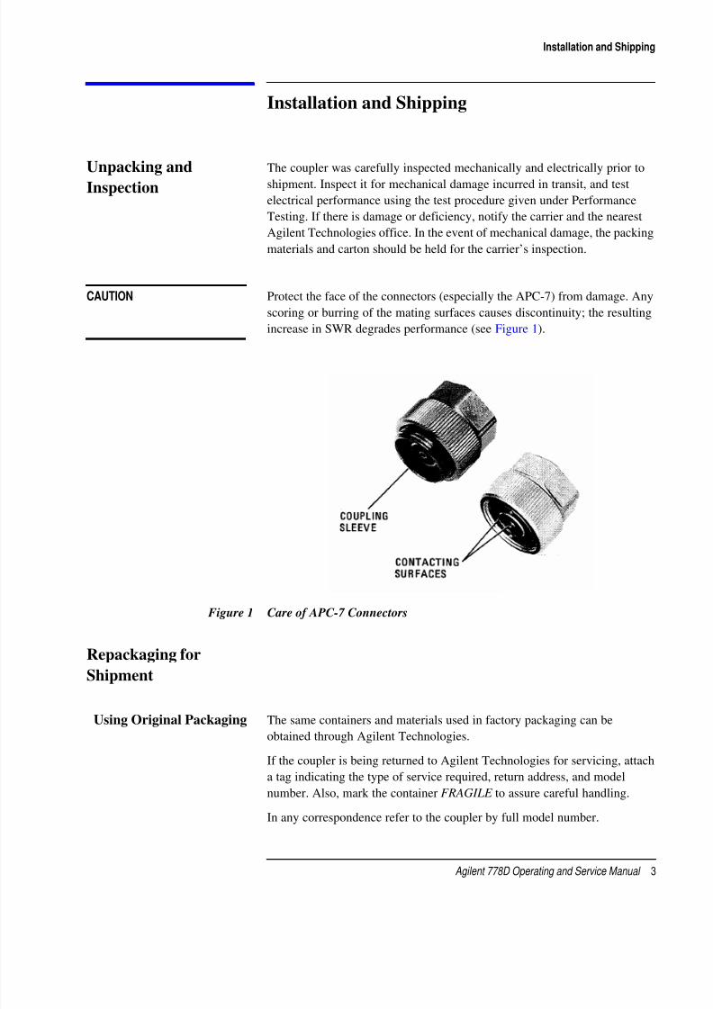
Installation and Shipping
Installation and Shipping
Unpacking and
Inspection
The coupler was carefully inspected mechanically and electrically prior to
shipment. Inspect it for mechanical damage incurred in transit, and test
electrical performance using the test procedure given under Performance
Testing. If there is damage or deficiency, notify the carrier and the nearest
Agilent Technologies office. In the event of mechanical damage, the packing
materials and carton should be held for the carrier’s inspection.
CAUTION Protect the face of the connectors (especially the APC-7) from damage. Any
scoring or burring of the mating surfaces causes discontinuity; the resulting
increase in SWR degrades performance (see Figure 1).
Figure 1 Care of APC-7 Connectors
Repackaging for
Shipment
Using Original Packaging The same containers and materials used in factory packaging can be
obtained through Agilent Technologies.
If the coupler is being returned to Agilent Technologies for servicing, attach
a tag indicating the type of service required, return address, and model
number. Also, mark the container FRAGILE to assure careful handling.
In any correspondence refer to the coupler by full model number.

8/10/2019 00778-90013_Mar01_778D_Operating & Serv
http://slidepdf.com/reader/full/00778-90013mar01778doperating-serv 12/23
4 Agilent 778D Operating and Service Manual
Installation and Shipping
Using Other Packaging The following general instructions should be used for repackaging with
commercially available materials:
1. Wrap the coupler in heavy paper or plastic. (If shipping to a Agilent
Technologies office or service center, attach a tag indicating the type of
service required, return address, and model number.)
2. Use a strong shipping container. A double wall carton made of 2.4 MPa
(350 psi) test material is adequate.
3. Use enough shock-absorbing material (3-4-inch layer) around all sides
of the coupler to provide firm cushion and prevent movement inside the
container.
4. Seal the shipping container securely.
5. Mark the shipping container FRAGILE to assure careful handling.
Load-Bearing When installing be sure auxiliary equipment supports its own weight. Thecoupler, particularly the connectors, is not designed to carry weight. Load
limits for APC-7 connectors are given in Figure 2.
Figure 2 Load Limits for APC-7 Connector

8/10/2019 00778-90013_Mar01_778D_Operating & Serv
http://slidepdf.com/reader/full/00778-90013mar01778doperating-serv 13/23
Agilent 778D Operating and Service Manual 5
Operation
Operation
Signal Flow Unlike some other dual-directional couplers, this coupler is polarized. For
best performance the signal must flow through the coupler as shown in
Figure 3. Observe the TEST PORT designation on the label. DO NOT
reverse the coupler since the directivity may be somewhat lower in the
reverse direction. To test devices with other types of connectors, another
coupler with the correct mating test port connector is recommended. Using
an adapter will degrade the effective directivity of the measurement.
Figure 3 Signal Flow
Coupler Temperature Operate the coupler at normal room temperature and do not temperature
cycle the coupler in use or storage. Heat cycling may degrade the
performance of the coupler.
Reflectometer
Measurements
Figure 4 on page 6 shows an arrangement in which swept-frequency
measurements of reflection coefficient are easily made with the coupler.
Incident and reflected signals are detected from the auxiliary arms of the
coupler. The signals can then be displayed on an oscilloscope or X-Y
recorder to give a visual display of reflection coefficient or SWR.
8/10/2019 00778-90013_Mar01_778D_Operating & Serv
http://slidepdf.com/reader/full/00778-90013mar01778doperating-serv 14/23
6 Agilent 778D Operating and Service Manual
Operation
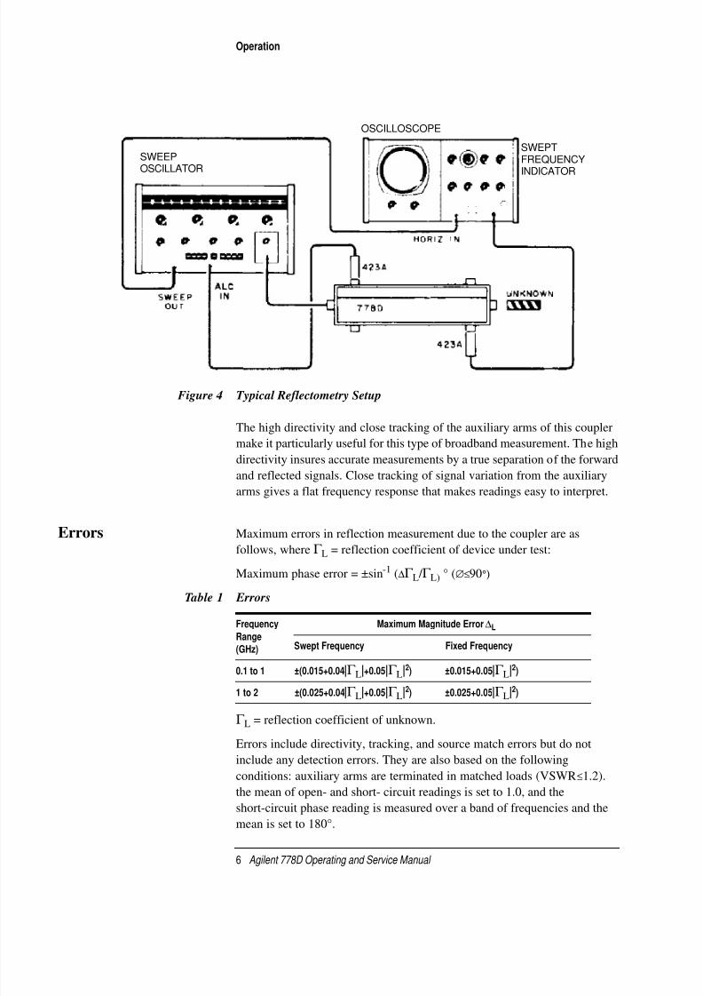
Figure 4 Typical Reflectometry Setup
The high directivity and close tracking of the auxiliary arms of this coupler
make it particularly useful for this type of broadband measurement. The high
directivity insures accurate measurements by a true separation of the forward
and reflected signals. Close tracking of signal variation from the auxiliary
arms gives a flat frequency response that makes readings easy to interpret.
Errors Maximum errors in reflection measurement due to the coupler are as
follows, where Γ L = reflection coefficient of device under test:
Maximum phase error = ±sin-1 (∆Γ L / Γ L) ° (∅≤90°)
Γ L = reflection coefficient of unknown.
Errors include directivity, tracking, and source match errors but do not
include any detection errors. They are also based on the following
conditions: auxiliary arms are terminated in matched loads (VSWR≤1.2).
the mean of open- and short- circuit readings is set to 1.0, and the
short-circuit phase reading is measured over a band of frequencies and the
mean is set to 180°.
SWEEP
OSCILLATOR
OSCILLOSCOPE
SWEPT
FREQUENCY
INDICATOR
Table 1 Errors
Frequency
Range
(GHz)
Maximum Magnitude Error ∆L
Swept Frequency Fixed Frequency
0.1 to 1 ±(0.015+0.04|Γ L|+0.05|Γ L|2) ±0.015+0.05|Γ L|2)
1 to 2 ±(0.025+0.04|Γ L|+0.05|Γ L|2
) ±0.025+0.05|Γ L|2
)

8/10/2019 00778-90013_Mar01_778D_Operating & Serv
http://slidepdf.com/reader/full/00778-90013mar01778doperating-serv 15/23
Agilent 778D Operating and Service Manual 7
Operation
Impedance
Measurement
The 778D is also well suited for measurements of impedance when used
with the Agilent 8508A vector voltmeter (see Figure 5). Again, a
reflectometry technique is used. With the vector voltmeter, however, both
magnitude and phase of the reflection coefficient can be measured.
Figure 5 Setup for Impedance Measurement
Data can be read from the two meters of the vector voltmeter and transferred
directly to a Smith Chart to provide impedance information of such devices
as antennas or other passive components. In addition, with an appropriate
bias supply, active components, such as transistors, can also be quickly
measured and their characteristics determined with this setup. The 778D is
well suited for these types of measurements since both the phase and
magnitude variation between the coupling arms have been closely controlled
in the design of the coupler.
Power Leveling The 778D has cyclic coupling variations of up to ±2 dB. For this reason it is
not recommended for power leveling that requires flatness exceeding these
tolerances. A typical coupling curve is shown in Figure 7 on page 10.
Maintenance The directional coupler should need very little maintenance besides keeping
it clean and protecting the connector faces.
909A
909A
50-Ohm
“T”
50-Ohm
“T”

8/10/2019 00778-90013_Mar01_778D_Operating & Serv
http://slidepdf.com/reader/full/00778-90013mar01778doperating-serv 16/23
8 Agilent 778D Operating and Service Manual
Operation
Figure 6 Typical Coupling Variation with Frequency

8/10/2019 00778-90013_Mar01_778D_Operating & Serv
http://slidepdf.com/reader/full/00778-90013mar01778doperating-serv 17/23
Agilent 778D Operating and Service Manual 9
Performance Testing
Performance Testing
Use the following procedure for initial inspection, performance testing, or
whenever the coupler performance is suspected. Table 2 lists equipment
necessary for testing. Other equipment may be substituted provided its
specifications equal or exceed the specifications listed under Critical
Specifications. The coupler should be tested on a swept-frequency basis to
assure that there are no out-of-specification narrow-frequency bands
between the spot frequencies tested on a fixed-frequency basis. If the results
of swept-frequency testing are doubtful or if the equipment for
swept-frequency testing is not available, the fixed-frequency test may be
used. Table 3 on page 11 provides a place to record the results.
Table 2 Recommended Test Equipment
Instrument Critical Specifications
Sweep oscillator Frequency: 0.1 to 2.0 GHz
Modulation: 1kHz square wave
Leveling: —V proportional to RF
Low-pass filter Rejects: second harmonics lowest frequency
Rejection: ≥50 dB at 1.25 fco
Network analyzer No other network analyzer is recommended
SWR meter Frequency: compatible with sweep oscillator
Accuracy: ±0.1 dB
X-Y recorder Impedance: 200 K ohms/V
Sensitivity: ≥50 mV/in
Crystal detector (2) Frequency: 0.1 to 2.0 GHz
Sensitivity: >4.0 mV / µW
Coaxial attenuator Frequency: 0.1 to 2.0 GHz
Attenuation: 20 dB or 10 dB
Low reflection termination SWR: ≤1.005 0.1 MHz to 2.0 GHz
Type N connectors
Oscilloscope Vertical Sensitivity: >10 mV/cm
Horizontal Sweep: synchronized ext
Termination (2) Frequency: band of interest
Load SWR: <1.01, de to 2 GHz
Dual directional coupler Frequency: band of interest
Directivity: >40 dB
Impedance: 50 ohms coaxial
Short 7 mm coaxial Type N

8/10/2019 00778-90013_Mar01_778D_Operating & Serv
http://slidepdf.com/reader/full/00778-90013mar01778doperating-serv 18/23
10 Agilent 778D Operating and Service Manual
Performance Testing
Figure 7 Typical Coupling Variation with Frequency
Adapter (2) Type N male to male
1 kHz Filter Adapter Rejects 1 kHz and above
Table 2 Recommended Test Equipment (Continued)
Instrument Critical Specifications

8/10/2019 00778-90013_Mar01_778D_Operating & Serv
http://slidepdf.com/reader/full/00778-90013mar01778doperating-serv 19/23
Agilent 778D Operating and Service Manual 11
Performance Testing
Swept-Frequency
Directivity
Directivity (in dB) is equal to:
where
P = Power
aux = auxiliary armmain = main arm
NOTE The power input to the main arm is the same for both measurements.
To measure the directivity proceed as follows:
1. Connect the equipment as shown in Figure 8 on page 12 (the purpose of
the 1 kHz low-pass filter input to the oscilloscope is to reduce noise).
Table 3 Performance Test Record
Tested by:
Date:
Dual-Directional Coupler:
Instrument Serial Number:
Directivity:
Auxiliary Arm: 0.1 to 1.0 GHz 1.0 to 2.0 GHz
A _________dB (≤ —36dB) _________dB (≤ —32dB)
B _________dB (≤ —30dB) _________dB (≤ —30dB)
SWR Measurement
Primary Line ___________ (≤1.1) ___________ (≤1.1)
Auxiliary Arm ___________ (≤1.1) ___________ (≤1.1)
10′Paux( )when Pmain flows forward
Paux( )when Pmain flows reversed------------------------------------------------------------------------------------log

8/10/2019 00778-90013_Mar01_778D_Operating & Serv
http://slidepdf.com/reader/full/00778-90013mar01778doperating-serv 20/23

8/10/2019 00778-90013_Mar01_778D_Operating & Serv
http://slidepdf.com/reader/full/00778-90013mar01778doperating-serv 21/23
Agilent 778D Operating and Service Manual 13
Performance Testing
3. To establish a reference remove the low reflection termination. This
open will give a condition of 100% reflection. If a good short is available
use also and take the amplitude reference as the average between the
shorted and open conditions.
4. Be sure network analyzer is phase locked over entire range. The display
on the oscilloscope should be an unbroken line. If not, adjust network
analyzer SWEEP STABILITY and/or AMPLITUDE controls to phaselock over the entire sweep.
5. Zero network analyzer phase gain meter on 10 dB AMPLITUDE range
with AMPL VERNIER control or AMPLITUDE TEST CHANNEL
GAIN (dB).
6. Draw a horizontal line with a grease pencil on the CRT somewhere
above the middle X-axis line.
7. Place the average of the reference trace on the grease pencil line by
adjusting the oscilloscope VERTICAL POSITION control.
8. Put the low reflection termination back on the coupler as shown inFigure 8.
9. Increase the network analyzer TEST CHANNEL GAIN (DB) by the
amount of the directivity specification for this frequency range.
10. The entire trace should stay below the grease pencil line. If a portion of
the trace goes above the line the coupler may or may not be out of
specification (the reflection from the load may be adding to the
directivity of the coupler). Test these ambiguous frequencies with the
fixed frequency testing following.
11. Repeat this test at the other frequency range given in the
“Specifications” on page 2. Then turn the coupler around to test the
directivity at port B and repeat the above tests.
Vertical Sens 50 mV, calibration to make 1 dB gain change on
network analyzer equal 1 cm vertical change on CRT
Horizon Sens 1 V/cm
Sweep Mode Ext
Input DC
Table 4 Control Settings (Continued)
Characteristic Setting

8/10/2019 00778-90013_Mar01_778D_Operating & Serv
http://slidepdf.com/reader/full/00778-90013mar01778doperating-serv 22/23
14 Agilent 778D Operating and Service Manual
Performance Testing
Termination In the preceding of the following tests use the best termination obtainable.
The accuracy of the tests will depend to a great extent upon the quality of the
termination. Note that the quality of the termination includes any adapter
necessary for connection. The adapter reflection coefficient will add
vectorially to the termination reflection coefficient. These instructions
assume the use of a termination with a total SWR of 1.005 or less.
SWR Measurement SWR in this procedure will be measured in terms of reflection coefficient.
Because the directional couplers used in this procedure have finite
directivity, the measurement error due to directivity is taken into
consideration in determining the test limits.
1. Connect the equipment as shown in Figure 9.
Figure 9 SWR Measurement Setup
2. Set controls as shown in Table 4 on page 12.
3. Set sweep oscillator to sweep an octave band in the range 0.1 to 2 GHz
with no modulation.
4. To establish a reference, remove the termination. This open will give a
condition of 100% reflection. If a good short is available, use it also and

8/10/2019 00778-90013_Mar01_778D_Operating & Serv
http://slidepdf.com/reader/full/00778-90013mar01778doperating-serv 23/23
Performance Testing
take the amplitude reference as the average between the shorted and
open conditions.
5. Be sure network analyzer is phase locked over entire range. The display
on the polar display should be an unbroken circle. If not, adjust network
analyzer SWEEP STABILITY and/or AMPLITUDE controls to phase
lock over the entire sweep.
6. Push and hold the polar display’s BEAM CTR push button and adjust
HORIZ POS and VERT POS controls to place the dot in the center of
the graticule. To bring the dot onto the display, rotate each positioning
control about five turns counterclockwise or until a slight increase in
resistance to movement is encountered.Then turn each control two and
one-half turns clockwise.
7. Center the trace on the outer graticule circle, using the network analyzer
position and amplitude controls. If a good short is available, average the
position between the open and shorted indications. Note TEST
CHANNEL GAIN reading.
8. Increase TEST CHANNEL GAIN by 26 dB. The outer graticule is now
calibrated to a reflection coefficient of 0.05 and the inner graticule to
0.01.
9. Connect the mainline of the 778D under test in place of the termination
shown in Figure 9. Terminate the mainline of the 778D under test with
the best termination available. A poorer termination may be used to
terminate the auxiliary arms.
10. The indication should be less than the following limits:
0.1 to 1.0 GHz:0.0321.0 to 2.0 GHz: 0.022
11. If these limits are exceeded at any frequency, set the sweep oscillator for
CW operation at this frequency.
12. Remove the 778D under test from the reflectometer and connect a
low-reflection termination to the reflectometer.
13. With the VERT and HORIZ Position controls set the dot to the center of
the graticule. This effectively cancels out the directivity signal at this
frequency.
14. Remove the low-reflection termination and reconnect the 778D under
test. The indication should be less than 0.045 (0.1 to 2.0 GHz).


![Global Serv[0]](https://static.fdocuments.in/doc/165x107/55cf8c7f5503462b138d09a0/global-serv0.jpg)