0 Massachusetts DG Collaborative Thursday, Feb 9th DG Interconnection Standards Francis Cummings,...
22
1 Massachusetts DG Collaborative http://www.masstech.org/polic y/dgcollab Thursday, Feb 9th DG Interconnection Standards Francis Cummings, Massachusetts Technology Collaborative
-
Upload
amanda-ward -
Category
Documents
-
view
215 -
download
0
Transcript of 0 Massachusetts DG Collaborative Thursday, Feb 9th DG Interconnection Standards Francis Cummings,...
1
Massachusetts DG Collaborative
http://www.masstech.org/policy/dgcollab
Thursday, Feb 9th DG Interconnection Standards
Francis Cummings,Massachusetts Technology Collaborative
[email protected] (978-985-1557)
2
Massachusetts DG Collaborative
• Proceeding: D.T.E. 02-38, Massachusetts Department of Telecommunications And Energy (DTE), began in 2002
• Topics assigned to DG Collaborative: 1. Uniform Interconnection Tariff:
3/03 -- Collaborative Report, followed by proposed tariff
» Facilitated by Raab Associates 4/04 -- DTE-approved tariffs became effective 5/05 -- Small changes filed in 2005 Annual Report 6/06 -- Final changes due to DTE
2. Role of DG in Distribution Company Planning
3
Uniform Interconnection Tariff – 2005 Annual Report
• May 31, 2005 -- submitted to the Massachusetts DTE – see: http://www.masstech.org/renewableenergy/public_policy/DG/2005_annualreport.htm
• December 27, 2005 -- DTE issued Order 02-38-C – see: http://www.masstech.org/renewableenergy/public_policy/DG/resources/02-38-C_DTE-order.pdf
Approved the "Revised Model Interconnection Standard Tariff" with the changes to the Interconnection process proposed in the Collaborative's May 2005 Report, except for the indemnification language opposed by DCAM -- see: http://www.masstech.org/renewableenergy/public_policy/DG/resources/02-38-C_Att-A_Tariff.doc
4
Uniform Interconnection Tariff – 2006 Final Report
• Final Report is due June 2006• Goals:
— Improve effectiveness and efficiency of interconnection process
» File any proposed final changes to Interconnection Tariff
— Identify any changes to interconnection for networks, or other next steps on remaining technical issues:
» Current tariff limits interconnection on networks» Network interconnection has become a separate,
controversial issue, with its own “Technical Working Group”
• MTC engaging a mediator for the final negotiations (“Phase 4”)
• New parties interested in DG in Massachusetts welcome to join now— Next 3 meeting dates: 2/15, 3/15, 4/26
5
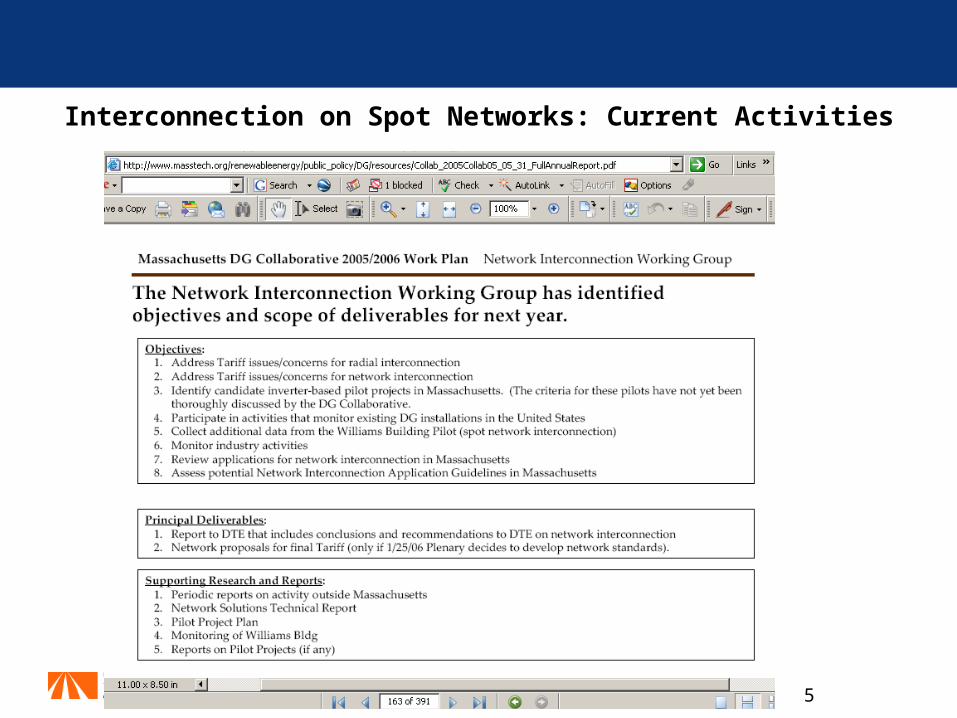
Interconnection on Spot Networks: Current Activities
6
Test Results on Boston Spot Network Interconnection at Williams Building: Presentation by W. E. Feero, P.E., December 16, 2005
• The MTC, the Massachusetts DG Collaborative and the US General Services Administration held a workshop for W.E. Feero to present the results of his analysis of detailed data on the performance of the DG systems interconnected to the NSTAR downtown network at the GSA's Williams Building.
• The findings of a two year monitoring study of the protection performance for the Distributed Generation, DG, installations at the Williams Building was presented. The generation consisted of a 28 kW photovoltaic system and a 75 kW induction generator. The study also included a simulation of the spot network system, the induction generator, and the photovoltaic system's interfacing inverter using the commercially available PSCAD electromagnetic transients program. The simulation allowed the findings of the study to be extended to larger generation installations and to all three generation types: induction, synchronous, and inverter interfaced.
7
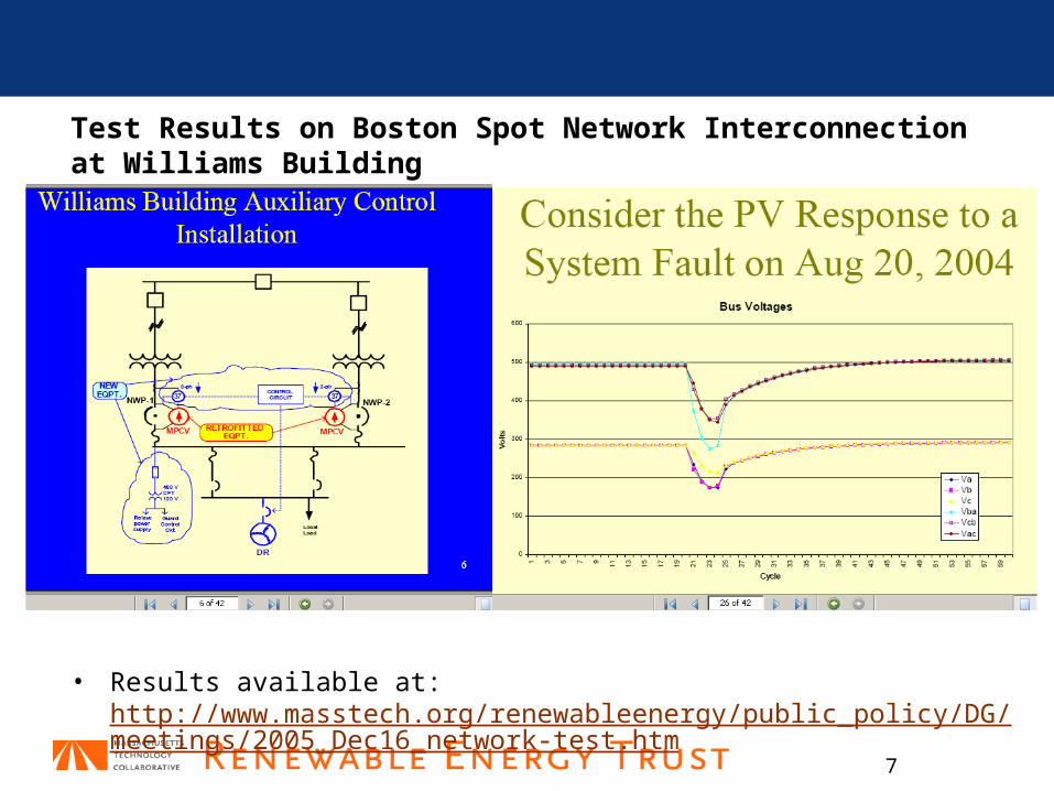
Test Results on Boston Spot Network Interconnection at Williams Building
• Results available at: http://www.masstech.org/renewableenergy/public_policy/DG/meetings/2005_Dec16_network-test.htm
8
Role of DG in Distribution Company Planning
• Distribution Planning Working Group • Coordination with other projects (MTC Pilots,
EPRI):— MTC Congestion Relief Pilots— EPRI DER Public/Private Partnership
Nine Potential Components of a Win-Win Framework
• Economic Analysis by Navigant Consulting (excerpts below)
• 3 Technical Challenges• Future Activities
9
MTC Congestion Relief Pilots
• Partnership:— Renewable Energy Trust of the MTC— National Grid & other interested distribution companies
• DE Installations:— renewable DG and other distributed energy resources
demand-response & energy efficiency, storage & other distributed resources
— collect data on all benefits and costs from such DE (T&D, markets)
• Win/Win Strategies (benefits to both distribution system and host customers)— Enhanced “Smart DE” – joint optimization in design and
dispatch— Modes of Operation— Business Models – and potentially rate recommendations
10
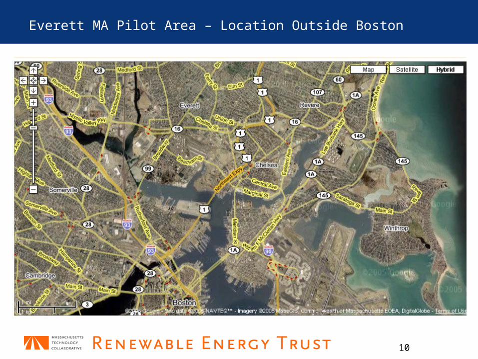
Everett MA Pilot Area – Location Outside Boston
11
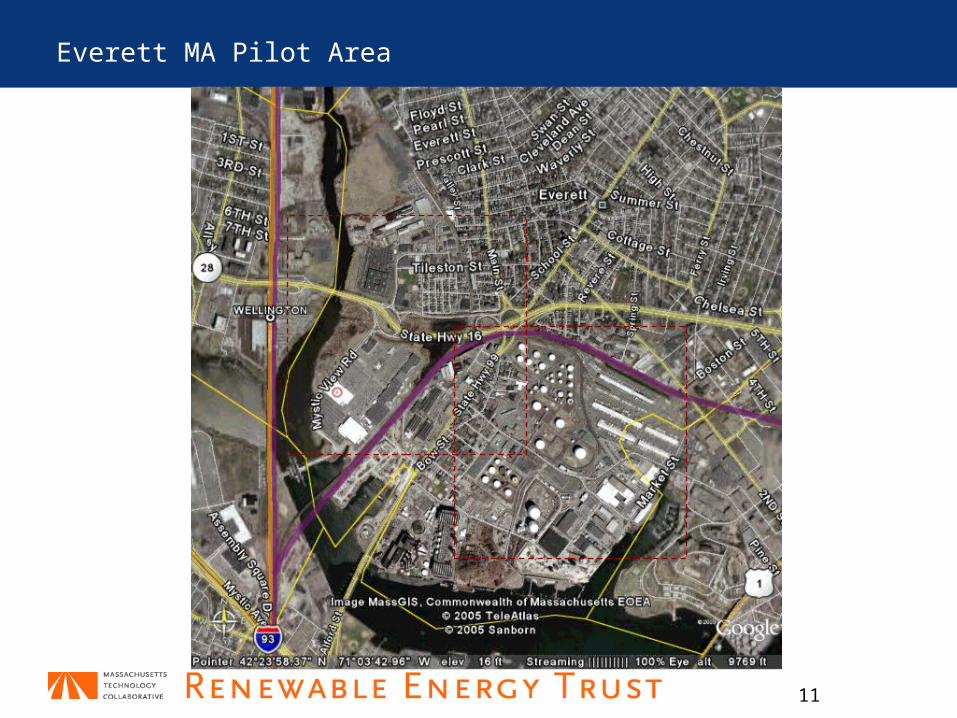
Everett MA Pilot Area

12
EPRI DER Public/Private Partnership
• Phase 2 of multi-state project: 2006 - 2007• Goal: create incentives for electricity providers to
proactively integrate DER.• For further information:
— see the proposal entitled “Creating and Demonstrating Incentives for Electricity Providers to Integrate Distributed Energy Resources (DER),” recently submitted by Massachusetts DOER to the State Technologies Advancement Collaborative (STAC), posted at:http://www.masstech.org/renewableenergy/public_policy/DG/resources/DistributionPlanning_Win-Win_Resources.htm
— contact EPRI or DOER for information on participation.• Pilot projects in CA and MA, including:
— Congestion Relief Pilot: MTC and National Grid (see below)
13
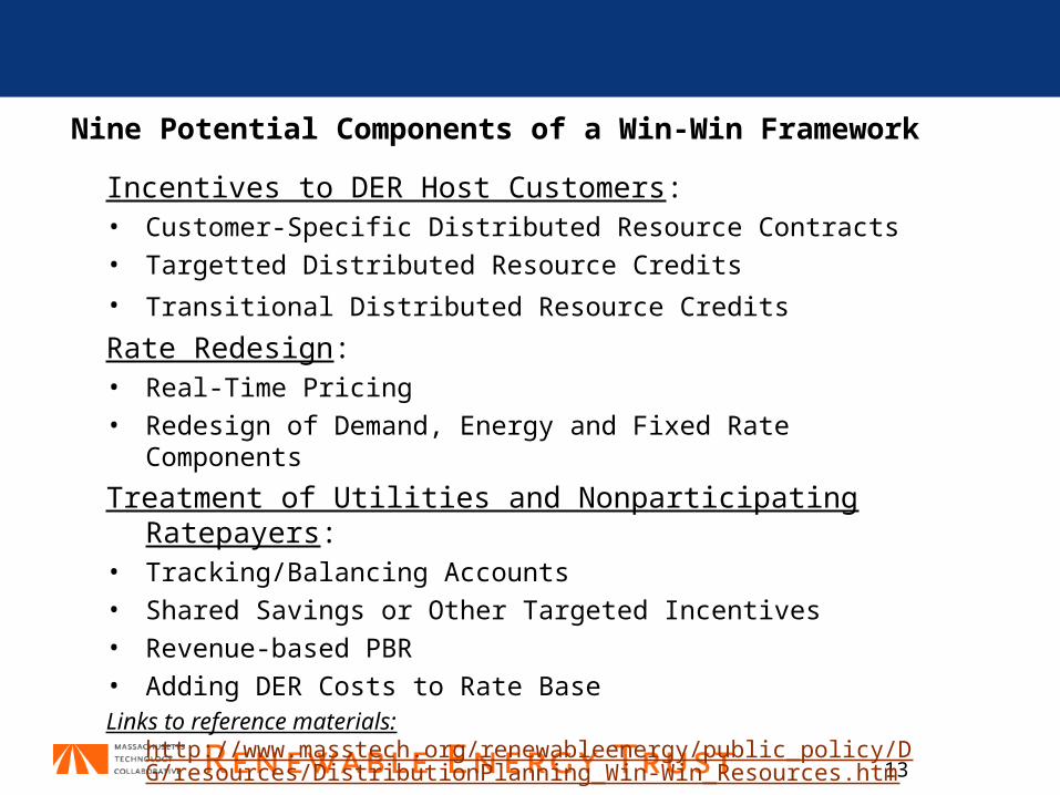
Nine Potential Components of a Win-Win Framework
Incentives to DER Host Customers:• Customer-Specific Distributed Resource Contracts • Targetted Distributed Resource Credits
• Transitional Distributed Resource Credits Rate Redesign:• Real-Time Pricing • Redesign of Demand, Energy and Fixed Rate
Components
Treatment of Utilities and Nonparticipating Ratepayers:
• Tracking/Balancing Accounts • Shared Savings or Other Targeted Incentives • Revenue-based PBR • Adding DER Costs to Rate Base Links to reference materials:
http://www.masstech.org/renewableenergy/public_policy/DG/resources/DistributionPlanning_Win-Win_Resources.htm
Distributed Generation andDistribution Planning:
An Economic Analysis for the Massachusetts DG Collaborative
January 20, 2006
Prepared by Navigant Consulting, Inc. under contract to the
Massachusetts Technology Collaborative
posted at:
Attachment B (accompanying the January 31, 2006 letter to Massachusetts DTE and the January 2006 Interim Report on DG and Distribution Deferral by the Distribution Planning Work Group)
15
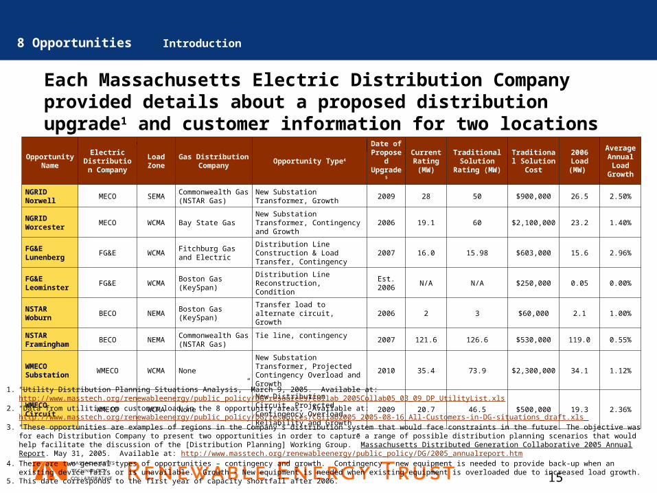
Each Massachusetts Electric Distribution Company provided details about a proposed distribution upgrade1 and customer information for two locations within their distribution system.2, 3
Opportunity Name
Electric Distribution
Company
Load Zone
Gas Distribution Company
Opportunity Type4
Date of Propos
ed Upgrad
e5
Current Rating (MW)
Traditional Solution
Rating (MW)
Traditional Solution
Cost
2006 Load
(MW)
Average Annual Load
Growth
NGRID Norwell
MECO SEMACommonwealth Gas (NSTAR Gas)
New Substation Transformer, Growth
2009 28 50 $900,000 26.5 2.50%
NGRID Worcester
MECO WCMA Bay State GasNew Substation Transformer, Contingency and Growth
2006 19.1 60 $2,100,000 23.2 1.40%
FG&E Lunenberg
FG&E WCMAFitchburg Gas and Electric
Distribution Line Construction & Load Transfer, Contingency
2007 16.0 15.98 $603,000 15.6 2.96%
FG&E Leominster
FG&E WCMABoston Gas (KeySpan)
Distribution Line Reconstruction, Condition
Est. 2006
N/A N/A $250,000 0.05 0.00%
NSTAR Woburn
BECO NEMABoston Gas (KeySpan)
Transfer load to alternate circuit, Growth
2006 2 3 $60,000 2.1 1.00%
NSTAR Framingham
BECO NEMACommonwealth Gas (NSTAR Gas)
Tie line, contingency2007 121.6 126.6 $530,000 119.0 0.55%
WMECO Substation
WMECO WCMA None
New Substation Transformer, Projected Contingency Overload and Growth
2010 35.4 73.9 $2,300,000 34.1 1.12%
WMECO Circuit
WMECO WCMA None
New Distribution Circuit, Projected Contingency Overload, Reliability and Growth
2009 20.7 46.5 $500,000 19.3 2.36%1. “Utility Distribution Planning Situations Analysis,” March 9, 2005. Available at:
http://www.masstech.org/renewableenergy/public_policy/DG/resources/Collab_2005Collab05_03_09_DP_UtilityList.xls2. “Data from utilities on customer load in the 8 opportunity areas,” Available at:
http://www.masstech.org/renewableenergy/public_policy/DG/resources/Collab2005_2005-08-16_All-Customers-in-DG-situations_draft.xls 3. “These opportunities are examples of regions in the Company’s distribution system that would face constraints in the future. The objective was for each Distribution
Company to present two opportunities in order to capture a range of possible distribution planning scenarios that would help facilitate the discussion of the [Distribution Planning] Working Group.” Massachusetts Distributed Generation Collaborative 2005 Annual Report. May 31, 2005. Available at: http://www.masstech.org/renewableenergy/public_policy/DG/2005_annualreport.htm
4. There are two general types of opportunities – contingency and growth. Contingency - new equipment is needed to provide back-up when an existing device fails or is unavailable. Growth - New equipment is needed when existing equipment is overloaded due to increased load growth.
5. This date corresponds to the first year of capacity shortfall after 2006.
8 Opportunities Introduction

16
For each opportunity, NCI repeats the 3-step process to determine when and how much DG must be installed to defer the proposed T&D upgrade.
T&D Deferral Module
DG Cost Module
Reliability Module
1 2 3
Opportunity Data Include:•Cost of T&D Solution•Proposed Year of Upgrade
Economic Assumptions•Inflation rate, 3% per year•Cost of Capital, ~8% (varies by utility)•Depreciation set at current rates based on 2004 FERC Form 1 data
Module Inputs:•DG attributes: type, size, and availability •Opportunity load profile (developed by aggregating customer load data for the specific opportunity)•Annual peak load data (provided by the distribution companies)•Annual DG additions
•The Reliability Module outputs the Peak Load Availability
Revenue Requirements Approach Incorporates•Deferred Capacity•Operating Savings•Debt and Return on Equity•Operating Costs
DG Assumptions:•Electric Output (kW) and Efficiency (%)•Equipment and Installation Costs•DG units are diesel generators with selective catalytic reduction (SCR)•Utility owns the DG (a leasing option is also analyzed)•Utility receives capacity and energy credits for the DG it installs
Revenue Requirements Approach Incorporates•Deferred Capacity•Operating Savings•Debt and Return on Equity
Iterative process
On an annual basis the cost of the DG solution is compared to the deferral savings. When the annual cost of the DG solution is greater than the annual savings of the T&D deferral, the deferral period ends.
8 Opportunities Active Utility Approach
Economic Assumptions:•Inflation rate, 3% per year•Cost of Capital, ~8% (varies by utility)•Depreciation set at current rates based on 2004 FERC Form 1 data
An iterative process is employed to meet the Peak Load Availability threshold of 0.999 by changing the type, size and timing of DG additions.

17
For every customer, or group of customers, Navigant repeats a three step process to determine the aggregate annual DG potential for an opportunity.
Status Quo Model
2T&D
Deferral Module
1
Reliability Module
3
Energy Cost Savings Module:•Incorporate a one-time incentive payment based on opportunity and length of deferral (reduces payback period)
•Include DR with a 2 yr simple paybackMarket Penetration Module:•Same assumptions as compared to the Status Quo scenario.
Market Adoption Module:•There is a more rapid adoption (as compared to the Status Quo scenario) of DG, EE and DR through market transformation efforts.
•Customers now adopt DG within 5 years•Customers now adopt EE within 2 years•Customers now adopt DR within 2 years
•Calculate a one-time incentive payment for installing DG, EE or committing to a DR program.•Determine NPV of the deferral savings over the deferral period; divide by the capacity shortfall multiplied by 1.5.•This factor (1.5) is intended to cover the reliability needs.
8 Opportunities Active Customer Approach
0%
20%
40%
60%
80%
100%
0 2 4 6 8 10Simple Payback (yrs)
Cum
ula
tive
Mar
ket
Pen
etra
tion
(%)
Module Inputs:•DER attributes: type, size, and availability •Opportunity load profile (developed by aggregating customer load data for the specific opportunity)•Annual peak load data (provided by the distribution companies)•Annual DER additions
•The Reliability Module outputs the Peak Load Availability
Opportunity Data Include:•Cost of T&D Solution•Proposed Year of Upgrade
Economic Assumptions•Inflation rate, 3% per year•Cost of Capital, ~8% (varies by utility)•Depreciation set at current rates based on 2004 FERC Form 1 data
Revenue Requirements Approach Incorporates•Deferred Capacity•Operating Savings•Debt and Return on Equity
18
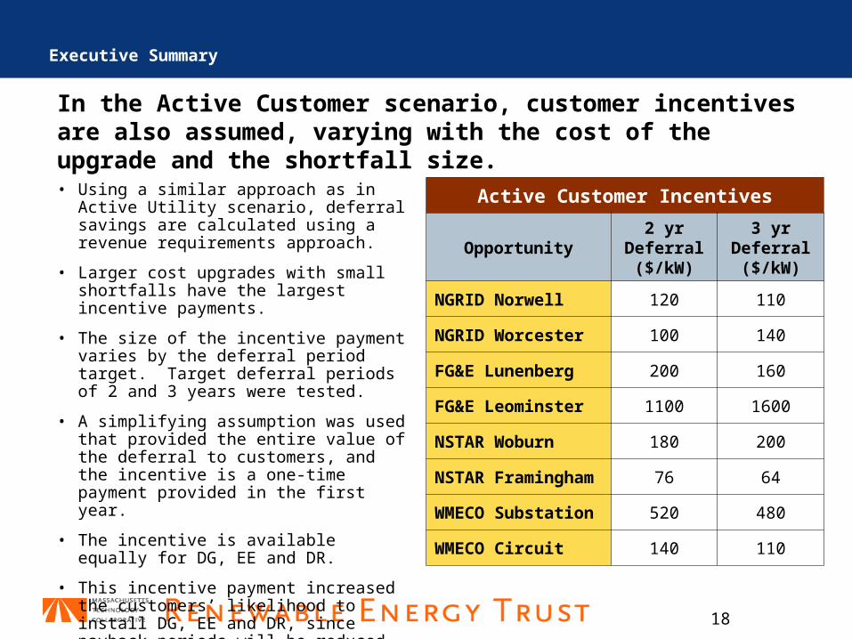
In the Active Customer scenario, customer incentives are also assumed, varying with the cost of the upgrade and the shortfall size.
Active Customer Incentives
Opportunity2 yr
Deferral ($/kW)
3 yr Deferral ($/kW)
NGRID Norwell 120 110
NGRID Worcester 100 140
FG&E Lunenberg 200 160
FG&E Leominster 1100 1600
NSTAR Woburn 180 200
NSTAR Framingham
76 64
WMECO Substation
520 480
WMECO Circuit 140 110
• Using a similar approach as in Active Utility scenario, deferral savings are calculated using a revenue requirements approach.
• Larger cost upgrades with small shortfalls have the largest incentive payments.
• The size of the incentive payment varies by the deferral period target. Target deferral periods of 2 and 3 years were tested.
• A simplifying assumption was used that provided the entire value of the deferral to customers, and the incentive is a one-time payment provided in the first year.
• The incentive is available equally for DG, EE and DR.
• This incentive payment increased the customers’ likelihood to install DG, EE and DR, since payback periods will be reduced.
Executive Summary
19
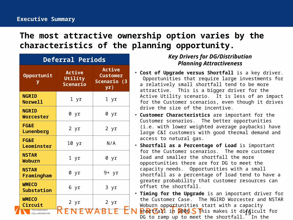
The most attractive ownership option varies by the characteristics of the planning opportunity.
Deferral Periods
Opportunity
Active Utility
Scenario
Active Customer
Scenario (3 yr)
NGRID Norwell
1 yr 1 yr
NGRID Worcester
0 yr 0 yr
FG&E Lunenberg
2 yr 2 yr
FG&E Leominster
10 yr N/A
NSTAR Woburn
1 yr 0 yr
NSTAR Framingham
0 yr 9+ yr
WMECO Substation
6 yr 3 yr
WMECO Circuit
2 yr 2 yr
Executive Summary
Key Drivers for DG/DistributionPlanning Attractiveness
• Cost of Upgrade versus Shortfall is a key driver. Opportunities that require large investments for a relatively small shortfall tend to be more attractive. This is a bigger driver for the Active Utility scenario. It is less of an impact for the Customer scenarios, even though it drives drive the size of the incentive.
• Customer Characteristics are important for the Customer scenarios. The better opportunities (i.e. with lower weighted average paybacks) have large C&I customers with good thermal demand and access to natural gas.
• Shortfall as a Percentage of Load is important for the Customer scenarios. The more customer load and smaller the shortfall the more opportunities there are for DG to meet the capacity needs. Opportunities with a small shortfall as a percentage of load tend to have a greater probability that customer resources can offset the shortfall.
• Timing for the Upgrade is an important driver for the Customer Case. The NGIRD Worcester and NSTAR Woburn opportunities start with a capacity shortfall in 2006. This makes it difficult for DG to ramp up to meet the shortfall. In the Active Utility scenario, DG may be installed more quickly.
• Load Growth is an important driver for both cases. Opportunities with slower load growth tend to be more attractive.
20
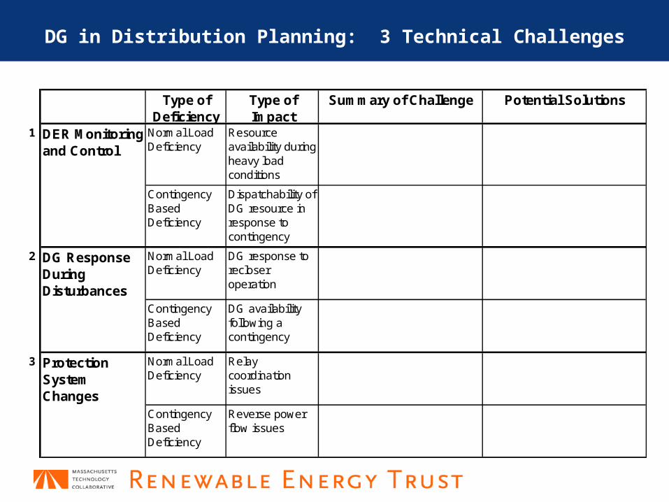
DG in Distribution Planning: 3 Technical Challenges
Type of Deficiency
Type of Impact
Summary of Challenge Potential Solutions
1 DER Monitoring and Control
Normal Load Deficiency
Resource availability during heavy load conditions
Contingency Based Deficiency
Dispatchability of DG resource in response to contingency
2 DG Response During Disturbances
Normal Load Deficiency
DG response to recloser operation
Contingency Based Deficiency
DG availability following a contingency
3 Protection System Changes
Normal Load Deficiency
Relay coordination issues
Contingency Based Deficiency
Reverse power flow issues
21
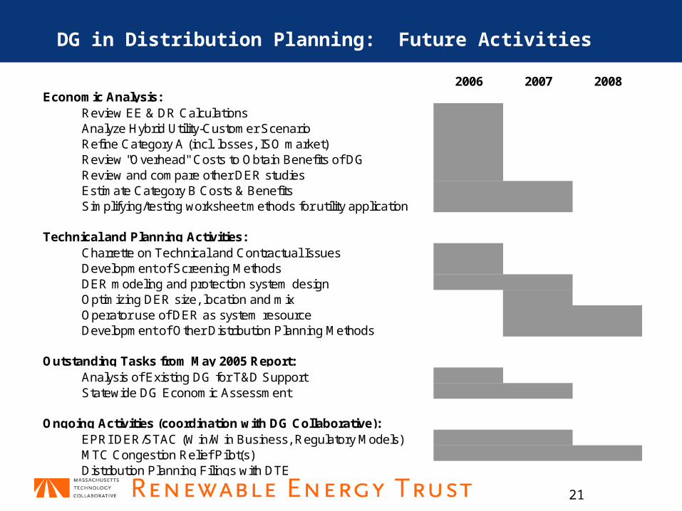
DG in Distribution Planning: Future Activities
2006 2007 2008Economic Analysis:
Review EE & DR CalculationsAnalyze Hybrid Utility-Customer ScenarioRefine Category A (incl. losses, ISO market)Review "Overhead" Costs to Obtain Benefits of DGReview and compare other DER studiesEstimate Category B Costs & BenefitsSimplifying/testing worksheet methods for utility application
Technical and Planning Activities:Charrette on Technical and Contractual IssuesDevelopment of Screening MethodsDER modeling and protection system designOptimizing DER size, location and mixOperator use of DER as system resourceDevelopment of Other Distribution Planning Methods
Outstanding Tasks from May 2005 Report:Analysis of Existing DG for T&D SupportStatewide DG Economic Assessment
Ongoing Activities (coordination with DG Collaborative):EPRI DER/STAC (Win/Win Business, Regulatory Models)MTC Congestion Relief Pilot(s)Distribution Planning Filings with DTE
22
Discussion
• For further information, contact:Francis Cummings, Massachusetts Technology [email protected] (cell)