0 Load Calculation Manual 2003.04.03 Output : 1. Screen Outputs (Results, Pareto Chart, Hourly...
21
1 Load Calculation Manual 2003.04.03 Output : 1. Screen Outputs (Results, Pareto Chart, Hourly Estimation) 2. Optional Outputs (*CLTD.txt, *TETD.txt) 3. Reports (*.txt `)
-
Upload
bernice-ford -
Category
Documents
-
view
223 -
download
3
Transcript of 0 Load Calculation Manual 2003.04.03 Output : 1. Screen Outputs (Results, Pareto Chart, Hourly...

1
Load Calculation Manual
2003.04.03
Output : 1. Screen Outputs (Results, Pareto Chart, Hourly Estimation)
2. Optional Outputs (*CLTD.txt, *TETD.txt)
3. Reports (*.txt `)
2
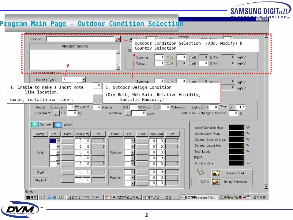
Outdoor Condition Selection (Add, Modify) & Country Selection
1. Outdoor Design Condition
(Dry Bulb, Web Bulb, Relative Humidity, Specific Humidity)
1. Enable to make a short note like location,
owner, installation time..
Program Main Page – Outdoor Condition Selection

3
1. Indoor Design Conditions (DB, WB, RH, SH)
2. Summer, Winter Design Conditions are necessary.
1. Building Type (Single Story, Top Story, Multi…)
2. This input condition is used in CLTD/SCL Method
1. If select “Room Name”, then internal DB
displays the most recommendable data for internal heat
2. Want to modify this data, you can change the
values of *.MST file by using ACCESS software
3. Or rewrite the data of heat arousal in the box manually
Program Main Page – Indoor Condition Selection
4
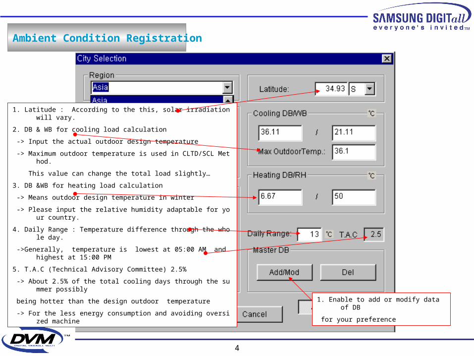
Ambient Condition Registration
1. Latitude : According to the this, solar irradiation will vary.
2. DB & WB for cooling load calculation
-> Input the actual outdoor design temperature
-> Maximum outdoor temperature is used in CLTD/SCL Method.
This value can change the total load slightly…
3. DB &WB for heating load calculation
-> Means outdoor design temperature in winter
-> Please input the relative humidity adaptable for your country.
4. Daily Range : Temperature difference through the whole day.
->Generally, temperature is lowest at 05:00 AM and highest at 15:00 PM
5. T.A.C (Technical Advisory Committee) 2.5%
-> About 2.5% of the total cooling days through the summer possibly
being hotter than the design outdoor temperature
-> For the less energy consumption and avoiding oversized machine
1. Enable to add or modify data of DB
for your preference
5
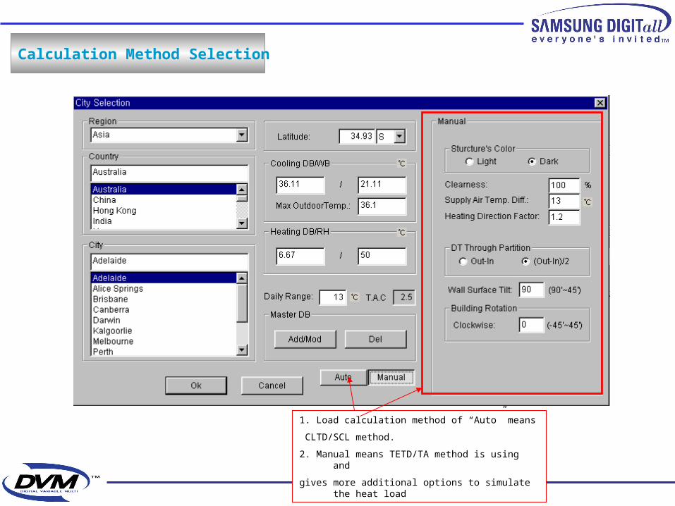
Calculation Method Selection
1. Load calculation method of “Auto” means
CLTD/SCL method.
2. Manual means TETD/TA method is using and
gives more additional options to simulate the heat load

6
1. Ventilation Method1. Existing Equipment Selection
1. Heat Reclaim Efficiency
1. Ballast Factor for Lights
1. Heating Load Calculation
1. Cooling Load Calculation
Internal Condition Input
7
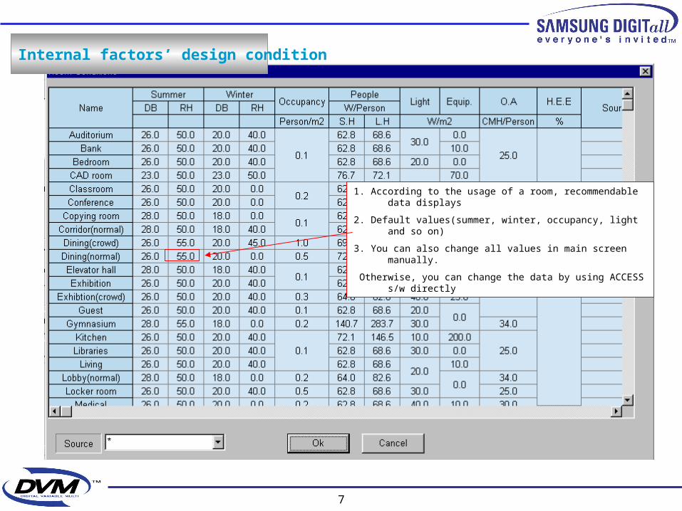
Internal factors’ design condition
1. According to the usage of a room, recommendable data displays
2. Default values(summer, winter, occupancy, light and so on)
3. You can also change all values in main screen manually.
Otherwise, you can change the data by using ACCESS s/w directly
8
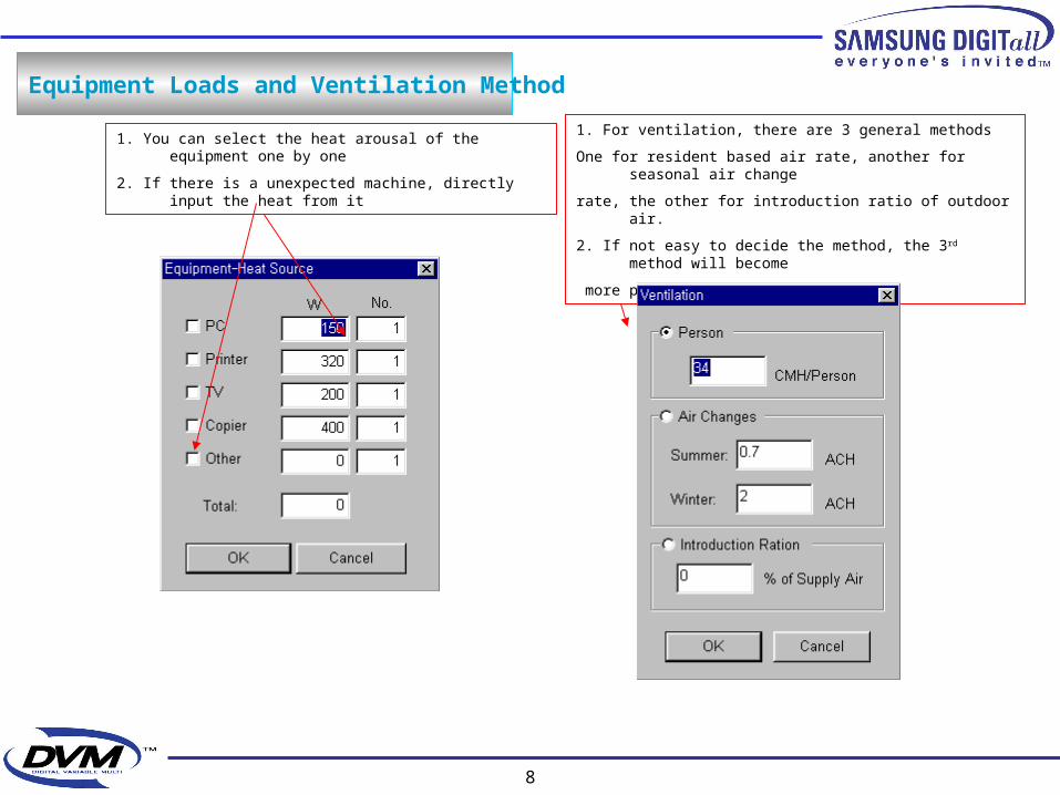
Equipment Loads and Ventilation Method
1. You can select the heat arousal of the equipment one by one
2. If there is a unexpected machine, directly input the heat from it
1. For ventilation, there are 3 general methods
One for resident based air rate, another for seasonal air change
rate, the other for introduction ratio of outdoor air.
2. If not easy to decide the method, the 3rd method will become
more practical application
9
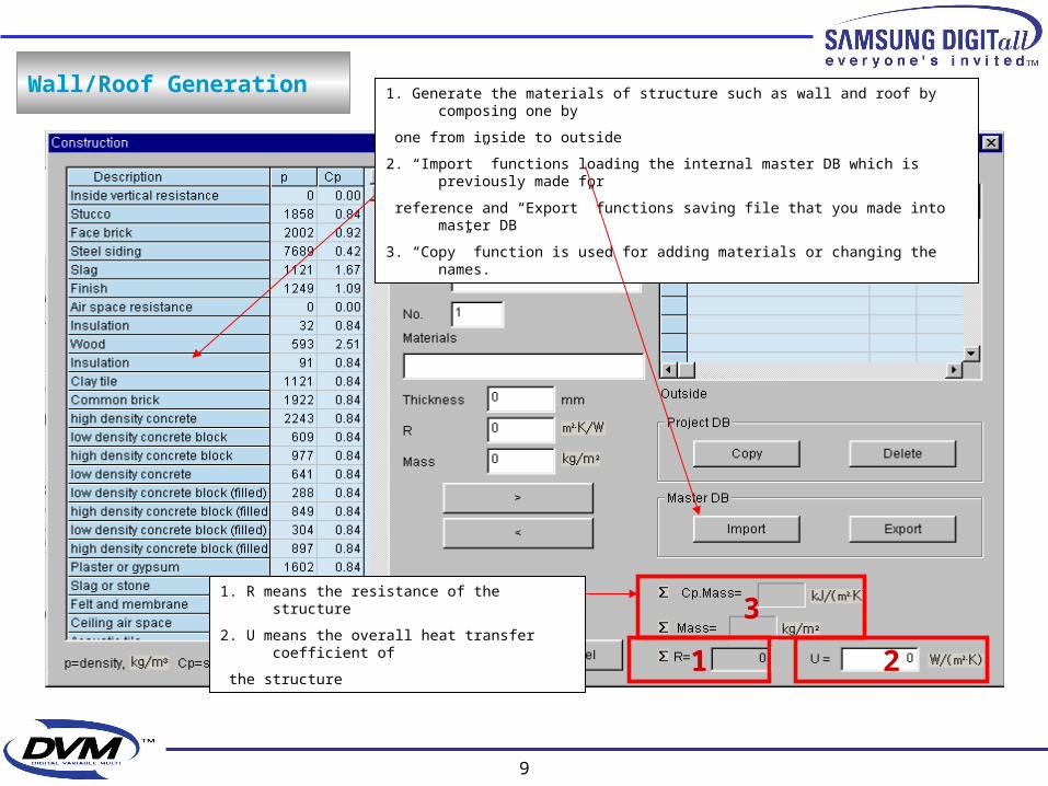
Wall/Roof Generation 1. Generate the materials of structure such as wall and roof by composing one by
one from inside to outside
2. “Import” functions loading the internal master DB which is previously made for
reference and “Export” functions saving file that you made into master DB
3. “Copy” function is used for adding materials or changing the names.
1 2
31. R means the resistance of the structure
2. U means the overall heat transfer coefficient of
the structure
10
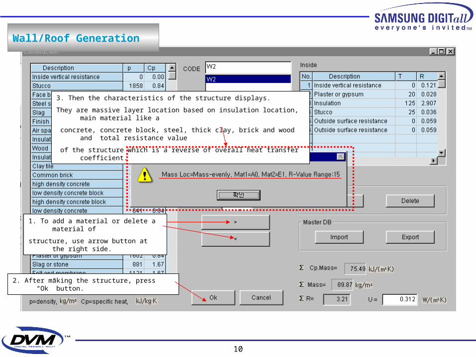
1. To add a material or delete a material of
structure, use arrow button at the right side.
2. After making the structure, press “Ok” button.
3. Then the characteristics of the structure displays.
They are massive layer location based on insulation location, main material like a
concrete, concrete block, steel, thick clay, brick and wood and total resistance value
of the structure which is a reverse of overall heat transfer coefficient.
Wall/Roof Generation

11
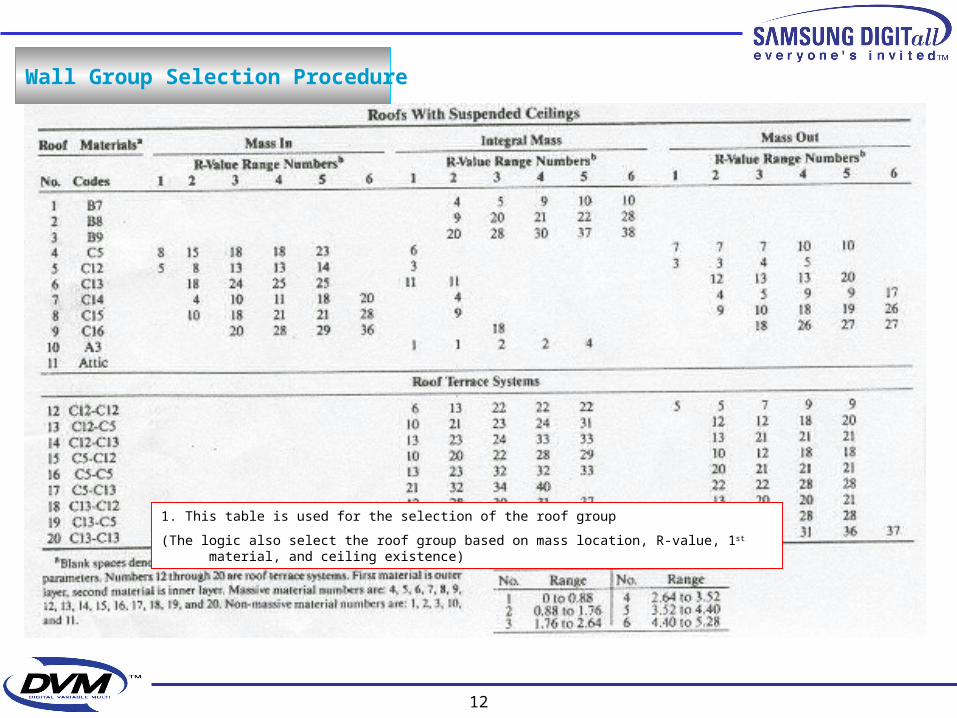
Wall Group Selection Procedure
1. All walls and roofs can be classified on 41, 42 types respectively. If the intentionally made
structure doesn’t exist in DB, then the logic of program automatically select a certain group which is
the most similar in DB physically. Being similar of structure physically means the structure has
the same range of mass and heat capacity
2. TETD/TA method and CLTD/SCL method use the same DB(data base) of structure.
1. Based on the resistance value, main material, 2nd material, wall group
number can be decided and each wall group has its own temperature
variation during the day in DB
12
Wall Group Selection Procedure
1. This table is used for the selection of the roof group
(The logic also select the roof group based on mass location, R-value, 1st material, and ceiling existence)

13
Structure Group Configuration
1. Each wall and roof group has its own time lag and decrement factor of heat flux
2. Every material of a structure has a alphabetic symbol which has its own property (density, mass per unit area)
In the next page, alphabetic symbol will come with description.

14
1. The description of the material
Material in Structure
15
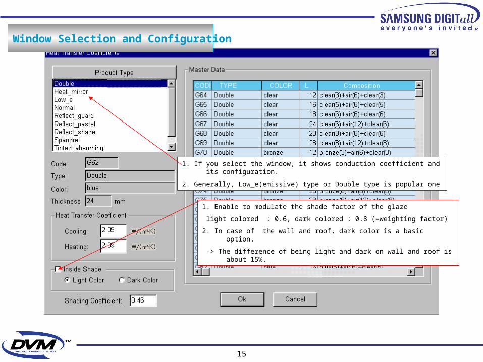
Window Selection and Configuration
1. Enable to modulate the shade factor of the glaze
light colored : 0.6, dark colored : 0.8 (=weighting factor)
2. In case of the wall and roof, dark color is a basic option.
-> The difference of being light and dark on wall and roof is about 15%.
1. If you select the window, it shows conduction coefficient and its configuration.
2. Generally, Low_e(emissive) type or Double type is popular one
16
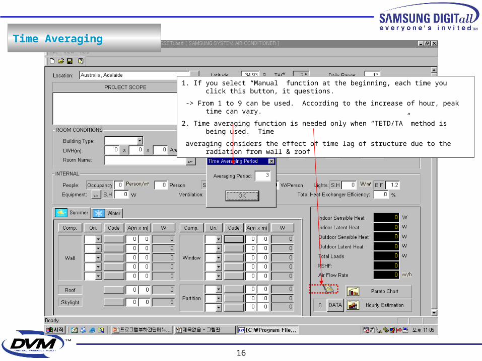
Time Averaging
1. If you select “Manual” function at the beginning, each time you click this button, it questions.
-> From 1 to 9 can be used. According to the increase of hour, peak time can vary.
2. Time averaging function is needed only when “TETD/TA” method is being used. Time
averaging considers the effect of time lag of structure due to the radiation from wall & roof
17
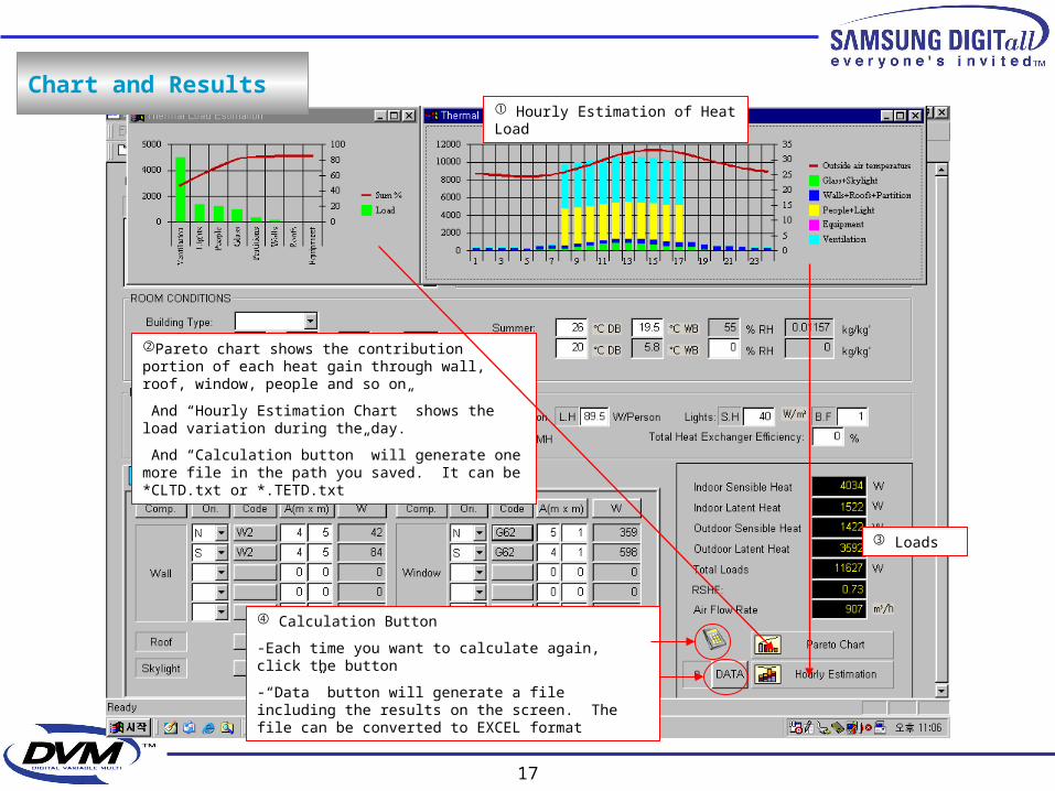
Chart and Results
Loads
Calculation Button
-Each time you want to calculate again, click the button
-“Data” button will generate a file including the results on the screen. The file can be converted to EXCEL format
Pareto chart shows the contribution portion of each heat gain through wall, roof, window, people and so on
And “Hourly Estimation Chart” shows the load variation during the day.
And “Calculation button” will generate one more file in the path you saved. It can be *CLTD.txt or *.TETD.txt
Hourly Estimation of Heat Load
18
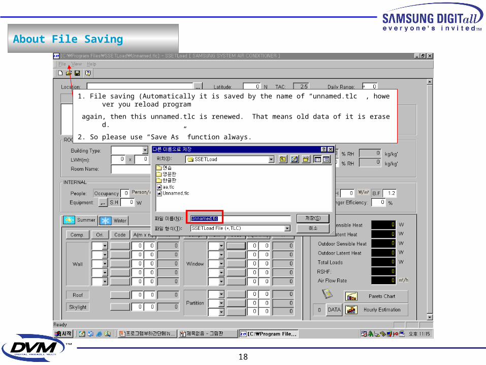
About File Saving
1. File saving (Automatically it is saved by the name of “unnamed.tlc” , however you reload program
again, then this unnamed.tlc is renewed. That means old data of it is erased.
2. So please use “Save As” function always.
19
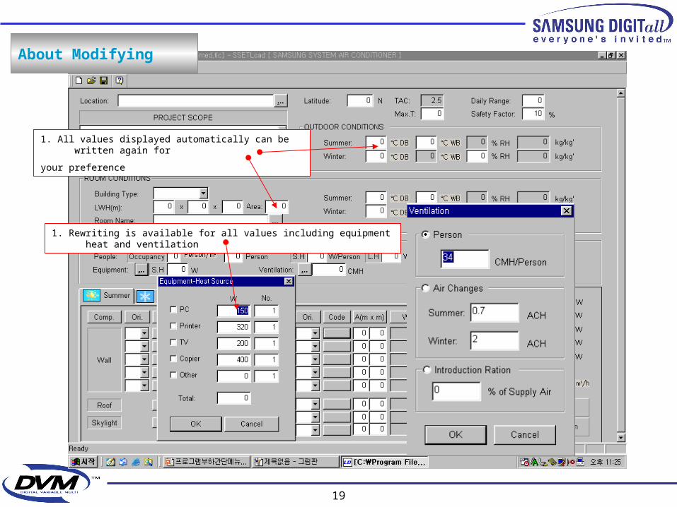
1. All values displayed automatically can be written again for
your preference
1. Rewriting is available for all values including equipment heat and ventilation
About Modifying
20
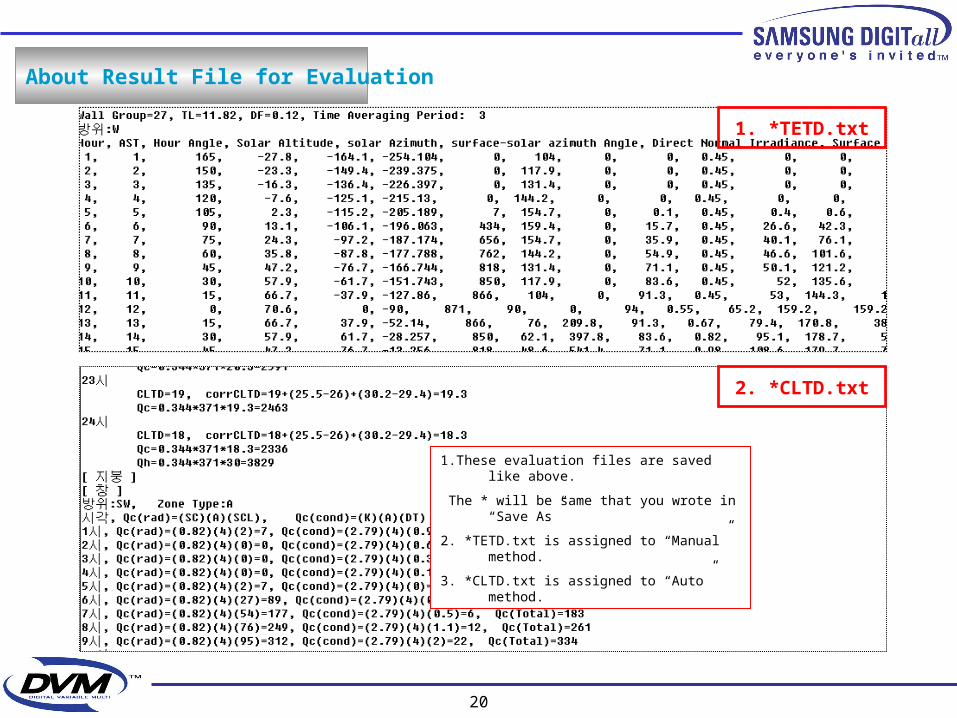
About Result File for Evaluation
1. *TETD.txt
2. *CLTD.txt
1.These evaluation files are saved like above.
The * will be same that you wrote in “Save As”
2. *TETD.txt is assigned to “Manual” method.
3. *CLTD.txt is assigned to “Auto” method.
21
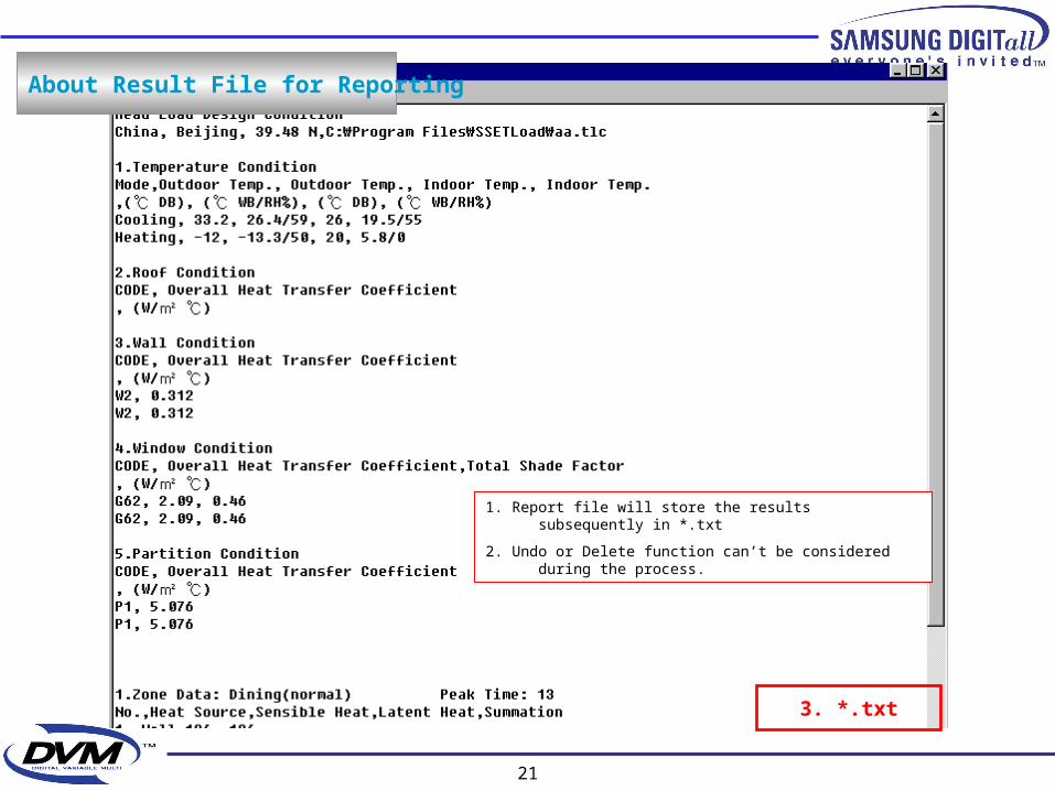
3. *.txt
About Result File for Reporting
1. Report file will store the results subsequently in *.txt
2. Undo or Delete function can’t be considered during the process.