0° DANGER - Lumascape void if not installed as per installation instructions Lumascape Lighting...
2
Warranty void if not installed as per installation instructions INSTALLATION INSTRUCTIONS Lumascape Lighting Industries Pty Ltd 38-44 Enterprise Street, Cleveland, QLD 4163, Australia PO Box 1875, Cleveland D.C., QLD 4163, Australia T 07 3286 2299 F 07 3286 6599 E [email protected] W www.lumascape.com.au IN0008 - 4 June 2014 Copyright ©2014 Lumascape Lighting Industries Pty. Ltd. ABN 21 010 572 773 www.lumascape.com.au LANDSCAPE MODEL: LS9402LED INSTRUCTIONS COVER: 12 V AC or 24 V DC Dimmable A.C.N. 0105 72 773 0° 200 mm 110 mm 110 mm 30° 200 mm LS9402LED: Vedita Spike Mount IP68 Use a Lumascape supplied 24 V DC ripple free power supply or Lumascape magnetic transformer, locate centrally in relation to the luminaires. NOTE: Generally 24 V DC ripple free power supplies should be installed in a well ventilated fully under cover environment. NOTE: DC Power supplies are more efficient than AC transformers. Under no circumstances can an ‘electronic’ transformer be used, this may damage the product. Mark actual locations of luminaires to be installed. Using the charts overleaf calculate the cable size on each run including all luminaires to be connected to a run of cable. Use the same chart to select power supply.. Lay cable from power supply/transformer for each cable run. NOTE: If dimming is required then four conductors will be required. For non-dimmed (usual installation) only two conductors are required. Dimming circuit can use 1 mm cable. When installing each luminaire, leave enough cable at each luminaire location to allow for future re-positioning as your garden matures (1 m is usually plenty). 1x spike 1x drift 1x head 1x luminaire Note: Fixture uses intelligent driver. Always leave on for 20 seconds unless programing. 1. 2. 3. Feed cable of LS9402LED through head and insert LS9402LED fully. Slide head onto spike. NOTE: the head can be slid onto the spike in two directions to provide a vertical or 30° orientations. If difficult to push fully into ground by hand, push in enough to maintain desired orientation. Remove head from spike. Place drift over spike and strike drift with hammer until spike is home. Reattach head and check aiming. 4. 5. Switch on and check each luminaire is operating. At night, adjust and aim you luminaires to achieve the desired effect. 7. DANGER ISOLATE LUMINAIRE FROM POWER Failure to isolate power supply before installation or maintenance may result in fire, serious injury, electric shock, death and may damage the luminaire. WARNING It is strongly recommended to use Lu- mascape power supply or transformer Use of electronic transformer will per- manently damage luminaire All connections must be kept dry; failure to do so may result in product reliability issues Opening luminaire will void warranty Connect the luminaire to the supply cable using the wire nuts supplied. Any joint must be dry and water tight or warranty will be void. NOTE: The orange and grey wires are for optional PWM digital dimming using 0-10 V. Lumascape accessory LS6125 is required. 6. If dimming is not required, do not connect the orange and grey wires. In all cases they are to be sealed and kept dry. Failure to do so will result in the T5 smart driver dimming the lumi- naire due to a voltage differential between the two conductors.
Transcript of 0° DANGER - Lumascape void if not installed as per installation instructions Lumascape Lighting...
Warranty void if not installed as per installation instructions
INSTALLATION INSTRUCTIONSLumascape Lighting Industries Pty Ltd38-44 Enterprise Street, Cleveland, QLD 4163, AustraliaPO Box 1875, Cleveland D.C., QLD 4163, AustraliaT 07 3286 2299F 07 3286 6599E [email protected] www.lumascape.com.au
IN0008 - 4 June 2014Copyright ©2014 Lumascape Lighting Industries Pty. Ltd. ABN 21 010 572 773www.lumascape.com.au
LANDSCAPEMODEL: LS9402LED
INSTRUCTIONS COVER: 12 V AC or 24 V DC DimmableA.C.N. 0105 72 773
110
mm
30°0°
200 mm 200 mm
110 mm
110
mm
30°0°
200 mm 200 mm
110 mm
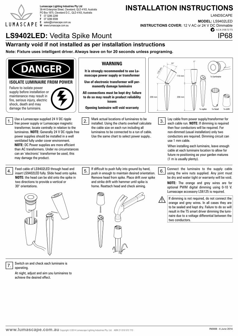
LS9402LED: Vedita Spike Mount IP68
Use a Lumascape supplied 24 V DC ripple free power supply or Lumascape magnetic transformer, locate centrally in relation to the luminaires. NOTE: Generally 24 V DC ripple free power supplies should be installed in a well ventilated fully under cover environment. NOTE: DC Power supplies are more efficient than AC transformers. Under no circumstances can an ‘electronic’ transformer be used, this may damage the product.
Mark actual locations of luminaires to be installed. Using the charts overleaf calculate the cable size on each run including all luminaires to be connected to a run of cable. Use the same chart to select power supply..
Lay cable from power supply/transformer for each cable run. NOTE: If dimming is required then four conductors will be required. For non-dimmed (usual installation) only two conductors are required. Dimming circuit can use 1 mm cable.
When installing each luminaire, leave enough cable at each luminaire location to allow for future re-positioning as your garden matures (1 m is usually plenty).
1x spike 1x drift1x head
1x luminaire
Note: Fixture uses intelligent driver. Always leave on for 20 seconds unless programing.
1. 2. 3.
Feed cable of LS9402LED through head and insert LS9402LED fully. Slide head onto spike. NOTE: the head can be slid onto the spike in two directions to provide a vertical or 30° orientations.
If difficult to push fully into ground by hand, push in enough to maintain desired orientation. Remove head from spike. Place drift over spike and strike drift with hammer until spike is home. Reattach head and check aiming.
4. 5.
Switch on and check each luminaire is operating.
At night, adjust and aim you luminaires to achieve the desired effect.
7.
DANGERISOLATE LUMINAIRE FROM POWERFailure to isolate power supply before installation or maintenance may result in fire, serious injury, electric shock, death and may damage the luminaire.
WARNINGIt is strongly recommended to use Lu-mascape power supply or transformer
Use of electronic transformer will per-manently damage luminaire
All connections must be kept dry; failure to do so may result in product reliability
issues
Opening luminaire will void warranty
Connect the luminaire to the supply cable using the wire nuts supplied. Any joint must be dry and water tight or warranty will be void.
NOTE: The orange and grey wires are for optional PWM digital dimming using 0-10 V. Lumascape accessory LS6125 is required.
6.
If dimming is not required, do not connect the orange and grey wires. In all cases they are to be sealed and kept dry. Failure to do so will result in the T5 smart driver dimming the lumi-naire due to a voltage differential between the two conductors.
IN0008 - 4 June 2014Copyright ©2014 Lumascape Lighting Industries Pty. Ltd. ABN 21 010 572 773www.lumascape.com.au
WARNING - To reduce the risk of FIRE or INJURY:1. Luminaires and transformers to be installed by licensed electrical contractors.2. Luminaires to be used for intended purpose only. 3. Do not operate the luminaires with a missing or damaged parts.4. Use only genuine Lumascape parts to replace damaged or missing components.5. Refer to instructions for installation and operating requirements.6. Ensure installation complies with local regulations
Voltage insulation test (megger) will permanently damage product and will void warranty.
SAVE THESE INSTRUCTIONS.
SAFETY INSTRUCTIONS
Questions?Call +61 7 3286 2299
Email [email protected]
LS100DCLS22TXLS50TXLS100TXLS200TX
orange (PWM _)
240 V AC
LS6122wall plate dimmer
0-10 V signal
OR
240 V AC
red / white +
grey (PWM +)
black _
Power supply Options:
When dimming is NOTrequired, DO NOT connect.
LS6125Dimmer system
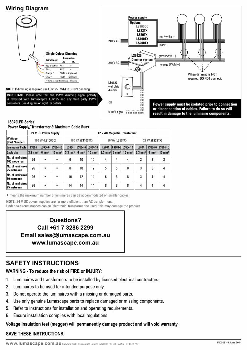
• means the maximum number of luminaires can be accommodated on smaller cables.
LS940LED SeriesPower Supply/ Transformer & Maximum Cable Runs
24 V DC Power Supply 12 V AC Magnetic Transformer
Wattage (Part Number) 100 W (LS100DC) 100 VA (LS100TX) 50 VA (LS50TX) 22 VA (LS22TX)
Lumascape Cable LS604 LS604-6 LS604-10 LS604 LS604-6 LS604-10 LS604 LS604-6 LS604-10 LS604 LS604-6 LS604-10
Cable size 3.3 mm2 6 mm2 10 mm2 3.3 mm2 6 mm2 10 mm2 3.3 mm2 6 mm2 10 mm2 3.3 mm2 6 mm2 10 mm2
No. of luminaires100 metre run 26 • • 6 10 10 4 4 4 2 3 3
No. of luminaires 75 metre run 26 • • 8 10 12 5 5 8 3 3 4
No. of luminaires 50 metre run 26 • • 10 12 14 6 8 8 3 4 4
No. of luminaires 25 metre run 26 • • 14 14 14 8 8 8 4 4 4
NOTE: 24 V DC power supplies are far more efficient than AC transformers. Under no circumstances can an ‘electronic’ transformer be used; this may damage the product
IMPORTANT: Please note that the PWM dimming signal polarity is reversed with Lumascape’s LS6125 and any third party PWM controllers. See diagram on right for details.
NOTE: If dimming is required use LS6125 PWM to 0-10 V dimming.
Wiring Diagram
Single Colour Dimming
Wire ColourDesignation
AC DC
Red or White AC1 +
Black AC2 -
Orange (1) PWM + (optional)
Grey (1) PWM - (optional)
(1) Do not connect if dimming is not required
Power supply must be isolated prior to connection or disconnection of cables. Failure to do so will result in damage to the luminaire components.