Standard - PS 3.3-2004 Digital Imaging and - Dicom - NEMA
876
- Standard - PS 3.3-2004 Digital Imaging and Communications in Medicine (DICOM) Part 3: Information Object Definitions Published by National Electrical Manufacturers Association 1300 N. 17th Street Rosslyn, Virginia 22209 USA © Copyright 2004 by the National Electrical Manufacturers Association. All rights including translation into other languages, reserved under the Universal Copyright Convention, the Berne Convention or the Protection of Literacy and Artistic Works, and the International and Pan American Copyright Conventions.
Transcript of Standard - PS 3.3-2004 Digital Imaging and - Dicom - NEMA

- Standard -
PS 3.3-2004
Digital Imaging and Communications in Medicine (DICOM)
Part 3: Information Object Definitions
Published by
National Electrical Manufacturers Association 1300 N. 17th Street Rosslyn, Virginia 22209 USA
© Copyright 2004 by the National Electrical Manufacturers Association. All rights including translation into other languages, reserved under the Universal Copyright Convention, the Berne Convention or the Protection of Literacy and Artistic Works, and the International and Pan American Copyright Conventions.

PS 3.3 - 2004 Page 2
NOTICE AND DISCLAIMER
The information in this publication was considered technically sound by the consensus of persons engaged in the development and approval of the document at the time it was developed. Consensus does not necessarily mean that there is unanimous agreement among every person participating in the development of this document.
NEMA standards and guideline publications, of which the document contained herein is one, are developed through a voluntary consensus standards development process. This process brings together volunteers and/or seeks out the views of persons who have an interest in the topic covered by this publication. While NEMA administers the process and establishes rules to promote fairness in the development of consensus, it does not write the document and it does not independently test, evaluate, or verify the accuracy or completeness of any information or the soundness of any judgments contained in its standards and guideline publications.
NEMA disclaims liability for any personal injury, property, or other damages of any nature whatsoever, whether special, indirect, consequential, or compensatory, directly or indirectly resulting from the publication, use of, application, or reliance on this document. NEMA disclaims and makes no guaranty or warranty, expressed or implied, as to the accuracy or completeness of any information published herein, and disclaims and makes no warranty that the information in this document will fulfill any of your particular purposes or needs. NEMA does not undertake to guarantee the performance of any individual manufacturer or seller’s products or services by virtue of this standard or guide.
In publishing and making this document available, NEMA is not undertaking to render professional or other services for or on behalf of any person or entity, nor is NEMA undertaking to perform any duty owed by any person or entity to someone else. Anyone using this document should rely on his or her own independent judgment or, as appropriate, seek the advice of a competent professional in determining the exercise of reasonable care in any given circumstances. Information and other standards on the topic covered by this publication may be available from other sources, which the user may wish to consult for additional views or information not covered by this publication.
NEMA has no power, nor does it undertake to police or enforce compliance with the contents of this document. NEMA does not certify, test, or inspect products, designs, or installations for safety or health purposes. Any certification or other statement of compliance with any health or safety–related information in this document shall not be attributable to NEMA and is solely the responsibility of the certifier or maker of the statement.

PS 3.3 - 2004 Page 3
CONTENTS
NOTICE AND DISCLAIMER......................................................................................................................... 2 CONTENTS .................................................................................................................................................. 3 FOREWORD............................................................................................................................................... 31 1 Scope and field of application .............................................................................................................. 33 2 Normative references ........................................................................................................................... 33 3 Definitions ............................................................................................................................................. 35
3.1 REFERENCE MODEL DEFINITIONS..................................................................................... 35 3.2 SERVICE CONVENTIONS DEFINITIONS ............................................................................. 36 3.3 DICOM INTRODUCTION AND OVERVIEW DEFINITIONS................................................... 36 3.4 DICOM SERVICE CLASS SPECIFICATIONS........................................................................ 36 3.5 DICOM DATA STRUCTURES AND ENCODING................................................................... 36 3.6 DICOM MESSAGE EXCHANGE ............................................................................................ 37 3.7 DICOM UPPER LAYER SERVICE ......................................................................................... 37 3.8 DICOM INFORMATION OBJECT........................................................................................... 37 3.9 CHARACTER HANDLING DEFINITIONS .............................................................................. 38 3.10 RADIOTHERAPY .................................................................................................................... 38 3.11 MACROS................................................................................................................................. 38 3.12 DICOM GRAYSCALE STANDARD DISPLAY FUNCTION..................................................... 38 3.13 CODES AND CONTROLLED TERMINOLOGY DEFINITIONS:............................................. 39 3.14 REFERENCE MODEL SECURITY ARCHITECTURE DEFINITIONS.................................... 39 3.15 SECURITY DEFINITIONS....................................................................................................... 40 3.16 DICOM SECURITY PROFILES .............................................................................................. 40 3.17 MULTI-DIMENSIONAL DEFINITIONS......................................................................................... 40
4 Symbols and abbreviations .................................................................................................................. 40 5 Conventions.......................................................................................................................................... 42
5.1 ENTITY-RELATIONSHIP MODEL .......................................................................................... 42 5.1.1 ENTITY ............................................................................................................................. 42 5.1.2 RELATIONSHIP................................................................................................................ 42
5.2 SEQUENCES .......................................................................................................................... 43 5.3 TRIPLET ENCODING OF STRUCTURED DATA (RETIRED) ............................................... 44 5.4 ATTRIBUTE MACROS............................................................................................................ 44
6 DICOM information model .................................................................................................................... 46 6.1 INFORMATION OBJECT DEFINITION................................................................................... 46
6.1.1 COMPOSITE IOD ............................................................................................................. 46 6.1.2 NORMALIZED IOD ........................................................................................................... 47
6.2 ATTRIBUTES .......................................................................................................................... 47 6.3 ON-LINE COMMUNICATION AND MEDIA STORAGE SERVICES ...................................... 47
6.3.1 DIMSE-C SERVICES........................................................................................................ 48

PS 3.3 - 2004 Page 4
6.3.2 DIMSE-N SERVICES........................................................................................................ 48 6.4 DIMSE SERVICE GROUP ...................................................................................................... 48 6.5 SERVICE-OBJECT PAIR (SOP) CLASS................................................................................ 48
6.5.1 NORMALIZED AND COMPOSITE SOP CLASSES......................................................... 48 6.6 ASSOCIATION NEGOTIATION .............................................................................................. 48 6.7 SERVICE CLASS SPECIFICATION ....................................................................................... 48
7 DICOM model of the real-world............................................................................................................ 49 7.1 DICOM INFORMATION MODEL ............................................................................................ 55 7.2 ORGANIZATION OF ANNEXES A, B AND C......................................................................... 55 7.3 EXTENSION OF THE DICOM MODEL OF THE REAL-WORLD ........................................... 55
7.3.1 Definition of the Extensions of the DICOM Real-World Model ......................................... 56 7.3.1.1 PATIENT ................................................................................................................. 56 7.3.1.2 SERVICE EPISODE................................................................................................ 56 7.3.1.3 IMAGING SERVICE REQUEST ............................................................................. 56 7.3.1.4 PROCEDURE TYPE............................................................................................... 57 7.3.1.5 REQUESTED PROCEDURE.................................................................................. 57 7.3.1.6 SCHEDULED PROCEDURE STEP ....................................................................... 57 7.3.1.7 PROCEDURE PLAN............................................................................................... 58 7.3.1.8 PROTOCOL ............................................................................................................ 58 7.3.1.9 MODALITY PERFORMED PROCEDURE STEP ................................................... 58 7.3.1.10 GENERAL PURPOSE SCHEDULED PROCEDURE STEP .................................. 58 7.3.1.11 GENERAL PURPOSE PERFORMED PROCEDURE STEP.................................. 59 7.3.1.12 WORKITEM............................................................................................................. 59
7.4 EXTENSION OF THE DICOM MODEL OF THE REAL-WORLD FOR THE GENERAL PURPOSE WORKLIST........................................................................................................................................... 59 7.5 ORGANIZING LARGE SETS OF INFORMATION.................................................................. 62
7.5.1 CONCATENATION .................................................................................................... 62 7.5.2 DIMENSION ORGANIZATION................................................................................... 62
7.6 EXTENSION OF THE DICOM MODEL OF THE REAL WORLD FOR CLINICAL TRIALS........... 63 7.6.1 Clinical Trial Information Entities .......................................................................................... 64
7.6.1.1 Clinical Trial Sponsor .................................................................................................. 64 7.6.1.2 Clinical Trial Protocol................................................................................................... 64 7.6.1.3 Clinical Trial Subject .................................................................................................... 64 7.6.1.4 Clinical Trial Site.......................................................................................................... 64 7.6.1.5 Clinical Trial Time Point............................................................................................... 65 7.6.1.6 Clinical Trial Coordinating Center ............................................................................... 65
8 Encoding of Coded Entry Data............................................................................................................. 66 8.1 CODE VALUE ......................................................................................................................... 66 8.2 CODING SCHEME DESIGNATOR AND CODING SCHEME VERSION............................... 66 8.3 CODE MEANING .................................................................................................................... 67 8.4 MAPPING RESOURCE........................................................................................................... 67 8.5 CONTEXT GROUP VERSION................................................................................................ 68 8.6 CONTEXT IDENTIFIER .......................................................................................................... 68 8.7 CONTEXT GROUP EXTENSIONS......................................................................................... 68 8.8 STANDARD ATTRIBUTE SETS FOR CODE SEQUENCE ATTRIBUTES ............................ 68
9 TEMPLATE IDENTIFICATION MACRO .............................................................................................. 69 10 MISCELLANEOUS MACROS .............................................................................................................. 70
10.1 PERSON IDENTIFICATION MACRO ..................................................................................... 70

PS 3.3 - 2004 Page 5
10.2 CONTENT ITEM MACRO ....................................................................................................... 71 10.3 IMAGE SOP INSTANCE REFERENCE MACRO ................................................................... 72 10.4 SERIES AND INSTANCE REFERENCE MACRO.................................................................. 72 10.5 GENERAL ANATOMY MACROS............................................................................................ 73
Annex A Composite information object definitions (Normative)............................................................. 76 A.1 ELEMENTS OF AN INFORMATION OBJECT DEFINITION.................................................. 76
A.1.1 IOD Description................................................................................................................. 76 A.1.2 IOD Entity-Relationship Model.......................................................................................... 76
A.1.2.1 PATIENT IE............................................................................................................. 77 A.1.2.2 STUDY IE................................................................................................................ 77 A.1.2.3 SERIES IE............................................................................................................... 78 A.1.2.4 EQUIPMENT IE....................................................................................................... 78 A.1.2.5 FRAME OF REFERENCE IE .................................................................................. 78 A.1.2.6 IMAGE IE ................................................................................................................ 79 A.1.2.7 OVERLAY IE ........................................................................................................... 79 A.1.2.8 CURVE IE ............................................................................................................... 79 A.1.2.9 MODALITY LUT IE.................................................................................................. 79 A.1.2.10 VOI LUT IE .............................................................................................................. 80 A.1.2.11 PRESENTATION STATE IE ................................................................................... 80 A.1.2.12 WAVEFORM IE....................................................................................................... 80 A.1.2.13 SR DOCUMENT IE ................................................................................................. 80 A.1.2.14 MR Spectroscopy IE ............................................................................................... 80 A.1.2.15 Raw Data IE ............................................................................................................ 80
A.1.3 IOD Module Table and Functional Group Macro Table.................................................... 81 A.1.3.1 MANDATORY MODULES ...................................................................................... 81 A.1.3.2 CONDITIONAL MODULES..................................................................................... 81 A.1.3.3 USER OPTION MODULES..................................................................................... 81
A.1.4 Overview of the Composite IOD Module Content............................................................. 81 A.2 COMPUTED RADIOGRAPHY IMAGE INFORMATION OBJECT DEFINITION .................... 95
A.2.1 CR Image IOD Description ............................................................................................... 95 A.2.2 CR Image IOD Entity-Relationship Model ........................................................................ 95 A.2.3 CR Image IOD Module Table............................................................................................ 95
A.3 COMPUTED TOMOGRAPHY IMAGE INFORMATION OBJECT DEFINITION..................... 95 A.3.1 CT Image IOD Description................................................................................................ 95 A.3.2 CT image IOD Entity-Relationship Model ......................................................................... 96 A.3.3 CT Image IOD Module Table ............................................................................................ 96
A.4 MAGNETIC RESONANCE IMAGE INFORMATION OBJECT DEFINITION.......................... 96 A.4.1 MR Image IOD Description ............................................................................................... 96 A.4.2 MR image IOD Entity-Relationship Model ........................................................................ 96 A.4.3 MR Image IOD Module Table ........................................................................................... 97
A.5 NUCLEAR MEDICINE IMAGE INFORMATION OBJECT DEFINITION................................. 97 A.5.1 NM Image IOD Description ............................................................................................... 97 A.5.2 NM Image IOD Entity-Relationship Model ........................................................................ 97 A.5.3 NM Image IOD Module Table (Retired) ............................................................................ 97 A.5.4 NM Image IOD Module Table ........................................................................................... 98
A.5.4.1 Acquisition Context Module..................................................................................... 99 A.6 ULTRASOUND IMAGE INFORMATION OBJECT DEFINITION............................................ 99
A.6.1 US Image IOD Description................................................................................................ 99 A.6.2 US Image IOD Entity-Relationship Model......................................................................... 99 A.6.3 US Image IOD Module Table (Retired)............................................................................. 99 A.6.4 US Image IOD Module Table.......................................................................................... 100
A.6.4.1 Mutually Exclusive IEs .......................................................................................... 101

PS 3.3 - 2004 Page 6
A.7 ULTRASOUND MULTI-FRAME IMAGE INFORMATION OBJECT DEFINITION ................ 101 A.7.1 US Image IOD Description.............................................................................................. 101 A.7.2 US Multi-Frame Image IOD Entity-Relationship Model .................................................. 101 A.7.3 US Image IOD Module Table (Retired)........................................................................... 101 A.7.4 US Multi-Frame Image IOD Module Table ..................................................................... 102
A.7.4.1 Mutually Exclusive IEs .......................................................................................... 103 A.8 SECONDARY CAPTURE IMAGE INFORMATION OBJECT DEFINITION.......................... 103
A.8.1 SC Image Information Objection Definition..................................................................... 103 A.8.1.1 SC Image IOD Description.................................................................................... 103 A.8.1.2 SC Image IOD Entity-Relationship Model............................................................. 103 A.8.1.3 SC Image IOD Module Table ................................................................................ 104
A.8.2 Multi-frame Single Bit SC Image Information Object Definition ...................................... 104 A.8.2.1 Multi-frame Single Bit SC Image IOD Description ................................................ 104 A.8.2.2 Multi-frame Single Bit SC Image IOD Entity-Relationship Model ......................... 104 A.8.2.3 Multi-frame Single Bit SC Image IOD Module Table............................................. 105 A.8.2.4 Multi-frame Single Bit SC Image IOD Content Constraints .................................. 105
A.8.3 Multi-frame Grayscale Byte SC Image Information Object Definition............................. 106 A.8.3.1 Multi-frame Grayscale Byte Image IOD Description ............................................. 106 A.8.3.2 Multi-frame Grayscale Byte SC Image IOD Entity-Relationship Model ................ 106 A.8.3.3 Multi-frame Grayscale Byte SC Image IOD Module Table ................................... 106 A.8.3.4 Multi-frame Grayscale Byte SC Image IOD Content Constraints ......................... 107
A.8.4 Multi-frame Grayscale Word SC Image Information Object Definition ........................... 107 A.8.4.1 Multi-frame Grayscale Word SC Image IOD Description...................................... 107 A.8.4.2 Multi-frame Grayscale Word SC Image IOD Entity-Relationship Model............... 107 A.8.4.3 Multi-frame Grayscale Word SC Image IOD Module Table.................................. 108 A.8.4.4 Multi-frame Grayscale Word SC Image IOD Content Constraints........................ 108
A.8.5 Multi-frame True Color SC Image Information Object Definition .................................... 109 A.8.5.1 Multi-frame True Color Image IOD Description .................................................... 109 A.8.5.2 Multi-frame True Color SC Image IOD Entity-Relationship Model ....................... 109 A.8.5.3 Multi-frame True Color SC Image IOD Module Table........................................... 109 A.8.5.4 Multi-frame True Color SC Image IOD Content Constraints................................. 109
A.9 STANDALONE OVERLAY INFORMATION OBJECT DEFINITION..................................... 110 A.9.1 Standalone Overlay IOD Description.............................................................................. 110 A.9.2 Standalone Overlay IOD Entity-Relationship Model....................................................... 110 A.9.3 Standalone Overlay IOD Module Table .......................................................................... 110
A.10 STANDALONE CURVE INFORMATION OBJECT DEFINITION ......................................... 111 A.10.1 Standalone Curve IOD Description................................................................................. 111 A.10.2 Standalone Curve IOD Entity-Relationship Model.......................................................... 111 A.10.3 Standalone Curve IOD Module Table............................................................................. 111
A.11 BASIC STUDY DESCRIPTOR INFORMATION OBJECT DEFINITION............................... 112 A.11.1 Basic Study Descriptor IOD Description ......................................................................... 112 A.11.2 Basic Study Descriptor Entity-Relationship Model ......................................................... 112 A.11.3 Basic Study Descriptor IOD Module Table ..................................................................... 112
A.12 STANDALONE MODALITY LUT INFORMATION OBJECT DEFINITION............................ 113 A.12.1 Standalone Modality LUT IOD Description ..................................................................... 113 A.12.2 Standalone Modality LUT IOD Entity-Relationship Model .............................................. 113 A.12.3 Standalone Modality LUT IOD Module Table ................................................................. 113
A.13 STANDALONE VOI LUT INFORMATION OBJECT DEFINITION........................................ 113 A.13.1 Standalone VOI LUT IOD Description ............................................................................ 113 A.13.2 Standalone VOI LUT IOD Entity-Relationship Model ..................................................... 113 A.13.3 Standalone VOI LUT IOD Module Table ........................................................................ 114
A.14 X-RAY ANGIOGRAPHIC IMAGE INFORMATION OBJECT DEFINITION........................... 115 A.14.1 XA Image IOD Description.............................................................................................. 115

PS 3.3 - 2004 Page 7
A.14.2 XA Image IOD Entity-Relationship Model....................................................................... 115 A.14.3 XA Image IOD Module Table .......................................................................................... 116
A.15 X-RAY ANGIOGRAPHIC BI-PLANE IMAGE INFORMATION OBJECT DEFINITION (RETIRED).......................................................................................................................................... 117 A.16 X-RAY RF IMAGE INFORMATION OBJECT DEFINITION................................................... 117
A.16.1 XRF Image IOD Description ........................................................................................... 117 A.16.2 XRF Image IOD Entity-Relationship Model .................................................................... 117 A.16.3 XRF Image IOD Module Table.......................................................................................... 117
A.17 RT IMAGE INFORMATION OBJECT DEFINITION .............................................................. 119 A.17.1 RT Image IOD Description.............................................................................................. 119 A.17.2 RT Image IOD entity-relationship model......................................................................... 119 A.17.3 RT Image IOD Module Table .......................................................................................... 120
A.18 RT DOSE INFORMATION OBJECT DEFINITION ............................................................... 122 A.18.1 RT Dose IOD Description ............................................................................................... 122 A.18.2 RT Dose IOD entity-relationship model .......................................................................... 122 A.18.3 RT Dose IOD Module Table............................................................................................ 123
A.19 RT STRUCTURE SET INFORMATION OBJECT DEFINITION ........................................... 124 A.19.1 RT Structure Set IOD Description................................................................................... 124 A.19.2 RT Structure Set IOD entity-relationship model.............................................................. 124 A.19.3 RT Structure Set IOD Module Table............................................................................... 125
A.20 RT PLAN INFORMATION OBJECT DEFINITION ................................................................ 126 A.20.1 RT Plan IOD Description................................................................................................. 126 A.20.2 RT Plan IOD entity-relationship model ........................................................................... 126 A.20.3 RT Plan IOD Module Table............................................................................................. 127
A.20.3.1 RT FRACTION SCHEME MODULE ..................................................................... 127 A.20.3.2 RT PRESCRIPTION MODULE............................................................................. 128 A.20.3.3 RT TOLERANCE TABLES MODULE ................................................................... 128 A.20.3.4 RT PATIENT SETUP MODULE............................................................................ 128
A.21 POSITRON EMISSION TOMOGRAPHY IMAGE INFORMATION OBJECT DEFINITION.. 129 A.21.1 PET Image IOD Description............................................................................................ 129 A.21.2 PET Image IOD Entity-Relationship Model..................................................................... 129 A.21.3 PET Image IOD Module Table........................................................................................ 129
A.22 STANDALONE PET CURVE INFORMATION OBJECT DEFINITION ................................. 130 A.22.1 Standalone PET Curve IOD Description......................................................................... 130 A.22.2 Standalone PET Curve IOD Entity-Relationship Model.................................................. 130 A.22.3 Standalone PET Curve IOD Module Table..................................................................... 130
A.23 STORED PRINT INFORMATION OBJECT DEFINITION..................................................... 130 A.23.1 IOD Description............................................................................................................... 130 A.23.2 Stored Print IOD Entity-Relationship Model.................................................................... 131 A.23.3 IOD Module Table........................................................................................................... 131
A.24 HARDCOPY GRAYSCALE IMAGE INFORMATION OBJECT DEFINITION ....................... 131 A.24.1 IOD Description............................................................................................................... 131 A.24.2 Hardcopy Grayscale Image IOD Entity-Relationship Model........................................... 131 A.24.3 IOD Module Table........................................................................................................... 132
A.25 HARDCOPY COLOR IMAGE INFORMATION OBJECT DEFINITION ................................ 132 A.25.1 IOD Description............................................................................................................... 132 A.25.2 Hardcopy Color Image IOD Entity-Relationship Model .................................................. 132 A.25.3 IOD Module Table........................................................................................................... 133
A.26 DIGITAL X-RAY IMAGE INFORMATION OBJECT DEFINITION......................................... 133 A.26.1 DX Image IOD Description.............................................................................................. 133 A.26.2 DX Image IOD Entity-Relationship Model....................................................................... 134 A.26.3 DX Image IOD Module Table.......................................................................................... 134

PS 3.3 - 2004 Page 8
A.26.4 Overlay Plane Module..................................................................................................... 135 A.27 DIGITAL MAMMOGRAPHY X-RAY IMAGE INFORMATION OBJECT DEFINITION .......... 136
A.27.1 Digital Mammography X-Ray Image IOD Description .................................................... 136 A.27.2 Digital Mammography X-Ray Image IOD Module Table ................................................ 137 A.27.3 Overlay Plane Module..................................................................................................... 138
A.28 DIGITAL INTRA-ORAL X-RAY IMAGE INFORMATION OBJECT DEFINITION.................. 138 A.28.1 Digital Intra-oral X-Ray Image IOD Description.............................................................. 138 A.28.2 Digital Intra-oral X-Ray Image IOD Module Table .......................................................... 139 A.28.3 Overlay Plane Module..................................................................................................... 140
A.29 RT BEAMS TREATMENT RECORD INFORMATION OBJECT DEFINITION ..................... 140 A.29.1 RT Beams Treatment Record IOD Description .............................................................. 140 A.29.2 RT Beams Treatment Record IOD entity-relationship model ......................................... 140 A.29.3 RT Beams Treatment Record IOD Module Table .......................................................... 142
A.30 RT BRACHY TREATMENT RECORD INFORMATION OBJECT DEFINITION................... 142 A.30.1 RT Brachy Treatment Record IOD Description .............................................................. 142 A.30.2 RT Brachy Treatment Record IOD entity-relationship model ......................................... 142 A.30.3 RT Brachy Treatment Record IOD Module Table .......................................................... 144
A.31 RT TREATMENT SUMMARY RECORD INFORMATION OBJECT DEFINITION ............... 144 A.31.1 RT Treatment Summary Record IOD Description .......................................................... 144 A.31.2 RT Treatment Summary Record IOD entity-relationship model ..................................... 144 A.31.3 RT Treatment Summary Record IOD Module Table ...................................................... 145
A.32 VISIBLE LIGHT IMAGE INFORMATION OBJECT DEFINITIONS ....................................... 145 A.32.1 VL Endoscopic Image Information Object Definition ...................................................... 146
A.32.1.1 VL Endoscopic Image IOD Description................................................................. 146 A.32.1.2 VL Endoscopic Image IOD Entity-Relationship Model.......................................... 146 A.32.1.3 VL Endoscopic Image IOD Content Constraints................................................... 147
A.32.1.3.1 Modality................................................................................................ 147 A.32.2 VL Microscopic Image Information Object Definition...................................................... 147
A.32.2.1 VL Microscopic Image IOD Description ................................................................ 147 A.32.2.2 VL Microscopic Image IOD Entity-Relationship Model ......................................... 147 A.32.2.3 VL Microscopic Image IOD Content Constraints .................................................. 148
A.32.2.3.1 Modality................................................................................................ 148 A.32.3 VL Slide-Coordinates Microscopic Image Information Object Definition ........................ 148
A.32.3.1 VL Slide-Coordinates Microscopic Image IOD Description .................................. 148 A.32.3.2 VL Slide-Coordinates Microscopic Image IOD Entity-Relationship Model ........... 148 A.32.3.3 VL Slide-Coordinates Microscopic Image IOD Content Constraints .................... 149
A.32.3.3.1 Modality................................................................................................ 149 A.32.4 VL Photographic Image Information Object Definition.................................................... 149
A.32.4.1 VL Photographic Image IOD Description .............................................................. 149 A.32.4.2 VL Photographic Image IOD Entity-Relationship Model ....................................... 149 A.32.4.3 VL Photographic Image IOD Content Constraints ................................................ 150
A.32.4.3.1 Modality................................................................................................ 150 A.32.5 Video Endoscopic Image Information Object Definition ................................................. 150
A.32.5.1 Video Endoscopic Image IOD Description............................................................ 150 A.32.5.2 Video Endoscopic Image IOD Entity-Relationship Model..................................... 150 A.32.5.3 Video Endoscopic Image IOD Content Constraints.............................................. 151
A.32.5.3.1 Modality................................................................................................ 151 A.32.5.3.2 Image Related Data Encoding........................................................................... 151
A.32.5.3.3 Anatomic Region Sequence ................................................................ 151 A.32.6 Video Microscopic Image Information Object Definition ................................................. 151
A.32.6.1 Video Microscopic Image IOD Description ........................................................... 151 A.32.6.2 Video Microscopic Image IOD Entity-Relationship Model .................................... 151 A.32.6.3 Video Microscopic Image IOD Content Constraints ............................................. 152
A.32.6.3.1 Modality................................................................................................ 152

PS 3.3 - 2004 Page 9
A.32.6.3.2 Image Related Data Encoding........................................................................... 152 A.32.7 Video Photographic Image Information Object Definition............................................... 152
A.32.7.1 Video Photographic Image IOD Description ......................................................... 152 A.32.7.2 Video Photographic Image IOD Entity-Relationship Model .................................. 152 A.32.7.3 Video Photographic Image IOD Content Constraints ........................................... 153
A.32.7.3.1 Modality................................................................................................ 153 A.32.7.3.2 Image Related Data Encoding........................................................................... 153
A.33 GRAYSCALE SOFTCOPY PRESENTATION STATE INFORMATION OBJECT DEFINITION154 A.33.1 Grayscale Softcopy Presentation State IOD Description ............................................... 154 A.33.2 Grayscale Softcopy Presentation State IOD Module Table............................................ 155
A.34 WAVEFORM INFORMATION OBJECT DEFINITIONS ............................................................ 157 A.34.1 Waveform IOD Entity-Relationship Model........................................................................ 157 A.34.2 Basic Voice Audio Information Object Definition.............................................................. 157
A.34.2.1 Basic Voice Audio IOD Description ........................................................................ 157 A.34.2.2 Basic Voice Audio IOD Entity-Relationship Model ................................................. 157 A.34.2.3 Basic Voice Audio IOD Module Table..................................................................... 157 A.34.2.4 Basic Voice Audio IOD Content Constraints........................................................... 158
A.34.2.4.1 Modality................................................................................................ 158 A.34.2.4.2 Waveform Sequence ........................................................................... 158 A.34.2.4.3 Number of Waveform Channels .......................................................... 158 A.34.2.4.4 Sampling Frequency............................................................................ 158 A.34.2.4.5 Waveform Sample Interpretation......................................................... 158
A.34.3 12-Lead Electrocardiogram Information Object Definition ............................................... 158 A.34.3.1 12-Lead ECG IOD Description ............................................................................... 158 A.34.3.2 12-Lead ECG IOD Entity-Relationship Model......................................................... 158 A.34.3.3 12-Lead ECG IOD Module Table............................................................................ 158 A.34.3.4 12-Lead ECG IOD Content Constraints.................................................................. 159
A.34.3.4.1 Modality................................................................................................ 159 A.34.3.4.2 Acquisition Context Module ................................................................. 159 A.34.3.4.3 Waveform Sequence ........................................................................... 159 A.34.3.4.4 Number of Waveform Channels .......................................................... 159 A.34.3.4.5 Number of Waveform Samples ........................................................... 160 A.34.3.4.6 Sampling Frequency............................................................................ 160 A.34.3.4.7 Channel Source ................................................................................... 160 A.34.3.4.8 Waveform Sample Interpretation......................................................... 160 A.34.3.4.9 Waveform Annotation Module ............................................................. 160
A.34.4 General Electrocardiogram Information Object Definition................................................ 161 A.34.4.1 General ECG IOD Description................................................................................ 161 A.34.4.2 General ECG IOD Entity-Relationship Model ......................................................... 161 A.34.4.3 General ECG IOD Module Table ............................................................................ 161 A.34.4.4 General ECG IOD Content Constraints .................................................................. 161
A.34.4.4.1 Modality................................................................................................ 161 A.34.4.4.2 Waveform Sequence ........................................................................... 161 A.34.4.4.3 Number of Waveform Channels .......................................................... 161 A.34.4.4.4 Sampling Frequency............................................................................ 161 A.34.4.4.5 Channel Source ................................................................................... 162 A.34.4.4.6 Waveform Sample Interpretation......................................................... 162 A.34.4.4.7 Waveform Annotation Module ............................................................. 162
A.34.5 Ambulatory Electrocardiogram Information Object Definition .......................................... 162 A.34.5.1 Ambulatory ECG IOD Description .......................................................................... 162 A.34.5.2 Ambulatory ECG IOD Entity-Relationship Model.................................................... 162 A.34.5.3 Ambulatory ECG IOD Module Table....................................................................... 162 A.34.5.4 Ambulatory ECG IOD Content Constraints............................................................. 163
A.34.5.4.1 Modality................................................................................................ 163 A.34.5.4.2 Waveform Sequence ........................................................................... 163

PS 3.3 - 2004 Page 10
A.34.5.4.3 Number of Waveform Channels .......................................................... 163 A.34.5.4.5 Sampling Frequency............................................................................ 163 A.34.5.4.6 Channel Source ................................................................................... 163 A.34.5.4.7 Waveform Sample Interpretation......................................................... 163
A.34.6 Hemodynamic Information Object Definition.................................................................... 163 A.34.6.1 Hemodynamic IOD Description .............................................................................. 163 A.34.6.2 Hemodynamic IOD Entity-Relationship Model........................................................ 163 A.34.6.3 Hemodynamic IOD Module Table........................................................................... 163 A.34.6.4 Hemodynamic IOD Content Constraints................................................................. 164
A.34.6.4.1 Modality................................................................................................ 164 A.34.6.4.2 Acquisition Context Module ................................................................. 164 A.34.6.4.3 Waveform Sequence ........................................................................... 164 A.34.6.4.4 Number of Waveform Channels .......................................................... 164 A.34.6.4.5 Sampling Frequency............................................................................ 164 A.34.6.4.7 Channel Source ................................................................................... 164 A.34.6.4.8 Waveform Sample Interpretation......................................................... 165 A.34.6.4.9 Waveform Annotation Module ............................................................. 165
A.34.7 Basic Cardiac Electrophysiology Information Object Definition ....................................... 165 A.34.7.1 Basic Cardiac EP IOD Description ......................................................................... 165 A.34.7.2 Basic Cardiac EP IOD Entity-Relationship Model .................................................. 165 A.34.7.3 Basic Cardiac EP IOD Module Table...................................................................... 165 A.34.7.4 Basic Cardiac EP IOD Content Constraints............................................................ 166
A.34.7.4.1 Modality................................................................................................ 166 A.34.7.4.2 Acquisition Context Module ................................................................. 166 A.34.7.4.3 Waveform Sequence ........................................................................... 166 A.34.7.4.4 Sampling Frequency............................................................................ 166 A.34.7.4.5 Channel Source ................................................................................... 166 A.34.7.4.6 Waveform Sample Interpretation......................................................... 166 A.34.7.4.7 Waveform Annotation Module ............................................................. 166
A.35 STRUCTURED REPORT DOCUMENT INFORMATION OBJECT DEFINITIONS................... 167 A.35.1 Basic Text SR Information Object Definition .................................................................... 167
A.35.1.1 Basic Text SR Information Object Description........................................................ 167 A.35.1.2 Basic Text SR IOD Entity-Relationship Model........................................................ 167 A.35.1.3 Basic Text SR IOD Module Table ........................................................................... 167
A.35.1.3.1 Basic Text SR IOD Content Constraints.............................................. 167 A.35.1.3.1.1...Value Type .................................................................................. 167 A.35.1.3.1.2...Relationship Constraints ............................................................. 168
A.35.2 Enhanced SR Information Object Definition..................................................................... 168 A.35.2.1 Enhanced SR Information Object Description ........................................................ 168 A.35.2.2 Enhanced SR IOD Entity-Relationship Model ........................................................ 169 A.35.2.3 Enhanced SR IOD Module Table ........................................................................... 169
A.35.2.3.1 Enhanced SR IOD Content Constraints .............................................. 169 A.35.2.3.1.1...Value Type .................................................................................. 169 A.35.2.3.1.2...Relationship Constraints ............................................................. 170
A.35.3 Comprehensive SR Information Object Definition............................................................ 170 A.35.3.1 Comprehensive SR Information Object Description ............................................... 170 A.35.3.2 Comprehensive SR IOD Entity-Relationship Model ............................................... 171 A.35.3.3 Comprehensive SR IOD Module Table .................................................................. 171
A.35.3.3.1 Comprehensive SR IOD Content Constraints ..................................... 171 A.35.3.3.1.1...Value Type .................................................................................. 171 A.35.3.3.1.2...Relationship Constraints ............................................................. 172
A.35.4 Key Object Selection Document Information Object Definition........................................ 173 A.35.4.1 Key Object Selection Document Information Object Description ........................... 173 A.35.4.2 Key Object Selection Document IOD Entity-Relationship Model............................ 173 A.35.4.3 Key Object Selection Document IOD Module Table............................................... 173

PS 3.3 - 2004 Page 11
A.35.4.3.1 Key Object Selection Document IOD Content Constraints ................. 173 A.35.4.3.1.1...Value Type .................................................................................. 173 A.35.4.3.1.2...Relationship Constraints ............................................................. 174 A.35.4.3.1.3...Template Constraints .................................................................. 174
A.35.5 Mammography CAD SR Information Object Definition .................................................... 174 A.35.5.1 Mammography CAD SR Information Object Description........................................ 174 A.35.5.2 Mammography CAD SR IOD Entity-Relationship Model........................................ 174 A.35.5.3 Mammography CAD SR IOD Module Table ........................................................... 174
A.35.5.3.1 Mammography CAD SR IOD Content Constraints.............................. 175 A.35.5.3.1.1...Template Constraints .................................................................. 175 A.35.5.3.1.2...Value Type .................................................................................. 175 A.35.5.3.1.3...Relationship Constraints ............................................................. 175
A.35.6 Chest CAD SR Information Object Definition................................................................... 176 A.35.6.1 Chest CAD SR Information Object Description ...................................................... 176 A.35.6.2 Chest CAD SR IOD Entity-Relationship Model....................................................... 176 A.35.6.3 Chest CAD SR IOD Module Table.......................................................................... 177
A.35.6.3.1 Chest CAD SR IOD Content Constraints ............................................ 177 A.35.6.3.1.1...Template Constraints .................................................................. 177 A.35.6.3.1.2...Value Type .................................................................................. 177 A.35.6.3.1.3...Relationship Constraints ............................................................. 178
A.35.7 Procedure Log Information Object Definition ................................................................... 178 A.35.7.1 Procedure Log Information Object Description....................................................... 178 A.35.7.2 Procedure Log IOD Entity-Relationship Model ....................................................... 178 A.35.7.3 Procedure Log IOD Module Table .......................................................................... 179
A.35.7.3.1 Procedure Log IOD Content Constraints............................................. 179 A.35.7.3.1.1...Template ..................................................................................... 179 A.35.7.3.1.2...Observation DateTime ................................................................ 179 A.35.7.3.1.3...Value Type .................................................................................. 179 A.35.7.3.1.4...Relationship Constraints ............................................................. 180
A.36 ENHANCED MR INFORMATION OBJECT DEFINITIONS .................................................. 181 A.36.1 Relationship between Enhanced MR IODs .................................................................... 181 A.36.2 Enhanced MR Image Information Object Definition ....................................................... 182
A.36.2.1 Enhanced MR Image IOD Description.................................................................. 182 A.36.2.2 Enhanced MR Image Entity-Relationship Model .................................................. 182 A.36.2.3 Enhanced MR Image IOD Module Table .............................................................. 182
A.36.2.3.1 Enhanced MR Image IOD Content Constraints .................................. 183 A.36.2.4 Enhanced MR Image Functional Group Macros................................................... 184
A.36.3 MR Spectroscopy Information Object Definition............................................................. 185 A.36.3.1 MR Spectroscopy IOD Description ....................................................................... 185 A.36.3.2 MR Spectroscopy entity-relationship model.......................................................... 185 A.36.3.3 MR Spectroscopy IOD Module Table ................................................................... 186 A.36.3.4 MR Spectroscopy Functional Group Macros ........................................................ 187
A.37 RAW DATA INFORMATION OBJECT DEFINITION................................................................. 188 A.37.1 Raw Data IOD Description ............................................................................................... 188 A.37.2 Raw Data entity-relationship model.................................................................................. 188 A.37.3 Raw Data IOD Module Table ........................................................................................... 189
A.38 ENHANCED COMPUTED TOMOGRAPHY IMAGE INFORMATION OBJECT DEFINITION .. 189 A.38.1 Enhanced CT Image Information Object Definition ........................................................ 189
A.38.1.1 Enhanced CT Image IOD Description................................................................... 189 A.38.1.2 Enhanced CT Image IOD Entity-Relationship Model............................................ 189 A.38.1.3 Enhanced CT Image IOD Module Table............................................................... 189
A.38.1.3.1 Enhanced CT Image IOD Content Constraints ................................... 190 A.38.1.4 Enhanced CT Image Functional Group Macros ................................................... 190
A.39 SPATIAL REGISTRATION INFORMATION OBJECT DEFINITION ......................................... 192

PS 3.3 - 2004 Page 12
A.39.1 Spatial Registration IOD Description................................................................................ 192 A.39.2 Spatial Registration IOD Entity-Relationship Model......................................................... 192 A.39.3 Spatial Registration IOD Module Table ............................................................................ 192
A.40 SPATIAL FIDUCIALS INFORMATION OBJECT DEFINITION ................................................. 193 A.40.1 Spatial Fiducials IOD Description..................................................................................... 193 A.40.2 Spatial Fiducials IOD Entity-Relationship Model.............................................................. 194 A.40.3 Spatial Fiducials IOD Module Table ................................................................................. 194
A.41 OPHTHALMIC PHOTOGRAPHY 8 BIT IMAGE INFORMATION OBJECT DEFINITION .... 195 A.41.1 Ophthalmic Photography 8 Bit Image IOD Description .................................................. 195 A.41.2 Ophthalmic Photography 8 Bit Image IOD Entity-Relationship Model ........................... 195 A.41.3 Ophthalmic Photography 8 Bit Image IOD Modules...................................................... 195 A.41.4 Ophthalmic Photography 8 Bit Image IOD Content Constraints .................................... 196
A.41.4.1 Bits Allocated, Bits Stored, and High Bit ............................................................... 196 A.41.4.2 Contrast/Bolus Agent Sequence........................................................................... 196
A.42 OPHTHALMIC PHOTOGRAPHY 16 BIT IMAGE INFORMATION OBJECT DEFINITION .. 196 A.42.1 Ophthalmic Photography 16 Bit Image IOD Description ................................................ 196 A.42.2 Ophthalmic Photography 16 Bit Image IOD Entity-Relationship Model ......................... 196 A.42.3 Ophthalmic Photography 16 Bit Image IOD Modules.................................................... 196 A.42.4 Ophthalmic Photography 16 Bit Image IOD Content Constraints .................................. 197
A.42.4.1 Bits Allocated, Bits Stored, and High Bit ............................................................... 197 A.42.4.2 Contrast/Bolus Agent Sequence........................................................................... 197
A.43 STEREOMETRIC RELATIONSHIP INFORMATION OBJECT DEFINITION ....................... 198 A.43.1 Stereometric Relationship IOD Entity-Relationship Model ............................................ 198 A.43.2 Stereometric Relationship IOD Modules........................................................................ 198
Annex B Normalized Information Object Definitions (Normative) ........................................................ 200 B.1 PATIENT INFORMATION OBJECT DEFINITION ................................................................ 200
B.1.1 IOD description ............................................................................................................... 200 B.1.2 Patient IOD modules....................................................................................................... 200
B.2 VISIT INFORMATION OBJECT DEFINITION....................................................................... 200 B.2.1 IOD description ............................................................................................................... 200 B.2.2 IOD modules ................................................................................................................... 200
B.3 STUDY INFORMATION OBJECT DEFINITION ................................................................... 201 B.3.1 IOD description ............................................................................................................... 201 B.3.2 IOD modules ................................................................................................................... 201
B.4 STUDY COMPONENT INFORMATION OBJECT DEFINITION........................................... 201 B.4.1 IOD description ............................................................................................................... 201 B.4.2 IOD modules ................................................................................................................... 202
B.5 RESULTS INFORMATION OBJECT DEFINITION............................................................... 202 B.5.1 IOD description ............................................................................................................... 202 B.5.2 IOD modules ................................................................................................................... 202
B.6 INTERPRETATION INFORMATION OBJECT DEFINITION................................................ 203 B.6.1 IOD description ............................................................................................................... 203 B.6.2 IOD modules ................................................................................................................... 203
B.7 BASIC FILM SESSION INFORMATION OBJECT DEFINITION .......................................... 203 B.7.1 IOD description ............................................................................................................... 203 B.7.2 IOD modules ................................................................................................................... 204
B.8 BASIC FILM BOX INFORMATION OBJECT DEFINITION................................................... 204 B.8.1 IOD description ............................................................................................................... 204 B.8.2 IOD modules ................................................................................................................... 204
B.9 BASIC IMAGE BOX INFORMATION OBJECT DEFINITION ............................................... 204 B.9.1 IOD description ............................................................................................................... 204

PS 3.3 - 2004 Page 13
B.9.2 IOD modules ................................................................................................................... 204 B.10 BASIC ANNOTATION BOX INFORMATION OBJECT DEFINITION ................................... 205
B.10.1 IOD description ............................................................................................................... 205 B.10.2 IOD modules ................................................................................................................... 205
B.11 PRINT JOB INFORMATION OBJECT DEFINITION............................................................. 205 B.11.1 IOD description ............................................................................................................... 205 B.11.2 IOD modules ................................................................................................................... 205
B.12 PRINTER INFORMATION OBJECT DEFINITION................................................................ 205 B.12.1 IOD description ............................................................................................................... 205 B.12.2 IOD modules ................................................................................................................... 205
B.13 VOI LUT BOX INFORMATION OBJECT DEFINITION (RETIRED) ..................................... 205 B.14 IMAGE OVERLAY BOX INFORMATION OBJECT DEFINITION (RETIRED)...................... 206 B.15 STORAGE COMMITMENT INFORMATION OBJECT DEFINITION.................................... 206
B.15.1 Storage Commitment IOD Description ........................................................................... 206 B.15.2 Storage Commitment IOD Modules................................................................................ 206
B.16 PRINT QUEUE INFORMATION OBJECT DEFINITION....................................................... 206 B.16.1 IOD Description............................................................................................................... 206 B.16.2 IOD Modules ................................................................................................................... 206
B.17 MODALITY PERFORMED PROCEDURE STEP INFORMATION OBJECT DEFINITION .. 206 B.17.1 IOD Description............................................................................................................... 206 B.17.2 IOD Modules ................................................................................................................... 207
B.18 PRESENTATION LUT INFORMATION OBJECT DEFINITION ........................................... 207 B.18.1 IOD Description............................................................................................................... 207 B.18.2 IOD Modules ................................................................................................................... 207
B.19 PULL PRINT REQUEST INFORMATION OBJECT DEFINITION ........................................ 208 B.19.1 IOD description ............................................................................................................... 208 B.19.2 IOD module table ............................................................................................................ 208
B.20 PRINTER CONFIGURATION INFORMATION OBJECT DEFINITION ................................ 208 B.20.1 IOD Description............................................................................................................... 208 B.20.2 IOD Modules ................................................................................................................... 208
B.21 BASIC PRINT IMAGE OVERLAY BOX INFORMATION OBJECT DEFINITION...................... 209 B.21.1 IOD Description ................................................................................................................ 209 B.21.2 IOD Modules..................................................................................................................... 209
B.22 GENERAL PURPOSE SCHEDULED PROCEDURE STEP INFORMATION OBJECT DEFINITION ....................................................................................................................................... 209
B.22.1 IOD Description............................................................................................................... 209 B.22.2 IOD Modules ................................................................................................................... 209
B.23 GENERAL PURPOSE PERFORMED PROCEDURE STEP INFORMATION OBJECT DEFINITION ....................................................................................................................................... 209
B.23.1 IOD Description............................................................................................................... 209 B.23.2 IOD Modules ................................................................................................................... 210
B.24 INSTANCE AVAILABILITY NOTIFICATION INFORMATION OBJECT DEFINITION.......... 210 B.24.1 IOD Description............................................................................................................... 210 B.24.2 IOD Modules ................................................................................................................... 210
B.25 MEDIA CREATION MANAGEMENT INFORMATION OBJECT DEFINITION ..................... 210 B.25.1 IOD Description............................................................................................................... 210 B.25.2 IOD Modules ................................................................................................................... 210
Annex C INFORMATION MODULE DEFINITIONS (NORMATIVE) .................................................... 211 C.1 ELEMENTS OF A MODULE DEFINITION........................................................................... 211
C.1.1 Module Description ......................................................................................................... 211

PS 3.3 - 2004 Page 14
C.1.2 Module Definition ............................................................................................................ 211 C.1.2.1 Attribute Name ...................................................................................................... 211 C.1.2.2 Attribute Tag.......................................................................................................... 211 C.1.2.3 Type Designation .................................................................................................. 211 C.1.2.4 Attribute Definition ................................................................................................. 212
C.1.3 Attribute Descriptions...................................................................................................... 212 C.2 PATIENT MODULES............................................................................................................. 212
C.2.1 Patient Relationship Module ........................................................................................... 212 C.2.2 Patient Identification Module........................................................................................... 213 C.2.3 Patient Demographic Module.......................................................................................... 214 C.2.4 Patient Medical Module................................................................................................... 215
C.3 VISIT MODULES................................................................................................................... 216 C.3.1 Visit Relationship Module................................................................................................ 216 C.3.2 Visit Identification Module ............................................................................................... 216 C.3.3 Visit Status Module ......................................................................................................... 217 C.3.4 Visit Admission Module................................................................................................... 217 C.3.5 Visit Discharge Module ................................................................................................... 218 C.3.6 Visit Scheduling Module.................................................................................................. 218
C.4 STUDY MODULES................................................................................................................ 218 C.4.1 Study Relationship Module ............................................................................................. 219 C.4.2 Study Identification Module............................................................................................. 219 C.4.3 Study Classification Module............................................................................................ 220 C.4.4 Study Scheduling Module ............................................................................................... 220 C.4.5 Study Acquisition Module................................................................................................ 221 C.4.6 Study Read Module ........................................................................................................ 222 C.4.7 Study Component Module .............................................................................................. 223 C.4.8 Study Component Relationship Module ......................................................................... 224 C.4.9 Study Component Acquisition Module............................................................................ 224 C.4.10 Scheduled Procedure Step Module ................................................................................ 224
C.4.10.1 Protocol Context Sequence .................................................................................. 226 C.4.11 Requested Procedure Module ........................................................................................ 226 C.4.12 Imaging Service Request Module................................................................................... 227 C.4.13 Performed Procedure Step Relationship ........................................................................ 228 C.4.14 Performed Procedure Step Information .......................................................................... 230 C.4.15 Image Acquisition Results............................................................................................... 231 C.4.16 Radiation Dose ............................................................................................................... 232 C.4.17 Billing and Material Management Codes ........................................................................ 234 C.4.18 General Purpose Scheduled Procedure Step Relationship Module................................ 235 C.4.19 General Purpose Scheduled Procedure Step Information Module.................................. 237 C.4.20 General Purpose Performed Procedure Step Relationship Module............................... 240 C.4.21 General Purpose Performed Procedure Step Information Module................................. 242 C.4.22 General Purpose Results................................................................................................ 243 C.4.23 Instance Availability Notification Module......................................................................... 244
C.4.23.1 Instance Availability Notification Module Attribute Definitions .............................. 245 C.4.23.1.1 Instance Availability ............................................................................. 245
C.5 RESULTS MODULES ........................................................................................................... 245 C.5.1 Results Relationship Module .......................................................................................... 246 C.5.2 Results Identification Module .......................................................................................... 246 C.5.3 Results Impressions Module........................................................................................... 246
C.6 INTERPRETATION MODULES ............................................................................................ 246 C.6.1 Interpretation Relationship Module ................................................................................. 247 C.6.2 Interpretation Identification Module................................................................................. 247 C.6.3 Interpretation State Module............................................................................................. 247 C.6.4 Interpretation Recording Module .................................................................................... 248
PS 3.3 - 2004 Page 15
C.6.5 Interpretation Transcription Module ................................................................................ 248 C.6.6 Interpretation Approval Module....................................................................................... 249
C.7 COMMON COMPOSITE IMAGE IOD MODULES ................................................................ 249 C.7.1 Common Patient IE Modules .......................................................................................... 249
C.7.1.1 Patient Module ...................................................................................................... 249 C.7.1.2 Specimen Identification Module ............................................................................ 250
C.7.1.2.1 Specimen Module Attributes ................................................................. 251 C.7.1.2.1.1 Specimen Accession Number...................................................... 251 C.7.1.2.1.2 Specimen Identifier ...................................................................... 251
C.7.1.3 Clinical Trial Subject Module .................................................................................... 251 C.7.1.3.1 Clinical Trial Subject Attribute Descriptions.............................................. 252
C.7.1.3.1.1 Clinical Trial Sponsor Name............................................................ 252 C.7.1.3.1.2 Clinical Trial Protocol ID.................................................................. 252 C.7.1.3.1.3 Clinical Trial Protocol Name............................................................ 252 C.7.1.3.1.4 Clinical Trial Site ID......................................................................... 252 C.7.1.3.1.5 Clinical Trial Site Name................................................................... 252 C.7.1.3.1.6 Clinical Trial Subject ID ................................................................... 253 C.7.1.3.1.7 Clinical Trial Subject Reading ID .................................................... 253
C.7.2 Common Study IE Modules ............................................................................................ 253 C.7.2.1 General Study Module .......................................................................................... 253 C.7.2.2 Patient Study Module ............................................................................................ 254 C.7.2.3 Clinical Trial Study Module ....................................................................................... 255
C.7.2.3.1 Clinical Trial Study Attribute Descriptions................................................. 255 C.7.2.3.1.1 Clinical Trial Time Point .................................................................. 255
C.7.3 Common Series IE Modules ........................................................................................... 255 C.7.3.1 General Series Module ......................................................................................... 255
C.7.3.1.1 General Series Attribute Descriptions ................................................... 259 C.7.3.1.1.1 Modality........................................................................................ 259 C.7.3.1.1.2 Patient Position ............................................................................ 260
C.7.3.2 Clinical Trial Series Module ...................................................................................... 261 C.7.3.2.1 Clinical Trial Series Attribute Descriptions ............................................... 261
C.7.3.2.1.1 Clinical Trial Coordinating Center Name......................................... 261 C.7.4 Common Frame Of Reference Information Entity Modules............................................ 261
C.7.4.1 Frame Of Reference Module................................................................................. 261 C.7.4.1.1 Frame Of Reference Attribute Descriptions .......................................... 262
C.7.4.1.1.1 Frame Of Reference UID ............................................................. 262 C.7.4.1.1.2 Position Reference Indicator........................................................ 262
C.7.4.2 Synchronization Module .......................................................................................... 262 C.7.4.2.1 Synchronization Attribute Descriptions..................................................... 264
C.7.4.2.1.1 Synchronization Frame of Reference UID ...................................... 264 C.7.4.2.1.2 Time Source and Time Distribution Protocol .................................. 264 C.7.4.2.1.3 Synchronization Channel ................................................................ 264 C.7.4.2.1.4 Acquisition Time Synchronized....................................................... 264
C.7.5 Common Equipment IE Modules .................................................................................... 265 C.7.5.1 General Equipment Module .................................................................................. 265
C.7.5.1.1 General Equipment Attribute Descriptions ............................................ 267 C.7.5.1.1.1 Date Of Last Calibration, Time Of Last Calibration ..................... 267 C.7.5.1.1.2 Pixel Padding Value..................................................................... 267
C.7.6 Common Image IE Modules ........................................................................................... 267 C.7.6.1 General Image Module.......................................................................................... 267
C.7.6.1.1 General Image Attribute Descriptions ................................................... 271 C.7.6.1.1.1 Patient Orientation ....................................................................... 271 C.7.6.1.1.2 Image Type .................................................................................. 272 C.7.6.1.1.3 Derivation Description.................................................................. 272 C.7.6.1.1.4 Source image sequence .............................................................. 273

PS 3.3 - 2004 Page 16
C.7.6.1.1.5 Lossy Image Compression .......................................................... 273 C.7.6.1.1.6 Icon Image Sequence ..................................................................... 274
C.7.6.2 Image Plane Module ............................................................................................. 274 C.7.6.2.1 Image Plane Attribute Descriptions ....................................................... 275
C.7.6.2.1.1 Image Position And Image Orientation ........................................ 275 C.7.6.2.1.2 Slice Location............................................................................... 276
C.7.6.3 Image Pixel Module............................................................................................... 276 C.7.6.3.1 Image Pixel Attribute Descriptions ........................................................ 278
C.7.6.3.1.1 Samples Per Pixel........................................................................ 278 C.7.6.3.1.2 Photometric Interpretation............................................................ 279 C.7.6.3.1.3 Planar Configuration .................................................................... 282 C.7.6.3.1.4 Pixel Data..................................................................................... 282 C.7.6.3.1.5 Palette Color Lookup Table Descriptor........................................ 282 C.7.6.3.1.6 Palette Color Lookup Table Data................................................. 283 C.7.6.3.1.7 Pixel Aspect Ratio ........................................................................ 284
C.7.6.4 Contrast/Bolus Module.......................................................................................... 284 C.7.6.4b Enhanced Contrast/Bolus Module ........................................................................ 285 C.7.6.5 Cine Module .......................................................................................................... 286
C.7.6.5.1 Cine Attribute Descriptions.................................................................... 287 C.7.6.5.1.1 Frame Time.................................................................................. 287 C.7.6.5.1.2 Frame Time Vector ...................................................................... 287 C.7.6.5.1.3 Multiplexed Audio......................................................................... 288
C.7.6.6 Multi-Frame Module .............................................................................................. 288 C.7.6.6.1 Multi-Frame Attribute Descriptions ....................................................... 288
C.7.6.6.1.1 Number Of Frames And Frame Increment Pointer..................... 288 C.7.6.7 Bi-Plane Sequence Module (Retired) ................................................................... 289 C.7.6.8 Bi-Plane Image Module (Retired).......................................................................... 289 C.7.6.9 Frame Pointers Module......................................................................................... 289 C.7.6.10 Mask Module ......................................................................................................... 290
C.7.6.10.1 Mask Subtraction Attribute Descriptions ............................................ 291 C.7.6.10.1.1 ..Mask Operation........................................................................... 291 C.7.6.10.1.2 ..Mask Sub-pixel Shift ................................................................... 291
C.7.6.11 Display Shutter Module ......................................................................................... 291 C.7.6.12 Device Module....................................................................................................... 297
C.7.6.12.1 Device Attribute Descriptions .............................................................. 298 C.7.6.12.1.1 ..Device Type and Size ................................................................. 298
C.7.6.13 Intervention Module............................................................................................... 298 C.7.6.14 Acquisition Context Module................................................................................... 299 C.7.6.15 Bitmap Display Shutter Module............................................................................. 301 C.7.6.16 Multi-frame Functional Groups Module................................................................. 303
C.7.6.16.1 Multi-frame Functional Groups Module Attribute Description ............. 305 C.7.6.16.1.1 ..Functional Group......................................................................... 305 C.7.6.16.1.2 ..Per-frame Functional Groups Sequence .................................... 305
C.7.6.16.2 Common Functional Group Macros .................................................... 306 C.7.6.16.2.1 ..Pixel Measures Macro................................................................. 307 C.7.6.16.2.2 ..Frame Content Macro ................................................................. 308
C.7.6.16.2.2.1 Timing Parameter Relationships ....................................... 310 C.7.6.16.2.2.2 Frame Reference Datetime............................................... 310 C.7.6.16.2.2.3 Frame Acquisition Duration............................................... 310 C.7.6.16.2.2.4 Concatenations and Stacks .............................................. 310
C.7.6.16.2.3 ..Plane Position Macro .................................................................. 314 C.7.6.16.2.3.1 Position and Orientation for SAMPLED Frames ............... 314
C.7.6.16.2.4 ..Plane Orientation Macro ............................................................. 315 C.7.6.16.2.5 ..Referenced Image Macro ........................................................... 316
C.7.6.16.2.5.1 Use of Referenced Image Macro ...................................... 316 C.7.6.16.2.6 ..Derivation Image Macro.............................................................. 317

PS 3.3 - 2004 Page 17
C.7.6.16.2.7 ..Cardiac Trigger Macro ................................................................ 318 C.7.6.16.2.7.1 Relationship of Cardiac Timing Attributes......................... 318
C.7.6.16.2.8 ..Frame Anatomy Macro................................................................ 319 C.7.6.16.2.9 ..Pixel Value Transformation Macro.............................................. 320 C.7.6.16.2.10 Frame VOI LUT Macro................................................................ 321 C.7.6.16.2.11 Real World Value Mapping Macro .............................................. 321
C.7.6.16.2.11.1 Real World Value representation ...................................... 322 C.7.6.16.2.12 Contrast/Bolus Usage Functional Group Macro ........................ 324
C.7.6.17 Multi-frame Dimension Module ............................................................................. 326 C.7.6.17.1 Dimension Indices ............................................................................... 328 C.7.6.17.2 Dimension Organization UID............................................................... 330
C.7.6.18 Physiological Synchronization............................................................................... 332 C.7.6.18.1 Cardiac Synchronization Module......................................................... 332 C.7.6.18.2 Respiratory Synchronization Module................................................... 334 C.7.6.18.3 Bulk Motion Synchronization Module .................................................. 336
C.7.6.19 Supplemental Palette Color Lookup Table Module .............................................. 337 C.7.7 Patient Summary Module................................................................................................ 337 C.7.8 Study Content Module .................................................................................................... 337 C.7.9 Palette Color Lookup Table Module ............................................................................... 339
C.7.9.1 Palette Color Lookup Table UID ........................................................................... 340 C.7.9.2 Segmented Palette Color Lookup Table Data ...................................................... 340
C.7.9.2.1 Discrete Segment Type......................................................................... 341 C.7.9.2.2 Linear Segment Type ............................................................................ 341 C.7.9.2.3 Indirect Segment Type .......................................................................... 342
C.8 MODALITY SPECIFIC MODULES........................................................................................ 343 C.8.1 Computed Radiography Modules ................................................................................... 343
C.8.1.1 CR Series Module ................................................................................................. 343 C.8.1.2 CR Image Module ................................................................................................. 344
C.8.2 CT Modules..................................................................................................................... 346 C.8.2.1 CT Image Module.................................................................................................. 346
C.8.2.1.1 CT Image Attribute Descriptions ........................................................... 348 C.8.2.1.1.1 Image Type .................................................................................. 348 C.8.2.1.1.2 Samples Per Pixel........................................................................ 348 C.8.2.1.1.3 Photometric Interpretation............................................................ 348 C.8.2.1.1.4 Bits Allocated ............................................................................... 348 C.8.2.1.1.5 Bits Stored.................................................................................... 348 C.8.2.1.1.6 High Bit......................................................................................... 348
C.8.3 MR Modules .................................................................................................................... 349 C.8.3.1 MR Image Module................................................................................................. 349
C.8.3.1.1 MR Image Attribute Descriptions........................................................... 352 C.8.3.1.1.1 Image Type .................................................................................. 352 C.8.3.1.1.2 Samples Per Pixel........................................................................ 352 C.8.3.1.1.3 Photometric Interpretation............................................................ 353 C.8.3.1.1.4 Bits Allocated ............................................................................... 353
C.8.4 Nuclear Medicine Modules.............................................................................................. 354 C.8.4.1 NM Series Module (Retired).................................................................................. 354 C.8.4.2 NM Equipment Module (Retired) .......................................................................... 354 C.8.4.3 NM Image Module (Retired).................................................................................. 354 C.8.4.4 NM SPECT Acquisition Image Module (Retired) .................................................. 354 C.8.4.5 NM Multi-gated Acquisition Image Module (Retired) ............................................ 354 C.8.4.6 NM/PET Patient Orientation Module..................................................................... 355
C.8.4.6.1 NM/PET Patient Orientation Attribute Descriptions............................... 355 C.8.4.6.1.1 Patient Orientation Code Sequence ............................................ 355 C.8.4.6.1.2 Patient Orientation Modifier Code Sequence .............................. 355 C.8.4.6.1.3 Patient Gantry Relationship Code Sequence .............................. 356

PS 3.3 - 2004 Page 18
C.8.4.7 NM Image Pixel Module ........................................................................................ 356 C.8.4.7.1 NM Image Pixel Attribute Descriptions.................................................. 356
C.8.4.7.1.1 Photometric Interpretation............................................................ 356 C.8.4.8 NM Multi-frame Module......................................................................................... 357
C.8.4.8.1 NM Multi-Frame Attribute Descriptions ................................................. 360 C.8.4.8.1.1 Frame Increment Pointer ............................................................. 360 C.8.4.8.1.2 Number of Energy Windows and Energy Window Vector ........... 360 C.8.4.8.1.3 Number of Detectors and Detector Vector................................... 361 C.8.4.8.1.4 Number of Phases and Phase Vector ......................................... 361 C.8.4.8.1.5 Number of Rotations and Rotation Vector ................................... 361 C.8.4.8.1.6 Number of R-R Intervals and R-R Interval Vector ....................... 361 C.8.4.8.1.7 Number of Time Slots and Time Slot Vector ............................... 361 C.8.4.8.1.8 Number of Slices and Slice Vector .............................................. 362 C.8.4.8.1.9 Angular View Vector .................................................................... 362 C.8.4.8.1.10 ..Time Slice Vector ........................................................................ 362
C.8.4.9 NM Image Module................................................................................................. 363 C.8.4.9.1 NM Image Module Attribute Descriptions.............................................. 365
C.8.4.9.1.1 Image Type .................................................................................. 365 C.8.4.9.1.2 Counts Accumulated.................................................................... 366 C.8.4.9.1.3 Acquisition Termination Condition ............................................... 366 C.8.4.9.1.4 Actual Frame Duration ................................................................. 366
C.8.4.10 NM Isotope Module ............................................................................................... 366 C.8.4.10.1 NM Isotope Module Attribute Descriptions.......................................... 368
C.8.4.10.1.1 ..Energy Window Lower Limit ....................................................... 368 C.8.4.10.1.2 ..Energy Window Upper Limit ....................................................... 368 C.8.4.10.1.3 ..(Retired) ...................................................................................... 368 C.8.4.10.1.4 ..(Retired) ...................................................................................... 368 C.8.4.10.1.5 ..Radiopharmaceutical Start Time................................................. 368 C.8.4.10.1.6 ..Radiopharmaceutical Stop Time................................................. 368 C.8.4.10.1.7 ..Radionuclide Total Dose............................................................. 369 C.8.4.10.1.8 ..Syringe Counts............................................................................ 369 C.8.4.10.1.9 ..Residual Syringe Counts ............................................................ 369 C.8.4.10.1.10 (Retired) ...................................................................................... 369 C.8.4.10.1.11 (Retired) ...................................................................................... 369
C.8.4.11 NM Detector Module ............................................................................................. 369 C.8.4.11.1 NM Detector Attribute Descriptions ..................................................... 371
C.8.4.11.1.1 ..Focal Distance ............................................................................ 371 C.8.4.11.1.2 ..Focus Center............................................................................... 371 C.8.4.11.1.3 ..Zoom Center ............................................................................... 371 C.8.4.11.1.4 ..Zoom Factor ................................................................................ 371 C.8.4.11.1.5 ..Center of Rotation Offset ............................................................ 372 C.8.4.11.1.6 ..Gantry/Detector Tilt ..................................................................... 372 C.8.4.11.1.7 ..View Code Sequence.................................................................. 372 C.8.4.11.1.8 ..View Modifier Code Sequence.................................................... 372
C.8.4.12 NM TOMO Acquisition Module.............................................................................. 372 C.8.4.12.1 NM TOMO Acquisition Attribute Descriptions ..................................... 374
C.8.4.12.1.1 ..Angular Step ............................................................................... 374 C.8.4.13 NM Multi-gated Acquisition Module ...................................................................... 374
C.8.4.13.1 NM Multi-gated Acquisition Attribute Descriptions .............................. 375 C.8.4.13.1.1 ..Data Information Sequence ........................................................ 375 C.8.4.13.1.2 ..Time Slot Time ............................................................................ 375
C.8.4.14 NM Phase Module................................................................................................. 376 C.8.4.14.1 NM Phase Module Attributes Description ........................................... 377
C.8.4.14.1.1 ..Trigger Vector ............................................................................. 377 C.8.4.15 NM Reconstruction Module................................................................................... 377
C.8.5 Ultrasound Modules ........................................................................................................ 379
PS 3.3 - 2004 Page 19
C.8.5.1 US Frame of Reference Module (Retired) ............................................................ 379 C.8.5.2 US Region Calibration (Retired) ........................................................................... 379 C.8.5.3 US Image Module (Retired) .................................................................................. 379 C.8.5.4 US Frame of Reference Module ........................................................................... 379 C.8.5.5 US Region Calibration Module.............................................................................. 379
C.8.5.5.1 US Region Calibration Attribute Descriptions ....................................... 383 C.8.5.5.1.1 Region Spatial Format ................................................................. 383 C.8.5.5.1.2 Region Data Type ........................................................................ 383 C.8.5.5.1.3 Region Flags................................................................................ 383 C.8.5.5.1.4 Pixel Component Organization .................................................... 385 C.8.5.5.1.5 Pixel Component Mask ................................................................ 388 C.8.5.5.1.6 Pixel Component Physical Units .................................................. 388 C.8.5.5.1.7 Pixel Component Data Type ........................................................ 388 C.8.5.5.1.8 Number of Table Break Points..................................................... 388 C.8.5.5.1.9 Table of X Break Points and Table of Y Break Points ................. 389 C.8.5.5.1.10 ..TM-Line Position X0 , TM-Line Position Y0, ............................... 389 TM-Line Position X1 ,TM-Line Position Y1........................................................ 389 C.8.5.5.1.11 ..Number of Table Entries ............................................................. 389 C.8.5.5.1.12 Table of Pixel Values .................................................................. 389 C.8.5.5.1.13 Table of Parameter Values ......................................................... 389 C.8.5.5.1.14 ..Region Location Min x0, Region Location Min y0, Region Location Max x1 , Region Location Max y1 ....................................................... 390 C.8.5.5.1.15 ..Physical Units X Direction And Physical Units Y Direction......... 390 C.8.5.5.1.16 ..Reference Pixel x0 and Reference Pixel y0 ............................... 390
C.8.5.5.1.16.1 2D - Tissue or Color Flow ................................................. 390 C.8.5.5.1.16.2 Spectral - CW or PW Doppler or Doppler Trace ............... 391 C.8.5.5.1.16.3 M-Mode - Tissue or Color Flow......................................... 393 C.8.5.5.1.16.4 Waveform - ECG, Phonocardiogram and Pulse Traces 394 C.8.5.5.1.16.5 Waveform - Doppler Mode, Mean and Max Trace............ 395 C.8.5.5.1.16.6 Graphics Spatial Formats.................................................. 395 C.8.5.5.1.16.7 Treatment of Sweeping Regions....................................... 395
C.8.5.5.1.17 ..Physical Delta X And Physical Delta Y ....................................... 397 C.8.5.6 US Image Module ..................................................................................................... 397
C.8.5.6.1 US Image Attribute Descriptions ........................................................... 402 C.8.5.6.1.1 Image Type .................................................................................. 402 C.8.5.6.1.2 Photometric Interpretation............................................................ 402 C.8.5.6.1.3 Pixel Representation.................................................................... 403 C.8.5.6.1.4 Frame Increment Pointer ............................................................. 403 C.8.5.6.1.5 Retired.......................................................................................... 403 C.8.5.6.1.6 Retired.......................................................................................... 403 C.8.5.6.1.7 Retired.......................................................................................... 403 C.8.5.6.1.8 Mechanical Index, Bone Thermal Index, Cranial Thermal Index, Soft Tissue Thermal Index................................................................................. 403 C.8.5.6.1.9 Image Transformation Matrix and Image Translation Vector ...... 403 C.8.5.6.1.10 ..Ultrasound Color Data Present ................................................... 403 C.8.5.6.1.11 ..Overlay Subtype.......................................................................... 403 C.8.5.6.1.12 ..Samples Per Pixel....................................................................... 403 C.8.5.6.1.13 ..Bits Allocated .............................................................................. 404 C.8.5.6.1.14 ..Bits Stored................................................................................... 404 C.8.5.6.1.15 ..High Bit........................................................................................ 405 C.8.5.6.1.16 ..Planar Configuration ................................................................... 405 C.8.5.6.1.19 ..Transducer Position Sequence................................................... 406 C.8.5.6.1.20 ..Transducer Orientation Sequence.............................................. 406

PS 3.3 - 2004 Page 20
C.8.5.6.1.21 IVUS Acquisition........................................................................... 406 C.8.5.6.1.22 IVUS Pullback Rate...................................................................... 406 C.8.5.6.1.23 IVUS Gated Rate.......................................................................... 406 C.8.5.6.1.24 IVUS Pullback Start Frame Number ............................................ 406 C.8.5.6.1.25 IVUS Pullback Stop Frame Number ............................................ 407 C.8.5.6.1.26 Lesion Number.............................................................................. 407
C.8.6 Secondary Capture Modules .......................................................................................... 408 C.8.6.1 SC Equipment Module .......................................................................................... 408 C.8.6.2 SC Image Module.................................................................................................. 409 C.8.6.3 SC Multi-frame Image Module .............................................................................. 409
C.8.6.3.1 Scanned Film, Optical Density and P-Values........................................... 411 C.8.6.4 SC Multi-frame Vector Module .............................................................................. 412
C.8.7 X-Ray Modules................................................................................................................ 414 C.8.7.1 X-Ray Image Module ................................................................................................ 414
C.8.7.1.1 X-Ray Image Attribute Descriptions ...................................................... 416 C.8.7.1.1.1 Image Type .................................................................................. 416 C.8.7.1.1.2 Pixel Intensity Relationship .......................................................... 417 C.8.7.1.1.3 Acquisition Device Processing Description ................................. 417 C.8.7.1.1.4 Scan Options................................................................................ 417 C.8.7.1.1.5 Derivation Description.................................................................. 417 C.8.7.1.1.6 Bits Allocated ............................................................................... 417 C.8.7.1.1.7 Bits Stored.................................................................................... 417 C.8.7.1.1.8 High Bit......................................................................................... 418 C.8.7.1.1.9 Synchronization of Frame and Curve Times ............................... 418 C.8.7.1.1.12 ..Frame Dimension Pointer ........................................................... 418 C.8.7.1.1.13 ..Referenced Image Sequence ..................................................... 418
C.8.7.2 X-Ray Acquisition Module ..................................................................................... 418 C.8.7.2.1 X-Ray Acquisition Attribute Descriptions............................................... 420
C.8.7.2.1.1 Exposure Time............................................................................. 420 C.8.7.2.1.2 Field of View................................................................................. 420
C.8.7.3 X-Ray Collimator ................................................................................................... 421 C.8.7.3.1 X-Ray Collimator Attribute Descriptions................................................ 422
C.8.7.3.1.1 Collimator Vertical and Horizontal Edges .................................... 422 C.8.7.4 X-Ray Table Module ............................................................................................. 423
C.8.7.4.1 X-Ray Table Attribute Descriptions ....................................................... 423 C.8.7.4.1.1 Table Motion Increments ............................................................. 423
C.8.7.5 XA Positioner Module............................................................................................ 424 C.8.7.5.1 XA Positioner Attribute Descriptions ..................................................... 425
C.8.7.5.1.1 Positioner Motion ......................................................................... 425 C.8.7.5.1.2 Positioner Primary and Secondary Angles .................................. 425 C.8.7.5.1.3 Positioner Angle Increments ........................................................ 427 C.8.7.5.1.4 Detector Primary and Secondary Angles..................................... 427
C.8.7.6 XRF Positioner Module ......................................................................................... 428 C.8.7.7 X-Ray Tomography Acquisition Module................................................................ 428 C.8.7.8 X-Ray Acquisition Dose Module ........................................................................... 429 C.8.7.9 X-Ray Generation Module..................................................................................... 432 C.8.7.10 X-Ray Filtration Module......................................................................................... 433 C.8.7.11 X-Ray Grid Module................................................................................................ 434
C.8.8 Radiotherapy Modules .................................................................................................... 436 C.8.8.1 RT Series Module ................................................................................................. 436
C.8.8.1.1 Modality..................................................................................................... 438 C.8.8.2 RT Image Module.................................................................................................. 438
C.8.8.2.1 Multi-frame image data ............................................................................. 446 C.8.8.2.2 X-Ray Image Receptor Angle................................................................... 446 C.8.8.2.3 Image Plane Pixel Spacing and RT Image SID........................................ 446 C.8.8.2.4 Exposure Sequence ................................................................................. 446

PS 3.3 - 2004 Page 21
C.8.8.2.5 Single frame and multi-frame images....................................................... 446 C.8.8.2.6 Image Pixel Module Attributes .................................................................. 446
C.8.8.2.6.1 Samples per Pixel ........................................................................... 446 C.8.8.2.6.2 Photometric Interpretation............................................................... 446 C.8.8.2.6.3 Bits Allocated................................................................................... 446 C.8.8.2.6.4 Bits Stored....................................................................................... 446 C.8.8.2.6.5 High Bit ............................................................................................ 447 C.8.8.2.6.6 Pixel Representation ....................................................................... 447
C.8.8.3 RT Dose Module ................................................................................................... 447 C.8.8.3.1 Normalization Point................................................................................... 450 C.8.8.3.2 Grid Frame Offset Vector.......................................................................... 450 C.8.8.3.3 Dose Units ................................................................................................ 450 C.8.8.3.4 Image Pixel Module Attributes .................................................................. 450
C.8.8.3.4.1 Samples per Pixel ........................................................................... 450 C.8.8.3.4.2 Photometric Interpretation............................................................... 450 C.8.8.3.4.3 Bits Allocated................................................................................... 450 C.8.8.3.4.4 Bits Stored....................................................................................... 450 C.8.8.3.4.5 High Bit ............................................................................................ 450 C.8.8.3.4.6 Pixel Representation ....................................................................... 451
C.8.8.4 RT DVH Module .................................................................................................... 451 C.8.8.4.1 Referenced Structure Set Sequence........................................................ 453 C.8.8.4.2 DVH ROI Contribution Type ..................................................................... 453 C.8.8.4.3 DVH Volume Units.................................................................................... 453
C.8.8.5 Structure Set Module ............................................................................................ 453 C.8.8.5.1 Frames of Reference ................................................................................ 455 C.8.8.5.2 Frame of Reference Transformation Matrix ............................................. 455
C.8.8.6 ROI Contour Module ............................................................................................. 457 C.8.8.6.1 Contour Geometric Type .......................................................................... 458 C.8.8.6.2 Contour Slab Thickness............................................................................ 458 C.8.8.6.3 Representing Inner and Outer Contours on an Image ............................. 459
C.8.8.7 RT Dose ROI Module............................................................................................ 459 C.8.8.7.1 Contour Geometric Type of Referenced ROI ........................................... 460 C.8.8.7.2 Referenced ROI Number.......................................................................... 460 C.8.8.7.3 Dose Value ............................................................................................... 460
C.8.8.8 RT ROI Observations Module ............................................................................... 460 C.8.8.8.1 RT ROI Interpreted Type .......................................................................... 462
C.8.8.9 RT General Plan Module....................................................................................... 462 C.8.8.9.1 Referenced Structure Set Sequence........................................................ 464
C.8.8.10 RT Prescription Module......................................................................................... 464 C.8.8.10.1 Target Underdose Volume Fraction ....................................................... 467
C.8.8.11 RT Tolerance Tables Module................................................................................ 467 C.8.8.12 RT Patient Setup Module ...................................................................................... 468 C.8.8.13 RT Fraction Scheme Module ................................................................................ 470 C.8.8.14 RT Beams Module ................................................................................................ 475
C.8.8.14.1 Meterset calculations .............................................................................. 489 C.8.8.14.2 Planned Verification Image Sequence ................................................... 489 C.8.8.14.3 X-Ray Image Receptor Angle................................................................. 489 C.8.8.14.4 Multiple aperture blocks.......................................................................... 489 C.8.8.14.5 Control Point Sequence.......................................................................... 489 C.8.8.14.6 Absolute and relative machine coordinates............................................ 490 C.8.8.14.7 Cumulative Dose Reference Coefficient ................................................ 491 C.8.8.14.8 Machine rotations ................................................................................... 491 C.8.8.14.9 Compensator Thickness Data and Source to Compensator Distance... 491
C.8.8.15 RT Brachy Application Setups Module ................................................................. 491 C.8.8.15.1 Permanent Implants................................................................................ 498 C.8.8.15.2 Referenced ROI Number........................................................................ 499

PS 3.3 - 2004 Page 22
C.8.8.15.3 Channel Length ...................................................................................... 499 C.8.8.15.4 Oscillating source movement ................................................................. 499 C.8.8.15.5 Channel shields ...................................................................................... 499 C.8.8.15.6 Time calculations .................................................................................... 499 C.8.8.15.7 Brachy Control Point Sequence ............................................................. 499 C.8.8.15.8 Source transit time.................................................................................. 501 C.8.8.15.9 Control Point Relative Position ............................................................... 501 C.8.8.15.10 Control Point 3D Position...................................................................... 501 C.8.8.15.11 Cumulative Dose Reference Coefficient .............................................. 501
C.8.8.16 Approval Module ................................................................................................... 501 C.8.8.17 RT General Treatment Record Module................................................................. 502 C.8.8.18 RT Treatment Machine Record Module................................................................ 502 C.8.8.19 Measured Dose Reference Record Module ......................................................... 503 C.8.8.20 Calculated Dose Reference Record Module ........................................................ 504 C.8.8.21 RT Beams Session Record Module...................................................................... 504
C.8.8.21.1 Control point machine delivery parameters............................................ 515 C.8.8.22 RT Brachy Session Record Module...................................................................... 515
C.8.8.22.1 PDR (Pulsed Dose Rate) Treatment ...................................................... 523 C.8.8.23 RT Treatment Summary Record Module .............................................................. 523
C.8.8.23.1 Current Treatment Status ....................................................................... 525 C.8.9 PET Information Module Definitions ............................................................................... 526
C.8.9.1 PET Series Module ............................................................................................... 526 C.8.9.1.1 PET Series Attribute Descriptions ......................................................... 530
C.8.9.1.1.1 Specialization of Image Plane Module and Image Pixel Module Attributes 530 C.8.9.1.1.2 Series Date, Series Time ............................................................. 530 C.8.9.1.1.3 Units ............................................................................................. 531 C.8.9.1.1.4 Series Type .................................................................................. 531 C.8.9.1.1.5 Decay Correction ......................................................................... 532 C.8.9.1.1.6 Acquisition Start Condition........................................................... 532 C.8.9.1.1.7 Gantry/Detector Tilt ...................................................................... 532 C.8.9.1.1.8 Axial Mash.................................................................................... 533 C.8.9.1.1.9 Transverse Mash ......................................................................... 533 C.8.9.1.1.10 ..Energy Window Range Sequence.............................................. 533 C.8.9.1.1.11 ..Temporal Relationships of Images in PET Series ...................... 533
C.8.9.2 PET Isotope Module.............................................................................................. 535 C.8.9.3 PET Multi-gated Acquisition Module ..................................................................... 536 C.8.9.4 PET Image Module................................................................................................ 537
C.8.9.4.1 PET Image Module Attribute Descriptions ............................................ 540 C.8.9.4.1.1 Image Type .................................................................................. 540 C.8.9.4.1.2 Photometric Interpretation............................................................ 540 C.8.9.4.1.3 Frame Time.................................................................................. 540 C.8.9.4.1.4 Acquisition Date, Acquisition Time .............................................. 540 C.8.9.4.1.5 Frame Reference Time ................................................................ 541 C.8.9.4.1.6 Actual Frame Duration ................................................................. 541 C.8.9.4.1.7 Secondary Counts Accumulated ................................................. 541 C.8.9.4.1.8 Dose Calibration Factor ............................................................... 541 C.8.9.4.1.9 Image Index ................................................................................. 542
C.8.9.5 PET Curve Module................................................................................................ 543 C.8.9.5.1 PET Curve Attribute Descriptions.......................................................... 543
C.8.9.5.1.1 Specialization of Curve Module Attributes ................................... 543 C.8.9.5.1.2 Curve Dimensions........................................................................ 544 C.8.9.5.1.3 Type of Data................................................................................. 544 C.8.9.5.1.4 Curve Data ................................................................................... 544 C.8.9.5.1.5 Axis Units ..................................................................................... 545
C.8.10 Hardcopy Modules .......................................................................................................... 546

PS 3.3 - 2004 Page 23
C.8.10.1 Hardcopy Equipment Module................................................................................ 546 C.8.10.2 Hardcopy Grayscale Image Module...................................................................... 546 C.8.10.3 Hardcopy Color Image Module ............................................................................. 547
C.8.11 DX Modules..................................................................................................................... 548 C.8.11.1 DX Series Module ................................................................................................. 548
C.8.11.1.1 DX Series Attribute Descriptions ......................................................... 549 C.8.11.1.1.1 ..Presentation Intent Type............................................................. 549
C.8.11.2 DX Anatomy Imaged Module ................................................................................ 551 C.8.11.2.1 DX Anatomy Imaged Attribute Descriptions........................................ 552
C.8.11.3 DX Image Module.................................................................................................. 552 C.8.11.3.1 DX Image Attribute Descriptions ......................................................... 555
C.8.11.3.1.1 ..Image Type ................................................................................. 555 C.8.11.3.1.2 ..Pixel Intensity Relationship and Grayscale Transformations ..... 556 C.8.11.3.1.3 ..Acquisition Device Processing Description................................. 556 C.8.11.3.1.4 ..Derivation Description................................................................. 556 C.8.11.3.1.5 ..VOI Attributes.............................................................................. 557
C.8.11.4 DX Detector Module.............................................................................................. 557 C.8.11.4.1 DX Detector Attribute Descriptions...................................................... 561
C.8.11.4.1.1 ..Physical, Active, Field of View, Exposed and Displayed Areas.. 561 C.8.11.5 DX Positioning Module.......................................................................................... 564
C.8.11.5.1 DX Positioning Attribute Descriptions.................................................. 568 C.8.11.5.1.1 ..View Code Sequence.................................................................. 568 C.8.11.5.1.2 ..Patient Orientation Code Sequence ........................................... 568
C.8.11.6 Mammography Series Module .............................................................................. 568 C.8.11.7 Mammography Image Module .............................................................................. 569
C.8.11.7.1 Mammography Image Attribute Descriptions ...................................... 570 C.8.11.7.1.1 ..Mammography X-Ray Beam and X-ray Beam Vector Definition 570 C.8.11.7.1.2 ..Detector Primary and Secondary Angles.................................... 571
C.8.11.8 Intra-oral Series Module........................................................................................ 571 C.8.11.9 Intra-oral Image Module ........................................................................................ 572
C.8.11.9.1 Intra-oral Image Attribute Descriptions................................................ 573 C.8.11.9.1.1 ..Primary Anatomic Structure Sequence....................................... 573
C.8.12 VL Modules ..................................................................................................................... 574 C.8.12.1 VL Image Module .................................................................................................. 574
C.8.12.1.1 VL Image Module Attribute Descriptions............................................. 576 C.8.12.1.1.1 ..Photometric Interpretation........................................................... 576 C.8.12.1.1.2 ..Bits Allocated, Bits Stored, and High Bit ..................................... 576 C.8.12.1.1.3 ..Pixel Representation ................................................................... 576 C.8.12.1.1.4 ..Samples per Pixel ....................................................................... 576 C.8.12.1.1.5 ..Planar Configuration ................................................................... 576 C.8.12.1.1.6 ..Image Type ................................................................................. 576 C.8.12.1.1.7 ..Referenced Image Sequence ..................................................... 577
C.8.12.2 Slide Coordinates Module ..................................................................................... 577 C.8.12.2.1 Slide Coordinates Attribute Descriptions............................................. 578
C.8.12.2.1.1 ..Image Center Point Coordinates Sequence ............................... 578 C.8.13 Enhanced MR Image ...................................................................................................... 581
C.8.13.1 Enhanced MR Image Module................................................................................ 581 C.8.13.1.1 Enhanced MR Image Module Attribute Description ............................ 582
C.8.13.1.1.1 ..Bits Allocated and Bits Stored..................................................... 582 C.8.13.2 MR Image and Spectroscopy Instance Macro...................................................... 582
C.8.13.2.1 MR Image and Spectroscopy Instance Macro Attribute Description .. 585 C.8.13.2.1.1 ..Content Qualification................................................................... 585 C.8.13.2.1.2 ..Evidence Sequence Attributes.................................................... 585
C.8.13.3 MR Image Description Macro................................................................................ 585 C.8.13.3.1 MR Image Description Attribute Description ....................................... 586
C.8.13.3.1.1 ..Image Type and Frame Type...................................................... 586

PS 3.3 - 2004 Page 24
C.8.13.3.1.1.1 Pixel Data Characteristics ................................................. 586 C.8.13.3.1.1.2 Patient Examination Characteristics ................................. 586 C.8.13.3.1.1.3 Image Flavor...................................................................... 586 C.8.13.3.1.1.4 Derived Pixel Contrast....................................................... 587
C.8.13.3.1.2 ..Pixel Presentation ....................................................................... 588 C.8.13.3.1.2.1 Supplemental Palette Color LUTs..................................... 588
C.8.13.3.1.3 ..Volumetric Properties.................................................................. 588 C.8.13.3.1.4 ..Volume Based Calculation Technique Attribute ......................... 588 C.8.13.3.1.5 ..Complex Image Component ....................................................... 589 C.8.13.3.1.6 ..Acquisition Contrast .................................................................... 589
C.8.13.4 MR Pulse Sequence Module................................................................................. 590 C.8.13.5 Enhanced MR Image Functional Group Macros................................................... 593
C.8.13.5.1 MR Image Frame Type Macro ............................................................ 593 C.8.13.5.2 MR Timing and Related Parameters Macro........................................ 594
C.8.13.5.2.1 ..RF Echo Train Length and Gradient Echo Train Length Attributes Usage............597
C.8.13.5.3 MR FOV/Geometry Macro................................................................... 597 C.8.13.5.4 MR Echo Macro................................................................................... 598 C.8.13.5.5 MR Modifier Macro .............................................................................. 599 C.8.13.5.6 MR Imaging Modifier Macro ................................................................ 603 C.8.13.5.7 MR Receive Coil Macro....................................................................... 605 C.8.13.5.8 MR Transmit Coil Macro...................................................................... 606 C.8.13.5.9 MR Diffusion Macro ............................................................................. 607 C.8.13.5.10 .MR Averages Macro............................................................................ 608 C.8.13.5.11 .MR Spatial Saturation Macro .............................................................. 608 C.8.13.5.12 .MR Metabolite Map Macro .................................................................. 609 C.8.13.5.13 .MR Velocity Encoding Macro .............................................................. 610
C.8.13.6 MR Series Module................................................................................................. 610 C.8.14 MR Spectroscopy Modules ............................................................................................. 611
C.8.14.1 MR Spectroscopy Module ..................................................................................... 611 C.8.14.1.1 MR Spectroscopy Attribute Multiplicity Ordering................................. 615
C.8.14.2 MR Spectroscopy Pulse Sequence Module.......................................................... 616 C.8.14.3 MR Spectroscopy Functional Group Macros ........................................................ 618
C.8.14.3.1 MR Spectroscopy Frame Type Macro................................................. 619 C.8.14.3.2 MR Spectroscopy FOV/Geometry Macro............................................ 620
C.8.14.4 MR Spectroscopy Data Module ............................................................................ 621 C.8.14.4.1 Spectroscopy Data .............................................................................. 622
C.8.14.5 MR Spectroscopy Description Macro.................................................................... 623 C.8.14.5.1 MR Spectroscopy Description Attribute Description ........................... 624
C.8.14.5.1.1 ..Image Type and Frame Type...................................................... 624 C.8.14.5.1.1.1 Pixel Data Characteristics ................................................. 624 C.8.14.5.1.1.2 Patient Examination Characteristics ................................. 624 C.8.14.5.1.1.3 Image Flavor...................................................................... 624 C.8.14.5.1.1.4 Derived Pixel Contrast....................................................... 624
C.8.14.5.1.2 ..Volumetric Properties.................................................................. 625 C.8.14.5.1.3 ..Volume Based Calculation Technique Attribute ......................... 625 C.8.14.5.1.4 ..Complex Image Component ....................................................... 626 C.8.14.5.1.5 ..Acquisition Contrast .................................................................... 626
C.8.15 Enhanced CT Image ....................................................................................................... 626 C.8.15.1 CT Series Module..................................................................................................... 627
C.8.15.2 Enhanced CT Image Module ................................................................................ 627 C.8.15.2.1 CT Image Description Attribute Description ........................................ 630
C.8.15.2.1.1 ..Image Type and Frame Type...................................................... 630 C.8.15.2.1.1.1 Pixel Data Characteristics ................................................. 630 C.8.15.2.1.1.2 Patient Examination Characteristics ................................. 630 C.8.15.2.1.1.3 Image Flavor...................................................................... 630
PS 3.3 - 2004 Page 25
C.8.15.2.1.1.4 Derived Pixel Contrast....................................................... 631 C.8.15.3 Enhanced CT Image Functional Group Macros ................................................... 631
C.8.15.3.1 CT Image Frame Type Macro ............................................................. 631 C.8.15.3.2 CT Acquisition Type Macro ................................................................. 631
C.8.15.3.2.1 ..Acquisition Type.......................................................................... 632 C.8.15.3.3 CT Acquisition Details Macro .............................................................. 633 C.8.15.3.4 CT Table Dynamics Macro.................................................................. 635
C.8.15.3.4.1 ..Spiral Pitch Factor....................................................................... 636 C.8.15.3.5 CT Position Macro ............................................................................... 636 C.8.15.3.6 CT Geometry Macro ............................................................................ 637
C.8.15.3.6.1 ..Relationships Between CT Geometric Attributes (Informative) .. 637 C.8.15.3.7 CT Reconstruction Macro.................................................................... 638 C.8.15.3.8 CT Exposure Macro............................................................................. 640 C.8.15.3.9 CT X-ray Details Macro ....................................................................... 641 C.8.15.3.10 . CT Pixel Value Transformation Macro ............................................... 643
C.8.16 Common CT and MR Descriptions ................................................................................ 644 C.8.16.1 Image Type and Frame Type................................................................................ 644
C.8.16.1.1 Pixel Data Characteristics ................................................................... 644 C.8.16.1.2 Patient Examination Characteristics.................................................... 645 C.8.16.1.3 Image Flavor........................................................................................ 645 C.8.16.1.4 Derived Pixel Contrast......................................................................... 646
C.8.16.2 Common CT/MR Image Description Macro.......................................................... 647 C.8.16.2.1 Common CT/MR Image Description Attribute Description.................. 647
C.8.16.2.1.1 ..Pixel Presentation ....................................................................... 647 C.8.16.2.1.1.1 Supplemental Palette Color LUTs..................................... 647
C.8.16.2.1.2 ..Volumetric Properties.................................................................. 648 C.8.16.2.1.3 ..Volume Based Calculation Technique Attribute ......................... 650
C.8.17 Ophthalmic Photography Modules.................................................................................. 650 C.8.17.1 Ophthalmic Photography Series Module .............................................................. 650 C.8.17.2 Ophthalmic Photography Image Module............................................................... 650
C.8.17.2.1 Ophthalmic Photography Image Module Attribute Descriptions ......... 653 C.8.17.2.1.1 ..Referenced Image Sequence ..................................................... 653 C.8.17.2.1.2 ..Samples per Pixel and Samples per Pixel Used ........................ 653 C.8.17.2.1.3 ..Photometric Interpretation........................................................... 653 C.8.17.2.1.4 ..Image Type ................................................................................. 653
C.8.17.3 Ophthalmic Photographic Parameters Module ..................................................... 654 C.8.17.4 Ophthalmic Photography Acquisition Parameters Module ................................... 657 C.8.17.5 Ocular Region Imaged Module ............................................................................. 658
C.8.18 Stereometric Modules ..................................................................................................... 658 C.8.18.1 Stereometric Series Module.................................................................................. 658 C.8.18.2 Stereometric Relationship Module.......................................................................... 658
C.8.18.2.1 Stereometric Relationship Module Attribute Descriptions................... 659 C.8.18.2.1.1 ..Left and Right Image Sequences................................................ 659
C.9 OVERLAYS ........................................................................................................................... 660 C.9.1 Overlay identification module.......................................................................................... 660 C.9.2 Overlay plane module ..................................................................................................... 660
C.9.2.1 Overlay Attribute Descriptions............................................................................... 662 C.9.2.1.1 Overlay type........................................................................................... 662 C.9.2.1.2 ROI area, ROI mean, and ROI standard deviation ............................... 662 C.9.2.1.3 Overlay Subtype ................................................................................... 662
C.9.3 Multi-frame Overlay Module............................................................................................ 663 C.9.3.1 Multi-Frame Overlay Attribute Descriptions .......................................................... 663
C.9.3.1.1 Number of frames in overlay ................................................................. 663 C.9.4 Bi-Plane Overlay Module (Retired) ................................................................................. 663 C.9.5 Basic Print Image Overlay Box Module ......................................................................... 663

PS 3.3 - 2004 Page 26
C.9.5.1 Overlay or Image Magnification ............................................................................ 665 C.10 CURVE, GRAPHIC AND WAVEFORM................................................................................. 666
C.10.1 Curve identification module............................................................................................. 666 C.10.2 Curve module.................................................................................................................. 667
C.10.2.1 Curve Attribute Descriptions ................................................................................. 668 C.10.2.1.1 Type of data......................................................................................... 668 C.10.2.1.2 Data value representation ................................................................... 668 C.10.2.1.3 Axis units ............................................................................................. 668 C.10.2.1.4 Curve data ........................................................................................... 669 C.10.2.1.5 Curve data descriptor, coordinate start value, coordinate step value. 669
C.10.3 Audio module .................................................................................................................. 670 C.10.3.1 Audio Synchronization .......................................................................................... 671
C.10.4 Displayed Area Module.................................................................................................. 671 C.10.5 Graphic Annotation Module ........................................................................................... 677
C.10.5.1 Graphic Annotation Attribute Descriptions ............................................................ 680 C.10.5.1.1 Unformatted Text Value....................................................................... 680 C.10.5.1.2 Graphic Data and Graphic Type.......................................................... 681
C.10.6 Spatial Transformation Module...................................................................................... 683 C.10.7 Graphic Layer Module.................................................................................................... 684 C.10.8 Waveform Identification Module...................................................................................... 686 C.10.9 Waveform Module ........................................................................................................... 686
C.10.9.1 Waveform Attribute Descriptions ............................................................................ 689 C.10.9.1.1 Multiplex Group Time Offset ................................................................... 689 C.10.9.1.2 Trigger Sample Position ......................................................................... 689 C.10.9.1.3 Waveform Originality .............................................................................. 689 C.10.9.1.4 Channel Definition Sequence ................................................................. 689
C.10.9.1.4.1 Channel Source and Modifiers...................................................... 689 C.10.9.1.4.2 Channel Sensitivity and Channel Sensitivity Units ....................... 690 C.10.9.1.4.3 Channel Skew and Channel Offset............................................... 691 C.10.9.1.4.4 Waveform Bits Stored ................................................................... 691 C.10.9.1.4.5 Channel Minimum and Maximum Value ....................................... 691
C.10.9.1.5 Waveform Bits Allocated and Waveform Sample Interpretation ............ 691 C.10.9.1.6 Waveform Padding Value....................................................................... 692 C.10.9.1.7 Waveform Data....................................................................................... 692
C.10.10 Waveform Annotation Module........................................................................................ 692 C.10.10.1 Waveform Annotation Attribute Descriptions........................................................ 694
C.10.10.1.1 Referenced Channels........................................................................... 694 C.10.10.1.2 Temporal Range Type.......................................................................... 694 C.10.10.1.3 Referenced Sample Positions .............................................................. 694 C.10.10.1.4 Annotation Group Number.................................................................... 694
C.11 LOOK UP TABLES................................................................................................................ 695 C.11.1 Modality LUT Module ...................................................................................................... 695
C.11.1.1 LUT Attribute Descriptions .................................................................................... 696 C.11.1.1.1 LUT descriptor ..................................................................................... 696 C.11.1.1.2 Modality LUT and Rescale Type ......................................................... 696
C.11.2 VOI LUT Module ............................................................................................................. 697 C.11.2.1 LUT Attribute Descriptions .................................................................................... 697
C.11.2.1.1 LUT Descriptor .................................................................................... 697 C.11.2.1.2 Window center and window width ....................................................... 698
C.11.3 LUT Identification Module ............................................................................................... 700 C.11.4 Presentation LUT Module................................................................................................. 701
C.11.4.1 LUT Descriptor ...................................................................................................... 701 C.11.5 Image Histogram Module................................................................................................ 702
C.11.5.1 Image Histogram Attribute Descriptions ............................................................... 702 C.11.6 Softcopy Presentation LUT Module ................................................................................ 704

PS 3.3 - 2004 Page 27
C.11.6.1 Softcopy Presentation LUT Attributes................................................................... 704 C.11.6.1.1 LUT Descriptor .................................................................................... 705 C.11.6.1.2 Presentation LUT Shape ..................................................................... 706
C.11.7 Overlay/Curve Activation Module.................................................................................... 706 C.11.8 Softcopy VOI LUT module .............................................................................................. 708 C.11.9 Presentation Series Module............................................................................................ 709 C.11.10 Presentation State Module.............................................................................................. 710
C.12 GENERAL MODULES........................................................................................................... 713 C.12.1 SOP Common Module .................................................................................................... 713
C.12.1.1 SOP Common Attribute Descriptions.................................................................... 717 C.12.1.1.1 SOP Class UID, SOP Instance UID .................................................... 717 C.12.1.1.2 Specific Character Set......................................................................... 717 C.12.1.1.3 Digital Signatures Macro ..................................................................... 720
C.12.1.1.3.1 ..Digital Signature Attribute Descriptions ...................................... 722 C.12.1.1.3.1.1 Data Elements Signed....................................................... 722 C.12.1.1.3.1.2 Signature ........................................................................... 724 C.12.1.1.3.1.3 Certified Timestamp .......................................................... 725
C.12.1.1.4 Encrypted Attribute Descriptions ......................................................... 725 C.12.1.1.4.1 ..Encrypted Attributes Sequence .................................................. 725 C.12.1.1.4.2 ..Encrypted Content ...................................................................... 725
C.12.1.1.5 Contributing Equipment Sequence...................................................... 727 C.12.2 Common Instance Reference Module ............................................................................ 728
C.13 PRINT MANAGEMENT SPECIFIC MODULES .................................................................... 729 C.13.1 Basic Film Session Presentation Module ....................................................................... 729 C.13.2 Basic Film Session Relationship Module........................................................................ 729 C.13.3 Basic Film Box Presentation Module .............................................................................. 731
C.13.3.1 Image display format .............................................................................................. 734 C.13.3.1.1 Standard image display format............................................................... 734 C.13.3.1.2 Row symmetric image display format..................................................... 735 C.13.3.1.3 Column symmetric image display format................................................ 736
C.13.4 Basic Film Box Relationship Module .............................................................................. 736 C.13.5 Image Box Pixel Presentation Module............................................................................ 737
C.13.5.1 Image Position....................................................................................................... 739 C.13.6 Image Box Relationship Module (Retired) ...................................................................... 740 C.13.7 Basic Annotation Presentation Module........................................................................... 740 C.13.8 Print Job Module ............................................................................................................. 740 C.13.9 Printer Module................................................................................................................. 741
C.13.9.1 Printer Status Info and Execution Status Info ....................................................... 741 C.13.10 Image Overlay Box Presentation Module (Retired) ........................................................ 745 C.13.11 Image Overlay Box Relationship Module (Retired) ........................................................ 745 C.13.12 Print Request Module ..................................................................................................... 745 C.13.13 Printer Configuration Module .......................................................................................... 746
C.14 STORAGE COMMITMENT MODULE....................................................................................... 750 C.14.1 Storage Commitment Attribute Description...................................................................... 751
C.14.1.1 Failure Reason ....................................................................................................... 751 C.15 QUEUE MANAGEMENT SPECIFIC MODULES .................................................................. 751
C.15.1 General Queue Module................................................................................................... 751 C.15.2 Print Queue Module ........................................................................................................ 752
C.16 STORED PRINT SPECIFIC MODULES ............................................................................... 753 C.16.1 Printer Characteristics Module........................................................................................ 753 C.16.2 Film Box Module ............................................................................................................. 754 C.16.3 Image Box List Module ................................................................................................... 755 C.16.4 Annotation List Module ................................................................................................... 756 C.16.5 Image Overlay Box List Module ...................................................................................... 756

PS 3.3 - 2004 Page 28
C.16.6 Presentation LUT List Module......................................................................................... 757 C.17 SR DOCUMENT MODULES................................................................................................. 759
C.17.1 SR Document Series Module........................................................................................... 759 C.17.2 SR Document General Module ........................................................................................ 760
C.17.2.1 SOP Instance Reference Macro............................................................................. 763 C.17.2.2 Identical Documents Sequence .................................................................................... 763 C.17.2.3 Current Requested Procedure Evidence Sequence and Pertinent Other Evidence Sequence 764 C.17.3 SR Document Content Module ........................................................................................ 764 C.17.3.1 SR Document Content Tree.......................................................................................... 768
C.17.3.2 Content Item Attributes ........................................................................................... 770 C.17.3.2.1 Content Item Value Type ........................................................................ 771 C.17.3.2.2 Concept Name Code Sequence............................................................. 772 C.17.3.2.3 Continuity of Content .............................................................................. 772 C.17.3.2.4 Content Sequence and Relationship Type............................................. 772 C.17.3.2.5 Referenced Content Item Identifier......................................................... 773
C.17.4 SR Content Tree Example (Informative) .......................................................................... 775 C.17.5 Observation Context Encoding ........................................................................................ 776 C.17.6 Key Object Selection Modules ......................................................................................... 778
C.17.6.1 Key Object Document Series Module..................................................................... 778 C.17.6.2 Key Object Document Module ................................................................................ 778
C.17.6.2.1 Identical Documents ............................................................................... 779 C.18 CONTENT MACROS................................................................................................................. 780
C.18.1 Numeric Measurement Macro.......................................................................................... 780 C.18.2 Code Macro...................................................................................................................... 780 C.18.3 Composite Object Reference Macro................................................................................ 780 C.18.4 Image Reference Macro................................................................................................... 781 C.18.5 Waveform Reference Macro ............................................................................................ 782
C.18.5.1 Waveform Reference Macro Attribute Descriptions ............................................... 782 C.18.5.1.1 Referenced Waveform Channels ........................................................... 782
C.18.6 Spatial Coordinates Macro............................................................................................... 782 C.18.6.1 Spatial Coordinates Macro Attribute Descriptions.................................................. 783
C.18.6.1.1 Graphic Data........................................................................................... 783 C.18.6.1.2 Graphic Type .......................................................................................... 783
C.18.7 Temporal Coordinates Macro........................................................................................... 783 C.18.7.1 Temporal Coordinates Macro Attribute Descriptions.............................................. 784
C.18.7.1.1 Temporal Range Type......................................................................... 784 C.19 RAW DATA SPECIFIC MODULES ....................................................................................... 785
C.19.1 Raw Data Module ........................................................................................................... 785 C.19.1.1 Raw Data............................................................................................................... 786
C.20 SPATIAL REGISTRATION ........................................................................................................ 786 C.20.1 Spatial Registration Series Module .................................................................................. 786 C.20.2 Spatial Registration Module ............................................................................................. 786
C.20.2.1 Registration Module Attribute Descriptions ............................................................ 787 C.20.2.1.1 Frame of Reference Transformation Matrix ........................................... 787 C.20.2.1.2 Frame of Reference Transformation Matrix Type .................................. 788
C.21 SPATIAL FIDUCIALS ................................................................................................................ 789 C.21.1 Spatial Fiducials Series Module ....................................................................................... 789 C.21.2 Spatial Fiducials Module .................................................................................................. 789
C.21.2.1 Spatial Fiducials Module Attribute Descriptions ..................................................... 791 C.21.2.1.1 Shape Type............................................................................................. 791 C.21.2.1.2 Contour Data .......................................................................................... 791 C.21.2.1.3 Contour Uncertainty Radius ................................................................... 791
C.22 MEDIA CREATION MANAGEMENT SPECIFIC MODULES................................................ 791
PS 3.3 - 2004 Page 29
C.22.1 Media Creation Management Module............................................................................. 791 C.22.1.1 Barcode Symbology .............................................................................................. 794 C.22.1.2 Execution Status ................................................................................................... 795 C.22.1.3 Execution Status Info ............................................................................................ 795 C.22.1.4 Failure Reason...................................................................................................... 796
Annex D Codes and Controlled Terminology (Informative) ................................................................. 798 Annex E Explanation of patient orientation (Normative) ...................................................................... 800 Annex F Basic Directory Information Object Definition (Normative).................................................... 802
F.1 SCOPE OF THE BASIC DIRECTORY INFORMATION IOD................................................ 802 F.2 BASIC DIRECTORY IOD OVERVIEW.................................................................................. 803
F.2.1 Basic directory IOD organization .................................................................................... 803 F.2.2 Example of a directory .................................................................................................... 805
F.2.2.1 Illustration of the Overall Directory Organization .................................................. 805 F.2.2.2 Example of a DICOMDIR File Structure ............................................................... 807
F.3 BASIC DIRECTORY INFORMATION OBJECT DEFINITION .............................................. 809 F.3.1 Module table.................................................................................................................... 809 F.3.2 Modules of the basic directory information object .......................................................... 809
F.3.2.1 File-set Identification Module ................................................................................ 809 F.3.2.2 Directory Information Module ................................................................................ 810
F.4 BASIC DIRECTORY IOD INFORMATION MODEL.............................................................. 813 F.5 DEFINITION OF SPECIFIC DIRECTORY RECORDS......................................................... 815
F.5.1 Patient Directory Record Definition................................................................................. 817 F.5.2 Study Directory record definition..................................................................................... 817 F.5.3 Series Directory Record Definition.................................................................................. 818 F.5.4 Image directory record definition .................................................................................... 818 F.5.5 Standalone overlay directory record definition ............................................................... 819 F.5.6 Standalone modality LUT directory record definition...................................................... 819 F.5.7 Standalone VOI LUT directory record definition ............................................................. 820 F.5.8 Standalone curve directory record definition .................................................................. 820 F.5.9 Topic directory record definition...................................................................................... 821 F.5.10 Visit directory record definition........................................................................................ 821 F.5.11 Results directory record definition .................................................................................. 822 F.5.12 Interpretation directory record definition ......................................................................... 822 F.5.13 Study component directory record definition .................................................................. 823 F.5.14 Print Queue Directory Record Definition......................................................................... 824 F.5.15 Film session directory record definition .......................................................................... 824 F.5.16 Film box directory record definition................................................................................. 824 F.5.17 Basic image box directory record definition .................................................................... 824 F.5.18 Stored Print Directory Record Definition......................................................................... 824 F.5.19 RT Dose Directory Record Definition ............................................................................... 825 F.5.20 RT Structure Set Directory Record Definition................................................................... 825 F.5.21 RT Plan Directory Record Definition................................................................................. 826 F.5.22 RT Treatment Record Directory Record Definition........................................................... 827 F.5.23 Presentation State Directory Record Definition .............................................................. 827 F.5.24 Waveform Directory Record Definition ............................................................................. 828 F.5.25 SR Document Directory Record Definition ....................................................................... 829 F.5.26 Key Object Document Directory Record Definition .......................................................... 830 F.5.27 Spectroscopy directory record definition......................................................................... 830 F.5.28 Raw Data directory record definition............................................................................... 831 F.5.29 Registration directory record definition ........................................................................... 832 F.5.30 Fiducial directory record definition .................................................................................. 832
F.6 SPECIAL DIRECTORY RECORDS...................................................................................... 833 F.6.1 Private directory record definition ................................................................................... 833

PS 3.3 - 2004 Page 30
F.6.2 Multi-referenced file directory record definition............................................................... 833 F.7 ICON IMAGE KEY DEFINITION ........................................................................................... 834
Annex G Integration of Modality Worklist and Modality Performed Procedure Step in the Original DICOM Standard (Informative) ................................................................................................................. 836 Annex H Retired ................................................................................................................................... 837 Annex I Retired.......................................................................................................................................... 838 Annex J Waveforms (Informative) ....................................................................................................... 839 Annex K SR Encoding Example (Informative) ..................................................................................... 840 Annex L Mammography CAD (Informative)......................................................................................... 841 Annex M Chest CAD (Informative) ....................................................................................................... 842 Annex N Explanation of Grouping Criteria for Multi-frame Functional Group IODs (Informative) ....... 843 Annex O. Clinical Trial Identification Workflow Examples (Informative) ................................................... 844 Annex P Index ...................................................................................................................................... 845

PS 3.3 - 2004 Page 31
FOREWORD
The American College of Radiology (ACR) and the National Electrical Manufacturers Association (NEMA) formed a joint committee to develop a standard for Digital Imaging and Communications in Medicine (DICOM). This DICOM Standard was developed according to the NEMA procedures.
This standard is developed in liaison with other standardization organizations including CEN TC251 in Europe and JIRA in Japan, with review also by other organizations including IEEE, HL7 and ANSI in the USA.
The DICOM Standard is structured as a multi-part document using the guidelines established in the following document:
ISO/IEC Directives, 1989 Part 3 : Drafting and Presentation of International Standards.
This document is one part of the DICOM Standard which consists of the following parts:
PS 3.1: Introduction and Overview
PS 3.2: Conformance
PS 3.3: Information Object Definitions
PS 3.4: Service Class Specifications
PS 3.5: Data Structures and Encoding
PS 3.6: Data Dictionary
PS 3.7: Message Exchange
PS 3.8: Network Communication Support for Message Exchange
PS 3.9: Retired
PS 3.10: Media Storage and File Format for Media Interchange
PS 3.11: Media Storage Application Profiles
PS 3.12: Formats and Physical Media
PS 3.13: Retired
PS 3.14: Grayscale Standard Display Function
PS 3.15: Security and System Management Profiles
PS 3.16: Content Mapping Resource
PS 3.17: Explanatory Information

PS 3.3 - 2004 Page 32
PS 3.18: Web Access to DICOM Persistent Objects (WADO)
These parts are related but independent documents. Their development level and approval status may differ. Additional parts may be added to this multi-part standard. PS 3.1 should be used as the base reference for the current parts of this standard.
PS 3.3 - 2004 Page 33
1 Scope and field of application
This Part of the DICOM Standard specifies the set of Information Object Definitions (IODs) which provide an abstract definition of real-world objects applicable to communication of digital medical information. For each IOD, this Part specifies:
any necessary information for the semantic description of the IOD
relationships to associated real-world objects relevant to the IOD
Attributes which describe the characteristics of the IOD
For each IOD, this Part does not specify:
the nature of any Service Class Definition intended to reference the IOD
the nature of any interactions which result in the usage of the IOD
This Part is related to other parts of the DICOM Standard in that:
PS 3.4, Service Class Specifications, specifies application level services by grouping DIMSE services with IODs as defined in this Part;
PS 3.5, Data Structure and Semantics, defines the data encoding used in the DIMSE Protocol when applied to IODs defined in this Part;
PS 3.6, Data Dictionary, contains an index by Tag of all IOD Attributes defined in this Part. This index includes the Value Representation and Value Multiplicity for each Attribute;
PS 3.7, Message Exchange Protocol, defines the DIMSE Services and Protocol which may be applied to IODs defined in this Part.
2 Normative references
The following standards contain provisions which, through reference in this text, constitute provisions of this Standard. At the time of publication, the editions indicated were valid. All standards are subject to revision, and parties to agreements based on this Standard are encouraged to investigate the possibilities of applying the most recent editions of the standards indicated below.
ISO/IEC Directives, 1989 Part 3 - Drafting and Presentation of International Standards
ISO 7498-1, Information Processing Systems - Open Systems Interconnection - Basic Reference Model
ISO/TR 8509, Information Processing Systems - Open Systems Interconnection - Service Conventions
ISO/IEC 2022:1994 Information technology - Character code structure and extension techniques.
AIUM and NEMA Standard for Real-Time Display of Thermal and Mechanical Acoustic Output Indices on Diagnostic Ultrasound Equipment.

PS 3.3 - 2004 Page 34
IEC Standard 61217, Radiotherapy Equipment - Coordinates, Movements and Scales (Reference CEI/IEC 61217: 1996)
ICRU Report 50, Prescribing, Recording, and Reporting Photon Beam Therapy, International Commission on Radiation Units and Measurements, 1993
Breast Imaging Reporting and Data System (BI-RADS), 3rd Edition 1998, American College of Radiology.
ISO 3950-1984, Dentistry - Designation system for teeth and areas of the oral cavity.
ITU-T Recommendation G.711 (1988) - Pulse code modulation (PCM) of voice frequencies
TIS 620-2533 (1990) Thai Characters Code for Information Interchange
ITU-T Recommendation X.509 (03/00), Information technology - Open Systems Interconnection - The directory: Public-key and attribute certificate frameworks
Note: ITU-T Recommendation X.509 is similar to ISO/IEC 9594-8 1990. However, the ITU-T recommendation is the more familiar form, and was revised in 1993 and 2000, with two sets of corrections in 2001. ITU-T was formerly known as CCITT.
ISO/IEC 10118-3:1998, Information technology – Security techniques – Hash-functions – Part 3: Dedicated hash-functions (RIPEMD-160 reference)
Note: The draft RIPEMD-160 specification and sample code are also available at ftp://ftp.esat.kuleuven.ac.be/pub/bosselae/ripemd
IETF RFC 2437, PKCS #1 RSA Cryptography Specifications Version 2.0 Note: The RSA Encryption Standard is also defined in informative annex A of ISO/IEC 9796, and in Normative
Annex A of the CEN/TC251 European Prestandard prENV 12388:1996.
ISO 7498-2, Information processing systems – Open Systems Interconnection – Basic reference Model – Part 2: Security Architecture
ECMA 235, The ECMA GSS-API Mechanism
FIPS PUB 46, Data Encryption Standard
FIPS PUB 81, DES Modes of Operation
IETF, Internet X.509 Public Key Infrastructure; Time Stamp Protocols; March 2000 ISO 8825-1, Information technology – ASN.1 encoding rules: Specification of Basic Encoding Rules (BER), Canonical Encoding Rules (CER) and Distinguished Encoding Rules (DER).
RFC-2313, PKCS #1: RSA Encryption, Version 1.5, March 1998.
RFC-2630, Cryptographic Message Syntax, June 1999
ANSI X9.52, American National Standards Institute. ANSI X9.52-1998, Triple Data Encryption Algorithm Modes of Operation. 1998.
ISO/IEC 10646-1:2000 Information Technology -- Universal Multiple-Octet Coded Character Set (UCS) – Part 1: Architecture and Basic Multilingual Plane
ISO/IEC 10646-1:2000/Amd 1:2002 Mathematical symbols and other characters
ISO/IEC 10646-2:2001 Information Technology -- Universal Multiple-Octet Coded Character Set (UCS) -- Part 2: Supplementary Planes

PS 3.3 - 2004 Page 35
Chinese National Standard GB 18030-2000: Information Technology -- Chinese ideograms coded character set for information interchange -- Extension for the basic set.
IEC 60601-2-44, Ed.2.1 Medical Electrical Equipment – Part 2-44: Particular Requirements for the Safety of X-Ray Equipment for Computed Tomography
ISO/IEC 13818-1:2000 Information technology -- Generic coding of moving pictures and associated audio information: Systems
ISO/IEC 13818-2:2000 Information technology -- Generic coding of moving pictures and associated audio information: Video
ISO/IEC 13818-3:1998 Information technology -- Generic coding of moving pictures and associated audio information -- Part 3: Audio
ISO/IEC 13818-4:1998 Information technology -- Generic coding of moving pictures and associated audio information -- Part 4: Conformance testing
ANSI/HL7 V2.5-2003 HL7 Standard Version 2.5 – An Application Protocol for Electronic Data Exchange in Healthcare Environments
Anderson, LL: “A “natural” volume-dose histogram for brachytherapy”, Medical Physics 13(6) pp 898-903, 1986.
3 Definitions
For the purposes of this Standard the following definitions apply.
3.1 REFERENCE MODEL DEFINITIONS
This Part of the Standard is based on the concepts developed in ISO 7498-1 and makes use of the following terms defined in it:
a. Application Entity b. Service or Layer Service
This Part of the Standard makes use of the following terms defined in ISO 7498-2:
a. Data Confidentiality Note: The definition is “the property that information is not made available or disclosed to
unauthorized individuals, entities or processes.”
b. Data Origin Authentication Note: The definition is “the corroboration that the source of data received is as claimed.”
c. Data Integrity

PS 3.3 - 2004 Page 36
Note: The definition is “the property that data has not been altered or destroyed in an unauthorized manner.”
d. Key Management Note: The definition is “the generation, storage, distribution, deletion, archiving and application of
keys in accordance with a security policy.”
3.2 SERVICE CONVENTIONS DEFINITIONS
This Part of the Standard makes use of the following terms defined in ISO/TR 8509:
a. Primitive
3.3 DICOM INTRODUCTION AND OVERVIEW DEFINITIONS
This Part of the Standard makes use of the following terms defined in PS 3.1:
a. Attribute b. Command c. Data Dictionary d. Message
3.4 DICOM SERVICE CLASS SPECIFICATIONS
This Part of the Standard makes use of the following terms defined in PS 3.4:
a. Real-World Activity b. Real-World Object c. Service Class d. Service Class User e. Service Class Provider f. Service-Object Pair (SOP) Class g. Service-Object Pair (SOP) Instance h. Preformatted Grayscale Image i. Preformatted Color Image j. Related General SOP Class
3.5 DICOM DATA STRUCTURES AND ENCODING
This Part of the Standard makes use of the following terms defined in PS 3.5:
a. Data Element b. Data Element Tag c. Data Element Type d. Data Set e. Defined Term f. Enumerated Value g. Sequence of Items h. Unique Identifier (UID)

PS 3.3 - 2004 Page 37
3.6 DICOM MESSAGE EXCHANGE
This Part of the Standard makes use of the following terms defined in PS 3.7:
a. DICOM Message Service Element (DIMSE) b. DIMSE-N Services c. DIMSE-C Services
3.7 DICOM UPPER LAYER SERVICE
This Part of the Standard makes use of the following terms defined in PS 3.8:
a. DICOM Upper Layer Service
3.8 DICOM INFORMATION OBJECT
The following definitions are commonly used in this part of the Standard:
3.8.1 Attribute tag: A unique identifier for an Attribute of an Information Object composed of an ordered pair of numbers (a Group Number followed by an Element number).
3.8.2 Composite IOD: an Information Object Definition which represents parts of several entities in the DICOM Application Model. Such an IOD includes Attributes which are not inherent in the Real-World Object that the IOD represents but rather are inherent in related Real-World Objects.
3.8.3 Derived image: an image in which the pixel data was constructed from pixel data of one or more other images (source images).
3.8.4 DICOM information model: an Entity-Relationship diagram which is used to model the relationships between the Information Object Definitions representing classes of Real-World Objects defined by the DICOM Application Model.
3.8.5 DICOM application model: an Entity-Relationship diagram used to model the relationships between Real-World Objects which are within the area of interest of the DICOM Standard.
3.8.6 Information entity: that portion of information defined by a Composite IOD which is related to one specific class of Real-World Object. There is a one-to-one correspondence between Information Entities and entities in the DICOM Application Model.
3.8.7 Information object definition (IOD): a data abstraction of a class of similar Real-World Objects which defines the nature and Attributes relevant to the class of Real-World Objects represented.
3.8.8 Module: A set of Attributes within an Information Entity or Normalized IOD which are logically related to each other.
3.8.9 Multi-frame image: Image that contains multiple two-dimensional pixel planes.
3.8.10 Normalized IOD: an Information Object Definition which represents a single entity in the DICOM Application Model. Such an IOD includes Attributes which are only inherent in the Real-World Object that the IOD represents.
3.8.11 Cine run: A set of temporally related frames acquired at constant or variable frame rates. This term incorporates the general class of serialography.
Note: A Cine run is typically encoded as a multi-frame image.

PS 3.3 - 2004 Page 38
3.8.12 Specialization: Specialization is the replacement of the Type, value range and/or description of an Attribute in a general Module of an IOD, by its Type, value range and/or description defined in a modality-specific Module of an IOD.
Note: The same Attribute may be present in multiple Modules in the same IOD but not specified to be “Specialized”.
3.8.13 Functional Group: A set of logically related Attributes that are likely to vary together. May be
used in Multi-frame IODs to describe parameters which change on a per frame basis.
3.8.14 Code Sequence Attribute: Attribute that (usually) includes the string "Code Sequence" in the Attribute Name and has a VR of SQ (Sequence of Items). Its purpose is to encode concepts using code values and optional text meanings from coding schemes. Sections 8.1 through 8.8 specify the Attributes of which the Sequence Items (Attribute Sets) of Code Sequence Attributes are constructed.
3.9 CHARACTER HANDLING DEFINITIONS
This part of the standard makes use of the following terms defined in ISO/IEC 2011:1994:
a. Coded character set; code. b. Code extension; c. Escape sequence.
3.10 RADIOTHERAPY
This Part of the Standard is based on the concepts developed in IEC 61217 and makes use of the following terms defined in it:
a. FIXED REFERENCE system b. GANTRY system c. BEAM LIMITING DEVICE system d. WEDGE FILTER system e. X-RAY IMAGE RECEPTOR system f. PATIENT SUPPORT system g. TABLE TOP ECCENTRIC system h. TABLE TOP system
3.11 MACROS
3.11.1 Attribute Macro: a set of Attributes that are described in a single table that is referenced by multiple Module or other tables.
3.12 DICOM GRAYSCALE STANDARD DISPLAY FUNCTION
This Part of the Standard makes use of the following terms defined in PS 3.14:
a. P-Value
Note: The definition is "A device independent value defined in a perceptually linear grayscale space. The output of the DICOM Presentation LUT is P-Values, i.e. the pixel value after all DICOM defined grayscale transformations have been applied. P-Values are the input to a Standardized Display System."

PS 3.3 - 2004 Page 39
3.13 CODES AND CONTROLLED TERMINOLOGY DEFINITIONS:
This Part of the Standard makes use of the following terms defined in PS 3.16:
a. Baseline Context Group Identifier (BCID)
b. Defined Context Group Identifier (DCID)
c. Context Group
d. Context Group Version
e. Context ID (CID)
f. Mapping Resource
g. Relationship Type
h. DICOM Content Mapping Resource (DCMR)
i. Template
j. Template ID (TID)
k. Value Set
l. Baseline Template Identifier (BTID)
m. Defined Template Identifier (DTID)
n. Coding schemes
3.14 REFERENCE MODEL SECURITY ARCHITECTURE DEFINITIONS
This Part of the Standard makes use of the following terms defined in ISO 7498-2:
a. Digital Signature
Note: The definition is “Data appended to, or a cryptographic transformation of, a data unit that allows a recipient of the data unit to prove the source and integrity of that unit and protect against forgery e.g. by the recipient.”
a. Data Confidentiality
Note: The definition is “the property that information is not made available or disclosed to unauthorized individuals, entities or processes.”
b. Data Origin Authentication
Note: The definition is “the corroboration that the source of data received is as claimed.”
c. Data Integrity
Note: The definition is “the property that data has not been altered or destroyed in an unauthorized manner.”
d. Key Management

PS 3.3 - 2004 Page 40
Note: The definition is “the generation, storage, distribution, deletion, archiving and application of keys in accordance with a security policy.”
3.15 SECURITY DEFINITIONS
This Part of the Standard makes use of the following terms defined in ECMA 235:
a. Security Context
Note: The definition is “security information that represents, or will represent a Security Association to an initiator or acceptor that has formed, or is attempting to form such an association.”
3.16 DICOM SECURITY PROFILES
This part of the Standard makes use of the following terms defined in PS 3.15:
a. Message Authentication Code b. Certificate
3.17 MULTI-DIMENSIONAL DEFINITIONS
3.17.1 Reference Coordinate System (RCS): The RCS is the spatial coordinate system in a DICOM Frame of Reference. It is the chosen origin, orientation and spatial scale of an Image IE in a Cartesian space. The RCS is a right-handed Cartesian coordinate system i.e. the vector cross product of a unit vector along the positive x-axis and a unit vector along the positive y-axis is equal to a unit vector along the positive z-axis. The unit length is one millimeter. Typically, the Image IE contains a spatial mapping that specifies the relationship of the image samples to the Cartesian spatial domains of the RCS.
3.17.2 Fiducial: A fiducial is some unique feature or landmark suitable as a spatial reference or correlation between similar objects. The fiducial may contribute to the definition of the origin and orientation of a chosen coordinate system. Identifying fiducials in different data sets is a common means to establish the spatial relationship between similar objects.
3.17.3 Fiducial Point: A Fiducial Point defines a specific location of a Fiducial. A Fiducial Point is relative an image or to an RCS.
4 Symbols and abbreviations
The following symbols and abbreviations are used in this Part of the Standard.
ACR American College of Radiology ASCII American Standard Code for Information Interchange AE Application Entity ANSI American National Standards Institute BEV Beam’s-eye view Brachy Brachytherapy BRHC Bottom Right Hand Corner CC Counter-clockwise

PS 3.3 - 2004 Page 41
CEN TC251 Comite European de Normalisation-Technical Committee 251-Medical Informatics
CCIR Consultative Committee, International Radio Chest CAD Computer-Aided Detection and/or Computer-Aided Diagnosis for chest
radiography CTV Clinical target volume CW Clockwise DICOM Digital Imaging and Communications in Medicine DIMSE DICOM Message Service Element DIMSE-C DICOM Message Service Element-Composite DIMSE-N DICOM Message Service Element-Normalized DRR Digitally-reconstructed radiograph DVH Dose-volume histogram EPI Electronic Portal Image EPID Electronic Portal Imaging Device GTV Gross tumor volume Gy Gray HISPP Healthcare Information Standards Planning Panel HL7 Health Level 7 ICRU International Commission on Radiation Units IE Information Entity IEC International Electrotechnical Commission IEEE Institute of Electrical and Electronics Engineers IOD Information Object Definition ISO International Standards Organization ITU-T International Telecommunications Union – Telecommunications
Standardization Sector JIRA Japan Industries Association of Radiation Apparatus LUT Lookup Table MAC Message Authentication Code Mammography CAD Computer-Aided Detection and/or Computer-Aided Diagnosis for
Mammography MeV Mega electron Volt MLC Multileaf (multi-element) collimator MSDS Healthcare Message Standard Developers Sub-Committee MU Monitor unit MV Megavolt NEMA National Electrical Manufacturers Association OSI Open Systems Interconnection PTV Planning target volume R&V Record and verify RCS Reference Coordinate System ROI Region of interest RT Radiotherapy

PS 3.3 - 2004 Page 42
SAD Source-axis distance SCP Service Class Provider SCU Service Class User SID Source Image Receptor Distance SOD Source Object Distance SOP Service-Object Pair SSD Source-skin distance TLHC Top Left Hand Corner UID Unique Identifier
5 Conventions
5.1 ENTITY-RELATIONSHIP MODEL
5.1.1 ENTITY An entity is used in an Entity-Relationship (E-R) model to represent a Real-World Object, class of Real-World Objects, or DICOM data representation (such as an IOD or Module). An entity is depicted as shown in Figure 5.1-1.
Entity Name
Figure 5.1-1 ENTITY CONVENTION
5.1.2 RELATIONSHIP A relationship, which defines how entities are related, is depicted as a diamond within this Part of the DICOM Standard as shown in Figure 5.1-2.
DestinationEntity Name
SourceEntity Name Relationship a b
Figure 5.1-2 RELATIONSHIP CONVENTION
The relationship is read from source to destination entity as indicated by the arrows. The a and b show the source and destination cardinality of the relationship respectively. The following cardinalities are permitted:

PS 3.3 - 2004 Page 43
a. (a = 1, b = 1) - one source entity is related to one destination entity b. (a = 1, b = 0-n) - one source entity is related to zero or more destination entities c. (a = 1, b = 1-n) - one source entity is related to one or more destination entities d. (a = 1-n, b = 1) - one or more source entities are related to one destination entity e. (a = 1-n, b = 0-n) - one or more source entities are related to zero or more destination entities f. (a = 1-n, b = 1-n) - one or more source entities are related to one or more destination entities
In a relationship where (a = 1-n, b = 1-n) the values of the source and destination cardinalities may be different. The value "n" simply denotes one or more.
Note: DICOM has added the use of arrows to the E-R diagramming conventions often used in other literature. This has been done to avoid the possibility of inferring an incorrect relationship which can result from reading a relationship in the reverse order of that intended. For example, a relationship "Cat Catches Mouse" could be read "Mouse Catches Cat" if the arrows were not present.
A relationship may be bi-directional (i.e. the relationship is true in both directions). In such a case, the convention used is arrows pointing toward both the source and the destination entities.
5.2 SEQUENCES
Certain Tables in this Standard describe Sequences of Items by using the symbol: '>'. The symbol '>' precedes the Attribute (or Module) Name of the members of an Item. All marked Attributes (or Modules) belong to the generic description of an Item which may be repeated to form a Sequence of Items. This Sequence of Items is nested in the Attribute (or Module) which precedes in the table the first member marked with a '>'.
Note: The following table describes the "Referenced Series Sequences" Attribute as a Sequence of one or more Items where each Item contains the three Attributes marked by a '>'. The Sequence of Items is nested inside the value of the Referenced Series Sequence Attribute. The following Attribute (not marked) is not part of the Items of the Sequence.
...... .....
Referenced Series Sequence .....
> Series Date .....
> Series Time .....
> Series Instance UID .....
Modality ....
This notation may be used to create nested hierarchical structures by using '>>' at the second level of nesting and so on.
The Type of the Sequence attribute defines whether the Sequence attribute itself must be present, and the Attribute Description of the Sequence attribute may define whether and how many Items shall be present in the Sequence. The Types of the attributes of the Data Set included in the Sequence, including any conditionality, are specified within the scope of each Data Set, i.e., for each Item present in the Sequence. See PS 3.5.
Notes: 1. Some sections of the Standard often include Attributes within a Sequence of Items under the condition that a Sequence Item is present. For example, as shown in the following table, Requested Procedure ID (0040,1001) has Type 1C and is included under the condition that “Required if Sequence Item is

PS 3.3 - 2004 Page 44
present”:
Attribute Name Tag Type Attribute Description Request Attributes Sequence
(0040,0275) 3 Sequence that contains attributes from the Imaging Service Request. The sequence may have one or more Items.
>Requested Procedure ID
(0040,1001) 1C Identifier which identifies the Requested Procedure in the Imaging Service Request. Required if Sequence Item is present.
>Scheduled Procedure Step ID
(0040,0009) 1C Identifier which identifies the Scheduled Procedure Step. Required if Sequence Item is present.
2. The condition may be omitted since it is redundant with the Type of the Sequence attribute. The above
example may be equivalently specified without the conditions, as illustrated in the following table:
Attribute Name Tag Type Attribute Description Request Attributes Sequence
(0040,0275) 3 Sequence that contains attributes from the Imaging Service Request. The sequence may have one or more Items.
>Requested Procedure ID
(0040,1001) 1 Identifier which identifies the Requested Procedure in the Imaging Service Request.
>Scheduled Procedure Step ID
(0040,0009) 1 Identifier which identifies the Scheduled Procedure Step.
5.3 TRIPLET ENCODING OF STRUCTURED DATA (RETIRED)
This section has been retired. See Section 8.
5.4 ATTRIBUTE MACROS
Some tables contain references to Attribute Macros. This convention is used in cases where the same Attributes are used in multiple tables or multiple places in one Module. The reference means that the Attributes of the Attribute Macro shall be included in the Module in place of the row that contains the reference to the Attribute Macro.
In some cases, the Attribute Macro is used in a Sequence (the VR of the Data Element in which the Attribute is encoded is SQ, see PS 3.5). When this is done, the reference is preceded by one or more ">" characters. The number of ">" characters indicates the level in the sequence that all of the Attributes in the Attribute Macro occupy.
There may be specialization of the description of the Attributes in the Attribute Macro. In these cases, this specialization is described in the Description column of the Module.
When Attribute Macros are invoked in the definition of Normalized Objects in PS3.3 the specified Requirement Types and Conditions do not apply. In PS3.4 Requirement Types and Conditions have to be specified for both SCU and SCP with each invocation of an Attribute Macro.

PS 3.3 - 2004 Page 45
Following is an example of this convention.
Table 5.4-1 is an example of a Module table using the Attribute Macro convention.
Table 5.4-1 Example Module Table
Attribute Name Tag Type Attribute Description Attribute A (aaaa,aaaa) 1 This is an example. Attribute B Sequence (bbbb,bbbb) 1 This is an example of a Sequence Attribute >Include 'Example Macro' Table 5.4-2 In this Module, Attribute D (dddd,dddd) is Type 1
Table 5.4-2 is an example of the Attribute Macro referenced in Table 5.4-1.
Table 5.4-2 Example Macro
Attribute Name Tag Type Attribute Description Attribute C (cccc,cccc) 1 This is an example. Attribute D (dddd,dddd) 3 This Attribute is generally a Type 3.
The contents of the Example Module Table, if it had not been described with the Example Macro would have been as shown in Table 5.4-3
Table 5.4-3 Example Module Table without the Use of an Attribute Macro
Attribute Name Tag Type Attribute Description Attribute A (aaaa,aaaa) 1 This is an example. Attribute B Sequence (bbbb,bbbb) 1 This is an example of a Sequence Attribute. >Attribute C (cccc,cccc) 1 This is an example. >Attribute D (dddd,dddd) 1 In this Module, this Attribute has been specialized to
Type 1 as indicated in Table 5.4-1.
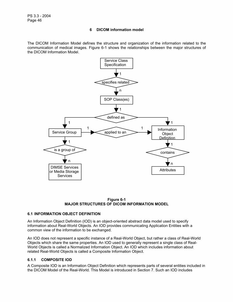
PS 3.3 - 2004 Page 46
6 DICOM information model
The DICOM Information Model defines the structure and organization of the information related to the communication of medical images. Figure 6-1 shows the relationships between the major structures of the DICOM Information Model.
InformationObject
DefinitionService Group
SOP Class(es)
Service ClassSpecification
specifies related
n
1
defined as
1
111
1
applied to an
is a group of
1
contains
1
nn
AttributesDIMSE Services
or Media StorageServices
Figure 6-1 MAJOR STRUCTURES OF DICOM INFORMATION MODEL
6.1 INFORMATION OBJECT DEFINITION
An Information Object Definition (IOD) is an object-oriented abstract data model used to specify information about Real-World Objects. An IOD provides communicating Application Entities with a common view of the information to be exchanged.
An IOD does not represent a specific instance of a Real-World Object, but rather a class of Real-World Objects which share the same properties. An IOD used to generally represent a single class of Real-World Objects is called a Normalized Information Object. An IOD which includes information about related Real-World Objects is called a Composite Information Object.
6.1.1 COMPOSITE IOD A Composite IOD is an Information Object Definition which represents parts of several entities included in the DICOM Model of the Real-World. This Model is introduced in Section 7. Such an IOD includes

PS 3.3 - 2004 Page 47
Attributes which are not inherent in the Real-World Object that the IOD represents but rather are inherent in related Real-World Objects.
These related Real-World Objects provide a complete context for the exchanged information. When an instance of a Composite IOD is communicated, this entire context is exchanged between Application Entities. Relationships between Composite IOD Instances shall be conveyed in this contextual information.
The Composite IODs are specified in Annex A.
6.1.2 NORMALIZED IOD A Normalized IOD is an Information Object Definition which generally represents a single entity in the DICOM Model of the Real-World.
In this Standard, strict definition of Normalized Object Definitions has not been applied. Application of strict definitions would often result in unnecessary complexity and reduced performance of implementations for several applications.
Note: An example is the Print Queue IOD. Attributes from the Basic and Referenced Print Management IODs are combined in the Print Queue IOD. This allows an SCP to provide all relevant information in a single N-Get Service Element. Otherwise several Service Elements would be required to return the attributes from individual Normalized IODs. This requires less network traffic to convey the information, thus improving system performance.
The Print Queue IOD has been classified as a Normalized IOD to allow operations by DIMSE-N Services since most devices which support the Print Queue Management SOP Class also support the Basic Print Management Meta SOP Class in which the DIMSE-N Service Elements are used. This facilitates efficient implementations of the Print Queue Management SOP Class.
When an instance of a Normalized IOD is communicated, the context for that instance is not actually exchanged. Instead, the context is provided through the use of pointers to related Normalized IOD Instances.
The Normalized IODs are specified in Annex B.
6.2 ATTRIBUTES
The Attributes of an IOD describe the properties of a Real-World Object Instance. Related Attributes are grouped into Modules which represent a higher level of semantics documented in the Module Specifications found in Annex C.
Attributes are encoded as Data Elements using the rules, the Value Representation and the Value Multiplicity concepts specified in PS 3.5. For specific Data Elements, the Value Representation and Value Multiplicity are specified in the Data Dictionary in PS 3.6.
When multiple modules containing the same Attributes(s) are included in an IOD, the Attribute shall be encoded only once into a Data Element.
6.3 ON-LINE COMMUNICATION AND MEDIA STORAGE SERVICES
For on-line communication the DIMSE Services allow a DICOM Application Entity to invoke an operation or notification across a network or a point-to-point interface. DIMSE Services are defined in PS 3.7.
For media storage interchange, Media Storage Services allow a DICOM Application Entity to invoke media storage related operations.
Note: These Media Storage Services are discussed in PS 3.10.

PS 3.3 - 2004 Page 48
6.3.1 DIMSE-C SERVICES DIMSE-C Services are services applicable only to a Composite IOD. DIMSE-C Services provide only operation services.
6.3.2 DIMSE-N SERVICES DIMSE-N Services are services applicable only to a Normalized IOD. DIMSE-N Services provide both operation and notification services.
6.4 DIMSE SERVICE GROUP
A DIMSE Service Group specifies one or more operations/notifications defined in PS 3.7 which are applicable to an IOD.
DIMSE Service Groups are defined in PS 3.4 in the specification of a Service-Object Pair Class.
6.5 SERVICE-OBJECT PAIR (SOP) CLASS
A Service-Object Pair (SOP) Class is defined by the union of an IOD and a DIMSE Service Group. The SOP Class definition contains the rules and semantics which may restrict the use of the services in the DIMSE Service Group and/or the Attributes of the IOD.
The selection of SOP Classes is used by Application Entities to establish an agreed set of capabilities to support their interaction. This negotiation is performed at association establishment time as described in PS 3.7. An extended negotiation allows Application Entities to further agree on specific options within a SOP Class.
Note: The SOP Class as defined in the DICOM Information Model is equivalent in ISO/OSI terminology to the Managed Object Class. Readers familiar with object oriented terminology will recognize the SOP Class operations (and notifications) as comprising the methods of an object class.
6.5.1 NORMALIZED AND COMPOSITE SOP CLASSES DICOM defines two types of SOP Classes, Normalized and Composite. Normalized SOP Classes are defined as the union of a Normalized IOD and a set of DIMSE-N Services. Composite SOP Classes are defined as the union of a Composite IOD and a set of DIMSE-C Services.
Note: SOP Class Specifications play a central role for defining DICOM conformance requirements. It allows DICOM Application Entities to select a well-defined application level subset of the DICOM V3.0 Standard to which they may claim conformance. See PS 3.2.
6.6 ASSOCIATION NEGOTIATION
Association establishment is the first phase of communication between peer DICOM compliant Application Entities. The Application Entities shall use association establishment to negotiate which SOP Classes can be exchanged and how this data will be encoded.
Association Negotiation is defined in PS 3.7.
6.7 SERVICE CLASS SPECIFICATION
A Service Class Specification defines a group of one or more SOP Classes related to a specific function which is to be accomplished by communicating Application Entities. A Service Class Specification also defines rules which allow implementations to state some pre-defined level of conformance to one or more SOP Classes. Applications may conform to SOP Classes as either a Service Class User (SCU) or Service Class Provider (SCP).

PS 3.3 - 2004 Page 49
Service Class Specifications are defined in PS 3.4.
Note: Such interaction between peer Application Entities work on a 'client/server model'. The SCU acts as the 'client', while the SCP acts as the 'server'. The SCU/SCP roles are determined during association establishment.
7 DICOM model of the real-world
Figures 7-1a, 7-1b and 7-3 depict the DICOM view of the Real-World which identifies the relevant Real-World Objects and their relationships within the scope of the DICOM Standard. It provides a common framework to ensure consistency between the various Information Objects defined by the DICOM Standard.
Note: The relationship between study and result is complex, involving other Real-World Objects (e.g. the interpreting physician). This Standard does not model these objects.

PS 3.3 - 2004 Page 50
Patient
Visit
Study
Study ContentNotificationmakes has
describes
includes
StudyComponents
Modality PerformedProcedure Steps
Comprisedof
Comprisedof
includes includes contains See Note
Results
contains
Report
LookupTable
StoredPrint
RadiotherapyObjects
1-n
1
0-n
1
1-n
1
1
1-n1
1
1-n
1-n
1-n
1 1 1
0-n
0-n0-n
1-n
0-n
1
0-1
0-n
Series
Frame ofReference
creates
SpatiallyDefines
Equipment
1-n 1-n 1-n
1-n
1-n
0-1
1
Curve
Overlay
0-n
Image
Ammendment
0-n
contains1
0-n
0-n
SR Document
PresentationState
0-n
Waveform
0-n
MR Spectroscopy
0-n
Raw Data
0-n
0-n
Fiducials
Registration
SpatiallyDefines
1-n
1
Figure 7-1a DICOM MODEL OF THE REAL-WORLD

PS 3.3 - 2004 Page 51
Image
Printer Image Box
Lookup Table
uses
is presented by
uses
Presentation LUT Relates tocontains
Film Box
contains
Film Session
Annotation
Contains
Relates to
Print Queue
contains
Print Job
maintains 1
0-1
1
0-n
Prints 1
1-n 0-n
1
1-n
1
0-1
0-1
1-n
1-n
1-n0-n
0-n1-n
0-n1-n
1
1-n
Overlay
Issues 0-1 1
Issues 0-1 1
Figure 7-1b DICOM MODEL OF THE REAL-WORLD - PRINT

PS 3.3 - 2004 Page 52
Patient IOD
Visit IOD
Study IOD
Basic StudyDescriptor IODreferences references
describes
references
Study ComponentIOD
Modality PerformedProc. Step IOD
Comprisedof
Comprisedof
references references references
See Note
Results IOD
references
Interpretation IOD
Image IOD
StandaloneCurve IOD
StandaloneOverlay IOD
StandaloneModality LUT IOD
Standalone VOILUT IOD
Stored Print IODSee Figure 7.2b
Radiotherapy IODsSee Figure 7.2c
1-n
1
0-n
1
1-n
1
1
1-n1
1
1-n
1-n
1-n
1 1 1
0-n 0-n
0-n0-n0-n
1-n
0-n
1
0-n
0-n
PresentationState IOD
0-n
0-n
0-n
Waveform IOD
SR DocumentIOD
0-n
0-n
Raw Data IOD
MR SpectroscopyIOD
0-n
0-n
FiducialsIOD
RegistrationIOD
Figure 7-2a DICOM INFORMATION MODEL
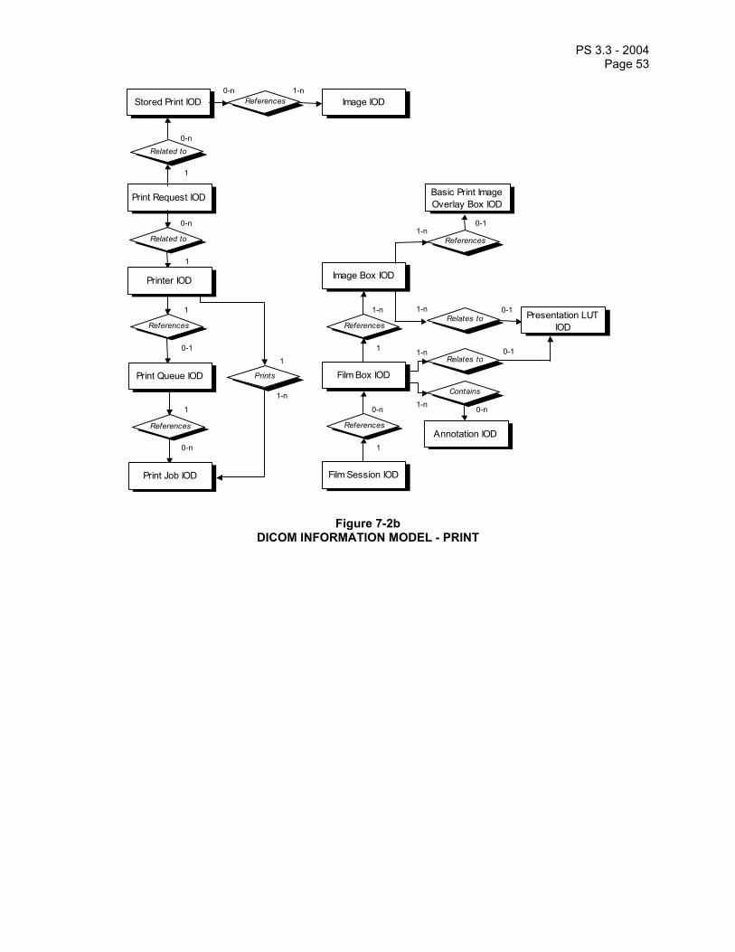
PS 3.3 - 2004 Page 53
Related to
Print Request IOD
Image IOD
0-n
1
Stored Print IOD
Related to
Printer IOD
0-n
1
References 0-n 1-n
Image Box IOD
Basic Print Image Overlay Box IOD
References
Relates toReferences
Film Box IOD
References
Film Session IOD
Annotation IOD
Contains
Relates to
Print Queue IOD
References
Print Job IOD
References 1
0-1
1
0-n
Prints 1
1-n 0-n
1
1-n
1
0-1
0-1
1-n
1-n
1-n0-n
0-11-n
Presentation LUT IOD
Figure 7-2b DICOM INFORMATION MODEL - PRINT

PS 3.3 - 2004 Page 54
Study IOD
references
Image IODRT Structure SetIOD
1
0-n0-n0-n0-n
RT Image IOD RT Dose IOD RT Plan IOD
0-n
references references
references
references
references
0-n 0-n 0-n 0-1 0-n 0-n
0-1 0-n0-n
0-n 11
1
1
0-n
0-n
RT TreatmentRecord IOD
references
1
0-n
references
0-n
1references
10-n
Figure 7-2c DICOM INFORMATION MODEL - RADIOTHERAPY

PS 3.3 - 2004 Page 55
PatientVisit
Imaging ServiceRequest
has
includeshas
occursduring
1
0-n
1
1
0-n
11
0-n
1-n
0-n
has has
1
ServiceEpisodeIs context
for
0-n
RequestedProcedure
0-n
0-n
11-n
ProcedureTypespecifies
0-n
1
specifies
to beperformedaccording
to
1
ProcedurePlan
1
iscomposed
ofresults
in
1-n
ScheduledProcedure Step
includes
1
1
specifies
1
ProtocolCode
1-n
1-n
Mod. PerformedProcedure Step
1
resultsin
belongsto
0-n
Seriesdescribes0-n 1
0-n0-n
0-n0-n
Figure 7-3. MODEL OF THE REAL WORLD FOR THE PURPOSE OF MODALITY-IS INTERFACE
7.1 DICOM INFORMATION MODEL
The DICOM Information Model is derived from the DICOM Model of the Real-World. The DICOM Information Model presented by Figures 7-2a, 7-2b and 7-2c identify the various IODs specified by this Standard and their relationships. There is not always a one-to-one correspondence between DICOM Information Object Definitions and Real-World Objects. For example a Composite IOD contains Attributes of multiple real-world objects such as series, equipment, frame of reference, study and patient.
The entities in Figures 7-2a, 7-2b and 7-2c correspond to IODs defined in Annexes A through C.
7.2 ORGANIZATION OF ANNEXES A, B AND C
Annex A defines Composite IOD's (e.g. Images, Curves, Overlays) acquired on a number of Modalities (e.g. CT, MR, NM, US, CR, Secondary Capture). These Composite IOD's reference Modules found in Annex C.
Annex B defines Normalized IODs (e.g. Patient, Study, Results, Film Session, Print Job) for a number of Service Classes specified in PS 3.4. These Normalized IODs reference Module definitions found in Annex C.
7.3 EXTENSION OF THE DICOM MODEL OF THE REAL-WORLD
For the purpose of the Basic Worklist Management Service Class and the Modality Performed Procedure Step SOP Classes an enhancement of the original DICOM Model of the Real-World is made, as depicted in Figure 7-3.

PS 3.3 - 2004 Page 56
The PS 3.17 Annex entitled Integration of Modality Worklist and Modality Performed Procedure Step in the Original DICOM Standard discusses the relationship of this extension to the original DICOM model of the real world.
Figure 7-3 is an abstract description of the real world objects invoked in the Modality-IS Interface. It is not to be seen as a database scheme for an implementation.
Note: The real world model depicted in Figure 7.3 is influenced by the ISIS (Information System - Imaging System) Model. The ISIS Model is being developed by the DICOM Committee, the College of American Pathologists Image Exchange Committee (CAP-IEC), CEN/TC251/WG4/PT4-020: Modality-Information System Interface Project Team, and Health Level Seven (HL7) as the Real World Model for the domain of the Information System - Imaging System interface. The ISIS model is a common mapping of CEN/TC251/WG3/PT-022, CEN/TC251/WG4/PT-020, HL7, CAP-IEC, and ACR-NEMA DICOM Real-World-Models. The semantics of the objects and their attributes in this Standard are described in the ISIS model. This supplement uses only the subset of the ISIS Model that contains objects relevant to the Worklist. The ISIS Model ensures consistency with PT-022, CAP-IEC, and HL7.
7.3.1 Definition of the Extensions of the DICOM Real-World Model 7.3.1.1 PATIENT A Patient is a person receiving, or registered to receive, healthcare services.
7.3.1.2 SERVICE EPISODE A Service Episode is a collection of events, aggregated during an interval bounded by start and stop times (e.g. an outpatient visit or a hospitalization). The definition of the start time, stop time, and included events of a Service Episode is entirely arbitrary. A Service Episode is the context in which the treatment or management of an arbitrary subset of a Patient’s medical conditions occurs. In the context of imaging services, a Service Episode may involve one or more Healthcare Organizations (administrative entities that authorize Healthcare Providers to provide services within their legal administrative domain, e.g. hospitals, private physician’s offices, multispecialty clinics, nursing homes). A subset of Service Episode, the Facility Episode, is the collection of events that fall under the accountability of a particular Healthcare Organization. A Service Episode identifies the Certified Health Care Providers who have been delegated responsibility by one or more Healthcare Organizations to provide healthcare services to the Patient. One or more Certified Healthcare Providers (Organizations or individual persons, e.g. physician group practices, individual physicians, technologists, nurses) may be accountable for the healthcare services provided in a Service Episode. The Certified Health Care Providers are accountable to one or more Healthcare Organizations and to the Patient for the outcomes of the services provided. A Service Episode may be associated with one or more physical locations (e.g. different rooms, departments, buildings, or cities). One or more DICOM Visits may be associated with a Service Episode.
Notes: 1. The Service Episode is defined both in the ISIS model and in this extension of the DICOM model of the real world, to ensure consistency with PT3-022, CAP-IEC and HL7. The DICOM Visit is a part of the Service Episode. The Service Episode describes several administrative aspects of healthcare, while the DICOM Visit is limited to the description of one visit of a Patient to a facility.
2. In the context of the Modality Worklist SOP Class, only the DICOM Visit is of relevance, the Service Episode Modules are not defined.
7.3.1.3 IMAGING SERVICE REQUEST An Imaging Service Request is a set of one or more Requested Procedures selected from a list of Procedure Types. An Imaging Service Request is submitted by one authorized imaging service requester to one authorized imaging service provider in the context of one Service Episode. An Imaging Service Request includes pertinent specific and general information. Each instance of an Imaging Service Request carries the information common to one or more Requested Procedures requested at the same moment. An Imaging Service Request may be associated with one or more DICOM Visits. The existence of an Imaging Service Request will typically result in the creation of one or more Imaging Service Reports and the distribution of Imaging Service Reports to one or more destinations.

PS 3.3 - 2004 Page 57
In the context of the Modality Worklist the information provided by the Imaging Service Request aims at performing one or more imaging procedures, i.e. at acquiring new images. In the context of the General Purpose Worklist the information provided by the Imaging Service Request supports a more general kind of request, e.g. reporting, requesting an image processing procedure on an existing examination, etc.
7.3.1.4 PROCEDURE TYPE A Procedure Type identifies a class of procedures. In the context of imaging services, a Procedure Type is an item in a catalog of imaging procedures that can be requested and reported upon in an imaging service facility. An instance of a Procedure Type typically has a name and one or more other identifiers. A Procedure Type is associated with one or more Procedure Plans.
Note: The information content of this entity relates to the general identification of a Procedure Type rather than to its decomposition into the protocol(s) required to perform a specific instance of a Requested Procedure for a particular Patient.
7.3.1.5 REQUESTED PROCEDURE A Requested Procedure is an instance of a Procedure of a given Procedure Type. An instance of a Requested Procedure includes all of the items of information that are specified by an instance of a Procedure Plan that is selected for the Requested Procedure by the imaging service provider. This Procedure Plan is defined by the imaging service provider on the basis of the Procedure Plan templates associated with the considered Procedure Type. An Imaging Service Request may include requests for several different Requested Procedures. The purpose of this entity is to establish the association between Imaging Service Requests and Procedure Types, to convey the information that belongs to this association and to establish the relationships between Requested Procedures and the other entities that are needed to describe them. A single Requested Procedure of one Procedure Type is the smallest unit of service that can be requested, reported, coded and billed. Performance of one instance of a Requested Procedure is specified by exactly one Procedure Plan. A Requested Procedure leads to one or more Scheduled Procedure Steps involving Protocols as specified by a Procedure Plan. A Requested Procedure may be associated with one or more DICOM Visits. A Requested Procedure may involve one or more pieces of equipment.
7.3.1.6 SCHEDULED PROCEDURE STEP A Modality Scheduled Procedure Step is an arbitrarily defined scheduled unit of service, that is specified by the Procedure Plan for a Requested Procedure. A Modality Scheduled Procedure Step prescribes Protocol which may be identified by one or more protocol codes. A Modality Scheduled Procedure Step involves equipment (e.g. imaging Modality equipment, anesthesia equipment, surgical equipment, transportation equipment), human resources, consumable supplies, location, and time (e.g. start time, stop time, duration). While in the context of imaging services the scheduling of a Modality Scheduled Procedure Step might include only a general designation of imaging Modality that could be satisfied by multiple pieces of the same equipment type, the performance of one instance of a Modality Scheduled Procedure Step involves one and only one piece of imaging Modality equipment.
The performance of a Modality Scheduled Procedure Step may result in the creation of zero or more Modality Performed Procedure Step instances.
Notes: 1. The Procedure Step entity is provided to support management of the logistical aspects of procedures (e.g. materials management, human resources, scheduling). The full definition of the contents of Procedure Steps and protocols according to which they are performed is implementation dependent and is beyond the scope of this Standard.
2. A Modality Scheduled Procedure Step may contribute to more than one Requested Procedure (e.g. a Modality Scheduled Procedure Step requiring an intravenous iodine contrast injection might be shared by an intravenous pyelogram and a CT examination). However, for billing purposes an instance of a Modality Scheduled Procedure Step is typically considered to be a part of only one Requested Procedure.

PS 3.3 - 2004 Page 58
7.3.1.7 PROCEDURE PLAN A Procedure Plan is a specification that defines the set of Protocols that must be done in order to perform the Scheduled Procedure Steps of a Requested Procedure. Each Scheduled Procedure Step is preformed according to a single Protcol which may be identified by one or more Protocol Codes. The Protocols actually performed during a Procedure Step may differ from those prescribed in the related Procedure Plan. Audit of actually performed Protocols versus the prescribed Procedure Plan is an important element of quality control, but is not specified by this Standard.
Note: The fact that Protocols Codes are in a given order in a Procedure Plan is not evident in Figure 7.3. However, the order of Protocols is represented at the syntax level (i.e. as the sequence of items present in the Protocol Code Sequence (0040,0008)).
7.3.1.8 PROTOCOL A Protocol is a specification of actions prescribed by a Procedure Plan to perform a specific Procedure Step. A Scheduled Procedure Step contains only one Protocol which may be conveyed by one or more Protocol Codes. Typically, the code or codes identifying a Protocol instance would be selected from a catalog of protocols. Multiple Protocols may not exist in one Scheduled Procedure Step.
7.3.1.9 MODALITY PERFORMED PROCEDURE STEP A Performed Procedure Step is an arbitrarily defined unit of service that has actually been performed (not just scheduled). Logically it corresponds to a Scheduled Procedure Step, but real-world conditions may dictate that what is actually performed does not correspond exactly with what was requested or scheduled.
Note: For example, two or more Scheduled Procedure Steps, Requested Procedures or Imaging Service Requests may have been generated by different Referring Physicians but may be satisfied be a single Performed Procedure Step at the discretion of a Performing Physician or Operator. Alternatively, a single Scheduled Procedure Step may need to be satisfied by multiple Performed Procedure Steps on different types or instances of equipment, due to clinical need or failure conditions, or over extended periods of time.
It contains information describing the type of procedure actually performed. This information is represented by the Performed Protocol that may be defined by one or more Protocol Codes.
A Requested Procedure results in the creation of zero or more Performed Procedure Steps.
A Scheduled Procedure Step results in the creation of zero or more Performed Procedure Steps.
The Performed Procedure Step contains information about it’s state (e.g. in progress, discontinued or completed).
A Modality Performed Procedure Step is a Performed Procedure Step that results from the acquisition of images from a Patient or other Imaging Subject on a Modality.
It contains information describing the performance of a step of an imaging procedure, including data about the performance of the procedure itself, radiation dose values to which the patient has been exposed if ionizing radiation is in use, and data for billing and material management.
The Modality Performed Procedure Step contains references to zero or more Series of Images and other Composite SOP Instances that may be created as part of the procedure step. A particular Series is part of only one Modality Performed Procedure Step.
7.3.1.10 GENERAL PURPOSE SCHEDULED PROCEDURE STEP A General Purpose Scheduled Procedure Step is an arbitrarily defined scheduled unit of service, that is specified by the Procedure Plans of one or more Requested Procedures. A General Purpose Scheduled Procedure Step prescribes one Workitem that describes the procedure step to be performed. A General

PS 3.3 - 2004 Page 59
Purpose Scheduled Procedure Step involves applications, human resources, location, and time resources (e.g. start time, stop time, duration).
Notes: 1. In this section, application is the generic term used to designate software applications and pieces of devices.
2. The status of a general Purpose Scheduled Procedure Step must not be confused with the status of the Requested Procedure or Imaging Service Request to which it belongs. One General Purpose Scheduled Procedure Step may be completed, but that does not imply that also the related Requested Procedure has reached its completion.
A General Purpose Scheduled Procedure Step contains references to Composite SOP Instances or Performed Procedure Steps, which denote the information to be used for the performance of the General Purpose Scheduled Procedure Step.
7.3.1.11 GENERAL PURPOSE PERFORMED PROCEDURE STEP A general Purpose Performed Procedure step is an arbitrarily defined unit of service that has actually been performed ( not just scheduled ). Normally it corresponds to one General Purpose Scheduled Procedure step, but real-world conditions may dictate that what is actually performed does not correspond exactly with what was requested or scheduled.
Note: For example, two or more General Purpose Scheduled Procedure Steps, Requested Procedures or Imaging Service Requests may have been generated by different Referring Physicians but may be satisfied by a single General Purpose Performed Procedure Step at the discretion of a Performing Physician or Operator. Alternatively, a single General Purpose Scheduled Procedure step may need to be satisfied by multiple General Purpose Performed Procedure Steps on different types or instances of equipment, due to clinical need or failure conditions, or over extended periods of time.
It contains information describing the type of procedure actually performed.
A Requested Procedure results in the creation of zero or more General Purpose Performed Procedure Steps.
A General Purpose Scheduled Procedure Step results in the creation of zero or more General Purpose Performed Procedure Steps.
The General Purpose Performed Procedure Step contains information about its state.
It contains information describing the performance of the general purpose procedure step of a procedure.
The General Purpose Performed Procedure step contains references to zero or more Composite SOP Instances that have been created as part of the procedure step.
7.3.1.12 WORKITEM A Workitem is one of the tasks prescribed by a Procedure Plan to perform an instance of a Requested Procedure. Each General Purpose Scheduled Procedure Step will contain exactly one Workitem. The code identifying a Workitem instance would be selected from a catalog of workitem types, for example with the value of Image Processing or Interpretation.
7.4 EXTENSION OF THE DICOM MODEL OF THE REAL-WORLD FOR THE GENERAL PURPOSE WORKLIST
For the purpose of the General Purpose Worklist SOP Class in the Worklist Management Service Class an extension of the DICOM Model of the Real-World is made, as depicted in Figures 7.4.a and 7.4.b.
This subset of the real-world model covers the requirements for the General Purpose Worklist SOP Class in the Worklist Management Service Class.

PS 3.3 - 2004 Page 60
Figures 7.4.a and 7.4.b are an abstract description of the real world objects involved in Workflow Management.
PatientVisit
Imaging ServiceRequest
has
includeshas
occursduring
1
0-n
1
1
0-n
11
0-n
1-n
0-n
has has
1
ServiceEpisode
Is contextfor
0-n
RequestedProcedure
0-n
0-n
11-n
ProcedureTypespecifies
0-n
1-n
specifies
to beperformedaccording
to
1
ProcedurePlan
1is
composedof
resultsin
0-n
General PurposeScheduled Procedure
Step
includes
1-n
1
specifies
1
Workitem
0-n
1
General Purpose PerformedProcedure Step
1
resultsin
creates
0-n
Seriesdescribes1 1
0-n0-n
0-n0-n
Figure 7.4.a Model of the real world for the purpose of General Purpose Worklist interface

PS 3.3 - 2004 Page 61
PerformedProcedure Step
General PurposePerformed
Procedure Step
General PurposeScheduled
Procedure StepResults
in
0-n
CompositeObject Is input
for
Is relevantfor
Is input for
0-m
0-n
0-n
0-n 0-m
0-m
0-m
Creates
Series
CompositeObject
Contains
0-n
1
1
0-n
Figure 7.4.b Model of the real world for the purpose of General Purpose Worklist interface

PS 3.3 - 2004 Page 62
7.5 ORGANIZING LARGE SETS OF INFORMATION
For the purpose of accommodating large sets of frames in Multi-frame Image SOP Instances the Real-World Entity Relationship Diagram has been extended to describe the relationships of these instances: Concatenation (see Section 7.5.1) and Dimension Organization (see Section 7.5.2). Figure 7-5.1 depicts the additions to Figure 7-2.
Patient
isthe subject
of
1
1
Study
1,n
Series
contains
Spatially ortemporally
defines
EquipmentFrame of Reference
creates
111,n
0,n
1,n
contains
1
Concatenation
0,n
contains
1
Image(Multi-frame)
1,n
DimensionOrganization
0,n
contains
1
Specifiesorganization
of
1 1,n
1
0,n
contains
Figure 7.5-1 EXTENSION OF THE REAL-WORLD MODEL WITH CONCATENATIONS AND DIMENSIONS
7.5.1 CONCATENATION For implementation specific reasons (such as practical limits on the maximum size of an individual SOP Instance) the content of a multi-frame image may need to be split into more than one SOP Instance. These SOP Instances together form a Concatenation, which is a group of SOP Instances within a Series that is uniquely identified by the Concatenation UID (0020,9133).
7.5.2 DIMENSION ORGANIZATION The Dimension Organization contains a set of dimensions. A dimension is a set of attributes which change on a per-frame basis in a manner which is known before the image is acquired, which are defined by the generating application and which are especially intended for presentation. Other attributes may

PS 3.3 - 2004 Page 63
also change on a per-frame basis but if they are not present in the Dimension Organization, they are not considered significant as a dimension for organizational purposes.
Receiving applications can use the order of dimensions for guidance when presenting images. The first item of the Dimension Index Sequence shall be the slowest varying index.
Note: See Multi-frame Dimension Module section (C.7.6.17) for an example.
7.6 EXTENSION OF THE DICOM MODEL OF THE REAL WORLD FOR CLINICAL TRIALS
The DICOM Model of the Real World is extended for Clinical Trials with the addition of several objects whose relationships to each other and existing DICOM Real World objects are shown in Figure 7.6-1.
Attributes of the Clinical Trial Sponsor, Clinical Trial Protocol, Clinical Trial Subject, and Clinical Trial Site objects are represented in the Clinical Trial Subject Module within the Patient IOD. Attributes of the Clinical Trial Time Point object are represented in the Clinical Trial Study Module within the Study IOD. The Clinical Trial Coordinating Center attribute is represented in the Clinical Trial Series Module within Image IODs.

PS 3.3 - 2004 Page 64
Clinical Trial Sponsor
Clinical Trial Protocol
Clinical Trial Subject
Patient
Study
Series
Clinical Trial Site
Clincal Trial Coord. Center
conducts
involves
identified as
has
contains
receives located at
1-n
1
1
1-n
1-n
1-n
1-n 1
1
1
0-1 1-n
Clinical Trial Time Point contains
1-n 0-1 1-n
1
Figure 7.6-1 – DICOM MODEL OF THE REAL WORLD – CLINICAL TRIALS
7.6.1 Clinical Trial Information Entities For the purpose of Clinical Trial Information, an extension of the DICOM Model of the Real World is made, as depicted in Figure 7.6-1.
7.6.1.1 Clinical Trial Sponsor A Clinical Trial Sponsor identifies the agency, group, or institution responsible for conducting the clinical trial and for assigning a Protocol Identifier.
7.6.1.2 Clinical Trial Protocol A Clinical Trial Protocol identifies the investigational Protocol in which the Subject has been enrolled. The Protocol has a Protocol Identifier and Protocol Name.
7.6.1.3 Clinical Trial Subject A Clinical Trial Subject identifies the Patient who is enrolled as a Subject in the investigational Protocol.
7.6.1.4 Clinical Trial Site A Clinical Trial Site identifies the location or institution at which the Subject is treated or evaluated and which is responsible for submitting clinical trial data. Images and/or clinical trial data may be collected for a given Subject at alternate institutions, e.g. follow-up scans at a satellite imaging center, but the Clinical

PS 3.3 - 2004 Page 65
Trial Site represents the primary location for Patient management and data submission in the context of a clinical trial.
7.6.1.5 Clinical Trial Time Point The Clinical Trial Time Point identifies an imaging Study within the context of an investigational protocol. A Time Point defines a set of studies that are grouped together as a clinical time point or submission in a clinical trial.
7.6.1.6 Clinical Trial Coordinating Center The Clinical Trial Coordinating Center identifies the institution responsible for coordinating the collection, management, processing, and/or analysis of images and associated data for Subjects enrolled in a clinical trial. Within a given Clinical Trial Protocol, there may be multiple Clinical Trial Coordinating Centers, each handling different aspects of the clinical data submitted by the Clinical Trial Sites.

PS 3.3 - 2004 Page 66
8 Encoding of Coded Entry Data
The primary method of incorporating coded entry data in DICOM IODs is the Code Sequence Attribute. Code Sequence Attributes are encoded as a Sequence of Items using a macro which is described in this section. These Attributes typically include the string "Code Sequence" in the Attribute Name. Their purpose is to encode terms by using codes from coding schemes.
Note: In this Standard, Code Sequence Attributes are defined for a variety of concepts, for example: Primary Anatomic Structure Sequence (0008,2228) and other Attributes to describe anatomy; and Interventional Drug Code Sequence (0018,0029), to document administration of drugs that have special significance in Imaging Procedures.
Each Item of a Code Sequence Attribute contains the triplet of Coding Scheme Designator, the Code Value, and Code Meaning. Other optional and conditional attributes may also be present.
For any particular Code Sequence Attributes, the range of codes that may be used for that attribute (the Value Set) may be suggested or constrained by specification of a Context Group. The Module or Template in which the attribute is used will specify whether or not the context group is baseline or defined. A Baseline Context Group lists codes for terms which are suggested and may be used, but are not required to be used. A Defined Context Group lists codes for terms which shall be used if the term is used.
Context Groups are defined in a Mapping Resource, such as the DICOM Content Mapping Resource (DCMR) specified in PS 3.16. Context Groups consist of lists of contextually related coded concepts, including the Code Value (0008,0100) and Coding Scheme Designator (0008,0102). Each concept is unqiue within the Context Group and identified by its Code Value (0008,0100) and Coding Scheme Deisgnator (0008,0102). The Context Group specification identifies whether it is extensible, i.e., whether it may be modified in an Application to use additional terms (see PS 3.16). Whether a Context Group is used as a Baseline or Defined Context Group is defined not in the mapping resource, but rather in the Template or Module in which the Code Sequence Attribute is used.
Context Groups are identified by labels referred to as Context Group Identifiers (CID).
8.1 CODE VALUE
The Code Value (0008,0100) is an identifier that is unambiguous within the Coding Scheme denoted by Coding Scheme Designator (0008,0102) and Coding Scheme Version (0008,0103).
Note: The Code Value is typically not a natural language string, e.g. “T-04000”.
8.2 CODING SCHEME DESIGNATOR AND CODING SCHEME VERSION
The attribute Coding Scheme Designator (0008,0102) identifies the coding scheme in which the code for a term is defined. Standard coding scheme designators used in DICOM information interchange are listed in PS 3.16. Other coding scheme designators, for both private and public coding schemes, may be used. Further identification of the coding scheme designators used in a SOP Instance may be provided in the Coding Scheme Identification Sequence (0008,0110) (see Section C.12).
Notes: 1. Typical coding schemes used in DICOM include “DCM” for DICOM defined codes, “SNM3” for SNOMED version 3, “SRT” for SNOMED-RT, and “LN” for LOINC.
2. Coding scheme designators beginning with “99” and the coding scheme designator “L” are defined in HL7 V2 to be private or local coding schemes.

PS 3.3 - 2004 Page 67
3. Most IODs that define the use of coded terms provide for the use of private codes and coding schemes through replacement of Baseline Context Groups or extension of Defined Context Groups. Systems supporting such private code use must provide a mechanism for the configuration of sets of Coding Scheme Designator, Code Value, and Code Meaning to support interoperation of the private codes with other systems.
4. It is highly recommended that local or non-standard coding schemes be identified in the Coding Scheme Identification Sequence.
The attribute Coding Scheme Version (0008,0103) may be used to identify the version of a coding scheme if necessary to resolve ambiguity in the Code Value (0008,0100) or Code Meaning (0008,0104), or if the Code Value does not appear in all versions of the Coding Scheme identified by the Coding Scheme Designator.
In previous editions of the DICOM Standard, a provisional Coding Scheme Identifier of "99SDM" was used for SNOMED codes that were used in DICOM.
Consequently, when a Coding Scheme Designator (0008,0102) of “99SDM” is encountered, it shall be treated as equivalent to “SNM3” for the purpose of interpreting Code Value (0008,0100).
A Coding Scheme Designator (0008,0102) of “99SDM” or “SNM3” is defined to identify the SNOMED Version 3 Coding Scheme unambiguously, hence the condition for inclusion of Coding Scheme Version (0008,0103) is explicitly not satisfied.
8.3 CODE MEANING
The Code Meaning (0008,0104) is text which has meaning to a human and which conveys the meaning of the term defined by the combination of Code Value and Coding Scheme Designator. Though such a meaning can be “looked up” in the dictionary for the coding scheme, it is encoded for the convenience of applications that do not have access to such a dictionary.
It should be noted that for a particular Coding Scheme Designator (0008,0102) and Code Value (0008,0100), several alternative values for Code Meaning (0008,0104) may be defined. These may be synonyms in the same language or translations of the Coding Scheme into other languages. Hence the value of Code Meaning (0008,0104) shall never be used as a key, index or decision value, rather the combination of Coding Scheme Designator (0008,0102) and Code Value (0008,0100) may be used. Code Meaning (0008,0104) is a purely annotative, descriptive Attribute.
This does not imply that Code Meaning (0008,0104) can be filled with arbitrary free text. Available values from the Coding Scheme or translation in the chosen language shall be used.
8.4 MAPPING RESOURCE
The value of Mapping Resource (0008,0105) denotes the message/terminology Mapping Resource that specifies the Context Group that specifies the Value Set. The Defined Terms for the value of Mapping Resource (0008,0105) shall be:
“DCMR”= “DICOM Content Mapping Resource”, "SDM"= "SNOMED DICOM Microglossary" (Retired).
PS 3.16 specifies the DICOM Content Mapping Resource (DCMR).
Note: Unless otherwise specified, the DCMR is the source of all Context Groups and Templates specified in this Standard.

PS 3.3 - 2004 Page 68
8.5 CONTEXT GROUP VERSION
Context Group Version (0008,0106) conveys the version (as a datetime value) of the Context Group identified by Context Identifier (0008,010F).
8.6 CONTEXT IDENTIFIER
The value of Context Identifier (0008,010F) identifies the Context Group defined by Mapping Resource (0008,0105) from which the values of Code Value (0008,0100) and Code Meaning (0008,0104) were selected , or to which the Code Value (0008,0100) and Code Meaning (0008,0104) have been added as a private Context Group extension (see Section 8.7) .
Note: Privately defined Context Groups are not identified by Context Identifier and Mapping Resource.
8.7 CONTEXT GROUP EXTENSIONS
Context Group Extension Flag (0008,010B) may be used to designate a Code Value/Code Meaning pair as a selection from a private extension of a Context Group. If the Context Group Extension Flag is present, and has a value of “Y”, Context Group Extension Creator UID (0008,010D) shall be used to identify the person or organization who created the extension to the Context Group. Context Group Local Version (0008,0107) conveys an implementation-specific private version datetime of a Context Group that contains private extensions
Notes: 1. These Attributes provide the means for implementations to extend code sets conveniently, while preserving referential integrity with respect to the original Context Group Version.
2. The locally-defined (private) value of Context Group Local Version (0008,0107) typically would be a more recent date than the standard value of Context Group Version (0008,0106) specified in the standard message/terminology Mapping Resource that defines the Context Group.
8.8 STANDARD ATTRIBUTE SETS FOR CODE SEQUENCE ATTRIBUTES
Table 8.8-1 specifies the default set of Attributes encapsulated in the Items of Code Sequence Attributes. These Attributes comprise the Code Sequence Macro.
Note: The instruction “ Include ‘Code Sequence Macro’ Table 8.8-1” may be used in an Information Object Definition as a concise way to indicate that the attributes of Table 8.8-1 are included in the specification of the Attribute Set of a Sequence of items. Additional constraints on the Code Sequence Data Element (such as a Context Group that defines the value set) may be appended to the “Include ‘Code Sequence Macro’ Table 8.8-1” instruction.
The default specifications of this Section are overridden within the scope of a Sequence Item or Code Sequence Attribute or IOD by corresponding specifications defined within the scope of that Sequence Item or Code Sequence Attribute or IOD. Additional Attributes may also be specified by the instantiation of the macro.
The Basic Coded Entry Attributes fully define a Coded Entry. If it is desired to convey the list from which a code has been chosen, then the optional Enhanced Encoding Mode Attributes may also be sent.

PS 3.3 - 2004 Page 69
Table 8.8-1 Common Attribute Set for Code Sequence Attributes (Invoked as “Code Sequence Macro”)
Attribute Name Tag Type Attribute Description BASIC CODED ENTRY ATTRIBUTES
Code Value (0008,0100) 1C See Section 8.1. Required if a sequence item is present. Coding Scheme Designator
(0008,0102) 1C See Section 8.2. Required if a sequence item is present.
Coding Scheme Version
(0008,0103) 1C See Section 8.2. Required if a sequence item is present and the value of Coding Scheme Designator (0008,0102) is not sufficient to identify the Code Value (0008,0100) unambiguously.
Code Meaning (0008,0104) 1C See Section 8.3. Required if a sequence item is present. ENHANCED ENCODING MODE
Context Identifier (0008,010F) 3 See Section 8.6. Mapping Resource (0008,0105) 1C See Section 8.4. Required if Context Identifier (0008,010F)
is present. Context Group Version
(0008,0106) 1C See Section 8.5. Required if Context Identifier (0008,010F) is present.
Context Group Extension Flag
(0008,010B) 3 Indicates whether the Code Value/Coding Scheme/Code Meaning is selected from a private extension of the Context Group identified in Context Identifier (0008,010F). See Section 8.7 of this Part. Enumerated Values: “Y”, ”N”
Context Group Local Version
(0008,0107) 1C See Section 8.7. Required if the value of Context Group Extension Flag (0008,010B) is "Y". .
Context Group Extension Creator UID
(0008,010D) 1C Identifies the person or organization who created an extension to the Context Group. See Section 8.7. Required if the value of Context Group Extension Flag (0008,010B) is "Y".
9 TEMPLATE IDENTIFICATION MACRO
A Template for SR Documents defines a set of constraints on the relationships and content (Value Types, Codes, etc.) of Content Items that reference such a Template. Specific Templates for SR Documents are defined either by the DICOM Standard or by users of the Standard for particular purposes.
The presence of a referenced Template reflects that the referenced Template was used in the creation of the associated Content Item. The use by the SR Storage SCP of Templates is beyond the scope of the DICOM Standard. Usage of Templates for SR Documents may improve comparability of essential data, facilitate data-entry and revisions, enable automatic processing and simplify presentation of information to the user.

PS 3.3 - 2004 Page 70
Table 9-1 specifies the set of Attributes that identify Templates. These Attributes comprise the Template Macro. Attribute Descriptions in Table 9-1 refer to similar attributes of the Code Sequence Macro in Section 8.8 of this Part.
Table 9-1 Template Identification Macro Attributes Description
Attribute Name Tag Type Attribute Description Template Identifier (0040,DB00) 1 Template identifier. Mapping Resource (0008,0105) 1 Mapping Resource that defines the template. See Section
8.4.
10 MISCELLANEOUS MACROS
10.1 PERSON IDENTIFICATION MACRO
This Macro may be invoked to specify a coded representation of a person such as a healthcare worker, and the organization to which they are responsible.
Notes: 1. This macro is typically invoked within a Sequence Item used to identify an individual such as a physician or a device operator.
2. The free-text name of the individual is not included in this Macro since there are already widely used specific Attributes to hold such values.
3. No Baseline, Defined or Enumerated Context Groups are defined nor is any particular coding scheme specified. In practice, workers are usually identified by using a locally or nationally specific coding scheme. For example, a local Coding Scheme Designator might be used and the individual’s internal hospital ID number user in Code Value.
4. The organization is specified by either a coded sequence or a free text name but not both.
Table 10-1 Person Identification Macro Attributes Description
Attribute Name Tag Type Attribute Description Person Identification Code Sequence
(0040,1101) 1 A coded entry which identifies a person. The Code Meaning attribute, though it will be encoded with a VR of LO, may be encoded according to the rules of the PN VR (e.g. caret ‘^’ delimiters shall separate name components), except that a single component (i.e. the whole name unseparated by caret delimiters) is not permitted. Name component groups for use with multi-byte character sets are permitted, as long as they fit within the 64 characters (the length of the LO VR). One or more Items may be permitted in this Sequence.
>Include ‘Code Sequence Macro’ Table 8.8-1
No Baseline Context ID is defined.
Person's Address (0040,1102) 3 Person's mailing address Person's Telephone Numbers
(0040,1103) 3 Person's telephone number(s)
Institution Name (0008,0080) 1C Institution or organization to which the identified individual is

PS 3.3 - 2004 Page 71
responsible or accountable. Shall not be present if Institution Code Sequence (0008,0082) is present.
Institution Address (0008,0081) 3 Mailing address of the institution or organization to which the identified individual is responsible or accountable.
Institution Code Sequence
(0008,0082) 1C Institution or organization to which the identified individual is responsible or accountable. Shall not be present if Institution Name (0008,0080) is present. Only a single Item shall be permitted in this Sequence.
>Include ‘Code Sequence Macro’ Table 8.8-1
No Baseline Context ID is defined.
10.2 CONTENT ITEM MACRO
A Content Item is a flexible means of encoding attribute identifiers and attribute values using the Code Sequence Macro (see Section 8) for coded terminology defined by a coding scheme. The Content Item provides a name-value pair, i.e., a Concept Name, encoded as a Code Sequence, and a Concept Value. The Concept Value may be encoded by any of a set of generic Attributes, as specified by a Value Type, including text, personal name, numeric, and coded concept (Code Sequence) values.
Note: Comparing a Content Item to a native DICOM Data Element, the Concept Name Code Sequence corresponds to the Data Element Tag and Attribute Name, the Value Type to the Value Representation, and the Concept Value to the Data Element Value Field. See PS3.5.
Specific uses of the Content Item may invoke the Content Item Macro defined in this Section, the Document Content Macro of Section C.17.3, or another similar construct. An invocation of the Content Item Macro may constrain the allowed values of Value Type (0040,A040).
Note: The NUMERIC Value Type of this Macro differs from the NUM Value Type defined in Section C.17.3, since the encoding of the Concept Value is different.
See Section 5.4 for the meaning of the Type column in this Macro when applied to Normalized IODs.
Table 10-2 Content Item Macro Attributes Description
Attribute Name Tag Type Attribute Description Value Type (0040,A040) 1 The type of the value encoded in this name-value Item.
Defined Terms: DATETIME DATE TIME PNAME UIDREF TEXT CODE NUMERIC
Concept Name Code Sequence
(0040,A043) 1 Coded concept name of this name-value Item.
>Include ‘Code Sequence Macro’ Table 8.8-1
No Baseline Context ID is defined.
DateTime (0040,A120) 1C Datetime value for this name-value Item.
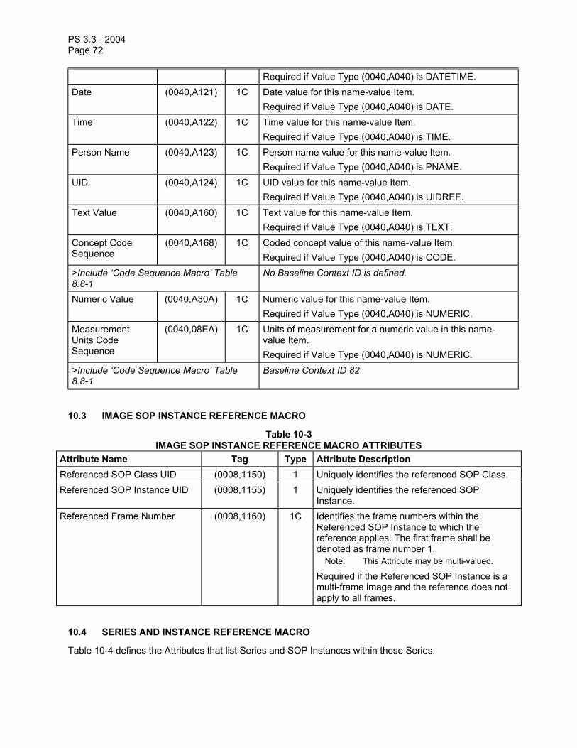
PS 3.3 - 2004 Page 72
Required if Value Type (0040,A040) is DATETIME. Date (0040,A121) 1C Date value for this name-value Item.
Required if Value Type (0040,A040) is DATE. Time (0040,A122) 1C Time value for this name-value Item.
Required if Value Type (0040,A040) is TIME. Person Name (0040,A123) 1C Person name value for this name-value Item.
Required if Value Type (0040,A040) is PNAME. UID (0040,A124) 1C UID value for this name-value Item.
Required if Value Type (0040,A040) is UIDREF. Text Value (0040,A160) 1C Text value for this name-value Item.
Required if Value Type (0040,A040) is TEXT. Concept Code Sequence
(0040,A168) 1C Coded concept value of this name-value Item. Required if Value Type (0040,A040) is CODE.
>Include ‘Code Sequence Macro’ Table 8.8-1
No Baseline Context ID is defined.
Numeric Value (0040,A30A) 1C Numeric value for this name-value Item. Required if Value Type (0040,A040) is NUMERIC.
Measurement Units Code Sequence
(0040,08EA) 1C Units of measurement for a numeric value in this name-value Item. Required if Value Type (0040,A040) is NUMERIC.
>Include ‘Code Sequence Macro’ Table 8.8-1
Baseline Context ID 82
10.3 IMAGE SOP INSTANCE REFERENCE MACRO
Table 10-3 IMAGE SOP INSTANCE REFERENCE MACRO ATTRIBUTES
Attribute Name Tag Type Attribute Description Referenced SOP Class UID (0008,1150) 1 Uniquely identifies the referenced SOP Class. Referenced SOP Instance UID (0008,1155) 1 Uniquely identifies the referenced SOP
Instance. Referenced Frame Number (0008,1160) 1C Identifies the frame numbers within the
Referenced SOP Instance to which the reference applies. The first frame shall be denoted as frame number 1.
Note: This Attribute may be multi-valued.
Required if the Referenced SOP Instance is a multi-frame image and the reference does not apply to all frames.
10.4 SERIES AND INSTANCE REFERENCE MACRO
Table 10-4 defines the Attributes that list Series and SOP Instances within those Series.

PS 3.3 - 2004 Page 73
Table 10-4 SERIES AND INSTANCE REFERENCE MACRO ATTRIBUTES
Attribute Name Tag Type Attribute Description Referenced Series Sequence (0008,1115) 1 Sequence of Items each of which includes
the Attributes of one Series. One or more Items shall be present.
>Series Instance UID (0020,000E) 1 Unique identifier of the Series containing the referenced Instances.
>Referenced Instance Sequence (0008,114A) 1 Sequence of Items each providing a reference to an Instance that is part of the Series defined by Series Instance UID (0020,000E) in the enclosing Item. One or more Items shall be present.
>>Referenced SOP Class UID (0008,1150) 1 Uniquely identifies the referenced SOP Class.
>>Referenced SOP Instance UID (0008,1155) 1 Uniquely identifies the referenced SOP Instance.
10.5 GENERAL ANATOMY MACROS
Tables 10-5 through 10-7 describe the attributes for identifying the general region of the patient anatomy examined using coded terminology, as well as the principal structure(s) within that region that is the target of the current SOP Instance. The only difference between the three macros is the Type of the Anatomic Region Sequence (0008,2218) attribute. Table 10-8 describe the attributes for the coding of the principal structure only.
The invocation of these macros may specify Baseline or Defined Context IDs for the Anatomic Region Sequence (0008,2218), the Anatomic Region Modifier Sequence (0008,2220), and/or the Primary Anatomic Structure Sequence (0008,2228).
The general region of the body (e.g. the anatomic region, organ, or body cavity being examined) is identified by the Anatomic Region Sequence (0008,2218). Characteristics of the anatomic region being examined, such as sub-region (e.g. medial, lateral, superior, inferior, lobe, quadrant) and laterality (e.g. right, left, both), may be refined by the Anatomic Region Modifier Sequence (0008,2220).
Note: These Attributes allow the specification of the information encoded by the Body Part Examined (0018,0015) in the General Series Module in a more robust, consistent way.
The specific anatomic structures of interest within the image (e.g., a particular artery within the anatomic region) is identified by the Primary Anatomic Structure Sequence (0008,2228). Characteristics of the anatomic structure, such as its location (e.g. subcapsular, peripheral, central), configuration (e.g. distended, contracted), and laterality (e.g. right, left, both), and so on, may be refined by the Primary Anatomic Structure Modifier Sequence (0008,2230).
Table 10-5 GENERAL ANATOMY MANDATORY MACRO ATTRIBUTES
Attribute Name Tag Type Attribute Description Anatomic Region Sequence (0008,2218) 1 Sequence that identifies the anatomic
region of interest in this Instance (i.e. external anatomy, surface anatomy, or general region of the body). Only a single Item shall be permitted in

PS 3.3 - 2004 Page 74
this sequence. >Include ‘Code Sequence Macro’ Table 8.8-1 Context ID may be defined in the macro
invocation. >Anatomic Region Modifier Sequence
(0008,2220) 3 Sequence of Items that modifies the anatomic region of interest of this Instance One or more Items may be included in this Sequence.
>>Include ‘Code Sequence Macro’ Table 8.8-1 Defined Context ID is 2, unless otherwise defined in the macro invocation.
Include ‘Primary Anatomic Structure Macro’ Table 10-8
Context ID may be defined in the macro invocation.
Table 10-6 GENERAL ANATOMY REQUIRED MACRO ATTRIBUTES
Attribute Name Tag Type Attribute Description Anatomic Region Sequence (0008,2218) 2 Sequence that identifies the anatomic
region of interest in this Instance (i.e. external anatomy, surface anatomy, or general region of the body). Zero or one Item may be present in this Sequence.
>Include ‘Code Sequence Macro’ Table 8.8-1 Context ID may be defined in the macro invocation.
>Anatomic Region Modifier Sequence
(0008,2220) 3 Sequence of Items that modifies the anatomic region of interest of this Instance One or more Items may be included in this Sequence.
>>Include ‘Code Sequence Macro’ Table 8.8-1 Defined Context ID is 2, unless otherwise defined in the macro invocation.
Include ‘Primary Anatomic Structure Macro’ Table 10-8
Context ID may be defined in the macro invocation.
Table 10-7
GENERAL ANATOMY OPTIONAL MACRO ATTRIBUTES Attribute Name Tag Type Attribute Description Anatomic Region Sequence (0008,2218) 3 Sequence that identifies the anatomic
region of interest in this Instance (i.e. external anatomy, surface anatomy, or general region of the body). Only a single Item shall be permitted in this sequence.
>Include ‘Code Sequence Macro’ Table 8.8-1 Context ID may be defined in the macro invocation.
>Anatomic Region Modifier Sequence
(0008,2220) 3 Sequence of Items that modifies the anatomic region of interest of this Instance

PS 3.3 - 2004 Page 75
One or more Items may be included in this Sequence.
>>Include ‘Code Sequence Macro’ Table 8.8-1 Defined Context ID is 2, unless otherwise defined in the macro invocation.
Include ‘Primary Anatomic Structure Macro’ Table 10-8
Context ID may be defined in the macro invocation.
Table 10-8 PRIMARY ANATOMIC STRUCTURE MACRO ATTRIBUTES
Primary Anatomic Structure Sequence
(0008,2228) 3 Sequence of Items that identifies the primary anatomic structure(s) of interest in this Instance. One or more Items may be included in this Sequence.
>Include ‘Code Sequence Macro’ Table 8.8-1 Context ID may be defined in the macro invocation.
>Primary Anatomic Structure Modifier Sequence
(0008,2230) 3 Sequence of Items that modifies the primary anatomic structure of interest in this Instance. One or more Items may be included in this Sequence.
>>Include ‘Code Sequence Macro’ Table 8.8-1 Defined Context ID is 2.

PS 3.3 - 2004 Page 76
Annex A Composite information object definitions (Normative)
A.1 ELEMENTS OF AN INFORMATION OBJECT DEFINITION
Each Composite Information Object Definition is composed of the following Sections
a. IOD Description b. IOD Entity-Relationship Model c. IOD Module Table d. Optionally, a Functional Group Macros Table used by the Multi-frame Functional Groups
Module Sections A.1.1 through A.1.3 of this document define the requirements of a) through d) above.
A.1.1 IOD Description This Section provides a brief description of the IOD. Specifically, this description includes:
The Real-World Object which is represented by the IOD Information as to the scope of the represented object if appropriate
A.1.2 IOD Entity-Relationship Model This Section of an IOD provides the Entity-Relationship (E-R) Model which depicts the relationships of the components or Information Entities (IE) of the specified IOD. It forms an IOD specific information model. This E-R model provides the complete context of how the composite instance information shall be interpreted when a composite instance is exchanged between two DICOM Application Entities.
Even though composite instances are sent as discrete individual components, each Composite Instance IOD E-R Model requires that all composite instances that are part of a specific study shall share the same context. That is, all composite instances within a specific patient study share the same patient and study information; all composite instances within the same series share the same series information; etc.
Figure A.1-1 is the DICOM Composite Instance IOD Information Model. It applies to all of the Composite Instance IODs defined in Annex A. However, a subset of this model may be specified by each individual Composite Instance IOD to accurately define the context for specific composite instance exchange.
Sections A.1.2.1 through A.1.2.10 describe the Information Entities (IE) which comprise the Composite Instance IODs defined in this Annex.

PS 3.3 - 2004 Page 77
Patient
Study
isthe subject
of
contains
Spatially ortemporally
defines creates
Equipment
ModalityLUT
VOI LUT
Frame of Reference
Image
Overlay
Curve
contains
Series
0,n 0,n
0,n
0,n
0-1 1 11,n
1-n1,n
1
1,n
1
StoredPrint
0,n
PresentationState
0,n
0,n
Waveform
0,n
SR Document
0,n
RawData
0,n
Spectroscopy
0,n
Registration
0,n
Fiducials
0,n
Figure A.1-1 DICOM COMPOSITE INSTANCE IOD INFORMATION MODEL
Each Series shall contain at least one Curve IE, VOI Lookup Table IE, Overlay IE, Modality LUT IE, Stored Print IE, Presentation State IE, SR Document IE or Image IE.
A.1.2.1 PATIENT IE The Patient IE defines the characteristics of a patient who is the subject of one or more medical studies that produce medical images.
The Patient IE is modality independent.
A.1.2.2 STUDY IE The Study IE defines the characteristics of a medical study performed on a patient. A study is a collection of one or more series of medical images, presentation states, SR documents, overlays and/or curves that are logically related for the purpose of diagnosing a patient. Each study is associated with exactly one patient.
PS 3.3 - 2004 Page 78
A study may include composite instances that are created by a single modality, multiple modalities or by multiple devices of the same modality.
The Study IE is modality independent.
A.1.2.3 SERIES IE The Series IE defines the Attributes that are used to group composite instances into distinct logical sets. Each series is associated with exactly one Study.
The following criteria group composite instances into a specific series:
a. All composite instances within a series must be of the same modality b. If a specific Composite Instance IOD specifies the support of a Frame of Reference IE, all
composite instances within the series shall be spatially or temporally related to each other; therefore, each series is associated with exactly one Frame of Reference IE
c. If a specific Composite Instance IOD specifies the support of the Equipment IE, all composite instances within the series shall be created by the same equipment; therefore, each series is associated with exactly one Equipment IE
d. All composite instances within a series shall have the same series information
Overlays and Curves may be grouped into a Series with or without Images. The Equipment IE and Frame of Reference IE are irrelevant to the Overlay IE and Curve IE.
Presentation States shall be grouped into Series without Images (i.e. in a different Series from the Series containing the Images to which they refer). The Frame of Reference IE is irrelevant to the Presentation State IE.
Note: The Series containing Presentation States and the Series containing the Images to which they refer are both contained within the same Study.
Waveforms shall be grouped into Series without Images. A Frame of Reference IE may apply to both Waveform Series and Image Series.
SR Documents shall be grouped into Series without Images. The Frame of Reference IE does not apply to SR Document Series.
A.1.2.4 EQUIPMENT IE The Equipment IE describes the particular device that produced the series of composite instances. A device may produce one or more series within a study. The Equipment IE does not describe the data acquisition or image creation Attributes used to generate the composite instances within a series. These Attributes are described in the composite instance specific IEs (e.g. the Image IE).
A.1.2.5 FRAME OF REFERENCE IE The Frame of Reference IE identifies the coordinate system that conveys spatial and/or temporal information of composite instances in a series.
When present, a Frame of Reference IE may be related to one or more series. In this case, it provides the ability to spatially or temporally relate multiple series to each other. In such cases, the series may share the UID of the Frame of Reference, or alternatively, a Registration SOP Instance may specify the spatial relationship explicitly, as a spatial transformation. A Frame of Reference IE may also spatially register a Frame of Reference to an atlas.

PS 3.3 - 2004 Page 79
A.1.2.6 IMAGE IE The Image IE defines the Attributes that describe the pixel data of an image. The pixel data may be generated as a direct result of patient scanning (termed an Original Image) or the pixel data may be derived from the pixel data of one or more other images (termed a Derived Image). An image is defined by its image plane, pixel data characteristics, gray scale and/or color mapping characteristics, overlay planes and modality specific characteristics (acquisition parameters and image creation information).
An image is related to a single series within a single study.
The pixel data within an Image IE may be represented as a single frame of pixels or as multiple frames of pixel data. The frames of a Multi-frame image (a cine run or the slices of a volume) are sequentially ordered and share a number of common properties. A few Attributes may vary between frames (eg.-Time, Angular Displacement, Slice Increment). All common Image IE Attributes refer to the first frame of a multiple frame image.
Overlay, Lookup Table and Curve data may be included within an Image IE only if this information is directly associated with the image.
A.1.2.7 OVERLAY IE The Overlay IE defines the Attributes that describe an independent set of Overlay Planes. The Overlay IE may represent in a bit-map format, graphics or text and is used to indicate such items as region of interest, reference marks and annotations. These Overlay Planes may or may not be coincident with an image. If the Overlay Plane is coincident with an image, sufficient information shall be available to allow an overlay to be presented at a display station superimposed on a particular image with which it is associated. An Overlay IE shall be related to only one Series IE.
An Overlay Plane may be represented as a single frame (when associated with a single frame image) or as multiple frames of overlay planes (when associated with a Multi-frame image).
Notes: 1. Examples of independent overlay planes are: a) line drawings which illustrate the equipment and patient setup prescribed b) line drawings which represent anatomy, pointers and text c) drawings showing the layout of images and text fields for filming formats 2. The Overlay IE is similar in concept to the 'Graphics Data Set' defined by earlier versions of this
Standard.
A.1.2.8 CURVE IE A Curve is used to represent graphical data that can be specified as a series of connected points. Curve data may or may not be superimposed on a coincident image. An independent Curve, like an independent Overlay, can exist as would an image without any Pixel Data. Curves can be used to specify multi-dimensional graphs, regions of interest, and annotation. Curve Data is not compressed in any of the DICOM Standard Transfer Syntaxes specified in PS 3.5.
Each curve is specified as a series of connected points. One or more Curves shall be described by using one or more even numbered Repeating Groups (5000-501E,eeee) whose attributes are described in the Curve Module. The Type of Data (50xx,0020) contained in the Curve shall be specified. For independent Curves, the Curve Identification Module is used to identify the Curve.
A.1.2.9 MODALITY LUT IE The Modality LUT IE defines the Attributes that describe the transformation of manufacturer dependent pixel values into pixel values which are manufacturer independent (e.g. Hounsfield units for CT, Optical Density for film digitizers, etc.). The Modality LUT may be contained within an image, or a presentation state which references an image, or as a Standalone Modality LUT which references an image. When the transformation is linear, the Modality LUT is described by Rescale Slope (0028,1053) and Rescale

PS 3.3 - 2004 Page 80
Intercept (0028,1052). When the transformation is non-linear, the Modality LUT is described by Modality LUT Sequence (0028,3000).
A.1.2.10 VOI LUT IE The VOI LUT IE defines the Attributes that describe the transformation of the modality pixel values into pixel values that are meaningful for print, display, etc. This transformation is applied after any Modality LUT. The VOI LUT may be contained within an image, or a presentation state that references an image, or as a Standalone VOI LUT which references an image. When the transformation is linear, the VOI LUT is described by the Window Center (0028,1050) and Window Width (0028,1051). When the transformation is non-linear, the VOI LUT is described by VOI LUT Sequence (0028,3010).
A.1.2.11 PRESENTATION STATE IE The Presentation State IE defines how a referenced image (or images) will be presented (e.g. displayed) in a device independent grayscale space (i.e. in P-Values), and what graphical annotations and spatial and grayscale contrast transformations will be applied to the referenced image pixel data.
A.1.2.12 WAVEFORM IE The Waveform IE represents a multi-channel time-based digitized waveform. The waveform consists of measurements of some physical qualities (e.g., electrical voltage, pressure, gas concentration, or sound), sampled at constant time intervals. The measured qualities may originate, for example, in any of the following sources:
a. the anatomy of the patient, b. therapeutic equipment (e.g., a cardiac pacing signal or a radio frequency ablation signal), c. equipment for diagnostic synchronization (e.g., a clock or timing signal used between distinct
devices), d. the physician’s voice (e.g., a dictated report).
The sample data within a Waveform IE may represent one or more acquired channels. Several signal channels acquired at the same sampling rate can be multiplexed (by interleaving samples) in a single multiplex group. (See also PS 3.17 Annex on Waveforms.)
A.1.2.13 SR DOCUMENT IE The SR Document IE defines the Attributes that describe the content of an SR Document. These include semantic context as well as Attributes related to document completion, verification and other characteristics. An SR Document SOP Instance is related to a single Series within a single Study.
A.1.2.14 MR Spectroscopy IE The MR Spectroscopy IE defines the attributes that describe the data of a MR spectroscopy acquisition created by a magnetic resonance spectroscopy device.
A.1.2.15 Raw Data IE The Raw Data IE defines the attributes that describe a data set that may be used for further processing to produce image data or other data.
Note: For example, raw data may be used with CT and MR systems to reconstruct sets of images or for MR to reconstruct spectroscopic data. The format of the raw data is vendor specific.

PS 3.3 - 2004 Page 81
A.1.3 IOD Module Table and Functional Group Macro Table This Section of each IOD defines in a tabular form the Modules comprising the IOD. The following information must be specified for each Module in the table:
The name of the Module or Functional Group A reference to the Section in Annex C which defines the Module or Functional Group The usage of the Module or Functional Group; whether it is: Mandatory (see A.1.3.1) Conditional (see A.1.3.2) User Option (see A.1.3.3)
The Modules referenced are defined in Annex C.
A.1.3.1 MANDATORY MODULES For each IOD, Mandatory Modules shall be supported per the definitions, semantics and requirements defined in Annex C.
A.1.3.2 CONDITIONAL MODULES Conditional Modules are Mandatory Modules if specific conditions are met. If the specified conditions are not met, this Module shall not be supported; that is, no information defined in that Module shall be sent.
A.1.3.3 USER OPTION MODULES User Option Modules may or may not be supported. If an optional Module is supported, the Attribute Types specified in the Modules in Annex C shall be supported.
A.1.4 Overview of the Composite IOD Module Content Tables A.1-1 and A.1-2 provide an overview of the Modules used throughout the Composite IODs. This table is for informative purposes only. It is based on the IOD definitions found in the remaining Sections of Annex A that are normative.
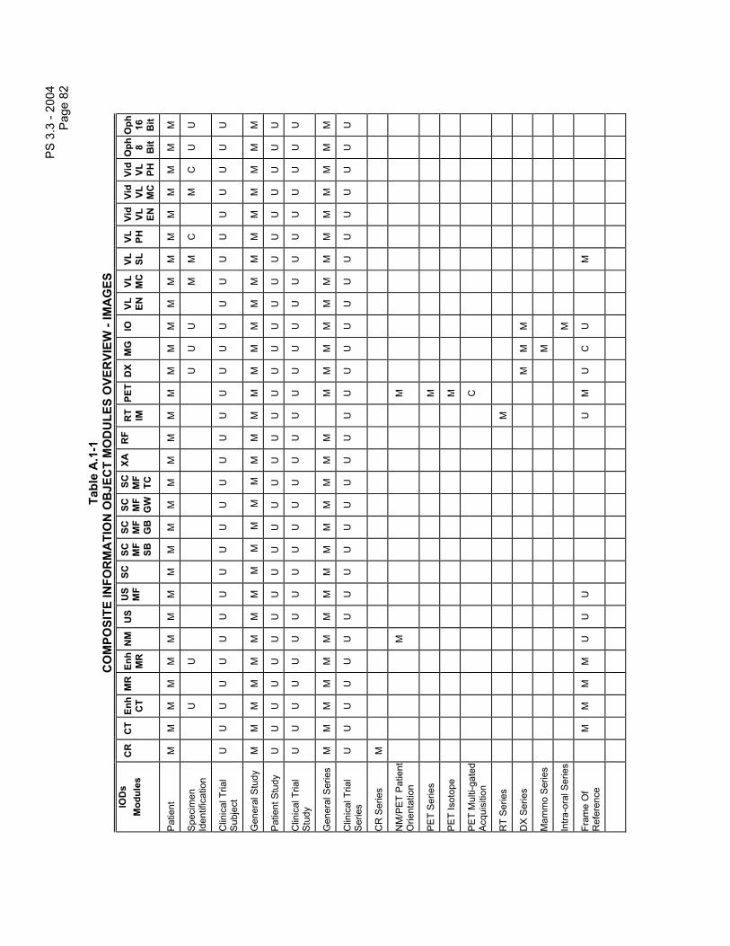
PS
3.3
- 20
04
Pag
e 82
Tabl
e A
.1-1
C
OM
POSI
TE IN
FOR
MA
TIO
N O
BJE
CT
MO
DU
LES
OVE
RVI
EW -
IMA
GES
IO
Ds
Mod
ules
C
R
CT
Enh
CT
MR
Enh
M
R
NM
US
US
MF
SCSC
M
F SB
SC
MF
GB
SC
MF
GW
SC
M
F TC
XAR
FR
T IM
PET
DX
MG
IO
VL
ENVL
M
CVL
SL
VL
PHVi
d VL
EN
Vid
VL
MC
Vid
VL
PH
Oph 8 Bit
Oph 16 Bit
Pat
ient
M
M
M
M
M
M
M
M
M
M
M
M
M
M
M
M
M
M
M
M
M
M
M
M
M
M
M
M
M
Spe
cim
en
Iden
tific
atio
n
U
U
U
U
U
M
M
C
M
C
U
U
Clin
ical
Tria
l S
ubje
ct
U
U
U
U
U
U
U
U
U
U
U
U
U
U
U
U
U
U
U
U
U
U
U
U
U
U
U
U
U
Gen
eral
Stu
dy
M
M
M
M
M
M
M
M
M
M
M
M
M
M
M
M
M
M
M
M
M
M
M
M
M
M
M
M
M
Pat
ient
Stu
dy
U
U
U
U
U
U
U
U
U
U
U
U
U
U
U
U
U
U
U
U
U
U
U
U
U
U
U
U
U
Clin
ical
Tria
l S
tudy
U
U
U
U
U
U
U
U
U
U
U
U
U
U
U
U
U
U
U
U
U
U
U
U
U
U
U
U
U
Gen
eral
Ser
ies
M
M
M
M
M
M
M
M
M
M
M
M
M
M
M
M
M
M
M
M
M
M
M
M
M
M
M
M
Clin
ical
Tria
l S
erie
s U
U
U
U
U
U
U
U
U
U
U
U
U
U
U
U
U
U
U
U
U
U
U
U
U
U
U
U
U
CR
Ser
ies
M
NM
/PE
T P
atie
nt
Orie
ntat
ion
M
M
PE
T S
erie
s
M
PE
T Is
otop
e
M
PE
T M
ulti-
gate
d A
cqui
sitio
n
C
RT
Ser
ies
M
DX
Ser
ies
M
M
M
Mam
mo
Ser
ies
M
Intra
-ora
l Ser
ies
M
Fram
e O
f R
efer
ence
M
M
M
M
U
U
U
U
M
U
C
U
M

PS
3.3
- 20
04
Pag
e 83
IOD
s M
odul
es
CR
C
T En
h C
T M
R E
nh
MR
N
MU
SU
SM
FSC
SC
MF
SB
SC
MF
GB
SC
MF
GW
SC
M
F TC
XAR
FR
T IM
PET
DX
MG
IO
VL
ENVL
M
CVL
SL
VL
PHVi
d VL
EN
Vid
VL
MC
Vid
VL
PH
Oph 8 Bit
Oph 16 Bit
Syn
chro
niza
tion
C
C
U
U
U
U
M
M
Car
diac
S
ynch
roni
zatio
n
C
C
Res
pira
tory
S
ynch
roni
zatio
n
C
C
Bul
k M
otio
n S
ynch
roni
zatio
n
C
Gen
eral
E
quip
men
t M
M
M
M
M
M
M
M
U
U
U
U
U
M
M
M
M
M
M
M
M
M
M
M
M
M
M
M
M
SC E
quipm
ent
M
M
M
M
M
Gen
eral
Imag
e M
M
M
M
M
*M
M
M
M
M
M
M
M
M
M
M
M
M
M
M
M
M
M
M
M
M
M
Im
age
Pla
ne
M
M
M
Imag
e P
ixel
M
M
M
M
M
M
M
*M
M
M
M
M
M
M
M
M
M
M
M
M
M
M
M
M
M
M
M
M
M
NM
Imag
e P
ixel
M
Pal
ette
Col
or
Look
up T
able
C
C
Sup
plem
enta
l P
alet
teC
olor
Lo
okup
Tab
le
C
C
Con
trast
/ B
olus
C
C
C
C
C
* C
C
C
C
U
U
U
Enh
ance
d C
ontra
st/
Bol
us
C
C
C
C
Cin
e
M
C
C
C
C
C
C
C
M
M
M
C
C
Mul
ti-fra
me
M
M
M
M
M
M
C
C
C
M
M
M
M
M
NM
Mul
ti-fra
me
M
Fram
e P
oint
ers
U
U
U
U
U
U
U
Mul
ti-fra
me
M
M

PS
3.3
- 20
04
Pag
e 84
IOD
s M
odul
es
CR
C
T En
h C
T M
R E
nh
MR
N
MU
SU
SM
FSC
SC
MF
SB
SC
MF
GB
SC
MF
GW
SC
M
F TC
XAR
FR
T IM
PET
DX
MG
IO
VL
ENVL
M
CVL
SL
VL
PHVi
d VL
EN
Vid
VL
MC
Vid
VL
PH
Oph 8 Bit
Oph 16 Bit
Func
tiona
l G
roup
s
Mul
ti-fra
me
Dim
ensi
on
M
M
Mas
k
C
C
Dis
play
Shu
tter
U
U
U
U
U
Dev
ice
U
U
U
U
U
Inte
rven
tion
U
U
U
U
U
CR
Imag
e M
CT
Imag
e
M
Enh
ance
d C
T Im
age
M
MR
Imag
e
M
Enh
ance
d M
R
Imag
e
M
MR
Pul
se
Seq
uenc
e
C
NM
Imag
e
M
NM
Isot
ope
M
NM
Det
ecto
r
M
NM
TO
MO
A
cqui
sitio
n
C
NM
Mul
ti-G
ated
A
cqui
sitio
n
C
NM
Pha
se
C
NM
Re
cons
tructi
on
C

PS
3.3
- 20
04
Pag
e 85
IOD
s M
odul
es
CR
C
T En
h C
T M
R E
nh
MR
N
MU
SU
SM
FSC
SC
MF
SB
SC
MF
GB
SC
MF
GW
SC
M
F TC
XAR
FR
T IM
PET
DX
MG
IO
VL
ENVL
M
CVL
SL
VL
PHVi
d VL
EN
Vid
VL
MC
Vid
VL
PH
Oph 8 Bit
Oph 16 Bit
US
Reg
ion
Cal
ibra
tion
U*
U
US
Imag
e
M
*M
SC
Imag
e
M
U
U
U
U
SC
Mul
ti-fra
me
Imag
e
M
M
M
M
SC
Mul
ti-fra
me
Vec
tor
C
C
C
C
PE
T Im
age
M
X-R
ay Im
age
M
M
X-R
ay
Acq
uisi
tion
M
M
X-R
ay
Col
limat
or
U
U
U
U
U
X-R
ay T
able
C
U
XR
F P
ositi
oner
U
X-R
ay T
omo
Acq
uisi
tion
C
U
U
U
X-R
ay
Acq
uisi
tion
Dos
e
U
U
U
X-R
ay
Gen
erat
ion
U
U
U
X-R
ay F
iltra
tion
U
U
U
X-R
ay G
rid
U
U
U
XA
Pos
ition
er
M
DX
Ana
tom
y Im
aged
M
M
M

PS
3.3
- 20
04
Pag
e 86
IOD
s M
odul
es
CR
C
T En
h C
T M
R E
nh
MR
N
MU
SU
SM
FSC
SC
MF
SB
SC
MF
GB
SC
MF
GW
SC
M
F TC
XAR
FR
T IM
PET
DX
MG
IO
VL
ENVL
M
CVL
SL
VL
PHVi
d VL
EN
Vid
VL
MC
Vid
VL
PH
Oph 8 Bit
Oph 16 Bit
DX
Imag
e
M
M
M
DX
Det
ecto
r
U
U
M
M
M
DX
Pos
ition
ing
U
U
U
Mam
mo
Imag
e
M
Intra
-ora
l Im
age
M
VL
Imag
e
M
M
M
M
M
M
M
Slid
e C
oord
inat
es
M
Oph
thal
mic
P
hoto
grap
hy
Imag
e
M
M
Ocu
lar R
egio
n Im
aged
M
M
Oph
thal
mic
P
hoto
grap
hy
Acq
uisi
tion
Par
amet
ers
M
M
Oph
thal
mic
P
hoto
grap
hic
Par
amet
ers
M
M
RT
Imag
e
M
App
rova
l
U
Ove
rlay
Pla
ne
U
U
U
U
U*
U
U
U
U
C
C
C
U
U
U
U
Mul
ti-fra
me
Ove
rlay
U
C
C
Cur
ve
Iden
tific
atio
n
M
*M
*
Cur
ve
U
U
M*
M*
U
U
U
U
U
U
Aud
io
U
U
U

PS
3.3
- 20
04
Pag
e 87
IOD
s M
odul
es
CR
C
T En
h C
T M
R E
nh
MR
N
MU
SU
SM
FSC
SC
MF
SB
SC
MF
GB
SC
MF
GW
SC
M
F TC
XAR
FR
T IM
PET
DX
MG
IO
VL
ENVL
M
CVL
SL
VL
PHVi
d VL
EN
Vid
VL
MC
Vid
VL
PH
Oph 8 Bit
Oph 16 Bit
Mod
ality
LU
T U
U
C*
C*
U
VO
I LU
T U
U
U
U
U
* U
U
C
C
U
U
U
U
C
C
C
Sof
tcop
y P
rese
ntat
ion
LUT
M
M
Imag
e H
isto
gram
U
U
U
Acq
uisi
tion
Con
text
M
M
U
M
M
M
M
M
M
M
M
M
M
SO
P C
omm
on
M
M
M
M
M
M
M*
M*
M
M
M
M
M
M
M
M
M
M
M
M
M
M
M
M
M
M
M
*
The
nota
tion
next
to M
and
U in
dica
tes
a sp
ecia
l con
ditio
n fo
r the
se m
odul
es. R
efer
to th
e co
rresp
ondi
ng In
form
atio
n O
bjec
t Def
initi
ons
in th
is A
nnex
fo
r det
ails
.
Not
es:
1. T
he o
rigin
al U
S Im
age
IOD
and
US
mul
ti-fra
me
IOD
, and
the
asso
ciat
ed U
S a
nd U
S m
ulti-
fram
e S
tora
ge S
OP
Cla
ss U
ID h
ave
been
retir
ed. N
ew
US
and
US
mul
ti-fra
me
Imag
e IO
Ds
are
defin
ed, a
s sh
own
in T
able
A.1
-1 w
hich
incl
udes
the
Pale
tte C
olor
Loo
kup
Tabl
e m
odul
e.
2.
The
orig
inal
NM
Imag
e IO
D a
nd th
e as
soci
ated
NM
Sto
rage
SO
P C
lass
UID
hav
e be
en re
tired
. A c
ompl
etel
y ne
w N
M Im
age
IOD
is d
efin
ed, a
s sh
own
in T
able
A.1
-1.


PS
3.3
- 20
04
Pag
e 89
Tabl
e A
.1-2
C
OM
POSI
TE IN
FOR
MA
TIO
N O
BJE
CT
MO
DU
LES
OVE
RVI
EW -
NO
N-IM
AG
ES
IOD
s M
odul
es
St.
OV
St.
CV
Basic
St
udy
Desc
r.
St.
Mod
LU
T
St.
VOI
LUT
Pres
St
M
R
Spec
t R
aw
Dat
a R
T D
ose
RT
Stru
c Se
t
RT
Plan
RT
Bea
m
Rec
RT
Bch
y R
ec
RT
Sum
PET
CV
Bas
ic
Voic
e Au
dio
12
Lead
EC
G
Gen
EC
G
WF
Amb
ECG
W
F
Hem
o W
F B
asic
C
ard
EP
Bas
ic
Text
SR
Enha
nSR
C
omp
SR
Key
O
bjec
t Se
ln
Mam
C
AD
Che
st
CAD
R
eg
Fid
Ster
eo
Rel
n
Pat
ient
M
M
M
M
M
M
M
M
M
M
M
M
M
M
M
M
M
M
M
M
M
M
M
M
M
M
M
M
M
Pat
ient
S
umm
ary
M
Spe
cim
en
Iden
tific
atio
n
U
U
C
C
C
C
C
C
C
Clin
ical
Tria
l S
ubje
ct
U
U
U
U
U
U
U
U
U
U
U
U
U
U
U
U
U
U
U
U
U
U
U
U
U
U
U
U
U
U
Gen
eral
Stu
dy
M
M
M
M
M
M
M
M
M
M
M
M
M
M
M
M
M
M
M
M
M
M
M
M
M
M
M
M
M
Pat
ient
Stu
dy
U
U
U
U
U
U
U
U
U
U
U
U
U
U
U
U
U
U
U
U
U
U
U
U
U
U
U
U
U
Clin
ical
Tria
l S
tudy
U
U
U
U
U
U
U
U
U
U
U
U
U
U
U
U
U
U
U
U
U
U
U
U
U
U
U
U
U
U
Stu
dy C
onte
nt
M
Gen
eral
Ser
ies
M
M
M
M
M
M
M
M
M
M
M
M
M
M
Clin
ical
Tria
l S
erie
s U
U
U
U
U
U
U
U
U
U
U
U
U
U
U
U
U
U
U
U
U
U
U
U
U
U
U
U
U
Spa
tial
Reg
istra
tion
Ser
ies
M
Spa
tial
Fidu
cial
s S
erie
s
M
Ste
reom
etric
S
erie
s
M
PE
T S
erie
s
M
PE
T Is
otop
e
M
PE
T M
ulti-
gate
d A
cqui
sitio
n
C
RT
Ser
ies
M
M
M
M
M
M

PS
3.3
- 20
04
Pag
e 90
IOD
s M
odul
es
St.
OV
St.
CV
Basic
St
udy
Desc
r.
St.
Mod
LU
T
St.
VOI
LUT
Pres
St
M
R
Spec
t R
aw
Dat
a R
T D
ose
RT
Stru
c Se
t
RT
Plan
RT
Bea
m
Rec
RT
Bch
y R
ec
RT
Sum
PET
CV
Bas
ic
Voic
e Au
dio
12
Lead
EC
G
Gen
EC
G
WF
Amb
ECG
W
F
Hem
o W
F B
asic
C
ard
EP
Bas
ic
Text
SR
Enha
nSR
C
omp
SR
Key
O
bjec
t Se
ln
Mam
C
AD
Che
st
CAD
R
eg
Fid
Ster
eo
Rel
n
Pre
sent
atio
n S
erie
s
M
SR
Doc
umen
t S
erie
s
M
M
M
M
M
Key
Obj
ect
Doc
umen
t S
erie
s
M
Fram
e O
f R
efer
ence
M
U
M
U
U
M
Syn
chro
niza
tion
C
C
U
U
U
U
C
C
U
Car
diac
S
ynch
roni
zatio
n
C
Res
pira
tory
S
ynch
roni
zatio
n
C
Bul
k M
otio
n S
ynch
roni
zatio
n
C
Gen
eral
E
quip
men
t M
M
M
M
M
M
M
M
M
M
M
M
M
M
M
M
M
M
M
M
M
M
M
M
M
M
M
M
M
Gen
eral
Imag
e
C
Imag
e P
lane
C
Imag
e P
ixel
C
Mul
ti-fra
me
C
Mul
ti-fra
me
Func
tiona
l G
roup
s
M
Mul
ti-fra
me
Dim
ensi
on
M
Mas
k
C
Dis
play
Shu
tter
C
Bitm
ap D
ispl
ay
C
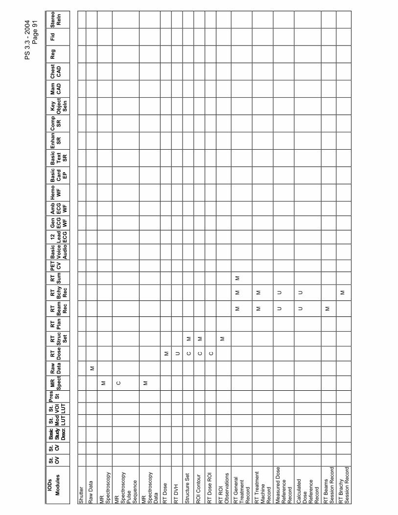
PS
3.3
- 20
04
Pag
e 91
IOD
s M
odul
es
St.
OV
St.
CV
Basic
St
udy
Desc
r.
St.
Mod
LU
T
St.
VOI
LUT
Pres
St
M
R
Spec
t R
aw
Dat
a R
T D
ose
RT
Stru
c Se
t
RT
Plan
RT
Bea
m
Rec
RT
Bch
y R
ec
RT
Sum
PET
CV
Bas
ic
Voic
e Au
dio
12
Lead
EC
G
Gen
EC
G
WF
Amb
ECG
W
F
Hem
o W
F B
asic
C
ard
EP
Bas
ic
Text
SR
Enha
nSR
C
omp
SR
Key
O
bjec
t Se
ln
Mam
C
AD
Che
st
CAD
R
eg
Fid
Ster
eo
Rel
n
Shu
tter
Raw
Dat
a
M
MR
S
pect
rosc
opy
M
MR
S
pect
rosc
opy
Pul
se
Seq
uenc
e
C
MR
S
pect
rosc
opy
Dat
a
M
RT
Dos
e
M
RT
DV
H
U
Stru
ctur
e S
et
C
M
RO
I Con
tour
C
M
RT
Dos
e R
OI
C
RT
RO
I O
bser
vatio
ns
M
RT
Gen
eral
Tr
eatm
ent
Rec
ord
M
M
M
RT
Trea
tmen
t M
achi
ne
Rec
ord
M
M
Mea
sure
d D
ose
Ref
eren
ce
Rec
ord
U
U
Cal
cula
ted
Dos
e R
efer
ence
R
ecor
d
U
U
RT
Bea
ms
Ses
sion
Rec
ord
M
RT
Bra
chy
Ses
sion
Rec
ord
M

PS
3.3
- 20
04
Pag
e 92
IOD
s M
odul
es
St.
OV
St.
CV
Basic
St
udy
Desc
r.
St.
Mod
LU
T
St.
VOI
LUT
Pres
St
M
R
Spec
t R
aw
Dat
a R
T D
ose
RT
Stru
c Se
t
RT
Plan
RT
Bea
m
Rec
RT
Bch
y R
ec
RT
Sum
PET
CV
Bas
ic
Voic
e Au
dio
12
Lead
EC
G
Gen
EC
G
WF
Amb
ECG
W
F
Hem
o W
F B
asic
C
ard
EP
Bas
ic
Text
SR
Enha
nSR
C
omp
SR
Key
O
bjec
t Se
ln
Mam
C
AD
Che
st
CAD
R
eg
Fid
Ster
eo
Rel
n
RT
Trea
tmen
t S
umm
ary
Rec
ord
U
U
M
RT
Gen
eral
P
lan
M
RT
Pre
scrip
tion
U
RT
Tole
ranc
e Ta
bles
U
RT
Pat
ient
S
etup
U
U
U
RT
Frac
tion
Sch
eme
U
RT
Bea
ms
C
RT
Bra
chy
App
licat
ion
Set
ups
C
App
rova
l
U
U
Ste
reom
etric
R
elat
ions
hip
M
SR
Doc
umen
t G
ener
al
M
M
M
M
M
SR
Doc
umen
t C
onte
nt
M
M
M
M
M
M
Key
Obj
ect
Doc
umen
t
M
Ove
rlay
Iden
tific
atio
n M
Ove
rlay
Pla
ne
M
C
U
Mul
ti-fra
me
Ove
rlay
U
Cur
ve
Iden
tific
atio
n
M
M
Cur
ve
M
U
U
U
M

PS
3.3
- 20
04
Pag
e 93
IOD
s M
odul
es
St.
OV
St.
CV
Basic
St
udy
Desc
r.
St.
Mod
LU
T
St.
VOI
LUT
Pres
St
M
R
Spec
t R
aw
Dat
a R
T D
ose
RT
Stru
c Se
t
RT
Plan
RT
Bea
m
Rec
RT
Bch
y R
ec
RT
Sum
PET
CV
Bas
ic
Voic
e Au
dio
12
Lead
EC
G
Gen
EC
G
WF
Amb
ECG
W
F
Hem
o W
F B
asic
C
ard
EP
Bas
ic
Text
SR
Enha
nSR
C
omp
SR
Key
O
bjec
t Se
ln
Mam
C
AD
Che
st
CAD
R
eg
Fid
Ster
eo
Rel
n
PE
T C
urve
M
Aud
io
U
U
U
Wav
efor
m
Iden
tific
atio
n
M
M
M
M
M
M
Wav
efor
m
M
M
M
M
M
M
Wav
efor
m
Ann
otat
ion
U
C
C
C
C
C
Dis
play
ed A
rea
M
Ove
rlay/
Cur
ve
Act
ivat
ion
C
Gra
phic
A
nnot
atio
n
C
Spa
tial
Tran
sfor
mat
ion
C
Gra
phic
Lay
er
C
Mod
ality
LU
T
M
C
U
VO
I LU
T
M
Sof
tcop
y V
OI
LUT
C
Sof
tcop
y P
rese
ntat
ion
LU
T
M
Imag
e H
isto
gram
Pre
sent
atio
n S
tate
M
LUT
Iden
tific
atio
n
M
M
Spa
tial
Reg
istra
tion
M

PS
3.3
- 20
04
Pag
e 94
IOD
s M
odul
es
St.
OV
St.
CV
Basic
St
udy
Desc
r.
St.
Mod
LU
T
St.
VOI
LUT
Pres
St
M
R
Spec
t R
aw
Dat
a R
T D
ose
RT
Stru
c Se
t
RT
Plan
RT
Bea
m
Rec
RT
Bch
y R
ec
RT
Sum
PET
CV
Bas
ic
Voic
e Au
dio
12
Lead
EC
G
Gen
EC
G
WF
Amb
ECG
W
F
Hem
o W
F B
asic
C
ard
EP
Bas
ic
Text
SR
Enha
nSR
C
omp
SR
Key
O
bjec
t Se
ln
Mam
C
AD
Che
st
CAD
R
eg
Fid
Ster
eo
Rel
n
Spa
tial
Fidu
cial
s
M
Com
mon
In
stan
ce
Ref
eren
ce
M
M
M
Acq
uisi
tion
Con
text
M
M
M
M
M
U
M
M
SO
P C
omm
on
M
M
M
M
M
M
M
M
M
M
M
M
M
M
M
M
M
M
M
M
M
M
M
M
M
M
M
M
M
*
The
nota
tion
next
to M
and
U in
dica
tes
a sp
ecia
l con
ditio
n fo
r the
se m
odul
es. R
efer
to th
e co
rresp
ondi
ng In
form
atio
n O
bjec
t Def
initi
ons
in th
is A
nnex
for d
etai
ls.

PS 3.3 - 2004 Page 95
A.2 COMPUTED RADIOGRAPHY IMAGE INFORMATION OBJECT DEFINITION
A.2.1 CR Image IOD Description The Computed Radiography (CR) Image Information Object Definition specifies an image that has been created by a computed radiography imaging device.
Note: Digital Luminescence Radiography is an equivalent term for computed Radiography.
A.2.2 CR Image IOD Entity-Relationship Model The E-R Model in Section A.1.2 depicts those components of the DICOM Information Model that directly reference the CR Image IOD. The Frame of Reference IE, Overlay IE, Modality LUT IE, VOI LUT IE and Curve IE are not components of the CR Image IOD.
A.2.3 CR Image IOD Module Table Table A.2-1
CR IMAGE IOD MODULES IE Module Reference Usage Patient Patient C.7.1.1 M Clinical Trial Subject C.7.1.3 U Study General Study C.7.2.1 M Patient Study C.7.2.2 U Clinical Trial Study C.7.2.3 U Series General Series C.7.3.1 M CR Series C.8.1.1 M Clinical Trial Series C.7.3.2 U Equipment General Equipment C.7.5.1 M Image General Image C.7.6.1 M Image Pixel C.7.6.3 M Contrast/bolus C.7.6.4 C - Required if contrast media was
used in this image CR Image C.8.1.2 M Overlay Plane C.9.2 U Curve C.10.2 U Modality LUT C.11.1 U VOILUT C.11.2 U SOP Common C.12.1 M
A.3 COMPUTED TOMOGRAPHY IMAGE INFORMATION OBJECT DEFINITION A.3.1 CT Image IOD Description The Computed Tomography (CT) Image Information Object Definition (IOD) specifies an image that has been created by a computed tomography imaging device.
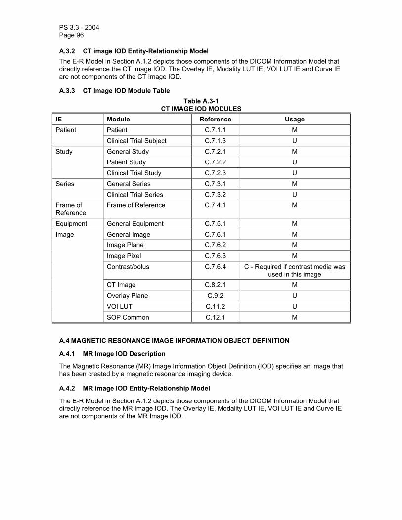
PS 3.3 - 2004 Page 96
A.3.2 CT image IOD Entity-Relationship Model The E-R Model in Section A.1.2 depicts those components of the DICOM Information Model that directly reference the CT Image IOD. The Overlay IE, Modality LUT IE, VOI LUT IE and Curve IE are not components of the CT Image IOD.
A.3.3 CT Image IOD Module Table Table A.3-1
CT IMAGE IOD MODULES IE Module Reference Usage Patient Patient C.7.1.1 M Clinical Trial Subject C.7.1.3 U Study General Study C.7.2.1 M Patient Study C.7.2.2 U Clinical Trial Study C.7.2.3 U Series General Series C.7.3.1 M Clinical Trial Series C.7.3.2 U Frame of Reference
Frame of Reference C.7.4.1 M
Equipment General Equipment C.7.5.1 M Image General Image C.7.6.1 M Image Plane C.7.6.2 M Image Pixel C.7.6.3 M Contrast/bolus C.7.6.4 C - Required if contrast media was
used in this image CT Image C.8.2.1 M Overlay Plane C.9.2 U VOI LUT C.11.2 U SOP Common C.12.1 M
A.4 MAGNETIC RESONANCE IMAGE INFORMATION OBJECT DEFINITION
A.4.1 MR Image IOD Description
The Magnetic Resonance (MR) Image Information Object Definition (IOD) specifies an image that has been created by a magnetic resonance imaging device.
A.4.2 MR image IOD Entity-Relationship Model
The E-R Model in Section A.1.2 depicts those components of the DICOM Information Model that directly reference the MR Image IOD. The Overlay IE, Modality LUT IE, VOI LUT IE and Curve IE are not components of the MR Image IOD.

PS 3.3 - 2004 Page 97
A.4.3 MR Image IOD Module Table Table A.4-1
MR IMAGE IOD MODULES IE Module Reference Usage Patient Patient C.7.1.1 M Clinical Trial Subject C.7.1.3 U Study General Study C.7.2.1 M Patient Study C.7.2.2 U Clinical Trial Study C.7.2.3 U Series General Series C.7.3.1 M Clinical Trial Series C.7.3.2 U Frame of Reference
Frame of Reference C.7.4.1 M
Equipment General Equipment C.7.5.1 M Image General Image C.7.6.1 M Image Plane C.7.6.2 M Image Pixel C.7.6.3 M Contrast/bolus C.7.6.4 C - Required if contrast media was
used in this image MR Image C.8.3.1 M Overlay Plane C.9.2 U VOI LUT C.11.2 U SOP Common C.12.1 M
A.5 NUCLEAR MEDICINE IMAGE INFORMATION OBJECT DEFINITION
A.5.1 NM Image IOD Description
The Nuclear Medicine (NM) Image Information Object Definition (IOD) specifies an image that has been created by a nuclear medicine imaging device. This includes data created by external detection devices that create images of the distribution of administered radioactive materials in the body. Depending on the specific radio pharmaceutical administered and the particular imaging procedure performed, problems involving changes in metabolism, function, or physiology can be investigated and various regional pathologies can be studied.
A.5.2 NM Image IOD Entity-Relationship Model
The E-R Model in Section A.1.2 depicts those components of the DICOM Information Model that directly reference the NM Image IOD. The Modality LUT IE is not a component of the NM Image IOD.
A.5.3 NM Image IOD Module Table (Retired)
Section A.5.3 was defined in a previous version of the DICOM Standard. The Section is now retired.

PS 3.3 - 2004 Page 98
A.5.4 NM Image IOD Module Table Table A.5-1
NM IMAGE IOD MODULES IE Module Reference Usage Patient Patient C.7.1.1 M Clinical Trial Subject C.7.1.3 U Study General Study C.7.2.1 M Patient Study C.7.2.2 U Clinical Trial Study C.7.2.3 U Series General Series C.7.3.1 M Clinical Trial Series C.7.3.2 U NM/PET Patient Orientation C.8.4.6 M Frame of Reference
Frame of Reference C.7.4.1 U
Equipment General Equipment C.7.5.1 M Image General Image C.7.6.1 M Image Pixel C.7.6.3 M Acquisition Context C.7.6.14 U – See Section A.5.4.1 NM Image Pixel C.8.4.7 M Multi-frame C.7.6.6 M NM Multi-frame C.8.4.8 M NM Image C.8.4.9 M NM Isotope C.8.4.10 M NM Detector C.8.4.11 M NM TOMO Acquisition C.8.4.12 C - Required if Image Type
(0008,0008) Value 3 is TOMO, GATED TOMO, RECON TOMO or
RECON GATED TOMO NM Multi-gated Acquisition C.8.4.13 C - Required if Image Type
(0008,0008) Value 3 is GATED, GATED TOMO, or RECON GATED
TOMO NM Phase C.8.4.14 C - Required if Image Type
(0008,0008) Value 3 is DYNAMIC NM Reconstruction C.8.4.15 C - Required if Image Type
(0008,0008) Value 3 is RECON TOMO or RECON GATED TOMO
Overlay Plane C.9.2 U Multi-frame Overlay C.9.3 U Curve C.10.2 U VOI LUT C.11.2 U SOP Common C.12.1 M

PS 3.3 - 2004 Page 99
A.5.4.1 Acquisition Context Module The Defined Template for Acquisition Context Sequence (0040,0555) is TID 3470.
The Acquisition Context Sequence (0040,0555) shall always apply to all frames in the Image. Patient State shall always apply to all frames in the Image, therefore, Referenced Frame Numbers (0040,A136) shall not be present.
A.6 ULTRASOUND IMAGE INFORMATION OBJECT DEFINITION
A.6.1 US Image IOD Description
The Ultrasound (US) Image Information Object Definition specifies an image that has been created by an ultrasound imaging device.
A.6.2 US Image IOD Entity-Relationship Model
The E-R Model in Section A.1.2 depicts those components of the DICOM Information Model that directly reference the US Image IOD. The Overlay IE, Modality LUT IE and VOI LUT IE are not components of the US Image IOD.
A.6.3 US Image IOD Module Table (Retired)
Section A.6.3 was defined in a previous version of the DICOM Standard. The Section is now retired.

PS 3.3 - 2004 Page 100
A.6.4 US Image IOD Module Table Table A.6-1
US IMAGE IOD MODULES IE Module Reference Usage Patient Patient C.7.1.1 M
Clinical Trial Subject C.7.1.3 U
Study General Study C.7.2.1 M
Patient Study C.7.2.2 U
Clinical Trial Study C.7.2.3 U
Series General Series C.7.3.1 M
Clinical Trial Series C.7.3.2 U
Frame of Reference
Frame of Reference C.7.4.1 U
Synchronization C.7.4.2 U Equipment General Equipment C.7.5.1 M
Image General Image C.7.6.1 M
(See A.6.4.1) Image Pixel C.7.6.3 M
Contrast/bolus C.7.6.4 C - Required if contrast media was used in this image
Palette Color Lookup Table C.7.9 C - Required if Photometic Interpretation (0028,0004) has a
value of PALETTE COLOR US Region Calibration C.8.5.5 U
US Image C.8.5.6 M Overlay Plane C.9.2 U VOI LUT C.11.2 U
SOP Common C.12.1 M
Curve Curve Identification C.10.1 M
(See A.6.4.1) Curve C.10.2 M
Audio C.10.3 U
SOP Common C.12.1 M
Notes: 1. For the purpose of conveying ultrasound protocol data management information it is recommended that the Performed Protocol Code Sequence (0040,0260) be assigned the code value(s) of the performed ultrasound protocol, if any. The Baseline Context Group for these code values is Context ID 12001 (defined in PS 3.16).
2. The US Frame of Reference Module was previously included in this IOD, but has been retired. See PS 3.3 2003.

PS 3.3 - 2004 Page 101
A.6.4.1 Mutually Exclusive IEs The Image and Curve IEs are mutually exclusive. Each SOP Instance using this IOD shall contain exactly one of these IEs.
A.7 ULTRASOUND MULTI-FRAME IMAGE INFORMATION OBJECT DEFINITION A.7.1 US Image IOD Description The Ultrasound (US) Multi-frame Image Information Object Definition specifies a Multi-frame image that has been created by an ultrasound imaging device.
A.7.2 US Multi-Frame Image IOD Entity-Relationship Model The E-R Model in Section A.1.2 depicts those components of the DICOM Application Information Model that directly reference the US Multi-frame Image IOD. The Overlay IE, Modality LUT IE and VOI LUT IE are not components of the US Multi-frame Image IOD.
A.7.3 US Image IOD Module Table (Retired) Section A.7.3 was defined in a previous version of the DICOM Standard. The Section is now retired.

PS 3.3 - 2004 Page 102
A.7.4 US Multi-Frame Image IOD Module Table Table A.7-1
US MULTI-FRAME IMAGE IOD MODULES IE Module Reference Usage Patient Patient C.7.1.1 M Clinical Trial Subject C.7.1.3 U Study General Study C.7.2.1 M Patient Study C.7.2.2 U Clinical Trial Study C.7.2.3 U Series General Series C.7.3.1 M Clinical Trial Series C.7.3.2 U Frame of Frame of Reference C.7.4.1 U Reference Synchronization C.7.4.2 C – Required if Modality
(0008,0060) = IVUS. May be present otherwise.
Equipment General Equipment C.7.5.1 M Image General Image C.7.6.1 M (See A.7.4.1) Image Pixel C.7.6.3 M Contrast/bolus C.7.6.4 C - Required if contrast media was
used in this image. Cine C.7.6.5 M Multi-frame C.7.6.6 M Frame Pointers C.7.6.9 U Palette Color Lookup Table C.7.9 C - Required if Photometric
Interpretation (0028,0004) has a value of PALETTE COLOR
US Region Calibration C.8.5.5 U US Image C.8.5.6 M VOI LUT C.11.2 U SOP Common C.12.1 M Curve Curve Identification C.10.1 M (see A.7.4.1) Curve C.10.2 M
Audio C.10.3 U
SOP Common C.12.1 M
Notes: 1. For the purpose of conveying ultrasound protocol data management information it is recommended that the Performed Protocol Code Sequence (0040,0260) be assigned the code value(s) of the performed ultrasound protocol, if any. The Baseline Context Group for these code values is Context ID 12001 (defined in PS 3.16).
2. The US Frame of Reference Module was previously included in this IOD, but has been retired. See PS 3.3 2003.
PS 3.3 - 2004 Page 103
A.7.4.1 Mutually Exclusive IEs The Image and Curve IEs are mutually exclusive. Each SOP Instance using this IOD shall contain exactly one of these IEs.
A.8 SECONDARY CAPTURE IMAGE INFORMATION OBJECT DEFINITION
The Secondary Capture (SC) Image Information Object Definition (IOD) specifies images that are converted from a non-DICOM format to a modality independent DICOM format.
Examples of types of equipment that create Secondary Capture Images include:
a. Video interfaces that convert an analog video signal into a digital image b. Digital interfaces that are commonly used to transfer non-DICOM digital images from an
imaging device to a laser printer c. Film digitizers that convert an analog film image to digital data d. Workstations that construct images that are sent out as a screen dump e. Scanned documents and other bitmap images including hand-drawings f. Synthesized images that are not modality-specific, such as cine-loops of 3D
reconstructions
Originally, a single, relatively unconstrained, single-frame SC Image IOD was defined in the DICOM Standard. Though this IOD is retained and not retired since it is in common use, more specific IODs for particular categories of application are also defined.
The following IODs are all multi-frame. A single frame image is encoded as a multi-frame image with only one frame. The multi-frame SC IODs consist of:
- Multi-frame Single Bit Secondary Capture Image IOD - Multi-frame Grayscale Byte Secondary Capture Image IOD - Multi-frame Grayscale Word Secondary Capture Image IOD - Multi-frame True Color Secondary Capture Image IOD
A.8.1 SC Image Information Objection Definition A.8.1.1 SC Image IOD Description The Secondary Capture (SC) Image Information Object Definition (IOD) specifies single-frame images that are converted from a non-DICOM format to a modality independent DICOM format, without any constraints on pixel data format.
Note: The use of this IOD is deprecated, and other more specific SC Image IODs should be used.
A.8.1.2 SC Image IOD Entity-Relationship Model The E-R Model in Section A.1.2 depicts those components of the DICOM Information Model that directly reference the Secondary Capture Image IOD. The Frame of Reference IE and Curve IE are not components of this IOD.

PS 3.3 - 2004 Page 104
A.8.1.3 SC Image IOD Module Table Table A.8-1
SC IMAGE IOD MODULES IE Module Reference Usage Patient Patient C.7.1.1 M Clinical Trial Subject C.7.1.3 U Study General Study C.7.2.1 M Patient Study C.7.2.2 U Clinical Trial Study C.7.2.3 U Series General Series C.7.3.1 M Clinical Trial Series C.7.3.2 U Equipment General Equipment C.7.5.1 U SC Equipment C.8.6.1 M Image General Image C.7.6.1 M Image Pixel C.7.6.3 M SC Image C.8.6.2 M Overlay Plane C.9.2 U Modality LUT C.11.1 U VOI LUT C.11.2 U SOP Common C.12.1 M
A.8.2 Multi-frame Single Bit SC Image Information Object Definition A.8.2.1 Multi-frame Single Bit SC Image IOD Description The Multi-frame Single Bit Secondary Capture (SC) Image Information Object Definition (IOD) specifies images that are converted from a non-DICOM format to a modality independent DICOM format.
This IOD is typically used for scanned documents and bitmap images of hand drawings.
A.8.2.2 Multi-frame Single Bit SC Image IOD Entity-Relationship Model The E-R Model in Section A.1.2 depicts those components of the DICOM Information Model that directly reference the Secondary Capture Image family of IODs. The Frame of Reference IE, Overlay IE, Modality LUT IE, VOI LUT IE and Curve IE are not components of this IOD.

PS 3.3 - 2004 Page 105
A.8.2.3 Multi-frame Single Bit SC Image IOD Module Table Table A.8-2
MULTI-FRAME SINGLE BIT SC IMAGE IOD MODULES IE Module Reference Usage Patient Patient C.7.1.1 M Clinical Trial Subject C.7.1.3 U Study General Study C.7.2.1 M Patient Study C.7.2.2 U Clinical Trial Study C.7.2.3 U Series General Series C.7.3.1 M Clinical Trial Series C.7.3.2 U Equipment General Equipment C.7.5.1 U SC Equipment C.8.6.1 M Image General Image C.7.6.1 M Image Pixel C.7.6.3 M Cine C.7.6.5 C – Required if Frame Increment
Pointer (0028,0009) is Frame Time (0018,1063) or Frame Time Vector
(0018,1065) Multi-frame C.7.6.6 M Frame Pointers C.7.6.9 U SC Image C.8.6.2 U SC Multi-frame Image C.8.6.3 M SC Multi-frame Vector C.8.6.4 C – Required if Number of Frames
is greater than 1 SOP Common C.12.1 M
A.8.2.4 Multi-frame Single Bit SC Image IOD Content Constraints In the Image Pixel Module, the following constraints apply:
- Samples per Pixel (0028,0002) shall be 1 - Photometric Interpretation (0028,0004) shall be MONOCHROME2 - Bits Allocated (0028,0100) shall be 1 - Bits Stored (0028,0101) shall be 1 - High Bit (0028,0102) shall be 0 - Pixel Representation (0028,0103) shall be 0 - Planar Configuration (0028,0006) shall not be present
Note: As a consequence of these attribute values, single bit pixels are packed eight to a byte as defined by the encoding rules in PS 3.5.
The VOI LUT module shall not be present.
The Overlay module shall not be present.

PS 3.3 - 2004 Page 106
A.8.3 Multi-frame Grayscale Byte SC Image Information Object Definition A.8.3.1 Multi-frame Grayscale Byte Image IOD Description The Multi-frame Grayscale Byte Secondary Capture (SC) Image Information Object Definition (IOD) specifies Grayscale Byte images that are converted from a non-DICOM format to a modality independent DICOM format.
This IOD is typically used for screen captured images for modalities that have pixel values of 8 bits, but may also be appropriate for scanned grayscale documents.
A.8.3.2 Multi-frame Grayscale Byte SC Image IOD Entity-Relationship Model The E-R Model in Section A.1.2 depicts those components of the DICOM Information Model that directly reference the Secondary Capture Image family of IODs. The Frame of Reference IE, Overlay IE, Modality LUT IE and Curve IE are not components of this IOD.
A.8.3.3 Multi-frame Grayscale Byte SC Image IOD Module Table Table A.8-3
MULTI-FRAME GRAYSCALE BYTE SC IMAGE IOD MODULES IE Module Reference Usage Patient Patient C.7.1.1 M Clinical Trial Subject C.7.1.3 U Study General Study C.7.2.1 M Patient Study C.7.2.2 U Clinical Trial Study C.7.2.3 U Series General Series C.7.3.1 M Clinical Trial Series C.7.3.2 U Equipment General Equipment C.7.5.1 U SC Equipment C.8.6.1 M Image General Image C.7.6.1 M Image Pixel C.7.6.3 M Cine C.7.6.5 C – Required if Frame Increment
Pointer (0028,0009) is Frame Time (0018,1063) or Frame Time Vector
(0018,1065) Multi-frame C.7.6.6 M Frame Pointers C.7.6.9 U SC Image C.8.6.2 U SC Multi-frame Image C.8.6.3 M SC Multi-frame Vector C.8.6.4 C – Required if Number of Frames
is greater than 1 VOI LUT C.11.2 C – Required if the VOI LUT stage
is not an identity transformation SOP Common C.12.1 M

PS 3.3 - 2004 Page 107
A.8.3.4 Multi-frame Grayscale Byte SC Image IOD Content Constraints The VOI LUT module is required if the VOI LUT stage is not an identity transformation. Support for both window and LUT is mandatory. The output grayscale space is defined to be in P-Values.
Note: If the VOI LUT module is absent, then the stored pixel values are in P-Values.
In the Image Pixel Module, the following constraints apply:
- Samples per Pixel (0028,0002) shall be 1 - Photometric Interpretation (0028,0004) shall be MONOCHROME2 - Bits Allocated (0028,0100) shall be 8 - Bits Stored (0028,0101) shall be 8 - High Bit (0028,0102) shall be 7 - Pixel Representation (0028,0103) shall be 0 - Planar Configuration (0028,0006) shall not be present
The Overlay module shall not be present.
A.8.4 Multi-frame Grayscale Word SC Image Information Object Definition A.8.4.1 Multi-frame Grayscale Word SC Image IOD Description The Multi-frame Grayscale Word Secondary Capture (SC) Image Information Object Definition (IOD) specifies Grayscale Word images that are converted from a non-DICOM format to a modality independent DICOM format.
This IOD is typically used for screen captured images for modalities that have pixel values greater than 8 bits.
A.8.4.2 Multi-frame Grayscale Word SC Image IOD Entity-Relationship Model The E-R Model in Section A.1.2 depicts those components of the DICOM Information Model that directly reference the Secondary Capture Image family of IODs. The Frame of Reference IE, Overlay IE, Modality LUT IE and Curve IE are not components this IOD.

PS 3.3 - 2004 Page 108
A.8.4.3 Multi-frame Grayscale Word SC Image IOD Module Table Table A.8-4
MULTI-FRAME GRAYSCALE WORD SC IMAGE IOD MODULES IE Module Reference Usage Patient Patient C.7.1.1 M Clinical Trial Subject C.7.1.3 U Study General Study C.7.2.1 M Patient Study C.7.2.2 U Clinical Trial Study C.7.2.3 U Series General Series C.7.3.1 M Clinical Trial Series C.7.3.2 U Equipment General Equipment C.7.5.1 U SC Equipment C.8.6.1 M Image General Image C.7.6.1 M Image Pixel C.7.6.3 M Cine C.7.6.5 C – Required if Frame Increment
Pointer (0028,0009) is Frame Time (0018,1063) or Frame Time Vector
(0018,1065) Multi-frame C.7.6.6 M Frame Pointers C.7.6.9 U SC Image C.8.6.2 U SC Multi-frame Image C.8.6.3 M SC Multi-frame Vector C.8.6.4 C – Required if Number of Frames
is greater than 1 VOI LUT C.11.2 C – Required if the VOI LUT stage
is not an identity transformation SOP Common C.12.1 M
A.8.4.4 Multi-frame Grayscale Word SC Image IOD Content Constraints The VOI LUT module is required if the VOI LUT stage is not an identity transformation. Support for both window and LUT is mandatory. The output grayscale space is defined to be in P-Values.
Note: If the VOI LUT module is absent, then the stored pixel values are in P-Values.
In the Image Pixel Module, the following constraints apply:
- Samples per Pixel (0028,0002) shall be 1 - Photometric Interpretation (0028,0004) shall be MONOCHROME2 - Bits Allocated (0028,0100) shall be 16 - Bits Stored (0028,0101) shall be greater than or equal to 9 and less than or equal to 16 - High Bit (0028,0102) shall be one less than Bits Stored (0028,0101) - Pixel Representation (0028,0103) shall be 0 - Planar Configuration (0028,0006) shall not be present

PS 3.3 - 2004 Page 109
The Overlay module shall not be present. Unused high bits shall be filled with zeroes.
A.8.5 Multi-frame True Color SC Image Information Object Definition A.8.5.1 Multi-frame True Color Image IOD Description The Multi-frame True Color Secondary Capture (SC) Image Information Object Definition (IOD) specifies True Color images that are converted from a non-DICOM format to a modality independent DICOM format.
This IOD is typically used for screen captured or synthetic images where true color is used, but may also be appropriate for scanned color documents.
A.8.5.2 Multi-frame True Color SC Image IOD Entity-Relationship Model The E-R Model in Section A.1.2 depicts those components of the DICOM Information Model that directly reference the Secondary Capture Image family of IODs. The Frame of Reference IE, Overlay IE, Modality LUT IE, VOI LUT IE and Curve IE are not components of the this IOD.
A.8.5.3 Multi-frame True Color SC Image IOD Module Table Table A.8-5
MULTI-FRAME TRUE COLOR SC IMAGE IOD MODULES IE Module Reference Usage Patient Patient C.7.1.1 M Clinical Trial Subject C.7.1.3 U Study General Study C.7.2.1 M Patient Study C.7.2.2 U Clinical Trial Study C.7.2.3 U Series General Series C.7.3.1 M Clinical Trial Series C.7.3.2 U Equipment General Equipment C.7.5.1 U SC Equipment C.8.6.1 M Image General Image C.7.6.1 M Image Pixel C.7.6.3 M Cine C.7.6.5 C – Required if Frame Increment
Pointer (0028,0009) is Frame Time (0018,1063) or Frame Time Vector
(0018,1065) Multi-frame C.7.6.6 M Frame Pointers C.7.6.9 U SC Image C.8.6.2 U SC Multi-frame Image C.8.6.3 M SC Multi-frame Vector C.8.6.4 C – Required if Number of Frames
is greater than 1 SOP Common C.12.1 M
A.8.5.4 Multi-frame True Color SC Image IOD Content Constraints The VOI LUT module shall not be present.
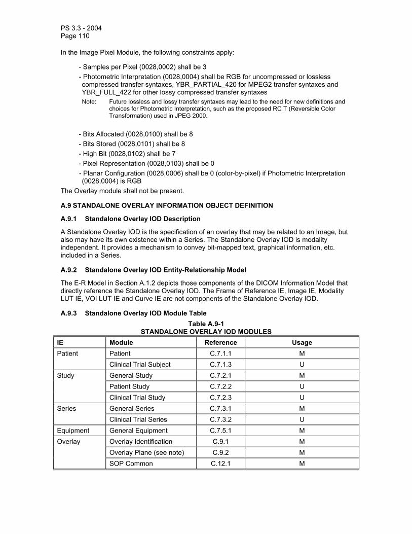
PS 3.3 - 2004 Page 110
In the Image Pixel Module, the following constraints apply:
- Samples per Pixel (0028,0002) shall be 3 - Photometric Interpretation (0028,0004) shall be RGB for uncompressed or lossless compressed transfer syntaxes, YBR_PARTIAL_420 for MPEG2 transfer syntaxes and YBR_FULL_422 for other lossy compressed transfer syntaxes Note: Future lossless and lossy transfer syntaxes may lead to the need for new definitions and
choices for Photometric Interpretation, such as the proposed RC T (Reversible Color Transformation) used in JPEG 2000.
- Bits Allocated (0028,0100) shall be 8 - Bits Stored (0028,0101) shall be 8 - High Bit (0028,0102) shall be 7 - Pixel Representation (0028,0103) shall be 0 - Planar Configuration (0028,0006) shall be 0 (color-by-pixel) if Photometric Interpretation (0028,0004) is RGB
The Overlay module shall not be present.
A.9 STANDALONE OVERLAY INFORMATION OBJECT DEFINITION
A.9.1 Standalone Overlay IOD Description
A Standalone Overlay IOD is the specification of an overlay that may be related to an Image, but also may have its own existence within a Series. The Standalone Overlay IOD is modality independent. It provides a mechanism to convey bit-mapped text, graphical information, etc. included in a Series.
A.9.2 Standalone Overlay IOD Entity-Relationship Model
The E-R Model in Section A.1.2 depicts those components of the DICOM Information Model that directly reference the Standalone Overlay IOD. The Frame of Reference IE, Image IE, Modality LUT IE, VOI LUT IE and Curve IE are not components of the Standalone Overlay IOD.
A.9.3 Standalone Overlay IOD Module Table Table A.9-1
STANDALONE OVERLAY IOD MODULES IE Module Reference Usage Patient Patient C.7.1.1 M Clinical Trial Subject C.7.1.3 U Study General Study C.7.2.1 M Patient Study C.7.2.2 U Clinical Trial Study C.7.2.3 U Series General Series C.7.3.1 M Clinical Trial Series C.7.3.2 U Equipment General Equipment C.7.5.1 M Overlay Overlay Identification C.9.1 M Overlay Plane (see note) C.9.2 M SOP Common C.12.1 M

PS 3.3 - 2004 Page 111
Note: The Attribute Overlay Data (60xx,3000) allows for overlay data to be encoded in the pixel data in Group 7FE0H. For this Standalone Overlay IOD, Group 7FE0H does not exist and therefore the overlay data is contained in the Overlay Data Attribute.
A.10 STANDALONE CURVE INFORMATION OBJECT DEFINITION
A.10.1 Standalone Curve IOD Description
A Standalone Curve IOD is the specification of an curve that may be related to an Image, but also may have its own existence within a Series. The Standalone Curve IOD is modality independent.
A.10.2 Standalone Curve IOD Entity-Relationship Model
The E-R Model in Section A.1.2 depicts those components of the DICOM Information Model that directly reference the Standalone Curve IOD. The Frame of Reference IE, Overlay IE, Modality LUT IE, VOI LUT IE and Image IE are not components of the Standalone Curve IOD.
A.10.3 Standalone Curve IOD Module Table Table A.10-1
STANDALONE CURVE IOD MODULES IE Module Reference Usage Patient Patient C.7.1.1 M Clinical Trial Subject C.7.1.3 U Study General Study C.7.2.1 M Patient Study C.7.2.2 U Clinical Trial Study C.7.2.3 U
Series General Series C.7.3.1 M
Clinical Trial Series C.7.3.2 U
Equipment General Equipment C.7.5.1 M
Curve Curve Identification C.10.1 M
Curve C.10.2 M
SOP Common C.12.1 M

PS 3.3 - 2004 Page 112
A.11 BASIC STUDY DESCRIPTOR INFORMATION OBJECT DEFINITION
A.11.1 Basic Study Descriptor IOD Description
A Basic Study Descriptor IOD is the specification of an abstract information model of summary information for a Study, which may be exchanged between connecting devices that claim conformance to the DICOM Standard. This Basic Study Descriptor is intended to be modality independent. It is intended to provide a simple "directory" for a study to explicitly convey references to the content of a study.
A.11.2 Basic Study Descriptor Entity-Relationship Model
The E-R model for the Basic Study Descriptor Information Object Definition is shown in Figure A.11-1.
Basic StudyDescriptor
IOD
references
ImageIOD
n
1
Figure A.11-1 BASIC STUDY DESCRIPTOR INFORMATION OBJECT DEFINITION E-R MODEL
A.11.3 Basic Study Descriptor IOD Module Table Table A.11-1
BASIC STUDY DESCRIPTOR IOD MODULE TABLE Module Reference Usage Patient Summary C.7.7 M Study Content C.7.8 M SOP Common C.12.1 M

PS 3.3 - 2004 Page 113
A.12 STANDALONE MODALITY LUT INFORMATION OBJECT DEFINITION
A.12.1 Standalone Modality LUT IOD Description
The Standalone Modality LUT IOD specifies one or more Modality LUTs that are related to an Image.
A.12.2 Standalone Modality LUT IOD Entity-Relationship Model
The E-R Model in Section A.1.2 depicts those components of the DICOM Information Model that directly reference the Standalone Modality LUT IOD. The Frame of Reference IE, Overlay IE, Curve IE, VOI LUT IE and Image IE are not components of the Standalone Modality LUT IOD.
A.12.3 Standalone Modality LUT IOD Module Table Table A.12-1
STANDALONE MODALITY LUT IOD MODULES IE Module Reference Usage Patient Patient C.7.1.1 M Clinical Trial Subject C.7.1.3 U Study General Study C.7.2.1 M Patient Study C.7.2.2 U Clinical Trial Study C.7.2.3 U Series General Series C.7.3.1 M Clinical Trial Series C.7.3.2 U Equipment General Equipment C.7.5.1 M Modality LUT Modality LUT Module C.11.1 M LUT Identification C.11.3 M SOP Common C.12.1 M
A.13 STANDALONE VOI LUT INFORMATION OBJECT DEFINITION
A.13.1 Standalone VOI LUT IOD Description
The Standalone VOI LUT IOD specifies one or more VOI LUTs that are related to an Image.
A.13.2 Standalone VOI LUT IOD Entity-Relationship Model
The E-R Model in Section A.1.2 depicts those components of the DICOM Information Model that directly reference the Standalone VOI LUT IOD. The Frame of Reference IE, Overlay IE, Curve IE, Modality LUT IE and Image IE are not components of the Standalone VOI LUT IOD.
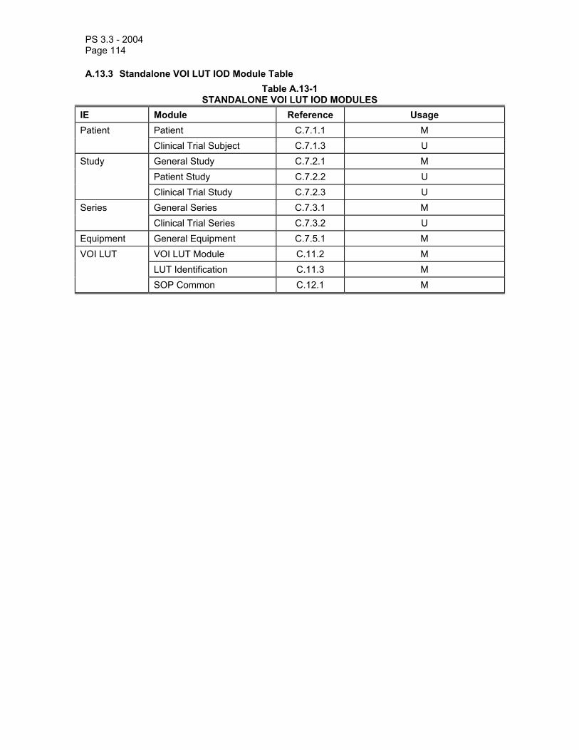
PS 3.3 - 2004 Page 114
A.13.3 Standalone VOI LUT IOD Module Table Table A.13-1
STANDALONE VOI LUT IOD MODULES IE Module Reference Usage Patient Patient C.7.1.1 M Clinical Trial Subject C.7.1.3 U Study General Study C.7.2.1 M Patient Study C.7.2.2 U Clinical Trial Study C.7.2.3 U Series General Series C.7.3.1 M Clinical Trial Series C.7.3.2 U Equipment General Equipment C.7.5.1 M VOI LUT VOI LUT Module C.11.2 M LUT Identification C.11.3 M SOP Common C.12.1 M

PS 3.3 - 2004 Page 115
A.14 X-RAY ANGIOGRAPHIC IMAGE INFORMATION OBJECT DEFINITION
A.14.1 XA Image IOD Description
This Section defines the Information Object for single plane X-Ray Angiographic Imaging that includes those data elements and information objects necessary for the interchange of digital X-Ray Angiographic data. This includes images of the heart and all blood vessels.
The XA IOD share a significant amount of common information with the XRF IOD. The differences between the two IODs are that the XRF Image IOD includes a tomography module; and the two IODs utilize different methods to specify positioner angles. The XRF Image IOD contains a single column angulation Data Element that uses an equipment based coordinate system, while XA Image IOD c-arm positioner angles are specified in a patient based coordinate system. RF applications that support a patient-based coordinate system with cranial/caudal, LAO/RAO angles may utilize the XA IOD.
The XA IOD is also applicable to clinical areas other than angiography (e.g. Interventional Procedures, Myelography, Biopsy/Localization, and Neurology).
Note: 1. For the purpose of X-Ray Angiography (XA), this IOD can be used to encode a single frame image, or a Cine Run encoded in a single multi-frame image.
2. A typical study might include all the images generated between the time a patient gets on and gets off the procedure table. As several separable diagnostic or therapeutic processes may occur during a single study (e.g., pre-intervention CA, left ventriculography, and post-intervention CA), a series may be defined as comprising a set of images (single or Multi-Frame) associated with one such process within a study.
3. This IOD can be used to encode a single plane acquisition, or one plane of a biplane acquisition.
A.14.2 XA Image IOD Entity-Relationship Model
The E-R Model in Section A.1.2 depicts those components of the DICOM Application Information Model that directly reference the X-Ray Angiographic Image IOD, with exception of the Frame of Reference and Modality LUT entities, which are not used. Additionally, "Image" in Figure A.1-1 may represent a Single Frame or a Multi-Frame image. A frame denotes a two-dimensional organization of pixels recorded as a single exposure.

PS 3.3 - 2004 Page 116
A.14.3 XA Image IOD Module Table
Table A.14.-1 X-RAY ANGIOGRAPHIC IMAGE IOD MODULES
IE Module Reference Usage Patient Patient C.7.1.1 M Clinical Trial Subject C.7.1.3 U Study General Study C.7.2.1 M Patient Study C.7.2.2 U Clinical Trial Study C.7.2.3 U Series General Series C.7.3.1 M Clinical Trial Series C.7.3.2 U Frame of Reference
Synchronization C.7.4.2 U
Equipment General Equipment C.7.5.1 M Image General Image C.7.6.1 M Image Pixel C.7.6.3 M Contrast/Bolus C.7.6.4 C - Required if contrast media was
used in this Image Cine C.7.6.5 C - Required if pixel data is Multi-
Frame Cine data Multi-Frame C.7.6.6 C - Required if pixel data is Multi-
Frame Cine data Frame Pointers C.7.6.9 U Mask C.7.6.10 C - Required if the Image may be
subtracted Display Shutter C.7.6.11 U Device C.7.6.12 U Intervention C.7.6.13 U X-Ray Image C.8.7.1 M X-Ray Acquisition C.8.7.2 M X-Ray Collimator C.8.7.3 U X-Ray Table C.8.7.4 C - Required if Image is created
with table motion, may be present otherwise
XA Positioner C.8.7.5 M DX Detector C.8.11.4 U Overlay Plane C.9.2 U Multi-Frame Overlay C.9.3 C - Required if Overlay data
contains multiple frames. Curve C.10.2 U (See C.8.7.1.1.9) Modality LUT C.11.1 C - Required if Pixel Intensity
Relationship (0028,1040) is LOG

PS 3.3 - 2004 Page 117
U - Optional if Pixel Intensity Relationship (0028,1040) is DISP
VOI LUT C.11.2 U SOP Common C.12.1 M
A.15 X-RAY ANGIOGRAPHIC BI-PLANE IMAGE INFORMATION OBJECT DEFINITION (RETIRED)
A.16 X-RAY RF IMAGE INFORMATION OBJECT DEFINITION
A.16.1 XRF Image IOD Description
The focus for this X-Ray RF Image IOD (XRF IOD) is to address the requirements for image transfer found in general Radiofluoroscopic applications performed on a table with a column. For applications performed on X-Ray RF acquisition systems that support a patient based coordinate system with cranial/caudal, LAO/RAO angles, etc. the XA Image IOD may be used.
Note: An example of a case where the XA IOD may be preferred to the RF IOD are RF acquisition system equipped with an X-Ray source and an image Receptor positioned by what is generally called a c-arm (e.g. Interventional Procedures, Myelography, Biopsy, and Neurology).
This Section defines the Information Object for X-Ray Radiofluoroscopic Imaging that includes those data elements and information objects necessary for the interchange of digital X-Ray RF Image data. The XRF IOD is applicable to X-Ray acquisition systems equipped with an image receptor whose plane is parallel to the table plane where the patient is. This Table has in general the ability to be tilted. Furthermore the X-Ray source may be supported by a column that can be angulated to adjust the incidence of the X-Ray beam on the image receptor plan. An equipment based coordinated system is used to track these angles.
Notes: 1. For the purpose of X-Ray Radiofluoroscopy, this IOD can be used to encode a single frame image, or a cine run encoded in a single multi-frame image.
2. A typical study might include all the images generated between the time a patient gets on and gets off the procedure table. As several separable diagnostic or therapeutic processes may occur during a single study, a series may be defined as comprising a set of images (single or Multi-Frame) associated with one such process within a study.
A.16.2 XRF Image IOD Entity-Relationship Model The E-R Model in Section A.1.2 depicts those components of the DICOM Application Information Model that directly reference the X-Ray RF Image IOD, with exception of the Frame of Reference entity that is not used. Additionally, "Image" in figure A.1-1 may represent a Single Frame or a Multi-Frame image. A frame denotes a two-dimensional organization of pixels recorded as a single exposure.
Note: When a Study (or Study Component) contains a number of Multi-frame images that do not need to be grouped under different Series, a single Series may be used with a series number containing an arbitrary value (e.g. 1).
A.16.3 XRF Image IOD Module Table

PS 3.3 - 2004 Page 118
Table A.16-1 - XRF IMAGE IOD MODULES IE Module Reference Usage Patient Patient C.7.1.1 M Clinical Trial Subject C.7.1.3 U Study General Study C.7.2.1 M Patient Study C.7.2.2 U Clinical Trial Study C.7.2.3 U Series General Series C.7.3.1 M Clinical Trial Series C.7.3.2 U Frame of Reference
Synchronization C.7.4.2 U
Equipment General Equipment C.7.5.1 M Image General Image C.7.6.1 M Image Pixel C.7.6.3 M Contrast/bolus C.7.6.4 C - Required if contrast media was
used in this Image Cine C.7.6.5 C - Required if pixel data is Multi-
Frame Cine Data Multi-Frame C.7.6.6 C - Required if pixel data is Multi-
Frame Cine Data Frame Pointers C.7.6.9 U Mask C.7.6.10 C - Required if the Image may be
subtracted X-Ray Image C.8.7.1 M X-Ray Acquisition C.8.7.2 M X-Ray Collimator C.8.7.3
U
Display Shutter C.7.6.11
U
Device C.7.6.12 U Intervention C.7.6.13 U X-Ray Table C.8.7.4 U XRF Positioner C.8.7.6 U X-Ray Tomo Acquisition C.8.7.7 C - Required if Scan Option
(0018,0022) is TOMO DX Detector C.8.11.4 U Overlay Plane C.9.2 U Multi-frame Overlay C.9.3 C - Required if Overlay Data
contains multiple frames Curve C.10.2 U Modality LUT C.11.1 C - Required if Pixel Intensity
Relationship (0028,1040) is LOG
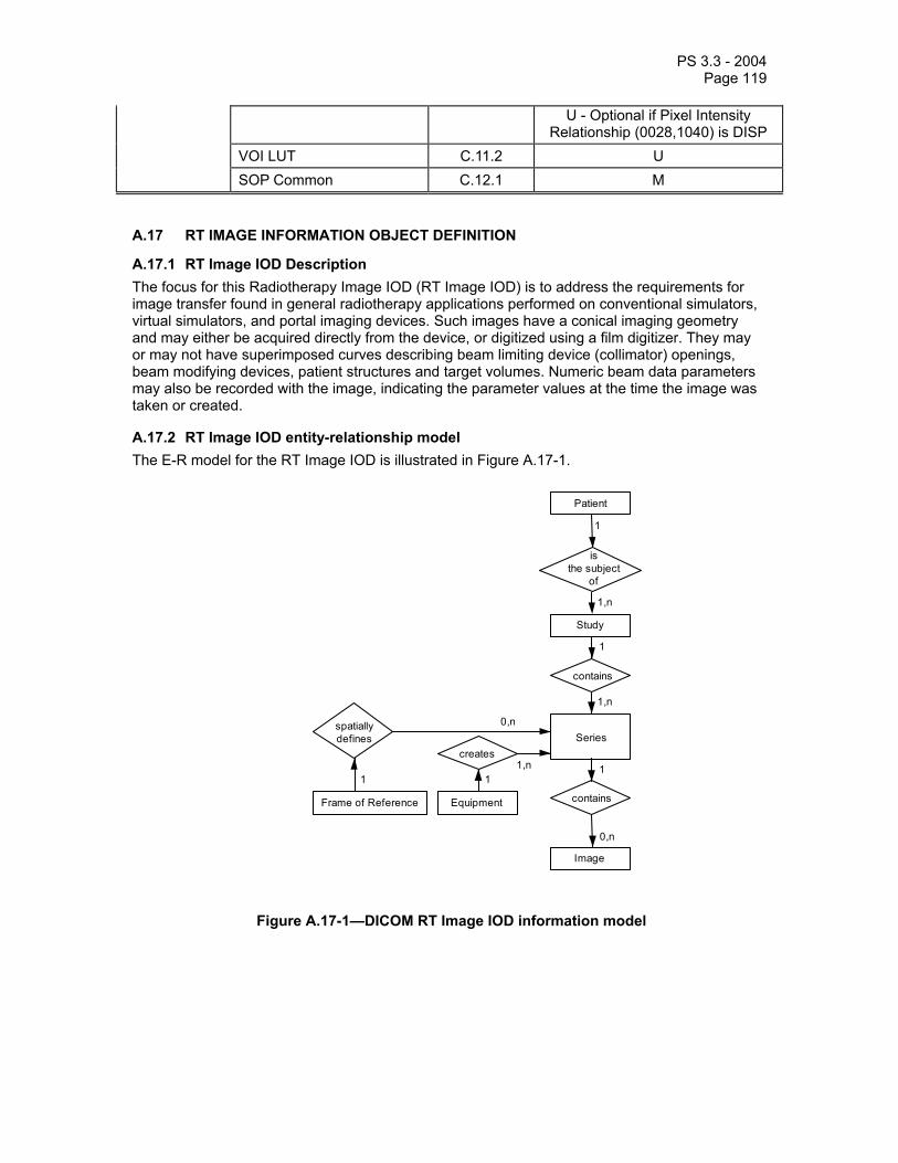
PS 3.3 - 2004 Page 119
U - Optional if Pixel Intensity Relationship (0028,1040) is DISP
VOI LUT C.11.2 U SOP Common C.12.1 M
A.17 RT IMAGE INFORMATION OBJECT DEFINITION
A.17.1 RT Image IOD Description The focus for this Radiotherapy Image IOD (RT Image IOD) is to address the requirements for image transfer found in general radiotherapy applications performed on conventional simulators, virtual simulators, and portal imaging devices. Such images have a conical imaging geometry and may either be acquired directly from the device, or digitized using a film digitizer. They may or may not have superimposed curves describing beam limiting device (collimator) openings, beam modifying devices, patient structures and target volumes. Numeric beam data parameters may also be recorded with the image, indicating the parameter values at the time the image was taken or created.
A.17.2 RT Image IOD entity-relationship model The E-R model for the RT Image IOD is illustrated in Figure A.17-1.
Patient
is the subject
of
1
1
Study
1,n
Series
contains
spatially defines
EquipmentFrame of Reference
creates
111,n
0,n
1,n
contains
1
Image
0,n
Figure A.17-1—DICOM RT Image IOD information model

PS 3.3 - 2004 Page 120
A.17.3 RT Image IOD Module Table Table A.17.3-1—RT IMAGE IOD MODULES
IE Module Reference Usage Patient Patient C.7.1.1 M Clinical Trial Subject C.7.1.3 U Study General Study C.7.2.1 M Patient Study C.7.2.2 U Clinical Trial Study C.7.2.3 U Series RT Series C.8.8.1 M Clinical Trial Series C.7.3.2 U Frame of Reference
Frame of Reference C.7.4.1 U
Equipment General Equipment C.7.5.1 M Image General Image C.7.6.1 M Image Pixel C.7.6.3 M Contrast/bolus C.7.6.4 C-Required if contrast media was
used in this image. Cine C.7.6.5 C - Required if multi-frame image is
a cine image. Multi-Frame C.7.6.6 C - Required if pixel data is multi-
frame data. RT Image C.8.8.2 M Modality LUT C.11.1 U VOI LUT C.11.2 U Approval C.8.8.16 U Curve C.10.2 U Audio C.10.3 U SOP Common C.12.1 M
Notes: 1. The inclusion of the Multi-Frame module allows for the expression of time-dependent image series or multiple exposures of identical beam geometries (i.e. multiple exposure portal images). If a time-dependent series of images (such as port images or DRRs) is represented the Cine module is used to indicate this. This would subsequently allow analysis of patient movement during treatment. Multiple exposure images allow individual images of treatment ports and open field ports to be grouped into a single multi-frame image.
2. The Modality LUT module has been included to allow the possibility of conversion between portal image pixel values and dose transmitted through the patient. The VOI LUT module has been included to allow the possibility of translation between stored pixel values (after the Modality LUT has been applied if specified) and display levels.
3. The Curve module has been included to allow the possibility of storing one or more curves overlaid with a given image. Generally these curves would represent patient structures, target volumes, or beam limiting device (collimator) openings, although they could also be used to store other data such as axis information. Such curves would be stored in pixel units (i.e. the coordinates would represent pixel indices in the image data). For example, patient structures might have the following attribute assignments:

PS 3.3 - 2004 Page 121
Curve Dimensions (50xx,0005) = 2
Number of Points (50xx,0010) = Number of data points in curve
Type of Data (50xx,0020) = ROI
Data Value Representation (50xx,0103) = US (unsigned short)
Curve Data (50xx,3000) = (x,y) pixel coordinates
Curve Description (50xx,0022) = Structure/Target name Note that there is no facility for representing multi-frame curves (i.e. all curves are interpreted as
being related to the first image frame in a multi-frame image). Curves other than patient structures might also be represented using the HIST, POLY or TABL curve types (see C.10.2.1).
4. The Equipment module contains information describing the equipment used to acquire or generate the RT Image (such as a portal imager, conventional simulator or treatment planning system). However, the equipment attributes in the RT Image module describe the equipment on which the treatment has been or will be given, typically an electron accelerator.
5. For RT Images that contain no relevant pixel data, such as BEV images without DRR information, Pixel Data (7FE0,0010) should be filled with a sequence of zeros.
6. The Frame of Reference module has been included to allow the indication of spatial association of two or more RT Image instances (e.g. where the images have been acquired in the same frame of reference, or have been resampled to share the same frame of reference). If the Frame of Reference occurs within a SOP Instance within a given series, then all SOP Instances within that series will be spatially related. For example, two RT Images may share the same Frame of Reference if they are located on the same physical plane, as determined by the treatment machine Gantry Angle (300A,011E) and source to image plane distance specified by RT Image SID (3002,0026).

PS 3.3 - 2004 Page 122
A.18 RT DOSE INFORMATION OBJECT DEFINITION
A.18.1 RT Dose IOD Description The focus for this Radiotherapy Dose IOD (RT Dose IOD) is to address the requirements for transfer of dose distributions calculated by radiotherapy treatment planning systems. These distributions may be represented as 2D or 3D grids, as isodose curves, or as named or unnamed dose points scattered throughout the volume. This IOD may also contain dose-volume histogram data, single or multi-frame overlays, audio annotations, and application-defined lookup tables. This IOD does not provide for definition of doses in beam or other coordinate systems. The application is responsible for transforming data in other, non-patient based coordinate systems to the patient based coordinate system described in C.7.6.2.1.1.
A.18.2 RT Dose IOD entity-relationship model The E-R model for the RT Dose IOD is illustrated in Figure A.18-1.
Patient
is the subject
of
1
1
Study
1,n
Series
contains
spatially defines
EquipmentFrame of Reference
creates
111,n
0,n
1,n
contains
1
Dose
0,n
Figure A.18-1—DICOM RT Dose IOD information model
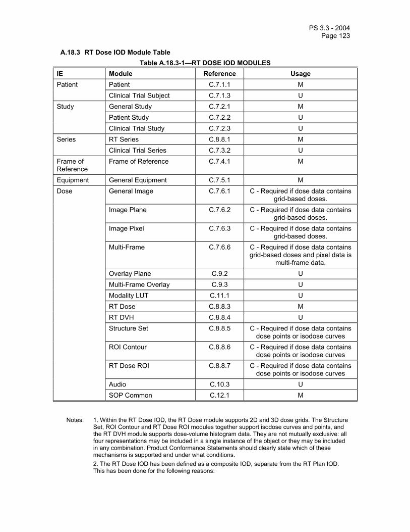
PS 3.3 - 2004 Page 123
A.18.3 RT Dose IOD Module Table Table A.18.3-1—RT DOSE IOD MODULES
IE Module Reference Usage Patient Patient C.7.1.1 M Clinical Trial Subject C.7.1.3 U Study General Study C.7.2.1 M Patient Study C.7.2.2 U Clinical Trial Study C.7.2.3 U Series RT Series C.8.8.1 M Clinical Trial Series C.7.3.2 U Frame of Reference
Frame of Reference C.7.4.1 M
Equipment General Equipment C.7.5.1 M Dose General Image C.7.6.1 C - Required if dose data contains
grid-based doses. Image Plane C.7.6.2 C - Required if dose data contains
grid-based doses. Image Pixel C.7.6.3 C - Required if dose data contains
grid-based doses. Multi-Frame C.7.6.6 C - Required if dose data contains
grid-based doses and pixel data is multi-frame data.
Overlay Plane C.9.2 U Multi-Frame Overlay C.9.3 U Modality LUT C.11.1 U RT Dose C.8.8.3 M RT DVH C.8.8.4 U Structure Set C.8.8.5 C - Required if dose data contains
dose points or isodose curves ROI Contour C.8.8.6 C - Required if dose data contains
dose points or isodose curves RT Dose ROI C.8.8.7 C - Required if dose data contains
dose points or isodose curves Audio C.10.3 U SOP Common C.12.1 M
Notes: 1. Within the RT Dose IOD, the RT Dose module supports 2D and 3D dose grids. The Structure Set, ROI Contour and RT Dose ROI modules together support isodose curves and points, and the RT DVH module supports dose-volume histogram data. They are not mutually exclusive: all four representations may be included in a single instance of the object or they may be included in any combination. Product Conformance Statements should clearly state which of these mechanisms is supported and under what conditions.
2. The RT Dose IOD has been defined as a composite IOD, separate from the RT Plan IOD. This has been done for the following reasons:

PS 3.3 - 2004 Page 124
– to allow for the multiplicity of possible dose calculations using beam models for the same basic plan,
– to avoid undesirable transmission of large amounts of data with the treatment plan, and – to accommodate the fact that CT Simulation and other “beam geometry” generating devices
that use the RT Plan IOD do not have or require access to this data, either for transmission or storage.
A.19 RT STRUCTURE SET INFORMATION OBJECT DEFINITION
A.19.1 RT Structure Set IOD Description The focus for this Radiotherapy Structure Set IOD (RT Structure Set IOD) is to address the requirements for transfer of patient structures and related data defined on CT scanners, virtual simulation workstations, treatment planning systems and similar devices. This IOD may also contain audio curve annotations.
A.19.2 RT Structure Set IOD entity-relationship model The E-R model for the RT Structure Set IOD is illustrated in Figure A.19-1.
Patient
is the subject
of
1
1
Study
1,n
Series
contains
Equipment
creates
11,n
1,n
contains
1
Structure Set
0,n
Figure A.19-1—DICOM RT Structure Set IOD information model

PS 3.3 - 2004 Page 125
A.19.3 RT Structure Set IOD Module Table Table A.19.3-1—RT STRUCTURE SET IOD MODULES
IE Module Reference Usage Patient Patient C.7.1.1 M Clinical Trial Subject C.7.1.3 U Study General Study C.7.2.1 M Patient Study C.7.2.2 U Clinical Trial Study C.7.2.3 U Series RT Series C.8.8.1 M Clinical Trial Series C.7.3.2 U Equipment General Equipment C.7.5.1 M Structure Set Structure Set C.8.8.5 M ROI Contour C.8.8.6 M RT ROI Observations C.8.8.8 M Approval C.8.8.16 U Audio C.10.3 U SOP Common C.12.1 M

PS 3.3 - 2004 Page 126
A.20 RT PLAN INFORMATION OBJECT DEFINITION
A.20.1 RT Plan IOD Description The focus for this Radiotherapy Plan IOD (RT Plan IOD) is to address the requirements for transfer of treatment plans generated by manual entry, a virtual simulation system, or a treatment planning system before or during a course of treatment. Such plans may contain fractionation information, and define external beams and/or brachytherapy application setups. This IOD may also contain audio curve annotations.
A.20.2 RT Plan IOD entity-relationship model The E-R model for the RT Plan IOD is illustrated in Figure A.20-1.
Patient
is the subject
of
1
1
Study
1,n
Series
contains
Equipment
creates
11,n
1,n
contains
1
Plan
0,n
Figure A.20-1—DICOM RT Plan IOD information model

PS 3.3 - 2004 Page 127
A.20.3 RT Plan IOD Module Table Table A.20.3-1—RT PLAN IOD MODULES
IE Module Reference Usage Patient Patient C.7.1.1 M Clinical Trial Subject C.7.1.3 U Study General Study C.7.2.1 M Patient Study C.7.2.2 U Clinical Trial Study C.7.2.3 U Series RT Series C.8.8.1 M Clinical Trial Series C.7.3.2 U Frame of Reference
Frame of Reference C.7.4.1 U – See Note.
Equipment General Equipment C.7.5.1 M Plan RT General Plan C.8.8.9 M RT Prescription C.8.8.10 U RT Tolerance Tables C.8.8.11 U RT Patient Setup C.8.8.12 U RT Fraction Scheme C.8.8.13 U RT Beams C.8.8.14 C - Required if RT Fraction
Scheme Module exists and Number of Beams (300A,0080) is greater than zero for one or more
fraction groups RT Brachy Application
Setups C.8.8.15 C - Required if RT Fraction
Scheme Module exists and Number of Brachy Application
Setups (300A,00A0) is greater than zero for one or more fraction
groups Approval C.8.8.16 U Audio C.10.3 U SOP Common C.12.1 M
Note: The RT Structure Set referenced in Referenced Structure Set Sequence (300C,0060) of the RT General Plan Module may contain more than one item in the Referenced Frame of Reference Sequence (3006,0010) in the Structure Set Module. In this case, it is highly recommended that the Frame of Reference Module be supplied in the RT Plan object, to unambiguously specify the frame of reference of the RT Plan contents.
A.20.3.1 RT FRACTION SCHEME MODULE The RT Fraction Scheme module is structured to be used together with the RT Beams or RT Brachy Application Setups module. If beams are referenced in the RT Fraction Scheme module, all such beams shall be included in the RT Beams module if it is present. Similarly, if brachy application setups are referenced in the RT Fraction Scheme module, all such setups shall be included in the RT Brachy Application Setups module if it is present. However, the RT Fraction

PS 3.3 - 2004 Page 128
Scheme module can be used without the RT Beams or RT Brachy Application Setups modules if no beams or brachy application setups are referenced, and the RT Beams or RT Brachy Application Setups modules can also be used without the RT Fraction Scheme module if no fraction scheme information is available.
A.20.3.2 RT PRESCRIPTION MODULE The RT Prescription module provides for the inclusion of dose prescription information pertinent to the complete plan, which may comprise several fraction schemes, themselves consisting of many beams.
A.20.3.3 RT TOLERANCE TABLES MODULE The RT Tolerance Tables module provides information concerning machine tolerances as they apply to the whole treatment plan. Tolerances are applied by reference to a tolerance table within the RT Tolerance Tables module for beams contained within the RT Beams module.
A.20.3.4 RT PATIENT SETUP MODULE The RT Patient Setup module provides information concerning patient setup parameters and fixation devices as they apply to the whole treatment plan. Patient setup information within the RT Patient Setup module is referenced by beams contained within the RT Beams module.

PS 3.3 - 2004 Page 129
A.21 POSITRON EMISSION TOMOGRAPHY IMAGE INFORMATION OBJECT DEFINITION
A.21.1 PET Image IOD Description The Positron Emission Tomography (PET) Image Information Object Definition specifies an image that has been created by a Positron Tomograph imaging device, including dedicated PET cameras and Nuclear Medicine imaging devices operating in coincidence mode. This includes data created by external detection devices that create images of the distribution of administered radioactive materials, specifically positron emitters, in the body. Depending on the specific radiopharmaceuticals administered and the particular imaging procedure performed, problems involving changes in metabolism, function, or physiology can be investigated and various region pathologies can be studied. For these problems, quantitation of image data in absolute activity and physiological units is important. In addition, the PET Image IOD specifies attenuation (transmission) images used for correction and anatomical reference of emission images.
A.21.2 PET Image IOD Entity-Relationship Model The E-R model in Section A.1.2 of this part depicts those components of the DICOM Information Model that directly reference the PET Image IOD. The overlay IE, modality LUT IE, VOI LUT IE, and curve IE are not components of the PET Image IOD.
A.21.3 PET Image IOD Module Table Table A.21.3-1 - PET IMAGE IOD MODULES
IE Module Reference Usage Patient Patient C.7.1.1 M Clinical Trial Subject C.7.1.3 U Study General Study C.7.2.1 M Patient Study C.7.2.2 U Clinical Trial Study C.7.2.3 U Series General Series C.7.3.1 M Clinical Trial Series C.7.3.2 U PET Series C.8.9.1 M PET Isotope C.8.9.2 M PET Multi-gated Acquisition C.8.9.3 C - Required if Series Type
(0054,1000) Value 1 is GATED. NM/PET Patient Orientation C.8.4.6 M Frame of Reference
Frame of Reference C.7.4.1 M
Equipment General Equipment C.7.5.1 M Image General Image C.7.6.1 M Image Plane C.7.6.2 M Image Pixel C.7.6.3 M PET Image C.8.9.4 M Overlay Plane C.9.2 U VOI LUT C.11.2 U SOP Common C.12.1 M

PS 3.3 - 2004 Page 130
A.22 STANDALONE PET CURVE INFORMATION OBJECT DEFINITION
A.22.1 Standalone PET Curve IOD Description A standalone PET curve IOD is the specification of a PET curve that may be related to an image, but also may have its own existence within a PET Series.
A.22.2 Standalone PET Curve IOD Entity-Relationship Model The E-R model in Section A.1.2 of this part depicts those components of the DICOM Information Model that directly reference the standalone PET curve IOD. The frame of reference IE, overlay IE, modality LUT IE, VOI LUT IE and Image IE are not components of the standalone PET curve IOD.
A.22.3 Standalone PET Curve IOD Module Table Table A.22.3-1 - STANDALONE PET CURVE IOD MODULES
IE Module Reference Usage Patient Patient C.7.1.1 M Clinical Trial Subject C.7.1.3 U Study General Study C.7.2.1 M Patient Study C.7.2.2 U Clinical Trial Study C.7.2.3 U Series General Series C.7.3.1 M Clinical Trial Series C.7.3.2 U PET Series C.8.9.1 M PET Isotope C.8.9.2 M PET Multi-gated Acquisition C.8.9.3 C - Required if Series Type
(0054,1000) Value 1 is GATED. Equipment General Equipment C.7.5.1 M Curve Curve Identification C.10.1 M Curve C.10.2 M PET Curve C.8.9.5 M SOP Common C.12.1 M
A.23 STORED PRINT INFORMATION OBJECT DEFINITION
A.23.1 IOD Description The Stored Print IOD describes all the print parameters to print a single film. The Stored Print IOD contains one or more references to Image SOP Instances. There is a many to one relationship between the Stored Print IOD and the Printer IOD.
Images referenced by the Stored Print IOD shall be Preformatted Grayscale or Preformatted Color Images or other grayscale images where all grayscale transformations up to and including VOI LUT have been applied.

PS 3.3 - 2004 Page 131
A.23.2 Stored Print IOD Entity-Relationship Model The E-R Model in Section A.1.2 depicts those components of the DICOM Information Model that directly reference the Stored Print IOD. The Frame of Reference IE, Overlay IE, Curve IE, VOI LUT IE, and Modality LUT IE are not components of the Stored Print IOD.
A.23.3 IOD Module Table Table A.23-1
STORED PRINT IOD MODULES IE Module Reference Usage Patient Patient C.7.1.1 M Clinical Trial Subject C.7.1.3 U Study General Study C.7.2.1 M Patient Study C.7.2.2 U Clinical Trial Study C.7.2.3 U Series General Series C.7.3.1 M Clinical Trial Series C.7.3.2 U Equipment General Equipment C.7.5.1 M Printer Characteristics C.16.1 M Image Film Box C.16.2 M Image Box List C.16.3 M Annotation List C.16.4 U Image Overlay Box List C.16.5 U Presentation LUT List C.16.6 U SOP Common Information C.12.1 M
A.24 HARDCOPY GRAYSCALE IMAGE INFORMATION OBJECT DEFINITION
A.24.1 IOD Description The Hardcopy Grayscale IOD is an abstraction of a printable 8 or 12 bit grayscale image where annotation, overlays, graphics may be burned in and where the LUT operations up to and including VOI LUT have already been performed.
Notes: 1. A hardcopy grayscale image corresponds with a Preformatted Grayscale Image (see PS 3.4) and is a specialization of the Secondary Capture Image.
2. The optional Annotation List and Image Overlay Box Modules in the Stored Print IOD provide additional overlay, graphic, and annotation information that will be burnt into the printed image only if both the SCU and SCP support the Attributes in these Modules. See the Pull Print Request N-CREATE Behavior Section in PS 3.4.
A.24.2 Hardcopy Grayscale Image IOD Entity-Relationship Model The E-R Model in Section A.1.2 depicts those components of the DICOM Information Model that are related to the Hardcopy Grayscale Image IOD.

PS 3.3 - 2004 Page 132
A.24.3 IOD Module Table Table A.24-1
HARDCOPY GRAYSCALE IMAGE IOD MODULES IE Module Reference Usage Patient Patient C.7.1.1 M Clinical Trial Subject C.7.1.3 U Study General Study C.7.2.1 M Patient Study C.7.2.2 U Clinical Trial Study C.7.2.3 U Series General Series C.7.3.1 M Clinical Trial Series C.7.3.2 U Equipment General Equipment C.7.5.1 U Hardcopy Equipment C.8.10.1 M Image General Image C.7.6.1 M HC Grayscale Image C.8.10.2 M SOP Common Information C.12.1 M
The Overlay Plane Module (C.9.2) was previously in this IOD. Its use in this IOD has been retired. See PS 3.3-1998.
A.25 HARDCOPY COLOR IMAGE INFORMATION OBJECT DEFINITION
A.25.1 IOD Description The Hardcopy Color IOD is an abstraction of a printable 8 bit color image where annotation, overlays, and graphics may be burned in.
Note : A hardcopy color image corresponds with a Preformatted Color Image (see PS 3.4 ) and is a specialization of the Secondary Capture Image.
A.25.2 Hardcopy Color Image IOD Entity-Relationship Model The E-R Model in Section A.1.2 depicts those components of the DICOM Information Model that are related to the Hardcopy Color Image IOD.

PS 3.3 - 2004 Page 133
A.25.3 IOD Module Table Table A.25-1
HARDCOPY COLOR IMAGE IOD MODULES IE Module Reference Usage Patient Patient C.7.1.1 M Clinical Trial Subject C.7.1.3 U Study General Study C.7.2.1 M Patient Study C.7.2.2 U Clinical Trial Study C.7.2.3 U Series General Series C.7.3.1 M Clinical Trial Series C.7.3.2 U Equipment General Equipment C.7.5.1 U Hardcopy Equipment C.8.10.1 M Image General Image C.7.6.1 M HC Color Image C.8.10.3 M SOP Common Information C.12.1 M
The Overlay Plane Module (C.9.2) was previously in this IOD. Its use in this IOD has been retired. See PS 3.3-1998.
A.26 DIGITAL X-RAY IMAGE INFORMATION OBJECT DEFINITION
A.26.1 DX Image IOD Description The Digital X-Ray (DX) Image Information Object Definition specifies an image that has been created by a digital projection radiography imaging device.
Notes: 1. This includes but is not limited to: chest radiography, linear and multi-directional tomography, orthopantomography and skeletal radiography. Acquisition of image data may include but is not limited to: CCD-based sensors, stimulable phosphor imaging plates, amorphous selenium, scintillation based amorphous silicon and secondary capture of film-based images.
2. Specific IODs are defined for intra-oral radiography and mammography that further specialize the DX IOD.
A DX image shall consist of the result of a single X-Ray exposure, in order to ensure that the anatomical and orientation attributes are meaningful for the image, permitting safe annotation, appropriate image processing and appropriate dissemination.
Notes: 1. This requirement specifically deprecates the common film/screen and Computed Radiography practice of making multiple exposures on different areas of a cassette or plate by using lead occlusion between exposures. Such acquisitions could be separated and transformed into multiple DX images during an appropriate quality assurance step by an operator.
2. This requirement does not deprecate the acquisition of multiple paired structures during a single exposure, provided that they can be described by the relevant orientation Attributes. For example, an AP or PA projection of both hands side by side is typically obtained in a single exposure, and can be described by a Patient Orientation (0020,0020) of R\H or L\H since both hands are in the same traditional Anatomical Position. See Annex E.
The DX Image IOD is used in two SOP Classes as defined in PS 3.4 Storage Service Class, a SOP Class for storage of images intended for presentation, and a SOP Class for storage of
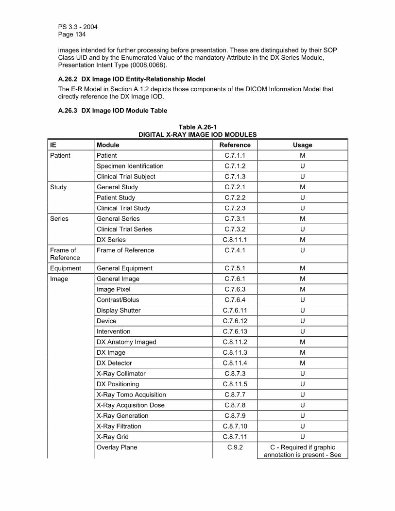
PS 3.3 - 2004 Page 134
images intended for further processing before presentation. These are distinguished by their SOP Class UID and by the Enumerated Value of the mandatory Attribute in the DX Series Module, Presentation Intent Type (0008,0068).
A.26.2 DX Image IOD Entity-Relationship Model The E-R Model in Section A.1.2 depicts those components of the DICOM Information Model that directly reference the DX Image IOD.
A.26.3 DX Image IOD Module Table
Table A.26-1 DIGITAL X-RAY IMAGE IOD MODULES
IE Module Reference Usage Patient Patient C.7.1.1 M Specimen Identification C.7.1.2 U Clinical Trial Subject C.7.1.3 U Study General Study C.7.2.1 M Patient Study C.7.2.2 U Clinical Trial Study C.7.2.3 U Series General Series C.7.3.1 M Clinical Trial Series C.7.3.2 U DX Series C.8.11.1 M Frame of Reference
Frame of Reference C.7.4.1 U
Equipment General Equipment C.7.5.1 M Image General Image C.7.6.1 M Image Pixel C.7.6.3 M Contrast/Bolus C.7.6.4 U Display Shutter C.7.6.11 U Device C.7.6.12 U Intervention C.7.6.13 U DX Anatomy Imaged C.8.11.2 M DX Image C.8.11.3 M DX Detector C.8.11.4 M X-Ray Collimator C.8.7.3 U DX Positioning C.8.11.5 U X-Ray Tomo Acquisition C.8.7.7 U X-Ray Acquisition Dose C.8.7.8 U X-Ray Generation C.8.7.9 U X-Ray Filtration C.8.7.10 U X-Ray Grid C.8.7.11 U Overlay Plane C.9.2 C - Required if graphic
annotation is present - See

PS 3.3 - 2004 Page 135
A.26.4 Curve C.10.2 U VOI LUT C.11.2 C - Required if Presentation
Intent Type (0008,0068) is FOR PRESENTATION. Shall
not be present otherwise. See Note 8.
Image Histogram C.11.5 U Acquisition Context C.7.6.14 M SOP Common C.12.1 M
Notes: 1. The Overlay Plane requirement is determined by the presence of “graphic annotation”. Graphic annotation includes user or machine drawn graphics or text (such as computer assisted diagnosis) to indicate regions of interest or descriptions. It specifically does not include patient or image identification or technique information that is defined in other Attributes of the IOD..
2. The Device and Intervention Modules are User optional, though it is desirable that, if present, they are stored by an SCP. It is recognized that in some cases the digital image acquisition system will not have a user interface or direct connection that allows acquisition of these parameters, even if device or therapy have been used.
3. The Frame of Reference, X-Ray Collimator, DX Positioning and DX Tomo Acquisition Modules are User optional, though it is desirable that, if present, they are stored by an SCP. It is recognized that in some cases the parameters of the mechanical devices used for collimation, positioning and tomography may not be available to a digital image acquisition system that is not integrated with the X-Ray generation and positioning system.
4. The Acquisition Context Module is mandatory, but may include only an empty (zero-length) Acquisition Context Sequence (0040,0555). Thus all Level 1 or 2 Storage SCPs will preserve any information present, and acquisition systems are not required to generate any content in that Sequence
5. Expectations on what an SCP of a SOP Class based on this IOD will store may be determined by evaluating a Conformance Statement of the form defined in PS 3.2 that specifies the level of conformance to the Storage SOP Classes as defined in PS 3.4. For example, Level 2 (Full) conformance indicates that all standard and optional attributes will be stored and may be accessed.
6. The Histogram Module may contain a single or multiple statistical representations of the pixel data used to derive the VOI LUT Module, or intended to be used to derive or replace the VOI LUT Module. The Histogram Module may contain statistics of a subset of the stored image pixel data (such as from a cropped area or region of interest that is not the full field of view) that are useful for deriving a better VOI LUT than might be derived from the statistics obtained from the entire stored pixel data.
7. The Specimen Identification Module is User optional, because although its Attributes may be helpful for identification and correlation with Pathology Information Systems, much specimen radiography, including forensic radiography, is performed with conventional clinical X-Ray equipment that is not likely to support specific specimen identification features.
8. The VOI LUT Module Attributes and behavior are further specialized in the DX Image Module.
A.26.4 Overlay Plane Module If the Overlay Plane Module is present, any Overlays defined in that Module shall store the overlay data in Overlay Data (60xx,3000), and not any unused high bits in Pixel Data (7FE0,0010).

PS 3.3 - 2004 Page 136
A.27 DIGITAL MAMMOGRAPHY X-RAY IMAGE INFORMATION OBJECT DEFINITION
A.27.1 Digital Mammography X-Ray Image IOD Description The Digital Mammography X-Ray Image Information Object Definition specifies an image that has been created by a digital mammography projection radiography imaging device.
Note: It meets all of the requirements of the DX IOD in A.26 in addition to those specified in this section.
The Digital Mammography Image IOD is used in two SOP Classes as defined in PS 3.4 Storage Service Class, a SOP Class for storage of images intended for presentation, and a SOP Class for storage of images intended for further processing before presentation. These are distinguished by their SOP Class UID and by the Enumerated Value of the mandatory Attribute in the DX Series Module, Presentation Intent Type (0008,0068).

PS 3.3 - 2004 Page 137
A.27.2 Digital Mammography X-Ray Image IOD Module Table
Table A.27-1 DIGITAL MAMMOGRAPHY X-RAY IMAGE IOD MODULES
IE Module Reference Usage Patient Patient C.7.1.1 M Specimen Identification C.7.1.2 U Clinical Trial Subject C.7.1.3 U Study General Study C.7.2.1 M Patient Study C.7.2.2 U Clinical Trial Study C.7.2.3 U Series General Series C.7.3.1 M Clinical Trial Series C.7.3.2 U DX Series C.8.11.1 M Mammography Series C.8.11.6 M Frame of Reference
Frame of Reference C.7.4.1 C - Required if multiple images are obtained without
releasing breast compressionEquipment General Equipment C.7.5.1 M Image General Image C.7.6.1 M Image Pixel C.7.6.3 M Contrast/Bolus C.7.6.4 U Display Shutter C.7.6.11 U Device C.7.6.12 U Intervention C.7.6.13 U DX Anatomy Imaged C.8.11.2 M DX Image C.8.11.3 M DX Detector C.8.11.4 M X-Ray Collimator C.8.7.3 U DX Positioning C.8.11.5 U X-Ray Tomo Acquisition C.8.7.7 U X-Ray Acquisition Dose C.8.7.8 U X-Ray Generation C.8.7.9 U X-Ray Filtration C.8.7.10 U X-Ray Grid C.8.7.11 U

PS 3.3 - 2004 Page 138
Mammography Image C.8.11.7 M Overlay Plane C.9.2 C - Required if graphic
annotation is present - See A.27.3
Curve C.10.2 U VOI LUT C.11.2 C - Required if Presentation
Intent Type (0008,0068) is FOR PRESENTATION. Shall
not be present otherwise. Image Histogram C.11.5 U Acquisition Context C.7.6.14 M SOP Common C.12.1 M
A.27.3 Overlay Plane Module If the Overlay Plane Module is present, any Overlays defined in that Module shall store the overlay data in Overlay Data (60xx,3000), and not any unused high bits in Pixel Data (7FE0,0010).
A.28 DIGITAL INTRA-ORAL X-RAY IMAGE INFORMATION OBJECT DEFINITION
A.28.1 Digital Intra-oral X-Ray Image IOD Description The Digital Intra-oral X-Ray Image Information Object Definition specifies an image that has been created by an intra-oral projection radiography imaging device.
Note: It meets all of the requirements of the DX IOD in A.26 in addition to those specified in this section.

PS 3.3 - 2004 Page 139
The Digital Intra-oral X-Ray Image IOD is used in two SOP Classes as defined in PS 3.4 Storage Service Class, a SOP Class for storage of images intended for presentation, and a SOP Class for storage of images intended for further processing before presentation. These are distinguished by their SOP Class UID and by the Enumerated Value of the mandatory Attribute in the DX Series Module, Presentation Intent Type (0008,0068).
A.28.2 Digital Intra-oral X-Ray Image IOD Module Table
Table A.28-1 DIGITAL INTRA-ORAL X-RAY IMAGE IOD MODULES
IE Module Reference Usage Patient Patient C.7.1.1 M Specimen Identification C.7.1.2 U Clinical Trial Subject C.7.1.3 U Study General Study C.7.2.1 M Patient Study C.7.2.2 U Clinical Trial Study C.7.2.3 U Series General Series C.7.3.1 M Clinical Trial Series C.7.3.2 U DX Series C.8.11.1 M Intra-oral Series C.8.11.8 M Frame of Reference
Frame of Reference C.7.4.1 U
Equipment General Equipment C.7.5.1 M Image General Image C.7.6.1 M Image Pixel C.7.6.3 M Contrast/Bolus C.7.6.4 U Display Shutter C.7.6.11 U Device C.7.6.12 U Intervention C.7.6.13 U DX Anatomy Imaged C.8.11.2 M DX Image C.8.11.3 M DX Detector C.8.11.4 M X-Ray Collimator C.8.7.3 U DX Positioning C.8.11.5 U X-Ray Tomo Acquisition C.8.7.7 U X-Ray Acquisition Dose C.8.7.8 U X-Ray Generation C.8.7.9 U X-Ray Filtration C.8.7.10 U X-Ray Grid C.8.7.11 U
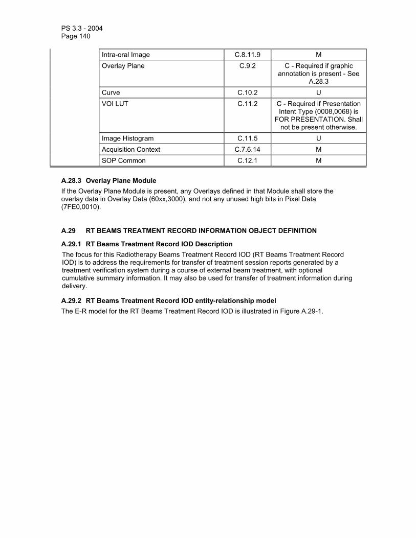
PS 3.3 - 2004 Page 140
Intra-oral Image C.8.11.9 M Overlay Plane C.9.2 C - Required if graphic
annotation is present - See A.28.3
Curve C.10.2 U VOI LUT C.11.2 C - Required if Presentation
Intent Type (0008,0068) is FOR PRESENTATION. Shall
not be present otherwise. Image Histogram C.11.5 U Acquisition Context C.7.6.14 M SOP Common C.12.1 M
A.28.3 Overlay Plane Module If the Overlay Plane Module is present, any Overlays defined in that Module shall store the overlay data in Overlay Data (60xx,3000), and not any unused high bits in Pixel Data (7FE0,0010).
A.29 RT BEAMS TREATMENT RECORD INFORMATION OBJECT DEFINITION
A.29.1 RT Beams Treatment Record IOD Description The focus for this Radiotherapy Beams Treatment Record IOD (RT Beams Treatment Record IOD) is to address the requirements for transfer of treatment session reports generated by a treatment verification system during a course of external beam treatment, with optional cumulative summary information. It may also be used for transfer of treatment information during delivery.
A.29.2 RT Beams Treatment Record IOD entity-relationship model The E-R model for the RT Beams Treatment Record IOD is illustrated in Figure A.29-1.

PS 3.3 - 2004 Page 141
Patient
is the subject
of
1
1
Study
1,n
Series
contains
Equipment
creates
11,n
1,n
contains
1
RT Beams Treatment Record
0,n
Figure A.29-1—DICOM RT Beams Treatment Record IOD information model

PS 3.3 - 2004 Page 142
A.29.3 RT Beams Treatment Record IOD Module Table Table A.29.3-1—RT Beams Treatment Record IOD Modules
IE Module Reference Usage Patient Patient C.7.1.1 M Clinical Trial Subject C.7.1.3 U Study General Study C.7.2.1 M Patient Study C.7.2.2 U Clinical Trial Study C.7.2.3 U Series RT Series C.8.8.1 M Clinical Trial Series C.7.3.2 U Equipment General Equipment C.7.5.1 M Treatment Record
RT General Treatment Record
C.8.8.17 M
RT Patient Setup C.8.8.12 U RT Treatment Machine
Record C.8.8.18 M
Measured Dose Reference Record
C.8.8.19 U
Calculated Dose Reference Record
C.8.8.20 U
RT Beams Session Record C.8.8.21 M RT Treatment Summary
Record C.8.8.23 U
Curve C.10.2 U SOP Common C.12.1 M
A.30 RT BRACHY TREATMENT RECORD INFORMATION OBJECT DEFINITION
A.30.1 RT Brachy Treatment Record IOD Description The focus for this Radiotherapy Brachy Treatment Record IOD (RT Brachy Treatment Record IOD) is to address the requirements for transfer of treatment session reports generated by a treatment verification system during a course of Brachytherapy treatment, with optional cumulative summary information. It may also be used for transfer of treatment information during delivery.
A.30.2 RT Brachy Treatment Record IOD entity-relationship model The E-R model for the RT Brachy Treatment Record IOD is illustrated in Figure A.30-1.

PS 3.3 - 2004 Page 143
Patient
is the subject
of
1
1
Study
1,n
Series
contains
Equipment
creates
11,n
1,n
contains
1
RT Brachy Treatment Record
0,n
Figure A.30-1—DICOM RT Brachy Treatment Record IOD information model
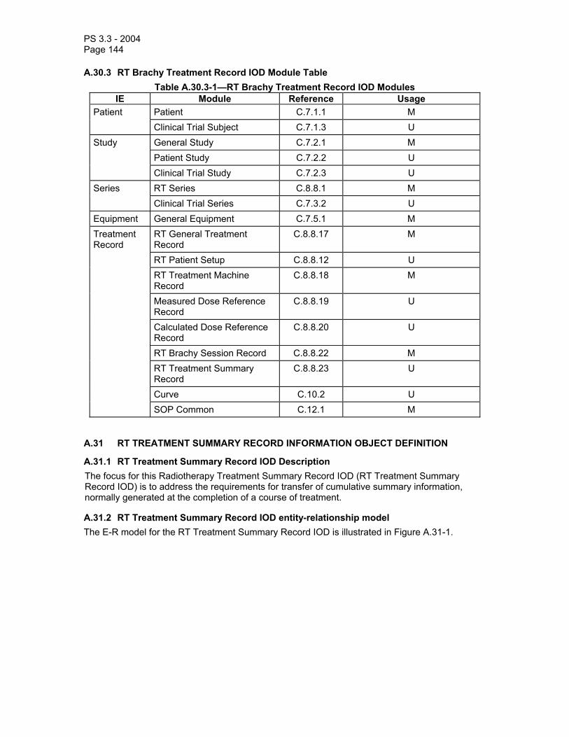
PS 3.3 - 2004 Page 144
A.30.3 RT Brachy Treatment Record IOD Module Table Table A.30.3-1—RT Brachy Treatment Record IOD Modules
IE Module Reference Usage Patient Patient C.7.1.1 M Clinical Trial Subject C.7.1.3 U Study General Study C.7.2.1 M Patient Study C.7.2.2 U Clinical Trial Study C.7.2.3 U Series RT Series C.8.8.1 M Clinical Trial Series C.7.3.2 U Equipment General Equipment C.7.5.1 M Treatment Record
RT General Treatment Record
C.8.8.17 M
RT Patient Setup C.8.8.12 U RT Treatment Machine
Record C.8.8.18 M
Measured Dose Reference Record
C.8.8.19 U
Calculated Dose Reference Record
C.8.8.20 U
RT Brachy Session Record C.8.8.22 M RT Treatment Summary
Record C.8.8.23 U
Curve C.10.2 U SOP Common C.12.1 M
A.31 RT TREATMENT SUMMARY RECORD INFORMATION OBJECT DEFINITION
A.31.1 RT Treatment Summary Record IOD Description The focus for this Radiotherapy Treatment Summary Record IOD (RT Treatment Summary Record IOD) is to address the requirements for transfer of cumulative summary information, normally generated at the completion of a course of treatment.
A.31.2 RT Treatment Summary Record IOD entity-relationship model The E-R model for the RT Treatment Summary Record IOD is illustrated in Figure A.31-1.

PS 3.3 - 2004 Page 145
Patient
is the subject
of
1
1
Study
1,n
Series
contains
Equipment
creates
11,n
1,n
contains
1
RT Treatment Summary Record
0,n
Figure A.31-1—DICOM RT Treatment Summary Record IOD information model
A.31.3 RT Treatment Summary Record IOD Module Table Table A.31.3-1—RT Treatment Summary Record IOD Modules
IE Module Reference Usage Patient Patient C.7.1.1 M Clinical Trial Subject C.7.1.3 U Study General Study C.7.2.1 M Patient Study C.7.2.2 U Clinical Trial Study C.7.2.3 U Series RT Series C.8.8.1 M Clinical Trial Series C.7.3.2 U Equipment General Equipment C.7.5.1 M Treatment Record
RT General Treatment Record
C.8.8.17 M
RT Treatment Summary Record
C.8.8.23 M
Curve C.10.2 U SOP Common C.12.1 M
A.32 VISIBLE LIGHT IMAGE INFORMATION OBJECT DEFINITIONS
The Visible Light (VL) Image Information Object Definition (IOD) specifies images that are acquired by means of a camera or other sensors that are sensitive to visible or near-visible light.

PS 3.3 - 2004 Page 146
Examples of types of equipment that create Visible Light Images include:
a. Rigid and flexible endoscopy equipment b. Operation microscopes / colposcopes c. Ophthalmology equipment d. Digital or Video Cameras e. Analysis microscopes
Separate IODs have been defined for specialized applications. Some support only single frame images, some support both single frame and multi-frame video images.
A.32.1 VL Endoscopic Image Information Object Definition A.32.1.1 VL Endoscopic Image IOD Description The VL Endoscopic Image IOD specifies the Attributes of Single-frame VL Endoscopic Images.
A.32.1.2 VL Endoscopic Image IOD Entity-Relationship Model The E-R Model in Section A.1.2 of this Part depicts those components of the DICOM Information Model that directly reference the VL Endoscopic Image IOD, with exception of the Curve, VOI LUT, Frame of Reference and Modality LUT entities, which are not used. Additionally, Image in figure A.1.2 of PS3.3 represents a Single Frame image. A frame denotes a two-dimensional organization of pixels recorded as a single exposure. Table A.32.1-1 specifies the Modules of the VL Endoscopic Image IOD.
Notes: 1. An endoscopic procedure might include multiple series of single frame endoscopic images as well as one or more additional series of related diagnostic images. The procedure might involve multiple Performed Procedure Steps, multiple endoscopes, and multiple anatomic regions and might be supervised, performed, and/or interpreted by one or more individuals. 2. Several distinct diagnostic or therapeutic processes might occur during an endoscopic procedure. For example: Endoscopic examination of duodenal mucosa, biopsy, lavage, or biliary stone removal.
Table A.32.1-1 VL ENDOSCOPIC IMAGE IOD MODULES
IE Module Reference Usage Patient Patient C.7.1.1 M Clinical Trial Subject C.7.1.3 U Study General Study C.7.2.1 M Patient Study C.7.2.2 U Clinical Trial Study C.7.2.3 U Series General Series C.7.3.1 M Clinical Trial Series C.7.3.2 U Equipment General Equipment C.7.5.1 M Image General Image C.7.6.1 M Image Pixel C.7.6.3 M Acquisition Context C.7.6.14 M VL Image C.8.12.1 M Overlay Plane C.9.2 U SOP Common C.12.1 M

PS 3.3 - 2004 Page 147
A.32.1.3 VL Endoscopic Image IOD Content Constraints A.32.1.3.1 Modality The value of Modality (0008,0060) shall be ES.
A.32.2 VL Microscopic Image Information Object Definition A.32.2.1 VL Microscopic Image IOD Description The VL Microscopic Image IOD specifies the Attributes of Single-frame VL Microscopic Images. Slide Coordinates shall not be encoded with this IOD.
A.32.2.2 VL Microscopic Image IOD Entity-Relationship Model The E-R Model in Section A.1.2 of this Part depicts those components of the DICOM Information Model that directly reference the VL Microscopic Image IOD, with exception of the Curve, VOI LUT, Frame of Reference and Modality LUT entities, which are not used. Additionally, Image in figure A.1.2 of PS3.3 represents a Single Frame image. A frame denotes a two-dimensional organization of pixels recorded as a single exposure. Table A.32.1-2 specifies the Modules of the VL Microscopic Image IOD.
Notes: 1. A microscopy procedure might include multiple series of single frame VL Microscopic Images as well as one or more additional series of related diagnostic images. The procedure might involve multiple Performed Procedure Steps, multiple microscopes, and multiple anatomic regions and might be supervised, performed, and/or interpreted by one or more individuals. 2. Several distinct diagnostic or therapeutic processes might occur during a single procedure. For example: Histologic staining of the same section with multiple special stains.
Table A.32.1-2 VL MICROSCOPIC IMAGE IOD MODULES
IE Module Reference Usage Patient Patient C.7.1.1 M Specimen
Identification C.7.1.2 M
Clinical Trial Subject
C.7.1.3 U
Study General Study C.7.2.1 M Patient Study C.7.2.2 U Clinical Trial Study C.7.2.3 U Series General Series C.7.3.1 M Clinical Trial Series C.7.3.2 U Equipment General Equipment C.7.5.1 M Image General Image C.7.6.1 M Image Pixel C.7.6.3 M Acquisition Context C.7.6.14 M VL Image C.8.12.1 M Overlay Plane C.9.2 U SOP Common C.12.1 M

PS 3.3 - 2004 Page 148
A.32.2.3 VL Microscopic Image IOD Content Constraints A.32.2.3.1 Modality The value of Modality (0008,0060) shall be GM.
A.32.3 VL Slide-Coordinates Microscopic Image Information Object Definition A.32.3.1 VL Slide-Coordinates Microscopic Image IOD Description The VL Slide-Coordinates Microscopic Image IOD specifies the Attributes of VL Single-frame Slide-Coordinates Microscopic Images.
A.32.3.2 VL Slide-Coordinates Microscopic Image IOD Entity-Relationship Model The E-R Model in Section A.1.2 of this Part depicts those components of the DICOM Information Model that directly reference the VL Slide-Coordinates Microscopic Image IOD, with exception of the Curve, VOI LUT, Frame of Reference and Modality LUT entities, which are not used. Additionally, Image in figure A.1.2 of PS3.3 represents a Single Frame image. A frame denotes a two-dimensional organization of pixels recorded as a single exposure. Table A.32.1-3 specifies the Modules of the VL Slide-Coordinates Microscopic Image IOD.
Notes: 1. A microscopic imaging procedure might include multiple series of single frame Microscopic Images as well as one or more additional series of related diagnostic images and might involve multiple Performed Procedure Steps, multiple Microscopes, and multiple anatomic regions. The procedure might be supervised, performed, and/or interpreted by one or more individuals. 2. Several distinct diagnostic or therapeutic processes might occur during a single procedure. For example: Histologic staining of the same section with multiple special stains.
Table A.32.1-3 VL SLIDE-COORDINATES MICROSCOPIC IMAGE IOD MODULES
IE Module Reference Usage Patient Patient C.7.1.1 M Specimen
Identification C.7.1.2 M
Clinical Trial Subject C.7.1.3 U Study General Study C.7.2.1 M Patient Study C.7.2.2 U Clinical Trial Study C.7.2.3 U Series General Series C.7.3.1 M Clinical Trial Series C.7.3.2 U Frame of Reference C.7.4.1 M Equipment General Equipment C.7.5.1 M Image General Image C.7.6.1 M Image Pixel C.7.6.3 M Acquisition Context C.7.6.14 M VL Image C.8.12.1 M Slide Coordinates C.8.12.2 M Overlay Plane C.9.2 U SOP Common C.12.1 M

PS 3.3 - 2004 Page 149
A.32.3.3 VL Slide-Coordinates Microscopic Image IOD Content Constraints A.32.3.3.1 Modality The value of Modality (0008,0060) shall be SM.
A.32.4 VL Photographic Image Information Object Definition A.32.4.1 VL Photographic Image IOD Description The VL Photographic Image IOD specifies the attributes of VL Single-frame photographic Images.
A.32.4.2 VL Photographic Image IOD Entity-Relationship Model The E-R Model in Section A.1.2 of this Part depicts those components of the DICOM Information Model that directly reference the VL Photographic Image IOD, with exception of the Curve, VOI LUT, Frame of Reference and Modality LUT entities, which are not used. Additionally, Image in figure A.1.2 of PS3.3 represents a Single Frame image. A frame denotes a two-dimensional organization of pixels recorded as a single exposure. Table A.32.4-1 specifies the Modules of the VL Photographic Image IOD.
Notes: 1. A VL photographic imaging procedure might include multiple series of single frame VL Photographic images as well as one or more additional series of related diagnostic images. The procedure might involve multiple Performed Procedure Steps, multiple cameras, and multiple anatomic regions and might be supervised, performed, and/or interpreted by one or more individuals. 2. Several distinct diagnostic or therapeutic processes might occur during a single procedure.
Table A.32.4-1 VL PHOTOGRAPHIC IMAGE IOD MODULES
IE Module Reference Usage Patient Patient C.7.1.1 M Specimen
Identification C.7.1.2 C - Required if the Imaging Subject is a Specimen
Clinical Trial Subject C.7.1.3 U Study General Study C.7.2.1 M Patient Study C.7.2.2 U Clinical Trial Study C.7.2.3 U Series General Series C.7.3.1 M Clinical Trial Series C.7.3.2 U Equipment General Equipment C.7.5.1 M Image General Image C.7.6.1 M Image Pixel C.7.6.3 M Acquisition Context C.7.6.14 M VL Image C.8.12.1 M Overlay Plane C.9.2 U SOP Common C.12.1 M

PS 3.3 - 2004 Page 150
A.32.4.3 VL Photographic Image IOD Content Constraints A.32.4.3.1 Modality The value of Modality (0008,0060) shall be XC.
A.32.5 Video Endoscopic Image Information Object Definition A.32.5.1 Video Endoscopic Image IOD Description The Video Endoscopic Image IOD specifies the Attributes of Multi-frame Video Endoscopic Images.
A.32.5.2 Video Endoscopic Image IOD Entity-Relationship Model The E-R Model in Section A.1.2 of this Part depicts those components of the DICOM Information Model that directly reference the Video Endoscopic Image IOD, with exception of the Curve, VOI LUT, and Modality LUT entities, which are not used. Table A.32.5-1 specifies the Modules of the Video Endoscopic Image IOD.
Notes: 1. An endoscopic procedure might include multiple series of video Endoscopic images as well as one or more additional series of: single frame VL Endoscopic images, Key Object Selection documents (for selecting clips from the video) and/or of related diagnostic images. The procedure might involve multiple Performed Procedure Steps, multiple endoscopes, and multiple anatomic regions and might be supervised, performed, and/or interpreted by one or more individuals. 2. Several distinct diagnostic or therapeutic processes might occur during an endoscopic procedure. For example: Endoscopic examination of duodenal mucosa, biopsy, lavage, or biliary stone removal. 3. The video may include audio channel(s) for acquiring patient voice or physiological sounds, healthcare professionals' commentary, or environmental sounds. 4. The Frame Pointers Module has not been included because the selection of relevant sub-sequence(s) is usually made in a second workflow step and stored into separate Key Object Selection Documents.
Table A.32.5-1 VIDEO ENDOSCOPIC IMAGE IOD MODULES
IE Module Reference Usage Patient Patient C.7.1.1 M Clinical Trial Subject C.7.1.3 U Study General Study C.7.2.1 M Patient Study C.7.2.2 U Clinical Trial Study C.7.2.3 U Series General Series C.7.3.1 M Clinical Trial Series C.7.3.2 U Equipment General Equipment C.7.5.1 M Image General Image C.7.6.1 M Cine C.7.6.5 M Multi-frame C.7.6.6 M Image Pixel C.7.6.3 M Acquisition Context C.7.6.14 M VL Image C.8.12.1 M
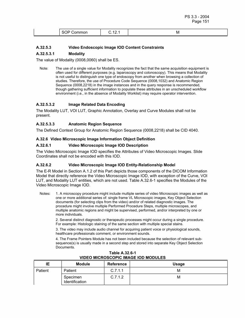
PS 3.3 - 2004 Page 151
SOP Common C.12.1 M
A.32.5.3 Video Endoscopic Image IOD Content Constraints A.32.5.3.1 Modality The value of Modality (0008,0060) shall be ES.
Note: The use of a single value for Modality recognizes the fact that the same acquisition equipment is often used for different purposes (e.g. laparoscopy and colonoscopy). This means that Modality is not useful to distinguish one type of endoscopy from another when browsing a collection of studies. Therefore, the use of Procedure Code Sequence (0008,1032) and Anatomic Region Sequence (0008,2218) in the image instances and in the query response is recommended, though gathering sufficient information to populate these attributes in an unscheduled workflow environment (i.e., in the absence of Modality Worklist) may require operator intervention.
A.32.5.3.2 Image Related Data Encoding The Modality LUT, VOI LUT, Graphic Annotation, Overlay and Curve Modules shall not be present.
A.32.5.3.3 Anatomic Region Sequence The Defined Context Group for Anatomic Region Sequence (0008,2218) shall be CID 4040.
A.32.6 Video Microscopic Image Information Object Definition A.32.6.1 Video Microscopic Image IOD Description The Video Microscopic Image IOD specifies the Attributes of Video Microscopic Images. Slide Coordinates shall not be encoded with this IOD.
A.32.6.2 Video Microscopic Image IOD Entity-Relationship Model The E-R Model in Section A.1.2 of this Part depicts those components of the DICOM Information Model that directly reference the Video Microscopic Image IOD, with exception of the Curve, VOI LUT, and Modality LUT entities, which are not used. Table A.32.6-1 specifies the Modules of the Video Microscopic Image IOD.
Notes: 1. A microscopy procedure might include multiple series of video Microscopic images as well as one or more additional series of: single frame VL Microscopic images, Key Object Selection documents (for selecting clips from the video) and/or of related diagnostic images. The procedure might involve multiple Performed Procedure Steps, multiple microscopes, and multiple anatomic regions and might be supervised, performed, and/or interpreted by one or more individuals. 2. Several distinct diagnostic or therapeutic processes might occur during a single procedure. For example: Histologic staining of the same section with multiple special stains. 3. The video may include audio channel for acquiring patient voice or physiological sounds, healthcare professionals comment, or environment sounds. 4. The Frame Pointers Module has not been included because the selection of relevant sub-sequence(s) is usually made in a second step and stored into separate Key Object Selection Documents.
Table A.32.6-1 VIDEO MICROSCOPIC IMAGE IOD MODULES
IE Module Reference Usage Patient Patient C.7.1.1 M Specimen
Identification C.7.1.2 M

PS 3.3 - 2004 Page 152
Clinical Trial Subject C.7.1.3 U Study General Study C.7.2.1 M Patient Study C.7.2.2 U Clinical Trial Study C.7.2.3 U Series General Series C.7.3.1 M Clinical Trial Series C.7.3.2 U Equipment General Equipment C.7.5.1 M Image General Image C.7.6.1 M Cine C.7.6.5 M Multi-frame C.7.6.6 M Image Pixel C.7.6.3 M Acquisition Context C.7.6.14 M VL Image C.8.12.1 M SOP Common C.12.1 M
A.32.6.3 Video Microscopic Image IOD Content Constraints A.32.6.3.1 Modality The value of Modality (0008,0060) shall be GM.
A.32.6.3.2 Image Related Data Encoding The Modality LUT, VOI LUT, Graphic Annotation, Overlay and Curve Modules shall not be present.
A.32.7 Video Photographic Image Information Object Definition A.32.7.1 Video Photographic Image IOD Description The Video Photographic Image IOD specifies the attributes of VL Multi-frame photographic Images.
A.32.7.2 Video Photographic Image IOD Entity-Relationship Model The E-R Model in Section A.1.2 of this Part depicts those components of the DICOM Information Model that directly reference the Video Photographic Image IOD, with exception of the Curve, VOI LUT and Modality LUT entities, which are not used. Table A.32.7-1 specifies the Modules of the Video Photographic Image IOD.
Notes: 1. A VL photographic imaging procedure might include multiple series of video Photographic images as well as one or more additional series of: single frame VL Photographic images, Key Object Selection documents (for selecting clips from the video) and/or of related diagnostic images. The procedure might involve multiple Performed Procedure Steps, multiple cameras, and multiple anatomic regions and might be supervised, performed, and/or interpreted by one or more individuals. 2. Several distinct diagnostic or therapeutic processes might occur during a single procedure. 3. The video may include audio channel for acquiring patient voice or physiological sounds, healthcare professionals comment, or environment sounds. 4. The Frame Pointers Module has not been included because the selection of relevant sub-sequence(s) is usually made in a second step and stored into separate Key Object Selection Documents.

PS 3.3 - 2004 Page 153
Table A.32.7-1 VL PHOTOGRAPHIC IMAGE IOD MODULES
IE Module Reference Usage Patient Patient C.7.1.1 M Specimen
Identification C.7.1.2 C - Required if the Imaging Subject is a Specimen
Clinical Trial Subject C.7.1.3 U Study General Study C.7.2.1 M Patient Study C.7.2.2 U Clinical Trial Study C.7.2.3 U Series General Series C.7.3.1 M Clinical Trial Series C.7.3.2 U Equipment General Equipment C.7.5.1 M Image General Image C.7.6.1 M Cine C.7.6.5 M Multi-frame C.7.6.6 M Image Pixel C.7.6.3 M Acquisition Context C.7.6.14 M VL Image C.8.12.1 M SOP Common C.12.1 M
A.32.7.3 Video Photographic Image IOD Content Constraints A.32.7.3.1 Modality The value of Modality (0008,0060) shall be XC.
A.32.7.3.2 Image Related Data Encoding The Modality LUT, VOI LUT, Graphic Annotation, Overlay and Curve Modules shall not be present.
PS 3.3 - 2004 Page 154
A.33 GRAYSCALE SOFTCOPY PRESENTATION STATE INFORMATION OBJECT DEFINITION
A.33.1 Grayscale Softcopy Presentation State IOD Description
The Grayscale Softcopy Presentation State Information Object Definition (IOD) specifies information that may be used to present (display) images that are referenced from within the IOD.
It includes capabilities for specifying:
a. the output grayscale space in P-Values b. grayscale contrast transformations including modality and VOI LUT c. mask subtraction for multi-frame images d. selection of the area of the image to display and whether to rotate or flip it e. image and display relative annotations, including graphics, text and overlays

PS 3.3 - 2004 Page 155
A.33.2 Grayscale Softcopy Presentation State IOD Module Table
Table A.33-1 Grayscale Softcopy Presentation State IOD MODULES
IE Module Reference Usage Patient Patient C.7.1.1 M Clinical Trial Subject C.7.1.3 U Study General Study C.7.2.1 M Patient Study C.7.2.2 U Clinical Trial Study C.7.2.3 U Series General Series C.7.3.1 M Clinical Trial Series C.7.3.2 U Presentation Series C.11.9 M Equipment General Equipment C.7.5.1 M Presentation Presentation State C.11.10 M State Mask C.7.6.10 C - Required if the referenced
image(s) are multi-frame and are to be subtracted
Display Shutter C.7.6.11 C - Required if a Display Shutter is to be applied to
referenced image(s) and the Bitmap Display Shutter Module is not present
Bitmap Display Shutter C.7.6.15 C - Required if a Display Shutter is to be applied to
referenced image(s) and the Display Shutter Module is not
present Overlay Plane C.9.2 C - Required if Overlay is to
be applied to referenced image(s) or the Bitmap
Display Shutter Module is present
Overlay/Curve Activation C.11.7 C- Required if referenced image contains curve or overlay data that is to be
displayed Displayed Area C.10.4 M Graphic Annotation C.10.5 C - Required if Graphic
Annotations are to be applied to referenced image(s)
Spatial Transformation C.10.6 C - Required if rotation or flipping are to be applied to
referenced image(s) Graphic Layer C.10.7 C - Required if Graphic
Annotations or Overlays or Curves are to be applied to

PS 3.3 - 2004 Page 156
referenced image(s) Modality LUT C.11.1 C - Required if a Modality
LUT is to be applied to referenced image(s)
Softcopy VOI LUT C.11.8 C - Required if a VOI LUT is to be applied to referenced
image(s) Softcopy Presentation LUT C.11.6 M SOP Common C.12.1 M
In the Grayscale Softcopy Presentation State IOD, the Presentation Series Module specializes some Attributes of the General Series Module, and the Presentation State Module specializes some Attributes of the Mask and Display Shutter Modules.
Notes: 1. Subtraction between different images is not supported. 2. The Mask Module condition implies that it need not be supported by an SCP that supports
presentation states only for single frame image storage SOP Classes, or instances of multi-frame image Storage SOP Classes that contain only one frame.
3. The Display Shutter may be used to darken image areas that surround important information and exclude extraneous bright areas that increase glare and ambient lighting impairing image interpretation. For example, unexposed areas in a CR image might be obscured using the Display Shutter, rather than permanently replacing image pixels in those areas.
4. This IOD does not support the storage of a multi-frame overlay in the IOD itself, but does support selective activation of multi-frame overlays within the referenced images via the Overlay/Curve Activation Module.
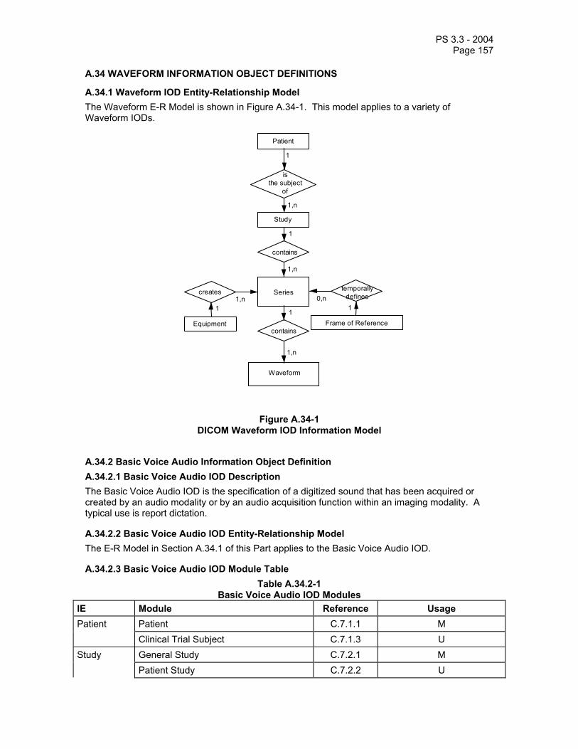
PS 3.3 - 2004 Page 157
A.34 WAVEFORM INFORMATION OBJECT DEFINITIONS
A.34.1 Waveform IOD Entity-Relationship Model The Waveform E-R Model is shown in Figure A.34-1. This model applies to a variety of Waveform IODs.
Patient
is the subject
of
1
1
Study
1,n
Series
contains
Equipment
creates
11,n
1,n
contains
1
Waveform
1,n
Frame of Reference
temporally defines 1
0,n
Figure A.34-1 DICOM Waveform IOD Information Model
A.34.2 Basic Voice Audio Information Object Definition A.34.2.1 Basic Voice Audio IOD Description The Basic Voice Audio IOD is the specification of a digitized sound that has been acquired or created by an audio modality or by an audio acquisition function within an imaging modality. A typical use is report dictation.
A.34.2.2 Basic Voice Audio IOD Entity-Relationship Model The E-R Model in Section A.34.1 of this Part applies to the Basic Voice Audio IOD.
A.34.2.3 Basic Voice Audio IOD Module Table Table A.34.2-1
Basic Voice Audio IOD Modules IE Module Reference Usage Patient Patient C.7.1.1 M Clinical Trial Subject C.7.1.3 U Study General Study C.7.2.1 M Patient Study C.7.2.2 U

PS 3.3 - 2004 Page 158
Clinical Trial Study C.7.2.3 U Series General Series C.7.3.1 M Clinical Trial Series C.7.3.2 U Frame of Reference
Synchronization C.7.4.2 U
Equipment General Equipment C.7.5.1 M Waveform Waveform Identification C.10.8 M Waveform C.10.9 M Acquisition Context C.7.6.14 M Waveform Annotation C.10.10 U SOP Common C.12.1 M
A.34.2.4 Basic Voice Audio IOD Content Constraints A.34.2.4.1 Modality The value of Modality (0008,0060) shall be AU.
A.34.2.4.2 Waveform Sequence The number of Waveform Sequence (5400,0100) Items shall be one.
A.34.2.4.3 Number of Waveform Channels The value of the Number of Waveform Channels (003A,0005) in the Waveform Sequence Item shall be 1 or 2.
A.34.2.4.4 Sampling Frequency The value of the Sampling Frequency (003A,001A) in the Waveform Sequence Item shall be 8000.
A.34.2.4.5 Waveform Sample Interpretation The value of the Waveform Sample Interpretation (5400,1006) in the Waveform Sequence Item shall be UB, MB, or AB.
A.34.3 12-Lead Electrocardiogram Information Object Definition A.34.3.1 12-Lead ECG IOD Description The 12-Lead Electrocardiogram (12-Lead ECG) IOD is the specification of digitized electrical signals from the patient cardiac conduction system collected on the body surface, which has been acquired by an ECG modality or by an ECG acquisition function within an imaging modality.
A.34.3.2 12-Lead ECG IOD Entity-Relationship Model The E-R Model in Section A.34.1 of this Part applies to the 12-Lead ECG IOD.
A.34.3.3 12-Lead ECG IOD Module Table Table A.34.3-1
12-Lead ECG IOD Modules IE Module Reference Usage Patient Patient C.7.1.1 M Clinical Trial Subject C.7.1.3 U

PS 3.3 - 2004 Page 159
Study General Study C.7.2.1 M Patient Study C.7.2.2 U Clinical Trial Study C.7.2.3 U Series General Series C.7.3.1 M Clinical Trial Series C.7.3.2 U Frame of Reference
Synchronization C.7.4.2 U
Equipment General Equipment C.7.5.1 M Waveform Waveform Identification C.10.8 M Waveform C.10.9 M Acquisition Context C.7.6.14 M Waveform Annotation C.10.10 C – required if annotation is
present SOP Common C.12.1 M
A.34.3.4 12-Lead ECG IOD Content Constraints A.34.3.4.1 Modality The value of Modality (0008,0060) shall be ECG.
A.34.3.4.2 Acquisition Context Module For SOP Instances of ECG acquired in the cardiac catheterization lab, the Defined Template for Acquisition Context Sequence (0040,0555) is TID 3403. For routine resting or stress ECG, the Defined Template for Acquisition Context Sequence (0040,0555) is TID 3401.
A.34.3.4.3 Waveform Sequence The number of Waveform Sequence (5400,0100) Items shall be between 1 and 5, inclusive.
A.34.3.4.4 Number of Waveform Channels The value of the Number of Waveform Channels (003A,0005) in each Waveform Sequence Item shall be between 1 and 13, inclusive. The total number of channels encoded across all Items shall not exceed 13.
Note: This specialization provides for up to five Waveform Sequence Items (multiplex groups), with a total of 13 channels. This allows, for instance, encoding of four sets of three simultaneously recorded channels, the sets being acquired sequentially, plus one continuous channel for the duration of the other sets. This can be used to emulate the behavior of classical 12-lead ECG strip chart recorders with 4x3 presentation, plus a continuous lead II recording (see figure).

PS 3.3 - 2004 Page 160
Multiplex Group 1 – leads I, II, III; time offset 0; duration 2.5 s
Multiplex Group 2 – leads aVR, aVL, aVF; time offset 2.5 s; duration 2.5 s Multiplex Group 3 – leads V1, V2, V3; time offset 5.0 s; duration 2.5 s Multiplex Group 4 – leads V4, V5, V6; time offset 7.5 s; duration 2.5 s Multiplex Group 5 – lead II; time offset 0; duration 9.84 s
FIGURE A.34.3-1 12-Lead ECG Example (Informative)
A.34.3.4.5 Number of Waveform Samples The value of the Number of Waveform Samples (003A,0010) in each Waveform Sequence Item shall be less than or equal to 16384.
Note: This allows over 16 seconds per channel at the maximum sampling frequency; if longer recordings are required, the General ECG IOD may be used.
A.34.3.4.6 Sampling Frequency The value of the Sampling Frequency (003A,001A) in each Waveform Sequence Item shall be between 200 and 1000, inclusive.
A.34.3.4.7 Channel Source The Baseline Context ID for the Channel Source Sequence (003A,0208) in each Channel Definition Sequence Item shall be CID 3001.
A.34.3.4.8 Waveform Sample Interpretation The value of the Waveform Sample Interpretation (5400,1006) in each Waveform Sequence Item shall be SS.
A.34.3.4.9 Waveform Annotation Module The Defined Context ID for the Concept Name Code Sequence (0040,A043) in the Waveform Annotation Sequence (0040,B020) shall be CID 3335. This Context Group supports the annotation of suppressed pacemaker spikes in the ECG waveform.

PS 3.3 - 2004 Page 161
A.34.4 General Electrocardiogram Information Object Definition A.34.4.1 General ECG IOD Description The General Electrocardiogram (ECG) IOD is the specification of digitized electrical signals from the patient cardiac conduction system collected on the body surface, which has been acquired by an ECG modality or by an ECG acquisition function within an imaging modality.
A.34.4.2 General ECG IOD Entity-Relationship Model The E-R Model in Section A.34.1 of this Part applies to the General ECG IOD.
A.34.4.3 General ECG IOD Module Table Table A.34.4-1
General ECG IOD Modules IE Module Reference Usage Patient Patient C.7.1.1 M Clinical Trial Subject C.7.1.3 U Study General Study C.7.2.1 M Patient Study C.7.2.2 U Clinical Trial Study C.7.2.3 U Series General Series C.7.3.1 M Clinical Trial Series C.7.3.2 U Frame of Reference
Synchronization C.7.4.2 U
Equipment General Equipment C.7.5.1 M Waveform Waveform Identification C.10.8 M Waveform C.10.9 M Acquisition Context C.7.6.14 M Waveform Annotation C.10.10 C – required if annotation is
present SOP Common C.12.1 M
A.34.4.4 General ECG IOD Content Constraints A.34.4.4.1 Modality The value of Modality (0008,0060) shall be ECG.
A.34.4.4.2 Waveform Sequence The number of Waveform Sequence (5400,0100) Items shall be between 1 and 4, inclusive.
A.34.4.4.3 Number of Waveform Channels The value of the Number of Waveform Channels (003A,0005) in each Waveform Sequence Item shall be between 1 and 24, inclusive.
A.34.4.4.4 Sampling Frequency The value of the Sampling Frequency (003A,001A) in each Waveform Sequence Item shall be between 200 and 1000, inclusive.

PS 3.3 - 2004 Page 162
A.34.4.4.5 Channel Source The Defined Context ID for the Channel Source Sequence (003A,0208) in each Channel Definition Sequence Item shall be CID 3001.
Note: Terms from other Context Groups may also be used for extended specification of the Channel Source, as declared in the Conformance Statement for an application (see PS3.2).
A.34.4.4.6 Waveform Sample Interpretation The value of the Waveform Sample Interpretation (5400,1006) in each Waveform Sequence Item shall be SS.
A.34.4.4.7 Waveform Annotation Module The Defined Context ID for the Concept Name Code Sequence (0040,A043) in the Waveform Annotation Sequence (0040,B020) shall be CID 3335. This Context Group supports the annotation of suppressed pacemaker spikes in the ECG waveform.
A.34.5 Ambulatory Electrocardiogram Information Object Definition A.34.5.1 Ambulatory ECG IOD Description The Ambulatory Electrocardiogram (ECG) IOD is the specification of digitized electrical signals from the patient cardiac conduction system collected on the body surface, which has been acquired by an ambulatory electrocardiography (Holter) device.
Note: The duration of acquisition represented in one SOP Instance is not specifically constrained, and is limited only by the maximum size of the Waveform Data attribute.
A.34.5.2 Ambulatory ECG IOD Entity-Relationship Model The E-R Model in Section A.34.1 of this Part applies to the Ambulatory ECG IOD.
A.34.5.3 Ambulatory ECG IOD Module Table Table A.34.5-1
Ambulatory ECG IOD Modules IE Module Reference Usage Patient Patient C.7.1.1 M Clinical Trial Subject C.7.1.3 U Study General Study C.7.2.1 M Patient Study C.7.2.2 U Clinical Trial Study C.7.2.3 U Series General Series C.7.3.1 M Clinical Trial Series C.7.3.2 U Frame of Reference
Synchronization C.7.4.2 U
Equipment General Equipment C.7.5.1 M Waveform Waveform Identification C.10.8 M Waveform C.10.9 M Acquisition Context C.7.6.14 U Waveform Annotation C.10.10 C – required if annotation is
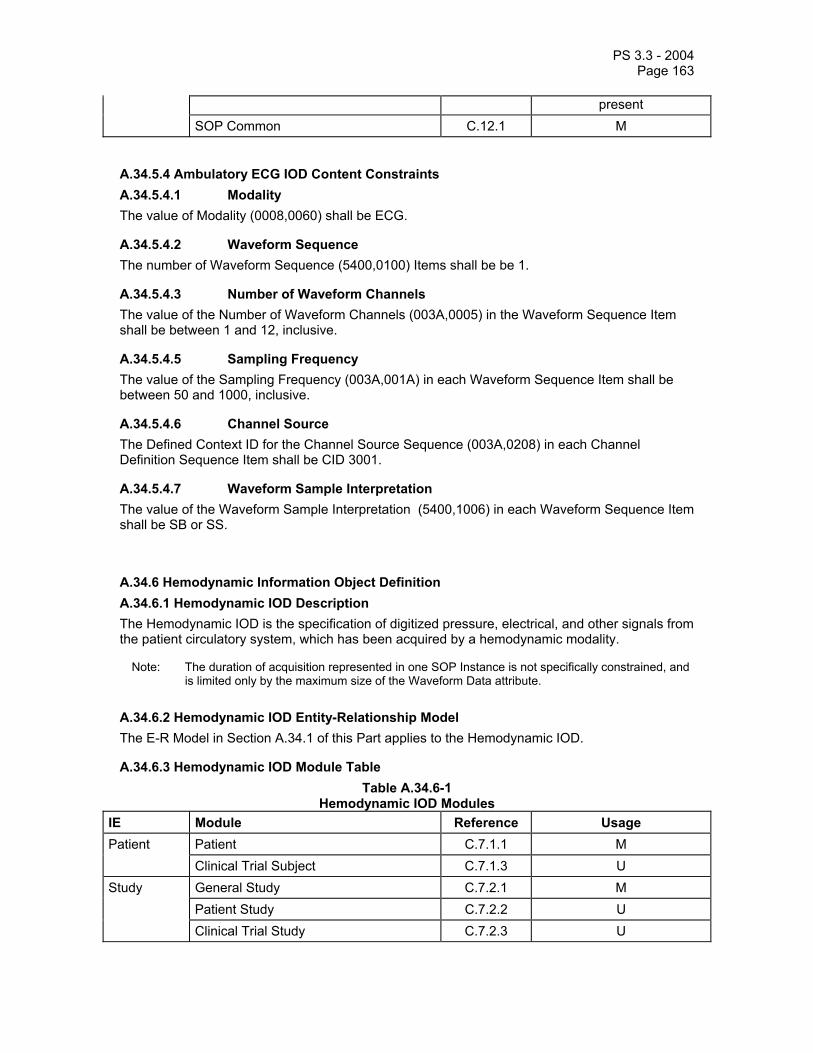
PS 3.3 - 2004 Page 163
present SOP Common C.12.1 M
A.34.5.4 Ambulatory ECG IOD Content Constraints A.34.5.4.1 Modality The value of Modality (0008,0060) shall be ECG.
A.34.5.4.2 Waveform Sequence The number of Waveform Sequence (5400,0100) Items shall be be 1.
A.34.5.4.3 Number of Waveform Channels The value of the Number of Waveform Channels (003A,0005) in the Waveform Sequence Item shall be between 1 and 12, inclusive.
A.34.5.4.5 Sampling Frequency The value of the Sampling Frequency (003A,001A) in each Waveform Sequence Item shall be between 50 and 1000, inclusive.
A.34.5.4.6 Channel Source The Defined Context ID for the Channel Source Sequence (003A,0208) in each Channel Definition Sequence Item shall be CID 3001.
A.34.5.4.7 Waveform Sample Interpretation The value of the Waveform Sample Interpretation (5400,1006) in each Waveform Sequence Item shall be SB or SS.
A.34.6 Hemodynamic Information Object Definition A.34.6.1 Hemodynamic IOD Description The Hemodynamic IOD is the specification of digitized pressure, electrical, and other signals from the patient circulatory system, which has been acquired by a hemodynamic modality.
Note: The duration of acquisition represented in one SOP Instance is not specifically constrained, and is limited only by the maximum size of the Waveform Data attribute.
A.34.6.2 Hemodynamic IOD Entity-Relationship Model The E-R Model in Section A.34.1 of this Part applies to the Hemodynamic IOD.
A.34.6.3 Hemodynamic IOD Module Table Table A.34.6-1
Hemodynamic IOD Modules IE Module Reference Usage Patient Patient C.7.1.1 M Clinical Trial Subject C.7.1.3 U Study General Study C.7.2.1 M Patient Study C.7.2.2 U Clinical Trial Study C.7.2.3 U

PS 3.3 - 2004 Page 164
Series General Series C.7.3.1 M Clinical Trial Series C.7.3.2 U Frame of Reference
Synchronization C.7.4.2 C – Required if Waveform Originality (003A,0004) is
ORIGINAL; may be present otherwise
Equipment General Equipment C.7.5.1 M Waveform Waveform Identification C.10.8 M Waveform C.10.9 M Acquisition Context C.7.6.14 M Waveform Annotation C.10.10 C – required if annotation is
present SOP Common C.12.1 M
A.34.6.4 Hemodynamic IOD Content Constraints A.34.6.4.1 Modality The value of Modality (0008,0060) shall be HD.
A.34.6.4.2 Acquisition Context Module The Defined Template for Acquisition Context Sequence (0040,0555) is TID 3403.
A.34.6.4.3 Waveform Sequence The number of Waveform Sequence (5400,0100) Items shall be between 1 and 4, inclusive.
A.34.6.4.4 Number of Waveform Channels The value of the Number of Waveform Channels (003A,0005) in each Waveform Sequence Item shall be between 1 and 8, inclusive.
A.34.6.4.5 Sampling Frequency The value of the Sampling Frequency (003A,001A) in each Waveform Sequence Item shall be less than or equal to 400.
A.34.6.4.7 Channel Source The Defined Context ID for the Channel Source Sequence (003A,0208) in each Channel Definition Sequence Item shall be CID 3003, CID 3001 for surface ECG channels, or CID 3090 for time synchronization channels. The Channel Source Code Value shall encode at minimum the metric (measured physical quality) and function (measurement or stimulus); unless otherwise specifically encoded, the default function shall be “measurement”.
The Channel Source Modifiers Sequence (003A,0209) in each Channel Definition Sequence Item shall be used to specify additional qualifiers of the semantics of the waveform source, including technique and anatomic location, if not encoded by the Channel Source Code Value. Technique, with terms from Defined Context ID 3241, shall be specified in Channel Source Modifiers Sequence Items prior to the cardiac anatomic location(s), with terms from Defined Context ID 3010, 3014, and 3019. If technique is pullback, the sequence of anatomic locations shall be specified in ordered Channel Source Modifiers Sequence Items (e.g., initial, transitional, and final locations).
Note: Terms from other Context Groups may also be used for extended specification of the Channel Source, as declared in the Conformance Statement for an application (see PS3.2).

PS 3.3 - 2004 Page 165
A.34.6.4.8 Waveform Sample Interpretation The value of the Waveform Sample Interpretation (5400,1006) in each Waveform Sequence Item shall be SS.
A.34.6.4.9 Waveform Annotation Module The Defined Context ID for the Concept Name Code Sequence (0040,A043) in the Waveform Annotation Sequence (0040,B020) shall be CID 3337.
A.34.7 Basic Cardiac Electrophysiology Information Object Definition A.34.7.1 Basic Cardiac EP IOD Description The Basic Cardiac Electrophysiology IOD is the specification of digitized electrical signals from the patient cardiac conduction system collected in the heart, which has been acquired by an EP modality.
Note: The duration of acquisition represented in one SOP Instance is not specifically constrained, and is limited only by the maximum size of the Waveform Data attribute.
A.34.7.2 Basic Cardiac EP IOD Entity-Relationship Model The E-R Model in Section A.34.1 of this Part applies to the Cardiac EP IOD.
A.34.7.3 Basic Cardiac EP IOD Module Table Table A.34.7-1
Basic Cardiac EP IOD Modules IE Module Reference Usage Patient Patient C.7.1.1 M Clinical Trial Subject C.7.1.3 U Study General Study C.7.2.1 M Patient Study C.7.2.2 U Clinical Trial Study C.7.2.3 U Series General Series C.7.3.1 M Clinical Trial Series C.7.3.2 U Frame of Reference
Synchronization C.7.4.2 C – Required if Waveform Originality (003A,0004)
value is ORIGINAL; may be present otherwise
Equipment General Equipment C.7.5.1 M Waveform Waveform Identification C.10.8 M Waveform C.10.9 M Acquisition Context C.7.6.14 M Waveform Annotation C.10.10 C – required if annotation is
present SOP Common C.12.1 M

PS 3.3 - 2004 Page 166
A.34.7.4 Basic Cardiac EP IOD Content Constraints A.34.7.4.1 Modality The value of Modality (0008,0060) shall be EPS.
A.34.7.4.2 Acquisition Context Module The Defined Template for Acquisition Context Sequence (0040,0555) is TID 3450.
A.34.7.4.3 Waveform Sequence The number of Waveform Sequence (5400,0100) Items shall be between 1 and 4, inclusive.
A.34.7.4.4 Sampling Frequency The value of the Sampling Frequency (003A,001A) in each Waveform Sequence Item shall be less than or equal to 2000.
A.34.7.4.5 Channel Source The Defined Context ID for the Channel Source Sequence (003A,0208) in each Channel Definition Sequence Item shall be CID 3011. The Channel Source Code Value shall encode at minimum the anatomic location of the channel source.
The Channel Source Modifiers Sequence (003A,0209) in each Channel Definition Sequence Item shall be used to specify additional qualifiers of the semantics of the waveform source, including metric (measured physical quality), function (measurement or stimulus), and technique from Defined Context ID 3240, and anatomic location qualifiers from Defined Context ID 3019, if not encoded by the Channel Source Code Value. If not explicitly encoded, the default metric and function shall be “voltage measurement”. If a differential signal is used, that shall be indicated in a Modifier Item, and the positive pole and negative pole identified in the subsequent two modifiers.
Notes: 1. Terms from other Context Groups may also be used for extended specification of the Channel Source, as declared in the Conformance Statement for an application (see PS3.2).
2. A differential signal from the high right atrium , where electrode 1 on the catheter is the positive pole and electrode 3 the negative pole, could be specified by coded terms meaning: Channel Source: “High Right Atrium” Channel Source Modifiers: “Differential”, “E1”, “E3” (Implicit default modifier: “Voltage Measurement”)
A.34.7.4.6 Waveform Sample Interpretation The value of the Waveform Sample Interpretation (5400,1006) in each Waveform Sequence Item shall be SS.
A.34.7.4.7 Waveform Annotation Module The Defined Context ID for the Concept Name Code Sequence (0040,A043) in the Waveform Annotation Sequence (0040,B020) shall be CID 3339.

PS 3.3 - 2004 Page 167
A.35 STRUCTURED REPORT DOCUMENT INFORMATION OBJECT DEFINITIONS
A.35.1 Basic Text SR Information Object Definition A.35.1.1 Basic Text SR Information Object Description The Basic Text Structured Report (SR) IOD is intended for the representation of reports with minimal usage of coded entries (typically used in Document Title and headings) and a hierarchical tree of headings under which may appear text and subheadings. Reference to SOP Instances (e.g. images or waveforms or other SR Documents) is restricted to appear at the level of the leaves of this primarily textual tree. This structure simplifies the encoding of conventional textual reports as SR Documents, as well as their rendering.
A.35.1.2 Basic Text SR IOD Entity-Relationship Model The E-R Model in Section A.1.2 of this Part applies to the Basic Text SR IOD. The Frame of Reference IE, and the IEs at the level of the Image IE in Section A.1.2 are not components of the Basic Text SR IOD. Table A.35.1-1 specifies the Modules of the Basic Text SR IOD.
A.35.1.3 Basic Text SR IOD Module Table Table A.35.3-1 specifies the Modules of the Basic Text SR IOD.
Table A.35.1-1 BASIC TEXT SR IOD MODULES
IE Module Reference Usage Patient Patient C.7.1.1 M Specimen Identification C.7.1.2 C - Required if the Observation Subject is a
Specimen Clinical Trial Subject C.7.1.3 U Study General Study C.7.2.1 M Patient Study C.7.2.2 U Clinical Trial Study C.7.2.3 U Series SR Document Series C.17.1 M Clinical Trial Series C.7.3.2 U Equipment General Equipment C.7.5.1 M Document SR Document General C.17.2 M SR Document Content C.17.3 M SOP Common C.12.1 M
A.35.1.3.1 Basic Text SR IOD Content Constraints A.35.1.3.1.1 Value Type Value Type (0040,A040) in the Content Sequence (0040,A730) of the SR Document Content Module is constrained to the following Enumerated Values (see Table C.17.3-7 for Value Type definitions):
TEXT CODE DATETIME DATE TIME UIDREF

PS 3.3 - 2004 Page 168
PNAME COMPOSITE IMAGE WAVEFORM CONTAINER
A.35.1.3.1.2 Relationship Constraints Relationships between Content Items in the content of this IOD shall be conveyed in the by-value mode. See Table C.17.3-8 for Relationship Type definitions.
Note: Relationships by-reference are forbidden. Therefore, Referenced Content Item Identifier (0040,DB73) is not present in any of the Content Items within the SR Document Content Module.
Table A.35.1-2 specifies the relationship constraints of this IOD.
Table A.35.1-2 RELATIONSHIP CONTENT CONSTRAINTS FOR BASIC TEXT SR IOD
Source Value Type Relationship Type (Enumerated Values)
Target Value Type
CONTAINER CONTAINS TEXT, CODE, DATETIME, DATE, TIME, UIDREF, PNAME, COMPOSITE1, IMAGE1, WAVEFORM1, CONTAINER
CONTAINER HAS OBS CONTEXT TEXT, CODE, DATETIME, DATE, TIME, UIDREF, PNAME, COMPOSITE1
CONTAINER, IMAGE1, WAVEFORM1, COMPOSITE1
HAS ACQ CONTEXT TEXT, CODE, DATETIME, DATE, TIME, UIDREF, PNAME
any type HAS CONCEPT MOD TEXT, CODE2
TEXT HAS PROPERTIES TEXT, CODE, DATETIME, DATE, TIME, UIDREF, PNAME, IMAGE1, WAVEFORM1, COMPOSITE1
TEXT INFERRED FROM TEXT, CODE, DATETIME, DATE, TIME, UIDREF, PNAME, IMAGE1, WAVEFORM1, COMPOSITE1
Note: 1. Which SOP Classes the IMAGE, WAVEFORM or COMPOSITE Value Type may refer to, is documented in the Conformance Statement for an application (see PS 3.2 and PS 3.4).
2. The HAS CONCEPT MOD relationship is used to modify the meaning of the Concept Name of a Source Content Item, for example to provide a more descriptive explanation, a different language translation, or to define a post-coordinated concept.
A.35.2 Enhanced SR Information Object Definition A.35.2.1 Enhanced SR Information Object Description The Enhanced Structured Report (SR) IOD is a superset of the Basic Text SR IOD. It is also intended for the representation of reports with minimal usage of coded entries (typically Document Title and headings) and a hierarchical tree of headings under which may appear text and subheadings. In addition, it supports the use of numeric measurements with coded measurement names and units. Reference to SOP Instances (e.g. images or waveforms or SR

PS 3.3 - 2004 Page 169
Documents) is restricted to appear at the level of the leaves of this primarily textual tree. It enhances references to SOP Instances with spatial regions of interest (points, lines, circle, ellipse, etc.) and temporal regions of interest.
A.35.2.2 Enhanced SR IOD Entity-Relationship Model The E-R Model in Section A.1.2 of this Part applies to the Enhanced SR IOD. The Frame of Reference IE, and the IEs at the level of the Image IE in Section A.1.2 are not components of the Enhanced SR IOD. Table A.35.2-1 specifies the Modules of the Enhanced SR IOD.
A.35.2.3 Enhanced SR IOD Module Table Table A.35.2-1
ENHANCED SR IOD MODULES IE Module Reference Usage Patient Patient C.7.1.1 M Specimen Identification C.7.1.2 C - Required if the Observation Subject is a
Specimen Clinical Trial Subject C.7.1.3 U Study General Study C.7.2.1 M Patient Study C.7.2.2 U Clinical Trial Study C.7.2.3 U Series SR Document Series C.17.1 M Clinical Trial Series C.7.3.2 U Equipment General Equipment C.7.5.1 M Document SR Document General C.17.2 M SR Document Content C.17.3 M SOP Common C.12.1 M
A.35.2.3.1 Enhanced SR IOD Content Constraints A.35.2.3.1.1 Value Type Value Type (0040,A040) in the Content Sequence (0040,A730) of the SR Document Content Module is constrained to the following Enumerated Values (see Table C.17.3-7 for Value Type definitions):
TEXT CODE NUM DATETIME DATE TIME UIDREF PNAME
SCOORD TCOORD COMPOSITE IMAGE WAVEFORM CONTAINER

PS 3.3 - 2004 Page 170
A.35.2.3.1.2 Relationship Constraints Relationships between Content Items in the content of this IOD shall be conveyed in the by-value mode. See Table C.17.3-8 for Relationship Type definitions.
Note: Relationships by-reference are forbidden. Therefore, Referenced Content Item Identifier (0040,DB73) is not present in any of the Content Items within the SR Document Content Module.
Table A.35.2-2 specifies the relationship constraints of this IOD.
Table A.35.2-2 RELATIONSHIP CONTENT CONSTRAINTS FOR ENHANCED SR IOD
Source Value Type Relationship Type (Enumerated Values)
Target Value Type
CONTAINER CONTAINS TEXT, CODE, NUM, DATETIME, DATE, TIME, UIDREF, PNAME, SCOORD, TCOORD, COMPOSITE1, IMAGE1, WAVEFORM1, CONTAINER
CONTAINER HAS OBS CONTEXT TEXT, CODE, NUM, DATETIME, DATE, TIME, UIDREF, PNAME, COMPOSITE1
CONTAINER, IMAGE1, WAVEFORM1, COMPOSITE1
HAS ACQ CONTEXT TEXT, CODE, NUM, DATETIME, DATE, TIME, UIDREF, PNAME
any type HAS CONCEPT MOD TEXT, CODE2
TEXT, CODE, NUM HAS PROPERTIES TEXT, CODE, NUM, DATETIME, DATE, TIME, UIDREF, PNAME, IMAGE1, WAVEFORM1, COMPOSITE1, SCOORD, TCOORD
TEXT, CODE, NUM INFERRED FROM TEXT, CODE, NUM, DATETIME, DATE, TIME, UIDREF, PNAME, IMAGE1, WAVEFORM1, COMPOSITE1, SCOORD, TCOORD
SCOORD SELECTED FROM IMAGE1
TCOORD SELECTED FROM SCOORD, IMAGE1, WAVEFORM1
Note: 1. Which SOP Classes the IMAGE, WAVEFORM or COMPOSITE Value Type may refer to, is documented in the Conformance Statement for an application (see PS 3.2 and PS 3.4).
2. The HAS CONCEPT MOD relationship is used to modify the meaning of the Concept Name of a Source Content Item, for example to provide a more descriptive explanation, a different language translation, or to define a post-coordinated concept.
A.35.3 Comprehensive SR Information Object Definition A.35.3.1 Comprehensive SR Information Object Description The Comprehensive SR IOD is a superset of the Basic Text SR IOD and the Enhanced SR IOD, which specifies a class of documents, the content of which may include textual and a variety of coded information, numeric measurement values, references to the SOP Instances and spatial or temporal regions of interest within such SOP Instances. Relationships by-reference are enabled between Content Items.

PS 3.3 - 2004 Page 171
A.35.3.2 Comprehensive SR IOD Entity-Relationship Model The E-R Model in Section A.1.2 of this Part applies to the Comprehensive SR IOD. The IEs at the level of the Image IE in Section A.1.2 are not components of the Comprehensive SR IOD. Table A.35.3-1 specifies the Modules of the Comprehensive SR IOD.
A.35.3.3 Comprehensive SR IOD Module Table Table A.35.3-1
COMPREHENSIVE SR IOD MODULES IE Module Reference Usage Patient Patient C.7.1.1 M Specimen Identification C.7.1.2 C - Required if the Observation Subject is a
Specimen Clinical Trial Subject C.7.1.3 U Study General Study C.7.2.1 M Patient Study C.7.2.2 U Clinical Trial Study C.7.2.3 U Series SR Document Series C.17.1 M Clinical Trial Series C.7.3.2 U
Frame of Reference C.7.4.1 U Frame of Reference Synchronization C.7.4.2 U Equipment General Equipment C.7.5.1 M Document SR Document General C.17.2 M SR Document Content C.17.3 M SOP Common C.12.1 M
A.35.3.3.1 Comprehensive SR IOD Content Constraints A.35.3.3.1.1 Value Type Value Type (0040,A040) in the Content Sequence (0040,A730) of the SR Document Content Module is constrained to the following Enumerated Values (see Table C.17.3-7 for Value Type definitions):
TEXT CODE NUM DATETIME DATE TIME UIDREF PNAME
SCOORD TCOORD COMPOSITE IMAGE WAVEFORM CONTAINER

PS 3.3 - 2004 Page 172
A.35.3.3.1.2 Relationship Constraints Relationships between content items in the content of this IOD may be conveyed either by-value or by-reference. Table A.35.3-2 specifies the relationship constraints of this IOD. See Table C.17.3-8 for Relationship Type definitions.
Table A.35.3-2 RELATIONSHIP CONTENT CONSTRAINTS FOR COMPREHENSIVE SR IOD
Source Value Type Relationship Type (Enumerated Values)
Target Value Type
CONTAINER CONTAINS TEXT, CODE, NUM, DATETIME, DATE, TIME, UIDREF, PNAME, SCOORD, TCOORD, COMPOSITE1, IMAGE1, WAVEFORM1, CONTAINER (See below).
TEXT, CODE, NUM, CONTAINER
HAS OBS CONTEXT TEXT, CODE, NUM, DATETIME, DATE, TIME, UIDREF, PNAME, COMPOSITE1
CONTAINER, IMAGE1, WAVEFORM1, COMPOSITE1
HAS ACQ CONTEXT TEXT, CODE, NUM, DATETIME, DATE, TIME, UIDREF, PNAME, CONTAINER.
any type HAS CONCEPT MOD TEXT, CODE2
TEXT, CODE, NUM HAS PROPERTIES TEXT, CODE, NUM, DATETIME, DATE, TIME, UIDREF, PNAME, IMAGE1, WAVEFORM1, COMPOSITE1, SCOORD, TCOORD, CONTAINER.
TEXT, CODE, NUM INFERRED FROM TEXT, CODE, NUM, DATETIME, DATE, TIME, UIDREF, PNAME, IMAGE1, WAVEFORM1, COMPOSITE1, SCOORD, TCOORD, CONTAINER.
SCOORD SELECTED FROM IMAGE1
TCOORD SELECTED FROM SCOORD, IMAGE1, WAVEFORM1
Note: 1. Which SOP Classes the IMAGE, WAVEFORM or COMPOSITE Value Type may refer to, is documented in the Conformance Statement for an application (see PS 3.2 and PS 3.4).
2. The HAS CONCEPT MOD relationship is used to modify the meaning of the Concept Name of a Source Content Item, for example to provide a more descriptive explanation, a different language translation, or to define a post-coordinated concept.
The HAS CONCEPT MOD relationship shall not be conveyed by-reference.
For relationships conveyed by-reference, Content Items with a Value Type of CONTAINER shall only be the target of relationships other than CONTAINS.
That is, CONTAINS relationships with CONTAINERS may not span by-reference links; containment of directly nested CONTAINERS shall only be conveyed by value.
Note: 1. It is legal to have a CONTAINS relationship by-reference to a target that is not a CONTAINER, such as a TEXT or CODE, which itself has immediate or distant descendants that are CONTAINERS, which may then subsequently have CONTAINS relationships by value with CONTAINERS.
2. The intent of this constraint is to prevent the need arising to follow by-reference links to build up a strict CONTAINS hierarchy of CONTAINERS that are used as headings and subheadings of an outline. Otherwise the outline hierarchy could become a more general graph than a tree,

PS 3.3 - 2004 Page 173
which would be awkward to render. The intent is not to prohibit by-reference relationships to other parts of the tree that may be part of an outline, which is why only the CONTAINS relationship is forbidden in this constraint.
3. These constraints only apply to by-reference relationships. There is no intent to prohibit CONTAINERS from being the target value types of by-value relationships other than CONTAINS. That is why CONTAINERs are indicated as valid target value types of HAS PROPERTIES, INFERRED FROM and HAS ACQ CONTEXT in Table A.35.3-2.
Relationships by-reference to ancestor Content Items are forbidden in this IOD to prevent loops.
A.35.4 Key Object Selection Document Information Object Definition A.35.4.1 Key Object Selection Document Information Object Description The Key Object Selection Document IOD is intended for flagging one or more significant images, waveforms, or other composite SOP Instances.
A.35.4.2 Key Object Selection Document IOD Entity-Relationship Model The E-R Model in Section A.1.2 of this Part applies to the Key Object Selection Document IOD. Table A.35.1-1 specifies the Modules of the Key Object Selection Document IOD.
A.35.4.3 Key Object Selection Document IOD Module Table Table A.35.4-1 specifies the Modules of the Key Object Selection Document IOD.
Table A.35.4-1 KEY OBJECT SELECTION DOCUMENT IOD MODULES
IE Module Reference Usage Patient Patient C.7.1.1 M Specimen Identification C.7.1.2 C - Required if the Observation Subject is a
Specimen Clinical Trial Subject C.7.1.3 U Study General Study C.7.2.1 M Patient Study C.7.2.2 U Clinical Trial Study C.7.2.3 U Series Key Object Document
Series C.17.6.1 M
Clinical Trial Series C.7.3.2 U Equipment General Equipment C.7.5.1 M Document Key Object Document C.17.6.2 M SR Document Content C.17.3 M SOP Common C.12.1 M
A.35.4.3.1 Key Object Selection Document IOD Content Constraints A.35.4.3.1.1 Value Type Value Type (0040,A040) in the Content Sequence (0040,A730) of the SR Document Content Module is constrained to the following Enumerated Values (see Table C.17.3-7 for Value Type definitions):
TEXT CODE

PS 3.3 - 2004 Page 174
UIDREF PNAME IMAGE WAVEFORM COMPOSITE CONTAINER
A.35.4.3.1.2 Relationship Constraints Relationships between Content Items in the content of this IOD shall be conveyed in the by-value mode. See Table C.17.3-8 for Relationship Type definitions.
Note: Relationships by-reference are forbidden. Therefore, Referenced Content Item Identifier (0040,DB73) is not present in any of the Content Items within the SR Document Content Module.
Table A.35.4-2 specifies the relationship constraints of this IOD.
Table A.35.4-2 RELATIONSHIP CONTENT CONSTRAINTS FOR KEY OBJECT SELECTION DOCUMENT
IOD Source Value Type Relationship Type
(Enumerated Values)Target Value Type
CONTAINER CONTAINS TEXT, IMAGE, WAVEFORM, COMPOSITE
CONTAINER HAS OBS CONTEXT TEXT, CODE, UIDREF, PNAME
CONTAINER HAS CONCEPT MOD CODE
A.35.4.3.1.3 Template Constraints The document shall be constructed from TID 2010 Key Object Selection invoked at the root node.
A.35.5 Mammography CAD SR Information Object Definition A.35.5.1 Mammography CAD SR Information Object Description The Mammography CAD SR IOD is used to convey the detection and analysis results of a mammography CAD device. The content may include textual and a variety of coded information, numeric measurement values, references to the SOP Instances, and spatial regions of interest within such SOP Instances. Relationships by-reference are enabled between Content Items.
A.35.5.2 Mammography CAD SR IOD Entity-Relationship Model The E-R Model in Section A.1.2 of this Part applies to the Mammography CAD SR IOD. The Frame of Reference IE, and the IEs at the level of the Image IE in Section A.1.2 are not components of the Mammography CAD SR IOD. Table A.35.5-1 specifies the Modules of the Mammography CAD SR IOD.
A.35.5.3 Mammography CAD SR IOD Module Table Table A.35.5-1 specifies the Modules of the Mammography CAD SR IOD.
Table A.35.5-1 MAMMOGRAPHY CAD SR IOD MODULES
IE Module Reference Usage Patient Patient C.7.1.1 M

PS 3.3 - 2004 Page 175
Specimen Identification C.7.1.2 C - Required if the Observation Subject is a Specimen
Clinical Trial Subject C.7.1.3 U Study General Study C.7.2.1 M Patient Study C.7.2.2 U Clinical Trial Study C.7.2.3 U Series SR Document Series C.17.1 M Clinical Trial Series C.7.3.2 U Equipment General Equipment C.7.5.1 M Document SR Document General C.17.2 M SR Document Content C.17.3 M SOP Common C.12.1 M
A.35.5.3.1 Mammography CAD SR IOD Content Constraints A.35.5.3.1.1 Template Constraints • The document shall be constructed from TID 4000 Mammography CAD Document Root
invoked at the root node. • When a content item sub-tree from a prior document is duplicated by-value, its observation
context shall be defined by TID 1001, Observation Context, and its subordinate templates, as described in PS 3.16, DCMR Templates.
Note: All Template and Context Group definitions are located in PS 3.16, DICOM Content Mapping
Resource, in the Annexes titled DCMR Templates and DCMR Context Groups, respectively.
A.35.5.3.1.2 Value Type Value Type (0040,A040) in the Content Sequence (0040,A730) of the SR Document Content Module is constrained to the following Enumerated Values (see Table C.17.3-7 for Value Type definitions):
TEXT CODE NUM DATE TIME PNAME SCOORD COMPOSITE IMAGE CONTAINER
A.35.5.3.1.3 Relationship Constraints The Mammography CAD SR IOD makes extensive use of by-reference INFERRED FROM and by-reference SELECTED FROM relationships. Other relationships by-reference are forbidden. Table A.35.5-2 specifies the relationship constraints of this IOD. See Table C.17.3-8 for Relationship Type definitions.

PS 3.3 - 2004 Page 176
Table A.35.5-2 RELATIONSHIP CONTENT CONSTRAINTS FOR MAMMOGRAPHY CAD SR IOD
Source Value Type Relationship Type (Enumerated Values)
Target Value Type
CONTAINER CONTAINS CODE, NUM, SCOORD, IMAGE1, CONTAINER.
TEXT, CODE, NUM, CONTAINER
HAS OBS CONTEXT TEXT, CODE, NUM, DATE, TIME, PNAME, COMPOSITE1.
IMAGE HAS ACQ CONTEXT TEXT, CODE, DATE, TIME.
CONTAINER, CODE HAS CONCEPT MOD TEXT, CODE2.
TEXT, CODE HAS PROPERTIES TEXT, CODE, NUM, DATE, IMAGE1, SCOORD.
CODE, NUM INFERRED FROM CODE, NUM, SCOORD, CONTAINER.
SCOORD SELECTED FROM IMAGE1.
Note: 1. Which SOP Classes the IMAGE or COMPOSITE Value Type may refer to, is documented in the Conformance Statement for an application (see PS 3.2 and PS 3.4). 2. The HAS CONCEPT MOD relationship is used to modify the meaning of the Concept Name of a Source Content Item, for example to provide a more descriptive explanation, a different language translation, or to define a post-coordinated concept.
A.35.6 Chest CAD SR Information Object Definition A.35.6.1 Chest CAD SR Information Object Description The Chest CAD SR IOD is used to convey the detection and analysis results of a chest CAD device. The content may include textual and a variety of coded information, numeric measurement values, references to the SOP Instances, and spatial regions of interest within such SOP Instances. Relationships by-reference are enabled between Content Items.
A.35.6.2 Chest CAD SR IOD Entity-Relationship Model The E-R Model in Section A.1.2 of this Part applies to the Chest CAD SR IOD. The Frame of Reference IE, and the IEs at the level of the Image IE in Section A.1.2 are not components of the Chest CAD SR IOD. Table A.35.6-1 specifies the Modules of the Chest CAD SR IOD.
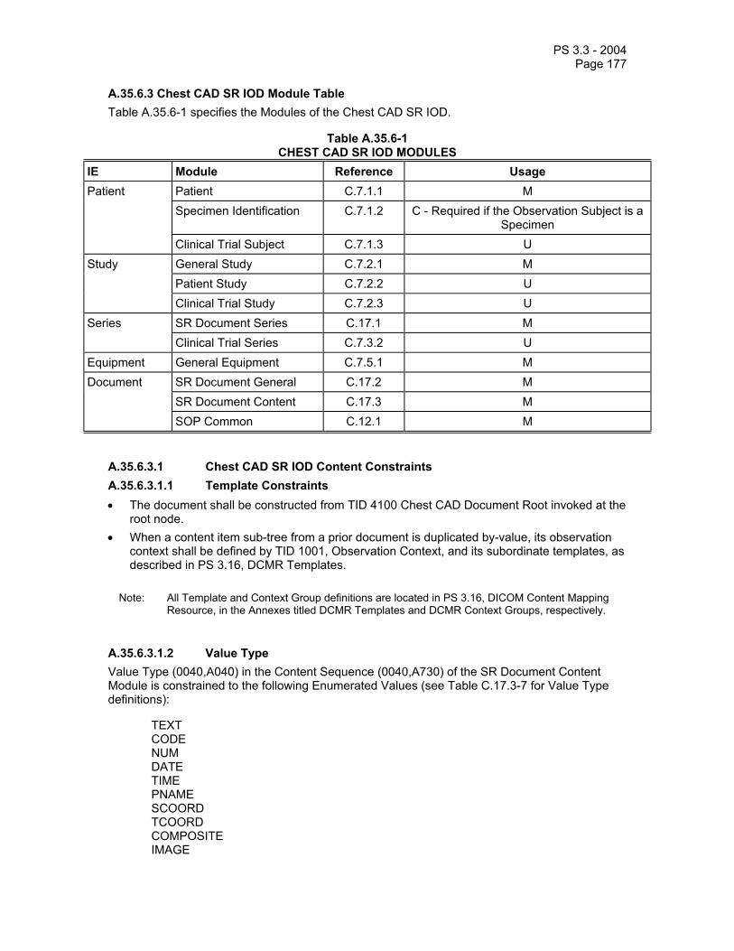
PS 3.3 - 2004 Page 177
A.35.6.3 Chest CAD SR IOD Module Table Table A.35.6-1 specifies the Modules of the Chest CAD SR IOD.
Table A.35.6-1 CHEST CAD SR IOD MODULES
IE Module Reference Usage Patient Patient C.7.1.1 M Specimen Identification C.7.1.2 C - Required if the Observation Subject is a
Specimen Clinical Trial Subject C.7.1.3 U Study General Study C.7.2.1 M Patient Study C.7.2.2 U Clinical Trial Study C.7.2.3 U Series SR Document Series C.17.1 M Clinical Trial Series C.7.3.2 U Equipment General Equipment C.7.5.1 M Document SR Document General C.17.2 M SR Document Content C.17.3 M SOP Common C.12.1 M
A.35.6.3.1 Chest CAD SR IOD Content Constraints A.35.6.3.1.1 Template Constraints • The document shall be constructed from TID 4100 Chest CAD Document Root invoked at the
root node. • When a content item sub-tree from a prior document is duplicated by-value, its observation
context shall be defined by TID 1001, Observation Context, and its subordinate templates, as described in PS 3.16, DCMR Templates.
Note: All Template and Context Group definitions are located in PS 3.16, DICOM Content Mapping
Resource, in the Annexes titled DCMR Templates and DCMR Context Groups, respectively.
A.35.6.3.1.2 Value Type Value Type (0040,A040) in the Content Sequence (0040,A730) of the SR Document Content Module is constrained to the following Enumerated Values (see Table C.17.3-7 for Value Type definitions):
TEXT CODE NUM DATE TIME PNAME SCOORD TCOORD COMPOSITE IMAGE

PS 3.3 - 2004 Page 178
CONTAINER UIDREF WAVEFORM
A.35.6.3.1.3 Relationship Constraints The Chest CAD SR IOD makes use of by-reference INFERRED FROM, by-reference SELECTED FROM, and by-reference HAS PROPERTIES relationships. Other relationships by-reference are forbidden. Table A.35.6-2 specifies the relationship constraints of this IOD. See Table C.17.3-8 for Relationship Type definitions.
Table A.35.6-2 RELATIONSHIP CONTENT CONSTRAINTS FOR CHEST CAD SR IOD
Source Value Type Relationship Type (Enumerated Values)
Target Value Type
CONTAINER CONTAINS CODE, NUM, IMAGE1, CONTAINER.
TEXT, CODE, NUM, CONTAINER
HAS OBS CONTEXT TEXT, CODE, NUM, DATE, TIME, PNAME, UIDREF, COMPOSITE1.
IMAGE, WAVEFORM HAS ACQ CONTEXT TEXT, CODE, DATE, TIME, NUM.
CONTAINER, CODE, COMPOSITE
HAS CONCEPT MOD TEXT, CODE2.
TEXT, CODE, NUM HAS PROPERTIES TEXT, CODE, NUM, DATE, IMAGE1, WAVEFORM1, SCOORD, TCOORD.
CODE, NUM INFERRED FROM CODE, NUM, IMAGE1, WAVEFORM1, SCOORD, TCOORD, CONTAINER.
SCOORD SELECTED FROM IMAGE1.
TCOORD SELECTED FROM SCOORD, IMAGE1, WAVEFORM1.
Note: 1. Which SOP Classes the IMAGE or COMPOSITE Value Type may refer to, is documented in the Conformance Statement for an application (see PS 3.2 and PS 3.4). 2. The HAS CONCEPT MOD relationship is used to modify the meaning of the Concept Name of a Source Content Item, for example to provide a more descriptive explanation, a different language translation, or to define a post-coordinated concept.
A.35.7 Procedure Log Information Object Definition A.35.7.1 Procedure Log Information Object Description The Procedure Log IOD is intended for the representation of reports or logs of time-stamped events occurring during an extended diagnostic or interventional procedure, typical of the cardiac catheterization lab.
A.35.7.2 Procedure Log IOD Entity-Relationship Model The E-R Model in Section A.1.2 of this Part applies to the Procedure Log IOD. Table A.35.7-1 specifies the Modules of the Procedure Log IOD.
Note: Unlike some other SR IODs, the Frame of Reference IE is critical to the synchronized time stamping of events in the Procedure Log IOD and to multi-modality coordination.

PS 3.3 - 2004 Page 179
A.35.7.3 Procedure Log IOD Module Table Table A.35.7-1
PROCEDURE LOG IOD MODULES IE Module Reference Usage Patient Patient C.7.1.1 M Clinical Trial Subject C.7.1.3 U Study General Study C.7.2.1 M Clinical Trial Study C.7.2.3 U Series SR Document Series C.17.1 M Clinical Trial Series C.7.3.2 U Frame of Reference
Synchronization C.7.4.2 M
Equipment General Equipment C.7.5.1 M Document SR Document General C.17.2 M SR Document Content C.17.3 M SOP Common C.12.1 M
A.35.7.3.1 Procedure Log IOD Content Constraints A.35.7.3.1.1 Template The document may be constructed from Baseline TID 3001 "Procedure Log" (defined in PS3.16) invoked at the root node.
Note: This template defines a container (the root) with subsidiary content items, each of which represents a single procedure log entry. There is a defined recording observer (the person responsible for recording the log, generally a technician or nurse). The log entries follow a canonical model of a coded log entry type (the concept name of the content item), the value associated with the concept name as one of the SR Value Types, and optionally a subsidiary free text comment and/or an identifier of the author or device source of the log entry (which may be other than the recording observer).
A.35.7.3.1.2 Observation DateTime Each Item in the Content Sequence (0040,A730) of the SR Document Content Module that is a target of a "CONTAINS" relationship from the root node, i.e., the first level Log Content Items, shall include the Observation DateTime (0040,A032) as a Type 1 attribute. This attribute shall represent the datetime at which the event recorded in the Content Item occurred, not the time at which the Item was recorded.
The first level Procedure Log Content Items in the Content Sequence shall be strictly ordered by monotonically increasing Observation DateTime values.
The Observation DateTime shall be specified to a precision of one second or finer.
A.35.7.3.1.3 Value Type Value Type (0040,A040) in the Content Sequence (0040,A730) of the SR Document Content Module is constrained to the following Enumerated Values (see Table C.17-7 for Value Type definitions):

PS 3.3 - 2004 Page 180
CODE CONTAINER COMPOSITE DATETIME DATE IMAGE NUM PNAME TEXT TIME UIDREF WAVEFORM
A.35.7.3.1.4 Relationship Constraints Relationships between Content Items in the content of this IOD shall be conveyed in the by-value mode. See Table C.17-8 for Relationship Type definitions.
Notes: 1. Relationships by-reference are forbidden. Therefore, Referenced Content Item Identifier (0040,DB73) is not present in any of the Content Items within the SR Document Content Module. 2. CONTAINERs are not permitted as a target of any relationship.
Table A.35.7-2 specifies the relationship constraints of this IOD.
Table A.35.7-2 RELATIONSHIP CONTENT CONSTRAINTS FOR PROCEDURE LOG IOD
Source Value Type Relationship Type (Enumerated Values)
Target Value Type
CONTAINER CONTAINS TEXT, CODE, NUM, PNAME, COMPOSITE, IMAGE, WAVEFORM
any type HAS OBS CONTEXT TEXT, CODE, NUM, DATETIME, UIDREF, PNAME
CONTAINER, IMAGE, WAVEFORM, COMPOSITE
HAS ACQ CONTEXT TEXT, CODE, NUM, DATETIME, DATE, TIME, UIDREF, PNAME
any type HAS CONCEPT MOD TEXT, CODE
any type (except CONTAINER)
HAS PROPERTIES TEXT, CODE, NUM, DATETIME, UIDREF, PNAME
TEXT, CODE, NUM INFERRED FROM IMAGE, WAVEFORM, COMPOSITE
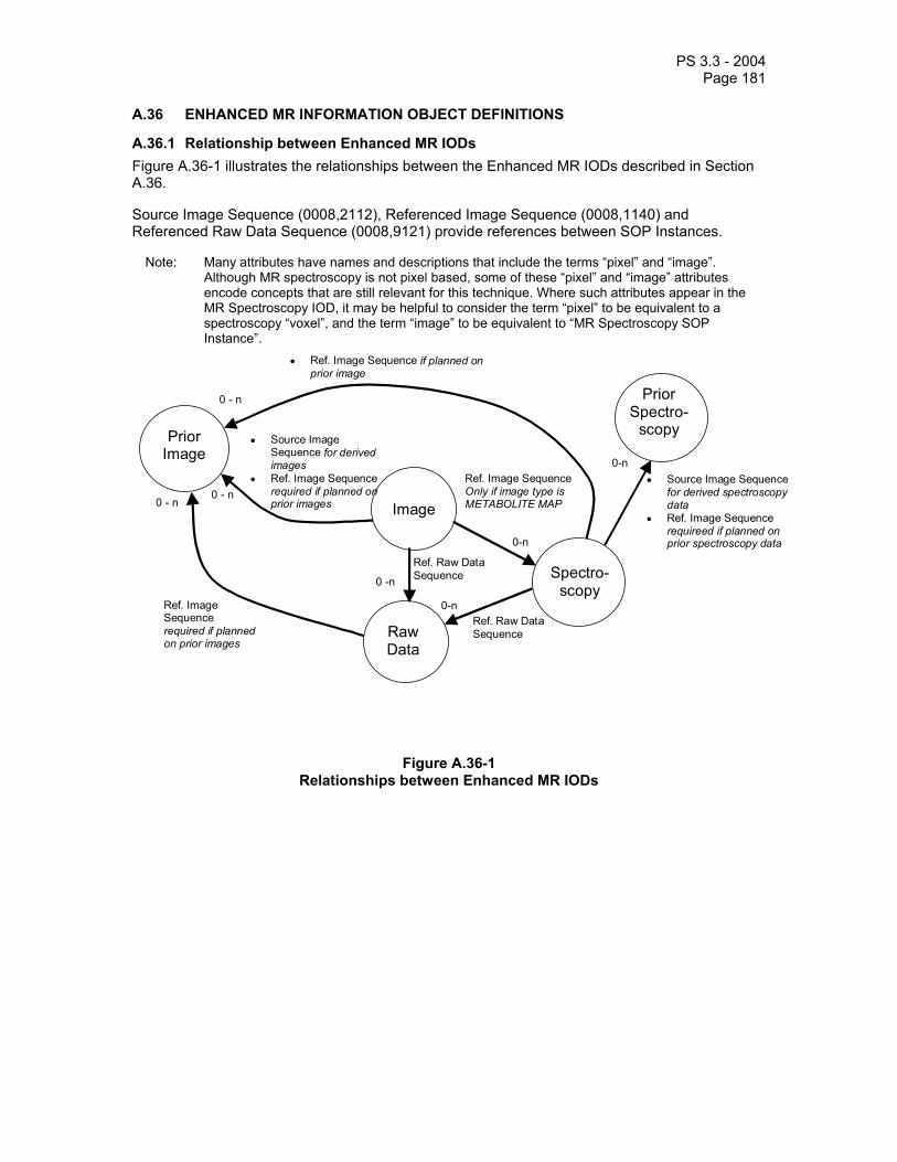
PS 3.3 - 2004 Page 181
A.36 ENHANCED MR INFORMATION OBJECT DEFINITIONS
A.36.1 Relationship between Enhanced MR IODs Figure A.36-1 illustrates the relationships between the Enhanced MR IODs described in Section A.36.
Source Image Sequence (0008,2112), Referenced Image Sequence (0008,1140) and Referenced Raw Data Sequence (0008,9121) provide references between SOP Instances.
Note: Many attributes have names and descriptions that include the terms “pixel” and “image”. Although MR spectroscopy is not pixel based, some of these “pixel” and “image” attributes encode concepts that are still relevant for this technique. Where such attributes appear in the MR Spectroscopy IOD, it may be helpful to consider the term “pixel” to be equivalent to a spectroscopy “voxel”, and the term “image” to be equivalent to “MR Spectroscopy SOP Instance”.
Image
Spectro- scopy
Raw Data
0 -n
0-n
Prior Image
• Source Image Sequence for derived images
• Ref. Image Sequence required if planned on prior images
0 - n 0 - n
Ref. Image Sequence required if planned on prior images
Ref. Raw DataSequence
Ref. Image SequenceOnly if image type is METABOLITE MAP
0-n
Ref. Raw DataSequence
• Source Image Sequence for derived spectroscopy data
• Ref. Image Sequence requireed if planned on prior spectroscopy data
0 - n Prior Spectro-
scopy
• Ref. Image Sequence if planned on prior image
0-n
Figure A.36-1 Relationships between Enhanced MR IODs

PS 3.3 - 2004 Page 182
A.36.2 Enhanced MR Image Information Object Definition A.36.2.1 Enhanced MR Image IOD Description The Enhanced Magnetic Resonance (MR) Image Information Object Definition (IOD) specifies an image, which has been created by a magnetic resonance device.
A.36.2.2 Enhanced MR Image Entity-Relationship Model The E-R Model in section A.1.2 depicts those components of the DICOM Information Model, which directly reference the Enhanced MR Image IOD.
A.36.2.3 Enhanced MR Image IOD Module Table Table A.36-1
ENHANCED MR IMAGE IOD MODULES IE Module Reference Usage
Patient C.7.1.1 M Patient Specimen Identification C.7.1.2 U
Clinical Trial Subject C.7.1.3 U General Study C.7.2.1 M Study Patient Study C.7.2.2 U
Clinical Trial Study C.7.2.3 U Series General Series C.7.3.1 M Clinical Trial Series C.7.3.2 U MR Series C.8.13.6 M
Frame of Reference C.7.4.1 M Frame of Reference Synchronization C.7.4.2 C- Required if time synchronization
was applied. Equipment General Equipment C.7.5.1 M
Image Pixel C.7.6.3 M Enhanced Contrast/Bolus
C.7.6.4b C - Required if contrast media were applied.
Multi-frame Functional Groups
C.7.6.16 M
Multi-frame Dimension C.7.6.17 M Cardiac Synchronization
C.7.6.18.1 C - Required if cardiac synchronization was applied.
Respiratory Synchronization
C.7.6.18.2 C - Required if respiratory synchronization was applied.
Bulk Motion Synchronization
C.7.6.18.3 C - Required if bulk motion synchronization was applied.
Supplemental Palette Color Lookup Table
C.7.6.19 C – Required if Pixel Presentation (0008,9205) in the Enhanced MR Image Module equals COLOR or
MIXED. Acquisition Context C.7.6.14 M
Image
Enhanced MR Image C.8.13.1 M

PS 3.3 - 2004 Page 183
MR Pulse Sequence C.8.13.4 C – Required if Image Type (0008,0008) Value 1 is ORIGINAL
or MIXED. May be present otherwise.
Softcopy Presentation LUT
C.11.6 M
SOP Common C.12.1 M A.36.2.3.1 Enhanced MR Image IOD Content Constraints The General Image Module, Overlay Plane Module, Curve Module and VOI LUT Module shall not be used in a Standard Extended SOP Class of the Enhanced MR Image.
Note: In order to annotate images, whether during acquisition or subsequently, SOP Instances of the Grayscale Softcopy Presentation State Storage or the Structured Report Storage SOP Classes that reference the image SOP Instance, may be used.
No standard mechanism is provided for inclusion of annotations within the image SOP Instance itself, and implementers are discouraged from using private extensions to circumvent this restriction.
Grayscale Softcopy Presentation State Storage Instances that are generated during acquisition may be referenced from the Image SOP Instance by using the Referenced Grayscale Presentation State Sequence in the MR Image and Spectroscopy Instance Macro invoked from the Enhanced MR Image Module. See C.8.13.2.
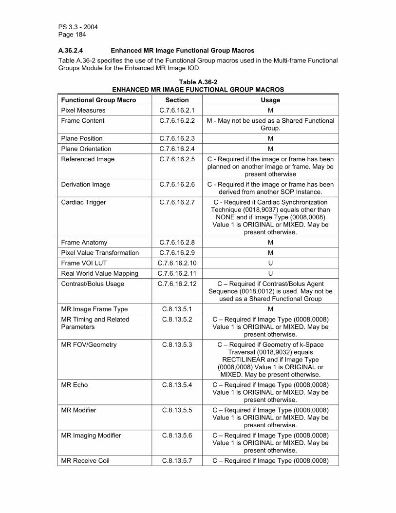
PS 3.3 - 2004 Page 184
A.36.2.4 Enhanced MR Image Functional Group Macros Table A.36-2 specifies the use of the Functional Group macros used in the Multi-frame Functional Groups Module for the Enhanced MR Image IOD.
Table A.36-2 ENHANCED MR IMAGE FUNCTIONAL GROUP MACROS
Functional Group Macro Section Usage Pixel Measures C.7.6.16.2.1 M Frame Content C.7.6.16.2.2 M - May not be used as a Shared Functional
Group. Plane Position C.7.6.16.2.3 M Plane Orientation C.7.6.16.2.4 M Referenced Image C.7.6.16.2.5 C - Required if the image or frame has been
planned on another image or frame. May be present otherwise
Derivation Image C.7.6.16.2.6 C - Required if the image or frame has been derived from another SOP Instance.
Cardiac Trigger C.7.6.16.2.7 C - Required if Cardiac Synchronization Technique (0018,9037) equals other than
NONE and if Image Type (0008,0008) Value 1 is ORIGINAL or MIXED. May be
present otherwise. Frame Anatomy C.7.6.16.2.8 M Pixel Value Transformation C.7.6.16.2.9 M Frame VOI LUT C.7.6.16.2.10 U Real World Value Mapping C.7.6.16.2.11 U Contrast/Bolus Usage C.7.6.16.2.12 C – Required if Contrast/Bolus Agent
Sequence (0018,0012) is used. May not be used as a Shared Functional Group
MR Image Frame Type C.8.13.5.1 M MR Timing and Related Parameters
C.8.13.5.2 C – Required if Image Type (0008,0008) Value 1 is ORIGINAL or MIXED. May be
present otherwise. MR FOV/Geometry C.8.13.5.3 C – Required if Geometry of k-Space
Traversal (0018,9032) equals RECTILINEAR and if Image Type
(0008,0008) Value 1 is ORIGINAL or MIXED. May be present otherwise.
MR Echo C.8.13.5.4 C – Required if Image Type (0008,0008) Value 1 is ORIGINAL or MIXED. May be
present otherwise. MR Modifier C.8.13.5.5 C – Required if Image Type (0008,0008)
Value 1 is ORIGINAL or MIXED. May be present otherwise.
MR Imaging Modifier C.8.13.5.6 C – Required if Image Type (0008,0008) Value 1 is ORIGINAL or MIXED. May be
present otherwise. MR Receive Coil C.8.13.5.7 C – Required if Image Type (0008,0008)

PS 3.3 - 2004 Page 185
Value 1 is ORIGINAL or MIXED. May be present otherwise.
MR Transmit Coil C.8.13.5.8 C – Required if Image Type (0008,0008) Value 1 is ORIGINAL or MIXED. May be
present otherwise. MR Diffusion C.8.13.5.9 C - Required if Acquisition Contrast
(0008,9209) in any MR Image Frame Type Functional Group in the SOP Instance equals DIFFUSION and Image Type (0008,0008) Value 1 is ORIGINAL or MIXED. May be present otherwise.
MR Averages C.8.13.5.10 C – Required if Image Type (0008,0008) Value 1 is ORIGINAL or MIXED. May be
present otherwise. MR Spatial Saturation C.8.13.5.11 C - Required if Spatial Pre-saturation
(0018,9027) equals SLAB for any frame in the SOP Instance and Image Type
(0008,0008) Value 1 is ORIGINAL or MIXED. May be present otherwise.
MR Metabolite Map C.8.13.5.12 C – Required if Image Type (0008,0008) Value 3 equals METABOLITE_MAP. May be
present otherwise. MR Velocity Encoding C.8.13.5.13 C – Required if Phase Contrast (0018,9014)
equals YES and Image Type (0008,0008) Value 1 is ORIGINAL or MIXED. May be
present otherwise.
A.36.3 MR Spectroscopy Information Object Definition A.36.3.1 MR Spectroscopy IOD Description The Magnetic Resonance (MR) Spectroscopy Information Object Definition (IOD) specifies spectroscopic data, which has been created by a magnetic resonance device.
A.36.3.2 MR Spectroscopy entity-relationship model The E-R Model in section A.1.2 depicts those components of the DICOM Information Model, which directly reference the MR Spectroscopy IOD.

PS 3.3 - 2004 Page 186
A.36.3.3 MR Spectroscopy IOD Module Table Table A.36-3
MR SPECTROSCOPY IOD MODULES IE Module Reference Usage
Patient C.7.1.1 M Patient Specimen Identification C.7.1.2 U
Clinical Trial Subject C.7.1.3 U General Study C.7.2.1 M Study Patient Study C.7.2.2 U
Clinical Trial Study C.7.2.3 U
Series General Series C.7.3.1 M Clinical Trial Series C.7.3.2 U MR Series C.8.13.6 M
Frame of Reference C.7.4.1 M Frame of Reference Synchronization C.7.4.2 C- Required if time synchronization
was applied. Equipment General Equipment C.7.5.1 M
Enhanced Contrast/Bolus
C.7.6.4b C – Required if contrast media were applied.
Multi-frame Functional Groups
C.7.6.16 M
Multi-frame Dimension C.7.6.17 M
Cardiac Synchronization
C.7.6.18.1 C - Required if cardiac synchronization was applied.
Respiratory Synchronization
C.7.6.18.2 C - Required if respiratory synchronization was applied.
Bulk Motion Synchronization
C.7.6.18.3 C - Required if bulk motion synchronization was applied.
Acquisition Context C.7.6.14 M
MR Spectroscopy C.8.14.1 M
MR Spectroscopy Pulse Sequence
C.8.14.2 C – Required if Image Type (0008,0008) Value 1 is ORIGINAL.
May be present otherwise. MR Spectroscopy Data C.8.14.3 M
MR Spectroscopy
SOP Common C.12.1 M
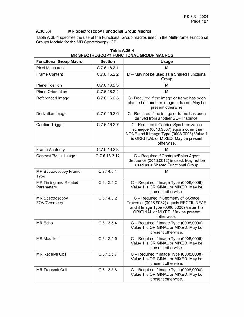
PS 3.3 - 2004 Page 187
A.36.3.4 MR Spectroscopy Functional Group Macros Table A.36-4 specifies the use of the Functional Group macros used in the Multi-frame Functional Groups Module for the MR Spectroscopy IOD.
Table A.36-4 MR SPECTROSCOPY FUNCTIONAL GROUP MACROS
Functional Group Macro Section Usage Pixel Measures C.7.6.16.2.1 M Frame Content C.7.6.16.2.2 M – May not be used as a Shared Functional
Group Plane Position C.7.6.16.2.3 M Plane Orientation C.7.6.16.2.4 M Referenced Image C.7.6.16.2.5 C - Required if the image or frame has been
planned on another image or frame. May be present otherwise
Derivation Image C.7.6.16.2.6 C - Required if the image or frame has been derived from another SOP Instance.
Cardiac Trigger C.7.6.16.2.7 C - Required if Cardiac Synchronization Technique (0018,9037) equals other than
NONE and if Image Type (0008,0008) Value 1 is ORIGINAL or MIXED. May be present
otherwise. Frame Anatomy C.7.6.16.2.8 M Contrast/Bolus Usage C.7.6.16.2.12 C – Required if Contrast/Bolus Agent
Sequence (0018,0012) is used. May not be used as a Shared Functional Group
MR Spectroscopy Frame Type
C.8.14.5.1 M
MR Timing and Related Parameters
C.8.13.5.2 C – Required if Image Type (0008,0008) Value 1 is ORIGINAL or MIXED. May be
present otherwise. MR Spectroscopy FOV/Geometry
C.8.14.3.2 C – Required if Geometry of k-Space Traversal (0018,9032) equals RECTILINEAR
and if Image Type (0008,0008) Value 1 is ORIGINAL or MIXED. May be present
otherwise. MR Echo C.8.13.5.4 C – Required if Image Type (0008,0008)
Value 1 is ORIGINAL or MIXED. May be present otherwise.
MR Modifier C.8.13.5.5 C – Required if Image Type (0008,0008) Value 1 is ORIGINAL or MIXED. May be
present otherwise. MR Receive Coil C.8.13.5.7 C – Required if Image Type (0008,0008)
Value 1 is ORIGINAL or MIXED. May be present otherwise.
MR Transmit Coil C.8.13.5.8 C – Required if Image Type (0008,0008) Value 1 is ORIGINAL or MIXED. May be
present otherwise.

PS 3.3 - 2004 Page 188
MR Diffusion C.8.13.5.9 C - Required if Acquisition Contrast (0008,9209) in any MR Image Frame Type
Functional Group in the SOP Instance equals DIFFUSION and Image Type (0008,0008) Value 1 is ORIGINAL or MIXED. May be
present otherwise. MR Averages C.8.13.5.10 C – Required if Image Type (0008,0008)
Value 1 is ORIGINAL or MIXED. May be present otherwise.
MR Spatial Saturation C.8.13.5.11 C - Required if Spatial Pre-saturation (0018,9027) equals SLAB for any frame in the SOP Instance and Image Type (0008,0008)
Value 1 is ORIGINAL or MIXED. May be present otherwise.
MR Velocity Encoding C.8.13.5.13 C – Required if Phase Contrast (0018,9014) equals YES and Image Type (0008,0008) Value 1 is ORIGINAL or MIXED. May be
present otherwise.
A.37 RAW DATA INFORMATION OBJECT DEFINITION
A.37.1 Raw Data IOD Description The Raw Data Information Object Definition (IOD) specifies raw data.
A.37.2 Raw Data entity-relationship model The E-R Model in section A.1.2 depicts those components of the DICOM Information Model, which directly reference the Raw Data IOD.

PS 3.3 - 2004 Page 189
A.37.3 Raw Data IOD Module Table Table A.37-1
RAW DATA IOD MODULES IE Module Reference Usage
Patient C.7.1.1 M Patient Specimen Identification C.7.1.2 U
Clinical Trial Subject C.7.1.3 U General Study C.7.2.1 M Study Patient Study C.7.2.2 U
Clinical Trial Study C.7.2.3 U Series General Series C.7.3.1 M Clinical Trial Series C.7.3.2 U
Frame of Reference C.7.4.1 U Frame of Reference Synchronization C.7.4.2 C- Required if time synchronization
was applied. Equipment General Equipment C.7.5.1 M
Acquisition Context C.7.6.14 M Raw Data C.19.1 M
Raw Data
SOP Common C.12.1 M
A.38 ENHANCED COMPUTED TOMOGRAPHY IMAGE INFORMATION OBJECT DEFINITION
A.38.1 Enhanced CT Image Information Object Definition A.38.1.1 Enhanced CT Image IOD Description The Enhanced Computed Tomography (CT) Image Information Object Definition (IOD) specifies an image that has been created by a computed tomography imaging device.
A.38.1.2 Enhanced CT Image IOD Entity-Relationship Model The E-R Model in Section A.1.2 depicts those components of the DICOM Information Model that directly reference the Enhanced CT Image IOD.
A.38.1.3 Enhanced CT Image IOD Module Table Table A.38-1
ENHANCED CT IMAGE IOD MODULES IE Module Reference Usage
Patient C.7.1.1 M Specimen Identification
C.7.1.2 U Patient
Clinical Trial Subject C.7.1.3 U General Study C.7.2.1 M Patient Study C.7.2.2 U
Study
Clinical Trial Study C.7.2.3 U Series General Series C.7.3.1 M

PS 3.3 - 2004 Page 190
CT Series C.8.15.1 M
Clinical Trial Series C.7.3.2 U Frame of Reference C.7.4.1 M Frame of
Reference Synchronization C.7.4.2 C- Required if time synchronization was applied.
Equipment General Equipment C.7.5.1 M Image Pixel C.7.6.3 M Enhanced Contrast/Bolus
C.7.6.4b C – Required if contrast media was applied.
Multi-frame Functional Groups
C.7.6.16 M
Multi-frame Dimension C.7.6.17 M Cardiac Synchronization
C.7.6.18.1 C – Required if cardiac synchronization was applied.
Respiratory Synchronization
C.7.6.18.2 C – Required if respiratory synchronization was applied.
Supplemental Palette Color Lookup Table
C.7.6.19 C – Required if Pixel Presentation (0008,9205) in the Enhanced CT Image Module equals COLOR or
MIXED. Acquisition Context C.7.6.14 M Enhanced CT Image C.8.15.2 M Softcopy Presentation LUT
C.11.6 M
Image
SOP Common C.12.1 M
A.38.1.3.1 Enhanced CT Image IOD Content Constraints The General Image Module, Overlay Plane Module, Curve Module and VOI LUT Module shall not be used in a Standard Extended SOP Class of the Enhanced CT Image.
Note: In order to annotate images, whether during acquisition or subsequently, SOP Instances of the Grayscale Softcopy Presentation State Storage or the Structured Report Storage SOP Classes that reference the image SOP Instance, may be used.
No standard mechanism is provided for inclusion of annotations within the image SOP Instance itself, and implementers are discouraged from using private extensions to circumvent this restriction.
Grayscale Softcopy Presentation State Storage Instances that are generated during acquisition may be referenced from the Image SOP Instance by using the Referenced Grayscale Presentation State Sequence in the Enhanced CT Image Module. See C.8.15.2.
A.38.1.4 Enhanced CT Image Functional Group Macros Table A.38-2 specifies the use of the Functional Group macros used in the Multi-frame Functional Group Module for the Enhanced CT Image IOD.
Table A.38-2 ENHANCED CT IMAGE FUNCTIONAL GROUP MACROS

PS 3.3 - 2004 Page 191
Function Group Macro Section Usage Pixel Measures C.7.6.16.2.1 M Frame Content C.7.6.16.2.2 M – May not be used as a Shared
Functional Group. Plane Position C.7.6.16.2.3 M Plane Orientation C.7.6.16.2.4 M Referenced Image C.7.6.16.2.5 C – Required if the image or frame has
been planned on another image or frame, may be present otherwise.
Derivation Image C.7.6.16.2.6 C – Required if the image or frame has been derived from another SOP
Instance. Cardiac Trigger C.7.6.16.2.7 C – Required if Cardiac
Synchronization Technique (0018,9037) equals other than NONE
and if Image Type (0008,0008) Value 1 is ORIGINAL or MIXED. May be
present otherwise. Frame Anatomy C.7.6.16.2.8 M Frame VOI LUT C.7.6.16.2.10 U Real World Value Mapping C.7.6.16.2.11 U Contrast/Bolus Usage C.7.6.16.2.12 C – Required if Contrast/Bolus Agent
Sequence (0018,0012) is used. May not be used as a Shared Functional
Group CT Image Frame Type C.8.15.3.1 M CT Acquisition Type C.8.15.3.2 C – Required if Image Type
(0008,0008) Value 1 is ORIGINAL or MIXED, may be present otherwise.
CT Acquisition Details C.8.15.3.3 C – Required if Image Type (0008,0008) Value 1 is ORIGINAL or MIXED, may be present otherwise.
CT Table Dynamics C.8.15.3.4 C – Required if Image Type (0008,0008) Value 1 is ORIGINAL or MIXED, may be present otherwise.
CT Position C.8.15.3.5 C – Required if Image Type (0008,0008) Value 1 is ORIGINAL or
MIXED, may be present otherwise CT Geometry C.8.15.3.6 C – Required if Image Type
(0008,0008) Value 1 is ORIGINAL or MIXED, may be present otherwise.
CT Reconstruction C.8.15.3.7 C – Required if Image Type (0008,0008) Value 1 is ORIGINAL or
MIXED and Acquisition Type (0018,9302) is other than
CONSTANT_ANGLE, may be present otherwise.
CT Exposure C.8.15.3.8 C – Required if Image Type

PS 3.3 - 2004 Page 192
(0008,0008) Value 1 is ORIGINAL or MIXED, may be present otherwise.
CT X-ray Details C.8.15.3.9 C – Required if Image Type (0008,0008) Value 1 is ORIGINAL or MIXED, may be present otherwise.
CT Pixel Value Transformation C.8.15.3.10 M
A.39 SPATIAL REGISTRATION INFORMATION OBJECT DEFINITION
A.39.1 Spatial Registration IOD Description
The Registration IOD specifies the spatial relationship between Frames of Reference..
A.39.2 Spatial Registration IOD Entity-Relationship Model
Patient
Study
is the subject
of
contains
Spatially and temporally
defines creates
Equipment Frame of Reference
Spatial Registration
contains
Series
0,n
0-1 1 11,n
1-n1,n
1
1,n
1
Figure A.39-1 SPATIAL REGISTRATION INFORMATION OBJECT DEFINITION E-R MODEL
A.39.3 Spatial Registration IOD Module Table Table A.39-1 SPATIAL REGISTRATION IOD MODULES

PS 3.3 - 2004 Page 193
IE Module Reference Usage Patient C.7.1.1 M Specimen Identification C.7.1.2 U
Patient
Clinical Trial Subject C.7.1.3 U General Study C.7.2.1 M Patient Study C.7.2.2 U
Study
Clinical Trial Study C.7.2.3 U General Series C.7.3.1 M Clinical Trial Series C.7.3.2 U
Series
Spatial Registration Series C.20.1 M Frame of Reference Frame of Reference C.7.4.1 M Equipment General Equipment C.7.5.1 M Spatial Registration Spatial Registration C.20.2 M Common Instance Reference C.12.2 M SOP Common C.12.1 M
A.40 SPATIAL FIDUCIALS INFORMATION OBJECT DEFINITION
A.40.1 Spatial Fiducials IOD Description
The Fiducials IOD specifies the spatial relationship between the Composite Fiducial instance, to one or more images.
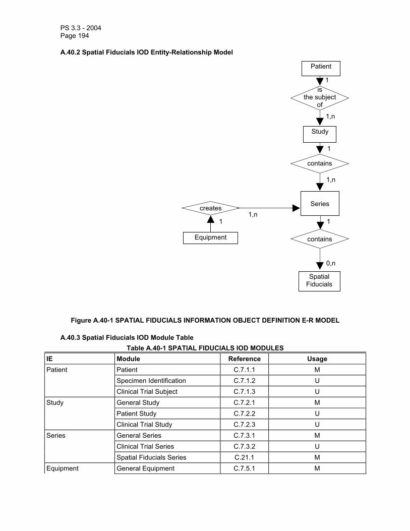
PS 3.3 - 2004 Page 194
A.40.2 Spatial Fiducials IOD Entity-Relationship Model
Patient
Study
is the subject
of
contains
creates
Equipment
Spatial Fiducials
contains
Series
0,n
1 11,n
1,n
1
1,n
1
Figure A.40-1 SPATIAL FIDUCIALS INFORMATION OBJECT DEFINITION E-R MODEL
A.40.3 Spatial Fiducials IOD Module Table Table A.40-1 SPATIAL FIDUCIALS IOD MODULES
IE Module Reference Usage Patient C.7.1.1 M Specimen Identification C.7.1.2 U
Patient
Clinical Trial Subject C.7.1.3 U General Study C.7.2.1 M Patient Study C.7.2.2 U
Study
Clinical Trial Study C.7.2.3 U General Series C.7.3.1 M Series Clinical Trial Series C.7.3.2 U
Spatial Fiducials Series C.21.1 M Equipment General Equipment C.7.5.1 M

PS 3.3 - 2004 Page 195
Spatial Fiducials Spatial Fiducials C.21.2 M Common Instance Reference C.12.2 M SOP Common C.12.1 M
A.41 OPHTHALMIC PHOTOGRAPHY 8 BIT IMAGE INFORMATION OBJECT DEFINITION
This Section defines an Information Object to be used with several types of ophthalmic photographic imaging devices including fundus cameras, slit lamp cameras, scanning laser devices, stereoscopic cameras, video equipment and digital photographic equipment, with 8 bit resolution per pixel in each image plane.
A.41.1 Ophthalmic Photography 8 Bit Image IOD Description The Ophthalmic Photography 8 Bit Image IOD specifies a single-frame or a multi-frame image acquired on a digital photographic DICOM modality. This IOD can be used to encode single ophthalmic images and cine sequences.
A.41.2 Ophthalmic Photography 8 Bit Image IOD Entity-Relationship Model The E-R Model in Section A.1.2 of this Part depicts those components of the DICOM Information Model that directly reference the Ophthalmic Photography 8-Bit Image IOD, with exception of the Curve, VOI LUT, and Modality LUT entities, which are not used. Table A.41-1 specifies the Modules of the Ophthalmic Photography 8 Bit Image IOD.
A.41.3 Ophthalmic Photography 8 Bit Image IOD Modules Table A.41-1
OPHTHALMIC PHOTOGRAPHY 8 BIT IMAGE IOD MODULES IE Module Reference Usage
Patient Patient C.7.1.1 M Specimen
Identification C.7.1.2 C - Required if the Imaging Subject is a Specimen
Clinical Trial Subject C.7.1.3 U Study General Study C.7.2.1 M Patient Study C.7.2.2 U Clinical Trial Study C.7.2.3 U Series General Series C.7.3.1 M Ophthalmic
Photography Series C.8.17.1 M
Clinical Trial Series C.7.3.2 U Frame of Reference
Synchronization C.7.4.2 M
Equipment General Equipment C.7.5.1 M Image General Image C.7.6.1 M Image Pixel C.7.6.3 M Enhanced
Contrast/Bolus C 7.6.4.b C – Required if contrast was administered, see
A.41.4.2 Cine C.7.6.5 C - Required if there is a sequential temporal
relationship between all frames

PS 3.3 - 2004 Page 196
Multi-frame C.7.6.6 M Ophthalmic
Photography Image C.8.17.2 M
Ocular Region Imaged
C.8.17.5 M
Ophthalmic Photography Acquisition Parameters
C.8.17.4 M
Ophthalmic Photographic Parameters
C.8.17.3 M
SOP Common C.12.1 M
A.41.4 Ophthalmic Photography 8 Bit Image IOD Content Constraints The following constraints on Series and Image attributes take precedence over the descriptions given in the Module Attribute Tables.
A.41.4.1 Bits Allocated, Bits Stored, and High Bit For Ophthalmic Photography 8 bit images, the Enumerated Value of Bits Allocated (0028,0100) (Image Pixel Module, C.7.6.3) shall be 8; the Enumerated Value of Bits Stored (0028,0101) shall be 8; and the Enumerated Value of High Bit (0028,0102) shall be 7.
A.41.4.2 Contrast/Bolus Agent Sequence For Contrast/Bolus Agent Sequence (0018,0012), the defined CID 4200 shall be used.
A.42 OPHTHALMIC PHOTOGRAPHY 16 BIT IMAGE INFORMATION OBJECT DEFINITION
This Section defines an Information Object to be used with several types of ophthalmic photographic imaging devices including fundus cameras, slit lamp cameras, scanning laser devices, stereoscopic cameras, video equipment and digital photographic equipment, with16 bit resolution per pixel in each image plane.
A.42.1 Ophthalmic Photography 16 Bit Image IOD Description The Ophthalmic Photography 16 Bit Image IOD specifies a single-frame or a multi-frame image acquired on a digital photographic DICOM modality. This IOD can be used to encode single ophthalmic images and other combinations including cine sequences.
A.42.2 Ophthalmic Photography 16 Bit Image IOD Entity-Relationship Model The E-R Model in Section A.1.2 of this Part depicts those components of the DICOM Information Model that directly reference the Ophthalmic Photography 16-Bit Image IOD, with exception of the Curve, VOI LUT, Frame of Reference and Modality LUT entities, which are not used. Table A.42-1 specifies the Modules of the Ophthalmic Photography 16 Bit Image IOD.
A.42.3 Ophthalmic Photography 16 Bit Image IOD Modules Table A.42-1
OPHTHALMIC PHOTOGRAPHY 16 BIT IMAGE IOD MODULES IE Module Reference Usage
Patient Patient C.7.1.1 M Specimen C.7.1.2 C - Required if the Imaging Subject is a Specimen

PS 3.3 - 2004 Page 197
Identification Clinical Trial Subject C.7.1.3 U Study General Study C.7.2.1 M Patient Study C.7.2.2 U Clinical Trial Study C.7.2.3 U Series General Series C.7.3.1 M Ophthalmic
Photography Series C.8.17.1 M
Clinical Trial Series C.7.3.2 U Frame of Reference
Synchronization C.7.4.2 M
Equipment General Equipment C.7.5.1 M Image General Image C.7.6.1 M Image Pixel C.7.6.3 M Enhanced
Contrast/Bolus C 7.6.4.b C – Required if contrast was administered; see
A.42.4.2 Cine C.7.6.5 C - Required if there is a sequential temporal
relationship between all frames Multi-frame C.7.6.6 M Ophthalmic
Photography Image C.8.17.2 M
Ocular Region Imaged
C.8.17.5 M
Ophthalmic Photography Acquisition Parameters
C.8.17.4 M
Ophthalmic Photographic Parameters
C.8.17.3 M
SOP Common C.12.1 M
A.42.4 Ophthalmic Photography 16 Bit Image IOD Content Constraints The following constraints on Series and Image attributes take precedence over the descriptions given in the Module Attribute Tables.
A.42.4.1 Bits Allocated, Bits Stored, and High Bit For Ophthalmic Photography 16 bit images, the Enumerated Value of Bits Allocated (0028,0100) (Image Pixel Module, C.7.6.3) shall be 16; the Enumerated Value of Bits Stored (0028,0101) shall be 16; and the Enumerated Value of High Bit (0028,0102) shall be 15.
A.42.4.2 Contrast/Bolus Agent Sequence For Contrast/Bolus Agent Sequence (0018,0012), the defined CID 4200 shall be used.

PS 3.3 - 2004 Page 198
A.43 STEREOMETRIC RELATIONSHIP INFORMATION OBJECT DEFINITION
This Section defines an Information Object to be used for linking together images belonging to stereoscopic pairs. A Series IE will typically contain a single Stereometric Relationship IE that references one or more sets of stereoscopic images. Stereoscopic pairs for ophthalmic photographic imaging may include single images, multi-frame images, or cine images.
A.43.1 Stereometric Relationship IOD Entity-Relationship Model
Patient
Study
is the subject
of
contains
creates
Equipment
StereometricRelationship
contains
Series
0,n
1 11,n
1,n
1
1,n
1
Figure A.43-1 STEREOMETRIC RELATIONSHIP INFORMATION OBJECT DEFINITION E-R MODEL
A.43.2 Stereometric Relationship IOD Modules Table A.43-2
STEREOMETRIC RELATIONSHIP IOD MODULES IE Module Reference Usage
Patient Patient C.7.1.1 M Specimen C.7.1.2 C - Required if the Imaging Subject is a Specimen

PS 3.3 - 2004 Page 199
Identification Clinical Trial
Subject C.7.1.3 U
Study General Study C.7.2.1 M Patient Study C.7.2.2 U Clinical Trial Study C.7.2.3 U
Clinical Trial Series C.7.3.2 U Series Stereometric Series
C.8.18.1 M
Equipment General Equipment C.7.5.1 M Stereometric Relationship
Stereometric Relationship Module
C.8.18.2 M
Common Instance Reference Module
C.12.2 M
SOP Common C.12.1 M

PS 3.3 - 2004 Page 200
Annex B Normalized Information Object Definitions (Normative)
B.1 PATIENT INFORMATION OBJECT DEFINITION
B.1.1 IOD description The Patient Information Object Definition is an abstraction of the information describing a patient upon whom medical imaging services are performed. The Patient IOD is tailored by Service Class Definitions that use services which facilitate the exchange of patient-related information between DICOM Application Entities.
A Patient SOP Instance uses the Patient IOD as a basis to describe a real world patient. Each Patient SOP Instance references related Visit SOP Instances and Study SOP Instances as described by the Entity-Relationship diagram in Section 7.
B.1.2 Patient IOD modules Table B.1-1 identifies and defines the Modules that comprise this IOD. Modules listed are either mandatory or optional as specified in PS 3.4. Mandatory Modules contain Attributes that are included in all SOP Instances employing this IOD.
Table B.1-1 PATIENT IOD MODULES
Module Reference Module Description SOP Common C.12.1 Contains SOP common information Patient Relationship C.2.1 References to related SOPs Patient Identification C.2.2 Identifies the real world patient Patient Demographic C.2.3 Describe the patient Patient Medical C.2.4 Medical information about patient
B.2 VISIT INFORMATION OBJECT DEFINITION
B.2.1 IOD description The Visit Information Object Definition is an abstraction of the information that describes a patient attendance to a healthcare provider. Because it is defined generically, this IOD may be used in applications ranging from inpatient hospital to outpatient radiological attendances. It includes such information as the admitting date and time, the admitting diagnosis, and the physician who referred the patient. The Visit IOD is tailored by Service Class Definitions that use services which facilitate the exchange of visit-related information between DICOM Application Entities.
A Visit SOP Instance uses the Visit Information Object Definition as a basis to describe a real world patient visit. Each Visit SOP Instance references related Patient SOP Instances and Study SOP Instances as described by the Entity-Relationship diagram in Section 7.
B.2.2 IOD modules Table B.2-1 identifies and defines the Modules that comprise this IOD. Modules listed are either mandatory or optional as specified in PS 3.4. Mandatory Modules contain Attributes that are included in all SOP Instances employing this IOD.
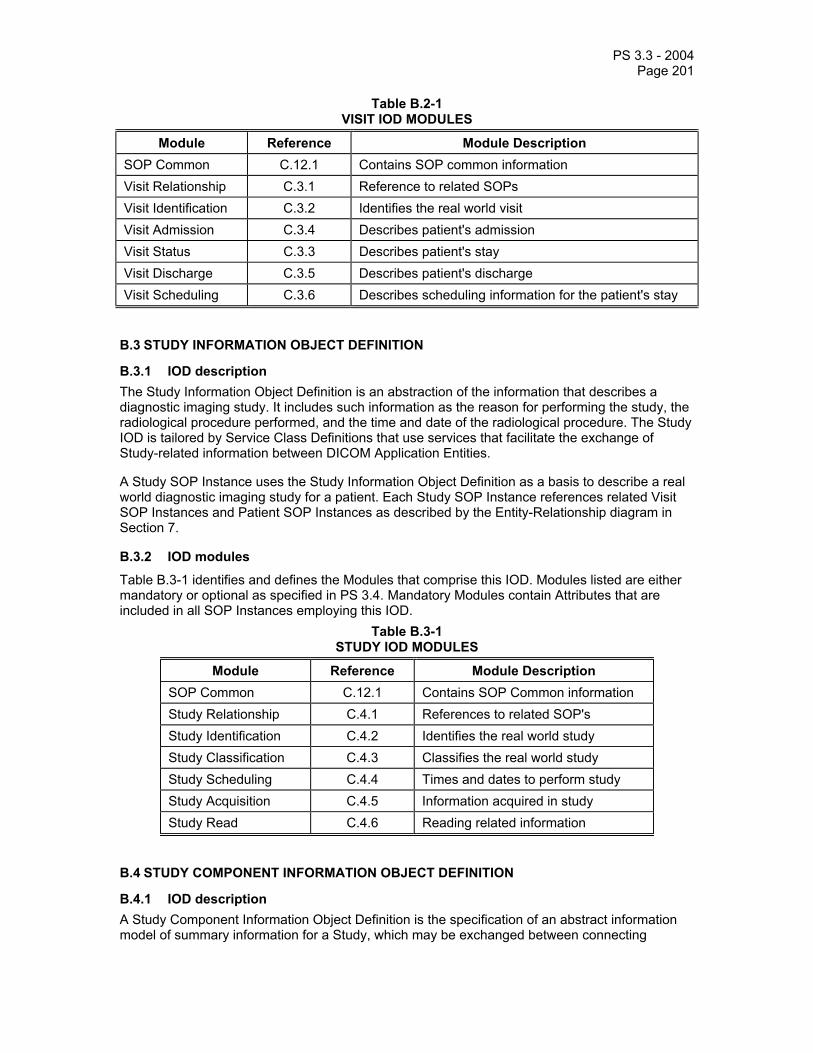
PS 3.3 - 2004 Page 201
Table B.2-1 VISIT IOD MODULES
Module Reference Module Description SOP Common C.12.1 Contains SOP common information Visit Relationship C.3.1 Reference to related SOPs Visit Identification C.3.2 Identifies the real world visit Visit Admission C.3.4 Describes patient's admission Visit Status C.3.3 Describes patient's stay Visit Discharge C.3.5 Describes patient's discharge Visit Scheduling C.3.6 Describes scheduling information for the patient's stay
B.3 STUDY INFORMATION OBJECT DEFINITION
B.3.1 IOD description The Study Information Object Definition is an abstraction of the information that describes a diagnostic imaging study. It includes such information as the reason for performing the study, the radiological procedure performed, and the time and date of the radiological procedure. The Study IOD is tailored by Service Class Definitions that use services that facilitate the exchange of Study-related information between DICOM Application Entities.
A Study SOP Instance uses the Study Information Object Definition as a basis to describe a real world diagnostic imaging study for a patient. Each Study SOP Instance references related Visit SOP Instances and Patient SOP Instances as described by the Entity-Relationship diagram in Section 7.
B.3.2 IOD modules
Table B.3-1 identifies and defines the Modules that comprise this IOD. Modules listed are either mandatory or optional as specified in PS 3.4. Mandatory Modules contain Attributes that are included in all SOP Instances employing this IOD.
Table B.3-1 STUDY IOD MODULES
Module Reference Module Description SOP Common C.12.1 Contains SOP Common information Study Relationship C.4.1 References to related SOP's Study Identification C.4.2 Identifies the real world study Study Classification C.4.3 Classifies the real world study Study Scheduling C.4.4 Times and dates to perform study Study Acquisition C.4.5 Information acquired in study Study Read C.4.6 Reading related information
B.4 STUDY COMPONENT INFORMATION OBJECT DEFINITION
B.4.1 IOD description A Study Component Information Object Definition is the specification of an abstract information model of summary information for a Study, which may be exchanged between connecting
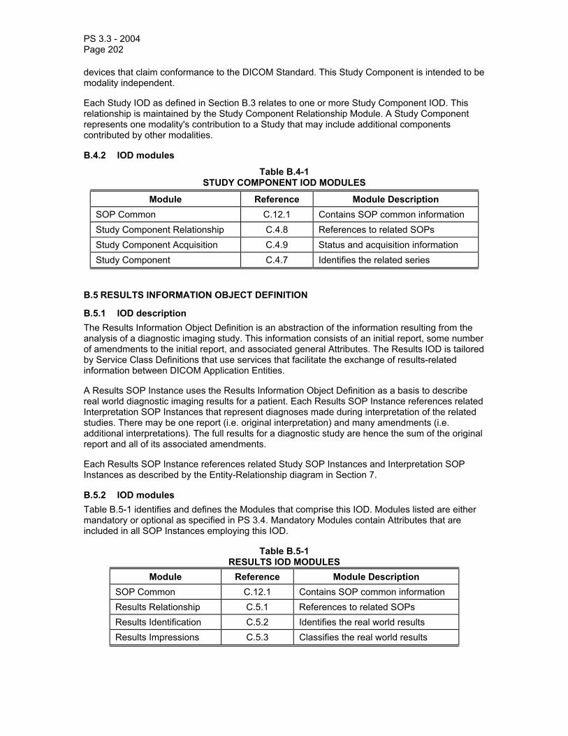
PS 3.3 - 2004 Page 202
devices that claim conformance to the DICOM Standard. This Study Component is intended to be modality independent.
Each Study IOD as defined in Section B.3 relates to one or more Study Component IOD. This relationship is maintained by the Study Component Relationship Module. A Study Component represents one modality's contribution to a Study that may include additional components contributed by other modalities.
B.4.2 IOD modules
Table B.4-1 STUDY COMPONENT IOD MODULES
Module Reference Module Description SOP Common C.12.1 Contains SOP common information Study Component Relationship C.4.8 References to related SOPs Study Component Acquisition C.4.9 Status and acquisition information Study Component C.4.7 Identifies the related series
B.5 RESULTS INFORMATION OBJECT DEFINITION
B.5.1 IOD description The Results Information Object Definition is an abstraction of the information resulting from the analysis of a diagnostic imaging study. This information consists of an initial report, some number of amendments to the initial report, and associated general Attributes. The Results IOD is tailored by Service Class Definitions that use services that facilitate the exchange of results-related information between DICOM Application Entities.
A Results SOP Instance uses the Results Information Object Definition as a basis to describe real world diagnostic imaging results for a patient. Each Results SOP Instance references related Interpretation SOP Instances that represent diagnoses made during interpretation of the related studies. There may be one report (i.e. original interpretation) and many amendments (i.e. additional interpretations). The full results for a diagnostic study are hence the sum of the original report and all of its associated amendments.
Each Results SOP Instance references related Study SOP Instances and Interpretation SOP Instances as described by the Entity-Relationship diagram in Section 7.
B.5.2 IOD modules Table B.5-1 identifies and defines the Modules that comprise this IOD. Modules listed are either mandatory or optional as specified in PS 3.4. Mandatory Modules contain Attributes that are included in all SOP Instances employing this IOD.
Table B.5-1 RESULTS IOD MODULES
Module Reference Module Description SOP Common C.12.1 Contains SOP common information Results Relationship C.5.1 References to related SOPs Results Identification C.5.2 Identifies the real world results Results Impressions C.5.3 Classifies the real world results

PS 3.3 - 2004 Page 203
B.6 INTERPRETATION INFORMATION OBJECT DEFINITION
B.6.1 IOD description The Interpretation Information Object Definition is an abstraction of the information resulting from a single interpretation of a diagnostic imaging study. This interpretation may be either a report (initial interpretation) or an amendment to a report for a diagnostic imaging study. The Interpretation IOD is tailored by Service Class Definitions that use services that facilitate the exchange of interpretation-related information between DICOM Application Entities.
An Interpretation SOP Instance uses the Interpretation Information Object Definition as a basis to describe real world interpretation of a diagnostic imaging study. Each Interpretation SOP Instance references one Results SOP Instance that represent the total diagnosis made for the related study. There may be one report interpretation and many amendment interpretations. The full results for a diagnostic study are hence the sum of the original report and all of its associated amendments.
B.6.2 IOD modules
Table B.6-1 identifies and defines the Modules that comprise this IOD. Modules listed are either mandatory or optional as specified in PS 3.4. Mandatory Modules contain Attributes that are included in all SOP Instances of this IOD.
Table B.6-1 INTERPRETATION IOD MODULES
Module Reference Module Description SOP Common C.12.1 Contains SOP Common information Interpretation Relationship C.6.1 References to related SOPs Interpretation Identification C.6.2 Identifies the real world interpretation Interpretation State C.6.3 State of real world interpretation Interpretation Recording C.6.4 When, by whom the interpretation was
recorded Interpretation Transcription C.6.5 When, by whom the interpretation was
transcribed Interpretation Approval C.6.6 When, by whom the interpretation was
approved
B.7 BASIC FILM SESSION INFORMATION OBJECT DEFINITION
B.7.1 IOD description The Basic Film Session Information Object Definition describes the presentation parameters that are common for all the films of a film session (e.g. number of films, film destination).

PS 3.3 - 2004 Page 204
B.7.2 IOD modules
Table B.7-1 FILM SESSION IOD MODULES
Module Reference Module Description SOP Common C.12.1 Contains SOP Common information Basic Film Session Presentation
C.13.1 Contains Film Session presentations information
Basic Film Session Relationship
C.13.2 References to related SOPs
B.8 BASIC FILM BOX INFORMATION OBJECT DEFINITION
B.8.1 IOD description
The Basic Film Box Information Object Definition is an abstraction of the presentation of one film of the film session. The Basic Film Box IOD describes the presentation parameters that are common for all images on a given sheet of film. B.8.2 IOD modules
Table B.8-1 BASIC FILM BOX IOD MODULES
Module Reference Module Description SOP Common C.12.1 Contains SOP Common information Basic Film Box Presentation Module
C.13.3 Contains Film Box presentation information
Basic Film Box Relationship C.13.4 References to related SOPs
B.9 BASIC IMAGE BOX INFORMATION OBJECT DEFINITION
B.9.1 IOD description The Basic Image Box Information Object Definition is an abstraction of the presentation of an image and image related data in the image area of a film. The Basic Image Box IOD describes the presentation parameters and image pixel data that apply to a single image of a sheet of film.
B.9.2 IOD modules
Table B.9-1 BASIC IMAGE BOX IOD MODULES
Module Reference Module Description SOP Common C.12.1 Contains SOP Common information Image Box Presentation Module
C.13.5 Contains Image Box presentation information
The Image Box Relationship Module was previously defined in DICOM. It is now retired. See PS 3.3-1998.

PS 3.3 - 2004 Page 205
B.10 BASIC ANNOTATION BOX INFORMATION OBJECT DEFINITION
B.10.1 IOD description
The Basic Annotation Box Information Object Definition is an abstraction of the presentation of an annotation (e.g. text string) on a film. The Basic Annotation Box IOD describes the most used text related presentation parameters. B.10.2 IOD modules
Table B.10-1 BASIC ANNOTATION BOX IOD MODULES
Module Reference Module Description SOP Common C.12.1 Contains SOP Common information Basic Annotation Presentation Module
C.13.7 Contains annotation presentation information
B.11 PRINT JOB INFORMATION OBJECT DEFINITION
B.11.1 IOD description The Print Job Information Object Definition is an abstraction of the print job transaction and is the basic information entity to monitor the execution of the print process. A print job contains one film or multiple films, all belonging to the same film session.
B.11.2 IOD modules
Table B.11-1 PRINT JOB IOD MODULES
Module Reference Module Description SOP Common C.12.1 Contains SOP Common information Print Job Module C.13.8 Contains print job transaction information
B.12 PRINTER INFORMATION OBJECT DEFINITION
B.12.1 IOD description The Printer Information Object Definition is an abstraction of the hardcopy printer and is the basic information entity to monitor the status of the printer.
B.12.2 IOD modules
Table B.12-1 PRINTER IOD MODULES
Module Reference Module Description SOP Common C.12.1 Contains SOP Common information Printer Module C.13.9 Contains status information to monitor the printer
B.13 VOI LUT BOX INFORMATION OBJECT DEFINITION (RETIRED)
This section was previously defined in DICOM. It is now retired. See PS 3.3-1998.

PS 3.3 - 2004 Page 206
B.14 IMAGE OVERLAY BOX INFORMATION OBJECT DEFINITION (RETIRED)
This section was previously defined in DICOM. It is now retired. See PS 3.3-1998.
B.15 STORAGE COMMITMENT INFORMATION OBJECT DEFINITION
B.15.1 Storage Commitment IOD Description The Storage Commitment IOD describes the Attributes that may be present in a Storage Commitment Request or Response. The SOP Instances referenced by the Storage Commitment IOD are not restricted to images and may include other SOP Instances.
B.15.2 Storage Commitment IOD Modules
Table B.15-1 identifies and defines the Modules that comprise this IOD. The requirements for whether Attributes in these Modules are mandatory or optional are as specified in PS 3.4.
Table B.15-1 STORAGE COMMITMENT IOD MODULES
Module Reference Module Description SOP Common C.12.1 Contains SOP common information Storage Commitment C.14 Contains references to the SOP Instances and
associated information that are contained in Storage Commitment.
B.16 PRINT QUEUE INFORMATION OBJECT DEFINITION
B.16.1 IOD Description The Print Queue IOD is an abstraction of a print queue. The Print Queue IOD is related to the Printer IOD, which corresponds to one printer or a group of printers (see also PS 3.4).
The Print Queue IOD describes the content and status of the queue. The Print Queue IOD contains a list of queue entries. A queue entry is an abstraction of the print job transaction and is the basic information entity to monitor the execution of the print process. A print job contains one film or multiple films, all belonging to the same film session.
With the Print Queue IOD, an SCU can monitor all jobs in the queue. In addition, the SCU can manage jobs for which it knows the Owner ID.
B.16.2 IOD Modules Table B.16-1
PRINT QUEUE IOD MODULES Module Reference
SOP Common Information C.12.1 General Queue Module C.15.1 Print Queue Module C.15.2
B.17 MODALITY PERFORMED PROCEDURE STEP INFORMATION OBJECT DEFINITION
B.17.1 IOD Description A "Modality Performed Procedure Step Information Object Definition" is an abstraction of the informa-tion that describes the activities, conditions and results of an imaging procedure performed on a
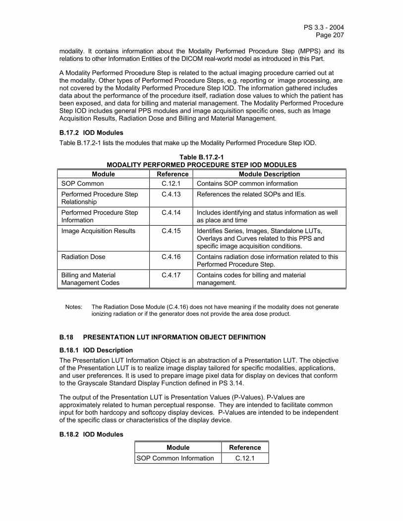
PS 3.3 - 2004 Page 207
modality. It contains information about the Modality Performed Procedure Step (MPPS) and its relations to other Information Entities of the DICOM real-world model as introduced in this Part.
A Modality Performed Procedure Step is related to the actual imaging procedure carried out at the modality. Other types of Performed Procedure Steps, e.g. reporting or image processing, are not covered by the Modality Performed Procedure Step IOD. The information gathered includes data about the performance of the procedure itself, radiation dose values to which the patient has been exposed, and data for billing and material management. The Modality Performed Procedure Step IOD includes general PPS modules and image acquisition specific ones, such as Image Acquisition Results, Radiation Dose and Billing and Material Management.
B.17.2 IOD Modules Table B.17.2-1 lists the modules that make up the Modality Performed Procedure Step IOD.
Table B.17.2-1 MODALITY PERFORMED PROCEDURE STEP IOD MODULES
Module Reference Module Description SOP Common C.12.1 Contains SOP common information Performed Procedure Step Relationship
C.4.13 References the related SOPs and IEs.
Performed Procedure Step Information
C.4.14 Includes identifying and status information as well as place and time
Image Acquisition Results
C.4.15 Identifies Series, Images, Standalone LUTs, Overlays and Curves related to this PPS and specific image acquisition conditions.
Radiation Dose C.4.16 Contains radiation dose information related to this Performed Procedure Step.
Billing and Material Management Codes
C.4.17 Contains codes for billing and material management.
Notes: The Radiation Dose Module (C.4.16) does not have meaning if the modality does not generate ionizing radiation or if the generator does not provide the area dose product.
B.18 PRESENTATION LUT INFORMATION OBJECT DEFINITION
B.18.1 IOD Description The Presentation LUT Information Object is an abstraction of a Presentation LUT. The objective of the Presentation LUT is to realize image display tailored for specific modalities, applications, and user preferences. It is used to prepare image pixel data for display on devices that conform to the Grayscale Standard Display Function defined in PS 3.14.
The output of the Presentation LUT is Presentation Values (P-Values). P-Values are approximately related to human perceptual response. They are intended to facilitate common input for both hardcopy and softcopy display devices. P-Values are intended to be independent of the specific class or characteristics of the display device. B.18.2 IOD Modules
Module Reference SOP Common Information C.12.1

PS 3.3 - 2004 Page 208
Presentation LUT Module C.11.4
B.19 PULL PRINT REQUEST INFORMATION OBJECT DEFINITION
B.19.1 IOD description The Pull Print Request IOD is an abstraction of a request to print one or more films, based on the information stored in the Stored Print IOD.
The Pull Print Request IOD contains print transaction related information (e.g. priority, number of copies) and a reference to the Stored Print IOD, which contains the print presentation parameters and references to images.
Note: The Film Session IOD is split into 2 IODs : - Stored Print IOD, containing layout information and references to images. It contains
information that remains invariant during subsequent re-prints (of the same film session). The Stored Print IOD may be archived.
- Print Request IOD, which contains information that may change during subsequent re-prints.
The E-R Model in Section A.1.2 depicts those components of the DICOM Information Model that are related to the Pull Print Request IOD.
B.19.2 IOD module table Table B.19-1
PULL PRINT REQUEST IOD MODULES Module Reference Usage
Print Request C.13.12 M SOP Common Information C.12.1 M
B.20 PRINTER CONFIGURATION INFORMATION OBJECT DEFINITION
B.20.1 IOD Description The Printer Configuration IOD describes key imaging characteristics of the printer.
B.20.2 IOD Modules Table B.20-1
Printer Configuration IOD Modules Module Reference Module Description
SOP Common C.12.1 Contains SOP Common Information Printer C13.9 Contains information about the
printer Printer Configuration C.13.13 Contains Printer Configuration
Information

PS 3.3 - 2004 Page 209
B.21 BASIC PRINT IMAGE OVERLAY BOX INFORMATION OBJECT DEFINITION
B.21.1 IOD Description The Basic Print Image Overlay Box IOD is an abstraction of the presentation of an image overlay in a basic image box. It contains the overlay pixel data to be printed on the image. A single overlay plane is supported. Overlays may be printed on both color and grayscale images. However, printing of the overlay pixels is only supported in black or white. B.21.2 IOD Modules
Module Reference SOP Common Information C.12.1 Basic Print Image Overlay Box Module C.9.5
B.22 GENERAL PURPOSE SCHEDULED PROCEDURE STEP INFORMATION OBJECT DEFINITION
B.22.1 IOD Description A "General Purpose Scheduled Procedure Step Information Object Definition" is an abstraction of the information that describes the scheduled activities, conditions and status of a scheduled procedure step. It contains information about the General Purpose Scheduled Procedure Step ( GP-SPS) and its relations to other Information Entities of the DICOM real-world model as introduced in PS 3.3.
A General Purpose Scheduled Procedure Step is related to one of the steps to be performed in response to the Requested Procedure.
B.22.2 IOD Modules Table B.22.2-1 lists the modules that make up the General Purpose Scheduled Procedure Step IOD.
Table B.22.2-1 GENERAL PURPOSE SCHEDULED PROCEDURE STEP IOD MODULES
Module Reference Module Description SOP Common C.12.1 Contains SOP common information General Purpose Scheduled Procedure Step Relationship
C.4.18 References the related SOPs and IEs.
General Purpose Scheduled Procedure Step Information
C.4.19 Includes identifying and status information as well as place and time
B.23 GENERAL PURPOSE PERFORMED PROCEDURE STEP INFORMATION OBJECT DEFINITION
B.23.1 IOD Description A "General Purpose Performed Procedure Step Information Object Definition" is an abstraction of the information that describes the activities, conditions and results of a procedure step performed on a performing device. It contains information about the General Purpose Performed Procedure Step ( GP-PPS) and its relations to other Information Entities of the DICOM real-world model as introduced in PS 3.3.
A General Purpose Performed Procedure Step is related to the procedure scheduled to be performed. The information gathered at the performing device includes data about the perfor-

PS 3.3 - 2004 Page 210
mance of the procedure step itself and the results. The General Purpose Performed Procedure Step IOD includes general GP-PPS modules and a specific one for the created results, the General Purpose Results.
B.23.2 IOD Modules Table B.21.2-1 lists the modules that make up the General Purpose Performed Procedure Step IOD.
Table B.23.2-1 GENERAL PURPOSE PERFORMED PROCEDURE STEP IOD MODULES
Module Reference Module Description SOP Common C.12.1 Contains SOP common information General Purpose Performed Procedure Step Relationship
C.4.20 References the related SOPs and IEs.
General Purpose Performed Procedure Step Information
C.4.21 Includes identifying and status information as well as place and time
General Purpose Results C.4.22 Identifies Results related to this GP-PPS.
B.24 INSTANCE AVAILABILITY NOTIFICATION INFORMATION OBJECT DEFINITION
B.24.1 IOD Description An "Instance Availability Notification Information Object Definition" is a summary of the information that describes the availability of a set of Composite Instances.
B.24.2 IOD Modules Table B.24.2-1 lists the modules, which make up the Instance Availability Notification IOD.
Table B.24.2-1 INSTANCE AVAILABILITY NOTIFICATION IOD MODULES
Module Reference Module Description SOP Common C.12.1 Contains SOP common information Instance Availability Notification C.4.23 References the related SOPs and IEs.
B.25 MEDIA CREATION MANAGEMENT INFORMATION OBJECT DEFINITION
B.25.1 IOD Description A "Media Creation Management Information Object Definition" is an abstraction of the information that describes the attributes and the status of a media creation request.
B.25.2 IOD Modules Table B.25.2-1 lists the modules that make up the Media Creation Management IOD.
Table B.25.2-1 MEDIA CREATION MANAGEMENT IOD MODULES
Module Reference Module Description SOP Common C.12.1 Contains SOP common information Media Creation Management C.22.1 Contains references to the SOP instances to be used
for this media creation request, and the information about its status.
PS 3.3 - 2004 Page 211
Annex C INFORMATION MODULE DEFINITIONS (NORMATIVE)
C.1 ELEMENTS OF A MODULE DEFINITION
A Module Definition is composed of the following Sections
a. Module Description
b. Module Definition
c. Attribute Description (Optional)
Sections C.1.1 through C.1.3 define the requirements of a. through c. above.
C.1.1 Module Description This Section briefly describes the Module and references the Module Definition.
C.1.2 Module Definition This Section contains a table that enumerates each Attribute contained in the Module. For each Attribute in the table the following information is given:
a. Attribute Name (see C.1.2.1)
b. Data Element Tag (see C.1.2.2)
c. Type Designation (see C.1.2.3)
d. Attribute Definition (see C.1.2.4)
C.1.2.1 Attribute Name This name shall be used whenever referencing the Attribute. This name shall also identify the Attribute in PS 3.6.
C.1.2.2 Attribute Tag Each Attribute has a tag that uniquely identifies the Attribute (also used for encoding into a Data Set - see PS 3.5). This tag also serves as an index into the Data Dictionary of PS 3.6.
C.1.2.3 Type Designation Each Attribute contained in a Module referenced by a Composite IOD defines a Type designation that indicates if a specific Attribute is required for all DIMSE operations/notifications associated with a SOP Class using this Module. PS 3.5 defines a choice of generic Type designations available for DICOM Attributes.
Note: The Type designation specified is generally determined by the value most appropriate for the C-STORE DIMSE Service.
The Type designation given in a Module is a default value and as such may be overridden by an IOD referencing the Module. Some Attributes may also be contained in more than one Module for the IOD. In that case, the Type designation applicable for the Attribute of the specific IOD is the lowest Type value (e.g. if type 2 is specified in one Module and type 3 in another, then type 2 shall apply), unless explicitly stated by the Attribute description.
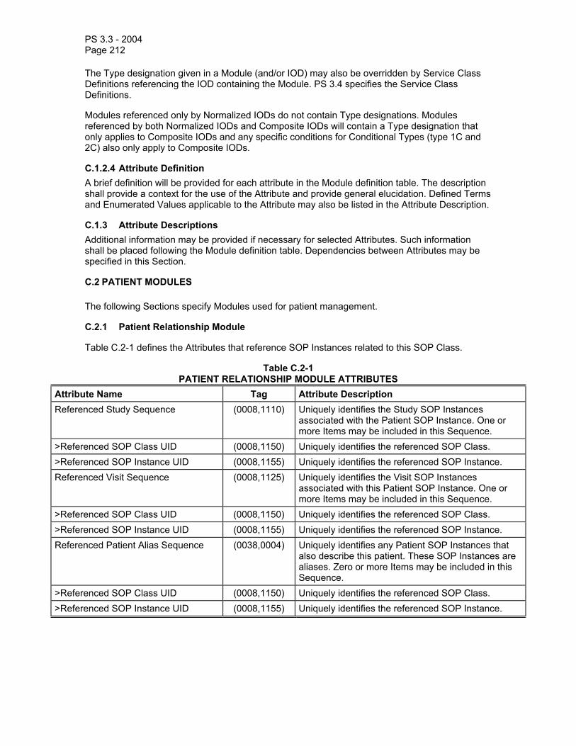
PS 3.3 - 2004 Page 212
The Type designation given in a Module (and/or IOD) may also be overridden by Service Class Definitions referencing the IOD containing the Module. PS 3.4 specifies the Service Class Definitions.
Modules referenced only by Normalized IODs do not contain Type designations. Modules referenced by both Normalized IODs and Composite IODs will contain a Type designation that only applies to Composite IODs and any specific conditions for Conditional Types (type 1C and 2C) also only apply to Composite IODs.
C.1.2.4 Attribute Definition A brief definition will be provided for each attribute in the Module definition table. The description shall provide a context for the use of the Attribute and provide general elucidation. Defined Terms and Enumerated Values applicable to the Attribute may also be listed in the Attribute Description.
C.1.3 Attribute Descriptions Additional information may be provided if necessary for selected Attributes. Such information shall be placed following the Module definition table. Dependencies between Attributes may be specified in this Section.
C.2 PATIENT MODULES
The following Sections specify Modules used for patient management.
C.2.1 Patient Relationship Module
Table C.2-1 defines the Attributes that reference SOP Instances related to this SOP Class.
Table C.2-1 PATIENT RELATIONSHIP MODULE ATTRIBUTES
Attribute Name Tag Attribute Description Referenced Study Sequence (0008,1110) Uniquely identifies the Study SOP Instances
associated with the Patient SOP Instance. One or more Items may be included in this Sequence.
>Referenced SOP Class UID (0008,1150) Uniquely identifies the referenced SOP Class. >Referenced SOP Instance UID (0008,1155) Uniquely identifies the referenced SOP Instance. Referenced Visit Sequence (0008,1125) Uniquely identifies the Visit SOP Instances
associated with this Patient SOP Instance. One or more Items may be included in this Sequence.
>Referenced SOP Class UID (0008,1150) Uniquely identifies the referenced SOP Class. >Referenced SOP Instance UID (0008,1155) Uniquely identifies the referenced SOP Instance. Referenced Patient Alias Sequence (0038,0004) Uniquely identifies any Patient SOP Instances that
also describe this patient. These SOP Instances are aliases. Zero or more Items may be included in this Sequence.
>Referenced SOP Class UID (0008,1150) Uniquely identifies the referenced SOP Class. >Referenced SOP Instance UID (0008,1155) Uniquely identifies the referenced SOP Instance.

PS 3.3 - 2004 Page 213
C.2.2 Patient Identification Module
Table C.2-2 defines the Attributes relevant to identifying a patient.
Table C.2-2 PATIENT IDENTIFICATION MODULE ATTRIBUTES
Attribute Name Tag Attribute Description Patient's Name (0010,0010) Patient's full name Patient ID (0010,0020) Primary hospital identification number or code for the
patient. Issuer of Patient ID (0010,0021) Identifier of the Assigning Authority (system,
organization, agency, or department) that issued the Patient ID.
Note: Issuer of Patient ID (0010,0021) is equivalent to HL7 v2 PID-3 component 4.
Other Patient IDs (0010,1000) Other identification numbers or codes used to identify the patient.
Other Patient Names (0010,1001) Other names used to identify the patient. Patient's Birth Name (0010,1005) Patient's birth name. Patient's Mother's Birth Name (0010,1060) Birth name of patient's mother. Medical Record Locator (0010,1090) An identifier used to find the patient's existing
medical record (e.g. film jacket).

PS 3.3 - 2004 Page 214
C.2.3 Patient Demographic Module
Table C.2-3 defines the Attributes relevant to generally describing a patient.
Table C.2-3 PATIENT DEMOGRAPHIC MODULE ATTRIBUTES
Attribute Name Tag Attribute Description Patient's Age (0010,1010) Age of the Patient. Occupation (0010,2180) Occupation of the Patient. Confidentiality Constraint on Patient Data Description
(0040,3001) Special indication to the modality operator about confidentiality of patient information (e.g., that he should not use the patients name where other patients are present).
Patient’s Birth Date (0010,0030) Date of birth of the named patient Patient’s Birth Time (0010,0032) Time of birth of the named patient Patient's Sex (0010,0040) Sex of the named patient. Enumerated Values:
M = male F = female O = other
Patient's Insurance Plan Code Sequence
(0010,0050) A sequence that conveys the patient's insurance plan. Zero or more Items may be included in this Sequence.
>Include ‘Code Sequence Macro’ Table 8.8-1 No Baseline Context ID is defined.
Patient’s Primary Language Code Sequence
(0010,0101) The languages that can be used to communicate with the patient. Zero or more Items may be included in the sequence. The sequence items are ordered by preference (most preferred language to least preferred language).
> Include Code Sequence Macro Table 8.8-2 Baseline Context ID is CID 5000 - Languages. > Patient’s Primary Language Code Modifier Sequence
(0010,0102) A modifer for a Patient’s Primary Language. Can be used to specify a national language variant. Exactly one Item may be included in the sequence.
>> Include Code Sequence Macro Table 8.8-2 Baseline Context ID is CID 5001 - Countries. Patient's Size (0010,1020) Patient's height or length in meters Patient's Weight (0010,1030) Weight of the patient in kilograms Patient’s Address (0010,1040) Legal address of the named patient Military Rank (0010,1080) Military rank of patient Branch of Service (0010,1081) Branch of the military. The country allegiance may
also be included (e.g. U.S. Army). Country of Residence (0010,2150) Country in which patient currently resides Region of Residence (0010,2152) Region within patient's country of residence Patient’s Telephone Numbers (0010,2154) Telephone numbers at which the patient can be
reached Ethnic Group (0010,2160) Ethnic group or race of patient

PS 3.3 - 2004 Page 215
Patient's Religious Preference (0010,21F0) The religious preference of the patient Patient Comments (0010,4000) User-defined comments about the patient
Note: The language codes specified in CID 5000, used in Patient’s Primary Language Code Sequence (0010,0101), optionally allow the encoding of the country of language in the code value for the language. Encoding of the country of language in a subsidiary Patient’s Primary Language Code Modifier Sequence (0010,0102) is allowed for backward compatibility with previous editions of the Standard.
C.2.4 Patient Medical Module
Table C.2-4 defines the Attributes relevant to a patient's medical state or history.
Table C.2-4 PATIENT MEDICAL MODULE ATTRIBUTES
Attribute Name Tag Attribute Description Medical Alerts (0010,2000) Conditions to which medical staff should be alerted
(e.g. contagious condition, drug allergies, etc.) Contrast Allergies (0010,2110) Description of prior reaction to contrast agents. Smoking Status (0010,21A0) Indicates whether patient smokes.
Enumerated Values: YES NO UNKNOWN
Additional Patient History (0010,21B0) Additional information about the patient's medical history
Pregnancy Status (0010,21C0) Describes pregnancy state of patient. Enumerated Values: 0001 = not pregnant 0002 = possibly pregnant 0003 = definitely pregnant 0004 = unknown
Last Menstrual Date (0010,21D0) Date of onset of last menstrual period Special Needs (0038,0050) Medical and social needs (e.g. wheelchair, oxygen,
non-English-speaking, etc.) Patient State (0038,0500) Description of patient state (comatose, disoriented,
vision impaired, etc.)

PS 3.3 - 2004 Page 216
C.3 VISIT MODULES
The following Sections specify Modules relevant to a real world patient visit.
C.3.1 Visit Relationship Module
Table C.3-1 defines the Attributes that reference SOP Instances related to this SOP Class.
Table C.3-1 VISIT RELATIONSHIP MODULE ATTRIBUTES
Attribute Name Tag Attribute Description Referenced Study Sequence (0008,1110) Uniquely identifies the Study SOP Instances
associated with the Visit SOP Instance. One or more Items may be included in this Sequence.
>Referenced SOP Class UID (0008,1150) Uniquely identifies the referenced SOP Class. >Referenced SOP Instance UID (0008,1155) Uniquely identifies the referenced SOP Instance. Referenced Patient Sequence (0008,1120) Uniquely identifies the Patient SOP Instance that
relates to the Visit SOP Instance. Only a single Item shall be permitted in this Sequence.
>Referenced SOP Class UID (0008,1150) Uniquely identifies the referenced SOP Class. >Referenced SOP Instance UID (0008,1155) Uniquely identifies the referenced SOP Instance.
C.3.2 Visit Identification Module
Table C.3-2 defines the Attributes relevant to identifying a visit.
Table C.3-2 VISIT IDENTIFICATION MODULE ATTRIBUTES
Attribute Name Tag Attribute Description Institution Name (0008,0080) Institution where the equipment is located Institution Address (0008,0081) Mailing Address of the institution where the
equipment is located Institution Code Sequence (0008,0082) A sequence that conveys the healthcare facility
identification. Only a single Item shall be permitted in this Sequence.
>Include ‘Code Sequence Macro’ Table 8.8-1 No Baseline Context ID is defined.
Admission ID (0038,0010) Identification number of the visit as assigned by the healthcare provider
Issuer of Admission ID (0038,0011) Name of healthcare provider which issued the Admission ID

PS 3.3 - 2004 Page 217
C.3.3 Visit Status Module
Table C.3-3 defines the Attributes relevant to the patient's stay with the healthcare provider.
Table C.3-3 VISIT STATUS MODULE ATTRIBUTES
Attribute Name Tag Attribute Description Visit Status ID (0038,0008) Identifies the state of the visit. Defined Terms:
CREATED = Created but not yet scheduled SCHEDULED = Scheduled but not yet admitted ADMITTED = Patient admitted to institution DISCHARGED = Patient Discharged
Current Patient Location (0038,0300) Describes the current known location of the patient Patient’s Institution Residence (0038,0400) Primary location where patient resides (ward, floor,
room, etc. or outpatient) Visit Comments (0038,4000) User-defined comments about the visit
C.3.4 Visit Admission Module
Table C.3-4 defines the Attributes relevant to admitting a patient during a visit.
Table C.3-4 VISIT ADMISSION MODULE ATTRIBUTES
Attribute Name Tag Attribute Description Referring Physician's Name (0008,0090) Patient's primary referring physician for this visit Referring Physician's Address (0008,0092) Referring physician's address Referring Physician's Telephone Numbers
(0008,0094) Referring physician's telephone numbers
Referring Physician Identification Sequence
(0008,0096) Identification of the patient's referring physician. Only a single item shall be permitted in this sequence.
>Include ‘Person Identification Macro’ Table 10-1 Admitting Diagnoses Description (0008,1080) Description of admitting diagnosis (diagnoses). Admitting Diagnoses Code Sequence (0008,1084) A sequence that conveys the admitting diagnosis
(diagnoses). One or more Items may be included in this Sequence.
>Include ‘Code Sequence Macro’ Table 8.8-1 No Baseline Context ID is defined.
Route of Admissions (0038,0016) Mode of admission: emergency, normal Admitting Date (0038,0020) Date patient visit began Admitting Time (0038,0021) Time patient visit began

PS 3.3 - 2004 Page 218
C.3.5 Visit Discharge Module
Table C.3-5 defines the Attributes relevant to the discharging of a patient from a visit.
Table C.3-5 VISIT DISCHARGE MODULE ATTRIBUTES
Attribute Name Tag Attribute Description Discharge Date (0038,0030) Date patient visit ended or is scheduled to end. Discharge Time (0038,0032) Time patient visit ended or is scheduled to end. Discharge Diagnosis Description (0038,0040) Institution-generated description of discharge
diagnosis. Discharge Diagnosis Code Sequence (0038,0044) A sequence that conveys the discharge diagnosis.
One or more Items may be included in this Sequence.
>Include ‘Code Sequence Macro’ Table 8.8-1 No Baseline Context ID is defined.
C.3.6 Visit Scheduling Module
Table C.3-6 defines the Attributes relevant to the scheduling of a patient visit.
Table C.3-6 VISIT SCHEDULING MODULE ATTRIBUTES
Attribute Name Tag Attribute Description Scheduled Admission Date (0038,001A) Date patient visit is scheduled to start Scheduled Admission Time (0038,001B) Time patient visit is scheduled to start Scheduled Discharge Date (0038,001C) Date patient visit is scheduled to end Scheduled Discharge Time (0038,001D) Time patient visit is scheduled to end Scheduled Patient Institution Residence
(0038,001E) Scheduled location where patient is to reside (ward, floor, room, etc. or outpatient)
C.4 STUDY MODULES
The following Sections specify Modules relevant to a real world diagnostic imaging study performed on a patient.

PS 3.3 - 2004 Page 219
C.4.1 Study Relationship Module Table C.4-1 defines the Attributes that reference SOP Instances Subordinate or Superior to this SOP Class in the Naming Hierarchy.
Table C.4-1 STUDY RELATIONSHIP MODULE ATTRIBUTES
Attribute Name Tag Attribute Description Referenced Visit Sequence (0008,1125) Uniquely identifies the Visit SOP Instances
associated with this Study SOP Instance. One or more Items may be included in this Sequence.
>Referenced SOP Class UID (0008,1150) Uniquely identifies the referenced SOP Class. >Referenced SOP Instance UID (0008,1155) Uniquely identifies the referenced SOP Instance. Referenced Patient Sequence (0008,1120) Uniquely identifies the Patient SOP Instance that
relates to the Study SOP Instance. Only a single Item shall be permitted in this Sequence.
>Referenced SOP Class UID (0008,1150) Uniquely identifies the referenced SOP Class. >Referenced SOP Instance UID (0008,1155) Uniquely identifies the referenced SOP Instance. Referenced Results Sequence (0008,1100) Uniquely identifies the results SOP Instance for
which the interpretation SOP Instance applies. Zero or more Items may be included in this Sequence.
>Referenced SOP Class UID (0008,1150) Uniquely identifies the referenced SOP Class. >Referenced SOP Instance UID (0008,1155) Uniquely identifies the referenced SOP Instance. Referenced Performed Procedure Step Sequence
(0008,1111) Uniquely identifies the Performed Procedure Step SOP Instances to which the Study SOP Instance is related (e.g. a Modality or General-Purpose Performed Procedure Step SOP Instance or Study Component SOP Instance).
>Referenced SOP Class UID (0008,1150) Uniquely identifies the referenced SOP Class. >Referenced SOP Instance UID (0008,1155) Uniquely identifies the referenced SOP Instance. Study Instance UID (0020,000D) Unique identifier for the Study Accession Number (0008,0050) A RIS generated number that identifies the order for
the Study.
C.4.2 Study Identification Module
Table C.4-2 defines the Attributes relevant to identifying a study.
Table C.4-2 STUDY IDENTIFICATION MODULE ATTRIBUTES
Attribute Name Tag Attribute Description Study ID (0020,0010) User or equipment generated Study identifier Study ID Issuer (0032,0012) Name of healthcare provider that issued the Study IDOther Study Numbers (0020,1070) Other identifiers assigned to study by institution

PS 3.3 - 2004 Page 220
C.4.3 Study Classification Module
Table C.4-3 defines the Attributes relevant to classifying a study.
Table C.4-3 STUDY CLASSIFICATION MODULE ATTRIBUTES
Attribute Name Tag Attribute Description Study Status ID (0032,000A) Identifies the state of the study.
Enumerated Values: CREATED = Created but not yet scheduled SCHEDULED = Scheduled but not yet started ARRIVED = Patient Arrived but study not started STARTED = Started but not yet finished COMPLETED = Complete but image quality not verified VERIFIED = Complete and image quality verified READ = Read by the Physicians
Study Priority ID (0032,000C) Identifies the priority of the study. Enumerated values: LOW, MED, HIGH
Study Comments (0032,4000) User-defined comments about the study
C.4.4 Study Scheduling Module
Table C.4-4 defines the Attributes relevant to scheduling a study.
Table C.4-4 STUDY SCHEDULING MODULE ATTRIBUTES
Attribute Name Tag Attribute Description Scheduled Study Start Date (0032,1000) Date on which the study is scheduled to start Scheduled Study Start Time (0032,1001) Time at which the study is scheduled to start Scheduled Study Stop Date (0032,1010) Date on which the patient examination for the study
is scheduled to end Scheduled Study Stop Time (0032,1011) Time at which the patient examination for the study is
scheduled to end Scheduled Study Location (0032,1020) User-defined location at which the study will be
performed Scheduled Study Location AE Title (0032,1021) A list of Application Entity Title(s) of the location at
which the study will be performed Reason for Study (0032,1030) Describes the reason for performing study Requesting Physician (0032,1032) Name of the physician who requested the study Requesting Physician Identification Sequence
(0032,1031) Identification of the physician who requested the Imaging Service Request. Only a single item shall be permitted in this sequence.

PS 3.3 - 2004 Page 221
>Include ‘Person Identification Macro’ Table 10-1 Requesting Service (0032,1033) Institutional department where the request initiated. Requested Procedure Description (0032,1060) Institution-generated description or classification of
requested procedure Requested Procedure Code Sequence (0032,1064) A sequence that conveys the requested procedure.
One or more Items may be included in this Sequence.
>Include ‘Code Sequence Macro’ Table 8.8-1 No Baseline Context ID is defined.
Requested Contrast Agent (0032,1070) Contrast agent requested for use in the procedure
C.4.5 Study Acquisition Module Table C.4-5 defines the Attributes relevant to acquiring a study.
Table C.4-5 STUDY ACQUISITION MODULE ATTRIBUTES
Attribute Name Tag Attribute Description Study Arrival Date (0032,1040) Date that patient arrived at study check-in location Study Arrival Time (0032,1041) Time at which patient arrived at study check-in
location Study Date (0008,0020) Date on which the acquisition of the study
information was started Study Time (0008,0030) Time at which the acquisition of the study
information was started Study Completion Date (0032,1050) Date on which the acquisition of study information
was completed Study Completion Time (0032,1051) Time at which the acquisition of study information
was completed Study Verified Date (0032,0032) Date on which the image quality for the patient
examination was verified Study Verified Time (0032,0033) Time at which the image quality for the patient
examination was verified Modalities in Study (0008,0061) This Attribute may take one or more of the values
defined for Modality (0008,0060) Series in Study (0020,1000) Number of series in the study Acquisitions in Study (0020,1004) Number of image data acquisitions used in
performing the study
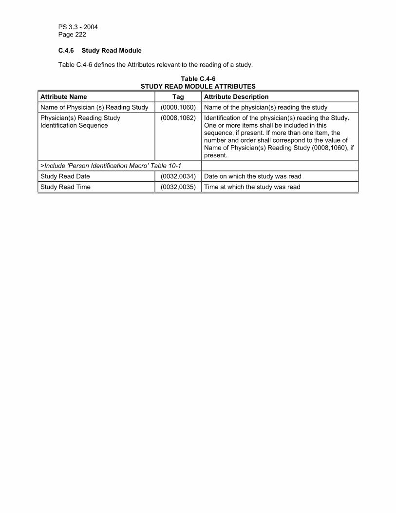
PS 3.3 - 2004 Page 222
C.4.6 Study Read Module
Table C.4-6 defines the Attributes relevant to the reading of a study.
Table C.4-6 STUDY READ MODULE ATTRIBUTES
Attribute Name Tag Attribute Description Name of Physician (s) Reading Study (0008,1060) Name of the physician(s) reading the study Physician(s) Reading Study Identification Sequence
(0008,1062) Identification of the physician(s) reading the Study. One or more items shall be included in this sequence, if present. If more than one Item, the number and order shall correspond to the value of Name of Physician(s) Reading Study (0008,1060), if present.
>Include ‘Person Identification Macro’ Table 10-1 Study Read Date (0032,0034) Date on which the study was read Study Read Time (0032,0035) Time at which the study was read

PS 3.3 - 2004 Page 223
C.4.7 Study Component Module
Table C.4-7 defines the Attributes relevant to the study component.
Table C.4-7 STUDY COMPONENT MODULE ATTRIBUTES
Attribute Name Tag Attribute Description Study ID (0020,0010) User or equipment generated Study identifier Study Instance UID (0020,000D) Unique identifier for the Study Referenced Series Sequence (0008,1115) Sequence of Repeating Items where each Item
includes the Attributes of a Series. Zero or more Items may be included in this Sequence.
>Series Date (0008,0021) Date the Series started. >Series Time (0008,0031) Time the Series started. >Series Instance UID (0020,000E) Unique identifier of the Series. >Retrieve AE Title (0008,0054) Title of the DICOM Application Entity where the
Image(s) may be retrieved on the network. >Storage Media File-Set ID (0088,0130) The user or implementation specific human
readable identifier that identifies the Storage Media on which the Image(s) reside.
>Storage Media File-Set UID (0088,0140) Uniquely identifies the Storage Media on which the Image(s) reside.
>Referenced Image Sequence (0008,1140) Sequence of Repeating Items where each Item provides reference to a set of Image SOP Class/SOP Instance pairs that are contained in the Series identified by the Series Instance UID (0020,000E). One or more Items may be included in this Sequence.
>>Referenced SOP Class UID (0008,1150) Uniquely identifies the referenced SOP Class. This Attribute is used only if Images may be retrieved as Single Image SOP Classes.
>>Referenced SOP Instance UID (0008,1155) Uniquely identifies the referenced SOP Instance. This Attribute is used only if Images may be retrieved as Single Image SOP Classes.
>>Retrieve AE Title (0008,0054) Title of the DICOM Application Entity where the Image(s) may be retrieved on the network.
>>Storage Media File-Set ID (0088,0130) The user or implementation specific human readable identifier that identifies the Storage Media on which the Image(s) reside.
>>Storage Media File-Set UID (0088,0140) Uniquely identifies the Storage Media on which the Image(s) reside.
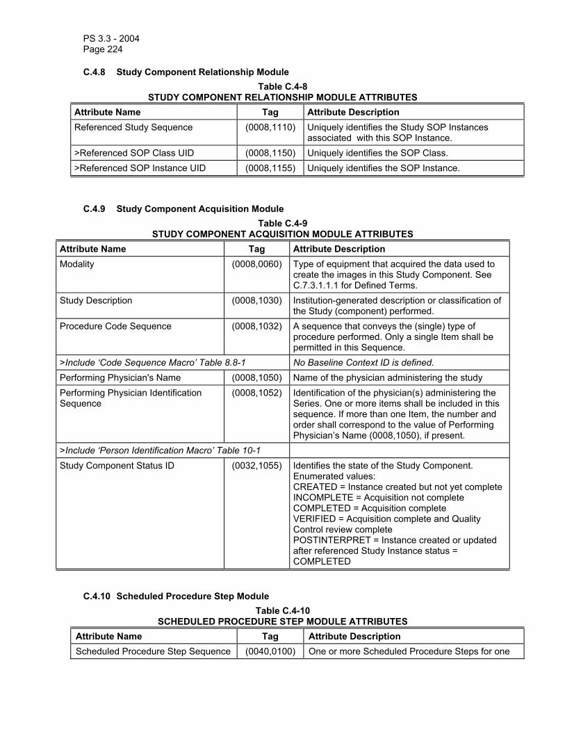
PS 3.3 - 2004 Page 224
C.4.8 Study Component Relationship Module Table C.4-8
STUDY COMPONENT RELATIONSHIP MODULE ATTRIBUTES Attribute Name Tag Attribute Description Referenced Study Sequence (0008,1110) Uniquely identifies the Study SOP Instances
associated with this SOP Instance. >Referenced SOP Class UID (0008,1150) Uniquely identifies the SOP Class. >Referenced SOP Instance UID (0008,1155) Uniquely identifies the SOP Instance.
C.4.9 Study Component Acquisition Module Table C.4-9
STUDY COMPONENT ACQUISITION MODULE ATTRIBUTES Attribute Name Tag Attribute Description Modality (0008,0060) Type of equipment that acquired the data used to
create the images in this Study Component. See C.7.3.1.1.1 for Defined Terms.
Study Description (0008,1030) Institution-generated description or classification of the Study (component) performed.
Procedure Code Sequence (0008,1032) A sequence that conveys the (single) type of procedure performed. Only a single Item shall be permitted in this Sequence.
>Include ‘Code Sequence Macro’ Table 8.8-1 No Baseline Context ID is defined. Performing Physician's Name (0008,1050) Name of the physician administering the study Performing Physician Identification Sequence
(0008,1052) Identification of the physician(s) administering the Series. One or more items shall be included in this sequence. If more than one Item, the number and order shall correspond to the value of Performing Physician’s Name (0008,1050), if present.
>Include ‘Person Identification Macro’ Table 10-1 Study Component Status ID (0032,1055) Identifies the state of the Study Component.
Enumerated values: CREATED = Instance created but not yet completeINCOMPLETE = Acquisition not complete COMPLETED = Acquisition complete VERIFIED = Acquisition complete and Quality Control review complete POSTINTERPRET = Instance created or updated after referenced Study Instance status = COMPLETED
C.4.10 Scheduled Procedure Step Module Table C.4-10
SCHEDULED PROCEDURE STEP MODULE ATTRIBUTES Attribute Name Tag Attribute Description Scheduled Procedure Step Sequence (0040,0100) One or more Scheduled Procedure Steps for one
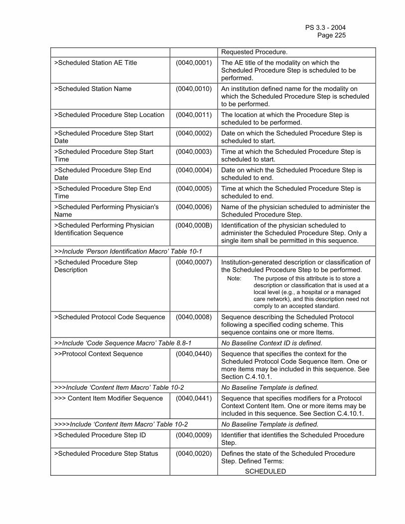
PS 3.3 - 2004 Page 225
Requested Procedure. >Scheduled Station AE Title (0040,0001) The AE title of the modality on which the
Scheduled Procedure Step is scheduled to be performed.
>Scheduled Station Name (0040,0010) An institution defined name for the modality on which the Scheduled Procedure Step is scheduled to be performed.
>Scheduled Procedure Step Location (0040,0011) The location at which the Procedure Step is scheduled to be performed.
>Scheduled Procedure Step Start Date
(0040,0002) Date on which the Scheduled Procedure Step is scheduled to start.
>Scheduled Procedure Step Start Time
(0040,0003) Time at which the Scheduled Procedure Step is scheduled to start.
>Scheduled Procedure Step End Date
(0040,0004) Date on which the Scheduled Procedure Step is scheduled to end.
>Scheduled Procedure Step End Time
(0040,0005) Time at which the Scheduled Procedure Step is scheduled to end.
>Scheduled Performing Physician's Name
(0040,0006) Name of the physician scheduled to administer the Scheduled Procedure Step.
>Scheduled Performing Physician Identification Sequence
(0040,000B) Identification of the physician scheduled to administer the Scheduled Procedure Step. Only a single item shall be permitted in this sequence.
>>Include ‘Person Identification Macro’ Table 10-1 >Scheduled Procedure Step Description
(0040,0007) Institution-generated description or classification of the Scheduled Procedure Step to be performed.
Note: The purpose of this attribute is to store a description or classification that is used at a local level (e.g., a hospital or a managed care network), and this description need not comply to an accepted standard.
>Scheduled Protocol Code Sequence (0040,0008) Sequence describing the Scheduled Protocol following a specified coding scheme. This sequence contains one or more Items.
>>Include ‘Code Sequence Macro’ Table 8.8-1 No Baseline Context ID is defined. >>Protocol Context Sequence (0040,0440) Sequence that specifies the context for the
Scheduled Protocol Code Sequence Item. One or more items may be included in this sequence. See Section C.4.10.1.
>>>Include ‘Content Item Macro’ Table 10-2 No Baseline Template is defined. >>> Content Item Modifier Sequence (0040,0441) Sequence that specifies modifiers for a Protocol
Context Content Item. One or more items may be included in this sequence. See Section C.4.10.1.
>>>>Include ‘Content Item Macro’ Table 10-2 No Baseline Template is defined. >Scheduled Procedure Step ID (0040,0009) Identifier that identifies the Scheduled Procedure
Step. >Scheduled Procedure Step Status (0040,0020) Defines the state of the Scheduled Procedure
Step. Defined Terms: SCHEDULED

PS 3.3 - 2004 Page 226
ARRIVED >Comments on the Scheduled Procedure Step
(0040,0400) User-defined comments on the Scheduled Procedure Step. Note: The Comments attribute is intended to
transmit non-structured information, which can be displayed to the operator of the Modality.
>Modality (0008,0060) Source equipment for the image. See Section C.7.3.1.1.1 for Defined Terms.
>Requested Contrast Agent (0032,1070) Contrast agent requested for use in the Scheduled Procedure Step.
>Pre-Medication (0040,0012) Medication to be administered at the beginning of the Scheduled Procedure Step, e.g. Nuclear Medicine radiopharmaceutical.
C.4.10.1 Protocol Context Sequence The Protocol Context Sequence (0040,0440) allows the specification of parameters that further qualify the scheduled protocol, provided through a set of generic name/value pairs of context Content Items.
Note: This allows the specification of clinical, acquisition, or procedural qualifiers for the scheduled protocol, such as a specific body part, imaging technique, or parameters of a preparatory event (e.g., radionuclide injection). Specific uses of this Sequence may be documented in a Template defined in accordance with PS3.16.
C.4.11 Requested Procedure Module
Table C.4-11 REQUESTED PROCEDURE MODULE ATTRIBUTES
Attribute Name Tag Attribute Description Requested Procedure ID (0040,1001) Identifier that identifies the Requested Procedure
in the Imaging Service Request. Reason for the Requested Procedure (0040,1002) Reason for requesting this imaging procedure.
Note: This reason is more specific to the requested procedure than the reason mentioned in the imaging service request (0040,2001).
Requested Procedure Comments (0040,1400) User-defined comments on the Requested Procedure.
Reason for Requested Procedure Code Sequence
(0040,100A) Coded Reason for requesting this procedure.
>Include ‘Code Sequence Macro’ Table 8.8-1 No Baseline Context ID is defined. Requested Procedure Code Sequence
(0032,1064) A sequence that conveys the Requested Procedure of one Procedure Type.
>Include ‘Code Sequence Macro’ Table 8.8-1 No Baseline Context ID is defined. Study Instance UID (0020,000D) Unique identifier to be used to identify the Study Referenced Study Sequence (0008,1110) Uniquely identifies the Study SOP Instances
associated with this SOP Instance. >Referenced SOP Class UID (0008,1150) Uniquely identifies the SOP Class.

PS 3.3 - 2004 Page 227
>Referenced SOP Instance UID (0008,1155) Uniquely identifies the SOP Instance. Requested Procedure Description (0032,1060) Institution-generated administrative description or
classification of Requested Procedure Requested Procedure Priority (0040,1003) Requested Procedure Type Urgency. Defined
Terms: STAT, HIGH, ROUTINE, MEDIUM, LOW
Patient Transport Arrangements (0040,1004) Mode of transportation of the patient to the location of examination.
Requested Procedure Location (0040,1005) Physical location at which the Requested Procedure is to be performed.
Confidentiality Code (0040,1008) Confidentiality Constraints on the Requested Procedure by the party filling the order.
Reporting Priority (0040,1009) Requested Reporting Priority. Defined Terms: HIGH, ROUTINE, MEDIUM, LOW
Names of Intended Recipients of Results
(0040,1010) Names of the physicians, who are intended recipients of results.
Intended Recipients of Results Identification Sequence
(0040,1011) Identification of the physicians who are intended recipients of results. One or more items shall be included in this sequence. If more than one Item, the number and order shall correspond to the value of Names of Intended Recipients of Results (0040,1010), if present.
>>Include ‘Person Identification Macro’ Table 10-1
Note: Attributes (0040,1006) Placer Order Number/Procedure and (0040,1007) Filler Order Number/Procedure were previously defined in DICOM. They are now retired (See PS3.3 1998).
C.4.12 Imaging Service Request Module Table C.4-12
IMAGING SERVICE REQUEST MODULE ATTRIBUTES Attribute Name Tag Attribute Description
Imaging Service Request Comments (0040,2400) User-defined comments on the Imaging Service Request.
Note: The Comments attribute is intended to transmit non-structured information, which can be displayed to the operator of the equipment (e.g. Modality).
Requesting Physician (0032,1032) Name of the physician who requested the Imaging Service Request.
Requesting Physician Identification Sequence
(0032,1031) Identification of the physician who requested the Imaging Service Request. Only a single item shall be permitted in this sequence.
>Include ‘Person Identification Macro’ Table 10-1 Referring Physician's Name (0008,0090) Name of the patient's referring physician for this
Imaging Service Request.

PS 3.3 - 2004 Page 228
Referring Physician Identification Sequence
(0008,0096) Identification of the patient's referring physician. Only a single item shall be permitted in this sequence.
>Include ‘Person Identification Macro’ Table 10-1 Requesting Service (0032,1033) Institutional department where the request initiated.Accession Number (0008,0050) A departmental IS generated number that identifies
the order for the Imaging Service Request. Issue Date of Imaging Service Request
(0040,2004) Date on which the Imaging Service Request was issued by the requester.
Issue Time of Imaging Service Request
(0040,2005) Time at which the Imaging Service Request was issued by the requester.
Placer Order Number / Imaging Service Request
(0040,2016) The order number assigned to the Imaging Service Request by the party placing the order.
Filler Order Number / Imaging Service Request
(0040,2017) The order number assigned to the Imaging Service Request by the party filling the order.
Order entered by ... (0040,2008) The person who entered the Imaging Service Request into an Information System.
Order Enterer’s Location (0040,2009) The location at which the Imaging Service Request was entered.
Order Callback Phone Number (0040,2010) Telephone Number at which additional information can be retrieved.
Notes: 1. Attributes (0040,2016) and (0040,2017) Placer Order Number and Filler Order Number/Imaging Service Request are intended to convey the corresponding order numbers as defined in HL7, in the case where interoperability with an HL7 environment is the objective.
2. Attributes (0040,2001), (0040,2006) and (0040,2007) were previously defined in DICOM. They are now retired (See PS3.3 1998).
C.4.13 Performed Procedure Step Relationship Table C.4-13 specifies the Attributes used to reference other SOP Classes and other Information Entities of the DICOM real-world model as defined in Section 7.3.1.6.
Table C.4-13 PERFORMED PROCEDURE STEP RELATIONSHIP MODULE ATTRIBUTES Attribute Name Tag Attribute Description
Patient's Name (0010,0010) Patient's full legal name. Patient ID (0010,0020) Primary hospital identification number or code for the
patient. Issuer of Patient ID (0010,0021) Identifier of the Assigning Authority that issued the
Patient ID. Patient's Birth Date (0010,0030) Date of birth of the named patient Patient's Sex (0010,0040) Sex of the named Patient. Enumerated Values:
M = male F = female O = other
Referenced Patient Sequence (0008,1120) Uniquely identifies the Patient SOP Instance.

PS 3.3 - 2004 Page 229
>Referenced SOP Class UID (0008,1150) Uniquely identifies the referenced SOP Class. >Referenced SOP Instance UID
(0008,1155) Uniquely identifies the referenced SOP Instance.
Scheduled Step Attributes Sequence
(0040,0270) Sequence containing attributes that are related to the scheduling of the Procedure Step. The Sequence may have one or more Items.
>Study Instance UID (0020,000D) Unique identifier for the Study. >Referenced Study Sequence (0008,1110) Uniquely identifies the Study SOP Instance
associated with this Scheduled Procedure Step. This Sequence shall have only one Item.
>>Referenced SOP Class UID (0008,1150) Uniquely identifies the SOP Class. >>Referenced SOP Instance UID
(0008,1155) Uniquely identifies the SOP Instance.
>Accession Number (0008,0050) A departmental IS generated number that identifies the order for the Study.
>Placer Order Number/Imaging Service Request
(0040,2016) The order number assigned to the Imaging Service Request by the party placing the order.
>Filler Order Number/Imaging Service Request
(0040,2017) The order number assigned to the Imaging Service Request by the party filling the order.
>Requested Procedure ID (0040,1001) Identifier of the related Requested Procedure. >Requested Procedure Description
(0032,1060) Institution-generated administrative description or classification of Requested Procedure.
>Scheduled Procedure Step ID (0040,0009) Identifier of the related Scheduled Procedure Step. >Scheduled Procedure Step Description
(0040,0007)
Institution-generated description or classification of the Scheduled Procedure Step to be performed.
>Scheduled Protocol Code Sequence
(0040,0008) Sequence describing the Scheduled Protocol following a specific coding scheme. This sequence contains one or more Items.
>>Include ‘Code Sequence Macro’ Table 8.8-1 No Baseline Context ID is defined. >>Protocol Context Sequence (0040,0440) Sequence that specifies the context for the
Scheduled Protocol Code Sequence Item. One or more items may be included in this sequence. See Section C.4.10.1.
>>>Include ‘Content Item Macro’ Table 10-2 No Baseline Template is defined. >>> Content Item Modifier Sequence
(0040,0441) Sequence that specifies modifiers for a Protocol Context Content Item. One or more items may be included in this sequence. See Section C.4.10.1.
>>>>Include ‘Content Item Macro’ Table 10-2 No Baseline Template is defined.
Notes: 1. The patient information is included in order to relate the Modality Performed Procedure Step SOP Instance to the Study Management SOP Instance and other associated IODs in case the SCU (the modality) is unable to obtain or use the Study Instance UID created by the Information System. 2. Attributes (0040,2016) and (0040,2017) Placer Order Number and Filler Order Number/Imaging Service Request are intended to convey the corresponding order numbers as defined in HL7, in the case where interoperability with an HL7 environment is the objective.

PS 3.3 - 2004 Page 230
3. Attributes (0040,2006) and (0040,2007) were previously defined in DICOM. They are now retired (See PS3.3 1998).
4. Attributes (0040,1006) Placer Order Number/Procedure and (0040,1007) Filler Order Number/Procedure were previously defined in DICOM. They are now retired (See PS3.3 1998).
C.4.14 Performed Procedure Step Information Table C.4-14 defines the general attributes that may be used by all specific Procedure Steps.
Table C.4-14 PERFORMED PROCEDURE STEP INFORMATION MODULE ATTRIBUTES
Attribute Name Tag Attribute Description Performed Station AE Title (0040,0241) AE title of the modality on which the Performed
Procedure Step was performed. Performed Station Name (0040,0242) An institution defined name for the modality on which
the Performed Procedure Step was performed. Performed Location (0040,0243) Description of the location at which the Performed
Procedure Step was performed. Performed Procedure Step Start Date
(0040,0244) Date on which the Performed Procedure Step started.
Performed Procedure Step Start Time
(0040,0245) Time at which the Performed Procedure Step started.
Performed Procedure Step ID (0040,0253) User or equipment generated identifier of that part of a Procedure that has been carried out within this step.
Performed Procedure Step End Date
(0040,0250) Date on which the Performed Procedure Step ended.
Performed Procedure Step End Time
(0040,0251) Time at which the Performed Procedure Step ended.
Performed Procedure Step Status
(0040,0252) Contains the state of the Performed Procedure Step. Enumerated Values: IN PROGRESS = Started but not complete DISCONTINUED = Canceled or unsuccessfully terminated COMPLETED = Successfully completed
Performed Procedure Step Description
(0040,0254) Institution-generated description or classification of the Procedure Step that was performed.
Comments on the Performed Procedure Step
(0040,0280) User-defined comments on the Performed Procedure Step.
Performed Procedure Type Description
(0040,0255) A description of the type of procedure performed.
Procedure Code Sequence (0008,1032) A sequence that conveys the (single) type of procedure performed.
>Include ‘Code Sequence Macro’ Table 8.8-1 No Baseline Context ID is defined. Performed Procedure Step Discontinuation Reason Code Sequence
(0040,0281) The reason the Performed Procedure Step Status (0040,0252) was set to DISCONTINUED.
>Include ‘Code Sequence Macro’ Table 8.8-1 Defined Context ID is 9300.
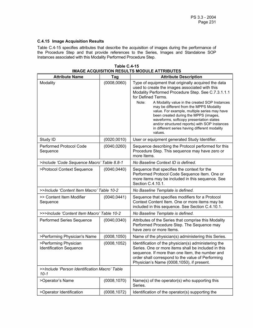
PS 3.3 - 2004 Page 231
C.4.15 Image Acquisition Results Table C.4-15 specifies attributes that describe the acquisition of images during the performance of the Procedure Step and that provide references to the Series, Images and Standalone SOP Instances associated with this Modality Performed Procedure Step.
Table C.4-15 IMAGE ACQUISITION RESULTS MODULE ATTRIBUTES
Attribute Name Tag Attribute Description Modality (0008,0060) Type of equipment that originally acquired the data
used to create the images associated with this Modality Performed Procedure Step. See C.7.3.1.1.1 for Defined Terms.
Note: A Modality value in the created SOP Instances may be different from the MPPS Modality value. For example, multiple series may have been created during the MPPS (images, waveforms, softcopy presentation states and/or structured reports) with SOP Instances in different series having different modality values.
Study ID (0020,0010) User or equipment generated Study Identifier. Performed Protocol Code Sequence
(0040,0260) Sequence describing the Protocol performed for this Procedure Step. This sequence may have zero or more Items.
>Include ‘Code Sequence Macro’ Table 8.8-1 No Baseline Context ID is defined. >Protocol Context Sequence (0040,0440) Sequence that specifies the context for the
Performed Protocol Code Sequence Item. One or more items may be included in this sequence. See Section C.4.10.1.
>>Include ‘Content Item Macro’ Table 10-2 No Baseline Template is defined. >> Content Item Modifier Sequence
(0040,0441) Sequence that specifies modifiers for a Protocol Context Content Item. One or more items may be included in this sequence. See Section C.4.10.1.
>>>Include ‘Content Item Macro’ Table 10-2 No Baseline Template is defined. Performed Series Sequence (0040,0340) Attributes of the Series that comprise this Modality
Performed Procedure Step. The Sequence may have zero or more Items.
>Performing Physician's Name (0008,1050) Name of the physician(s) administering this Series. >Performing Physician Identification Sequence
(0008,1052) Identification of the physician(s) administering the Series. One or more items shall be included in this sequence. If more than one Item, the number and order shall correspond to the value of Performing Physician’s Name (0008,1050), if present.
>>Include ‘Person Identification Macro’ Table 10-1
>Operator’s Name (0008,1070) Name(s) of the operator(s) who supporting this Series.
>Operator Identification (0008,1072) Identification of the operator(s) supporting the

PS 3.3 - 2004 Page 232
Sequence Series. One or more items shall be included in this sequence. If more than one Item, the number and order shall correspond to the value of Operator’s Name (0008,1070), if present.
>>Include ‘Person Identification Macro’ Table 10-1
>Protocol Name (0018,1030) User-defined description of the conditions under which the Series was performed.
Note: This attribute conveys series-specific protocol identification and may or may not be identical to the one presented in the Performed Protocol Code Sequence (0040,0260).
>Series Instance UID (0020,000E) Unique Identifier of the Series. >Series Description (0008,103E) User provided description of the Series >Retrieve AE Title (0008,0054) Title of the DICOM Application Entity where the
Images and Standalone SOP Instances in this Series may be retrieved on the network.
Note: The duration for which this location remains valid is unspecified.
>Referenced Image Sequence (0008,1140) A Sequence that provides reference to one or more sets of Image SOP Class/SOP Instance pairs created during the acquisition of the procedure step. The sequence may have zero or more Items.
>>Referenced SOP Class UID (0008,1150) Uniquely identifies the referenced SOP Class. >>Referenced SOP Instance UID
(0008,1155) Uniquely identifies the referenced SOP Instance.
>Referenced Non-Image Composite SOP Instance Sequence
(0040,0220) Uniquely identifies instances, other than images, of any SOP Class that conforms to the DICOM Composite IOD Information Model, such as Waveforms, Presentation States, Structured Reports, LUTs, Curves or Overlays, created during the acquisition of the procedure step. The sequence may have zero or more Items.
>>Referenced SOP Class UID (0008,1150) Uniquely identifies the referenced SOP Class. >>Referenced SOP Instance UID
(0008,1155) Uniquely identifies the referenced SOP Instance.
C.4.16 Radiation Dose Table C.4-16 defines the Attributes that may be used to communicate information related to radiation dose values. The attributes are intended to enable the Information System to store Patient exposure to ionizing radiation for legal purposes. Though these attributes are not intended to be used to accurately calculate volume dose distribution, they may serve for some quality control purposes.
This module provides a means to communicate radiation dose values but DICOM does not define any requirements for the accuracy of these values, which may be defined in other professional, national or international standards.
The scope of the attributes contained in this module covers the entire acquisition that comprises the Modality Performed Procedure Step. Attributes that relate to single images, such as mAs or kVP, may
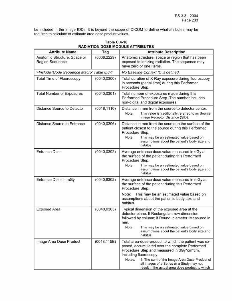
PS 3.3 - 2004 Page 233
be included in the Image IODs. It is beyond the scope of DICOM to define what attributes may be required to calculate or estimate area dose product values.
Table C.4-16 RADIATION DOSE MODULE ATTRIBUTES
Attribute Name Tag Attribute Description Anatomic Structure, Space or Region Sequence
(0008,2229) Anatomic structure, space or region that has been exposed to ionizing radiation. The sequence may have zero or one Items.
>Include ‘Code Sequence Macro’ Table 8.8-1 No Baseline Context ID is defined. Total Time of Fluoroscopy (0040,0300) Total duration of X-Ray exposure during fluoroscopy
in seconds (pedal time) during this Performed Procedure Step.
Total Number of Exposures (0040,0301) Total number of exposures made during this Performed Procedure Step. The number includes non-digital and digital exposures.
Distance Source to Detector (0018,1110) Distance in mm from the source to detector center. Note: This value is traditionally referred to as Source
Image Receptor Distance (SID).
Distance Source to Entrance (0040,0306) Distance in mm from the source to the surface of the patient closest to the source during this Performed Procedure Step.
Note: This may be an estimated value based on assumptions about the patient’s body size and habitus.
Entrance Dose (0040,0302) Average entrance dose value measured in dGy at the surface of the patient during this Performed Procedure Step.
Note: This may be an estimated value based on assumptions about the patient’s body size and habitus.
Entrance Dose in mGy (0040,8302) Average entrance dose value measured in mGy at the surface of the patient during this Performed Procedure Step. Note: This may be an estimated value based on assumptions about the patient’s body size and habitus.
Exposed Area (0040,0303) Typical dimension of the exposed area at the detector plane. If Rectangular: row dimension followed by column; if Round: diameter. Measured in mm.
Note: This may be an estimated value based on assumptions about the patient’s body size and habitus.
Image Area Dose Product (0018,115E) Total area-dose-product to which the patient was ex-posed, accumulated over the complete Performed Procedure Step and measured in dGy*cm*cm, including fluoroscopy.
Notes: 1. The sum of the Image Area Dose Product of all images of a Series or a Study may not result in the actual area dose product to which

PS 3.3 - 2004 Page 234
the patient was exposed. 2. This may be an estimated value based on
assumptions about the patient’s body size and habitus.
Comments on Radiation Dose (0040,0310) User-defined comments on any special conditions related to radiation dose encountered during this Performed Procedure Step.
Exposure Dose Sequence (0040,030E) Exposure Dose Sequence will contain Total Number of Exposures (0040, 0301) items plus an item for each fluoroscopy episode not already counted as an exposure.
>Radiation Mode (0018,115A) Specifies X-Ray radiation mode. Enumerated Values: CONTINUOUS PULSED
>KVp (0018,0060) Peak kilo voltage output of the x-ray generator used. An average in the case of fluoroscopy (continuous radiation mode).
>X-ray Tube Current in µA (0018,8151) X-ray Tube Current in µA. An average in the case of fluoroscopy (continuous radiation mode).
>Exposure Time (0018,1150) Time of x-ray exposure or fluoroscopy in msec. >Filter Type (0018,1160) Type of filter(s) inserted into the X-Ray beam (e.g.
wedges). See C.7.10 for Defined Terms. >Filter Material (0018,7050) The X-Ray absorbing material used in the filter. May
be multi-valued. See C.7.10 for Defined Terms.
Notes: 1. The Anatomic Region may be deduced from attribute values available within the Modality Worklist Management SOP Class, such as Reason for Service Request, Reasons for Requested Procedure, Scheduled Procedure Step Description and Scheduled Protocol Code Sequence.
2. The Image Area Dose Product should take into account collimator position and filters, and the value for the Exposed Area should also take into account collimator position. If the equipment does not provide the Entrance Dose, it may be calculated using Area Dose Product, Exposed Area, SID and an assumed body thickness.
3. The Distance Source to Detector (0018,1110) and Exposed Area (0040,0303) are only meaningful if they remain constant for all acquisitions during this Performed Procedure Step.
C.4.17 Billing and Material Management Codes The Attributes defined in Table C.4-17 provide a means to transmit billing and material management codes from a modality to an Information System. It is beyond the scope of this Standard to define all the required coding schemes and the relevant codes.
Table C.4-17 BILLING AND MATERIAL MANAGEMENT CODE MODULE ATTRIBUTES
Attribute name Tag Attribute Description Billing Procedure Step Sequence
(0040,0320) Contains billing codes for the Procedure Type performed within the Procedure Step. The sequence may have zero or more Items.
>Include ‘Code Sequence Macro’ Table 8.8-1 No Baseline Context ID is defined.

PS 3.3 - 2004 Page 235
Film Consumption Sequence (0040,0321) Information about the film consumption for this Per-formed Procedure Step. The sequence may have zero or more Items.
>Number of Films (2100,0170) Number of films actually printed. >Medium Type (2000,0030) Type(s) of medium on which images were printed.
For Defined Terms see Table C.13-1. >Film Size ID (2010,0050) Size(s) of film on which images were printed. For
Defined Terms see Table C.13-3. Billing Supplies and Devices Sequence
(0040,0324) Chemicals, supplies and devices for billing used in the Performed Procedure Step. The sequence may have one or more Items.
>Billing Item Sequence (0040,0296) Code values of chemicals, supplies or devices required for billing. The sequence may have zero or one Items.
>>Include ‘Code Sequence Macro’ Table 8.8-1 No Baseline Context ID is defined. >Quantity Sequence (0040,0293) Sequence containing the quantity of used chemicals
or devices. The sequence may have zero or one Items.
>>Quantity (0040,0294) Numerical quantity value. >>Measuring Units Sequence (0040,0295) Unit of measurement. The sequence may have zero
or one Items. >>>Include ‘Code Sequence Macro’ Table 8.8-1 Baseline Context ID is 82.
C.4.18 General Purpose Scheduled Procedure Step Relationship Module
Table C.4-18 GENERAL PURPOSE SCHEDULED PROCEDURE STEP RELATIONSHIP MODULE
ATTRIBUTES Attribute Name Tag Attribute Description
Patient's Name (0010,0010) Patient's full legal name. Patient ID (0010,0020) Primary hospital identification number or code for
the patient. Issuer of Patient ID (0010,0021) Identifier of the Assigning Authority that issued the
Patient ID. Patient's Birth Date (0010,0030) Date of birth of the named patient. Patient's Sex (0010,0040) Sex of the named Patient.
Enumerated Values: M = male F = female O = other
Referenced Request Sequence (0040,A370) The list of Requested Procedures the Procedure Step shall contribute to. One or more Items may be included in the sequence.

PS 3.3 - 2004 Page 236
>Study Instance UID (0020,000D) Unique identifier for the Study. >Referenced Study Sequence (0008,1110) Uniquely identifies the Detached Study
Management SOP Instance that represents the Requested Procedure. Zero or one Item may be included in this sequence.
>>Referenced SOP Class UID (0008,1150) Uniquely identifies the SOP Class. >>Referenced SOP Instance UID
(0008,1155) Uniquely identifies the SOP Instance.
>Accession Number (0008,0050) A departmental IS generated number that identifies the Imaging Service Request.
>Requested Procedure Code Sequence
(0032,1064) A sequence that conveys the Procedure Type of the Requested Procedure. Zero or one Item may be included in this sequence.
>>Include Code Sequence Macro Table 8.8-1 No Baseline Context ID is defined. >Placer Order Number / Imaging Service Request
(0040,2016) The order number assigned to the Imaging Service Request by the party placing the order.
>Filler Order Number / Imaging Service Request
(0040,2017) The order number assigned to the Imaging Service Request by the party filling the order.
>Requested Procedure ID (0040,1001) Identifier that identifies the Requested Procedure in the Imaging Service Request.
>Requested Procedure Description
(0032,1060) Institution-generated description or classification of the Requested Procedure.
>Reason for the Requested Procedure
(0040,1002) Reason for requesting this procedure.
> Reason for Requested Procedure Code Sequence
(0040,100A) Coded reason for requesting this procedure.
>>Include ‘Code Sequence Macro’ Table 8.8-1 No Baseline Context ID is defined. >Requested Procedure Comments
(0040,1400) User-defined comments on the Requested Procedure.
>Confidentiality Code (0040,1008) Confidentiality Constraints on the Requested Procedure by the party filling the order.
>Names of Intended Recipients of Results
(0040,1010) Names of the physicians, who are intended recipients of results.
>Imaging Service Request Comments
(0040,2400) User-defined comments on the Imaging Service Request.
>Requesting Physician (0032,1032) Physician who requested the Imaging Service Request.
>Requesting Service (0032,1033) Institutional department where the request initiated. >Issue Date of Imaging Service Request
(0040,2004) Date on which the Imaging Service Request was issued by the requester.
>Issue Time of Imaging Service Request
(0040,2005) Time at which the Imaging Service Request was issued by the requester.
>Referring Physician's Name (0008,0090) Patient's primary physician for this Imaging Service Request.
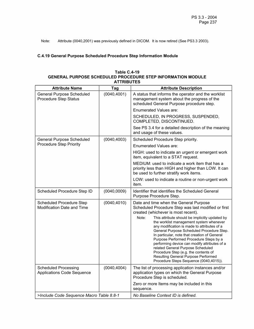
PS 3.3 - 2004 Page 237
Note: Attribute (0040,2001) was previously defined in DICOM. It is now retired (See PS3.3 2003).
C.4.19 General Purpose Scheduled Procedure Step Information Module
Table C.4-19 GENERAL PURPOSE SCHEDULED PROCEDURE STEP INFORMATION MODULE
ATTRIBUTES Attribute Name Tag Attribute Description
General Purpose Scheduled Procedure Step Status
(0040,4001) A status that informs the operator and the worklist management system about the progress of the scheduled General Purpose procedure step. Enumerated Values are: SCHEDULED, IN PROGRESS, SUSPENDED, COMPLETED, DISCONTINUED. See PS 3.4 for a detailed description of the meaning and usage of these values.
General Purpose Scheduled Procedure Step Priority
(0040,4003) Scheduled Procedure Step priority. Enumerated Values are: HIGH: used to indicate an urgent or emergent work item, equivalent to a STAT request. MEDIUM: used to indicate a work item that has a priority less than HIGH and higher than LOW. It can be used to further stratify work items. LOW: used to indicate a routine or non-urgent work item.
Scheduled Procedure Step ID (0040,0009) Identifier that identifies the Scheduled General Purpose Procedure Step.
Scheduled Procedure Step Modification Date and Time
(0040,4010) Date and time when the General Purpose Scheduled Procedure Step was last modified or first created (whichever is most recent).
Note: This attribute should be implicitly updated by the worklist management system whenever any modification is made to attributes of a General Purpose Scheduled Procedure Step. In particular, note that creation of General Purpose Performed Procedure Steps by a performing device can modify attributes of a related General Purpose Scheduled Procedure Step (e.g. the contents of Resulting General Purpose Performed Procedure Steps Sequence (0040,4015)).
Scheduled Processing Applications Code Sequence
(0040,4004) The list of processing application instances and/or application types on which the General Purpose Procedure Step is scheduled. Zero or more Items may be included in this sequence.
>Include Code Sequence Macro Table 8.8-1 No Baseline Context ID is defined.

PS 3.3 - 2004 Page 238
Scheduled Station Name Code Sequence
(0040,4025) Identifying name within the enterprise of the equipment for which the General Purpose Scheduled Procedure Step is scheduled. The name conveyed in the Code Value (0008,0100) may be the same as the AE Title, but does not have to be. Zero or more Items may be included in this sequence.
>Include Code Sequence Macro Table 8.8-1 No Baseline Context ID is defined. Scheduled Station Class Code Sequence
(0040,4026) Class of the equipment for which the General Purpose Scheduled Procedure Step is scheduled. Zero or more Items may be included in this sequence.
>Include Code Sequence Macro Table 8.8-1 No Baseline Context ID is defined. Scheduled Station Geographic Location Code Sequence
(0040,4027) Geographic location of the equipment for which the General Purpose Scheduled Procedure Step is scheduled. Zero or more Items may be included in this sequence.
>Include Code Sequence Macro Table 8.8-1 No Baseline Context ID is defined. Scheduled Human Performers Sequence
(0040,4034) The list of human performers that are scheduled to be involved or responsible for performing the Workitem in the General Purpose Scheduled Procedure Step. Zero or more Items may be included in this sequence.
>Human Performer Code Sequence
(0040,4009) Human performer that is involved or responsible for performing the Workitem. Only a single Item shall be permitted in this sequence.
>>Include Code Sequence Macro Table 8.8-1 No Baseline Context ID is defined. >Human Performer's Name (0040,4037) Name of the human performer. >Human Performer's Organization
(0040,4036) Organization to which the human performer is accountable for the activities in the Workitem.
Scheduled Procedure Step Start Date and Time
(0040,4005) Date and time on which the General Purpose Scheduled Procedure Step is scheduled to start.
Expected Completion Date and Time
(0040,4011) Date on which the Procedure Step is expected to be completed.
Scheduled Workitem Code Sequence
(0040,4018) A sequence that conveys the code for the Workitem.Only a single Item shall be permitted in this sequence.
>Include Code Sequence Macro Table 8.8-1 Baseline Context ID is CID 9231. Comments on the Scheduled Procedure Step
(0040,0400) User-defined comments on the Scheduled Procedure Step.
Referenced Performed Procedure Step Sequence
(0008,1111) List of any Modality or General Purpose Performed Procedure Steps, or other Study Components, that may be used to perform the procedure step.

PS 3.3 - 2004 Page 239
This sequence may contain references to performed procedure steps resulting from previous contributions to the performance of the procedure step (e.g. an image processing procedure step interrupted, and completed later). Zero or more Items may be included in this sequence.
>Referenced SOP Class UID (0008,1150) Uniquely identifies the SOP Class. >Referenced SOP Instance UID (0008,1155) Uniquely identifies the SOP Instance. Input Availability Flag (0040,4020) Flag that indicates the availability of Composite
SOP Instances in the Attribute “Input Information Sequence” (0040,4021) of the General Purpose Scheduled Procedure Step. Enumerated values are: PARTIAL COMPLETE The value PARTIAL denotes that the list of Composite SOP Instances may not yet be complete, and additional ones may be added at a later time. The value COMPLETE denotes that all Composite SOP Instances are available and listed.
Note: It may happen that the list of Composite SOP Instances is empty when the value of the Input Availability Flag is COMPLETE. In such a case a Workitem has been scheduled that does not require input information.
Input Information Sequence (0040,4021) List of Composite SOP Instances that forms the input information needed to perform the scheduled procedure step. See also Input Availability Flag (0040,4020). The same Composite SOP Instance shall not be included in both the Input Information Sequence (0040,4021) and the Relevant Information Sequence (0040,4022). Zero or more Items may be included in this sequence.
>Include 'SOP Instance Reference Macro' Table C.17-3 Relevant Information Sequence (0040,4022) List of Composite SOP Instances that refers to
relevant information that is considered pertinent for the performance of the scheduled procedure step. The same Composite SOP Instance shall not be included in both the Input Information Sequence (0040,4021) and the Relevant Information Sequence (0040,4022). Zero or more Items may be included in this sequence.
>Include 'SOP Instance Reference Macro' Table C.17-3 Study Instance UID (0020,000D) Unique Study identification that shall be used for the
created Composite SOP Instances resulting from this General Purpose Scheduled Procedure Step.
Note: In most cases this will be the same Study

PS 3.3 - 2004 Page 240
Instance UID as for the images in the Input Information Sequence (0040,4021).
Multiple Copies Flag (0040,4006) This flag indicates that multiple copies have to be made of a Composite SOP Instance that supports the notion of multiple copies. This includes the SR SOP Class. If set the Study Instance UIDs in the Referenced Request Sequence (0040,A370) shall be used for the created multiple copies. Enumerated Values: Y = Yes N = No
Resulting General Purpose Performed Procedure Steps Sequence
(0040,4015) List of all General Purpose Performed Procedure Steps that result from the performance of the procedure step. Zero or more Items may be included in this sequence.
Note: Initially this list will be empty. New entries will be added when General Purpose Performed Procedure Steps are created by performing devices that are related to this Scheduled Procedure Step. E.g, this sequence may contain the partial results in case a General Purpose Scheduled Procedure Step is discontinued.
>Referenced SOP Class UID (0008,1150) Uniquely identifies the SOP Class. >Referenced SOP Instance UID (0008,1155) Uniquely identifies the SOP Instance. Actual Human Performers Sequence
(0040,4035) The list of current human performers that are actually involved or responsible for performing the Workitem. Zero or more Items may be included in this sequence.
Note: Initially this list will be empty. A list of entries may be created at the status transition of the General Purpose Scheduled Procedure Step Status (0040,4001) to "IN PROGRESS"
>Human Performer Code Sequence
(0040,4009) Human performer that is involved or responsible for performing the Workitem. Only a single Item shall be permitted in this sequence.
>>Include Code Sequence Macro Table 8.8-1 No Baseline Context ID is defined. >Human Performer's Name (0040,4037) Name of the human performer. >Human Performer's Organization
(0040,4036) Organization to which the human performer is accountable for the activities in the Workitem.
C.4.20 General Purpose Performed Procedure Step Relationship Module Table C.4.20-1 specifies the Attributes used to reference other SOP Classes and other Information Entities of the DICOM real-world model as defined in PS 3.3 Section 7.3.1.11.
Table C.4.20-1

PS 3.3 - 2004 Page 241
GENERAL PURPOSE PERFORMED PROCEDURE STEP RELATIONSHIP MODULE ATTRIBUTES
Attribute Name Tag Attribute Description Patient's Name (0010,0010) Patient's full legal name. Patient ID (0010,0020) Primary hospital identification number or code for the
patient. Issuer of Patient ID (0010,0021) Identifier of the Assigning Authority that issued the
Patient ID. Patient's Birth Date (0010,0030) Date of birth of the named patient. Patient's Sex (0010,0040) Sex of the named Patient.
Enumerated Values: M = male F = female O = other
Referenced Request Sequence
(0040,A370) The list of Requested Procedures the Procedure Step shall contribute to. Zero or more Items may be included in the sequence.
>Study Instance UID (0020,000D) Unique identifier for the Study. >Referenced Study Sequence (0008,1110) Uniquely identifies the Study SOP Instance
associated with this Scheduled Procedure Step. Only a single Item shall be permitted in this sequence.
>>Referenced SOP Class UID (0008,1150) Uniquely identifies the SOP Class. >>Referenced SOP Instance UID
(0008,1155) Uniquely identifies the SOP Instance.
>Accession Number (0008,0050) A departmental IS generated number that identifies the order for the Study.
>Requested Procedure Code Sequence
(0032,1064) A sequence that conveys the Procedure Type of the Requested Procedure. Zero or one Item may be included in this sequence.
>>Include Code Sequence Macro Table 8.8-1 No Baseline Context ID is defined. >Placer Order Number/Imaging Service Request
(0040,2016) The order number assigned to the Imaging Service Request by the party placing the order.
>Filler Order Number/Imaging Service Request
(0040,2017) The order number assigned to the Imaging Service Request by the party filling the order.
>Requested Procedure ID (0040,1001) Identifier of the related Requested Procedure. >Requested Procedure Description
(0032,1060) Institution-generated administrative description or classification of Requested Procedure.
Referenced General Purpose Scheduled Procedure Step Sequence
(0040,4016) Uniquely identifies the General Purpose Scheduled Procedure Step SOP Instance associated with this General Purpose Performed Procedure Step. Zero or more Items may be included in this sequence.

PS 3.3 - 2004 Page 242
>Referenced SOP Class UID (0008,1150) Uniquely identifies the SOP Class. >Referenced SOP Instance UID
(0008,1155) Uniquely identifies the SOP Instance.
>Referenced General Purpose Scheduled Procedure Step Transaction UID
(0040,4023) Transaction UID (0008,1195) used in the N-ACTION transaction that requested the transition to the IN PROGRESS state for the referenced General Purpose Scheduled Procedure Step.
C.4.21 General Purpose Performed Procedure Step Information Module
Table C.4.21-1 GENERAL PURPOSE PERFORMED PROCEDURE STEP INFORMATION MODULE
ATTRIBUTES Attribute Name Tag Attribute Description
Actual Human Performers Sequence
(0040,4035) The list of human performers that were actually involved in or responsible for performing this General Purpose Performed Procedure Step. Zero or more Items may be included in this sequence.
>Human Performer Code Sequence
(0040,4009) Human performer that is actually involved or responsible for performing the General Purpose Performed Procedure Step. Only a single Item shall be permitted in this sequence.
>>Include Code Sequence Macro Table 8.8-1 No Baseline Context ID is defined. >Human Performer's Name (0040,4037) Name of the human performer. >Human Performer's Organization
(0040,4036) Organization to which the human performer is accountable for the activities in the General Purpose Performed Procedure Step.
Performed Station Name Code Sequence
(0040,4028) Name within the enterprise of the equipment that created the General Purpose Performed Procedure Step. This name may be the same as the AE Title, but does not have to be. Zero or one Item may be included in this sequence.
>Include Code Sequence Macro Table 8.8-1 No Baseline Context ID is defined. Performed Station Class Code Sequence
(0040,4029) Class of the equipment that created the General Purpose Performed Procedure Step. Zero or one Item may be included in this sequence.
>Include Code Sequence Macro Table 8.8-1 No Baseline Context ID is defined. Performed Station Geographic Location Code Sequence
(0040,4030) Geographic location of the equipment that created General Purpose Performed Procedure Step. Zero or one Item may be included in this sequence.
>Include Code Sequence Macro Table 8.8-1 No Baseline Context ID is defined. Performed Processing Applications Code Sequence
(0040,4007) The list of processing application instances and/or application types on which the General Purpose Performed Procedure Step is executed. Zero or more Items may be included in this sequence.

PS 3.3 - 2004 Page 243
>Include Code Sequence Macro Table 8.8-1 No Baseline Context ID is defined. Performed Procedure Step Start Date
(0040,0244) Date on which the General Purpose Performed Procedure Step started.
Performed Procedure Step Start Time
(0040,0245) Time at which the General Purpose Performed Procedure Step started.
Performed Procedure Step ID (0040,0253) User or equipment generated identifier of that part of a Procedure that has been carried out within this procedure step.
Performed Procedure Step End Date
(0040,0250) Date on which the General Purpose Performed Procedure Step ended.
Performed Procedure Step End Time
(0040,0251) Time at which the General Purpose Performed Procedure Step ended.
General Purpose Performed Procedure Step Status
(0040,4002) Contains the state of the Performed Procedure Step. Enumerated Values: IN PROGRESS = Started but not complete DISCONTINUED = Canceled or unsuccessfully terminated COMPLETED = Successfully completed
Performed Procedure Step Description
(0040,0254) Institution-generated description or classification of the Procedure Step that was performed.
Comments on the Performed Procedure Step
(0040,0280) User-defined comments on the Performed Procedure Step. This attribute shall not be used as a substitute for the code meaning in the Performed Workitem Code Sequence (0040,4019).
Performed Workitem Code Sequence
(0040,4019) A sequence that conveys the (single) type of procedure performed. Only a single Item shall be permitted in this sequence.
>Include Code Sequence Macro Table 8.8-1 Baseline Context ID is CID 9231.
C.4.22 General Purpose Results Table C.4.22-1 specifies attributes that describe the creation of results during the performance of the General Purpose Procedure Step and that provide references to the Results and Structured Reporting SOP Instances associated with this General Purpose Performed Procedure Step.
Table C.4.22-1 GENERAL PURPOSE RESULTS MODULE ATTRIBUTES
Attribute Name Tag Attribute Description Output Information Sequence (0040,4033) A Sequence that provides reference to one or more
Composite SOP instances, that identify the Structured Reports or other results created. Zero or more Items may be included in this sequence.
>Include 'SOP Instance Reference Macro' Table C.17-3 Requested Subsequent Workitem Code Sequence
(0040,4031) A Sequence that provides suggested next Workitems, based on the produced results.
Note: This Attribute may also be used in case a step has been done incorrectly and should be redone.

PS 3.3 - 2004 Page 244
Zero or more Items may be included in this sequence >Include Code Sequence Macro Table 8.8-1 Baseline Context ID is CID 9231. Non-DICOM Output Code Sequence
(0040,4032) A Sequence that describes any non-DICOM output produced as results. Zero or more Items may be included in this sequence.
>Include Code Sequence Macro Table 8.8-1 Baseline Context ID is CID 9232.
C.4.23 Instance Availability Notification Module Table C.4.23-1 specifies the Attributes used to describe which Instances are available and their relationships.
Table C.4.23-1 INSTANCE AVAILABILITY NOTIFICATION MODULE ATTRIBUTES
Attribute Name Tag Attribute Description Referenced Performed Procedure Step Sequence
(0008,1111) Uniquely identifies the Performed Procedure Step SOP Instance to which this availability notification instance is related, if any. The Sequence shall have zero or one Item.
Notes: 1. This may refer to a different PPS than that encoded in the composite instances themselves.
2. It is typically used for notification about instances created as a consequence of some scheduled activity.
>Referenced SOP Class UID (0008,1150) Uniquely identifies the referenced SOP Class of the Performed Procedure Step.
>Referenced SOP Instance UID
(0008,1155) Uniquely identifies the referenced SOP Instance of the Performed Procedure Step.
>Performed Workitem Code Sequence
(0040,4019) A sequence that conveys the (single) type of procedure performed. Only a single Item shall be permitted in this sequence.
>>Include Code Sequence Macro Table 8.8-1 Baseline Context ID is CID 9231. Study Instance UID (0020,000D) Unique identifier for the Study of which all the
Instances referenced in this notification are part. Referenced Series Sequence (0008,1115) Sequence of Items where each Item includes
references to Instances within the same Series. One or more Items shall be included in this Sequence.
>Series Instance UID (0020,000E) Unique identifier of the Series of which all the Instances referenced in this Item are part.
>Referenced SOP Sequence (0008,1199) Sequence of Items where each Item includes a reference to a single Instance within this Series. One or more Items shall be included in this Sequence.
>>Referenced SOP Class UID (0008,1150) Uniquely identifies the referenced SOP Class. >>Reference SOP Instance UID
(0008,1155) Uniquely identifies the referenced SOP Instance.

PS 3.3 - 2004 Page 245
>>Instance Availability (0008,0056) The availability of the referenced Instance. See Section C.4.23.1.1
>>Retrieve AE Title (0008,0054) Title of the DICOM Application Entity from which the referenced Instance may or may not be retrievable, i.e. the scope for which Instance Availability (0008,0056) applies. See Section C.4.23.1.1.
>>Storage Media File-Set ID (0088,0130) The user or implementation specific human readable identifier that identifies the offline storage media on which the instance resides.
>>Storage Media File-Set UID (0088,0140) Uniquely identifies the offline storage media on which the instance resides.
C.4.23.1 Instance Availability Notification Module Attribute Definitions C.4.23.1.1 Instance Availability The Enumerated Values for Instance Availability (0008,0056) are:
— “ONLINE” means the instances are immediately available from the Retrieve AE Title (0008,0054), and if a C-MOVE were to be requested, it would succeed in a reasonably short time
— “NEARLINE” means the instances need to be retrieved from relatively slow media such as optical disk or tape, and if a C-MOVE were to be requested from the Retrieve AE Title (0008,0054), it would succeed, but may take a considerable time
— “OFFLINE” means that a manual intervention is needed before the instances may be retrieved, and if a C-MOVE were to be requested from the Retrieve AE Title (0008,0054), it would fail (e.g., by timeout) without such manual intervention.
— “UNAVAILABLE” means the instances cannot be retrieved from the Retrieve AE Title (0008,0054), and if a C-MOVE were to be requested, it would fail. Note that SOP Instances that are unavailable from this AE may be available from other AEs, or may have an alternate representation that is available from this AE.
C.5 RESULTS MODULES
The following Sections specify Modules relevant to a real world diagnostic imaging results performed on a patient.

PS 3.3 - 2004 Page 246
C.5.1 Results Relationship Module Table C.5-1 defines the Attributes that reference SOP Instances Subordinate or Superior to this SOP Class in the Naming Hierarchy.
Table C.5-1 RESULTS RELATIONSHIP MODULE ATTRIBUTES
Attribute Name Tag Attribute Description Referenced Study Sequence (0008,1110) Uniquely identifies the Study SOP Instances
associated with the Results SOP Instance. >Referenced SOP Class UID (0008,1150) Uniquely identifies the referenced SOP Class. >Referenced SOP Instance UID (0008,1155) Uniquely identifies the referenced SOP Instance. Referenced Interpretation Sequence (4008,0050) Uniquely identifies the report SOP Instances and
amendment SOP Instances that comprise the results SOP Instance. Zero or more Items may be included in this Sequence.
>Referenced SOP Class UID (0008,1150) Uniquely identifies the referenced SOP Class. >Referenced SOP Instance UID (0008,1155) Uniquely identifies the referenced SOP Instance.
C.5.2 Results Identification Module Table C.5-2 defines the Attributes relevant to identifying results.
Table C.5-2 RESULTS IDENTIFICATION MODULE ATTRIBUTES
Attribute Name Tag Attribute Description Results ID (4008,0040) Healthcare provider generated number used to
reference the results Results ID Issuer (4008,0042) Name of healthcare provider which issued the
results ID
C.5.3 Results Impressions Module Table C.5-3 defines the Attributes relevant to the result's impressions.
Table C.5-3 RESULTS IMPRESSION MODULE ATTRIBUTES
Attribute Name Tag Attribute Description Impressions (4008,0300) Short impressions summarizing the full results Results Comments (4008,4000) User-defined comments about the results
C.6 INTERPRETATION MODULES
The following Sections specify Modules relevant to a real world results interpretation.

PS 3.3 - 2004 Page 247
C.6.1 Interpretation Relationship Module Table C.6-1 defines the Attributes that reference SOP Instances Subordinate or Superior to this SOP Class in the Naming Hierarchy.
Table C.6-1 INTERPRETATION RELATIONSHIP MODULE ATTRIBUTES
Attribute Name Tag Attribute Description Referenced Results Sequence (0008,1100) Uniquely identifies the results SOP Instances for
which the interpretation SOP Instance applies. Only a single Item shall be permitted in this Sequence.
>Referenced SOP Class UID (0008,1150) Uniquely identifies the referenced SOP Class. >Referenced SOP Instance ID (0008,1155) Uniquely identifies the referenced SOP Instance.
C.6.2 Interpretation Identification Module Table C.6-2 defines the Attributes relevant to identifying an interpretation.
Table C.6-2 INTERPRETATION IDENTIFICATION MODULE ATTRIBUTES
Attribute Name Tag Attribute Description Interpretation ID (4008,0200) Healthcare provider generated number used to
reference the interpretation Interpretation ID Issuer (4008,0202) Name of healthcare provider which issued the
interpretation ID
C.6.3 Interpretation State Module Table C.6-3 defines the Attributes relevant to the state of an interpretation.
Table C.6-3 INTERPRETATION STATE MODULE ATTRIBUTES
Attribute Name Tag Attribute Description Interpretation Type ID (4008,0210) The type of interpretation. Defined Terms:
REPORT = Report AMENDMENT = Amendment
Interpretation Status ID (4008,0212) An Enumerated Value element used to track production status of the interpretation. Enumerated Values: CREATED = Interpretation Created RECORDED = Interpretation captured in a format external to the information system which handles reports. TRANSCRIBED = Interpretation converted into or entered in the internal format of the information system which handles reports. APPROVED = Interpretation Approved

PS 3.3 - 2004 Page 248
C.6.4 Interpretation Recording Module Table C.6-4 defines the Attributes relevant to the recording of an interpretation.
Table C.6-4 INTERPRETATION RECORDING MODULE ATTRIBUTES
Attribute Name Tag Attribute Description Interpretation Recorded Date (4008,0100) Date interpretation was dictated or entered Interpretation Recorded Time (4008,0101) Time interpretation was dictated or entered Interpretation Recorder (4008,0102) Name of the person who recorded the
interpretation Reference to Recorded Sound (4008,0103) A reference used to identify or locate the sound
recording of the interpretation
C.6.5 Interpretation Transcription Module Table C.6-5 defines the Attributes relevant to the transcription of an interpretation recording.
Table C.6-5 INTERPRETATION TRANSCRIPTION MODULE ATTRIBUTES
Attribute Name Tag Attribute Description Interpretation Transcription Date (4008,0108) Date interpretation was transcribed. Interpretation Transcription Time (4008,0109) Time interpretation was transcribed. Interpretation Transcriber (4008,010A) Name of person who transcribed the
interpretation. Interpretation Text (4008,010B) Text of the interpretation. Interpretation Author (4008,010C) Name of author of interpretation.
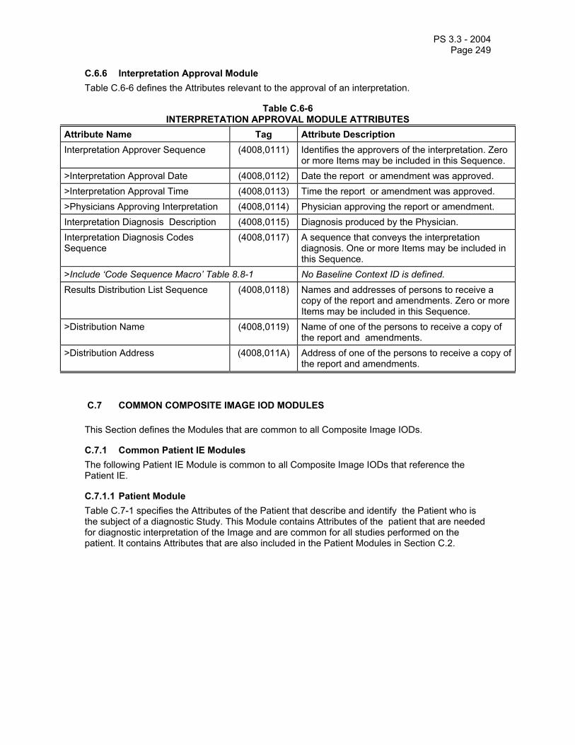
PS 3.3 - 2004 Page 249
C.6.6 Interpretation Approval Module Table C.6-6 defines the Attributes relevant to the approval of an interpretation.
Table C.6-6 INTERPRETATION APPROVAL MODULE ATTRIBUTES
Attribute Name Tag Attribute Description Interpretation Approver Sequence (4008,0111) Identifies the approvers of the interpretation. Zero
or more Items may be included in this Sequence. >Interpretation Approval Date (4008,0112) Date the report or amendment was approved. >Interpretation Approval Time (4008,0113) Time the report or amendment was approved. >Physicians Approving Interpretation (4008,0114) Physician approving the report or amendment. Interpretation Diagnosis Description (4008,0115) Diagnosis produced by the Physician. Interpretation Diagnosis Codes Sequence
(4008,0117) A sequence that conveys the interpretation diagnosis. One or more Items may be included in this Sequence.
>Include ‘Code Sequence Macro’ Table 8.8-1 No Baseline Context ID is defined. Results Distribution List Sequence (4008,0118) Names and addresses of persons to receive a
copy of the report and amendments. Zero or more Items may be included in this Sequence.
>Distribution Name (4008,0119) Name of one of the persons to receive a copy of the report and amendments.
>Distribution Address (4008,011A) Address of one of the persons to receive a copy of the report and amendments.
C.7 COMMON COMPOSITE IMAGE IOD MODULES
This Section defines the Modules that are common to all Composite Image IODs.
C.7.1 Common Patient IE Modules The following Patient IE Module is common to all Composite Image IODs that reference the Patient IE.
C.7.1.1 Patient Module Table C.7-1 specifies the Attributes of the Patient that describe and identify the Patient who is the subject of a diagnostic Study. This Module contains Attributes of the patient that are needed for diagnostic interpretation of the Image and are common for all studies performed on the patient. It contains Attributes that are also included in the Patient Modules in Section C.2.

PS 3.3 - 2004 Page 250
Table C.7-1 PATIENT MODULE ATTRIBUTES
Attribute Name Tag Type Attribute Description Patient's Name (0010,0010) 2 Patient's full name. Patient ID (0010,0020) 2 Primary hospital identification number or
code for the patient. Issuer of Patient ID (0010,0021) 3 Identifier of the Assigning Authority that
issued the Patient ID. Patient's Birth Date (0010,0030) 2 Birth date of the patient. Patient's Sex (0010,0040) 2 Sex of the named patient.
Enumerated Values: M = male F = female O = other
Referenced Patient Sequence (0008,1120) 3 A sequence that provides reference to a Patient SOP Class/Instance pair. Only a single Item shall be permitted in this Sequence.
>Referenced SOP Class UID (0008,1150) 1C Uniquely identifies the referenced SOP Class. Required if Referenced Patient Sequence (0008,1120) is sent.
>Referenced SOP Instance UID (0008,1155) 1C Uniquely identifies the referenced SOP Instance. Required if Referenced Patient Sequence (0008,1120) is sent.
Patient's Birth Time (0010,0032) 3 Birth time of the Patient. Other Patient IDs (0010,1000) 3 Other identification numbers or codes
used to identify the patient. Other Patient Names (0010,1001) 3 Other names used to identify the patient. Ethnic Group (0010,2160) 3 Ethnic group or race of the patient. Patient Comments (0010,4000) 3 User-defined additional information about
the patient.
C.7.1.2 Specimen Identification Module Table C.7-2a specifies the Attributes that identify a Specimen.
Table C.7-2a SPECIMEN IDENTIFICATION MODULE ATTRIBUTES
Attribute Name Tag Type Attribute Description Specimen Accession Number (0040,050A) 1 A departmental Information System
identifier that identifies the Accession. See Section C.7.1.2.1.1 for further explanation.
Specimen Sequence (0040,0550) 2 Detailed description of one or more specimens. Zero or more Items may be included in this Sequence.
>Specimen Identifier (0040,0551) 2C A departmental information system identifier for the Specimen. See Section C.7.1.2.1.2 for further explanation.

PS 3.3 - 2004 Page 251
Required if a sequence item is present. >Specimen Type Code Sequence (0040,059A) 2C Specimen Type. Only a single Item shall be
permitted in this Sequence. Required if a sequence item is present and Specimen Identifier (0040,0551) is sent.
>>Include ‘Code Sequence Macro’ Table 8.8-1 No Baseline Context IDs are defined >Slide Identifier (0040,06FA) 2C Identifier of the Slide.
Required if a sequence item is present and the Specimen is a Slide.
C.7.1.2.1 Specimen Module Attributes C.7.1.2.1.1 Specimen Accession Number Specimen Accession Number (0040,06CA) is the primary identifier of the Specimen.
Note: Specimen Accession Number (0040,050A) identifies tissue or fluid obtained from a Patient in a Specimen-harvest procedure. This Attribute was created to differentiate Accession Numbers, as used in Anatomic Pathology to identify specimens, from other uses of the term “Accession Number” in Information Systems. The Specimen Accession Number (0040,050A) is typically unique within the scope of the institution in which the Accession is performed. An Accession may contain multiple Specimens. Typically, an Accession contains the Specimens obtained in one Specimen-harvest procedure and submitted by one Requesting Physician. However, multiple Specimen-harvest procedures may be involved.
C.7.1.2.1.2 Specimen Identifier Specimen Identifier (0040,050A) may be used to convey a slide number, a block number, or other secondary identifier of the Specimen.
Note: The Specimen Identifier (0040,0551) is typically unique within the scope of the institution in which the related Accession is performed. However, a value of Specimen Identifier (0040,0551) does not always exist. For example, it is common practice in some Anatomic Pathology departments to use a Specimen Identifier (0040,0551) to identify specimen-containers or blocks only if multiple containers or blocks are submitted for a single Accession. Therefore, Specimen Identifier (0040,0551) is modeled as a Type 2 Attribute.
C.7.1.3 Clinical Trial Subject Module Table C.7-2b contains attributes that identify a Patient as a clinical trial Subject.
Table C.7-2b CLINICAL TRIAL SUBJECT MODULE ATTRIBUTES
Attribute Name Tag Type Attribute Description Clinical Trial Sponsor Name (0012,0010) 1 The name of the clinical trial sponsor. See
C.7.1.3.1.1. Clinical Trial Protocol ID (0012,0020) 1 Identifier for the noted protocol. See
C.7.1.3.1.2. Clinical Trial Protocol Name (0012,0021) 2 The name of the clinical trial protocol. See
C.7.1.3.1.3. Clinical Trial Site ID (0012,0030) 2 The identifier of the site responsible for
submitting clinical trial data. See C.7.1.3.1.4.
Clinical Trial Site Name (0012,0031) 2 Name of the site responsible for submitting

PS 3.3 - 2004 Page 252
clinical trial data. See C.7.1.3.1.5 Clinical Trial Subject ID (0012,0040) 1C The assigned identifier for the clinical trial
subject. See C.7.1.3.1.6. Shall be present if Clinical Trial Subject Reading ID (0012,0042) is absent. May be present otherwise.
Clinical Trial Subject Reading ID (0012,0042) 1C Identifies the subject for blinded evaluations. Shall be present if Clinical Trial Subject ID (0012,0040) is absent. May be present otherwise. See C.7.1.3.1.7.
C.7.1.3.1 Clinical Trial Subject Attribute Descriptions Identification of subjects in clinical trials generally requires a combination of the following four attributes:
1. Clinical Trial Sponsor Name (0012,0010), 2. Clinical Trial Protocol ID (0012,0020), 3. Clinical Trial Subject ID (0012,0040) (or Clinical Trial Subject Reading ID
(0012,0042) for blinded evaluations), and 4. Clinical Trial Site ID (0012,0030).
For trials in which subject identifiers are unique within the scope of the Clinical Trial Protocol (e.g., if subject identifiers are centrally assigned or contain the site identifier) the Clinical Trial Site ID (0012,0030) is not required to identify subjects.
C.7.1.3.1.1 Clinical Trial Sponsor Name The Clinical Trial Sponsor Name (0012,0010) identifies the entity responsible for conducting the clinical trial and for defining the Clinical Trial Protocol ID (0012,0020).
C.7.1.3.1.2 Clinical Trial Protocol ID The Clinical Trial Protocol ID (0012,0020) is the number or character sequence used by the Clinical Trial Sponsor to uniquely identify the investigational protocol in which the subject has been enrolled.
C.7.1.3.1.3 Clinical Trial Protocol Name The Clinical Trial Protocol Name (0012,0021) contains the title of the investigational protocol in which the subject has been enrolled.
Note: It is recommended that the phase of the clinical trial be noted in the Clinical Trial Protocol Name, if applicable.
C.7.1.3.1.4 Clinical Trial Site ID The Clinical Trial Site ID (0012,0030) is the identification number or character string (issued by the entity identified by the Clinical Trial Sponsor Name (0012,0010)) used to identify the site responsible for submitting clinical trial data.
C.7.1.3.1.5 Clinical Trial Site Name The Clinical Trial Site Name (0012,0031) is a character string used to identify the site responsible for submitting clinical trial data.

PS 3.3 - 2004 Page 253
C.7.1.3.1.6 Clinical Trial Subject ID The Clinical Trial Subject ID (0012,0040) identifies the subject within the investigational protocol specified by Clinical Trial Protocol ID (0012,0020).
C.7.1.3.1.7 Clinical Trial Subject Reading ID The Clinical Trial Subject Reading ID (0012,0042) identifies the subject in the context of blinded evaluations.
C.7.2 Common Study IE Modules The following Study IE Modules are common to all Composite Image IODs that reference the Study IE. These Modules contain Attributes of the patient and study that are needed for diagnostic interpretation of the image. They contain Attributes that are also in the Patient Modules in Section C.2 and Study Modules in Section C.4.
C.7.2.1 General Study Module Table C.7-3 specifies the Attributes that describe and identify the Study performed upon the Patient.
Table C.7-3 GENERAL STUDY MODULE ATTRIBUTES
Attribute Name Tag Type Attribute Description Study Instance UID (0020,000D) 1 Unique identifier for the Study. Study Date (0008,0020) 2 Date the Study started. Study Time (0008,0030) 2 Time the Study started. Referring Physician's Name (0008,0090) 2 Name of the patient's referring physician Referring Physician Identification Sequence
(0008,0096) 3 Identification of the patient's referring physician. Only a single item shall be permitted in this sequence.
>Include ‘Person Identification Macro’ Table 10-1 Study ID (0020,0010) 2 User or equipment generated Study
identifier. Accession Number (0008,0050) 2 A RIS generated number that identifies the
order for the Study. Study Description (0008,1030) 3 Institution-generated description or
classification of the Study (component) performed.
Physician(s) of Record (0008,1048) 3 Names of the physician(s) who are responsible for overall patient care at time of Study (see Section C.7.3.1 for Performing Physician)
Physician(s) of Record Identification Sequence
(0008,1049) 3 Identification of the physician(s) who are responsible for overall patient care at time of Study. One or more items shall be included in this sequence. If more than one Item, the number and order shall correspond to the value of Physician(s) of Record (0008,1048), if present.
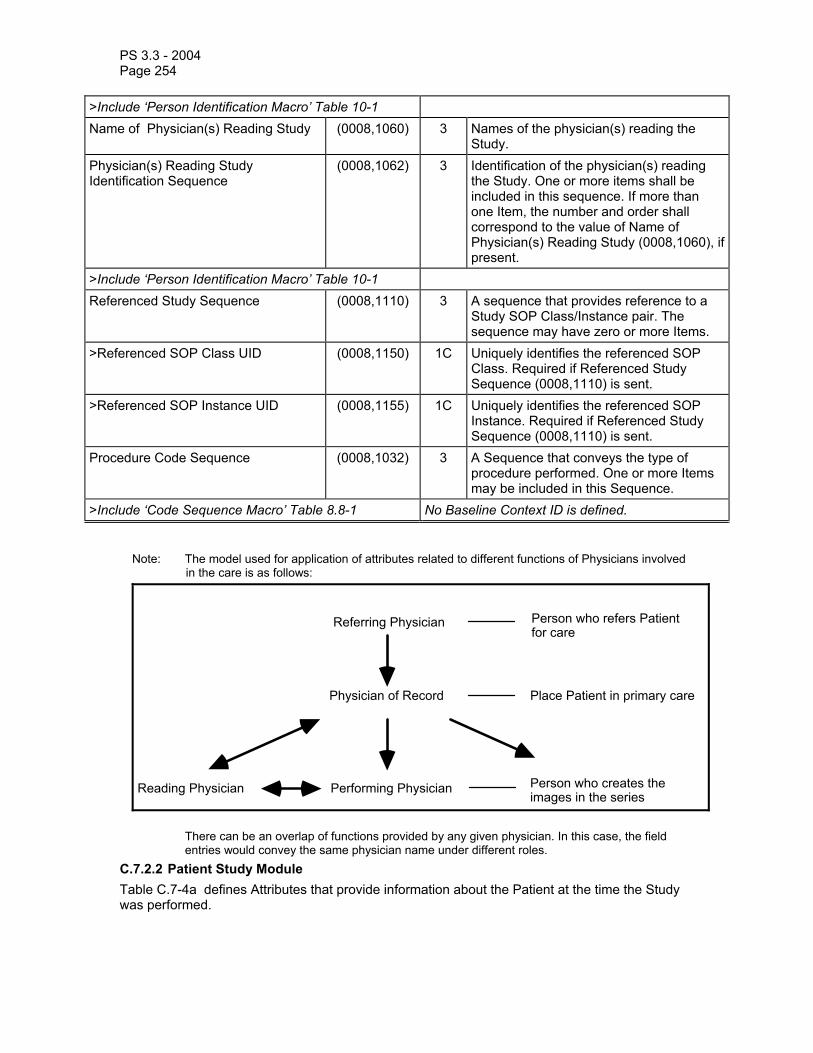
PS 3.3 - 2004 Page 254
>Include ‘Person Identification Macro’ Table 10-1 Name of Physician(s) Reading Study (0008,1060) 3 Names of the physician(s) reading the
Study. Physician(s) Reading Study Identification Sequence
(0008,1062) 3 Identification of the physician(s) reading the Study. One or more items shall be included in this sequence. If more than one Item, the number and order shall correspond to the value of Name of Physician(s) Reading Study (0008,1060), if present.
>Include ‘Person Identification Macro’ Table 10-1 Referenced Study Sequence (0008,1110) 3 A sequence that provides reference to a
Study SOP Class/Instance pair. The sequence may have zero or more Items.
>Referenced SOP Class UID (0008,1150) 1C Uniquely identifies the referenced SOP Class. Required if Referenced Study Sequence (0008,1110) is sent.
>Referenced SOP Instance UID (0008,1155) 1C Uniquely identifies the referenced SOP Instance. Required if Referenced Study Sequence (0008,1110) is sent.
Procedure Code Sequence (0008,1032) 3 A Sequence that conveys the type of procedure performed. One or more Items may be included in this Sequence.
>Include ‘Code Sequence Macro’ Table 8.8-1 No Baseline Context ID is defined.
Note: The model used for application of attributes related to different functions of Physicians involved in the care is as follows:
Referring Physician
Physician of Record
Performing PhysicianReading Physician
Person who refers Patient for care
Place Patient in primary care
Person who creates the images in the series
There can be an overlap of functions provided by any given physician. In this case, the field
entries would convey the same physician name under different roles. C.7.2.2 Patient Study Module Table C.7-4a defines Attributes that provide information about the Patient at the time the Study was performed.

PS 3.3 - 2004 Page 255
Table C.7-4a PATIENT STUDY MODULE ATTRIBUTES
Attribute Name Tag Type Attribute Description Admitting Diagnoses Description (0008,1080) 3 Description of the admitting diagnosis
(diagnoses) Admitting Diagnoses Code Sequence (0008,1084) 3 A sequence that conveys the admitting
diagnosis (diagnoses). One or more Items may be included in this Sequence.
>Include ‘Code Sequence Macro’ Table 8.8-1 No Baseline Context ID is defined. Patient's Age (0010,1010) 3 Age of the Patient. Patient's Size (0010,1020) 3 Length or size of the Patient, in meters. Patient's Weight (0010,1030) 3 Weight of the Patient, in kilograms. Occupation (0010,2180) 3 Occupation of the Patient. Additional Patient’s History (0010,21B0) 3 Additional information about the Patient's
medical history.
C.7.2.3 Clinical Trial Study Module Table C.7-4b contains attributes that identify a Study in the context of a clinical trial.
Table C.7-4b CLINICAL TRIAL STUDY MODULE ATTRIBUTES
Attribute Name Tag Type Attribute Description Clinical Trial Time Point ID (0012,0050) 2 An identifier specifying the one or more studies
that are grouped together as a clinical time point or submission in a clinical trial. See C.7.2.3.1.1.
Clinical Trial Time Point Description
(0012,0051) 3 A description of a set of one or more studies that are grouped together to represent a clinical time point or submission in a clinical trial. See C.7.2.3.1.1.
C.7.2.3.1 Clinical Trial Study Attribute Descriptions C.7.2.3.1.1 Clinical Trial Time Point The Clinical Trial Time Point ID (0012,0050) attribute identifies an imaging study within the context of an investigational protocol. This attribute is used to define a set of studies that are grouped together as a clinical time point or data submission in a clinical trial. The Clinical Trial Time Point Description (0012,0051) attribute can be used to give a description of the Clinical Trial Time Point to which the set of studies belongs.
C.7.3 Common Series IE Modules The following Series IE Modules are common to all Composite Image IODs that reference the Series IE.
C.7.3.1 General Series Module Table C.7-5a specifies the Attributes that identify and describe general information about the Series within a Study.

PS 3.3 - 2004 Page 256
Table C.7-5a GENERAL SERIES MODULE ATTRIBUTES
Attribute Name Tag Type Attribute Description Modality (0008,0060) 1 Type of equipment that originally acquired
the data used to create the images in this Series. See C.7.3.1.1.1 for Defined Terms.
Series Instance UID (0020,000E) 1 Unique identifier of the Series. Series Number (0020,0011) 2 A number that identifies this Series. Laterality (0020,0060) 2C Laterality of (paired) body part examined.
Required if the body part examined is a paired structure and Image Laterality (0020,0062) or Frame Laterality (0020,9072) are not sent. Enumerated Values: R = right L = left
Note: Some IODs support Image Laterality (0020,0062) at the Image level or Frame Laterality(0020,9072) at the Frame level in the Frame Anatomy functional group macro, which can provide a more comprehensive mechanism for specifying the laterality of the body part(s) being examined.
Series Date (0008,0021) 3 Date the Series started. Series Time (0008,0031) 3 Time the Series started. Performing Physicians’ Name (0008,1050) 3 Name of the physician(s) administering the
Series. Performing Physician Identification Sequence
(0008,1052) 3 Identification of the physician(s) administering the Series. One or more items shall be included in this sequence. If more than one Item, the number and order shall correspond to the value of Performing Physicians’ Name (0008,1050), if present.
>Include ‘Person Identification Macro’ Table 10-1 Protocol Name (0018,1030) 3 User-defined description of the conditions
under which the Series was performed. Note: This attribute conveys series-specific
protocol identification and may or may not be identical to the one presented in the Performed Protocol Code Sequence (0040,0260).
Series Description (0008,103E) 3 User provided description of the Series Operators' Name (0008,1070) 3 Name(s) of the operator(s) supporting the
Series. Operator Identification Sequence (0008,1072) 3 Identification of the operator(s) supporting
the Series. One or more items shall be included in this sequence. If more than one Item, the number and order shall correspond to the value of Operators’ Name

PS 3.3 - 2004 Page 257
(0008,1070), if present. >Include ‘Person Identification Macro’ Table 10-1 Referenced Performed Procedure Step Sequence
(0008,1111) 3 Uniquely identifies the Performed Procedure Step SOP Instance to which the Series is related (e.g. a Modality or General-Purpose Performed Procedure Step SOP Instance or Study Component SOP Instance). The Sequence shall have zero or one Item.
>Referenced SOP Class UID (0008,1150) 1C Uniquely identifies the referenced SOP Class. Required if Referenced Performed Procedure Step Sequence (0008,1111) is sent.
>Referenced SOP Instance UID (0008,1155) 1C Uniquely identifies the referenced SOP Instance. Required if Referenced Performed Procedure Step Sequence (0008,1111) is sent.
Related Series Sequence (0008,1250) 3 Identification of Series significantly related to this Series. Zero or more Items may be present.
Notes: 1. For example, for a combined CT and PET acquisition, the CT images and PET images would be in separate series that could cross-reference each other with multiple purpose of reference codes meaning same anatomy, simultaneously acquired and same indication.
2. The related series may have different Frames of Reference and hence require some sort of registration before spatial coordinates can be directly compared.
3. This attribute is not intended for conveying localizer reference information, for which Referenced Image Sequence (0008,1140) should be used.
>Study Instance UID (0020,000D) 1 Instance UID of Study to which the related Series belongs
>Series Instance UID (0020,000E) 1 Instance UID of Related Series >Purpose of Reference Code Sequence
(0040,A170) 2 Describes the purpose for which the reference is made. Zero or more Items may be present. When absent, implies that the reason for the reference is unknown.
>>Include Code Sequence Macro Table 8.8-1 DCID 7210 Body Part Examined (0018,0015) 3 Text description of the part of the body
examined. Defined Terms: SKULL, CSPINE, TSPINE, LSPINE,

PS 3.3 - 2004 Page 258
SSPINE, COCCYX, CHEST, CLAVICLE, BREAST, ABDOMEN, PELVIS, HIP, SHOULDER, ELBOW, KNEE, ANKLE, HAND, FOOT, EXTREMITY, HEAD, HEART, NECK, LEG, ARM, JAW
Note: Some IODs support the Anatomic Region Sequence (0008,2218), which can provide a more comprehensive mechanism for specifying the body part being examined.
Patient Position (0018,5100) 2C Patient position descriptor relative to the equipment. Required for CT and MR images; shall not be present if Patient Orientation Code Sequence (0054,0410) is present; may be present otherwise. See C.7.3.1.1.2 for Defined Terms and further explanation.
Smallest Pixel Value in Series (0028,0108) 3 The minimum value of all images in this Series.
Largest Pixel Value in Series (0028,0109) 3 The maximum value of all images in this Series.
Request Attributes Sequence (0040,0275) 3 Sequence that contains attributes from the Imaging Service Request. The sequence may have one or more Items.
>Requested Procedure ID (0040,1001) 1C Identifier that identifies the Requested Procedure in the Imaging Service Request. Required if Sequence Item is present.
>Reason for the Requested Procedure
(0040,1002) 3 Reason for requesting this procedure.
>Reason for Requested Procedure Code Sequence
(0040,100A) 3 Coded Reason for requesting this procedure.
>>Include ‘Code Sequence Macro’ Table 8.8-1 No Baseline Context ID is defined. >Scheduled Procedure Step ID (0040,0009) 1C Identifier that identifies the Scheduled
Procedure Step. Required if Sequence Item is present.
>Scheduled Procedure Step Description
(0040,0007) 3 Institution-generated description or classification of the Scheduled Procedure Step to be performed.
>Scheduled Protocol Code Sequence (0040,0008) 3 Sequence describing the Scheduled Protocol following a specific coding scheme. This sequence contains one or more Items.
>>Include ‘Code Sequence Macro’ Table 8.8-1 No Baseline Context ID is defined. >>Protocol Context Sequence (0040,0440) 3 Sequence that specifies the context for the
Scheduled Protocol Code Sequence Item. One or more items may be included in this sequence.
>>>Include ‘Content Item Macro’ Table 10-2 No Baseline Template is defined.

PS 3.3 - 2004 Page 259
>>> Content Item Modifier Sequence (0040,0441) 3 Sequence that specifies modifiers for a Protocol Context Content Item. One or more items may be included in this sequence. See Section C.4.10.1.
>>>>Include ‘Content Item Macro’ Table 10-2 No Baseline Template is defined. Performed Procedure Step ID (0040,0253) 3 User or equipment generated identifier of
that part of a Procedure that has been carried out within this step.
Performed Procedure Step Start Date (0040,0244) 3 Date on which the Performed Procedure Step started.
Performed Procedure Step Start Time (0040,0245) 3 Time on which the Performed Procedure Step started.
Performed Procedure Step Description
(0040,0254) 3 Institution-generated description or classification of the Procedure Step that was performed.
Performed Protocol Code Sequence (0040,0260) 3 Sequence describing the Protocol performed for this Procedure Step. One or more Items may be included in this Sequence.
>Include ‘Code Sequence Macro’ Table 8.8-1 No Baseline Context ID is defined. >Protocol Context Sequence (0040,0440) 3 Sequence that specifies the context for the
Performed Protocol Code Sequence Item. One or more items may be included in this sequence.
>>Include ‘Content Item Macro’ Table 10-2 No Baseline Template is defined. >> Content Item Modifier Sequence (0040,0441) 3 Sequence that specifies modifiers for a
Protocol Context Content Item. One or more items may be included in this sequence. See Section C.4.10.1.
>>>Include ‘Content Item Macro’ Table 10-2 No Baseline Template is defined. Comments on the Performed Procedure Step
(0040,0280) 3 User-defined comments on the Performed Procedure Step.
Notes: 1. If the Modality or General Purpose Performed Procedure Step SOP Class is supported as an SCU by a Storage SCU, the SCU is strongly encouraged to support the attribute Referenced Performed Procedure Step Sequence (0008,1111). This attribute references the Performed Procedure Step SOP Instance, and extraction of this Attribute from a Composite Instance may allow retrieval of the Performed Procedure Step SOP Instance.
2. If the Storage SCU does not conform to the Modality or General Purpose Performed Procedure Step SOP Class, it is still advisable to include the attributes Performed Procedure Step Start Date (0040,0244), Performed Procedure Step Start Time (0040,0245) and Performed Procedure Step Description (0040,0254) into the Composite Instances.
C.7.3.1.1 General Series Attribute Descriptions C.7.3.1.1.1 Modality Defined Terms for the Modality (0008,0060) are:
CR = Computed Radiography CT = Computed Tomography

PS 3.3 - 2004 Page 260
MR = Magnetic Resonance NM = Nuclear Medicine US = Ultrasound OT = Other BI = Biomagnetic imaging CD = Color flow Doppler
DD = Duplex Doppler DG = Diaphanography ES = Endoscopy LS = Laser surface scan
PT = Positron emission tomography (PET) RG = Radiographic imaging
(conventional film/screen) ST = Single-photon emission computed
tomography (SPECT) TG = Thermography
XA = X-Ray Angiography RF = Radio Fluoroscopy RTIMAGE = Radiotherapy Image RTDOSE = Radiotherapy Dose
RTSTRUCT = Radiotherapy Structure Set RTPLAN = Radiotherapy Plan RTRECORD = RT Treatment Record HC = Hard Copy
DX = Digital Radiography MG = Mammography IO = Intra-oral Radiography PX = Panoramic X-Ray
GM = General Microscopy SM = Slide Microscopy XC = External-camera Photography PR = Presentation State AU = Audio ECG = Electrocardiography
EPS = Cardiac Electrophysiology HD = Hemodynamic Waveform SR = SR Document IVUS = Intravascular Ultrasound OP = Ophthalmic Photography SMR = Stereometric Relationship
Retired Defined Terms for the Modality (0008,0060) are:
DS = Digital Subtraction Angiography (retired)
CF = Cinefluorography (retired)
DF = Digital fluoroscopy (retired) VF = Videofluorography (retired) AS = Angioscopy CS = Cystoscopy EC = Echocardiography LP = Laparoscopy FA = Fluorescein angiography CP = Culposcopy
DM = Digital microscopy FS = Fundoscopy MA = Magnetic resonance angiography MS = Magnetic resonance
spectroscopy
Note: 1. The XA modality incorporates the retired modality DS. 2. The RF modality incorporates the retired modalities CF, DF, VF. 3. The modality listed in the Modality Data Element (0008,0060) may not match the name of the
IOD in which it appears. For example, a SOP instance from XA IOD may list the RF modality when an RF implementation produces an XA object.
4. The MR modality incorporates the retired modalities MA and MS. C.7.3.1.1.2 Patient Position Patient Position (0018,5100) specifies the position of the patient relative to the imaging equipment space. This attribute is intended for annotation purposes only. It does not provide an exact mathematical relationship of the patient to the imaging equipment.

PS 3.3 - 2004 Page 261
When facing the front of the imaging equipment, Head First is defined as the patient’s head being positioned toward the front of the imaging equipment. Feet First is defined as the patient’s feet being positioned toward the front of the imaging equipment. Prone is defined as the patient’s face being positioned in a downward (gravity) direction. Supine is defined as the patient’s face being in an upward direction. Decubitus Right is defined as the patient’s right side being in a downward direction. Decubitus Left is defined as the patient’s left side being in a downward direction.
The Defined Terms are:
HFP = Head First-Prone HFS = Head First-Supine HFDR = Head First-Decubitus Right HFDL = Head First-Decubitus Left FFDR = Feet First-Decubitus Right FFDL = Feet First-Decubitus Left FFP = Feet First-Prone FFS = Feet First-Supine C.7.3.2 Clinical Trial Series Module Table C.7-5b contains attributes that identify a Series in the context of a clinical trial.
Table C.7-5b CLINICAL TRIAL SERIES MODULE ATTRIBUTES
Attribute Name Tag Type Attribute Description Clinical Trial Coordinating Center Name
(0012,0060) 2 The name of the institution that is responsible for coordinating the medical imaging data for the clinical trial. See C.7.3.2.1.1.
C.7.3.2.1 Clinical Trial Series Attribute Descriptions C.7.3.2.1.1 Clinical Trial Coordinating Center Name The Clinical Trial Coordinating Center Name (0012,0060) identifies the institution responsible for coordinating the collection of images and associated data for subjects enrolled in the clinical trial.
C.7.4 Common Frame Of Reference Information Entity Modules C.7.4.1 Frame Of Reference Module Table C.7-6 specifies the Attributes necessary to uniquely identify a frame of reference which insures the spatial relationship of Images within a Series. It also allows Images across multiple Series to share the same Frame Of Reference. This Frame Of Reference (or coordinate system) shall be constant for all Images related to a specific Frame Of Reference.
When a Frame of Reference is identified, it is not important how the Patient is positioned relative to the imaging equipment or where the origin of the Frame Of Reference is located. It is important that the position of the Patient and the origin are constant in relationship to a specific Frame Of Reference.
Note: Since the criteria used to group images into a Series is application specific, it is possible for imaging applications to define multiple Series within a Study that share the same imaging space. Previous versions of the DICOM Standard specified that all images within the Series must be spatially related. However, insufficient information was available to determine if multiple Series within a Study were spatially related.

PS 3.3 - 2004 Page 262
Table C.7-6 FRAME OF REFERENCE MODULE ATTRIBUTES
Attribute Name Tag Type Attribute Description Frame of Reference UID (0020,0052) 1 Uniquely identifies the frame of reference for
a Series. See C.7.4.1.1.1 for further explanation.
Position Reference Indicator (0020,1040) 2 Part of the patient's anatomy used as a reference, such as the iliac crest, orbital-medial, sternal notch, symphysis pubis, xiphoid, lower coastal margin, external auditory meatus. See C.7.4.1.1.2 for further explanation.
C.7.4.1.1 Frame Of Reference Attribute Descriptions C.7.4.1.1.1 Frame Of Reference UID The Frame of Reference UID (0020,0052) shall be used to uniquely identify a frame of reference for a series. Each series shall have a single Frame of Reference UID. However, multiple Series within a Study may share a Frame of Reference UID. All images in a Series that share the same Frame of Reference UID shall be spatially related to each other.
Notes: 1. Previous versions of this Standard defined a Data Element "Location", which has been retired. Frame of Reference UID provides a completely unambiguous identification of the image location reference used to indicate position.
2. A common Frame of Reference UID may be used to spatially relate localizer images with a set of axial images. However, in some cases (eg. multiple localizer images being related to a single set of axial images) a common Frame of Reference UID may not be sufficient. The Referenced Image Sequence (0008,1140) provides an unambiguous method for relating localizer images.
C.7.4.1.1.2 Position Reference Indicator The Position Reference Indicator (0020,1040) specifies the part of the patient’s anatomy that was used as an anatomical reference point associated with a specific Frame of Reference UID. The Position Reference Indicator may or may not coincide with the origin of the fixed frame of reference related to the Frame of Reference UID.
The Position Reference Indicator shall be used only for annotation purposes and is not intended to be used as a mathematical spatial reference.
Note: The Position Reference Indicator may be sent zero length when it has no meaning, for example, when the Frame of Reference Module is required to relate mammographic images of the breast acquired without releasing breast compression, but where there is no meaningful anatomical reference point as such.
C.7.4.2 Synchronization Module Table C.7-7 specifies the Attributes necessary to uniquely identify a frame of reference that establishes the temporal relationship of SOP Instances. A synchronized environment may be established based on a shared time of day clock, and/or on a shared trigger event or synchronization waveform channel.
Note: Within a synchronized environment, different devices may use the shared data differently. An electrical pulse, for example, may be treated as a trigger event by one device (e.g., an x-ray
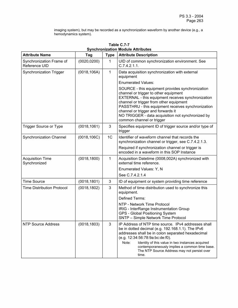
PS 3.3 - 2004 Page 263
imaging system), but may be recorded as a synchronization waveform by another device (e.g., a hemodynamics system).
Table C.7-7
Synchronization Module Attributes Attribute Name Tag Type Attribute Description Synchronization Frame of Reference UID
(0020,0200) 1 UID of common synchronization environment. See C.7.4.2.1.1.
Synchronization Trigger (0018,106A) 1 Data acquisition synchronization with external equipment Enumerated Values: SOURCE - this equipment provides synchronization channel or trigger to other equipment EXTERNAL - this equipment receives synchronization channel or trigger from other equipment PASSTHRU - this equipment receives synchronization channel or trigger and forwards it NO TRIGGER - data acquisition not synchronized by common channel or trigger
Trigger Source or Type (0018,1061) 3 Specifies equipment ID of trigger source and/or type of trigger
Synchronization Channel (0018,106C) 1C Identifier of waveform channel that records the synchronization channel or trigger, see C.7.4.2.1.3. Required if synchronization channel or trigger is encoded in a waveform in this SOP Instance
Acquisition Time Synchronized
(0018,1800) 1 Acquisition Datetime (0008,002A) synchronized with external time reference. Enumerated Values: Y, N See C.7.4.2.1.4
Time Source (0018,1801) 3 ID of equipment or system providing time reference Time Distribution Protocol (0018,1802) 3 Method of time distribution used to synchronize this
equipment. Defined Terms: NTP - Network Time Protocol IRIG - InterRange Instrumentation Group GPS - Global Positioning System SNTP – Simple Network Time Protocol
NTP Source Address (0018,1803) 3 IP Address of NTP time source. IPv4 addresses shall be in dotted decimal (e.g. 192.168.1.1). The IPv6 addresses shall be in colon separated hexadecimal (e.g. 12:34:56:78:9a:bc:de:f0).
Note: Identity of this value in two instances acquired contemporaneously implies a common time base. The NTP Source Address may not persist over time.
PS 3.3 - 2004 Page 264
C.7.4.2.1 Synchronization Attribute Descriptions C.7.4.2.1.1 Synchronization Frame of Reference UID A set of equipment may share a common acquisition synchronization environment, which is identified by a Synchronization Frame of Reference UID. All SOP Instances that share the same Synchronization Frame of Reference UID shall be temporally related to each other. If a Synchronization Frame of Reference UID is present, all SOP Instances in the Series must share the same Frame of Reference.
The UTC Synchronization UID, 1.2.840.10008.15.1.1, may be used when the equipment is synchronized to the international standard UTC. In this case the quality of synchronization may be determined by means of the Time Distribution Protocol (0018,1802) and NTP Source Address (0018,1803).
Notes: 1. The Synchronization Frame of Reference UID defines an equipment synchronization environment, and does not need to be changed for each unrelated acquisition. SOP Instances may therefore share a Synchronization Frame of Reference UID, but be clinically unrelated (e.g., apply to different patients).
2. When a synchronization environment is recalibrated, a new UID must be issued. 3. The method of distributing the Synchronization Frame of Reference UID to multiple devices is
not specified.
C.7.4.2.1.2 Time Source and Time Distribution Protocol Time may originate with a primary source (e.g., a national standards bureau) and be distributed through a chain of secondary distribution systems until reaching the imaging equipment. Time Distribution Protocol (0018,1802) specifies the immediate (last link) method used by the equipment to receive time from the immediately prior Time Source (0018,1801). It does not specify the ultimate time reference from which the Time Source may derive its synchronization.
Note: The time value distributed through the specified Time Distribution Protocol may need to be corrected to align with UTC. For example, GPS does not compensate for leap seconds.
C.7.4.2.1.3 Synchronization Channel The Synchronization Channel (0018,106C) is specified as a pair of values (M,C), where the first value is the ordinal of the sequence item of the Waveform Sequence (5400,0100) attribute (i.e., the Multiplex Group), and the second value is the ordinal of the sequence item of the Channel Definition Sequence (003A,0200) attribute (i.e., the Waveform Channel Number) within the multiplex group.
C.7.4.2.1.4 Acquisition Time Synchronized The Acquisition Time Synchronized (0018,1800) attribute specifies whether the Acquisition Datetime (0008,002A) attribute of the Waveform Identification Module or the General Image Module represents an accurate synchronized timestamp for the acquisition of the waveform and/or image data. For triggered multi-frame images, the Acquisition Datetime applies to the trigger for the first image frame (see attribute Image Trigger Delay (0018.1067) in the Cine Module).
Note: The degree of precision of the Acquisition Datetime and its accuracy relative to the external clock are not specified, but need to be appropriate for the clinical application.
For IODs that include the SR Document Content Module, the Acquisition Time Synchronized (0018,1800) attribute specifies whether the Observation Datetime (0040,A032) attribute of Items in the Content Sequence (0040,A730) of the SR Document Content Module represents an accurate synchronized timestamp for the Item.

PS 3.3 - 2004 Page 265
C.7.5 Common Equipment IE Modules The following Equipment IE Module is common to all Composite IODs that reference the Equipment IE.
C.7.5.1 General Equipment Module Table C.7-8 specifies the Attributes that identify and describe the piece of equipment that produced a Series of Composite Instances.

PS 3.3 - 2004 Page 266
Table C.7-8 GENERAL EQUIPMENT MODULE ATTRIBUTES
Attribute Name Tag Type Attribute Description Manufacturer (0008,0070) 2 Manufacturer of the equipment that
produced the composite instances. Institution Name (0008,0080) 3 Institution where the equipment that
produced the composite instances is located.
Institution Address (0008,0081) 3 Mailing address of the institution where the equipment that produced the composite instances is located.
Station Name (0008,1010) 3 User defined name identifying the machine that produced the composite instances.
Institutional Department Name (0008,1040) 3 Department in the institution where the equipment that produced the composite instances is located.
Manufacturer's Model Name (0008,1090) 3 Manufacturer’s model name of the equipment that produced the composite instances.
Device Serial Number (0018,1000) 3 Manufacturer’s serial number of the equipment that produced the composite instances.
Software Versions (0018,1020) 3 Manufacturer’s designation of software version of the equipment that produced the composite instances.
Spatial Resolution (0018,1050) 3 The inherent limiting resolution in mm of the acquisition equipment for high contrast objects for the data gathering and reconstruction technique chosen. If variable across the images of the series, the value at the image center.
Date of Last Calibration (0018,1200) 3 Date when the image acquisition device calibration was last changed in any way. Multiple entries may be used for additional calibrations at other times. See C.7.5.1.1.1 for further explanation.
Time of Last Calibration (0018,1201) 3 Time when the image acquisition device calibration was last changed in any way. Multiple entries may be used. See C.7.5.1.1.1 for further explanation.
Pixel Padding Value (0028,0120) 3 Value of pixels added to non-rectangular image to pad to rectangular format. See C.7.5.1.1.2 for further explanation.
Note: The Value Representation of this Attribute is determined by the value of Pixel Representation (0028,0103).

PS 3.3 - 2004 Page 267
C.7.5.1.1 General Equipment Attribute Descriptions C.7.5.1.1.1 Date Of Last Calibration, Time Of Last Calibration Date of Last Calibration (0018,1200) and Time of Last Calibration (0018,1201) are used to convey the date and time of calibration. The Attribute Date of Last Calibration (0018,1200) may be supported alone, however, Time of Last Calibration (0018,1201) Attribute has no meaning unless Attribute Date of Last Calibration (0018,1200) is also supported. The order for each Attribute shall be from the oldest date/time to the most recent date/time. When the Attributes are both supported they shall be provided as pairs.
C.7.5.1.1.2 Pixel Padding Value Pixel Padding Value (0028,0120) is used to pad non-rectangular images to rectangular format. The native format of some images is not rectangular. It is common for devices with this format to pad the images to the rectangular format required by the DICOM Standard with a specific pixel value that is not contained in the native image. This attribute specifies the value of this padding value.
Notes: 1. When the relationship between pixel value and X-Ray Intensity is unknown, it is recommended that the following values be used to pad with black: 0 if Photometric Interpretation (0028,0004) is MONOCHROME2. 2BitsStored - 1 if Photometric Interpretation (0028,0004) is MONOCHROME1.
2. When the relationship between pixel value and X-Ray Intensity is known (for example as defined by Pixel Intensity Relationship (0028,1040) and Pixel Intensity relationship Sign (0028,1041)), it is recommended that a value equivalent to air be used.
When modifying equipment changes the pixel padding value in the image, it shall change the value of Pixel Padding Value (0028,0120).
C.7.6 Common Image IE Modules The following Image IE Modules are common to all Composite Image IODs that reference the Image IE.
C.7.6.1 General Image Module Table C.7-9 specifies the Attributes that identify and describe an image within a particular series.

PS 3.3 - 2004 Page 268
Table C.7-9 GENERAL IMAGE MODULE ATTRIBUTES
Attribute Name Tag Type Attribute Description Instance Number (0020,0013) 2 A number that identifies this image.
Note: This Attribute was named Image Number in earlier versions of this Standard.
Patient Orientation (0020,0020) 2C Patient direction of the rows and columns of the image. Required if image does not require Image Orientation (Patient) (0020,0037) and Image Position (Patient) (0020,0032). See C.7.6.1.1.1 for further explanation.
Note: IOD’s may have attributes other than Patient Orientation, Image Orientation, or Image Position (Patient) to describe orientation in which case this attribute will be zero length.
Content Date (0008,0023) 2C The date the image pixel data creation started. Required if image is part of a series in which the images are temporally related.
Note: This Attribute was formerly known as Image Date.
Content Time (0008,0033) 2C The time the image pixel data creation started. Required if image is part of a series in which the images are temporally related.
Image Type (0008,0008) 3 Image identification characteristics. See C.7.6.1.1.2 for Defined Terms and further explanation.
Acquisition Number (0020,0012) 3 A number identifying the single continuous gathering of data over a period of time that resulted in this image.
Acquisition Date (0008,0022) 3 The date the acquisition of data that resulted in this image started
Acquisition Time (0008,0032) 3 The time the acquisition of data that resulted in this image started
Acquisition Datetime (0008,002A) 3 The date and time that the acquisition of data that resulted in this image started.
Note: The synchronization of this time with an external clock is specified in the Synchronization Module in Acquisition Time Synchronized (0018,1800).
Referenced Image Sequence (0008,1140) 3 A sequence that references other images significantly related to this image (e.g. post-localizer CT image or Mammographic biopsy or partial view images). One or more Items may be

PS 3.3 - 2004 Page 269
included in this sequence. >Referenced SOP Class UID (0008,1150) 1 Uniquely identifies the referenced SOP
Class. >Referenced SOP Instance UID (0008,1155) 1 Uniquely identifies the referenced SOP
Instance. >Referenced Frame Number (0008,1160) 3 References one or more image frames of
a Multi-frame Image SOP Instance, identifying which frames are significantly related to this image, and the reference is not to all frames.
Note: If this Attribute is not present, all frames of the SOP Instance are referenced.
>Purpose of Reference Code Sequence
(0040,A170) 3 Describes the purpose for which the reference is made. Only a single Item shall be permitted in this sequence.
>>Include ‘Code Sequence Macro’ Table 8.8-1 Defined Context ID is 7201. Derivation Description (0008,2111) 3 A text description of how this image was
derived. See C.7.6.1.1.3 for further explanation.
Derivation Code Sequence (0008,9215) 3 A coded description of how this image was derived. See C.7.6.1.1.3 for further explanation.
>Include ‘Code Sequence Macro’ Table 8.8-1 Defined Context ID is 7203. Source Image Sequence (0008,2112) 3 A Sequence that identifies the set of
Image SOP Class/Instance pairs of the Images that were used to derive this Image. Zero or more Items may be included in this Sequence. See C.7.6.1.1.4 for further explanation.
>Referenced SOP Class UID (0008,1150) 1C Uniquely identifies the referenced SOP Class. Required if Source Image Sequence (0008,2112) is sent.
>Referenced SOP Instance UID (0008,1155) 1C Uniquely identifies the referenced SOP Instance. Required if Source Image Sequence (0008,2112) is sent.
>Referenced Frame Number (0008,1160) 3 References one or more image frames of a Multi-frame Image SOP Instance, identifying which frames were used to derive this image, and the reference is not to all frames.
Note: If this Attribute is not present, all frames of the SOP Instance are referenced.
>Purpose of Reference Code Sequence
(0040,A170) 3 Describes the purpose for which the reference is made, that is what role the source image or frame(s) played in the derivation of this image. Only a single Item shall be permitted in this sequence.

PS 3.3 - 2004 Page 270
>>Include ‘Code Sequence Macro’ Table 8.8-1 Defined Context ID is 7202. Referenced Waveform Sequence (0008,113A) 3 References to waveforms acquired in
conjunction with this image. These Waveforms may or may not be temporally synchronized with this image. One or more Items may be included in this Sequence.
>Include ‘SOP Instance Reference Macro’ Table C.17-3 >Purpose of Reference Code Sequence
(0040,A170) 1 Code describing the purpose of the reference to the waveform(s). Only a single Item shall be permitted in this sequence.
>>Include 'Code Sequence Macro' Table 8.8-1 Defined Context ID is CID 7004 Images in Acquisition (0020,1002) 3 Number of images that resulted from this
acquisition of data Image Comments (0020,4000) 3 User-defined comments about the image Quality Control Image (0028,0300) 3 Indicates whether or not this image is a
quality control or phantom image. Enumerated Values: YES NO If this Attribute is absent, then the image may or may not be a quality control or phantom image.
Burned In Annotation (0028,0301) 3 Indicates whether or not image contains sufficient burned in annotation to identify the patient and date the image was acquired. Enumerated Values: YES NO If this Attribute is absent, then the image may or may not contain burned in annotation.
Lossy Image Compression (0028,2110) 3 Specifies whether an Image has undergone lossy compression. Enumerated Values:
00 = Image has NOT been subjected to lossy compression.
01 = Image has been subjected to lossy compression.
See C.7.6.1.1.5 Lossy Image Compression Ratio (0028,2112) 3 Describes the approximate lossy
compression ratio(s) that have been applied to this image. See C.7.6.1.1.5 for further explanation. May be multivalued if successive lossy

PS 3.3 - 2004 Page 271
compression steps have been applied. Notes: 1. For example, a compression
ratio of 30:1 would be described in this Attribute with a single value of 30.
2. For historical reasons, the lossy compression ratio may also be described in Derivation Description (0008,2111).
Lossy Image Compression Method (0028,2114) 3 A label for the lossy compression method(s) that have been applied to this image. See C.7.6.1.1.5 for further explanation. May be multivalued if successive lossy compression steps have been applied; the value order shall correspond to the values of Lossy Image Compression Ratio (0028,2112).
Note: For historical reasons, the lossy compression method may also be described in Derivation Description (0008,2111).
Icon Image Sequence (0088,0200) 3 This icon image is representative of the Image.
> Include ‘Image Pixel Macro’ Table C.7-11b See C.7.6.1.1.6 for further explanation. Presentation LUT Shape (2050,0020) 3 When present, specifies an identity
transformation for the Presentation LUT such that the output of all grayscale transformations, if any, are defined to be in P-Values. Enumerated Values are: IDENTITY - output is in P-Values - shall be used if Photometric Interpretation (0028,0004) is MONOCHROME2 or any color photometric interpretation. INVERSE - output after inversion is in P-Values - shall be used if Photometric Interpretation (0028,0004) is MONOCHROME1. When this attribute is used with a color photometric interpretation then the luminance component is in P-Values.
C.7.6.1.1 General Image Attribute Descriptions C.7.6.1.1.1 Patient Orientation The Patient Orientation (0020,0020) relative to the image plane shall be specified by two values that designate the anatomical direction of the positive row axis (left to right) and the positive column axis (top to bottom). The first entry is the direction of the rows, given by the direction of the last pixel in the first row from the first pixel in that row. The second entry is the direction of the

PS 3.3 - 2004 Page 272
columns, given by the direction of the last pixel in the first column from the first pixel in that column.
Anatomical direction shall be designated by the capital letters: A (anterior), P (posterior), R (right), L (left), H (head), F (foot). Each value of the orientation attribute shall contain at least one of these characters. If refinements in the orientation descriptions are to be specified, then they shall be designated by one or two additional letters in each value. Within each value, the letters shall be ordered with the principal orientation designated in the first character.
C.7.6.1.1.2 Image Type The Image Type (0008,0008) Attribute identifies important image identification characteristics. These characteristics are:
a. Pixel Data Characteristics 1. is the image an ORIGINAL Image; an image whose pixel values are based on
original or source data 2. is the image a DERIVED Image; an image whose pixel values have been derived
in some manner from the pixel value of one or more other images b. Patient Examination Characteristics
1. is the image a PRIMARY Image; an image created as a direct result of the Patient examination
2. is the image a SECONDARY Image; an image created after the initial Patient examination
c. Modality Specific Characteristics d. Implementation specific identifiers; other implementation specific identifiers shall be
documented in an implementation's conformance statement. The Image Type attribute is multi-valued and shall be provided in the following manner:
a. Value 1 shall identify the Pixel Data Characteristics; Enumerated Values for the Pixel Data Characteristics are: ORIGINAL identifies an Original Image DERIVED identifies a Derived Image
b. Value 2 shall identify the Patient Examination Characteristics; Enumerated Values for the Patient Examination Characteristics are: PRIMARY identifies a Primary Image SECONDARY identifies a Secondary Image
c. Value 3 shall identify any Image IOD specific specialization (optional) d. Other Values which are implementation specific (optional)
Any of the optional values (value 3 and beyond) may be sent either with a value or zero-length, independent of other optional values, unless otherwise specified by a specialization of this attribute in an IOD.
If the pixel data of the derived Image is different from the pixel data of the source images and this difference is expected to affect professional interpretation of the image, the Derived Image shall have a UID different than all the source images.
C.7.6.1.1.3 Derivation Description If an Image is identified to be a derived image (see C.7.6.1.1.2 Image Type), Derivation Description (0008,2111) and Derivation Code Sequence (0008,9215) describe the way in which the image was derived. They may be used whether or not the Source Image Sequence (0008,2112) is provided. They may also be used in cases when the Derived Image pixel data is
PS 3.3 - 2004 Page 273
not significantly changed from one of the source images and the SOP Instance UID of the Derived Image is the same as the one used for the source image.
Notes: 1. Examples of Derived Images that would normally be expected to affect professional interpretation and would thus have a new UID include:
a. images resulting from image processing of another image (e.g. unsharp masking), b. a multiplanar reformatted CT image, c. a DSA image derived by subtracting pixel values of one image from another.
d. an image that has been decompressed after having been compressed with a lossy compression algorithm. To ensure that the user has the necessary information about the lossy compression, the approximate compression ratio may be included in Derivation Description (0008,2111).
An example of a Derived Image that would normally not be expected to affect professional interpretation and thus would not require a new UID is an image that has been padded with additional rows and columns for more display purposes.
2. An image may be lossy compressed, e.g., for long term archive purposes, and its SOP Instance UID changed. PS3.4 provides a mechanism by which a query for the original image Instance may return a reference to the UID of the lossy compressed version of the image using the Alternate Representation Sequence (0008,3001). This allows an application processing a SOP Instance that references the original image UID, e.g., a Structured Report, to obtain a reference to an accessible version of the image even if the original SOP Instance is no longer available.
C.7.6.1.1.4 Source image sequence If an Image is identified to be a Derived image (see C.7.6.1.1.2 Image Type), Source Image Sequence (0008,2112) is an optional list of Referenced SOP Class UID (0008,1150)/ Referenced SOP Instance UID (0008,1150) pairs that identify the source images used to create the Derived image. It may be used whether or not there is a description of the way the image was derived in Derivation Description (0008,2111) or Derivation Code Sequence (0008,9215).
C.7.6.1.1.5 Lossy Image Compression The Attribute Lossy Image Compression (0028,2110) conveys that the Image has undergone lossy compression. It provides a means to record that the Image has been compressed (at a point in its lifetime) with a lossy algorithm and changes have been introduced into the pixel data. Once the value has been set to “01”, it shall not be reset.
Note: If an image is compressed with a lossy algorithm, the attribute Lossy Image Compression (0028,2110) is set to “01”. Subsequently, if the image is decompressed and transferred in uncompressed format, this attribute value remains “01”.
The value of the Lossy Image Compression (0028,2110) Attribute in SOP Instances containing multiple frames in which one or more of the frames have undergone lossy compression shall be “01”.
Note: It is recommended that the applicable frames be noted in the Attribute Derivation Description (0008,2111).
If an image is originally obtained as a lossy compressed image from the sensor, then Lossy Image Compression (0028,2110) is set to “01” and Value 1 of the Attribute Image Type (0008,0008) shall be set to ORIGINAL.
If an image is a compressed version of another image, Lossy Image Compression (0028,2110) is set to “01”, Value 1 of the Attribute Image Type (0008,0008) shall be set to DERIVED, and if the predecessor was a DICOM image, then the Image shall receive a new SOP Instance UID.

PS 3.3 - 2004 Page 274
Note: 1. It is recommended that the approximate compression ratio be provided in the Attribute Derivation Description (0008,2111). Furthermore, it is recommended that Derivation Description (0008,2111) be used to indicate when pixel data changes might affect professional interpretation. (see C.7.6.1.1.3).
2. The attribute Lossy Image Compression (0028,2110) is defined as Type 3 for backward compatibility with existing IODs. It is expected to be required (i.e., defined as Type 1C) for new Image IODs and for existing IODs that undergo a major revision (e.g. a new IOD is specified).
The Defined Terms for Lossy Image Compression Method (0028,2114) are:
ISO_10918_1 = JPEG Lossy Compression ISO_14495_1 = JPEG-LS Near-lossless Compression ISO_15444_1 = JPEG 2000 Irreversible Compression ISO_13818_2 = MPEG2 Compression
C.7.6.1.1.6 Icon Image Sequence An Icon Image may be used as a key representative of an Image. It is defined as a Sequence that contains a single Item encapsulating the Data Set made of the Data Elements of the Icon Image. The Data Elements are defined by the Image Pixel Macro (see Section C.7.6.3). The restrictions defined in Section F.7 shall apply.
C.7.6.2 Image Plane Module Table C.7-10 specifies the Attributes that define the transmitted pixel array of a two dimensional image plane.
Note: In previous versions of this Standard, image position and image orientation were specified relative to a specific equipment coordinate system. This equipment coordinate system was not fully defined and a number of ambiguities existed. The equipment based coordinate system has been retired and replaced by the patient based coordinate system defined in this Module.
Table C.7-10
IMAGE PLANE MODULE ATTRIBUTES Attribute Name Tag Type Attribute Description Pixel Spacing (0028,0030) 1 Physical distance in the patient between
the center of each pixel, specified by a numeric pair - adjacent row spacing (delimiter) adjacent column spacing in mm.
Image Orientation (Patient) (0020,0037) 1 The direction cosines of the first row and the first column with respect to the patient. See C.7.6.2.1.1 for further explanation.
Image Position (Patient) (0020,0032) 1 The x, y, and z coordinates of the upper left hand corner (center of the first voxel transmitted) of the image, in mm. See C.7.6.2.1.1 for further explanation.
Slice Thickness (0018,0050) 2 Nominal slice thickness, in mm. Slice Location (0020,1041) 3 Relative position of exposure expressed in
mm. C.7.6.2.1.2 for further explanation.

PS 3.3 - 2004 Page 275
C.7.6.2.1 Image Plane Attribute Descriptions C.7.6.2.1.1 Image Position And Image Orientation The Image Position (0020,0032) specifies the x, y, and z coordinates of the upper left hand corner of the image; it is the center of the first voxel transmitted. Image Orientation (0020,0037) specifies the direction cosines of the first row and the first column with respect to the patient. These Attributes shall be provide as a pair. Row value for the x, y, and z axes respectively followed by the Column value for the x, y, and z axes respectively.
The direction of the axes is defined fully by the patient’s orientation. The x-axis is increasing to the left hand side of the patient. The y-axis is increasing to the posterior side of the patient. The z-axis is increasing toward the head of the patient.
The patient based coordinate system is a right handed system, i.e. the vector cross product of a unit vector along the positive x-axis and a unit vector along the positive y-axis is equal to a unit vector along the positive z-axis.
Note: If a patient lies parallel to the ground, face-up on the table, with his feet-to-head direction same as the front-to-back direction of the imaging equipment, the direction of the axes of this patient based coordinate system and the equipment based coordinate system in previous versions of this Standard will coincide.
The Image Plane Attributes, in conjunction with the Pixel Spacing Attribute, describe the position and orientation of the image slices relative to the patient-based coordinate system. In each image frame the Image Position (Patient) (0020,0032) specifies the origin of the image with respect to the patient-based coordinate system. RCS and the Image Orientation (Patient) (0020,0037) attribute values specify the orientation of the image frame rows and columns. The mapping of pixel location ( )ji, to the RCS is calculated as follows:
∆∆∆∆∆∆
=
10
1000000
1
ji
SjYiXSjYiXSjYiX
PPP
zzz
yyy
xxx
z
y
x
= M
10ji
Where:
Pxyz The coordinates of the voxel (i,j) in the frame’s image plane in units of mm. Sxyz The three values of the Image Position (Patient) (0020,0032) attributes. It is the
location in mm from the origin of the RCS. Xxyz The values from the row (X) direction cosine of the Image Orientation (Patient)
(0020,0037) attribute. Yxyz The values from the column (Y) direction cosine of the Image Orientation (Patient)
(0020,0037) attribute. i Column index to the image plane. The first column is index zero. ∆i Column pixel resolution of the Pixel Spacing (0028,0030) attribute in units of mm. j Row index to the image plane. The first row index is zero. ∆j Row pixel resolution of the Pixel Spacing (0028,0030) attribute in units of mm.
Additional constraints apply:

PS 3.3 - 2004 Page 276
1) The row and column direction cosine vectors shall be orthogonal, i.e. their dot product shall be zero.
2) The row and column direction cosine vectors shall be normal, i.e. the dot product of each direction cosine vector with itself shall be unity.
C.7.6.2.1.2 Slice Location The Slice Location (0020,1041) is defined as the relative position of exposure expressed in mm. This information is relative to an unspecified implementation specific reference point.
C.7.6.3 Image Pixel Module Table C.7-11a describes the Image Pixel Module.
Table C.7-11a IMAGE PIXEL MODULE ATTRIBUTES
Attribute Name Tag Type Attribute Description Include ‘Image Pixel Macro’ Table C.7-11b
Table C.7-11b specifies the common attributes that describe the pixel data of the image.
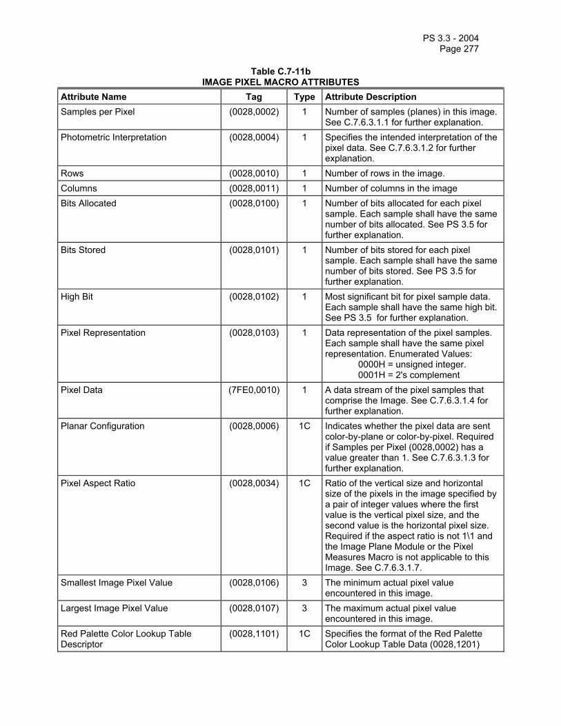
PS 3.3 - 2004 Page 277
Table C.7-11b IMAGE PIXEL MACRO ATTRIBUTES
Attribute Name Tag Type Attribute Description Samples per Pixel (0028,0002) 1 Number of samples (planes) in this image.
See C.7.6.3.1.1 for further explanation. Photometric Interpretation (0028,0004) 1 Specifies the intended interpretation of the
pixel data. See C.7.6.3.1.2 for further explanation.
Rows (0028,0010) 1 Number of rows in the image. Columns (0028,0011) 1 Number of columns in the image Bits Allocated (0028,0100) 1 Number of bits allocated for each pixel
sample. Each sample shall have the same number of bits allocated. See PS 3.5 for further explanation.
Bits Stored (0028,0101) 1 Number of bits stored for each pixel sample. Each sample shall have the same number of bits stored. See PS 3.5 for further explanation.
High Bit (0028,0102) 1 Most significant bit for pixel sample data. Each sample shall have the same high bit. See PS 3.5 for further explanation.
Pixel Representation (0028,0103) 1 Data representation of the pixel samples. Each sample shall have the same pixel representation. Enumerated Values: 0000H = unsigned integer. 0001H = 2's complement
Pixel Data (7FE0,0010) 1 A data stream of the pixel samples that comprise the Image. See C.7.6.3.1.4 for further explanation.
Planar Configuration (0028,0006) 1C Indicates whether the pixel data are sent color-by-plane or color-by-pixel. Required if Samples per Pixel (0028,0002) has a value greater than 1. See C.7.6.3.1.3 for further explanation.
Pixel Aspect Ratio (0028,0034) 1C Ratio of the vertical size and horizontal size of the pixels in the image specified by a pair of integer values where the first value is the vertical pixel size, and the second value is the horizontal pixel size. Required if the aspect ratio is not 1\1 and the Image Plane Module or the Pixel Measures Macro is not applicable to this Image. See C.7.6.3.1.7.
Smallest Image Pixel Value (0028,0106) 3 The minimum actual pixel value encountered in this image.
Largest Image Pixel Value (0028,0107) 3 The maximum actual pixel value encountered in this image.
Red Palette Color Lookup Table Descriptor
(0028,1101) 1C Specifies the format of the Red Palette Color Lookup Table Data (0028,1201)
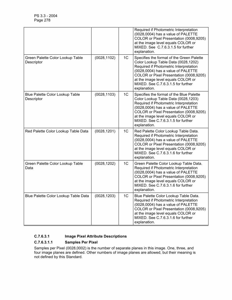
PS 3.3 - 2004 Page 278
Required if Photometric Interpretation (0028,0004) has a value of PALETTE COLOR or Pixel Presentation (0008,9205) at the image level equals COLOR or MIXED. See C.7.6.3.1.5 for further explanation.
Green Palette Color Lookup Table Descriptor
(0028,1102) 1C Specifies the format of the Green Palette Color Lookup Table Data (0028,1202) Required if Photometric Interpretation (0028,0004) has a value of PALETTE COLOR or Pixel Presentation (0008,9205) at the image level equals COLOR or MIXED. See C.7.6.3.1.5 for further explanation.
Blue Palette Color Lookup Table Descriptor
(0028,1103) 1C Specifies the format of the Blue Palette Color Lookup Table Data (0028,1203) Required if Photometric Interpretation (0028,0004) has a value of PALETTE COLOR or Pixel Presentation (0008,9205) at the image level equals COLOR or MIXED. See C.7.6.3.1.5 for further explanation.
Red Palette Color Lookup Table Data (0028,1201) 1C Red Palette Color Lookup Table Data. Required if Photometric Interpretation (0028,0004) has a value of PALETTE COLOR or Pixel Presentation (0008,9205) at the image level equals COLOR or MIXED. See C.7.6.3.1.6 for further explanation.
Green Palette Color Lookup Table Data
(0028,1202) 1C Green Palette Color Lookup Table Data. Required if Photometric Interpretation (0028,0004) has a value of PALETTE COLOR or Pixel Presentation (0008,9205) at the image level equals COLOR or MIXED. See C.7.6.3.1.6 for further explanation.
Blue Palette Color Lookup Table Data (0028,1203) 1C Blue Palette Color Lookup Table Data. Required if Photometric Interpretation (0028,0004) has a value of PALETTE COLOR or Pixel Presentation (0008,9205) at the image level equals COLOR or MIXED. See C.7.6.3.1.6 for further explanation.
C.7.6.3.1 Image Pixel Attribute Descriptions C.7.6.3.1.1 Samples Per Pixel Samples per Pixel (0028,0002) is the number of separate planes in this image. One, three, and four image planes are defined. Other numbers of image planes are allowed, but their meaning is not defined by this Standard.
PS 3.3 - 2004 Page 279
For monochrome (gray scale) and palette color images, the number of planes is 1. For RGB and other three vector color models, the value of this attribute is 3. For four vector color models, the value of this attribute is 4.
All image planes shall have the same number of Rows (0028,0010), Columns (0028,0011), Bits Allocated (0028,0100), Bits Stored (0028,0101), High Bit (0028,0102), Pixel Representation (0028,0103), and Pixel Aspect Ratio (0028,0034).
The data in each pixel may be represented as a “Composite Pixel Code”. If Samples Per Pixel is one, the Composite Pixel Code is just the “n” bit pixel sample, where “n” = Bits Allocated. If Samples Per Pixel is greater than one, Composite Pixel Code is a “k” bit concatenation of samples, where “k” = Bits Allocated multiplied by Samples Per Pixel, and with the sample representing the vector color designated first in the Photometric Interpretation name comprising the most significant bits of the Composite Pixel Code, followed in order by the samples representing the next vector colors, with the sample representing the vector color designated last in the Photometric Interpretation name comprising the least significant bits of the Composite Pixel Code. For example, for Photometric Interpretation = “RGB”, the most significant “Bits Allocated” bits contain the Red sample, the next “Bits Allocated” bits contain the Green sample, and the least significant “Bits Allocated” bits contain the Blue sample.
C.7.6.3.1.2 Photometric Interpretation The value of Photometric Interpretation (0028,0004) specifies the intended interpretation of the image pixel data.
See PS 3.5 for restrictions imposed by compressed Transfer Syntaxes.
The following values are defined. Other values are permitted but the meaning is not defined by this Standard.
MONOCHROME1 = Pixel data represent a single monochrome image plane. The minimum sample value is intended to be displayed as white after any VOI gray scale transformations have been performed. See PS 3.4. This value may be used only when Samples per Pixel (0028,0002) has a value of 1.
MONOCHROME2 = Pixel data represent a single monochrome image plane. The minimum sample value is intended to be displayed as black after any VOI gray scale transformations have been performed. See PS 3.4. This value may be used only when Samples per Pixel (0028,0002) has a value of 1.
PALETTE COLOR = Pixel data describe a color image with a single sample per pixel (single image plane). The pixel value is used as an index into each of the Red, Blue, and Green Palette Color Lookup Tables (0028,1101-1103&1201-1203). This value may be used only when Samples per Pixel (0028,0002) has a value of 1. When the Photometric Interpretation is Palette Color; Red, Blue, and Green Palette Color Lookup Tables shall be present.
RGB = Pixel data represent a color image described by red, green, and blue image planes. The minimum sample value for each color plane represents minimum intensity of the color. This value may be used only when Samples per Pixel (0028,0002) has a value of 3.
HSV = Retired.
ARGB = Retired.
CMYK = Retired.
YBR_FULL = Pixel data represent a color image described by one luminance (Y) and two chrominance planes (CB and CR). This photometric interpretation may be used only when

PS 3.3 - 2004 Page 280
Samples per Pixel (0028,0002) has a value of 3. Black is represented by Y equal to zero. The absence of color is represented by both CB and CR values equal to half full scale.
Note: In the case where the Bits Allocated (0028,0100) has value of 8 half full scale is 128.
In the case where Bits Allocated (0028,0100) has a value of 8 then the following equations convert between RGB and YCBCR Photometric Interpretation.
Y = + .2990R + .5870G + .1140B
CB = - .1687R - .3313G + .5000B + 128
CR = + .5000R - .4187G - .0813B + 128
Note: The above is based on CCIR Recommendation 601-2 dated 1990.
YBR_FULL_422 = The same as YBR_FULL except that the CB and CR values are sampled horizontally at half the Y rate and as a result there are half as many CB and CR values as Y values.
This Photometric Interpretation is only allowed with Planar Configuration (0028,0006) equal to 0. Two Y values shall be stored followed by one CB and one CR value. The CB and CR values shall be sampled at the location of the first of the two Y values. For each Row of Pixels, the first CB and CR samples shall be at the location of the first Y sample. The next CB and CR samples shall be at the location of the third Y sample etc.
Note: This subsampling is often referred to as cosited sampling.
YBR_PARTIAL_422 = The same as YBR_FULL_422 except that:
1. black corresponds to Y = 16; 2. Y is restricted to 220 levels (i.e. the maximum value is 235); 3. CB and CR each has a minimum value of 16;
4. CB and CR are restricted to 225 levels (i.e. the maximum value is 240);
5. lack of color is represented by CB and CR equal to 128.
In the case where Bits Allocated (0028,0100) has value of 8 then the following equations convert between RGB and YBR_PARTIAL_422 Photometric Interpretation
Y = + .2568R + .5041G + .0979B + 16
CB = - .1482R - .2910G + .4392B + 128
CR = + .4392R - .3678G - .0714B + 128
Note: The above is based on CCIR Recommendation 601-2 dated 1990.
YBR_PARTIAL_420 = The same as YBR_PARTIAL_422 except that the CB and CR values are sampled horizontally and vertically at half the Y rate and as a result there are four times less CB and CR values than Y values, versus twice less for YBR_PARTIAL_422.

PS 3.3 - 2004 Page 281
This Photometric Interpretation is only allowed with Planar Configuration (0028,0006) equal to 0. The CB and CR values shall be sampled at the location of the first of the two Y values. For the first Row of Pixels (etc.), the first CB and CR samples shall be at the location of the first Y sample. The next CB and CR samples shall be at the location of the third Y sample etc. The next Rows of Pixels containing CB and CR samples (at the same locations than for the first Row) will be the third etc.
YBR_ICT = Irreversible Color Transformation:
Pixel data represent a color image described by one luminance (Y) and two chrominance planes (CB and CR). This photometric interpretation may be used only when Samples per Pixel (0028,0002) has a value of 3. Black is represented by Y equal to zero. The absence of color is represented by both CB and CR values equal to zero.
Regardless of the value of Bits Allocated (0028,0100), the following equations convert between RGB and YCBCR Photometric Interpretation.
Y = + .29900R + .58700G + .11400B
CB = - .16875R - .33126G + .50000B
CR = + .50000R - .41869G - .08131B
Notes: 1. The above is based on ISO/IEC 15444-1 (JPEG 2000). 2. In a JPEG 2000 bitstream, DC level shifting (used if the untransformed components are
unsigned) is applied before forward color transformation, and the transformed components may be signed (unlike in JPEG ISO/IEC 10918-1).
3. In JPEG 2000, spatial down-sampling of the chrominance components, if performed, is signaled in the JPEG 2000 bitstream.
YBR_RCT = Reversible Color Transformation:
Pixel data represent a color image described by one luminance (Y) and two chrominance planes (CB and CR). This photometric interpretation may be used only when Samples per Pixel (0028,0002) has a value of 3. Black is represented by Y equal to zero. The absence of color is represented by both CB and CR values equal to zero.
Regardless of the value of Bits Allocated (0028,0100), the following equations convert between RGB and YBR_RCT Photometric Interpretation.
Y = (R + 2G +B) / 4 (Note: ... mean floor)
CB = B - G
CR = R - G
The following equations convert between YBR_RCT and RGB Photometric Interpretation.
G = Y – (CR + CB) / 4
R = CR + G
B = CB + G

PS 3.3 - 2004 Page 282
Notes: 1. The above is based on ISO/IEC 15444-1 (JPEG 2000). 2. In a JPEG 2000 bitstream, DC level shifting (used if the untransformed components are
unsigned) is applied before forward color transformation, and the transformed components may be signed (unlike in JPEG ISO/IEC 10918-1).
3. This photometric interpretation is a reversible approximation to the YUV transformation used in PAL and SECAM.
C.7.6.3.1.3 Planar Configuration Planar Configuration (0028,0006) indicates whether the color pixel data are sent color-by-plane or color-by-pixel. This Attribute shall be present if Samples per Pixel (0028,0002) has a value greater than 1. It shall not be present otherwise.
Enumerated Values:
0 = The sample values for the first pixel are followed by the sample values for the second pixel, etc. For RGB images, this means the order of the pixel values sent shall be R1, G1, B1, R2, G2, B2, ..., etc.
1 = Each color plane shall be sent contiguously. For RGB images, this means the order of the pixel values sent is R1, R2, R3, ..., G1, G2, G3, ..., B1, B2, B3, etc.
Note: Planar Configuration (0028,0006) is not meaningful when a compression transfer syntax is used that involves reorganization of sample components in the compressed bit stream. In such cases, since the Attribute is required to be sent, then an appropriate value to use may be specified in the description of the Transfer Syntax in PS 3.5, though in all likelihood the value of the Attribute will be ignored by the receiving implementation.
C.7.6.3.1.4 Pixel Data Pixel Data (7FE0,0010) for this image. The order of pixels sent for each image plane is left to right, top to bottom, i.e., the upper left pixel (labeled 1,1) is sent first followed by the remainder of row 1, followed by the first pixel of row 2 (labeled 2,1) then the remainder of row 2 and so on.
For multi-plane images see Planar Configuration (0028,0006) in this Section.
C.7.6.3.1.5 Palette Color Lookup Table Descriptor The three values of Palette Color Lookup Table Descriptor (0028,1101-1103) describe the format of the Lookup Table Data in the corresponding Data Element (0028,1201-1203) or (0028,1221-1223).
The first value is the number of entries in the lookup table. When the number of table entries is equal to 216 then this value shall be 0. The first value shall be identical for each of the Red, Green and Blue Palette Color Lookup Table Descriptors.
The second value is the first stored pixel value mapped. This pixel value is mapped to the first entry in the Lookup Table Data. All image pixel values less than the first value mapped are also mapped to the first entry in the Lookup Table Data if the Photometric Interpretation is PALETTE COLOR.
Note: In the case of the Supplemental Palette Color LUT, the stored pixel values less than the second descriptor value are grayscale values.
An image pixel value one greater than the first value mapped is mapped to the second entry in the Lookup Table Data. Subsequent image pixel values are mapped to the subsequent entries in the Lookup Table Data up to an image pixel value equal to number of entries + first value mapped – 1, which is mapped to the last entry in the Lookup Table Data. Image pixel values greater than or equal to number of entries + first value mapped are also mapped to the last entry

PS 3.3 - 2004 Page 283
in the Lookup Table Data. The second value shall be identical for each of the Red, Green and Blue Palette Color Lookup Table Descriptors.
The third value specifies the number of bits for each entry in the Lookup Table Data. It shall take the value of 8 or 16. The LUT Data shall be stored in a format equivalent to 8 or 16 bits allocated where the high bit is equal to bits allocated-1. The third value shall be identical for each of the Red, Green and Blue Palette Color Lookup Table Descriptors.
When the Palette Color Lookup Table Descriptor (0028,1101-1103) are used as part of the Palette Color Lookup Table Module or the Supplemental Palette Color Lookup Table Module, the third value shall be equal to 16.
Notes: 1. A value of 16 indicates the Lookup Table Data will range from (0,0,0) minimum intensity to (65535,65535,65535) maximum intensity.
2. Since the Palette Color Lookup Table Descriptor (0028,1101-1103) Attributes are multi-valued, in an Explicit VR Transfer Syntax, only one value representation (US or SS) may be specified, even though the first and third values are always by definition interpreted as unsigned. The explicit VR actually used is dictated by the VR needed to represent the second value, which will be consistent with Pixel Representation (0028,0103).
C.7.6.3.1.6 Palette Color Lookup Table Data Palette Color Lookup Table Data (0028,1201-1203) contain the lookup table data corresponding to the Lookup Table Descriptor (0028,1101-1103).
Palette color values must always be scaled across the full range of available intensities. This is indicated by the fact that there are no bits stored and high bit values for palette color data.
Note: For example, if there are 16 bits per entry specified and only 8 bits of value are truly used then the 8 bit intensities from 0 to 255 must be scaled to the corresponding 16 bit intensities from 0 to 65535. To do this for 8 bit values, simply replicate the value in both the most and least significant bytes.
These lookup tables shall be used only when there is a single sample per pixel (single image plane) in the image.
These lookup tables are required when the value of Photometric Interpretation (0028,0004) is Palette Color. The semantics of these lookup tables is not defined otherwise.

PS 3.3 - 2004 Page 284
C.7.6.3.1.7 Pixel Aspect Ratio The pixel aspect ratio is the ratio of the vertical size and horizontal size of the pixels in the image specified by a pair of integer values where the first value is the vertical pixel size, and the second value is the horizontal pixel size. To illustrate, consider the following example pixel size:
H = 0.25 mm
V =
Dimensions of pixel
0.30 mm
Pixel Aspect Ratio = Vertical Size \ Horizontal Size = 0.30 mm \0.25 mm. Thus the Pixel Aspect Ratio could be represented as the multivalued integer string "6\5", "60\50", or any equivalent integer ratio.
C.7.6.4 Contrast/Bolus Module Table C.7-12 specifies the Attributes that describe the contrast /bolus used in the acquisition of the Image.
Table C.7-12 CONTRAST/BOLUS MODULE ATTRIBUTES
Attribute Name Tag Type Attribute Description Contrast/Bolus Agent (0018,0010) 2 Contrast or bolus agent Contrast/Bolus Agent Sequence (0018,0012) 3 Sequence that identifies the contrast
agent. One or more Items may be present. >Include ‘Code Sequence Macro’ Table 8.8-1 Baseline Context ID is 12. Contrast/Bolus Route (0018,1040) 3 Administration route of contrast agent Contrast/Bolus Administration Route Sequence
(0018,0014) 3 Sequence that identifies the route of administration of contrast agent. Only a single Item shall be permitted in this sequence.
>Include ‘Code Sequence Macro’ Table 8.8-1 Baseline Context ID is 11. >Additional Drug Sequence (0018,002A) 3 Sequence that identifies any additional
drug that is administered with the contrast agent bolus. One or more Items may be present.
>>Include ‘Code Sequence Macro’ Table 8.8-1 No Baseline Context ID is defined. Contrast/Bolus Volume (0018,1041) 3 Volume injected in milliliters of diluted
contrast agent Contrast/Bolus Start Time (0018,1042) 3 Time of start of injection Contrast/Bolus Stop Time (0018,1043) 3 Time of end of contrast injection Contrast/Bolus Total Dose (0018,1044) 3 Total amount in milliliters of the undiluted

PS 3.3 - 2004 Page 285
contrast agent Contrast Flow Rate (0018,1046) 3 Rate(s) of injection(s) in milliliters/sec Contrast Flow Duration (0018,1047) 3 Duration(s) of injection(s) in seconds. Each
Contrast Flow Duration value shall correspond to a value of Contrast Flow Rate (0018,1046).
Contrast/Bolus Ingredient (0018,1048) 3 Active ingredient of agent. Defined Terms: IODINE GADOLINIUM CARBON DIOXIDE BARIUM
Contrast/Bolus Ingredient Concentration
(0018,1049) 3 Milligrams of active ingredient per milliliter of (diluted) agent
Note: 1. Flow duration is an alternate method of specifying stop time 2. Flow rate allows for stepped injections by being capable of multiple values (1,N) instances. 3. For a 100 ml injection of 76% Diatrizoate and meglumine/sodium, diluted 1:1, the Contrast/Bolus Agent would be “76% Diatrizoate” as text the Contrast/Bolus Volume would be 100 ml, the Contrast/Bolus Total Dose would be 50 ml, the Contrast/Bolus Ingredient would be “IODINE”, the Contrast/Bolus Ingredient Concentration would be 370mg/ml.
C.7.6.4b Enhanced Contrast/Bolus Module Table C.7-12b specifies the Attributes that describe the contrast/bolus used in the acquisition of the Image.
Table C.7-12b ENHANCED CONTRAST/BOLUS MODULE ATTRIBUTES
Attribute Name Tag Type Attribute Description Contrast/Bolus Agent Sequence (0018,0012) 1 Sequence that identifies one or more
contrast agents administered prior to or during the acquisition. Shall contain one or more Items.
>Include ‘Code Sequence Macro’ Table 8.8-1 Baseline Context ID is 12. >Contrast/Bolus Agent Number (0018,9337) 1 Identifying number, unique within this SOP
Instance, of the agent administered. Used to reference this particular agent from the Contrast/Bolus Functional Group Macro.
>Contrast/Bolus Administration Route Sequence
(0018,0014) 1 Sequence that identifies the route of administration of contrast agent. Shall contain exactly one Item.
>>Include ‘Code Sequence Macro’ Table 8.8-1 Baseline Context ID is 11. >Contrast/Bolus Ingredient Code Sequence
(0018,9338) 2 Active ingredient of agent. Zero or more Items may be included in the Sequence.
>>Include ‘Code Sequence Macro’ Table 8.8-1 Baseline Context ID is 13. >Contrast/Bolus Volume (0018,1041) 2 Total volume administered in milliliters of

PS 3.3 - 2004 Page 286
diluted contrast agent. >Contrast/Bolus Ingredient Concentration
(0018,1049) 2 Milligrams of active ingredient per milliliter of agent.
>Contrast Administration Profile Sequence
(0018,9340) 3 Sequence that describes one or more phases of contrast administered. If present, shall contain one or more Items.
>>Contrast/Bolus Volume (0018,1041) 2 Volume administered during this phase in milliliters of diluted contrast agent.
>>Contrast/Bolus Start Time (0018,1042) 3 Time of start of administration. >>Contrast/Bolus Stop Time (0018,1043) 3 Time of end of administration. >>Contrast Flow Rate (0018,1046) 3 Rate of administration in milliliters/sec.
Only a single value shall be present. >>Contrast Flow Duration (0018,1047) 3 Duration of injection in seconds. Only a
single value shall be present.
C.7.6.5 Cine Module
Table C.7-13 specifies the Attributes of a Multi-frame Cine Image. Table C.7-13
CINE MODULE ATTRIBUTES Attribute Name Tag Type Attribute Description Preferred Playback Sequencing (0018,1244) 3 Describes the preferred playback
sequencing for a multi-frame image. Enumerated Values: 0 = Looping (1,2...n,1,2,...n,1,2,....n,...) 1 = Sweeping (1,2,...n,n-1,...2,1,2,...n,...)
Frame Time (0018,1063) 1C Nominal time (in msec) per individual frame. See C.7.6.5.1.1 for further explanation. Required if Frame Increment Pointer (0028,0009) points to Frame Time.
Frame Time Vector (0018,1065) 1C An array that contains the real time increments (in msec) between frames for a Multi-frame image. See C.7.6.5.1.2 for further explanation. Required if Frame Increment Pointer (0028,0009) points to Frame Time Vector.
Start Trim (0008,2142) 3 The frame number of the first frame of the Multi-frame image to be displayed.
Stop Trim (0008,2143) 3 The Frame Number of the last frame of a Multi-frame image to be displayed.
Recommended Display Frame Rate (0008,2144) 3 Recommended rate at which the frames of a Multi-frame image should be displayed in frames/second.
Cine Rate (0018,0040) 3 Number of frames per second. Frame Delay (0018,1066) 3 Time (in msec) from Content Time
(0008,0033) to the start of the first frame in a Multi-frame image.

PS 3.3 - 2004 Page 287
Image Trigger Delay (0018,1067) 3 Delay time in milliseconds from trigger (e.g., X-ray on pulse) to the first frame of a Multi-frame image.
Effective Duration (0018,0072) 3 Total time in seconds that data was actually taken for the entire Multi-frame image.
Actual Frame Duration (0018,1242) 3 Elapsed time of data acquisition in msec per each frame.
Multiplexed Audio Channels Description Code Sequence
(003A,0300) 1C Description of any multiplexed audio channels. See Section C.7.6.5.1.3. Required if the Transfer Syntax used to encode the multi-frame image contains multiplexed (interleaved) audio channels, such as is possible with MPEG2.
>Channel Identification Code (003A,0301) 1 A reference to the audio channel as identified within Transfer Syntax encoded bit stream (1 for the main channel, 2 for the second channel and 3 to 9 to the complementary channels).
>Channel Mode (003A,0302) 1 A coded descriptor qualifying the mode of the channel: Enumerated Values:
MONO = 1 signal STEREO = 2 simultaneously acquired (left and right) signals
>Channel Source Sequence (003A,0208) 1 A coded descriptor of the audio channel source. Only a single Item shall be permitted in this sequence.
>>Include 'Code Sequence Macro' Table 8.8-1. Defined Context ID Audio Channel Source 3000.
C.7.6.5.1 Cine Attribute Descriptions C.7.6.5.1.1 Frame Time Frame Time (0018,1063) is the nominal time (in milliseconds) between individual frames of a Multi-frame image. If the Frame Increment Pointer points to this Attribute, Frame Time shall be used in the following manner to calculate 'the relative time' for each frame:
Frame 'Relative Time' (n) = Frame Delay + Frame Time * (n-1)
where: n = number of frame within the Multi-frame image and the first frame number is one
C.7.6.5.1.2 Frame Time Vector Frame Time Vector (0018,1065) is an array that contains the time increments (in milliseconds) between the nth frame and the previous frame for a Multi-frame image. The first frame always has a time increment of 0. If the Frame Increment Pointer points to this Attribute, the Frame Time Vector shall be used in the following manner to calculate 'relative time' T(n) for frame n:

PS 3.3 - 2004 Page 288
T(n) = t
n
∑ ∆ ii=1
where ∆ti is the ith Frame Time Vector component.
C.7.6.5.1.3 Multiplexed Audio During a video acquisition, audio may be used for voice commentary of what is being observed, as well as to record sound-based physiological information such as Doppler audio.
Some Transfer Syntaxes allow for the multiplexing of interleaved audio with video data, and the Attributes of the Cine Module support this encoding paradigm. They are not intended to describe audio acquired simultaneously when it is encoded in other SOP Instances or within Attributes other than Pixel Data (7FE0,0010) of the same SOP Instance.
Synchronization between audio and video is assumed to be encoded at the Transfer Syntax level (i.e. within the encoded bit stream).
C.7.6.6 Multi-Frame Module Table C.7-14 specifies the Attributes of a Multi-frame pixel data Image.
Table C.7-14 MULTI-FRAME MODULE ATTRIBUTES
Attribute Name Tag Type Attribute Description Number of Frames (0028,0008) 1 Number of frames in a Multi-frame
Image. See C.7.6.6.1.1 for further explanation.
Frame Increment Pointer (0028,0009) 1 Contains the Data Element Tag of the attribute that is used as the frame increment in Multi-frame pixel data. See C.7.6.6.1.1 for further explanation.
C.7.6.6.1 Multi-Frame Attribute Descriptions C.7.6.6.1.1 Number Of Frames And Frame Increment Pointer A Multi-frame Image is defined as a Image whose pixel data consists of a sequential set of individual Image Pixel frames. A Multi-frame Image is transmitted as a single contiguous stream of pixels. Frame headers do not exist within the data stream.
Each individual frame shall be defined (and thus can be identified) by the Attributes in the Image Pixel Module (see C.7.6.3). All Image IE Attributes shall be related to the first frame in the Multi-frame image.
The total number of frames contained within a Multi-frame Image is conveyed in the Number of Frames (0028,0008).
The frames within a Multi-frame Image shall be conveyed as a logical sequence. The information that determines the sequential order of the frames shall be identified by the Data Element Tag or tags conveyed by the Frame Increment Pointer (0028,0009). Each specific Image IOD that supports the Multi-frame Module specializes the Frame Increment Pointer (0028,0009) to identify the Attributes that may be used as sequences.

PS 3.3 - 2004 Page 289
C.7.6.7 Bi-Plane Sequence Module (Retired) C.7.6.8 Bi-Plane Image Module (Retired) C.7.6.9 Frame Pointers Module Table C.7-15 specifies the attributes of a Frame Pointer Module.
Table C.7-15 FRAME POINTERS MODULE ATTRIBUTES
Attribute Name Tag Type Attribute Description Representative Frame Number (0028,6010) 3 The frame number selected for use as
a pictorial representation (e.g. icon) of the Multi-frame Image
Frame Numbers Of Interest (FOI) (0028,6020) 3 Frame number(s) selected as frames of interest. A frame number may appear more than once.
Frame Of Interest Description (0028,6022) 3 Description of each one of the Frame(s) of Interest selected in (0028,6020). If multiple Frames of Interest are selected and this Attribute is used, it shall contain the same number of values as are in Frame Numbers of Interest (0028,6020).
Frame of Interest Type (0028,6023) 3 A defined term for each one of the Frame(s) of Interest (0028,6020) that identifies the significance of the frame. If multiple Frames of Interest are selected and this Attribute is used, it shall contain the same number of values as are in Frame Numbers of Interest (0028,6020). Defined Terms are: HIGHMI = a frame acquired at the time
of the high power pulse that destroys acoustic contrast
RWAVE = the frame closest to the R-Wave
TRIGGER = a trigger frame, for example a set delay from the R Wave
ENDSYSTOLE = the frame closest to end of systole, at the end of the T-wave
Notes: 1. Frame numbers begin at 1. 2. Frame of Interest Description is intended to indicate such frames as Systolic, Diastolic,
Stenotic Artery, or trigger label.

PS 3.3 - 2004 Page 290
C.7.6.10 Mask Module Table C.7-16 specifies the Attributes that describe mask operations for a Multi-frame image.
Table C.7-16 MASK MODULE ATTRIBUTES
Attribute Name Tag Type Attribute Description Mask Subtraction Sequence (0028,6100) 1 Defines a sequence that describes
mask subtraction operations for a Multi-frame Image.
>Mask Operation (0028,6101) 1 Defined Term identifying the type of mask operation to be performed. See C.7.6.10.1 for further explanation.
>Applicable Frame Range (0028,6102) 3 Each pair of numbers in this multi-valued attribute specify a beginning and ending frame number inclusive of a range where this particular mask operation is valid. Discontinuous ranges are represented by multiple pairs of numbers. Frames in a Multi-frame Image are specified by sequentially increasing number values beginning with 1. If this Attribute is missing in this particular sequence item, then the mask operation is applicable throughout the entire Multi-frame Image, subject to certain limits as described in C.7.6.10.1.1.
>Mask Frame Numbers (0028,6110) 1C Specifies the frame numbers of the pixel data used to generate this mask. Frames in a Multi-frame Image are specified by sequentially increasing number values beginning with 1. Required if the Mask Operation (0028,6101) is AVG_SUB.
>Contrast Frame Averaging (0028,6112) 3 Specifies the number of contrast frames to average together before performing the mask operation. If the Attribute is missing, no averaging is performed.
>Mask Sub-pixel Shift (0028,6114) 3 A pair of floating point numbers specifying the fractional vertical [adjacent row spacing] and horizontal [adjacent column spacing] pixel shift applied to the mask before subtracting it from the contrast frame. See Section C.7.6.10.1.2.
>TID Offset (0028,6120) 2C Specifies the offset to be subtracted from the current frame number in order to locate the mask frame in TID mode. If zero length, TID Offset defaults to 1. Required if Mask Operation (0028,6101) is TID.

PS 3.3 - 2004 Page 291
>Mask Operation Explanation (0028,6190) 3 Free form explanation of this particular mask operation.
Recommended Viewing Mode (0028,1090) 2 Specifies the recommended viewing protocol(s). Defined terms: SUB = for subtraction with mask images; NAT = native viewing of image as sent.
Note: If an implementation does not recognize the defined term for Recommended Viewing Mode (0028,1090) , reverting to native display mode is recommended.
Note: Frame numbers begin at 1.
C.7.6.10.1 Mask Subtraction Attribute Descriptions C.7.6.10.1.1 Mask Operation Mask Operation (0028,6101) specifies a type of mask operation to be performed. The Defined Terms identifying the mask operation to be performed are as follows:
NONE (No Subtraction) No mask subtraction operation is specified;
AVG_SUB (Average Subtraction) The frames specified by the Mask Frame Numbers (0028,6110) are averaged together, shifted by the amount specified in the Mask Sub-pixel Shift (0028,6114), then subtracted from the contrast frames in the range specified in the Applicable Frame Range (0028,6102) . Contrast Frame Averaging (0028,6112) number of frames starting with the current frame are averaged together before the subtraction. If the Applicable Frame Range is not present in this sequence item, the Applicable Frame Range is assumed to end at the last frame number of the image minus Contrast Frame Averaging (0028,6112) plus one;
TID (Time Interval Differencing) The mask for each frame within the Applicable Frame Range (0028,6102) is selected by subtracting TID Offset (0028,6120) from the respective frame number. If the Applicable Frame Range is not present in this sequence item, the Applicable Frame Range is assumed to be a range where TID offset subtracted from any frame number with the range results in a valid frame number within the Multi-frame image.
C.7.6.10.1.2 Mask Sub-pixel Shift A pair of floating point numbers specifying the fractional vertical [adjacent row spacing] and horizontal [adjacent column spacing] pixel shift applied to the mask before subtracting it from the contrast frame. The row offset results in a shift of the pixels along the column axis. The column offset results in a shift of the pixels along the row axis. A positive row offset is a shift toward the pixels of the lower row of the pixel plane. A positive column offset is a shift toward the pixels of the left hand side column of the pixel plane.
C.7.6.11 Display Shutter Module The Display shutter is a geometric mask that may be applied on the image for presentation purposes in order to neutralize the display of any of the pixels located outside of the shutter shape. Geometry of the shutter is specified with respect to a row and column coordinate system

PS 3.3 - 2004 Page 292
where the origin is the upper left hand pixel. This origin is specified by the values 1,1 for row/column. A row coordinate represents a row spacing (vertical) and a column coordinate represents a column spacing (horizontal). Up to three different shutter shapes may be used and superimposed.
The manner in which the display area is neutralized (black-out, gray, or other means) is defined by the Attribute Shutter Presentation Value (0018,1622), or undefined if this Attribute is absent or empty.
Table C.7-17 DISPLAY SHUTTER MODULE
Attribute Name Tag Type Attribute Description Shutter Shape (0018,1600) 1 Shape(s) of the shutter defined for display.
Enumerated Values: RECTANGULAR CIRCULAR POLYGONAL This multi-valued Attribute shall contain at most one of each Enumerated Value.
Shutter Left Vertical Edge (0018,1602) 1C Required if Shutter Shape (0018,1600) is RECTANGULAR. Location of the left edge of the rectangular shutter with respect to pixels in the image given as column.
Shutter Right Vertical Edge (0018,1604) 1C Required if Shutter Shape (0018,1600) is RECTANGULAR. Location of the right edge of the rectangular shutter with respect to pixels in the image given as column.
Shutter Upper Horizontal Edge (0018,1606) 1C Required if Shutter Shape (0018,1600) is RECTANGULAR. Location of the upper edge of the rectangular shutter with respect to pixels in the image given as row.
Shutter Lower Horizontal Edge (0018,1608) 1C Required if Shutter Shape (0018,1600) is RECTANGULAR. Location of the lower edge of the rectangular shutter with respect to pixels in the image given as row.
Center of Circular Shutter (0018,1610) 1C Required if Shutter Shape (0018,1600) is CIRCULAR. Location of the center of the circular shutter with respect to pixels in the image given as row and column.
Radius of Circular Shutter (0018,1612) 1C Required if Shutter Shape (0018,1600) is CIRCULAR. Radius of the circular shutter with respect to pixels in the image given as a number of pixels along the row direction.
Vertices of the Polygonal Shutter (0018,1620) 1C Required if Shutter Shape (0018,1600) is POLYGONAL. Multiple Values where the first set of two values are: row of the origin vertex column of the origin vertex

PS 3.3 - 2004 Page 293
Two or more pairs of values follow and are the row and column coordinates of the other vertices of the polygon shutter. Polygon shutters are implicitly closed from the last vertex to the origin vertex and all edges shall be non-intersecting except at the vertices.
Shutter Presentation Value (0018,1622) 3 The value used to replace those parts of the image occluded by the shutter, in P-Values, from a minimum of 0000H (black) up to a maximum of FFFFH (white).
Note: The maximum P-Value for this Attribute may be different from the maximum P-Value from the output of the Presentation LUT, which may be less than 16 bits in depth.
The following figures illustrate the values of coordinate attributes for 1:1 aspect and 2:1 aspect ratio images with rectangular and circular display shutters applied.

PS 3.3 - 2004 Page 294
Image Matrix Display Area• Columns: 1024 • Columns: 512 • Rows: 1024 • Rows: 512
Upper Horizontal Edge (0018, 1606)Value: 256 Lower Horizontal Edge (0018, 1608)
Value: 768
Right Vertical Edge (0018, 1604) Value: 768
Left Vertical Edge (0018, 1602) Value: 256
Figure C.7-1 Rectangular Display Shutter
(1:1 aspect ratio image)
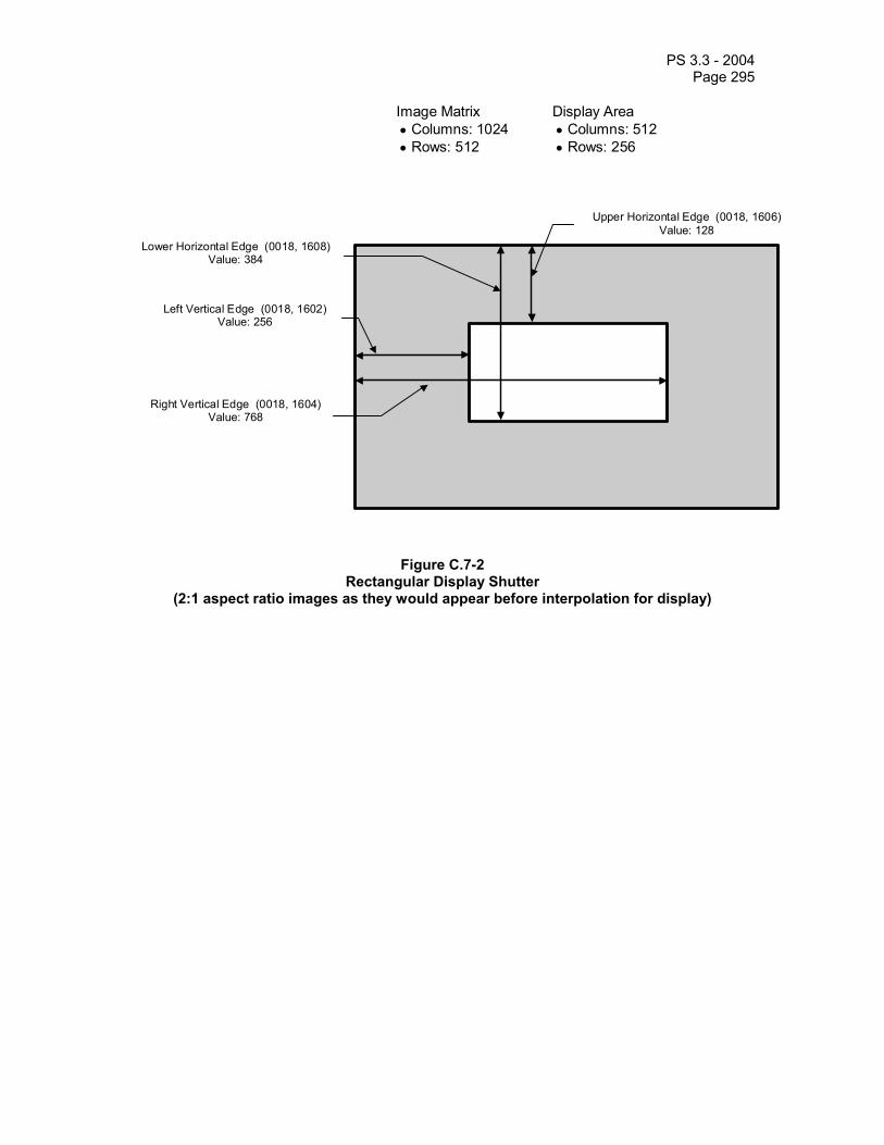
PS 3.3 - 2004 Page 295
Upper Horizontal Edge (0018, 1606) Value: 128
Lower Horizontal Edge (0018, 1608) Value: 384
Right Vertical Edge (0018, 1604) Value: 768
Left Vertical Edge (0018, 1602) Value: 256
Image Matrix Display Area • Columns: 1024 • Columns: 512 • Rows: 512 • Rows: 256
Figure C.7-2 Rectangular Display Shutter
(2:1 aspect ratio images as they would appear before interpolation for display)

PS 3.3 - 2004 Page 296
Center (0018, 1610) Value: 512 \ 512
Radius (0018, 1612)Value: 512
Image Matrix • Columns: 1024 • Rows: 1024
Figure C.7-3 Circular Display Shutter (1:1 aspect ratio image)

PS 3.3 - 2004 Page 297
Center: DICOM element: (0018, 1610) Value: 256 \ 512
Radius: DICOM element (0018, 1612) Value: 512
Image Matrix • Columns: 1024 • Rows: 512
Figure C.7-4 Circular Display Shutter
(2:1 aspect ratio images as they would appear before interpolation for display)
C.7.6.12 Device Module Table C.7-18 describes the Attributes of devices (e.g., catheters, markers, baskets) that are associated with a study and/or image.
Table C.7-18 DEVICE MODULE ATTRIBUTES
Attribute Name Tag Type Attribute Description Device Sequence (0050,0010) 3 Introduces sequence of items describing
devices used that may be visible in the image
>Include ‘Code Sequence Macro’ Table 8.8-1 Baseline Context ID is 8. >Device Length (0050,0014) 3 Length in mm of device. Required as per
Table in Section C.7.6.12.1.1. May be present only if Device Sequence (0050,0010) is present.
>Device Diameter (0050,0016) 3 Unit diameter of device. Required as per Table in Section C.7.6.12.1.1. May be present only if Device Sequence (0050,0010) is present.
>Device Diameter units (0050,0017) 2C Required if Device Diameter (0050,0016) is present. Defined terms:
FR = French GA = Gauge IN = Inch MM = Millimeter
May be present only if Device Sequence
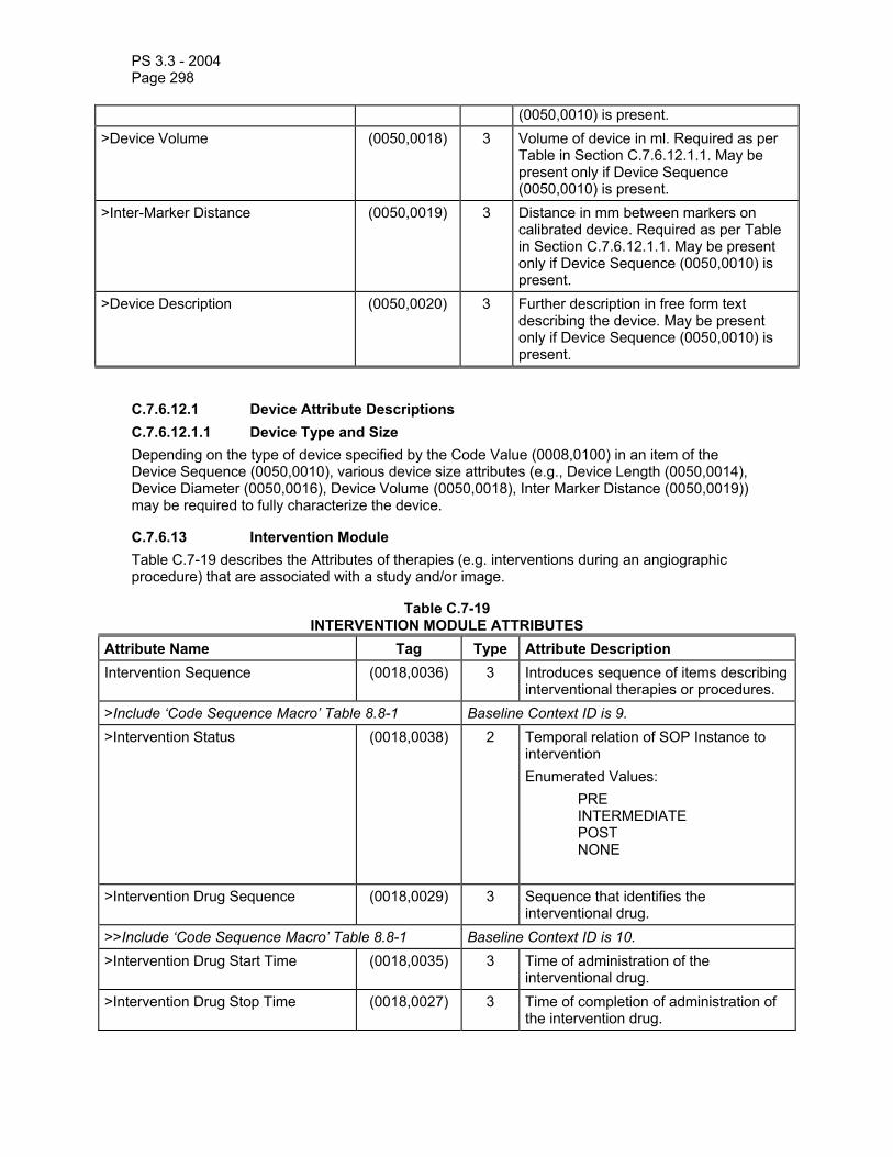
PS 3.3 - 2004 Page 298
(0050,0010) is present. >Device Volume (0050,0018) 3 Volume of device in ml. Required as per
Table in Section C.7.6.12.1.1. May be present only if Device Sequence (0050,0010) is present.
>Inter-Marker Distance (0050,0019) 3 Distance in mm between markers on calibrated device. Required as per Table in Section C.7.6.12.1.1. May be present only if Device Sequence (0050,0010) is present.
>Device Description (0050,0020) 3 Further description in free form text describing the device. May be present only if Device Sequence (0050,0010) is present.
C.7.6.12.1 Device Attribute Descriptions C.7.6.12.1.1 Device Type and Size Depending on the type of device specified by the Code Value (0008,0100) in an item of the Device Sequence (0050,0010), various device size attributes (e.g., Device Length (0050,0014), Device Diameter (0050,0016), Device Volume (0050,0018), Inter Marker Distance (0050,0019)) may be required to fully characterize the device.
C.7.6.13 Intervention Module Table C.7-19 describes the Attributes of therapies (e.g. interventions during an angiographic procedure) that are associated with a study and/or image.
Table C.7-19 INTERVENTION MODULE ATTRIBUTES
Attribute Name Tag Type Attribute Description Intervention Sequence (0018,0036) 3 Introduces sequence of items describing
interventional therapies or procedures. >Include ‘Code Sequence Macro’ Table 8.8-1 Baseline Context ID is 9. >Intervention Status (0018,0038) 2 Temporal relation of SOP Instance to
intervention Enumerated Values: PRE INTERMEDIATE POST NONE
>Intervention Drug Sequence (0018,0029) 3 Sequence that identifies the interventional drug.
>>Include ‘Code Sequence Macro’ Table 8.8-1 Baseline Context ID is 10. >Intervention Drug Start Time (0018,0035) 3 Time of administration of the
interventional drug. >Intervention Drug Stop Time (0018,0027) 3 Time of completion of administration of
the intervention drug.

PS 3.3 - 2004 Page 299
> Administration Route Code Sequence
(0054,0302) 3 Sequence that identifies the Administration Route. This sequence shall contain exactly one item.
>>Include ‘Code Sequence Macro’ Table 8.8-1 Baseline Context ID is 11. >Intervention Description (0018,003A) 3 Further description in free form text
describing the therapy or other intervention.
Note: Therapy Description (0018,0039) was included in this Module in earlier editions, but its use has been retired. See PS 3.3-2003.
C.7.6.14 Acquisition Context Module Table C.7.6.14-1 specifies Attributes for description of the conditions present during data acquisition.
This Module shall not contain descriptions of conditions that replace those that are already described in specific Modules or Attributes that are also contained within the IOD that contains this Module.
Notes: 1. Each item of the Acquisition Context Sequence (0040,0555) contains one item of the Concept Name Code Sequence (0040,A043) and one of the mutually-exclusive Observation-value Attributes: Concept Code Sequence (0040,A168), the pair of Numeric Value (0040,A30A) and Measurement Units Code Sequence (0040,08EA), Date (0040,A121), Time (0040,A122), Person Name (0040,A123) or Text Value (0040,A160).
2. Acquisition Context includes concepts such as: “pre-contrast”, “inspiration”, “valgus stress”, “post-void”, and date and time of contrast administration.
3. If this SOP Instance is a Multi-frame SOP Instance, each item of the Acquisition Context Sequence (0040,0555) may be configured to describe one frame, all frames, or any specifically enumerated subset set of frames of the Multi-frame SOP Instance.
Table C.7.6.14-1 - ACQUISITION CONTEXT MODULE ATTRIBUTES
Attribute Name Tag Type Attribute Description Acquisition Context Sequence
(0040,0555) 2 A sequence of Items that describes the conditions present during the acquisition of the data of the SOP Instance. Zero or more items may be included in this sequence.
>Value Type
((0040,A040) 3 The type of the value encoded in this Item. Defined Terms: TEXT NUMERIC CODE DATE TIME PNAME See Section 10.2.

PS 3.3 - 2004 Page 300
>Concept Name Code Sequence
(0040,A043) 1 A concept that constrains the meaning of (i.e. defines the role of) the Observation Value. The “Name” component of a Name/Value pair. This sequence shall contain exactly one item.
>>Include ‘Code Sequence Macro’ Table 8.8-1 No Baseline Context is defined. >Referenced Frame Numbers
(0040,A136) 1C References one or more frames in a Multi-frame SOP Instance. The first frame shall be denoted as frame number one. Required if this SOP Instance is a Multi-frame SOP Instance and the values in this sequence item do not apply to all frames.
>Numeric Value (0040,A30A) 1C This is the Value component of a Name/Value pair when the Concept implied by Concept Name Code Sequence (0040,A043) is a set of one or more numeric values. Required if the value that Concept Name Code Sequence (0040,A043) requires (implies) is a set of one or more integers or real numbers. Shall not be present otherwise.
>Measurement Units Code Sequence
(0040,08EA) 1C Units of measurement. Only a single Item shall be permitted in this Sequence. Required if Numeric Value (0040,A30A) is sent. Shall not be present otherwise.
>>Include ‘Code Sequence Macro’ Table 8.8-1 Baseline Context ID is 82. >Date (0040,A121) 1C This is the Value component of a Name/Value
pair when the Concept implied by Concept Name Code Sequence (0040,A043) is a date.
Note: The purpose or role of the date value could be specified in Concept Name Code Sequence (0040,A043).
Required if the value that Concept Name Code Sequence (0040,A043) requires (implies) is a date. Shall not be present otherwise.
>Time (0040,A122) 1C This is the Value component of a Name/Value pair when the Concept implied by Concept Name Code Sequence (0040,A043) is a time.
Note: The purpose or role of the time value could be specified in Concept Name Code Sequence (0040,A043).
Required if the value that Concept Name Code Sequence (0040,A043) requires (implies) is a time. Shall not be present otherwise.
>Person Name (0040,A123) 1C This is the Value component of a Name/Value pair when the Concept implied by Concept Name Code Sequence (0040,A043) is a Person Name.
Note: The role of the person could be specified in Concept Name Code Sequence (0040,A043).

PS 3.3 - 2004 Page 301
Required if the value that Concept Name Code Sequence (0040,A043) irequires (implies) is a person name. Shall not be present otherwise.
>Text Value (0040,A160) 1C This is the Value component of a Name/Value pair when the Concept implied by Concept Name Code Sequence (0040,A043) is a Text Observation Value. Required if Date (0040,A121), Time (0040,A122), and Person Name (0040,A123) do not fully describe the concept specified by Concept Name Code Sequence (0040,A043). Shall not be present otherwise.
>Concept Code Sequence
(0040,A168) 1C This is the Value component of a Name/Value pair when the Concept implied by Concept Name Code Sequence (0040,A043) is a Coded Value. This sequence shall contain exactly one item. Required if Date (0040,A121), Time (0040,A122), Person Name (0040,A123), Text Value (0040,A160), and the pair of Numeric Value (0040,A30A) and Measurement Units Code Sequence (0040,08EA) are not present.
>>Include ‘Code Sequence Macro’ Table 8.8-1 No Baseline Context is defined. Acquisition Context Description
(0040,0556) 3 Free-text description of the image-acquisition context.
C.7.6.15 Bitmap Display Shutter Module The Bitmap Display Shutter is a bitmap that defines an arbitrary shape that may be applied on the image for presentation purposes in order to neutralize the display of any of the pixels defined in the bitmap.
The manner in which the display area is neutralized (black-out, gray, or other means) is defined by the Attribute Shutter Presentation Value (0018,1622).
The bitmap is specified as a reference to an instance of the Overlay Plane Module C.9.2. The referenced Overlay is specialized such that:
- Overlay Type (60xx,0040) shall be “G”,
- Overlay Bits Allocated (60xx,0100) shall be 1,
- Overlay Bit Position (60xx,0102) shall be 0 and
- Overlay Origin (60xx,0050) shall be 1\1.
Overlay Rows (60xx,0010) and Overlay Columns (60xx,0011) shall be the same as Rows (0028,0010) and Columns (0028,0011) in the image respectively.
A value of 1 in the Overlay Data (60xx,3000) shall indicate a pixel to which the shutter is applied, i.e. replaced with Shutter Presentation Value (0018,1622).
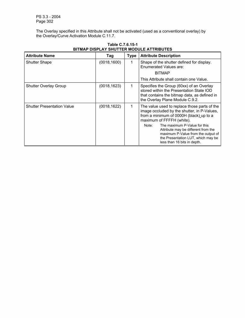
PS 3.3 - 2004 Page 302
The Overlay specified in this Attribute shall not be activated (used as a conventional overlay) by the Overlay/Curve Activation Module C.11.7.
Table C.7.6.15-1 BITMAP DISPLAY SHUTTER MODULE ATTRIBUTES
Attribute Name Tag Type Attribute Description Shutter Shape (0018,1600) 1 Shape of the shutter defined for display.
Enumerated Values are: BITMAP This Attribute shall contain one Value.
Shutter Overlay Group (0018,1623) 1 Specifies the Group (60xx) of an Overlay stored within the Presentation State IOD that contains the bitmap data, as defined in the Overlay Plane Module C.9.2.
Shutter Presentation Value (0018,1622) 1 The value used to replace those parts of the image occluded by the shutter, in P-Values, from a minimum of 0000H (black) up to a maximum of FFFFH (white).
Note: The maximum P-Value for this Attribute may be different from the maximum P-Value from the output of the Presentation LUT, which may be less than 16 bits in depth.

PS 3.3 - 2004 Page 303
C.7.6.16 Multi-frame Functional Groups Module Table C.7.6.16-1 specifies the attributes of the Multi-frame Functional Groups Module. This module is included in SOP instances even if there is only one frame in the instance.
Table C.7.6.16-1 MULTI-FRAME FUNCTIONAL GROUPS MODULE ATTRIBUTES
Attribute Name Tag Type Attribute Description Shared Functional Groups Sequence
(5200,9229) 2 Sequence that contains the Functional Group Macros that are shared for all frames in this SOP Instance and Concatenation.
Note: The contents of this sequence are the same in all SOP Instances that comprise a Concatenation.
Zero or one Item may be included in this sequence. See section C.7.6.16.1.1 for further explanation.
>Include one or more Functional Group Macros that are shared by all frames. The selected Functional Group Macros shall not be present in the Per-frame Functional Groups Sequence (5200,9230).
See section C.7.6.16.1.1 for further explanation. For each IOD that includes this module, a table is defined in which the permitted Functional Group Macros and their usage is specified.
Per-frame Functional Groups Sequence
(5200,9230) 1 Sequence that contains the Functional Group Macros corresponding to each frame of the Multi-frame Image. The first Item corresponds with the first frame, and so on. Each Item shall contain the same set of Functional Group Macros. This Sequence shall contain the same number of Items as the number of frames in the Multi-frame image. See Section C.7.6.16.1.2 for further explanation.
>Include one or more Functional Group Macros. For each IOD that includes this module, a table is defined in which the permitted Functional Group Macros and their usage is specified.
Instance Number (0020,0013) 1 A number that identifies this instance. The value shall be the same for all SOP Instances of a Concatenation, and different for each separate Concatenation and for each SOP Instance not within a Concatenation in a series.
Content Date (0008,0023) 1 The date the data creation was started. Note: For instance, this is the date the
pixel data is created, not the date the data is acquired.
Content Time (0008,0033) 1 The time the data creation was started.

PS 3.3 - 2004 Page 304
Note: For instance, this is the time the pixel data is created, not the time the data is acquired.
Number of Frames (0028,0008) 1 Number of frames in a multi-frame image. See C.7.6.6.1.1 for further explanation.
Concatenation Frame Offset Number
(0020,9228) 1C Offset of the first frame in a multi-frame image of a concatenation. Logical frame numbers in a concatenation can be used across all its SOP instances. This offset can be applied to the implicit frame number to find the logical frame number in a concatenation. Required if Concatenation UID (0020,9161) is present.
Representative Frame Number (0028,6010) 3 The frame number selected for use as a pictorial representation (e.g. icon) of the multi-frame Image.
Concatenation UID (0020,9161) 1C Identifier of all SOP Instances that belong to the same concatenation. Required if a group of multi-frame image SOP Instances within a Series are part of a Concatenation.
In-concatenation Number (0020,9162) 1C Identifier for one SOP Instance belonging to a concatenation. See C.7.6.16.2.2.4 for further specification. Required if Concatenation UID (0020,9161) is present.

PS 3.3 - 2004 Page 305
C.7.6.16.1 Multi-frame Functional Groups Module Attribute Description C.7.6.16.1.1 Functional Group A Functional Group is a set of Attributes that are logically related and may vary together. Functional Groups are defined in Macros. Those Functional Group Macros that apply to all frames are included in the Shared Functional Groups Sequence (5200,9229). Functional Group Macros whose attribute values may vary from frame to frame are included in the Per-frame Functional Groups Sequence (5200,9230).
A single Functional Group Macro shall not be included in both the Shared Functional Groups Sequence (5200,9229)and the Per-frame Functional Groups Sequence (5200,9230).
Notes: 1. In the case of a SOP Instance containing a single frame, some Functional Group Macros may be contained in the Shared Functional Groups Sequence (5200,9229) and others in the one Item of the Per-frame Functional Groups Sequence (5200,9230).
2. Even if there are no Functional Group Macros in the Per-frame Functional Groups Sequence 0008,9230) an empty Item is encoded for every frame.
Private Functional Groups may be defined. The attributes of such a group may be standard or private attributes. A Private Functional Group may not replicate the attributes of a standard Functional Group.
A Private Functional Group can be added to either the Shared Functional Groups Sequence (5200,9229) or the Per-frame Functional Groups Sequence (5200,9230).
C.7.6.16.1.2 Per-frame Functional Groups Sequence The Per-frame Functional Groups Sequence Attribute (5200,9230) consists of a Sequence of Items. Each Item describes the frame of the same rank in the multi-frame pixel data. The first Item describes frame 1, the second Item describes frame 2, etc. Frames are implicitly numbered starting from 1. See Figure C.7.6.16-1.

PS 3.3 - 2004 Page 306
Other attributes
Per-frame Functional Groups Sequence
Shared Functional Groups Sequence
> Functional Group A Macro
> Functional Group B Macro
> Functional Group M Macro
É..
Other attributes
Functional Group Macrosshared for all frames
Item 1 (Frame 1)Sequence of repeating
Functional Group Macros foreach individual frame
Pixel Data
Frame 1
Frame 2
Frame n
É..
> Functional Group C Macro
> Functional Group B Macro
> Functional Group M Macro
É..
Item n (Frame n)
> Functional Group C Macro
> Functional Group B Macro
> Functional Group M Macro
Item 2 (Frame 2)
> Functional Group C Macro
É..
É..
É..
Note: The Functional Group Macros A, B, C, etc. are examples to illustrate the Multi-frame Functional Groups. Theactual Functional Group Sequences are defined elsewhere.
É..
> Functional Group K Macro
Figure C.7.6.16-1 A Graphical Presentation of the Multi-frame Functional Groups structure
C.7.6.16.2 Common Functional Group Macros The following sections contain Functional Group macros common to more than one IOD specification.
Note: The attribute descriptions in the Functional Group Macros are written as if they were applicable to a single frame (i.e., the macro is part of the Per-frame Functional Groups Sequence). If an attribute is applicable to all frames (i.e. the macro is part of the Shared Functional Groups Sequence) the phrase "this frame" in the attribute description shall be interpreted to mean " for all frames".

PS 3.3 - 2004 Page 307
C.7.6.16.2.1 Pixel Measures Macro Table C.7.6.16-2 specifies the attributes of the Pixel Measures Functional Group macro.
Table C.7.6.16-2 PIXEL MEASURES MACRO ATTRIBUTES
Attribute Name Tag Type Attribute Description Pixel Measures Sequence (0028,9110) 1 Identifies the physical characteristics of
the pixels of this frame. Only a single Item shall be permitted in this sequence.
>Pixel Spacing (0028,0030) 1C Physical distance in the patient between the centers of each pixel, specified by a numeric pair - adjacent row spacing (delimiter) adjacent column spacing in mm.
Note: In the case of CT images with an Acquisition Type (0018,9302) of CONSTANT_ANGLE, the pixel spacing is that in a plane normal to the central ray of the diverging X-ray beam as it passes through the data collection center.
Required if Volumetric Properties (0008,9206) is other than DISTORTED or SAMPLED. May be present otherwise.
>Slice Thickness (0018,0050) 1C Nominal reconstructed slice thickness, in mm. See C.7.6.2.1.1 and C.7.6.16.2.3.1 for further explanation. Required if Volumetric Properties (0008,9206) is VOLUME or SAMPLED. May be present otherwise.

PS 3.3 - 2004 Page 308
C.7.6.16.2.2 Frame Content Macro Table C.7.6.16-3 specifies the attributes of the Frame Content Functional Group macro.
This Functional Group Macro may only be part of the Per-frame Functional Groups Sequence (5200,9230) attribute.
Table C.7.6.16-3 FRAME CONTENT MACRO ATTRIBUTES
Attribute Name Tag Type Attribute Description Frame Content Sequence (0020,9111) 1 Identifies general characteristics of this
frame. Only a single Item shall be permitted in this sequence.
>Frame Acquisition Number (0020,9156) 3 A number identifying the single continuous gathering of data over a period of time that resulted in this frame.
>Frame Reference Datetime (0018,9151) 1C The point in time that is most representative of when data was acquired for this frame. See C.7.6.16.2.2.1 and C.7.6.16.2.2.2 for further explanation.
Note: The synchronization of this time with an external clock is specified in the synchronization Module in Acquisition Time synchronized (0018,1800).
Required if Frame Type (0008,9007) Value 1 of this frame is ORIGINAL. May be present otherwise.
>Frame Acquisition Datetime (0018,9074) 1C The date and time that the acquisition of data that resulted in this frame started. See C.7.6.16.2.2.1 for further explanation. Required if Frame Type (0008,9007) Value 1 of this frame is ORIGINAL. May be present otherwise.
>Frame Acquisition Duration (0018,9220) 1C The actual amount of time [in milliseconds] that was used to acquire data for this frame. See C.7.6.16.2.2.1 and C.7.6.16.2.2.3 for further explanation.Required if Frame Type (0008,9007) Value 1 of this frame is ORIGINAL. May be present otherwise.
>Cardiac Cycle Position (0018,9236) 3 Description of the position in the cardiac cycle that is most representative of this frame. Defined Terms: END_SYSTOLE END_DIASTOLE UNDETERMINED
>Respiratory Cycle Position (0018,9214) 3 Description of the position in the respiratory cycle that is most

PS 3.3 - 2004 Page 309
representative of this frame. Defined Terms: START _RESPIR END_RESPIR UNDETERMINED
>Dimension Index Values (0020,9157) 1C Contains the values of the indices defined in the Dimension Index Sequence (0020,9222) for this multi-frame header frame. The number of values is equal to the number of Items of the Dimension Index Sequence and shall be applied in the same order. See section C.7.6.17.1 for a description. Required if the value of the Dimension Index Sequence (0020,9222) contains Items.
>Temporal Position Index (0020,9128) 3 Ordinal number (starting from 1) of the frame in the set of frames with different temporal positions.
>Stack ID (0020,9056) 3 Identification of a group of frames, with different positions and/or orientations that belong together, within a dimension organization. See C.7.6.16.2.2.4 for further explanation
>In-Stack Position Number (0020,9057) 1C The ordinal number of a frame in a group of frames, with the same Stack ID Required if Stack ID (0020,9056) is present. See section C.7.6.16.2.2.4 for further explanation.
>Frame Comments (0020,9158) 3 User-defined comments about the frame.
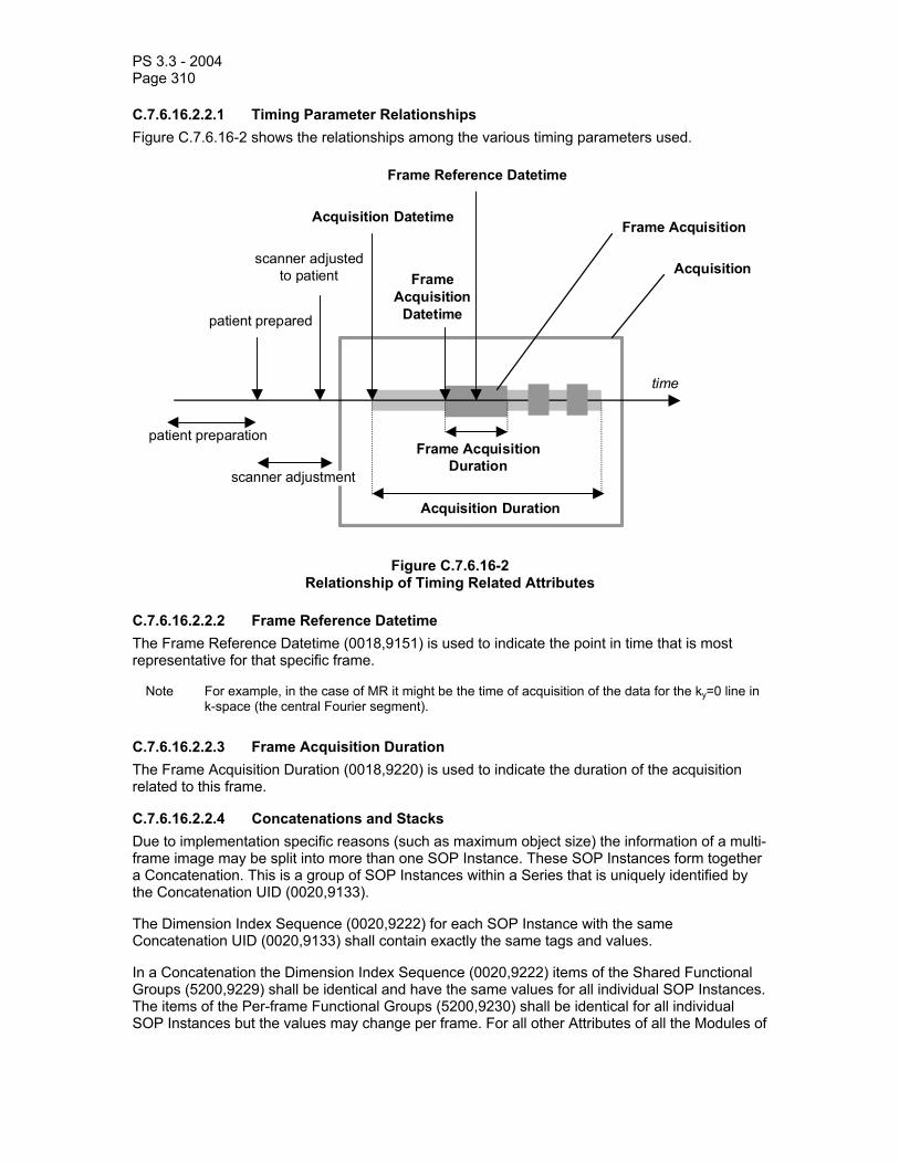
PS 3.3 - 2004 Page 310
C.7.6.16.2.2.1 Timing Parameter Relationships Figure C.7.6.16-2 shows the relationships among the various timing parameters used.
time
patient prepared
patient preparation
scanner adjustedto patient
scanner adjustment
Acquisition Datetime
Acquisition Duration
Frame AcquisitionDuration
Frame Reference Datetime
FrameAcquisition
Datetime
Frame Acquisition
Acquisition
Figure C.7.6.16-2 Relationship of Timing Related Attributes
C.7.6.16.2.2.2 Frame Reference Datetime The Frame Reference Datetime (0018,9151) is used to indicate the point in time that is most representative for that specific frame.
Note For example, in the case of MR it might be the time of acquisition of the data for the ky=0 line in k-space (the central Fourier segment).
C.7.6.16.2.2.3 Frame Acquisition Duration The Frame Acquisition Duration (0018,9220) is used to indicate the duration of the acquisition related to this frame.
C.7.6.16.2.2.4 Concatenations and Stacks Due to implementation specific reasons (such as maximum object size) the information of a multi-frame image may be split into more than one SOP Instance. These SOP Instances form together a Concatenation. This is a group of SOP Instances within a Series that is uniquely identified by the Concatenation UID (0020,9133).
The Dimension Index Sequence (0020,9222) for each SOP Instance with the same Concatenation UID (0020,9133) shall contain exactly the same tags and values.
In a Concatenation the Dimension Index Sequence (0020,9222) items of the Shared Functional Groups (5200,9229) shall be identical and have the same values for all individual SOP Instances. The items of the Per-frame Functional Groups (5200,9230) shall be identical for all individual SOP Instances but the values may change per frame. For all other Attributes of all the Modules of

PS 3.3 - 2004 Page 311
the IOD, the same Attributes shall be present and the values shall be identical, with the exception of the following Attributes:
• Number of Frames (0028,0008) • Concatenation Frame Offset Number (0020,9228)
Note: The intent of Concatenations is to split what might have been encoded in a single SOP Instance
into smaller fragments for more convenient storage or transmission. All the multiple SOP Instances of a Concatenation should be able to be assembled into a valid single SOP Instance. Hence it is not permitted to change such Attributes as Photometric Interpretation (0028,0004), Rows (0028,0010), Columns (0028,0011), etc.

PS 3.3 - 2004 Page 312
Stacks describe application-specific groups of frames that have a geometric relationship. Stacks have a Stack ID (0020,9056) that contains a descriptive name that identifies the stack. A Stack ID (0020,9056) may be re-used in another SOP Instance even outside a concatenation. The value of Stack ID (0020,9056) is unique within the scope of a particular Dimension Organization UID (0020,9164) if present, otherwise it is unique within in the scope of a particular Concatenation UID (0020,9133). See Figure C7.6.16-3 for an example.
Frames:
SOP Instance
Concatenation
Series
• In-Concatenation Number (0020,9162) – shall be unique within Concatenation [if part of a Concatenation]
• Instance Number (0020,0013) –shall be the same for all SOP Instances of a Concatenation and different for each separate Concatenation inside a series.
• Concatenation Frame Offset Number (0020,9228) shall be unique within Concatenation
• Implicit Frame Number – is unique within SOP Instance; (not an attribute)
• In-Stack Number (0020,9057) – shall be unique within Stack ID (0020,9056)
Identifying Attributes and Scope
• Series Number (0020,0011)
Stacks: • Stack ID (0020,9056) – shall be unique within Concatenation; must be unique within Dimension Organization if the Stack ID (0020,9056) tag is referenced by a Dimension Index Pointer (0020,9165)
SOP Instance
Figure C.7.6.16-3 Identifying attributes for Concatenation, SOP Instances, Frames and Stacks
Each frame in a stack has an In-Stack Position Number (0020,9057) that is the ordinal number (starting from 1) of the frame within the set of frames with the same Stack ID (0020,9056), see Figure C.7.6.16-4 for an example.

PS 3.3 - 2004 Page 313
Stack ID3
Frame Number 1 - 5
Frame Number 19 -23
Frame Number 27 - 31
54
32
1In-Stack Position
Stack ID2
Stack ID1
54
32
1In-Stack Position
54
32
1In-Stack Position
Figure C.7.6.16-4 Example of multiple stacks
In order to allow interoperable operations on stacks, 2 different frames with the same Stack ID (0020,9056) can only have the same In-Stack Position Number (0020,9057) if they have the same values for the following attributes:
1. Dimension Organization UID (0020,9164) or if absent Concatenation UID (0020,9133) to qualify the Stack ID
2. Image Position (Patient) (0020,0032) 3. Image Orientation (Patient) (0020,0037) 4. Rows (0028,0010) ∗ Pixel Spacing (0028,0030) (= field of view in the row direction) 5. Columns (0028,0011) ∗ Pixel Spacing (0028,0030) (= field of view in the column direction) 6. Slice Thickness (0018,0050)

PS 3.3 - 2004 Page 314
C.7.6.16.2.3 Plane Position Macro Table C.7.6.16-4 specifies the attributes of the Plane Position Functional Group macro.
Table C.7.6.16-4 PLANE POSITION MACRO ATTRIBUTES
Attribute Name Tag Type Attribute Description Plane Position Sequence (0020,9113) 1 Identifies the position of the plane of this
frame. Only a single Item shall be permitted in this sequence.
>Image Position (Patient) (0020,0032) 1C The x, y, and z coordinates of the upper left hand corner (center of the first voxel transmitted) of the frame, in mm. See C.7.6.2.1.1 and C.7.6.16.2.3.1 for further explanation.
Note: In the case of CT images with an Acquisition Type (0018,9302) of CONSTANT_ANGLE the image plane is defined to pass through the data collection center and be normal to the central ray of the diverging X-ray beam.
Required if Frame Type (0008,9007) Value 1 of this frame is ORIGINAL and Volumetric Properties (0008,9206) of this frame is other than DISTORTED, may be present otherwise.
C.7.6.16.2.3.1 Position and Orientation for SAMPLED Frames In the case of Volumetric Properties (0008,9206) having a value of SAMPLED, the Image Position (0020,0032), Image Orientation (0020,0037) and Slice Thickness (0018,0050) shall represent the volume from which the frame was derived based on the orientation of the sampling performed.
Note: For example in the case of MAX_IP: The Image Orientation shall be the direction of the ray used for projection of the center of the
plane. The image position shall contain the x, y, and z coordinates of the intersection of the mid-plane
of the sampled volume with the ray used to project the upper left hand corner of the frame. The Slice Thickness shall contain the distance that the ray used for projection of the center of
the plane traveled through the volume.
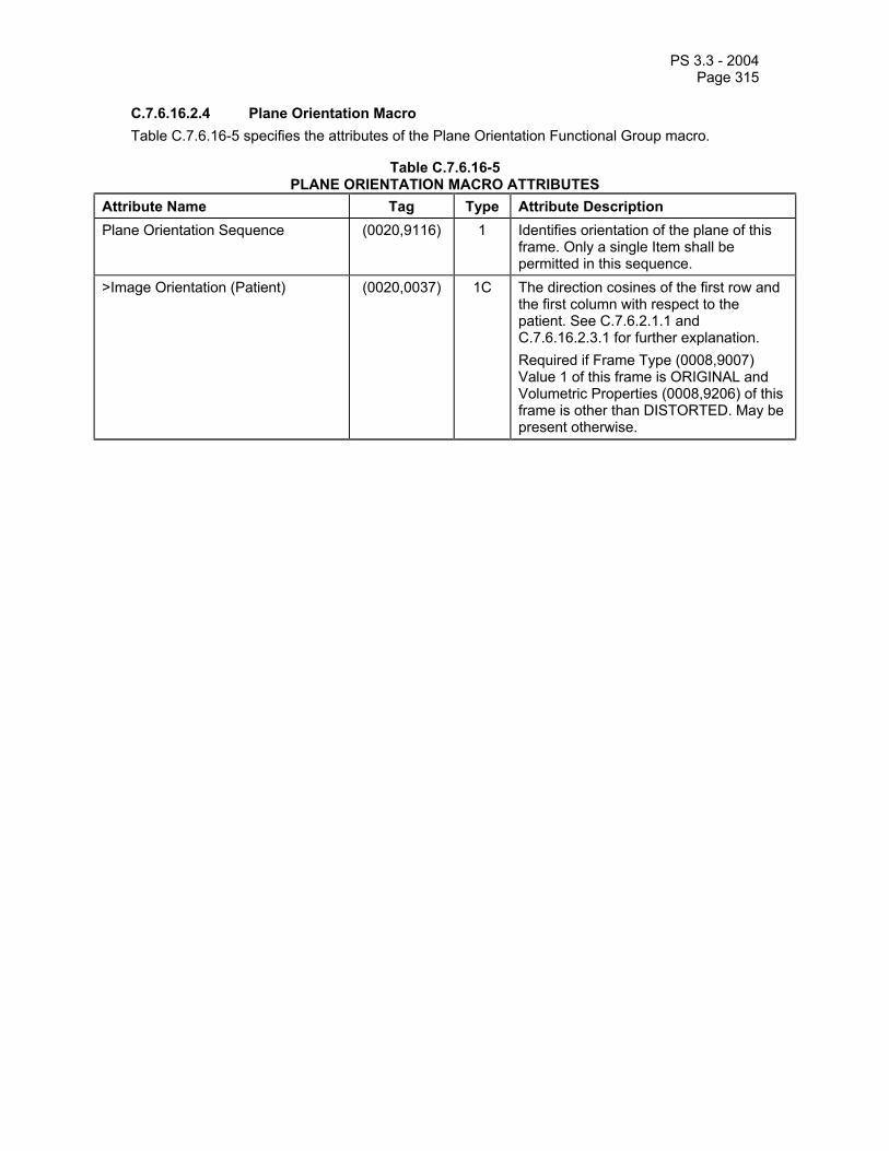
PS 3.3 - 2004 Page 315
C.7.6.16.2.4 Plane Orientation Macro Table C.7.6.16-5 specifies the attributes of the Plane Orientation Functional Group macro.
Table C.7.6.16-5 PLANE ORIENTATION MACRO ATTRIBUTES
Attribute Name Tag Type Attribute Description Plane Orientation Sequence (0020,9116) 1 Identifies orientation of the plane of this
frame. Only a single Item shall be permitted in this sequence.
>Image Orientation (Patient) (0020,0037) 1C The direction cosines of the first row and the first column with respect to the patient. See C.7.6.2.1.1 and C.7.6.16.2.3.1 for further explanation. Required if Frame Type (0008,9007) Value 1 of this frame is ORIGINAL and Volumetric Properties (0008,9206) of this frame is other than DISTORTED. May be present otherwise.

PS 3.3 - 2004 Page 316
C.7.6.16.2.5 Referenced Image Macro Table C.7.6.16-6 specifies the attributes of the Referenced Image Functional Group macro.
Table C.7.6.16-6 REFERENCED IMAGE MACRO ATTRIBUTES
Attribute Name Tag Type Attribute Description Referenced Image Sequence (0008,1140) 2 A sequence that provides reference to a
set of SOP Class/Instance pairs identifying images or other composite SOP Instances used to plan the acquisition or significant related images. See Section C.7.6.16.2.5.1 for further explanation. Zero or more Items may be included in this Sequence.
>Referenced SOP Class UID (0008,1150) 1 Uniquely identifies the referenced SOP Class.
>Referenced SOP Instance UID (0008,1155) 1 Uniquely identifies the referenced SOP Instance.
>Referenced Frame Number (0008,1160) 1C References one or more image frames of a Multi-frame Image SOP Instance, identifying which frames are significantly related to this image. Required if reference is provided to a Multi-frame SOP Instance and not all frames are referenced.
>Purpose of Reference Code Sequence
(0040,A170) 1 Describes the purpose for which the reference is made. Only a single Item shall be permitted in this sequence. See C.7.6.16.2.5.1 for further explanation.
>>Include ‘Code Sequence Macro’ Table 8.8-1 Defined Context ID is 7201.
C.7.6.16.2.5.1 Use of Referenced Image Macro Referenced Image Sequence (0008,1140) shall be used to provide a reference to a set of SOP Class/Instance pairs identifying other data objects used to plan the acquisition of this image where the images shall share the same Frame of Reference UID (0020,0052). For each Item that contains such a reference, the value of the Purpose of Reference Code Sequence (0040,A170) shall be (”121311”, DCM, ”Localizer"). Applications can use the Referenced Image Sequence (0008,1140) in combination with data in Plane Position and Plane Orientation Macros to provide projections of the position of an image with respect to the referenced image.
The Referenced Image Sequence (0008,1140) may also be present when references to other images (or frames within other images) are required for other reasons, as specified by Purpose of Reference Code Sequence (0040,A170).
Note: An Image may contain references to itself (e.g. to other frames within itself).

PS 3.3 - 2004 Page 317
C.7.6.16.2.6 Derivation Image Macro Table C.7.6.16-7 specifies the attributes of the Derivation Image Functional Group macro.
Table C.7.6.16-7 DERIVATION IMAGE MACRO ATTRIBUTES
Attribute Name Tag Type Attribute Description Derivation Image Sequence (0008,9124) 2 A sequence that that provides reference
to the set of SOP Class/Instance pairs of the Images or other composite SOP Instances which were used to derive this frame. Zero or more Items may be included in this Sequence.
>Derivation Description (0008,2111) 3 A text description of how this frame data was derived. See C.7.6.1.1.3 for further explanation.
>Derivation Code Sequence (0008,9215) 1 A coded description of how this frame was derived. See C.7.6.1.1.3 for further explanation.
>>Include ‘Code Sequence Macro’ Table 8.8-1 Defined Context ID is 7203. >Source Image Sequence (0008,2112) 2 A Sequence which identifies the set of
Image or other SOP Class/Instance pairs of the Instances which were used to derive this frame. Zero or more Items may be included in this Sequence. See C.7.6.1.1.4 for further explanation.
>>Referenced SOP Class UID (0008,1150) 1 Uniquely identifies the referenced SOP Class.
>>Referenced SOP Instance UID (0008,1155) 1 Uniquely identifies the referenced SOP Instance.
>>Referenced Frame Number (0008,1160) 1C References one or more image frames of a Multi-frame SOP Instance, identifying which frames are significantly related to this image. Required if referenced to another Multi-frame image SOP Instance and not all frames are included.
>>Purpose of Reference Code Sequence
(0040,A170) 1 Describes the purpose for which the reference is made, that is what role the source image or frame played in the derivation of this image or frame. Only a single Item shall be permitted in this sequence.
>>>Include ‘Code Sequence Macro’ Table 8.8-1 Defined Context ID is 7202.
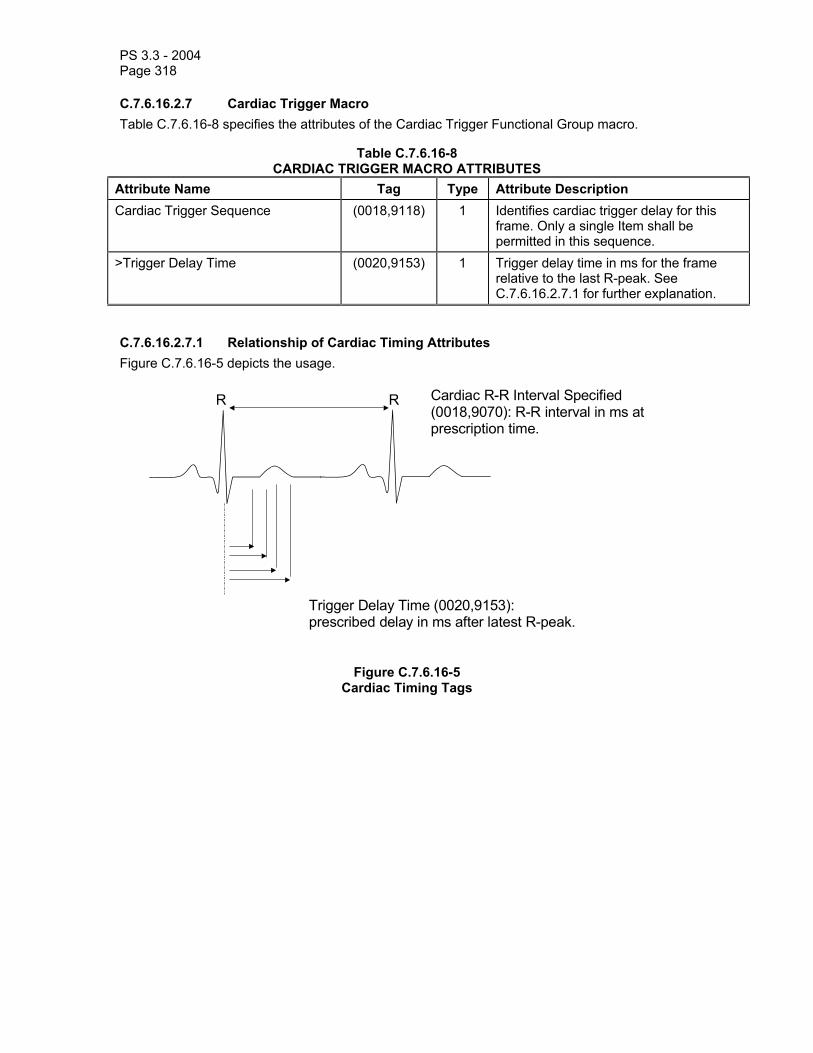
PS 3.3 - 2004 Page 318
C.7.6.16.2.7 Cardiac Trigger Macro Table C.7.6.16-8 specifies the attributes of the Cardiac Trigger Functional Group macro.
Table C.7.6.16-8 CARDIAC TRIGGER MACRO ATTRIBUTES
Attribute Name Tag Type Attribute Description Cardiac Trigger Sequence (0018,9118) 1 Identifies cardiac trigger delay for this
frame. Only a single Item shall be permitted in this sequence.
>Trigger Delay Time (0020,9153) 1 Trigger delay time in ms for the frame relative to the last R-peak. See C.7.6.16.2.7.1 for further explanation.
C.7.6.16.2.7.1 Relationship of Cardiac Timing Attributes Figure C.7.6.16-5 depicts the usage.
Cardiac R-R Interval Specified(0018,9070): R-R interval in ms atprescription time.
RR
Trigger Delay Time (0020,9153):prescribed delay in ms after latest R-peak.
Figure C.7.6.16-5 Cardiac Timing Tags

PS 3.3 - 2004 Page 319
C.7.6.16.2.8 Frame Anatomy Macro Table C.7.6.16-9 specifies the attributes of the Frame Anatomy Functional Group macro.
Table C.7.6.16-9 FRAME ANATOMY MACRO ATTRIBUTES
Attribute Name Tag Type Attribute Description Frame Anatomy Sequence (0020,9071) 1 Identifies anatomic characteristics of this
frame. Only a single Item shall be permitted in this sequence.
>Frame Laterality (0020,9072) 1 Laterality of (possibly paired) body parts (as described in Anatomic Region Sequence (0008,2218)) examined. Enumerated Values:
R = right L = left U = unpaired B = both left and right
Note: This Attribute is mandatory, in order to ensure that frames may be positioned correctly relative to one another for display.
Shall be consistent with any laterality information contained in Primary Anatomic Structure Modifier Sequence (0008,2230), if present.
>Include 'General Anatomy Required Macro' Table 10-6 Defined Context ID for the Anatomic Region Sequence is 4030. Defined Context ID for Anatomic Region Sequence (0008,2218) and Primary Anatomic Structure Modifier Sequence (0008,2230) is 2.

PS 3.3 - 2004 Page 320
C.7.6.16.2.9 Pixel Value Transformation Macro Table C.7.6.16-10 specifies the attributes of the Pixel Value Transformation Functional Group macro.
Note: This Macro is equivalent with the Modality LUT transformation in non Multi-frame IODs.
Table C.7.6.16-10 PIXEL VALUE TRANSFORMATION MACRO ATTRIBUTES
Attribute Name Tag Type Attribute Description Pixel Value Transformation Sequence
(0028,9145) 1 Contains the attributes involved in the transformation of stored pixel values. Only a single Item shall be permitted in this sequence.
>Rescale Intercept (0028,1052) 1 The value b in relationship between stored values (SV) and the output units. Output units = m*SV + b.
>Rescale Slope (0028,1053) 1 m in the equation specified by Rescale Intercept (0028,1052).
>Rescale Type (0028,1054) 1 Specifies the output units of Rescale Slope (0028,1053) and Rescale Intercept (0028,1052). See C.11.1.1.2 for further explanation. Enumerated Value:
US = Unspecified if Modality (0008,0060) equals MR.

PS 3.3 - 2004 Page 321
C.7.6.16.2.10 Frame VOI LUT Macro Table C.7.6.16-11 specifies the attributes of the Frame VOI LUT Functional Group macro.
Table C.7.6.16-11 FRAME VOI LUT MACRO ATTRIBUTES
Attribute Name Tag Type Attribute Description Frame VOI LUT Sequence (0028,9132) 2 Window Center and Width values applied
to the frame. Zero or one item may be included in this sequence.
>Window Center (0028,1050) 1 Window Center for display. See C.11.2.1.2 for further explanation.
>Window Width (0028,1051) 1 Window Width for display. See C.11.2.1.2 for further explanation.
>Window Center & Width Explanation
(0028,1055) 3 Explanation of the Window Center and Width. Defined Terms for CT:
BRAIN SOFT_TISSUE LUNG BONE
C.7.6.16.2.11 Real World Value Mapping Macro Table C.7.6.16-12 specifies the attributes of the Real World Value Mapping Functional Group macro.
Table C.7.6.16-12 REAL WORLD VALUE MAPPING MACRO ATTRIBUTES
Attribute Name Tag Type Attribute Description Real World Value Mapping Sequence
(0040,9096) 1 The mapping of stored values to associated real world values. One or more Items may be included in this sequence.
>Real World Value First Value Mapped
(0040,9216) 1 Specifies the first stored value mapped for the Real Word Value Intercept (0040, 9224) and Real World Value Slope (0040,9225) or Real World Value LUT (0040,9212) of this Item. See C.7.6.16.2.11.1 for further explanation.
>Real World Value Last Value Mapped
(0040,9211) 1 Specifies the last stored value mapped for the Real Word Value Intercept (0040, 9224) and Real World Value Slope (0040,9225) or Real World Value LUT (0040,9212) of this Item. See C.7.6.16.2.11.1 for further explanation.
>Real World Value Intercept (0040,9224) 1C The Intercept value in relationship between stored values (SV) and the real world values.
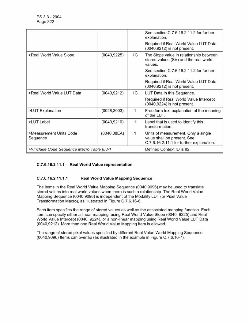
PS 3.3 - 2004 Page 322
See section C.7.6.16.2.11.2 for further explanation. Required if Real World Value LUT Data (0040,9212) is not present.
>Real World Value Slope (0040,9225) 1C The Slope value in relationship between stored values (SV) and the real world values. See section C.7.6.16.2.11.2 for further explanation. Required if Real World Value LUT Data (0040,9212) is not present.
>Real World Value LUT Data (0040,9212) 1C LUT Data in this Sequence. Required if Real World Value Intercept (0040,9224) is not present.
>LUT Explanation (0028,3003) 1 Free form text explanation of the meaning of the LUT.
>LUT Label (0040,9210) 1 Label that is used to identify this transformation.
>Measurement Units Code Sequence
(0040,08EA) 1 Units of measurement. Only a single value shall be present. See C.7.6.16.2.11.1 for further explanation.
>>Include Code Sequence Macro Table 8.8-1 Defined Context ID is 82
C.7.6.16.2.11.1 Real World Value representation
C.7.6.16.2.11.1.1 Real World Value Mapping Sequence
The items in the Real World Value Mapping Sequence (0040,9096) may be used to translate stored values into real world values when there is such a relationship. The Real World Value Mapping Sequence (0040,9096) is independent of the Modality LUT (or Pixel Value Transformation Macro), as illustrated in Figure C.7.6.16-6.
Each item specifies the range of stored values as well as the associated mapping function. Each item can specify either a linear mapping, using Real World Value Slope (0040, 9225) and Real World Value Intercept (0040, 9224), or a non-linear mapping using Real World Value LUT Data (0040,9212). More than one Real World Value Mapping Item is allowed.
The range of stored pixel values specified by different Real Value World Mapping Sequence (0040,9096) Items can overlap (as illustrated in the example in Figure C.7.6.16-7).
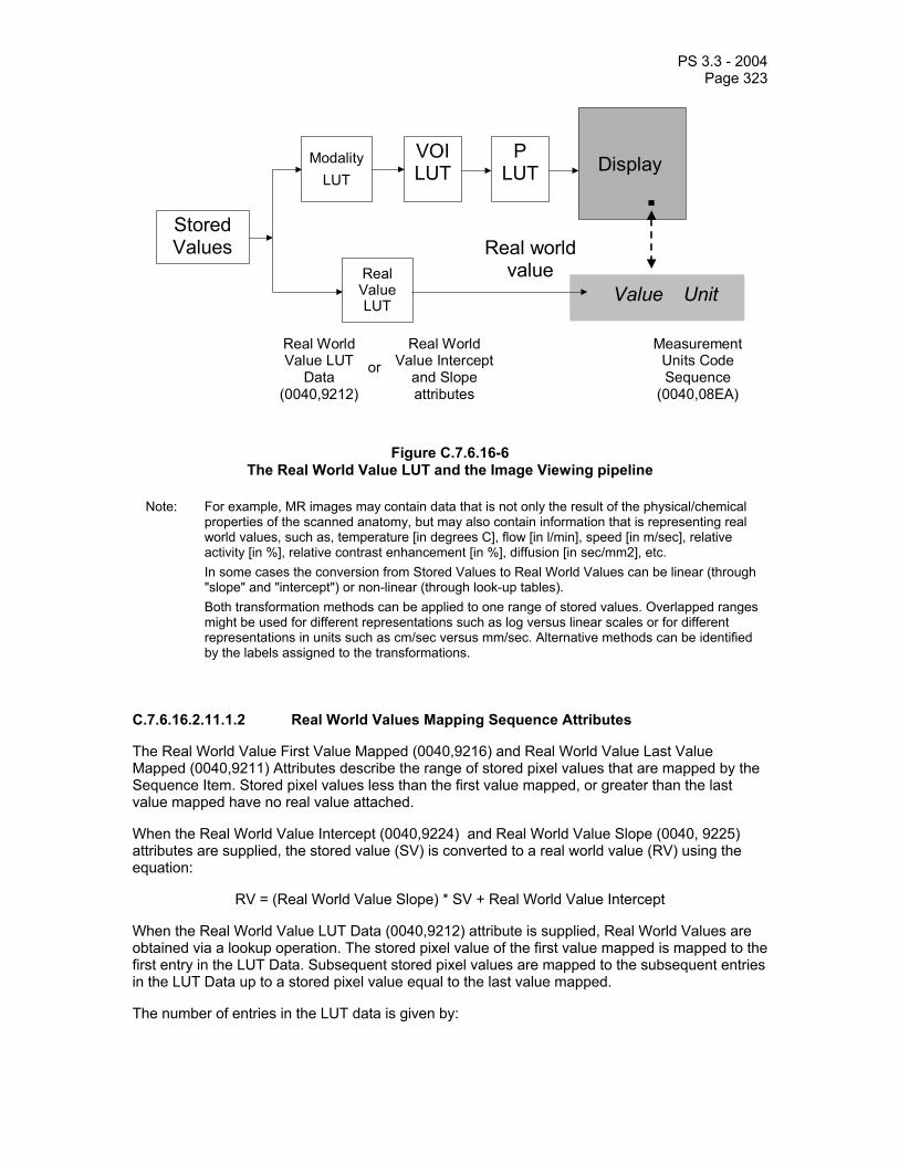
PS 3.3 - 2004 Page 323
Value Unit
Stored Values
Real Value LUT
VOILUT
P LUT Display
Real world value
ModalityLUT
Measurement Units Code Sequence
(0040,08EA)
Real World Value LUT
Data (0040,9212)
Real World Value Intercept
and Slope attributes
or
Figure C.7.6.16-6 The Real World Value LUT and the Image Viewing pipeline
Note: For example, MR images may contain data that is not only the result of the physical/chemical properties of the scanned anatomy, but may also contain information that is representing real world values, such as, temperature [in degrees C], flow [in l/min], speed [in m/sec], relative activity [in %], relative contrast enhancement [in %], diffusion [in sec/mm2], etc.
In some cases the conversion from Stored Values to Real World Values can be linear (through "slope" and "intercept") or non-linear (through look-up tables).
Both transformation methods can be applied to one range of stored values. Overlapped ranges might be used for different representations such as log versus linear scales or for different representations in units such as cm/sec versus mm/sec. Alternative methods can be identified by the labels assigned to the transformations.
C.7.6.16.2.11.1.2 Real World Values Mapping Sequence Attributes
The Real World Value First Value Mapped (0040,9216) and Real World Value Last Value Mapped (0040,9211) Attributes describe the range of stored pixel values that are mapped by the Sequence Item. Stored pixel values less than the first value mapped, or greater than the last value mapped have no real value attached.
When the Real World Value Intercept (0040,9224) and Real World Value Slope (0040, 9225) attributes are supplied, the stored value (SV) is converted to a real world value (RV) using the equation:
RV = (Real World Value Slope) * SV + Real World Value Intercept
When the Real World Value LUT Data (0040,9212) attribute is supplied, Real World Values are obtained via a lookup operation. The stored pixel value of the first value mapped is mapped to the first entry in the LUT Data. Subsequent stored pixel values are mapped to the subsequent entries in the LUT Data up to a stored pixel value equal to the last value mapped.
The number of entries in the LUT data is given by:
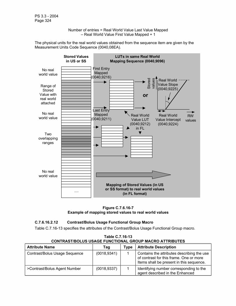
PS 3.3 - 2004 Page 324
Number of entries = Real World Value Last Value Mapped – Real World Value First Value Mapped + 1
The physical units for the real world values obtained from the sequence item are given by the Measurement Units Code Sequence (0040,08EA).
....
Stored Values in US or SS
LUTs in same Real World Mapping Sequence (0040,9096)
First Entry Mapped
(0040,9216)
Range of Stored
Value with real world attached
Two overlapping
ranges
Real World Value LUT
(0040,9212)in FL
Mapping of Stored Values (in US or SS format) to real world values
(in FL format)
No real world value
No real world value
No real world value
Last Entry Mapped
(0040,9211)
Real World Value Slope (0040,9225)
Real World Value Intercept
(0040,9224)
RW values
Sto
red
valu
es
or
Figure C.7.6.16-7 Example of mapping stored values to real world values
C.7.6.16.2.12 Contrast/Bolus Usage Functional Group Macro Table C.7.16-13 specifies the attributes of the Contrast/Bolus Usage Functional Group macro.
Table C.7.16-13 CONTRAST/BOLUS USAGE FUNCTIONAL GROUP MACRO ATTRIBUTES
Attribute Name Tag Type Attribute Description Contrast/Bolus Usage Sequence (0018,9341) 1 Contains the attributes describing the use
of contrast for this frame. One or more Items shall be present in this sequence.
>Contrast/Bolus Agent Number (0018,9337) 1 Identifying number corresponding to the agent described in the Enhanced

PS 3.3 - 2004 Page 325
Contrast/Bolus Module. >Contrast/Bolus Agent Administered (0018,9342) 1 The administration of the selected agent
had begun by the time this frame was acquired. Defined Terms: YES NO
>Contrast/Bolus Agent Detected (0018,9343) 2 The selected agent was detected in the frame. Defined Terms: YES NO May only be zero length if the acquisition device is not capable of detecting the presence of this contrast agent in the frame.
>Contrast/Bolus Agent Phase (0018,9344) 2C Nominal phase of intravenous contrast administration. Defined terms: PRE_CONTRAST POST_CONTRAST IMMEDIATE DYNAMIC STEADY_STATE DELAYED ARTERIAL CAPILLARY VENOUS PORTAL_VENOUS Required if Contrast/Bolus Administration Route Sequence (0018,0014) for the Contrast/Bolus Agent Number (0018,9337) defined in the Contrast/Bolus Agent Sequence (0018,0012) is (SNM3, G-D101, “Intravenous route”).

PS 3.3 - 2004 Page 326
C.7.6.17 Multi-frame Dimension Module The Multi-frame Dimension Module contains a sequence with items pointing to attributes defining a set of dimensions that are usually known prior to the acquisition commencing. It is up to the generating applications to decide what attributes are important to describe the multi-frame dimensions.
The application that generates the Concatenation or SOP Instances may use the order of Dimension Index Pointers (0020,9165) in the Dimension Index Sequence (0020,9222) to guide the receiving application in determining the order of the presentation of image frames. The first index has the highest ranking, the next index has a lower ranking, etc. Frames with higher values for the dimension with the highest ranking would only be presented after all frames that have values for Dimension Index Pointers (0020,9165) of the lower rankings have been presented.
If the set of Dimension Index Pointers does not provide an attribute set whose values are unique for each frame then the order for the frames with the same value set will be incompletely specified. The receiving application could use the logical frame number to resolve this ambiguity. If the attribute set contains more dimensions than are needed to specify a unique ordering, the lower order ranking attribute(s) will have no effect on the ordering.
Note: For example if there were the following indices in the following order: - Stack ID (1-3) - In-stack Position Number (1-2 for Stack ID 1, 1-4 for Stack ID 2, 1-3 for Stack ID 3) - Effective Echo Time (1-2), i.e. every slice has been scanned with 2 different effective echo's Then the frames could be presented in the following order: (Stack ID, In-stack Position, Effective Echo Time) (1,1,1), (1,1,2), (1,2,1), (1,2,2), (2,1,1), (2,1,2), (2,2,1), (2,2,2), (2,3,1), (2,3,2), (2,4,1), (2,4,2) (3,1,1), (3,1,2), (3,2,1), (3,2,2), (3,3,1), (3,3,2) The actual order of the frames in the object is up to the generating application. If the effective echo time was not included in the Dimension Index Pointers in the above
example then the order of sorting for the frames with the same indices will be undefined – in this case there would be 2 frames with the index set (Stack ID, In-stack Position) = (1,1) and the order of these frames is not specified.
If there were another attribute appended to the Dimension Index Pointers, for example TR, then the TR index would not be used in determining the order of the frames. So the Index Frame Pointers would contain (Stack ID, In-stack Position, Effective Echo Time, TR) but the TR index would be irrelevant for frame ordering purposes.
Table C.7.6.17-1 specifies the attributes of the Multi-frame Dimension Module.
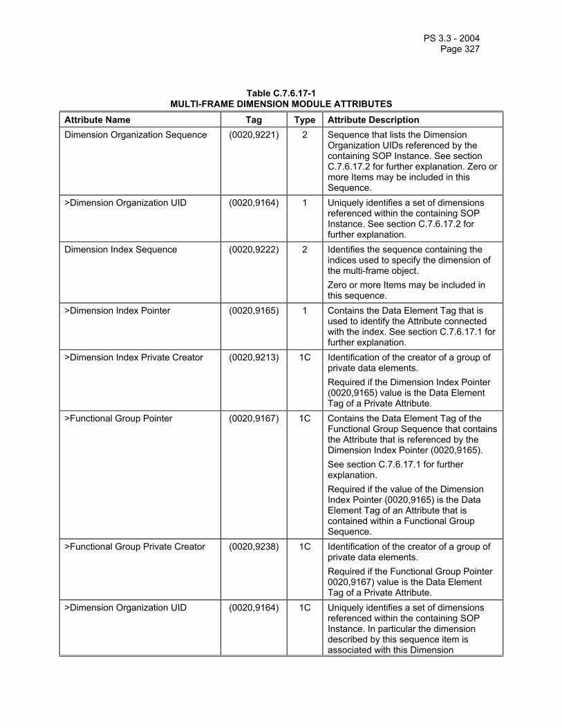
PS 3.3 - 2004 Page 327
Table C.7.6.17-1 MULTI-FRAME DIMENSION MODULE ATTRIBUTES
Attribute Name Tag Type Attribute Description Dimension Organization Sequence (0020,9221) 2 Sequence that lists the Dimension
Organization UIDs referenced by the containing SOP Instance. See section C.7.6.17.2 for further explanation. Zero or more Items may be included in this Sequence.
>Dimension Organization UID (0020,9164) 1 Uniquely identifies a set of dimensions referenced within the containing SOP Instance. See section C.7.6.17.2 for further explanation.
Dimension Index Sequence (0020,9222) 2 Identifies the sequence containing the indices used to specify the dimension of the multi-frame object. Zero or more Items may be included in this sequence.
>Dimension Index Pointer (0020,9165) 1 Contains the Data Element Tag that is used to identify the Attribute connected with the index. See section C.7.6.17.1 for further explanation.
>Dimension Index Private Creator (0020,9213) 1C Identification of the creator of a group of private data elements. Required if the Dimension Index Pointer (0020,9165) value is the Data Element Tag of a Private Attribute.
>Functional Group Pointer (0020,9167) 1C Contains the Data Element Tag of the Functional Group Sequence that contains the Attribute that is referenced by the Dimension Index Pointer (0020,9165). See section C.7.6.17.1 for further explanation. Required if the value of the Dimension Index Pointer (0020,9165) is the Data Element Tag of an Attribute that is contained within a Functional Group Sequence.
>Functional Group Private Creator (0020,9238) 1C Identification of the creator of a group of private data elements. Required if the Functional Group Pointer 0020,9167) value is the Data Element Tag of a Private Attribute.
>Dimension Organization UID (0020,9164) 1C Uniquely identifies a set of dimensions referenced within the containing SOP Instance. In particular the dimension described by this sequence item is associated with this Dimension

PS 3.3 - 2004 Page 328
Organization UID. See section C.7.6.17.2 for further explanation. Required if the value of the Dimension Index Sequence (0020,9222) contains Items
C.7.6.17.1 Dimension Indices With the Dimension Index Sequence (0020,9222) , Data Element Tags are specified that identify the indices used for a particular SOP Instance.
The actual index values for each frame in a multi-frame header are stored in a single Dimension Index Values Attribute (0020,9157) defined in the Frame Content Functional Group. For each SOP Instance this Attribute has a Value Multiplicity equal to the number of Items in the Sequence. The ordering of the Items in the Sequence defines the ordering in the Dimension Index Values Attribute: Item 1 of the Sequence relates to Value 1, Item 2 to Value 2, etc.
The Dimension Index Pointer (0020,9165) stores ordinal numbers that comprise logical indices for a referenced Attribute. Each Attribute referenced in the Dimension Index Sequence (0020,9222) will have an index stored in the Dimension Index Values (0020,9157) for each frame. Frames assigned the same index shall contain nominally the same value for the underlying Attribute. It is at the discretion of the SOP Instance creator whether the Attribute values are equivalent, and therefore appropriate for assignment to the same index value.
The Dimension Index Pointer (0020,9165) shall contain the Data Element Tag (gggg,eeee) of the Attribute being indexed.
Note: Dimension Index Pointer (0020,9165) may point to a Sequence containing a Functional Group. In that case all the Attributes of the Sequence are associated with the index value.
The Functional Group Pointer (0020,9167) value is the Data Element Tag (gggg,eeee) of the Functional Group Sequence that contains the Attribute being indexed. If the Dimension Index Pointer 0020,9165) contains a Data Element Tag that identifies a Functional Group Sequence then the Functional Group Pointer (0020,9167) shall not be present.
If the Dimension Index Pointer (0020,9165) attribute contains a Private Data Element, then the Dimension Index Private Creator (0020,9213) shall contain the Private Creator of the block of Private Data Elements.
If the Functional Group Pointer (0020,9167) attribute contains a Private Data Element, then the Functional Group Private Creator (0020,9238) shall contain the Private Creator of the block of Private Data Elements.
Note: An example of the usage of the Dimension Index Sequence (0020,9222) and Dimension Index Values (0020,9157) attributes:
Dimension Index Sequence (0020,9222) specifies two indices: Trigger Delay Time (0020,9153) Image Position (Patient) (0020,0032)
The Dimension Index Sequence (0020,9222) is filled with the following contents:
Item Attribute Value Dimension Index Pointer (0020,9153)
Functional Group Pointer (0018,9118)
1
......

PS 3.3 - 2004 Page 329
Dimension Index Pointer (0020,0032)
Functional Group Pointer (0020,9113)
2
...... The Dimension Index Values (0020,9157) (in the Frame Content Functional Group) for each frame consists of two values:
Index of Trigger Delay Time \ Index of Image Position The SOP Instance creator is responsible for maintaining consistency between the actual value of the attribute listed as the Dimension Index Pointer (0020,9165) and the corresponding value in the Dimension Index Values (0020,9157) attribute. See Figure C.7.6.17-1 for an illustration of this example.

PS 3.3 - 2004 Page 330
Trigger Delay Time
Imag
e Po
sitio
n
Real world values of Image Position attribute equal for
each row:
Value 1
Value 2
Value 3
Real world values of Trigger Delay Time attribute equal for
each column: Value 1 Value 2 Value 3 Value 4
Assigned index value
corresponding with attribute value:
1
2
3
Assigned index value
corresponding withattribute value:
1 2 3 4
Dimension Index Values attribute for
each individual frame Frame X Frame Y
Frame Z Frame ..
X Z
Y
1\1 1\2
2\1 ...\...
Dimension Index Sequence defines:
Index 1 Trigger delay Time
attribute Index 2 Image Position
attribute
Frame .. ...\...
Index1\Index2
Step 1: Dimension Index Sequence defines: 1. Which attributes are selected to be indexed for each frame (arrows A). 2. The ordering of indices in the Dimension attribute (arrows B).
B
Step 2: For each frame the index values are assigned by the application and linked to real word values of the defined attributes (arrows C).
C
C
Step 3: Index values are stored in the Dimension Index Values (arrows D2 and D3) belonging to the current frame (arrow D1).
D1D3
D2
Example application using indices for presentation
A
CCC
C
C
Figure C.7.6.17-1 Example of Dimension Index Sequence and Dimension Index Values attributes
C.7.6.17.2 Dimension Organization UID The Dimension Organization UID (0020,9164) value identifies a set of dimensions to which an Item of the Dimension Index Sequence (0020,9222) belongs.
When different SOP Instances share the same Dimension Organization UID (0020,9164) for a particular Item of the Dimension Index Sequence (0020,9222), equivalent indices from the corresponding Dimension Index Values (0020,9157) shall have the same meaning across the SOP Instances.

PS 3.3 - 2004 Page 331
This mechanism allows an image creator to explicitly specify that indices are intended to convey identical information across SOP Instances.
The Dimension Organization Sequence attribute (0020,9221) contains a summary of all the Dimension Organization UID (0020,9164) values used in a SOP Instance.
Note: Figure C.7.6.17-2 illustrates how this is used for a SOP Instance created by a multi-planar reformat application from a SOP Instance containing three Items in the Dimension Index Sequence. The meaning of the indices for Temporal Position Index (0020,9128), and MR Echo Sequence (0018,9114) were preserved in the derived SOP Instance, so it shares the Dimension Organization UID for these attributes with the original. Since the reformat was performed with a different orientation, the meaning of the In-Stack Position Number (0020,9057) was not preserved. Therefore a new Dimension Organization UID (0020,9164) was created.
....
Dimension Organization Sequence
Item 1
> xx.yy.zz.1
Dimension Index Sequence
Item 1
> 0020,9057 (In-Stack Position Index)
> 0020,9111 (Frame Content Sequence)
Item 2
> 0020,9128 (Temporal Position Index)
> 0020,9111 (Frame Content Sequence)
> xx.yy.zz.1
> xx.yy.zz.1
Item 3
> 0018,9114 (MR Echo Sequence)
> xx.yy.zz.1
....
....
Dimension Organization Sequence
Item 1
> xx.yy.zz.1
Dimension Index Sequence
Item 1
> 0020,9057 (In-Stack Position Index)
> 0020,9111 (Frame Content Sequence)
Item 2
> 0020,9128 (Temporal Position Index)
> 0020,9111 (Frame Content Sequence)
> xx.yy.zz.2
> xx.yy.zz.1
Item 3
> 0018,9114 (MR Echo Sequence)
> xx.yy.zz.1
....
> xx.yy.zz.2
Equivalent Index Meaning
Equivalent Index Meaning
Non-equivalent
Item 2
Derived SOP Instance Original SOP Instance
Figure C.7.6.17-2 Example of use of Dimension Organization Module

PS 3.3 - 2004 Page 332
C.7.6.18 Physiological Synchronization C.7.6.18.1 Cardiac Synchronization Module Table C.7.6.18-1 specifies the attributes of the Cardiac Synchronization Module.
Table C.7.6.18-1 CARDIAC SYNCHRONIZATION MODULE ATTRIBUTES
Attribute Name Tag Type Attribute Description Cardiac Synchronization Technique (0018,9037) 1C Defines if a cardiac synchronization
technique was applied during or after the acquisition. Enumerated Values:
NONE REALTIME = total time for the
acquisition is shorter than cardiac cycle, no gating is applied
PROSPECTIVE = certain thresholds have been set for a gating window that defines the acceptance of measurement data during the acquisition
RETROSPECTIVE = certain thresholds have been set for a gating window that defines the acceptance of measurement data after the acquisition
PACED = there is a constant RR interval (e.g., Pacemaker), which makes thresholding not required
Required if Image Type (0008,0008) Value 1 is ORIGINAL or MIXED. May be present otherwise.
Cardiac Signal Source (0018,9085) 1C Cardiac Signal Source. Defined Terms:
ECG = electrocardiogram VCG = vector cardiogram PP = peripheral pulse MR = magnetic resonance, i.e.
M-mode or cardiac navigator

PS 3.3 - 2004 Page 333
Required if Image Type (0008,0008) Value 1 is ORIGINAL or MIXED and Cardiac Synchronization Technique (0018,9037) equals other than NONE. Otherwise may be present if Image Type (0008,0008) Value 1 is DERIVED and Cardiac Synchronization Technique (0018,9037) equals other than NONE.
Cardiac RR Interval Specified (0018,9070) 1C R-R interval in ms measured prior to or during the scan. Required if Image Type (0008,0008) Value 1 is ORIGINAL or MIXED and Cardiac Synchronization Technique (0018,9037) equals other than NONE. Otherwise may be present if Image Type (0008,0008) Value 1 is DERIVED and Cardiac Synchronization Technique (0018,9037) equals other than NONE.
Cardiac Beat Rejection Technique (0018,9169) 1C Cardiac arrhythmia rejection technique. Defined Terms:
NONE RR_INTERVAL =
rejection based on deviation from average RR interval
QRS_LOOP = rejection based on deviation from regular QRS loop
PVC = rejection based on PVC criteria
Required if Image Type (0008,0008) Value 1 is ORIGINAL or MIXED and Cardiac Synchronization Technique (0018,9037) equals PROSPECTIVE or RETROSPECTIVE. Otherwise may be present if Image Type (0008,0008) Value 1 is DERIVED and Cardiac Synchronization Technique (0018,9037) equals PROSPECTIVE or RETROSPECTIVE.
Low R-R Value (0018,1081) 2C R-R interval low limit for beat rejection, in ms. Required if Image Type (0008,0008) Value 1 is ORIGINAL or MIXED and Cardiac Synchronization Technique (0018,9037) equals PROSPECTIVE or RETROSPECTIVE. Otherwise may be present if Image Type (0008,0008) Value 1 is DERIVED and

PS 3.3 - 2004 Page 334
Cardiac Synchronization Technique (0018,9037) equals PROSPECTIVE or RETROSPECTIVE.
High R-R Value (0018,1082) 2C R-R interval high limit for beat rejection, in ms. Required if Image Type (0008,0008) Value 1 is ORIGINAL or MIXED and Cardiac Synchronization Technique (0018,9037) equals PROSPECTIVE or RETROSPECTIVE. Otherwise may be present if Image Type (0008,0008) Value 1 is DERIVED and Cardiac Synchronization Technique (0018,9037) equals PROSPECTIVE or RETROSPECTIVE.
Intervals Acquired (0018,1083) 2C Number of R-R intervals acquired. Required if Image Type (0008,0008) Value 1 is ORIGINAL or MIXED and Cardiac Synchronization Technique (0018,9037) equals other than NONE. Otherwise may be present if Image Type (0008,0008) Value 1 is DERIVED and Cardiac Synchronization Technique (0018,9037) equals other than NONE.
Intervals Rejected (0018,1084) 2C Number of R-R intervals rejected. Required if Image Type (0008,0008) Value 1 is ORIGINAL or MIXED and Cardiac Synchronization Technique (0018,9037) equals other than NONE. Otherwise may be present if Image Type (0008,0008) Value 1 is DERIVED and Cardiac Synchronization Technique (0018,9037) equals other than NONE.
C.7.6.18.2 Respiratory Synchronization Module Table C7.6.18-2 specifies the attributes of the Respiratory Synchronization Module.
Table C.7.6.18-2 RESPIRATORY SYNCHRONIZATION MODULE ATTRIBUTES
Attribute Name Tag Type Attribute Description Respiratory Motion Compensation Technique
(0018,9170) 1C Applied technique to reduce respiratory motion artifacts. Defined Terms:
NONE BREATH_HOLD REALTIME =
image acquisition shorter than respiratory cycle
GATING = Prospective gating TRACKING =
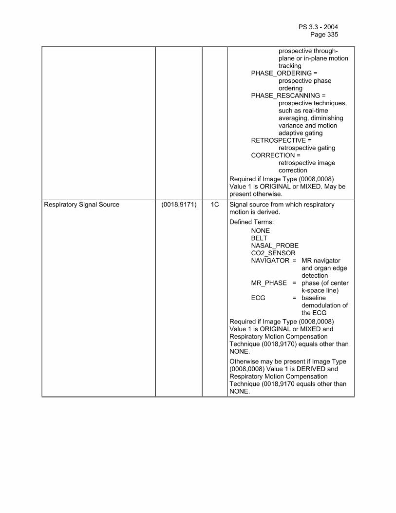
PS 3.3 - 2004 Page 335
prospective through-plane or in-plane motion tracking
PHASE_ORDERING = prospective phase ordering
PHASE_RESCANNING = prospective techniques, such as real-time averaging, diminishing variance and motion adaptive gating
RETROSPECTIVE = retrospective gating
CORRECTION = retrospective image correction
Required if Image Type (0008,0008) Value 1 is ORIGINAL or MIXED. May be present otherwise.
Respiratory Signal Source (0018,9171) 1C Signal source from which respiratory motion is derived. Defined Terms:
NONE BELT NASAL_PROBE CO2_SENSOR NAVIGATOR = MR navigator
and organ edge detection
MR_PHASE = phase (of center k-space line)
ECG = baseline demodulation of the ECG
Required if Image Type (0008,0008) Value 1 is ORIGINAL or MIXED and Respiratory Motion Compensation Technique (0018,9170) equals other than NONE. Otherwise may be present if Image Type (0008,0008) Value 1 is DERIVED and Respiratory Motion Compensation Technique (0018,9170 equals other than NONE.

PS 3.3 - 2004 Page 336
C.7.6.18.3 Bulk Motion Synchronization Module Table C7.6.18-3 specifies the attributes of the Bulk Motion Synchronization Module.
Table C.7.6.18-3 BULK MOTION SYNCHRONIZATION MODULE ATTRIBUTES
Attribute Name Tag Type Attribute Description Bulk Motion Compensation Technique
(0018,9172) 1C Applied technique to reduce bulk or other physiology motion artifacts. Defined Terms:
NONE REALTIME = image acquisition
shorter than motion cycle
GATING = prospective gating TRACKING = prospective
through and/or in-plane motion tracking
RETROSPECTIVE = retrospective gating
CORRECTION = retrospective image correction
Required if Image Type (0008,0008) Value 1 is ORIGINAL or MIXED. May be present otherwise.
Bulk Motion Signal Source (0018,9173) 1C Signal source to measure motion. Defined Terms:
JOINT = joint motion detection
NAVIGATOR = MR navigator and organ edge detection
MR_PHASE = phase (of center k-space line)
Required if Image Type (0008,0008) Value 1 is ORIGINAL or MIXED and Bulk Motion Compensation Technique (0018,9172) equals other than NONE. Otherwise may be present if Image Type (0008,0008) Value 1 is DERIVED and Bulk Motion Compensation Technique (0018,9172) equals other than NONE.

PS 3.3 - 2004 Page 337
C.7.6.19 Supplemental Palette Color Lookup Table Module This module is used in conjunction with Multi-frame IODs that use RGB color in a number of frames. The value of the Pixel Presentation (0008,9205) for such frames equals COLOR.
Table C.7.6.19-1 specifies the Attributes that describe the Lookup table data.
Table C.7.6.19-1 SUPPLEMENTAL PALETTE COLOR TABLE LOOKUP MODULE ATTRIBUTES
Attribute Name Tag Type Attribute Description Red Palette Color Lookup Table Descriptor
(0028,1101) 1 Specifies the format of the Red Palette Color Lookup Table Data (0028,1201). See C.7.6.3.1.5 for further explanation.
Green Palette Color Lookup Table Descriptor
(0028,1102) 1 Specifies the format of the Green Palette Color Lookup Table Data (0028,1202). See C.7.6.3.1.5 for further explanation.
Blue Palette Color Lookup Table Descriptor
(0028,1103) 1 Specifies the format of the Blue Palette Color Lookup table Data (0028,1203). See C.7.6.3.1.5 for further explanation.
Red Palette Color Lookup Table Data
(0028,1201) 1 Red Palette Color Lookup Table Data. See C.7.6.3.1.6 for further explanation.
Green Palette Color Lookup Table Data
(0028,1202) 1 Green Palette Color Lookup Table Data. See C.7.6.3.1.6 for further explanation.
Blue Palette Color Lookup Table Data
(0028,1203) 1 Blue Palette Color Lookup Table Data. See C.7.6.3.1.6 for further explanation.
C.7.7 Patient Summary Module Table C.7-20 defines Attributes that provide summary information about the Patient.
Table C.7-20 PATIENT SUMMARY MODULE ATTRIBUTES
Attribute Name Tag Type Attribute Description Patient's Name (0010,0010) 2 Patient's full name. Patient ID (0010,0020) 2 Primary hospital identification number or
code for the patient.
C.7.8 Study Content Module Table C.7-21 defines Attributes that provide study content information.
Table C.7-21 STUDY CONTENT MODULE ATTRIBUTES
Attribute Name Tag Type Attribute Description Study ID (0020,0010) 2 User or equipment generated Study
identifier Study Instance UID (0020,000D) 1 Unique identifier for the Study Referenced Series Sequence (0008,1115) 1 Sequence of Repeating Items where
each Item includes the Attributes of a Series. Zero or more Items may be

PS 3.3 - 2004 Page 338
included in this Sequence. >Series Instance UID (0020,000E) 1 Unique identifier of the Series. >Retrieve AE Title (0008,0054) 2C Title of the DICOM Application Entity
where the Image(s) may be retrieved on the network. This Attribute shall be present only if the Images may be retrieved at the SERIES level using a media storage. See PS 3.4.
>Storage Media File-Set ID (0088,0130) 2C The user or implementation specific human readable identifier that identifies the Storage Media on which the Image(s) reside. This Attribute shall be present only if the Image(s) may be retrieved at the SERIES level using a media storage.
>Storage Media File-Set UID (0088,0140) 2C Uniquely identifies the Storage Media on which the Image(s) reside. This Attribute shall be present only if the Image(s) may be retrieved at the SERIES level using a media storage.
>Referenced Image Sequence (0008,1140) 1 Sequence of Repeating Items where each Item provides reference to a set of Image SOP Class/SOP Instance pairs that are contained in the Series identified by the Series Instance UID (0020,000E).
>>Referenced SOP Class UID (0008,1150) 2 Uniquely identifies the referenced SOP Class. This Attribute is used only if Images may be retrieved as Single Image SOP Classes.
>>Reference SOP Instance UID (0008,1155) 2 Uniquely identifies the referenced SOP Instance. This Attribute is used only if Images may be retrieved as Single Image SOP Classes.
>>Retrieve AE (0008,0054) 2C Title of the DICOM Application Entity where the Image(s) may be retrieved on the network. This Attribute shall be present only if not present in the Referenced Series Sequence (0008,1115) if the Images may be retrieved at the IMAGE Query/Retrieve Level. See PS 3.4.
>>Storage Media File-Set ID (0088,0130) 2C The user or implementation specific human readable identifier that identifies the Storage Media on which the Image(s) reside. This Attribute shall be present only if not present in the Series Sequence (0008,1115) and if the Image(s) may be retrieved at the IMAGE level using a media storage.
>>Storage Media File-Set UID (0088,0140) 2C Uniquely identifies the Storage Media on which the Image(s) reside. This Attribute shall be present only if not present in the

PS 3.3 - 2004 Page 339
Referenced Series Sequence (0008,1115) and if the Image(s) may be retrieved at the IMAGE level using a media storage.
C.7.9 Palette Color Lookup Table Module Table C.7-22 specifies the Attributes that describe the Lookup table data for images with Palette Color photometric interpretation.
When the Palette Color Lookup Table Module is present, the conditional requirements for the use of Palette Color Lookup Table Data (0028,1201-1203) and Segmented Palette Color Lookup Table Data (0028,1221-1223), described in Table C.7.9, shall take precedence over the conditional requirements described in the Image Pixel Module (See Section C.7.6.3).
Table C.7-22 PALETTE COLOR LOOKUP MODULE
Attribute Name Tag Type Attribute Description Red Palette Color Lookup Table Descriptor
(0028,1101) 1C Specifies the format of the Red Palette Color Lookup Table Data (0028,1201). Required if Photometric Interpretation (0028,0004) has a value of PALETTE COLOR. See C.7.6.3.1.5 for further explanation.
Green Palette Color Lookup Table Descriptor
(0028,1102) 1C Specifies the format of the Green Palette Color Lookup Table Data (0028,1202). Required if Photometric Interpretation (0028,0004) has a value of PALETTE COLOR. See C.7.6.3.1.5 for further explanation.
Blue Palette Color Lookup Table Descriptor
(0028,1103) 1C Specifies the format of the Blue Palette Color Lookup table Data (0028,1203). Required if Photometric Interpretation (0028,0004) has a value of PALETTE COLOR. See C.7.6.3.1.5 for further explanation.
Palette Color Lookup Table UID (0028,1199) 3 Palette Color Lookup Table UID. See C.7.9.1 for further explanation.
Red Palette Color Lookup Table Data
(0028,1201) 1C Red Palette Color Lookup Table Data. Required if Photometric Interpretation (0028,0004) has a value of PALETTE COLOR and segmented data is NOT used. See C.7.6.3.1.6 for further explanation.
Green Palette Color Lookup Table Data
(0028,1202) 1C Green Palette Color Lookup Table Data. Required if Photometric Interpretation (0028,0004) has a value of PALETTE COLOR and segmented data is NOT used. See C.7.6.3.1.6 for further explanation.
Blue Palette Color Lookup Table Data
(0028,1203) 1C Blue Palette Color Lookup Table Data. Required if Photometric Interpretation

PS 3.3 - 2004 Page 340
(0028,0004) has a value of PALETTE COLOR and segmented data is NOT used. See C.7.6.3.1.6 for further explanation.
Segmented Red Palette Color Lookup Table Data
(0028,1221) 1C Segmented Red Palette Color Lookup Table Data. Required if Photometric Interpretation (0028,0004) has a value of PALETTE COLOR and segmented data is used. See C.7.9.2 for further explanation.
Segmented Green Palette Color Lookup Table Data
(0028,1222) 1C Segmented Green Palette Color Lookup Table Data. Required if Photometric Interpretation (0028,0004) has a value of PALETTE COLOR and segmented data is used. See C.7.9.2 for further explanation.
Segmented Blue Palette Color Lookup Table Data
(0028,1223) 1C Segmented Blue Palette Color Lookup Table Data. Required if Photometric Interpretation (0028,0004) has a value of PALETTE COLOR and segmented data is used. See C.7.9.2 for further explanation.
C.7.9.1 Palette Color Lookup Table UID This data element uniquely identifies a palette color lookup table set (red, green, blue).
Note: This can be used to avoid reloading a palette if a system already has that palette loaded without examining all the data entries in the palette.
C.7.9.2 Segmented Palette Color Lookup Table Data The Segmented Palette Color Lookup Table Data (0028,1221-1223) is stored as a series of segments, see Table C.7-23. When the segments are expanded into the actual lookup table data, it shall have the number of table entries specified by the first value of the Palette Color Lookup Table Descriptors (0028,1101-1103), Number of Table Entries.
These lookup tables shall be used only when segmented lookup table data use is desriable and there is a single sample per pixel (single image plane) in the image.
Table C.7-23 COMPRESSED PALETTE COLOR LOOKUP TABLE DATA
Segment 0
Segment 1
...
Segment n
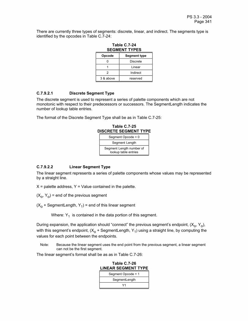
PS 3.3 - 2004 Page 341
There are currently three types of segments: discrete, linear, and indirect. The segments type is identified by the opcodes in Table C.7-24:
Table C.7-24 SEGMENT TYPES
Opcode Segment type
0 Discrete
1 Linear
2 Indirect
3 & above reserved
C.7.9.2.1 Discrete Segment Type The discrete segment is used to represent a series of palette components which are not monotonic with respect to their predecessors or successors. The SegmentLength indicates the number of lookup table entries.
The format of the Discrete Segment Type shall be as in Table C.7-25:
Table C.7-25 DISCRETE SEGMENT TYPE
Segment Opcode = 0
Segment Length
Segment Length number of lookup table entries
C.7.9.2.2 Linear Segment Type The linear segment represents a series of palette components whose values may be represented by a straight line.
X = palette address, Y = Value contained in the palette.
(Xo, Yo) = end of the previous segment
(Xo + SegmentLength, Y1) = end of this linear segment
Where: Y1 is contained in the data portion of this segment.
During expansion, the application should “connect” the previous segment’s endpoint, (Xo, Yo), with this segment’s endpoint, (Xo + SegmentLength, Y1) using a straight line, by computing the values for each point between the endpoints.
Note: Because the linear segment uses the end point from the previous segment, a linear segment can not be the first segment.
The linear segment’s format shall be as as in Table C.7-26:
Table C.7-26 LINEAR SEGMENT TYPE
Segment Opcode = 1
SegmentLength
Y1

PS 3.3 - 2004 Page 342
C.7.9.2.3 Indirect Segment Type The indirect segment allows the re-use of repetitive regions within lookup table without respecifying the segment. The opcode is followed by the number of segments to copy and one offset pointer to the first segment to copy. The byte offset is relative to the beginning of the lookup table. For example, if an indirect segment wants to point to the first segment, then the offset will be zero. The offset is a 32 bit value but is stored in the segment as a least significant 16 bit value followed by a most significant 16 bit value. An indirect segment shall not point to or copy another indirect segment. This avoids the need for recursion and also avoids the possibility of infinite loops.
The indirect segment’s format shall be as follows:
Table C.7-27 INDIRECT SEGMENT TYPE
Segment Opcode = 2
Number of segments to copy
Least significant 16 bits of byte offset to first segment to copy
Most significant 16 bits of byte offset to first segment to copy

PS 3.3 - 2004 Page 343
C.8 MODALITY SPECIFIC MODULES
C.8.1 Computed Radiography Modules This Section describes Computed Radiography Series and Image Modules. These Modules contain Attributes that are specific to Computed Radiography images. There is no Computed Radiography Equipment Module.
C.8.1.1 CR Series Module Table C.8-1 contains IOD Attributes that describe a computed radiography series performed on the patient.
Table C.8-1 CR SERIES MODULE ATTRIBUTES
Attribute Name Tag Type Attribute Description Body Part Examined (0018,0015) 2 Text description of the part of the body
examined. Defined Terms: SKULL CSPINE TSPINE LSPINE SSPINE COCCYX CHEST CLAVICLE BREAST ABDOMEN PELVIS HIP SHOULDER ELBOW KNEE ANKLE HAND FOOT EXTREMITY HEAD HEART NECK LEG ARM JAW
View Position (0018,5101) 2 Radiographic view associated with Patient Position (0018,5100). Defined Terms: AP = Anterior/Posterior PA = Posterior/Anterior LL = Left Lateral RL = Right Lateral RLD = Right Lateral Decubitus LLD = Left Lateral Decubitus RLO = Right Lateral Oblique LLO = Left Lateral Oblique
Filter Type (0018,1160) 3 Label for the type of filter inserted into the x-ray beam

PS 3.3 - 2004 Page 344
Collimator/grid Name (0018,1180) 3 Label describing any grid inserted. Focal Spot (0018,1190) 3 Size of the focal spot in mm. For devices
with variable focal spot or multiple focal spots, small dimension followed by large dimension.
Plate Type (0018,1260) 3 Label of the type of storage phosphor plates used in this series
Phosphor Type (0018,1261) 3 Label of type of phosphor on the plates
C.8.1.2 CR Image Module Table C.8-2 contains IOD Attributes that describe computed radiography images.
Table C.8-2 CR IMAGE MODULE ATTRIBUTES
Attribute Name Tag Type Attribute Description Photometric Interpretation (0028,0004) 1 Specifies the intended interpretation of the
pixel data. Shall have one of the following Enumerated Values: MONOCHROME1 MONOCHROME2
KVP (0018,0060) 3 Peak kilo voltage output of the x-ray generator used
Plate ID (0018,1004) 3 The ID or serial number of the sensing plate upon which the image was acquired
Distance Source to Detector (0018,1110) 3 Distance in mm from source to detector center.
Note: This value is traditionally referred to as Source Image Receptor Distance (SID).
Distance Source to Patient (0018,1111) 3 Distance in mm from source to isocenter (center of field of view) .
Note: This value is traditionally referred to as Source Object Distance (SOD).
Exposure Time (0018,1150) 3 Time of x-ray exposure in msec X-ray Tube Current (0018,1151) 3 X-ray Tube Current in mA. Exposure (0018,1152) 3 The exposure expressed in mAs, for
example calculated from Exposure Time and X-ray Tube Current.
Exposure in µAs (0018,1153) 3 The exposure expressed in µAs, for example calculated from Exposure Time and X-ray Tube Current.
Imager Pixel Spacing (0018,1164) 3 Physical distance measured at the front plane of the Image Receptor housing between the center of each pixel. Specified by a numeric pair - row spacing value (delimiter) column spacing value - in mm. In the case of CR, the front plane is defined

PS 3.3 - 2004 Page 345
to be the external surface of the CR plate closest to the patient and radiation source.
Generator Power (0018,1170) 3 Power in kW to the x-ray generator. Acquisition Device Processing Description
(0018,1400) 3 Describes device-specific processing associated with the image (e.g. Organ Description)
Acquisition Device Processing Code (0018,1401) 3 Code representing the device-specific processing associated with the image (e.g. CR Organ Filtering code)
Cassette Orientation (0018,1402) 3 Orientation of cassette, used to properly position the image for display. Enumerated Values: LANDSCAPE PORTRAIT
Cassette Size (0018,1403) 3 Size of cassette. Defined Terms: 18CMX24CM 8INX10IN 24CMX30CM 10INX12IN 30CMX35CM 30CMX40CM 11INX14IN 35CMX35CM 14INX14IN 35CMX43CM 14INX17IN
Exposures on Plate (0018,1404) 3 Total number of x-ray exposures that have been made on the plate identified in Plate ID (0018,1004)
Relative X-ray Exposure (0018,1405) 3 Relative x-ray exposure on the plate. Meaning of values is implementation specific. May be used to adjust the dynamic range of the plate digitizer (scanner).
Sensitivity (0018,6000) 3 Read out sensitivity. Include 'General Anatomy Optional Macro' Table 10-7 Defined Context ID for the Anatomic
Region Sequence is 4009.

PS 3.3 - 2004 Page 346
C.8.2 CT Modules This Section describes the CT Image Module. This Module contains all Attributes that are specific to CT images.
C.8.2.1 CT Image Module The table in this Section contains IOD Attributes that describe CT images.
Table C.8-3 CT IMAGE MODULE ATTRIBUTES
Attribute Name Tag Type Attribute Description Image Type (0008,0008) 1 Image identification characteristics. See
C.8.2.1.1.1 for specialization. Samples per Pixel (0028,0002) 1 Number of samples (planes) in this
image. See C.8.2.1.1.2 for specialization. Photometric Interpretation (0028,0004) 1 Specifies the intended interpretation of
the pixel data. See C.8.2.1.1.3 for specialization.
Bits Allocated (0028,0100) 1 Number of bits allocated for each pixel sample. Each sample shall have the same number of bits allocated. See C.8.2.1.1.4 for specialization.
Bits Stored (0028,0101) 1 Number of bits stored for each pixel sample. Each sample shall have the same number of bits stored. See C.8.2.1.1.5 for specialization.
High Bit (0028,0102) 1 Most significant bit for pixel sample data. Each sample shall have the same high bit. See C.8.2.1.1.6 for specialization.
Rescale Intercept (0028, 1052) 1 The value b in relationship between stored values (SV) and Hounsfield (HU). HU = m*SV+b
Rescale Slope (0028,1053) 1 m in the equation specified in Rescale Intercept (0028,1052).
KVP (0018,0060) 2 Peak kilo voltage output of the x-ray generator used
Acquisition Number (0020,0012) 2 A number identifying the single continuous gathering of data over a period of time which resulted in this image
Scan Options (0018,0022) 3 Parameters of scanning sequence. Data Collection Diameter (0018,0090) 3 The diameter in mm of the region over
which data were collected Reconstruction Diameter (0018,1100) 3 Diameter in mm of the region from within
which data were used in creating the reconstruction of the image. Data may exist outside this region and portions of the patient may exist outside this region.
Distance Source to Detector (0018,1110) 3 Distance in mm from source to detector center.
Note: This value is traditionally referred

PS 3.3 - 2004 Page 347
to as Source Image Receptor Distance (SID).
Distance Source to Patient (0018,1111) 3 Distance in mm from source to isocenter (center of field of view).
Note: This value is traditionally referred to as Source Object Distance (SOD).
Gantry/Detector Tilt (0018,1120) 3 Nominal angle of tilt in degrees of the scanning gantry. Not intended for mathematical computations.
Table Height (0018,1130) 3 The distance in mm of the top of the patient table to the center of rotation; below the center is positive.
Rotation Direction (0018,1140) 3 Direction of rotation of the source when relevant, about nearest principal axis of equipment. Enumerated Values: CW = clockwise CC = counter clockwise
Exposure Time (0018,1150) 3 Time of x-ray exposure in msec X-ray Tube Current (0018,1151) 3 X-ray Tube Current in mA. Exposure (0018,1152) 3 The exposure expressed in mAs, for
example calculated from Exposure Time and X-ray Tube Current.
Exposure in µAs (0018,1153) 3 The exposure expressed in µAs, for example calculated from Exposure Time and X-ray Tube Current.
Filter Type (0018,1160) 3 Label for the type of filter inserted into the x-ray beam.
Generator Power (0018,1170) 3 Power in kW to the x-ray generator. Focal Spot (0018,1190) 3 Size of the focal spot in mm. For devices
with variable focal spot or multiple focal spots, small dimension followed by large dimension.
Convolution Kernel (0018,1210) 3 A label describing the convolution kernel or algorithm used to reconstruct the data
Revolution Time (0018,9305) 3 The time in seconds of a complete revolution of the source around the gantry orbit.
Single Collimation Width (0018,9306) 3 The width of a single row of acquired data (in mm).
Note: Adjacent physical detector rows may have been combined to form a single effective acquisition row.
Total Collimation Width (0018,9307) 3 The width of the total collimation (in mm) over the area of active x-ray detection.
Note: This will be equal the number of effective detector rows multiplied

PS 3.3 - 2004 Page 348
by single collimation width.
Table Speed (0018,9309) 3 The distance in mm that the table moves in one second during the gathering of data that resulted in this image.
Table Feed per Rotation (0018,9310) 3 Motion of the table (in mm) during a complete revolution of the source around the gantry orbit.
CT Pitch Factor (0018,9311) 3 Ratio of the Table Feed per Rotation (0018, 9310) to the Total Collimation Width (0018, 9307).
Include 'General Anatomy Optional Macro' Table 10-7 Defined Context ID for the Anatomic Region Sequence is 4030.
C.8.2.1.1 CT Image Attribute Descriptions C.8.2.1.1.1 Image Type For CT Images, Image Type (0008,0008) is specified to be Type 1 and uses one of the following Defined Terms for Value 3:
AXIAL identifies a CT Axial Image LOCALIZER identifies a CT Localizer Image
C.8.2.1.1.2 Samples Per Pixel For CT Images, Samples per Pixel (0028,0002) shall have an Enumerated Value of 1.
C.8.2.1.1.3 Photometric Interpretation For CT Images, Photometric Interpretation (0028,0004) shall have one of the following Enumerated Values:
MONOCHROME1 MONOCHROME2
See C.7.6.3.1.1.2 for definition of these terms.
C.8.2.1.1.4 Bits Allocated For CT Images, Bits Allocated (0028,0100) shall have the Enumerated Value of 16.
C.8.2.1.1.5 Bits Stored For CT Images, Bits Stored (0028,0101) shall have the Enumerated Values of 12 to 16.
C.8.2.1.1.6 High Bit For CT Images, High Bit (0028,0102) shall have only the Enumerated Value of one less than the value sent in Bits Stored.
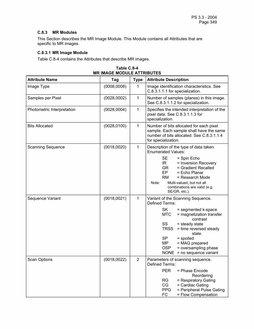
PS 3.3 - 2004 Page 349
C.8.3 MR Modules This Section describes the MR Image Module. This Module contains all Attributes that are specific to MR images.
C.8.3.1 MR Image Module Table C.8-4 contains the Attributes that describe MR images.
Table C.8-4 MR IMAGE MODULE ATTRIBUTES
Attribute Name Tag Type Attribute Description Image Type (0008,0008) 1 Image identification characteristics. See
C.8.3.1.1.1 for specialization. Samples per Pixel (0028,0002) 1 Number of samples (planes) in this image.
See C.8.3.1.1.2 for specialization. Photometric Interpretation (0028,0004) 1 Specifies the intended interpretation of the
pixel data. See C.8.3.1.1.3 for specialization.
Bits Allocated (0028,0100) 1 Number of bits allocated for each pixel sample. Each sample shall have the same number of bits allocated. See C.8.3.1.1.4 for specialization.
Scanning Sequence (0018,0020) 1 Description of the type of data taken. Enumerated Values: SE = Spin Echo IR = Inversion Recovery GR = Gradient Recalled EP = Echo Planar RM = Research Mode
Note: Multi-valued, but not all combinations are valid (e.g. SE/GR, etc.).
Sequence Variant (0018,0021) 1 Variant of the Scanning Sequence. Defined Terms: SK = segmented k-space MTC = magnetization transfer contrast SS = steady state TRSS = time reversed steady state SP = spoiled MP = MAG prepared OSP = oversampling phase NONE = no sequence variant
Scan Options (0018,0022) 2 Parameters of scanning sequence. Defined Terms: PER = Phase Encode Reordering RG = Respiratory Gating CG = Cardiac Gating PPG = Peripheral Pulse Gating FC = Flow Compensation

PS 3.3 - 2004 Page 350
PFF = Partial Fourier - Frequency PFP = Partial Fourier - Phase SP = Spatial Presaturation FS = Fat Saturation
MR Acquisition Type (0018,0023) 2 Identification of data encoding scheme. Enumerated Values: 2D = frequency x phase 3D = frequency x phase x phase
Repetition Time (0018,0080) 2C The period of time in msec between the beginning of a pulse sequence and the beginning of the succeeding (essentially identical) pulse sequence. Required except when Scanning Sequence (0018,0020) is EP and Sequence Variant (0018,0021) is not SK.
Echo Time (0018,0081) 2 Time in ms between the middle of the excitation pulse and the peak of the echo produced (kx=0). In the case of segmented k-space, the TE(eff) is the time between the middle of the excitation pulse to the peak of the echo that is used to cover the center of k-space (i.e.-kx=0, ky=0).
Echo Train Length (0018,0091) 2 Number of lines in k-space acquired per excitation per image.
Inversion Time (0018,0082) 2C Time in msec after the middle of inverting RF pulse to middle of excitation pulse to detect the amount of longitudinal magnetization. Required if Scanning Sequence (0018,0020) has values of IR.
Trigger Time (0018,1060) 2C Time, in msec, between peak of the R wave and the peak of the echo produced. In the case of segmented k-space, the TE(eff) is the time between the peak of the echo that is used to cover the center of k-space. Required for Scan Options (0018,0022) which include heart gating (e.g. CG, PPG, etc.)
Sequence Name (0018,0024) 3 User defined name for the Scanning Sequence (0018,0020) and Sequence Variant (0018,0021) combination.
Angio Flag (0018,0025) 3 Angio Image Indicator. Primary image for Angio processing. Enumerated Values: Y = Image is Angio N = Image is not Angio
Number of Averages (0018,0083) 3 Number of times a given pulse sequence is repeated before any parameter is changed
Imaging Frequency (0018,0084) 3 Precession frequency in MHz of the nucleus being addressed
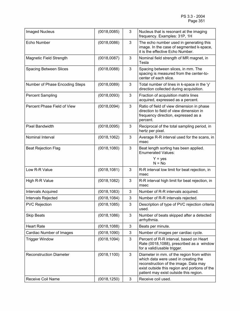
PS 3.3 - 2004 Page 351
Imaged Nucleus (0018,0085) 3 Nucleus that is resonant at the imaging frequency. Examples: 31P, 1H
Echo Number (0018,0086) 3 The echo number used in generating this image. In the case of segmented k-space, it is the effective Echo Number.
Magnetic Field Strength (0018,0087) 3 Nominal field strength of MR magnet, in Tesla
Spacing Between Slices (0018,0088) 3 Spacing between slices, in mm. The spacing is measured from the center-to-center of each slice.
Number of Phase Encoding Steps (0018,0089) 3 Total number of lines in k-space in the 'y' direction collected during acquisition.
Percent Sampling (0018,0093) 3 Fraction of acquisition matrix lines acquired, expressed as a percent.
Percent Phase Field of View (0018,0094) 3 Ratio of field of view dimension in phase direction to field of view dimension in frequency direction, expressed as a percent.
Pixel Bandwidth (0018,0095) 3 Reciprocal of the total sampling period, in hertz per pixel.
Nominal Interval (0018,1062) 3 Average R-R interval used for the scans, in msec
Beat Rejection Flag (0018,1080) 3 Beat length sorting has been applied. Enumerated Values: Y = yes N = No
Low R-R Value (0018,1081) 3 R-R interval low limit for beat rejection, in msec
High R-R Value (0018,1082) 3 R-R interval high limit for beat rejection, in msec
Intervals Acquired (0018,1083) 3 Number of R-R intervals acquired. Intervals Rejected (0018,1084) 3 Number of R-R intervals rejected. PVC Rejection (0018,1085) 3 Description of type of PVC rejection criteria
used. Skip Beats (0018,1086) 3 Number of beats skipped after a detected
arrhythmia. Heart Rate (0018,1088) 3 Beats per minute. Cardiac Number of Images (0018,1090) 3 Number of images per cardiac cycle. Trigger Window (0018,1094) 3 Percent of R-R interval, based on Heart
Rate (0018,1088), prescribed as a window for a valid/usable trigger.
Reconstruction Diameter (0018,1100) 3 Diameter in mm. of the region from within which data were used in creating the reconstruction of the image. Data may exist outside this region and portions of the patient may exist outside this region.
Receive Coil Name (0018,1250) 3 Receive coil used.

PS 3.3 - 2004 Page 352
Transmit Coil Name (0018,1251) 3 Transmit coil used. Acquisition Matrix (0018,1310) 3 Dimensions of the acquired frequency
/phase data before reconstruction. Multi-valued: frequency rows\frequency columns\phase rows\phase columns.
In-plane Phase Encoding Direction (0018,1312) 3 The axis of phase encoding with respect to the image. Enumerated Values: ROW = phase encoded in rows. COL = phase encoded in columns.
Flip Angle (0018,1314) 3 Steady state angle in degrees to which the magnetic vector is flipped from the magnetic vector of the primary field.
SAR (0018,1316) 3 Calculated whole body Specific Absorption Rate in watts/kilogram.
Variable Flip Angle Flag (0018,1315) 3 Flip angle variation applied during image acquisition. Enumerated Values: Y = yes N = no
dB/dt (0018,1318) 3 The rate of change of the gradient coil magnetic flux density with time (T/s).
Temporal Position Identifier (0020,0100) 3 Temporal order of a dynamic or functional set of Images.
Number of Temporal Positions (0020,0105) 3 Total number of temporal positions prescribed.
Temporal Resolution (0020,0110) 3 Time delta between Images in a dynamic of functional set of Images.
Include 'General Anatomy Optional Macro' Table 10-7 Defined Context ID for the Anatomic Region Sequence is 4030.
C.8.3.1.1 MR Image Attribute Descriptions C.8.3.1.1.1 Image Type For MR Images, Image Type (0008,0008) is specified to be Type 1 and use one of the following Defined Terms for Value 3:
MPR PROJECTION IMAGE T1 MAP T2 MAP DIFFUSION MAP DENSITY MAP PHASE MAP VELOCITY MAP IMAGE ADDITION PHASE SUBTRACT MODULUS SUBTRACT OTHER
C.8.3.1.1.2 Samples Per Pixel For MR Images, Samples per Pixel (0028,0002) shall have an Enumerated Value of 1.

PS 3.3 - 2004 Page 353
C.8.3.1.1.3 Photometric Interpretation For MR Images, Photometric Interpretation (0028,0004) shall have one of the following Enumerated Values:
MONOCHROME1 MONOCHROME2
See C.7.6.3.1.2 for definition of these terms.
C.8.3.1.1.4 Bits Allocated For MR Images, Bits Allocated (0028,0100) shall have the Enumerated Value of 16.

PS 3.3 - 2004 Page 354
C.8.4 Nuclear Medicine Modules This Section describes Nuclear Medicine Series, Equipment, and Image Modules. These Modules contain Attributes that are specific to the NM Image IOD.
Note: There are some cases where it may be necessary to use several SOP Instances to encode a single NM acquisition. For example, the matrix size must remain constant within a SOP instance. Multiple matrix sizes require multiple SOP instances. Similarly, multiple gated stress levels require separate SOP instances for each stress level. However, a receiving AE is not expected to recombine them.
C.8.4.1 NM Series Module (Retired) Section C.8.4.1 was defined in a previous version of the DICOM Standard. The Section is now retired.
C.8.4.2 NM Equipment Module (Retired) Section C.8.4.2 was defined in a previous version of the DICOM Standard. The Section is now retired.
C.8.4.3 NM Image Module (Retired) Section C.8.4.3 was defined in a previous version of the DICOM Standard. The Section is now retired.
C.8.4.4 NM SPECT Acquisition Image Module (Retired) Section C.8.4.4 was defined in a previous version of the DICOM Standard. The Section is now retired.
C.8.4.5 NM Multi-gated Acquisition Image Module (Retired) Section C.8.4.5 was defined in a previous version of the DICOM Standard. The Section is now retired.

PS 3.3 - 2004 Page 355
C.8.4.6 NM/PET Patient Orientation Module Table C.8-5 specifies the Attributes that describe the NM/PET Patient Orientation.
Table C.8-5 NM/PET PATIENT ORIENTATION MODULE ATTRIBUTES
Attribute Name Tag Type Attribute Description Patient Orientation Code Sequence (0054,0410) 2 Sequence that describes the orientation of
the patient with respect to gravity. See C.8.4.6.1.1 for further explanation.
>Include ‘Code Sequence Macro’ Table 8.8-1 Baseline Context ID is 19. The Coding Scheme Designator (0008,0102) shall have an Enumerated Value of “99SDM” for historical reasons. Code Meaning (0008,0104) shall be Type 3 for historical reasons.
> Patient Orientation Modifier Code Sequence
(0054,0412) 2C Patient Orientation Modifier. Required if needed to fully specify the orientation of the patient with respect to gravity. See C.8.4.6.1.2 for further explanation.
>>Include ‘Code Sequence Macro’ Table 8.8-1 Baseline Context ID is 20. The Coding Scheme Designator (0008,0102) shall have an Enumerated Value of “99SDM” for historical reasons. Code Meaning (0008,0104) shall be Type 3 for historical reasons.
Patient Gantry Relationship Code Sequence
(0054,0414) 2 Sequence which describes the orientation of the patient with respect to the gantry. See Section C.8.4.6.1.3 for further explanation.
>Include ‘Code Sequence Macro’ Table 8.8-1 Baseline Context ID is 21. The Coding Scheme Designator (0008,0102) shall have an Enumerated Value of “99SDM” for historical reasons. Code Meaning (0008,0104) shall be Type 3 for historical reasons.
C.8.4.6.1 NM/PET Patient Orientation Attribute Descriptions C.8.4.6.1.1 Patient Orientation Code Sequence The Patient Orientation Code Sequence (0054,0410) is used to describe the orientation of the patient with respect to gravity, and is independent of the position in the gantry. Only a single Item shall be permitted in this sequence.
C.8.4.6.1.2 Patient Orientation Modifier Code Sequence The Patient Orientation Modifier Code Sequence (0054,0412) is used to modify or enhance the orientation specified by Patient Orientation Code Sequence (0054,0410). Only a single Item shall be permitted in this sequence.

PS 3.3 - 2004 Page 356
C.8.4.6.1.3 Patient Gantry Relationship Code Sequence Patient Gantry Relationship Code Sequence (0054,0414) is used to describe the patient direction within the gantry, such as head-first or feet-first. When imaging the extremities, these directions are related to normal anatomic position.
Example: In normal anatomic position, the fingers point towards the feet.
Only a single Item shall be permitted in this sequence.
C.8.4.7 NM Image Pixel Module Table C.8-6 specifies the Attributes that describe the pixel data of a NM image.
Table C.8-6 NM IMAGE PIXEL MODULE ATTRIBUTES
Attribute Name Tag Type Attribute Description Samples per Pixel (0028,0002) 1 Number of samples (color planes) in this
image. The value shall be 1. Photometric Interpretation (0028,0004) 1 Specifies the intended interpretation of the
pixel data. See C.8.4.7.1.1 for further explanation.
Bits Allocated (0028,0100) 1 Number of bits allocated for each pixel sample. Each sample shall have the same number of bits allocated. Enumerated Values: 8, 16.
Bits Stored (0028,0101) 1 Number of bits stored for each pixel sample. Each sample shall have the same number of bits stored. The value shall be the same as the value in Bits Allocated (0028,0100).
High Bit (0028,0102) 1 Most significant bit for pixel sample data. Each sample shall have the same high bit.Shall be one less than the value in Bits Stored (0028,0101).
Pixel Spacing (0028,0030) 2 Physical distance in the patient between the center of each pixel, specified by a numeric pair - adjacent row spacing (delimiter) adjacent column spacing, in mm.
C.8.4.7.1 NM Image Pixel Attribute Descriptions C.8.4.7.1.1 Photometric Interpretation For NM Images, Photometric Interpretation (0028,0004) shall have one of the following Enumerated Values:
MONOCHROME2 PALETTE COLOR
See C.7.6.3.1.2 for definition of these terms.
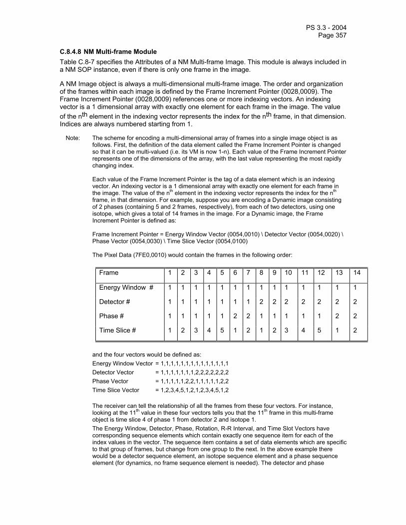
PS 3.3 - 2004 Page 357
C.8.4.8 NM Multi-frame Module Table C.8-7 specifies the Attributes of a NM Multi-frame Image. This module is always included in a NM SOP instance, even if there is only one frame in the image.
A NM Image object is always a multi-dimensional multi-frame image. The order and organization of the frames within each image is defined by the Frame Increment Pointer (0028,0009). The Frame Increment Pointer (0028,0009) references one or more indexing vectors. An indexing vector is a 1 dimensional array with exactly one element for each frame in the image. The value of the nth element in the indexing vector represents the index for the nth frame, in that dimension. Indices are always numbered starting from 1.
Note: The scheme for encoding a multi-dimensional array of frames into a single image object is as follows. First, the definition of the data element called the Frame Increment Pointer is changed so that it can be multi-valued (i.e. its VM is now 1-n). Each value of the Frame Increment Pointer represents one of the dimensions of the array, with the last value representing the most rapidly changing index. Each value of the Frame Increment Pointer is the tag of a data element which is an indexing vector. An indexing vector is a 1 dimensional array with exactly one element for each frame in the image. The value of the nth element in the indexing vector represents the index for the nth frame, in that dimension. For example, suppose you are encoding a Dynamic image consisting of 2 phases (containing 5 and 2 frames, respectively), from each of two detectors, using one isotope, which gives a total of 14 frames in the image. For a Dynamic image, the Frame Increment Pointer is defined as: Frame Increment Pointer = Energy Window Vector (0054,0010) \ Detector Vector (0054,0020) \ Phase Vector (0054,0030) \ Time Slice Vector (0054,0100) The Pixel Data (7FE0,0010) would contain the frames in the following order:
Frame 1 2 3 4 5 6 7 8 9 10 11 12 13 14
Energy Window # 1 1 1 1 1 1 1 1 1 1 1 1 1 1
Detector # 1 1 1 1 1 1 1 2 2 2 2 2 2 2
Phase # 1 1 1 1 1 2 2 1 1 1 1 1 2 2
Time Slice # 1 2 3 4 5 1 2 1 2 3 4 5 1 2
and the four vectors would be defined as: Energy Window Vector = 1,1,1,1,1,1,1,1,1,1,1,1,1,1 Detector Vector = 1,1,1,1,1,1,1,2,2,2,2,2,2,2 Phase Vector = 1,1,1,1,1,2,2,1,1,1,1,1,2,2 Time Slice Vector = 1,2,3,4,5,1,2,1,2,3,4,5,1,2
The receiver can tell the relationship of all the frames from these four vectors. For instance,
looking at the 11th value in these four vectors tells you that the 11th frame in this multi-frame object is time slice 4 of phase 1 from detector 2 and isotope 1.
The Energy Window, Detector, Phase, Rotation, R-R Interval, and Time Slot Vectors have corresponding sequence elements which contain exactly one sequence item for each of the index values in the vector. The sequence item contains a set of data elements which are specific to that group of frames, but change from one group to the next. In the above example there would be a detector sequence element, an isotope sequence element and a phase sequence element (for dynamics, no frame sequence element is needed). The detector and phase

PS 3.3 - 2004 Page 358
sequence elements would contain two sequence items (because there were 2 detectors and 2 phases).
Table C.8-7 NM MULTI-FRAME MODULE ATTRIBUTES
Attribute Name Tag Type Attribute Description Frame Increment Pointer (0028,0009) 1 Contains the Data Element Tags of one or
more frame index vectors. See C.8.4.8.1.1 for further specialization.
Energy Window Vector (0054,0010) 1C An array which contains the energy window number for each frame. Required if the value of the Frame Increment Pointer (0028,0009) includes the Tag for Energy Window Vector (0054,0010). See C.8.4.8.1.2 for specialization.
Number of Energy Windows (0054,0011) 1 Number of energy window groupings. See C.8.4.8.1.2 for specialization.
Detector Vector (0054,0020) 1C An array which contains the detector number for each frame. Required if the value of the Frame Increment Pointer (0028,0009) includes the Tag for Detector Vector (0054,0020). See C.8.4.8.1.3 for specialization.
Number of Detectors (0054,0021) 1 Number of detectors. See C.8.4.8.1.3 for specialization.
Phase Vector (0054,0030) 1C An array which contains the phase number for each frame. Required if the value of the Frame Increment Pointer (0028,0009) includes the Tag for Phase Vector (0054,0030). See C.8.4.8.1.4 for specialization.
Number of Phases (0054,0031) 1C Number of phases. Required if the value of the Frame Increment Pointer (0028,0009) includes the Tag for Phase Vector (0054,0030). See C.8.4.8.1.4 for specialization.
Rotation Vector (0054,0050) 1C An array which contains the rotation number for each frame. Required if the value of the Frame Increment Pointer (0028,0009) includes the Tag for Rotation Vector (0054,0050). See C.8.4.8.1.5 for specialization.
Number of Rotations (0054,0051) 1C Number of rotations. Required if Image Type (0008,0008), Value 3 is TOMO, GATED TOMO, RECON TOMO, or RECON GATED TOMO. See C.8.4.8.1.5 for specialization.

PS 3.3 - 2004 Page 359
R-R Interval Vector (0054,0060) 1C An array which contains the R-R interval number for each frame. Required if the value of the Frame Increment Pointer (0028,0009) includes the Tag for R-R Interval Vector (0054,0060). See C.8.4.8.1.6 for specialization.
Number of R-R Intervals (0054,0061) 1C Number of R-R intervals. Required if the value of the Frame Increment Pointer (0028,0009) includes the Tag for R-R Interval Vector (0054,0060). See C.8.4.8.1.6 for specialization.
Time Slot Vector (0054,0070) 1C An array which contains the time slot number for each frame. Required if the value of the Frame Increment Pointer (0028,0009) includes the Tag for Time Slot Vector (0054,0070). See C.8.4.8.1.7 for specialization.
Number of Time Slots (0054,0071) 1C Number of time slots. Required if the value of the Frame Increment Pointer (0028,0009) includes the Tag for Time Slot Vector (0054,0070). See C.8.4.8.1.7 for specialization.
Slice Vector (0054,0080) 1C An array which contains the spatial slice number for each frame. Required if the value of the Frame Increment Pointer (0028,0009) includes the Tag for Slice Vector (0054,0080). See C.8.4.8.1.8 for specialization.
Number of Slices (0054,0081) 1C Number of slices. Required if the value of the Frame Increment Pointer (0028,0009) includes the Tag for Slice Vector (0054,0080). See C.8.4.8.1.8 for specialization.
Angular View Vector (0054,0090) 1C An array which contains the angular view number for each frame. Required if the value of the Frame Increment Pointer (0028,0009) includes the Tag for Angular View Vector (0054,0090). See C.8.4.8.1.9 for specialization.
Time Slice Vector (0054,0100) 1C An array which contains the time slice number for each frame. Required if the value of the Frame Increment Pointer (0028,0009) includes the Tag for Time Slice Vector (0054,0100). See C.8.4.8.1.10 for specialization.
Note: Per the rules in PS 3.5, if a data element of Type 1C or 2C is not required, it shall not be included.

PS 3.3 - 2004 Page 360
C.8.4.8.1 NM Multi-Frame Attribute Descriptions C.8.4.8.1.1 Frame Increment Pointer By definition, NM Images are multi-dimensional Multi-frame Images. The value of the Frame Increment Pointer (0028,0009) contains the Tag for one or more frame indexing vectors. This determines the number of dimensions of frame indices in the image, and the order in which these indices vary from one frame to the next, with the last Tag indicating the most rapidly changing index. The Enumerated Values for the Frame Increment Pointer (0028,0009) are determined by the Image Type (0008,0008), Value 3, as shown in Table C.8-8.
Table C.8-8 ENUMERATED VALUES FOR FRAME INCREMENT POINTER
Image Type (0008,0008), Value 3 Frame Increment Pointer (0028,0009) STATIC or WHOLE BODY 0054H 0010H \ 0054H 0020H
Sequencing is by Energy Window Vector (0054,0010), Detector Vector (0054,0020).
DYNAMIC 0054H 0010H \ 0054H 0020H \ 0054H 0030H \ 0054H 0100H Sequencing is by Energy Window Vector (0054,0010), Detector Vector (0054,0020), Phase Vector (0054,0030), Time Slice Vector (0054,0100)
GATED 0054H 0010H \ 0054H 0020H \ 0054H 0060H \ 0054H 0070H Sequencing is by Energy Window Vector (0054,0010), Detector Vector (0054,0020), R-R Interval Vector(0054,0060), Time Slot Vector (0054,0070)
TOMO 0054H 0010H \ 0054H 0020H \ 0054H 0050H \ 0054H 0090H Sequencing is by Energy Window Vector (0054,0010), Detector Vector (0054,0020), Rotation Vector (0054,0050), Angular View Vector (0054,0090)
GATED TOMO 0054H 0010H \ 0054H 0020H \ 0054H 0050H \ 0054H 0060H \ 0054H 0070H \ 0054H 0090H Sequencing is by Energy Window Vector (0054,0010), Detector Vector (0054,0020), Rotation Vector (0054,0050), R-R Interval Vector (0054,0060), Time Slot Vector (0054,0070), Angular View Vector (0054,0090).
RECON TOMO 0054H 0080H Sequencing is by Slice Vector (0054,0080)
RECON GATED TOMO 0054H 0060H \ 0054H 0070H \ 0054H 0080H Sequencing is by R-R Interval Vector (0054,0060), Time Slot Vector (0054,0070), Slice Vector (0054,0080)
C.8.4.8.1.2 Number of Energy Windows and Energy Window Vector Number of Energy Windows (0054,0011) is the number of distinct energy window groupings acquired in this image. See C.8.4.10.1. When Image Type (0008,0008), Value 3, is RECON TOMO or RECON GATED TOMO, then the Number of Energy Windows (0054,0011) shall be 1.
Energy Window Vector (0054,0010) is an indexing vector. The value of the nth element of this vector is the energy window number for the nth frame in this image, and shall have a value from 1 to Number of Energy Windows (0054,0011).

PS 3.3 - 2004 Page 361
C.8.4.8.1.3 Number of Detectors and Detector Vector Number of Detectors (0054,0021) is the number of separate detectors which differentiate the frames in this image. When Image Type (0008,0008), Value 3, is RECON TOMO or RECON GATED TOMO, then the Number of Detectors (0054,0021) shall be 1.
Note: Number of Detectors (0054,0021) does not necessarily represent the actual number of detectors used during data acquisition.
Example 1: In a TOMO acquisition in which frames from 2 or more detectors are interleaved to form one continuous set of frames, then no distinction is made between frames on the basis of which detector created them. In this case, the Number of Detectors (0054,0021) would be 1.
Example 2: In a WHOLE BODY acquisition in which a single detector acquires anterior and posterior views in two separate passes, the Number of Detectors (0054,0021) would be 2.
Detector Vector (0054,0020) is an indexing vector. The value of the nth element of this vector is the detector number of the nth frame in this image, and shall have a value from 1 to Number of Detectors (0054,0021).
C.8.4.8.1.4 Number of Phases and Phase Vector Number of Phases (0054,0031) is the number of dynamic phases, independent of the number of Detectors and Isotopes. See Section C.8.4.14 for definition of a phase.
Phase Vector (0054,0030) is an indexing vector. The value of the nth element of this vector is the phase number of the nth frame in this image, and shall have a value from 1 to Number of Phases (0054,0031).
C.8.4.8.1.5 Number of Rotations and Rotation Vector Number of Rotations (0054,0051) is the number of separate rotations. See Section C.8.4.12 for definition of a rotation. When Image Type (0008,0008), Value 3, is RECON TOMO, GATED TOMO or RECON GATED TOMO, then the Number of Rotations (0054,0051) shall be 1.
Rotation Vector (0054,0050) is an indexing vector. The value of the nth element of this vector is the rotation number of the nth frame in this image, and shall have a value from 1 to Number of Rotations (0054,0051).
C.8.4.8.1.6 Number of R-R Intervals and R-R Interval Vector Number of R-R Intervals (0054,0061) is the number of ranges of heartbeat durations collected. A gated acquisition may employ one R-R Interval to collect data from normal beats, a second R-R Interval to collect data from ectopic beats, and possibly others. Each R-R Interval accepts beats whose duration is greater than its Low R-R Value (0018,1081) and shorter than its High R-R Value (0018,1082). Beats which do not fall within these ranges may be accepted by another R-R Interval, or may be rejected.
The Number of R-R Intervals (0054,0061) is the total number of such ranges.
R-R Interval Vector (0054,0060) is an indexing vector. The value of the nth element of this vector is the interval number of the nth frame in this image, and shall have a value from 1 to Number of R-R Intervals (0054,0061).
C.8.4.8.1.7 Number of Time Slots and Time Slot Vector Number of Time Slots (0054,0071) is the number of frames into which each gating event is divided in a gated acquisition. For example, in a cardiac gated acquisition, data from a number of heartbeats are then combined by summing together the first frames from all beats into a summed

PS 3.3 - 2004 Page 362
first frame, all the second frames into a summed second frame, and so on. The result has the same number of frames as the Number of Time Slots in each beat.
Time Slot Vector (0054,0070) is an indexing vector. The value of the nth element of this vector is the time slot number of the nth frame in this image, and shall have a value from 1 to Number of Time Slots (0054,0071).
C.8.4.8.1.8 Number of Slices and Slice Vector Number of Slices (0054,0081) is the number of slices in each separate volume.
Note: For images with Image Type (0008,0008), Value 3, equal to RECON GATED TOMO this implies that Number of Slices (0054,0081) is the same for all R-R Intervals and Time Slots.
Slice Vector (0054,0080) is an indexing vector. The value of the nth element of this vector is the slice number of the nth frame in this image, and shall have a value from 1 to Number of Slices (0054,0081).
C.8.4.8.1.9 Angular View Vector
Angular View Vector (0054,0090) is an indexing vector. The value of the nth element of this vector is the angular view number of the nth frame in this image. If Image Type (0008,0008), Value 3, is TOMO or GATED TOMO, then the value shall be from 1 to Number of Frames in Rotation (0054,0053).
C.8.4.8.1.10 Time Slice Vector
Time Slice Vector (0054,0100) is an indexing vector. The value of the nth element of this vector is the time slice number of the nth frame in this image, and shall have a value from 1 to Number of Frames in Phase (0054,0033).

PS 3.3 - 2004 Page 363
C.8.4.9 NM Image Module Table C.8-9 contains the Attributes that describe Nuclear Medicine Images.
Table C.8-9 NM IMAGE MODULE ATTRIBUTES
Attribute Name Tag Type Attribute Description Image Type (0008,0008) 1 Image identification characteristics. See
C.8.4.9.1.1 for specialization. Image ID (0054,0400) 3 User or equipment generated Image
identifier. Lossy Image Compression (0028,2110) 1C Specifies whether an Image has
undergone lossy compression. Enumerated Values:
00 = Image has NOT been subjected to lossy compression.
01 = Image has been subjected to lossy compression.
See C.7.6.1.1.5 Required if Lossy Compression has been performed on the Image.
Counts Accumulated (0018,0070) 2 Sum of all gamma events for all frames in the image. See C.8.4.9.1.2 for specialization.
Acquisition Termination Condition (0018,0071) 3 Description of how the data collection was stopped. Defined Terms: CNTS = counts DENS = density MANU = manual OVFL = data overflow TIME = time TRIG = physiological trigger See C.8.4.9.1.3 for specialization.
Table Height (0018,1130) 3 The height of the patient table in mm. The range and values of this element are determined by the manufacturer. Should not be included if Image Type (0008,0008), Value 3, is TOMO, GATED TOMO, RECON TOMO or RECON GATED TOMO.
Table Traverse (0018,1131) 3 Location of the patient table (or gantry relative to the table) in mm. The range and values of this element are determined by the manufacturer. Should not be included if Image Type (0008,0008), Value 3, is TOMO, GATED TOMO, RECON TOMO or

PS 3.3 - 2004 Page 364
RECON GATED TOMO. Actual Frame Duration (0018,1242) 1C Elapsed time for data acquisition in msec.
Required if Image Type (0008,0008) Value 3 is: WHOLE BODY or STATIC. See C.8.4.9.1.4 for specialization.
Count Rate (0018,1243) 3 Maximum count rate achieved during the acquisition in counts/sec.
Processing Function (0018,5020) 3 Code or description of processing functions applied to the data.
Corrected Image (0028,0051) 3 A value that indicates which, if any, corrections have been applied to the image. Corrections are applied to all frames in the image. Defined Terms: UNIF = flood corrected COR = center of rotation corrected NCO = non-circular orbit corrected DECY = decay corrected ATTN = attenuation corrected SCAT = scatter corrected DTIM = dead time corrected NRGY = energy corrected LIN = linearity corrected MOTN = motion corrected CLN = count loss normalization; Any type of normalization applied to correct for count loss in Time Slots.
Whole Body Technique (0018,1301) 3 The type of scan performed. Used only if Image Type (0008,0008), Value 3, contains the value WHOLE BODY. Enumerated Values: 1PS = one pass 2PS = two pass PCN = patient contour following employed MSP = multiple static frames collected into a whole body frame.
Scan Velocity (0018,1300) 2C The speed of the camera motion over the body in mm/sec. Required if Image Type (0008,0008) Value 3 contains the value WHOLE BODY.
Scan Length (0018,1302) 2C Size of the imaged area in the direction of scanning motion, in mm. Required if Image Type (0008,0008) Value 3 contains the value WHOLE BODY.
Referenced Overlay Sequence (0008,1130) 3 A sequence which provides reference to a set of SOP Class/Instance pairs which are related independent Overlays. Uniquely identifies Overlays significantly related to

PS 3.3 - 2004 Page 365
this Image. Zero or more Items may be included in this sequence.
>Referenced SOP Class UID (0008,1150) 1C Uniquely identifies the referenced SOP Class. Required if a sequence Item is present.
>Referenced SOP Instance UID (0008,1155) 1C Uniquely identifies the referenced SOP Instance. Required if a sequence Item is present.
Referenced Curve Sequence (0008,1145) 3 A sequence which provides reference to a set of SOP Class/Instance pairs which are related independent Curves. Uniquely identifies Curves significantly related to this Image. Zero or more Items may be included in this sequence.
>Referenced SOP Class UID (0008,1150) 1C Uniquely identifies the referenced SOP Class. Required if a sequence Item is present.
>Referenced SOP Instance UID (0008,1155) 1C Uniquely identifies the referenced SOP Instance. Required if a sequence Item is present.
Trigger Source or Type (0018,1061) 3 Text indicating trigger source. Defined Term: EKG
Include 'General Anatomy Optional Macro' Table 10-7 No Context ID for the Anatomic Region Sequence is defined.
Note: Content Date (0008,0023) and Content Time (0008,0033) are included in the General Image Module, Table C.7-7, whenever the images are temporally related. For this purpose, all NM Images are considered temporally related, so that these elements are included in an NM Image.
C.8.4.9.1 NM Image Module Attribute Descriptions C.8.4.9.1.1 Image Type For NM images, Image Type (0008,0008) Value 3 is specified to be Type 1 and use one of the following Enumerated Values:
STATIC DYNAMIC GATED WHOLE BODY TOMO GATED TOMO RECON TOMO RECON GATED TOMO
For NM images, Image Type (0008,0008) Value 4 is specified to use one of the following Enumerated Values:
EMISSION

PS 3.3 - 2004 Page 366
TRANSMISSION Note: For NM images, Image Type (0008,0008) Value 1 will be ORIGINAL for all raw data and
reconstructed images. DERIVED may be appropriate for some other results images. For NM images, Image Type (0008,0008) Value 2 will be PRIMARY.
C.8.4.9.1.2 Counts Accumulated Counts Accumulated (0018,0070) is the total of all gamma events accumulated in all frames of this Image. This attribute applies to acquisition data, and often does not apply to processed images (DERIVED, SECONDARY).
C.8.4.9.1.3 Acquisition Termination Condition Acquisition Termination Condition (0018,0071) is the method of acquisition termination which was actually applied to the data collection. The Defined Terms and definitions are:
CNTS = preset count limit was reached DENS = preset count density was reached MANU = acquisition was terminated manually OVFL = acquisition was terminated automatically by pixel data overflow condition TIME = preset time limit was reached TRIG = preset number of physiological triggers was reached
C.8.4.9.1.4 Actual Frame Duration Actual Frame Duration (0018,1242) is defined as the elapsed time in msec for a single frame of an acquisition. For some types of multi-frame images, Actual Frame Duration (0018,1242) may have a more specialized meaning as defined in the appropriate IOD Module.
C.8.4.10 NM Isotope Module Table C.8-10 contains Attributes that describe the isotope administered for the acquisition.
Table C.8-10 NM ISOTOPE MODULE ATTRIBUTES
Attribute Name Tag Type Attribute Description Energy Window Information Sequence (0054,0012) 2 Sequence of Repeating Items that
describe the energy window groups used. The number of items shall be equal to Number of Energy Windows (0054,0011). The first item corresponds to frames with value of 1 in the Energy Window Vector (0054,0010), the second item with value 2, etc.
>Energy Window Name (0054,0018) 3 A user defined name which describes this Energy Window.
>Energy Window Range Sequence (0054,0013) 3 Sequence of Repeating Items that describes this energy window group.
>>Energy Window Lower Limit (0054,0014) 3 The lower limit of the energy window in KeV. See C.8.4.10.1.1 for further explanation.
>>Energy Window Upper Limit (0054,0015) 3 The upper limit of the energy window in KeV. See C.8.4.10.1.2 for further

PS 3.3 - 2004 Page 367
explanation. Radiopharmaceutical Information Sequence
(0054,0016) 2 Sequence of Repeating Items that describe isotope information. One or more Items may be included in this sequence.
>Radionuclide Code Sequence (0054,0300) 2C Sequence that identifies the radionuclide. This sequence shall contain exactly one item. Required if a sequence Item is present.
>>Include ‘Code Sequence Macro’ Table 8.8-1 Baseline Context ID is 18. The Coding Scheme Designator (0008,0102) shall have an Enumerated Value of “99SDM” for historical reasons. Code Meaning (0008,0104) shall be Type 3 for historical reasons.
>Radiopharmaceutical Route (0018,1070) 3 Route of injection. >Administration Route Code Sequence
(0054,0302) 3 Sequence that identifies the administration route for the radiopharmaceutical. This sequence shall contain exactly one item.
>>Include ‘Code Sequence Macro’ Table 8.8-1 Baseline Context ID is 11. Code Meaning (0008,0104) shall be Type 3 for historical reasons.
>Radiopharmaceutical Volume (0018,1071) 3 Volume of injection in cubic cm. >Radiopharmaceutical Start Time (0018,1072) 3 Time of start of injection. See C.8.4.10.1.5
for further explanation. >Radiopharmaceutical Stop Time (0018,1073) 3 Time of end of injection. See C.8.4.10.1.6
for further explanation. >Radionuclide Total Dose (0018,1074) 3 Total amount of radionuclide injected. See
C.8.4.10.1.7 for further explanation. >Calibration Data Sequence (0054,0306) 3 Sequence that contains calibration data. >>Energy Window Number (0054,0308) 1C The Item number in the Energy Window
Information Sequence to which the following calibration data relates. The Items are numbered starting from 1. Required if a sequence Item is present.
>>Syringe Counts (0018,1045) 3 Pre-injection syringe count rate in counts/sec. See C.8.4.10.1.8 for further explanation.
>>Residual Syringe Counts (0054,0017) 3 Post-injection residue syringe count rate in counts/sec. See C.8.4.10.1.9 for further explanation.
>Radiopharmaceutical (0018,0031) 3 Name of the radiopharmaceutical. >Radiopharmaceutical Code Sequence
(0054,0304) 3 Sequence that identifies the radiopharmaceutical. This sequence shall contain exactly one item.
>>Include ‘Code Sequence Macro’ Table 8.8-1 Baseline Context ID is 25. Code Meaning (0008,0104) shall be Type 3 for historical reasons.

PS 3.3 - 2004 Page 368
Intervention Drug Information Sequence
(0018,0026) 3 Sequence of Repeating Items that describes the intervention drugs used. Zero or more Items may be included in this sequence.
>Intervention Drug Name (0018,0034) 3 Name of intervention drug. >Intervention Drug Code Sequence (0018,0029) 3 Sequence that identifies the intervention
drug name. >>Include ‘Code Sequence Macro’ Table 8.8-1 Baseline Context ID is 10.
Code Meaning (0008,0104) shall be Type 3 for historical reasons.
>Administration Route Code Sequence
(0054,0302) 3 Sequence that identifies the administration route for the intervention drug. This sequence shall contain exactly one item.
>>Include ‘Code Sequence Macro’ Table 8.8-1 Baseline Context ID is 11. Code Meaning (0008,0104) shall be Type 3 for historical reasons.
>Intervention Drug Start Time (0018,0035) 3 Time of administration of the intervention drug, using the same time base as for the Acquisition Start Time (0008,0032).
>Intervention Drug Stop Time (0018,0027) 3 Time of completion of administration of the intervention drug, using the same time base as for the Acquisition Start Time (0008,0032).
>Intervention Drug Dose (0018,0028) 3 Intervention drug dose, in mg.
C.8.4.10.1 NM Isotope Module Attribute Descriptions C.8.4.10.1.1 Energy Window Lower Limit Energy Window Lower Limit (0054,0014) is the acquisition energy window lower limit in KeV for acceptance of scintillation events into this Isotope.
C.8.4.10.1.2 Energy Window Upper Limit Energy Window Upper Limit (0054,0015) is the acquisition energy window upper limit in KeV for acceptance of scintillation events into this Isotope.
C.8.4.10.1.3 (Retired) C.8.4.10.1.4 (Retired) C.8.4.10.1.5 Radiopharmaceutical Start Time Radiopharmaceutical Start Time (0018,1072) is the actual time of radiopharmaceutical administration to the patient for imaging purposes, using the same time base as for the Acquisition Start Time (0008,0032).
C.8.4.10.1.6 Radiopharmaceutical Stop Time Radiopharmaceutical Stop Time (0018,1073) is the actual ending time of radiopharmaceutical administration to the patient for imaging purposes, using the same time base as for the Acquisition Start Time (0008,0032).

PS 3.3 - 2004 Page 369
C.8.4.10.1.7 Radionuclide Total Dose Radionuclide Total Dose (0018,1074) is the radiopharmaceutical dose administered to the patient measured in MegaBecquerels (Mbq) at the Radiopharmaceutical Start Time.
C.8.4.10.1.8 Syringe Counts Syringe Counts (0018,1045) is the pre-injection syringe acquisition count rate measured in counts/sec, corrected to the Acquisition Start Time (0008,0032) if necessary.
C.8.4.10.1.9 Residual Syringe Counts Residual Syringe Counts (0054,0017) is the syringe acquisition count rate following patient injection, measured in counts/sec, corrected to the Acquisition Start Time (0008,0032) if necessary.
C.8.4.10.1.10 (Retired) C.8.4.10.1.11 (Retired) C.8.4.11 NM Detector Module Table C.8-11 contains IOD Attributes that describe Nuclear Medicine Detectors used to produce an image.
Table C.8-11 NM DETECTOR MODULE ATTRIBUTES
Attribute Name Tag Type Attribute Description Detector Information Sequence (0054,0022) 2 Sequence of Repeating Items that
describe the detectors used. The number of items shall be equal to Number of Detectors (0054,0021). The first item corresponds to frames with value of 1 in the Detector Vector (0054,0020), the second item with value 2, etc.
>Collimator/Grid Name (0018,1180) 3 Label describing the collimator used (LEAP, hires, etc.)
>Collimator Type (0018,1181) 2C Collimator type. Defined Terms: PARA = Parallel (default) PINH = Pinhole FANB = Fan-beam CONE = Cone-beam SLNT = Slant hole ASTG = Astigmatic DIVG = Diverging NONE = No collimator UNKN = Unknown Required if a sequence Item is present.
>Field of View Shape (0018,1147) 3 Shape of the field of view of the Nuclear Medicine detector. Defined Terms: RECTANGLE ROUND HEXAGONAL
>Field of View Dimension(s) (0018,1149) 3 Dimensions of the field of view, in mm. If Field of View Shape (0018,1147) is: RECTANGLE: row dimension followed by

PS 3.3 - 2004 Page 370
column. ROUND: diameter. HEXAGONAL: diameter of a circumscribed circle.
>Focal Distance (0018,1182) 2C Focal distance, in mm. A value of 0 means infinite distance for parallel collimation. See C.8.4.11.1.1 for further specialization. Required if a sequence Item is present.
>X Focus Center (0018,1183) 3 Center of focus along a row. See C.8.4.11.1.2 for further explanation.
>Y Focus Center (0018,1184) 3 Center of focus along a column. See C.8.4.11.1.2 for further explanation.
>Zoom Center (0028,0032) 3 The amount of offset from (0,0) applied to each pixel in the image before application of the zoom factor, specified by a numeric pair: row value (delimiter) column value (in mm). See C.8.4.11.1.3 for further explanation.
>Zoom Factor (0028,0031) 3 The amount of magnification applied to each pixel in the image, specified by a numeric pair: row value (delimiter) column value. See C.8.4.11.1.4 for further explanation.
>Center of Rotation Offset (0018,1145) 3 Average center of rotation offset of Nuclear Medicine detector in mm. See C.8.4.11.1.5 for further explanation.
>Gantry/Detector Tilt (0018,1120) 3 Angle of tilt in degrees of the detector. See C.8.4.11.1.6 for further explanation.
>Distance Source to Detector (0018,1110) 2C Distance in mm from transmission source to the detector face. Required if Image Type (0008,0008) Value 4 is TRANSMISSION, Value 3 is not TOMO, and a sequence Item is present.
>Start Angle (0054,0200) 3 Position of the detector about the patient for the start of the acquisition, in degrees. Zero degrees is referenced to the origin at the patient's back. Viewing from the patient's feet, angle increases in a counter-clockwise direction (detector normal rotating from the patient's back towards the patient's left side). Should not be included if Image Type (0008,0008), Value 3, is TOMO, GATED TOMO, RECON TOMO or RECON GATED TOMO.
> Radial Position (0018,1142) 3 Radial distance of the detector from the center of rotation, in mm. Should not be included if Image Type (0008,0008), Value 3, is

PS 3.3 - 2004 Page 371
TOMO, GATED TOMO, RECON TOMO or RECON GATED TOMO.
>Image Orientation (Patient) (0020,0037) 2C The direction cosines of the first row and the first column with respect to the patient. See C.7.6.2.1.1 for further explanation. Required if a sequence Item is present.
>Image Position (Patient) (0020,0032) 2C The x, y, and z coordinates of the upper left hand corner (center of the first voxel transmitted) of the image, in mm. See C.7.6.2.1.1 for further explanation. Required if a sequence Item is present.
>View Code Sequence (0054,0220) 3 Sequence that describes the projection of the anatomic region of interest on the image receptor. See Section C.8.4.11.1.7 for further explanation.
>>Include ‘Code Sequence Macro’ Table 8.8-1 Baseline Context ID is 26 . Code Meaning (0008,0104) shall be Type 3 for historical reasons.
>>View Modifier Code Sequence (0054,0222) 2C View Modifier. Required if needed to fully specify the View. See Section C.8.4.11.1.8 for further explanation.
>>>Include ‘Code Sequence Macro’ Table 8.8-1 Baseline Context ID is 23. Code Meaning (0008,0104) shall be Type 3 for historical reasons.
C.8.4.11.1 NM Detector Attribute Descriptions C.8.4.11.1.1 Focal Distance Focal Distance (0018,1182) for NM Image data is the focal distance, in mm for converging or diverging collimators, measured from the front face of the detector to the focus. Positive values indicate converging and negative values indicate diverging collimators. A value of 0 means infinite distance for parallel collimation.
C.8.4.11.1.2 Focus Center X Focus Center (0018,1183) and Y Focus Center (0018,1184) for NM Image data is used to define the projection of the focus for a converging or diverging collimator within the un-zoomed Field of View. It is defined in mm for row and column relative to the center of the un-zoomed Field of View.
C.8.4.11.1.3 Zoom Center Zoom Center (0028,0032) is the offset between the un-zoomed camera field of view and field of view, measured from the center of the un-zoomed camera field of view to the center the of the zoomed field of view. The offset is measured in mm in the un-zoomed camera FOV dimensions. Positive values are to the right and down from the un-zoomed center, as viewed from the image plane. When this attribute is not given, the Zoom Center is assumed to be 0\0.
C.8.4.11.1.4 Zoom Factor Zoom Factor (0028,0031) is the magnification factor that was used during the acquisition. When this attribute is not given, it is assumed to be 1.0\1.0.

PS 3.3 - 2004 Page 372
Note: Zoom Factor (0028,0031) is informational only. Pixel Spacing (0028,0030) already takes account of this and any other changes to pixel size.
C.8.4.11.1.5 Center of Rotation Offset Center of Rotation Offset (0018,1145) is the average amount of offset in mm between the Detector Field of View center and the physical center of rotation of the gantry for circular orbital scans. Positive values indicate the physical center is to the right of the image plane center.
If:
1) Image Type (0008,0008) Value 3 is TOMO or GATED TOMO, and 2) Corrected Image (0028,0051) does not include the value "COR", and 3) Center of Rotation Offset (0018,1145) is non-zero,
then the receiver should assume that Center of Rotation correction has not already been done.
If the Center of Rotation Offset is zero, no correction shall be applied.
C.8.4.11.1.6 Gantry/Detector Tilt Gantry/Detector Tilt (0018,1120) for NM Image data is the angle in degrees of the detector face relative to the patient's major (Head to Feet) axis (or the table supporting the patient). Positive tilt is towards the patient’s feet.
C.8.4.11.1.7 View Code Sequence Only a single Item shall be permitted in this sequence.
C.8.4.11.1.8 View Modifier Code Sequence Only a single Item shall be permitted in this sequence.
C.8.4.12 NM TOMO Acquisition Module This Module applies to a TOMO Multi-frame Image. This module is present when the Image Type (0008,0008) Value 3, is equal to TOMO, GATED TOMO, RECON TOMO, or RECON GATED TOMO. The elements found in this module describe the acquisition of the Image.
Table C.8-12 NM TOMO ACQUISITION MODULE ATTRIBUTES
Attribute Name Tag Type Attribute Description Rotation Information Sequence (0054,0052) 2 Sequence of Repeating Items that
describe TOMO rotational groups. A new rotation is defined whenever the direction of the detector motion changes, or the Table Traverse (0018,1131) changes. The number of items shall be equal to Number of Rotations (0054,0051). If Rotation Vector (0054,0050) is present, the first item corresponds to frames with value of 1 in the Rotation Vector (0054,0050), the second item with value 2, etc.
>Start Angle (0054,0200) 1C Position of the detector about the patient for the start of this rotation, in degrees. Zero degrees is referenced to the origin at the patient's back. Viewing from the patient's feet, angle increases in a counter-clockwise direction (detector normal

PS 3.3 - 2004 Page 373
rotating from the patient's back towards the patient's left side). Required if a sequence Item is present.
>Angular Step (0018,1144) 1C The angular scan arc step between views of the TOMO acquisition, in degrees. See C.8.4.12.1.1 for further explanation. Required if a sequence Item is present.
>Rotation Direction (0018,1140) 1C Direction of rotation of the detector about the patient. See Start Angle (0054,0200) for further explanation of direction. Enumerated Values: CW = clockwise (decreasing angle) CC = counter-clockwise (increasing angle).Required if a sequence Item is present.
>Scan Arc (0018,1143) 1C The effective angular range of the scan data in degrees. The value shall be positive. Required if a sequence Item is present.
>Actual Frame Duration (0018,1242) 1C Nominal acquisition time per angular position, in msec. Required if a sequence Item is present.
>Radial Position (0018,1142) 3 Radial distance of the detector from the center of rotation, in mm. It shall have a single value which is an average value for this rotation, or it shall have one value per angular view.
>Distance Source to Detector (0018,1110) 2C Distance in mm from transmission source to the detector face. Required if Image Type (0008,0008), Value 4, is TRANSMISSION and a sequence Item is present.
>Number of Frames in Rotation (0054,0053) 1C Number of angular views in this rotation. Required if a sequence Item is present.
>Table Traverse (0018,1131) 3 Location of the patient table (or gantry relative to the table) in mm.The range and values of this element are determined by the manufacturer.
>Table Height (0018,1130) 3 The distance in mm of the top of the patient table to the center of rotation. Table height below the center of rotation has a positive value.
Type of Detector Motion (0054,0202) 3 Describes the detector motion during acquisition. Enumerated Values: STEP AND SHOOT = Interrupted motion, acquire only while stationary. CONTINUOUS = Gantry motion and acquisition are simultaneous and continuous. ACQ DURING STEP = Interrupted motion,

PS 3.3 - 2004 Page 374
acquisition is continuous.
C.8.4.12.1 NM TOMO Acquisition Attribute Descriptions C.8.4.12.1.1 Angular Step Angular Step (0018,1144) is the nominal frame-to-frame incremental angle for TOMO and GATED TOMO acquisition images, defined in degrees. The Angular Step (0018,1144) shall be a positive number. Summation of Angular Step values is not defined to give accurate Angular Position or Scan Arc values. The Angular Step is the effective angular spacing between resultant frames of the Multi-framed planar image data.
C.8.4.13 NM Multi-gated Acquisition Module Table C.8-13 contains Attributes that describe a multi-gated acquisition image performed on the patient. This refers to frames acquired while the patient is connected to a gating device.
Table C.8-13 NM MULTI-GATED ACQUISITION MODULE ATTRIBUTES
Attribute Name Tag Type Attribute Description Beat Rejection Flag (0018,1080) 3 Heart beat duration sorting has been
applied. Enumerated Values: Y = yes N = no
PVC Rejection (0018,1085) 3 Description of type of arrhythmic beat rejection criteria used.
Skip Beats (0018,1086) 3 Number of beats skipped after a detected arrhythmia
Heart Rate (0018,1088) 3 Average number of heart beats per minute for the collection period for these frames. This shall include all accepted beats as well as rejected beats.
Gated Information Sequence (0054,0062) 2C Sequence of Repeating Items that describe R-R intervals. Each gated interval is defined by an upper and lower range of heart beat durations. Required if the Frame Increment Pointer (0028,0009) contains the Tag for R-R Interval Vector (0054,0060). The number of items shall be equal to Number of R-R Intervals (0054,0061). The first item corresponds to frames with value of 1 in the R-R Interval Vector (0054,0060), the second item with value 2, etc.
>Trigger Time (0018,1060) 3 Time interval measured in msec from the start of the R-wave to the beginning of the data taking.
>Framing Type (0018,1064) 3 Description of type of framing performed such as forward, backward, forward/backward by percentage.
>Data Information Sequence (0054,0063) 2C Sequence of Repeating Items that describe gating criteria. See C.8.4.13.1.1.
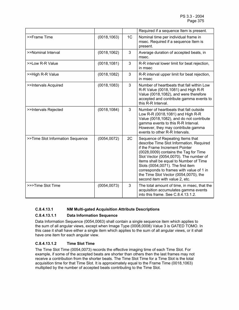
PS 3.3 - 2004 Page 375
Required if a sequence Item is present. >>Frame Time (0018,1063) 1C Nominal time per individual frame in
msec. Required if a sequence Item is present.
>>Nominal Interval (0018,1062) 3 Average duration of accepted beats, in msec.
>>Low R-R Value (0018,1081) 3 R-R interval lower limit for beat rejection, in msec
>>High R-R Value (0018,1082) 3 R-R interval upper limit for beat rejection, in msec
>>Intervals Acquired (0018,1083) 3 Number of heartbeats that fall within Low R-R Value (0018,1081) and High R-R Value (0018,1082), and were therefore accepted and contribute gamma events to this R-R Interval.
>>Intervals Rejected (0018,1084) 3 Number of heartbeats that fall outside Low R-R (0018,1081) and High R-R Value (0018,1082), and do not contribute gamma events to this R-R Interval. However, they may contribute gamma events to other R-R Intervals.
>>Time Slot Information Sequence (0054,0072) 2C Sequence of Repeating Items that describe Time Slot Information. Required if the Frame Increment Pointer (0028,0009) contains the Tag for Time Slot Vector (0054,0070). The number of items shall be equal to Number of Time Slots (0054,0071). The first item corresponds to frames with value of 1 in the Time Slot Vector (0054,0070), the second item with value 2, etc.
>>>Time Slot Time (0054,0073) 3 The total amount of time, in msec, that the acquisition accumulates gamma events into this frame. See C.8.4.13.1.2.
C.8.4.13.1 NM Multi-gated Acquisition Attribute Descriptions C.8.4.13.1.1 Data Information Sequence Data Information Sequence (0054,0063) shall contain a single sequence item which applies to the sum of all angular views, except when Image Type (0008,0008) Value 3 is GATED TOMO. In this case it shall have either a single item which applies to the sum of all angular views, or it shall have one item for each angular view.
C.8.4.13.1.2 Time Slot Time The Time Slot Time (0054,0073) records the effective imaging time of each Time Slot. For example, if some of the accepted beats are shorter than others then the last frames may not receive a contribution from the shorter beats. The Time Slot Time for a Time Slot is the total acquisition time for that Time Slot. It is approximately equal to the Frame Time (0018,1063) multiplied by the number of accepted beats contributing to the Time Slot.

PS 3.3 - 2004 Page 376
C.8.4.14 NM Phase Module Table C.8-14 contains Attributes that describe dynamic phases of a dynamic acquisition image performed on the patient. This module is present only when Image Type (0008,0008), Value 3, is equal to DYNAMIC. A phase is defined as a collection of frames in which the acquisition time per frame and the time delay between frames remains constant. A new phase shall be defined whenever there is a change in the time between frames, the acquisition time per frame, or the position of the patient relative to the detector.
Table C.8-14 NM PHASE MODULE ATTRIBUTES
Attribute Name Tag Type Attribute Description Phase Information Sequence (0054,0032) 2C Sequence of Repeating Items that
describes each dynamic phase. Required if the Frame Increment Pointer (0028,0009) contains the Tag for Phase Vector (0054,0030). The number of items shall be equal to Number of Phases (0054,0031). The first item corresponds to frames with value of 1 in the Phase Vector (0054,0030), the second item with value 2, etc.
>Phase Delay (0054,0036) 1C Time paused between the last frame of the previous phase and the first frame of this phase, in msec. Required if a sequence Item is present.
>Actual Frame Duration (0018,1242) 1C Nominal time of acquisition per individual frame, in msec. Required if a sequence Item is present.
>Pause Between Frames (0054,0038) 1C Time paused between each frame of this phase (in msec). Required if a sequence Item is present.
>Number of Frames in Phase (0054,0033) 1C Number of frames in this phase. Required if a sequence Item is present.
>Trigger Vector (0054,0210) 3 An array of trigger times when gating information is acquired simultaneously with the dynamic image data. See Section C.8.4.14.1.1 for further explanation.
>Number of Triggers in Phase (0054,0211) 1C The number of entries in the Trigger Vector (0054,0210) for this phase. Required if Trigger Vector (0054,0210) is present.
>Phase Description (0054,0039) 3 Description of this phase of the Dynamic image. Defined Terms: FLOW WASHOUT UPTAKE EMPTYING EXCRETION

PS 3.3 - 2004 Page 377
C.8.4.14.1 NM Phase Module Attributes Description C.8.4.14.1.1 Trigger Vector Trigger Vector (0054,0210) is an array containing a list of the inter-trigger interval times in milliseconds in the order in which they were acquired, with the first being measured from the start time of the first frame of the image data in the Phase. If this element is used, the start times are required to be the same so that a mathematical correlation can be made between trigger times and frame start times.
C.8.4.15 NM Reconstruction Module Table C.8-15 contains Attributes that describe Nuclear Medicine reconstructed volumes. Reconstructed volumes are created by applying a transformation (reconstruction) process to the acquired TOMO frames. This module is present only when the Image Type (0008,0008), Value 3, is equal to RECON TOMO or RECON GATED TOMO.
Table C.8-15 NM RECONSTRUCTION MODULE ATTRIBUTES
Attribute Name Tag Type Attribute Description Spacing Between Slices (0018,0088) 2 Spacing between slices, in mm,
measured from center-to-center of each slice along the normal to the first image. The sign of the Spacing Between Slices (0018,0088) determines the direction of stacking. The normal is determined by the cross product of the direction cosines of the first row and first column of the first frame, such that a positive spacing indicates slices are stacked behind the first slice and a negative spacing indicates slices are stacked in front of the first slice. See Image Orientation (0020,0037) in the NM Detector module.
Reconstruction Diameter (0018,1100) 3 Diameter, in mm, of the region from within which the data was used in creating the reconstruction of the image. Data may exist outside this region and portions of the patient may exist outside this region.
Convolution Kernel (0018,1210) 3 A label describing the convolution kernel or algorithm used to reconstruct the data.
Slice Thickness (0018,0050) 2 Nominal slice thickness, in mm. Slice Location (0020,1041) 3 Relative position of exposure expressed
in mm. See C.7.6.2.1.2 for further explanation.
Slice Progression Direction (0054,0500) 3 Describes the anatomical direction that slices are progressing as the slices are considered in order (as defined by the Slice Vector (0054,0080)). Meaningful only for cardiac images. When View Code Sequence (0054,0220) indicates a short axis view, then Enumerated Values are: APEX_TO_BASE

PS 3.3 - 2004 Page 378
BASE_TO_APEX

PS 3.3 - 2004 Page 379
C.8.5 Ultrasound Modules This Section describes Ultrasound Frame of Reference and Image Modules. These Modules contain Attributes that are specific to Ultrasound images.
C.8.5.1 US Frame of Reference Module (Retired) Section C.8.4.1 was defined in a previous version of the DICOM Standard. The Section is now retired.
C.8.5.2 US Region Calibration (Retired) Section C.8.4.2 was defined in a previous version of the DICOM Standard. The Section is now retired.
C.8.5.3 US Image Module (Retired) Section C.8.4.3 was defined in a previous version of the DICOM Standard. The Section is now retired.
C.8.5.4 US Frame of Reference Module Section C.8.5.4 was defined in a previous version of the DICOM Standard. The Section is now retired. See PS 3.3 2003.
C.8.5.5 US Region Calibration Module The US Region Calibration Module has been introduced into the ultrasound IOD to provide access to the full range of data that may be present in a single US image. US images often contain multiple regions that have independent data regions, e.g. quad screen loops that may have different calibration information. The data presented in the various regions of a US image can represent a multiplicity of physical parameters, e.g., spatial distance, blood velocity, time, volume, etc., and these are often contained in the value of the pixel itself. It is therefore imperative that physical information be available for the various regions of a single region independent of each other.
Table C.8-17 contains IOD Attributes that describe an ultrasound region calibration.
Table C.8-17 US REGION CALIBRATION MODULE ATTRIBUTES
Attribute Name Tag Type Attribute Description Sequence of Ultrasound Regions (0018,6011) 1 Defines a sequence of Ultrasound
Regions. One or more Items may be included in this Sequence.
>Region Location Min x0 (0018,6018) 1 The bounds of a rectangle specifying the location of the region, x0,y0,x1,y1.
See C.8.5.5.1.14 for further explanation. >Region Location Min y0 (0018,601A) 1 The bounds of a rectangle specifying the
location of the region, x0,y0,x1,y1.
See C.8.5.5.1.14 for further explanation. >Region Location Max x1 (0018,601C) 1 The bounds of a rectangle specifying the
location of the region, x0,y0,x1,y1.
See C.8.5.5.1.14 for further explanation. >Region Location Max y1 (0018,601E) 1 The bounds of a rectangle specifying the
location of the region, x0,y0,x1,y1.

PS 3.3 - 2004 Page 380
See C.8.5.5.1.14 for further explanation. >Physical Units X Direction (0018,6024) 1 The physical units of the dimensions of the
region. See C.8.5.5.1.15 for Enumerated Values.
>Physical Units Y Direction (0018,6026) 1 The physical units of the dimensions of the region. See C.8.5.5.1.15 for Enumerated Values.
>Physical Delta X (0018,602C) 1 The physical value increments per positive X pixel increment. The units are as specified in the Physical Units X Direction (0018,6024). See C.8.5.5.1.17 for further explanation.
>Physical Delta Y (0018,602E) 1 The physical value increments per positive Y pixel increment. The units are as specified in the Physical Units Y Direction (0018,6026). See C.8.5.5.1.17 for further explanation.
>Reference Pixel x0 (0018,6020) 3 This coordinate pair, x0,y0 defines the location of a virtual "reference" pixel. See C.8.5.5.1.16 for further explanation.
>Reference Pixel y0 (0018,6022) 3 This coordinate pair, x0,y0 defines the location of a virtual "reference" pixel. See C.8.5.5.1.16 for further explanation.
>Ref. Pixel Physical Value X (0018,6028) 3 The Physical Value at the reference pixel x location. The units are specified in the Physical Units field.
>Ref. Pixel Physical Value Y (0018,602A) 3 The Physical Value at the reference pixel y location. The units are specified in the Physical Units field.
>Region Spatial Format (0018,6012) 1 The spatial organization of the data within the region. See C.8.5.5.1.1 for Enumerated Values.
>Region Data Type (0018,6014) 1 The type of data within the region. See C.8.5.5.1.2 for Enumerated Values.
>Region Flags (0018,6016) 1 Flags used for special handling of the region. See C.8.5.5.1.3 for Enumerated Values and further explanation.
>Pixel Component Organization (0018,6044) 1C Describes how the components of a pixel can be described. Required if pixel component calibration exists for this region. See C.8.5.5.1.4 for Enumerated Values and further explanation.
>Pixel Component Mask (0018,6046) 1C This value is ANDed with the composite pixel code for each pixel within the region, then shifted right by the number of

PS 3.3 - 2004 Page 381
contiguous least significant zeros in the mask to obtain what will be referred to as the "Shifted Masked Composite Pixel Code" (SMCPC). Required if Pixel Component Organization = Bit aligned. See C.8.5.5.1.5 for further explanation.
>Pixel Component Range Start (0018,6048) 1C Defines the start of the numeric range of values within the composite pixel where calibration is to be defined by the "pixel physical calibration table". To be used only when ranges are used to describe the portion of the composite pixel. Required if Pixel Component Organization = Ranges.
>Pixel Component Range Stop (0018,604A) 1C Defines the stop of the numeric range of values within the composite pixel where calibration is to be defined by the "pixel physical calibration table". To be used only when ranges are used to describe the portion of the composite pixel. Required if Pixel Component Organization = Ranges.
>Pixel Component Physical Units
(0018,604C) 1C The physical units to be applied to the pixel component. Required if Pixel Component Organization exists. See C.8.5.5.1.6 for further explanation.
>Pixel Component Data Type (0018,604E) 1C The type of data for the pixel component. Required if Pixel Component Organization exists. See C.8.5.5.1.7 for further explanation.
>Number of Table Break Points (0018,6050) 1C The number of break point coordinate pairs used to describe a piece wise linear curve. Required if Pixel Component Organization equals 0 or 1. Otherwise not used. See C.8.5.5.1.8 for further explanation.
>Table of X Break Points (0018,6052) 1C An array of X values used to create the piece wise linear curve. Required if Pixel Component Organization equals 0 or 1. Otherwise not used. See C.8.5.5.1.9 for further explanation.
>Table of Y Break Points (0018,6054) 1C An array of Y values used to create the piece wise linear curve. Required if Pixel Component Organization equals 0 or 1. Otherwise not used. See C.8.5.5.1.9 for further explanation.
>Number of Table Entries (0018,6056) 1C The number of entries in the Table of Pixel

PS 3.3 - 2004 Page 382
Values. Required if the Pixel Component Organization equals 2. Otherwise not used. See C.8.5.5.1.11 for further explanation.
>Table of Pixel Values (0018,6058) 1C A table of Pixel Values used in conjunction with the Table of Parameter Values to provide a mapping from Pixel Value to Parameter Value. Required if the Pixel Component Organization equals 2. Otherwise not used. See C.8.5.5.1.12 for further explanation.
>Table of Parameter Values (0018,605A) 1C A table of Parameter Values used in conjunction with the Table of Pixel Values to provide a mapping from Pixel Value to Parameter Value. Required if the Pixel Component Organization equals 2. Otherwise not used. See C.8.5.5.1.13 for further explanation
>Tranducer Frequency (0018,6030) 3 The manufacturer defined description of center frequency of the interrogating ultrasound energy. The units are kilohertz.
>Pulse Repetition Frequency (0018,6032) 3 The ultrasound pulse repetition frequency, as defined by the manufacturer, used to collect data in the region. The units are in hertz.
>Doppler Correction Angle (0018,6034) 3 The Doppler correction angle. The units are degrees.
>Steering Angle (0018,6036) 3 The steering angle, as defined by the manufacturer, used for a steered 2D image. The units are degrees.
>Doppler Sample Volume X Position (0018,6039) 3 The x displacement, in pixels, from the Reference pixel to the center of the Doppler sample volume.
>Doppler Sample Volume Y Position (0018,603B) 3 The y displacement, in pixels, from the Reference pixel to the center of the Doppler sample volume.
>TM-Line Position x0 (0018,603D) 3 The starting and ending coordinates pairs of the m-line. Where the X0,Y0 are the starting point and X1,Y1 are the end point of the tm-line. See C.8.5.5.1.10 for further explanation.
>TM-Line Position y0 (0018,603F) 3 The starting and ending coordinates pairs of the m-line. Where the X0,Y0 are the starting point and X1,Y1 are the end point of the tm-line.

PS 3.3 - 2004 Page 383
See C.8.5.5.1.10 for further explanation. >TM-Line Position x1 (0018,6041) 3 The starting and ending coordinates pairs
of the m-line. Where the X0,Y0 are the starting point and X1,Y1 are the end point of the tm-line. See C.8.5.5.1.10 for further explanation.
>TM-Line Position y1 (0018,6043) 3 The starting and ending coordinates pairs of the m-line. Where the X0,Y0 are the starting point and X1,Y1 are the end point of the tm-line. See C.8.5.5.1.10 for further explanation.
C.8.5.5.1 US Region Calibration Attribute Descriptions C.8.5.5.1.1 Region Spatial Format Enumerated Values for Region Spatial Format (0018,6012) indicate the spatial organization of the data within the region.
Value Meaning Value Meaning 0000H None or not applicable 0001H 2D(tissue or flow) 0002H M-Mode(tissue or flow) 0003H Spectral(CW or PW Doppler) 0004H Wave form(physiological traces, doppler traces,....) 0005H Graphics
C.8.5.5.1.2 Region Data Type Enumerated Values for Region Data Type (0018,6014) indicate the type of data within the region.
Value Meaning Value Meaning 0000H None or not applicable 0001H Tissue 0002H Color Flow 0003H PW Spectral Doppler 0004H CW Spectral Doppler 0005H Doppler Mean Trace 0006H Doppler Mode Trace 0007H Doppler Max Trace 0008H Volume Trace 0009H d(volume)/dt Trace 000AH ECG Trace 000BH Pulse Trace 000CH Phonocardiogram Trace 000DH Gray bar 000EH Color bar 000FH Integrated Backscatter 0010H Area Trace 0011H d(area)/dt 0012H Other Physiological (Amplitude vs. Time) input
C.8.5.5.1.3 Region Flags Region Flags (0018,6016) specify characteristics of US Regions.
Bit 0 of the Region Flags specifies the relative priority of the pixel component calibration specified by an US Region in the case where the US Region intersects with other US Regions. The calibration supplied by one or more of the regions may not be valid in the area that they intersect. Enumerated Values for Bit 0 (lsb):

PS 3.3 - 2004 Page 384
1 = Region pixels are low priority 0 = Region pixels are high priority
A high priority region overwrites data of a low priority region when they overlap, thus invalidating any pixel component calibration specified for a low priority region. pixel component calibration of overlapping regions of the same priority is indeterminate where they overlap. Figure C.8-6 shows an example of intersecting regions.
Region A
Region B
Region C
+
+
+
Point Z
Point Y
Point X
Figure C.8-6 Intersecting Spatial Format Regions and Overlapping Measurement
In this example, Region B is Color Flow while Region A is Tissue Echo. If Region B Color Flow values share the same bit planes as Region A Tissue Echo values, then it is indeterminate whether a pixel in this region is a Color Flow pixel or a Tissue Echo pixel. Since the pixels of the Color Flow region overwrite those of the Tissue Echo region, the Region Flag of the Tissue Echo region is assigned low priority and the Region Flag of the color region is assigned high priority. This means that if both the Tissue Echo and Color Flow regions define pixel component calibration that only the calibration specified by the Color Flow region can be applied to the pixel data value at Point X.
The measurement in Figure C.8-6 is a line between Point Y and Point Z. Both points are in Region A so the distance between them can be calculated using the Region A scaling (assuming that Region A defines both the Physical Units X Direction and Y Direction as being cm). If the points are in Region B, and hence also in Region A, it is still possible to calculate the distance because the region scaling is identical in both regions. The lower priority of Region B only applies to its pixel component calibration, not its X and Y direction scaling.
Enumerated Values for Bit 1 Scaling Protection:

PS 3.3 - 2004 Page 385
1 = Protected 0 = Not Protected
Ultrasound systems should set this to 1 if the image is scaled automatically by the ultrasound system. If the image is frame-grabbed and scaling is not available then it should be set to 0. If the region is protected, the region can not be manually rescaled. That is the data defined by the region calibration Module can not be overridden by a reader of that image.
Enumerated Values for Bit 2 Doppler Scale Type:
1 = Frequency 0 = Velocity
Valid for PW and CW regions only. Indicates which type of Doppler scale is used.
Enumerated Values for Bit 3-4 Scrolling Region:
00 = Unspecified 01 = Scrolling 10 = Sweeping 11 = Sweeping then Scrolling
Bit 5-31 Reserved for future use, shall be set to zero.
C.8.5.5.1.4 Pixel Component Organization Pixel Component Organization (0018,6044) provides an Enumerated Value describing how the components of a pixel can be described. The absence of this data element means that pixel component calibration does not exist for this region. Where:
0 = Bit aligned positions 1 = Ranges 2 = Table look up
Other values reserved for future use.
Pixel Component Organization defines the way in which the composite pixel values are mapped into real world values with physical units, as illustrated in Figure C.8-7.

PS 3.3 - 2004 Page 386
Region with ‘Bit Aligned’ Pixel Component Organization
Composite Pixel
Pixel Component
Mask (0018,6046)
Value, Unit 0-n
Real World Value
Tables of X & Y Break Points (0018,6052) (0018,6054)
Region with ‘Ranges’ Pixel Component Organization
Composite Pixel
If Within Range Value, Unit
0-n Real World Value
Tables of X & Y Break Points (0018,6052) (0018,6054)
Region with ‘Table Look Up’ Pixel Component Organization
Composite Pixel Value, Unit
0-n Real World Value
Table of Pixel Values (0018,6058) Table of Parameter Values
(0018,605A)
Figure C.8-7 Pixel Component Calibration
An example of Component Calibration for an ultrasound image is shown in Figure C.8-8.
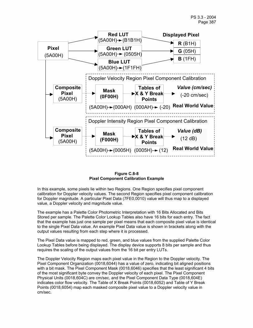
PS 3.3 - 2004 Page 387
Pixel
Red LUT
Green LUT
Blue LUT
Displayed Pixel
R (B1H) G (05H) B (1FH)
Doppler Velocity Region Pixel Component Calibration
Tables of X & Y Break
Points
Mask(0F00H)
Value (cm/sec)
Real World Value
Composite Pixel
Doppler Intensity Region Pixel Component Calibration
Mask(F000H)
Value (dB)
Real World Value
Tables of X & Y Break
Points
Composite Pixel
(5A00H)
(5A00H) (B1B1H)
(5A00H) (0505H)
(5A00H) (1F1FH)
(5A00H)
(5A00H)
(5A00H) (000AH) (000AH) (-20)
(-20 cm/sec)
(5A00H) (0005H) (0005H) (12)
(12 dB)
Figure C.8-8 Pixel Component Calibration Example
In this example, some pixels lie within two Regions. One Region specifies pixel component calibration for Doppler velocity values. The second Region specifies pixel component calibration for Doppler magnitude. A particular Pixel Data (7FE0,0010) value will thus map to a displayed value, a Doppler velocity and magnitude value.
The example has a Palette Color Photometric Interpretation with 16 Bits Allocated and Bits Stored per sample. The Palette Color Lookup Tables also have 16 bits for each entry. The fact that the example has just one sample per pixel means that each composite pixel value is identical to the single Pixel Data value. An example Pixel Data value is shown in brackets along with the output values resulting from each step where it is processed.
The Pixel Data value is mapped to red, green, and blue values from the supplied Palette Color Lookup Tables before being displayed. The display device supports 8 bits per sample and thus requires the scaling of the output values from the 16 bit per entry LUTs.
The Doppler Velocity Region maps each pixel value in the Region to the Doppler velocity. The Pixel Component Organization (0018,6044) has a value of zero, indicating bit aligned positions with a bit mask. The Pixel Component Mask (0018,6046) specifies that the least significant 4 bits of the most significant byte convey the Doppler velocity of each pixel. The Pixel Component Physical Units (0018,604C) are cm/sec, and the Pixel Component Data Type (0018,604E) indicates color flow velocity. The Table of X Break Points (0018,6052) and Table of Y Break Points (0018,6054) map each masked composite pixel value to a Doppler velocity value in cm/sec.

PS 3.3 - 2004 Page 388
The Doppler Magnitude Region maps each pixel value in the Region to the Doppler magnitude. The Pixel Component Organization (0018,6044) has a value of zero, indicating bit aligned positions with a bit mask. The Pixel Component Mask (0018,6046) specifies that the most significant 4 bits of the most significant byte convey the Doppler magnitude of each pixel. The Pixel Component Physical Units (0018,604C) is set to dB, and the Pixel Component Data Type (0018,604E) indicates color flow magnitude. The Table of X Break Points (0018,6052) and Table of Y Break Points (0018,6054) map each masked composite pixel value to a Doppler magnitude value in dB.
C.8.5.5.1.5 Pixel Component Mask Pixel Component Mask (0018,6046) is ANDed with the Composite Pixel Code (see Section C.7.6.3.1.1) for each pixel within the region, then shifted right by the number of contiguous least significant zeros in the mask to obtain what will be referred to as the "Shifted Masked Composite Pixel Code".
The mask will most likely (but not necessarily) contain a block of contiguous ones, surrounded by leading and trailing zeros. The purpose of this mask is to keep only those bits within the composite pixel code that pertain to the region. It is to be used only when Pixel Organization is bit aligned positions.
C.8.5.5.1.6 Pixel Component Physical Units For Pixel Component Physical Units (0018,604C), the Enumerated Values describing the physical units to be applied to the pixel component are:
Value Meaning Value Meaning 0000H None or not applicable 0001H Percent 0002H dB 0003H cm 0004H seconds 0005H hertz(seconds-1) 0006H dB/seconds 0007H cm/sec
0008H cm2 0009H cm2/sec
000AH cm3 000BH cm3/sec 000CH degrees
C.8.5.5.1.7 Pixel Component Data Type For Pixel Component Data Type (0018,604E), the Enumerated Values indicating the type of data for the pixel component are:
Value Meaning Value Meaning 0000H None or not applicable 0001H Tissue 0002H Spectral doppler 0003H Color Flow Velocity 0004H Color Flow Variance 0005H Color Flow Intensity 0006H Gray bar 0007H Color bar 0008H Integrated Backscatter 0009H Computed Border
C.8.5.5.1.8 Number of Table Break Points The Number of Table Break Points (0018,6050) gives the number of entries in each of two tables: the Table of X Break Points (0018,6052) and Table of Y Break Points (0018,6054). These tables

PS 3.3 - 2004 Page 389
are used to designate a curve mapping the value of a pixel component to its actual physical value, as described in Section C.8.5.5.1.9.
C.8.5.5.1.9 Table of X Break Points and Table of Y Break Points Table of X Break Points (0018,6052) and Table of Y Break Points (0018,6054) are individual arrays of coordinates which interpreted together are used to create a piecewise linear curve. Each X value from the Table of X Break Points is matched with the corresponding Y value from the Table of Y Break Points yielding an (X,Y) coordinate. The set of (X,Y) coordinates describes a piecewise linear curve mapping the value of a pixel component to its actual physical value (in units defined in Pixel Component Physical Units data element (0018,604C) ).
The X direction on the curve has no units, and represents actual pixel component values. If the Pixel Component Organization (0018,6044) is "Bit aligned positions", and the width of the Pixel Component Mask is n bits then the X coordinates are in the range 0 through 2n -1. If the Pixel Component Organization is Ranges, then the X coordinates are in the range 0 through 2 number of bits in the composite pixel - 1.
Note: The X value is NOT relative to the Pixel Component Range Start (0018,6048). Not all possible X values in the range need be covered by the curve.
For any pixel component value in the range of the curve described by this table, the corresponding Y value is the actual physical value for that pixel, in units specified in the Pixel Component Physical Units data element (0018,604C). If the pixel component value is NOT within the range of specified X values for the curve, then no pixel calibration is defined by this region. It may be possible for pixel calibration to be defined by other spatial regions intersecting this one.
C.8.5.5.1.10 TM-Line Position X0 , TM-Line Position Y0,
TM-Line Position X1 ,TM-Line Position Y1
The TM-Line Position X0 (0018,603D) and TM-Line Position Y0 (0018,603F) are the coordinates of the starting point and TM-Line Position X1 (0018,6041), TM-Line Position Y1 (0018,6043) are the coordinates of the end point of the TM-line. The coordinate is defined as the displacement, in pixels, from the Reference pixel. Typically used for M-mode line and CW Doppler.
C.8.5.5.1.11 Number of Table Entries The Number of Table Entries (0018,6056) gives the number of entries in the Table of Pixel Values. The number of entries in the Table of Parameter Values is also equal to this number. Pixel Value and Parameter Value tables are used to assign Parameter values to pixels. A pixel is calibrated by finding an entry in the Pixel Value Table that matches its Composite Pixel Code (see Section C.7.6.3.1.1). The offset of this entry is used as an index into the Parameter Value Table. The Parameter value entry at this offset gives the Parameter Value of the Pixel.
Note: If a Composite Pixel Code has no matching value in the Pixel Value Table then there is no unambiguous way to determine the corresponding Parameter Value. A method may exist to determine a valid Parameter Value but the specification of such a method is outside the scope of the DICOM standard. No assumption should be made that linear interpolation will produce a valid result.
C.8.5.5.1.12 Table of Pixel Values This is a table of unique Pixel Codes (0018,6058). The number of entries in the table is given by Number of Table Entries (0018,6056).
C.8.5.5.1.13 Table of Parameter Values This is a table of parameter values (0018,605A). The number of table entries is given by Number of Table Entries and the physical units are given by Pixel Component Physical Units
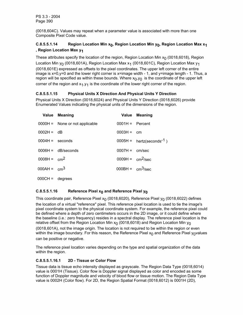
PS 3.3 - 2004 Page 390
(0018,604C). Values may repeat when a parameter value is associated with more than one Composite Pixel Code value.
C.8.5.5.1.14 Region Location Min x0, Region Location Min y0, Region Location Max x1 , Region Location Max y1 These attributes specify the location of the region, Region Location Min x0 (0018,6018), Region Location Min y0 (0018,601A), Region Location Max x1 (0018,601C), Region Location Max y1 (0018,601E) expressed as offsets to the pixel coordinates. The upper left corner of the entire image is x=0,y=0 and the lower right corner is x=image width - 1, and y=image length - 1. Thus, a region will be specified as within these bounds. Where x0,y0 is the coordinate of the upper left corner of the region and x1,y1 is the coordinate of the lower right corner of the region.
C.8.5.5.1.15 Physical Units X Direction And Physical Units Y Direction Physical Units X Direction (0018,6024) and Physical Units Y Direction (0018,6026) provide Enumerated Values indicating the physical units of the dimensions of the region.
Value Meaning Value Meaning
0000H = None or not applicable 0001H = Percent
0002H = dB 0003H = cm
0004H = seconds 0005H = hertz(seconds-1 )
0006H = dB/seconds 0007H = cm/sec
0008H = cm2 0009H = cm2/sec
000AH = cm3 000BH = cm3/sec
000CH = degrees C.8.5.5.1.16 Reference Pixel x0 and Reference Pixel y0 This coordinate pair, Reference Pixel x0 (0018,6020), Reference Pixel y0 (0018,6022) defines the location of a virtual "reference" pixel. This reference pixel location is used to tie the image's pixel coordinate system to the physical coordinate system. For example, the reference pixel could be defined where a depth of zero centimeters occurs in the 2D image, or it could define where the baseline (i.e.: zero frequency) resides in a spectral display. The reference pixel location is the relative offset from the Region Location Min x0 (0018,6018) and Region Location Min y0 (0018,601A), not the image origin. The location is not required to be within the region or even within the image boundary. For this reason, the Reference Pixel x0 and Reference Pixel y0values can be positive or negative.
The reference pixel location varies depending on the type and spatial organization of the data within the region.
C.8.5.5.1.16.1 2D - Tissue or Color Flow Tissue data is tissue echo intensity displayed as grayscale. The Region Data Type (0018,6014) value is 0001H (Tissue). Color flow is Doppler signal displayed as color and encoded as some function of Doppler magnitude and velocity of blood flow or tissue motion. The Region Data Type value is 0002H (Color flow). For 2D, the Region Spatial Format (0018,6012) is 0001H (2D),

PS 3.3 - 2004 Page 391
meaning that the region is a tomographic image. For such 2D regions the reference pixel location is typically at the center of the transducer face on the tissue-transducer interface (skin line).
Figure C.8-1 shows 2D attribute values of reference pixel location along with Region Location Min and Region Location Max. for 2D–Tissue and 2D–Color Flow Regions:
Transducer
2D - Tissue Region
2D - Color Flow Region
2D - Tissue Reference Pixel
x0, y0 = (164, -120)
2D - Tissue Region Location Min
x0, y0 = (162,60)
2D - Tissue Region Location Max
x1, y1 = (476,414)
Pixel coordinate system
(0,0)
(639,479)
2D - Color Flow Reference Pixel
x0, y0 = (124, -160)
x0, y0 = (202,100)
2D - Color Flow Region Location Min
2D - Color Flow Region Location Max
x1, y1 = (436,345)
Screen origin offset
Figure C.8-1 2D Regions with Reference Pixel
Both the 2D regions–Tissue and Color Flow–share the same physical location at the skin line but the reference pixel location values (Reference Pixel x0 and Reference Pixel y0) are relative to their respective region origins at the skin line.
C.8.5.5.1.16.2 Spectral - CW or PW Doppler or Doppler Trace Spectral Doppler is the time varying magnitude of Doppler signal as function of frequency. Region Data Type (0018,6014) value is 0003H (pulsed wave Doppler) or 0004H (continuous wave Doppler). Spectral Doppler regions display the magnitude of Doppler signal with frequency or velocity as the vertical dimension and time as the horizontal dimension. Spectral Doppler regions have a Region Spatial Format (0018,6012) of 0003H (Spectral). The time dimension for

PS 3.3 - 2004 Page 392
the Region Spatial Format displays horizontally with data scrolling toward the left or sweeping toward the right. The reference pixel location is the pixel in the frame where:
• the time is the time of frame capture (i.e. the time origin for the frame)
• and on the Doppler Baseline (i.e. where the velocity and frequency are zero).
Figure C.8-2 shows an example of reference pixel locations in an image with both a Tissue and a scrolling Spectral (CW or PW Doppler) Region. The user adjusts the depth and position of the Doppler sample volume. The system annotates the sample volume position on the 2D region and specifies the location in Doppler Sample Volume X Position (0018,6039) and Doppler Sample Volume Y Position (0018,603B).
2D - Tissue Region
2D - Color Flow Region
Transducer
2D - Tissue Reference Pixel x0, y0 = (108, 0)
Spectral Region (CW or PW Doppler) Spectral Region Reference Pixel x0, y0 = (642, 162)
Doppler Baseline
Doppler SampleVolume Position
(0,0)
(799,599)
2D - Tissue Region Location Min
x0, y0 = (290,30)
Spectral Doppler Region Location Min
x0, y0 = (64,268)
Pixel coordinate system
2D - Tissue Region Location Max
x1, y1 = (506,252)
Spectral Doppler Region Location Max
x1, y1 = (706,506)
2D - Color Flow Region Location Min
x0, y0 = (320,90) 2D - Color Flow Region Location Max
x1, y1 = (480,180)
2D - Color Flow Reference Pixel x0, y0 = (80, -60)
Figure C.8-2 2D & Doppler Regions with Reference Pixel
The scrolling Spectral Region reference pixel location specifies the horizontal location at the time of the current image frame. Data to the left of this location in the Spectral Region was acquired in the past. Because time increases to the right, the Physical Delta X (0018,602C) for this Region is positive. To specify the location of the most recent data the Reference Pixel x0 specifies the time of acquisition, and the Ref. Pixel Physical Value X (0018,6028) specifies the reference time to be

PS 3.3 - 2004 Page 393
zero. The Physical Units X Direction (0018,6024) is seconds. For an explanation of how to handle sweeping regions refer to C.8.5.5.1.16.7 Treatment of Sweeping Regions.
The Ref. Pixel Physical Value Y (0018,602A) value specifies the baseline where velocity or frequency are zero. Typically spectral Doppler regions display positive velocity (cm/Sec) or frequency shift (Hz) above the baseline. This indicates flow toward the transducer face. Negative velocity or frequency information is displayed below the baseline. This indicates flow away from the transducer face. The Physical Delta Y (0018,602E) value is therefore negative because vertical coordinates increment downward.
C.8.5.5.1.16.3 M-Mode - Tissue or Color Flow M-Mode is tissue or color flow with a Region Spatial Format (0018,6012) of 0002H (M-mode). The vertical reference pixel location is the transducer face.
The horizontal reference pixel location is the pixel in the frame where:
• the time is the time of frame capture (i.e. the time origin for the frame)
• and zero depth from the transducer face
Figure C.8-3 shows an example of reference pixel locations for 2D Tissue and M-Mode Regions within the same image frame. The system annotates the sample line position on the 2D tissue region and specifies its position with the TM-Line Position attributes (0018,603D), (0018,603F), (0018,6041), and (0018,6043).

PS 3.3 - 2004 Page 394
TM-Line
Pixel Coordinate System
2D - Tissue Region
M-Mode - Tissue Region
M-Mode - Tissue Reference Pixel
x0, y0 = (552,-165)
2D - Tissue Reference Pixel x0, y0 = (135,18)
(0,0)
(639,479)
2D – Tissue Region Location Min
x0, y0 = (210,23)
2D – Tissue Region Location Max
x1, y1 = (473,226) M-Mode – Tissue Region Location Min
x0, y0 = (58,245)
M-Mode – Tissue Region Location Max
x1, y1 = (610,450)
Transducer
Figure C.8-3 2D & M-Mode Regions with Reference Pixel Example
The physical length of the TM-Line corresponds directly to the physical height of the M-Mode Region. The M-Mode region’s Reference Pixel y0 can be used to calculate the depth of the M-Mode region and facilitate depth measurements. In this example the M-Mode Region Reference Pixel y0 has a negative value corresponding to the distance between the face of the ultrasound probe and the TM-Line starting point. Note that the negative offset in pixel units is determined using the pixel height-width scaling of the M-Mode - Tissue Region as this could differ from the scaling of the 2D – Tissue Region (as it does in this example).
C.8.5.5.1.16.4 Waveform - ECG, Phonocardiogram and Pulse Traces Waveforms are traces with a Region Spatial Format (0018,6012) value of 0004H (Waveform). The Reference Pixel x0 (0018,6020) specifies the time origin as the time of frame capture. There is typically no baseline position for ECG traces; the Reference Pixel y0 (0018,6022) is arbitrary.
Figure C.8-4 shows an example of reference pixel location for 2D Tissue, M-Mode, and ECG Waveform Regions within the same image frame:
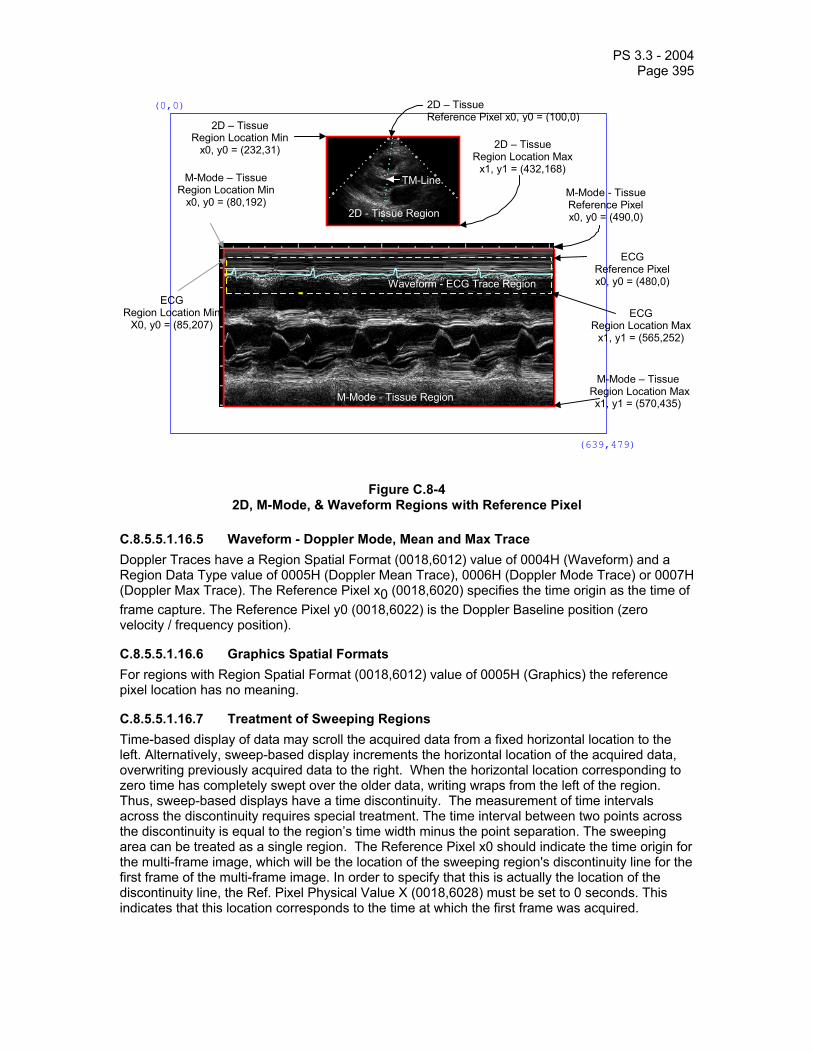
PS 3.3 - 2004 Page 395
2D - Tissue Region
M-Mode - Tissue Region
Waveform - ECG Trace Region
(0,0)
(639,479)
2D – Tissue Reference Pixel x0, y0 = (100,0)
M-Mode - Tissue Reference Pixel x0, y0 = (490,0) 2D - Tissue Region
TM-Line
2D – Tissue Region Location Min
x0, y0 = (232,31)
ECG Reference Pixel x0, y0 = (480,0)
2D – Tissue Region Location Max
x1, y1 = (432,168)
M-Mode – Tissue Region Location Max
x1, y1 = (570,435)
ECG Region Location Max
x1, y1 = (565,252)
M-Mode – Tissue Region Location Min
x0, y0 = (80,192)
ECG Region Location Min
X0, y0 = (85,207)
Figure C.8-4 2D, M-Mode, & Waveform Regions with Reference Pixel
C.8.5.5.1.16.5 Waveform - Doppler Mode, Mean and Max Trace Doppler Traces have a Region Spatial Format (0018,6012) value of 0004H (Waveform) and a Region Data Type value of 0005H (Doppler Mean Trace), 0006H (Doppler Mode Trace) or 0007H (Doppler Max Trace). The Reference Pixel x0 (0018,6020) specifies the time origin as the time of frame capture. The Reference Pixel y0 (0018,6022) is the Doppler Baseline position (zero velocity / frequency position).
C.8.5.5.1.16.6 Graphics Spatial Formats For regions with Region Spatial Format (0018,6012) value of 0005H (Graphics) the reference pixel location has no meaning.
C.8.5.5.1.16.7 Treatment of Sweeping Regions Time-based display of data may scroll the acquired data from a fixed horizontal location to the left. Alternatively, sweep-based display increments the horizontal location of the acquired data, overwriting previously acquired data to the right. When the horizontal location corresponding to zero time has completely swept over the older data, writing wraps from the left of the region. Thus, sweep-based displays have a time discontinuity. The measurement of time intervals across the discontinuity requires special treatment. The time interval between two points across the discontinuity is equal to the region’s time width minus the point separation. The sweeping area can be treated as a single region. The Reference Pixel x0 should indicate the time origin for the multi-frame image, which will be the location of the sweeping region's discontinuity line for the first frame of the multi-frame image. In order to specify that this is actually the location of the discontinuity line, the Ref. Pixel Physical Value X (0018,6028) must be set to 0 seconds. This indicates that this location corresponds to the time at which the first frame was acquired.

PS 3.3 - 2004 Page 396
It is useful to be able to calculate the location of the discontinuity line for subsequent frames of a multi-frame image. This is necessary if one is to determine whether two points are on opposite sides of the discontinuity line and also to correctly calculate the difference in time between such points. The x-axis location of the discontinuity line, x, for a given frame number, y, can be calculated from the Reference Pixel x0, x0, the Reference Pixel x1, x1, the time offset for frame y, t, (determined from the Frame Time Vector (0018,1065) or Frame Time (0018,1063)) and the Physical Delta X (0018,602C), px, as follows:
x = x0 + modulus( (t / px) / (x1 – x0) )
Alternatively, two regions can be used, one on each side of the time discontinuity. Figure C.8-5 shows the use of two regions. Note that the two region approach is not valid for multi-frame images, as the same region scaling must apply to all the frames.
2D - Tissue Region
M-Mode - Tissue Region
(0,0)
(639,479)
2D – Tissue Region Reference Pixel x0, y0 = (88,0)
Pixel Coordinate System
1st M-Mode – Tissue Reference Pixel x0, y0 = (266,0)
Ref. Pixel Physical Value X, Y = (0,0)
2D - Tissue Region
TM-Line
2D – Tissue Region Location Min
x0, y0 = (232,31) 2D – Tissue
Region Location Max x1, y1 = (408,162)
1st M-Mode – Tissue Region Location Max
x1, y1 = (350,435)
1st M-Mode – Tissue Region Location Min
x0, y0 = (84,196) 2nd M-Mode – Tissue Region Location Min x0, y0 = (362,196)
2nd M-Mode – Tissue Reference Pixel x0, y0 = (188,0)
Ref. Pixel Physical Value X, Y = (-2.3,0)
2nd M-Mode – Tissue Region Location Max
x1, y1 = (550,435)
Figure C.8-5 Sweep Example using Two Regions
The two region approach may also be used in Doppler or physiological sweeping regions.
Time-based display of data may also be a combination of sweeping and scrolling. Sweep-based display is used at the start of acquisition, incrementing the horizontal location of the acquired data from left to right. After the horizontal location corresponding to zero time has completely swept to the right hand limit of the region, writing scrolls to the left from the right hand limit rather than wrapping from the left. A single region should be specified when this combination of behavior is used. The x-axis (zero time) location, x, for a given frame number, y, can be calculated from the Reference Pixel x0, x0, the Reference Pixel x1, x1, the time offset for frame y, t, (determined from the Frame Time Vector (0018,1065) or Frame Time (0018,1063)) and the Physical Delta X, px, as follows:
X = Min ( x0 + (t / px), x1)
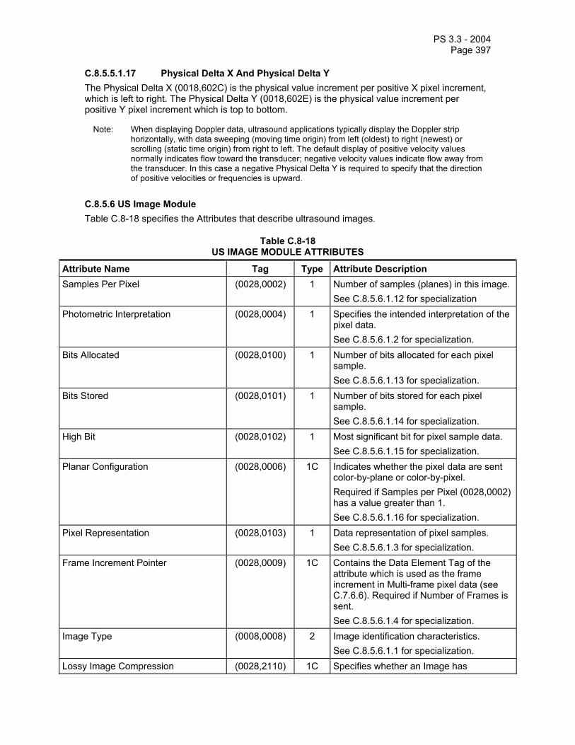
PS 3.3 - 2004 Page 397
C.8.5.5.1.17 Physical Delta X And Physical Delta Y The Physical Delta X (0018,602C) is the physical value increment per positive X pixel increment, which is left to right. The Physical Delta Y (0018,602E) is the physical value increment per positive Y pixel increment which is top to bottom.
Note: When displaying Doppler data, ultrasound applications typically display the Doppler strip horizontally, with data sweeping (moving time origin) from left (oldest) to right (newest) or scrolling (static time origin) from right to left. The default display of positive velocity values normally indicates flow toward the transducer; negative velocity values indicate flow away from the transducer. In this case a negative Physical Delta Y is required to specify that the direction of positive velocities or frequencies is upward.
C.8.5.6 US Image Module Table C.8-18 specifies the Attributes that describe ultrasound images.
Table C.8-18 US IMAGE MODULE ATTRIBUTES
Attribute Name Tag Type Attribute Description Samples Per Pixel (0028,0002) 1 Number of samples (planes) in this image.
See C.8.5.6.1.12 for specialization Photometric Interpretation (0028,0004) 1 Specifies the intended interpretation of the
pixel data. See C.8.5.6.1.2 for specialization.
Bits Allocated (0028,0100) 1 Number of bits allocated for each pixel sample. See C.8.5.6.1.13 for specialization.
Bits Stored (0028,0101) 1 Number of bits stored for each pixel sample. See C.8.5.6.1.14 for specialization.
High Bit (0028,0102) 1 Most significant bit for pixel sample data. See C.8.5.6.1.15 for specialization.
Planar Configuration (0028,0006) 1C Indicates whether the pixel data are sent color-by-plane or color-by-pixel. Required if Samples per Pixel (0028,0002) has a value greater than 1. See C.8.5.6.1.16 for specialization.
Pixel Representation (0028,0103) 1 Data representation of pixel samples. See C.8.5.6.1.3 for specialization.
Frame Increment Pointer (0028,0009) 1C Contains the Data Element Tag of the attribute which is used as the frame increment in Multi-frame pixel data (see C.7.6.6). Required if Number of Frames is sent. See C.8.5.6.1.4 for specialization.
Image Type (0008,0008) 2 Image identification characteristics. See C.8.5.6.1.1 for specialization.
Lossy Image Compression (0028,2110) 1C Specifies whether an Image has

PS 3.3 - 2004 Page 398
undergone lossy compression. Enumerated Values:
00 = Image has NOT been subjected to lossy compression.
01 = Image has been subjected to lossy compression.
See C.7.6.1.1.5 Required if Lossy Compression has been performed on the Image.
Number of Stages (0008,2124) 2C Number of Stages in this protocol. Required if image was acquired in a Staged protocol.
Number of Views in Stage (0008,212A) 2C Number of views in this Stage. Required if image was acquired in a Staged protocol.
R Wave Time Vector (0018,6060) 3 The time offset(s) of the reported R Wave peaks, each relative to the time of the start of the acquisition of the first frame in msec. Multi-valued, with one value per reported R Wave.
Ultrasound Color Data Present (0028,0014) 3 This element indicates if any ultrasound color data is present in an image. Enumerated Values:
00 = Ultrasound color data not present in image
01 = Ultrasound color data is present in image.
See C.8.5.6.10 Referenced Overlay Sequence (0008,1130) 3 A Sequence which provides reference to a
set of SOP Class/Instance pairs which are related independent Overlays. Uniquely identifies Overlays significantly related to this Image. Zero or more Items may be included in this Sequence.
>Referenced SOP Class UID (0008,1150) 1C Uniquely identifies the referenced SOP Class. Required if Referenced Overlay Sequence (0008,1130) is sent.
>Referenced SOP Instance UID (0008,1155) 1C Uniquely identifies the referenced SOP Instance. Required if Reference Overlay Sequence (0008,1130) is sent.
Referenced Curve Sequence (0008,1145) 3 A sequence which provides reference to a set of SOP Class/Instance pairs which are related independent Curves. Uniquely identifies Curves significantly related to this Image.
>Referenced SOP Class UID (0008,1150) 1C Uniquely identifies the referenced SOP Class. Required if Referenced Curve Sequence (0008,1145) is sent.
>Referenced SOP Instance UID (0008,1155) 1C Uniquely identifies the referenced SOP Instance. Required if Reference Curve

PS 3.3 - 2004 Page 399
Sequence (0008,1145) is sent. Stage Name (0008,2120) 3 A Stage is a particular time slice of a
protocol in which a set of images are collected. The names can be free form text. Recommended text for Stress Echo stage names are: PRE-EXERCISE, POST-EXERCISE, PEAK-EXERCISE, RECOVERY, BASELINE, LOW DOSE, PEAK DOSE
Stage Code Sequence (0040,000A) 3 Sequence of items describing the performed Ultrasound Protocol Stage(s).
>Include “Code Sequence Macro” Table 8.8-1. Baseline Context ID is 12002. Stage Number (0008,2122) 3 A number that identifies the Stage. Stage
Number starts at one. View Name (0008,2127) 3 A View is a particular combination of the
position and orientation when a set of images are acquired. Images are acquired at the same View in different Stages for the purpose of comparison.
View Number (0008,2128) 3 A number that identifies the View. View Number starts at one.
Number of Event Timers (0008,2129) 3 The number of event timers used at the time of acquisition of a Multi-frame image.
Event Elapsed Time(s) (0008,2130) 3 An array of values associated with each event timer. Units in milliseconds.
Event Timer Name(s) (0008,2132) 3 Name that identifies the event timer. Include 'General Anatomy Optional Macro' Table 10-7 For intravascular ultrasound, DCIDs 3010
and 3015 are specified for the Anatomic Region Sequence and DCID 3019 is specified for the Anatomic Region Modifier Sequence. No other Context IDs are specified.
Transducer Position Sequence (0008,2240) 3 Sequence of one or more Items that identifies the transducer position used in this image. See Section C.8.5.6.1.19.
>Include ‘Code Sequence Macro’ Table 8.8-1 Baseline Context ID is 4. > Transducer Position Modifier Sequence
(0008,2242) 3 Sequence of one or more Items that modifies the primary transducer position of interest in this image. See Section C.8.5.6.1.19.
>>Include ‘Code Sequence Macro’ Table 8.8-1 Baseline Context ID is 5. Transducer Orientation Sequence (0008,2244) 3 Sequence of one or more Items that
identifies the Transducer Orientation used

PS 3.3 - 2004 Page 400
in this image. See Section C.8.5.6.1.20.
>Include ‘Code Sequence Macro’ Table 8.8-1 Baseline Context ID is 6. > Transducer Orientation Modifier Sequence
(0008,2246) 3 Sequence of one or more Items that modifies the primary Transducer Orientation of interest in this image. See Section C.8.5.6.1.20
>>Include ‘Code Sequence Macro’ Table 8.8-1 Baseline Context ID is 7. Acquisition Datetime (0008,002A) 1C The date and time that the acquisition of
data that resulted in this image started. Required if Modality (0008,0060) = IVUS May be present otherwise.
Note: The synchronization of this time with an external clock is specified in the Synchronization Module in Acquisition Time Synchronized (0018,1800).
Trigger Time (0018,1060) 3 Time interval measured in msec from the start of the R-wave to the beginning of data taking
Nominal Interval (0018,1062) 3 Average R-R interval used for these data, in msec
Beat Rejection Flag (0018,1080) 3 Beat length sorting has been applied. Enumerated Values: Y = yes N = no
Low R-R Value (0018,1081) 3 R-R interval low limit for beat rejection, in msec
High R-R Value (0018,1082) 3 R-R interval high limit for beat rejection, in msec
Heart Rate (0018,1088) 3 Beats per minute. IVUS Acquisition (0018,3100) 1C Defined Terms:
MOTOR_PULLBACK MANUAL_PULLBACK SELECTIVE GATED_PULLBACK See C.8.5.6.1.21 Required if Modality (0008,0060) = IVUS
IVUS Pullback Rate (0018,3101) 1C Required if IVUS Acquisition (0018,3100) value is MOTOR_PULLBACK. Specified in units of mm/sec. See C.8.5.6.1.22
IVUS Gated Rate (0018,3102) 1C Required if IVUS Acquisition (0018,3100) value is GATED_PULLBACK. Specified in units of mm/beat. See C.8.5.6.1.23

PS 3.3 - 2004 Page 401
IVUS Pullback Start Frame Number (0018,3103) 1C Required if IVUS Acquisition (0018,3100) value is MOTOR_PULLBACK or GATED_PULLBACK. See C.8.5.6.1.24
IVUS Pullback Stop Frame Number (0018,3104) 1C Required if IVUS Acquisition (0018,3100) value is MOTOR_PULLBACK or GATED_PULLBACK. See C.8.5.6.1.25
Lesion Number (0018,3105) 3 Identifier(s) of the lesion(s) of interest imaged within the current SOP Instance. Each lesion shall have a unique numeric integer identifier within the study. See C.8.5.6.1.26.
Output Power (0018,5000) 3 Manufacturer defined character string description of ultrasound output level(s) used in generating a given image. Data may be expressed in dB, %, W/cm2, etc.
Transducer Data (0018,5010) 3 Manufacturer defined code or description of ultrasound transducer used.
Transducer Type (0018,6031) 3 Defined Terms: SECTOR_PHASED SECTOR_MECH SECTOR_ANNULAR LINEAR CURVED LINEAR SINGLE CRYSTAL SPLIT XTAL CWD IV_PHASED IV_ROT XTAL IV_ROT MIRROR ENDOCAV_PA ENDOCAV_MECH ENDOCAV_CLA ENDOCAV_AA ENDOCAV_LINEAR VECTOR_PHASED
Focus Depth (0018,5012) 3 The depth, from the transducer face, of the manufacturer defined beam focus used for the image, in cm.
Preprocessing Function (0018,5020) 3 Manufacturer defined description of processing of echo information. Data may include code or description of gain (initial, overall, TGC, dynamic range, etc.), preprocessing, postprocessing, Doppler processing parameters, e.g. cutoff filters, etc., as used in generating a given image.
Mechanical Index (0018,5022) 3 See C.8.5.6.1.8 for Description. Bone Thermal Index (0018,5024) 3 See C.8.5.6.1.8 for Description. Cranial Thermal Index (0018,5026) 3 See C.8.5.6.1.8 for Description.

PS 3.3 - 2004 Page 402
Soft Tissue Thermal Index (0018,5027) 3 See C.8.5.6.1.8 for Description. Soft Tissue-focus Thermal Index (0018,5028) 3 See C.8.5.6.1.8 for Description. Soft Tissue-surface Thermal Index (0018,5029) 3 See C.8.5.6.1.8 for Description. Depth of Scan Field (0018,5050) 3 The depth, in mm, from the transducer
face to the deepest point included in the displayed image– the field of view.
Overlay Subtype (60xx,0045) 3 Defined term which identifies the intended purpose of the ROI Overlay Type. See C.8.5.6.1.11 for specialization.
C.8.5.6.1 US Image Attribute Descriptions C.8.5.6.1.1 Image Type For US Images, Image Type (0008,0008) is specified to be Type 2. The Defined Terms for Value 3 are:
ABDOMINAL BREAST CHEST ENDOCAVITARY ENDORECTAL ENDOVAGINAL EPICARDIAL FETAL HEART GYNECOLOGY INTRACARDIAC INTRAOPERATIVE INTRAVASCULAR MUSCULOSKELETAL NEONATAL HEAD OBSTETRICAL OPHTHALMIC PEDIATRIC PELVIC RETROPERITONEAL SCROTAL SMALL PARTS TEE THYROID TRANSCRANIAL TTE US BIOPSY VASCULAR
Value 4 is constructed as a modality bit map to allow for a description of multi-modality displays. In using this bit map, the sum of the values of the various modalities will unambiguously determine the constituent modalities.
0001 = 2D Imaging 0002 = M-Mode 0004 = CW Doppler 0008 = PW Doppler 0010 = Color Doppler 0020 = Color M-Mode 0040 = 3D Rendering 0100 = Color Power Mode
Notes: 1. All Values are hexadecimal encoded as a CS. See PS 3.5. 2. For example, Color Flow with CW spectral Doppler would have a value 4 = 0015. Note that no
assumption should be made in Color Doppler or Color M-Mode regarding underlying B or M-Mode, respectively.
C.8.5.6.1.2 Photometric Interpretation For US Images, Photometric Interpretation (0028,0004) is specified to use the following Defined Terms:
MONOCHROME2 PALETTE COLOR RGB ARGB (retired) YBR_FULL YBR_FULL_422 YBR_PARTIAL_422 YBR_RCT YBR_ICT

PS 3.3 - 2004 Page 403
Note: It is recommended that future implementations should not use ARGB photometric interpretation.
See PS 3.5 for restrictions imposed by compressed Transfer Syntaxes.
C.8.5.6.1.3 Pixel Representation For US Images, Pixel Representation (0028,0103) is specified to use the following Enumerated Value:
0000H = unsigned integer C.8.5.6.1.4 Frame Increment Pointer For US Multi-frame images, the Attribute Frame Increment Pointer (0028,0009) of the Multi-frame Module (see Section C.7.6.6) is specified by the following Defined Terms:
00181063 = sequencing by Frame Time (0018,1063) 00181065 = sequencing by Frame Time Vector (0018,1065)
C.8.5.6.1.5 Retired C.8.5.6.1.6 Retired C.8.5.6.1.7 Retired C.8.5.6.1.8 Mechanical Index, Bone Thermal Index, Cranial Thermal Index, Soft Tissue Thermal Index The thermal and/or mechanical indices, when made available by a manufacturer, are defined according to the Standard for Real-Time Display of Thermal and Mechanical Acoustic Output Indices on Diagnostic Ultrasound Equipment, a voluntary performance standard jointly published by AIUM and NEMA.
C.8.5.6.1.9 Image Transformation Matrix and Image Translation Vector This section was defined in a previous version of the DICOM Standard. The Section is now retired. See PS 3.3 2003.
C.8.5.6.1.10 Ultrasound Color Data Present Note: This data element can be used to indicate if an image contains any Ultrasound color data. For example: Some Ultrasound images may have a Photometric Interpretation equal to RGB
but the image will have no color information if R=G=B for all pixels. For consistency within a particular implementation Monochrome Ultrasound images may be
coded using a color photometric interpretation. In that case inclusion of this data element can significantly speed up processing. Since all components are known to be equal only one need be handled. The enhancements can be significant when compressed Transfer Syntaxes are used.
C.8.5.6.1.11 Overlay Subtype For US Images, Overlay Subtype (60xx,0045) shall use the following Defined Terms:
ACTIVE 2D/BMODE IMAGE AREA = identification of the active area of a 2D/B-mode image.
C.8.5.6.1.12 Samples Per Pixel For US Images, Samples Per Pixel (0028,0002) is specified to use the following values for specific Photometric Interpretations:

PS 3.3 - 2004 Page 404
Table C.8-19 US SAMPLES PER PIXEL
Photometric Interpretation Samples Per Pixel Value MONOCHROME2 1 RGB 3 YBR_FULL 3 YBR_FULL_422 3 YBR_PARTIAL_422 3 YBR_RCT 3 YBR_ICT 3 PALETTE COLOR 1
C.8.5.6.1.13 Bits Allocated For US Images, Bits Allocated (0028,0100) is specified to use the following values for specific Photometric Interpretations:
Table C.8-20 US BITS ALLOCATED
Photometric Interpretation Bits Allocated Value MONOCHROME2 8 RGB 8 YBR_FULL 8 YBR_FULL_422 8 YBR_PARTIAL_422 8 YBR_RCT 8 YBR_ICT 8 PALETTE COLOR 8 - 8 bit palette, or
16 - 16 bit palette
C.8.5.6.1.14 Bits Stored For US Images, Bits Stored (0028,0101) is specified to use the following values for specific Photometric Interpretations:

PS 3.3 - 2004 Page 405
Table C.8-21 US BITS STORED
Photometric Interpretation Bits Stored Value MONOCHROME2 8 RGB 8 YBR_FULL 8 YBR_FULL_422 8 YBR_PARTIAL_422 8 YBR_RCT 8 YBR_ICT 8 PALETTE COLOR 8 - 8 bit palette, or
16 - 16 bit palette
C.8.5.6.1.15 High Bit For US Images, High Bit (0028,0102) is specified to use the following values for specific Photometric Interpretations:
Table C.8-22 US HIGH BIT
Photometric Interpretation High Bit Value MONOCHROME2 7 RGB 7 YBR_FULL 7 YBR_FULL_422 7 YBR_PARTIAL_422 7 YBR_RCT 7 YBR_ICT 7 PALETTE COLOR 7 - 8 bit palette, or
15 - 16 bit palette
C.8.5.6.1.16 Planar Configuration For US Images, Planar Configuration (0028,0006) is specified to use the following values for specific Photometric Interpretations:
Table C.8-23 US PLANAR CONFIGURATION
Photometric Interpretation Planar Configuration Value
RGB 0 - color-by-pixel, or 1 - color-by-plane
YBR_FULL 1 YBR_FULL_422 0 YBR_PARTIAL_422 0

PS 3.3 - 2004 Page 406
YBR_RCT 0 YBR_ICT 0
C.8.5.6.1.19 Transducer Position Sequence Note: These Attributes are intended to replace the Transducer Position (0008,2200) Attribute.
C.8.5.6.1.20 Transducer Orientation Sequence Note: These Attributes are intended to replace the Transducer Orientation(0008,2204) Attribute.
C.8.5.6.1.21 IVUS Acquisition This attribute denotes which of the following defined terms describes the method used to acquire the IVUS Images.
MOTOR_PULLBACK: The IVUS imaging catheter is positioned in the blood vessel under examination distal to the anatomical structures to be examined. Then the catheter is attached to a motorized mechanism capable of withdrawing the catheter through the vessel at a constant velocity specified by the attribute IVUS Pullback Rate (0018,3101) from the defined IVUS Pullback Start Frame Number (0018,3103) (see C.8.5.6.1.24) to the IVUS Pullback Stop Frame Number (0018,3104) (see C.8.5.6.1.25).
MANUAL_PULLBACK: The IVUS imaging catheter is positioned in the blood vessel under examination distal to the anatomical structures to be examined. Then the catheter is manually withdrawn through the vessel region of interest.
SELECTIVE: The IVUS imaging catheter is positioned in the blood vessel under examination near the anatomical structures to be examined. Then the catheter is manually withdrawn or advanced through the vessel region of interest.
GATED_PULLBACK: The IVUS imaging catheter is positioned in the blood vessel under examination distal to the anatomical structures to be examined. Then the catheter is attached to a motorized mechanism capable of withdrawing the catheter through the vessel at a rate specified by the attribute IVUS Gated Rate (0018,3102), once per heart cycle, from the defined IVUS Pullback Start Frame Number (0018,3103) (see C.8.5.6.1.24) to the IVUS Pullback Stop Frame Number (0018,3104) (see C.8.5.6.1.25).
C.8.5.6.1.22 IVUS Pullback Rate The attribute IVUS Pullback Rate (0018,3101) is required when IVUS Acquisition (0018,3100) is MOTOR_PULLBACK and it specifies the velocity of withdrawal of the IVUS imaging catheter in millimeters per second.
C.8.5.6.1.23 IVUS Gated Rate The attribute IVUS Gated Rate (0018,3102) is required when IVUS Acquisition (0018,3100) is GATED_PULLBACK and it specifies the velocity of withdrawal of the IVUS imaging catheter in millimeters per beat.
C.8.5.6.1.24 IVUS Pullback Start Frame Number The IVUS Pullback Start Frame Number (0018,3103) specifies the frame number of a IVUS multi-frame acquisition upon which motorized or gated pullback begins.

PS 3.3 - 2004 Page 407
C.8.5.6.1.25 IVUS Pullback Stop Frame Number The IVUS Pullback Stop Frame Number (0018,3104) specifies the frame number of a IVUS multi-frame acquisition upon which motorized or gated pullback ends.
C.8.5.6.1.26 Lesion Number Attribute Lesion Number identifies the lesion(s) of interest imaged within the current SOP Instance. Each lesion shall have a unique numeric integer identifier within the study. If during a study the same lesion is imaged more than once, the same Lesion Number should be used for both SOP Instances.
Notes: 1.Lesion Number is not a DICOM UID. 2.An IVUS pullback may contain multiple values in Lesion Number.

PS 3.3 - 2004 Page 408
C.8.6 Secondary Capture Modules C.8.6.1 SC Equipment Module This Module describes equipment used to convert images into a DICOM format.
Table C.8-24 SC EQUIPMENT MODULE ATTRIBUTES
Attribute Name Tag Type Attribute Description Conversion Type (0008,0064) 1 Describes the kind of image conversion.
Defined Terms : DV = Digitized Video DI = Digital Interface DF = Digitized Film WSD = Workstation SD = Scanned Document SI = Scanned Image DRW = Drawing SYN = Synthetic Image
Modality (0008,0060) 3 Source equipment for the image. This type definition shall override the definition in the General Series Module. See C.7.3.1.1.1 for Defined Terms.
Secondary Capture Device ID (0018,1010) 3 User defined identification of the device that converted the image
Secondary Capture Device Manufacturer
(0018,1016) 3 Manufacturer of the Secondary Capture Device
Secondary Capture Device Manufacturer's Model Name
(0018,1018) 3 Manufacturer's model number of the Secondary Capture Device
Secondary Capture Device Software Version
(0018,1019) 3 Manufacturer's designation of software version of the Secondary Capture Device
Video Image Format Acquired (0018,1022) 3 Original format of the captured video image (e.g. NTSC, PAL, Videomed-H)
Digital Image Format Acquired (0018,1023) 3 Additional information about digital interface used to acquire the image
Notes: 1. The Attributes specified in the General equipment Module (see Table C.7-6) describe the equipment which created the image being captured. The Attributes of the SC Equipment Module define the equipment that captured the image. The following table illustrates typical scenarios for different conversion types:
Conversion Type (0008,0064)
General Equipment Secondary Capture Equipment
Digitized Video (DV) The equipment generating the video signal.
The equipment digitizing the video signal.
Digital Interface (DI) The equipment on the sending side of the digital interface.
The equipment on the receiving side of the digital interface.
Digitized Film (DF) The equipment which created the film.
The equipment digitizing the film.
Workstation (WSD) Application dependent, but often the equipment which placed the
The equipment which captured the image from the screen, or
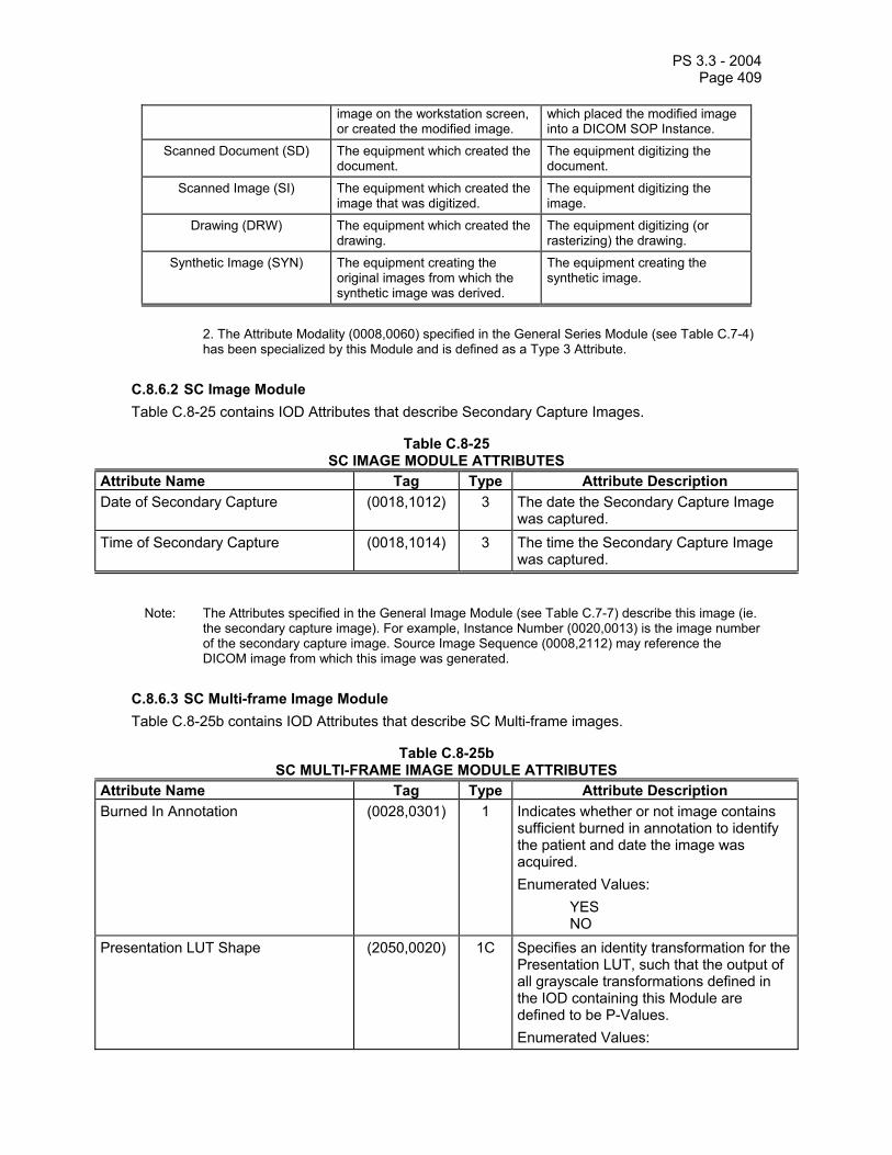
PS 3.3 - 2004 Page 409
image on the workstation screen, or created the modified image.
which placed the modified image into a DICOM SOP Instance.
Scanned Document (SD) The equipment which created the document.
The equipment digitizing the document.
Scanned Image (SI) The equipment which created the image that was digitized.
The equipment digitizing the image.
Drawing (DRW) The equipment which created the drawing.
The equipment digitizing (or rasterizing) the drawing.
Synthetic Image (SYN) The equipment creating the original images from which the synthetic image was derived.
The equipment creating the synthetic image.
2. The Attribute Modality (0008,0060) specified in the General Series Module (see Table C.7-4)
has been specialized by this Module and is defined as a Type 3 Attribute.
C.8.6.2 SC Image Module Table C.8-25 contains IOD Attributes that describe Secondary Capture Images.
Table C.8-25 SC IMAGE MODULE ATTRIBUTES
Attribute Name Tag Type Attribute Description Date of Secondary Capture (0018,1012) 3 The date the Secondary Capture Image
was captured. Time of Secondary Capture (0018,1014) 3 The time the Secondary Capture Image
was captured.
Note: The Attributes specified in the General Image Module (see Table C.7-7) describe this image (ie. the secondary capture image). For example, Instance Number (0020,0013) is the image number of the secondary capture image. Source Image Sequence (0008,2112) may reference the DICOM image from which this image was generated.
C.8.6.3 SC Multi-frame Image Module Table C.8-25b contains IOD Attributes that describe SC Multi-frame images.
Table C.8-25b SC MULTI-FRAME IMAGE MODULE ATTRIBUTES
Attribute Name Tag Type Attribute Description Burned In Annotation (0028,0301) 1 Indicates whether or not image contains
sufficient burned in annotation to identify the patient and date the image was acquired. Enumerated Values: YES NO
Presentation LUT Shape (2050,0020) 1C Specifies an identity transformation for the Presentation LUT, such that the output of all grayscale transformations defined in the IOD containing this Module are defined to be P-Values. Enumerated Values:
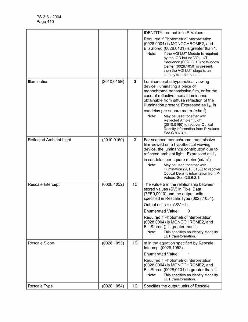
PS 3.3 - 2004 Page 410
IDENTITY - output is in P-Values. Required if Photometric Interpretation (0028,0004) is MONOCHROME2, and BitsStored (0028,0101) is greater than 1.
Note: If the VOI LUT Module is required by the IOD but no VOI LUT Sequence (0028,3010) or Window Center (0028,1050) is present, then the VOI LUT stage is an identity transformation.
Illumination (2010,015E) 3 Luminance of a hypothetical viewing device illuminating a piece of monochrome transmissive film, or for the case of reflective media, luminance obtainable from diffuse reflection of the illumination present. Expressed as L0, in candelas per square meter (cd/m2).
Note: May be used together with Reflected Ambient Light (2010,0160) to recover Optical Density information from P-Values. See C.8.6.3.1.
Reflected Ambient Light (2010,0160) 3 For scanned monochrome transmissive film viewed on a hypothetical viewing device, the luminance contribution due to reflected ambient light. Expressed as La, in candelas per square meter (cd/m2).
Note: May be used together with Illumination (2010,015E) to recover Optical Density information from P-Values. See C.8.6.3.1.
Rescale Intercept (0028,1052) 1C The value b in the relationship between stored values (SV) in Pixel Data (7FE0,0010) and the output units specified in Rescale Type (0028,1054). Output units = m*SV + b. Enumerated Value: 0 Required if Photometric Interpretation (0028,0004) is MONOCHROME2, and BitsStored () is greater than 1.
Note: This specifies an identity Modality LUT transformation.
Rescale Slope (0028,1053) 1C m in the equation specified by Rescale Intercept (0028,1052). Enumerated Value: 1 Required if Photometric Interpretation (0028,0004) is MONOCHROME2, and BitsStored (0028,0101) is greater than 1.
Note: This specifies an identity Modality LUT transformation.
Rescale Type (0028,1054) 1C Specifies the output units of Rescale

PS 3.3 - 2004 Page 411
Slope (0028,1053) and Rescale Intercept (0028,1052). Enumerated Value: US = Unspecified Required if Photometric Interpretation (0028,0004) is MONOCHROME2, and BitsStored (0028,0101) is greater than 1.
Note: This specifies an identity Modality LUT transformation.
Frame Increment Pointer (0028,0009) 1C Contains the Data Element Tag of the attribute which is used as the frame increment in Multi-frame pixel data. See C.7.6.6.1.1 for further explanation. Shall be present if Number of Frames is greater than 1, overriding (specializing) the Type 1 requirement on this attribute in the Multi-frame Module.
Nominal Scanned Pixel Spacing (0018,2010) 1C Physical distance on the media being digitized or scanned between the center of each pixel, specified by a numeric pair - adjacent row spacing (delimiter) adjacent column spacing in mm. Required if Conversion Type (0008,0064) is DF (Digitized Film). May also be present if Conversion Type (0008,0064) is SD (Scanned Document) or SI (Scanned Image). Shall be consistent with Pixel Aspect Ratio(0028,0034), if present.
Digitizing Device Transport Direction (0018,2020) 3 Enumerated Values: ROW COLUMN
Rotation of Scanned Film (0018,2030) 3 Angle of the edge of the film relative to the transport direction in degrees greater than or equal to -45 and less than or equal to +45.
C.8.6.3.1 Scanned Film, Optical Density and P-Values Illumination (2010,015E) and Reflected Ambient Light (2010,0160) may be used to recover Optical Density information from P-Values.
Monochrome media that is being digitized is often measured in Optical Density values. These values need to be converted to P-Values for storage and display. The P-Values used in an image correspond to the perception of a human observer viewing the film on a hypothetical viewing device (such as a light box), using the specified values of Illumination (2010,015E) and Reflected Ambient Light (2010,0160).
The Grayscale Standard Display Function defined in PS 3.14 is used to convert Luminance to P-Values. In the case of scanned film, the Luminance is derived from Optical Density using the specified values of Illumination (2010,015E) and Reflected Ambient Light (2010,0160). An example of this derivation, as well as typical “default” values for these parameters, is specified in PS 3.14.

PS 3.3 - 2004 Page 412
C.8.6.4 SC Multi-frame Vector Module Table C.8-25c contains IOD Attributes that may be the target of the Frame Increment Pointer (0028,0009) for SC Multi-frame images.
Table C.8-25c SC MULTI-FRAME VECTOR MODULE ATTRIBUTES
Attribute Name Tag Type Attribute Description Frame Time Vector (0018,1065) 1C An array which contains the real time
increments (in msec) between frames for a Multi-frame image. See C.7.6.5.1.2 for further explanation. Required if Frame Increment Pointer (0028,0009) points to Frame Time Vector (0018,1065).
Page Number Vector (0018,2001) 1C An array which contains, for each of the image frames, the corresponding page numbers of the original document. Required if Frame Increment Pointer (0028,0009) points to Page Number Vector (0018,2001).
Frame Label Vector (0018,2002) 1C An array which contains, for each of the image frames, a descriptive label. Required if Frame Increment Pointer (0028,0009) points to Frame Label Vector (0018,2002).
Frame Primary Angle Vector (0018,2003) 1C An array which contains, for each of the image frames, the primary angle of rotation about an undefined axis, in degrees. May be used for annotative purposes for “cine loops” of 3D reprojected images Required if Frame Increment Pointer (0028,0009) points to Frame Primary Angle Vector (0018,2003).
Frame Secondary Angle Vector (0018,2004) 1C An array which contains, for each of the image frames, the secondary angle of rotation about an undefined axis that is orthogonal to that used for Frame Primary Angle Vector (0018,2003), in degrees. May be used for annotative purposes for “cine loops” of 3D reprojected images Required if Frame Increment Pointer (0028,0009) points to Frame Secondary Angle Vector (0018,2004).
Slice Location Vector (0018,2005) 1C Relative position of exposure expressed in mm, as defined for Slice Location (0020,1041). See C.7.6.2.1.2 for further explanation. Required if Frame Increment Pointer (0028,0009) points to Slice Location

PS 3.3 - 2004 Page 413
Vector (0018,2005). Display Window Label Vector (0018,2006) 1C An array which contains, for each of the
image frames, a label or number of the display window of a graphical user interface from which the frame was captured. Required if Frame Increment Pointer (0028,0009) points to Display Window Label Vector (0018,2006).
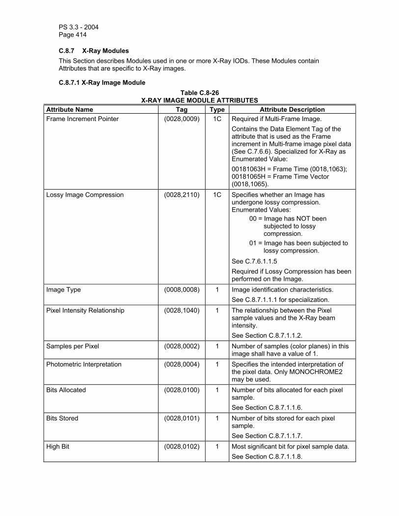
PS 3.3 - 2004 Page 414
C.8.7 X-Ray Modules This Section describes Modules used in one or more X-Ray IODs. These Modules contain Attributes that are specific to X-Ray images.
C.8.7.1 X-Ray Image Module Table C.8-26
X-RAY IMAGE MODULE ATTRIBUTES Attribute Name Tag Type Attribute Description Frame Increment Pointer (0028,0009) 1C Required if Multi-Frame Image.
Contains the Data Element Tag of the attribute that is used as the Frame increment in Multi-frame image pixel data (See C.7.6.6). Specialized for X-Ray as Enumerated Value: 00181063H = Frame Time (0018,1063); 00181065H = Frame Time Vector (0018,1065).
Lossy Image Compression (0028,2110) 1C Specifies whether an Image has undergone lossy compression. Enumerated Values:
00 = Image has NOT been subjected to lossy compression.
01 = Image has been subjected to lossy compression.
See C.7.6.1.1.5 Required if Lossy Compression has been performed on the Image.
Image Type (0008,0008) 1 Image identification characteristics. See C.8.7.1.1.1 for specialization.
Pixel Intensity Relationship (0028,1040) 1 The relationship between the Pixel sample values and the X-Ray beam intensity. See Section C.8.7.1.1.2.
Samples per Pixel (0028,0002) 1 Number of samples (color planes) in this image shall have a value of 1.
Photometric Interpretation (0028,0004) 1 Specifies the intended interpretation of the pixel data. Only MONOCHROME2 may be used.
Bits Allocated (0028,0100) 1 Number of bits allocated for each pixel sample. See Section C.8.7.1.1.6.
Bits Stored (0028,0101) 1 Number of bits stored for each pixel sample. See Section C.8.7.1.1.7.
High Bit (0028,0102) 1 Most significant bit for pixel sample data. See Section C.8.7.1.1.8.
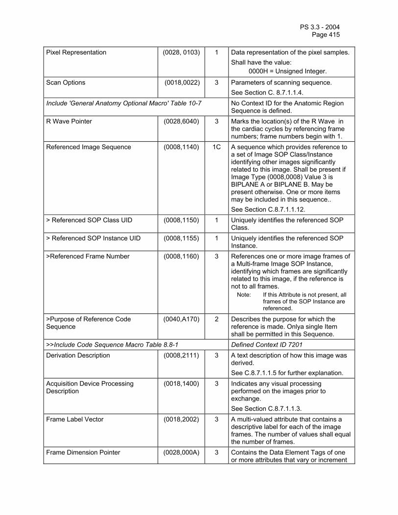
PS 3.3 - 2004 Page 415
Pixel Representation (0028, 0103) 1 Data representation of the pixel samples. Shall have the value:
0000H = Unsigned Integer.
Scan Options (0018,0022) 3 Parameters of scanning sequence. See Section C. 8.7.1.1.4.
Include 'General Anatomy Optional Macro' Table 10-7 No Context ID for the Anatomic Region Sequence is defined.
R Wave Pointer (0028,6040) 3 Marks the location(s) of the R Wave in the cardiac cycles by referencing frame numbers; frame numbers begin with 1.
Referenced Image Sequence (0008,1140) 1C A sequence which provides reference to a set of Image SOP Class/Instance identifying other images significantly related to this image. Shall be present if Image Type (0008,0008) Value 3 is BIPLANE A or BIPLANE B. May be present otherwise. One or more items may be included in this sequence.. See Section C.8.7.1.1.12.
> Referenced SOP Class UID (0008,1150) 1 Uniquely identifies the referenced SOP Class.
> Referenced SOP Instance UID (0008,1155) 1 Uniquely identifies the referenced SOP Instance.
>Referenced Frame Number (0008,1160) 3 References one or more image frames of a Multi-frame Image SOP Instance, identifying which frames are significantly related to this image, if the reference is not to all frames.
Note: If this Attribute is not present, all frames of the SOP Instance are referenced.
>Purpose of Reference Code Sequence
(0040,A170) 2 Describes the purpose for which the reference is made. Onlya single Item shall be permitted in this Sequence.
>>Include Code Sequence Macro Table 8.8-1 Defined Context ID 7201 Derivation Description (0008,2111) 3 A text description of how this image was
derived. See C.8.7.1.1.5 for further explanation.
Acquisition Device Processing Description
(0018,1400) 3 Indicates any visual processing performed on the images prior to exchange. See Section C.8.7.1.1.3.
Frame Label Vector (0018,2002) 3 A multi-valued attribute that contains a descriptive label for each of the image frames. The number of values shall equal the number of frames.
Frame Dimension Pointer (0028,000A) 3 Contains the Data Element Tags of one or more attributes that vary or increment

PS 3.3 - 2004 Page 416
for the frames of a multi-frame image. See C.8.7.1.1.12. Shall not be present if it would contain only one value and that value would be Frame Time (0018,1063) or Frame Time Vector (0018,1065).
Calibration Image (0050,0004) 3 Indicates whether a reference object (phantom) of known size is present in the image and was used for calibration. Enumerated Values:
YES NO
Device is identified using the Device module. See C.7.6.12.
C.8.7.1.1 X-Ray Image Attribute Descriptions C.8.7.1.1.1 Image Type The Image Type attribute identifies important image characteristics in a multiple valued data element. For X-Ray, Image Type is specialized as follows:
a. Value 1 shall identify the Pixel Data Characteristics in accordance with Section C.7.6.1.1.2; Enumerated Values are: ORIGINAL and DERIVED;
b. Value 2 shall identify the Patient Examination Characteristics in accordance with Section C.7.6.1.1.2; Enumerated Values are: PRIMARY and SECONDARY.
Note: X-Ray images generally use PRIMARY value for images captured from patient exposure.
c. Value 3 shall identify the image set in terms of the imaging planes. Enumerated Values are: SINGLE PLANE Image is a single plane acquisition;
BIPLANE A Image is the first plane (e.g., Frontal) of a Bi-plane acquisition;
BIPLANE B Image is the second plane (e.g., Lateral) of a Bi-plane
acquisition
d. Other Values are implementation specific (optional).

PS 3.3 - 2004 Page 417
C.8.7.1.1.2 Pixel Intensity Relationship Pixel Intensity Relationship (0028,1040) shall identify the relationship of the pixel values to the X-Ray beam intensity. Defined terms are:
LIN Approximately proportional to X-Ray beam intensity;
LOG Non-linear “ Log Function”; A Modality LUT shall be included with the image to allow it to be scaled back to its proportional value to X-Ray beam intensity;
DISP Ready to be displayed; A Modality LUT may be included with the image to allow it to be scaled back to its proportional value to X-Ray beam intensity. The Attribute Acquisition Device Processing Description may be used to provide some indication on the pre-processing performed to create the ready to be displayed image.
C.8.7.1.1.3 Acquisition Device Processing Description Acquisition Device Processing Description (0018,1400) provides some indication in human readable text of the digital processing on the images before exchange. Examples of this processing are: edge enhanced, subtracted, time filtered, gamma corrected, convolved (spatially filtered).
C.8.7.1.1.4 Scan Options The Scan Options attribute identifies any acquisition technique which was used during the acquisition of the image. Defined Terms are:
EKG EKG Event Trigger PHY Physiological Event Trigger TOMO Tomography CHASE Bolus Chasing STEP Stepping ROTA Rotation
C.8.7.1.1.5 Derivation Description If an Image is identified to be a Derived image (see C.8.9.1.1.1 Image Type), Derivation Description (0008,2111) is an optional and implementation specific text description of the way the image was derived from an original image. As applied to X-Ray images, it may be used to describe derivation operations such as edge enhancement, temporal filtering, digital subtraction, or other linear and non-linear transformations.
C.8.7.1.1.6 Bits Allocated For X-Ray Images, Bits Allocated (0028,0100) shall have the Enumerated Value of 8 or 16.
C.8.7.1.1.7 Bits Stored For X-Ray Images, Bits Stored (0028,0101) shall have the Enumerated Values of 8, 10, 12, or 16.

PS 3.3 - 2004 Page 418
C.8.7.1.1.8 High Bit For X-Ray Images, High Bit (0028,0102) shall have the Enumerated Value of one less than the value in Bit Stored.
C.8.7.1.1.9 Synchronization of Frame and Curve Times If a Curve is present and of type ECG, pressure, physiological, respiration, time activity curve, the origin of the coordinate start time (50xx, 0112) shall be the time of frame 1.
C.8.7.1.1.12 Frame Dimension Pointer
Frame Dimension Pointer (0028,000A) identifies attributes that vary or increment with each frame, and which are clinically significant for viewing or processing the image. This is intended for SOP Instances whose preferred clinical presentation is dependent on frame relationships other than simply time. Defined Terms for multiframe cine from the Cine Module (see C.7.6.5) are:
00181063H = Frame Time (0018,1063) 00181065H = Frame Time Vector (0018,1065)
Defined Terms for rotational acquisition from the XA Positioner Module (see C.8.7.5) are: 00181520H = Positioner Primary Angle Increment (0018,1520) 00181521H = Positioner Secondary Angle Increment (0018,1521)
Defined Terms for stepped acquisition from the X-Ray Table Module (see C.8.7.4) are: 00181135H = Table Vertical Increment (0018,1135) 00181137H = Table Longitudinal Increment (0018,1137) 00181136H = Table Lateral Increment (0018,1136)
Defined Terms for an arbitrary labeled increment: 00182002H = Frame Label Vector (0018,2002)
Notes: 1. Previous editions of the standard did not include the optional Frame Dimension Pointer
(0028,000A), but instead depended entirely on the mandatory Frame Increment Pointer (0028,0009), and envisaged that only time and no other dimension would relate frames. Image creators that add the Frame Dimension Pointer (0028,000A) must anticipate that many implementations will ignore or discard this attribute when displaying or storing images and continue to assume that frames are temporally related.
2. Frame Time (0018,1063) or Frame Time Vector (0018,1065) will also be present and will contain appropriate values consistent with the times of acquisition of the frames.
C.8.7.1.1.13 Referenced Image Sequence When Image Type (0008,0008) Value 3 is BIPLANE A or BIPLANE B, Referenced Image Sequence (0008,1140) shall be used to identify the corresponding SOP Instance of the Biplane acquisition. In this case, either:
- only a single item shall be present, or - multiple items may be present, each with the Purpose of Reference Code Sequence
(0040,A170) present, and only the first item having the Purpose of Reference value (121314, DCM, “Other image of biplane pair”).
C.8.7.2 X-Ray Acquisition Module
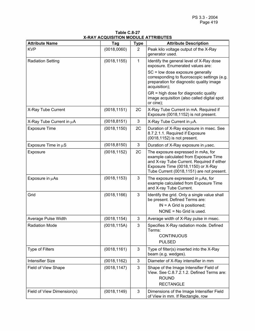
PS 3.3 - 2004 Page 419
Table C.8-27 X-RAY ACQUISITION MODULE ATTRIBUTES
Attribute Name Tag Type Attribute Description KVP (0018,0060) 2 Peak kilo voltage output of the X-Ray
generator used. Radiation Setting (0018,1155) 1 Identify the general level of X-Ray dose
exposure. Enumerated values are: SC = low dose exposure generally corresponding to fluoroscopic settings (e.g. preparation for diagnostic quality image acquisition); GR = high dose for diagnostic quality image acquisition (also called digital spot or cine);
X-Ray Tube Current (0018,1151) 2C X-Ray Tube Current in mA. Required if Exposure (0018,1152) is not present.
X-Ray Tube Current in µA (0018,8151) 3 X-Ray Tube Current in µA. Exposure Time (0018,1150) 2C Duration of X-Ray exposure in msec. See
8.7.2.1.1. Required if Exposure (0018,1152) is not present.
Exposure Time in µS (0018,8150) 3 Duration of X-Ray exposure in µsec. Exposure (0018,1152) 2C The exposure expressed in mAs, for
example calculated from Exposure Time and X-ray Tube Current. Required if either Exposure Time (0018,1150) or X-Ray Tube Current (0018,1151) are not present.
Exposure in µAs (0018,1153) 3 The exposure expressed in µAs, for example calculated from Exposure Time and X-ray Tube Current.
Grid (0018,1166) 3 Identify the grid. Only a single value shall be present. Defined Terms are:
IN = A Grid is positioned; NONE = No Grid is used.
Average Pulse Width (0018,1154) 3 Average width of X-Ray pulse in msec. Radiation Mode (0018,115A) 3 Specifies X-Ray radiation mode. Defined
Terms: CONTINUOUS PULSED
Type of Filters (0018,1161) 3 Type of filter(s) inserted into the X-Ray beam (e.g. wedges).
Intensifier Size (0018,1162) 3 Diameter of X-Ray intensifier in mm Field of View Shape (0018,1147) 3 Shape of the Image Intensifier Field of
View. See C.8.7.2.1.2. Defined Terms are: ROUND RECTANGLE
Field of View Dimension(s) (0018,1149) 3 Dimensions of the Image Intensifier Field of View in mm. If Rectangle, row

PS 3.3 - 2004 Page 420
dimension followed by column; if Round, diameter.
Imager Pixel Spacing (0018,1164) 3 Physical distance measured at the front plane of the Image Receptor housing between the center of each pixel specified by a numeric pair - row spacing value(delimiter) column spacing value in mm.
Focal Spot (0018,1190) 3 Nominal focal spot size in mm used to acquire this image.
Image Area Dose Product (0018,115E) 3 X-Ray dose, measured in dGy*cm*cm, to which the patient was exposed for the acquisition of this image plus any non-digitally recorded fluoroscopy which may have been performed to prepare for the acquisition of this image.
Note: The sum of the Image Area Dose Product of all images of a Series or a Study may not result in the actual area dose product to which the patient was exposed.
C.8.7.2.1 X-Ray Acquisition Attribute Descriptions C.8.7.2.1.1 Exposure Time Exposure time is the cumulative time the patient received X-Ray exposure during this image (Multi-frame image acquisition). Calculation is pulse width * number of frames.
C.8.7.2.1.2 Field of View The Field of View Attribute describes the shape and dimensions of the Image Intensifier Field of View (zoom mode). This could be further restricted by the Collimator. See Section C.8.7.3.
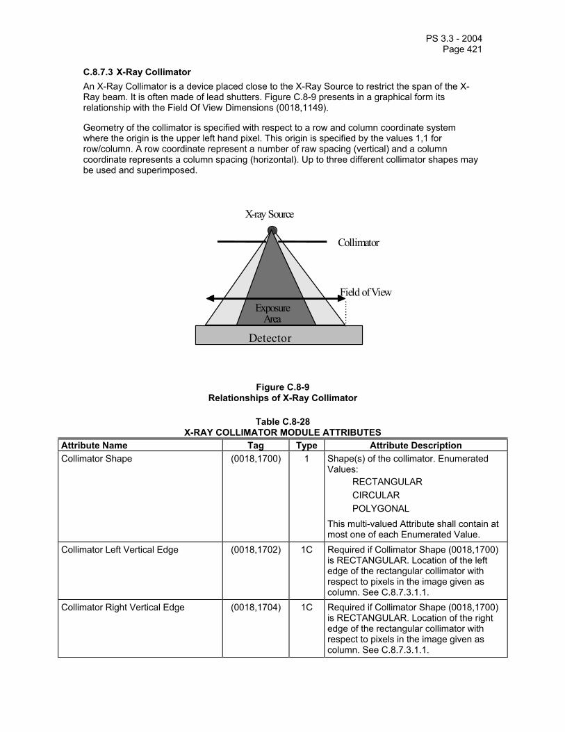
PS 3.3 - 2004 Page 421
C.8.7.3 X-Ray Collimator An X-Ray Collimator is a device placed close to the X-Ray Source to restrict the span of the X-Ray beam. It is often made of lead shutters. Figure C.8-9 presents in a graphical form its relationship with the Field Of View Dimensions (0018,1149).
Geometry of the collimator is specified with respect to a row and column coordinate system where the origin is the upper left hand pixel. This origin is specified by the values 1,1 for row/column. A row coordinate represent a number of raw spacing (vertical) and a column coordinate represents a column spacing (horizontal). Up to three different collimator shapes may be used and superimposed.
Field of View
X-ray Source
Exposure Area
Collimator
Detect o r
Figure C.8-9 Relationships of X-Ray Collimator
Table C.8-28 X-RAY COLLIMATOR MODULE ATTRIBUTES
Attribute Name Tag Type Attribute Description Collimator Shape (0018,1700) 1 Shape(s) of the collimator. Enumerated
Values: RECTANGULAR CIRCULAR POLYGONAL
This multi-valued Attribute shall contain at most one of each Enumerated Value.
Collimator Left Vertical Edge (0018,1702) 1C Required if Collimator Shape (0018,1700) is RECTANGULAR. Location of the left edge of the rectangular collimator with respect to pixels in the image given as column. See C.8.7.3.1.1.
Collimator Right Vertical Edge (0018,1704) 1C Required if Collimator Shape (0018,1700) is RECTANGULAR. Location of the right edge of the rectangular collimator with respect to pixels in the image given as column. See C.8.7.3.1.1.

PS 3.3 - 2004 Page 422
Collimator Upper Horizontal Edge (0018,1706) 1C Required if Collimator Shape (0018,1700) is RECTANGULAR. Location of the upper edge of the rectangular collimator with respect to pixels in the image given as row. See C.8.7.3.1.1.
Collimator Lower Horizontal Edge (0018,1708) 1C Required if Collimator Shape (0018,1700) is RECTANGULAR. Location of the lower edge of the rectangular collimator with respect to pixels in the image given as row. See C.8.7.3.1.1.
Center of Circular Collimator (0018,1710) 1C Required if Collimator Shape (0018,1700) is CIRCULAR. Location of the center of the circular collimator with respect to pixels in the image given as row and column. See C.8.7.3.1.1.
Radius of Circular Collimator (0018,1712) 1C Required if Collimator Shape (0018,1700) is CIRCULAR. Radius of the circular collimator with respect to pixels in the image given as a number of pixels along the row direction. See C.8.7.3.1.1.
Vertices of the Polygonal Collimator (0018,1720) 1C Required if Collimator Shape (0018,1700) is POLYGONAL. Multiple Values where the first set of two values are:
row of the origin vertex; column of the origin vertex.
Two or more pairs of values follow and are the row and column coordinates of the other vertices of the polygon collimator. Polygon collimators are implicitly closed from the last vertex to the origin vertex and all edges shall be non-intersecting except at the vertices.
C.8.7.3.1 X-Ray Collimator Attribute Descriptions C.8.7.3.1.1 Collimator Vertical and Horizontal Edges These attributes specify the pixel row or column where the X-ray beam is fully obscured by a rectangular collimator:
- if the left edge of the collimator is not visible, Collimator Left Vertical Edge (0018,1702) shall have a value of 0;
- if the right edge of the collimator is not visible, Collimator Right Vertical Edge (0018,1704) value shall be 1 greater than the value of the Columns (0028,0011) attribute;
- if the top edge of the collimator is not visible, Collimator Upper Horizontal Edge (0018,1706) shall have a value of 0;
- if the bottom edge of the collimator is not visible, Collimator Lower Horizontal Edge (0018,1708) value shall be 1 greater than the value of the Rows (0028,0010) attribute.
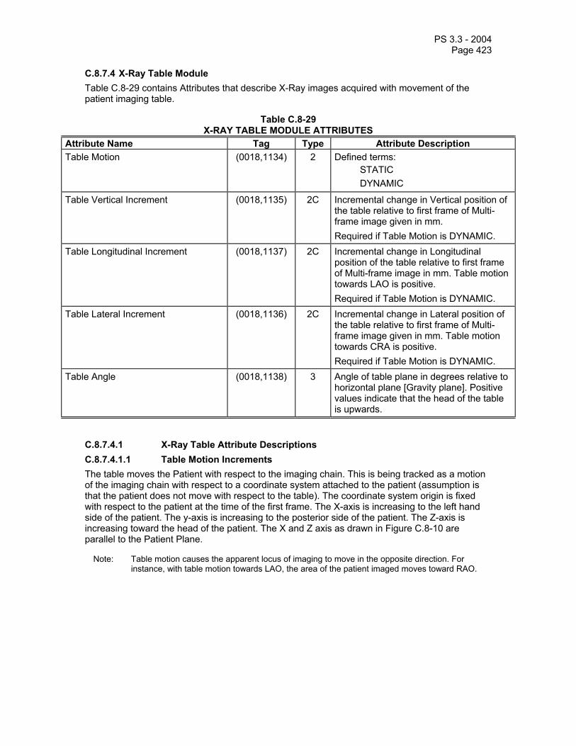
PS 3.3 - 2004 Page 423
C.8.7.4 X-Ray Table Module Table C.8-29 contains Attributes that describe X-Ray images acquired with movement of the patient imaging table.
Table C.8-29 X-RAY TABLE MODULE ATTRIBUTES
Attribute Name Tag Type Attribute Description Table Motion (0018,1134) 2 Defined terms:
STATIC DYNAMIC
Table Vertical Increment (0018,1135) 2C Incremental change in Vertical position of the table relative to first frame of Multi-frame image given in mm. Required if Table Motion is DYNAMIC.
Table Longitudinal Increment (0018,1137) 2C Incremental change in Longitudinal position of the table relative to first frame of Multi-frame image in mm. Table motion towards LAO is positive. Required if Table Motion is DYNAMIC.
Table Lateral Increment (0018,1136) 2C Incremental change in Lateral position of the table relative to first frame of Multi-frame image given in mm. Table motion towards CRA is positive. Required if Table Motion is DYNAMIC.
Table Angle (0018,1138) 3 Angle of table plane in degrees relative to horizontal plane [Gravity plane]. Positive values indicate that the head of the table is upwards.
C.8.7.4.1 X-Ray Table Attribute Descriptions C.8.7.4.1.1 Table Motion Increments The table moves the Patient with respect to the imaging chain. This is being tracked as a motion of the imaging chain with respect to a coordinate system attached to the patient (assumption is that the patient does not move with respect to the table). The coordinate system origin is fixed with respect to the patient at the time of the first frame. The X-axis is increasing to the left hand side of the patient. The y-axis is increasing to the posterior side of the patient. The Z-axis is increasing toward the head of the patient. The X and Z axis as drawn in Figure C.8-10 are parallel to the Patient Plane.
Note: Table motion causes the apparent locus of imaging to move in the opposite direction. For instance, with table motion towards LAO, the area of the patient imaged moves toward RAO.

PS 3.3 - 2004 Page 424
+Y
+X
+Z
PatientPlane
Figure C.8-10 Table Motion Vector Coordinates
C.8.7.5 XA Positioner Module Table C.8-30 contains IOD Attributes that describe a c-arm positioner typically used in acquiring X-Ray Angiographic Images. The coordinate system used to track the positioner is defined in reference to the patient. The definition of coordinates with respect to the equipment is not supported. Furthermore, this module does not describe the movement of the Patient.
Note: The scope of the XA IOD is to address images produced on acquisition equipment equipped with an X-Ray source and an image Receptor positioned by what is general called a c-arm For clinical areas other than Angiography which are using a c-arm to position the X-Ray source and image receptor (e.g. Interventional Procedures and Myelography and Biopsy/Localization), the X-Ray Angiography Image Object should be also used. Although the object is optimized for c-arm systems, it may also be used by other systems which support a similar coordinate system, such as some RF systems.
Table C.8-30 XA POSITIONER MODULE ATTRIBUTES
Attribute Name Tag Type Attribute Description Distance Source to Patient (0018,1111) 3 Distance in mm from source to isocenter
(center of field of view). Note: This value is traditionally referred to
as Source Object Distance (SOD).
Distance Source to Detector (0018,1110) 3 Distance in mm from source to detector center.
Note: This value is traditionally referred to as Source Image Receptor Distance (SID).
Estimated Radiographic Magnification Factor
(0018,1114) 3 Ratio of Source Image Receptor Distance (SID) over Source Object Distance (SOD).
Positioner Motion (0018,1500) 2C Used to describe the activity of the imaging devices. Defined terms: DYNAMIC, STATIC. Required if Multi-frame data. See C.8.7.5.1.1.
Positioner Primary Angle (0018,1510) 2 Position of the X-Ray Image Intensifier about the patient from the RAO to LAO

PS 3.3 - 2004 Page 425
direction where movement from RAO to vertical is positive. See C.8.7.5.1.2.
Positioner Secondary Angle (0018,1511) 2 Position of the X-Ray Image Intensifier about the patient from the CAU to CRA direction where movement from CAU to vertical is positive. See C.8.7.5.1.2
Positioner Primary Angle Increment (0018,1520) 2C Incremental change in primary positioner angle for each frame. See C.8.7.5.1.3. Required if Positioner Motion is DYNAMIC.
Positioner Secondary Angle Increment (0018,1521) 2C Incremental change in secondary positioner angle for each frame. See C.8.7.5.1.3. Required if Positioner Motion is DYNAMIC.
Detector Primary Angle (0018,1530) 3 Angle of the X-Ray beam in the row direction in degrees relative to the normal to the detector plane. Positive values indicate that the X-Ray beam is tilted towards higher numbered columns. Negative values indicate that the X-Ray beam is tilted towards lower numbered columns. See C.8.7.5.1.4.
Detector Secondary Angle (0018,1531) 3 Angle of the X-Ray beam in the column direction in degrees relative to the normal to the detector plane. Positive values indicate that the X-Ray beam is tilted towards lower numbered rows. Negative values indicate that the X-Ray beam is tilted towards higher numbered rows. See C.8.7.5.1.4.
C.8.7.5.1 XA Positioner Attribute Descriptions C.8.7.5.1.1 Positioner Motion Positioner Motion attribute is STATIC if the imaging table moves during a multi-frame acquisition, but the X-Ray positioner do not move.
Note: If the positioner undergoes translation (non-rotational movement) during the acquisition, then that motion shall be described by an opposite table motion (See Section C.8.7.4).
C.8.7.5.1.2 Positioner Primary and Secondary Angles The definitions of Positioner Angles shall be with respect to the patient as illustrated in Figures C.8-11 and C.8-12 Zero degree is referenced to the origin perpendicular to the patient's chest. The Positioner Primary Angle definition is like longitude (in the equatorial plan); the Positioner Secondary Angle definition is like latitude (in the sagittal plane). The Positioner Angle attributes

PS 3.3 - 2004 Page 426
apply to the first frame of a multi-frame image. The valid range of Primary Positioner Angle is -180 to +180 degrees and the Secondary Positioner Angle range is -90 to + 90 degrees.
The Patient Plane is defined by the isocenter of the imaging device and slices through the patient such that it is perpendicular to the sagittal plane of the body. The Primary Axis of rotation is defined at the intersection of the Patient Plane and of the Sagittal Plane. The Positioner Primary Angle is defined in the transaxial plane at the isocenter with zero degrees in the direction perpendicular to the patient's chest and + 90 degrees at the Patient left hand side (LAO) and -90 at the Patient right hand side (RAO). The valid range of Primary Positioner Angle is -180 to +180 degrees.
The Secondary Axis is in the Patient Plane and is perpendicular to the Primary Axis at the isocenter. The Positioner Secondary Angle is defined in the Sagittal Plane at the isocenter with zero degrees in the direction perpendicular to the patient's chest. +90 degrees corresponds to the cranial direction. The Secondary Positioner Angle range is -90 to + 90 degrees.
At a 0 angle for both the Primary Angle (0018,1510) and Secondary Angle (0018,1511), the patient faces the Image Intensifier.
The Positioner Primary Angle (0018,1510) and Secondary Angle (0018,1511) apply to the first frame of a multi-frame image.
0°
RAO = -90°
LAO = +90°
+/- 180°
PatientPlane
Axis ofRotation
Figure C.8-11 Positioner Primary Angle

PS 3.3 - 2004 Page 427
CAU = -90°
CRA = +90°
0°
PatientPlane
Axis ofRotation
Figure C.8-12 Positioner Secondary Angle
C.8.7.5.1.3 Positioner Angle Increments If the positioner angles change during acquisition of a multi-frame image, the Positioner Angle Increment attributes describe the angular change per frame.
If the change in positioner angle is nominally constant for each frame, these fields may contain a single value of the average angular change per frame. Alternatively, the fields may contain a vector of offsets from the (initial) Positioner Angle attributes, with one value for each frame in the multi-frame image. The number of values in the Positioner Angle Increment attributes must be one, or must be equal to the Number of Frames attribute (0028,0008) in the Multi-Frame Module (see Section C.7.6.6).
Note: It is permissible to generate a vector of the absolute positioner angles in the Positioner Angle Increment attributes, and set the Positioner Primary and Secondary Angle attributes to value 0.
C.8.7.5.1.4 Detector Primary and Secondary Angles Detector Angles are defined in a fashion similar to the positioner angles, except that the angle of the central x-ray beam vector is relative to the detector plane rather than the patient plane. The central x-ray beam vector is defined as the vector from the x-ray source through the isocenter to the detector plane. Zero degree is referenced to the normal to the detector plane pointing away from the x-ray source. The Detector Angle attributes apply to the first frame of a multi-frame image. The valid range of the Detector Angles is -90 to + 90 degrees.
The Primary Axis of rotation is defined along the line in the column direction of the detector plane which intersects the central x-ray beam vector. The Detector Primary Angle is defined in the plane perpendicular to the Primary Axis of rotation at the point where the central x-ray beam vector intersects the detector plane, with zero degrees in the direction normal to the detector plane and -90 degrees at the left hand side of the image (i.e., toward column 1) and +90 at the right hand side of the image (i.e., toward the highest numbered column). The valid range of Primary Detector Angle is -90 to +90 degrees.

PS 3.3 - 2004 Page 428
The Secondary Axis is in the detector plane and is perpendicular to the Primary Axis at the intersection of the beam vector with the detector plane (i.e., it is along the row direction). The Detector Secondary Angle is defined in the plane perpendicular to the Secondary Axis at the point where the central x-ray beam vector intersects the detector plane, with zero degrees in the direction normal to the detector plane. +90 degrees corresponds to the direction toward the top of the image. The Secondary Detector Angle range is -90 to + 90 degrees.
C.8.7.6 XRF Positioner Module Table C.8-31
XRF POSITIONER MODULE ATTRIBUTES Attribute Name Tag Type Attribute Description Distance Source to Detector (0018,1110) 3 Distance in mm from source to detector
center. Note: This value is traditionally referred to
as Source Image Receptor Distance (SID).
Distance Source to Patient (0018,1111) 3 Distance in mm from source to isocenter (center of field of view).
Note: This value is traditionally referred to as Source Object Distance (SOD).
Estimated Radiographic Magnification Factor
(0018,1114) 3 Ratio of SID (Source Image Receptor Distance) over SOD (Source Object Distance).
Column Angulation (0018,1450) 3 Angle of the X-Ray beam in degree relative to an orthogonal axis to the detector plane. Positive values indicate that the tilt is towards the head of the table.
Note: The detector plane is assumed to be parallel to the table plane.
C.8.7.7 X-Ray Tomography Acquisition Module This Module describes the attributes of a Tomography acquisition (translation of X-Ray source during the acquisition of a single frame image).
Table C.8-32 X-RAY TOMOGRAPHY ACQUISITION MODULE ATTRIBUTES
Attribute Name Tag Type Attribute Description Tomo Layer Height (0018,1460) 1 Distance in mm between the table surface
and the sharp image plane. Tomo Angle (0018,1470) 3 Angle span in degrees of rotation of X-Ray
Source during X-Ray acquisition. Tomo Time (0018,1480) 3 Time in seconds the source has taken to
rotate the Tomo Angle during X-Ray acquisition.
Tomo Type (0018,1490) 3 Type of tomography. Defined Terms: LINEAR SPIRAL POLYCYCLOIDAL CIRCULAR

PS 3.3 - 2004 Page 429
Tomo Class (0018,1491) 3 Form of tomography: Defined Terms: MOTION TOMOSYNTHESIS
Number of Tomosynthesis Source Images
(0018,1495) 3 The number of source images used to construct this tomosynthetic image. Only meaningful if Tomo Class (0018,1491) is TOMOSYNTHESIS. These may be listed in Source Image Sequence (0008,2112) of the General Image Module.
C.8.7.8 X-Ray Acquisition Dose Module This Module describes the attributes related to dose delivery from an X-Ray source during the acquisition of an X-Ray image.
Table C.8-33 X-RAY ACQUISITION DOSE MODULE ATTRIBUTES
Attribute Name Tag Type Attribute Description KVP (0018,0060) 3 Peak kilo voltage output of the X-Ray
generator used. X-Ray Tube Current (0018,1151) 3 X-Ray Tube Current in mA.
X-Ray Tube Current in µA (0018,8151) 3 X-Ray Tube Current in µA. Exposure Time (0018,1150) 3 Duration of X-Ray exposure in msec.
Exposure Time in µS (0018,8150) 3 Duration of X-Ray exposure in µsec. Exposure (0018,1152) 3 The exposure expressed in mAs, for
example calculated from Exposure Time and X-ray Tube Current.
Exposure in µAs (0018,1153) 3 The exposure expressed in µAs, for example calculated from Exposure Time and X-ray Tube Current.
Distance Source to Detector (0018,1110) 3 Distance in mm from source to detector center.
Note: This value is traditionally referred to as Source Image Receptor Distance (SID).
Distance Source to Patient (0018,1111) 3 Distance in mm from source to the table, support or bucky side that is closest to the Imaging Subject, as measured along the central ray of the X-Ray beam.
Note: 1. This definition is less useful in terms of estimating geometric magnification than a measurement to a defined point within the Imaging Subject, but accounts for what is realistically measurable in an automated fashion in a clinical setting.
2. This measurement does not take into account any air gap between the Imaging Subject and

PS 3.3 - 2004 Page 430
the “front” of the table or bucky. 3. If the detector is not mounted in
a table or bucky, then the actual position relative to the patient is implementation or operator defined.
4. This value is traditionally referred to as Source Object Distance (SOD).
Image Area Dose Product (0018,115E) 3 X-Ray dose, measured in dGy*cm*cm, to which the patient was exposed for the acquisition of this image plus any non-digitally recorded fluoroscopy which may have been performed to prepare for the acquisition of this image.
Notes: 1. The sum of the Image Area Dose Product of all images of a Series or a Study may not result in the actual area dose product to which the patient was exposed.
2. This may be an estimated value based on assumptions about the patient’s body size and habitus.
Body Part Thickness (0018,11A0) 3 The average thickness in mm of the body part examined when compressed, if compression has been applied during exposure.
Relative X-Ray Exposure (0018,1405) 3 Indication of the applied dose, in manufacturer specific units.
Notes: 1. This value is intended to provide a single location where manufacturer specific information can be found for annotation on a display or film, that has meaning to a knowledgeable observer.
2. This may be a calculated or measured value. Examples are the detector entrance dose (KB), the CR sensitivity value (S), or the logarithmic median (lgM).
Entrance Dose (0040,0302) 3 Average entrance dose value measured in dGy at the surface of the patient during the acquisition of this image.
Note: This may be an estimated value based on assumptions about the patient’s body size and habitus.
Entrance Dose in mGy (0040,8302) 3 Average entrance dose value measured in mGy at the surface of the patient during the acquisition of this image.
Note: This may be an estimated value based on assumptions about the patient’s body size and habitus.
Exposed Area (0040,0303) 3 Typical dimension of the exposed area at the detector plane. If Rectangular: row

PS 3.3 - 2004 Page 431
dimension followed by column; if Round: diameter. Measured in cm.
Notes: 1. The exposed area should be consistent with values specified in the X-Ray Collimator Module, if present.
2. This may be an estimated value based on assumptions about the patient’s body size and habitus.
Distance Source to Entrance (0040,0306) 3 Distance in mm from the source to the surface of the patient closest to the source during the acquisition of this image.
Note: This may be an estimated value based on assumptions about the patient’s body size and habitus.
Comments on Radiation Dose (0040,0310) 3 User-defined comments on any special conditions related to radiation dose encountered during the acquisition of this image.
X-Ray Output (0040,0312) 3 The X-Ray output at the patient entrance surface and kVp used to acquire the image, measured in mGy/mAs.
Note: This value may be a calibrated value rather than measured during the exposure.
Half Value Layer (0040,0314) 3 The thickness of Aluminum in mm required to reduce the X-Ray Output (0040,0312) by a factor of two.
Note: This value may be a calibrated value rather than measured during the exposure.
Organ Dose (0040,0316) 3 Average organ dose value measured in dGy during the acquisition of this image.
Note: This may be an estimated value.
Organ Exposed (0040,0318) 3 Organ to which Organ Dose (0040,0316) applies. Defined Terms: BREAST GONADS BONE MARROW FETUS LENS
Note: The anatomic regions described by these terms are those that are particularly radiosensitive and for which it is conventional to obtain organ specific dose parameters.
Anode Target Material (0018,1191) 3 The primary material in the anode of the X-Ray source. Defined Terms: TUNGSTEN MOLYBDENUM

PS 3.3 - 2004 Page 432
RHODIUM Filter Material (0018,7050) 3 The X-Ray absorbing material used in the
filter. May be multi-valued. Defined Terms: MOLYBDENUM ALUMINUM COPPER RHODIUM NIOBIUM EUROPIUM LEAD
Filter Thickness Minimum (0018,7052) 3 The minimum thickness in mm of the X-Ray absorbing material used in the filters. May be multi-valued, with values corresponding to the respective values in Filter Material (0018,7050).
Filter Thickness Maximum (0018,7054) 3 The maximum thickness in mm of the X-Ray absorbing material used in the filters. May be multi-valued, with values corresponding to the respective values in Filter Material (0018,7050).
Rectification Type (0018,1156) 3 Type of rectification used in the X-Ray generator. Defined Terms: SINGLE PHASE THREE PHASE CONST POTENTIAL
C.8.7.9 X-Ray Generation Module This Module describes the attributes related to generation of X-rays during the acquisition of an X-Ray image.
Table C.8-34 X-RAY GENERATION MODULE ATTRIBUTES
Attribute Name Tag Type Attribute Description KVP (0018,0060) 3 Peak kilo voltage output of the X-Ray
generator used. X-Ray Tube Current (0018,1151) 3 X-Ray Tube Current in mA.
X-Ray Tube Current in µA (0018,8151) 3 X-Ray Tube Current in µA. Exposure Time (0018,1150) 3 Duration of X-Ray exposure in msec.
Exposure Time in µS (0018,8150) 3 Duration of X-Ray exposure in µsec. Exposure (0018,1152) 3 The exposure expressed in mAs, for
example calculated from Exposure Time and X-ray Tube Current.
Exposure in µAs (0018,1153) 3 The exposure expressed in µAs, for example calculated from Exposure Time and X-ray Tube Current.

PS 3.3 - 2004 Page 433
Exposure Control Mode (0018,7060) 3 Type of exposure control. Defined Terms: MANUAL AUTOMATIC
Exposure Control Mode Description (0018,7062) 3 Text description of the mechanism of exposure control. May describe the number and type of exposure sensors or position of the sensitive area of the imaging detector.
Exposure Status (0018,7064) 3 Whether the exposure was normally completed or not. Defined Terms: NORMAL ABORTED
Phototimer Setting (0018,7065) 3 Nominal percentage phototimer setting, where a more positive value indicates greater exposure and a more negative value indicates less exposure.
Focal Spot (0018,1190) 3 Nominal focal spot size in mm used to acquire this image.
Anode Target Material (0018,1191) 3 The primary material in the anode of the X-Ray source. Defined Terms: TUNGSTEN MOLYBDENUM RHODIUM
Rectification Type (0018,1156) 3 Type of rectification used in the X-Ray generator. Defined Terms: SINGLE PHASE THREE PHASE CONST POTENTIAL
C.8.7.10 X-Ray Filtration Module This Module describes the attributes related to the filtration of X-rays during the acquisition of an X-Ray image.
Table C.8-35 X-RAY FILTRATION MODULE ATTRIBUTES
Attribute Name Tag Type Attribute Description Filter Type (0018,1160) 3 Type of filter(s) inserted into the X-Ray
beam (e.g. wedges). Defined Terms: STRIP WEDGE BUTTERFLY MULTIPLE

PS 3.3 - 2004 Page 434
NONE Filter Material (0018,7050) 3 The X-Ray absorbing material used in the
filter. May be multi-valued. Defined Terms: MOLYBDENUM ALUMINUM COPPER RHODIUM NIOBIUM EUROPIUM LEAD
Filter Thickness Minimum (0018,7052) 3 The minimum thickness in mm of the X-Ray absorbing material used in the filters. May be multi-valued, with values corresponding to the respective values in Filter Material (0018,7050).
Filter Thickness Maximum (0018,7054) 3 The maximum thickness in mm of the X-Ray absorbing material used in the filters. May be multi-valued, with values corresponding to the respective values in Filter Material (0018,7050).
C.8.7.11 X-Ray Grid Module This Module describes the attributes related to the use of a grid to reduce scatter of X-rays during the acquisition of an X-Ray image.
Table C.8-36 X-RAY GRID MODULE ATTRIBUTES
Attribute Name Tag Type Attribute Description Grid (0018,1166) 3 Identifies the grid. May be multi-valued.
Defined Terms are: FIXED FOCUSED RECIPROCATING PARALLEL CROSSED NONE
Grid Absorbing Material (0018,7040) 3 The X-Ray absorbing material used in the grid.
Grid Spacing Material (0018,7041) 3 The spacing material used in the grid. Grid Thickness (0018,7042) 3 The thickness in mm of the X-Ray
absorbing material used in the grid. Grid Pitch (0018,7044) 3 The pitch in mm of the X-Ray absorbing
material used in the grid. Grid Aspect Ratio (0018,7046) 3 Ratio of the vertical spacing and horizontal
spacing of the X-Ray absorbing material used in the grid. Specified by a pair of integer values where the first value is the vertical size, and the second value is the

PS 3.3 - 2004 Page 435
horizontal size. Grid Period (0018,7048) 3 Period in mSec of reciprocation cycle.
Only meaningful if Grid (0018,1166) is RECIPROCATING.
Grid Focal Distance (0018,704C) 3 Focal distance in mm of a FOCUSED grid.

PS 3.3 - 2004 Page 436
C.8.8 Radiotherapy Modules This Section describes Radiotherapy-specific modules.
Modules defined here make reference to “IEC” coordinate systems and standards. These standards are defined in IEC Standard 61217, “Radiotherapy Equipment - Coordinates, Movements and Scales” (Reference CEI/IEC 61217: 1996).
Note: IEC document 62C/269/CDV “Amendment to IEC 61217: Radiotherapy Equipment – Coordinates, movements and scales” also defines a patient-based coordinate system, and specifies the relationship between the DICOM Patient Coordinate System (see Section C.7.6.2.1.1) and the IEC PATIENT Coordinate System. Rotating the IEC PATIENT Coordinate System described in IEC 62C/269/CDV (1999) by 90 degrees counter-clockwise (in the negative direction) about the x-axis yields the DICOM Patient Coordinate System, i.e. (XDICOM, YDICOM, ZDICOM) = (XIEC, -ZIEC, YIEC). Refer to the latest IEC documentation for the current definition of the IEC PATIENT Coordinate System.
Many of the dosimetry concepts referred to in this document can be found in ICRU Report 50, Prescribing, Recording, and Reporting Photon Beam Therapy, International Commission on Radiation Units and Measurements, 1993.
C.8.8.1 RT Series Module There exist significant differences in the manner in which RT objects as compared to diagnostic objects. An RT object can be one of several types, and a series of a given object type may be created over a temporal span of several weeks. The RT Series Module has been created to satisfy the requirements of the standard DICOM Query/Retrieve model while including only those attributes relevant to the identification and selection of radiotherapy objects.
Table C.8-37 - RT SERIES MODULE ATTRIBUTES Attribute Name Tag Type Attribute Description Modality (0008,0060) 1 Type of equipment that originally acquired
the data. Enumerated Values: RTIMAGE = RT Image RTDOSE = RT Dose RTSTRUCT = RT Structure Set RTPLAN = RT Plan RTRECORD = RT Treatment Record See C.8.8.1.1.
Series Instance UID (0020,000E) 1 Unique identifier of the series. Series Number (0020,0011) 2 A number that identifies this series. Series Description (0008,103E) 3 User provided description of the series. Referenced Performed Procedure Step Sequence
(0008,1111) 3 Uniquely identifies the Performed Procedure Step SOP Instance to which the Series is related (e.g. a Modality or General-Purpose Performed Procedure Step SOP Instance or Study Component SOP Instance). One or more items may be included in this sequence.
>Referenced SOP Class UID (0008,1150) 1C Uniquely identifies the referenced SOP Class. Required if Referenced Performed Procedure Step Sequence (0008,1111) is sent.

PS 3.3 - 2004 Page 437
>Referenced SOP Instance UID (0008,1155) 1C Uniquely identifies the referenced SOP Instance. Required if Referenced Performed Procedure Step Sequence (0008,1111) is sent.
Request Attributes Sequence (0040,0275) 3 Sequence that contains attributes from the Imaging Service Request. The sequence may have one or more Items.
>Requested Procedure ID (0040,1001) 1C Identifier which identifies the Requested Procedure in the Imaging Service Request. Required if Sequence Item is present.
>Scheduled Procedure Step ID (0040,0009) 1C Identifier which identifies the Scheduled Procedure Step. Required if Sequence Item is present.
>Scheduled Procedure Step Description
(0040,0007) 3 Institution-generated description or classification of the Scheduled Procedure Step to be performed.
>Scheduled Protocol Code Sequence (0040,0008) 3 Sequence describing the Scheduled Protocol following a specific coding scheme. This sequence contains one or more Items.
>>Include ‘Code Sequence Macro’ Table 8.8-1 No Baseline Context ID is defined. >>Protocol Context Sequence (0040,0440) 3 Sequence that specifies the context for the
Scheduled Protocol Code Sequence Item. One or more items may be included in this sequence.
>>>Include ‘Content Item Macro’ Table 10-2 No Baseline Template is defined. >>> Content Item Modifier Sequence (0040,0441) 3 Sequence that specifies modifiers for a
Protocol Context Content Item. One or more items may be included in this sequence. See Section C.4.10.1.
>>>>Include ‘Content Item Macro’ Table 10-2 No Baseline Template is defined. Performed Procedure Step ID (0040,0253) 3 User or equipment generated identifier of
that part of a Procedure that has been carried out within this step.
Performed Procedure Step Start Date (0040,0244) 3 Date on which the Performed Procedure Step started.
Performed Procedure Step Start Time (0040,0245) 3 Time on which the Performed Procedure Step started.
Performed Procedure Step Description (0040,0254) 3 Institution-generated description or classification of the Procedure Step that was performed.
Performed Protocol Code Sequence (0040,0260) 3 Sequence describing the Protocol performed for this Procedure Step. One or more Items may be included in this Sequence.
>Include ‘Code Sequence Macro’ Table 8.8-1 No Baseline Context ID is defined. >Protocol Context Sequence (0040,0440) 3 Sequence that specifies the context for the

PS 3.3 - 2004 Page 438
Performed Protocol Code Sequence Item. One or more items may be included in this sequence.
>>Include ‘Content Item Macro’ Table 10-2 No Baseline Template is defined. >> Content Item Modifier Sequence (0040,0441) 3 Sequence that specifies modifiers for a
Protocol Context Content Item. One or more items may be included in this sequence. See Section C.4.10.1.
>>>Include ‘Content Item Macro’ Table 10-2 No Baseline Template is defined.
C.8.8.1.1 Modality The Enumerated Value for Modality (0008,0060) shall determined by the IOD:
RTIMAGE if RT Image IOD,
RTDOSE if RT Dose IOD,
RTSTRUCT if RT Structure Set IOD,
RTPLAN if RT Plan IOD,
RTRECORD if RT Beams Treatment Record IOD, RT Brachy Treatment Record IOD, or RT Treatment Summary Record IOD.
Note: DICOM specifies that a given series shall contain objects of only one Modality, and shall be created by a single device (described in the General Equipment Module). However, in general there may be many series defined for a given modality/device pair. Note that a radiotherapy series is generally created over an extended time interval (unlike in radiology, where all images in an image series are generally created together).
C.8.8.2 RT Image Module Table C.8-38 contains attributes that describe RT-specific characteristics of a projection image. The image described by these attributes must be a radiotherapy image acquired or calculated using a conical imaging geometry.
Table C.8-38—RT IMAGE MODULE ATTRIBUTES Attribute Name Tag Type Attribute Description Samples per Pixel (0028,0002) 1 Number of samples (planes) in this image.
See C.8.8.2.6.1 for specialization. Photometric Interpretation (0028,0004) 1 Specifies the intended interpretation of the
pixel data. See C.8.8.2.6.2 for specialization.
Bits Allocated (0028,0100) 1 Number of bits allocated for each pixel sample. Each sample shall have the same number of bits allocated. See C.8.8.2.6.3 for specialization.
Bits Stored (0028,0101) 1 Number of bits stored for each pixel sample. Each sample shall have the same number of bits stored. See C.8.8.2.6.4 for specialization.
High Bit (0028,0102) 1 Most significant bit for each pixel sample.
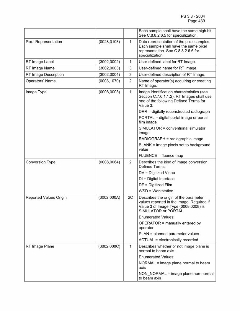
PS 3.3 - 2004 Page 439
Each sample shall have the same high bit. See C.8.8.2.6.5 for specialization.
Pixel Representation (0028,0103) 1 Data representation of the pixel samples. Each sample shall have the same pixel representation. See C.8.8.2.6.6 for specialization.
RT Image Label (3002,0002) 1 User-defined label for RT Image. RT Image Name (3002,0003) 3 User-defined name for RT Image. RT Image Description (3002,0004) 3 User-defined description of RT Image. Operators’ Name (0008,1070) 2 Name of operator(s) acquiring or creating
RT Image. Image Type (0008,0008) 1 Image identification characteristics (see
Section C.7.6.1.1.2). RT Images shall use one of the following Defined Terms for Value 3: DRR = digitally reconstructed radiograph PORTAL = digital portal image or portal film image SIMULATOR = conventional simulator image RADIOGRAPH = radiographic image BLANK = image pixels set to background value FLUENCE = fluence map
Conversion Type (0008,0064) 2 Describes the kind of image conversion. Defined Terms: DV = Digitized Video DI = Digital Interface DF = Digitized Film WSD = Workstation
Reported Values Origin (3002,000A) 2C Describes the origin of the parameter values reported in the image. Required if Value 3 of Image Type (0008,0008) is SIMULATOR or PORTAL. Enumerated Values: OPERATOR = manually entered by operator PLAN = planned parameter values ACTUAL = electronically recorded
RT Image Plane (3002,000C) 1 Describes whether or not image plane is normal to beam axis. Enumerated Values: NORMAL = image plane normal to beam axis NON_NORMAL = image plane non-normal to beam axis

PS 3.3 - 2004 Page 440
X-Ray Image Receptor Translation (3002,000D) 3 Position in (x,y,z) coordinates of origin of IEC X-RAY IMAGE RECEPTOR System in the IEC GANTRY coordinate system (mm). See Note 2.
X-Ray Image Receptor Angle (3002,000E) 2 X-Ray Image Receptor Angle i.e. orientation of IEC X-RAY IMAGE RECEPTOR coordinate system with respect to IEC GANTRY coordinate system (degrees). See C.8.8.2.2.
RT Image Orientation (3002,0010) 2C The direction cosines of the first row and the first column with respect to the IEC X-RAY IMAGE RECEPTOR coordinate system. Required if RT Image Plane (3002,000C) is NON_NORMAL.
Image Plane Pixel Spacing (3002,0011) 2 Physical distance (in mm) between the center of each image pixel, specified by a numeric pair - adjacent row spacing (delimiter) adjacent column spacing. See C.8.8.2.3.
RT Image Position (3002,0012) 2 The x and y coordinates (in mm) of the upper left hand corner of the image, in the IEC X-RAY IMAGE RECEPTOR coordinate system. This is the center of the first pixel transmitted.
Radiation Machine Name (3002,0020) 2 User-defined name identifying radiation machine used in acquiring or computing image (i.e. name of conventional simulator, electron accelerator, X-ray device, or machine modeled when calculating DRR).
Primary Dosimeter Unit (300A,00B3) 2 Measurement unit of machine dosimeter. Enumerated Values: MU = Monitor Unit MINUTE = minute
Radiation Machine SAD (3002,0022) 2 Radiation source to Gantry rotation axis distance of radiation machine used in acquiring or computing image (mm).
Radiation Machine SSD (3002,0024) 3 Source to patient surface distance (in mm) of radiation machine used in acquiring or computing image.
RT Image SID (3002,0026) 2 Distance from radiation machine source to image plane (in mm) along radiation beam axis. See C.8.8.2.3.
Source to Reference Object Distance (3002,0028) 3 Source to reference object distance (in mm), as used for magnification calculation of RADIOGRAPH and SIMULATOR images.
Referenced RT Plan Sequence (300C,0002) 3 Introduces sequence of one Class/Instance pair describing RT Plan associated with image. Only a single item shall be permitted in this sequence.

PS 3.3 - 2004 Page 441
>Referenced SOP Class UID (0008,1150) 1C Uniquely identifies the referenced SOP Class. Required if Referenced RT Plan Sequence (300C,0002) is sent.
>Referenced SOP Instance UID (0008,1155) 1C Uniquely identifies the referenced SOP Instance. Required if Referenced RT Plan Sequence (300C,0002) is sent.
Referenced Beam Number (300C,0006) 3 Uniquely identifies the corresponding N-segment treatment beam specified by Beam Number (300A,00C0) within Beam Sequence in RT Beams Module within the RT Plan referenced in Referenced RT Plan Sequence (300C,0002).
Referenced Fraction Group Number (300C,0022) 3 Identifier of Fraction Group within RT Plan referenced in Referenced RT Plan Sequence (300C,0002).
Fraction Number (3002,0029) 3 Fraction Number of fraction during which image was acquired, within Fraction Group referenced by Referenced Fraction Group Number (300C,0022) within RT Plan referenced in Referenced RT Plan Sequence (300C,0002).
Start Cumulative Meterset Weight (300C,0008) 3 Cumulative Meterset Weight within Beam referenced by Referenced Beam Number (300C,0006) at which image acquisition starts.
End Cumulative Meterset Weight (300C,0009) 3 Cumulative Meterset Weight within Beam referenced by Referenced Beam Number (300C,0006) at which image acquisition ends.
Exposure Sequence (3002,0030) 3 Introduces sequence of Exposure parameter sets, corresponding to exposures used in generating the image. One or more items may be included in this sequence. See C.8.8.2.4.
>Referenced Frame Number (0008,1160) 1C Identifies corresponding image frame in multi-frame image. Required if Exposure Sequence (3002,0030) is sent, there is more than one item in Exposure Sequence (3002,0030), and image is a multi-frame image.
>KVP (0018,0060) 2C Peak kilo voltage output (kV) of X-ray generator used to acquire image. Required if Value 3 of Image Type (0008,0008) is PORTAL, SIMULATOR or RADIOGRAPH and Exposure Sequence (3002,0030) is sent.
>X-Ray Tube Current (0018,1151) 2C Imaging device X-ray Tube Current (mA). Required if Value 3 of Image Type (0008,0008) is SIMULATOR or RADIOGRAPH and Exposure Sequence (3002,0030) is sent.

PS 3.3 - 2004 Page 442
>Exposure Time (0018,1150) 2C Time of X-ray exposure (msec). Required if Value 3 of Image Type (0008,0008) is SIMULATOR or RADIOGRAPH and Exposure Sequence (3002,0030) is sent.
>Meterset Exposure (3002,0032) 2C Treatment machine Meterset duration over which image has been acquired, specified in Monitor units (MU) or minutes as defined by Primary Dosimeter Unit (300A,00B3). Required if Value 3 of Image Type (0008,0008) is PORTAL and Exposure Sequence (3002,0030) is sent.
>Diaphragm Position (3002,0034) 3 Positions of diaphragm jaw pairs (in mm) in IEC BEAM LIMITING DEVICE coordinate axis in the IEC order X1, X2, Y1, Y2.
>Beam Limiting Device Sequence (300A,00B6) 3 Introduces sequence of beam limiting device (collimator) jaw or leaf (element) positions for given exposure. One or more items may be included in this sequence.
>>RT Beam Limiting Device Type (300A,00B8) 1C Type of beam limiting device (collimator). Required if Beam Limiting Device Sequence (300A,00B6) is sent. Enumerated Values: X = symmetric jaw pair in IEC X direction Y = symmetric jaw pair in IEC Y direction ASYMX = asymmetric jaw pair in IEC X direction ASYMY = asymmetric pair in IEC Y direction MLCX = multileaf (multi-element) jaw pair in IEC X direction MLCY = multileaf (multi-element) jaw pair in IEC Y direction
>>Source to Beam Limiting Device Distance
(300A,00BA) 3 Radiation source to beam limiting device (collimator) distance (mm).
>>Number of Leaf/Jaw Pairs (300A,00BC) 1C Number of leaf (element) or jaw pairs (equal to 1 for standard beam limiting device jaws). Required if Beam Limiting Device Sequence (300A,00B6) is sent.
>>Leaf Position Boundaries (300A,00BE) 2C Boundaries (in mm) of beam limiting device (collimator) leaves (elements) in IEC BEAM LIMITING DEVICE coordinate axis appropriate to RT Beam Limiting Device Type (300A,00B8), i.e. X-axis for MLCY, Y-axis for MLCX. Contains N+1 values, where N is the Number of Leaf/Jaw Pairs (300A,00BC), starting from Leaf (Element) Pair 1. Required if RT Beam Limiting Device Type (300A,00B8) is MLCX or MLCY.
>>Leaf/Jaw Positions (300A,011C) 1C Positions of beam limiting device
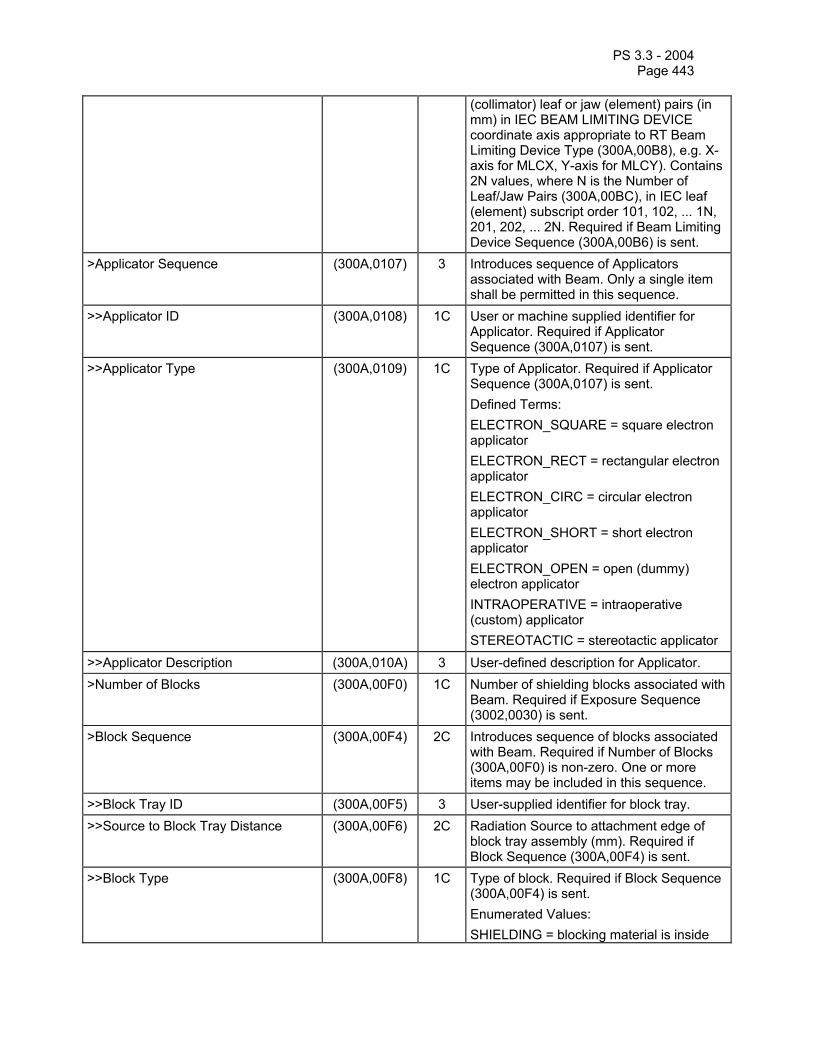
PS 3.3 - 2004 Page 443
(collimator) leaf or jaw (element) pairs (in mm) in IEC BEAM LIMITING DEVICE coordinate axis appropriate to RT Beam Limiting Device Type (300A,00B8), e.g. X-axis for MLCX, Y-axis for MLCY). Contains 2N values, where N is the Number of Leaf/Jaw Pairs (300A,00BC), in IEC leaf (element) subscript order 101, 102, ... 1N, 201, 202, ... 2N. Required if Beam Limiting Device Sequence (300A,00B6) is sent.
>Applicator Sequence (300A,0107) 3 Introduces sequence of Applicators associated with Beam. Only a single item shall be permitted in this sequence.
>>Applicator ID (300A,0108) 1C User or machine supplied identifier for Applicator. Required if Applicator Sequence (300A,0107) is sent.
>>Applicator Type (300A,0109) 1C Type of Applicator. Required if Applicator Sequence (300A,0107) is sent. Defined Terms: ELECTRON_SQUARE = square electron applicator ELECTRON_RECT = rectangular electron applicator ELECTRON_CIRC = circular electron applicator ELECTRON_SHORT = short electron applicator ELECTRON_OPEN = open (dummy) electron applicator INTRAOPERATIVE = intraoperative (custom) applicator STEREOTACTIC = stereotactic applicator
>>Applicator Description (300A,010A) 3 User-defined description for Applicator. >Number of Blocks (300A,00F0) 1C Number of shielding blocks associated with
Beam. Required if Exposure Sequence (3002,0030) is sent.
>Block Sequence (300A,00F4) 2C Introduces sequence of blocks associated with Beam. Required if Number of Blocks (300A,00F0) is non-zero. One or more items may be included in this sequence.
>>Block Tray ID (300A,00F5) 3 User-supplied identifier for block tray. >>Source to Block Tray Distance (300A,00F6) 2C Radiation Source to attachment edge of
block tray assembly (mm). Required if Block Sequence (300A,00F4) is sent.
>>Block Type (300A,00F8) 1C Type of block. Required if Block Sequence (300A,00F4) is sent. Enumerated Values: SHIELDING = blocking material is inside

PS 3.3 - 2004 Page 444
contour APERTURE = blocking material is outside contour
>>Block Divergence (300A,00FA) 2C Indicates presence or otherwise of geometrical divergence. Required if Block Sequence (300A,00F4) is sent. Enumerated Values: PRESENT = block edges are shaped for beam divergence ABSENT = block edges are not shaped for beam divergence
>>Block Mounting Position (300A,00FB) 3 Indicates on which side of the Block Tray the block is mounted. Enumerated Values; PATIENT_SIDE = the block is mounted on the side of the Block Tray which is towards the patient. SOURCE_SIDE = the block is mounted on the side of the Block Tray which is towards the radiation source.
>>Block Number (300A,00FC) 1C Identification Number of the Block. The value of Block Number (300A,00FC) shall be unique within the Beam in which it is created. Required if Block Sequence (300A,00F4) is sent.
>>Block Name (300A,00FE) 3 User-defined name for block. >>Material ID (300A,00E1) 2C User-supplied identifier for material used to
manufacture Block. Required if Block Sequence (300A,00F4) is sent.
>>Block Thickness (300A,0100) 3 Physical thickness of block (in mm) parallel to radiation beam axis.
>>Block Number of Points (300A,0104) 2C Number of (x,y) pairs defining the block edge. Required if Block Sequence (300A,00F4) is sent.
>>Block Data (300A,0106) 2C A data stream of (x,y) pairs which comprise the block edge. The number of pairs shall be equal to Block Number of Points (300A,0104), and the vertices shall be interpreted as a closed polygon. Coordinates are projected onto the machine isocentric plane in the IEC BEAM LIMITING DEVICE coordinate system (mm). Required if Block Sequence (300A,00F4) is sent.
Fluence Map Sequence (3002,0040) 1C A Sequence of data describing the fluence map attributes for a radiotherapy beam. Only one item may be included in this sequence. Required if the third value of Image Type

PS 3.3 - 2004 Page 445
(0008,0008) is FLUENCE. >Fluence Data Source (3002,0041) 1 Source of fluence data.
Enumerated Values: CALCULATED = Calculated by a workstation MEASURED=Measured by exposure to a film or detector.
>Fluence Data Scale (3002,0042) 3 The meterset corresponding with a fluence map cell value of 1.0 expressed in units specified by Primary Dosimeter Units (300A,00B3). This is the meterset value used for treatment, not the meterset used to expose the film as defined by Meterset Exposure (3002,0032).
Gantry Angle (300A,011E) 3 Treatment machine gantry angle, i.e. orientation of IEC GANTRY coordinate system with respect to IEC FIXED REFERENCE coordinate system (degrees).
Beam Limiting Device Angle (300A,0120) 3 Treatment machine beam limiting device (collimator) angle, i.e. orientation of IEC BEAM LIMITING DEVICE coordinate system with respect to IEC GANTRY coordinate system (degrees).
Patient Support Angle (300A,0122) 3 Patient Support angle, i.e. orientation of IEC PATIENT SUPPORT coordinate system with respect to IEC FIXED REFERENCE coordinate system (degrees).
Table Top Eccentric Axis Distance (300A,0124) 3 Distance (positive) from the IEC PATIENT SUPPORT vertical axis to the IEC TABLE TOP ECCENTRIC vertical axis (mm).
Table Top Eccentric Angle (300A,0125) 3 Table Top (non-isocentric) angle, i.e. orientation of IEC TABLE TOP ECCENTRIC coordinate system with respect to IEC PATIENT SUPPORT system (degrees).
Table Top Vertical Position (300A,0128) 3 Table Top Vertical position in IEC TABLE TOP coordinate system (mm).
Table Top Longitudinal Position (300A,0129) 3 Table Top Longitudinal position in IEC TABLE TOP coordinate system (mm).
Table Top Lateral Position (300A,012A) 3 Table Top Lateral position in IEC TABLE TOP coordinate system (mm).
Notes: 1. The numeric beam data parameters recorded with the RT Image correspond to the parameters as they were known at the time the image was created or taken. The parameters may or may not correspond to an actual RT Plan instance that is created for a patient. If the Reported Values Origin (3002,000A) has an enumerated value of OPERATOR or ACTUAL and there is an RT Plan reference present, the numeric beam data parameters may or may not be the same in the two objects.

PS 3.3 - 2004 Page 446
2. The Z coordinate of the X-Ray Image Receptor Translation (3002,000D) will be equal to the Radiation Machine SAD (3002,0022) minus the RT Image SID (3002,0026). If the image receptor is further from the beam source than the machine isocenter, the Z coordinate will be negative (see IEC 61217).
C.8.8.2.1 Multi-frame image data In either multiple exposure multi-frame images or cine images, only the attributes inside of the Exposure Sequence (3002,0030) shall differ between frames. For example, attributes such as beam limiting device (collimator) leaf (element) positions and block information may change, whereas attributes such as gantry and beam limiting device (collimator) angle shall not change.
C.8.8.2.2 X-Ray Image Receptor Angle The X-Ray Image Receptor Angle (3002,000E) specifies the rotation of the image receptor device in the IEC X-RAY IMAGE RECEPTOR PLANE. A positive angle corresponds to a counter-clockwise rotation of the X-Ray Image Receptor as viewed from the radiation source in the IEC GANTRY coordinate system. The normal (non-rotated) value for this parameter is zero degrees.
C.8.8.2.3 Image Plane Pixel Spacing and RT Image SID The Image Plane Pixel Spacing (3002,0011) attribute shall always be defined on the image plane, i.e. at the radiation machine source to image plane distance specified by RT Image SID (3002,0026). For images where the source-image distance is undefined or unknown (e.g. DRR images), RT Image SID (3002,0026) shall equal Radiation Machine SAD (3002,0022) and Image Plane Pixel Spacing (3002,0011) shall be defined on this common plane.
C.8.8.2.4 Exposure Sequence The Exposure Sequence (3002,0030) allows specification of imaging parameters and aperture definitions for single exposure images (single item sequence) or multiple exposures (multiple item sequence). A multiple exposure image can be expressed as a multi-frame image containing either a single frame, or more than one frame. Referenced Frame Number (0008,1160) shall be specified for each Exposure Sequence item for multiple exposure images expressed using more than one frame.
C.8.8.2.5 Single frame and multi-frame images If the Multi-frame Module is present and the Cine Module is not present then the Frame Increment Pointer (0028,0009) shall have the Enumerated Value of 00200013 (Instance Number). If the Multi-frame Module and Cine Module are both present then the Frame Increment Pointer (0028,0009) shall have an Enumerated Value of either 00181063 (Frame Time) or 00181065 (Frame Time Vector).
C.8.8.2.6 Image Pixel Module Attributes C.8.8.2.6.1 Samples per Pixel For RT Images, Samples per Pixel (0028,0002) shall have the Enumerated Value of 0001H.
C.8.8.2.6.2 Photometric Interpretation For RT Images, Photometric Interpretation (0028,0004) shall have the Enumerated Value of MONOCHROME2.
C.8.8.2.6.3 Bits Allocated For RT Images, Bits Allocated (0028,0100) shall have an Enumerated Value of 8 or 16.
C.8.8.2.6.4 Bits Stored For RT Images, Bits Stored (0028,0101) shall have an Enumerated Value of:

PS 3.3 - 2004 Page 447
8 when Bits Allocated (0028,0100) is 8
12-16 when Bits Allocated (0028,0100) is 16
C.8.8.2.6.5 High Bit For RT Images, High Bit (0028,0102) shall have the Enumerated Value of one less than the value sent in Bits Stored (0028,0101).
C.8.8.2.6.6 Pixel Representation For RT Images, Pixel Representation (0028,0103) shall have the Enumerated Value of 0000H (unsigned integer).
C.8.8.3 RT Dose Module The RT Dose module is used to convey 2D or 3D radiation dose data generated from treatment planning systems or similar devices. The attributes defined within the module support dose for a single radiation beam (potentially comprised of multiple segments, as delivered in a dynamic treatment) or a group of beams comprising either a fraction group (see C.8.8.13) or a complete treatment plan (potentially the sum of multiple fraction groups).
The RT Dose module provides the mechanism to transmit a 3D array of dose data as a set of 2D dose planes that may or may not be related to CT or MR image planes. This mechanism works via the DICOM Multi-Frame module which is required if multi-frame pixel data are sent.
Table C.8-39—RT DOSE MODULE ATTRIBUTES Attribute Name Tag Type Attribute Description Samples per Pixel (0028,0002) 1C Number of samples (planes) in this image.
See C.8.8.3.4.1 for specialization. Required if Pixel Data (7FE0,0010) is present.
Photometric Interpretation (0028,0004) 1C Specifies the intended interpretation of the pixel data. See C.8.8.3.4.2 for specialization. Required if Pixel Data (7FE0,0010) is present.
Bits Allocated (0028,0100) 1C Number of bits allocated for each pixel sample. Each sample shall have the same number of bits allocated. See C.8.8.3.4.3 for specialization. Required Pixel Data (7FE0,0010) is present.
Bits Stored (0028,0101) 1C Number of bits stored for each pixel sample. Each sample shall have the same number of bits stored. See C.8.8.3.4.4 for specialization. Required if Pixel Data (7FE0,0010) is present.
High Bit (0028,0102) 1C Most significant bit for each pixel sample. Each sample shall have the same high bit. See C.8.8.3.4.5 for specialization. Required if Pixel Data (7FE0,0010) is present.
Pixel Representation (0028,0103) 1C Data representation of the pixel samples. Each sample shall have the same pixel representation. See C.8.8.3.4.6 for specialization. Required Pixel Data
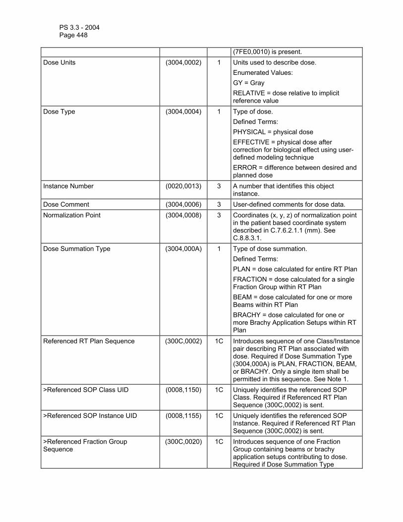
PS 3.3 - 2004 Page 448
(7FE0,0010) is present. Dose Units (3004,0002) 1 Units used to describe dose.
Enumerated Values: GY = Gray RELATIVE = dose relative to implicit reference value
Dose Type (3004,0004) 1 Type of dose. Defined Terms: PHYSICAL = physical dose EFFECTIVE = physical dose after correction for biological effect using user-defined modeling technique ERROR = difference between desired and planned dose
Instance Number (0020,0013) 3 A number that identifies this object instance.
Dose Comment (3004,0006) 3 User-defined comments for dose data. Normalization Point (3004,0008) 3 Coordinates (x, y, z) of normalization point
in the patient based coordinate system described in C.7.6.2.1.1 (mm). See C.8.8.3.1.
Dose Summation Type (3004,000A) 1 Type of dose summation. Defined Terms: PLAN = dose calculated for entire RT Plan FRACTION = dose calculated for a single Fraction Group within RT Plan BEAM = dose calculated for one or more Beams within RT Plan BRACHY = dose calculated for one or more Brachy Application Setups within RT Plan
Referenced RT Plan Sequence (300C,0002) 1C Introduces sequence of one Class/Instance pair describing RT Plan associated with dose. Required if Dose Summation Type (3004,000A) is PLAN, FRACTION, BEAM, or BRACHY. Only a single item shall be permitted in this sequence. See Note 1.
>Referenced SOP Class UID (0008,1150) 1C Uniquely identifies the referenced SOP Class. Required if Referenced RT Plan Sequence (300C,0002) is sent.
>Referenced SOP Instance UID (0008,1155) 1C Uniquely identifies the referenced SOP Instance. Required if Referenced RT Plan Sequence (300C,0002) is sent.
>Referenced Fraction Group Sequence
(300C,0020) 1C Introduces sequence of one Fraction Group containing beams or brachy application setups contributing to dose. Required if Dose Summation Type

PS 3.3 - 2004 Page 449
(3004,000A) is FRACTION, BEAM, or BRACHY. Only a single item shall be permitted in this sequence. See Note 1.
>>Referenced Fraction Group Number (300C,0022) 1C Uniquely identifies Fraction Group specified by Fraction Group Number (300A,0071) in Fraction Group Sequence of RT Fraction Scheme Module within RT Plan referenced in Referenced RT Plan Sequence (300C,0002). Required if Referenced Fraction Group Sequence (300C,0020) is sent.
>>Referenced Beam Sequence (300C,0004) 1C Introduces sequence of Beams in current Fraction Group contributing to dose. Required if Dose Summation Type (3004,000A) is BEAM. One or more items may be included in this sequence.
>>>Referenced Beam Number (300C,0006) 1C Uniquely identifies Beam specified by Beam Number (300A,00C0) in Beam Sequence of RT Beams Module within RT Plan referenced in Referenced RT Plan Sequence (300C,0002). Required if Referenced Beam Sequence (300A,0004) is sent.
>>Referenced Brachy Application Setup Sequence
(300C,000A) 1C Introduces sequence of Brachy Application Setups in current Fraction Group contributing to dose. Required if Dose Summation Type (3004,000A) is BRACHY. One or more items may be included in this sequence.
>>>Referenced Brachy Application Setup Number
(300C,000C) 1C Uniquely identifies Brachy Application Setup specified by Brachy Application Setup Number (300A,0234) in Brachy Application Setup Sequence (300A,0230) of RT Brachy Application Setups Module within RT Plan referenced in Referenced RT Plan Sequence (300C,0002). Required if Referenced Brachy Application Setup Sequence (300C,000A) is sent.
Grid Frame Offset Vector (3004,000C) 1C An array which contains the z coordinates (in mm) of the image frames in a multi-frame dose. Required if multi-frame pixel data are present and Frame Increment Pointer (0028,0009) points to Grid Frame Offset Vector (3004,000C). See C.8.8.3.2.
Dose Grid Scaling (3004,000E) 1 Scaling factor that when multiplied by the dose grid data found in the Pixel Data (7FE0,0010) attribute of the Image Pixel Module, yields grid doses in the dose units as specified by Dose Units (3004,0002).
Tissue Heterogeneity Correction (3004,0014) 3 Specifies a list of patient heterogeneity characteristics used for calculating dose. This Atttibute shall be multi-valued if

PS 3.3 - 2004 Page 450
beams used to compute the dose have differing correction techniques. Enumerated Values: IMAGE = image data ROI_OVERRIDE = one or more
ROI densities override image or water values where they exist
WATER = entire volume treated as water equivalent
Note: In order to prevent misrepresentation of dose summation components, if the Dose Summation Type (3004,000A) is PLAN then only a single instance of RT Plan is referenced (i.e. component fraction groups are not referenced). Similarly, if the Dose Summation Type (3004,000A) is FRACTION then only a single instance of RT Plan and a single Fraction Group are referenced (i.e. component beams or brachy application setups are not referenced).
C.8.8.3.1 Normalization Point The Normalization Point (3004,0008) aids in the interpretation and subsequent use of the transmitted data. If used, it shall be a point receiving dose contributions from all referenced components of the dose summation.
C.8.8.3.2 Grid Frame Offset Vector Grid Frame Offset Vector (3004,000C) shall be provided if a dose distribution is sent as a multi-frame image. This attribute contains an array of n elements indicating the plane location of the data. This attribute is conditional since the RT Dose module may be included even if pixel doses are not being transmitted, or the image may be a single-frame image. If the Multi-frame Module is present, Frame Increment Pointer (0028,0009) shall have the Enumerated Value of 3004000C (Grid Frame Offset Vector).
C.8.8.3.3 Dose Units Dose Units are specified in both the RT Dose and RT Dose ROI modules. The attribute Dose Type present in the RT Dose module shall apply to all doses present in the RT Dose IOD.
C.8.8.3.4 Image Pixel Module Attributes C.8.8.3.4.1 Samples per Pixel For RT Doses, Samples per Pixel (0028,0002) shall have the Enumerated Value of 1.
C.8.8.3.4.2 Photometric Interpretation For RT Doses, Photometric Interpretation (0028,0004) shall have the Enumerated Value of MONOCHROME2.
C.8.8.3.4.3 Bits Allocated For RT Doses, Bits Allocated (0028,0100) shall have an Enumerated Value of 16 or 32.
C.8.8.3.4.4 Bits Stored For RT Doses, Bits Stored (0028,0101) shall have an Enumerated Value equal to Bits Allocated (0028,0100).
C.8.8.3.4.5 High Bit For RT Doses, High Bit (0028,0102) shall have the Enumerated Value of one less than the value sent in Bits Stored (0028,0101).

PS 3.3 - 2004 Page 451
C.8.8.3.4.6 Pixel Representation For RT Doses, Pixel Representation (0028,0103) is specified to use the following Enumerated Values:
0001H = two’s complement integer, when Dose Type (3004,0004) = ERROR 0000H = unsigned integer, otherwise.
C.8.8.4 RT DVH Module The RT DVH module provides for the inclusion of differential or cumulative dose volume histogram data. The data contained within this module may supplement dose data in the RT Dose and/or RT Dose ROI modules, or it may be present in the absence of other dose data.
Table C.8-40—RT DVH MODULE ATTRIBUTES Attribute Name Tag Type Attribute Description Referenced Structure Set Sequence (300C,0060) 1 Introduces sequence of one class/instance
pair describing Structure Set containing structures which are used to calculate Dose-Volume Histograms (DVHs). Only a single item shall be permitted in this sequence. See C.8.8.4.1.
>Referenced SOP Class UID (0008,1150) 1 Uniquely identifies the referenced SOP Class.
>Referenced SOP Instance UID (0008,1155) 1 Uniquely identifies the referenced SOP Instance.
DVH Normalization Point (3004,0040) 3 Coordinates (x, y, z) of common DVH normalization point in the patient based coordinate system described in C.7.6.2.1.1 (mm).
DVH Normalization Dose Value (3004,0042) 3 Dose Value at DVH Normalization Point (3004,0040) used as reference for individual DVHs when Dose Units (3004,0002) is RELATIVE.
DVH Sequence (3004,0050) 1 Introduces sequence of DVHs. One or more items may be included in this sequence.
>DVH Referenced ROI Sequence (3004,0060) 1 Introduces sequence of referenced ROIs used to calculate DVH.
>>Referenced ROI Number (3006,0084) 1 Uniquely identifies ROI used to calculate DVH specified by ROI Number (3006,0022) in Structure Set ROI Sequence (3006,0020) in Structure Set Module within RT Structure Set referenced by referenced RT Plan in Referenced RT Plan Sequence (300C,0002) in RT Dose Module.
>>DVH ROI Contribution Type (3004,0062) 1 Specifies whether volume within ROI is included or excluded in DVH. See C.8.8.4.2. Enumerated Values: INCLUDED, EXCLUDED.
>DVH Type (3004,0001) 1 Type of DVH. Enumerated Values:

PS 3.3 - 2004 Page 452
DIFFERENTIAL = differential dose-volume histogram CUMULATIVE = cumulative dose-volume histogram NATURAL = natural dose volume histogram
>Dose Units (3004,0002) 1 Dose axis units. Enumerated Values: GY = Gray RELATIVE = dose relative to reference value specified in DVH Normalization Dose Value (3004,0042)
>Dose Type (3004,0004) 1 Type of dose. Defined Terms: PHYSICAL = physical dose EFFECTIVE = physical dose after correction for biological effect using user-defined modeling technique ERROR = difference between desired and planned dose
>DVH Dose Scaling (3004,0052) 1 Scaling factor that when multiplied by the dose bin widths found in DVH Data (3004,0058), yields dose bin widths in the dose units as specified by Dose Units (3004,0002).
>DVH Volume Units (3004,0054) 1 Volume axis units. Defined Terms: CM3 = cubic centimeters PERCENT = percent PER_U= volume per u with u(dose)=dose-
3/2. See C.8.8.4.3. >DVH Number of Bins (3004,0056) 1 Number of bins n used to store DVH Data
(3004,0058). >DVH Data (3004,0058) 1 A data stream describing the dose bin
widths Dn and associated volumes Vn in DVH Volume Units (3004,0054) in the order D1V1, D2V2, ... DnVn.
>DVH Minimum Dose (3004,0070) 3 Minimum calculated dose to ROI(s) described by DVH Referenced ROI Sequence (3004,0060).
>DVH Maximum Dose (3004,0072) 3 Maximum calculated dose to ROI(s) described by DVH Referenced ROI Sequence (3004,0060).
>DVH Mean Dose (3004,0074) 3 Mean calculated dose to ROI(s) described by DVH Referenced ROI Sequence (3004,0060).

PS 3.3 - 2004 Page 453
C.8.8.4.1 Referenced Structure Set Sequence The Referenced Structure Set Sequence (300C,0060) is required for direct cross-reference of the dose bin data with the corresponding ROI(s) from which they were derived. ROIs referenced by the DVH Referenced ROI Sequence (3004,0050) shall only contain contours with a Contour Geometric Type (3006,0042) of POINT or CLOSED_PLANAR.
C.8.8.4.2 DVH ROI Contribution Type The volume used to calculate the DVH shall be the geometric union of ROIs where DVH ROI Contribution Type (3004,0062) is INCLUDED, minus the geometric union of ROIs where DVH ROI Contribution Type (3004,0062) is EXCLUDED.
C.8.8.4.3 DVH Volume Units The unit PER_U is defined in: Anderson, LL: “A “natural” volume-dose histogram for brachytherapy”, Medical Physics 13(6) pp 898-903, 1986.
C.8.8.5 Structure Set Module A structure set defines a set of areas of significance. Each area can be associated with a Frame of Reference and zero or more images. Information that can be transferred with each region of interest (ROI) includes geometrical and display parameters, and generation technique.
Table C.8-41—STRUCTURE SET MODULE ATTRIBUTES Attribute Name Tag Type Attribute Description Structure Set Label (3006,0002) 1 User-defined label for Structure Set. Structure Set Name (3006,0004) 3 User-defined name for Structure Set. Structure Set Description (3006,0006) 3 User-defined description for Structure Set. Instance Number (0020,0013) 3 A number that identifies this object
instance. Structure Set Date (3006,0008) 2 Date at which Structure Set was last
modified. Structure Set Time (3006,0009) 2 Time at which Structure Set was last
modified. Referenced Frame of Reference Sequence
(3006,0010) 3 Introduces sequence of items describing Frames of Reference in which the ROIs are defined. One or more items may be included in this sequence. See C.8.8.5.1.
>Frame of Reference UID (0020,0052) 1C Uniquely identifies Frame of Reference within Structure Set. Required if Referenced Frame of Reference Sequence (3006,0010) is sent.
>Frame of Reference Relationship Sequence
(3006,00C0) 3 Introduces sequence of transforms that relate other Frames of Reference to this Frame of Reference.
>>Related Frame of Reference UID (3006,00C2) 1C Frame of Reference Coordinate System to be transformed to the current Frame of Reference. Required if Frame of Reference Relationship Sequence (3006,00C0) is sent.
>>Frame of Reference Transformation (3006,00C4) 1C Type of Transformation. Required if Frame

PS 3.3 - 2004 Page 454
Type of Reference Relationship Sequence (3006,00C0) is sent. Defined Terms: HOMOGENEOUS
>>Frame of Reference Transformation Matrix
(3006,00C6) 1C Four-by-four transformation Matrix from Related Frame of Reference to current Frame of Reference. Matrix elements shall be listed in row-major order. Required if Frame of Reference Relationship Sequence (3006,00C0) is sent. See C.8.8.5.2.
>>Frame of Reference Transformation Comment
(3006,00C8) 3 Comment regarding the transformation between the related and current Frames of Reference.
>RT Referenced Study Sequence (3006,0012) 3 Introduces sequence of Studies containing series to be referenced. One or more items may be included in this sequence.
>>Referenced SOP Class UID (0008,1150) 1C Uniquely identifies the referenced SOP Class. Required if RT Referenced Study Sequence (3006,0012) is sent.
>>Referenced SOP Instance UID (0008,1155) 1C Uniquely identifies the referenced SOP Instance. Required if RT Referenced Study Sequence (3006,0012) is sent.
>>RT Referenced Series Sequence (3006,0014) 1C Introduces sequence of items describing series of images within the referenced study which are used in defining the Structure Set. Required if RT Referenced Study Sequence (3006,0012) is sent. One or more items may be included in this sequence.
>>>Series Instance UID (0020,000E) 1C Unique identifier for the series containing the images. Required if RT Referenced Series Sequence (3006,0014) is sent.
>>>Contour Image Sequence (3006,0016) 1C Introduces sequence of items describing images in a given series used in defining the Structure Set (typically CT or MR images). Required if RT Referenced Series Sequence (3006,0014) is sent. One or more items may be included in this sequence.
>>>>Referenced SOP Class UID (0008,1150) 1C Uniquely identifies the referenced image SOP Class. Required if Contour Image Sequence (3006,0016) is sent.
>>>>Referenced SOP Instance UID (0008,1155) 1C Uniquely identifies the referenced image SOP Instance. Required if Contour Image Sequence (3006,0016) is sent.
>>>>Referenced Frame Number (0008,1160) 3 Identifies image frame if a multi-frame image is referenced.
Structure Set ROI Sequence (3006,0020) 3 Introduces sequence of ROIs for current Structure Set. One or more items may be

PS 3.3 - 2004 Page 455
included in this sequence. >ROI Number (3006,0022) 1C Identification number of the ROI. The value
of ROI Number (3006,0022) shall be unique within the Structure Set in which it is created. Required if Structure Set ROI Sequence (3006,0020) is sent.
>Referenced Frame of Reference UID (3006,0024) 1C Uniquely identifies Frame of Reference in which ROI is defined, specified by Frame of Reference UID (0020,0052) in Referenced Frame of Reference Sequence (3006,0010). Required if Structure Set ROI Sequence (3006,0020) is sent.
>ROI Name (3006,0026) 2C User-defined name for ROI. Required if Structure Set ROI Sequence (3006,0020) is sent.
>ROI Description (3006,0028) 3 User-defined description for ROI. >ROI Volume (3006,002C) 3 Volume of ROI (cubic centimeters). >ROI Generation Algorithm (3006,0036) 2C Type of algorithm used to generate ROI.
Required if Structure Set ROI Sequence (3006,0020) is sent. Defined Terms: AUTOMATIC = calculated ROI SEMIAUTOMATIC = ROI calculated with user assistance MANUAL = user-entered ROI
>ROI Generation Description (3006,0038) 3 User-defined description of technique used to generate ROI.
C.8.8.5.1 Frames of Reference The Referenced Frame of Reference Sequence (3006,0010) describes a set of frames of reference in which some or all of the ROIs are expressed. Since the Referenced Frame of Reference UID (3006,0024) is required for each ROI, each frame of reference used to express the coordinates of an ROI shall be listed in the Referenced Frame of Reference Sequence (3006,0010) once and only once.
Notes: 1.As an example, a set of ROIs defined using a single image series would list the image series in a single Referenced Frame of Reference Sequence (3006,0010) item, providing the UID for this referenced frame of reference (obtained from the source images), and listing all pertinent images in the Contour Image Sequence (3006,0016).
2. As an example, a set of ROIs containing ROIs referencing more than one frame of reference would list the referenced images in two or more different Referenced Frame of Reference Sequence (3006,0010) items, providing in each case the UID for this referenced frame of reference (obtained from the source images), and listing all pertinent images in the Contour Image Sequence (3006,0016). Each ROI would then reference the appropriate Frame of Reference UID (0020,0052).
C.8.8.5.2 Frame of Reference Transformation Matrix In a rigid body system, two coordinate systems can be related using a single 4 x 4 transformation matrix to describe any rotations and/or translations necessary to transform coordinates from the related coordinate system (frame of reference) to the primary system. The equation performing

PS 3.3 - 2004 Page 456
the transform from a point (X’,Y’,Z’) in the related coordinate system to a point (X,Y,Z) in the current coordinate system can be shown as follows, where for homogeneous transforms M41 = M42 = M43 = 0 and M44 = 1:
X M11 M12 M13 M14 X’
Y = M21 M22 M23 M24 x Y’
Z M31 M32 M33 M34 Z’
1 M41 M42 M43 M44 1

PS 3.3 - 2004 Page 457
C.8.8.6 ROI Contour Module In general, a ROI can be defined by either a sequence of overlays or a sequence of contours. This module, if present, is used to define the ROI as a set of contours. Each ROI contains a sequence of one or more contours, where a contour is either a single point (for a point ROI) or more than one point (representing an open or closed polygon).
Table C.8-42—ROI CONTOUR MODULE ATTRIBUTES Attribute Name Tag Type Attribute Description ROI Contour Sequence (3006,0039) 1 Introduces sequence of Contour
Sequences defining ROIs. One or more items may be included in this sequence.
>Referenced ROI Number (3006,0084) 1 Uniquely identifies the referenced ROI described in the Structure Set ROI Sequence (3006,0020).
>ROI Display Color (3006,002A) 3 RGB triplet color representation for ROI, specified using the range 0-255.
>Contour Sequence (3006,0040) 3 Introduces sequence of Contours defining ROI. One or more items may be included in this sequence.
>>Contour Number (3006,0048) 3 Identification number of the contour. The value of Contour Number (3006,0048) shall be unique within the Contour Sequence (3006,0040) in which it is defined. No semantics or ordering shall be inferred from this attribute.
>>Attached Contours (3006,0049) 3 List of Contour Number (3006,0048) defining lower-numbered contour(s) to which the current contour is connected.
>>Contour Image Sequence (3006,0016) 3 Introduces sequence of images containing the contour. One or more items may be included in this sequence.
>>>Referenced SOP Class UID (0008,1150) 1C Uniquely identifies the referenced image SOP Class of the image containing the Contour, if it exists. Required if Contour Image Sequence (3006,0016) is sent.
>>>Referenced SOP Instance UID (0008,1155) 1C Uniquely identifies the referenced image SOP Instance of the image containing the Contour, if it exists. Required if Contour Image Sequence (3006,0016) is sent.
>>>Referenced Frame Number (0008,1160) 1C Identifies image frame if a multi-frame image is referenced. Required if referenced image is a multi-frame image.
>>Contour Geometric Type (3006,0042) 1C Geometric type of contour. Required if Contour Sequence (3006,0040) is sent. See C.8.8.6.1. Enumerated Values: POINT = single point OPEN_PLANAR = open contour containing coplanar points

PS 3.3 - 2004 Page 458
OPEN_NONPLANAR = open contour containing non-coplanar points CLOSED_PLANAR = closed contour (polygon) containing coplanar points
>>Contour Slab Thickness (3006,0044) 3 Thickness of slab (in mm) represented by contour, where the Contour Data (3006,0050) defines a plane in the center of the slab, offset by the Contour Offset Vector (3006,0045) if it is present. See C.8.8.6.2.
>>Contour Offset Vector (3006,0045) 3 Vector (x,y,z) in the the patient based coordinate system described in C.7.6.2.1.1 which is normal to plane of Contour Data (3006,0050), describing direction and magnitude of the offset (in mm) of each point of the central plane of a contour slab from the corresponding original point of Contour Data (3006,0050). See C.8.8.6.2.
>>Number of Contour Points (3006,0046) 1C Number of points (triplets) in Contour Data (3006,0050). Required if Contour Sequence (3006,0040) is sent.
>>Contour Data (3006,0050) 1C Sequence of (x,y,z) triplets defining a contour in the patient based coordinate system described in C.7.6.2.1.1 (mm). Required if Contour Sequence (3006,0040) is sent. See C.8.8.6.1 and C.8.8.6.3.
C.8.8.6.1 Contour Geometric Type A contour can be one of the following geometric types:
- A Contour Geometric Type (3006,0042) of POINT indicates that the contour is a single point, defining a specific location of significance.
- A Contour Geometric Type (3006,0042) of OPEN_PLANAR indicates that the last vertex shall not be connected to the first point, and that all points in Contour Data (3006,0050) shall be coplanar.
- A Contour Geometric Type (3006,0042) of OPEN_NONPLANAR indicates that the last vertex shall not be connected to the first point, and that the points in Contour Data (3006,0050) may be non-coplanar. Contours having a Geometric Type (3006,0042) of OPEN_NONPLANAR can be used to represent objects best described by a single, possibly non-coplanar curve, such as a brachytherapy applicator.
- A Contour Geometric Type (3006,0042) of CLOSED_PLANAR indicates that the last point shall be connected to the first point, where the first point is not repeated in the Contour Data (3006,0050). All points in Contour Data (3006,0050) shall be coplanar.
C.8.8.6.2 Contour Slab Thickness A set of Contour slabs may define a multi-slab Volume of Interest. Contour Slab Thickness (3006,0044) shall specify the thickness of a slab, the central plane of which shall be defined by

PS 3.3 - 2004 Page 459
the set of points offset from Contour Data (3006,0050) by the value of Contour Offset Vector (3006,0045). One contour slab may contain one to many sets of Contour Data (3006,0050) that may define regions of one complex Volume of Interest. If no valid value of Contour Slab Thickness (3006,0044) is sent, then the offset value shall be (0,0,0) and the original Contour Data (3006,0050) shall define the central plane of the Contour slab.
C.8.8.6.3 Representing Inner and Outer Contours on an Image When a single ROI describes an excluded inner volume, this can be encoded with a single contour, using a “keyhole” technique. In this method, an arbitrarily narrow channel is used to connect the outer contour to the inner contour, so that it is drawn as a single contour. An example of such a structure is shown in Figure C.8.8.6-1
Points in space lying along the path defined by the contour are considered to be inside the ROI.
Figure C.8.8.6-1 Example of ROI with excluded inner volume
C.8.8.7 RT Dose ROI Module RT Dose ROI provides ancillary dose-related information to the ROI data defined within the Structure Set and ROI Contour modules, which may be included in the RT Dose IOD composite object. These modules in combination provide for the definition of dose data in the form of isodose curves or named or unnamed dose points. Isodose curves in radiation oncology are simply contours identifying a set of points with the same dose value.
Table C.8-43—RT DOSE ROI MODULE ATTRIBUTES Attribute Name Tag Type Attribute Description RT Dose ROI Sequence (3004,0010) 1 Introduces sequence of items specifying
dose levels for isodose curves or dose points described in the ROI module. One or more items may be included in this sequence. See C.8.8.7.1.
>Referenced ROI Number (3006,0084) 1 Uniquely identifies the referenced ROI within the current RT Dose. See Note 1 and C.8.8.7.2.
>Dose Units (3004,0002) 1 Units used for ROI Dose. Enumerated Values: GY = Gray RELATIVE = dose relative to implicit reference value
>Dose Value (3004,0012) 1 Dose value for ROI, in units defined by

PS 3.3 - 2004 Page 460
Dose Units (3004,0002). See C.8.8.7.3.
Notes: 1. The Structure Set ROI Sequence (3006,0020) defining the dose point and surfaces is defined in the Structure Set module. The ROI Number (3006,0022) attribute is unique within the Structure Set ROI Sequence, and is referenced from the RT Dose ROI module using Referenced ROI Number (3006,0084).
2. The RT Dose ROI module defines the attributes that describe references to ROIs contained within the associated Structure Set and RT ROI Contour modules. Note that the RT Dose module table specifies that either all or none of the modules Structures Set, ROI Contour, and RT Dose ROI must be present in the RT Dose IOD.
C.8.8.7.1 Contour Geometric Type of Referenced ROI ROIs referenced in the RT Dose ROI Module shall have a Contour Geometric Type (3006,0042) of POINT, OPEN_PLANAR or CLOSED_PLANAR.
C.8.8.7.2 Referenced ROI Number There shall be a one-to-one correspondence between Referenced ROI Number (3006,0084) and the sequence of ROIs defined in the Structure Set and ROI Contour modules. The RT Dose ROI module shall only contain references to structures which are dose-related (i.e. dose points and isodose curves).
C.8.8.7.3 Dose Value Dose Value (3004,0012) shall be the dose value corresponding to the referenced isodose curve, named dose point, or unnamed dose point.
C.8.8.8 RT ROI Observations Module The RT ROI Observations module specifies the identification and interpretation of an ROI specified in the Structure Set and ROI Contour modules.
Table C.8-44—RT ROI OBSERVATIONS MODULE ATTRIBUTES Attribute Name Tag Type Attribute Description RT ROI Observations Sequence (3006,0080) 1 Introduces sequence of observations
related to ROIs defined in the ROI Module. One or more items may be included in this sequence.
>Observation Number (3006,0082) 1 Identification number of the Observation. The value of Observation Number (3006,0082) shall be unique within the RT ROI Observations Sequence (3006,0080).
>Referenced ROI Number (3006,0084) 1 Uniquely identifies the referenced ROI described in the Structure Set ROI Sequence (3006,0020).
>ROI Observation Label (3006,0085) 3 User-defined label for ROI Observation. >ROI Observation Description (3006,0088) 3 User-defined description for ROI
Observation. >RT Related ROI Sequence (3006,0030) 3 Introduces sequence of significantly related
ROIs, e.g. CTVs contained within a PTV. One or more items may be included in this sequence.
>>Referenced ROI Number (3006,0084) 1C Uniquely identifies the related ROI
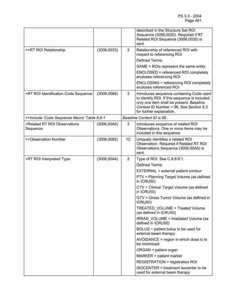
PS 3.3 - 2004 Page 461
described in the Structure Set ROI Sequence (3006,0020). Required if RT Related ROI Sequence (3006,0030) is sent.
>>RT ROI Relationship (3006,0033) 3 Relationship of referenced ROI with respect to referencing ROI. Defined Terms: SAME = ROIs represent the same entity ENCLOSED = referenced ROI completely encloses referencing ROI ENCLOSING = referencing ROI completely encloses referenced ROI
>RT ROI Identification Code Sequence (3006,0086) 3 Introduces sequence containing Code used to identify ROI. If this sequence is included, only one item shall be present. Baseline Context ID Number = 96. See Section 5.3 for further explanation.
>>Include ‘Code Sequence Macro’ Table 8.8-1 Baseline Context ID is 96 . >Related RT ROI Observations Sequence
(3006,00A0) 3 Introduces sequence of related ROI Observations. One or more items may be included in this sequence.
>>Observation Number (3006,0082) 1C Uniquely identifies a related ROI Observation. Required if Related RT ROI Observations Sequence (3006,00A0) is sent.
>RT ROI Interpreted Type (3006,00A4) 2 Type of ROI. See C.8.8.8.1. Defined Terms: EXTERNAL = external patient contour PTV = Planning Target Volume (as defined in ICRU50) CTV = Clinical Target Volume (as defined in ICRU50) GTV = Gross Tumor Volume (as defined in ICRU50) TREATED_VOLUME = Treated Volume (as defined in ICRU50) IRRAD_VOLUME = Irradiated Volume (as defined in ICRU50) BOLUS = patient bolus to be used for external beam therapy AVOIDANCE = region in which dose is to be minimized ORGAN = patient organ MARKER = patient marker REGISTRATION = registration ROI ISOCENTER = treatment isocenter to be used for external beam therapy

PS 3.3 - 2004 Page 462
CONTRAST_AGENT = volume into which a contrast agent has been injected CAVITY = patient anatomical cavity BRACHY_CHANNEL = brachytherapy channel BRACHY_ACCESSORY = brachytherapy accessory device BRACHY_SRC_APP = brachytherapy source applicator BRACHY_CHNL_SHLD = brachytherapy channel shield
>ROI Interpreter (3006,00A6) 2 Name of person performing the interpretation.
>Material ID (300A,00E1) 3 User-supplied identifier for ROI material. >ROI Physical Properties Sequence (3006,00B0) 3 Introduces sequence describing physical
properties associated with current ROI interpretation. One or more items may be included in this sequence.
>>ROI Physical Property (3006,00B2) 1C Physical property specified by ROI Physical Property Value (3006,00B4). Required if ROI Physical Properties Sequence (3006,00B0) is sent. Defined Terms: REL_MASS_DENSITY = mass density relative to water REL_ELEC_DENSITY = electron density relative to water EFFECTIVE_Z = effective atomic number EFF_Z_PER_A = effective ratio of atomic number to mass (AMU-1)
>>ROI Physical Property Value (3006,00B4) 1C User-assigned value for physical property. Required if ROI Physical Properties Sequence (3006,00B0) is sent.
C.8.8.8.1 RT ROI Interpreted Type RT ROI Interpreted Type (3006,00A4) shall describe the class of ROI (e.g. CTV, PTV). Individual instances of each class of structure (e.g. CTV1, CTV2) can be distinguished using ROI Observation Label (3006,0085).
C.8.8.9 RT General Plan Module Table C.8-45—RT GENERAL PLAN MODULE ATTRIBUTES
Attribute Name Tag Type Attribute Description RT Plan Label (300A,0002) 1 User-defined label for treatment plan. RT Plan Name (300A,0003) 3 User-defined name for treatment plan. RT Plan Description (300A,0004) 3 User-defined description of treatment plan. Instance Number (0020,0013) 3 A number that identifies this object

PS 3.3 - 2004 Page 463
instance. Operators’ Name (0008,1070) 2 Name of operator(s) creating treatment
plan. RT Plan Date (300A,0006) 2 Date treatment plan was last modified. RT Plan Time (300A,0007) 2 Time treatment plan was last modified. Treatment Protocols (300A,0009) 3 Planned treatment protocols. Treatment Intent (300A,000A) 3 Intent of this course of treatment.
Defined Terms: CURATIVE PALLIATIVE PROPHYLACTIC VERIFICATION
Treatment Sites (300A,000B) 3 Planned treatment sites. RT Plan Geometry (300A,000C) 1 Describes whether RT Plan is based on
patient or treatment device geometry. See C.8.8.9.1. Defined Terms: PATIENT = RT Structure Set exists TREATMENT_DEVICE = RT Structure Set does not exist
Referenced Structure Set Sequence (300C,0060) 1C Introduces sequence of one Class/Instance pair describing instance of RT Structure Set on which the RT Plan is based. Only a single item shall be permitted in this sequence. Required if RT Plan Geometry (300A,000C) is PATIENT.
>Referenced SOP Class UID (0008,1150) 1C Uniquely identifies the referenced SOP Class. Required if Referenced Structure Set Sequence (300C,0060) is sent.
>Referenced SOP Instance UID (0008,1155) 1C Uniquely identifies the referenced SOP Instance. Required if Referenced Structure Set Sequence (300C,0060) is sent.
Referenced Dose Sequence (300C,0080) 3 Introduces sequence of related SOP Class/Instance pairs describing related instances of RT Dose (for grids and named/unnamed point doses). One or more items may be included in this sequence. See Note 1.
>Referenced SOP Class UID (0008,1150) 1C Uniquely identifies the referenced SOP Class. Required if Referenced RT Dose Sequence (300C,0080) is sent.
>Referenced SOP Instance UID (0008,1155) 1C Uniquely identifies the referenced SOP Instance. Required if Referenced RT Dose Sequence (300C,0080) is sent.
Referenced RT Plan Sequence (300C,0002) 3 Introduces sequence of related SOP Class/Instance pairs describing related instances of RT Plan. One or more items

PS 3.3 - 2004 Page 464
may be included in this sequence. >Referenced SOP Class UID (0008,1150) 1C Uniquely identifies the referenced SOP
Class. Required if Referenced RT Plan Sequence (300C,0002) is sent.
>Referenced SOP Instance UID (0008,1155) 1C Uniquely identifies the referenced SOP Instance. Required if Referenced RT Plan Sequence (300C,0002) is sent.
>RT Plan Relationship (300A,0055) 1C Relationship of referenced plan with respect to current plan. Required if Referenced RT Plan Sequence (300C,0002) is sent. Defined Terms: PRIOR = plan delivered prior to current treatment ALTERNATIVE = alternative plan prepared for current treatment PREDECESSOR = plan used in derivation of current plan VERIFIED_PLAN = plan which is verified using the current plan. This value shall only be used if Treatment Intent (300A,000A) is present and has a value of VERIFICATION.
Note: An RT Dose IOD referenced within the Referenced Dose Sequence (300C,0080) can be used for storing grid-based (pixel) data, individual dose points (with optional dose point names), isodose curves, and DVH's.
C.8.8.9.1 Referenced Structure Set Sequence An RT Plan Geometry (300A,000C) of PATIENT shall signify that an RT Structure Set has been defined upon which the plan geometry is based, and this RT Structure Set shall be specified in the Referenced Structure Set Sequence (300C,0060). An RT Plan Geometry (300A,000C) of TREATMENT_DEVICE shall indicate that no patient geometry is available, and that the RT Plan is being defined with respect to the IEC FIXED Coordinate System.
C.8.8.10 RT Prescription Module Table C.8-46—RT PRESCRIPTION MODULE ATTRIBUTES
Attribute Name Tag Type Attribute Description Prescription Description (300A,000E) 3 User-defined description of treatment
prescription. Dose Reference Sequence (300A,0010) 3 Introduces sequence of Dose References.
One or more items may be included in this sequence.
>Dose Reference Number (300A,0012) 1C Identification number of the Dose Reference. The value of Dose Reference Number (300A,0012) shall be unique within the RT Plan in which it is created. Required if Dose Reference Sequence (300A,0012)

PS 3.3 - 2004 Page 465
is sent. >Dose Reference UID (300A,0013) 3 A unique identifier for a Dose Reference
that can be used to link the same entity across multiple RT Plan objects.
>Dose Reference Structure Type (300A,0014) 1C Structure type of Dose Reference. Required if Dose Reference Sequence (300A,0010) is sent. Defined Terms: POINT = dose reference point specified as ROI VOLUME = dose reference volume specified as ROI COORDINATES = point specified by Dose Reference Point Coordinates (300A,0018) SITE = dose reference clinical site
>Dose Reference Description (300A,0016) 3 User-defined description of Dose Reference.
>Referenced ROI Number (3006,0084) 1C Uniquely identifies ROI representing the dose reference specified by ROI Number (3006,0022) in Structure Set ROI Sequence (3006,0020) in Structure Set Module within RT Structure Set in Referenced Structure Set Sequence (300C,0060) in RT General Plan Module. Required if Dose Reference Structure Type (300A,0014) is POINT or VOLUME and Dose Reference Sequence (300A,0010) is sent.
>Dose Reference Point Coordinates (300A,0018) 1C Coordinates (x,y,z) of Reference Point in the patient based coordinate system described in C.7.6.2.1.1 (mm). Required if Dose Reference Structure Type (300A,0014) is COORDINATES and Dose Reference Sequence (300A,0010) is sent.
>Nominal Prior Dose (300A,001A) 3 Dose (in Gy) from prior treatment to this Dose Reference (e.g. from a previous course of treatment).
>Dose Reference Type (300A,0020) 1C Type of Dose Reference. Required if Dose Reference Sequence (300A,0010) is sent. Defined Terms: TARGET = treatment target (corresponding to GTV, PTV, or CTV in ICRU50) ORGAN_AT_RISK = Organ at Risk (as defined in ICRU50)
>Constraint Weight (300A,0021) 3 Relative importance of satisfying constraint, where high values represent more important constraints.
>Delivery Warning Dose (300A,0022) 3 The dose (in Gy) which when reached or exceeded should cause some action to be

PS 3.3 - 2004 Page 466
taken. >Delivery Maximum Dose (300A,0023) 3 The maximum dose (in Gy) which can be
delivered to the dose reference. >Target Minimum Dose (300A,0025) 3 Minimum permitted dose (in Gy) to Dose
Reference if Dose Reference Type (300A,0020) is TARGET.
>Target Prescription Dose (300A,0026) 3 Prescribed dose (in Gy) to Dose Reference if Dose Reference Type (300A,0020) is TARGET.
>Target Maximum Dose (300A,0027) 3 Maximum permitted dose (in Gy) to Dose Reference if Dose Reference Type (300A,0020) is TARGET.
>Target Underdose Volume Fraction (300A,0028) 3 Maximum permitted fraction (in percent) of Target to receive less than the Target Prescription Dose if Dose Reference Type (300A,0020) is TARGET and Dose Reference Structure Type (300A,0014) is VOLUME. See C.8.8.10.1.
>Organ at Risk Full-volume Dose (300A,002A) 3 Maximum dose (in Gy) to entire Dose Reference if Dose Reference Type (300A,0020) is ORGAN_AT_RISK and Dose Reference Structure Type (300A,0014) is VOLUME.
>Organ at Risk Limit Dose (300A,002B) 3 Maximum permitted dose (in Gy) to any part of Dose Reference if Dose Reference Type (300A,0020) is ORGAN_AT_RISK and Dose Reference Structure Type (300A,0014) is VOLUME.
>Organ at Risk Maximum Dose (300A,002C) 3 Maximum dose (in Gy) to non-overdosed part of Dose Reference if Dose Reference Type (300A,0020) is ORGAN_AT_RISK and Dose Reference Structure Type (300A,0014) is VOLUME.
>Organ at Risk Overdose Volume Fraction
(300A,002D) 3 Maximum permitted fraction (in percent) of the Organ at Risk to receive more than the Organ at Risk Maximum Dose if Dose Reference Type (300A,0020) is ORGAN_AT_RISK and Dose Reference Structure Type (300A,0014) is VOLUME.

PS 3.3 - 2004 Page 467
C.8.8.10.1 Target Underdose Volume Fraction If the Target Underdose Volume Fraction (300A,0028) is not present, it shall be interpreted as zero.
C.8.8.11 RT Tolerance Tables Module Table C.8-47—RT TOLERANCE TABLES MODULE ATTRIBUTES
Attribute Name Tag Type Attribute Description Tolerance Table Sequence (300A,0040) 3 Introduces sequence of tolerance tables to
be used for delivery of treatment plan. One or more items may be included in this sequence. See Note 1.
>Tolerance Table Number (300A,0042) 1C Identification number of the Tolerance Table. The value of Tolerance Table Number (300A,0042) shall be unique within the RT Plan in which it is created. Required if Tolerance Table Sequence (300A,0040) is sent.
>Tolerance Table Label (300A,0043) 3 User-defined label for Tolerance Table. >Gantry Angle Tolerance (300A,0044) 3 Maximum permitted difference (in degrees)
between planned and delivered Gantry Angle.
>Beam Limiting Device Angle Tolerance
(300A,0046) 3 Maximum permitted difference (in degrees) between planned and delivered Beam Limiting Device Angle.
>Beam Limiting Device Tolerance Sequence
(300A,0048) 3 Introduces sequence of beam limiting device (collimator) tolerances. One or more items may be included in this sequence.
>>RT Beam Limiting Device Type (300A,00B8) 1C Type of beam limiting device (collimator). Required if Beam Limiting Device Tolerance Sequence (300A,0048) is sent. Enumerated Values: X = symmetric jaw pair in IEC X direction Y = symmetric jaw pair in IEC Y direction ASYMX = asymmetric jaw pair in IEC X direction ASYMY = asymmetric pair in IEC Y direction MLCX = multileaf (multi-element) jaw pair in IEC X direction MLCY = multileaf (multi-element) jaw pair in IEC Y direction
>>Beam Limiting Device Position Tolerance
(300A,004A) 1C Maximum permitted difference (in mm) between planned and delivered leaf (element) or jaw positions for current beam limiting device (collimator). Required if Beam Limiting Device Tolerance Sequence (300A,0048) is sent.
>Patient Support Angle Tolerance (300A,004C) 3 Maximum permitted difference (in degrees) between planned and delivered Patient
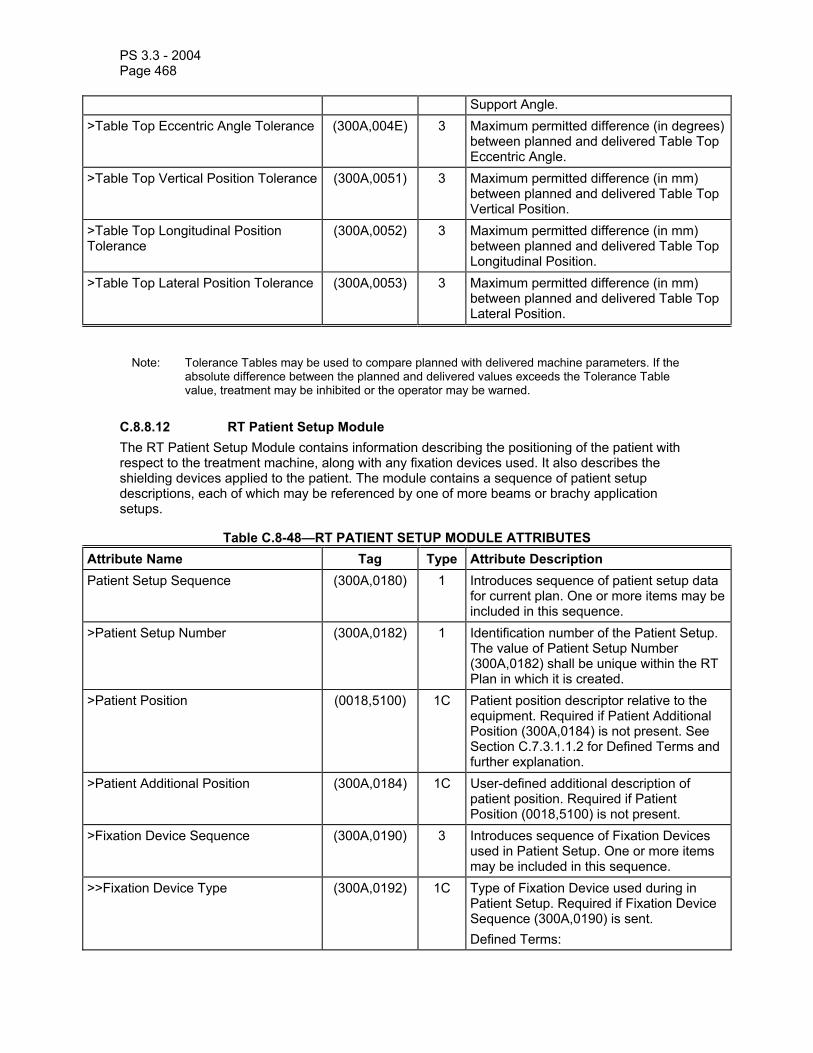
PS 3.3 - 2004 Page 468
Support Angle. >Table Top Eccentric Angle Tolerance (300A,004E) 3 Maximum permitted difference (in degrees)
between planned and delivered Table Top Eccentric Angle.
>Table Top Vertical Position Tolerance (300A,0051) 3 Maximum permitted difference (in mm) between planned and delivered Table Top Vertical Position.
>Table Top Longitudinal Position Tolerance
(300A,0052) 3 Maximum permitted difference (in mm) between planned and delivered Table Top Longitudinal Position.
>Table Top Lateral Position Tolerance (300A,0053) 3 Maximum permitted difference (in mm) between planned and delivered Table Top Lateral Position.
Note: Tolerance Tables may be used to compare planned with delivered machine parameters. If the absolute difference between the planned and delivered values exceeds the Tolerance Table value, treatment may be inhibited or the operator may be warned.
C.8.8.12 RT Patient Setup Module The RT Patient Setup Module contains information describing the positioning of the patient with respect to the treatment machine, along with any fixation devices used. It also describes the shielding devices applied to the patient. The module contains a sequence of patient setup descriptions, each of which may be referenced by one of more beams or brachy application setups.
Table C.8-48—RT PATIENT SETUP MODULE ATTRIBUTES Attribute Name Tag Type Attribute Description Patient Setup Sequence (300A,0180) 1 Introduces sequence of patient setup data
for current plan. One or more items may be included in this sequence.
>Patient Setup Number (300A,0182) 1 Identification number of the Patient Setup. The value of Patient Setup Number (300A,0182) shall be unique within the RT Plan in which it is created.
>Patient Position (0018,5100) 1C Patient position descriptor relative to the equipment. Required if Patient Additional Position (300A,0184) is not present. See Section C.7.3.1.1.2 for Defined Terms and further explanation.
>Patient Additional Position (300A,0184) 1C User-defined additional description of patient position. Required if Patient Position (0018,5100) is not present.
>Fixation Device Sequence (300A,0190) 3 Introduces sequence of Fixation Devices used in Patient Setup. One or more items may be included in this sequence.
>>Fixation Device Type (300A,0192) 1C Type of Fixation Device used during in Patient Setup. Required if Fixation Device Sequence (300A,0190) is sent. Defined Terms:

PS 3.3 - 2004 Page 469
BITEBLOCK HEADFRAME MASK MOLD CAST HEADREST BREAST_BOARD BODY_FRAME VACUUM_MOLD
>>Fixation Device Label (300A,0194) 2C User-defined label identifier for Fixation Device. Required if Fixation Device Sequence (300A,0190) is sent.
>>Fixation Device Description (300A,0196) 3 User-defined description of Fixation Device.
>>Fixation Device Position (300A,0198) 3 Position/Notch number of Fixation Device. >>Accessory Code (300A,00F9) 3 An identifier for the accessory intended to
be read by a device such as a bar-code reader.
>Shielding Device Sequence (300A,01A0) 3 Introduces sequence of Shielding Devices used in Patient Setup. One or more items may be included in this sequence.
>>Shielding Device Type (300A,01A2) 1C Type of Shielding Device used in Patient Setup. Required if Shielding Device Sequence (300A,01A0) is sent. Defined Terms: GUM EYE GONAD
>>Shielding Device Label (300A,01A4) 2C User-defined label for Shielding Device. Required if Shielding Device Sequence (300A,01A0) is sent.
>>Shielding Device Description (300A,01A6) 3 User-defined description of Shielding Device.
>>Shielding Device Position (300A,01A8) 3 Position/Notch number of Shielding Device.>>Accessory Code (300A,00F9) 3 An identifier for the accessory intended to
be read by a device such as a bar-code reader.
>Setup Technique (300A,01B0) 3 Setup Technique used in Patient Setup. Defined Terms: ISOCENTRIC FIXED_SSD TBI BREAST_BRIDGE SKIN_APPOSITION

PS 3.3 - 2004 Page 470
>Setup Technique Description (300A,01B2) 3 User-defined description of Setup Technique.
>Setup Device Sequence (300A,01B4) 3 Introduces sequence of devices used for patient alignment in Patient Setup. One or more items may be included in this sequence.
>>Setup Device Type (300A,01B6) 1C Type of Setup Device used for Patient alignment. Required if Setup Device Sequence (300A,01B4) is sent. Defined Terms: LASER_POINTER DISTANCE_METER TABLE_HEIGHT MECHANICAL_PTR ARC
>>Setup Device Label (300A,01B8) 2C User-defined label for Setup Device used for patient alignment. Required if Setup Device Sequence (300A,01B4) is sent.
>>Setup Device Description (300A,01BA) 3 User-defined description for Setup Device used for patient alignment.
>>Setup Device Parameter (300A,01BC) 2C Setup Parameter for Setup Device in appropriate IEC 61217 coordinate system. Units shall be mm for distances and angles for degrees. Required if Setup Device Sequence (300A,011B4) is sent.
>>Setup Reference Description (300A,01D0) 3 User-defined description of Setup Reference used for patient alignment.
>Table Top Vertical Setup Displacement
(300A,01D2) 3 Vertical Displacement in IEC TABLE TOP coordinate system (in mm) relative to initial Setup Position, i.e. vertical offset between patient positioning performed using setup and treatment position.
>Table Top Longitudinal Setup Displacement
(300A,01D4) 3 Longitudinal Displacement in IEC TABLE TOP coordinate system (in mm) relative to initial Setup Position, i.e. longitudinal offset between patient positioning performed using setup and treatment position.
>Table Top Lateral Setup Displacement
(300A,01D6) 3 Lateral Displacement in IEC TABLE TOP coordinate system (in mm) relative to initial Setup Position, i.e. lateral offset between patient positioning performed using setup and treatment position.
C.8.8.13 RT Fraction Scheme Module The RT Fraction Scheme module contains attributes that describe a single or multiple scheme of dose descriptions. Each sequence item contains dose specification information, fractionation patterns, and either beam or brachytherapy application setup specifications. The design of the

PS 3.3 - 2004 Page 471
RT Fraction Scheme module allows a beam or brachytherapy application setup to be used in multiple fraction schemes.
Table C.8-49—RT FRACTION SCHEME MODULE ATTRIBUTES Attribute Name Tag Type Attribute Description Fraction Group Sequence (300A,0070) 1 Introduces sequence of Fraction Groups in
current Fraction Scheme. One or more items may be included in this sequence.
>Fraction Group Number (300A,0071) 1 Identification number of the Fraction Group. The value of Fraction Group Number (300A,0071) shall be unique within the RT Plan in which it is created.
>Fraction Group Description (300A,0072) 3 The user defined description for the fraction group.
>Referenced Patient Setup Number (300C,006A) 3 Uniquely identifies Patient Setup specified by Patient Setup Number (300A,0182) within Patient Setup Sequence (300A,0180) in RT Patient Setup Module.
>Referenced Dose Sequence (300C,0080) 3 Introduces sequence of related SOP Class/Instance pairs describing related instances of RT Dose (for grids, isodose curves and named/unnamed point doses). One or more items may be included in this sequence. See Note 1.
>>Referenced SOP Class UID (0008,1150) 1C Uniquely identifies the referenced SOP Class. Required if Referenced Dose Sequence (300C,0080) is sent.
>>Referenced SOP Instance UID (0008,1155) 1C Uniquely identifies the referenced SOP Instance. Required if Referenced Dose Sequence (300C,0080) is sent.
>Referenced Dose Reference Sequence
(300C,0050) 3 Introduces sequence of Dose References for the current Fraction Group. One or more items may be included in this sequence.
>>Referenced Dose Reference Number
(300C,0051) 1C Uniquely identifies Dose Reference specified by Dose Reference Number (300A,0012) within Dose Reference Sequence (300A,0010) in RT Prescription Module. Required if Referenced Dose Reference Sequence (300C,0050) is sent.
>>Constraint Weight (300A,0021) 3 Relative importance of satisfying constraint, where high values represent more important constraints.
>>Delivery Warning Dose (300A,0022) 3 The dose (in Gy) which when reached or exceeded should cause some action to be taken.
>>Delivery Maximum Dose (300A,0023) 3 The maximum dose (in Gy) which can be delivered to the dose reference.
>>Target Minimum Dose (300A,0025) 3 Minimum permitted dose (in Gy) to Dose Reference if Dose Reference Type

PS 3.3 - 2004 Page 472
(300A,0020) of referenced Dose Reference is TARGET.
>>Target Prescription Dose (300A,0026) 3 Prescribed dose (in Gy) to Dose Reference if Dose Reference Type (300A,0020) of referenced Dose Reference is TARGET.
>>Target Maximum Dose (300A,0027) 3 Maximum permitted dose (in Gy) to Dose Reference if Dose Reference Type (300A,0020) of referenced Dose Reference is TARGET.
>>Target Underdose Volume Fraction (300A,0028) 3 Maximum permitted fraction (in percent) of Target to receive less than the Target Prescription Dose (300A,0027) if Dose Reference Type (300A,0020) of referenced Dose Reference is TARGET and Dose Reference Structure Type (300A,0014) of referenced Dose Reference is VOLUME.
>>Organ at Risk Full-volume Dose (300A,002A) 3 Maximum dose (in Gy) to entire Dose Reference if Dose Reference Type (300A,0020) of referenced Dose Reference is ORGAN_AT_RISK and Dose Reference Structure Type (300A,0014) of referenced Dose Reference is VOLUME.
>>Organ at Risk Limit Dose (300A,002B) 3 Maximum permitted dose (in Gy) to any part of Dose Reference if Dose Reference Type (300A,0020) of referenced Dose Reference is ORGAN_AT_RISK and Dose Reference Structure Type (300A,0014) of referenced Dose Reference is VOLUME.
>>Organ at Risk Maximum Dose (300A,002C) 3 Maximum dose (in Gy) to non-overdosed part of Dose Reference if Dose Reference Type (300A,0020) of referenced Dose Reference is ORGAN_AT_RISK and Dose Reference Structure Type (300A,0014) of referenced Dose Reference is VOLUME.
>>Organ at Risk Overdose Volume Fraction
(300A,002D) 3 Maximum permitted fraction (in percent) of Organ at Risk to receive more than the Organ at Risk Maximum Dose if Dose Reference Type (300A,0020) of referenced Dose Reference is ORGAN_AT_RISK and Dose Reference Structure Type (300A,0014) of referenced Dose Reference is VOLUME.
>Number of Fractions Planned (300A,0078) 2 Total number of treatments (Fractions) prescribed for current Fraction Group.
>Number of Fraction Pattern Digits Per Day
(300A,0079) 3 Number of digits in Fraction Pattern (300A,007B) used to represent one day. See Note 2.
>Repeat Fraction Cycle Length (300A,007A) 3 Number of weeks needed to describe treatment pattern. See Note 2.
>Fraction Pattern (300A,007B) 3 String of 0's (no treatment) and 1's (treatment) describing treatment pattern.

PS 3.3 - 2004 Page 473
Length of string is 7 x Number of Fraction Pattern Digits Per Day x Repeat Fraction Cycle Length. Pattern shall start on a Monday. See Note 2.
>Number of Beams (300A,0080) 1 Number of Beams in current Fraction Group. If Number of Beams is greater then zero, Number of Brachy Application Setups (300A,00A0) shall equal zero.
>Referenced Beam Sequence (300C,0004) 1C Introduces sequence of treatment beams in current Fraction Group. Required if Number of Beams (300A,0080) is greater than zero. One or more items may be included in this sequence.
>>Referenced Beam Number (300C,0006) 1C Uniquely identifies Beam specified by Beam Number (300A,00C0) within Beam Sequence (300A,00B0) in RT Beams Module. Required if Referenced Beam Sequence (300C,0004) is sent.
>>Beam Dose Specification Point (300A,0082) 3 Coordinates (x,y,z) of point at which Beam Dose is specified in the patient based coordinate system described in C.7.6.2.1.1 (mm). See Note 3.
>>Beam Dose (300A,0084) 3 Dose (in Gy) at Beam Dose Specification Point (300A,0082) due to current Beam.
>>Beam Meterset (300A,0086) 3 Machine setting to be delivered for current Beam, specified in Monitor Units (MU) or minutes as defined by Primary Dosimeter Unit (300A,00B3) (in RT Beams Module) for referenced Beam. See Note 4.
>Number of Brachy Application Setups (300A,00A0) 1 Number of Brachy Application Setups in current Fraction Group. If Number of Brachy Application Setups is greater then zero, Number of Beams (300A,0080) shall equal zero.
>Referenced Brachy Application Setup Sequence
(300C,000A) 1C Introduces sequence of treatment Brachy Application Setups in current Fraction Group. Required if Number of Brachy Application Setups (300A,00A0) is greater than zero. One or more items may be included in this sequence.
>>Referenced Brachy Application Setup Number
(300C,000C) 1C Uniquely identifies Brachy Application Setup specified by Brachy Application Setup Number (300A,0234) within Brachy Application Setup Sequence (300A,0230) in RT Brachy Application Setups Module. Required if Referenced Brachy Application Setup Sequence (300C,000A) is sent.
>>Brachy Application Setup Dose Specification Point
(300A,00A2) 3 Coordinates (x,y,z) of point in the patient based coordinate system described in C.7.6.2.1.1 at which Brachy Application Setup Dose (300A,00A4) is specified (mm).

PS 3.3 - 2004 Page 474
>>Brachy Application Setup Dose (300A,00A4) 3 Dose (in Gy) at Brachy Application Setup Dose Specification Point (300A,00A2) due to current Brachy Application Setup.
Notes: 1. An RT Dose IOD referenced within the Referenced Dose Sequence (300C,0080) can be used for storing grid-based (pixel) data, isodose curves, and/or individual dose points (with optional dose point names) for the current Fraction Group.
2. The fractionation pattern does not indicate the actual start of treatment, or the order or timing of fraction delivery. If treatment does not commence as outlined in the pattern, it is the application’s responsibility to make any necessary adjustments.
Examples of Fractionation Pattern Schemes: a) 1 fraction group, 1 fraction per day (Monday to Friday): Number of Fraction Pattern Digits per Day = 1, Repeat Fraction Cycle Length = 1, Fraction
Pattern = 1111100 b) 2 fraction groups, 1 fraction per day, first fraction group Monday, Wednesday, and Friday,
second fraction group Tuesday and Thursday: Fraction Group 1: Number of Fraction Pattern Digits Per Day = 1, Repeat Fraction Cycle Length
= 1, Fraction Pattern = 1010100 Fraction Group 2: Number of Fraction Pattern Digits Per Day = 1, Repeat Fraction Cycle Length
= 1, Fraction Pattern = 0101000 c) 2 fraction groups, 1 fraction per day, alternating fraction groups every day of treatment
(Monday to Friday): Fraction Group 1: Number of Fraction Pattern Digits Per Day = 1, Repeat Fraction Cycle Length
= 2, Fraction Pattern = 10101000101000 Fraction Group 2: Number of Fraction Pattern Digits Per Day = 1, Repeat Fraction Cycle Length
= 2, Fraction Pattern = 01010001010100 d) 1 fraction group, 2 fractions per day (Monday to Friday): Fraction Group 1: Number of Fraction Pattern Digits Per Day = 2, Repeat Fraction Cycle Length
= 1, Fraction Pattern = 11111111110000 e) 2 fraction groups, 2 fractions per day, alternating fraction groups every treatment (Monday to
Friday): Fraction Group 1: Number of Fraction Pattern Digits Per Day = 1, Repeat Fraction Cycle Length
= 1, Fraction Pattern = 1111100 Fraction Group 2: Number of Fraction Pattern Digits Per Day = 2, Repeat Fraction Cycle Length
= 1, Fraction Pattern = 11111111110000 3. The Beam Dose Specification Point (300A,0082) and Brachy Application Setup Dose
Specification Point (300A,00A2) contain the coordinates of the single point used for dose normalization. This point is distinct from the Referenced Dose Reference Sequence (300C,0050) in the RT Beams module and the Brachy Referenced Dose Reference Sequence (300A,0055) in the RT Brachy Application Setups module, which are used for plan evaluation and dose tracking.
4. The Meterset at a given Control Point (see RT Beams Module) is equal to the Beam Meterset (300A,0086) multiplied by the Cumulative Meterset Weight (300A,0134) for the Control Point, divided by the Final Cumulative Meterset Weight (300A,010E).

PS 3.3 - 2004 Page 475
C.8.8.14 RT Beams Module The RT Beams Module contains information defining equipment parameters for delivery of external radiation beams.
Table C.8-50—RT BEAMS MODULE ATTRIBUTES Attribute Name Tag Type Attribute Description Beam Sequence (300A,00B0) 1 Introduces sequence of treatment beams
for current RT Plan. One or more items may be included in this sequence.
>Beam Number (300A,00C0) 1 Identification number of the Beam. The value of Beam Number (300A,00C0) shall be unique within the RT Plan in which it is created. See Note 1.
>Beam Name (300A,00C2) 3 User-defined name for Beam. See Note 1. >Beam Description (300A,00C3) 3 User-defined description for Beam. See
Note 1. >Beam Type (300A,00C4) 1 Motion characteristic of Beam. See Note 5.
Enumerated Values: STATIC = All Control Point Sequence (300A,0111) attributes remain unchanged between consecutive pairs of control points with changing Cumulative Meterset Weight (300A,0134). DYNAMIC = One or more Control Point Sequence (300A,0111) attributes change between one or more consecutive pairs of control points with changing Cumulative Meterset Weight (300A,0134).
>Radiation Type (300A,00C6) 2 Particle type of Beam. Defined Terms: PHOTON ELECTRON NEUTRON PROTON
>High-Dose Technique Type (300A,00C7) 1C Type of high-dose treatment technique. Defined Terms: NORMAL = Standard treatment TBI = Total Body Irradiation HDR = High Dose Rate Required if treatment technique requires a dose that would normally require overriding of treatment machine safety controls.
>Treatment Machine Name (300A,00B2) 2 User-defined name identifying treatment machine to be used for beam delivery. See Note 2.
>Manufacturer (0008,0070) 3 Manufacturer of the equipment to be used for beam delivery.

PS 3.3 - 2004 Page 476
>Institution Name (0008,0080) 3 Institution where the equipment is located that is to be used for beam delivery.
>Institution Address (0008,0081) 3 Mailing address of the institution where the equipment is located that is to be used for beam delivery.
>Institutional Department Name (0008,1040) 3 Department in the institution where the equipment is located that is to be used for beam delivery.
>Manufacturer's Model Name (0008,1090) 3 Manufacturer's model name of the equipment that is to be used for beam delivery.
>Device Serial Number (0018,1000) 3 Manufacturer's serial number of the equipment that is to be used for beam delivery.
>Primary Dosimeter Unit (300A,00B3) 3 Measurement unit of machine dosimeter. See C.8.8.14.1. Enumerated Values: MU = Monitor Unit MINUTE = minute
>Referenced Tolerance Table Number (300C,00A0) 3 Uniquely identifies Tolerance Table specified by Tolerance Table Number (300A,0042) within Tolerance Table Sequence in RT Tolerance Tables Module. These tolerances are to be used for verification of treatment machine settings.
>Source-Axis Distance (300A,00B4) 3 Radiation source to Gantry rotation axis distance of the equipment that is to be used for beam delivery (mm).
>Beam Limiting Device Sequence (300A,00B6) 1 Introduces sequence of beam limiting device (collimator) jaw or leaf (element) sets. One or more items may be included in this sequence.
>>RT Beam Limiting Device Type (300A,00B8) 1 Type of beam limiting device (collimator). Enumerated Values: X = symmetric jaw pair in IEC X direction Y = symmetric jaw pair in IEC Y direction ASYMX = asymmetric jaw pair in IEC X direction ASYMY = asymmetric pair in IEC Y direction MLCX = multileaf (multi-element) jaw pair in IEC X direction MLCY = multileaf (multi-element) jaw pair in IEC Y direction
>>Source to Beam Limiting Device Distance
(300A,00BA) 3 Radiation source to beam limiting device (collimator) distance of the equipment that is to be used for beam delivery (mm).

PS 3.3 - 2004 Page 477
>>Number of Leaf/Jaw Pairs (300A,00BC) 1 Number of leaf (element) or jaw pairs (equal to 1 for standard beam limiting device jaws).
>>Leaf Position Boundaries (300A,00BE) 2C Boundaries of beam limiting device (collimator) leaves (in mm) in IEC BEAM LIMITING DEVICE coordinate axis appropriate to RT Beam Limiting Device Type (300A,00B8), i.e. X-axis for MLCY, Y-axis for MLCX. Contains N+1 values, where N is the Number of Leaf/Jaw Pairs (300A,00BC), starting from Leaf (Element) Pair 1. Required if Beam Limiting Device Sequence (300A,00B6) is sent and RT Beam Limiting Device Type (300A,00B8) is MLCX or MLCY. See Note 3.
>Referenced Patient Setup Number (300C,006A) 3 Uniquely identifies Patient Setup to be used for current beam, specified by Patient Setup Number (300A,0182) within Patient Setup Sequence of RT Patient Setup Module.
>Referenced Reference Image Sequence
(300C,0042) 3 Introduces sequence of reference images used for validation of current beam. One or more items may be included in this sequence.
>>Referenced SOP Class UID (0008,1150) 1C Uniquely identifies the referenced SOP Class. Required if Referenced Reference Image Sequence (300C,0042) is sent.
>>Referenced SOP Instance UID (0008,1155) 1C Uniquely identifies the referenced SOP Instance. Required if Referenced Reference Image Sequence (300C,0042) is sent.
>>Reference Image Number (300A,00C8) 1C Uniquely identifies Reference Image within Referenced Reference Image Sequence (300A,0042). Required if Referenced Reference Image Sequence (300A,0042) is sent.
>>Start Cumulative Meterset Weight (300C,0008) 3 Cumulative Meterset Weight within current Beam at which image acquisition starts.
>>End Cumulative Meterset Weight (300C,0009) 3 Cumulative Meterset Weight within current Beam at which image acquisition ends.
>Planned Verification Image Sequence (300A,00CA) 3 Introduces sequence of planned verification images to be acquired during current beam. One or more items may be included in this sequence. See C.8.8.14.2.
>>Start Cumulative Meterset Weight (300C,0008) 3 Cumulative Meterset Weight within current Beam at which image acquisition will start.
>>Meterset Exposure (3002,0032) 3 Meterset duration over which image is to be acquired, specified in Monitor units (MU) or minutes as defined by Primary Dosimeter Unit (300A,00B3).

PS 3.3 - 2004 Page 478
>>End Cumulative Meterset Weight (300C,0009) 3 Cumulative Meterset Weight within current Beam at which image acquisition will end.
>>RT Image Plane (3002,000C) 3 Describes whether or not image plane is normal to beam axis. Enumerated Values: NORMAL = image plane normal to beam axis NON_NORMAL = image plane non-normal to beam axis
>>X-Ray Image Receptor Angle (3002,000E) 3 X-Ray Image Receptor Angle i.e. orientation of IEC X-RAY IMAGE RECEPTOR coordinate system with respect to IEC GANTRY coordinate system (degrees). See C.8.8.14.3.
>>RT Image Orientation (3002,0010) 3 The direction cosines of the first row and the first column with respect to the IEC X-RAY IMAGE RECEPTOR coordinate system.
>>RT Image Position (3002,0012) 3 The x and y coordinates (in mm) of the upper left hand corner of the image, in the IEC X-RAY IMAGE RECEPTOR coordinate system. This is the center of the first pixel transmitted.
>>RT Image SID (3002,0026) 3 Radiation machine source to image plane distance (mm).
>>Imaging Device-Specific Acquisition Parameters
(300A,00CC) 3 User-specified device-specific parameters that describe how the imager will acquire the image.
>>Referenced Reference Image Number
(300C,0007) 3 Uniquely identifies Reference Image to which planned verification image is related, specified by Reference Image Number (300A,00C8) within Referenced Reference Image Sequence (300A,0042).
>Treatment Delivery Type (300A,00CE) 3 Delivery Type of treatment. Defined Terms: TREATMENT = normal patient treatment OPEN_PORTFILM = portal image acquisition with open field TRMT_PORTFILM = portal image acquisition with treatment port CONTINUATION = continuation of interrupted treatment
>Referenced Dose Sequence (300C,0080) 3 Introduces sequence of related SOP Class/Instance pairs describing related instances of RT Dose (for grids, isodose curves, and named/unnamed point doses). One or more items may be included in this sequence.
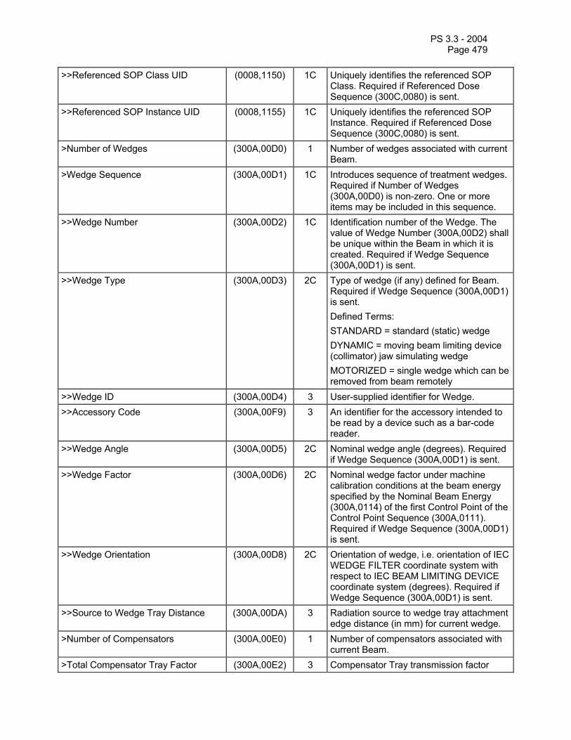
PS 3.3 - 2004 Page 479
>>Referenced SOP Class UID (0008,1150) 1C Uniquely identifies the referenced SOP Class. Required if Referenced Dose Sequence (300C,0080) is sent.
>>Referenced SOP Instance UID (0008,1155) 1C Uniquely identifies the referenced SOP Instance. Required if Referenced Dose Sequence (300C,0080) is sent.
>Number of Wedges (300A,00D0) 1 Number of wedges associated with current Beam.
>Wedge Sequence (300A,00D1) 1C Introduces sequence of treatment wedges. Required if Number of Wedges (300A,00D0) is non-zero. One or more items may be included in this sequence.
>>Wedge Number (300A,00D2) 1C Identification number of the Wedge. The value of Wedge Number (300A,00D2) shall be unique within the Beam in which it is created. Required if Wedge Sequence (300A,00D1) is sent.
>>Wedge Type (300A,00D3) 2C Type of wedge (if any) defined for Beam. Required if Wedge Sequence (300A,00D1) is sent. Defined Terms: STANDARD = standard (static) wedge DYNAMIC = moving beam limiting device (collimator) jaw simulating wedge MOTORIZED = single wedge which can be removed from beam remotely
>>Wedge ID (300A,00D4) 3 User-supplied identifier for Wedge. >>Accessory Code (300A,00F9) 3 An identifier for the accessory intended to
be read by a device such as a bar-code reader.
>>Wedge Angle (300A,00D5) 2C Nominal wedge angle (degrees). Required if Wedge Sequence (300A,00D1) is sent.
>>Wedge Factor (300A,00D6) 2C Nominal wedge factor under machine calibration conditions at the beam energy specified by the Nominal Beam Energy (300A,0114) of the first Control Point of the Control Point Sequence (300A,0111). Required if Wedge Sequence (300A,00D1) is sent.
>>Wedge Orientation (300A,00D8) 2C Orientation of wedge, i.e. orientation of IEC WEDGE FILTER coordinate system with respect to IEC BEAM LIMITING DEVICE coordinate system (degrees). Required if Wedge Sequence (300A,00D1) is sent.
>>Source to Wedge Tray Distance (300A,00DA) 3 Radiation source to wedge tray attachment edge distance (in mm) for current wedge.
>Number of Compensators (300A,00E0) 1 Number of compensators associated with current Beam.
>Total Compensator Tray Factor (300A,00E2) 3 Compensator Tray transmission factor

PS 3.3 - 2004 Page 480
(between 0 and 1), at the beam energy specified by the Nominal Beam Energy (300A,0114) of the first Control Point of the Control Point Sequence (300A,0111).
>Compensator Sequence (300A,00E3) 1C Introduces sequence of treatment compensators. Required if Number of Compensators (300A,00E0) is non-zero. One or more items may be included in this sequence.
>>Compensator Number (300A,00E4) 1C Identification number of the Compensator. The value of Compensator Number (300A,00E4) shall be unique within the Beam in which it is created. Required if Number of Compensators (300A,00E0) is non-zero.
>>Compensator Type (3004,00EE) 3 Type of compensator (if any). Defined Terms: STANDARD = physical (static) compensator DYNAMIC = moving Beam Limiting Device (collimator) simulating physical compensator
>>Material ID (300A,00E1) 2C User-supplied identifier for material used to manufacture Compensator. Required if Number of Compensators (300A,00E0) is non-zero.
>>Compensator ID (300A,00E5) 3 User-supplied identifier for compensator. >>Accessory Code (300A,00F9) 3 An identifier for the accessory intended to
be read by a device such as a bar-code reader.
>>Source to Compensator Tray Distance
(300A,00E6) 2C Radiation source to compensator tray attachment edge distance (in mm) for current compensator. Required if Compensator Sequence (300A,00E3) is sent.
>>Compensator Divergence (300A,02E0) 3 Indicates presence or absence of geometrical divergence of the compensator. Enumerated Values: PRESENT = the compensator is shaped according to the beam geometrical divergence. ABSENT = the compensator is not shaped according to the beam geometrical divergence.
>>Compensator Mounting Position (300A,02E1) 3 Indicates on which side of the Compensator Tray the compensator is mounted. Enumerated Values: PATIENT_SIDE = the compensator is mounted on the side of the Compensator Tray which is towards the patient.

PS 3.3 - 2004 Page 481
SOURCE_SIDE = the compensator is mounted on the side of the Compensator Tray which is towards the radiation source.DOUBLE_SIDED = the compensator has a shaped (i.e. non-flat) surface on both sides of the Compensator Tray.
>>Compensator Rows (300A,00E7) 1C Number of rows in the compensator. Required if Compensator Sequence (300A,00E3) is sent.
>>Compensator Columns (300A,00E8) 1C Number of columns in the compensator. Required if Compensator Sequence (300A,00E3) is sent.
>>Compensator Pixel Spacing (300A,00E9) 1C Physical distance (in mm) between the center of each pixel projected onto machine isocentric plane. Specified by a numeric pair - adjacent row spacing (delimiter) adjacent column spacing. Required if Compensator Sequence (300A,00E3) is sent.
>>Compensator Position (300A,00EA) 1C The x and y coordinates of the upper left hand corner (first pixel transmitted) of the compensator, projected onto the machine isocentric plane in the IEC BEAM LIMITING DEVICE coordinate system (mm). Required if Compensator Sequence (300A,00E3) is sent.
>>Compensator Transmission Data (300A,00EB) 1C A data stream of the pixel samples which comprise the compensator, expressed as broad-beam transmission values (between 0 and 1) along a ray line passing through the pixel, at the beam energy specified by the Nominal Beam Energy (300A,0114) of the first Control Point of the Control Point Sequence (300A,0111). The order of pixels sent is left to right, top to bottom, i.e., the upper left pixel is sent first followed by the remainder of the first row , followed by the first pixel of the 2nd row, then the remainder of the 2nd row and so on) when viewed from the radiation source. Required if Compensator Sequence (300A,00E3) is sent and Material ID (300A,00E1) is zero-length.
>>Compensator Thickness Data (300A,00EC) 1C A data stream of the pixel samples which comprise the compensator, expressed as thicknesses (in mm). The order of pixels sent is left to right, top to bottom, i.e., the upper left pixel is sent first followed by the remainder of the first row , followed by the first pixel of the 2nd row, then the remainder of the 2nd row and so on) when viewed from the radiation source. Required if Compensator Sequence (300A,00E3) is
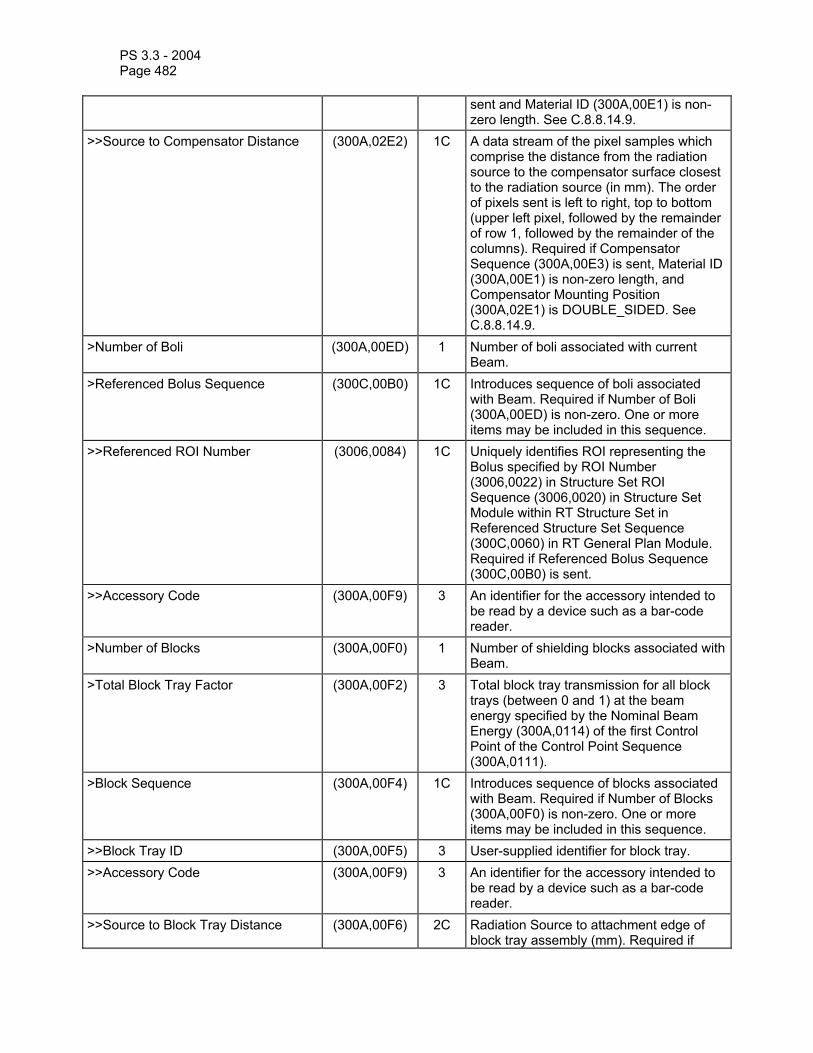
PS 3.3 - 2004 Page 482
sent and Material ID (300A,00E1) is non-zero length. See C.8.8.14.9.
>>Source to Compensator Distance (300A,02E2) 1C A data stream of the pixel samples which comprise the distance from the radiation source to the compensator surface closest to the radiation source (in mm). The order of pixels sent is left to right, top to bottom (upper left pixel, followed by the remainder of row 1, followed by the remainder of the columns). Required if Compensator Sequence (300A,00E3) is sent, Material ID (300A,00E1) is non-zero length, and Compensator Mounting Position (300A,02E1) is DOUBLE_SIDED. See C.8.8.14.9.
>Number of Boli (300A,00ED) 1 Number of boli associated with current Beam.
>Referenced Bolus Sequence (300C,00B0) 1C Introduces sequence of boli associated with Beam. Required if Number of Boli (300A,00ED) is non-zero. One or more items may be included in this sequence.
>>Referenced ROI Number (3006,0084) 1C Uniquely identifies ROI representing the Bolus specified by ROI Number (3006,0022) in Structure Set ROI Sequence (3006,0020) in Structure Set Module within RT Structure Set in Referenced Structure Set Sequence (300C,0060) in RT General Plan Module. Required if Referenced Bolus Sequence (300C,00B0) is sent.
>>Accessory Code (300A,00F9) 3 An identifier for the accessory intended to be read by a device such as a bar-code reader.
>Number of Blocks (300A,00F0) 1 Number of shielding blocks associated with Beam.
>Total Block Tray Factor (300A,00F2) 3 Total block tray transmission for all block trays (between 0 and 1) at the beam energy specified by the Nominal Beam Energy (300A,0114) of the first Control Point of the Control Point Sequence (300A,0111).
>Block Sequence (300A,00F4) 1C Introduces sequence of blocks associated with Beam. Required if Number of Blocks (300A,00F0) is non-zero. One or more items may be included in this sequence.
>>Block Tray ID (300A,00F5) 3 User-supplied identifier for block tray. >>Accessory Code (300A,00F9) 3 An identifier for the accessory intended to
be read by a device such as a bar-code reader.
>>Source to Block Tray Distance (300A,00F6) 2C Radiation Source to attachment edge of block tray assembly (mm). Required if
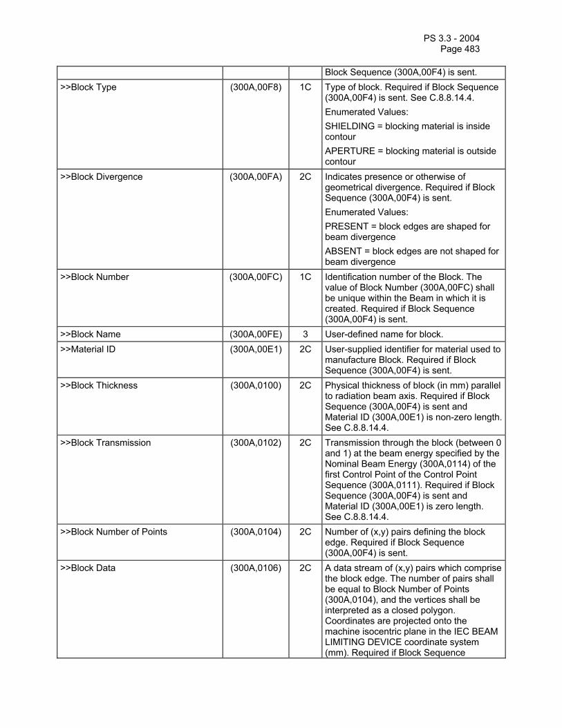
PS 3.3 - 2004 Page 483
Block Sequence (300A,00F4) is sent. >>Block Type (300A,00F8) 1C Type of block. Required if Block Sequence
(300A,00F4) is sent. See C.8.8.14.4. Enumerated Values: SHIELDING = blocking material is inside contour APERTURE = blocking material is outside contour
>>Block Divergence (300A,00FA) 2C Indicates presence or otherwise of geometrical divergence. Required if Block Sequence (300A,00F4) is sent. Enumerated Values: PRESENT = block edges are shaped for beam divergence ABSENT = block edges are not shaped for beam divergence
>>Block Number (300A,00FC) 1C Identification number of the Block. The value of Block Number (300A,00FC) shall be unique within the Beam in which it is created. Required if Block Sequence (300A,00F4) is sent.
>>Block Name (300A,00FE) 3 User-defined name for block. >>Material ID (300A,00E1) 2C User-supplied identifier for material used to
manufacture Block. Required if Block Sequence (300A,00F4) is sent.
>>Block Thickness (300A,0100) 2C Physical thickness of block (in mm) parallel to radiation beam axis. Required if Block Sequence (300A,00F4) is sent and Material ID (300A,00E1) is non-zero length. See C.8.8.14.4.
>>Block Transmission (300A,0102) 2C Transmission through the block (between 0 and 1) at the beam energy specified by the Nominal Beam Energy (300A,0114) of the first Control Point of the Control Point Sequence (300A,0111). Required if Block Sequence (300A,00F4) is sent and Material ID (300A,00E1) is zero length. See C.8.8.14.4.
>>Block Number of Points (300A,0104) 2C Number of (x,y) pairs defining the block edge. Required if Block Sequence (300A,00F4) is sent.
>>Block Data (300A,0106) 2C A data stream of (x,y) pairs which comprise the block edge. The number of pairs shall be equal to Block Number of Points (300A,0104), and the vertices shall be interpreted as a closed polygon. Coordinates are projected onto the machine isocentric plane in the IEC BEAM LIMITING DEVICE coordinate system (mm). Required if Block Sequence

PS 3.3 - 2004 Page 484
(300A,00F4) is sent. See Note 4. >Applicator Sequence (300A,0107) 3 Introduces sequence of Applicators
associated with Beam. Only a single item shall be permitted in this sequence.
>>Applicator ID (300A,0108) 1C User or machine supplied identifier for Applicator. Required if Applicator Sequence (300A,0107) is sent.
>>Accessory Code (300A,00F9) 3 An identifier for the accessory intended to be read by a device such as a bar-code reader.
>>Applicator Type (300A,0109) 1C Type of Applicator. Required if Applicator Sequence (300A,0107) is sent. Defined Terms: ELECTRON_SQUARE = square electron applicator ELECTRON_RECT = rectangular electron applicator ELECTRON_CIRC = circular electron applicator ELECTRON_SHORT = short electron applicator ELECTRON_OPEN = open (dummy) electron applicator INTRAOPERATIVE = intraoperative (custom) applicator STEREOTACTIC = stereotactic applicator
>>Applicator Description (300A,010A) 3 User-defined description for Applicator. >Final Cumulative Meterset Weight (300A,010E) 1C Value of Cumulative Meterset Weight
(300A,0134) for final Control Point in Control Point Sequence (300A,0111). Required if Cumulative Meterset Weight is non-null in Control Points specified within Control Point Sequence (300A,0111). See C.8.8.14.1.
>Number of Control Points (300A,0110) 1 Number of control points in Beam. >Control Point Sequence (300A,0111) 1 Introduces sequence of machine
configurations describing treatment beam. Two or more items may be included in this sequence. See C.8.8.14.5 and C.8.8.14.6.
>>Control Point Index (300A,0112) 1C Index of current Control Point, starting at 0 for first Control Point. Required if Control Point Sequence (300A, 0111) is sent.
>>Cumulative Meterset Weight (300A,0134) 2C Cumulative weight to current control point. Cumulative Meterset Weight for the first item in Control Point Sequence shall always be zero. Cumulative Meterset Weight for the final item in Control Point Sequence shall always be equal to Final Cumulative Meterset Weight. Required if

PS 3.3 - 2004 Page 485
Control Point Sequence (300A,0111) is sent. See C.8.8.14.1.
>>Referenced Dose Reference Sequence
(300C,0050) 3 Introduces a sequence of Dose References for current Beam. One or more items may be included in this sequence.
>>>Referenced Dose Reference Number
(300C,0051) 1C Uniquely identifies Dose Reference specified by Dose Reference Number (300A,0012) in Dose Reference Sequence (300A,0010) in RT Prescription Module. Required if Referenced Dose Reference Sequence (300C,0050) is sent.
>>>Cumulative Dose Reference Coefficient
(300A,010C) 2C Coefficient used to calculate cumulative dose contribution from this Beam to the referenced Dose Reference at the current Control Point. Required if Referenced Dose Reference Sequence (300C,0050) is sent. See C.8.8.14.7.
>>Nominal Beam Energy (300A,0114) 3 Nominal Beam Energy at control point (MV/MeV).
>>Dose Rate Set (300A,0115) 3 Dose Rate to be set on treatment machine for segment beginning at current control point (e.g. MU/min).
>>Wedge Position Sequence (300A,0116) 3 A Sequence of Items describing Wedge Positions for the current control point. Required for first item of Control Point Sequence if Number of Wedges (300A,00D0) is non-zero, and in subsequent control points if Wedge Position (300A,0118) changes during Beam. See C.8.8.14.5. The number of items in this sequence shall equal the value of Number of Wedges (300A,00D0).
>>>Referenced Wedge Number (300C,00C0) 1C Uniquely references Wedge described by Wedge Number (300A,00D2) in Wedge Sequence (300A,00D1). Required if Wedge Position Sequence (300A,0116) is sent.
>>>Wedge Position (300A,0118) 1C Position of Wedge at current Control Point. Required if Wedge Position Sequence (300A,0116) is sent. Enumerated Values: IN OUT
>>Beam Limiting Device Position Sequence
(300A,011A) 1C Introduces sequence of beam limiting device (collimator) jaw or leaf (element) positions. Required for first item of Control Point Sequence, or if Beam Limiting Device changes during Beam. One or more items may be included in this sequence.

PS 3.3 - 2004 Page 486
>>>RT Beam Limiting Device Type (300A,00B8) 1C Type of beam limiting device (collimator). The value of this attribute shall correspond to RT Beam Limiting Device Type (300A,00B8) defined in an item of Beam Limiting Device Sequence (300A,00B6). Required if Beam Limiting Device Position Sequence (300A,011A) is sent. Enumerated Values: X = symmetric jaw pair in IEC X direction Y = symmetric jaw pair in IEC Y direction ASYMX = asymmetric jaw pair in IEC X direction ASYMY = asymmetric pair in IEC Y direction MLCX = multileaf (multi-element) jaw pair in IEC X direction MLCY = multileaf (multi-element) jaw pair in IEC Y direction
>>>Leaf/Jaw Positions (300A,011C) 1C Positions of beam limiting device (collimator) leaf (element) or jaw pairs (in mm) in IEC BEAM LIMITING DEVICE coordinate axis appropriate to RT Beam Limiting Device Type (300A,00B8), e.g. X-axis for MLCX, Y-axis for MLCY. Contains 2N values, where N is the Number of Leaf/Jaw Pairs (300A,00BC) in Beam Limiting Device Sequence (300A,00B6). Values shall be listed in IEC leaf (element) subscript order 101, 102, ... 1N, 201, 202, ... 2N. Required if Beam Limiting Device Position Sequence (300A,011A) is sent. See Note 2.
>>Gantry Angle (300A,011E) 1C Gantry angle of radiation source, i.e. orientation of IEC GANTRY coordinate system with respect to IEC FIXED REFERENCE coordinate system (degrees). Required for first item of Control Point Sequence, or if Gantry Angle changes during Beam.
>>Gantry Rotation Direction (300A,011F) 1C Direction of Gantry Rotation when viewing gantry from isocenter, for segment following Control Point. Required for first item of Control Point Sequence, or if Gantry Rotation Direction changes during Beam. See C.8.8.14.8. Enumerated Values: CW = clockwise CC = counter-clockwise NONE = no rotation
>>Beam Limiting Device Angle (300A,0120) 1C Beam Limiting Device angle, i.e. orientation

PS 3.3 - 2004 Page 487
of IEC BEAM LIMITING DEVICE coordinate system with respect to IEC GANTRY coordinate system (degrees). Required for first item of Control Point Sequence, or if Beam Limiting Device Angle changes during Beam.
>>Beam Limiting Device Rotation Direction
(300A,0121) 1C Direction of Beam Limiting Device Rotation when viewing beam limiting device (collimator) from radiation source, for segment following Control Point. Required for first item of Control Point Sequence, or if Beam Limiting Device Rotation Direction changes during Beam. See C.8.8.14.8. Enumerated Values: CW = clockwise CC = counter-clockwise NONE = no rotation
>>Patient Support Angle (300A,0122) 1C Patient Support angle, i.e. orientation of IEC PATIENT SUPPORT (turntable) coordinate system with respect to IEC FIXED REFERENCE coordinate system (degrees). Required for first item of Control Point Sequence, or if Patient Support Angle changes during Beam.
>>Patient Support Rotation Direction (300A,0123) 1C Direction of Patient Support Rotation when viewing table from above, for segment following Control Point. Required for first item of Control Point Sequence, or if Patient Support Rotation Direction changes during Beam. See C.8.8.14.8. Enumerated Values: CW = clockwise CC = counter-clockwise NONE = no rotation
>>Table Top Eccentric Axis Distance (300A,0124) 3 Distance (positive) from the IEC PATIENT SUPPORT vertical axis to the IEC TABLE TOP ECCENTRIC vertical axis (mm).
>>Table Top Eccentric Angle (300A,0125) 1C Table Top (non-isocentric) angle, i.e. orientation of IEC TABLE TOP ECCENTRIC coordinate system with respect to IEC PATIENT SUPPORT coordinate system (degrees). Required for first item of Control Point Sequence, or if Table Top Eccentric Angle changes during Beam.
>>Table Top Eccentric Rotation Direction
(300A,0126) 1C Direction of Table Top Eccentric Rotation when viewing table from above, for segment following Control Point. Required for first item of Control Point Sequence, or if Table Top Eccentric Rotation Direction

PS 3.3 - 2004 Page 488
changes during Beam. See C.8.8.14.8. Enumerated Values: CW = clockwise CC = counter-clockwise NONE = no rotation
>>Table Top Vertical Position (300A,0128) 2C Table Top Vertical position in IEC TABLE TOP coordinate system (mm). Required for first item of Control Point Sequence, or if Table Top Vertical Position changes during Beam. See C.8.8.14.6.
>>Table Top Longitudinal Position (300A,0129) 2C Table Top Longitudinal position in IEC TABLE TOP coordinate system (mm). Required for first item of Control Point Sequence, or if Table Top Longitudinal Position changes during Beam. See C.8.8.14.6.
>>Table Top Lateral Position (300A,012A) 2C Table Top Lateral position in IEC TABLE TOP coordinate system (mm). Required for first item of Control Point Sequence, or if Table Top Lateral Position changes during Beam. See C.8.8.14.6.
>>Isocenter Position (300A,012C) 2C Isocenter coordinates (x,y,z) in the patient based coordinate system described in C.7.6.2.1.1 (mm). Required for first item of Segment Control Point Sequence, or if Segment Isocenter Position changes during Beam.
>>Surface Entry Point (300A,012E) 3 Patient surface entry point coordinates (x,y,z) in the patient based coordinate system described in C.7.6.2.1.1 (mm).
>>Source to Surface Distance (300A,0130) 3 Source to Patient Surface distance (mm).
Notes: 1. Beam Number (300A,00C0) is provided to link related information across modules, and its value should not be required to have any real-world interpretation. Beam Name (300A, 00C2), a Type 3 attribute, is intended to store the primary beam identifier (often referred to as “field identifier”). Beam Description (300A,00C3), a Type 3 attribute, is intended to store additional beam identifying information (often referred to as “field name”). Equipment supporting both these attributes should state this clearly in the Conformance Statement.
2. The DICOM standard does not support the transmission of treatment unit modeling information such as depth doses and beam profiles.
3. Implementors should take note that Leaf Position Boundaries (300A,00BE) are the positions of the mechanical boundaries (projected to the isocentric plane) between beam limiting device (collimator) leaves, fixed for a given beam limiting device (collimator). Leaf/Jaw Positions (300A,011C) are values specific to a given beam control point, specifying the beam limiting device (collimator) leaf (element) openings.
4. Block coordinates may not be transmitted when such data is not available from the transmitting system. However, the receiving system may not have internal mechanisms to use or store such data. For example, a plan sent from an treatment planning system to a Record and Verify (R&V) system will contain the block data for blocked beams. Subsequent transfer of beam data from the R&V system may omit this data since the R&V system may not have stored it.

PS 3.3 - 2004 Page 489
5. Refer to C.8.8.14.5 for examples of STATIC and DYNAMIC Beam Type. Note that beams having Wedge Type = DYNAMIC as the only moving parameter are not considered DYNAMIC according to the definition of Beam Type (300A,00C4).
C.8.8.14.1 Meterset calculations The Meterset at a given Control Point is equal to the Beam Meterset (300A,0086) specified in the Referenced Beam Sequence (300A,0004) of the RT Fraction Scheme Module, multiplied by the Cumulative Meterset Weight (300A,0134) for the Control Point, divided by the Final Cumulative Meterset Weight (300A,010E). The Meterset is specified in units defined by Primary Dosimeter Unit (300A,00B3). If the calculation for Meterset results in a meterset value which is not an exact multiple of the primary meterset resolution, then the result shall be rounded to the nearest allowed meterset value (i.e. less than a half resolution unit shall be rounded down to the nearest resolution unit, and equal or greater than half a resolution unit shall be rounded up to the nearest resolution unit).
Note also that if Final Cumulative Meterset Weight (300A,010E) is equal to 100, then Cumulative Meterset Weight (300A,0134) becomes equivalent to the percentage of Beam Meterset (300A,0086) delivered at each control point. If Final Cumulative Meterset Weight (300A,010E) is equal to Beam Meterset (300A,0086), then the Cumulative Meterset Weight (300A,0134) at each control point becomes equal to the cumulative Meterset delivered at that control point.
C.8.8.14.2 Planned Verification Image Sequence The Planned Verification Image Sequence (300A,00CA) contains attributes which describe the planned verification images to be acquired during current beam. The Start Cumulative Meterset Weight (300C,0008) specifies the Cumulative Meterset Weight at which image acquisition is to begin. If Meterset Exposure (3002,0032) is present in a sequence item and End Cumulative Meterset Weight (300C,0009) is not present then a single image shall be acquired using the meterset duration specified in Meterset Exposure (3002,0032). If End Cumulative Meterset Weight (300C,0009) is present in a sequence item and Meterset Exposure (3002,0032) is not present then a single image shall be acquired over the beam delivery from Start Cumulative Meterset Weight (300C,0008) to End Cumulative Meterset Weight (300C,0009). If both Meterset Exposure (3002,0032) and End Cumulative Meterset Weight (300C,0009) are present in a sequence item then images shall be acquired every Meterset Exposure (3002,0032) from Start Cumulative Meterset Weight (300C,0008) to End Cumulative Meterset Weight (300C,0009). No images shall extend past End Cumulative Meterset Weight (300C,0009).
C.8.8.14.3 X-Ray Image Receptor Angle The X-Ray Image Receptor Angle (3002,000E) specifies the rotation of the image receptor device in the IEC X-RAY IMAGE RECEPTOR PLANE. A positive angle corresponds to a counter-clockwise rotation of the X-Ray Image Receptor as viewed from the radiation source in the IEC GANTRY coordinate system. The normal (non-rotated) value for this parameter is zero degrees.
C.8.8.14.4 Multiple aperture blocks All blocks with Block Type (300A,00F8) of APERTURE for a given beam shall have equal values of Block Transmission (300A,0102) and/or Block Thickness (300A,0100) if they are specified. The composite aperture shall be evaluated as the union of the individual apertures within a single Block. Shielding block transmission(s) shall be applied multiplicatively after the (composite) aperture has been evaluated.
C.8.8.14.5 Control Point Sequence The DICOM RT Beams Module uses a single beam model to handle static, arc, and dynamic delivery of external beam radiation by a medical accelerator or gamma beam therapy equipment (cobalt unit). All applicable parameters shall be specified at Control Point 0, with the exception of couch positions (see C.8.8.14.6). All parameters that change at any control point of a given beam

PS 3.3 - 2004 Page 490
shall be specified explicitly at all control points (including those preceding the change). No assumptions are made about the behavior of machine parameters between specified control points, and communicating devices shall agree on this behavior outside the current standard.
Gantry Rotation Direction (300A,011F), Beam Limiting Device Rotation Direction (300A,0121), Patient Support Rotation Direction (300A,0123), and Table Top Eccentric Rotation Direction (300A,0126) are defined as applying to the segment following the control point, and changes to these parameters during treatment may be specified without use of a “non-irradiation” segment. All other Control Point Sequence attributes are defined only at the control point. To unambiguously encode changes in discrete-valued attributes such as Wedge Position (300A,0118) and Nominal Beam Energy (300A,0114), a non-irradiation segment where Cumulative Meterset Weight (300A,0134) does not change, shall be used.
Some examples of beam specification using control points are as follows:
a) Static delivery: Control Point 0: All applicable treatment parameters defined, Cumulative Meterset Weight = 0 Control Point 1: Cumulative Meterset Weight = 1, no other parameters defined b) Arc delivery: Control Point 0: All applicable treatment parameters defined, Cumulative Meterset Weight = 0,
Gantry Rotation Direction = rotation direction, Gantry Angle = initial angle Control Point 1: Cumulative Meterset Weight = 1, Gantry Rotation Direction = NONE, Gantry
Angle = final angle c) Dynamic delivery of two equally weighted segments: Control Point 0: All applicable treatment parameters defined, Cumulative Meterset Weight = 0 Control Point 1: All changing treatment parameters defined (including those which do not
change at this control point), Cumulative Meterset Weight = 0.5 Control Point 2: All changing treatment parameters defined (including those which do not
change at this control point), Cumulative Meterset Weight = 1 d) Dynamic Delivery of two unequally weighted segments with a step change in table angle: Control Point 0: All applicable treatment parameters defined, Patient Support Angle = initial
angle, Patient Support Rotation Direction = NONE, Cumulative Meterset Weight = 0 Control Point 1: All changing parameters defined (including those that do not change at this
control point), Cumulative Meterset Weight = 0.3, Patient Support Angle = initial angle, Patient Support Rotation Direction = rotation direction
Control Point 2: All changing parameters defined (although none should change at this control point), Cumulative Meterset Weight = 0.3, Patient Support Angle = new angle, Patient Support Rotation Direction = NONE
Control Point 3: All changing parameters defined (including those that do not change at this control point), Cumulative Meterset Weight = 1, Patient Support Angle = new angle, Patient Support Rotation Direction = NONE
C.8.8.14.6 Absolute and relative machine coordinates All treatment machine parameters except couch translations are specified in absolute machine coordinates as defined by IEC 61217. For the Table Top Vertical Position (300A,0128), Table Top Longitudinal Position (300A,0129), and Table Top Lateral Position (300A,012A), if the first Control Point contains a value of non-zero length, all subsequent Control Point position values are absolute values in their respective coordinate system. If the first Control Point contains a zero-length value, all subsequent Control Point position values are specified relative to the (unknown) initial value.

PS 3.3 - 2004 Page 491
C.8.8.14.7 Cumulative Dose Reference Coefficient The Cumulative Dose Reference Coefficient (300A,010C) is the value by which Beam Dose (300A,0084) is multiplied to obtain the dose to the referenced dose reference site at the current control point (and after previous control points have been successfully administered). The Cumulative Dose Reference Coefficient (300A,010C) is by definition zero for the initial control point. The Cumulative Dose Reference Coefficient (300A,010C) of the final control point multiplied by Beam Dose (300A,0084) results in the final dose to the referenced dose reference site for the current beam. Dose calculation for dose reference sites other than points is not well defined.
C.8.8.14.8 Machine rotations For the machine rotation angles Gantry Angle (300A,011E), Beam Limiting Device Angle (300A,0120), Patient Support Angle (300A,0122) , and Table Top Eccentric Angle (300A,0125), rotation direction is specified as clockwise (CW), counter-clockwise (CC), or NONE. The maximum permitted rotation between two Control Points is 360 degrees. Examples:
a) Gantry Angle moves from 5 degrees to 5 degrees, Gantry Rotation Direction = NONE: No movement. b) Gantry Angle moves from 5 degrees to 5 degrees, Gantry Rotation Direction = CW: Full clockwise rotation (360 degrees). c) Table Angle moves from 170 degrees to 160 degrees, Table Rotation Direction = CC: Counter-clockwise rotation by 350 degrees (note direction of increasing table angle as defined
by IEC 61217).
C.8.8.14.9 Compensator Thickness Data and Source to Compensator Distance The values stored in Compensator Thickness Data (300A,00EC) and Source to Compensator Distance (300A,02E2) shall be parallel to the radiation beam axis if Compensator Divergence (300A,02E0) equals ABSENT, or divergent according to the beam geometrical divergence if Compensator Divergence (300A,02E0) equals PRESENT. If Compensator Divergence (300A,02E0) is not sent, then the parallel or divergent nature of the thicknesses is as if ABSENT was specified for Compensator Divergence (300A,02E0).
C.8.8.15 RT Brachy Application Setups Module The RT Brachy Application Setups Module describes the application of a brachytherapy radiotherapy treatment. It contains one or more sources, each associated with one or more Channels. A Channel is a device by which a source is placed in its intended treatment position or positions. A Channel may consist of a Source Applicator plus a Transfer Tube, a Source Applicator alone, a rigid or flexible linear source, or a seed. A number of Channels (for example applicators, sources or seeds) are generally arranged in an Application Setup which may be considered a “logical” device. It is important not to confuse Application Setup with Applicator. The model used here has been primarily built around the concept of remote afterloading, but extended to support other brachytherapy applications such as manual applicators and molds, seeds, and sources. Additional devices that are not Channels are described as Brachy Accessory Devices. Examples of Accessory Devices include shields, which modify the dose distribution from all sources in the treatment. However, Channel shields modify the dose only for the source(s) in that Channel.

PS 3.3 - 2004 Page 492
The data in the module are arranged as follows:
Treatment Machine Sequence ;treatment machine information (single item) Source Sequence ;library of sources used in brachy application Application Setup Sequence ;one or more applicators, sources, seeds etc Brachy Accessory Device Sequence ;application level shields etc Channel Sequence ;applicator, line source(s), seed(s) etc Channel Shield Sequence ;channel-specific shields Brachy Control Point Sequence ;mechanism to support individual source dwell times
Table C.8-51—RT BRACHY APPLICATION SETUPS MODULE ATTRIBUTES Attribute Name Tag Type Attribute Description Brachy Treatment Technique (300A,0200) 1 Type of brachytherapy treatment
technique. Enumerated Values: INTRALUMENARY INTRACAVITARY INTERSTITIAL CONTACT INTRAVASCULAR PERMANENT See C.8.8.15.1.
Brachy Treatment Type (300A,0202) 1 Type of brachytherapy treatment. Defined Terms: MANUAL = manually positioned HDR = High dose rate MDR = Medium dose rate LDR = Low dose rate PDR = Pulsed dose rate
Treatment Machine Sequence (300A,0206) 1 Introduces single item sequence describing treatment machine to be used for treatment delivery. Only one item may be included in this sequence.
>Treatment Machine Name (300A,00B2) 2 User-defined name identifying treatment machine to be used for treatment delivery.
>Manufacturer (0008,0070) 3 Manufacturer of the equipment to be used for treatment delivery.
>Institution Name (0008,0080) 3 Institution where the equipment is located that is to be used for treatment delivery.
>Institution Address (0008,0081) 3 Mailing address of the institution where the equipment is located that is to be used for treatment delivery.
>Institutional Department Name (0008,1040) 3 Department in the institution where the equipment is located that is to be used for treatment delivery.

PS 3.3 - 2004 Page 493
>Manufacturer's Model Name (0008,1090) 3 Manufacturer's model name of the equipment that is to be used for treatment delivery.
>Device Serial Number (0018,1000) 3 Manufacturer's serial number of the equipment that is to be used for treatment delivery.
Source Sequence (300A,0210) 1 Introduces sequence of Sources to be used within Application Setups. One or more items may be included in this sequence.
>Source Number (300A,0212) 1 Identification number of the Source. The value of Source Number (300A,0212) shall be unique within the RT Plan in which it is created.
>Source Type (300A,0214) 1 Type of Source. Defined Terms: POINT LINE CYLINDER SPHERE
>Source Manufacturer (300A,0216) 3 Manufacturer of Source. >Active Source Diameter (300A,0218) 3 Diameter of active Source (mm). >Active Source Length (300A,021A) 3 Length of active Source (mm). >Material ID (300A,00E1) 3 User-supplied identifier for encapsulation
material of active Source. >Source Encapsulation Nominal Thickness
(300A,0222) 3 Nominal thickness of wall of encapsulation (mm).
>Source Encapsulation Nominal Transmission
(300A,0224) 3 Nominal transmission through wall of encapsulation (between 0 and 1).
>Source Isotope Name (300A,0226) 1 Name of Isotope. >Source Isotope Half Life (300A,0228) 1 Half-life of Isotope (days). >Reference Air Kerma Rate (300A,022A) 1 Air Kerma Rate in air of Isotope specified
at Air Kerma Rate Reference Date (300A,022C) and Air Kerma Rate Reference Time (300A,022E) (in µGy h-1 at 1 m).
>Air Kerma Rate Reference Date (300A,022C) 1 Reference date of Reference Air Kerma Rate (300A,022A) of Isotope.
>Air Kerma Rate Reference Time (300A,022E) 1 Reference time of Air Kerma Rate (300A,022A) of Isotope.
Application Setup Sequence (300A,0230) 1 Introduces sequence of Application Setups for current RT Plan. One or more items may be included in this sequence.
>Application Setup Type (300A,0232) 1 Type of Application Setup. Defined Terms: FLETCHER_SUIT DELCLOS BLOEDORN

PS 3.3 - 2004 Page 494
JOSLIN_FLYNN CHANDIGARH MANCHESTER HENSCHKE NASOPHARYNGEAL OESOPHAGEAL ENDOBRONCHIAL SYED_NEBLETT ENDORECTAL PERINEAL
>Application Setup Number (300A,0234) 1 Identification number of the Application Setup. The value of Application Setup Number (300A,0234) shall be unique within the RT Plan in which it is created.
>Application Setup Name (300A,0236) 3 User-defined name for Application Setup. >Application Setup Manufacturer (300A,0238) 3 Manufacturer of Application Setup. >Template Number (300A,0240) 3 Identification number of the Template. The
value of Template Number (300A,0240) shall be unique within the Application Setup in which it is created.
>Template Type (300A,0242) 3 User-defined type for Template Device. >Template Name (300A,0244) 3 User-defined name for Template Device. >Referenced Reference Image Sequence
(300C,0042) 3 Introduces sequence of reference images used for validation of current Application Setup. One or more items may be included in this sequence.
>>Referenced SOP Class UID (0008,1150) 1C Uniquely identifies the referenced SOP Class. Required if Referenced Reference Image Sequence (300C,0042) is sent.
>>Referenced SOP Class Instance (0008,1155) 1C Uniquely identifies the referenced SOP Instance. Required if Referenced Reference Image Sequence (300C,0042) is sent.
>Total Reference Air Kerma (300A,0250) 1 Total Reference Air Kerma for current Application Setup, i.e. the product of Air Kerma Rate of all Sources in all Channels with their respective Channel Times (µGy at 1 m).
>Brachy Accessory Device Sequence (300A,0260) 3 Introduces sequence of Brachy Accessory Devices associated with current Application Setup. One or more items may be included in this sequence.
>>Brachy Accessory Device Number (300A,0262) 2C Identification number of the Brachy Accessory Device. The value of Brachy Accessory Device Number (300A,0262) shall be unique within the Application Setup in which it is created. Required if

PS 3.3 - 2004 Page 495
Brachy Accessory Device Sequence (300A,0260) is sent.
>>Brachy Accessory Device ID (300A,0263) 2C User or machine supplied identifier for Brachy Accessory Device. Required if Brachy Accessory Device Sequence (300A,0260) is sent.
>>Brachy Accessory Device Type (300A,0264) 1C Type of Brachy Accessory Device. Required if Brachy Accessory Device Sequence (300A,0260) is sent. Defined Terms: SHIELD DILATATION MOLD PLAQUE FLAB
>>Brachy Accessory Device Name (300A,0266) 3 User-defined name for Brachy Accessory Device.
>>Material ID (300A,00E1) 3 User-supplied identifier for material of Brachy Accessory Device. See Note.
>> Brachy Accessory Device Nominal Thickness
(300A,026A) 3 Nominal thickness of Brachy Accessory Device (mm).
>> Brachy Accessory Device Nominal Transmission
(300A,026C) 3 Nominal Transmission through Brachy Accessory Device (between 0 and 1).
>>Referenced ROI Number (3006,0084) 2C Uniquely identifies ROI representing the Brachy Accessory specified by ROI Number (3006,0022) in Structure Set ROI Sequence (3006,0020) in Structure Set Module within RT Structure Set referenced by Referenced RT Structure Set Sequence (300C,0060) in RT General Plan Module. Required if Brachy Accessory Device Sequence (300A,0260) is sent. See C.8.8.15.2.
>Channel Sequence (300A,0280) 1 Introduces sequence of Channels for current Application Setup. One or more items may be included in this sequence.
>>Channel Number (300A,0282) 1 Identification number of the Channel. The value of Channel Number (300A,0282) shall be unique within the Application Setup in which it is created.
>>Channel Length (300A,0284) 2 Length of Channel (mm). See C.8.8.15.3. >>Channel Total Time (300A,0286) 1 Total amount of time between first and final
Control Points of the Brachy Control Point Sequence (300A,02D0) for current Channel (sec). Channel Total Time calculation is based upon the Reference Air Kerma Rate (300A,022A) of the Referenced Source Number (300C,000E).
>>Source Movement Type (300A,0288) 1 Type of Source movement. See C.8.8.15.4.

PS 3.3 - 2004 Page 496
Defined Terms: STEPWISE FIXED OSCILLATING UNIDIRECTIONAL
>>Number of Pulses (300A,028A) 1C Number of Pulses per fraction for current Channel. Required if Brachy Treatment Type (300A,0202) is PDR.
>>Pulse Repetition Interval (300A,028C) 1C Pulse repetition interval (sec) for current Channel. Required if Brachy Treatment Type (300A,0202) is PDR.
>>Source Applicator Number (300A,0290) 3 Identification number of the Source Applicator. The value of Source Applicator Number (300A,0290) shall be unique within the Channel in which it is created.
>>Source Applicator ID (300A,0291) 2C User or machine supplied identifier for Source Applicator. Required if Source Applicator Number (300A,0290) is sent.
>>Source Applicator Type (300A,0292) 1C Type of Source Applicator. Required if Source Applicator Number (300A,0290) is sent. Defined Terms: FLEXIBLE RIGID
>>Source Applicator Name (300A,0294) 3 User-defined name for Source Applicator. >>Source Applicator Length (300A,0296) 1C Length of Source Applicator (mm), defined
as the distance between the connector of the applicator and the distal-most position of the source. Required if Source Applicator Number (300A,0290) is sent.
>>Source Applicator Manufacturer (300A,0298) 3 Manufacturer of Source Applicator. >>Material ID (300A,00E1) 3 User-supplied identifier for material of
Source Applicator wall. See Note. >> Source Applicator Wall Nominal Thickness
(300A,029C) 3 Nominal Thickness of Source Applicator wall (mm).
>> Source Applicator Wall Nominal Transmission
(300A,029E) 3 Nominal Transmission through Source Applicator wall (between 0 and 1).
>>Source Applicator Step Size (300A,02A0) 1C Distance of path along channel (in mm) between adjacent (potential) dwell positions. Required if Source Movement Type (300A,0288) is STEPWISE.
>>Referenced ROI Number (3006,0084) 2C Uniquely identifies ROI representing the Source Applicator specified by ROI Number (3006,0022) in Structure Set ROI Sequence (3006,0020) in Structure Set Module within RT Structure Set referenced by Referenced RT Structure Set Sequence (300C,0060) in RT General Plan Module. Required if Source Applicator Number

PS 3.3 - 2004 Page 497
(300A,0290) is sent. See C.8.8.15.2. >>Transfer Tube Number (300A,02A2) 2 Identification number of the Transfer Tube.
The value of Transfer Tube Number (300A,02A2) shall be unique within the Channel in which it is created.
>>Transfer Tube Length (300A,02A4) 2C Length of Transfer Tube of current afterloading Channel (mm). Required if value Transfer Tube Number (300A,02A2) is non-null.
>>Channel Shield Sequence (300A,02B0) 3 Introduces sequence of Channel Shields associated with current Channel. One or more items may be included in this sequence. See C.8.8.15.5.
>>>Channel Shield Number (300A,02B2) 1C Identification number of the Channel Shield. The value of Channel Shield Number (300A,02B2) shall be unique within the Channel in which it is created. Required if Channel Shield Sequence (300A,02B0) is sent.
>>>Channel Shield ID (300A,02B3) 2C User or machine supplied identifier for Channel Shield. Required if Channel Shield Sequence (300A,02B0) is sent.
>>>Channel Shield Name (300A,02B4) 3 User-defined name for Channel Shield. >>>Material ID (300A,00E1) 3 User-supplied identifier for material of
Channel Shield. See Note. >>>Channel Shield Nominal Thickness (300A,02B8) 3 Nominal Thickness of Channel Shield
(mm). >>>Channel Shield Nominal Transmission
(300A,02BA) 3 Nominal Transmission of Channel Shield (between 0 and 1).
>>>Referenced ROI Number (3006,0084) 2C Uniquely identifies ROI representing the Channel Shield specified by ROI Number (3006,0022) in Structure Set ROI Sequence (3006,0020) in Structure Set Module within RT Structure Set referenced by Referenced RT Structure Set Sequence (300C,0060) in RT General Plan Module. Required if Channel Shield Sequence (300A,02B0) is sent. See C.8.8.15.2.
>>Referenced Source Number (300C,000E) 1 Uniquely identifies the referenced Source within the Source Sequence (300A,0210) for current Application Setup.
>>Number of Control Points (300A,0110) 1 Number of control points in Channel. For an N-segment Channel there will be 2N (stepwise movement) or N+1 (continuous movement) control points.
>>Final Cumulative Time Weight (300A,02C8) 1C Value of Cumulative Time Weight (300A,02D6) for final Control Point in Brachy Control Point Sequence (300A,02D0). Required if Cumulative Time Weight (300A,02D6) is non-null in Control

PS 3.3 - 2004 Page 498
Points specified within Brachy Control Point Sequence (300A,02D0). See C.8.8.15.6.
>>Brachy Control Point Sequence (300A,02D0) 1 Introduces sequence of machine configurations describing this Channel. Two or more items may be included in this sequence. See C.8.8.15.7.
>>>Control Point Index (300A,0112) 1 Index of current Control Point, starting at 0 for first Control Point.
>>>Cumulative Time Weight (300A,02D6) 2 Cumulative time weight to current Control Point (where the weighting is proportional to time values delivered). Cumulative Time Weight for first item in Brachy Control Point Sequence (300A,02D0) is always zero. See C.8.8.15.6 and C.8.8.15.8.
>>>Control Point Relative Position (300A,02D2) 1 Distance between current Control Point Position and the distal-most possible Source position in current Channel (mm). See C.8.8.15.9.
>>>Control Point 3D Position (300A,02D4) 3 Coordinates (x, y, z) of Control Point in the patient based coordinate system described in C.7.6.2.1.1 (mm). See C.8.8.15.10.
>>>Brachy Referenced Dose Reference Sequence
(300C,0055) 3 Introduces a sequence of Dose References for current Channel. One or more items may be included in this sequence.
>>>>Referenced Dose Reference Number
(300C,0051) 1C Uniquely identifies Dose Reference described in Dose Reference Sequence. (300A,0010) within RT Prescription Module of current RT Plan. Required if Brachy Referenced Dose Reference Sequence (300C,0055) is sent.
>>>>Cumulative Dose Reference Coefficient
(300A,010C) 1C Coefficient used to calculate cumulative dose contribution from this Source to the referenced Dose Reference at the current Control Point. Required if Brachy Referenced Dose Reference Sequence (300C,0055) is sent. See C.8.8.15.11.
Note: Material ID (300A,00E1) may also be specified within a referenced ROI, if an ROI is used to describe the object.
C.8.8.15.1 Permanent Implants In permanent implant techniques the value for Channel Total Time (300A,0286) shall be mean life time of the isotope. The Brachy Control Point Sequence (300A,02D0) shall consist of two items: the first having Cumulative Time Weight (300A,02D6) = 0 and the second having Cumulative Time Weight (300A,02D6) = Final Cumulative Time Weight (300A,02C8).

PS 3.3 - 2004 Page 499
C.8.8.15.2 Referenced ROI Number The Structure Set ROI shall be used in the Brachy Application Setups Module to describe the 3D coordinates of Accessory Devices, Applicators and Channel Shields, but not individual source positions (see C.8.8.15.9 and C.8.8.15.10).
C.8.8.15.3 Channel Length If specified, the Channel Length (300A,0284) shall be the sum of the Source Applicator Length (300A,0296) and Transfer Tube Length (300A,02A4).
C.8.8.15.4 Oscillating source movement In brachytherapy treatment techniques involving oscillating source movement (i.e. when Source Movement Type (300A,0288) is OSCILLATING), the Brachy Control Point Sequence (300A,02D0) shall consist of two items. The first Control Point shall have Cumulative Time Weight (300A,02D6) = 0, and Control Point Relative Position (300A,02D2) equal to one end point of the oscillation. The second Control Point shall have Cumulative Time Weight (300A,02D6) = Final Cumulative Time Weight (300A,02C8), and Control Point Relative Position (300A,02D2) equal to the other end point of the oscillation. Transit time shall not be modeled explicitly for oscillating techniques.
C.8.8.15.5 Channel shields The effect of Channel Shields on dose contributions shall be specific to the Channel for which they are specified. There shall be no effect of these shields on the dose contributions from any other Channels.
C.8.8.15.6 Time calculations The treatment time at a given Control Point is equal to the Channel Total Time (300A,0286), multiplied by the Cumulative Time Weight (300A,02D6) for the Control Point, divided by the Final Cumulative Time Weight (300A,02C8). If the calculation for treatment time results in a time value which is not an exact multiple of the timer resolution, then the result shall be rounded to the nearest allowed timer value (i.e. less than a half resolution unit shall be rounded down to the nearest resolution unit, and equal or greater than half a resolution unit shall be rounded up to the nearest resolution unit).
Note also that if Final Cumulative Time Weight (300A,02C8) is equal to 100, then Cumulative Time Weight (300A,02D6) becomes equivalent to the percentage of Channel Total Time (300A,0286) delivered at each control point. If Final Cumulative Time Weight (300A,02C8) is equal to Channel Total Time (300A,0286), then the Cumulative Time Weight (300A,02D6) at each control point becomes equal to the cumulative treatment time delivered at that control point.
If Treatment Type (300A,0202) is PDR, then the Channel Total Time (3008,0286) shall specify the duration of a single pulse.
C.8.8.15.7 Brachy Control Point Sequence The Control Points shall be arranged such that the first Control Point for a particular Channel describes the first dwell position and the final Control Point for the Channel describes the final dwell position. If Brachy Treatment Type (300A,0202) is PDR, the Brachy Control Point Sequence (300A,02D0) shall specify the sequence of machine configurations for a single pulse. Similarly, if Source Movement Type (300A,0288) is OSCILLATING, the Brachy Control Point Sequence (300A,02D0) shall specify the sequence of machine configurations for a single period.
Some examples of Brachytherapy specification using control points are as follows:
a) Stepwise motion; Four equally weighted dwell positions; Step size = 10; Final Cumulative
Time Weight = 100:

PS 3.3 - 2004 Page 500
Control Point 0: Control Point Relative Position = 30, Cumulative Time Weight = 0 Control Point 1: Control Point Relative Position = 30, Cumulative Time Weight = 25 Control Point 2: Control Point Relative Position = 20, Cumulative Time Weight = 25 Control Point 3: Control Point Relative Position = 20, Cumulative Time Weight = 50 Control Point 4: Control Point Relative Position = 10, Cumulative Time Weight = 50 Control Point 5: Control Point Relative Position = 10, Cumulative Time Weight = 75 Control Point 6: Control Point Relative Position = 0, Cumulative Time Weight = 75 Control Point 7: Control Point Relative Position = 0, Cumulative Time Weight = 100 b) Fixed (manually placed) sources; Final Cumulative Time Weight = 100: Control Point 0: Control Point Relative Position = 0, Control Point 3D Position = (x,y,z),
Cumulative Time Weight = 0 Control Point 1: Control Point Relative Position = 0, Control Point 3D Position = (x,y,z),
Cumulative Time Weight = 100 c) Oscillating movement; Final Cumulative Time Weight = 100: Control Point 0: Control Point Relative Position = 100, Cumulative Time Weight = 0 Control Point 1: Control Point Relative Position = 0, Cumulative Time Weight = 100 d) Unidirectional movement; Final Cumulative Time Weight = 100: Control Point 0: Control Point Relative Position = 0, Cumulative Time Weight = 0 Control Point 1: Control Point Relative Position = 100, Cumulative Time Weight = 100 e) Stepwise motion with consideration of source transit times between dwell positions; Three
equally weighted dwell positions; Step size = 10; Final Cumulative Time Weight = 79: Control Point 0: Control Point Relative Position = 30, Cumulative Time Weight = 0 Control Point 1: Control Point Relative Position = 30, Cumulative Time Weight = 25 Control Point 2: Control Point Relative Position = 20, Cumulative Time Weight = 27 Control Point 3: Control Point Relative Position = 20, Cumulative Time Weight = 52 Control Point 4: Control Point Relative Position = 10, Cumulative Time Weight = 54 Control Point 5: Control Point Relative Position = 10, Cumulative Time Weight = 79 f) Stepwise motion with consideration of source transit times between dwell positions and to first
and from last dwell position; Three equally weighted dwell positions; Step size = 10; Final Cumulative Time Weight = 383:
Control Point 0: Control Point Relative Position = 1200, Cumulative Time Weight = 0 Control Point 1: Control Point Relative Position = 30, Cumulative Time Weight = 150 Control Point 2: Control Point Relative Position = 30, Cumulative Time Weight = 175 Control Point 3: Control Point Relative Position = 20, Cumulative Time Weight = 177 Control Point 4: Control Point Relative Position = 20, Cumulative Time Weight = 202 Control Point 5: Control Point Relative Position = 10, Cumulative Time Weight = 204 Control Point 6: Control Point Relative Position = 10, Cumulative Time Weight = 229 Control Point 7: Control Point Relative Position = 1200, Cumulative Time Weight = 383

PS 3.3 - 2004 Page 501
C.8.8.15.8 Source transit time The Source transit times between dwell positions of a remote afterloader may be considered by specifying a non-zero increment in the Cumulative Time Weight (300A,02D6) when the Source moves between Control Points. In this case the Channel Total Time (300A,0286) shall include the overall Source transit time for the Channel.
C.8.8.15.9 Control Point Relative Position Control Point Relative Position (300A,02D2) shall describe where a given source in a channel is located with respect to the end of the channel. This position shall correspond to the end of the afterloader applicator, not the “safe position”.
C.8.8.15.10 Control Point 3D Position Control Point 3D Position (300A,02D4) shall describe the absolute 3D coordinates of a source. This position shall correspond to the center of a source in an applicator during a remote or manually controlled afterloading treatment.
C.8.8.15.11 Cumulative Dose Reference Coefficient The Cumulative Dose Reference Coefficient (300A,010C) is the value by which Brachy Application Setup Dose (300A,00A4) is multiplied to obtain the dose to the referenced dose reference site at the current control point (and after previous control points have been successfully administered). The Cumulative Dose Reference Coefficient (300A,010C) is by definition zero for the initial control point. The Cumulative Dose Reference Coefficient (300A,010C) of the final control point multiplied by Brachy Application Setup Dose (300A,00A4) results in the final dose to the referenced dose reference site for the current channel. Dose calculation for dose reference sites other than points is not well defined.
If Treatment Type (300A,0202) is PDR, then the Cumulative Dose Reference Coefficient (3008,010C) shall specify the dose delivered to the dose reference during a single pulse. The total dose delivered to the dose reference shall then be expressed by Cumulative Dose Reference Coefficient (3008,010C) multiplied by Number of Pulses (300A,028A) multiplied by Brachy Application Setup Dose (300A,00A4).
C.8.8.16 Approval Module Table C.8-52—APPROVAL MODULE ATTRIBUTES
Attribute Name Tag Type Attribute Description Approval Status (300E,0002) 1 Approval status at the time the SOP
Instance was created. Enumerated Values: APPROVED = Reviewer recorded that object met an implied criterion UNAPPROVED = No review of object has been recorded REJECTED = Reviewer recorded that object failed to meet an implied criterion
Review Date (300E,0004) 2C Date on which object was reviewed. Required if Approval Status (300E,0002) is APPROVED or REJECTED.
Review Time (300E,0005) 2C Time at which object was reviewed. Required if Approval Status (300E,0002) is APPROVED or REJECTED.

PS 3.3 - 2004 Page 502
Reviewer Name (300E,0008) 2C Name of person who reviewed object. Required if Approval Status (300E,0002) is APPROVED or REJECTED.
C.8.8.17 RT General Treatment Record Module Table C.8-53—RT GENERAL TREATMENT RECORD MODULE ATTRIBUTES
Attribute Name Tag Type Attribute Description Instance Number (0020,0013) 1 Instance number identifying this particular
instance of the object. Treatment Date (3008,0250) 2 Date when current fraction was delivered,
or Date last fraction was delivered in case of RT Treatment Summary Record IOD. See Note.
Treatment Time (3008,0251) 2 Time when current fraction was delivered (begun), or Time last fraction was delivered (begun) in case of RT Treatment Summary Record IOD. See Note.
Referenced RT Plan Sequence (300C,0002) 2 A sequence which provides reference to a RT Plan SOP Class/Instance pair. Only a single Item shall be permitted in this Sequence.
>Referenced SOP Class UID (0008,1150) 1C Uniquely identifies the referenced SOP Class. Required if Referenced RT Plan Sequence (300C,0002) is sent.
>Referenced SOP Instance UID (0008,1155) 1C Uniquely identifies the referenced SOP Instance. Required if Referenced RT Plan Sequence (300C,0002) is sent.
Referenced Treatment Record Sequence
(3008,0030) 3 A sequence which provides reference to RT Treatment Record SOP Class/Instance pairs to which the current RT Treatment Record is significantly related. The sequence may contain one or more items.
>Referenced SOP Class UID (0008,1150) 1C Uniquely identifies the referenced SOP Class. Required if Referenced Treatment Record Sequence (3008,0030) is sent.
>Referenced SOP Instance UID (0008,1155) 1C Uniquely identifies the referenced SOP Instance. Required if Referenced Treatment Record Sequence (3008,0030) is sent.
Note: Treatment Date (3008,0250) and Treatment Time (3008,0251) can be used to chronologically order a sequence of treatments, where each treatment is represented by an instance of a RT Beams Treatment Record or RT Brachy Treatment Record. In the case of a RT Treatment Summary Record, it can be used to identify the period for which the treatment summary is valid. Therefore, implementers are strongly advised to include values for these attributes whenever possible.
C.8.8.18 RT Treatment Machine Record Module
Table C.8-54—RT TREATMENT MACHINE RECORD MODULE ATTRIBUTES

PS 3.3 - 2004 Page 503
Attribute Name Tag Type Attribute Description Treatment Machine Sequence (300A,0206) 1 Introduces sequence describing treatment
machine used for treatment delivery. Only a single Item shall be permitted in this Sequence.
>Treatment Machine Name (300A,00B2) 2 User-defined name identifying treatment machine used for treatment delivery.
>Manufacturer (0008,0070) 2 Manufacturer of the equipment used for treatment delivery.
>Institution Name (0008,0080) 2 Institution where the equipment is located that was used for treatment delivery.
>Institution Address (0008,0081) 3 Mailing address of the institution where the equipment is located that was used for treatment delivery.
>Institutional Department Name (0008,1040) 3 Department in the institution where the equipment is located that was used for treatment delivery.
>Manufacturer's Model Name (0008,1090) 2 Manufacturer's model name of the equipment used for treatment delivery.
>Device Serial Number (0018,1000) 2 Manufacturer's serial number of the equipment used for treatment delivery.
C.8.8.19 Measured Dose Reference Record Module
Table C.8-55—MEASURED DOSE REFERENCE RECORD MODULE ATTRIBUTES Attribute Name Tag Type Attribute Description Measured Dose Reference Sequence (3008,0010) 1 Introduces sequence of doses measured
during treatment delivery, summed over entire session. The sequence may contain one or more items.
>Referenced Dose Reference Number (300C,0051) 1C Uniquely identifies Dose Reference specified by Dose Reference Number (300A,0012) in Dose Reference Sequence (300A,0010) in RT Prescription Module of referenced RT Plan. Required only if Measured Dose Reference Number (3008,0064) is not sent. It shall not be present otherwise.
>Measured Dose Reference Number (3008,0064) 1C Unique identifier of measured dose point. Required only if Referenced Dose Reference Number (300C,0051) is not sent. It shall not be present otherwise.
>Dose Units (3004,0002) 1 Units used to describe measured dose. Enumerated Values: GY = Gray RELATIVE = Dose relative to implicit reference value
>Measured Dose Value (3008,0016) 2 Measured Dose in units specified by Dose Units (3004, 0002).

PS 3.3 - 2004 Page 504
>Measured Dose Type (3008,0014) 2 Type of dose measurement. Defined Terms: DIODE = semiconductor diode TLD = thermoluminescent dosimeter ION_CHAMBER = ion chamber GEL = dose sensitive gel EPID = electronic portal imaging device FILM = dose sensitive film
>Measured Dose Description (3008,0012) 3 User-defined description of Dose Reference (e.g. “Exit dose”, “Point A”).
C.8.8.20 Calculated Dose Reference Record Module
Table C.8-56—CALCULATED DOSE REFERENCE RECORD MODULE ATTRIBUTES Attribute Name Tag Type Attribute Description Calculated Dose Reference Sequence (3008,0070) 1 Introduces sequence of doses estimated
for each treatment delivery. The sequence may contain one or more items.
>Referenced Dose Reference Number (300C,0051) 1C Uniquely identifies Dose Reference specified by Dose Reference Number (300A, 0012) in Dose Reference Sequence (300A, 0010) in RT Prescription Module of referenced RT Plan. Required only if Calculated Dose Reference Number (3008,0072) is not sent. It shall not be present otherwise.
>Calculated Dose Reference Number (3008,0072) 1C Unique identifier of dose reference point within RT Treatment Record IOD. Required only if Referenced Dose Reference Number (300C,0051) is not sent. It shall not be present otherwise.
>Calculated Dose Reference Dose Value
(3008,0076) 2 Calculated Dose (Gy).
>Calculated Dose Reference Description
(3008,0074) 3 User-defined description of Calculated Dose Reference.
C.8.8.21 RT Beams Session Record Module
Table C.8-57—RT BEAMS SESSION RECORD MODULE ATTRIBUTES Attribute Name Tag Type Attribute Description Operator Name (0008,1070) 2 Name of operator administering treatment
session. Referenced Fraction Group Number (300C,0022) 3 Identifier of Fraction Group within
referenced RT Plan. Number of Fractions Planned (300A,0078) 2 Total number of treatments (Fractions)
planned for current Fraction Group. Primary Dosimeter Unit (300A,00B3) 1 Measurement unit of machine dosimeter.
Enumerated Values:
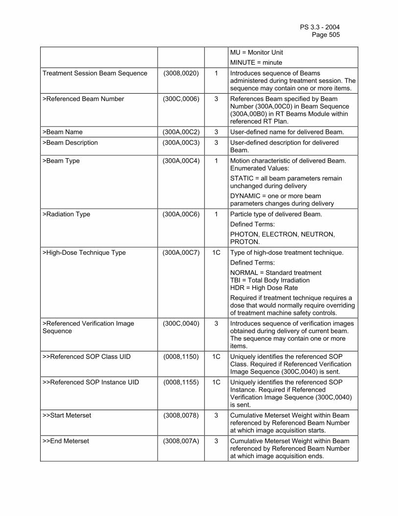
PS 3.3 - 2004 Page 505
MU = Monitor Unit MINUTE = minute
Treatment Session Beam Sequence (3008,0020) 1 Introduces sequence of Beams administered during treatment session. The sequence may contain one or more items.
>Referenced Beam Number (300C,0006) 3 References Beam specified by Beam Number (300A,00C0) in Beam Sequence (300A,00B0) in RT Beams Module within referenced RT Plan.
>Beam Name (300A,00C2) 3 User-defined name for delivered Beam. >Beam Description (300A,00C3) 3 User-defined description for delivered
Beam. >Beam Type (300A,00C4) 1 Motion characteristic of delivered Beam.
Enumerated Values: STATIC = all beam parameters remain unchanged during delivery DYNAMIC = one or more beam parameters changes during delivery
>Radiation Type (300A,00C6) 1 Particle type of delivered Beam. Defined Terms: PHOTON, ELECTRON, NEUTRON, PROTON.
>High-Dose Technique Type (300A,00C7) 1C Type of high-dose treatment technique. Defined Terms: NORMAL = Standard treatment TBI = Total Body Irradiation HDR = High Dose Rate Required if treatment technique requires a dose that would normally require overriding of treatment machine safety controls.
>Referenced Verification Image Sequence
(300C,0040) 3 Introduces sequence of verification images obtained during delivery of current beam. The sequence may contain one or more items.
>>Referenced SOP Class UID (0008,1150) 1C Uniquely identifies the referenced SOP Class. Required if Referenced Verification Image Sequence (300C,0040) is sent.
>>Referenced SOP Instance UID (0008,1155) 1C Uniquely identifies the referenced SOP Instance. Required if Referenced Verification Image Sequence (300C,0040) is sent.
>>Start Meterset (3008,0078) 3 Cumulative Meterset Weight within Beam referenced by Referenced Beam Number at which image acquisition starts.
>>End Meterset (3008,007A) 3 Cumulative Meterset Weight within Beam referenced by Referenced Beam Number at which image acquisition ends.

PS 3.3 - 2004 Page 506
>Referenced Measured Dose Reference Sequence
(3008,0080) 3 Introduces sequence of doses measured during treatment delivery for current Beam. The sequence may contain one or more items.
>>Referenced Dose Reference Number
(300C,0051) 1C Uniquely references Dose Reference specified by Dose Reference Number (300A,0012) in Dose Reference Sequence (300A,0010) in RT Prescription Module of referenced RT Plan. Required if Referenced Measured Dose Reference Sequence (3008,0080) is sent and Referenced Measured Dose Reference Number (3008,0082) is not sent. It shall not be present otherwise.
>>Referenced Measured Dose Reference Number
(3008,0082) 1C Uniquely references Measured Dose Reference specified by Measured Dose Reference Number (3008,0064) in Measured Dose Reference Sequence (3008,0010). Required if Referenced Measured Dose Reference Sequence (3008,0080) is sent and Referenced Dose Reference Number (300C, 0051) is not sent. It shall not be present otherwise.
>>Measured Dose Value (3008,0016) 1C Measured Dose in units specified by Dose Units (3004,0002) in sequence referenced by Measured Dose Reference Sequence (3008,0010) or Dose Reference Sequence (300A,0010) in RT Prescription Module of referenced RT Plan as defined above. Required if Referenced Measured Dose Reference Sequence (3008,0080) is sent.
>Referenced Calculated Dose Reference Sequence
(3008,0090) 3 Introduces sequence of doses estimated for each treatment delivery. The sequence may contain one or more items.
>>Referenced Dose Reference Number
(300C,0051) 1C Uniquely identifies Dose Reference specified by Dose Reference Number (300A, 0012) in Dose Reference Sequence (300A, 0010) in RT Prescription Module of referenced RT Plan. Required if Referenced Calculated Dose Reference Sequence (3008,0090) is sent and Referenced Calculated Dose Reference Number (3008,0092) is not sent.
>>Referenced Calculated Dose Reference Number
(3008,0092) 1C Uniquely identifies Calculated Dose Reference specified by Calculated Dose Reference Number (3008,0072) within Calculated Dose Reference Sequence (3008,0070). Required if Referenced Calculated Dose Reference Sequence (3008,0090) is sent and Referenced Dose Reference Number (300C,0051) is not sent.

PS 3.3 - 2004 Page 507
>>Calculated Dose Reference Dose Value
(3008,0076) 1C Calculated Dose (Gy). Required if Referenced Calculated Dose Reference Sequence (3008,0090) is sent.
>Source-Axis Distance (300A,00B4) 3 Radiation source to gantry rotation axis distance of the equipment that was used for beam delivery (mm).
>Beam Limiting Device Leaf Pairs Sequence
(3008,00A0) 1 Introduces sequence of beam limiting device (collimator) jaw or leaf (element) leaf pair values. The sequence may contain one or more items.
>>RT Beam Limiting Device Type (300A,00B8) 1 Type of beam limiting device (collimator). Enumerated Values: X = symmetric jaw pair in IEC X direction Y = symmetric jaw pair in IEC Y direction ASYMX = asymmetric jaw pair in IEC X direction ASYMY = asymmetric pair in IEC Y direction MLCX = multileaf (multi-element) jaw pair in IEC X direction MLCY = multileaf (multi-element) jaw pair in IEC Y direction
>>Number of Leaf/Jaw Pairs (300A,00BC) 1 Number of leaf (element) or jaw pairs (equal to 1 for standard beam limiting device jaws).
>Referenced Patient Setup Number (300C,006A) 3 Uniquely identifies Patient Setup used within current beam, specified by Patient Setup Number (300A, 0182) within Patient Setup Sequence (300A, 0180) of RT Treatment Record.
>Number of Wedges (300A,00D0) 1 Number of wedges associated with current delivered Beam.
>Recorded Wedge Sequence (3008,00B0) 1C Introduces sequence of treatment wedges present during delivered Beam. Required if Number of Wedges (300A,00D0) is non-zero. The sequence may contain one or more items.
>>Wedge Number (300A,00D2) 3 Identification number of the Wedge. The value of Wedge Number (300A,00D2) shall be unique within the wedge sequence.
>>Wedge Type (300A,00D3) 2C Type of wedge defined for delivered Beam. Required if Recorded Wedge Sequence (3008,00B0) is sent. Defined Terms: STANDARD = standard (static) wedge DYNAMIC = moving Beam Limiting Device (collimator) jaw simulating wedge

PS 3.3 - 2004 Page 508
MOTORIZED = single wedge which can be removed from beam remotely
>>Wedge ID (300A,00D4) 3 User-supplied identifier for wedge. >>Accessory Code (300A,00F9) 3 An identifier for the accessory intended to
be read by a device such as a bar-code reader.
>>Wedge Angle (300A,00D5) 3 Nominal wedge angle delivered (degrees). >>Wedge Orientation (300A,00D8) 3 Orientation of wedge, i.e. orientation of IEC
WEDGE FILTER coordinate system with respect to IEC BEAM LIMITING DEVICE coordinate system (degrees).
>Number of Compensators (300A,00E0) 2 Number of compensators associated with current delivered Beam.
>Recorded Compensator Sequence (3008,00C0) 3 Introduces sequence of treatment compensators associated with current Beam. The sequence may contain one or more items.
>>Referenced Compensator Number (300C,00D0) 1C Uniquely identifies compensator specified by Compensator Number (300A,00E4) within Beam referenced by Referenced Beam Number (300C,0006). Required if Recorded Compensator Sequence (3008,00C0) is sent.
>>Compensator Type (300A,00EE) 2C Type of compensator (if any). Required if Recorded Compensator Sequence (3008,00C0) is sent. Defined Terms: STANDARD = physical (static) compensator DYNAMIC = moving Beam Limiting Device (collimator) simulating compensator
>>Compensator ID (300A,00E5) 3 User-supplied identifier for compensator. >>Accessory Code (300A,00F9) 3 An identifier for the accessory intended to
be read by a device such as a bar-code reader.
>Number of Boli (300A,00ED) 2 Number of boli used with current Beam. >Referenced Bolus Sequence (300C,00B0) 3 Introduces sequence of boli associated
with Beam. The sequence may contain one or more items.
>>Referenced ROI Number (3006,0084) 1C Uniquely identifies ROI representing the bolus specified by ROI Number (3006,0022) in Structure Set ROI Sequence (3006,0020) in Structure Set Module within RT Structure Set IOD referenced by referenced RT Plan in Referenced RT Plan Sequence (300C,0002) in RT General Treatment Record Module. Required if Referenced Bolus Sequence (300C,00B0) is sent.

PS 3.3 - 2004 Page 509
>>Accessory Code (300A,00F9) 3 An identifier for the accessory intended to be read by a device such as a bar-code reader.
>Number of Blocks (300A,00F0) 2 Number of shielding blocks or Electron Inserts associated with Beam.
>Recorded Block Sequence (3008,00D0) 3 Introduces sequence of blocks associated with current Beam. The sequence may contain one or more items.
>>Block Tray ID (300A,00F5) 3 User-supplied identifier for block tray or Electron Insert.
>>Accessory Code (300A,00F9) 3 An identifier for the accessory intended to be read by a device such as a bar-code reader.
>>Referenced Block Number (300C,00E0) 3 Uniquely identifies block specified by Block Number (300A,00FC) within Beam referenced by Referenced Beam Number (300C,0006).
>>Block Name (300A,00FE) 2C User-defined name for block. Required if Recorded Block Sequence (3008,00D0) is sent.
>Applicator Sequence (300A,0107) 3 Introduces sequence of Applicators associated with Beam. Only a single item shall be permitted in this sequence.
>>Applicator ID (300A,0108) 1C User or machine supplied identifier for Applicator. Required if Applicator Sequence (300A,0107) is sent.
>>Accessory Code (300A,00F9) 3 An identifier for the accessory intended to be read by a device such as a bar-code reader.
>>Applicator Type (300A,0109) 1C Type of Applicator. Required if Applicator Sequence (300A,0107) is sent. Defined Terms: ELECTRON_SQUARE = square electron applicator ELECTRON_RECT = rectangular electron applicator ELECTRON_CIRC = circular electron applicator ELECTRON_SHORT = short electron applicator ELECTRON_OPEN = open (dummy) electron applicator INTRAOPERATIVE = intraoperative (custom) applicator STEREOTACTIC = stereotactic applicator
>>Applicator Description (300A,010A) 3 User-defined description for Applicator. >Current Fraction Number (3008,0022) 2 Fraction number for this beam
administration.
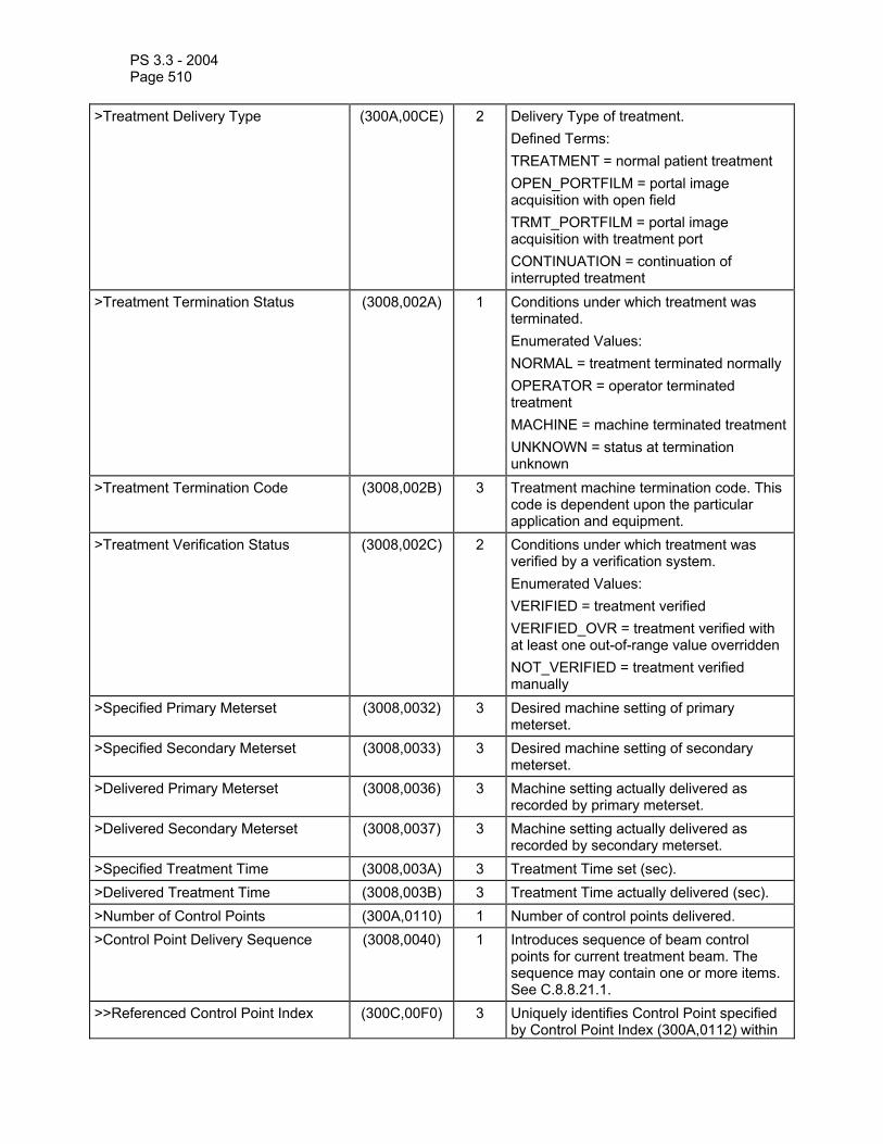
PS 3.3 - 2004 Page 510
>Treatment Delivery Type (300A,00CE) 2 Delivery Type of treatment. Defined Terms: TREATMENT = normal patient treatment OPEN_PORTFILM = portal image acquisition with open field TRMT_PORTFILM = portal image acquisition with treatment port CONTINUATION = continuation of interrupted treatment
>Treatment Termination Status (3008,002A) 1 Conditions under which treatment was terminated. Enumerated Values: NORMAL = treatment terminated normally OPERATOR = operator terminated treatment MACHINE = machine terminated treatmentUNKNOWN = status at termination unknown
>Treatment Termination Code (3008,002B) 3 Treatment machine termination code. This code is dependent upon the particular application and equipment.
>Treatment Verification Status (3008,002C) 2 Conditions under which treatment was verified by a verification system. Enumerated Values: VERIFIED = treatment verified VERIFIED_OVR = treatment verified with at least one out-of-range value overridden NOT_VERIFIED = treatment verified manually
>Specified Primary Meterset (3008,0032) 3 Desired machine setting of primary meterset.
>Specified Secondary Meterset (3008,0033) 3 Desired machine setting of secondary meterset.
>Delivered Primary Meterset (3008,0036) 3 Machine setting actually delivered as recorded by primary meterset.
>Delivered Secondary Meterset (3008,0037) 3 Machine setting actually delivered as recorded by secondary meterset.
>Specified Treatment Time (3008,003A) 3 Treatment Time set (sec). >Delivered Treatment Time (3008,003B) 3 Treatment Time actually delivered (sec). >Number of Control Points (300A,0110) 1 Number of control points delivered. >Control Point Delivery Sequence (3008,0040) 1 Introduces sequence of beam control
points for current treatment beam. The sequence may contain one or more items. See C.8.8.21.1.
>>Referenced Control Point Index (300C,00F0) 3 Uniquely identifies Control Point specified by Control Point Index (300A,0112) within

PS 3.3 - 2004 Page 511
Beam referenced by Referenced Beam Number (300C,0006).
>>Treatment Control Point Date (3008,0024) 1 Date administration of treatment beam began.
>>Treatment Control Point Time (3008,0025) 1 Time administration of treatment beam began.
>>Specified Meterset (3008,0042) 2 Desired machine setting for current control point.
>>Delivered Meterset (3008,0044) 1 Machine setting actually delivered at current control point.
>>Dose Rate Set (300A,0115) 2 Dose Rate set on treatment machine for segment beginning at current control point (meterset/min).
>>Dose Rate Delivered (3008,0048) 2 Dose Rate actually delivered for segment beginning at current control point (meterset/min).
>>Nominal Beam Energy (300A,0114) 3 Nominal Beam Energy at control point. >>Nominal Beam Energy Unit (300A,0015) 1C Units used for Nominal Beam Energy
(300A,0114). Required if Nominal Beam Energy (300A,0114) is sent. Defined Terms: MV = Megavolt MEV = Mega electron-Volt If Radiation Type (300A,00C6) is PHOTON, Nominal Beam Energy Unit (300A,0015) shall be MV. If Radiation Type (300A,00C6) is ELECTRON, Nominal Beam Energy Unit (300A,0015) shall be MEV.
>>Wedge Position Sequence (300A,0116) 3 Introduces sequence of Wedge positions for current control point. The sequence may contain one or more items.
>>>Referenced Wedge Number (300C,00C0) 1C Uniquely identifies wedge specified by Wedge Number (300A,00D2) within Beam referenced by Referenced Beam Number (300C,0006). Required if Wedge Position Sequence (300A,0116) is sent.
>>>Wedge Position (300A,0118) 1C Position of Wedge at current control point. Required if Wedge Position Sequence (300A,0116) is sent. Enumerated Values: IN, OUT.
>>Beam Limiting Device Position Sequence
(300A,011A) 1C Introduces sequence of beam limiting device (collimator) jaw or leaf (element) positions. Required for Control Point 0 of Control Point Delivery Sequence (3008,0040) or if beam limiting device (collimator) changes during beam administration. The sequence may contain

PS 3.3 - 2004 Page 512
one or more items. >>>RT Beam Limiting Device Type (300A,00B8) 1C Type of beam limiting device. The value of
this attribute shall correspond to RT Beam Limiting Device Type (300A,00B8) defined in an element of Beam Limiting Device Leaf Pairs Sequence (3008,00A0). Required if Beam Limiting Device Position Sequence (300A,011A) is sent. Enumerated Values: X = symmetric jaw pair in IEC X direction Y = symmetric jaw pair in IEC Y direction ASYMX = asymmetric jaw pair in IEC X direction ASYMY = asymmetric pair in IEC Y direction MLCX = multileaf (multi-element) jaw pair in IEC X direction MLCY = multileaf (multi-element) jaw pair in IEC Y direction
>>>Leaf/Jaw Positions (300A,011C) 1C Positions of beam limiting device (collimator) leaf (element) or jaw pairs (mm) in IEC BEAM LIMITING DEVICE coordinate axis appropriate to RT Beam Limiting Device Type (300A,00B8), e.g. X-axis for MLCX, Y-axis for MLCY. Contains 2N values, where N is the Number of Leaf/Jaw Pairs (300A,00BC) defined in element of Beam Limiting Device Leaf Pairs Sequence (3008,00A0). Values shall be in IEC leaf subscript order 101, 201, 102, 202, … 1N, 2N. Required if Beam Limiting Device Position Sequence (300A,011A) is sent.
>>Gantry Angle (300A,011E) 1C Treatment machine gantry angle, i.e. orientation of IEC GANTRY coordinate system with respect to IEC FIXED REFERENCE coordinate system (degrees). Required for Control Point 0 of Control Point Delivery Sequence (3008,0040) or if Gantry Angle changes during beam administration.
>>Gantry Rotation Direction (300A,011F) 1C Direction of Gantry Rotation when viewing gantry from isocenter, for segment beginning at current Control Point. Required for Control Point 0 of Control Point Delivery Sequence (3008,0040), or if Gantry Rotation Direction changes during beam administration. Enumerated Values: CW = clockwise

PS 3.3 - 2004 Page 513
CC = counter-clockwise NONE = no rotation
>>Beam Stopper Position (3008,0230) 3 Position of Beam Stopper during beam administration. Enumerated Values: EXTENDED = Beam Stopper extended RETRACTED = Beam Stopper retracted UNKNOWN = Position unknown
>>Beam Limiting Device Angle (300A,0120) 1C Beam Limiting Device (collimator) angle, i.e. orientation of IEC BEAM LIMITING DEVICE coordinate system with respect to IEC GANTRY coordinate system (degrees). Required for Control Point 0 of Control Point Delivery Sequence (3008,0040) or if beam limiting device (collimator) angle changes during beam delivery.
>>Beam Limiting Device Rotation Direction
(300A,0121) 1C Direction of Beam Limiting Device Rotation when viewing beam limiting device (collimator) from radiation source, for segment beginning at current Control Point. Required for Control Point 0 of Control Point Delivery Sequence (3008,0040) or if Beam Limiting Device Rotation Direction changes during beam administration. Enumerated Values: CW = clockwise CC = counter-clockwise NONE = no rotation
>>Patient Support Angle (300A,0122) 1C Patient Support angle, i.e. orientation of IEC PATIENT SUPPORT (turntable) coordinate system with respect to IEC FIXED REFERENCE coordinate system (degrees). Required for Control Point 0 of Control Point Delivery Sequence (3008,0040) or if Patient Support Angle changes during beam administration.
>>Patient Support Rotation Direction (300A,0123) 1C Direction of Patient Support Rotation when viewing table from above, for segment beginning at current Control Point. Required for Control Point 0 of Control Point Delivery Sequence (3008,0040), or if Patient Support Rotation Direction changes during beam administration. Enumerated Values: CW = clockwise CC = counter-clockwise NONE = no rotation

PS 3.3 - 2004 Page 514
>>Table Top Eccentric Axis Distance (300A,0124) 3 Distance (positive) from the IEC PATIENT SUPPORT vertical axis to the IEC TABLE TOP ECCENTRIC vertical axis (mm).
>>Table Top Eccentric Angle (300A,0125) 1C Table Top (non-isocentric) angle, i.e. orientation of IEC TABLE TOP ECCENTRIC coordinate system with respect to IEC PATIENT SUPPORT coordinate system (degrees). Required for Control Point 0 of Control Point Delivery Sequence (3008,0040) or if Table Top Eccentric Angle changes during beam administration.
>>Table Top Eccentric Rotation Direction
(300A,0126) 1C Direction of Table Top Eccentric Rotation when viewing table from above, for segment beginning at current Control Point. Required for Control Point 0 of Control Point Delivery Sequence (3008,0040) or if Table Top Eccentric Rotation Direction changes during beam administration. Enumerated Values: CW = clockwise CC = counter-clockwise NONE = no rotation
>>Table Top Vertical Position (300A,0128) 2C Table Top Vertical position in IEC TABLE TOP coordinate system (mm). This value is interpreted as an absolute, rather than relative, Table setting. Required for Control Point 0 of Control Point Delivery Sequence (3008,0040) or if Table Top Vertical Position changes during beam administration.
>>Table Top Longitudinal Position (300A,0129) 2C Table Top Longitudinal position in IEC TABLE TOP coordinate system (mm). This value is interpreted as an absolute, rather than relative, Table setting. Required for Control Point 0 of Control Point Delivery Sequence (3008,0040) or if Table Top Longitudinal Position changes during beam administration.
>>Table Top Lateral Position (300A,012A) 2C Table Top Lateral position in IEC TABLE TOP coordinate system (mm). This value is interpreted as an absolute, rather than relative, Table setting. Required for Control Point 0 of Control Point Delivery Sequence (3008,0040) or if Table Top Lateral Position changes during beam administration.
>>Override Sequence (3008,0060) 3 Introduces sequence of parameters which were overridden during the administration of the beam segment immediately prior to the current control point. The sequence

PS 3.3 - 2004 Page 515
may contain one or more items. >>>Override Parameter Pointer (3008,0062) 2C Contains the Data Element Tag of the
attribute which was overridden. Required if Override Sequence (3008,0060) is sent.
>>>Operator Name (0008,1070) 2C Name of operator who authorized override. Required if Override Sequence (3008,0060) is sent.
>>>Override Reason (3008,0066) 3 User-defined description of reason for override of parameter specified by Override Parameter Pointer (3008,0062).
C.8.8.21.1 Control point machine delivery parameters All treatment machine delivery parameters (including table angles and positions) in the RT Treatment Session Record Module shall be specified as absolute, not relative, values at the Control Point.
C.8.8.22 RT Brachy Session Record Module Table C.8-58—RT BRACHY SESSION RECORD MODULE ATTRIBUTES
Attribute Name Tag Type Attribute Description Operator Name (0008,1070) 2 Name of operator administering treatment
session. Referenced Fraction Group Number (300C,0022) 3 Identifier of Fraction Group within
referenced RT Plan. Number of Fractions Planned (300A,0078) 2 Total number of treatments (Fractions)
planned for current Fraction Group. Brachy Treatment Technique (300A,0200) 1 Type of brachytherapy treatment
technique. Enumerated Values: INTRALUMENARY, INTRACAVITARY, INTERSTITIAL, CONTACT, INTRAVASCULAR, PERMANENT. See RT Plan IOD.
Brachy Treatment Type (300A,0202) 1 Type of brachytherapy treatment. Defined Terms: MANUAL = manually positioned HDR = High dose rate MDR = Medium dose rate LDR = Low dose rate PDR = Pulsed dose rate
Recorded Source Sequence (3008,0100) 1 Introduces sequence of Sources to be used within Application Setups. The sequence may contain one or more items.
>Source Number (300A,0212) 1 Identification number of the Source. The value of Source Number (300A,0212) shall be unique within the Recorded Source Sequence (3008,0100) in which it is created.
>Source Type (300A,0214) 1 Type of Source. Defined Terms: POINT,

PS 3.3 - 2004 Page 516
LINE, CYLINDER, SPHERE. >Source Manufacturer (300A,0216) 2 Manufacturer of source. >Source Serial Number (3008,0105) 2 Serial Number of source. >Source Isotope Name (300A,0226) 1 User-defined name of Isotope. >Source Isotope Half Life (300A,0228) 1 Half-life of Isotope (days). >Reference Air Kerma Rate (300A,022A) 1 Air Kerma Rate in air of Isotope specified
at Air Kerma Rate Reference Date (300A,022C) and Air Kerma Rate Reference Time (300A,022E) (in µGy h-1 at 1 m).
>Air Kerma Rate Reference Date (300A,022C) 1 Reference date of Reference Air Kerma Rate (300A,022A) of Isotope.
>Air Kerma Rate Reference Time (300A,022E) 1 Reference time of Air Kerma Rate (300A,022A) of Isotope.
Treatment Session Application Setup Sequence
(3008,0110) 1 Introduces sequence of Application Setups for RT Treatment Record for current RT Plan. The sequence may contain one or more items.
>Application Setup Type (300A,0232) 1 Type of Application Setup. Defined Terms: FLETCHER_SUIT, DELCLOS, BLOEDORN, JOSLIN_FLYNN, CHANDIGARH, MANCHESTER, HENSCHKE, NASOPHARYNGEAL, OESOPHAGEAL, ENDOBRONCHIAL, SYED_NEBLETT, ENDORECTAL, PERINEAL.
>Referenced Brachy Application Setup Number
(300C,000C) 3 References application setup specified by Application Setup Number (300A,0234) in Application Setup Sequence (300A,0230) in RT Brachy Applications Module within referenced RT Plan.
>Application Setup Name (300A,0236) 3 User-defined name for Application Setup. >Application Setup Manufacturer (300A,0238) 3 Manufacturer of Application Setup. >Template Number (300A,0240) 3 Identification number of the Template. >Template Type (300A,0242) 3 User-defined type for Template Device. >Template Name (300A,0244) 3 User-defined name for Template Device. >Application Setup Check (3008,0116) 3 Results of check-wire travel through all
channels of current Application Setup. Enumerated Values: PASSED = Passed check FAILED = Failed check UNKNOWN = Unknown status
>Referenced Verification Image Sequence
(300C,0040) 3 Introduces sequence of verification images obtained during delivery of current beam. The sequence may contain one or more items. See Note.
>>Referenced SOP Class UID (0008,1150) 1C Uniquely identifies the referenced SOP

PS 3.3 - 2004 Page 517
Class. Required if Referenced Verification Image Sequence (300C,0040) is sent.
>>Referenced SOP Instance UID (0008,1155) 1C Uniquely identifies the referenced SOP Instance. Required if Referenced Verification Image Sequence (300C,0040) is sent.
>Total Reference Air Kerma (300A,0250) 1 Total Reference Air Kerma for current Application Setup, i.e. the sum of the products of the Air Kerma Rates of each Source in each Channel with its respective Channel Time (µGy at 1 m).
>Referenced Measured Dose Reference Sequence
(3008,0080) 3 Introduces sequence of doses measured during treatment delivery, summed over entire session. The sequence may contain one or more items.
>>Referenced Dose Reference Number
(300C,0051) 1C Uniquely references Dose Reference specified by Dose Reference Number (300A,0012) in Dose Reference Sequence (300A,0010) in RT Prescription Module of referenced RT Plan. Required if Referenced Measured Dose Reference Sequence (3008,0080) is sent and Referenced Measured Dose Reference Number (3008,0082) is not sent. It shall not be present otherwise.
>>Referenced Measured Dose Reference Number
(3008,0082) 1C Uniquely references Measured Dose Reference specified by Measured Dose Reference Number (3008,0064) in Measured Dose Reference Sequence (3008,0010). Required if Referenced Measured Dose Reference Sequence (3008,0080) is sent and Referenced Dose Reference Number (300C,0051) is not sent. It shall not be present otherwise.
>>Measured Dose Value (3008,0016) 1C Measured Dose in units specified by Dose Units (3004,0002) in sequence referenced by Measured Dose Reference Sequence (3008,0010) or Dose Reference Sequence (300A,0010) in RT Prescription Module of referenced RT Plan as defined above. Required if Referenced Measured Dose Reference Sequence (3008,0080) is sent.
>Referenced Calculated Dose Reference Sequence
(3008,0090) 3 Introduces sequence of doses estimated for each treatment delivery. The sequence may contain one or more items.
>>Referenced Dose Reference Number
(300C,0051) 1C Uniquely identifies Dose Reference specified by Dose Reference Number (300A,0012) in Dose Reference Sequence (300A,0010) in RT Prescription Module of referenced RT Plan. Required if Referenced Calculated Dose Reference Sequence (3008,0090) is sent and

PS 3.3 - 2004 Page 518
Referenced Calculated Dose Reference Number (3008,0092) is not sent. It shall not be present otherwise.
>>Referenced Calculated Dose Reference Number
(3008,0092) 1C Uniquely identifies Calculated Dose Reference specified by Calculated Dose Reference Number (3008,0072) within Calculated Dose Reference Sequence (3008,0070). Required if Referenced Calculated Dose Reference Sequence (3008,0090) is sent and Referenced Dose Reference Number (300C,0051) is not sent. It shall not be present otherwise.
>>Calculated Dose Reference Dose Value
(3008,0076) 1C Calculated Dose (Gy). Required if Referenced Calculated Dose Reference Sequence (3008,0090) is sent.
>Current Fraction Number (3008,0022) 2 Fraction number for this application setup. >Treatment Delivery Type (300A,00CE) 2 Delivery Type of treatment.
Defined Terms: TREATMENT = normal patient treatment CONTINUATION = continuation of interrupted treatment
>Treatment Termination Status (3008,002A) 1 Conditions under which treatment was terminated. Enumerated Values: NORMAL = treatment terminated normally OPERATOR = operator terminated treatment MACHINE = machine terminated treatment for other than NORMAL condition UNKNOWN = status at termination unknown
>Treatment Termination Code (3008,002B) 3 Treatment machine termination code. This code is dependent upon the particular application and equipment.
>Treatment Verification Status (3008,002C) 2 Conditions under which treatment was verified by a verification system. Enumerated Values: VERIFIED = treatment verified VERIFIED_OVR = treatment verified with at least one out-of-range value overridden NOT_VERIFIED = treatment verified manually
>Recorded Brachy Accessory Device Sequence
(3008,0120) 3 Introduces sequence of Brachy Accessory Devices associated with current Application Setup. The sequence may contain one or more items.
>>Referenced Brachy Accessory Device Number
(3008,0122) 2C Identification number of the Brachy Accessory Device. The value of Brachy

PS 3.3 - 2004 Page 519
Accessory Device Number (300A,0262) shall be unique within the Application Setup in which it is created. Required if Recorded Brachy Accessory Device Sequence (3008,0120) is sent.
>>Brachy Accessory Device ID (300A,0263) 2C User or machine supplied identifier for Brachy Accessory Device. Required if Recorded Brachy Accessory Device Sequence (3008,0120) is sent.
>>Brachy Accessory Device Type (300A,0264) 1C Type of Brachy Accessory Device. Required if Recorded Brachy Accessory Device Sequence (3008,0120) is sent. Defined Terms: SHIELD, DILATATION, MOLD, PLAQUE, FLAB.
>>Brachy Accessory Device Name (300A,0266) 3 User-defined name for Brachy Accessory Device.
>Recorded Channel Sequence (3008,0130) 1 Introduces sequence of Channels for current Application Setup. The sequence may contain one or more items.
>>Channel Number (300A,0282) 1 Identification number of the Channel. The value of Channel Number (300A,0282) shall be unique within the Application Setup in which it is created.
>>Channel Length (300A,0284) 2 Length of Channel (mm). See RT Plan IOD.
>>Specified Channel Total Time (3008,0132) 1 Total amount of time specified between Control Point 0 and final Control Point of the Brachy Control Point Sequence (300A,02D0) for current Channel (sec).
>>Delivered Channel Total Time (3008,0134) 1 Total amount of time actually delivered between Control Point 0 and final Control Point of the Brachy Control Point Sequence (300A,02D0) for current Channel (sec).
>>Source Movement Type (300A,0288) 1 Type of Source movement. Defined Terms: STEPWISE, FIXED, OSCILLATING, UNIDIRECTIONAL.
>>Specified Number of Pulses (3008,0136) 1C Number of Pulses specified per fraction for current Channel. Required if Brachy Treatment Type (300A,0202) is PDR. See C.8.8.22.1.
>>Delivered Number of Pulses (3008,0138) 1C Number of Pulses actually delivered per fraction for current Channel. Required if Brachy Treatment Type (300A,0202) is PDR. See C.8.8.22.1.
>>Specified Pulse Repetition Interval (3008,013A) 1C Pulse repetition interval (sec) specified for current Channel. Required if Brachy Treatment Type (300A,0202) is PDR. See C.8.8.22.1
>>Delivered Pulse Repetition Interval (3008,013C) 1C Pulse repetition interval (sec) actually

PS 3.3 - 2004 Page 520
delivered for current Channel. Required if Brachy Treatment Type (300A,0202) is PDR. See C.8.8.22.1.
>>Referenced Measured Dose Reference Sequence
(3008,0080) 3 Introduces sequence of doses measured during treatment delivery, summed over entire session. The sequence may contain one or more items.
>>>Referenced Dose Reference Number
(300C,0051) 1C Uniquely references Dose Reference specified by Dose Reference Number (300A,0012) in Dose Reference Sequence (300A,0010) in RT Prescription Module of referenced RT Plan. Required if Referenced Measured Dose Reference Sequence (3008,0080) is sent and Referenced Measured Dose Reference Number (3008,0082) is not sent. It shall not be present otherwise.
>>>Referenced Measured Dose Reference Number
(3008,0082) 1C References Measured Dose Reference specified by Measured Dose Reference Number (3008,0064) in Measured Dose Reference Sequence (3008,0010). Required if Referenced Measured Dose Reference Sequence (3008,0080) is sent and Referenced Dose Reference Number (300C, 0051) is not sent. It shall not be present otherwise.
>>>Measured Dose Value (3008,0016) 1C Measured Dose. Required if Referenced Measured Dose Reference Sequence (3008,0080) is sent.
>>Referenced Calculated Dose Reference Sequence
(3008,0090) 3 Introduces sequence of doses estimated for each treatment delivery. The sequence may contain one or more items.
>>>Referenced Dose Reference Number
(300C,0051) 1C Uniquely identifies Dose Reference specified by Dose Reference Number (300A,0012) in Dose Reference Sequence (300A,0010) in RT Prescription Module of referenced RT Plan. Required if Referenced Calculated Dose Reference Sequence (3008,0090) is sent and Referenced Calculated Dose Reference Number (3008,0092) is not sent. It shall not be present otherwise.
>>>Referenced Calculated Dose Reference Number
(3008,0092) 1C Uniquely identifies Calculated Dose Reference specified by Calculated Dose Reference Number (3008,0072) within Calculated Dose Reference Sequence (3008,0070). Required if Referenced Calculated Dose Reference Sequence (3008,0090) is sent and Referenced Dose Reference Number (300C,0051) is not sent. It shall not be present otherwise.
>>>Calculated Dose Reference Dose (3008,0076) 1C Calculated Dose (Gy). Required if

PS 3.3 - 2004 Page 521
Value Referenced Calculated Dose Reference Sequence (3008,0090) is sent.
>>Recorded Source Applicator Sequence
(3008,0140) 3 Introduces sequence of recorded Source Applicators. The sequence may contain one or more items.
>>>Referenced Source Applicator Number
(3008,0142) 2 Identification number of the Source Applicator. The value of Source Applicator Number (300A,0290) shall be unique within the Channel in which it is created.
>>>Source Applicator ID (300A,0291) 2C User or machine supplied identifier for Source Applicator. Required if Recorded Source Applicator Sequence (3008,0140) is sent.
>>>Source Applicator Type (300A,0292) 1C Type of Source Applicator. Required if Recorded Source Applicator Sequence (3008,0140) is sent. Enumerated Values: FLEXIBLE, RIGID.
>>>Source Applicator Name (300A,0294) 3 User-defined name for Source Applicator. >>>Source Applicator Length (300A,0296) 1C Length of Source Applicator (mm), defined
as the distance between the connector of the applicator and the distal-most position of the source. Required if Recorded Source Applicator Sequence (3008,0140) is sent.
>>>Source Applicator Manufacturer (300A,0298) 3 Manufacturer of Source Applicator. >>>Source Applicator Step Size (300A,02A0) 1C Distance of path along channel (mm)
between adjacent (potential) dwell positions. Required if Source Movement Type (300A,0288) is STEPWISE.
>>Transfer Tube Number (300A,02A2) 2 Identification number of the Transfer Tube. The value of Transfer Tube Number (300A,02A2) shall be unique within the Channel in which it is created.
>>Transfer Tube Length (300A,02A4) 2C Length of Transfer Tube of current afterloading Channel (mm). Required if value Transfer Tube Number (300A,02A2) is not zero length.
>>Recorded Channel Shield Sequence
(3008,0150) 3 Introduces sequence of Channel Shields associated with current Channel. The sequence may contain one or more items. See RT Plan IOD for description of Channel Shields.
>>>Referenced Channel Shield Number
(3008,0152) 2C Identification number of the Channel Shield. The value of Channel Shield Number (300A,02B2) shall be unique within the Channel in which it is created. Required if Recorded Channel Shield Sequence (3008,0150) is sent.
>>>Channel Shield ID (300A,02B3) 2C User or machine supplied identifier for Channel Shield. Required if Recorded Channel Shield Sequence (3008,0150) is
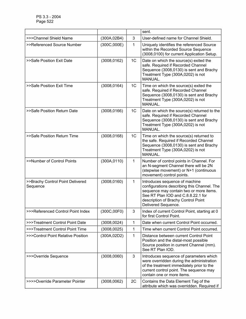
PS 3.3 - 2004 Page 522
sent. >>>Channel Shield Name (300A,02B4) 3 User-defined name for Channel Shield. >>Referenced Source Number (300C,000E) 1 Uniquely identifies the referenced Source
within the Recorded Source Sequence (3008,0100) for current Application Setup.
>>Safe Position Exit Date (3008,0162) 1C Date on which the source(s) exited the safe. Required if Recorded Channel Sequence (3008,0130) is sent and Brachy Treatment Type (300A,0202) is not MANUAL.
>>Safe Position Exit Time (3008,0164) 1C Time on which the source(s) exited the safe. Required if Recorded Channel Sequence (3008,0130) is sent and Brachy Treatment Type (300A,0202) is not MANUAL.
>>Safe Position Return Date (3008,0166) 1C Date on which the source(s) returned to the safe. Required if Recorded Channel Sequence (3008,0130) is sent and Brachy Treatment Type (300A,0202) is not MANUAL.
>>Safe Position Return Time (3008,0168) 1C Time on which the source(s) returned to the safe. Required if Recorded Channel Sequence (3008,0130) is sent and Brachy Treatment Type (300A,0202) is not MANUAL.
>>Number of Control Points (300A,0110) 1 Number of control points in Channel. For an N-segment Channel there will be 2N (stepwise movement) or N+1 (continuous movement) control points.
>>Brachy Control Point Delivered Sequence
(3008,0160) 1 Introduces sequence of machine configurations describing this Channel. The sequence may contain two or more items. See RT Plan IOD and C.8.8.22.1 for description of Brachy Control Point Delivered Sequence.
>>>Referenced Control Point Index (300C,00F0) 3 Index of current Control Point, starting at 0 for first Control Point.
>>>Treatment Control Point Date (3008,0024) 1 Date when current Control Point occurred. >>>Treatment Control Point Time (3008,0025) 1 Time when current Control Point occurred. >>>Control Point Relative Position (300A,02D2) 1 Distance between current Control Point
Position and the distal-most possible Source position in current Channel (mm). See RT Plan IOD.
>>>Override Sequence (3008,0060) 3 Introduces sequence of parameters which were overridden during the administration of the treatment immediately prior to the current control point. The sequence may contain one or more items.
>>>>Override Parameter Pointer (3008,0062) 2C Contains the Data Element Tag of the attribute which was overridden. Required if

PS 3.3 - 2004 Page 523
Override Sequence (3008,0060) is sent. >>>>Operator Name (0008,1070) 2C Name of operator who authorized override.
Required if Override Sequence (3008,0060) is sent.
>>>>Override Reason (3008,0066) 3 User-defined description of reason for override of parameter specified by Override Parameter Pointer (3008,0062).
Note: The Referenced Verification Image Sequence (300C,0040) may contain either images taken specifically for verification of the brachy application setup or reference images used in place of verification images, as might be done in HDR treatment planning.
C.8.8.22.1 PDR (Pulsed Dose Rate) Treatment In Brachytherapy treatment techniques where Brachy Treatment Type (300A,0202) is PDR, the Brachy Control Point Sequence (300A,02D0) shall consist of 2N items, where N = Delivered Number of Pulses (3008,0138). Each control point pair shall specify the start and end of a single pulse.
C.8.8.23 RT Treatment Summary Record Module Table C.8-59—RT TREATMENT SUMMARY RECORD MODULE ATTRIBUTES
Attribute Name Tag Type Attribute Description Current Treatment Status (3008,0200) 1 Status of the Treatment at the time the
Treatment Summary was created. Enumerated Values: NOT_STARTED, ON_TREATMENT, ON_BREAK, SUSPENDED, STOPPED, COMPLETED. See C.8.8.23.1.
Treatment Status Comment (3008,0202) 3 Comment on current treatment status. First Treatment Date (3008,0054) 2 Date of delivery of the first treatment. Most Recent Treatment Date (3008,0056) 2 Date of delivery of the most recent
administration. Fraction Group Summary Sequence (3008,0220) 3 Introduces sequence describing current
state of planned vs. delivered fraction groups. The sequence may contain one or more items.
>Referenced Fraction Group Number (300C,0022) 3 References Fraction Group Number (300A,0071) in Fraction Group Sequence (300A,0070) in the referenced RT Plan.
>Fraction Group Type (3008,0224) 2C Indicates type of fraction group. Required if Fraction Group Summary Sequence (3008,0220) is sent. Enumerated Values: EXTERNAL_BEAM, BRACHY.
>Number of Fractions Planned (300A,0078) 2C Number of fractions planned for this fraction group. Required if Fraction Group Summary Sequence (3008,0220) is sent.
>Number of Fractions Delivered (3008,005A) 2C Number of fractions delivered as of Treatment Summary Report. Required if Fraction Group Summary Sequence (3008,0220) is sent.

PS 3.3 - 2004 Page 524
>Fraction Status Summary Sequence (3008,0240) 3 Introduces sequence describing status of fractions in Fraction Group. The sequence may contain one or more items.
>>Referenced Fraction Number (3008,0223) 1C Identifies fraction. Required if Fraction Status Summary Sequence (3008,0240) is sent.
>>Treatment Date (3008,0250) 2C Date when fraction was delivered. Required if Fraction Status Summary Sequence (3008,0240) is sent.
>>Treatment Time (3008,0251) 2C Time when fraction was delivered. Required if Fraction Status Summary Sequence (3008,0240) is sent.
>>Treatment Termination Status (3008,002A) 2C Conditions under which treatment was terminated. Required if Fraction Status Summary Sequence (3008,0240) is sent. Enumerated Values: NORMAL = treatment terminated normally OPERATOR = operator terminated treatment MACHINE = machine terminated treatment for other than NORMAL condition UNKNOWN = status at termination unknown
Treatment Summary Measured Dose Reference Sequence
(3008,00E0) 3 Introduces sequence of references to Measured Dose References. The sequence may contain one or more items.
>Referenced Dose Reference Number (300C,0051) 3 Uniquely identifies Dose Reference specified by Dose Reference Number (300A,0012) in Dose Reference Sequence (300A,0010) in RT Prescription Module of referenced RT Plan referenced in Referenced RT Plan Sequence (300C,0002) of RT General Treatment Record Module.
>Dose Reference Description (300A,0016) 3 User-defined description of Dose Reference.
>Cumulative Dose to Dose Reference (3008,0052) 1C Cumulative Dose delivered to Dose Reference (Gy). Required if Treatment Summary Dose Reference Sequence (3008,00E0) is sent.
Treatment Summary Calculated Dose Reference Sequence
(3008,0050) 3 Introduces sequence of references to Calculated Dose References. The sequence may contain one or more items.
>Referenced Dose Reference Number (300C,0051) 3 Uniquely identifies Dose Reference specified by Dose Reference Number (300A,0012) in Dose Reference Sequence (300A,0010) in RT Prescription Module of referenced RT Plan referenced in Referenced RT Plan Sequence (300C,0002) of RT General Treatment

PS 3.3 - 2004 Page 525
Record Module. >Dose Reference Description (300A,0016) 3 User-defined description of Dose
Reference. >Cumulative Dose to Dose Reference (3008,0052) 1C Cumulative Dose delivered to Dose
Reference (Gy). Required if Treatment Summary Dose Reference Sequence (3008,0050) is sent.
Note: The RT Treatment Summary Record IOD may contain references to related RT Treatment
Session Record IODs. These references are contained within the Referenced Treatment Record Sequence (3008,0030) of the RT General Treatment Record Module.
C.8.8.23.1 Current Treatment Status The definition of the enumerated values for Current Treatment Status (3008,0200) are defined as follows:
NOT_STARTED Patient has not yet begun treatment.
ON_TREATMENT Patient is currently undergoing treatment.
ON_BREAK Patient is currently not undergoing treatment, but a resumption date is known.
SUSPENDED Patient is currently not undergoing treatment, but resumption of treatment is planned at an unknown date.
STOPPED Patient has stopped treatment without completing the planned course.
COMPLETED Patient completed the planned course of treatment.
A change in the Current Treatment Status (or any other field) in a RT Treatment Summary Record Object shall define a new instance of the RT Treatment Summary Record IOD.

PS 3.3 - 2004 Page 526
C.8.9 PET Information Module Definitions This Section describes Positron Emission Tomography series and image Modules. These Modules contain Attributes that are specific to Positron Emission Tomography images.
C.8.9.1 PET Series Module Table C.8-60 contains IOD Attributes that describe a PET Series.
Table C.8-60 - PET SERIES MODULE ATTRIBUTES Attribute Name Tag Type Attribute Description Series Date (0008,0021) 1 Date the Series started. See C.8.9.1.1.2
for specialization. Series Time (0008,0031) 1 Time the Series started. See C.8.9.1.1.2
for specialization. Units (0054,1001) 1 Pixel value units. See C.8.9.1.1.3 for
explanation. Defined terms: CNTS, NONE, CM2, PCNT, CPS, BQML, MGMINML, UMOLMINML, MLMING, MLG, 1CM, UMOLML, PROPCNTS, PROPCPS, MLMINML, MLML, GML, STDDEV
Counts Source (0054,1002) 1 The primary source of counts. The primary source leads to the underlying image Units (0054,1001), as opposed to secondary sources which are used during reconstruction correction. Enumerated Values: EMISSION TRANSMISSION
Series Type (0054,1000) 1 A multi-valued indicator of the type of Series. See C.8.9.1.1.4 for explanation. Value 1 Enumerated Values: STATIC DYNAMIC GATED WHOLE BODY Value 2 Enumerated Values: IMAGE REPROJECTION
Reprojection Method (0054,1004) 2C Method for projecting volumetric data onto planar projection. Required if Series Type (0054,1000), Value 2 is REPROJECTION. Defined terms: SUM MAX PIXEL
Number of R-R Intervals (0054,0061) 1C The maximum number of R-R Intervals that may exist in this Series. Required if Series Type (0054,1000), Value 1 is GATED.
Number of Time Slots (0054,0071) 1C The maximum number of Time Slots that may exist in this Series. Required if Series Type (0054,1000), Value 1 is GATED.

PS 3.3 - 2004 Page 527
Number of Time Slices (0054,0101) 1C The maximum number of Time Slices that may exist in this Series. Required if Series Type (0054,1000), Value 1 is DYNAMIC.
Number of Slices (0054,0081) 1 The maximum number of Slices that may exist in this Series.
Corrected Image (0028,0051) 2 A value that indicates which, if any, corrections have been applied to the images in this series. Defined terms: DECY=decay corrected ATTN=attenuation corrected SCAT=scatter corrected DTIM=dead time corrected MOTN=gantry motion corrected (e.g. wobble, clamshell) PMOT=patient motion corrected CLN=count loss normalization (correction for count loss in gated Time Slots). RAN=randoms corrected RADL=non-uniform radial sampling corrected DCAL=sensitivity calibrated using dose calibrator NORM=detector normalization
Randoms Correction Method (0054,1100) 3 Type of randoms correction processing. Defined terms: NONE = no randoms correction DLYD = delayed event subtraction SING = singles estimation
Attenuation Correction Method (0054,1101) 3 A textual description of the attenuation correction processing. e.g. measured vs. calculated, transmission source type (ring, line, point), assumed patient geometry (polygon, ellipse, segmented, attenuation coefficient, skull thickness), post-injection transmission, smoothing.
Scatter Correction Method (0054,1105) 3 A textual description of the scatter correction processing. e.g. convolution-subtraction, dual energy window, model-based, use of attenuation data.
Decay Correction (0054,1102) 1 The real-world event to which images in this Series were decay corrected. See C.8.9.1.1.5 for explanation. Defined terms: NONE = no decay correction START= acquisition start time ADMIN = radiopharmaceutical administration time
Reconstruction Diameter (0018,1100) 3 Diameter, in mm, of the region within which the data was used in creating the reconstruction of the image. Data may exist outside this region and portions of the

PS 3.3 - 2004 Page 528
patient may exist outside this region. Convolution Kernel (0018,1210) 3 Textual description of the convolution
kernel(s) used to reconstruct the data (e.g. name, cutoff, radial/axial/angular, mathematical form, DC handling)
Reconstruction Method (0054,1103) 3 Textual description of reconstruction processing, e.g. 2D filtered backprojection, 2D iterative, 3D PROMIS, 3D FAVOR, 3D iterative.
Detector Lines of Response Used (0054,1104) 3 Textual description of which detector lines of response were used, mashed, or otherwise processed during tomographic reconstruction.
Acquisition Start Condition (0018,0073) 3 Description of how the data collection was started. Defined terms: DENS = density (counts/sec) RDD = relative density difference (change in counts/sec) MANU = manual TIME = time AUTO = automatic, when ready TRIG = physiological trigger See C.8.9.1.1.6 for explanation.
Acquisition Start Condition Data (0018,0074) 3 Count density, change in count density, or physiological triggers causing data collection to start.
Acquisition Termination Condition (0018,0071) 3 Description of how the data collection for the series was stopped. Defined terms: CNTS = counts DENS = density (counts/sec) RDD = relative density difference (change in counts/sec) MANU = manual OVFL = data overflow TIME = time TRIG = physiological trigger See C.8.4.9.1.3 for explanation.
Acquisition Termination Condition Data (0018,0075) 3 Number of counts, count density, change in count density, or physiological triggers causing the termination.
Field of View Shape (0018,1147) 3 Shape of the field of view of the PET camera. Defined Terms: CYLINDRICAL RING HEXAGONAL MULTIPLE PLANAR
Field of View Dimensions (0018,1149) 3 Dimensions of the field of view, in mm. Transverse detector diameter followed by axial width.
Gantry/Detector Tilt (0018,1120) 3 Angle of tilt in degrees of the gantry. See C.8.9.1.1.7 for explanation.

PS 3.3 - 2004 Page 529
Gantry/Detector Slew (0018,1121) 3 Angle of slew in degrees of the gantry. Positive slew is moving the gantry on the patient’s left toward the patient’s superior, when the patient is supine.
Type of Detector Motion (0054,0202) 3 Describes the detector motion during acquisition. Defined Terms: NONE = stationary gantry STEP AND SHOOT = Interrupted motion, acquire only while stationary CONTINUOUS = Gantry motion and acquisition are simultaneous and continuous WOBBLE = wobble motion CLAMSHELL = clamshell motion
Collimator Type (0018,1181) 2 Collimator Type. Defined Terms: NONE = no collimator RING = transverse septa
Collimator/Grid Name (0018,1180) 3 Label describing the collimator used. Axial Acceptance (0054,1200) 3 Maximum axial angle accepted, in degrees.Axial Mash (0054,1201) 3 Number of adjacent axial lines of response
mashed together. See C.8.9.1.1.8 for explanation.
Transverse Mash (0054,1202) 3 Number of adjacent transverse lines of response mashed together. See C.8.9.1.1.9 for explanation.
Detector Element Size (0054,1203) 3 Size of an individual detector element, in mm. Transverse dimension followed by axial dimension. For a discrete crystal, this is the crystal size. For a continuous detector, this is the pixel bin size.
Coincidence Window Width (0054,1210) 3 The width of the coincidence timing window, in nsec. The maximum time difference accepted between two single events.
Energy Window Range Sequence (0054,0013) 3 Sequence of Repeating Items that describes the energy windows used for this Series. This sequence may contain zero or more items. See C.8.9.1.1.10 for explanation.
>Energy Window Lower Limit (0054,0014) 3 The lower limit of the energy window, in KeV.
>Energy Window Upper Limit (0054,0015) 3 The upper limit of the energy window, in KeV.
Secondary Counts Type (0054,1220) 3 Array defining the type of additional counts accumulated during acquisition. Defined terms: DLYD=delayed events SCAT=scattered events in secondary window
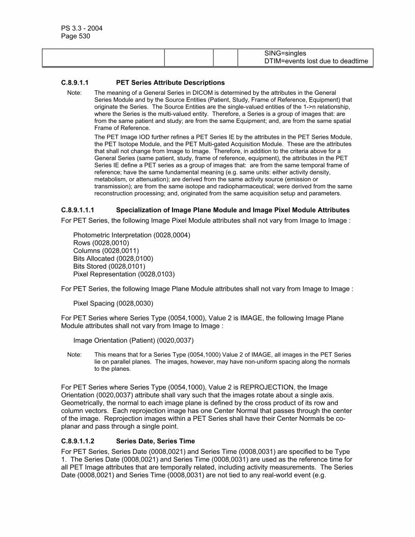
PS 3.3 - 2004 Page 530
SING=singles DTIM=events lost due to deadtime
C.8.9.1.1 PET Series Attribute Descriptions Note: The meaning of a General Series in DICOM is determined by the attributes in the General
Series Module and by the Source Entities (Patient, Study, Frame of Reference, Equipment) that originate the Series. The Source Entities are the single-valued entities of the 1->n relationship, where the Series is the multi-valued entity. Therefore, a Series is a group of images that: are from the same patient and study; are from the same Equipment; and, are from the same spatial Frame of Reference.
The PET Image IOD further refines a PET Series IE by the attributes in the PET Series Module, the PET Isotope Module, and the PET Multi-gated Acquisition Module. These are the attributes that shall not change from Image to Image. Therefore, in addition to the criteria above for a General Series (same patient, study, frame of reference, equipment), the attributes in the PET Series IE define a PET series as a group of images that: are from the same temporal frame of reference; have the same fundamental meaning (e.g. same units: either activity density, metabolism, or attenuation); are derived from the same activity source (emission or transmission); are from the same isotope and radiopharmaceutical; were derived from the same reconstruction processing; and, originated from the same acquisition setup and parameters.
C.8.9.1.1.1 Specialization of Image Plane Module and Image Pixel Module Attributes For PET Series, the following Image Pixel Module attributes shall not vary from Image to Image :
Photometric Interpretation (0028,0004) Rows (0028,0010) Columns (0028,0011) Bits Allocated (0028,0100) Bits Stored (0028,0101) Pixel Representation (0028,0103)
For PET Series, the following Image Plane Module attributes shall not vary from Image to Image :
Pixel Spacing (0028,0030)
For PET Series where Series Type (0054,1000), Value 2 is IMAGE, the following Image Plane Module attributes shall not vary from Image to Image :
Image Orientation (Patient) (0020,0037)
Note: This means that for a Series Type (0054,1000) Value 2 of IMAGE, all images in the PET Series lie on parallel planes. The images, however, may have non-uniform spacing along the normals to the planes.
For PET Series where Series Type (0054,1000), Value 2 is REPROJECTION, the Image Orientation (0020,0037) attribute shall vary such that the images rotate about a single axis. Geometrically, the normal to each image plane is defined by the cross product of its row and column vectors. Each reprojection image has one Center Normal that passes through the center of the image. Reprojection images within a PET Series shall have their Center Normals be co-planar and pass through a single point.
C.8.9.1.1.2 Series Date, Series Time For PET Series, Series Date (0008,0021) and Series Time (0008,0031) are specified to be Type 1. The Series Date (0008,0021) and Series Time (0008,0031) are used as the reference time for all PET Image attributes that are temporally related, including activity measurements. The Series Date (0008,0021) and Series Time (0008,0031) are not tied to any real-world event (e.g.

PS 3.3 - 2004 Page 531
acquisition start, radiopharmaceutical administration) and their real-world meaning are implementation dependent.
C.8.9.1.1.3 Units The pixel value units of the Pixel Data (7FE0,0010). Defined Terms:
CNTS = counts NONE = unitless CM2 = centimeter**2 PCNT = percent CPS = counts/second BQML = Becquerels/milliliter MGMINML = milligram/minute/milliliter UMOLMINML = micromole/minute/milliliter MLMING = milliliter/minute/gram MLG = milliliter/gram 1CM = 1/centimeter UMOLML = micromole/milliliter PROPCNTS = proportional to counts PROPCPS = proportional to counts/sec MLMINML = milliliter/minute/milliliter MLML = milliliter/milliliter GML = grams/milliliter STDDEV = standard deviations
C.8.9.1.1.4 Series Type The Series Type (0054,1000), Value 1 is used to identify the spatial location and temporal nature of the images within a PET Series. The Enumerated Values and their definitions are:
STATIC = a group of images at varying spatial locations at the same time DYNAMIC = a group of images at a set of spatial locations (e.g. slices) at varying time slices, with all spatial locations acquired at all time slices GATED = a group of images at the same spatial location, same starting and ending time, but acquired in different time slots of (possibly) different R-R intervals WHOLE BODY = same as STATIC, except covering multiple axial fields of view (and therefore acquired at a different time).
Notes: 1. Using this definition and the comments in C.8.9.1.1.1, here are some examples of PET series and the encoding of Series Type (0054,1000) Value 1.
Static acquisition: a group of n transverse images at varying superior<->inferior locations, all acquired between the same starting and ending time. Series Type = STATIC.
Dynamic acquisition: a group of n*m transverse images at n superior<->inferior locations, acquired with m different starting and ending times. Series Type = DYNAMIC.
Gated acquisition: a group of n*m*p transverse images at n superior<->inferior locations, all acquired between the same starting and ending time, acquired in m different R-R Intervals (as determined by Low R-R Value (0018,1081) and High R-R Value (0018,1082)), and acquired in p time slots of a given R-R Interval (as determined by Trigger Time (0054,1000) ). Series Type = GATED.
Whole body acquisition: a group of n transverse images at varying superior<->inferior locations covering a significant fraction of the entire body. Series Type = WHOLE BODY.
Multiple axial fields of view: a group of n transverse images at varying superior<->inferior locations. Series Type = WHOLE BODY.
Interleaved: group of 2*n transverse images acquired at overlapped AFOVs to increase axial sampling. Series Type = WHOLE BODY.
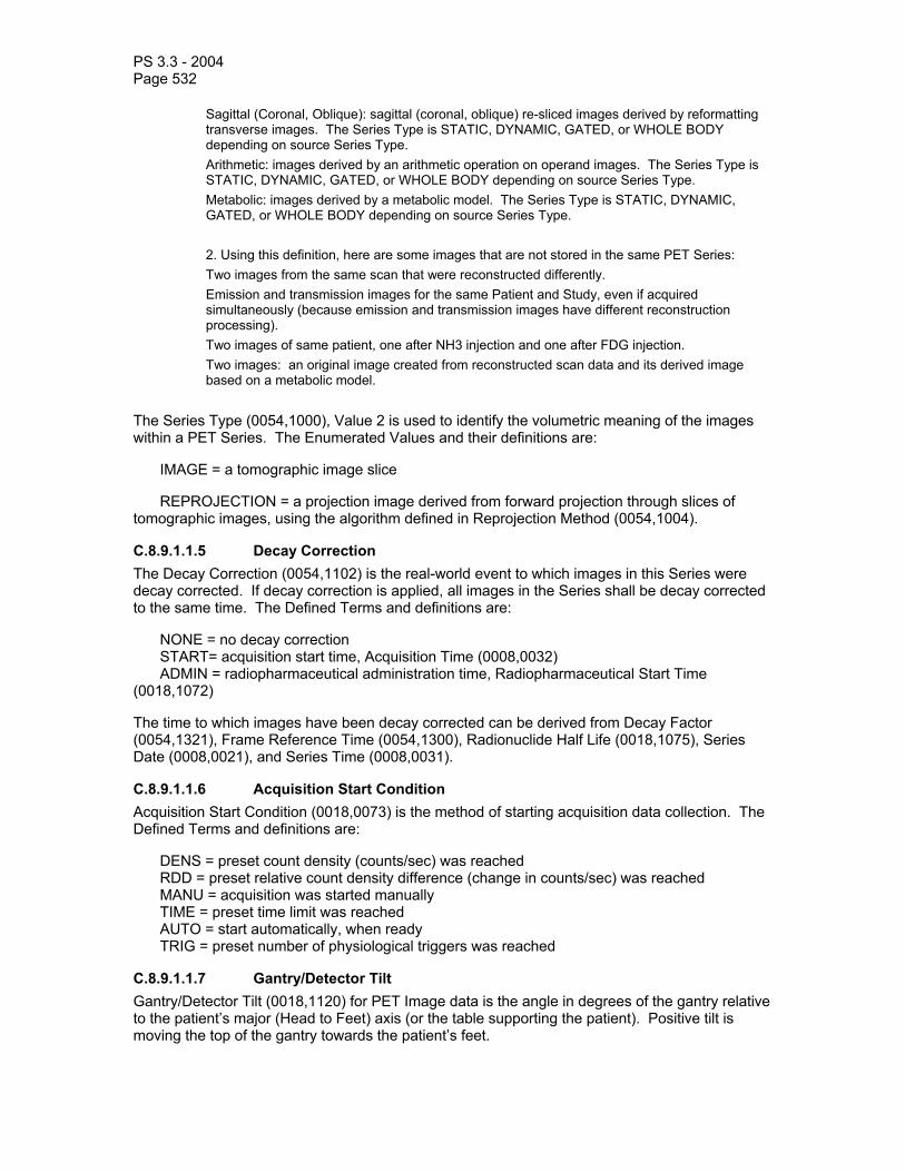
PS 3.3 - 2004 Page 532
Sagittal (Coronal, Oblique): sagittal (coronal, oblique) re-sliced images derived by reformatting transverse images. The Series Type is STATIC, DYNAMIC, GATED, or WHOLE BODY depending on source Series Type.
Arithmetic: images derived by an arithmetic operation on operand images. The Series Type is STATIC, DYNAMIC, GATED, or WHOLE BODY depending on source Series Type.
Metabolic: images derived by a metabolic model. The Series Type is STATIC, DYNAMIC, GATED, or WHOLE BODY depending on source Series Type.
2. Using this definition, here are some images that are not stored in the same PET Series: Two images from the same scan that were reconstructed differently. Emission and transmission images for the same Patient and Study, even if acquired
simultaneously (because emission and transmission images have different reconstruction processing).
Two images of same patient, one after NH3 injection and one after FDG injection. Two images: an original image created from reconstructed scan data and its derived image
based on a metabolic model.
The Series Type (0054,1000), Value 2 is used to identify the volumetric meaning of the images within a PET Series. The Enumerated Values and their definitions are:
IMAGE = a tomographic image slice
REPROJECTION = a projection image derived from forward projection through slices of tomographic images, using the algorithm defined in Reprojection Method (0054,1004).
C.8.9.1.1.5 Decay Correction The Decay Correction (0054,1102) is the real-world event to which images in this Series were decay corrected. If decay correction is applied, all images in the Series shall be decay corrected to the same time. The Defined Terms and definitions are:
NONE = no decay correction START= acquisition start time, Acquisition Time (0008,0032) ADMIN = radiopharmaceutical administration time, Radiopharmaceutical Start Time (0018,1072)
The time to which images have been decay corrected can be derived from Decay Factor (0054,1321), Frame Reference Time (0054,1300), Radionuclide Half Life (0018,1075), Series Date (0008,0021), and Series Time (0008,0031).
C.8.9.1.1.6 Acquisition Start Condition Acquisition Start Condition (0018,0073) is the method of starting acquisition data collection. The Defined Terms and definitions are:
DENS = preset count density (counts/sec) was reached RDD = preset relative count density difference (change in counts/sec) was reached MANU = acquisition was started manually TIME = preset time limit was reached AUTO = start automatically, when ready TRIG = preset number of physiological triggers was reached
C.8.9.1.1.7 Gantry/Detector Tilt Gantry/Detector Tilt (0018,1120) for PET Image data is the angle in degrees of the gantry relative to the patient’s major (Head to Feet) axis (or the table supporting the patient). Positive tilt is moving the top of the gantry towards the patient’s feet.

PS 3.3 - 2004 Page 533
C.8.9.1.1.8 Axial Mash Axial Mash (0054,1201) is multi-valued and is defined as the number of unique axial Lines of Response (LOR) that were mashed together (center of the axial field of view only). Value 1 is the number of LORs mashed for an odd slice. Value 2 is the number of LORs mashed for an even slice. For discrete crystal scanners, each unique LOR corresponds to a pair of crystals. For continuous detectors whose bin size is variable, the number of LORs mashed is determined by the actual bin size divided by the Detector Element Size (0054,1203), Value 2. The value of Axial Mash (0054,1201) is the same regardless of whether the mashing was done during acquisition or reconstruction.
Note: As an example on a discrete crystal scanner, if a ring difference of -2,0,+2 are binned as an odd slice and a ring difference of -1,+1 are binned as an even slice, then the Axial Mash (0054,1201) is equal to 3\2 .
C.8.9.1.1.9 Transverse Mash Transverse Mash (0054,1202) is defined as the number of unique transverse Lines of Response (LOR) that were mashed together. For discrete crystal scanners, each unique LOR corresponds to a pair of crystals. For continuous detectors whose bin size is variable, the number of LORs mashed is determined by the actual bin size divided by the Detector Element Size (0054,1203), Value 1. The value of Transverse Mash (0054,1202) is the same regardless of whether the mashing was done during acquisition or reconstruction.
C.8.9.1.1.10 Energy Window Range Sequence Multiple energy windows are allowed in order to allow coincidence events based on additional Energy Windows (e.g. Compton events scattered in the detector). All energy windows are assumed to contribute to all images in the PET Series.
C.8.9.1.1.11 Temporal Relationships of Images in PET Series The following diagram shows the temporal relationships of images within a PET Series.

PS 3.3 - 2004 Page 534
Injection Manual Start
Radiophar maceutical Start Time (0018,1072)
Series Time (0008,0031)
Acquisition Time
(0008,0032),first Time
Slice
Start of first Time Slice
Start of second
Time Slice
Acquisition Time
(0008,0032),second
Time Slice
Frame Reference Time (0054,1300),first Time
Slice
Frame Ref erence Time (0054,1300), second Time
Slice
Pause (no accumulation of counts)Acquiring counts
End ofacquisition
Time
Real World Event
PET Image Attribute
A time fixed to a real-world eventA time not related to a real-world
Example DYNAMIC PET Series
Legend:
Injection Manual Start
Radiophar maceutical Start Time (0018,1072)
Series Time (0008,0031)
Acquisition Time
(0008,0032),all Time
Slots
Start ofacquisition
Firsttrigger
Four Trigger Time
(0018,1060) values,for four
Time Slots Frame Reference Time (0054,1300), any Time
Slot
End ofacquisition
Time
Real World Event
PET Image Attribute
Example GATED PET Series
Secondtrigger
Actual Frame Duration (0018,1242), second
Time Slice
Actual Frame Duration
(0018,1242), first Time Slice
Actual Frame Duration (0018,1242), all Time Slots
Four Frame Time (0018,1063) values, for four Time Slots
Capable of acquiring
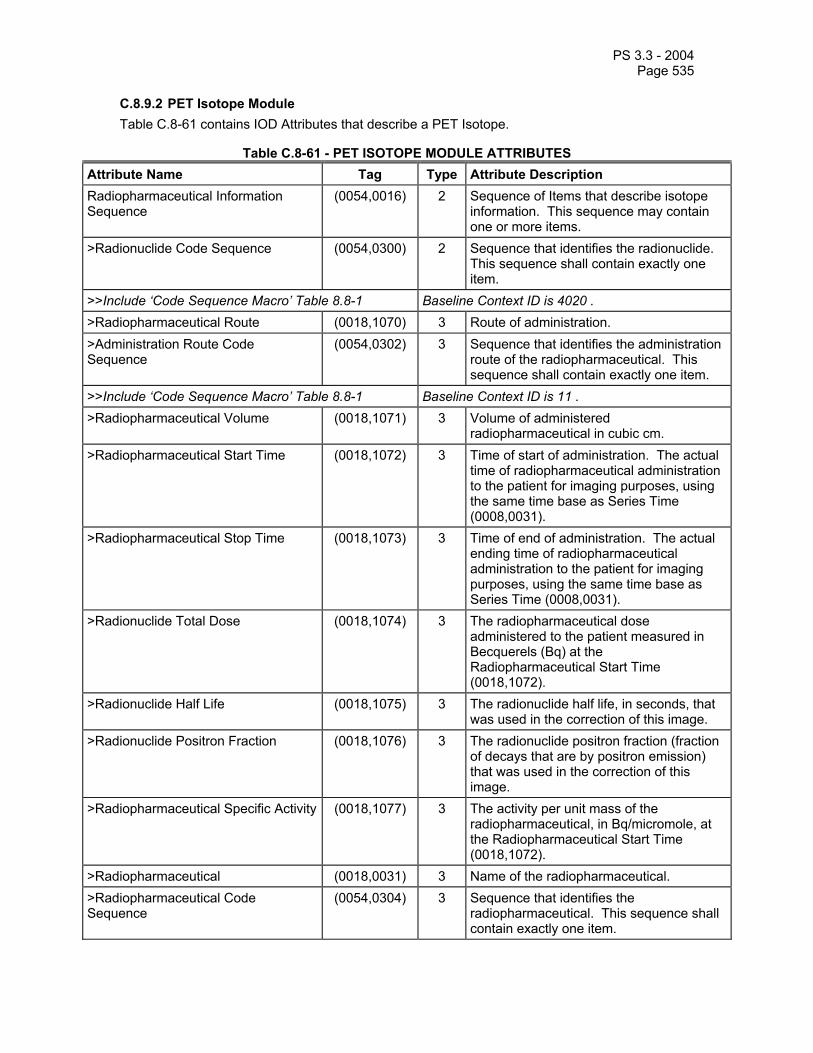
PS 3.3 - 2004 Page 535
C.8.9.2 PET Isotope Module Table C.8-61 contains IOD Attributes that describe a PET Isotope.
Table C.8-61 - PET ISOTOPE MODULE ATTRIBUTES Attribute Name Tag Type Attribute Description Radiopharmaceutical Information Sequence
(0054,0016) 2 Sequence of Items that describe isotope information. This sequence may contain one or more items.
>Radionuclide Code Sequence (0054,0300) 2 Sequence that identifies the radionuclide. This sequence shall contain exactly one item.
>>Include ‘Code Sequence Macro’ Table 8.8-1 Baseline Context ID is 4020 . >Radiopharmaceutical Route (0018,1070) 3 Route of administration. >Administration Route Code Sequence
(0054,0302) 3 Sequence that identifies the administration route of the radiopharmaceutical. This sequence shall contain exactly one item.
>>Include ‘Code Sequence Macro’ Table 8.8-1 Baseline Context ID is 11 . >Radiopharmaceutical Volume (0018,1071) 3 Volume of administered
radiopharmaceutical in cubic cm. >Radiopharmaceutical Start Time (0018,1072) 3 Time of start of administration. The actual
time of radiopharmaceutical administration to the patient for imaging purposes, using the same time base as Series Time (0008,0031).
>Radiopharmaceutical Stop Time (0018,1073) 3 Time of end of administration. The actual ending time of radiopharmaceutical administration to the patient for imaging purposes, using the same time base as Series Time (0008,0031).
>Radionuclide Total Dose (0018,1074) 3 The radiopharmaceutical dose administered to the patient measured in Becquerels (Bq) at the Radiopharmaceutical Start Time (0018,1072).
>Radionuclide Half Life (0018,1075) 3 The radionuclide half life, in seconds, that was used in the correction of this image.
>Radionuclide Positron Fraction (0018,1076) 3 The radionuclide positron fraction (fraction of decays that are by positron emission) that was used in the correction of this image.
>Radiopharmaceutical Specific Activity (0018,1077) 3 The activity per unit mass of the radiopharmaceutical, in Bq/micromole, at the Radiopharmaceutical Start Time (0018,1072).
>Radiopharmaceutical (0018,0031) 3 Name of the radiopharmaceutical. >Radiopharmaceutical Code Sequence
(0054,0304) 3 Sequence that identifies the radiopharmaceutical. This sequence shall contain exactly one item.
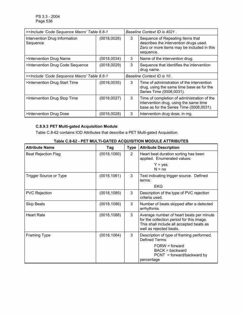
PS 3.3 - 2004 Page 536
>>Include ‘Code Sequence Macro’ Table 8.8-1 Baseline Context ID is 4021 . Intervention Drug Information Sequence
(0018,0026) 3 Sequence of Repeating Items that describes the intervention drugs used. Zero or more items may be included in this sequence.
>Intervention Drug Name (0018,0034) 3 Name of the intervention drug. >Intervention Drug Code Sequence (0018,0029) 3 Sequence that identifies the intervention
drug name. >>Include ‘Code Sequence Macro’ Table 8.8-1 Baseline Context ID is 10 . >Intervention Drug Start Time (0018,0035) 3 Time of administration of the intervention
drug, using the same time base as for the Series Time (0008,0031).
>Intervention Drug Stop Time (0018,0027) 3 Time of completion of administration of the intervention drug, using the same time base as for the Series Time (0008,0031).
>Intervention Drug Dose (0018,0028) 3 Intervention drug dose, in mg.
C.8.9.3 PET Multi-gated Acquisition Module Table C.8-62 contains IOD Attributes that describe a PET Multi-gated Acquisition.
Table C.8-62 - PET MULTI-GATED ACQUISITION MODULE ATTRIBUTES Attribute Name Tag Type Attribute Description Beat Rejection Flag (0018,1080) 2 Heart beat duration sorting has been
applied. Enumerated values: Y = yes N = no
Trigger Source or Type (0018,1061) 3 Text indicating trigger source. Defined terms: EKG
PVC Rejection (0018,1085) 3 Description of the type of PVC rejection criteria used.
Skip Beats (0018,1086) 3 Number of beats skipped after a detected arrhythmia.
Heart Rate (0018,1088) 3 Average number of heart beats per minute for the collection period for this image. This shall include all accepted beats as well as rejected beats.
Framing Type (0018,1064) 3 Description of type of framing performed. Defined Terms: FORW = forward BACK = backward PCNT = forward/backward by percentage
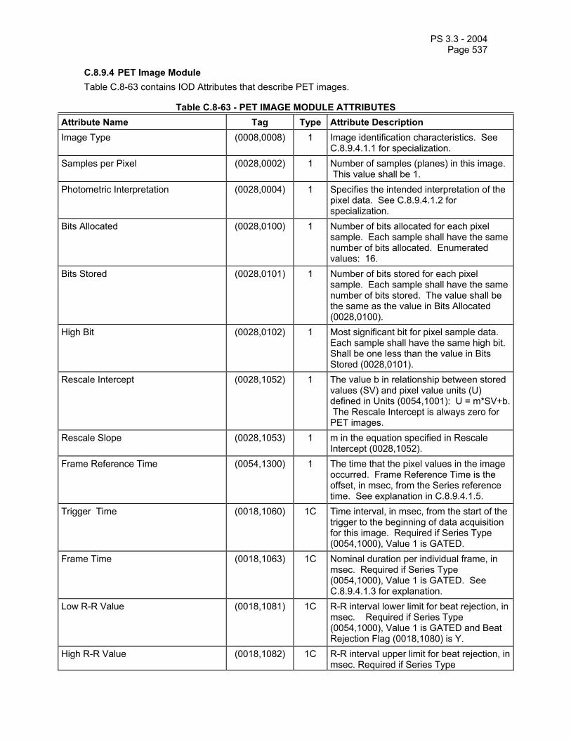
PS 3.3 - 2004 Page 537
C.8.9.4 PET Image Module Table C.8-63 contains IOD Attributes that describe PET images.
Table C.8-63 - PET IMAGE MODULE ATTRIBUTES Attribute Name Tag Type Attribute Description Image Type (0008,0008) 1 Image identification characteristics. See
C.8.9.4.1.1 for specialization. Samples per Pixel (0028,0002) 1 Number of samples (planes) in this image.
This value shall be 1. Photometric Interpretation (0028,0004) 1 Specifies the intended interpretation of the
pixel data. See C.8.9.4.1.2 for specialization.
Bits Allocated (0028,0100) 1 Number of bits allocated for each pixel sample. Each sample shall have the same number of bits allocated. Enumerated values: 16.
Bits Stored (0028,0101) 1 Number of bits stored for each pixel sample. Each sample shall have the same number of bits stored. The value shall be the same as the value in Bits Allocated (0028,0100).
High Bit (0028,0102) 1 Most significant bit for pixel sample data. Each sample shall have the same high bit.Shall be one less than the value in Bits Stored (0028,0101).
Rescale Intercept (0028,1052) 1 The value b in relationship between stored values (SV) and pixel value units (U) defined in Units (0054,1001): U = m*SV+b. The Rescale Intercept is always zero for PET images.
Rescale Slope (0028,1053) 1 m in the equation specified in Rescale Intercept (0028,1052).
Frame Reference Time (0054,1300) 1 The time that the pixel values in the image occurred. Frame Reference Time is the offset, in msec, from the Series reference time. See explanation in C.8.9.4.1.5.
Trigger Time (0018,1060) 1C Time interval, in msec, from the start of the trigger to the beginning of data acquisition for this image. Required if Series Type (0054,1000), Value 1 is GATED.
Frame Time (0018,1063) 1C Nominal duration per individual frame, in msec. Required if Series Type (0054,1000), Value 1 is GATED. See C.8.9.4.1.3 for explanation.
Low R-R Value (0018,1081) 1C R-R interval lower limit for beat rejection, in msec. Required if Series Type (0054,1000), Value 1 is GATED and Beat Rejection Flag (0018,1080) is Y.
High R-R Value (0018,1082) 1C R-R interval upper limit for beat rejection, in msec. Required if Series Type

PS 3.3 - 2004 Page 538
(0054,1000), Value 1 is GATED and Beat Rejection Flag (0018,1080) is Y.
Lossy Image Compression (0028,2110) 1C Specifies whether an Image has undergone lossy compression. Enumerated values: 00 = Image has NOT been subjected to lossy compression. 01 = Image has been subjected to lossy compression. See C.7.6.1.1.5. Required if Lossy Compression has been performed on the image.
Image Index (0054,1330) 1 An index identifying the position of this image within a PET Series. See C.8.9.4.1.9 for explanation.
Acquisition Date (0008,0022) 2 The date the acquisition of data that resulted in this image started. See C.8.9.4.1.4 for specialization.
Acquisition Time (0008,0032) 2 The time the acquisition of data that resulted in this image started. See C.8.9.4.1.4 for specialization.
Actual Frame Duration (0018,1242) 2 Elapsed time of the data acquisition for this image, in msec. See C.8.9.4.1.6 for explanation.
Nominal Interval (0018,1062) 3 Average duration of accepted beats, in msec, of the R-R interval.
Intervals Acquired (0018,1083) 3 Number of heartbeats that fall within Low R-R Value (0018,1081) and High R-R Value (0018,1082), and were therefore accepted and contribute coincidence events to this R-R Interval.
Intervals Rejected (0018,1084) 3 Number of heartbeats that fall outside Low R-R Value (0018,1081) and High R-R Value (0018,1082), and do not contribute coincidence events to this R-R Interval. However, they may contribute coincidence events to other R-R Intervals.
Primary (Prompts) Counts Accumulated
(0054,1310) 3 The sum of events that occur in the primary event channel. The counts include Trues +Scatter+ Randoms if Randoms Correction Method (0054,1100) is NONE; otherwise the counts are Trues +Scatter.
Secondary Counts Accumulated (0054,1311) 3 Sum of counts accumulated in secondary channels. See C.8.9.4.1.7 for explanation.
Slice Sensitivity Factor (0054,1320) 3 The slice-to-slice sensitivity correction factor that was used to correct this image. The value shall be one if no slice sensitivity correction was applied.
Decay Factor (0054,1321) 1C The decay factor that was used to scale

PS 3.3 - 2004 Page 539
this image. Required if Decay Correction (0054,1102) is other than NONE. If decay correction is applied, all images in the Series shall be decay corrected to the same time.
Dose Calibration Factor (0054,1322) 3 Factor that was used to scale this image from counts/sec to Bq/ml using a dose calibrator. The value shall be one if no dose calibration was applied. See C.8.9.4.1.8 for explanation.
Scatter Fraction Factor (0054,1323) 3 An estimate of the fraction of acquired counts that were due to scatter and were corrected in this image. The value shall be zero if no scatter correction was applied.
Dead Time Factor (0054,1324) 3 The average dead time correction factor that was applied to this image. The value shall be one if no dead time correction was applied.
Referenced Overlay Sequence (0008,1130) 3 A sequence which provides reference to a set of SOP Class/Instance pairs which are related independent Overlays. Uniquely identifies Overlays significantly related to this Image. Zero or more Items may be included in this sequence.
>Referenced SOP Class UID (0008,1150) 1C Uniquely identifies the referenced SOP Class. Required if Referenced Overlay Sequence (0008,1130) is sent.
>Referenced SOP Instance UID (0008,1155) 1C Uniquely identifies the referenced SOP Instance. Required if Referenced Overlay Sequence (0008,1130) is sent.
Referenced Curve Sequence (0008,1145) 3 A sequence which provides reference to a set of SOP Class/Instance pairs which are related independent Curves. Uniquely identifies Curves significantly related to this Image. Zero or more Items may be included in this sequence.
>Referenced SOP Class UID (0008,1150) 1C Uniquely identifies the referenced SOP Class. Required if Referenced Curve Sequence (0008,1145) is sent.
>Referenced SOP Instance UID (0008,1155) 1C Uniquely identifies the referenced SOP Instance. Required if Referenced Curve Sequence (0008,1145) is sent.
Include 'General Anatomy Optional Macro' Table 10-7 No Context ID for the Anatomic Region Sequence is defined.
Slice Progression Direction (0054,0500) 3 Describes the anatomical direction that slices are progressing as the slices are considered in order (as defined by the Slice Index. See section C.8.9.4.1.9 for a definition of Slice Index). Meaningful only for cardiac images. When View Code Sequence (0054,0220)

PS 3.3 - 2004 Page 540
indicates a short axis view, then Enumerated Values are: APEX_TO_BASE BASE_TO_APEX
View Code Sequence (0054,0220) 3 Sequence that describes the projection of the anatomic region of interest. Only a single Item shall be permitted in this sequence.
> Include ‘Code Sequence Macro’ Table 8.8-1 Baseline Context ID is 26. > View Modifier Code Sequence (0054,0222) 2C View Modifier.
Required if needed to fully specify the View. Only a single Item shall be permitted in this sequence.
>> Include ‘Code Sequence Macro’ Table 8.8-1 Baseline Context ID is 23.
C.8.9.4.1 PET Image Module Attribute Descriptions C.8.9.4.1.1 Image Type For PET Images, Image Type (0008,0008) is specified to be Type 1.
Note: For PET images, Image Type (0008,0008) Value 1 will be ORIGINAL for reconstructed images. DERIVED may be appropriate for some other results images. For PET images, Image Type (0008,0008) Value 2 will be PRIMARY.
C.8.9.4.1.2 Photometric Interpretation For PET images, Photometric Interpretation (0028,0004) shall have one of the following Enumerated Values:
MONOCHROME2
See C.7.6.3.1.2 for definition of this term.
C.8.9.4.1.3 Frame Time The Frame Time (0018,1063) is the explicit duration of the gated frame when Framing Type (0018,1064) is equal to FORW or BACK. Frame Time (0018,1063) is the nominal duration of the gated frame when Framing Type (0018,1064) is equal to PCNT.
C.8.9.4.1.4 Acquisition Date, Acquisition Time For PET Images, Acquisition Date (0008,0022) and Acquisition Time (0008,0032) are specified to be Type 2. The Acquisition Date (0008,0022) and Acquisition Time (0008,0032) use the same time base as Series Time (0008,0031).
For Series Type (0054,1000) Value 1 equal to STATIC, WHOLE BODY, or DYNAMIC, the Acquisition Time (0008,0032) is the real-world beginning of the accumulation of events into this Image. For STATIC, WHOLE BODY, or DYNAMIC Series, the Acquisition Time (0008,0032) may vary from Image to Image within a PET Series.
For Series Type (0054,1000) Value 1 equal to GATED, the Acquisition Time (0008,0032) is the real-world beginning of the capability of accumulating events into this Image. (The actual accumulation of events has only occurred during an R-R Interval.) For GATED Series, the Acquisition Time (0008,0032) shall not vary from Image to Image within a PET Series.

PS 3.3 - 2004 Page 541
C.8.9.4.1.5 Frame Reference Time Frame Reference Time (0054,1300) is the time that the pixel values in the Image occurred. Frame Reference Time is defined as the time offset, in msec, from the Series Reference Time, where the Series Reference Time is defined by the combination of Series Date (0008,0021) and Series Time (0008,0031).
Note: Frame Reference Time (0054,1300) is implementation dependent and may or may not be tied to any real-world event. To illustrate the meaning of Frame Reference Time (0054,1300), the following are some examples of possible implementations:
Example 1: For a long-lived radionuclide and a non-time-varying radiopharmaceutical distribution, an implementation sets the Frame Reference Time (0054,1300) to the midpoint of the Actual Frame Duration (0018,1242).
Example 2: For a short-lived radionuclide and a non-time-varying radiopharmaceutical distribution, an implementation sets the Frame Reference Time (0054,1300) to the time at which the average activity occurs for a decaying radionuclide, Tave . If image acquisition started at the Series Reference Time and the image has not been decay corrected, then Tave will be:
Tave=1λ ln
λ T1-e- λ T
where: lambda = decay constant = (ln 2)/T1/2
T1/2 = Radionuclide Half Life (0018,1075) T = Actual Frame Duration (0018,1242) Note that Tave will be sooner than the midpoint of the Actual Frame Duration (0018,1242).
Example 3: For a short-lived radionuclide and a time-varying radiopharmaceutical distribution,
an implementation with supplementary data (e.g. scanner count rates or blood sample data) sets the Frame Reference Time (0054,1300) to a derived time determined to be its best estimate of the time that the pixel values occurred.
C.8.9.4.1.6 Actual Frame Duration The accumulation of counts for a PET Image shall occur entirely between:
(1) the acquisition starting time (as specified by Acquisition Date (0008,0022) and Acquisition Time (0008,0032)), and
(2) the acquisition ending time, which is equal to the acquisition starting time in (1) plus the Actual Frame Duration (0018,1242).
If the Series Type (0054,1000), Value 1 is GATED, then the actual accumulation of counts has only occurred during an R-R Interval.
C.8.9.4.1.7 Secondary Counts Accumulated Secondary Counts Accumulated (0054,1311) is multi-valued and, if supplied, has Values corresponding to the Secondary Counts Type (0054,1220). The number and order of the Values in Secondary Counts Accumulated (0054,1311) shall be the same as Secondary Counts Type (0054,1220).
C.8.9.4.1.8 Dose Calibration Factor The Dose Calibration Factor (0054,1322) is the factor that was used to scale this image from counts/sec to Bq/ml using an external dose calibrator. The value shall be one if no dose calibration was applied. The application of a dose calibration correction is specified by Corrected Image (0028,0051) equal to DCAL.

PS 3.3 - 2004 Page 542
Note: Dose Calibration Factor (0054,1322) is not equal to the inverse of the sensitivity (kcps/Bq/ml) of the scanner, which is usually measured for a given radiopharmaceutical distribution and excluding the effects of attenuation.
C.8.9.4.1.9 Image Index Image Index (0054,1330) is an index identifying the position of this image within a PET Series.
Note: The scheme for encoding Image Index (0054,1330) is as follows. Images within a PET Series can be viewed as a multi-dimensional array whose possible dimensions include R-R Intervals, Time Slots, Time Slices, and Slices. The dimensions of the array are defined by the Series Type (0054,1000) Value 1. Each dimension of the array has an index that identifies the position of this image in the array. The indices are: R-R Interval Index, Time Slot Index, Time Slice Index, Slice Index. The indices are calculated as follows:
Index Range of Index Order of Images along that Dimension R-R Interval Index
1 to Number of R-R Intervals (0054,0061)
Increasing Low R-R Value (0018,1081)
Time Slot Index
1 to Number of Time Slots (0054,0071)
Increasing Trigger Time (0018,1060)
Time Slice Index
1 to Number of Time Slices (0054,0101)
Increasing Frame Reference Time (0054,1300)
Slice Index 1 to Number of Slices (0054,0081)
If Series Type (0054,1000) Value 2 is IMAGE: Order is in increasing position along the normal, where the normal is determined by the cross product of the direction cosines of the row and column of the image. See Image Orientation (0020,0037) in the Image Plane Module. If Series Type (0054,1000) Value 2 is REPROJECTION: Order is in increasing or decreasing angle of the normal, where the normal is determined by the cross product of the direction cosines of the row and column of the image. See Image Orientation (0020,0037) in the Image Plane Module. (Note that reprojection images rotate about only a single axis as described in C.8.9.1.1.1. Therefore, all normals are co-planar and make a single angle with respect to each other.)
Using these index values the position of this image within the multi-dimensional array (the Image Index (0054,1330)) is calculated as follows:
Series Type (0054,1000),
Value 1
Dimensions of Array (Last dimension is
most rapidly changing)
Encoding of Image Index (0054,1330)
STATIC Slice Slice Index WHOLE BODY Slice Slice Index DYNAMIC Time Slice \
Slice ( ( Time Slice Index - 1 ) * ( Number of Slices (0054,0081) ) )

PS 3.3 - 2004 Page 543
+ Slice Index GATED R-R Interval \
Time Slot \ Slice
( ( R-R Interval Index - 1 ) * ( Number of Time Slots (0054,0071) ) * ( Number of Slices (0054,0081) ) ) + ( ( Time Slot Index - 1 ) * ( Number of Slices (0054,0081) ) ) + Slice Index
C.8.9.5 PET Curve Module Table C.8-64 contains IOD Attributes that describe a PET Curve.
Table C.8-64 - PET CURVE MODULE ATTRIBUTES Attribute Name Tag Type Attribute Description Curve Dimensions (50xx,0005) 1 Number of dimensions for these data. The
dimensions may be any number from 1 to n. See C.8.9.5.1.2 for specialization.
Type of Data (50xx,0020) 1 Type of data in this curve. See C.8.9.5.1.3 for specialization of Defined Terms.
Curve Data (50xx,3000) 1 Curve data. See C.10.2.1.4 and C.8.9.5.1.4 for further explanation.
Axis Units (50xx,0030) 1 Units of measure for the axes. See C.8.9.5.1.5 for specialization of Defined Terms.
Dead Time Correction Flag (0054,1401) 1C Dead time correction has been applied to Curve Data (50xx,3000). Required if Type of Data (50xx,0020) is BLDSMPL. Enumerated Values: Y = yes N = no
Counts Included (0054,1400) 2C Type of counts included in this count rate data. Enumerated Values: TRUES SCATTER RANDOMS SINGLES Required if Axis Units (50xx,0030) contains CPS or CNTS.
Processing Function (0018,5020) 3 A textual description of the processing that has been applied to this curve. (e.g. smoothing, time interpolation)
C.8.9.5.1 PET Curve Attribute Descriptions C.8.9.5.1.1 Specialization of Curve Module Attributes For PET Curves, all Curve Data (50xx,3000) values that are temporal are defined as time offsets from the Series Reference Time, where the Series Reference Time is defined by the combination of Series Date (0008,0021) and Series Time (0008,0031).
Note: Because the PET Curve is related to a single PET Series, all Curve Data (50xx,3000) points must be decay corrected (or not) to the same real-world event as defined in Decay Correction

PS 3.3 - 2004 Page 544
(0054,1102).
C.8.9.5.1.2 Curve Dimensions If the Type of Data (50xx,0020) is SYSRATE, then the Curve Dimensions (50xx,0005) shall equal 2.
If the Type of Data (50xx,0020) is SLICERATE, then the Curve Dimensions (50xx,0005) shall equal 3.
If the Type of Data (50xx,0020) is BLDSMPL, then the Curve Dimensions (50xx,0005) shall equal 2.
If the Type of Data (50xx,0020) is CPM, then the Curve Dimensions (50xx,0005) shall equal 3.
C.8.9.5.1.3 Type of Data A description of the Type of Data (50xx,0020) in this Curve. Defined Terms:
SYSRATE = system count rate SLICERATE = slice count rate BLDSMPL = blood samples CPM = cardiac polar map
Note: Cardiac Polar Maps will be supported under the Standalone PET Curve IOD. This does not preclude the transmission of Cardiac Polar Maps in Secondary Capture images when preservation of quantitative information is not required.
C.8.9.5.1.4 Curve Data If Type of Data (50xx,0020) is SYSRATE, then Curve Data (50xx,3000) is specified as x1\y1\x2\y2\... where:
xn = time since Series Date (0008,0021) and Series Time (0008,0031) yn = system count rate at time xn.
If Type of Data (50xx,0020) is SLICERATE, then Curve Data (50xx,3000) is specified as x1\y1\z1\x2\y2\z2\... where:
xn = time since Series Date (0008,0021) and Series Time (0008,0031) yn = position of slice zn = slice count rate of slice yn at time xn
Values of yn shall be increasing from patient inferior to superior.
If Type of Data (50xx,0020) is BLDSMPL, then Curve Data (50xx,3000) is specified as x1\y1\x2\y2\... where:
xn = time since Series Date (0008,0021) and Series Time (0008,0031) yn = blood activity at time xn.
If the Type of Data (50xx,0020) is BLDSMPL, then Axis Units (50xx,0030) Value 1 shall be MILS or SEC, and Axis Units (50xx,0030) Value 2 shall be BQML or CPS.
If Type of Data (50xx,0020) is CPM, then Curve Data (50xx,3000) is specified as x1\y1\z1\x2\y2\z2\... where:
xn = distance from apex along long axis of heart yn = start angle of sector zn = value for sector in appropriate units.

PS 3.3 - 2004 Page 545
Sector boundaries (yn) are measured in degrees clockwise relative to the antero-lateral wall. The end angle for a sector is the start angle of next largest yn value for the same xn. The end angle for the last sector is the start angle of the smallest yn for the same xn.
C.8.9.5.1.5 Axis Units Axis Units (50xx,0030) are the units of measure for the axes. One value for each dimension. The order for the units is the same as the dimensions for the curve data in Curve Data (50xx,3000).
Defined Terms:
SEC = seconds CNTS = counts MM = millimeters NONE = unitless CM = centimeters CM2 = cm**2 DEG = degrees MILS = milliseconds PCNT = percent CPS = counts/second BQML = Becquerels/milliliter MGMINML = milligram/minute/milliliter UMOLMINML = micromole/minute/milliliter MLMING = milliliter/minute/gram MLG = milliliter/gram 1CM = 1/centimeter UMOLML = micromole/milliliter PROPCNTS = proportional to counts PROPCPS = proportional to counts/sec MLMINML = milliliter/minute/milliliter MLML = milliliter/milliliter GML = grams/milliliter STDDEV = standard deviations
If the Type of Data (50xx,0020) is SYSRATE, then Axis Units (50xx,0030) Value 1 shall be MILS or SEC, and Axis Units (50xx,0030) Value 2 shall be CPS.
If the Type of Data (50xx,0020) is SLICERATE, then Axis Units (50xx,0030) Value 1 shall be MILS or SEC, Axis Units (50xx,0030) Value 2 shall be MM or CM, and Axis Units (50xx,0030) Value 3 shall be CPS. Values of Axis Units (50xx,0030) Value 2 shall be increasing from patient inferior to superior.
If the Type of Data (50xx,0020) is BLDSMPL, then Axis Units (50xx,0030) Value 1 shall be MILS or SEC, and Axis Units (50xx,0030) Value 2 shall be BQML or CPS.
If the Type of Data (50xx,0020) is CPM, then Axis Units (50xx,0030) Value 1 shall be MM or CM, Axis Units (50xx,0030) Value 2 shall be DEG, and Axis Units (50xx,0030) Value 3 shall be one of:
CNTS, NONE, CM2, PCNT, CPS, BQML, MGMINML, UMOLMINML, MLMING, MLG, 1CM, UMOLML, PROPCNTS, PROPCPS, MLMINML, MLML, GML, STDDEV

PS 3.3 - 2004 Page 546
C.8.10 Hardcopy Modules C.8.10.1 Hardcopy Equipment Module This Module describes equipment used to create Hardcopy Grayscale and Color Image IODs.
Table C.8-65 HARDCOPY EQUIPMENT MODULE ATTRIBUTES
Attribute Name Tag Type Attribute Description Modality (0008,0060) 1 Type of equipment that created this Hardcopy
Image. Enumerated Value: HC
Hardcopy Creation Device ID (0018,1011) 3 User defined identification of the device that created this Hardcopy Image.
Hardcopy Device Manufacturer
(0018,1017) 3 Manufacturer of the device that created this Hardcopy Image.
Hardcopy Device Software Versions
(0018,101A) 3 Manufacturer's designation of the software of the device that created this Hardcopy Image.
Hardcopy Device Manufacturer's Model Name
(0018,101B) 3 Manufacturer's model number of the device that created this Hardcopy Image.
Note: The Attributes specified in the General Equipment Module (See Table C.7-6) describe the
equipment which created the image that was the source for this Hardcopy Image. The Attributes of the Hardcopy Equipment Module define the equipment that created the Hardcopy Image.
C.8.10.2 Hardcopy Grayscale Image Module This Module describes a printable 8 or 12 bit grayscale image. The Hardcopy Grayscale Image Pixel Module is a specialization of the Image Pixel Module defined in C.7.6.3 of this part.
Table C.8-66 HARDCOPY GRAYSCALE IMAGE MODULE ATTRIBUTES
Attribute Name Tag Type Attribute Description Samples Per Pixel (0028,0002) 1 See C.7.6.3 for description of Image Pixel Module;
Enumerated Value: 1 Photometric Interpretation (0028,0004) 1 See C.7.6.3 for description of Image Pixel Module;
Enumerated Values: MONOCHROME1 MONOCHROME2
Rows (0028,0010) 1 See C.7.6.3 for description of Image Pixel Module. Columns (0028,0011) 1 See C.7.6.3 for description of Image Pixel Module. Pixel Aspect Ratio (0028,0034) 1C See C.7.6.3 for description of Image Pixel Module.
Required if the aspect ratio is not 1\1. Bits Allocated (0028,0100) 1 See C.7.6.3 for description of Image Pixel Module.
Enumerated Values: 8 (if Bits Stored = 8) 16 (if Bits Stored =12)
Bits Stored (0028,0101) 1 See C.7.6.3 for description of Image Pixel Module. Enumerated Values:

PS 3.3 - 2004 Page 547
8, 12 High Bit (0028,0102) 1 See C.7.6.3 for description of Image Pixel Module.
The value shall be Bits Stored (0028,0101) - 1. Pixel Representation (0028,0103) 1 See C.7.6.3 for description of Image Pixel Module.
Enumerated Value: 0000H (unsigned integer)
Pixel Data (7FE0,0010) 1 See C.7.6.3 for description of Image Pixel Module.
C.8.10.3 Hardcopy Color Image Module This Module describes a printable 8 bit RGB Color image. The Hardcopy Color Image Pixel Module is a specialization of the Image Pixel Module defined in C.7.6.3 of this part.
Table C.8-67 HARDCOPY COLOR IMAGE MODULE ATTRIBUTES
Attribute Name Tag Type Attribute Description Samples Per Pixel (0028,0002) 1 See C.7.6.3 for description of Image Pixel Module;
Enumerated Value: 3
Photometric Interpretation (0028,0004) 1 See C.7.6.3 for description of Image Pixel Module; Enumerated Value: RGB
Planar Configuration (0028,0006) 1 See C.7.6.3 for description of Image Pixel Module; Enumerated Value: 0001H (frame interleave)
Rows (0028,0010) 1 See C.7.6.3 for description of Image Pixel Module. Columns (0028,0011) 1 See C.7.6.3 for description of Image Pixel Module. Pixel Aspect Ratio (0028,0034) 1C See C.7.6.3 for description of Image Pixel Module.
Required if the aspect ratio is not 1\1. Bits Allocated (0028,0100) 1 See C.7.6.3 for description of Image Pixel Module;
Enumerated Value: 8
Bits Stored (0028,0101) 1 See C.7.6.3 for description of Image Pixel Module; Enumerated Value: 8
High Bit (0028,0102) 1 See C.7.6.3 for description of Image Pixel Module; Enumerated Value: 7
Pixel Representation (0028,0103) 1 See C.7.6.3 for description of Image Pixel Module; Enumerated Value: 0000H (unsigned integer)
Pixel Data (7FE0,0010) 1 See C.7.6.3 for description of Image Pixel Module
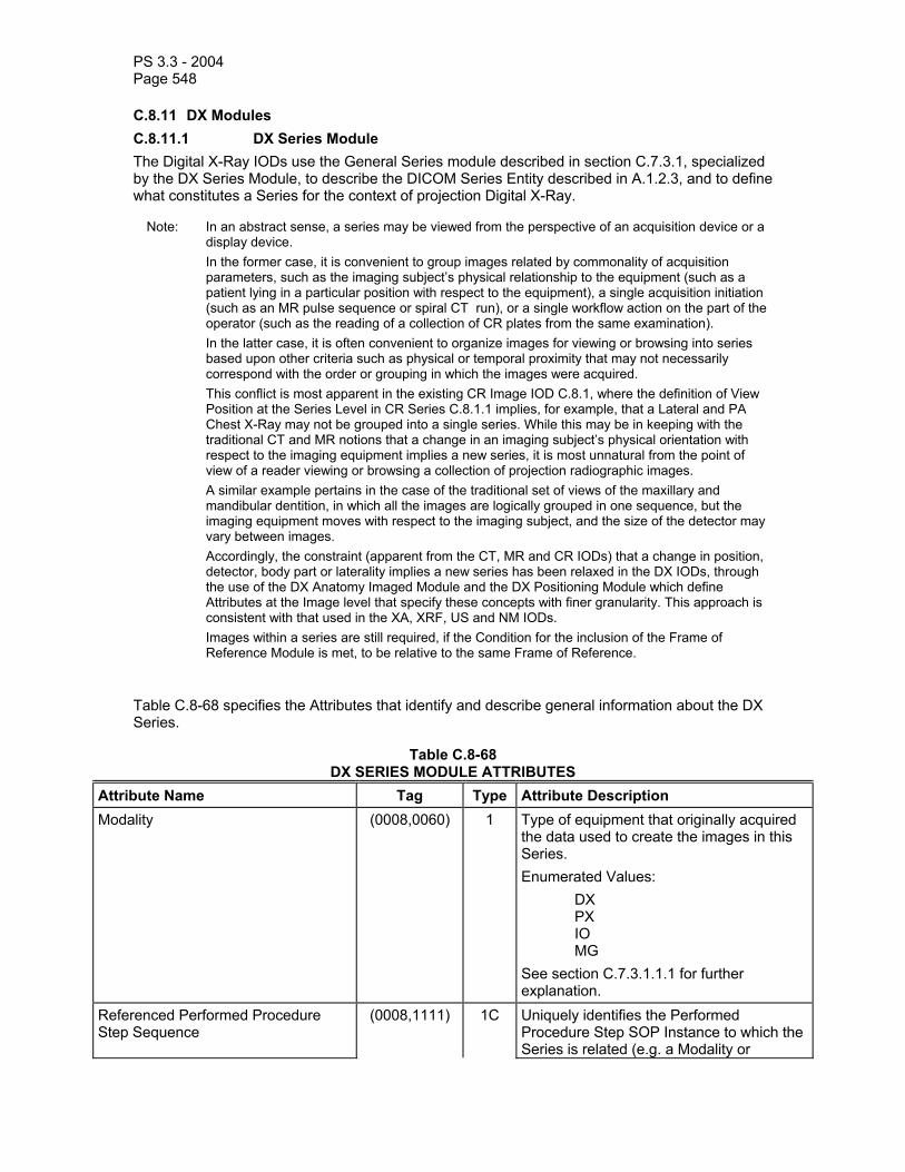
PS 3.3 - 2004 Page 548
C.8.11 DX Modules C.8.11.1 DX Series Module The Digital X-Ray IODs use the General Series module described in section C.7.3.1, specialized by the DX Series Module, to describe the DICOM Series Entity described in A.1.2.3, and to define what constitutes a Series for the context of projection Digital X-Ray.
Note: In an abstract sense, a series may be viewed from the perspective of an acquisition device or a display device.
In the former case, it is convenient to group images related by commonality of acquisition parameters, such as the imaging subject’s physical relationship to the equipment (such as a patient lying in a particular position with respect to the equipment), a single acquisition initiation (such as an MR pulse sequence or spiral CT run), or a single workflow action on the part of the operator (such as the reading of a collection of CR plates from the same examination).
In the latter case, it is often convenient to organize images for viewing or browsing into series based upon other criteria such as physical or temporal proximity that may not necessarily correspond with the order or grouping in which the images were acquired.
This conflict is most apparent in the existing CR Image IOD C.8.1, where the definition of View Position at the Series Level in CR Series C.8.1.1 implies, for example, that a Lateral and PA Chest X-Ray may not be grouped into a single series. While this may be in keeping with the traditional CT and MR notions that a change in an imaging subject’s physical orientation with respect to the imaging equipment implies a new series, it is most unnatural from the point of view of a reader viewing or browsing a collection of projection radiographic images.
A similar example pertains in the case of the traditional set of views of the maxillary and mandibular dentition, in which all the images are logically grouped in one sequence, but the imaging equipment moves with respect to the imaging subject, and the size of the detector may vary between images.
Accordingly, the constraint (apparent from the CT, MR and CR IODs) that a change in position, detector, body part or laterality implies a new series has been relaxed in the DX IODs, through the use of the DX Anatomy Imaged Module and the DX Positioning Module which define Attributes at the Image level that specify these concepts with finer granularity. This approach is consistent with that used in the XA, XRF, US and NM IODs.
Images within a series are still required, if the Condition for the inclusion of the Frame of Reference Module is met, to be relative to the same Frame of Reference.
Table C.8-68 specifies the Attributes that identify and describe general information about the DX Series.
Table C.8-68 DX SERIES MODULE ATTRIBUTES
Attribute Name Tag Type Attribute Description Modality (0008,0060) 1 Type of equipment that originally acquired
the data used to create the images in this Series. Enumerated Values: DX PX IO MG See section C.7.3.1.1.1 for further explanation.
Referenced Performed Procedure Step Sequence
(0008,1111) 1C Uniquely identifies the Performed Procedure Step SOP Instance to which the Series is related (e.g. a Modality or

PS 3.3 - 2004 Page 549
General-Purpose Performed Procedure Step SOP Instance or Study Component SOP Instance). The Sequence shall have one Item. Required if the Modality Performed Procedure Step SOP Class, General Purpose Performed Procedure Step SOP Class or Study Component SOP Class is supported.
>Referenced SOP Class UID (0008,1150) 1C Uniquely identifies the referenced SOP Class. Required if Referenced Performed Procedure Step Sequence (0008,1111) is sent.
>Referenced SOP Instance UID (0008,1155) 1C Uniquely identifies the referenced SOP Instance. Required if Referenced Performed Procedure Step Sequence (0008,1111) is sent.
Presentation Intent Type (0008,0068) 1 Identifies the intent of the images that are contained within this Series. Enumerated Values: FOR PRESENTATION FOR PROCESSING See C.8.11.1.1.1 for further explanation.
C.8.11.1.1 DX Series Attribute Descriptions C.8.11.1.1.1 Presentation Intent Type Presentation Intent Type (0008,0068) shall identify the intent for the purposes of display or other presentation of all Images within this Series.
Notes: 1. Since this is a Series level attribute, all Images within a Series have the same value for this Attribute.
2. The intent of this restriction is to ensure that FOR PRESENTATION and FOR PROCESSING images are placed in separate Series, so that no confusion can arise as to which images are suitable for diagnostic reading as determined by local policy.
A Series of Images intended for viewing by an observer, after application of any grayscale transformations specified in the image object such as VOI LUT, shall have an Enumerated Value of FOR PRESENTATION.
Notes: 1. These images may still be of Image Type (0008,0008) ORIGINAL rather than DERIVED despite the possibility that they may have undergone some processing, such as unsharp masking. In this case a DERIVED image would have undergone yet further processing to make it substantially different from the original. See Figure C.8-13.
2. These images may still be subjected to processing or further processing, if appropriate, depending on the application.
3. These images are intended for display on a device, without (further) processing, since that device may not be capable of image processing. The quality of the displayed image or its suitability for any purpose is beyond the scope of the DICOM Standard.

PS 3.3 - 2004 Page 550
Images that have been corrected to account for characteristics of the detector but which are intended to be further processed before being displayed, shall have an Enumerated Value of FOR PROCESSING.
Note: This type is provided to allow the functions of image acquisition and image processing for presentation to be separated and yet have images conveyed between the two processes using a DICOM object. Individual sites or users may choose to substitute their own specialized processing in place of that supplied by the implementor.
Images available at this stage of processing may be useful for quality control and problem solving purposes, as well as academic research.
Images of this type may also be archived, retrieved and processed with different algorithms or parameters in order to alter the appearance of specific features for clinical purposes.
The nature of the detector correction that may have been applied before sending an image of type FOR PROCESSING is not specified. In particular, acquisitions that acquire several sets of matrices of pixel values (such as image data, gain offset and a defect map) must perform some processing (detector correction) before a DX Image object can be instantiated.
The nature of the processing that may have been applied before sending an image of type FOR PRESENTATION is also not specified.
It is expected that individual implementors will use Private Attributes to convey specifics of the processing applied that may be of use for further processing by those aware of the parameters and algorithms. The diversity of detector types and processing algorithms make it undesirable to standardize such parameters.
If images from the same exposure exist with different Values of Presentation Intent Type (0008,0068), then they shall have different SOP Instance UIDs.
Notes: 1. Source Image Sequence (0008,2112) may be used to relate these images. 2. The SOP Class UIDs of the two images will also be different.

PS 3.3 - 2004 Page 551
Detector DataDetector
Corrected Data
ORIGINAL -
FOR PROCESSING
Detector Correction
Processing for Presentation
Advanced Processing, eg. morphological operations
Viewed on Workstation
(with VOI LUT)From exposure(s)
Defect map, baseline
correction, etc.
DERIVED
ORIGINAL -
FOR PRESENTATION
Figure C.8-13 - Explanation of Presentation Intent Type
C.8.11.2 DX Anatomy Imaged Module Table C.8-69 contains IOD Attributes that describe the anatomy contained in a DX IOD.
Table C.8-69 DX ANATOMY IMAGED MODULE ATTRIBUTES
Attribute Name Tag Type Attribute Description Image Laterality (0020,0062) 1 Laterality of (possibly paired) body part (as
described in Anatomic Region Sequence (0008,2218)) examined. Enumerated Values: R = right L = left U = unpaired B = both left and right
Note: This Attribute is mandatory, in order to ensure that images may be positioned correctly relative to one another for display.
Shall be consistent with any laterality information contained in Primary Anatomic Structure Modifier Sequence (0008,2230), if present.
Note: Laterality (0020,0060) is a Series level Attribute and must be the same for all Images in the Series, hence it must be absent.
Include 'General Anatomy Required Macro' Table 10-6 Defined Context ID for the Anatomic Region Sequence is 4009. This is the anatomic region that is placed on the table

PS 3.3 - 2004 Page 552
or bucky for examination. Note: It is strongly recommended that
Anatomic Region Sequence (0008,2218) be sent with a value, in order to ensure that images may be positioned correctly relative to one another for display.
C.8.11.2.1 DX Anatomy Imaged Attribute Descriptions The Attributes in this Module extend the function of Body Part Examined (0018,0015) as used in other IODs, and are intended to be used to facilitate the management of images and series in terms of routing, storage and display, as well as to dictate certain Conditions on Attributes and Modules in the DX IOD.
C.8.11.3 DX Image Module Table C.8-70 contains IOD Attributes that describe a DX Image by specializing Attributes of the General Image and Image Pixel Modules, and adding additional Attributes.
Table C.8-70 DX IMAGE MODULE ATTRIBUTES
Attribute Name Tag Type Attribute Description Image Type (0008,0008) 1 Image identification characteristics.
See C.8.11.3.1.1 for specialization. Samples per Pixel (0028,0002) 1 Number of samples in this image. Shall
have an Enumerated Value of 1. Photometric Interpretation (0028,0004) 1 Specifies the intended interpretation of the
pixel data. Enumerated Values: MONOCHROME1 MONOCHROME2
Bits Allocated (0028,0100) 1 Number of bits allocated for each pixel sample. Enumerated Values: 8, 16
Bits Stored (0028,0101) 1 Number of bits stored for each pixel sample. Enumerated Values: 6 to 16
High Bit (0028,0102) 1 Most significant bit for pixel sample data. Shall have an Enumerated Value of one less than the value in Bit Stored (0028,0101).
Pixel Representation (0028,0103) 1 Data representation of the pixel samples. Shall have the Enumerated Value:
0000H = Unsigned Integer.
Pixel Intensity Relationship (0028,1040) 1 The relationship between the Pixel sample values and the X-Ray beam intensity. Enumerated Values: LIN = Linearly proportional to X-Ray beam intensity

PS 3.3 - 2004 Page 553
LOG = Logarithmically proportional to X-Ray beam intensity See C.8.11.3.1.2 for further explanation.
Pixel Intensity Relationship Sign (0028,1041) 1 The sign of the relationship between the Pixel sample values stored in Pixel Data (7FE0,0010) and the X-Ray beam intensity.Enumerated Values; 1 = Lower pixel values correspond to less X-Ray beam intensity -1 = Higher pixel values correspond to less X-Ray beam intensity See C.8.11.3.1.2 for further explanation.
Rescale Intercept (0028,1052) 1 The value b in the relationship between stored values (SV) in Pixel Data (7FE0,0010) and the output units specified in Rescale Type (0028,1054). Output units = m*SV + b. Enumerated Value: 0 See C.8.11.3.1.2 for further explanation.
Rescale Slope (0028,1053) 1 m in the equation specified by Rescale Intercept (0028,1052). Enumerated Value: 1 See C.8.11.3.1.2 for further explanation.
Rescale Type (0028,1054) 1 Specifies the output units of Rescale Slope (0028,1053) and Rescale Intercept (0028,1052). Enumerated Value: US = Unspecified See C.8.11.3.1.2 for further explanation.
Presentation LUT Shape (2050,0020) 1 Specifies an identity transformation for the Presentation LUT, other than to account for the value of Photometric Interpretation (0028,0004), such that the output of all grayscale transformations defined in the IOD containing this Module are defined to be P-Values. Enumerated Values: IDENTITY - output is in P-Values - shall be used if Photometric Interpretation (0028,0004) is MONOCHROME2. INVERSE - output after inversion is in P-Values - shall be used if Photometric Interpretation (0028,0004) is MONOCHROME1. See C.8.11.3.1.2 for further explanation.
Lossy Image Compression (0028,2110) 1 Specifies whether an Image has undergone lossy compression. Enumerated Values:
00 = Image has NOT been subjected

PS 3.3 - 2004 Page 554
to lossy compression. 01 = Image has been subjected to
lossy compression. See C.7.6.1.1.5 for further explanation.
Lossy Image Compression Ratio (0028,2112) 1C See C.7.6.1.1.5 for further explanation. Required if Lossy Compression has been performed on the Image.
Derivation Description (0008,2111) 3 A text description of how this image was derived. See C.8.11.3.1.4 for further explanation.
Acquisition Device Processing Description
(0018,1400) 3 Indicates any visual processing performed on the images prior to exchange. See C.8.11.3.1.3 for further explanation.
Acquisition Device Processing Code (0018,1401) 3 Code representing the device-specific processing associated with the image (e.g. Organ Filtering code)
Note: This Code is manufacturer specific but provides useful annotation information to the knowledgeable observer.
Patient Orientation (0020,0020) 1 Patient direction of the rows and columns of the image. See C.7.6.1.1.1 for further explanation.
Calibration Image (0050,0004) 3 Indicates whether a reference object (phantom) of known size is present in the image and was used for calibration. Enumerated Values: YES NO Device is identified using the Device module. See C.7.6.12 for further explanation.
Burned In Annotation (0028,0301) 1 Indicates whether or not image contains sufficient burned in annotation to identify the patient and date the image was acquired. Enumerated Values: YES NO
VOI LUT Sequence (0028,3010) 1C Defines a sequence of VOI LUTs. See C.8.11.3.1.5 for further explanation. Required if Presentation Intent Type (0008,0068) is FOR PRESENTATION and Window Center (0028,1050) is not present. May also be present if Window Center (0028,1050) is present.
>LUT Descriptor (0028,3002) 1C Specifies the format of the LUT Data in this Sequence.

PS 3.3 - 2004 Page 555
See C.8.11.3.1.5 for further explanation. Required if the VOI LUT Sequence (0028,3010) is sent.
>LUT Explanation (0028,3003) 3 Free form text explanation of the meaning of the LUT.
>LUT Data (0028,3006) 1C LUT Data in this Sequence. Required if the VOI LUT Sequence (0028,3010) is sent.
Window Center (0028,1050) 1C Defines a Window Center for display. See C.8.11.3.1.5 for further explanation. Required if Presentation Intent Type (0008,0068) is FOR PRESENTATION and VOI LUT Sequence (0028, 3010) is not present. May also be present if VOI LUT Sequence (0028, 3010) is present.
Window Width (0028,1051) 1C Window Width for display. See C.8.11.3.1.5 for further explanation. Required if Window Center (0028,1050) is sent.
Window Center & Width Explanation (0028,1055) 3 Free form explanation of the meaning of the Window Center and Width. Multiple values correspond to multiple Window Center and Width values.
C.8.11.3.1 DX Image Attribute Descriptions C.8.11.3.1.1 Image Type Value 1 shall identify the Pixel Data Characteristics in accordance with Section C.7.6.1.1.2 where the Enumerated Values are defined to be ORIGINAL or DERIVED.
Note: DX images may still be of type ORIGINAL rather than DERIVED despite the possibility that they may have undergone some processing. In this case a DERIVED image would have undergone yet further processing to make it substantially different from the original.
Value 2 shall identify the Patient Examination Characteristics in accordance with Section C.7.6.1.1.2 where the Enumerated Values are defined to be PRIMARY or SECONDARY.
Note: DX images generally use PRIMARY value for images captured from patient exposure.
If images from the same exposure exist with different Values of Image Type, then they shall have different SOP Instance UIDs.
Note: Source Image Sequence (0008,2112) may be used to relate these images.
Value 3 (which is specific to the IOD) shall be present and have zero length (null value).
Other Values (4 and beyond) are optional and implementation specific.

PS 3.3 - 2004 Page 556
C.8.11.3.1.2 Pixel Intensity Relationship and Grayscale Transformations Pixel Intensity Relationship (0028,1040) and Pixel Intensity Relationship Sign (0028,1041) describe how the stored pixel values in Pixel Data (7FE0,0010) are related to the X-Ray beam intensity incident on the detector.
They do not define a transformation intended to be applied to the pixel data for presentation.
Note: For example, if Pixel Intensity Relationship (0028,1040) is LIN and Pixel Intensity Relationship Sign (0028,1041) is -1, then lower values of Pixel Data (7FE0,0010) indicate higher X-Ray beam intensities corresponding to less radiographically dense regions projected on the image such as through air, and higher values of Pixel Data (7FE0,0010) indicate lower X-Ray beam intensities corresponding to more radiographically dense regions projected on the image such as through bone and radio-opaque contrast agents.
The transformation to be applied to the pixel data for presentation is defined by the successive application of the conceptual Modality LUT, the VOI Attributes and the conceptual Presentation LUT. This shall result in the output of P-Values.
Rescale Slope (0028,1053) and Rescale Intercept (0028,1052) define a linear subset of a conceptual Modality LUT transformation. For IODs that include this Module, these Attributes define an identity transformation. IODs that include the DX Image Module shall not include the Modality LUT Module.
The Presentation LUT Shape (2050,0020) defines a subset of a conceptual Presentation LUT. For IODs that include this Module, this Attribute defines an identity transformation or inverse identity transformation. IODs that include the DX Image Module shall not include the Presentation LUT Module.
Photometric Interpretation (0028,0004) indicates whether lower values that are the output of the VOI Attributes should be displayed as darker or lighter. Since the output of the equivalent of a conceptual Presentation LUT is in P-Values, which are defined in PS 3.14 such that lower values correspond to lower luminance levels, then the definition of the Presentation LUT Shape (2050,0020), otherwise intended to be an identity transformation, must take into account the effect of the value specified for Photometric Interpretation (0028,0004).
Note: Regardless of the values of Pixel Intensity Relationship (0028,1040) and Pixel Intensity Relationship Sign (0028,1041), the grayscale transformations to be applied to the Pixel Data (7FE0,0010) are defined by the equivalent of the Modality LUT (Rescale Slope (0028,1053) and Rescale Intercept (0028,1052)), Value of Interest Attributes, Photometric Interpretation (0028,0004) and the equivalent of the Presentation LUT (Presentation LUT Shape (2050,0020)). However, the combination of the grayscale transformations and the description of the pixel intensity relationship, together define whether, for example, air is expected to be displayed as black or white.
C.8.11.3.1.3 Acquisition Device Processing Description Acquisition Device Processing Description (0018,1400) provides some indication in human readable text of the digital processing on the images before exchange. Examples of this processing are: edge enhanced, subtracted, time filtered, gamma corrected, convolved (spatially filtered).
C.8.11.3.1.4 Derivation Description If an Image is identified to be a Derived image in Image Type (0008,0008), Derivation Description (0008,2111) is an optional and implementation specific text description of the way the image was derived from an original image. As applied to DX images, it may be used to describe derivation

PS 3.3 - 2004 Page 557
operations such as edge enhancement, temporal filtering, digital subtraction, or other linear and non-linear transformations.
C.8.11.3.1.5 VOI Attributes The Attributes of the VOI LUT Module (C.11.2) are specialized in the DX Image Module.
Window Center (0028,1050) and Window Width (0028,1051) specify a linear conversion from the output of the (conceptual) Modality LUT values to the input to the (conceptual) Presentation LUT. Window Center contains the value that is the center of the window. Window Width contains the width of the window.
The application of the Window Center (0028,1050) and Window Width (0028,1051) shall not produce a signed result.
Note: If the Presentation LUT Shape (2050,0020) is IDENTITY, then the result of applying the Window Center (0028,1050) and Window Width (0028,1051) is P-Values.
If multiple values are present, both Attributes shall have the same number of values and shall be considered as pairs. Multiple values indicate that multiple alternative views should be presented.
The VOI LUT Sequence specifes a (potentially non-linear) conversion from the output of the (conceptual) Modality LUT values to the input to the (conceptual) Presentation LUT.
If multiple items are present in VOI LUT Sequence (0028,3010), only one shall be applied. Multiple items indicate that multiple alternative views should be presented.
If any VOI LUT Attributes are included by an Image, a Window Width and Window Center or the VOI LUT Table, but not both, shall be applied to the Image for display. Inclusion of both indicates that multiple alternative views should be presented.
The three values of the LUT Descriptor (0028,3002) describe the format of the LUT Data (0028,3006).
The first value is the number of entries in the lookup table.
The second value is the first stored pixel value mapped. This pixel value is mapped to the first entry in the LUT. All image pixel values less than the first value mapped are also mapped to the first entry in the LUT Data. An image pixel value one greater than the first value mapped is mapped to the second entry in the LUT Data. Subsequent image pixel values are mapped to the subsequent entries in the LUT Data up to an image pixel value equal to number of entries + first value mapped - 1 which is mapped to the last entry in the LUT Data. Image pixel values greater than number of entries + first value mapped are also mapped to the last entry in the LUT Data.
The third value specifies the number of bits for each entry in the LUT Data (analogous to “bits stored”). It shall be between 10-16. The LUT Data shall be stored in a format equivalent to 16 “bits allocated” and “high bit” equal to “bits stored” - 1. The third value conveys the range of LUT entry values. These unsigned LUT entry values shall range between 0 and 2 n -1, where n is the third value of the LUT Descriptor.
Notes: 1. The third value is restricted in the VOI LUT Module to 8 or 16 but is specialized here. 2. The first and second values are not specialized and are the same as in the VOI LUT Module.
The LUT Data (0028,3006) contains the LUT entry values.
C.8.11.4 DX Detector Module Table C.8-71 contains IOD Attributes that describe a DX detector.

PS 3.3 - 2004 Page 558
Table C.8-71 DX DETECTOR MODULE ATTRIBUTES
Attribute Name Tag Type Attribute Description Detector Type (0018,7004) 2 The type of detector used to acquire this
image. Defined Terms: DIRECT = X-Ray photoconductor SCINTILLATOR = Phosphor used STORAGE = Storage phosphor FILM = Scanned film/screen
Detector Configuration (0018,7005) 3 The physical configuration of the detector. Defined Terms: AREA = single or tiled detector SLOT = scanned slot, slit or spot
Detector Description (0018,7006) 3 Free text description of detector. Detector Mode (0018,7008) 3 Text description of operating mode of
detector (implementation specific). Detector ID (0018,700A) 3 The ID or serial number of the detector
used to acquire this image. Date of Last Detector Calibration (0018,700C) 3 The date on which the detector used to
acquire this image as identified in Detector ID (0018,700A) was last calibrated.
Time of Last Detector Calibration (0018,700E) 3 The time at which the detector used to acquire this image as identified in Detector ID (0018,700A) was last calibrated.
Exposures on Detector Since Last Calibration
(0018,7010) 3 Total number of X-Ray exposures that have been made on the detector used to acquire this image as identified in Detector ID (0018,700A) since it was calibrated.
Exposures on Detector Since Manufactured
(0018,7011) 3 Total number of X-Ray exposures that have been made on the detector used to acquire this image as identified in Detector ID (0018,700A) since it was manufactured.
Detector Time Since Last Exposure (0018,7012) 3 Time in Seconds since an exposure was last made on this detector prior to the acquisition of this image.
Detector Active Time (0018,7014) 3 Time in mSec that the detector is active during acquisition of this image.
Note: This activation window overlaps the time of the X-Ray exposure as defined by Exposure Time (0018,1150) and Detector Activation Offset From Exposure (0018,7016).
Detector Activation Offset From Exposure
(0018,7016) 3 Offset time in mSec that the detector becomes active after the X-Ray beam is turned on during acquisition of this image. May be negative.
Detector Binning (0018,701A) 3 Number of active detectors used to generate a single pixel. Specified as

PS 3.3 - 2004 Page 559
number of row detectors per pixel then column.
Detector Manufacturer Name (0018,702A) 3 Name of the manufacturer of the detector component of the acquisition system
Detector Manufacturer’s Model Name (0018,702B) 3 Model name of the detector component of the acquisition system
Detector Conditions Nominal Flag (0018,7000) 3 Whether or not the detector is operating within normal tolerances during this image acquisition. Enumerated Values: YES NO
Note: This flag is intended to indicate whether or not there may have been some compromise of the diagnostic quality of the image due to some condition such as over-temperature, etc.
Detector Temperature (0018,7001) 3 Detector temperature during exposure in degrees Celsius.
Sensitivity (0018,6000) 3 Detector sensitivity in manufacturer specific units.
Note: This value is intended to provide a single location where manufacturer specific information can be found for annotation on a display or film, that has meaning to a knowledgeable observer.
Field of View Shape (0018,1147) 3 Shape of the Field of View, that is the image pixels stored in Pixel Data (7FE0,0010). Enumerated Values: RECTANGLE ROUND HEXAGONAL
Field of View Dimension(s) (0018,1149) 3 Dimensions in mm of the Field of View, that is the image pixels stored in Pixel Data (7FE0,0010). If Field of View Shape (0018,1147) is: RECTANGLE: row dimension followed by column. ROUND: diameter. HEXAGONAL: diameter of a circumscribed circle.
Field of View Origin (0018,7030) 1C Offset of the TLHC of a rectangle circumscribing the Field of View, that is the image pixels stored in Pixel Data (7FE0,0010), before rotation or flipping, from the TLHC of the physical detector area

PS 3.3 - 2004 Page 560
measured in physical detector pixels as a row offset followed by a column offset. Required if Field of View Rotation (0018,7032) or Field of View Horizontal Flip (0018,7034) is present. See C.8.11.4.1.1 for further explanation.
Field of View Rotation (0018,7032) 1C Clockwise rotation in degrees of Field of View, that is the image pixels stored in Pixel Data (7FE0,0010), relative to the physical detector. Enumerated Values: 0, 90, 180, 270 Required if Field of View Horizontal Flip (0018,7034) is present. See C.8.11.4.1.1 for further explanation.
Field of View Horizontal Flip (0018,7034) 1C Whether or not a horizontal flip has been applied to the Field of View, that is the image pixels stored in Pixel Data (7FE0,0010), after rotation relative to the physical detector as described in Field of View Rotation (0018,7032). Enumerated Values: NO YES Required if Field of View Rotation (0018,7032) is present. See C.8.11.4.1.1 for further explanation.
Imager Pixel Spacing (0018,1164) 1 Physical distance measured at the front plane of the detector housing between the center of each image pixel specified by a numeric pair - row spacing value(delimiter) column spacing value in mm.
Detector Element Physical Size (0018,7020) 3 Physical dimensions of each detector element that comprises the detector matrix, in mm. Expressed as row dimension followed by column.
Note: This may not be the same as Detector Element Spacing (0018,7022) due to the presence of spacing material between detector elements.
Detector Element Spacing (0018,7022) 3 Physical distance between the center of each detector element, specified by a numeric pair - row spacing value(delimiter) column spacing value in mm.
Note: This may not be the same as the Imager Pixel Spacing (0018,1164), and should not be assumed to describe the stored image.

PS 3.3 - 2004 Page 561
Detector Active Shape (0018,7024) 3 Shape of the active area. Enumerated Value: RECTANGLE ROUND HEXAGONAL
Note: This may be different from the Field of View Shape (0018,1147), and should not be assumed to describe the stored image.
Detector Active Dimension(s) (0018,7026) 3 Dimensions in mm of the active area. If Detector Active Shape(0018,7024) is: RECTANGLE: row dimension followed by column. ROUND: diameter. HEXAGONAL: diameter of a circumscribed circle.
Note: This may be different from the Field of View Dimensions (0018,1149), and should not be assumed to describe the stored image.
Detector Active Origin (0018,7028) 3 Offset of the TLHC of a rectangle circumscribing the active detector area from the TLHC of a rectangle circumscribing the physical detector area, measured in physical detector pixels as a row offset followed by a column offset. See C.8.11.4.1.1 for further explanation.
C.8.11.4.1 DX Detector Attribute Descriptions C.8.11.4.1.1 Physical, Active, Field of View, Exposed and Displayed Areas The relationship between the Physical Detector Area, the Active Detector Area, the Field of View (what is stored in the Pixel Data (7FE0,0010)), the Exposed Area (after X-Ray Collimation) and the Displayed Area is illustrated in the following diagrams.
Note: Some of these Attributes relate the image data to manufacturer specific characteristics of the detector that may be used for quality control purposes, e.g. correlation of image artifacts with a detector defect map, analysis of noise performance, etc.
The Displayed Area is defined in pixel coordinates relative to the stored image pixel values by the Attributes of the Display Shutter Module (see section C.7.6.11). If this Module is not present or supported, then the Displayed Area is equal to the Field of View.
The Exposed Area is defined in pixel coordinates relative to the stored image pixel values by the Attributes of the X-Ray Collimator Module (see section C.8.7.3).
For the Digital X-Ray IODs, the Field of View is usually rectangular in shape and the same size as the stored Pixel Data (7FE0,0010). The shape and size of the Field of View and the spacing of the pixels are defined by the following Attributes:
- Field of View Shape (0018,1147),

PS 3.3 - 2004 Page 562
- Field of View Dimensions (0018,1149), - Imager Pixel Spacing (0018,1164), - Rows (0028,0010), - Columns (0028,0011)
The following Attributes define the relationship of the Field of View to the Physical Detector Area:
- Field of View Origin (0018,7030), - Field of View Rotation (0018,7032), - Field of View Horizontal Flip (0018,7034).
For the Digital X-Ray IODs, the Active Area, i.e. that part of the detector matrix that was activated for this exposure, is usually rectangular in shape. The shape and size of the Active Area and the size and spacing of the detectors are defined by the following Attributes:
- Detector Active Shape (0018,7024), - Detector Active Dimensions (0018,7026), - Detector Element Physical Size (0018,7020), - Detector Element Spacing (0018,7022).
Notes: 1. The Detector Element Physical Size (0018,7020) and Detector Element Spacing (0018,7022) may be different if there are insensitive regions between each detector.
2. This model of description is not able to accurately describe multiple matrices of detectors that are “tiled” to produce a single image.
The following optional Attribute defines the relationship of the Active Area to the Physical Detector Area:
- Detector Active Origin (0018,7028).
The relationship between detectors and stored image pixels is defined by Detector Binning (0018,701A) which specifies how many detectors, in each of the row and column directions, contribute to (are pooled or averaged to form) a single stored image pixel.
Note: Detector Binning (0018,701A) may have values less than one if sub-sampling is used to derive an image with higher spatial resolution than the detector matrix.

PS 3.3 - 2004 Page 563
Detector Housing
Detector Matrix
Active Area
FOV
Tube
Collimator
Exposed Area
Display Shutter
Figure C.8-14 Explanation of DX Detector Attributes
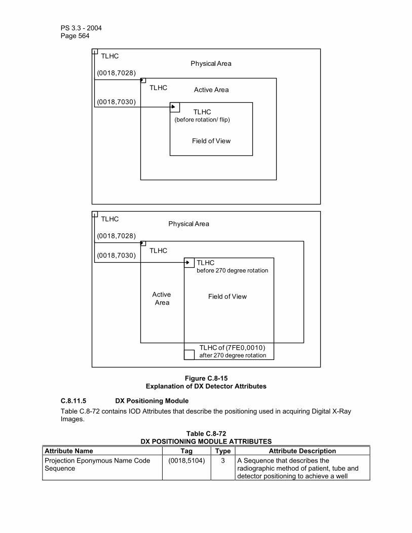
PS 3.3 - 2004 Page 564
TLHC
TLHC Active Area
Field of View
Physical Area(0018,7028)
(0018,7030)TLHC
(before rotation/ flip)
TLHC of (7FE0,0010)after 270 degree rotation
TLHC
TLHC
ActiveArea
Field of View
Physical Area
(0018,7028)
(0018,7030)TLHCbefore 270 degree rotation
Figure C.8-15 Explanation of DX Detector Attributes
C.8.11.5 DX Positioning Module Table C.8-72 contains IOD Attributes that describe the positioning used in acquiring Digital X-Ray Images.
Table C.8-72 DX POSITIONING MODULE ATTRIBUTES
Attribute Name Tag Type Attribute Description Projection Eponymous Name Code Sequence
(0018,5104) 3 A Sequence that describes the radiographic method of patient, tube and detector positioning to achieve a well

PS 3.3 - 2004 Page 565
described projection or view. Only a single Item shall be permitted in this Sequence. Shall be consistent with the other Attributes in this Module, if present, but may more specifically describe the image acquisition.
>Include ‘Code Sequence Macro’ Table 8.8-1. Baseline Context ID 4012 Patient Position (0018,5100) 3 Description of imaging subject’s position
relative to the equipment. See C.7.3.1.1.2 for Defined Terms and further explanation. If present, shall be consistent with Patient Gantry Relationship Code Sequence (0054,0414) and Patient Orientation Modifier Code Sequence (0054,0412).
View Position (0018,5101) 3 Radiographic view of the image relative to the imaging subject’s orientation. Shall be consistent with View Code Sequence (0054,0220). See C.8.11.5.1.1 for further explanation.
View Code Sequence (0054,0220) 3 Sequence that describes the projection of the anatomic region of interest on the image receptor.
Note: It is strongly recommended that this Attribute be present, in order to ensure that images may be positioned correctly relative to one another for display.
Shall be consistent with View Position (0018,5101). See C.8.11.5.1.1 for further explanation. Only a single Item shall be permitted in this Sequence.
>Include ‘Code Sequence Macro’ Table 8.8-1. Baseline Context ID 4010 >View Modifier Code Sequence (0054,0222) 3 View modifier.
Zero or more Items may be included in this Sequence.
>>Include ‘Code Sequence Macro’ Table 8.8-1. Baseline Context ID 4011 Patient Orientation Code Sequence (0054,0410) 3 Sequence that describes the orientation of
the patient with respect to gravity. See C.8.11.5.1.2 for further explanation. Only a single Item shall be permitted in this Sequence.
>Include ‘Code Sequence Macro’ Table 8.8-1. Baseline Context ID 19 > Patient Orientation Modifier Code (0054,0412) 3 Patient Orientation Modifier.

PS 3.3 - 2004 Page 566
Sequence Required if needed to fully specify the orientation of the patient with respect to gravity. Only a single Item shall be permitted in this Sequence.
>>Include ‘Code Sequence Macro’ Table 8.8-1. Baseline Context ID 20 Patient Gantry Relationship Code Sequence
(0054,0414) 3 Sequence which describes the orientation of the patient with respect to the gantry. Only a single Item shall be permitted in this Sequence.
>Include ‘Code Sequence Macro’ Table 8.8-1. Baseline Context ID 21 Distance Source to Patient (0018,1111) 3 Distance in mm from source to the table,
support or bucky side that is closest to the Imaging Subject, as measured along the central ray of the X-Ray beam.
Note: 1. This definition is less useful in terms of estimating geometric magnification than a measurement to a defined point within the Imaging Subject, but accounts for what is realistically measurable in an automated fashion in a clinical setting.
2. This measurement does not take into account any air gap between the Imaging Subject and the “front” of the table or bucky.
3. If the detector is not mounted in a table or bucky, then the actual position relative to the patient is implementation or operator defined.
4. This value is traditionally referred to as Source Object Distance (SOD).
See C.8.11.7 Mammography Image Module for explanation if Positioner Type (0018,1508) is MAMMOGRAPHIC.
Distance Source to Detector (0018,1110) 3 Distance in mm from source to detector center.
Note: This value is traditionally referred to as Source Image Receptor Distance (SID).
See C.8.11.7 Mammography Image Module for explanation if Positioner Type (0018,1508) is MAMMOGRAPHIC.
Estimated Radiographic Magnification Factor
(0018,1114) 3 Ratio of Source Image Receptor Distance (SID) over Source Object Distance (SOD).
Positioner Type (0018,1508) 2 Defined Terms: CARM COLUMN

PS 3.3 - 2004 Page 567
MAMMOGRAPHIC PANORAMIC CEPHALOSTAT RIGID NONE
Notes: 1. The term CARM can apply to any positioner with 2 degrees of freedom of rotation of the X-Ray beam about the Imaging Subject.
2. The term COLUMN can apply to any positioner with 1 degree of freedom of rotation of the X-Ray beam about the Imaging Subject.
Positioner Primary Angle (0018,1510) 3 Position of the X-Ray beam about the patient from the RAO to LAO direction where movement from RAO to vertical is positive, if Positioner Type (0018,1508) is CARM. See C.8.7.5 XA Positioner Module for further explanation if Positioner Type (0018,1508) is CARM. See C.8.11.7 Mammography Image Module for explanation if Positioner Type (0018,1508) is MAMMOGRAPHIC.
Positioner Secondary Angle (0018,1511) 3 Position of the X-Ray beam about the patient from the CAU to CRA direction where movement from CAU to vertical is positive, if Positioner Type (0018,1508) is CARM. See C.8.7.5 XA Positioner Module for further explanation if Positioner Type (0018,1508) is CARM. See C.8.11.7 Mammography Image Module for explanation if Positioner Type (0018,1508) is MAMMOGRAPHIC.
Detector Primary Angle (0018,1530) 3 Angle of the X-Ray beam in the row direction in degrees relative to the normal to the detector plane. Positive values indicate that the X-Ray beam is tilted toward higher numbered columns. Negative values indicate that the X-Ray beam is tilted toward lower numbered columns. See C.8.7.5 XA Positioner Module for further explanation. See C.8.11.7 Mammography Image Module for explanation if Positioner Type (0018,1508) is MAMMOGRAPHIC.
Detector Secondary Angle (0018,1531) 3 Angle of the X-Ray beam in the column direction in degrees relative to the normal to the detector plane. Positive values indicate that the X-Ray beam is tilted

PS 3.3 - 2004 Page 568
toward lower numbered rows. Negative values indicate that the X-Ray beam is tilted toward higher numbered rows. See C.8.7.5 XA Positioner Module for further explanation. See C.8.11.7 Mammography Image Module for explanation if Positioner Type (0018,1508) is MAMMOGRAPHIC.
Column Angulation (0018,1450) 3 Angle of the X-Ray beam in degree relative to an orthogonal axis to the detector plane. Positive values indicate that the tilt is toward the head of the table.
Note: The detector plane is assumed to be parallel to the table plane.
Only meaningful if Positioner Type (0018,1508) is COLUMN.
Table Type (0018,113A) 3 Defined Terms: FIXED TILTING NONE
Table Angle (0018,1138) 3 Angle of table plane in degrees relative to horizontal plane [Gravity plane]. Positive values indicate that the head of the table is upward. Only meaningful if Table Type (0018,113A) is TILTING.
Body Part Thickness (0018,11A0) 3 The average thickness in mm of the body part examined when compressed, if compression has been applied during exposure.
Compression Force (0018,11A2) 3 The compression force applied to the body part during exposure, measured in Newtons.
C.8.11.5.1 DX Positioning Attribute Descriptions C.8.11.5.1.1 View Code Sequence View Code Sequence (0054,0220) replaces the function of View Position (0018,5101), and describes the radiographic view of the image relative to the real-world patient orientation as described in Annex E.
C.8.11.5.1.2 Patient Orientation Code Sequence This Attribute is not related to Patient Orientation (0020,0020) and conveys a different concept entirely.
C.8.11.6 Mammography Series Module Table C.8-73 specifies the Attributes which identify and describe general information about a Digital Mammography Series.

PS 3.3 - 2004 Page 569
Table C.8-73 MAMMOGRAPHY SERIES MODULE ATTRIBUTES
Attribute Name Tag Type Attribute Description Modality (0008,0060) 1 Type of equipment that originally acquired
the data used to create the images in this Series. Enumerated Value: MG See section C.7.3.1.1.1 for further explanation.
C.8.11.7 Mammography Image Module Table C.8-74 contains IOD Attributes that describe a Digital Mammography X-Ray Image including its acquisition and positioning.
Table C.8-74 MAMMOGRAPHY IMAGE MODULE ATTRIBUTES
Attribute Name Tag Type Attribute Description Positioner Type (0018,1508) 1 Enumerated Values:
MAMMOGRAPHIC NONE
Distance Source to Detector (0018,1110) 3 Distance in mm from source to detector center on the chest wall line
Notes: 1. This value is traditionally referred to as Source Image Distance (SID).
2. See C.8.11.7.1.1.
Distance Source to Patient (0018,1111) 3 Distance in mm from source to the bucky side that is closest to the Imaging Subject, as measured along the X-Ray beam vector.
Notes: 1. This value is traditionally referred to as Source Object Distance (SOD).
2. See notes for this attribute in C.8.11.5 DX Positioning Module.
3. See C.8.11.7.1.1 for description of X-Ray beam vector.
Positioner Primary Angle (0018,1510) 3 Position in degrees of the X-Ray beam vector in the coronal anatomical plane as if the patient were standing where movement of the X-Ray source from right to vertical is positive, and vertical is zero.
Positioner Secondary Angle (0018,1511) 3 Position in degrees of the X-Ray beam vector in the sagittal anatomical plane as if the patient were standing where movement of the X-Ray source from anterior to posterior is positive, and vertical is zero.
Image Laterality (0020,0062) 1 Laterality of the region examined. Enumerated Values:

PS 3.3 - 2004 Page 570
R = right L = left B = both (e.g. cleavage)
Organ Exposed (0040,0318) 1 Organ to which Organ Dose (0040,0316) applies. Enumerated Value: BREAST
Note: In the Mammography IOD, Organ Dose (0040,0316) refers to the mean glandular dose.
Implant Present (0028,1300) 3 Whether or not an implant is present. Enumerated Values: YES NO
Partial View (0028,1350) 3 Indicates whether this image is a partial view, that is a subset of a single view of the breast. Enumerated Values: YES, NO If this Attribute is absent, then the image may or may not be a partial view.
Note: This may occur when a breast is larger than the active area of the detector.
Partial View Description (0028,1351) 3 Free text description of the portion of the breast captured in a partial view image.
Include 'General Anatomy Mandatory Macro' Table 10-5 Defined Context ID for the Anatomic Region Sequence is 4013.
View Code Sequence (0054,0220) 1 Sequence that describes the projection of the anatomic region of interest on the image receptor. Only a single Item shall be permitted in this Sequence.
>Include ‘Code Sequence Macro’ Table 8.8-1. Enumerated Value for Context ID is 4014. >View Modifier Code Sequence (0054,0222) 2 View modifier.
Zero or more Items may be included in this Sequence.
>>Include ‘Code Sequence Macro’ Table 8.8-1. Enumerated Value for Context ID is 4015.
C.8.11.7.1 Mammography Image Attribute Descriptions C.8.11.7.1.1 Mammography X-Ray Beam and X-ray Beam Vector Definition Figure C.8-8 shows the X-Ray beam for a digital mammography system. The X-Ray beam vector is defined from the Focal Spot to the center of the chest wall line of the Image Detection device.

PS 3.3 - 2004 Page 571
Z Z
XY
Positive rotation / Y
Image plane
O O
Positive rotation / X
X-Ray Beam
X-Ray Beam Vector
Figure C.8-8
C.8.11.7.1.2 Detector Primary and Secondary Angles Detector Angles are defined in a fashion similar to the positioner angles, except that the angle of the x-ray beam vector is relative to the detector plane rather than the patient plane. Zero degrees is referenced to the normal of the detector plane pointing toward the x-ray source. The valid range of the Detector Angles is -90 to + 90 degrees. The Primary Axis of rotation is defined along the line in the column direction of the detector plane which intersects the x-ray beam vector. The Detector Primary Angle is defined in the plane perpendicular to the Primary Axis of rotation at the point where the x-ray beam vector intersects the detector plane, with zero degrees in the direction normal to the detector plane and +90 in the direction of the higher numbered columns of the detector in that plane. The valid range of Detector Primary Angle is -90 to +90 degrees. The Secondary Axis is in the detector plane and is perpendicular to the Primary Axis at the intersection of the beam vector with the detector plane (i.e., it is along the row direction). The Detector Secondary Angle is defined in the plane perpendicular to the Secondary Axis at the point where the x-ray beam vector intersects the detector plane, with zero degrees in the direction normal to the detector plane. +90 degrees corresponds to the direction of the lower numbered rows of the detector in that plane. The Detector Secondary Angle range is -90 to + 90 degrees.
C.8.11.8 Intra-oral Series Module Table C.8-75 specifies the Attributes which identify and describe general information about a Digital Intra-oral X-Ray Series.
Table C.8-75 INTRA-ORAL SERIES MODULE ATTRIBUTES
Attribute Name Tag Type Attribute Description Modality (0008,0060) 1 Type of equipment that originally acquired
the data used to create the images in this Series.

PS 3.3 - 2004 Page 572
Enumerated Values: IO See section C.7.3.1.1.1 for further explanation.
C.8.11.9 Intra-oral Image Module Table C.8-76 contains IOD Attributes that describe a Digital Intra-oral X-Ray Image including its acquisition and positioning.
Table C.8-76 INTRA-ORAL IMAGE MODULE ATTRIBUTES
Attribute Name Tag Type Attribute Description Positioner Type (0018,1508) 1 Enumerated Values:
NONE CEPHALOSTAT RIGID
Image Laterality (0020,0062) 1 Laterality of the region examined. Enumerated Values: R = right L = left B = both (i.e. midline)
Anatomic Region Sequence (0008,2218) 1
Sequence that identifies the anatomic region of interest in this image. Only a single Item shall be permitted in this Sequence.
>Include ‘Code Sequence Macro’ Table 8.8-1. DefinedContext ID 4016. >Anatomic Region Modifier Sequence (0008,2220) 1C
Sequence that refines the anatomic region of interest in this image. Required if Primary Anatomic Structure Sequence (0008,2228) is not sent. Only a single Item shall be permitted in this Sequence.
>>Include ‘Code Sequence Macro’ Table 8.8-1. DefinedContext ID 4017. Primary Anatomic Structure Sequence (0008,2228) 1C Sequence that describes the primary
anatomic structures of interest in this image. See C.8.11.9.1.1 for further explanation. Required if Anatomic Region Modifier Sequence (0008,2220) is not sent. One or more Items may be included in this Sequence.
>Include ‘Code Sequence Macro’ Table 8.8-1. DefinedContext ID 4018 or 4019. See C.8.11.9.1.1 for further explanation.

PS 3.3 - 2004 Page 573
C.8.11.9.1 Intra-oral Image Attribute Descriptions C.8.11.9.1.1 Primary Anatomic Structure Sequence The Code Value (0008,0100) shall be drawn from the DICOM Content Mapping Resource, Context ID 4018, for permanent dentition, or Context ID 4019 for deciduous dentition.
These Context Groups correspond to ISO 3950-1984 that describes a designation of permanent and deciduous dentition using a two digit code, the first digit of which designates a quadrant, and the second digit a tooth.
The teeth imaged shall be listed as multiple Items in the Primary Anatomic Structure Sequence (0008,2228).

PS 3.3 - 2004 Page 574
C.8.12 VL Modules C.8.12.1 VL Image Module Table C.8-77 specifies the Attributes that describe a VL Image produced by Endoscopy (ES), General Microscopy (GM), Automated-Stage Microscopy (SM), External-camera Photography (XC), or other VL imaging Modalities.
Table C.8-77 VL IMAGE MODULE ATTRIBUTES
Attribute Name Tag Type Attribute Description Image Type (0008,0008) 1 Image identification characteristics.
See C.8.12.1.1.6 for specialization. Photometric Interpretation
(0028,0004) 1 Specifies the intended interpretation of the pixel data. See C.8.12.1.1.1 for specialization of this Attribute.
Bits Allocated (0028,0100) 1 Number of bits allocated for each pixel sample. Each sample shall have the same number of bits allocated. See C.8.12.1.1.2 for specialization of this Attribute. See PS 3.5 for further explanation.
Bits Stored (0028,0101) 1 Number of bits stored for each pixel sample. Each sample shall have the same number of bits stored. See C.8.12.1.1.2 for specialization of this Attribute. See PS 3.5 for further explanation.
High Bit (0028,0102) 1 Most significant bit for pixel sample data. Each sample shall have the same high bit. See C.8.12.1.1.2 for specialization of this Attribute. See PS 3.5 for further explanation.
Pixel Representation
(0028,0103) 1 Data representation of the pixel samples. Each sample shall have the same pixel representation. See Section C.8.12.1.1.3 for specialization of this Attribute.
Samples per Pixel (0028,0002) 1 Number of samples (planes) per image. See C.8.12.1.1.4 for specialization of this Attribute.
Planar Configuration
(0028,0006) 1C Indicates whether the pixel data are sent color-by-plane or color-by-pixel. Required if Samples per Pixel (0028,0002) has a value greater than 1. See C.8.12.1.1.5 for specialization of this Attribute.
Content Time (0008,0033) 1C The time the image pixel data creation started. Required if the Image is part of a series in which the images are temporally related.
Note: This Attribute was formerly known as Image Time.
Lossy Image Compression
(0028,2110) 2 Specifies whether an Image has undergone lossy compression. Enumerated Values:
00 = Image has NOT been subjected to lossy compression.
01 = Image has been subjected to lossy compression.
See C.7.6.1.1.5 Referenced Image (0008,1140) 1C A Sequence that references other images significantly

PS 3.3 - 2004 Page 575
Sequence related to this image. One or more items may be included in this sequence. Required if Image Type (0008,0008) Value 3 is present and has a value of "STEREO L" or "STEREO R". May also be present otherwise. See Section C.8.12.1.1.7.
> Referenced SOP Class UID
(0008,1150) 1 Uniquely identifies the referenced SOP Class.
> Referenced SOP Instance UID
(0008,1155) 1 Uniquely identifies the referenced SOP Instance.
>Referenced Frame Number
(0008,1160) 3 References one or more image frames of a Multi-frame Image SOP Instance, identifying which frames are significantly related to this image, if the reference is not to all frames.
Note: If this Attribute is not present, all frames of the SOP Instance are referenced.
>Purpose of Reference Code Sequence
(0040,A170) 2 Describes the purpose for which the reference is made. Onlya single Item shall be permitted in this Sequence.
>>Include Code Sequence Macro Table 8.8-1
Defined Context ID 7201
Window Center (0028,1050) 3 Window Center for display. See C.11.2.1.2 for further explanation. Meaningful only if Photometric Interpretation (0028,0004) is MONOCHROME2.
Window Width (0028,1051) 1C Window Width for display. See C.11.2.1.2 for further explanation. Required if Window Center (0028, 1050) is present.
Anatomic Region Sequence
(0008,2218) 1C
Sequence that identifies the anatomic region of interest in this image (i.e. external anatomy, surface anatomy, or general region of the body). Only a single Item shall be permitted in this sequence. Required if Number of Frames (0028,0008) is present and Specimen Accession Number (0040,050A) is absent. May be present otherwise.
>Include ‘Code Sequence Macro’ Table 8.8-1
DCID 4040 is defined for the Video Endoscopic IOD. For other IODs, no Context ID is defined.
>Anatomic Region Modifier Sequence
(0008,2220) 3 Sequence of Items that modifies the anatomic region of interest of this image One or more Items may be included in this Sequence.
>>Include ‘Code Sequence Macro’ Table 8.8-1
Baseline Context ID is 2 .
Include ‘Primary Anatomic Structure Macro’ Table 10.x-4
No Context ID is defined.

PS 3.3 - 2004 Page 576
C.8.12.1.1 VL Image Module Attribute Descriptions C.8.12.1.1.1 Photometric Interpretation The Enumerated Values of Photometric Interpretation (0028,0004) shall be:
MONOCHROME2 RGB YBR_FULL_422 YBR_FULL_420 YBR_RCT YBR_ICT
Note: There is no formal color space defined, hence “false” color applications that encode near-visible light images may be encoded, for example, as RGB.
C.8.12.1.1.2 Bits Allocated, Bits Stored, and High Bit The Enumerated Value of Bits Allocated (0028,0100) shall be 8; the Enumerated Value of Bits Stored (0028,0101) shall be 8; and the Enumerated Value of High Bit (0028,0102) shall be 7.
C.8.12.1.1.3 Pixel Representation The Enumerated Value of Pixel Representation (0028,0103) shall be 0.
C.8.12.1.1.4 Samples per Pixel The Enumerated Values of Samples per Pixel (0028,0002) shall be as follows: If the value of Photometric Interpretation (0028,0004) is MONOCHROME2, then the Enumerated Value of Samples per Pixel (0028,0002) shall be one (1). If the value of Photometric Interpretation (0028,0004) is RGB or YBR_FULL_422 or YBR_FULL_420 or YBR_RCT or YBR_ICT, then the Enumerated Value of Samples per Pixel (0028,0002) shall be three (3).
C.8.12.1.1.5 Planar Configuration If present, the Enumerated Value of Planar Configuration (0028,0006) shall be 0. This value shall be present if Samples per Pixel (0028,0002) has a value greater than 1.
C.8.12.1.1.6 Image Type The Image Type attribute identifies important image characteristics in a multiple valued data element. For Visible Light, Image Type is specialized as follows:
a. Value 1 shall identify the Pixel Data Characteristics in accordance with Section C.7.6.1.1.2; Enumerated Values are: ORIGINAL and DERIVED;
b. Value 2 shall identify the Patient Examination Characteristics in accordance with Section C.7.6.1.1.2; Enumerated Values are: PRIMARY and SECONDARY.
c. Value 3 may be absent, but if present shall identify the members of a stereo pair, in which case Referenced Image Sequence (0008,1140) is used to identify the other member of the pair. If present, the Enumerated Values are: STEREO L Image is the left image (relative to the observer's left) of a
stereo pair acquisition;
STEREO R Image is the right image (relative to the observer's right) of a stereo pair acquisition.

PS 3.3 - 2004 Page 577
d. Other Values are implementation specific (optional).
C.8.12.1.1.7 Referenced Image Sequence When Image Type (0008,0008) Value 3 is STEREO L or STEREO R, Referenced Image Sequence (0008,1140) shall be used to identify the corresponding SOP Instance of the Stereoscopic acquisition. In this case, either:
- only a single item shall be present, or - multiple items may be present, each with the Purpose of Reference Code Sequence
(0040,A170) present, and only the first item having the Purpose of Reference value (121315, DCM, “Other image of stereoscopic pair”).
C.8.12.2 Slide Coordinates Module The table in this Section contains Attributes that describe Slide Coordinates. Slide Coordinates provide a means to position a robotic Microscope Stage reproduceably with respect to the pixel plane of the digital Microscope.
Note: There is no a priori correspondence of pixels to Slide Coordinates. Therefore, the geometrical symmetry point through the pixel plane of the digital microscope may not correspond to the center of a pixel. The geometrical symmetry point could be between pixels.
Table C.8-78
Slide Coordinates Module Attributes Attribute Name Tag Type Attribute Description
Image Center Point Coordinates Sequence
(0040,071A) 2 The coordinates of the center point of the Image in the Slide Coordinate System Frame of Reference. This sequence shall contain exactly one item. See Section C.8.12.2.1.1 of this Part for further explanation.
>X Offset in Slide Coordinate System
(0040,072A) 1C The X offset in millimeters from the Origin of the Slide Coordinate System. See Figure C.8-16. Required if a sequence item is present.
>Y Offset in Slide Coordinate System
(0040,073A) 1C The Y offset in millimeters from the Origin of the Slide Coordinate System. See Figure C.8-16. Required if a sequence item is present.
>Z Offset in Slide Coordinate System
(0040,074A) 2C The Z offset in microns from the image substrate reference plane (i.e. utilized surface of a glass slide). Required if a sequence item is present.
Pixel Spacing Sequence (0040,08D8) 3 Physical distance in the Imaging Subject, i.e. Patient or Specimen, between the center of each pixel along specified axes. One or more items may be present.
>Coordinate System Axis Code Sequence
(0040,08DA) 1C Axis of a coordinate system. This sequence shall contain exactly one item.
>>Include ‘Code Sequence Macro’ Table 8.8-1 Baseline Context ID is 95. >Numeric Value (0040,A30A) 1C The distance between the center-points of adjacent
pixels along the axis specified by Coordinate System Axis Code Sequence (0040,08DA). Required if a sequence item is present.
>Measurement Units (0040,08EA) 1C Units of the measurement. This sequence shall

PS 3.3 - 2004 Page 578
Code Sequence contain exactly one item. Required if a sequence item is present.
>>Include ‘Code Sequence Macro’ Table 8.8-1 Baseline Context ID is 82.
C.8.12.2.1 Slide Coordinates Attribute Descriptions C.8.12.2.1.1 Image Center Point Coordinates Sequence This Section defines the Slide Coordinate System and specifies the Attributes that shall be used to describe the location of the center point of the Image pixel plane (as captured through a microscope) in the Slide Coordinate System Frame of Reference.
Note: In Slide Microscopy (SM), the Microscope is equipped with a moveable Stage and position sensors that enable storage of the location of the center point of the displayed image with respect to the examined Specimen.
The Stage is the part of the Microscope to which the Slide is attached for viewing. The Objective Lens is the lens that is closest to the Specimen. The Top Surface of the Slide is the surface of the Slide on which the Specimen in Mounted. The Bottom Surface of the Slide is the opposite surface. This Specification presumes that: 1) the Slide is rectangular; 2) the Top Surface of the Slide is oriented toward the Objective Lens of the Microscope; and 3) the Bottom Surface of the Slide is in perfect contact with the Microscope Stage when the Slide is attached to the Stage for viewing.
Notes: 1. The Label of the Slide is presumed to be mounted-on or written-on the Top Surface of the Slide.
2. Specification of the mechanical form, function, or tolerances of the Microscope are outside the scope of this Standard.
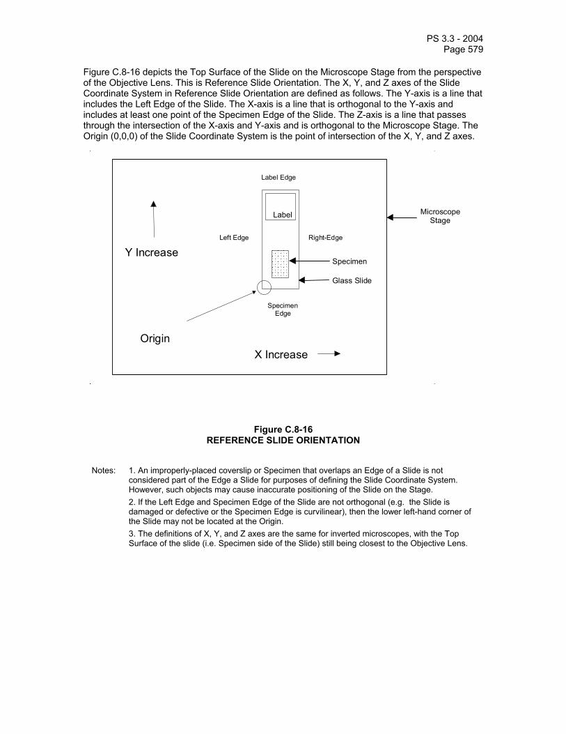
PS 3.3 - 2004 Page 579
Figure C.8-16 depicts the Top Surface of the Slide on the Microscope Stage from the perspective of the Objective Lens. This is Reference Slide Orientation. The X, Y, and Z axes of the Slide Coordinate System in Reference Slide Orientation are defined as follows. The Y-axis is a line that includes the Left Edge of the Slide. The X-axis is a line that is orthogonal to the Y-axis and includes at least one point of the Specimen Edge of the Slide. The Z-axis is a line that passes through the intersection of the X-axis and Y-axis and is orthogonal to the Microscope Stage. The Origin (0,0,0) of the Slide Coordinate System is the point of intersection of the X, Y, and Z axes.
Origin
Label
Y Increase
X Increase
SpecimenEdge
Label Edge
Right-EdgeLeft Edge
Specimen
Glass Slide
MicroscopeStage
Figure C.8-16 REFERENCE SLIDE ORIENTATION
Notes: 1. An improperly-placed coverslip or Specimen that overlaps an Edge of a Slide is not considered part of the Edge a Slide for purposes of defining the Slide Coordinate System. However, such objects may cause inaccurate positioning of the Slide on the Stage.
2. If the Left Edge and Specimen Edge of the Slide are not orthogonal (e.g. the Slide is damaged or defective or the Specimen Edge is curvilinear), then the lower left-hand corner of the Slide may not be located at the Origin.
3. The definitions of X, Y, and Z axes are the same for inverted microscopes, with the Top Surface of the slide (i.e. Specimen side of the Slide) still being closest to the Objective Lens.

PS 3.3 - 2004 Page 580
Figure C.8-17 depicts the Z-axis center point location. The X-axis value of Image Center Point Location (0040,073A) shall increase from the Origin toward the Right Edge in Reference Slide Orientation. The Y-axis value of Image Center Point Location (0040,073A) shall increase from the Origin toward the Label Edge in Reference Slide Orientation. The Z-axis value of Image Center Point Location (0040,073A) shall be referenced as zero at the image substrate reference plane (i.e. utilized surface of a glass slide) and shall increase in a positive fashion coincident with increased distance from the substrate surface.
Origin
Z Increase Glass Slide Substrate
Specimen
Cover Slip
MICROSCOPE
Y Increase
Figure C.8-17 Z-AXIS CENTER POINT LOCATION, VIEW FROM RIGHT EDGE OF SLIDE

PS 3.3 - 2004 Page 581
C.8.13 Enhanced MR Image This section describes the specific modules for the Enhanced MR Image IOD.
C.8.13.1 Enhanced MR Image Module This section describes the Enhanced MR Image Module.
Table C.8-79 specifies the attributes of the Enhanced MR Image module.
Table C.8.-79 ENHANCED MR IMAGE MODULE ATTRIBUTES
Attribute Name Tag Type Attribute Description Include ' MR Image and Spectroscopy Instance Macro' Table C.8.13-2
Image Type (0008,0008) 1 Image characteristics. See C.8.16.1 and C.8.13.3.1.1.
Include Common CT/MR Image Description Macro' Table C.8.16-5
Include 'MR Image Description Macro' Table C.8.13-4 Samples per Pixel (0028,0002) 1 Number of samples (planes) in this image.
This value shall be 1. Photometric Interpretation (0028,0004) 1 Specifies the intended interpretation of the
pixel data. Enumerated Value: MONOCHROME2. See C.7.6.3.1.2 for definition of this term.
Bits Allocated (0028,0100) 1 Number of bits allocated for each pixel sample. Each sample shall have the same number of bits allocated. Enumerated Values: 8 and 16.
Bits Stored (0028,0101) 1 Number of bits stored for each pixel sample. Each sample shall have the same number of bits stored. Enumerated Values: 8, 12 and 16. See C.8.13.1.1.1 for specialization.
High Bit (0028,0102) 1 Most significant bit for pixel sample data. Each sample shall have the same high bit. Shall be one less than the value in Bits Stored (0028,0101).
Spacing between Slices (0018,0088) 3 Value of the prescribed spacing to be applied between the slices in a volume that is to be acquired. The spacing in mm is defined as the center-to-center distance of adjacent slices.
Lossy Image Compression (0028,2110) 1 Specifies whether an Image has undergone lossy compression. Enumerated Values:
00 = Image has NOT been subjected to lossy compression.
01 = Image has been subjected to lossy compression.

PS 3.3 - 2004 Page 582
See C.7.6.1.1.5 for further explanation. Lossy Image Compression Ratio (0028,2112) 1C Describes the approximate lossy
compression ratio(s) that have been applied to this image. See C.7.6.1.1.5 for further explanation. May be multivalued if successive lossy compression steps have been applied.
Note: For example, a compression ratio of 30:1 would be described in this Attribute with a single value of 30.
Required if Lossy Images Compression (0028,2110) is “01”.
Icon Image Sequence (0088,0200) 3 This icon image is representative of the Image.
> Include ‘Image Pixel Macro’ Table C.7-11b See Section F.7.
C.8.13.1.1 Enhanced MR Image Module Attribute Description C.8.13.1.1.1 Bits Allocated and Bits Stored Table C.8-80 specifies the allowed combinations of Bits Allocated (0028,0100) and Bits Stored (0028,0101).
Table C.8-80 ALLOWED COMBINATIONS OF ATTRIBUTE VALUES
FOR BITS ALLOCATED AND BITS STORED Bits Allocated Bits Stored
8 8 16 12, 16
C.8.13.2 MR Image and Spectroscopy Instance Macro Table C.8-81 specifies the common attributes Enhanced MR Image Module and MR Spectroscopy Module.
Table C.8-81 MR IMAGE AND SPECTROSCOPY INSTANCE MACRO
Attribute Name Tag Type Attribute Description Acquisition Number (0020,0012) 3 A number identifying the single continuous
gathering of data over a period of time that resulted in this image.
Acquisition Datetime (0008,002A) 1C The date and time that the acquisition of data started.
Note: The synchronization of this time with an external clock is specified in the synchronization Module in Acquisition Time synchronized (0018,1800).
Required if Image Type (0008,0008) Value 1 is ORIGINAL or MIXED. May be

PS 3.3 - 2004 Page 583
present otherwise. Acquisition Duration (0018,9073) 1C The time in seconds needed to run the
prescribed pulse sequence. See C.7.6.16.2.2.1 for further explanation. Required if Image Type (0008,0008) Value 1 is ORIGINAL or MIXED. May be present otherwise.
Referenced Raw Data Sequence (0008,9121) 3 A sequence that identifies the set of Raw Data SOP Class/Instance pairs of the Raw data which were used to derive this Image. One or more Items may be included in this Sequence.
>Include 'SOP Instance Reference Macro' Table C.17-3 Referenced Waveform Sequence (0008,113A) 3 References to waveforms acquired in
conjunction with this image. These Waveforms may or may not be temporally synchronized with this image. One or more Items may be included in this Sequence.
>Include 'SOP Instance Reference Macro' Table C.17-3 Referenced Image Evidence Sequence
(0008,9092) 1C Full set of Composite SOP Instances referred to inside the Referenced Image Sequences of this Enhanced MR Image SOP Instance. See C.8.13.2.1.2 for further explanation. One or more Items may be included in this sequence. Required if the Referenced Image Sequence (0008,1140) is present.
>Include 'SOP Instance Reference Macro' Table C.17-3 Source Image Evidence Sequence (0008,9154) 1C Full set of Composite SOP Instances
referred to inside the Source Image Sequences of this Enhanced MR Image SOP Instance. See C.8.13.2.1.2 for further explanation. One or more Items may be included in this sequence. Required if the Source Image Sequence (0008,2112) is present.
>Include 'SOP Instance Reference Macro' Table C.17-3 Referenced Grayscale Presentation State Sequence
(0008,9237) 1C References to Grayscale Presentation State instances acquired in conjunction with this instance.
Note: May only be used to reference Presentation States belonging to the acquired data and not to reference Presentation States generated subsequently such as

PS 3.3 - 2004 Page 584
during interpretation.
One or more Items may be included in this sequence. Required if Presentation State is generated during acquisition, shall not be present otherwise.
>Include 'SOP Instance Reference Macro' Table C.17-3 Content Qualification (0018,9004) 1 Content Qualification Indicator
Enumerated Values: PRODUCT RESEARCH SERVICE See C.8.13.2.1.1 for further explanation.
Resonant Nucleus (0018,9100) 1C Nucleus that is resonant at the transmitter frequency. Defined Terms: 1H 3HE 7LI 13C 19F 23NA 31P 129XE Required if Image Type (0008,0008) Value 1 is ORIGINAL or MIXED. May be present otherwise.
k-space Filtering (0018,9064) 1C Describes k-space filtering applied. Shall be NONE if no k-space filter. Defined Terms: COSINE COSINE_SQUARED FERMI GAUSSIAN HAMMING HANNING LORENTZIAN LRNTZ_GSS_TRNSFM RIESZ TUKEY NONE Required if Image Type (0008,0008) Value 1 is ORIGINAL or MIXED. May be present otherwise.
Magnetic Field Strength (0018,0087) 1C Nominal field strength of the MR Magnet, in Tesla. Required if Image Type (0008,0008) Value 1 is ORIGINAL or MIXED. May be present otherwise.

PS 3.3 - 2004 Page 585
Applicable Safety Standard Agency (0018,9174) 1 Agency that established MR safety standard applicable to the acquisition of this Instance. Defined Terms:
IEC FDA MHW
Applicable Safety Standard Description
(0018,9175) 3 Name and Version of the applicable standard.
Image Comments (0020,4000) 3 User-defined comments about the image.
C.8.13.2.1 MR Image and Spectroscopy Instance Macro Attribute Description C.8.13.2.1.1 Content Qualification Content Qualification (0018,9004) shall have the value PRODUCT if the content (image or Spectroscopy data) was produced with approved hardware and software. It shall have the value RESEARCH or SERVICE if there is any doubt as to whether the content was produced with approved hardware and software.
If data with Content Qualification (0018,9004) of RESEARCH or SERVICE is used to derive other content then it is expected that this derived content will also have Content Qualification (0018,9004) set to RESEARCH or SERVICE.
The intent of this element is to allow annotation of an advisory message that indicates that this content may not be suitable for clinical interpretation.
C.8.13.2.1.2 Evidence Sequence Attributes The intent of the Referenced Image Evidence Sequence (0008,9092) and Source Image Evidence Sequence (0008,9154) is to provide a list of all unique SOP Instances listed in the Referenced Image Sequence (0008,1140) and Source Image Sequence (0008,2112) attributes respectively.
C.8.13.3 MR Image Description Macro This section describes the MR Image Description Macro.
Table C.8-82 specifies the attributes of the MR Image Description Macro.
Table C.8-82 MR IMAGE DESCRIPTION MACRO ATTRIBUTES
Attribute Name Tag Type Attribute Description Complex Image Component (0008,9208) 1 Representation of complex data of frames
in the SOP Instance. See C.8.13.3.1.5 for a description and Defined Terms.
Acquisition Contrast (0008,9209) 1 Indication of acquisition contrast used with frames in the SOP Instance. See C.8.13.3.1.6 for a description and Defined Terms.

PS 3.3 - 2004 Page 586
C.8.13.3.1 MR Image Description Attribute Description C.8.13.3.1.1 Image Type and Frame Type The Image Type (0008,0008) and Frame Type (0008,9007) are not included in this Macro but one or the other is always included in the Module or Macro that invokes this Macro, and they are therefore described here.
In addition to the requirements specified in C.8.16.1 Image Type and Frame Type, the following additional requirements and Defined Terms are specified.
C.8.13.3.1.1.1 Pixel Data Characteristics Value 1 of Image Type (0008,0008) and Frame Type (0008,9007) is discussed in C.8.16.1.1. No additional requirements or Defined Terms.
C.8.13.3.1.1.2 Patient Examination Characteristics Value 2 of Image Type (0008,0008) and Frame Type (0008,9007) is discussed in C.8.16.1.2. No additional requirements or Defined Terms.
C.8.13.3.1.1.3 Image Flavor Table C.8-83 specifies the Defined Terms for MR additional to those defined in C.8.16.1.3 for Value 3 for Image Type (0008,0008) and Frame Type (0008,9007).

PS 3.3 - 2004 Page 587
Table C.8-83 MR-SPECIFIC IMAGE TYPE AND FRAME TYPE VALUE 3
Defined Term Name Defined Term Description ANGIO_TIME Angio time acquisition (peripheral
vascular/carotid) METABOLITE_MAP Metabolite Maps from spectroscopy data CINE Cardiac CINE DIFFUSION Collected to show diffusion effects. FLOW_ENCODED Flow Encoded FLUID_ATTENUATED Fluid Attenuated T2 weighted FMRI Collected for functional imaging calculations. MAX_IP Maximum Intensity Projection MIN_IP Minimum Intensity Projection M_MODE Image line over time METABOLITE_MAP Metabolite Maps from spectroscopy data MULTIECHO Multiple echoes with different contrast
weighting (e.g. proton density and T2 weighted) PROTON_DENSITY Proton density weighted REALTIME Real-time collection of single slices STIR Short Tau Inversion Recovery STRESS Cardiac stress image set TAGGING Images with superposition of thin saturation
bands TEMPERATURE Images record temperature T1 T1 weighted T2 T2 weighted T2_STAR T2* weighted TOF Time Of Flight weighted VELOCITY Velocity encoded
C.8.13.3.1.1.4 Derived Pixel Contrast Table C.8-84 specifies the Defined Terms for MR additional to those defined in C.8.16.1.4 for Value 4 for Image Type (0008,0008) and Frame Type (0008,9007).

PS 3.3 - 2004 Page 588
Table C.8-84 MR-SPECIFIC IMAGE TYPE AND FRAME TYPE VALUE 4
Defined Term Name Defined Term Description ADC Apparent Diffusion Coefficient DIFFUSION Diffusion weighted DIFFUSION_ANISO Diffusion Anisotropy DIFFUSION_ATTNTD Diffusion Attenuated. Derived by removing the T2
contributions from a Diffusion Weighted image. METABOLITE_MAP Metabolite Maps from spectroscopy data NEI Created through Negative Enhancement Integral operation R_COEFFICIENT R-Coefficient Map (fMRI) RHO Proton Density map SCM Signal Change Map SNR_MAP Signal to Noise Map T1_MAP T1 Map T2_STAR_MAP T2* Map T2_MAP T2 Map TCS Time Course of Signal TEMPERATURE Temperature encoded VELOCITY Velocity encoded
C.8.13.3.1.2 Pixel Presentation See C.8.16.2.1.1. No additional requirements or Defined Terms.
C.8.13.3.1.2.1 Supplemental Palette Color LUTs See C.8.16.2.1.1.1.
C.8.13.3.1.3 Volumetric Properties See C.8.16.2.1.2. No additional requirements or Defined Terms.
C.8.13.3.1.4 Volume Based Calculation Technique Attribute See C.8.16.2.1.3. No additional requirements or Defined Terms.
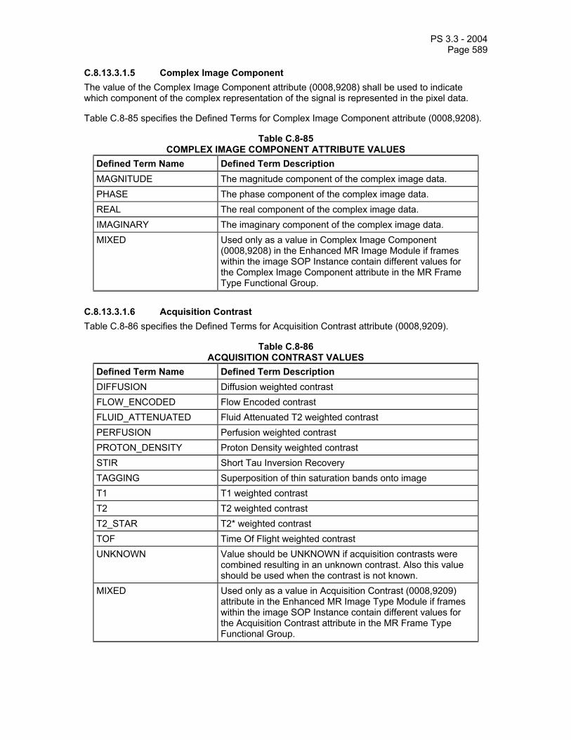
PS 3.3 - 2004 Page 589
C.8.13.3.1.5 Complex Image Component The value of the Complex Image Component attribute (0008,9208) shall be used to indicate which component of the complex representation of the signal is represented in the pixel data.
Table C.8-85 specifies the Defined Terms for Complex Image Component attribute (0008,9208).
Table C.8-85 COMPLEX IMAGE COMPONENT ATTRIBUTE VALUES
Defined Term Name Defined Term Description MAGNITUDE The magnitude component of the complex image data. PHASE The phase component of the complex image data. REAL The real component of the complex image data. IMAGINARY The imaginary component of the complex image data. MIXED Used only as a value in Complex Image Component
(0008,9208) in the Enhanced MR Image Module if frames within the image SOP Instance contain different values for the Complex Image Component attribute in the MR Frame Type Functional Group.
C.8.13.3.1.6 Acquisition Contrast Table C.8-86 specifies the Defined Terms for Acquisition Contrast attribute (0008,9209).
Table C.8-86 ACQUISITION CONTRAST VALUES
Defined Term Name Defined Term Description DIFFUSION Diffusion weighted contrast FLOW_ENCODED Flow Encoded contrast FLUID_ATTENUATED Fluid Attenuated T2 weighted contrast PERFUSION Perfusion weighted contrast PROTON_DENSITY Proton Density weighted contrast STIR Short Tau Inversion Recovery TAGGING Superposition of thin saturation bands onto image T1 T1 weighted contrast T2 T2 weighted contrast T2_STAR T2* weighted contrast TOF Time Of Flight weighted contrast UNKNOWN Value should be UNKNOWN if acquisition contrasts were
combined resulting in an unknown contrast. Also this value should be used when the contrast is not known.
MIXED Used only as a value in Acquisition Contrast (0008,9209) attribute in the Enhanced MR Image Type Module if frames within the image SOP Instance contain different values for the Acquisition Contrast attribute in the MR Frame Type Functional Group.

PS 3.3 - 2004 Page 590
C.8.13.4 MR Pulse Sequence Module The primary purpose of this module is to identify the pulse sequence and variations on that, which was used in creation of the image. Terminology is intended to be neutral, and allow equivalent sequences provided by different vendors to be classified the same.
Table C.8-87 specifies the attributes of the MR Pulse Sequence Module.
Table C.8-87 MR PULSE SEQUENCE MODULE ATTRIBUTES
Attribute Name Tag Type Attribute Description Pulse Sequence Name (0018,9005) 1C Name of the pulse sequence for
annotation purposes. Potentially vendor-specific name. Required if Image Type (0008,0008) Value 1 is ORIGINAL or MIXED. May be present otherwise.
MR Acquisition Type (0018,0023) 1C Identification of spatial data encoding scheme. Defined Terms: 1D 2D 3D Required if Image Type (0008,0008) Value 1 is ORIGINAL or MIXED. May be present otherwise.
Echo Pulse Sequence (0018,9008) 1C Echo category of pulse sequences. Enumerated Values: SPIN GRADIENT BOTH Required if Image Type (0008,0008) Value 1 is ORIGINAL or MIXED. May be present otherwise.
Multiple Spin Echo (0018,9011) 1C Multiple Spin Echo category of pulse sequence used to collect different lines in k-space for a single frame. Enumerated Values: YES NO Required if Image Type (0008,0008) Value 1 is ORIGINAL or MIXED and Echo Pulse sequence (0018,9008) equals SPIN or BOTH. Otherwise may be present if Image Type (0008,0008) Value 1 is DERIVED and Echo Pulse sequence (0018,9008) equals SPIN or BOTH.
Multi-planar Excitation (0018,9012) 1C Technique that simultaneously excites several volumes. Enumerated Values: YES
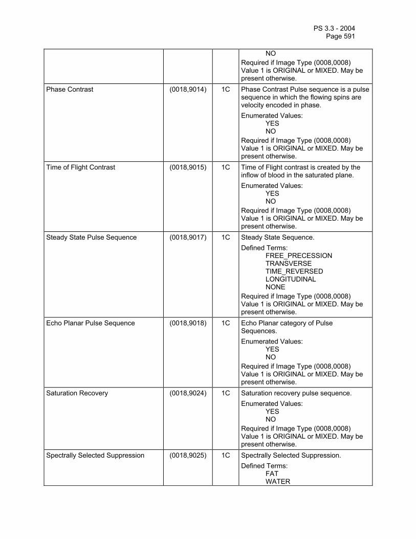
PS 3.3 - 2004 Page 591
NO Required if Image Type (0008,0008) Value 1 is ORIGINAL or MIXED. May be present otherwise.
Phase Contrast (0018,9014) 1C Phase Contrast Pulse sequence is a pulse sequence in which the flowing spins are velocity encoded in phase. Enumerated Values: YES NO Required if Image Type (0008,0008) Value 1 is ORIGINAL or MIXED. May be present otherwise.
Time of Flight Contrast (0018,9015) 1C Time of Flight contrast is created by the inflow of blood in the saturated plane. Enumerated Values: YES NO Required if Image Type (0008,0008) Value 1 is ORIGINAL or MIXED. May be present otherwise.
Steady State Pulse Sequence (0018,9017) 1C Steady State Sequence. Defined Terms: FREE_PRECESSION TRANSVERSE TIME_REVERSED LONGITUDINAL NONE Required if Image Type (0008,0008) Value 1 is ORIGINAL or MIXED. May be present otherwise.
Echo Planar Pulse Sequence (0018,9018) 1C Echo Planar category of Pulse Sequences. Enumerated Values: YES NO Required if Image Type (0008,0008) Value 1 is ORIGINAL or MIXED. May be present otherwise.
Saturation Recovery (0018,9024) 1C Saturation recovery pulse sequence. Enumerated Values: YES NO Required if Image Type (0008,0008) Value 1 is ORIGINAL or MIXED. May be present otherwise.
Spectrally Selected Suppression (0018,9025) 1C Spectrally Selected Suppression. Defined Terms: FAT WATER
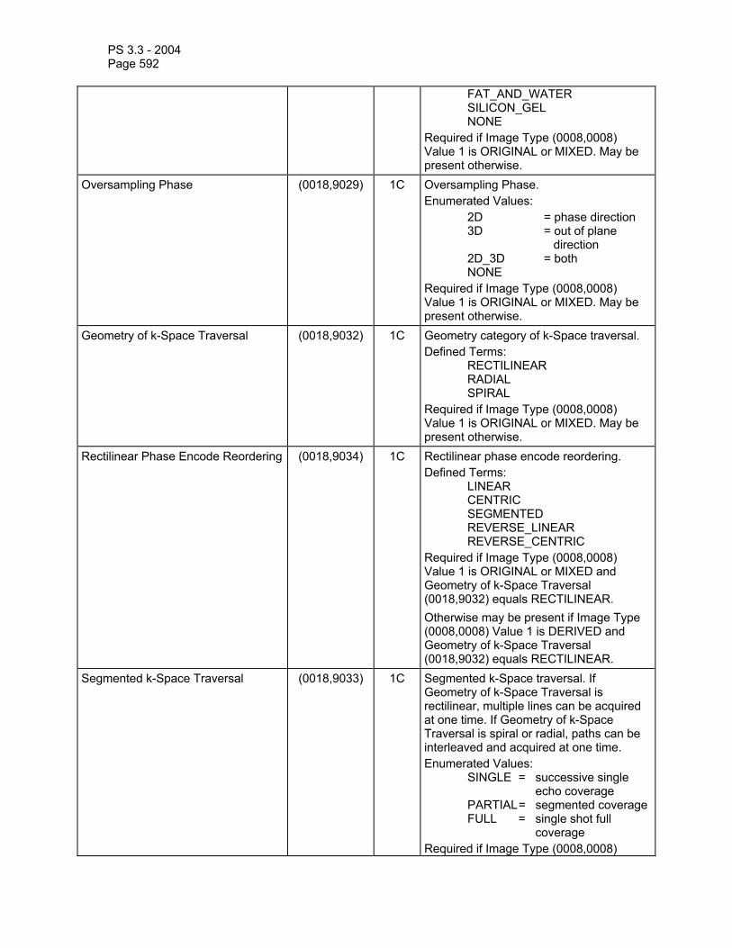
PS 3.3 - 2004 Page 592
FAT_AND_WATER SILICON_GEL NONE Required if Image Type (0008,0008) Value 1 is ORIGINAL or MIXED. May be present otherwise.
Oversampling Phase (0018,9029) 1C Oversampling Phase. Enumerated Values: 2D = phase direction
3D = out of plane direction
2D_3D = both NONE Required if Image Type (0008,0008) Value 1 is ORIGINAL or MIXED. May be present otherwise.
Geometry of k-Space Traversal (0018,9032) 1C Geometry category of k-Space traversal. Defined Terms: RECTILINEAR RADIAL SPIRAL Required if Image Type (0008,0008) Value 1 is ORIGINAL or MIXED. May be present otherwise.
Rectilinear Phase Encode Reordering (0018,9034) 1C Rectilinear phase encode reordering. Defined Terms: LINEAR CENTRIC SEGMENTED REVERSE_LINEAR REVERSE_CENTRIC Required if Image Type (0008,0008) Value 1 is ORIGINAL or MIXED and Geometry of k-Space Traversal (0018,9032) equals RECTILINEAR. Otherwise may be present if Image Type (0008,0008) Value 1 is DERIVED and Geometry of k-Space Traversal (0018,9032) equals RECTILINEAR.
Segmented k-Space Traversal (0018,9033) 1C Segmented k-Space traversal. If Geometry of k-Space Traversal is rectilinear, multiple lines can be acquired at one time. If Geometry of k-Space Traversal is spiral or radial, paths can be interleaved and acquired at one time. Enumerated Values: SINGLE = successive single
echo coverage PARTIAL = segmented coverage FULL = single shot full
coverage Required if Image Type (0008,0008)

PS 3.3 - 2004 Page 593
Value 1 is ORIGINAL or MIXED. May be present otherwise.
Coverage of k-Space (0018,9094) 1C Coverage of k-Space in the ky-kz plane. Defined Terms: FULL ELLIPTICAL WEIGHTED Required if Image Type (0008,0008) Value 1 is ORIGINAL or MIXED and MR Acquisition Type (0018,0023) equals 3D. Otherwise may be present if Image Type (0008,0008) Value 1 is DERIVED and MR Acquisition Type (0018,0023) equals 3D.
Number of k-Space Trajectories (0018,9093) 1C Number of interleaves or shots. Required if Image Type (0008,0008) Value 1 is ORIGINAL or MIXED. May be present otherwise.
C.8.13.5 Enhanced MR Image Functional Group Macros The following sections contain Functional Group macros specific to the Enhanced MR Image IOD.
Note: The attribute descriptions in the Functional Group Macros are written as if they were applicable to a single frame (i.e., the macro is part of the Per-frame Functional Groups Sequence). If an attribute is applicable to all frames (i.e. the macro is part of the Shared Functional Groups Sequence) the phrase "this frame" in the attribute description shall be interpreted to mean " for all frames".".
C.8.13.5.1 MR Image Frame Type Macro Table C.8-88 specifies the attributes of the MR Image Frame Type Functional Group macro.
Table C.8-88 MR IMAGE FRAME TYPE MACRO ATTRIBUTES
Attribute Name Tag Type Attribute Description MR Image Frame Type Sequence (0018,9226) 1 Identifies the characteristics of this frame.
Only a single Item shall be permitted in this sequence.
>Frame Type (0008,9007) 1 Type of Frame. A multi-valued attribute analogous to the Image Type (0008,0008). Enumerated Values and Defined Terms are the same as those for the four values of the Image Type (0008,0008) attribute, except that the value MIXED is not allowed. See C.8.16.1 and C.8.13.3.1.1.
>Include Common CT/MR Image Description Macro' Table C.8.16-5
>Include 'MR Image Description Macro' Table C.8.13-4

PS 3.3 - 2004 Page 594
C.8.13.5.2 MR Timing and Related Parameters Macro Table C.8-89 specifies the attributes of the MR Timing and Related Parameters Functional Group macro.
Table C.8-89 MR TIMING AND RELATED PARAMETERS MACRO ATTRIBUTES
Attribute Name Tag Type Attribute Description MR Timing and Related Parameters Sequence
(0018,9112) 1 Identifies the timing and safety information of this frame. Only a single Item shall be permitted in this sequence.
>Repetition Time (0018,0080) 1C The time in ms between two successive excitations of the same volume. Shall be 0 (zero) if there is a single excitation per volume. Required if Frame Type (0008,9007) Value 1 of this frame is ORIGINAL. May be present otherwise.
>Flip Angle (0018,1314) 1C Steady state angle in degrees to which the magnetic vector is flipped from the magnetic vector of the primary field. Required if Frame Type (0008,9007) Value 1 of this frame is ORIGINAL. May be present otherwise.
>Echo Train Length (0018,0091) 1C Number of lines in k-space acquired per excitation of the same volume regardless of the type of echo or the number of frames derived from them. See section C.8.12.5.2.1. Required if Frame Type (0008,9007) Value 1 of this frame is ORIGINAL. May be present otherwise.
>RF Echo Train Length (0018,9240) 1C Number of RF echoes collected per RF shot (or excitation) per frame. A value of zero shall correspond to a pure gradient echo frame. Note that this value corresponds to the current frame. Several frames may be derived from the same shot. See section C.8.13.5.2.1. Required if Frame Type (0008,9007) Value 1 of this frame is ORIGINAL. May be present otherwise.
>Gradient Echo Train Length (0018,9241) 1C Number of gradient echoes collected per RF echo per shot (or excitation) per frame. A value of zero shall correspond to a pure RF echo frame. If RF Echo Train Length (0018,9240) is non zero and Gradient Echo Train Length is as well then only the central echo will be an RF Spin Echo, all others will be gradient echoes. See section C.8.13.5.2.1. Required if Frame Type (0008,9007)

PS 3.3 - 2004 Page 595
Value 1 of this frame is ORIGINAL. May be present otherwise.

PS 3.3 - 2004 Page 596
>Specific Absorption Rate Sequence (0018,9239) 1C Sequence containing the methods of SAR calculation and the corresponding values. One or more items may be present. Required if the system is capable of calculating Specific Absorption Rate (0018,9181).
>>Specific Absorption Rate Definition
(0018,9179) 1 Specification of the method of SAR calculation as defined in Applicable Safety Standard Description (0018,9174). Defined Terms:
IEC_WHOLE_BODY IEC_PARTIAL_BODY IEC_HEAD IEC_LOCAL
>>Specific Absorption Rate Value (0018,9181) 1 Specific Absorption Rate in W/kg. >Gradient Output Type (0018,9180) 1C Definition of gradient output unit, for
which the value is stored in Gradient Output (0018,9182). Defined Terms:
DB_DT = in T/s ELECTRIC_FIELD = in V/m PER_NERVE_STIM = percentage
of peripheral nerve stimulation
Required if the system is capable of calculating Gradient Output (0018,9182).
>Gradient Output (0018,9182) 1C Unit is defined by Gradient Output Type (0018,9180). Required if the system is capable of calculating Gradient Output (0018,9182).
>Operating Mode Sequence (0018,9176) 1C Sequence of operating mode information relating to the frame/SOP instance as required to adhere to the Applicable Safety Standard Agency (0018,9174) regulations. One or more Items may be included in this sequence. Required if required by law or regulations. May be present otherwise.
>>Operating Mode Type (0018,9177) 1 Defined Terms: STATIC FIELD RF GRADIENT
>>Operating Mode (0018,9178) 1 Operating mode applicable for the defined by the applicable standard. Defined Terms:
IEC_NORMAL IEC_FIRST_LEVEL IEC_SECOND_LEVEL

PS 3.3 - 2004 Page 597
C.8.13.5.2.1 RF Echo Train Length and Gradient Echo Train Length Attributes Usage The three Echo Train Length attributes all specify information related to the pulse sequence, one or more frames, and the echo type. The following examples illustrate their usage.
For a sequence with each excitation/shot producing 2 spin echoes that produce a line of k-Space for 2 different frames, the following values would be used for each frame:
Echo Train Length 2 Gradient Echo Train Length 0 RF Echo Train Length 1
For a sequence with each excitation/shot producing 2 gradient echoes that produce a line of k-Space for 2 different frames, the following values would be used:
Echo Train Length 2 Gradient Echo Train Length 1 RF Echo Train Length 0
For a sequence with each excitation/shot producing 8 spin echoes that produce 8 lines of k-Space for 1 frame, the following values would be used:
Echo Train Length 8 Gradient Echo Train Length 0 RF Echo Train Length 8
C.8.13.5.3 MR FOV/Geometry Macro Table C.8-90 specifies the attributes of the MR FOV/Geometry Functional Group macro.
Table C.8-90 MR FOV/GEOMETRY MACRO ATTRIBUTES
Attribute Name Tag Type Attribute Description MR FOV/Geometry Sequence (0018,9125) 1 Identifies the geometry parameters of this
frame. Only a single Item shall be permitted in this sequence.
>In-plane Phase Encoding Direction (0018,1312) 1C The axes of the in-plane phase encoding with respect to the frame. Enumerated Values: COLUMN ROW OTHER Required if Frame Type (0008,9007) Value 1 of this frame is ORIGINAL. May be present otherwise.
>MR Acquisition Frequency Encoding Steps
(0018,9058) 1C Number of Frequency Encoding steps (kx) acquired

PS 3.3 - 2004 Page 598
Required if Frame Type (0008,9007) Value 1 is ORIGINAL. May be present otherwise.
>MR Acquisition Phase Encoding Steps in-plane
(0018,9231) 1C Number of In-Plane Phase Encoding steps (ky) acquired Required if Frame Type (0008,9007) Value 1 is ORIGINAL. May be present otherwise.
>MR Acquisition Phase Encoding Steps out-of-plane
(0018,9232) 1C Number of Out-of-Plane Phase Encoding steps (kz) acquired Required if MR Acquisition Type (0018,0023) equals 3D and Frame Type (0008,9007) Value 1 is ORIGINAL. May be present otherwise.
>Percent Sampling (0018,0093) 1C Fraction of acquisition matrix lines acquired, expressed as a percent. Required if Frame Type (0008,9007) Value 1 of this frame is ORIGINAL. May be present otherwise.
>Percent Phase Field of View (0018,0094) 1C Ratio of field of view dimension in phase direction to field of view dimension in frequency direction, expressed as a percent. Required if Frame Type (0008,9007) Value 1 of this frame is ORIGINAL. May be present otherwise.
C.8.13.5.4 MR Echo Macro Table C.8-91 specifies the attributes of the MR Echo Functional Group macro.
Table C.8-91 MR ECHO MACRO ATTRIBUTES
Attribute Name Tag Type Attribute Description MR Echo Sequence (0018,9114) 1 Identifies echo timing of this frame. Only
a single Item shall be permitted in this sequence.
>Effective Echo Time (0018,9082) 1C The time in ms between the middle of the excitation pulse and the peak of the echo produced for kx=0. Required if Frame Type (0008,9007) Value 1 of this frame is ORIGINAL. May be present otherwise.
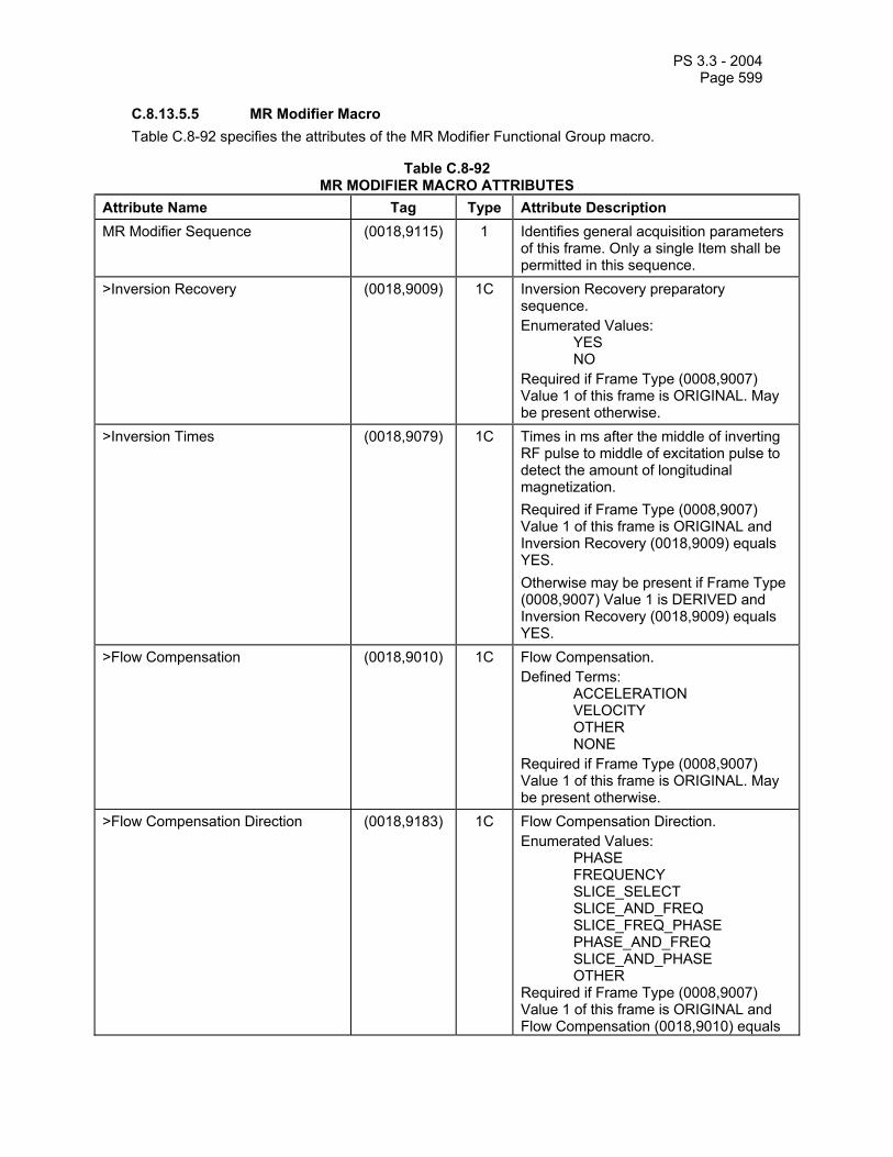
PS 3.3 - 2004 Page 599
C.8.13.5.5 MR Modifier Macro Table C.8-92 specifies the attributes of the MR Modifier Functional Group macro.
Table C.8-92 MR MODIFIER MACRO ATTRIBUTES
Attribute Name Tag Type Attribute Description MR Modifier Sequence (0018,9115) 1 Identifies general acquisition parameters
of this frame. Only a single Item shall be permitted in this sequence.
>Inversion Recovery (0018,9009) 1C Inversion Recovery preparatory sequence. Enumerated Values: YES NO Required if Frame Type (0008,9007) Value 1 of this frame is ORIGINAL. May be present otherwise.
>Inversion Times (0018,9079) 1C Times in ms after the middle of inverting RF pulse to middle of excitation pulse to detect the amount of longitudinal magnetization. Required if Frame Type (0008,9007) Value 1 of this frame is ORIGINAL and Inversion Recovery (0018,9009) equals YES. Otherwise may be present if Frame Type (0008,9007) Value 1 is DERIVED and Inversion Recovery (0018,9009) equals YES.
>Flow Compensation (0018,9010) 1C Flow Compensation. Defined Terms: ACCELERATION VELOCITY OTHER NONE Required if Frame Type (0008,9007) Value 1 of this frame is ORIGINAL. May be present otherwise.
>Flow Compensation Direction (0018,9183) 1C Flow Compensation Direction. Enumerated Values: PHASE FREQUENCY SLICE_SELECT SLICE_AND_FREQ SLICE_FREQ_PHASE PHASE_AND_FREQ SLICE_AND_PHASE OTHER Required if Frame Type (0008,9007) Value 1 of this frame is ORIGINAL and Flow Compensation (0018,9010) equals

PS 3.3 - 2004 Page 600
other than NONE. Otherwise may be present if Frame Type (0008,9007) Value 1 is DERIVED and Flow Compensation (0018,9010) equals other than NONE.
>Spoiling (0018,9016) 1C Spoiling. Enumerated Values:
RF = RF spoiled GRADIENT = gradient spoiled RF_AND_GRADIENT NONE
Required if Frame Type (0008,9007) Value 1 of this frame is ORIGINAL and Echo Pulse Sequence (0018,9008) equals GRADIENT or BOTH. Otherwise may be present if Frame Type (0008,9007) Value 1 is DERIVED and Echo Pulse Sequence (0018,9008) equals GRADIENT or BOTH.
>T2 Preparation (0018,9021) 1C T2 prepared Pulse Sequence. Enumerated Values: YES NO Required if Frame Type (0008,9007) Value 1 of this frame is ORIGINAL. May be present otherwise.
>Spectrally Selected Excitation (0018,9026) 1C Spectrally Selected Excitation. Enumerated Values:
WATER = water excitation FAT = fat excitation NONE
Required if Frame Type (0008,9007) Value 1 of this frame is ORIGINAL. May be present otherwise.
>Spatial Pre-saturation (0018,9027) 1C Spatial Pre-saturation. Defined Terms: SLAB NONE Required if Frame Type (0008,9007) Value 1 of this frame is ORIGINAL. May be present otherwise.
>Partial Fourier (0018,9081) 1C Partial Fourier. Enumerated Values: YES NO Required if Frame Type (0008,9007) Value 1 of this frame is ORIGINAL. May be present otherwise.
>Partial Fourier Direction (0018,9036) 1C Direction of Partial Fourier. Enumerated Values: PHASE

PS 3.3 - 2004 Page 601
FREQUENCY SLICE_SELECT COMBINATION Required if Frame Type (0008,9007) Value 1 of this frame is ORIGINAL and Partial Fourier (0018,9081) equals YES. Otherwise may be present if Frame Type (0008,9007) Value 1 is DERIVED and Partial Fourier (0018,9081) equals YES.
>Parallel Acquisition (0018,9077) 1C Parallel acquisition has been used to reduce measurement time. Enumerated Values: YES NO Required if Frame Type (0008,9007) Value 1 of this frame is ORIGINAL. May be present otherwise.
>Parallel Acquisition Technique (0018,9078) 1C Parallel acquisition characteristics. Defined Terms: PILS SENSE SMASH OTHER Required if Frame Type (0008,9007) Value 1 of this frame is ORIGINAL and Parallel Acquisition (0018,9077) equals YES. Otherwise may be present if Frame Type (0008,9007) Value 1 is DERIVED and Parallel Acquisition (0018,9077) equals YES.
>Parallel Reduction Factor In-plane (0018,9069) 1C Measurement time reduction factor expressed as ratio of original and reduced measurement time for the in-plane direction. Required if Frame Type (0008,9007) Value 1 of this frame is ORIGINAL and Parallel Acquisition (0018,9077) equals YES. Otherwise may be present if Frame Type (0008,9007) Value 1 is DERIVED and Parallel Acquisition (0018,9077) equals YES.
>Parallel Reduction Factor out-of-plane
(0018,9155) 1C Measurement time reduction factor expressed as ratio of original and reduced measurement time for the out-of-plane direction Required if Frame Type (0008,9007) Value 1 of this frame is ORIGINAL and Parallel Acquisition (0018,9077) equals YES.

PS 3.3 - 2004 Page 602
Otherwise may be present if Frame Type (0008,9007) Value 1 is DERIVED and Parallel Acquisition (0018,9077) equals YES.
>Parallel Reduction Factor Second In-plane
(0018,9168) 1C Measurement time reduction factor expressed as ratio of original and reduced measurement time for the second in-plane direction. Only required for MR Spectroscopy SOP Instances. Required if Frame Type (0008,9007) Value 1 of this frame is ORIGINAL and Parallel Acquisition (0018,9077) equals YES. Otherwise may be present if Frame Type (0008,9007) Value 1 is DERIVED and Parallel Acquisition (0018,9077) equals YES.

PS 3.3 - 2004 Page 603
C.8.13.5.6 MR Imaging Modifier Macro Table C.8-93 specifies the attributes of the MR Imaging Modifier Functional Group macro.
Table C.8-93 MR IMAGING MODIFIER MACRO ATTRIBUTES
Attribute Name Tag Type Attribute Description MR Imaging Modifier Sequence (0018,9006) 1 Identifies sequence containing MR
modifier Sequence Attributes. Only one item may be included in this sequence.
>Magnetization Transfer (0018,9020) 1C Magnetization Transfer pulse sequence. Enumerated Values: ON_RESONANCE OFF_RESONANCE NONE Required if Frame Type (0008,9007) Value 1 is ORIGINAL. May be present otherwise.
>Blood Signal Nulling (0018,9022) 1C Blood Signal Nulling (“Black Blood”) preparatory pulse sequence. Enumerated Values: YES NO Required if Frame Type (0008,9007) Value 1 is ORIGINAL. May be present otherwise.
>Tagging (0018,9028) 1C Tagging. Defined Terms: GRID LINE NONE Required if Frame Type (0008,9007) Value 1 is ORIGINAL. May be present otherwise.
>Tag Spacing First Dimension (0018,9030) 1C Space between lines in mm. Required if Frame Type (0008,9007) Value 1 of this frame is ORIGINAL and Tagging (0018,9028) is GRID or LINE. Otherwise may be present if Frame Type (0008,9007) Value 1 is DERIVED and Tagging (0018,9028) is GRID or LINE.
>Tag Spacing Second Dimension (0018,9218) 1C Space between the lines in mm in the other direction. Required if Frame Type (0008,9007) Value 1 of this frame is ORIGINAL and Tagging (0018,9028) is GRID. Otherwise may be present if Frame Type (0008,9007) Value 1 is DERIVED and Tagging (0018,9028) is GRID.
>Tag Angle First Axis (0018,9019) 1C Angle of the tag lines relative to the rows axis (left to right) of the image, with a

PS 3.3 - 2004 Page 604
range of 0-180 degrees. The angle is increasing in clockwise direction. Required if Frame Type (0008,9007) Value 1 of this frame is ORIGINAL and Tagging (0018,9028) is GRID or LINE. Otherwise may be present if Frame Type (0008,9007) Value 1 is DERIVED and Tagging (0018,9028) is GRID or LINE.
>Tag Angle Second Axis (0018,9219) 1C Angle of the tag lines relative to the rows axis (left to right) of the image, with a range of 0-180 degrees. The angle is increasing in clockwise direction. Required if Frame Type (0008,9007) Value 1 of this frame is ORIGINAL and Tagging (0018,9028) is GRID. Otherwise may be present if Frame Type (0008,9007) Value 1 is DERIVED and Tagging (0018,9028) is GRID.
>Tag Thickness (0018,9035) 1C Thickness of the line in mm. Required if Frame Type (0008,9007) Value 1 of this frame is ORIGINAL and Tagging (0018,9028) is GRID or LINE. Otherwise may be present if Frame Type (0008,9007) Value 1 is DERIVED and Tagging (0018,9028) is GRID or LINE.
>Tagging Delay (0018,9184) 3 Delay time in ms of the beginning of the application of the tagging pattern relative to the last R-peak.
>Transmitter Frequency (0018,9098) 1C Center transmitter frequency in MHz. Required if Frame Type (0008,9007) Value 1 is ORIGINAL. May be present otherwise.
> Pixel Bandwidth (0018,0095) 1C Reciprocal of the effective sampling period, in hertz per pixel. Required if Frame Type (0008,9007) Value 1 is ORIGINAL. May be present otherwise.

PS 3.3 - 2004 Page 605
C.8.13.5.7 MR Receive Coil Macro Table C.8-94 specifies the attributes of the MR Receive Coil Functional Group macro.
Table C.8-94 MR RECEIVE COIL MACRO ATTRIBUTES
Attribute Name Tag Type Attribute Description MR Receive Coil Sequence (0018,9042) 1 A sequence that provides information
about each receive coil used. Only a single Item shall be permitted in this sequence.
>Receive Coil Name (0018,1250) 1C Name of receive coil used. Required if Frame Type (0008,9007) Value 1 of this frame is ORIGINAL. May be present otherwise.
>Receive Coil Manufacturer Name (0018,9041) 2C Name of manufacturer of receive coil. Required if Frame Type (0008,9007) Value 1 of this frame is ORIGINAL. May be present otherwise.
>Receive Coil Type (0018,9043) 1C Type of receive coil used. Required if Frame Type (0008,9007) Value 1 of this frame is ORIGINAL. May be present otherwise. Defined Terms: BODY VOLUME = head, extremity,
etc. SURFACE MULTICOIL
>Quadrature Receive Coil (0018,9044) 1C Indicates whether the receive coil is quadrature. Required if Frame Type (0008,9007) Value 1 of this frame is ORIGINAL. May be present otherwise. Enumerated Values: YES = quadrature or circularly
polarized NO = linear
>Multi-Coil Definition Sequence (0018,9045) 1C A sequence that provides information regarding each element of a multi-coil. It should include attributes for all elements, whether used in the current acquisition or not. One or more Items shall be present. Required if Frame Type (0008,9007) Value 1 of this frame is ORIGINAL and Receive Coil Type (0018,9043) equals MULTICOIL. May be present otherwise only if Receive Coil Type (0018,9043) equals MULTICOIL.
>>Multi-Coil Element Name (0018,9047) 1 Name of element of multi-coil.

PS 3.3 - 2004 Page 606
>>Multi-Coil Element Used (0018,9048) 1 Indicates whether the multi-coil element was used in the current acquisition. Enumerated Values: YES NO
>Multi-Coil Configuration (0018,9046) 3 A textual description of the configuration of multi-coil elements which was used in the current acquisition.
C.8.13.5.8 MR Transmit Coil Macro Table C.8-95 specifies the attributes of the MR Transmit Coil Functional Group macro.
Table C.8-95 MR TRANSMIT COIL MACRO ATTRIBUTES
Attribute Name Tag Type Attribute Description MR Transmit Coil Sequence (0018,9049) 1 A sequence that provides information
about the transmit coil used. Only a single Item shall be permitted in this sequence.
>Transmit Coil Name (0018,1251) 1C Name of transmit coil used. Required if Frame Type (0008,9007) Value 1 of this frame is ORIGINAL. May be present otherwise.
>Transmit Coil Manufacturer Name (0018,9050) 2C Name of manufacturer of transmit coil. Required if Frame Type (0008,9007) Value 1 of this frame is ORIGINAL. May be present otherwise.
>Transmit Coil Type (0018,9051) 1C Type of transmit coil used. Required if Frame Type (0008,9007) Value 1 of this frame is ORIGINAL. May be present otherwise. Defined Terms: BODY VOLUME = head, extremity,
etc. SURFACE

PS 3.3 - 2004 Page 607
C.8.13.5.9 MR Diffusion Macro Table C.8-96 specifies the attributes of the MR Diffusion Functional Group macro.
Table C.8-96 MR DIFFUSION MACRO ATTRIBUTES
Attribute Name Tag Type Attribute Description MR Diffusion Sequence (0018,9117) 1 Identifies the diffusion parameters of this
frame. One Item shall be included in this sequence.
>Diffusion b-value (0018,9087) 1C Diffusion sensitization factor in sec/mm2. This is the actual b-value for original frames and those derived from frames with the same b-value, or the most representative b-value when derived from images with different b-values. Required if Frame Type (0008,9007) Value 1 of this frame is ORIGINAL. May be present otherwise.
>Diffusion Directionality (0018,9075) 1C Specifies whether diffusion conditions for the frame are directional, or isotropic with respect to direction. Defined Terms: DIRECTIONAL ISOTROPIC NONE = to be used when
Frame Type (0008,9007) value 4 equals DIFFUSION_ANISO or Diffusion b-value (0018,9087) is 0 (zero).
Required if Frame Type (0008,9007) Value 1 of this frame is ORIGINAL. May be present otherwise.
>Diffusion Gradient Direction Sequence
(0018,9076) 1C Sequence containing orientations of all diffusion sensitization gradients that were applied during the preparation phase for this frame. One or more Items may be present. Required if Diffusion Directionality (0018,9075) equals DIRECTIONAL
>>Diffusion Gradient Orientation (0018,9089) 1C The direction cosines of the diffusion gradient vector with respect to the patient Required if Frame Type (0008,9007) Value 1 of this frame is ORIGINAL. May be present otherwise.
>Diffusion Anisotropy Type
(0018,9147) 1C Class of diffusion anisotropy calculation. Defined Terms: FRACTIONAL RELATIVE VOLUME_RATIO

PS 3.3 - 2004 Page 608
Required if Frame Type (0008,9007) value 4 equals DIFFUSION_ANISO.
C.8.13.5.10 MR Averages Macro Table C.8-97 specifies the attributes of the MR Averages Functional Group macro.
Table C.8-97 MR AVERAGES MACRO ATTRIBUTES
Attribute Name Tag Type Attribute Description MR Averages Sequence (0018,9119) 1 Identifies the averaging parameters of
this frame. Only a single Item shall be permitted in this sequence.
>Number of Averages (0018,0083) 1C Maximum number of times any point in k-space is acquired. Required if Frame Type (0008,9007) Value 1 of this frame is ORIGINAL. May be present otherwise.
C.8.13.5.11 MR Spatial Saturation Macro Table C.8-98 specifies the attributes of the MR Spatial Saturation Functional Group macro.
Table C.8-98 MR SPATIAL SATURATION MACRO ATTRIBUTES
Attribute Name Tag Type Attribute Description MR Spatial Saturation Sequence (0018,9107) 2 A sequence that provides the position of
spatial saturation bands deposited as part of the pulse sequence. Zero or more Items may be included in this sequence.
>Slab Thickness (0018,9104) 1 Thickness of slab in mm. >Slab Orientation (0018,9105) 1 The direction cosines of a normal vector
perpendicular to the saturation plane with respect to the patient. See C.7.6.2.1.1 for further explanation.
>Mid Slab Position (0018,9106) 1 The x, y, and z coordinates of the midpoint of the slab plane in mm with respect to the patient. See C.7.6.2.1.1 for further explanation.

PS 3.3 - 2004 Page 609
C.8.13.5.12 MR Metabolite Map Macro Table C.8-99 specifies the attributes of the MR Metabolite Map Functional Group macro.
TABLE C.8-99 MR METABOLITE MAP MACRO ATTRIBUTES
Attribute Name Tag Type Attribute Description MR Metabolite Map Sequence (0018,9152) 1 Identifies chemical shift parameters of
this frame. Only a single Item shall be permitted in this sequence.
>Metabolite Map Description (0018,9080) 1C Text describing the Metabolite Map. Required if Frame Type (0008,9007) Value 1 of this frame is ORIGINAL. May be present otherwise.
>Metabolite Map Code Sequence (0018,9083) 3 Code describing the Metabolite Map. >>Include 'Code Sequence Macro' Table 8.8-1. Defined Context ID = 4032 >Chemical Shift Sequence (0018,9084) 3 The list of frequencies that were used to
create the Metabolite Map. One or more Items may be included in this sequence.
>>Chemical Shift Minimum Integration Limit in ppm
(0018,9295) 1 Minimal value of Chemical Shift Frequency in ppm.
>>Chemical Shift Maximum Integration Limit in ppm
(0018,9296) 1 Maximum value of Chemical Shift Frequency in ppm.
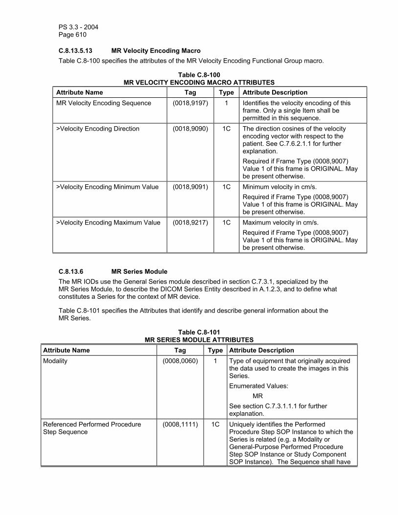
PS 3.3 - 2004 Page 610
C.8.13.5.13 MR Velocity Encoding Macro Table C.8-100 specifies the attributes of the MR Velocity Encoding Functional Group macro.
Table C.8-100 MR VELOCITY ENCODING MACRO ATTRIBUTES
Attribute Name Tag Type Attribute Description MR Velocity Encoding Sequence (0018,9197) 1 Identifies the velocity encoding of this
frame. Only a single Item shall be permitted in this sequence.
>Velocity Encoding Direction (0018,9090) 1C The direction cosines of the velocity encoding vector with respect to the patient. See C.7.6.2.1.1 for further explanation. Required if Frame Type (0008,9007) Value 1 of this frame is ORIGINAL. May be present otherwise.
>Velocity Encoding Minimum Value (0018,9091) 1C Minimum velocity in cm/s. Required if Frame Type (0008,9007) Value 1 of this frame is ORIGINAL. May be present otherwise.
>Velocity Encoding Maximum Value (0018,9217) 1C Maximum velocity in cm/s. Required if Frame Type (0008,9007) Value 1 of this frame is ORIGINAL. May be present otherwise.
C.8.13.6 MR Series Module The MR IODs use the General Series module described in section C.7.3.1, specialized by the MR Series Module, to describe the DICOM Series Entity described in A.1.2.3, and to define what constitutes a Series for the context of MR device.
Table C.8-101 specifies the Attributes that identify and describe general information about the MR Series.
Table C.8-101 MR SERIES MODULE ATTRIBUTES
Attribute Name Tag Type Attribute Description Modality (0008,0060) 1 Type of equipment that originally acquired
the data used to create the images in this Series. Enumerated Values: MR See section C.7.3.1.1.1 for further explanation.
Referenced Performed Procedure Step Sequence
(0008,1111) 1C Uniquely identifies the Performed Procedure Step SOP Instance to which the Series is related (e.g. a Modality or General-Purpose Performed Procedure Step SOP Instance or Study Component SOP Instance). The Sequence shall have

PS 3.3 - 2004 Page 611
one Item. Required if the Modality Performed Procedure Step SOP Class , General Purpose Performed Procedure Step SOP Class or Study Component SOP Class is supported.
>Referenced SOP Class UID (0008,1150) 1 Uniquely identifies the referenced SOP Class.
>Referenced SOP Instance UID (0008,1155) 1 Uniquely identifies the referenced SOP Instance.
C.8.14 MR Spectroscopy Modules This section describes the MR Spectroscopy Modules.
Note: Many attributes have names and descriptions that include the terms “pixel” and “image”. Although MR spectroscopy is not pixel based, some of these “pixel” and “image” attributes encode concepts that are still relevant for this technique. Where such attributes appear in the MR Spectroscopy IOD, it may be helpful to consider the term “pixel” to be equivalent to a spectroscopy “voxel”, and the term “image” to be equivalent to “MR Spectroscopy SOP Instance”.
C.8.14.1 MR Spectroscopy Module Table C.8-102 specifies the attributes of the MR Spectroscopy Module.
Table C.8-102 MR SPECTROSCOPY MODULE ATTRIBUTES
Attribute Name Tag Type Attribute Description
Include ' MR Image and MR Spectroscopy Instance Macro' Table C.8.13-3
Image Type (0008,0008) 1 Spectroscopy data characteristics. See C.8.14.5.1.1.

PS 3.3 - 2004 Page 612
Include 'MR Spectroscopy Description Macro' Table C.8.14-6 Transmitter Frequency (0018,9098) 1C Precession frequency in MHz of the
nucleus being addressed for each spectral axis. See section C.8.14.1.1 for further explanation of the ordering. Required if Image Type (0008,0008) Value 1 is ORIGINAL. May be present otherwise.
Spectral Width (0018,9052) 1C Spectral width in Hz. See section C.8.14.1.1 for further explanation of the ordering. Required if Image Type (0008,0008) Value 1 is ORIGINAL or MIXED. May be present otherwise.
Chemical Shift Reference (0018,9053) 1C The chemical shift at the transmitter frequency in ppm. See section C.8.14.1.1 for further explanation of the ordering. Required if Image Type (0008,0008) Value 1 is ORIGINAL or MIXED. May be present otherwise.
Volume Localization Technique (0018,9054) 1C Name of volume localization technique used. Shall be “NONE” if no spatial localization was performed. Defined Terms: ILOPS ISIS PRIME PRESS SLIM SLOOP STEAM NONE Required if Image Type (0008,0008) Value 1 is ORIGINAL or MIXED. May be present otherwise.
Volume Localization Sequence (0018,9126) 1C A sequence of one or more Items that provide the position of RF excitations used to select a volume of tissue. The selected volume is described by the intersection of the sequence Items. Required if Image Type (0008,0008) Value 1 is ORIGINAL or MIXED and Volume Localization Technique (0018,9054) is other than NONE. May be present if Volume Localization Technique (0018,9054) is other than NONE.
>Slab Thickness (0018,9104) 1 Thickness of slab in mm. >Slab Orientation (0018,9105) 1 The direction cosines of a normal vector

PS 3.3 - 2004 Page 613
perpendicular to the selection plane with respect to the patient. See C.7.6.2.1.1 for further explanation.
>Mid Slab Position (0018,9106) 1 The x, y, and z coordinates of the mid-point of the slab in mm. See C.7.6.2.1.1 for further explanation.
De-coupling (0018,9059) 1C Indicates whether de-coupling was active. Enumerated Values: YES NO Required if Image Type (0008,0008) Value 1 is ORIGINAL or MIXED. May be present otherwise.
De-coupled Nucleus (0018,9060) 1C Nucleus being de-coupled. Defined Terms: 1H 3HE 7LI 13C 19F 23NA 31P 129XE See section C.8.14.1.1 for further explanation of the ordering. Required if De-coupling (0018,9059) equals YES.
De-coupling Frequency (0018,9061) 1C The center frequency (Hz) for the de-coupling. See section C.8.14.1.1 for further explanation of the ordering. Required if De-coupling (0018,9059) equals YES.
De-coupling Method (0018,9062) 1C The de-coupling modulation scheme used. Defined Terms: MLEV WALTZ NARROWBAND Required if De-coupling (0018,9059) equals YES.
De-coupling Chemical Shift Reference
(0018,9063) 1C The chemical shift in ppm at the de-coupling frequency. See section C.8.14.1.1 for further explanation of the ordering. Required if De-coupling (0018,9059) equals YES.
Time Domain Filtering (0018,9065) 1C Describes time domain filtering or apodization applied. Shall be NONE if no

PS 3.3 - 2004 Page 614
filtering operations were applied to the time domain data. Defined Terms: COSINE COSINE_SQUARED EXPONENTIAL GAUSSIAN HAMMING HANNING LORENTZIAN LRNTZ_GSS_TRNSFM NONE See section C.8.14.1.1 for further explanation of the ordering. Required if Image Type (0008,0008) Value 1 is ORIGINAL or MIXED. May be present otherwise.
Number of Zero Fills (0018,9066) 1C Number of zero fills added to the time domain data before FT. Shall be 0 (zero) if no zero filling performed. See section C.8.14.1.1 for further explanation of the ordering. Required if Image Type (0008,0008) Value 1 is ORIGINAL or MIXED. May be present otherwise.
Baseline Correction (0018,9067) 1C Describes baseline correction techniques. Shall be NONE if no baseline correction was performed. Defined Terms: LINEAR_TILT LOCAL_LINEAR_FIT POLYNOMIAL_FIT SINC_DECONVOLUTN TIME_DOMAIN_FIT SPLINE NONE Required if Image Type (0008,0008) Value 1 is ORIGINAL or MIXED. May be present otherwise.
Frequency Correction (0018,9101) 1C Specifies whether operations were performed to correct resonant frequency of metabolite peaks due to B0 field inhomogeneities. Enumerated Values: YES NO Required if Image Type (0008,0008) Value 1 is ORIGINAL or MIXED. May be present otherwise.
First Order Phase Correction (0018,9198) 1C Describes whether a first order (frequency dependent) phase correction was applied to the spectral data.

PS 3.3 - 2004 Page 615
Enumerated Values: YES NO Required if Image Type (0008,0008) Value 1 is ORIGINAL or MIXED. May be present otherwise.
Water Referenced Phase Correction (0018,9199) 1C Enumerated Values: YES NO Required if Image Type (0008,0008) Value 1 is ORIGINAL or MIXED. May be present otherwise.
C.8.14.1.1 MR Spectroscopy Attribute Multiplicity Ordering The following attributes may have a Value Multiplicity of one or two depending whether one or two frequency axes are used as specified by the value of Data Point Rows (0028,9001):
Transmitter Frequency (0018,9098) Resonant Nucleus (0018,9100) Spectral Width (0018,9052) Chemical Shift Reference (0018,9053) De-coupled Nucleus (0018,9060) De-coupling Frequency (0018,9061) De-coupling Chemical Shift Reference (0018,9063) Time Domain Filtering (0018,9065) Number of Zero Fills (0018,9066)
Value 1 shall contain the value corresponding to the sampling time axis (the axis along a data point row).
Value 2, if present, shall contain the value corresponding to the evolution time axis (the axis along a data point column).
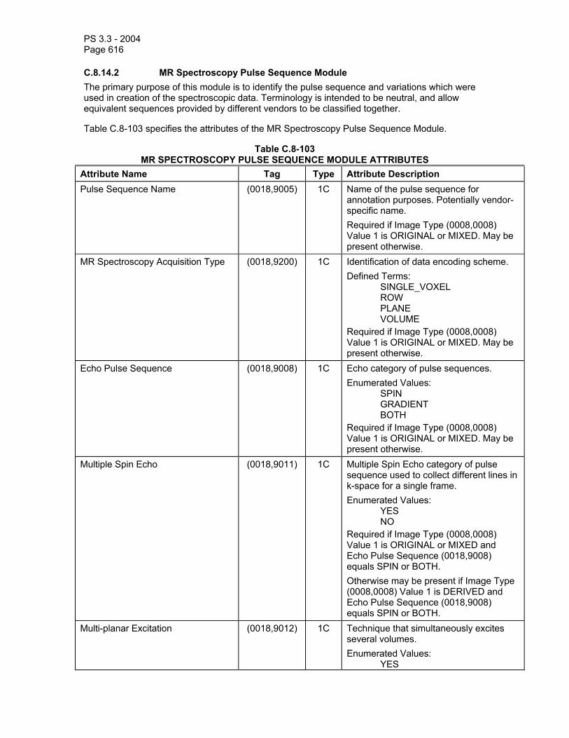
PS 3.3 - 2004 Page 616
C.8.14.2 MR Spectroscopy Pulse Sequence Module The primary purpose of this module is to identify the pulse sequence and variations which were used in creation of the spectroscopic data. Terminology is intended to be neutral, and allow equivalent sequences provided by different vendors to be classified together.
Table C.8-103 specifies the attributes of the MR Spectroscopy Pulse Sequence Module.
Table C.8-103 MR SPECTROSCOPY PULSE SEQUENCE MODULE ATTRIBUTES
Attribute Name Tag Type Attribute Description Pulse Sequence Name (0018,9005) 1C Name of the pulse sequence for
annotation purposes. Potentially vendor-specific name. Required if Image Type (0008,0008) Value 1 is ORIGINAL or MIXED. May be present otherwise.
MR Spectroscopy Acquisition Type (0018,9200) 1C Identification of data encoding scheme. Defined Terms: SINGLE_VOXEL ROW PLANE VOLUME Required if Image Type (0008,0008) Value 1 is ORIGINAL or MIXED. May be present otherwise.
Echo Pulse Sequence (0018,9008) 1C Echo category of pulse sequences. Enumerated Values: SPIN GRADIENT BOTH Required if Image Type (0008,0008) Value 1 is ORIGINAL or MIXED. May be present otherwise.
Multiple Spin Echo (0018,9011) 1C Multiple Spin Echo category of pulse sequence used to collect different lines in k-space for a single frame. Enumerated Values: YES NO Required if Image Type (0008,0008) Value 1 is ORIGINAL or MIXED and Echo Pulse Sequence (0018,9008) equals SPIN or BOTH. Otherwise may be present if Image Type (0008,0008) Value 1 is DERIVED and Echo Pulse Sequence (0018,9008) equals SPIN or BOTH.
Multi-planar Excitation (0018,9012) 1C Technique that simultaneously excites several volumes. Enumerated Values: YES

PS 3.3 - 2004 Page 617
NO Required if Image Type (0008,0008) Value 1 is ORIGINAL or MIXED. May be present otherwise.
Steady State Pulse Sequence (0018,9017) 1C Steady State Sequence. Defined Terms: FREE_PRECESSION TRANSVERSE TIME_REVERSED LONGITUDINAL NONE Required if Image Type (0008,0008) Value 1 is ORIGINAL or MIXED. May be present otherwise.
Echo Planar Pulse Sequence (0018,9018) 1C Echo Planar category of pulse-sequences. Enumerated Values: YES NO Required if Image Type (0008,0008) Value 1 is ORIGINAL or MIXED. May be present otherwise.
Spectrally Selected Suppression (0018,9025) 1C Spectrally Selected Suppression. Defined Terms: WATER FAT FAT_AND_WATER SILICON_GEL NONE Required if Image Type (0008,0008) Value 1 is ORIGINAL or MIXED. May be present otherwise.
Geometry of k-Space Traversal (0018,9032) 1C Geometry category of k-Space traversal. Defined Terms: RECTILINEAR RADIAL SPIRAL Required if Image Type (0008,0008) Value 1 is ORIGINAL or MIXED. May be present otherwise.
Rectilinear Phase Encode Reordering
(0018,9034) 1C Rectilinear phase encode reordering. Defined Terms: LINEAR CENTRIC SEGMENTED REVERSE_LINEAR REVERSE_CENTRIC Required if Required if Image Type (0008,0008) Value 1 is ORIGINAL or MIXED and Geometry of k-Space Traversal (0018,9032) equals

PS 3.3 - 2004 Page 618
RECTILINEAR. Otherwise may be present if Image Type (0008,0008) Value 1 is DERIVED and Geometry of k-Space Traversal (0018,9032) equals RECTILINEAR.
Segmented k-Space Traversal (0018,9033) 1C Segmented k-Space traversal. If Geometry of k-Space Traversal is rectilinear, multiple lines can be acquired at one time. If Geometry of k-Space Traversal is spiral or radial, paths can be interleaved and acquired at one time. Enumerated Values: SINGLE = successive single
echo coverage PARTIAL = segmented
coverage FULL = single shot full
coverage Required if Image Type (0008,0008) Value 1 is ORIGINAL or MIXED. May be present otherwise.
Coverage of k-Space (0018,9094) 1C Coverage of k-Space. Defined Terms: FULL CYLINDRICAL ELLIPSOIDAL WEIGHTED Required if Image Type (0008,0008) Value 1 is ORIGINAL or MIXED and MR Spectroscopy Acquisition Type (0018,9200) equals VOLUME. Otherwise may be present if Image Type (0008,0008) Value 1 is DERIVED and MR Spectroscopy Acquisition Type (0018,9200) equals VOLUME.
Number of k-Space Trajectories (0018,9093) 1C Number of interleaves or shots. Required if Image Type (0008,0008) Value 1 is ORIGINAL or MIXED. May be present otherwise.
C.8.14.3 MR Spectroscopy Functional Group Macros The following sections contain Functional Group Macro's specific to the MR Spectroscopy IOD.
Note: The attribute descriptions in the Functional Group Macros are written as if they were applicable to a single frame (i.e., the macro is part of the Per-frame Functional Groups Sequence). If an attribute is applicable to all frames (i.e. the macro is part of the Shared Functional Groups Sequence) the phrase "this frame" in the attribute description shall be interpreted to mean " for all frames".".

PS 3.3 - 2004 Page 619
C.8.14.3.1 MR Spectroscopy Frame Type Macro Table C.8-104 specifies the attributes of the MR Spectroscopy Frame Type Functional Group macro.
Table C.8-104 MR SPECTROSCOPY FRAME TYPE MACRO ATTRIBUTES
Attribute Name Tag Type Attribute Description MR Spectroscopy Frame Type Sequence
(0018,9227) 1 Identifies sequence containing Frame Type Attributes. Only a single Item shall be permitted in this sequence.
>Frame Type (0008,9007) 1 Spectroscopy data characteristics. See C.8.14.5.1.1.
>Include 'MR Spectroscopy Description Macro' Table C.8.14-6
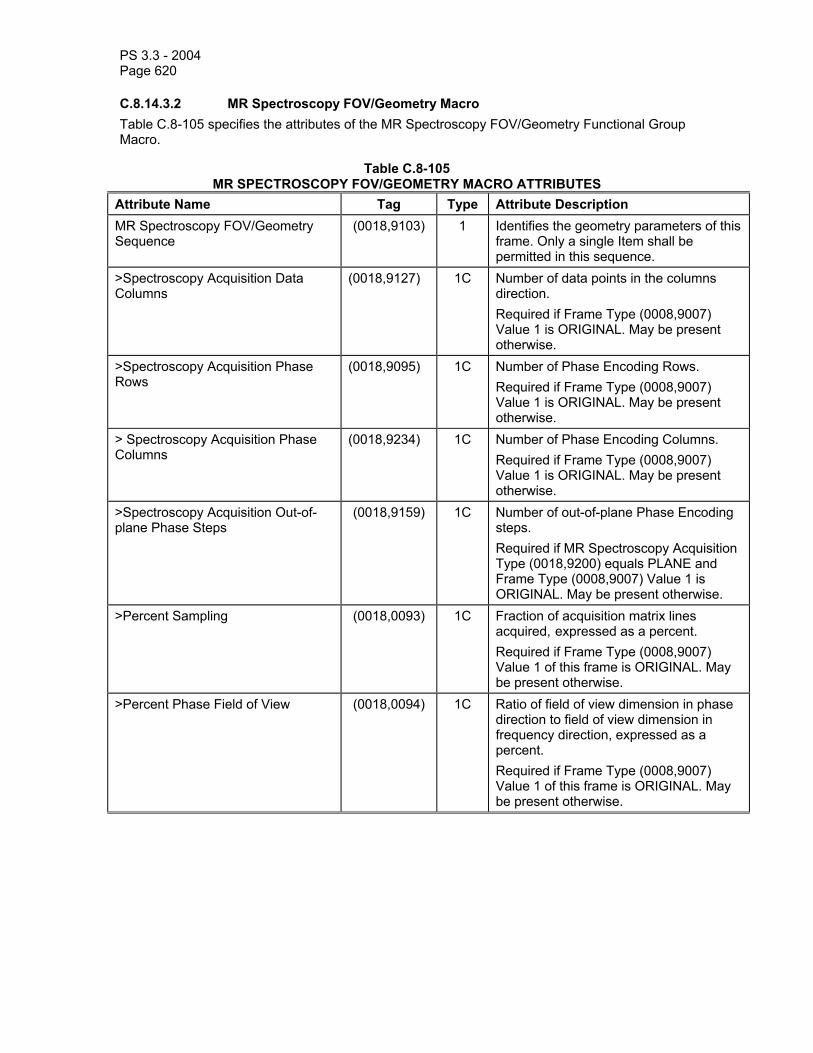
PS 3.3 - 2004 Page 620
C.8.14.3.2 MR Spectroscopy FOV/Geometry Macro Table C.8-105 specifies the attributes of the MR Spectroscopy FOV/Geometry Functional Group Macro.
Table C.8-105 MR SPECTROSCOPY FOV/GEOMETRY MACRO ATTRIBUTES
Attribute Name Tag Type Attribute Description MR Spectroscopy FOV/Geometry Sequence
(0018,9103) 1 Identifies the geometry parameters of this frame. Only a single Item shall be permitted in this sequence.
>Spectroscopy Acquisition Data Columns
(0018,9127) 1C Number of data points in the columns direction. Required if Frame Type (0008,9007) Value 1 is ORIGINAL. May be present otherwise.
>Spectroscopy Acquisition Phase Rows
(0018,9095) 1C Number of Phase Encoding Rows. Required if Frame Type (0008,9007) Value 1 is ORIGINAL. May be present otherwise.
> Spectroscopy Acquisition Phase Columns
(0018,9234) 1C Number of Phase Encoding Columns. Required if Frame Type (0008,9007) Value 1 is ORIGINAL. May be present otherwise.
>Spectroscopy Acquisition Out-of-plane Phase Steps
(0018,9159) 1C Number of out-of-plane Phase Encoding steps. Required if MR Spectroscopy Acquisition Type (0018,9200) equals PLANE and Frame Type (0008,9007) Value 1 is ORIGINAL. May be present otherwise.
>Percent Sampling (0018,0093) 1C Fraction of acquisition matrix lines acquired, expressed as a percent. Required if Frame Type (0008,9007) Value 1 of this frame is ORIGINAL. May be present otherwise.
>Percent Phase Field of View (0018,0094) 1C Ratio of field of view dimension in phase direction to field of view dimension in frequency direction, expressed as a percent. Required if Frame Type (0008,9007) Value 1 of this frame is ORIGINAL. May be present otherwise.

PS 3.3 - 2004 Page 621
C.8.14.4 MR Spectroscopy Data Module Table C.8-106 specifies the attributes that describe the Spectroscopy Data.
Table C.8-106 MR SPECTROSCOPY DATA MODULE ATTRIBUTES
Attribute Name Tag Type Attribute Description Rows (0028,0010) 1 Number of voxels in the vertical direction
in the frame. Columns (0028,0011) 1 Number of voxels in the horizontal
direction in the frame. Data Point Rows (0028,9001) 1 Number of rows of data points in
spectroscopic data. Data Point Columns (0028,9002) 1 Number of columns of data points in
spectroscopic data. Data Representation (0028,9108) 1 Data representation of the data points.
Each data point shall have the same representation. Enumerated Values:
COMPLEX = Data is complex pair
REAL = Data contains only real component
IMAGINARY = Data contains only imaginary component
MAGNITUDE = Magnitude data Signal Domain Columns (0028,9003) 1 Domain of represented signal in column
direction. Enumerated Values: FREQUENCY TIME
Signal Domain Rows (0028,9235) 1C Domain of represented signal in row direction. Enumerated Values: FREQUENCY TIME Required if Data Point Rows (0028,9001) has a value of more than 1.
First Order Phase Correction Angle (5600,0010) 1C First Order Phase Correction Angle. Number of values is determined by Row ∗ Column ∗ Number of Frames. Required if First Order Phase Correction (0018,9198) equals YES
Spectroscopy Data (5600,0020) 1 A data stream of the signal intensities that comprise the spectroscopic data. See C.8.14.4.1 for further explanation.

PS 3.3 - 2004 Page 622
C.8.14.4.1 Spectroscopy Data The Spectroscopy Data attribute (5600,0020) contains the Signal intensities for the spectra. The order of voxels sent for each spectral plane is left to right, top to bottom, i.e., the upper left voxel (labeled 1,1) is sent first followed by the remainder of row 1, followed by the first voxel of row 2 (labeled 2,1) then the remainder of row 2 and so on. Each "voxel" represents an entire spectrum. The complete spectral data from each voxel is sent, followed by the spectral data from the next voxel position.
The number of voxels on each frame are described by Rows (0028,0010) and Columns (0028,0011). The number of frames is described by Number of Frames (0028,0008). The frames may represent different locations in a 3D acquisition, or the same position at a different point of time, or a difference of some other combination of attributes.
The spectral data points are ordered from lower effective magnetic field strength (down-field) to higher effective magnetic field strength (up-field) when the Signal Domain Columns (0028,9003) or Signal Domain Rows (0028,9235) attributes contain the value FREQUENCY and from first sample acquired to last sample acquired when the Signal Domain Columns (0028,9003) or Signal Domain Rows (0028,9235) attributes contain the value TIME.
For two-dimensional spectral acquisitions, the ordering is such that all data points from a row (corresponding to all data points acquired in an individual sampling period), are followed by all data points from the successive sampling period. Following all data of the rows from a given voxel position, the data from the subsequent voxel position are sent. The axis parallel to the row direction corresponds to the sampling time axis. The axis parallel to the column direction corresponds to the evolution time axis.
The dimensions of each spectrum that make up a voxel are described by Data Point Rows (0028,9001) and Data Point Columns (0028,9002). In the case of 1D spectra, the number of Data Point Rows shall be 1.
For a Data Representation (0028,9108) value of COMPLEX, the order of data points is real channel followed by imaginary channel for each spectral data point. For the other Data Representation values (REAL, IMAGINARY and MAGNITUDE), each spectral data point contains only a single value.
The Figure C.8-18 depicts 6 frames each made up of 4 rows and 4 columns of voxels. Specific values for Data Point Rows (0028,9001) and Data Point Columns (0028,9002) of these voxels are not depicted.

PS 3.3 - 2004 Page 623
Frames
Data Point
Columns
Data Point Rows
Rows
Columns
Figure C.8-18 Dimensions of spectroscopy data.
C.8.14.5 MR Spectroscopy Description Macro Table C.8-107 specifies the attributes that describe the Spectroscopy.
Table C.8-107 MR SPECTROSCOPY DESCRIPTION MACRO ATTRIBUTES
Attribute Name Tag Type Attribute Description Volumetric Properties (0008,9206) 1 Indication if geometric manipulations are
possible with frames in the SOP Instance. See C.8.14.5.1.2 for a description and Enumerated Values.
Volume Based Calculation Technique
(0008,9207) 1 Method used for volume calculations with frames in the SOP Instance. See C.8.14.5.1.3 for a description and Defined Terms.
Complex Image Component (0008,9208) 1 Representation of complex data of frames in the SOP Instance. See C.8.14.5.1.4 for a description and Defined Terms.

PS 3.3 - 2004 Page 624
Acquisition Contrast (0008,9209) 1 Indication of acquisition contrast used with frames in the SOP Instance. See C.8.14.5.1.5 for a description and Defined Terms.
C.8.14.5.1 MR Spectroscopy Description Attribute Description C.8.14.5.1.1 Image Type and Frame Type The Image Type (0008,0008) and Frame Type (0008,9007) are not included in this Macro but one or the other is always included in the Module or Macro that invokes this Macro, and they are therefore described here.
In addition to the requirements specified in C.8.16.1 Image Type and Frame Type, the following additional requirements and Defined Terms are specified.
C.8.14.5.1.1.1 Pixel Data Characteristics See C.8.16.1.1. No additional requirements or Defined Terms.
C.8.14.5.1.1.2 Patient Examination Characteristics See C.8.16.1.2. No additional requirements or Defined Terms.
C.8.14.5.1.1.3 Image Flavor See C.8.16.1.3 for requirements, but not Defined Terms.
Table C.8-108 specifies the Defined Terms for MR Spectroscopy for Value 3 for Image Type (0008,0008) and Frame Type (0008,9007).
Table C.8-108 MR SPECTROSCOPY IMAGE TYPE AND FRAME TYPE VALUE 3
Defined Term Name Defined Term Description SPECTROSCOPY Spectroscopy
C.8.14.5.1.1.4 Derived Pixel Contrast See C.8.16.1.4 for requirements, but not Defined Terms.

PS 3.3 - 2004 Page 625
Table C.8-109 specifies the Defined Terms for Value 4 for Image Type (0008,0008) and Frame Type (0008,9007).
Table C.8-109 MR SPECTROSCOPY IMAGE TYPE AND FRAME TYPE VALUE 4
Defined Term Name Defined Term Description ADDITION Created through point by point addition operation DIVISION Created through point by point division operation MAXIMUM Created through point by point maximum operation MEAN Created through point by point mean operation MINIMUM Created through point by point minimum operation MULTIPLICATION Created through point by point multiplication operation STD_DEVIATION Standard Deviation SUBTRACTION Created through point by point subtraction operation NONE Not calculated MIXED Used only as value in Image Type (0008,0008) if frames
within the spectroscopy SOP Instance contain different values for value 4 in their Frame Type (0008,9007) attribute.
C.8.14.5.1.2 Volumetric Properties See C.8.16.2.1.2. No additional requirements or Defined Terms.
C.8.14.5.1.3 Volume Based Calculation Technique Attribute See C.8.16.2.1.3 for requirements, but not Defined Terms.
Table C.8-110 specifies the Defined Terms for the Volume Based Calculation Technique (0008,9207) attribute.
Table C.8-110 VOLUME BASED CALCULATION TECHNIQUE ATTRIBUTE VALUES
Defined Term Name Defined Term Description MAX_IP Maximum Intensity Projection MIN_IP Minimum Intensity Projection NONE Pixels not derived geometrically MIXED Used only as a value in Volume Based Calculation
Technique (0008,9207) attribute in the MR Spectroscopy Module if frames within the image SOP Instance contain different terms for the Volume Based Calculation Technique attribute in MR Spectroscopy Frame Type Functional Group.

PS 3.3 - 2004 Page 626
C.8.14.5.1.4 Complex Image Component The value of the Complex Image Component attribute (0008,9208) shall be used to indicate which component of the complex representation of the signal is represented in the spectroscopy data.
Table C.8-111 specifies the Defined Terms for Complex Image Component attribute (0008,9208).
Table C.8-111 COMPLEX IMAGE COMPONENT ATTRIBUTE VALUES
Defined Term Name Defined Term Description MAGNITUDE The magnitude component of the complex spectroscopy
data. PHASE The phase component of the complex spectroscopy data. REAL The real component of the complex spectroscopy data. IMAGINARY The imaginary component of the complex spectroscopy data.COMPLEX The real and imaginary components of the complex
spectroscopy data MIXED Used only as a value in Complex Image Component
(0008,9208) in the MR Spectroscopy Module if frames within the image SOP Instance contain different values for the Complex Image Component attribute in the MR Spectroscopy Frame Type Functional Group.
C.8.14.5.1.5 Acquisition Contrast Table C.8-112 specifies the Defined Terms for Acquisition Contrast attribute (0008,9209).
Table C.8-112 ACQUISITION CONTRAST VALUES
Defined Term Name Defined Term Description PROTON_DENSITY Proton Density weighted contrast T1 T1 weighted contrast T2 T2 weighted contrast UNKNOWN Value should be UNKNOWN if acquisition contrasts were
combined resulting in an unknown contrast. Also this value should be used when the contrast is not known.
MIXED Used only as a value in Acquisition Contrast (0008,9209) attribute in the MR Spectroscopy Module if frames within the SOP Instance contain different values for the Acquisition Contrast attribute in the MR Spectroscopy Frame Type Functional Group.
C.8.15 Enhanced CT Image This section describes the specific modules for the Enhanced CT Image IOD.
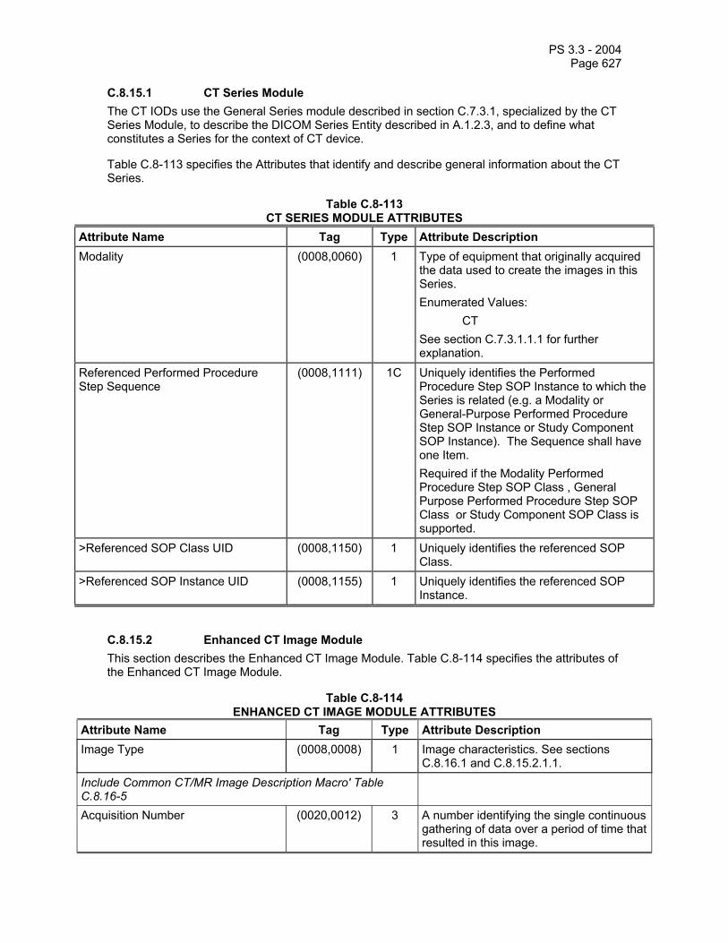
PS 3.3 - 2004 Page 627
C.8.15.1 CT Series Module The CT IODs use the General Series module described in section C.7.3.1, specialized by the CT Series Module, to describe the DICOM Series Entity described in A.1.2.3, and to define what constitutes a Series for the context of CT device.
Table C.8-113 specifies the Attributes that identify and describe general information about the CT Series.
Table C.8-113 CT SERIES MODULE ATTRIBUTES
Attribute Name Tag Type Attribute Description Modality (0008,0060) 1 Type of equipment that originally acquired
the data used to create the images in this Series. Enumerated Values: CT See section C.7.3.1.1.1 for further explanation.
Referenced Performed Procedure Step Sequence
(0008,1111) 1C Uniquely identifies the Performed Procedure Step SOP Instance to which the Series is related (e.g. a Modality or General-Purpose Performed Procedure Step SOP Instance or Study Component SOP Instance). The Sequence shall have one Item. Required if the Modality Performed Procedure Step SOP Class , General Purpose Performed Procedure Step SOP Class or Study Component SOP Class is supported.
>Referenced SOP Class UID (0008,1150) 1 Uniquely identifies the referenced SOP Class.
>Referenced SOP Instance UID (0008,1155) 1 Uniquely identifies the referenced SOP Instance.
C.8.15.2 Enhanced CT Image Module This section describes the Enhanced CT Image Module. Table C.8-114 specifies the attributes of the Enhanced CT Image Module.
Table C.8-114 ENHANCED CT IMAGE MODULE ATTRIBUTES
Attribute Name Tag Type Attribute Description Image Type (0008,0008) 1 Image characteristics. See sections
C.8.16.1 and C.8.15.2.1.1. Include Common CT/MR Image Description Macro' Table C.8.16-5
Acquisition Number (0020,0012) 3 A number identifying the single continuous gathering of data over a period of time that resulted in this image.
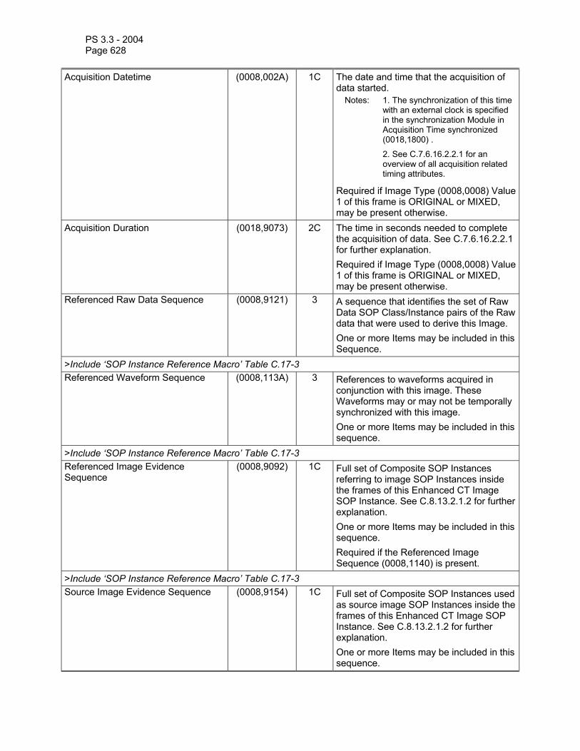
PS 3.3 - 2004 Page 628
Acquisition Datetime (0008,002A) 1C The date and time that the acquisition of data started.
Notes: 1. The synchronization of this time with an external clock is specified in the synchronization Module in Acquisition Time synchronized (0018,1800) .
2. See C.7.6.16.2.2.1 for an overview of all acquisition related timing attributes.
Required if Image Type (0008,0008) Value 1 of this frame is ORIGINAL or MIXED, may be present otherwise.
Acquisition Duration (0018,9073) 2C The time in seconds needed to complete the acquisition of data. See C.7.6.16.2.2.1 for further explanation. Required if Image Type (0008,0008) Value 1 of this frame is ORIGINAL or MIXED, may be present otherwise.
Referenced Raw Data Sequence (0008,9121) 3 A sequence that identifies the set of Raw Data SOP Class/Instance pairs of the Raw data that were used to derive this Image. One or more Items may be included in this Sequence.
>Include ‘SOP Instance Reference Macro’ Table C.17-3 Referenced Waveform Sequence (0008,113A) 3 References to waveforms acquired in
conjunction with this image. These Waveforms may or may not be temporally synchronized with this image. One or more Items may be included in this sequence.
>Include ‘SOP Instance Reference Macro’ Table C.17-3 Referenced Image Evidence Sequence
(0008,9092) 1C Full set of Composite SOP Instances referring to image SOP Instances inside the frames of this Enhanced CT Image SOP Instance. See C.8.13.2.1.2 for further explanation. One or more Items may be included in this sequence. Required if the Referenced Image Sequence (0008,1140) is present.
>Include ‘SOP Instance Reference Macro’ Table C.17-3 Source Image Evidence Sequence (0008,9154) 1C Full set of Composite SOP Instances used
as source image SOP Instances inside the frames of this Enhanced CT Image SOP Instance. See C.8.13.2.1.2 for further explanation. One or more Items may be included in this sequence.

PS 3.3 - 2004 Page 629
Required if the Source Image Sequence (0008,2112) is present.
>Include ‘SOP Instance Reference Macro’ Table C.17-3 Referenced Grayscale Presentation State Sequence
(0008,9237) 1C References to Grayscale Presentation State instances acquired in conjunction with this instance.
Note: May only be used to reference Presentation States belonging to the acquired data and not to reference Presentation States generated subsequently such as during interpretation.
One or more Items may be included in this sequence. Required if Presentation State is generated during acquisition, shall not be present otherwise.
>Include 'SOP Instance Reference Macro' Table C.17-3 Samples per Pixel (0028,0002) 1 Number of samples (planes) in this image.
This value shall be 1. Photometric Interpretation (0028,0004) 1 Specifies the intended interpretation of the
pixel data. Enumerated Value: MONOCHROME2. See C.7.6.3.1.2 for definition of this term.
Bits Allocated (0028,0100) 1 Number of bits allocated for each pixel sample. Each sample shall have the same number of bits allocated. This value shall be 16.
Bits Stored (0028,0101) 1 Number of bits stored for each pixel sample. Each sample shall have the same number of bits stored. This value shall be 12 or16.
High Bit (0028,0102) 1 Most significant bit for pixel sample data. Each sample shall have the same high bit. Shall be one less than the value in Bits Stored (0028,0101).
Content Qualification (0018,9004) 1 Content Qualification Indicator Enumerated Values: PRODUCT RESEARCH SERVICE See C.8.13.2.1.1 for further explanation.
Image Comments (0020,4000) 3 User-defined comments about the image Lossy Image Compression (0028,2110) 1 Specifies whether an Image has
undergone lossy compression. Enumerated Values: 00 = Image has NOT been subjected to lossy compression.
01 = Image has been subjected to lossy

PS 3.3 - 2004 Page 630
compression.
See C.7.6.1.1.5 for further explanation. Lossy Image Compression Ratio (0028,2112) 1C Describes the approximate lossy
compression ratio(s) that have been applied to this image. See C.7.6.1.1.5 for further explanation. May be multivalued if successive lossy compression steps have been applied.
Note: For example, a compression ratio of 30:1 would be described in this Attribute with a single value of 30.
Required if Lossy Images Compression (0028,2110) is “01”.
Icon Image Sequence (0088,0200) 3 This icon image is representative of the Image.
> Include ‘Image Pixel Macro’ Table C.7-11b See Section F.7.
C.8.15.2.1 CT Image Description Attribute Description C.8.15.2.1.1 Image Type and Frame Type In addition to the requirements specified in C.8.16.1 Image Type and Frame Type, the following additional requirements and Defined Terms are specified.
These requirements and Defined Terms are also applicable to Frame Type (0008,9007).
C.8.15.2.1.1.1 Pixel Data Characteristics Value 1 of Image Type (0008,0008) and Frame Type (0008,9007) is discussed in C.8.16.1.1. No additional requirements or Defined Terms.
C.8.15.2.1.1.2 Patient Examination Characteristics Value 2 of Image Type (0008,0008) and Frame Type (0008,9007) is discussed in C.8.16.1.2. No additional requirements or Defined Terms.
C.8.15.2.1.1.3 Image Flavor Table C.8-115 specifies the Defined Terms for CT additional to those defined in C.8.16.1.3 for Value 3 for Image Type (0008,0008) and Frame Type (0008,9007).
Table C.8-115 IMAGE TYPE AND FRAME TYPE VALUE 3 FOR CT
Defined Term Name Defined Term Description ATTENUATION Collected for the purpose of performing attenuation
corrections (e.g. PET attenuation correction) CARDIAC Cardiac images CARDIAC_GATED Cardiac gated images REFERENCE Collected for anatomical reference for PET or SPECT

PS 3.3 - 2004 Page 631
C.8.15.2.1.1.4 Derived Pixel Contrast Table C.8-116 specifies the Defined Terms for CT additional to those defined in C.8.16.1.4 for Value 4 for Image Type (0008,0008) and Frame Type (0008,9007).
Table C.8-116 IMAGE TYPE AND FRAME TYPE VALUE 4 FOR CT
Defined Term Name Defined Term Description FILTERED An image filter has been applied MEDIAN Pixel by pixel median
C.8.15.3 Enhanced CT Image Functional Group Macros The following sections contain Functional Group macros specific to the Enhanced CT Image IOD.
Note: The attribute descriptions in the Functional Group Macros are written as if they were applicable to a single frame (i.e., the macro is part of the Per-frame Functional Groups Sequence). If an attribute is applicable to all frames (i.e. the macro is part of the Shared Functional Groups Sequence) the phrase "this frame" in the attribute description shall be interpreted to mean " for all frames".
C.8.15.3.1 CT Image Frame Type Macro Table C.8-117 specifies the attributes of the CT Image Frame Type Functional Group macro.
Table C.8-117 CT IMAGE FRAME TYPE MACRO ATTRIBUTES
Attribute Name Tag Type Attribute Description CT Image Frame Type Sequence (0018,9329) 1 Identifies the characteristics of this frame.
Only a single Item shall be permitted in this sequence.
>Frame Type (0008,9007) 1 Type of Frame. A multi-valued attribute analogous to the Image Type (0008,0008). Enumerated Values and Defined Terms are the same as those for the four values of the Image Type (0008,0008) attribute, except that the value MIXED is not allowed. See sections C.8.16.1 and C.8.15.2.1.1.1.
> Include Common CT/MR Image Description Macro' Table C.8.16-5
C.8.15.3.2 CT Acquisition Type Macro Table C.8-118 specifies the attributes of the CT Acquisition Type Functional Group macro.
Table C.8-118 CT ACQUISITION TYPE MACRO ATTRIBUTES
Attribute Name Tag Type Attribute Description CT Acquisition Type Sequence (0018,9301) 1 Contains the attributes defining the CT
acquisition mode. Only a single Item shall

PS 3.3 - 2004 Page 632
be permitted in this sequence. >Acquisition Type (0018,9302) 1C Description of the method used during
acquisition of this frame. See C.8.15.3.2.1 for Defined Terms. Required if Frame Type (0008,9007) Value 1 of this frame is ORIGINAL. May be present otherwise.
>Tube Angle (0018,9303) 1C The constant angle at which the x-ray source is located during acquisition. 0 degrees means that the source is located at the highest point of the gantry orbit. Degrees increase from 0 to positive 360 in a clockwise direction as viewed when facing the gantry where the table enters the gantry. Required if Frame Type (0008,9007) Value 1 of this frame is ORIGINAL and Acquisition Type (0018,9302) is CONSTANT_ANGLE. May be present otherwise if Frame Type (0008,9007) Value 1 of this frame is DERIVED and Acquisition Type (0018,9302) is CONSTANT_ANGLE.
>Constant Volume Flag (0018,9333) 1C Identifies that the acquisition was performed by repetitively acquiring the same volume set over a period of time.
Note: The Acquisition Type (0018,9302) value may be SEQUENCED, SPIRAL or STATIONARY depending on whether table movement is necessary to cover the volume.
Enumerated Values YES NO Required if Frame Type (0008,9007) Value 1 of this frame is ORIGINAL. May be present otherwise.
>Fluoroscopy Flag (0018,9334) 1C Identifies that near real-time display of a block of continuously acquired data was performed, which may result in a lower than usual image quality. Enumerated Values YES NO Required if Frame Type (0008,9007) Value 1 of this frame is ORIGINAL. May be present otherwise.
C.8.15.3.2.1 Acquisition Type

PS 3.3 - 2004 Page 633
Acquisition Type (0018,9302)) has the following Defined Terms:
SEQUENCED identifies that the acquisition was performed by acquiring single or multi detector data while rotating the source about the gantry while the table is not moving. Additional slices are acquired by incrementing the table position and again rotating the source about the gantry while the table is not moving.
SPIRAL identifies that the acquisition was performed by acquiring data while rotating the source about the gantry while continuously moving the table.
CONSTANT_ANGLE identifies that the acquisition was performed by holding the source at a constant angle and moving the table to obtain a projection image (e.g., a localizer image).
STATIONARY identifies that the acquisition was performed by holding the table at a constant position and acquiring multiple slices over time at the same location.
FREE identifies that the acquisition was performed while rotating the source about the gantry while the table movement is under direct control of a human operator or under the control of an analysis application (e.g., fluoroscopic image).
C.8.15.3.3 CT Acquisition Details Macro Table C.8-119 specifies the attributes of the CT Acquisition Details Functional Group macro.
Table C.8-119 CT ACQUISITION DETAILS MACRO ATTRIBUTES
Attribute Name Tag Type Attribute Description CT Acquisition Details Sequence (0018,9304) 1 Contains the attributes defining the
details of the acquisition. Only a single Item shall be permitted in this sequence.
>Rotation Direction (0018,1140) 1C Direction of rotation of the source about the gantry, as viewed while facing the gantry where the table enters the gantry. Enumerated Values: CW = clockwise CC = counter clockwise Required if Frame Type (0008,9007) Value 1 of this frame is ORIGINAL and Acquisition Type (0018,9302) is other than CONSTANT_ANGLE. Otherwise may be present if Frame Type (0008,9007) Value 1 of this frame is DERIVED and Acquisition Type (0018,9302) is other than CONSTANT_ANGLE.
>Revolution Time (0018,9305) 1C The time in seconds of a complete revolution of the source around the gantry orbit. This value is independent of the Reconstruction Angle (0018,9319) of

PS 3.3 - 2004 Page 634
the frame. Required if Frame Type (0008,9007) Value 1 of this frame is ORIGINAL and Acquisition Type (0018,9302) is other than CONSTANT_ANGLE. Otherwise may be present if Frame Type (0008,9007) Value 1 of this frame is DERIVED and Acquisition Type (0018,9302) is other than CONSTANT_ANGLE.
>Single Collimation Width (0018,9306) 1C The width of a single row of acquired data (in mm).
Note: Adjacent physical detector rows may have been combined to form a single effective acquisition row.
Required if Frame Type (0008,9007) Value 1 of this frame is ORIGINAL. May be present otherwise.
>Total Collimation Width (0018,9307) 1C The width of the total collimation (in mm) over the area of active x-ray detection.
Note: This will be equal to the number of effective detector rows multiplied by single collimation width.
Required if Frame Type (0008,9007) Value 1 of this frame is ORIGINAL. May be present otherwise.
>Table Height (0018,1130) 1C The distance in mm from the top of the patient table to the center of rotation of the source (i.e. the data collection center or isocenter). The distance is positive when the table is below the data collection center. Required if Frame Type (0008,9007) Value 1 of this frame is ORIGINAL. May be present otherwise.
>Gantry/Detector Tilt (0018,1120) 1C Nominal angle of tilt in degrees of the scanning gantry. Not intended for mathematical computations. Zero degrees means the gantry is not tilted, negative degrees are when the top of the gantry is tilted away from where the table enters the gantry. Required if Frame Type (0008,9007) Value 1 of this frame is ORIGINAL. May be present otherwise.
>Data Collection Diameter (0018,0090) 1C The diameter in mm of the region over which data were collected. See C.8.15.3.6.1.
Note: In the case of an Acquisition Type (0018,9302) of CONSTANT_ANGLE, the

PS 3.3 - 2004 Page 635
diameter is that in a plane normal to the central ray of the diverging X-ray beam as it passes through the data collection center.
Required if Frame Type (0008,9007) Value 1 of this frame is ORIGINAL. May be present otherwise.
C.8.15.3.4 CT Table Dynamics Macro Table C.8-120 specifies the attributes of the CT Table Dynamics Functional Group macro.
Table C.8-120 CT TABLE DYNAMICS MACRO ATTRIBUTES
Attribute Name Tag Type Attribute Description CT Table Dynamics Sequence (0018,9308) 1 Contains the attributes defining the
movement of the CT table. Only a single Item shall be permitted in this sequence.
>Table Speed (0018,9309) 1C The distance in mm that the table moves in one second during the gathering of data that resulted in this frame. Required if Frame Type (0008,9007) Value 1 of this frame is ORIGINAL and Acquisition Type (0018,9302) is SPIRAL or CONSTANT_ANGLE. May be present otherwise if Frame Type (0008,9007) Value 1 of this frame is DERIVED and Acquisition Type (0018,9302) is SPIRAL or CONSTANT_ANGLE.
>Table Feed per Rotation (0018,9310) 1C Motion of the table (in mm) during a complete revolution of the source around the gantry orbit. Required if Frame Type (0008,9007) Value 1 of this frame is ORIGINAL and Acquisition Type (0018,9302) is SPIRAL. May be present otherwise if Frame Type (0008,9007) Value 1 of this frame is DERIVED and Acquisition Type (0018,9302) is SPIRAL.
>Spiral Pitch Factor (0018,9311) 1C Ratio of the Table Feed per Rotation (0018,9310) to the Total Collimation Width (0018,9307). See C.8.15.3.4.1 for further explanation and some examples. Required if Frame Type (0008,9007) Value 1 of this frame is ORIGINAL and Acquisition Type (0018,9302) is SPIRAL. May be present otherwise if Frame Type (0008,9007) Value 1 of this frame is DERIVED and Acquisition Type

PS 3.3 - 2004 Page 636
(0018,9302) is SPIRAL.
C.8.15.3.4.1 Spiral Pitch Factor The formula for Spiral Pitch Factor (0018,9311) in terms of Table Feed per Rotation (0018,9310) and Total Collimation Width (0018,9307) is:
Spiral Pitch Factor = (Table Feed per Rotation (mm))/(Total Collimation Width (mm))
An example calculation of Spiral Pitch Factor (0018,9311) for a single slice spiral acquisition of an image with a Total Collimation Width of 2.5mm and a Table Feed per Rotation of 10mm is:
Spiral Pitch Factor = (10 mm)/(2.5 mm) = 4.0
An example calculation of Spiral Pitch Factor (0018,9311) for a multiple slice spiral acquisition having a Total Collimation Width of 20mm and a Table Feed per Rotation of 10mm is:
Spiral Pitch Factor = (10 mm)/(20 mm) = 0.5
C.8.15.3.5 CT Position Macro Table C.8-121 specifies the attributes of the CT Position Functional Group macro.
Table C.8-121 CT POSITION MACRO ATTRIBUTES
Attribute Name Tag Type Attribute Description CT Position Sequence (0018,9326) 1 Contains the attributes defining the CT
geometry. Only a single Item shall be permitted in this sequence.
>Table Position (0018,9327) 1C Relative longitudinal position of acquisition location of this frame in mm from an implementation specific reference point. Shall be relative to the same reference point for all frames in this SOP Instance, but may be different from the reference point in other SOP Instances. Positions as the table moves into the gantry viewed from the front are more negative.
Notes: 1. For contiguous slices reconstructed from multiple detectors one would expect different values for adjacent slices.
2. Lateral positioning or tilting or swiveling are not described.
Required if Frame Type (0008,9007) Value 1 of this frame is ORIGINAL. May be present otherwise.
>Data Collection Center (Patient)
(0018,9313) 1C The x, y, and z coordinates (in the patient coordinate system) in mm of the center of the region in which data were collected. See C.8.15.3.6.1. Required if Frame Type (0008,9007)

PS 3.3 - 2004 Page 637
Value 1 of this frame is ORIGINAL. May be present otherwise.
>Reconstruction Target Center (Patient)
(0018,9318) 1C The x, y, and z coordinates (in the patient coordinate system) of the reconstruction center target point as used for reconstruction in mm. See C.8.15.3.6.1.
Note: It the reconstructed image is not magnified or panned the value corresponds with the Data Collection Center (0018,9313) attribute.
Required if Frame Type (0008,9007) Value 1 of this frame is ORIGINAL. May be present otherwise.
C.8.15.3.6 CT Geometry Macro Table C.8-122 specifies the attributes of the CT Geometry Functional Group macro.
Table C.8-122 CT GEOMETRY MACRO ATTRIBUTES
Attribute Name Tag Type Attribute Description CT Geometry Sequence (0018,9312) 1 Contains the attributes defining the CT
geometry. Only a single Item shall be permitted in this sequence.
>Distance Source to Detector (0018,1110) 1C Distance in mm from source to detector center. See C.8.15.3.6.1.
Note: This value is traditionally referred to as Source Image Receptor Distance (SID).
Required if Frame Type (0008,9007) Value 1 of this frame is ORIGINAL. May be present otherwise.
>Distance Source to Data Collection Center
(0018,9335) 1C Distance in mm from source to data collection center. See C.8.15.3.6.1. Required if Frame Type (0008,9007) Value 1 of this frame is ORIGINAL. May be present otherwise.
C.8.15.3.6.1 Relationships Between CT Geometric Attributes (Informative) In Figure C.8-19 the relationship of the Geometric Attributes within the CT Geometry and CT Reconstruction functional groups is shown. The figure, viewed from the front of the gantry (where the table enters the gantry), is informative only and is not meant to represent a standardization of an equipment-based frame of reference.

PS 3.3 - 2004 Page 638
Data Collection Diameter
Distance Source to Data Collection Center
Scan Field
Detector System
Scan Angle = 0 Positive in CW direction
Distance Sourceto Detector
+ -
Gantry Tilt
Reconstruction Target (width)
Reconstruction Target (height)
X-Ray Source
Data Collection Center
Reconstruction Target Center x y z
Reconstruction Diameter
Shaded area is image pixel data
Figure C.8-19: Geometry of CT Acquisition System
C.8.15.3.7 CT Reconstruction Macro Table C.8-123 specifies the attributes of the CT Reconstruction Functional Group macro.
Table C.8-123 CT RECONSTRUCTION MACRO ATTRIBUTES
Attribute Name Tag Type Attribute Description CT Reconstruction Sequence (0018,9314) 1 Contains the attributes holding
information about the reconstruction techniques used. Only a single Item shall be permitted in this sequence.
>Reconstruction Algorithm (0018,9315) 1C Description of the algorithm used when reconstructing the image from the data acquired during the acquisition process. Defined Terms:

PS 3.3 - 2004 Page 639
FILTER_BACK_PROJ ITERATIVE Required if Frame Type (0008,9007) Value 1 of this frame is ORIGINAL. May be present otherwise.
>Convolution Kernel (0018,1210) 1C A label describing the convolution kernel or algorithm used to reconstruct the data. Required if Frame Type (0008,9007) Value 1 of this frame is ORIGINAL. May be present otherwise.
>Convolution Kernel Group (0018,9316) 1C A label describing the group that the Convolution Kernel (0018,1210) belongs. Defined Terms:
BRAIN SOFT_TISSUE LUNG BONE CONSTANT_ANGLE
Required if Convolution Kernel (0018,1210) is present. May be present otherwise.
>Reconstruction Diameter (0018,1100) 1C The diameter in mm of the region from which data were used in creating the reconstruction of the image. Data may exist outside this region and portions of the patient may exist outside this region. See C.8.15.3.6.1. Required if Frame Type (0008,9007) Value 1 of this frame is ORIGINAL, may not be present if Reconstruction Field of View (0018,9317) is present. Otherwise may be present if Frame Type (0008,9007) Value 1 of this frame is ORIGINAL and Reconstruction Field of View (0018,9317) is not present.
>Reconstruction Field of View (0018,9317) 1C The field of view width (x-dimension) followed by height (y-dimension) as used for reconstruction in mm. Required if Frame Type (0008,9007) Value 1 of this frame is ORIGINAL, may not be present if Reconstruction Diameter (0018,1100) is present.
>Reconstruction Pixel Spacing (0018,9322) 1C Physical distance in the patient between the center of each reconstructed pixel, specified by a numeric pair – adjacent row spacing (delimiter) adjacent column spacing in mm. Required if Frame Type (0008,9007) Value 1 of this frame is ORIGINAL. May be present otherwise.

PS 3.3 - 2004 Page 640
>Reconstruction Angle (0018,9319) 1C Angle (in degrees) over which the data from which the frame was reconstructed was collected, where 360 degrees signifies a complete revolution of the source around the gantry orbit. It is possible, in the case of over-scanning that the Reconstruction Angle is greater than 360 degrees. Required if Frame Type (0008,9007) Value 1 of this frame is ORIGINAL. May be present otherwise.
>Image Filter (0018,9320) 1C A label describing the filter applied to the reconstructed image after the original reconstruction has been completed.
Note: When Frame Type (0008,9007) Value 1 of this frame is DERIVED and Frame Type (0008,9007) Value 4 is FILTERED the type of filtration is described in Derivation Image Macro.
Required if Frame Type (0008,9007) Value 1 of this frame is ORIGINAL.
C.8.15.3.8 CT Exposure Macro Table C.8-124 specifies the attributes of the CT Exposure Functional Group macro.
Table C.8-124 CT EXPOSURE MACRO ATTRIBUTES
Attribute Name Tag Type Attribute Description CT Exposure Sequence (0018,9321) 1 Contains the attributes defining exposure
information. Only a single Item shall be permitted in this sequence.
>Exposure Time in ms (0018,9328) 1C Duration of exposure for this frame in milliseconds. If Acquisition Type (0018,9302) equals SPIRAL the duration of exposure shall be weighted by the Spiral Pitch Factor (0018,9311). Required if Frame Type (0008,9007) Value 1 of this frame is ORIGINAL. May be present otherwise.
>X-ray Tube Current in mA (0018,9330) 1C Nominal X-ray tube current in milliamperes. Required if Frame Type (0008,9007) Value 1 of this frame is ORIGINAL. May be present otherwise.
>Exposure in mAs (0018,9332) 1C The exposure expressed in milliampere seconds, for example calculated from exposure time and X-Ray tube current. Required if Frame Type (0008,9007) Value 1 of this frame is ORIGINAL. May
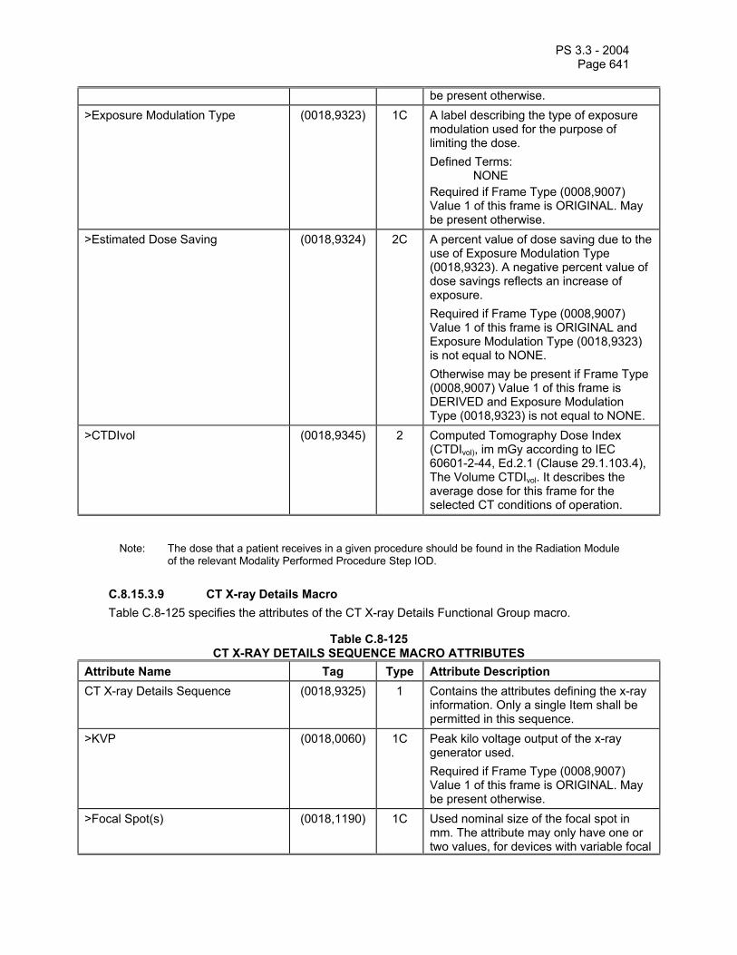
PS 3.3 - 2004 Page 641
be present otherwise. >Exposure Modulation Type (0018,9323) 1C A label describing the type of exposure
modulation used for the purpose of limiting the dose. Defined Terms: NONE Required if Frame Type (0008,9007) Value 1 of this frame is ORIGINAL. May be present otherwise.
>Estimated Dose Saving (0018,9324) 2C A percent value of dose saving due to the use of Exposure Modulation Type (0018,9323). A negative percent value of dose savings reflects an increase of exposure. Required if Frame Type (0008,9007) Value 1 of this frame is ORIGINAL and Exposure Modulation Type (0018,9323) is not equal to NONE. Otherwise may be present if Frame Type (0008,9007) Value 1 of this frame is DERIVED and Exposure Modulation Type (0018,9323) is not equal to NONE.
>CTDIvol (0018,9345) 2 Computed Tomography Dose Index (CTDIvol), im mGy according to IEC 60601-2-44, Ed.2.1 (Clause 29.1.103.4), The Volume CTDIvol. It describes the average dose for this frame for the selected CT conditions of operation.
Note: The dose that a patient receives in a given procedure should be found in the Radiation Module of the relevant Modality Performed Procedure Step IOD.
C.8.15.3.9 CT X-ray Details Macro Table C.8-125 specifies the attributes of the CT X-ray Details Functional Group macro.
Table C.8-125 CT X-RAY DETAILS SEQUENCE MACRO ATTRIBUTES
Attribute Name Tag Type Attribute Description CT X-ray Details Sequence (0018,9325) 1 Contains the attributes defining the x-ray
information. Only a single Item shall be permitted in this sequence.
>KVP (0018,0060) 1C Peak kilo voltage output of the x-ray generator used. Required if Frame Type (0008,9007) Value 1 of this frame is ORIGINAL. May be present otherwise.
>Focal Spot(s) (0018,1190) 1C Used nominal size of the focal spot in mm. The attribute may only have one or two values, for devices with variable focal

PS 3.3 - 2004 Page 642
spot, small dimension followed by large dimension Required if Frame Type (0008,9007) Value 1 of this frame is ORIGINAL. May be present otherwise.
>Filter Type (0018,1160) 1C Type of filter(s) inserted into the X-Ray beam. Defined Terms: WEDGE BUTTERFLY MULTIPLE FLAT SHAPED NONE Required if Frame Type (0008,9007) Value 1 of this frame is ORIGINAL. May be present otherwise.
>Filter Material (0018,7050) 1C The X-Ray absorbing material used in the filter. May be multi-valued. Defined Terms: MOLYBDENUM ALUMINUM COPPER RHODIUM NIOBIUM EUROPIUM LEAD Required if Frame Type (0008,9007) Value 1 of this frame is ORIGINAL. May be present otherwise.

PS 3.3 - 2004 Page 643
C.8.15.3.10 CT Pixel Value Transformation Macro Table C.8-126 specifies the attributes of the CT Pixel Value Transformation Functional Group macro.
Notes: 1. This Macro is equivalent to the Modality LUT transformation in non Multi-frame IODs. 2. This in effect specializes the C.7.6.16.2.9 Pixel Value Transformation Macro.
Table C.8-126 CT PIXEL VALUE TRANSFORMATION MACRO ATTRIBUTES
Attribute Name Tag Type Attribute Description Pixel Value Transformation Sequence
(0028,9145) 1 Contains the attributes involved in the transformation of stored pixel values. Only a single Item shall be permitted in this sequence.
>Rescale Intercept (0028,1052) 1 The value b in relationship between stored values (SV) and the output units. Output units = m*SV + b.
>Rescale Slope (0028,1053) 1 m in the equation specified by Rescale Intercept (0028,1052).
>Rescale Type (0028,1054) 1 Specifies the output units of Rescale Slope (0028,1053) and Rescale Intercept (0028,1052). See C.11.1.1.2 for further explanation. If Frame Type (0008,9007) Value 1 of this frame is ORIGINAL, the value shall be HU (Hounsfield Units).
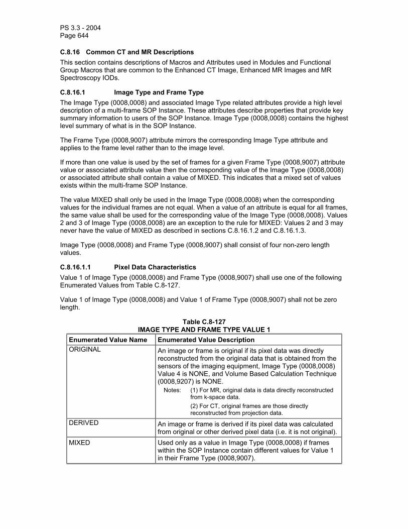
PS 3.3 - 2004 Page 644
C.8.16 Common CT and MR Descriptions This section contains descriptions of Macros and Attributes used in Modules and Functional Group Macros that are common to the Enhanced CT Image, Enhanced MR Images and MR Spectroscopy IODs.
C.8.16.1 Image Type and Frame Type The Image Type (0008,0008) and associated Image Type related attributes provide a high level description of a multi-frame SOP Instance. These attributes describe properties that provide key summary information to users of the SOP Instance. Image Type (0008,0008) contains the highest level summary of what is in the SOP Instance.
The Frame Type (0008,9007) attribute mirrors the corresponding Image Type attribute and applies to the frame level rather than to the image level.
If more than one value is used by the set of frames for a given Frame Type (0008,9007) attribute value or associated attribute value then the corresponding value of the Image Type (0008,0008) or associated attribute shall contain a value of MIXED. This indicates that a mixed set of values exists within the multi-frame SOP Instance.
The value MIXED shall only be used in the Image Type (0008,0008) when the corresponding values for the individual frames are not equal. When a value of an attribute is equal for all frames, the same value shall be used for the corresponding value of the Image Type (0008,0008). Values 2 and 3 of Image Type (0008,0008) are an exception to the rule for MIXED: Values 2 and 3 may never have the value of MIXED as described in sections C.8.16.1.2 and C.8.16.1.3.
Image Type (0008,0008) and Frame Type (0008,9007) shall consist of four non-zero length values.
C.8.16.1.1 Pixel Data Characteristics Value 1 of Image Type (0008,0008) and Frame Type (0008,9007) shall use one of the following Enumerated Values from Table C.8-127.
Value 1 of Image Type (0008,0008) and Value 1 of Frame Type (0008,9007) shall not be zero length.
Table C.8-127 IMAGE TYPE AND FRAME TYPE VALUE 1
Enumerated Value Name Enumerated Value Description ORIGINAL An image or frame is original if its pixel data was directly
reconstructed from the original data that is obtained from the sensors of the imaging equipment, Image Type (0008,0008) Value 4 is NONE, and Volume Based Calculation Technique (0008,9207) is NONE.
Notes: (1) For MR, original data is data directly reconstructed from k-space data.
(2) For CT, original frames are those directly reconstructed from projection data.
DERIVED An image or frame is derived if its pixel data was calculated from original or other derived pixel data (i.e. it is not original).
MIXED Used only as a value in Image Type (0008,0008) if frames within the SOP Instance contain different values for Value 1 in their Frame Type (0008,9007).

PS 3.3 - 2004 Page 645
C.8.16.1.2 Patient Examination Characteristics Value 2 for Image Type (0008,0008) and Frame Type (0008,9007) follows the standard definition and shall have the following Enumerated Value from Table C.8-128.
Value 2 of Image Type (0008,0008) and Value 2 of Frame Type (0008,9007) shall not be zero length.
Table C.8-128 IMAGE TYPE AND FRAME TYPE VALUE 2
Enumerated Value Name Enumerated Value Description PRIMARY See C.7.6.1.1.2
C.8.16.1.3 Image Flavor Value 3 is an overall representation of the image type. This value may be a summary of several other attributes or a duplication of one of the other attributes to indicate the most important aspect of this image. Value 3 Image Flavor is to be used with Value 4 Derived Pixel Contrast to indicate the nature of the image set.
Note: For example Value 3 = DIFFUSION together with Value 4 = NONE indicates that the image set was originally collected for DIFFUSION.
If Value 3 = DIFFUSION together with Value 4 = DIFFUSION this indicates that the object contains DIFFUSION weighted post processed images.
Value 3 of Image Type (0008,0008) shall not be zero length.
Value 3 of Frame Type (0008,9007) may have the same value as found in Value 3 of Image Type (0008,0008), or may have a different value or may be of zero length.
The attribute value may not be MIXED as this value needs to be a summary of the primary purpose of the images, whether the frames have the same value or not.
Table C.8-129 specifies the Defined Terms for Value 3 for Image Type (0008,0008) and Frame Type (0008,9007) that are common to CT and MR. Additional defined terms are defined in the modality-specific Module and Macro definitions.
Table C.8-129 IMAGE TYPE AND FRAME TYPE VALUE 3 COMMON
Defined Term Name Defined Term Description ANGIO Collected for the purpose of angiography FLUOROSCOPY Real-time collection of single slices (e.g. CT or MR
Fluoroscopy) LOCALIZER Collected for the purpose of planning other images. MOTION Collected for looking at body motion PERFUSION Collected for the purposes of perfusion calculations. PRE_CONTRAST Collected before contrast was administered POST_CONTRAST Collected during or after contrast was administered REST Cardiac rest image set STRESS Cardiac stress image set VOLUME Set of frames that define a volume
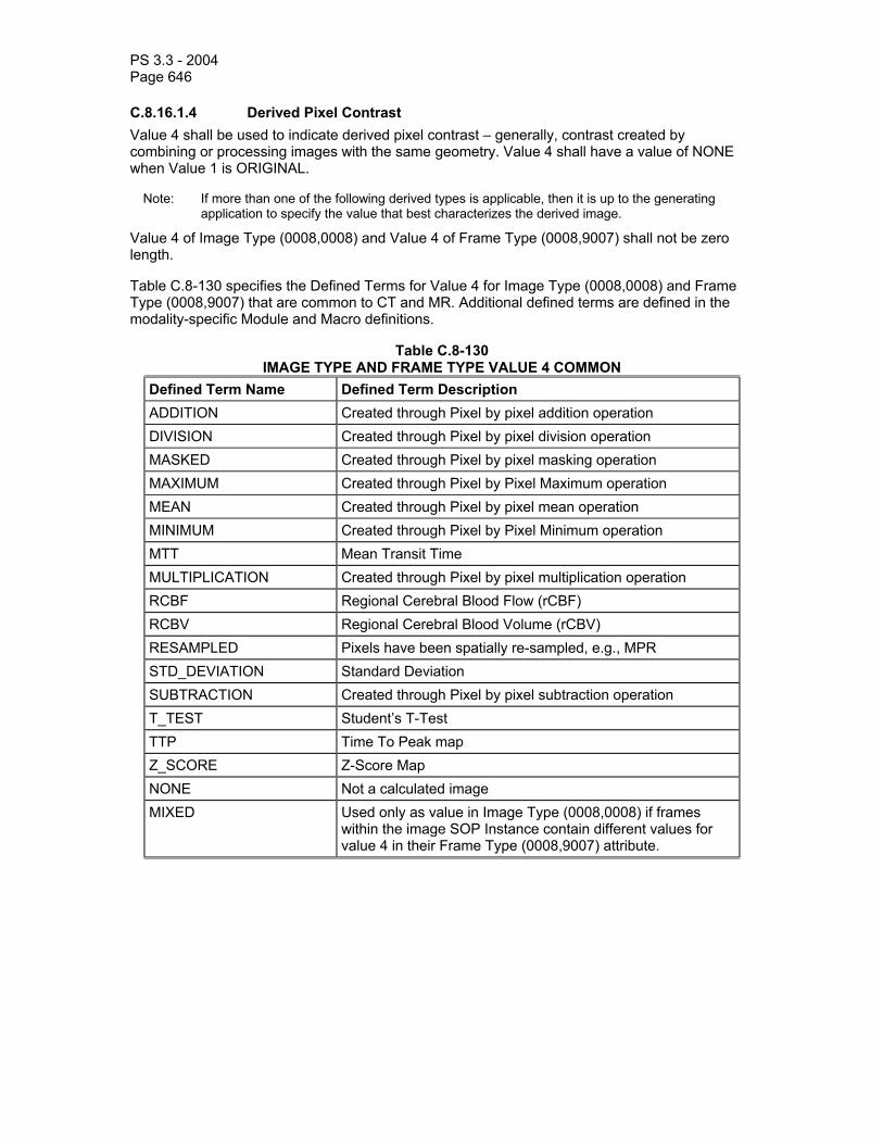
PS 3.3 - 2004 Page 646
C.8.16.1.4 Derived Pixel Contrast Value 4 shall be used to indicate derived pixel contrast – generally, contrast created by combining or processing images with the same geometry. Value 4 shall have a value of NONE when Value 1 is ORIGINAL.
Note: If more than one of the following derived types is applicable, then it is up to the generating application to specify the value that best characterizes the derived image.
Value 4 of Image Type (0008,0008) and Value 4 of Frame Type (0008,9007) shall not be zero length.
Table C.8-130 specifies the Defined Terms for Value 4 for Image Type (0008,0008) and Frame Type (0008,9007) that are common to CT and MR. Additional defined terms are defined in the modality-specific Module and Macro definitions.
Table C.8-130 IMAGE TYPE AND FRAME TYPE VALUE 4 COMMON
Defined Term Name Defined Term Description ADDITION Created through Pixel by pixel addition operation DIVISION Created through Pixel by pixel division operation MASKED Created through Pixel by pixel masking operation MAXIMUM Created through Pixel by Pixel Maximum operation MEAN Created through Pixel by pixel mean operation MINIMUM Created through Pixel by Pixel Minimum operation MTT Mean Transit Time MULTIPLICATION Created through Pixel by pixel multiplication operation RCBF Regional Cerebral Blood Flow (rCBF) RCBV Regional Cerebral Blood Volume (rCBV) RESAMPLED Pixels have been spatially re-sampled, e.g., MPR STD_DEVIATION Standard Deviation SUBTRACTION Created through Pixel by pixel subtraction operation T_TEST Student’s T-Test TTP Time To Peak map Z_SCORE Z-Score Map NONE Not a calculated image MIXED Used only as value in Image Type (0008,0008) if frames
within the image SOP Instance contain different values for value 4 in their Frame Type (0008,9007) attribute.
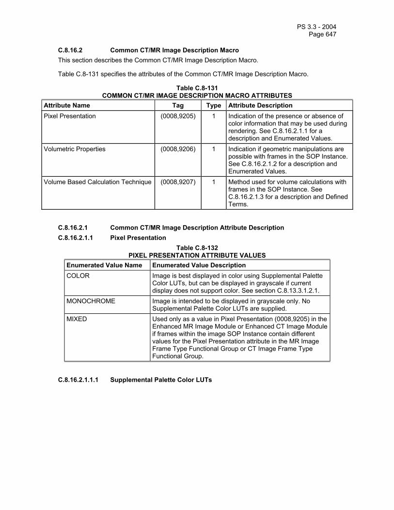
PS 3.3 - 2004 Page 647
C.8.16.2 Common CT/MR Image Description Macro This section describes the Common CT/MR Image Description Macro.
Table C.8-131 specifies the attributes of the Common CT/MR Image Description Macro.
Table C.8-131 COMMON CT/MR IMAGE DESCRIPTION MACRO ATTRIBUTES
Attribute Name Tag Type Attribute Description Pixel Presentation (0008,9205) 1 Indication of the presence or absence of
color information that may be used during rendering. See C.8.16.2.1.1 for a description and Enumerated Values.
Volumetric Properties (0008,9206) 1 Indication if geometric manipulations are possible with frames in the SOP Instance. See C.8.16.2.1.2 for a description and Enumerated Values.
Volume Based Calculation Technique (0008,9207) 1 Method used for volume calculations with frames in the SOP Instance. See C.8.16.2.1.3 for a description and Defined Terms.
C.8.16.2.1 Common CT/MR Image Description Attribute Description C.8.16.2.1.1 Pixel Presentation
Table C.8-132 PIXEL PRESENTATION ATTRIBUTE VALUES
Enumerated Value Name Enumerated Value Description COLOR Image is best displayed in color using Supplemental Palette
Color LUTs, but can be displayed in grayscale if current display does not support color. See section C.8.13.3.1.2.1.
MONOCHROME Image is intended to be displayed in grayscale only. No Supplemental Palette Color LUTs are supplied.
MIXED Used only as a value in Pixel Presentation (0008,9205) in the Enhanced MR Image Module or Enhanced CT Image Module if frames within the image SOP Instance contain different values for the Pixel Presentation attribute in the MR Image Frame Type Functional Group or CT Image Frame Type Functional Group.
C.8.16.2.1.1.1 Supplemental Palette Color LUTs

PS 3.3 - 2004 Page 648
Figure C.8-20 presents two separate image visualization pipelines that can be used for interpreting the stored pixel values.
If Pixel Presentation (0008,9205) equals COLOR, the stored values are split into two ranges. The stored values up to one less than the second value of the Red, Green and Blue Palette Color Lookup Table Descriptor (0028,1101-1103)are passed through the gray scale visualization pipeline. The values equal to or greater than the second value of the Red, Green and Blue Palette Color Lookup Table Descriptor (0028,1101-1103) are mapped by the Palette Color LUTs.
Notes: 1. Some images may be purely color, and there will be no grayscale range of stored pixel values “below” those that are passed through the color lookup tables.
2. Images containing Supplemental Palette Color LUTs cannot be irreversibly (lossy) compressed, since that would potentially change the index values and result in different colors being rendered.
The complete range of stored pixel values can also be displayed via the grayscale visualization pipeline only, but the information content may be less useful because the color information is not available.
....
Range ofStored
Values to bemapped tograyscale
Range ofStored
Values to bemapped to
color
R G B
First StoredPixel ValueMapped (2nd
value of LUTDescriptor)
ModalityLUT
ColorDisplay
Mapped to gray levelRGB values by displaydeviceVOI
LUTP-
LUT
+
Figure C.8-20 MONOCHROME2 Photometric Interpretation with Supplemental Palette Color mapping
C.8.16.2.1.2 Volumetric Properties The value of the Volumetric Properties attribute (0008,9206) allows applications doing geometric manipulations (e.g., MAX_IP or MPR or planning) to determine if the image is an appropriate candidate for an operation without having to know all the details of the generating application.
Table C.8-133 specifies the Enumerated Values for the Volumetric Properties (0008,9206) attribute.
Table C.8-133 VOLUMETRIC PROPERTIES ATTRIBUTE VALUES
Enumerated Value Name Enumerated Value Description VOLUME Image contains pixels that represent the volume specified for
the image (Examples: Volume Based Calculation Technique (0008,9207) is NONE or MPR).

PS 3.3 - 2004 Page 649
SAMPLED The specified frame or each frame within the image will not contain a representation of the average information in the slice direction because the frame was calculated by the non-linear re-sampling of a volume where each pixels of the resulting frame does not contain an average representation of the voxel represented by the frame's pixel. For example a projection (MAX_IP) frame uses the maximum value along a ray for each pixel rather than the average value of the represented voxel.
DISTORTED Image contains significantly distorted information from what is specified by the image volume attributes. For example this image should not be used in planning or for 3D volume. An example of this image type is a curved reformatted image (CURVED_MPR).
MIXED Used only as a value in the Volumetric Properties (0008,9206) attribute in the Enhanced MR Image Type Module or Enhanced CT Image Type Module if frames within the image SOP Instance contain different values for the Volumetric Properties (0008,9206) attributes in the MR Image Frame Type Functional Group or CT Frame Type Functional Group.

PS 3.3 - 2004 Page 650
C.8.16.2.1.3 Volume Based Calculation Technique Attribute The value of the Volume Based Calculation Technique attribute (0008,9207) shall be used to indicate the method used for calculating pixels based on geometry.
Shall have a value of NONE when Value 1 of Image Type (0008,0008) or Value 1 of Frame Type (0008,9007) is ORIGINAL.
Table C.8-134 specifies the Defined Terms for the Volume Based Calculation Technique (0008,9207) attribute.
Table C.8-134 VOLUME BASED CALCULATION TECHNIQUE ATTRIBUTE VALUES
Defined Term Name Defined Term Description MAX_IP Maximum Intensity Projection MIN_IP Minimum Intensity Projection VOLUME_RENDER Volume Rendering Projection
Volume Rendering Image represents 3D voluminar information constructed from measured voxel intensities covering a 3D volume.
SURFACE_RENDER Surface Rendering Projection Surface Rendering Image represents 3D surface information constructed from measured voxel intensities covering a 3D volume.
MPR Multi-Planar Reformat CURVED_MPR Curved Multi-Planar Reformat NONE Pixels not derived geometrically MIXED Used only as a value in Volume Based Calculation
Technique (0008,9207) attribute in the Enhanced MR Image Module or MR Spectroscopy Module if frames within the image SOP Instance contain different terms for the Volume Based Calculation Technique attribute in MR Frame Type Functional Group or MR Spectroscopy Frame Type Functional Group.
C.8.17 Ophthalmic Photography Modules C.8.17.1 Ophthalmic Photography Series Module Table C.8.17.1-1 specifies the attributes that describe an Ophthalmic Photography Series.
Table C.8.17.1-1 OPHTHALMIC PHOTOGRAPHY SERIES MODULE ATTRIBUTES
Attribute Name Tag Type Attribute Description Modality (0008,0060) 1 Source equipment that produced the Ophthalmic
Photography Series. Enumerated Value: OP C.8.17.2 Ophthalmic Photography Image Module Table C.8.17.2-1 specifies the Attributes that describe an Ophthalmic Photography Image produced by Ophthalmic Photography equipment (OP) imaging Modalities.

PS 3.3 - 2004 Page 651
Table C.8.17.2-1 OPHTHALMIC PHOTOGRAPHY IMAGE MODULE ATTRIBUTES
Attribute Name Tag Type Attribute Description Image Type (0008,0008) 1 Image identification characteristics.
See C.8.17.2.1.4 for specialization. Instance Number (0020,0013) 1 A number that identifies this image.
Samples per Pixel (0028,0002) 1 Number of samples (planes) in this image. Enumerated
values: 1 or 3. See C.8.17.2.1.2 for further explanation.
Samples per Pixel Used
(0028,0003) 1C The number of samples (planes) containing information. Enumerated value: 2. Required if different from Samples per Pixel (0028,0002). See section C.8.17.2.1.2
Photometric Interpretation
(0028,0004) 1 Specifies the intended interpretation of the pixel data. See section C.8.17.2.1.3
Pixel Representation
(0028,0103) 1 Data representation of the pixel samples. Enumerated value: 0
Planar Configuration
(0028,0006) 1C Indicates whether the pixel data are sent color-by-plane or color-by-pixel. Required if Samples per Pixel (0028,0002) has a value greater than 1. Enumerated value shall be 0 (color-by-pixel).
Pixel Spacing (0028,0030) 1C Nominal physical distance at the focal plane (in the retina) between the center of each pixel, specified by a numeric pair - adjacent row spacing (delimiter) adjacent column spacing in mm.
Note: These values are specified as nominal because the physical distance may vary across the field of the images and the lens correction is likely to be imperfect.
Required when Acquisition Device Type Code Sequence (0022,0015) contains an item with the value (SRT, R-1021A,”Fundus Camera”). May be present otherwise.
Content Time (0008,0033) 1 The time the image pixel data creation started. Content Date (0008,0023) 1 The date the image pixel data creation started. Acquisition Datetime
(0008,002A) 1C The date and time that the acquisition of data started. Note: The synchronization of this time with an external clock
is specified in the synchronization Module in Acquisition Time Synchronized (0018,1800).
Required if Image Type (0008,0008) Value 1 is ORIGINAL. May be present otherwise.
Source Image Sequence
(0008,2112) 2C A Sequence that identifies the set of Image SOP Class/Instance pairs of the Images that were used to derive this Image. Required if Image Type Value 1 is DERIVED. Zero or more items may be present in the sequence. See C.7.6.1.1.4 for further explanation.
>Include Image SOP Instance Reference Macro, Table 10-3

PS 3.3 - 2004 Page 652
>Purpose of Reference Code Sequence
(0040,A170) 1C Describes the purpose for which the reference is made, that is what role the source image or frame(s) played in the derivation of this image.
>>Include ‘Code Sequence Macro’ Table 8.8-1
Defined Context ID is 7202.
Lossy Image Compression
(0028,2110) 1 Specifies whether an Image has undergone lossy compression. Enumerated Values:
00 = Image has NOT been subjected to lossy compression.
01 = Image has been subjected to lossy compression.
See C.7.6.1.1.5 Lossy Image Compression Ratio
(0028,2112) 1C Describes the approximate lossy compression ratio(s) that have been applied to this image. See C.7.6.1.1.5 for further explanation. May be multivalued if successive lossy compression steps have been applied.
Notes: 1. For example, a compression ratio of 30:1 would be described in this Attribute with a single value of 30.
2. For historical reasons, the lossy compression ratio should also be described in Derivation Description (0008,2111)
Required if Lossy Image Compression (0028,2110) has a value of “01”.
Lossy Image Compression Method
(0028,2114) 1C A label for the lossy compression method(s) that have been applied to this image. See C.7.6.1.1.5 for further explanation. May be multivalued if successive lossy compression steps have been applied; the value order shall correspond to the values of Lossy Image Compression Ratio (0028,2112). Required if Lossy Image Compression (0028,2110) has a value of “01”.
Note: For historical reasons, the lossy compression method should also be described in Derivation Description (0008,2111).
Presentation LUT Shape
(2050,0020) 1C Specifies an identity transformation for the Presentation LUT, such that the output of all grayscale transformations defined in the IOD containing this Module are defined to be P-Values. Enumerated Values: IDENTITY - output is in P-Values. Required if Photometric Interpretation (0028,0004) is MONOCHROME2
Calibration Image (0050,0004) 3 Indicates whether a reference object (phantom) of known size is present in the image and was used for calibration. Enumerated Values:
YES NO

PS 3.3 - 2004 Page 653
Burned In Annotation
(0028,0301) 1 Indicates whether or not image contains sufficient burned in annotation to identify the patient and date the image was acquired. Enumerated Value: YES NO
C.8.17.2.1 Ophthalmic Photography Image Module Attribute Descriptions C.8.17.2.1.1 Referenced Image Sequence The Referenced Image Sequence (0008,1140) in the General Image Module (Section C.7.6.1) shall not convey stereoscopic information, which instead shall be encoded using the Stereometric Relationship IOD.
C.8.17.2.1.2 Samples per Pixel and Samples per Pixel Used Samples per Pixel (0028,0002) shall be 1 or 3.
Cameras producing 2-color images are required to use a value of 3 for Samples per Pixel (0028,0002) and a value of 2 for Samples per Pixel Used (0028,0003). For 2-color images with a RGB Photometric Interpretation, the R and G channel shall be used and the B channel shall have all values set to zero.
Note: In the case of Photometric Interpretations typically used for compression such as YBR_FULL_422, the encoding will be as if the RGB values were transformed to YCbCr.
C.8.17.2.1.3 Photometric Interpretation Specifies the intended interpretation of the pixel data. Enumerated Values shall be:
MONOCHROME2 RGB YBR_FULL_422 YBR_PARTIAL_420 YBR_ICT YBR_RCT
C.8.17.2.1.4 Image Type The Image Type attribute (0008,0008) (General Image Module, C.7.6.1) identifies important image characteristics in a multiple valued data element. For the Ophthalmic Photography Image IOD, Image Type is specified as a Type 1 attribute and further specialized as follows:
a. Value 1 shall identify the Pixel Data Characteristics in accordance with Section C.7.6.1.1.2; Enumerated Values are: ORIGINAL and DERIVED;
b. Value 2 shall identify the Patient Examination Characteristics in accordance with Section C.7.6.1.1.2; Enumerated Value is: PRIMARY
c. Value 3 shall only be present if Value 1 is DERIVED; Defined Terms: MONTAGE. d. Value 4 (optionally present) shall identify the type of test performed for image acquisition.
Defined terms: COLOR - a picture take at “white” light; no filters applied REDFREE - a picture take at “green” illumination light; or just the green channel of a
color sensor

PS 3.3 - 2004 Page 654
RED - a picture take at “red” illumination light; or just the red channel of a color sensor
BLUE - a picture take at “blue” illumination light; or just the blue channel of a color sensor
FA- fluorescein injected; a picture taken at fluorescein exciting illumination light; a filter passing just the emitted wavelength to sensor applied
ICG - Indocyanine green injected; a picture taken at Indocyanine green exciting illumination light; a filter passing just the emitted wavelength to sensor applied
Note: A Montage Image is constructed out of several individual images, which also can be exchanged separately. The images used to create the montage image will be included in the source image sequence if those images are also exchanged. A Montage Image is identified as Image Type DERIVED\PRIMARY\MONTAGE
C.8.17.3 Ophthalmic Photographic Parameters Module This Module describes equipment used to create original images.

PS 3.3 - 2004 Page 655
Table C.8.17.3-1 OPHTHALMIC PHOTOGRAPHIC PARAMETERS MODULE ATTRIBUTES
Attribute Name Tag Type Attribute Description Acquisition Device Type Code Sequence
(0022,0015) 1 Describes the type of acquisition device. A single item shall be present in the sequence.
>Include ‘Code Sequence Macro’ Table 8.8.1 Baseline Context ID is 4202 Illumination Type Code Sequence (0022,0016) 2 Coded value for illumination. Zero or one
item shall be present in the sequence. >Include ‘Code Sequence Macro’ Table 8.8.1 Baseline Context ID is 4203 Light Path Filter Type Stack Code Sequence
(0022,0017) 2 Filters used in the light source path. Zero or more items may be present in the sequence.
>Include ‘Code Sequence Macro’ Table 8.8.1 Baseline Context ID is 4204 Light Path Filter Pass-Through Wavelength
(0022,0001) 3 Nominal pass-through wavelength of light path filter in nm
Light Path Filter Pass Band (0022,0002) 3 Pass band of light path filter in nm. This Attribute has two Values. The first is the shorter and the second the longer wavelength relative to the peak. The values are for the – 3dB nominal (1/2 of peak) pass through intensity. One of the two Values may be zero length, in which case it is a cutoff filter.
Image Path Filter Type Stack Code Sequence
(0022,0018) 2 Describes stack of filters used in image path. Zero or more items may be present in the sequence.
>Include ‘Code Sequence Macro’ Table 8.8.1 Baseline Context ID is 4204 Image Path Filter Pass-Through Wavelength
(0022,0003) 3 Nominal pass-through wavelength of image path filter in nm
Image Path Filter Pass Band (0022,0004) 3 Pass band of image path filter in nm. This Attribute has two Values. The first is the shorter and the second the longer wavelength relative to the peak. The values are for the – 3dB nominal (1/2 of peak) pass through intensity. One of the two Values may be zero length, in which case it is a cutoff filter
Lenses Code Sequence (0022,0019) 2 Lenses that were used during the image acquisition. Zero or more items may be present in the sequence.
>Include ‘Code Sequence Macro’ Table 8.8.1 Baseline Context ID is 4205 Detector Type (0018,7004) 2 Type of detector used for creating this
image. Defined terms: CCD = Charge Coupled Devices CMOS = Complementary Metal Oxide Semiconductor

PS 3.3 - 2004 Page 656
Channel Description Code Sequence (0022,001A) 1C Describes the light color used for each channel to generate the image. Required if this differs from the natural interpretation.
Note: Interpretation and representation of RGB images rely on the assumption that the red channel really contains the red wavelength range of illumination light, the blue channel the blue wavelength range, etc. Some modalities use the RGB Photometric Interpretation as a container representing 3 channels of any illumination wavelength.
Shall have the same number of items as the Value of Samples per Pixel Used (0028,0003) if present, or otherwise the value of Samples per Pixel (0028,0002). The channels shall be described in the order in which the channels are encoded.
>Include ‘Code Sequence Macro’ Table 8.8.1 Baseline Context ID is 4206

PS 3.3 - 2004 Page 657
C.8.17.4 Ophthalmic Photography Acquisition Parameters Module This Module describes patient clinical conditions related to the image acquisition.
Table C.8.17.4-1 OPHTHALMIC PHOTOGRAPHY ACQUISITION PARAMETERS MODULE ATTRIBUTES
Attribute Name Tag Type Attribute Description Patient Eye Movement Commanded (0022,0005) 2 Enumerated Values:
YES NO
Patient Eye Movement Command Code Sequence
(0022,0006) 1C Coded value for patient movement or orientation, which is the intent, and not necessarily the result, based on what the patient is capable of. Required if the value of Patient Eye Movement Commanded (0022,0005) is YES. A single item shall be present in this sequence.
>Include ‘Code Sequence Macro’ Table 8.8.1 Baseline Context ID is 4201 Refractive State Sequence (0022,001B) 2 The refractive state of the imaged eye at
the time of acquisition. Zero or one Item shall be present. Absence of an item means the refractive state was not measured.
> Spherical Lens Power (0022,0007) 1 Sphere value in diopters > Cylinder Lens Power (0022,0008) 1 Cylinder value in diopters > Cylinder Axis (0022,0009) 1 Axis value in degrees Emmetropic Magnification (0022,000A) 2 Emmetropic Magnification value
(dimensionless). Zero length means the emmetropic magnification was not measured.
Intra Ocular Pressure (0022,000B) 2 Value of pressure. Value in mmHg. Zero length means the pressure was not measured.
Horizontal Field of View (0022,000C) 2 The horizontal field of view in degrees Pupil Dilated (0022,000D) 2 Enumerated Values:
YES NO
Mydriatic Agent Code Sequence (0022,001C) 2C The agent administered to dilate the pupil. Required if the value of Pupil Dilated (0022,000D) is YES. Zero or more items may be present.
>Include ‘Code Sequence Macro’ Table 8.8.1 Baseline Context ID is 4208 Degree of Dilation (0022,000E) 2C The degree of the dilation in mm
Required if the value of Pupil Dilated (0022,000D) is YES.

PS 3.3 - 2004 Page 658
C.8.17.5 Ocular Region Imaged Module Table C.8.17.5-1 contains IOD Attributes that describe the anatomy contained in an OP IOD.
Table C.8.17.5-1 OCULAR REGION IMAGED MODULE ATTRIBUTES
Attribute Name Tag Type Attribute Description Image Laterality (0020,0062) 1 Laterality of object imaged (as described
in Anatomic Region Sequence (0008,2218)) examined. Enumerated Values: R = right eye L = left eye B = both left and right eye Shall be consistent with any laterality information contained in Primary Anatomic Structure Modifier Sequence (0008,2230), if present.
Note: Laterality (0020,0060) is a Series level Attribute and must be the same for all Images in the Series. Since most Ophthalmic Photographic Image studies contain images of both eyes, the series level attribute will rarely be present.
Relative Image Position Code Sequence
(0022,001D) 3 The position of this image on the retina (as defined by a specified nomenclature; the nomenclature is implicit in the code used).
>Include ‘Code Sequence Macro’ Table 8.8.1 Baseline Context ID 4207 Include 'General Anatomy Mandatory Macro' Table 10-5 Defined Context ID 4209 for Anatomic
Region Sequence
C.8.18 Stereometric Modules C.8.18.1 Stereometric Series Module Table C.8.18.1-1 specifies the Attributes that describe a Stereometric Series produced by Ophthalmic Photography equipment (OP) imaging Modalities.
Table C.8.18.1-1 STEREOMETRIC SERIES MODULE ATTRIBUTES
Attribute Name Tag Type Attribute Description Modality (0008,0060) 1 Source equipment that produced the Stereometric Series.
Enumerated Value: SMR C.8.18.2 Stereometric Relationship Module The stereometric relationship module is used to identify pairs of images that may be viewed in stereo. It is possible that the same image or frame may be a member of multiple pairs. The images forming a pair shall be in different SOP Instances. The images forming a pair can be in

PS 3.3 - 2004 Page 659
different Series. All Instances referenced in this Module shall be in the same Study as the Instance in which the Module occurs.
Table C.8.18.2 -1
STEREOMETRIC RELATIONSHIP MODULE ATTRIBUTES Attribute Name Tag Type Attribute Description Stereo Pairs Sequence (0022,0020) 1 Sequence of items identifying pairs of
images. There shall be one or more items in this sequence.
>Stereo Baseline Angle (0022,0010) 3 Stereo separation angle in degrees >Stereo Baseline Displacement (0022,0011) 3 Horizontal displacement of instrument
between left and right image in mm >Stereo Horizontal Pixel Offset (0022,0012) 3 Horizontal displacement of right image
relative to left image in pixels for optimal display. Offset of right image to right means positive value.
>Stereo Vertical Pixel Offset (0022,0013) 3 Vertical displacement of right image relative to left image in pixels for optimal display. Offset of right image downwards means positive value.
>Stereo Rotation (0022,0014) 3 Rotation of right image relative to left image in degrees for optimal display. The rotation of the right image against the left image counterclockwise is positive, rotation around the center is assumed.
>Left Image Sequence (0022,0021) 1 Left Image of the Pair. Only one Item shall be present in this Sequence.
>>Include Image SOP Instance Reference Macro, Table 10-3 The Referenced SOP Instance UID (0008,1155) shall not be the same as the Referenced SOP Instance UID (0008,1155) of the Right Image Sequence (0022,0022).
>Right Image Sequence (0022,0022) 1 Right Image of the Pair. Only one Item shall be present in this Sequence.
>>Include Image SOP Instance Reference Macro, Table 10-3 The Referenced SOP Instance UID (0008,1155) shall not be the same as the Referenced SOP Instance UID (0008,1155) of the Left Image Sequence (0022,0021).
C.8.18.2.1 Stereometric Relationship Module Attribute Descriptions C.8.18.2.1.1 Left and Right Image Sequences The images referenced by the Left Image Sequence (0022,0021) and Right Image Sequence (0022,0022) in a single Stereo Pairs Sequence Item shall have the same values for Rows (0028,0010) and the same values for Columns (0028,0011).
The reference may be to images with a single frame, all the frames of images with multiple frames, or one or more selected frames within an image with multiple frames. If multiple frames are selected, the same number of frames shall be referenced from both sequences.

PS 3.3 - 2004 Page 660
C.9 OVERLAYS
C.9.1 Overlay identification module Table C.9-1 contains Attributes that identify an independent Overlay; i.e. an Overlay that is handled as an independent Information Entity.
Table C.9-1 OVERLAY IDENTIFICATION MODULE ATTRIBUTES
Attribute Name Tag Type Attribute Description Overlay Number (0020,0022) 2 A number that identifies this Overlay. Overlay Date (0008,0024) 3 The date the Overlay was created. Overlay Time (0008,0034) 3 The time the Overlay was created. Referenced Image Sequence (0008,1140) 3 A Sequence that provides reference to a
set of Image SOP Class/Instance pairs. Uniquely identifies the images significantly related to this overlay. One or more Items may be included in this Sequence.
>Referenced SOP Class UID (0008,1150) 1C Uniquely identifies the referenced SOP Class. Required if Referenced Image Sequence (0008,1140) is sent.
>Referenced SOP Instance UID (0008,1155) 1C Uniquely identifies the referenced SOP Instance. Required if Reference Image Sequence (0008,1140) is sent.
C.9.2 Overlay plane module Table C.9-2 contains Attributes that describe characteristics of an Overlay Plane.
An Overlay Plane describes graphics or bit-mapped text that is associated with an Image or has its own existence within a Series. It may also describe a Region of Interest in an Image.
Each Overlay Plane is one bit deep. Sixteen separate Overlay Planes may be associated with an Image or exist as Standalone Overlays in a Series.
Overlay pixel data are stored either in Overlay Data (60xx,3000) or embedded in the image pixel data in Image Pixel Data (7FE0,0010). See PS 3.5 for a description of overlay pixel data imbedded with image pixel data. See the Section Repeating Groups in PS 3.5 for a description of permitted values of 60xx. Overlay Planes embedded in Image Pixel data (7FE0,0010) are only permitted when Samples per Pixel (0028,0002) has a value of 1.
Attributes describing display of grayscale and color overlays were defined in a previous version of the DICOM Standard. These have now been retired. How an Overlay Plane is rendered is undefined; specifically there is no mechanism to specify with what color or intensity an Overlay Plane is to be displayed, except when rendered under the control of a Grayscale Softcopy Presentation State SOP Instance.
Table C.9-2 OVERLAY PLANE MODULE ATTRIBUTES
Attribute Name Tag Type Attribute Description Overlay Rows (60xx,0010) 1 Number of Rows in Overlay. Overlay Columns (60xx,0011) 1 Number of Columns in Overlay.

PS 3.3 - 2004 Page 661
Overlay Type (60xx,0040) 1 Indicates whether this overlay represents a region of interest or other graphics. Enumerated Values: G = Graphics R = ROI.
Overlay Origin (60xx,0050) 1 Location of first overlay point with respect to pixels in the image, given as row\column. The upper left pixel of the image has the coordinate 1\1. Column values greater than 1 indicate the overlay plane origin is to the right of the image origin. Row values greater than 1 indicate the overlay plane origin is below the image origin. Values less than 1 indicate the overlay plane origin is above or to the left of the image origin.
Note: Values of 0\0 indicate that the overlay pixels start 1 row above and one column to the left of the image pixels.
Overlay Bits Allocated (60xx,0100) 1 Number of Bits Allocated in the Overlay. If the overlay data are embedded in the Image Pixel Data (7FE0,0010), the value of this Attribute shall be the same as Bits Allocated (0028,0100). If the overlay data are stored in the Overlay Data (60xx,3000) Attribute, the value of this Attribute shall be 1.
Overlay Bit Position (60xx,0102) 1 Bit in which Overlay is stored. See PS 3.5 for further explanation. If the overlay data are stored in the Overlay Data (60xx,3000) Attribute, the value of this Attribute shall be 0.
Overlay Data (60xx,3000) 1C Overlay pixel data. The order of pixels sent for each overlay is left to right, top to bottom, i.e., the upper left pixel is sent first followed by the remainder of the first row , followed by the first pixel of the 2nd row, then the remainder of the 2nd row and so on. Overlay data shall be contained in this Attribute or imbedded with the image pixel data in Group 7FE0. Required if overlay data are in this Group. See C.9.2.1.1 for further explanation.
Overlay Description (60xx,0022) 3 User-defined comments about the overlay.

PS 3.3 - 2004 Page 662
Overlay Subtype (60xx,0045) 3 Defined term which identifies the intended purpose of the Overlay Type. See C.9.2.1.3 for further explanation.
Overlay Label (60xx,1500) 3 A user defined text string which may be used to label or name this overlay.
ROI Area (60xx,1301) 3 Number of pixels in ROI area. See C.9.2.1.2 for further explanation.
ROI Mean (60xx,1302) 3 ROI Mean. See C.9.2.1.2 for further explanation.
ROI Standard Deviation (60xx,1303) 3 ROI standard deviation. See C.9.2.1.2 for further explanation.
C.9.2.1 Overlay Attribute Descriptions C.9.2.1.1 Overlay type There are two specific types of overlays. The type is specified in this Attribute.
A Region of Interest (ROI) is a specific use of an Overlay. The overlay bits corresponding to all the pixels included in the ROI shall be set to 1. All other bits are set to 0. This is used to specify an area of the image of particular interest.
A Graphics overlay may express reference marks, graphic annotation, or bit mapped text, etc. A Graphics overlay may be used to mark the boundary of a ROI. If this is the case and the ROI statistical parameters are used, they will only refer to the pixels under the boundaries, not those in the included regions.
The overlay bits corresponding to all the pixels included in the Graphics shall be set to 1. All other bits are set to 0.
C.9.2.1.2 ROI area, ROI mean, and ROI standard deviation These Attributes contain the statistical parameters of the ROI. The values of these parameters are for the overlay pixel values set to 1.
C.9.2.1.3 Overlay Subtype Two Defined Terms are specified:
USER - User created graphic annotation (e.g. operator) AUTOMATED - Machine or algorithm generated graphic annotation, such as output of a
Computer Assisted Diagnosis algorithm. Note: Additional or alternative Defined Terms may be specified in modality specific Modules, such as
in the Ultrasound Image Module, C.8.5.6.1.11.

PS 3.3 - 2004 Page 663
C.9.3 Multi-frame Overlay Module Table C.9-3 specifies the Attributes of a Multi-frame overlay.
Table C.9-3 MULTI-FRAME OVERLAY MODULE ATTRIBUTES
Attribute Name Tag Type Attribute Description Number of Frames in Overlay (60xx,0015) 1 Number of Frames in Overlay. Required if
Overlay data contains multiple frames. Image Frame Origin (60xx,0051) 3 Frame number of Multi-frame Image to
which this overlay applies; frames are numbered from 1.
C.9.3.1 Multi-Frame Overlay Attribute Descriptions C.9.3.1.1 Number of frames in overlay A Multi-frame Overlay is defined as an Overlay whose overlay data consists of a sequential set of individual Overlay frames. A Multi-frame Overlay is transmitted as a single contiguous stream of overlay data. Frame delimiters are not contained within the data stream.
Each individual frame shall be defined (and thus can be identified) by the Attributes in the Overlay Plane Module (see C.9.2).
The total number of frames contained within a Multi-frame Overlay is conveyed in the Number of Frames in Overlay (60xx,0015).
The frames within a Multi-frame Overlay shall be conveyed as a logical sequence. If Multi-frame Overlays are related to a Multi-frame Image, the order of the Overlay Frames are one to one with the order of the Image frames. Otherwise, no attribute is used to indicate the sequencing of the Overlay Frames. If Image Frame Origin (60xx,0051) is present, the Overlay frames are applied one to one to the Image frames, beginning at the indicated frame number. Otherwise, no attribute is used to indicated the sequencing of the Overlay Frames.
The Number of Frames in Overlay (60xx,0015) plus the Image Frame Origin (60xx,0051) minus 1 shall be less than or equal to the total number of frames in the Multi-frame Image.
If the Overlay data are embedded in the pixel data, then the Image Frame Origin (60xx,0051) must be 1 and the Number of Frames in Overlay (60xx,0015) must equal the number of frames in the Multi-frame Image.
C.9.4 Bi-Plane Overlay Module (Retired) C.9.5 Basic Print Image Overlay Box Module
Table C.9-5: Basic Print Image Overlay Box Module Attribute Name Tag Attribute Description Overlay Pixel Data Sequence (2040,0020) A sequence which provides overlay
pixel data. A single item shall be present.
>Overlay Rows (6000,0010) See C.9.2. >Overlay Columns (6000,0011) See C.9.2. >Overlay Origin (6000,0050) See C.9.2 >Overlay Bits Allocated (6000,0100) Number of bits allocated in the
Overlay.

PS 3.3 - 2004 Page 664
Enumerated Value: 1 >Overlay Bit Position (6000,0102) Bit in which Overlay is stored.
Enumerated Value: 0 >Overlay Data (6000,3000) Overlay data shall be contained in
this Attribute. Overlay Magnification Type (2040,0060) Specifies magnification type if the
overlay is magnified before being superimposed on the image. Defined Terms: REPLICATE BILINEAR CUBIC
Overlay Smoothing Type (2040,0070) Further specifies the type of interpolation function; only valid for Overlay Magnification Type (2010,0060) = CUBIC
Overlay or Image Magnification (2040,0072) Specifies magnification of the overlay or image before they are superimposed. Enumerated values: IMAGE = Image is to be magnified OVERLAY = Overlay is to be magnified. See C.9.5.1
Magnify to Number of Columns (2040,0074) Specifies the number of columns of the overlay or image after magnification. See C.9.5.1
Overlay Foreground Density (2040,0080) Defines the density for pixels which correspond with overlay bit = 1. The density of the other pixels remain unchanged. Defined Terms: BLACK WHITE
Overlay Background Density (2040,0082) Defines the density for pixels which correspond with overlay bit = 0 that are not superimposed on the image and Combined Print Image pixels that are not part of the overlay or image Defined Terms: BLACK WHITE
Note: Since the SOP Class that uses this Module supports only one overlay plane, Group 60xx Attributes have been specified to be Group 6000 rather than 60xx.

PS 3.3 - 2004 Page 665
C.9.5.1 Overlay or Image Magnification These Attributes specify any magnification of the overlay or image that has to be performed before they are superimposed. Overlay or Image Magnification (2040,0072) specifies whether the overlay or image is to be magnified. Magnify to Number of Columns (2040,0074) specifies the number of columns of the overlay or image after magnification. If Overlay or Image Magnification has the value OVERLAY, this value shall be greater than Overlay Columns (6000,0011). If Overlay or Image Magnification has the value IMAGE, this value shall be greater than Columns (0028,0011).
Since the SOP Class that uses this Module does not provide a mechanism to specify an overlay pixel aspect ratio different than the image that refers to it, the same magnification factor shall be applied to the rows and columns of the overlay or image before they are superimposed. See Basic Print Image Overlay Box SOP Class in PS 3.4.

PS 3.3 - 2004 Page 666
C.10 CURVE, GRAPHIC AND WAVEFORM
C.10.1 Curve identification module The table in this Section contains Attributes that identify an independent Curve; i.e. a Curve which is handled as a separate information entity.
Table C.10-1 CURVE IDENTIFICATION MODULE ATTRIBUTES
Attribute Name Tag Type Attribute Description Curve Number (0020,0024) 2 A number that identifies this Curve. Curve Date (0008,0025) 3 The date the Curve was created. Curve Time (0008,0035) 3 The time the Curve was created. Referenced Image Sequence (0008,1140) 3 A Sequence which provides reference to a
set of Image SOP Class/Instance pairs. Uniquely identifies the images significantly related to this Curve. One or more Items may be included in this Sequence.
>Referenced SOP Class UID (0008,1150) 1C Uniquely identifies the referenced SOP Class. Required if Referenced Image Sequence (0008,1140) is sent.
>Referenced SOP Instance UID (0008,1155) 1C Uniquely identifies the referenced SOP Instance. Required if Reference Image Sequence (0008,1140) is sent.
Referenced Overlay Sequence (0008,1130) 3 A Sequence which provides reference to a set of SOP Class/Instance pairs which are related independent Overlays. Uniquely identifies Overlays significantly related to this Curve. Zero or more Items may be included in this Sequence.
>Referenced SOP Class UID (0008,1150) 1C Uniquely identifies the referenced SOP Class. Required if Referenced Overlay Sequence (0008,1130) is sent.
>Referenced SOP Instance UID (0008,1155) 1C Uniquely identifies the referenced SOP Instance. Required if Reference Overlay Sequence (0008,1130) is sent.
Referenced Curve Sequence (0008,1145) 3 A Sequence which provides reference to a set of Curve SOP Class/Instance pairs. Uniquely identifies the curves significantly related to this curve. Zero or more Items may be included in this Sequence.
>Referenced SOP Class UID (0008,1150) 1C Uniquely identifies the referenced SOP Class. Required if Referenced Curve Sequence (0008,1145) is sent.
>Referenced SOP Instance UID (0008,1155) 1C Uniquely identifies the referenced SOP Instance. Required if Referenced Curve Sequence (0008,1145) is sent.

PS 3.3 - 2004 Page 667
C.10.2 Curve module This Module defines Attributes of Curves. A Curve may or may not be related to an Image and/or a Curve.
Table C.10-2 CURVE MODULE ATTRIBUTES
Attribute Name Tag Type Attribute Description Curve Dimensions (50xx,0005) 1 Number of dimensions for these data. The
dimensions may be any number from 1 to n.
Number of Points (50xx,0010) 1 Number of data points in this Curve Type of Data (50xx,0020) 1 Type of data in this curve.
See C.10.2.1.1 for Defined Terms. Data Value Representation (50xx,0103) 1 Data representation of the curve data
points. See C.10.2.1.2 for Enumerated Values and further explanation.
Curve Data (50xx,3000) 1 Curve data. See C.10.2.1.4 for further explanation.
Curve Description (50xx,0022) 3 User-defined comments about the Curve Axis Units (50xx,0030) 3 Units of measure for the axes.
See C.10.2.1.3 for Defined Terms. Axis Labels (50xx,0040) 3 Text labels for each axis. One label for
each axis. Minimum Coordinate Value (50xx,0104) 3 The minimum value in the set of data. One
value for each dimension. Maximum Coordinate Value (50xx,0105) 3 The maximum value in the set of data.
One value for each dimension. Curve Range (50xx,0106) 3 A minimum-maximum pair for each
dimension for defining the range of the curve representation, in the same units as Axis Units.
Curve Data Descriptor (50xx,0110) 1C Specifies the format of the Curve Data. Required if any dimensions of the data are described by interval spacing. See C.10.2.1.5 for further explanation.
Coordinate Start Value (50xx,0112) 1C The starting point of a one dimensional data list. Required if Curve Data Descriptor is used. One value for each dimension. The Value Representation is given in Data Value Representation (50xx,0103).
Coordinate Step Value (50xx,0114) 1C The interval spacing between two successive points. Required if Curve Data Descriptor is used. One value for each dimension. The Value Representation is given in Data Value

PS 3.3 - 2004 Page 668
Representation (50xx,0103). Curve Label (50xx,2500) 3 A user defined text string which may be
used to label or name this curve. Referenced Overlay Sequence (50xx,2600) 3 A Sequence which provides reference to a
set of related overlays used to generate this curve.
>Referenced SOP Class UID (0008,1150) 1C Uniquely identifies the referenced SOP Class. Required if Referenced Overlay Sequence (50xx,2600) is sent.
>Referenced SOP Instance UID (0008,1155) 1C Uniquely identifies the referenced SOP Instance. Required if Referenced Overlay Sequence (50xx,2600) is sent.
>Referenced Overlay Group (50xx,2610) 1C The Group number of the related overlay. Required if Referenced Overlay Sequence (50xx,2600) is sent.
C.10.2.1 Curve Attribute Descriptions C.10.2.1.1 Type of data A description of the Type of Data (50xx,0020) in this curve.
Defined Terms:
TAC = time activity curve PROF = image profile HIST = histogram ROI = polygraphic region of interest TABL = table of values FILT = filter kernel POLY = poly line ECG = ecg data PRESSURE = pressure data FLOW = flow data PHYSIO = physio data RESP = Respiration trace
C.10.2.1.2 Data value representation The Data Value Representation (50xx,0103) of the data in the curve. All dimensions shall have the same value representation.
Enumerated Values:
0000H = unsigned short (US) 0001H = signed short (SS) 0002H = floating point single (FL) 0003H = floating point double (FD) 0004H = signed long (SL)
C.10.2.1.3 Axis units Axis Units (50xx,0030) are the units of measure for the axes. One value for each dimension. The order for the units is the same order as the dimensions for the curve data in Curve Data (50xx,3000).

PS 3.3 - 2004 Page 669
Defined Terms:
SEC = Seconds CNTS = Counts MM = millimeters PIXL = Pixels NONE = Unitless BPM = beats/min CM = centimeters CMS = centimeters/second CM2 = cm**2 CM2S = cm**2/second CM3 = cm**3 CM3S = cm**3/second CMS2 = cm/second**2 DB = dB DBS = dB/second DEG = degrees GM = gram GMM2 = gram/meter**2 HZ = Hertz IN = inch KG = kg LMIN = liters/minute LMINM2 = liters/minute/meter**2 M2 = meters **2 MS2 = meters/sec**2 MLM2 = milliliters/meter**2 MILS = milliseconds MILV = millivolts MMHG = mmHg PCNT = percent LB = pound
C.10.2.1.4 Curve data Curve Data (50xx,3000) points in the curve, each dimension for the first point, followed by dimensions for second point, etc. For a two dimensional curve: X1,Y1,X2,Y2, etc. The Value Representation of all components of the N-tuple must be the same. The Value Representation is given in Data Value Representation (50xx,0103).
A region of interest (ROI) is defined as an N-tuple list of end points which form a closed polygraph. A two-dimensional ROI is represented as a list of value pairs; a three dimensional ROI as a list of value triplets, etc. A region of interest would normally be represented in pixel units, with the Curve Range values matching the pixel matrix of the images with which the ROI is associated. Alternatively, it is possible to define a unitized region of interest which can be applied to any size image.
A poly line is defined as an n-tuple list of end points which form a general trace not forming a closed polygraph. It is used to represent any graphic which does not fall within the normal understanding of a curve plot or region of interest. The poly line can be used to define any graphic trace.
C.10.2.1.5 Curve data descriptor, coordinate start value, coordinate step value The Curve Data for dimension(s) containing evenly distributed data can be eliminated by using a method that defines the Coordinate Start Value and Coordinate Step Value (interval). The one dimensional data list is then calculated rather than being enumerated.
For the Curve Data Descriptor (50xx,0110) an Enumerated Value describing how each component of the N-tuple curve is described, either by points or interval spacing. One value for each dimension. Where:
0000H = Dimension component described using interval spacing 0001H = Dimension component described using values
Using interval spacing:
Dimension component(s) described by interval spacing use Attributes of Coordinate Start Value (50xx,0112), Coordinate Step Value (50xx,0114) and Number of Points (50xx,0010). The 1-dimensional data list is calculated by using a start point of Coordinate Start Value and adding the interval (Coordinate Step Value) to obtain each data point until the Number of Points is satisfied. The data points of this dimension will be absent from Curve Data (50xx,3000).

PS 3.3 - 2004 Page 670
Using values:
Dimension component(s) of the N-tuple curve are listed as data points in Curve Data (50xx,3000). Data is absent from the tuple where the dimension data is defined by using the interval spacing method.
The absence of this data element means that the curve is described using points for the complete N-tuple. The interval spacing method is not used.
C.10.3 Audio module This Module defines Attributes that describe characteristics of audio curves.
Table C.10-3 AUDIO MODULE ATTRIBUTES
Attribute Name Tag Type Attribute Description Audio Type (50xx,2000) 1 Indicates the type of Audio Sample Data.
Enumerated Values: 0000H = none 0001H = Doppler Audio 0002H = Voice Audio 0003H = Phono Audio
Audio Sample Format (50xx,2002) 1 Format of the Audio Sample Data. Enumerated Values: 0000H = 16 bit 2's complement, interleaved per channel: channel 0 sample 0, channel 1 sample 0, channel 0 sample 1, channel 1 sample 1 0001H = 8 bit 2’s complement, interleaved per channel: channel 0 sample 0, channel 1 sample 0, channel 0 sample 1, channel 1 sample 1
Number of Channels (50xx,2004) 1 Number of Audio Channels. Enumerated Values: 0000H = mono 0001H = stereo
Number of Samples (50xx,2006) 1 The number of audio samples for one channel. Each channel will have this many samples.
Sample Rate (50xx,2008) 1 Number of samples per second at which audio data was acquired. The temporal axis is linear.
Note: Log compression is not supported.
Total Time (50xx,200A) 1 Length of real time that the audio data covers ( in microseconds).
Audio Sample Data (50xx,200C) 1 Audio sample data values. The amplitude representation of the audio sample data is linear.
Note: Log compression is not supported.
Referenced Image Sequence (0008,1140) 3 A Sequence which provides reference to a set of Image SOP Class/Instance pairs to which this audio applies. One or more

PS 3.3 - 2004 Page 671
Items may be included in this Sequence. >Referenced SOP Class UID (0008,1150) 1C Uniquely identifies the referenced SOP
Class. Required if Referenced Image Sequence (0008,1140) is sent.
>Referenced SOP Instance UID (0008,1155) 1C Uniquely identifies the referenced SOP Instance. Required if Referenced Image Sequence (0008,1140) is sent.
Audio Comments (50xx,200E) 3 User defined comments about the audio.
C.10.3.1 Audio Synchronization The approach being taken is to provide for audio in an elementary, basic way. Audio is typically used for voice commentary of what is found during an examination, and perhaps in a diagnosis, similar to written notes. Audio is also used to record physiological information such as Doppler audio.
The only link between audio and image time bases is alignment between audio time zero and image time zero, on a frame boundary. The time bases for each are distinct and separate.
Synchronization of audio to single frame images is not necessary, since an image is "stationary." The Audio Module need only reference the image to which it applies, using the element Referenced Image Sequence (0008,1140).
Synchronization of audio to Multi-frame loops is accomplished by referencing the loop to which the audio applies, similar to single frame images. Audio starts at time zero of the loop and continues for Attribute Total Time (50xx,200A) number of microseconds, using the time base specified in the Audio Module.
Other than synchronizing the audio at time zero of the image loop, there is no other synchronization between image and audio time bases. The audio may partially span, fully span, or overspan the duration of the image loop. This is beyond the scope of this Standard.
If audio does not start at frame zero, then the appropriate offset may be added by padding the Audio Sample Data with null values to achieve the necessary offset.
C.10.4 Displayed Area Module This Module describes Attributes required to define a Specified Displayed Area space.
The Specified Displayed Area is that portion of the image displayed on the device.
If Presentation Size Mode (0070,0100) is specified as SCALE TO FIT, then the specified area shall be displayed as large as possible within the available area on the display or window, i.e. magnified or minified if necessary to fit the display or window space available.
If Presentation Size Mode (0070,0100) is specified as TRUE SIZE, then the physical size of the rendered image pixels shall be the same on the screen as specified in Presentation Pixel Spacing (0070,0101).
If Presentation Size Mode (0070,0100) is specified as MAGNIFY, then the factor that shall be used to spatially interpolate image pixels to create pixels on the display is defined.
Note: If this factor is specified as 1.0, then one image pixel will correspond to one displayed pixel, and if the Specified Displayed Area is the entire image, and it fits on the display, then the number of displayed pixels will equal the number of image pixels.

PS 3.3 - 2004 Page 672
In all modes, the actual area rendered on a display device may be greater than the Specified Display Area, if the ratio of rows and columns of the Specified Display Area differs from the ratio of rows and columns of the display device or window. The Displayed Area relative annotations specified in C.10.5 Graphic Annotation Module are rendered relative to the Specified Displayed Area, not the actual rendered displayed area.
Notes: 1. The content of a display outside the Specified Display Area is not defined. In particular no padding value (such as black) is specified.
2. In the TRUE SIZE and MAGNIFY modes, if the entire Specified Displayed Area is not visible, then display relative graphic annotations may be obscured.
This Module explicitly specifies the aspect ratio to be used to display the image, even if it is 1:1, and it may be different from that specified in the referenced image.
Notes: 1.Depending on the mode, the aspect ratio is either specified using the Presentation Pixel Aspect Ratio (0070,0102), or derived from the Presentation Pixel Spacing (0070,0101).
2. This explicit definition of aspect ratio implies that graphic objects that are specified relative to the Specified Display Area will not change their shape regardless of the size or shape of the presentation device (e.g. whether a landscape or portrait monitor is used).
3. The mechanism of interpolation, if necessary, is not specified. 4. The image may need to be cropped and scroll bars or a panning mechanism provided in
order to provide access to sections of the image that do not fit within the available area on the display or window.

PS 3.3 - 2004 Page 673
Table C.10-4 DISPLAYED AREA MODULE ATTRIBUTES
Attribute Name Tag Type Attribute Description Displayed Area Selection Sequence (0070,005A) 1 A sequence of Items each of which
describes the displayed area selection for a group of images or frames. Sufficient Items shall be present to describe every image and frame listed in the Presentation State Module. One or more Items shall be present.
>Referenced Image Sequence (0008,1140) 1C Sequence of Repeating Items where each Item provides reference to a selected set of Image SOP Class/SOP Instance pairs that are defined in the Presentation State Module. Required if a sequence item is present, and if the displayed area selection in this Item does not apply to all the images listed in the Presentation State Module.
>>Referenced SOP Class UID (0008,1150) 1C Uniquely identifies the referenced SOP Class. Required if sequence item is present.
>>Referenced SOP Instance UID (0008,1155) 1C Uniquely identifies the referenced SOP Instance. Required if sequence item is present.
>>Referenced Frame Number (0008,1160) 1C Identifies the frame numbers within the referenced SOP Instance to which this displayed area selection applies. Required if sequence item is present and the referenced image is a multi-frame image and the displayed area selection does not apply to all frames.
>Displayed Area Top Left Hand Corner
(0070,0052) 1 The top left (after spatial transformation) pixel in the referenced image to be displayed, given as column\row. Column is the horizontal (before spatial transformation) offset (X) and row is the vertical (before spatial transformation) offset (Y) relative to the origin of the pixel data before spatial transformation, which is 1\1. See Figure C.10.4-1.
>Displayed Area Bottom Right Hand Corner
(0070,0053) 1 The bottom right (after spatial transformation) pixel in the referenced image to be displayed, given as column\row. Column is the horizontal (before spatial transformation) offset (X) and row is the vertical (before spatial transformation) offset (Y) relative to the origin of the pixel data before spatial transformation, which is 1\1. See Figure C.10.4-1.

PS 3.3 - 2004 Page 674
>Presentation Size Mode (0070,0100) 1 Manner of selection of display size. Enumerated Values: SCALE TO FIT TRUE SIZE MAGNIFY See C.10.4 for further explanation.
>Presentation Pixel Spacing (0070,0101) 1C Physical distance between the center of each pixel in the referenced image (before spatial transformation), specified by a numeric pair – adjacent row spacing (delimiter) adjacent column spacing in mm.
Notes: 1. This value may be different from Pixel Spacing (0028,0030) or Imager Pixel Spacing (0018,1164) specified in the referenced image, which are ignored, since some form of calibration may have been performed (for example by reference to an object of known size in the image).
2. If the row and column spacing are different, then the pixel aspect ratio of the image is not 1:1.
Required if Presentation Size Mode (0070,0100) is TRUE SIZE, in which case the values will correspond to the physical distance between the center of each pixel on the display device. May be present if Presentation Size Mode (0070,0100) is SCALE TO FIT or MAGNIFY, in which case the values are used to compute the aspect ratio of the image pixels.
>Presentation Pixel Aspect Ratio (0070,0102) 1C Ratio of the vertical size and the horizontal size of the pixels in the referenced image, to be used to display the referenced image, specified by a pair of integer values where the first value is the vertical pixel size and the second value is the horizontal pixel size. See C.7.6.3.1.7. Required if Presentation Pixel Spacing (0070,0101) is not present.
Notes: 1. This value may be different from the aspect ratio specified by Pixel Aspect Ratio (0028,0034) in the referenced image, or implied by the values of Pixel Spacing (0028,0030) or Imager Pixel Spacing (0018,1164) specified in the referenced image, which are ignored.
2. This value must be specified even if the aspect ratio is 1:1.

PS 3.3 - 2004 Page 675
>Presentation Pixel Magnification Ratio
(0070,0103) 1C Ratio of displayed pixels to source pixels, specified in one dimension. Required if Presentation Size Mode (0070,0100) is MAGNIFY.
Notes: 1. A value of 1.0 would imply that one pixel in the referenced image would be displayed as one pixel on the display (i.e. it would not be interpolated if the aspect ratio of the image pixels is 1:1).
2. A value of 2.0 would imply that one pixel in the referenced image would be displayed as 4 pixels on the display (i.e. up-sampled by a factor of 2 in each of the row and column directions).
3. A value of 0.5 would imply that 4 pixels in the referenced image would be displayed as 1 pixel on the display (i.e. down-sampled by a factor of 2 in each of the row and column directions).
4. If the source pixels have an aspect ratio of other than 1:1, then they are assumed to have been interpolated to a display pixel aspect ratio of 1:1 prior to magnification.
Notes: 1. In scale to fit mode, the Displayed Area Top Left Hand Corner (TLHC)and Bottom Right Hand Corner (BRHC) have the effect of defining how any zoom or magnification and/or pan has been applied to select a region of an image to be displayed (the Specified Displayed Area), without assuming anything about the size of the actual display.
2. The TLHC and BRHC may be outside the boundaries of the image pixel data (e.g. the TLHC may be 0 or negative, or the BRHC may be greater than Rows or Columns), allowing minification or placement of the image pixel data within a larger Specified Displayed Area. There is no provision to position a zoomed selected sub-area of the image pixel data within a larger Specified Displayed Area.
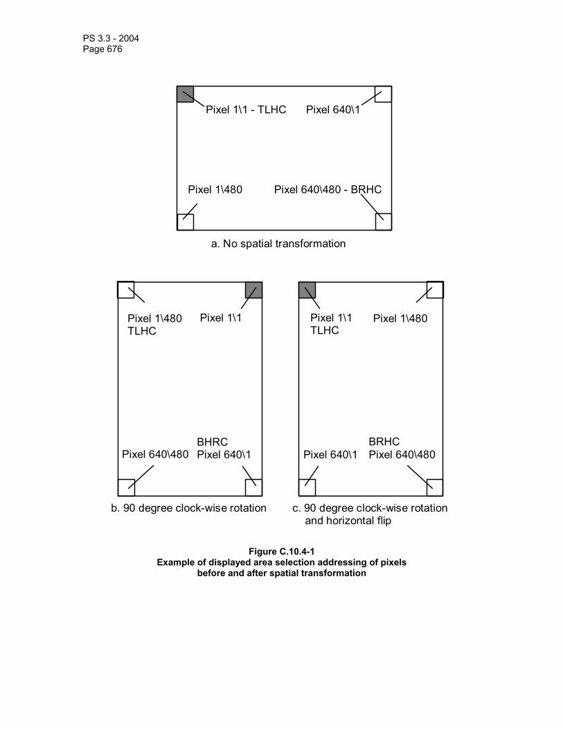
PS 3.3 - 2004 Page 676
Pixel 1\1 - TLHC
Pixel 640\480 - BRHC
a. No spatial transformation
Pixel 640\1
Pixel 1\480
Pixel 1\1
Pixel 640\480
b. 90 degree clock-wise rotation
BHRC Pixel 640\1
Pixel 1\480 TLHC
c. 90 degree clock-wise rotation and horizontal flip
Pixel 1\1TLHC
BRHC Pixel 640\480
Pixel 640\1
Pixel 1\480
Figure C.10.4-1 Example of displayed area selection addressing of pixels
before and after spatial transformation

PS 3.3 - 2004 Page 677
C.10.5 Graphic Annotation Module This Module defines Attributes of vector graphics and text annotation that shall be made available by a display device to be applied to an image. The graphics and text are defined in position and size relative to the image pixel coordinates or the Specified Displayed Area space (defined in C.10.4 Displayed Area Module). A Graphic Annotation shall be related to an Image.
Note: This Module uses a Sequence of Items rather than a Repeating Group (such as the Curve Repeating Group) to avoid limiting the maximum number of annotation items that may be present. The use of a Repeating Group would limit the number of items to 16. The use of Repeating Groups is also noted in PS 3.5 to be deprecated.
Table C.10-5
GRAPHIC ANNOTATION MODULE ATTRIBUTES Attribute Name Tag Type Attribute Description Graphic Annotation Sequence (0070,0001) 1 A sequence of Items each of which
represents a group of annotations composed of graphics or text or both. One or more Items shall be present.
>Referenced Image Sequence (0008,1140) 1C Sequence of Repeating Items where each Item provides reference to a selected set of Image SOP Class/SOP Instance pairs that are defined in the Presentation State Module. Required if a sequence item is present, and if graphic annotations in this Item do not apply to all the images listed in the Presentation State Module.
>>Referenced SOP Class UID (0008,1150) 1C Uniquely identifies the referenced SOP Class. Required if sequence item is present.
>>Referenced SOP Instance UID (0008,1155) 1C Uniquely identifies the referenced SOP Instance. Required if sequence item is present.
>>Referenced Frame Number (0008,1160) 1C Identifies the frame numbers within the referenced SOP Instance to which this group of annotations applies. Required if sequence item is present and the referenced image is a multi-frame image and the annotations do not apply to all frames.
>Graphic Layer (0070,0002) 1 The layer defined in the Graphic Layer Module C.10.7 in which the graphics or text is to be rendered.
>Text Object Sequence (0070,0008) 1C Sequence that describes a text annotation. One or more Items may be present. Either one or both of Text Object Sequence (0070,0008) or Graphic Object Sequence (0070,0009) are required if the Sequence Item is present.
>>Bounding Box Annotation Units (0070,0003) 1C Units of measure for the axes of the text

PS 3.3 - 2004 Page 678
bounding box. Defines whether or not the annotation is Image or Displayed Area relative. Both dimensions shall have the same units. Enumerated Values: PIXEL = Image relative position specified with sub-pixel resolution such that the origin at the Top Left Hand Corner (TLHC) of the TLHC pixel is 0.0\0.0, the Bottom Right Hand Corner (BRHC) of the TLHC pixel is 1.0\1.0, and the BRHC of the BRHC pixel is Columns\Rows (see figure C.10.5-1). The values must be within the range 0\0 to Columns\Rows. DISPLAY = Fraction of Specified Displayed Area where 0.0\0.0 is the TLHC and 1.0\1.0 is the BRHC. The values must be within the range 0.0 to 1.0. Required if Bounding Box Top Left Hand Corner (0070,0010) or Bounding Box Bottom Right Hand Corner (0070,0011) is present.
>>Anchor Point Annotation Units (0070,0004) 1C Units of measure for the axes of the text anchor point annotation. Enumerated Values for Anchor Point Annotation Units (0070,0004) are the same as for Bounding Box Annotation Units (0070,0003). Required if Anchor Point (0070,0014) is present.
>>Unformatted Text Value (0070,0006) 1 Text data which is unformatted and whose manner of display within the defined bounding box or relative to the specified anchor point is implementation dependent. See C.10.5.1.1. The text value may contain spaces, as well as multiple lines separated by either LF, CR, CR LF or LF CR, but otherwise no format control characters (such as horizontal or vertical tab and form feed) shall be present, even if permitted by the Value Representation of ST. The text shall be interpreted as specified by Specific Character Set (0008,0005) if present in the SOP Common Module.
Note: The text may contain single or multi-byte characters and use code extension techniques as described in PS 3.5 if permitted by the values of Specific Character Set (0008,0005).

PS 3.3 - 2004 Page 679
>>Bounding Box Top Left Hand Corner
(0070,0010) 1C Location of the Top Left Hand Corner (TLHC) of the bounding box in which Unformatted Text Value (0070,0006) is to be displayed, in Bounding Box Annotation Units (0070,0003), given as column\row. Column is the horizontal offset and row is the vertical offset. Required if Anchor Point (0070,0014) is not present.
>>Bounding Box Bottom Right Hand Corner
(0070,0011) 1C Location of the Bottom Right Hand Corner (BRHC) of the bounding box in which Unformatted Text Value (0070,0006) is to be displayed, in Bounding Box Annotation Units (0070,0003), given as column\row. Column is the horizontal offset and row is the vertical offset. Required if Anchor Point (0070,0014) is not present.
>>Bounding Box Text Horizontal Justification
(0070,0012) 1C Location of the text relative to the vertical edges of the bounding box. Enumerated Values: LEFT = closest to left edge RIGHT = closest to right edge CENTER = centered Required if Bounding Box Top Left Hand Corner (0070,0010) is present.
>>Anchor Point (0070,0014) 1C Location of a point in the image or Specified Displayed Area to which the Unformatted Text Value (0070,0006) is related, in Anchor Point Annotation Units (0070,0004), given as column\row. Column is the horizontal offset and row is the vertical offset. Required if Bounding Box Top Left Hand Corner (0070,0010) and Bounding Box Bottom Right Hand Corner (0070,0011) are not present. May be present even if a bounding box is specified (i.e. Bounding Box Top Left Hand Corner (0070,0010) and Bounding Box Bottom Right Hand Corner (0070,0011) are present).
>>Anchor Point Visibility (0070,0015) 1C Flag to indicate whether or not a visible indication (such as a line or arrow) of the relationship between the text and the anchor point is to be displayed. Enumerated Values: Y = yes N = no Required if Anchor Point (0070,0014) is present.

PS 3.3 - 2004 Page 680
>Graphic Object Sequence (0070,0009) 1C Sequence that describes a graphic annotation. One or more Items may be present. Either one or both of Text Object Sequence (0070,0008) or Graphic Object Sequence (0070,0009) are required if the Sequence Item is present.
>>Graphic Annotation Units (0070,0005) 1 Units of measure for the axes of the graphic annotation. Enumerated Values for Graphic Annotation Units (0070,0005) are the same as for Bounding Box Annotation Units (0070,0003).
>>Graphic Dimensions (0070,0020) 1 Enumerated Value: 2 >>Number of Graphic Points (0070,0021) 1 Number of data points in this graphic. >> Graphic Data (0070,0022) 1 Coordinates that specify this graphic
annotation. See C.10.5.1.2 for further explanation.
>>Graphic Type (0070,0023) 1 The shape of graphic that is to be drawn. See C.10.5.1.2. Enumerated Values: POINT POLYLINE INTERPOLATED CIRCLE ELLIPSE
>>Graphic Filled (0070,0024) 1C Whether or not the closed graphics element is displayed as filled (in some unspecified manner that shall be distinguishable from an outline) or as an outline. See C.10.5.1.2. Enumerated Values: Y = yes N = no Required if Graphic Data (0070,0022) is “closed”, that is Graphic Type (0070,0023) is CIRCLE or ELLIPSE, or Graphic Type (0070,0023) is POLYLINE or INTERPOLATED and the first data point is the same as the last data point.
C.10.5.1 Graphic Annotation Attribute Descriptions C.10.5.1.1 Unformatted Text Value The text shall be displayed if any part of the bounding box or anchor point is within the Specified Display Area.
The text need not be confined to within the bounding box, but shall be rendered in a direction from the Top Left Hand Corner (TLHC) of the bounding box to the Bottom Right Hand Corner

PS 3.3 - 2004 Page 681
(BRHC) of the bounding box, even if these coordinates have been specified in an image relative space and then transformed (rotated, flipped or scaled).
Notes: 1. An implementation may render text outside the confines of the bounding box if necessary to display all the specified text.
2. Alternatively, an implementation may choose to render the text in a scrolling box, or a link to another fixed or popup window as appropriate.
Whether the contents of the bounding box completely opacify the underlying image or whether the box is “transparent” is undefined.
Notes: 1. For example, an implementation may choose an “exclusive or” style opacification to be sure that the text is discernible over light and dark portions of the image.
2. Commonly, the region of the bounding box around the text will be rendered “transparently”, i.e. the image will be visible, though some implementations may choose to opacify the bounding box behind the text to improve its readability.
An alternative to specifying a bounding box, is to specify an Anchor Point (0070,0014), i.e. some point in an image or Specified Displayed Area that is related to the text. The semantics of this relationship, and the manner of positioning or linking the text to this point, are unspecified.
Notes: 1. For example, a description of a feature may be linked to a point in the image, and when that image is displayed, if it is magnified and panned, the rendered text (and any arrow or line drawn in response to Anchor Point Visibility (0070,0015)) might be repositioned as appropriate so as not to be cropped out of the Specified Displayed Area.
2. As another example, the text could be rendered in a pop-up window when a hypertext link flagged on the displayed image at the location of the Anchor Point (0070,0014) is selected.
3. The bounding box and anchor point need not be defined with the same axis units, i.e. one can be image pixel relative, and the other displayed area relative.
The size, font and rotation of the individual rendered text characters are unspecified.
C.10.5.1.2 Graphic Data and Graphic Type Graphic Data (0070,0022) contains the points in the graphic annotation, each dimension for the first point, followed by dimensions for second point, etc. For a two dimensional curve: X1, Y1, X2, Y2, etc. The first (X) dimension corresponds to the image or Specified Displayed Area column (horizontal offset), and the second (Y) dimension corresponds to the image or Specified Displayed Area row (vertical offset). The Value Representation of all components of the N-tuple shall be the same. The image or Specified Displayed Area relative drawing space is defined in Graphic Annotation Units (0070,0005).
If Graphic Type (0070,0023) is POINT, then two values (one point) shall be specified and the single point specified is to be drawn.
If Graphic Type (0070,0023) is POLYLINE, then the points are to be interpreted as an n-tuple list of end points between which straight lines are to be drawn.
If Graphic Type (0070,0023) is INTERPOLATED, then the points are to be interpreted as an n-tuple list of end points between which some form of implementation dependent curved lines are to be drawn. The rendered line shall pass through all the specified points.
If Graphic Type (0070,0023) is CIRCLE, then exactly two points shall be present; the first point is to be interpreted as the center and the second point as a point on the circumference of a circle, some form of implementation dependent representation of which is to be drawn.

PS 3.3 - 2004 Page 682
If Graphic Type (0070,0023) is ELLIPSE, then exactly four points shall be present; the first two points are to be interpreted as the endpoints of the major axis and the second two points as the endpoints of the minor axis of an ellipse, some form of implementation dependent representation of which is to be drawn.
The notion of “open” or “closed” has no inherent meaning in the context of an arbitrary graphic, other than in the condition for the presence of Graphic Filled (0070,0024). The graphic has no semantic notion of an associated observation such as a region of interest, except that which the unformatted text in the same Item may describe.
The choice of pixel value used to represent the graphic on a display is defined in the Graphic Layer Module C.10.7.

PS 3.3 - 2004 Page 683
Pixel 1\1Point 0.0\0.0
Point 511.0\511.0 Pixel 512\512
Point 512.0\512.0
Point 1.0\1.0
Example for the case where Columns(0028,0010) = 512 and Rows
(0028,0011) = 512
Figure C.10.5-1 Sub-pixel Addressing Units in PIXEL Space
C.10.6 Spatial Transformation Module This Module defines a manner of rotating an image by increments of ninety degrees and flipping an image.
Table C.10-6 SPATIAL TRANSFORMATION MODULE ATTRIBUTES
Attribute Name Tag Type Attribute Description Image Rotation (0070,0042) 1 How far to rotate the image clockwise in
degrees, before any Image Horizontal Flip (0070,0041) is applied. Enumerated Values: 0, 90,180,270
Notes: Negative values are not permitted since the Value Representation is unsigned.
Image Horizontal Flip (0070,0041) 1 Whether or not to flip the image horizontally after any Image Rotation has been applied such that the left side of the image becomes the right side.

PS 3.3 - 2004 Page 684
Enumerated Values: Y = yes, N = no
Note: No vertical flip is specified since the same result can be achieved by a combination of a 180 degree rotation and a horizontal flip.
Note: Given the definition of the Grayscale Transformation Sequence in PS 3.4, it is apparent that the rotation, flipping and magnification will be applied AFTER the application of any bit-mapped overlays or graphic annotations that are specified in the image pixel spaces, but BEFORE the application of graphic annotations that apply in the Specified Displayed Area relative space.
C.10.7 Graphic Layer Module This Module defines the characteristics of the layers in which curves, overlays, graphic and text may be rendered.
Layers group together graphics which are related. It is recommended that a layer be displayed such that it may be distinguished from other layers that have a different value for Graphic Layer Order (0070,0062).
Note: The transparency, opacity, and any other interaction (such as exclusive or) with underlying layers or image data are not specified and are at the discretion of the implementation.

PS 3.3 - 2004 Page 685
Table C.10-7 GRAPHIC LAYER MODULE ATTRIBUTES
Attribute Name Tag Type Attribute Description Graphic Layer Sequence (0070,0060) 1 A sequence of Items each of which
represents a single layer in which overlays, curves, graphics or text may be rendered. An Item is required for each layer referenced from the Graphic Annotation Module or the Overlay/Curve Activation Module.
>Graphic Layer (0070,0002) 1 A string which identifies the layer. Note: This identifier may be used by other
Attributes within the same presentation state instance to reference this layer. There is no requirement for the same identifiers to be used in different presentation states, and there is no mechanism for referencing layers in other presentation states. That is, a UID is not required.
>Graphic Layer Order (0070,0062) 1 An integer indicating the order in which it is recommended that the layer be rendered, if the display is capable of distinguishing. Lower numbered layers are to be rendered first.
>Graphic Layer Recommended Display Grayscale Value
(0070,0066) 3 A default single gray unsigned value in which it is recommended that the layer be rendered on a monochrome display. The units are specified in P-Values from a minimum of 0000H (black) up to a maximum of FFFFH (white).
Note: The maximum P-Value for this Attribute may be different from the maximum P-Value from the output of the Presentation LUT, which may be less than 16 bits in depth.
>Graphic Layer Recommended Display RGB Value
(0070,0067) 3 A triplet of unsigned RGB values in which it is recommended that the layer be rendered on a color display. The minimum intensity displayable is specified as 0000H\0000H\0000H (black) and the maximum intensity displayable as FFFFH\FFFFH\FFFFH (white).
>Graphic Layer Description (0070,0068) 3 A free text description of the contents of this layer.

PS 3.3 - 2004 Page 686
C.10.8 Waveform Identification Module The table in this section contains Attributes that identify a Waveform as a separate information entity.
Table C.10-8 Waveform Identification Module Attributes
Attribute Name Tag Type Attribute Description Instance Number (0020,0013) 1 A number that identifies this Waveform. Content Date (0008,0023) 1 The date the Waveform data was created. Content Time (0008,0033) 1 The time the Waveform data was created. Acquisition Datetime (0008,002A) 1 The date and time that the acquisition of data that
resulted in this waveform started; the reference timestamp for the Multiplex Group Time Offset (0018,1068) for a waveform multiplex group
Note: The synchronization of this time with an external clock is specified in the Synchronization Module in Acquisition Time Synchronized (0018,1800).
Referenced Instance Sequence
(0008,114A) 3 A sequence which provides reference to a set of SOP Class/Instance pairs significantly related to this Waveform. One or more Items may be included in this sequence.
>Referenced SOP Class UID (0008,1150) 1C Uniquely identifies the referenced SOP Class. Required if a Sequence Item is present.
>Referenced SOP Instance UID
(0008,1155) 1C Uniquely identifies the referenced SOP Instance. Required if a Sequence Item is present.
Note: The Acquisition Datetime (0008,002A) is the time of the original waveform data capture. Derived waveforms which are processed (e.g., averaged or filtered) and encoded subsequent to the waveform Acquisition Datetime have a Content Date (0008,0023) and Content Time (0008,0033) representing the time of the processing. In all cases the actual date and time of creation of the SOP Instance for transmission or storage may be recorded in the Instance Creation Date (0008,0012) and Instance Creation Time (0008,0013) (see Section C.12.2).
C.10.9 Waveform Module The table in this section contains Attributes that describe a time-based waveform. A waveform consists of one or more multiplex groups, each encoded into an Item in the Waveform Sequence. All channels within a multiplex group are synchronously digitized at a common sampling frequency.
Table C.10-9 Waveform Module Attributes
Attribute Name Tag Type Attribute Description Waveform Sequence (5400,0100) 1 Sequence of one or more Items, each representing
one waveform multiplex group. Ordering of Items in this Sequence is significant for external reference to specific multiplex groups.
> Multiplex Group Time Offset (0018,1068) 1C Offset time in milliseconds from a reference time (see C.10.9.1.1). Required if Acquisition Time Synchronized

PS 3.3 - 2004 Page 687
(0018,1800) value is Y; may be present otherwise. > Trigger Time Offset (0018,1069) 1C Offset time in milliseconds from a synchronization
trigger to the first sample of a waveform multiplex group. May be positive or negative. Required if waveform acquisition is synchronized to a trigger.
> Trigger Sample Position (0018,106E) 3 Sample number whose time corresponds to a synchronization trigger (see C.10.9.1.2).
> Waveform Originality (003A,0004) 1 See C.10.9.1.3. Enumerated values: ORIGINAL DERIVED
> Number of Waveform Channels
(003A,0005) 1 Number of channels for this multiplex group.
> Number of Waveform Samples
(003A,0010) 1 Number of samples per channel in this multiplex group.
> Sampling Frequency (003A,001A) 1 Frequency in Hz > Multiplex Group Label (003A,0020) 3 Label for multiplex group > Channel Definition Sequence (003A,0200) 1 Sequence of one or more Items, with one Item per
channel (see C.10.9.1.4). Ordering of Items in this Sequence is significant for reference to specific channels.
>> Waveform Channel Number (003A,0202) 3 Equipment physical channel number used for acquisition.
>> Channel Label (003A,0203) 3 Text label for channel which may be used for display purposes
>> Channel Status (003A,0205) 3 One or more values for the status of this channel within this SOP Instance. Defined terms: OK TEST DATA DISCONNECTED QUESTIONABLE INVALID UNCALIBRATED UNZEROED Precise location of a change in status may be noted in an Annotation.
>> Channel Source Sequence (003A,0208) 1 A coded descriptor of the waveform channel source (metric, anatomical position, function, and technique). Only a single Item shall be permitted in this sequence. (See C.10.9.1.4.1)
>>> Include 'Code Sequence Macro' Table 8.8-1. Baseline Context ID determined by IOD specialization >> Channel Source Modifiers Sequence
(003A,0209) 1C Sequence of one or more Items which further qualify the Waveform Source. Required if Channel Source Sequence (003A,0208) does not fully specify the semantics of the source. Ordering of Items in this Sequence may be semantically significant.
>>> Include 'Code Sequence Macro' Table 8.8-1. Baseline Context ID determined by IOD specialization >> Source Waveform Sequence
(003A,020A) 3 A sequence which provides reference to a DICOM waveform from which this channel was derived. One or

PS 3.3 - 2004 Page 688
more Items may be included in this Sequence. >>>Referenced SOP Class UID
(0008,1150) 1C Identifies the referenced SOP Class. Required if a Sequence Item is present.
>>>Referenced SOP Instance UID
(0008,1155) 1C Identifies the referenced SOP Instance. Required if a Sequence Item is present.
>>> Referenced Waveform Channels
(0040,A0B0) 1C Identifies the waveform multiplex group and channel within the referenced SOP Instance. Pair of values (M,C). Required if a Sequence Item is present.
>> Channel Derivation Description
(003A,020C) 3 Additional description of waveform channel derivation
>> Channel Sensitivity (003A,0210) 1C Nominal numeric value of unit quantity of sample. Required if samples represent defined (not arbitrary) units.
>> Channel Sensitivity Units Sequence
(003A,0211) 1C A coded descriptor of the Units of measure for the Channel Sensitivity. Only a single Item shall be permitted in this sequence. (see C.10.9.1.4.2) Required if Channel Sensitivity (003A,0210) is present.
>>> Include 'Code Sequence Macro' Table 8.8-1. Defined Context ID = 3082 >> Channel Sensitivity Correction Factor
(003A,0212) 1C Multiplier to be applied to encoded sample values to match units specified in Channel Sensitivity (003A,0210) (e.g., based on calibration data) (see C.10.9.1.4.2) Required if Channel Sensitivity (003A,0210) is present.
>> Channel Baseline (003A,0213) 1C Offset of encoded sample value 0 from actual 0 using the units defined in the Channel Sensitivity Units Sequence (003A,0211). Required if Channel Sensitivity (003A,0210) is present.
>> Channel Time Skew (003A,0214) 1C Offset of first sample of channel from waveform multiplex group start time, in seconds (see C.10.9.1.4.3) Required if Channel Sample Skew is not present.
>> Channel Sample Skew (003A,0215) 1C Offset of first sample of channel from waveform multiplex group start time, in samples (see C.10.9.1.4.3) Required if Channel Time Skew is not present.
>> Channel Offset (003A,0218) 3 Additional offset of first sample of channel to be used in aligning multiple channels for presentation or analysis, in seconds (see C.10.9.1.4.3)
>> Waveform Bits Stored (003A,021A) 1 Number of significant bits within the waveform samples (see C.10.9.1.4.4)
>> Filter Low Frequency (003A,0220) 3 Nominal 3dB point of lower frequency of pass band; in Hz
>> Filter High Frequency (003A,0221) 3 Nominal 3dB point of upper frequency of pass band; in Hz
>> Notch Filter Frequency (003A,0222) 3 Center frequency of notch filter(s); in Hz >> Notch Filter Bandwidth (003A,0223) 3 Nominal 3dB bandwidth of notch filter(s); in Hz >> Channel Minimum Value (5400,0110) 3 Minimum valid sample value as limited by the

PS 3.3 - 2004 Page 689
acquisition equipment (see C.10.9.1.4.5) >> Channel Maximum Value (5400,0112) 3 Maximum valid sample value as limited by the
acquisition equipment (see C.10.9.1.4.5) > Waveform Bits Allocated (5400,1004) 1 Size of each waveform data sample within the
Waveform Data; see section C.10.9.1.5 > Waveform Sample Interpretation
(5400,1006) 1 Data representation of the waveform data points. See C.10.9.1.5.
> Waveform Padding Value (5400,100A) 1C Value of waveform samples inserted in channels when input is absent or invalid. Required if acquisition equipment inserts padding. See C.10.9.1.6.
> Waveform Data (5400,1010) 1 Encoded data samples - channel multiplexed See section C.10.9.1.7
C.10.9.1 Waveform Attribute Descriptions C.10.9.1.1 Multiplex Group Time Offset Multiplex Group Time Offset (0018,1068) specifies the offset time in milliseconds from a reference time to the first sample of the multiplex group. The reference time is the Acquisition Datetime (0008,002A), if present in the SOP Instance.
In all other cases, the offset is from an arbitrary reference time that is the same for all Multiplex Groups in the SOP Instance; i.e., the Multiplex Group Time Offset allows only relative time synchronization between Multiplex Groups in the SOP Instance. The arbitrary reference time may nominally be assumed to be the Content Time (0008,0033).
C.10.9.1.2 Trigger Sample Position The Trigger Sample Position (0018,106E) specifies the sample which was digitized at the same time as a synchronization trigger. Sample positions are enumerated by channel, with the first sample enumerated 1. This provides a single trigger sample location for all channels of the multiplex group. Although channels may not have been sampled synchronously (as specified by Channel Time Skew or Channel Sample Skew), for the purpose of determining the location of the trigger with an integer value position, all channels are considered to be synchronous.
C.10.9.1.3 Waveform Originality Waveform Originality (003A,0004) shall have the value ORIGINAL if the Waveform Data samples are the original or source data, and shall have the value DERIVED if the Waveform Data samples have been derived in some manner from the sample data of other waveforms.
Notes : 1. The Waveform Originality (003A,0004) attribute is comparable to the Image Type (0008,0008) attribute value 1 (see C.7.6.1.1.2). Within a single Multiplex Group, all channels shall have the same Originality value.
2. Waveform data which has been transcoded from a non-DICOM format may have Waveform Originality value ORIGINAL if the samples are unchanged from the originally acquired waveform samples.
C.10.9.1.4 Channel Definition Sequence C.10.9.1.4.1 Channel Source and Modifiers Channel Source Sequence (003A,0208) identifies the metric (quality being measured, e.g., voltage or pressure), the anatomical position of the sensor or probe, the function of the channel (e.g., measurement or stimulus), and any particulars of technique which affect those parameters (e.g., pull-back across multiple anatomic sites, or differential input from two distinct sites). If the full semantics of the source is not carried in a single coded entry (e.g., if it specifies the location

PS 3.3 - 2004 Page 690
but not the metric), additional qualifiers are identified in Channel Source Modifiers Sequence (003A,0209) coded entries.
When a single sensor channel is used to collect a waveform from two (or more) anatomic sites, e.g., in hemodynamic pull-back procedures, multiple Channel Source Modifier items will identify the sequence of sites, if not encoded in the semantics of the Channel Source Coded Entry. Transition times from one site to another may be indicated with an Annotation, or pull-back rate may be indicated with an Acquisition Context Sequence Item (see Section C.7.6.14).
The Baseline (default) Context IDs are defined by IOD in accordance with Section A.34. Restrictions in the IOD may also determine the pattern of specification of the waveform source, i.e., which item is to be encoded in the Channel Source sequence, and the order in which Channel Source Modifier items are to be encoded. Unless otherwise specified, pattern of specification of the waveform source shall be:
1. If the function of the channel is not measurement, the function (and optionally additional parameters of the channel source) shall be encoded in the Channel Source item.
2. If the function of the channel is measurement of a waveform originating in the patient (the implicit default function), the metric (and optionally additional parameters of the channel source) shall be encoded in the Channel Source item.
3. If not encoded in the Channel Source item, and a particular technique needs to be encoded, that technique shall be encoded in the first Channel Source Modifier item.
Note: For example, an intracardiac measurement of a pressure waveform across the mitral valve by means of a catheter pullback may be encoded in one of the following three ways (using pseudo-coded terminology), depending on the availability of coded terms with sufficient expressive power:
Channel Source Channel Source Modifiers X-2311 “pressure measurement” T-7663 “pullback”
C-2001 “mitral valve” X-2123 “pressure measurement, pullback” C-2001 “mitral valve” X-1234 “pressure measurement, mitral valve, pullback” (none required)
C.10.9.1.4.2 Channel Sensitivity and Channel Sensitivity Units Channel Sensitivity is the nominal value of one unit (i.e., the least significant bit) of each waveform sample in the Waveform Data attribute (5400,1010). It includes both the amplifier gain and the analog-digital converter resolution. It does not relate the vertical scaling of a waveform on a particular display.
Note: The Defined (default) Context Group for Channel Sensitivity Units Sequence is CID 3082 Waveform Units of Measurement, which includes all the commonly used measurement values. Units of measurement not included in the default list can be specified using the more general CID 82 Units of Measurement, or a local Coding Scheme. The Defined Context ID may be replaced in a specialization of the IOD.
Channel Sensitivity Correction Factor (003A,0212) is the ratio of the actual (calibrated) value to the nominal Channel Sensitivity specified in Data Element (003A,0210). Thus a waveform sample value multiplied by the Channel Sensitivity value provides the nominal measured value in Channel Sensitivity Units, and that nominal value multiplied by the Channel Sensitivity Correction Factor provides the calibrated measured value.

PS 3.3 - 2004 Page 691
C.10.9.1.4.3 Channel Skew and Channel Offset Skew is also known as a sub-sample time delay, typically caused by using a multiplexed analog to digital converter which switches from channel to channel. For analysis it may be important to know if the analog channels were all latched simultaneously or sequentially and then digitized. Skew may be represented as time offset in seconds, or a fractional number of samples.
Separate and additional to skew is an offset time adjustment (sometimes called latency) by which one waveform channel is displaced significantly relative to others before sampling.
Note: As an example, a hemodynamic pressure is measured at the external end of a catheter, and thus its measurement is delayed by the time for the pressure wave to propagate down the catheter. With a dual catheter measurement, two signals may be acquired at the same time, but one arrives by a longer distance (e.g., a pulmonary capillary wedge pressure, compared to a left ventricular pressure). To obtain an accurate comparison of the waveforms (e.g., the gradient across the mitral valve), one waveform has to be offset (perhaps as much as 30 ms) to synchronize them.
C.10.9.1.4.4 Waveform Bits Stored Waveform Bits Stored (003A,021A) specifies the number of significant bits within the Waveform Bits Allocated of each sample, for signed or unsigned integers.
If Waveform Sample Value Representation is MB or AB, Waveform Bits Stored shall be 8.
C.10.9.1.4.5 Channel Minimum and Maximum Value Channel Minimum and Maximum Value attributes (5400,0110) and (5400,0112) may be used to send the analog-to-digital converter limits (i.e., the clipping levels).
Note: These values do not represent the maximum and minimum values in the data set, but rather the valid range of values.
C.10.9.1.5 Waveform Bits Allocated and Waveform Sample Interpretation Waveform Bits Allocated (5400,1004) specifies the number of bits allocated for each sample, and Waveform Sample Interpretation (5400,1006) specifies the data representation of each waveform sample. Waveform Bits Allocated shall be a multiple of 8. These data elements are related, and their defined terms are specified in Table C.10-5.
Table C.10-10 Waveform Bits Allocated and Waveform Sample Interpretation
Waveform Bits Allocated - Defined Terms
Waveform Sample Interpretation - Defined Terms
Waveform Sample Interpretation Meaning
8 SB signed 8 bit linear UB unsigned 8 bit linear MB 8 bit mu-law (in accordance with ITU-T Recommendation G.711) AB 8 bit A-law (in accordance with ITU-T Recommendation G.711) 16 SS signed 16 bit linear US unsigned 16 bit linear
Notes: 1. The set of valid values from within this table may be constrained by definition of the IOD (see Section A.34). 2. mu-law and A-law encoding is without the alternate bit inversion used for PCM transmission through the telephone network.

PS 3.3 - 2004 Page 692
This representation also applies to the Channel Minimum and Maximum Data Values, and Waveform Padding Value.
C.10.9.1.6 Waveform Padding Value Equipment which produces digitized waveform curves may encode a specific value when the source is disconnected or otherwise invalid. This value is encoded like the Waveform Data attribute with one sample only.
The Waveform Padding Value need not be within the range specified by the Channel Minimum and Maximum Data Values.
C.10.9.1.7 Waveform Data Each sample shall be encoded using the defined Waveform Sample Interpretation (5400,1006), using the defined number of Waveform Bits Stored (003A,021A) right justified in the sample. If the number of Waveform Bits Stored is less than the number of bits in Waveform Bits Allocated, the sign bit shall be extended to the highest order bit of the data sample.
Data values are encoded interleaved, incrementing by channel and then by sample (i.e., C1S1, C2S1,C3S1, ... CnS1, C1S2, C2S2, C3S2, ... CnSm), with no padding or explicit delimitation between successive samples. Cx denotes the channel defined in the Channel Definition Sequence Item in item number x.
Notes: 1. With 8-bit Waveform Data, there may be an odd number of channels and an odd number of samples; see PS3.5 for rules on encoding.
2. The sign bit extension rule differs from the rules for pixel data, which do not require sign extension.
C.10.10 Waveform Annotation Module The table in this section contains Attributes that identify annotations to the waveform of the current SOP Instance. Each annotation conceptually forms the equivalent of a overlay on a presentation display of the annotated entity. Annotations may represent a measurement or categorization based on the waveform data, identification of regions of interest or particular features of the waveform, or events during the data collection which may affect diagnostic interpretation (e.g., the time at which the subject coughed).
Each Annotation Item shall have the following components:
1. An annotation Text, Coded Name (only), Coded Name/Coded Value pair, or Coded Name/Numeric Measurement pair (mutually exclusive)
2. Temporal coordinates in the Waveform to which the annotation applies
Table C.10-11 – Waveform Annotation Module Attributes Attribute Name Tag Type Attribute Description Waveform Annotation Sequence
(0040,B020) 1 Sequence of Annotation Items; one or more items shall be present
> Unformatted Text Value (0070,0006) 1C Text Observation Value (annotation). Mutually exclusive with Concept Name Code Sequence (0040,A043)
> Concept Name Code Sequence
(0040,A043) 1C Code representing the fully specified name of the NUMERIC measurement or CODED concept. This sequence shall contain exactly one item.

PS 3.3 - 2004 Page 693
Mutually exclusive with Text Value (0070,0006).>>Include 'Code Sequence Macro' Table 8.8-1 Baseline Context ID may be defined in IOD
definition. >> Modifier Code Sequence (0040,A195) 1C A sequence of items modifying or specializing
the Concept Name. Any number of items may be present. Required if Concept Name Code Sequence (0040,A043) is sent and the value does not fully describe the semantics of the measurement or concept.
>>>Include 'Code Sequence Macro' Table 8.8-1 Baseline Context ID may be defined in IOD definition.
> Concept Code Sequence (0040,A168) 3 A sequence that conveys the categorical coded nominal value.
>>Include 'Code Sequence Macro' Table 8.8-1 Baseline Context ID may be defined in IOD definition.
>> Modifier Code Sequence (0040,A195) 1C A sequence of items modifying or specializing the Concept. Any number of items may be present. Required if Concept Code Sequence (0040,A168) is sent and the value does not fully describe the semantics of the concept value.
>>>Include 'Code Sequence Macro' Table 8.8-1 Baseline Context ID may be defined in IOD definition.
> Numeric Value (0040,A30A) 3 Numeric measurement value or values. > Measurement Units Code Sequence
(0040,08EA) 3 Units of measurement. Coded entry sequence with one item only.
>> Include 'Code Sequence Macro' Table 8.8-1 Baseline Context ID 82 > Referenced Waveform Channels
(0040,A0B0) 1 List of channels in waveform to which annotation applies. See C.10.10.1.1
> Temporal Range Type (0040,A130) 1C See C.10.10.1.2 for Enumerated Values. Required if Annotation does not apply to entire Referenced Waveform Channels; shall not be present if Annotation applies to entire temporal extent of referenced channels.
> Referenced Sample Positions
(0040,A132) 1C List of samples within a multiplex group specifying temporal points for annotation. Position of first sample is 1. Required if Temporal Range Type (0040,A130) is present, and if Referenced Time Offsets (0040,A138) and Referenced Datetime (0040,A13A) are not present. See C.10.10.1.3
> Referenced Time Offsets (0040,A138) 1C Specifies temporal points for annotation by number of seconds after start of data. Required if Temporal Range Type (0040,A130) is present, and if Referenced Sample Positions (0040,A132) and Referenced Datetime (0040,A13A) are not present.

PS 3.3 - 2004 Page 694
> Referenced Datetime (0040,A13A) 1C Specifies temporal points for annotation by absolute time. Required if Temporal Range Type (0040,A130) is present, and if Referenced Sample Positions (0040,A132) and Referenced Time Offsets (0040,A138) are not present.
> Annotation Group Number (0040,A180) 3 Number identifying associated annotations (see C.10.10.1.4).
C.10.10.1 Waveform Annotation Attribute Descriptions C.10.10.1.1 Referenced Channels Referenced Waveform Channels (0040,A0B0) is a multi-value attribute which lists the channels to which an annotation of a waveform applies. Each channel is specified as a pair of values (M,C), where the first value is the ordinal of the sequence item of the Waveform Sequence (5400,0100) attribute (i.e., the Multiplex Group Number), and the second value is the ordinal of the sequence item of the Channel Definition Sequence (003A,0200) attribute (i.e., the Waveform Channel Number) within the multiplex group.
If the specified channel number is 0, the annotation applies to all channels in the multiplex group.
Note: As an example, an annotation which applies to the entire first multiplex group and channels 2 and 3 of the third multiplex group would have Referenced Channels value 0001 0000 0003 0002 0003 0003.
C.10.10.1.2 Temporal Range Type The Temporal Range Type attribute (0040,A130) defines the type of temporal extent of the annotated region of interest. A temporal point (or instant of time) may be defined by a waveform sample offset (for a single waveform multiplex group only), time offset, or absolute time.
The following terms are Enumerated Values for Temporal Range Type:
POINT = a single temporal point MULTIPOINT = multiple temporal points SEGMENT = a range between two temporal points MULTISEGMENT = multiple segments, each denoted by two temporal points BEGIN = a range beginning at one temporal point, and extending beyond the end of the acquired data END = a range beginning before the start of the acquired data, and extending to (and including) the identified temporal point
C.10.10.1.3 Referenced Sample Positions Referenced Sample Positions (0040,A132) may be used only if Referenced Waveform Channels (0040,A0B0) refers to channels within a single multiplex group. The sample position is by channel, and applies to all channels specified in Referenced Channels (0040,A0B0).
C.10.10.1.4 Annotation Group Number The Annotation Group Number (0040,A180) allows the logical association of multiple annotations within the current SOP Instance. Such linked annotations share an Annotation Group Number, but each annotation is semantically separable. The nature of the association is not defined. The number is not semantically significant.
Note: For instance, the R-wave in several waveform channels may be annotated, and all occurrences of the same R-wave could be linked in an annotation group.

PS 3.3 - 2004 Page 695
C.11 LOOK UP TABLES
C.11.1 Modality LUT Module Table C.11-1 specifies the Attributes that describe the Modality LUT.
Either a Modality LUT Sequence containing a single Item or Rescale Slope and Intercept values shall be present but not both.
Note: This requirement for only a single transformation makes it possible to unambiguously define the input of succeeding stages of the grayscale pipeline such as the VOI LUT.
Table C.11-1 MODALITY LUT MODULE ATTRIBUTES
Attribute Name Tag Type Attribute Description Modality LUT Sequence (0028,3000) 1C Defines a sequence of Modality LUTs.
Only one Item may be present. Shall not be present if Rescale Intercept (0028,1052) is present.
>LUT Descriptor (0028,3002) 1C Specifies the format of the LUT Data in this Sequence. See C.11.1.1 for further explanation. Required if the Modality LUT Sequence (0028,3000) is sent.
>LUT Explanation (0028,3003) 3 Free form text explanation of the meaning of the LUT.
>Modality LUT Type (0028,3004) 1C Specifies the output values of this Modality LUT. See C.11.1.1.2 for further explanation. Required if the Modality LUT Sequence (0028,3000) is sent.
>LUT Data (0028,3006) 1C LUT Data in this Sequence. Required if the Modality LUT Sequence (0028,3000) is sent.
Rescale Intercept (0028,1052) 1C The value b in relationship between stored values (SV) and the output units specified in Rescale Type (0028,1054). Output units = m*SV + b. Required if Modality LUT Sequence (0028,3000) is not present. Shall not be present otherwise.
Rescale Slope (0028,1053) 1C m in the equation specified by Rescale Intercept (0028,1052). Required if Rescale Intercept is present.
Rescale Type (0028,1054) 1C Specifies the output units of Rescale Slope (0028,1053) and Rescale Intercept (0028,1052). See C.11.1.1.2 for further explanation.
PS 3.3 - 2004 Page 696
Required if Rescale Intercept is present.
C.11.1.1 LUT Attribute Descriptions C.11.1.1.1 LUT descriptor The three values of the LUT Descriptor (0028,3002) describe the format of the LUT Data in the corresponding Data Element (0028,3006).
The first value is the number of entries in the lookup table. When the number of table entries is equal to 216 then this value shall be 0.
The second value is the first stored pixel value mapped. The Value Representation of the second value (US or SS) is specified by Pixel Representation (0028,0103). This stored pixel value is mapped to the first entry in the LUT. All stored pixel values less than the first value mapped are also mapped to the first entry in the LUT Data. A stored pixel value one greater than the first value mapped is mapped to the second entry in the LUT Data. Subsequent stored pixel values are mapped to the subsequent entries in the LUT Data up to a stored pixel value equal to number of entries + first value mapped - 1 which is mapped to the last entry in the LUT Data. Stored pixel values greater than or equal to number of entries + first value mapped are also mapped to the last entry in the LUT Data.
The third value specifies the number of bits for each entry in the LUT Data. It shall take the value 8 or 16. The LUT Data shall be stored in a format equivalent to 8 or 16 bits allocated where the high bit is equal to bits allocated - 1.
The third value also conveys the range of LUT entry values. It shall take the value 8 or 16, corresponding with the LUT entry value range of 256 or 65536.
Note: Since the LUT Descriptor (0028,3002) Attribute is multi-valued, in an Explicit VR Transfer Syntax, only one value representation (US or SS) may be specified, even though the first and third values are always by definition interpreted as unsigned. The explicit VR actually used is dictated by the VR needed to represent the second value, which will be consistent with Pixel Representation (0028,0103).
The LUT Data contains the LUT entry values.
The output range of the Modality LUT Module depends on whether or not Rescale Slope (0028,1053) and Rescale Intercept (0028,1052) or the Modality LUT Sequence (0028,3000) are used.
In the case where Rescale Slope and Rescale Intercept are used, the output ranges from (minimum pixel value*Rescale Slope+Rescale Intercept) to (maximum pixel value*Rescale Slope+Rescale Intercept), where the minimum and maximum pixel values are determined by Bits Stored and Pixel Representation.
Note: This range may be signed even if Pixel Representation is unsigned.
In the case where the Modality LUT Sequence is used, the output range is from 0 to 2n-1 where n is the third value of LUT Descriptor. This range is always unsigned.
C.11.1.1.2 Modality LUT and Rescale Type Specifies the units of the output of the Modality LUT or rescale operation.
Defined Terms:
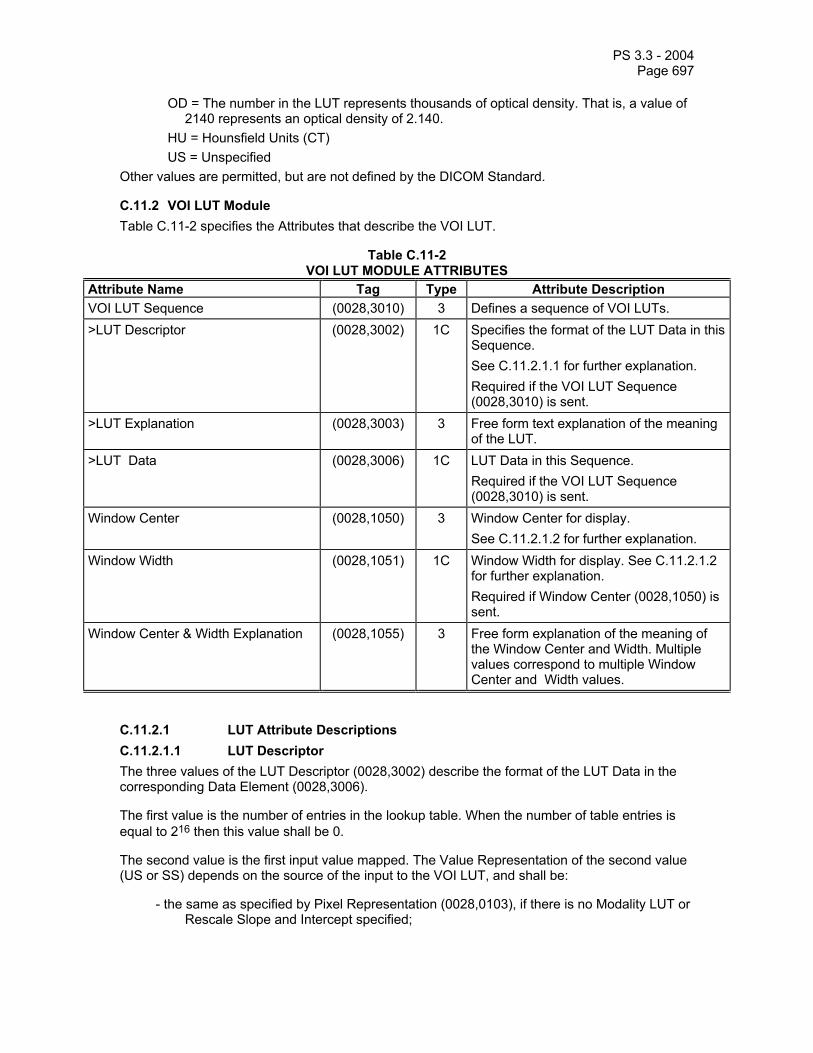
PS 3.3 - 2004 Page 697
OD = The number in the LUT represents thousands of optical density. That is, a value of 2140 represents an optical density of 2.140.
HU = Hounsfield Units (CT) US = Unspecified
Other values are permitted, but are not defined by the DICOM Standard.
C.11.2 VOI LUT Module Table C.11-2 specifies the Attributes that describe the VOI LUT.
Table C.11-2 VOI LUT MODULE ATTRIBUTES
Attribute Name Tag Type Attribute Description VOI LUT Sequence (0028,3010) 3 Defines a sequence of VOI LUTs. >LUT Descriptor (0028,3002) 1C Specifies the format of the LUT Data in this
Sequence. See C.11.2.1.1 for further explanation. Required if the VOI LUT Sequence (0028,3010) is sent.
>LUT Explanation (0028,3003) 3 Free form text explanation of the meaning of the LUT.
>LUT Data (0028,3006) 1C LUT Data in this Sequence. Required if the VOI LUT Sequence (0028,3010) is sent.
Window Center (0028,1050) 3 Window Center for display. See C.11.2.1.2 for further explanation.
Window Width (0028,1051) 1C Window Width for display. See C.11.2.1.2 for further explanation. Required if Window Center (0028,1050) is sent.
Window Center & Width Explanation (0028,1055) 3 Free form explanation of the meaning of the Window Center and Width. Multiple values correspond to multiple Window Center and Width values.
C.11.2.1 LUT Attribute Descriptions C.11.2.1.1 LUT Descriptor The three values of the LUT Descriptor (0028,3002) describe the format of the LUT Data in the corresponding Data Element (0028,3006).
The first value is the number of entries in the lookup table. When the number of table entries is equal to 216 then this value shall be 0.
The second value is the first input value mapped. The Value Representation of the second value (US or SS) depends on the source of the input to the VOI LUT, and shall be:
- the same as specified by Pixel Representation (0028,0103), if there is no Modality LUT or Rescale Slope and Intercept specified;

PS 3.3 - 2004 Page 698
- SS if the possible output range after application of the Rescale Slope and Intercept may be signed;
Note: This is always the case for the CT Image IOD in which the Rescale Type is specified to be Hounsfield Units, which are always signed.
- US otherwise.
This input value is mapped to the first entry in the LUT. All input values less than the first value mapped are also mapped to the first entry in the LUT Data. An input value one greater than the first value mapped is mapped to the second entry in the LUT Data. Subsequent input values are mapped to the subsequent entries in the LUT Data up to an input value equal to number of entries + first value mapped - 1 which is mapped to the last entry in the LUT Data. Input values greater than or equal to number of entries + first value mapped are also mapped to the last entry in the LUT Data.
The third value specifies the number of bits for each entry in the LUT Data. If the VOI LUT is included in an Image IOD, the third value of LUT Descriptor (0028,3002) shall be 8 or 16 bits, unless otherwise specialized. If the VOI LUT is included in a Presentation State IOD, the third value of LUT Descriptor (0028,3002) shall be between 8 and 16 inclusive. The LUT Data shall be stored in a format equivalent to 8 or 16 bits allocated where the high bit is equal to bits stored - 1, where bits stored is the third value.
Note: Since the LUT Descriptor (0028,3002) Attribute is multi-valued, in an Explicit VR Transfer Syntax, only one value representation (US or SS) may be specified, even though the first and third values are always by definition interpreted as unsigned. The explicit VR actually used is dictated by the VR needed to represent the second value.
The LUT Data contains the LUT entry values.
The output range is from 0 to 2n-1 where n is the third value of LUT Descriptor. This range is always unsigned.
C.11.2.1.2 Window center and window width Window Center (0028,1050) and Window Width (0028,1051) specify a linear conversion from stored pixel values (after any Modality LUT or Rescale Slope and Intercept specified in the IOD have been applied) to values to be displayed. Window Center contains the input value that is the center of the window. Window Width contains the width of the window.
Note: The terms “window center” and “window width” are not consistently used in practice, nor were they defined in previous versions of the standard. The definitions here are presented for the purpose of defining consistent meanings for identity and threshold transformations while preserving the common practice of using integral values for center and width.
Window Width (0028,1051) shall always be greater than or equal to 1.
When Window Width (0028,1051) is greater than 1, these Attributes select the range of input values that are to be mapped to the full range of the displayed output.
When Window Width (0028,1051) is equal to 1, they specify a threshold below which input values will be displayed as the minimum output value.
Note: Whether the minimum output value is rendered as black or white may depend on the value of Photometric Interpretation (0028,0004) or the presence of a Presentation LUT Module.

PS 3.3 - 2004 Page 699
These Attributes are applied according to the following pseudo-code, where x is the input value, y is an output value with a range from ymin to ymax, c is Window Center (0028,1050) and w is Window Width (0028,1051):
if (x <= c - 0.5 - (w-1)/2), then y = ymin
else if (x > c - 0.5 + (w-1)/2), then y = ymax,
else y = ((x - (c - 0.5)) / (w-1) + 0.5) * (ymax - ymin)+ ymin
Notes: 1. For the purpose of this definition, a floating point calculation without integer truncation is assumed, though the manner of implementation may vary as long as the result is the same.
2. The pseudo-code function computes a continuous value over the output range without any discontinuity at the boundaries. The value of 0 for w is expressly forbidden, and the value of 1 for w does not cause division by zero, since the continuous segment of the function will never be reached for that case.
3. For example, for an output range 0 to 255: c=2048, w=4096 becomes: if (x <= 0) then y = 0 else if (x > 4095) then y = 255 else y = ((x - 2047.5) / 4095 + 0.5) * (255-0) + 0 c=2048, w=1 becomes: if (x <= 2047.5) then y = 0 else if (x > 2047.5) then y = 255 else /* not reached */ c=0, w=100 becomes: if (x <= -50) then y = 0 else if (x > 49) then y = 255 else y = ((x + 0.5) / 99 + 0.5) * (255-0) + 0 c=0, w=1 becomes: if (x <= -0.5) then y = 0 else if (x > -0.5) then y = 255 else /* not reached */ 4. A Window Center of 2n-1 and a Window Width of 2n selects the range of input values from 0 to
2n-1. This represents an identity VOI LUT transformation in the case where no Modality LUT is specified and the stored pixel data are n bit unsigned integers.
5. A Window Width of 1 is typically used to represent a "threshold" operation in which those integer input values less than the Window Center are represented as the minimum displayed value and those greater than or equal to the Window Center are represented as the maximum displayed value. A Window Width of 2 will have the same result for integral input values.
6. The application of Window Center (0028,1050) and Window Width (0028,1051) may select a signed input range. There is no implication that this signed input range is clipped to zero.
7. The selected input range may exceed the actual range of the input values, thus effectively “compressing” the contrast range of the displayed data into a narrower band of the available contrast range, and “flattening” the appearance. There are no limits to the maximum value of the window width, or to the minimum or maximum value of window level, both of which may exceed the actual or possible range of input values.
8. Input values "below" the window are displayed as the minimum output value and input values "above" the window are displayed as the maximum output value. This is the common usage of
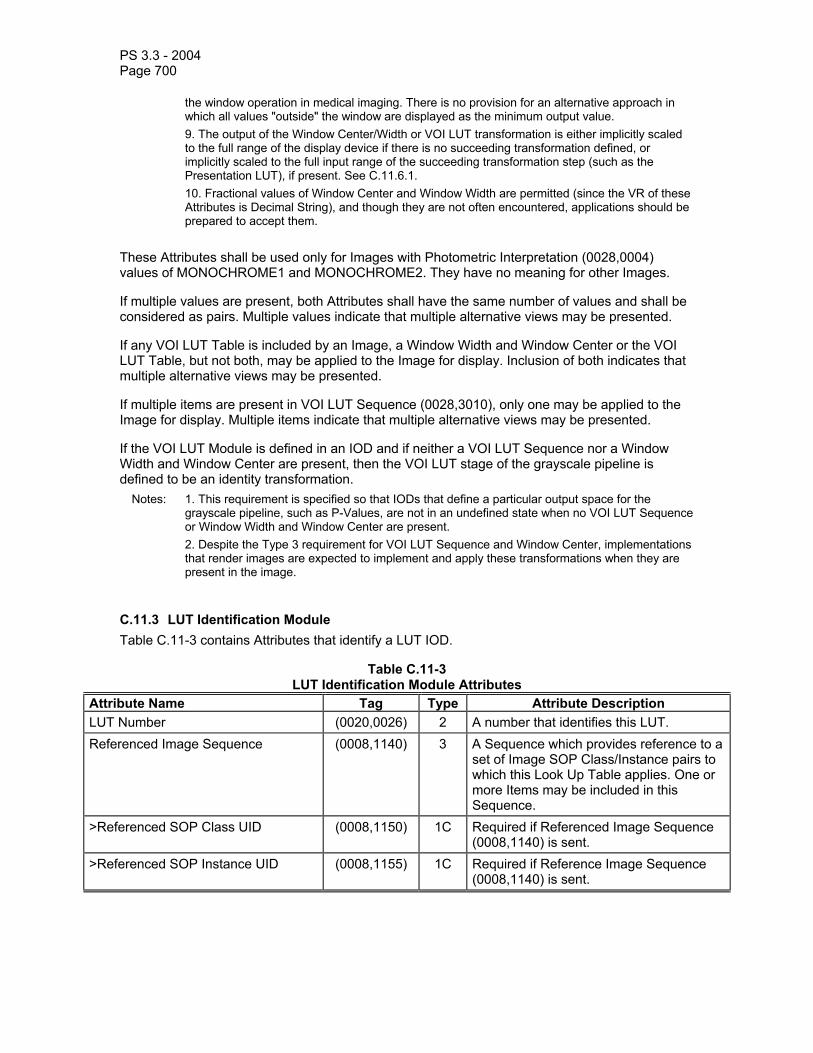
PS 3.3 - 2004 Page 700
the window operation in medical imaging. There is no provision for an alternative approach in which all values "outside" the window are displayed as the minimum output value.
9. The output of the Window Center/Width or VOI LUT transformation is either implicitly scaled to the full range of the display device if there is no succeeding transformation defined, or implicitly scaled to the full input range of the succeeding transformation step (such as the Presentation LUT), if present. See C.11.6.1.
10. Fractional values of Window Center and Window Width are permitted (since the VR of these Attributes is Decimal String), and though they are not often encountered, applications should be prepared to accept them.
These Attributes shall be used only for Images with Photometric Interpretation (0028,0004) values of MONOCHROME1 and MONOCHROME2. They have no meaning for other Images.
If multiple values are present, both Attributes shall have the same number of values and shall be considered as pairs. Multiple values indicate that multiple alternative views may be presented.
If any VOI LUT Table is included by an Image, a Window Width and Window Center or the VOI LUT Table, but not both, may be applied to the Image for display. Inclusion of both indicates that multiple alternative views may be presented.
If multiple items are present in VOI LUT Sequence (0028,3010), only one may be applied to the Image for display. Multiple items indicate that multiple alternative views may be presented.
If the VOI LUT Module is defined in an IOD and if neither a VOI LUT Sequence nor a Window Width and Window Center are present, then the VOI LUT stage of the grayscale pipeline is defined to be an identity transformation.
Notes: 1. This requirement is specified so that IODs that define a particular output space for the grayscale pipeline, such as P-Values, are not in an undefined state when no VOI LUT Sequence or Window Width and Window Center are present.
2. Despite the Type 3 requirement for VOI LUT Sequence and Window Center, implementations that render images are expected to implement and apply these transformations when they are present in the image.
C.11.3 LUT Identification Module Table C.11-3 contains Attributes that identify a LUT IOD.
Table C.11-3 LUT Identification Module Attributes
Attribute Name Tag Type Attribute Description LUT Number (0020,0026) 2 A number that identifies this LUT. Referenced Image Sequence (0008,1140) 3 A Sequence which provides reference to a
set of Image SOP Class/Instance pairs to which this Look Up Table applies. One or more Items may be included in this Sequence.
>Referenced SOP Class UID (0008,1150) 1C Required if Referenced Image Sequence (0008,1140) is sent.
>Referenced SOP Instance UID (0008,1155) 1C Required if Reference Image Sequence (0008,1140) is sent.

PS 3.3 - 2004 Page 701
C.11.4 Presentation LUT Module Table C.11-4 specifies the Attributes that describe the Presentation LUT.
Table C.11-4 Presentation LUT Module
Attribute name Tag Description Presentation LUT Sequence (2050,0010) Defines a sequence of Presentation LUTs. Only a single
item shall be included in this sequence. >LUT Descriptor (0028,3002) Specifies the format of the LUT Data in this Sequence.
Required if Presentation LUT Sequence (2050,0010) is sent. See C.11.4.1 for further explanation.
>LUT Explanation (0028,3003) Free form text explanation of the meaning of the LUT. >LUT Data (0028,3006) LUT Data in this Sequence. Presentation LUT Shape (2050,0020) Specifies pre-defined Presentation LUT shapes.
Enumerated Values : IDENTITY = input to the Presentation LUT is in P-Values, no further translation is necessary. LIN OD = input to Presentation LUT is in linear optical density over the range of Min Density (2010,0120) and Max Density (2010,1030).
Note: LIN OD is only defined for hardcopy devices and is not applicable to softcopy devices.
C.11.4.1 LUT Descriptor The three values of the LUT Descriptor (0028,3002) describe the format of the data in LUT Data (0028,3006).
The first value is the number of entries in the lookup table. When the number of table entries is equal to 216 then this value shall be 0. The number of entries shall be equal to the number of possible values in the input. (For 8 bit input will be 256 entries, for 12 bit input it will be 4096 entries)
The second value is the first input value mapped, and shall always be 0. The Value Representation of the second value is always US. This input value is mapped to the first entry in the LUT. Subsequent input values are mapped to the subsequent entries in the LUT Data up to an input value equal to number of entries + first value mapped - 1 which is mapped to the last entry in the LUT Data. There are no input values greater than number of entries – 1.
The third value specifies the number of bits for each entry in the LUT Data. It shall be between 10 and 16 inclusive. The LUT Data shall be stored in a format equivalent to 16 bits allocated where the high bit is equal to bits stored - 1, where bits stored is the third value.
Note: Since the LUT Descriptor (0028,3002) Attribute is multi-valued, in an Explicit VR Transfer Syntax, only one value representation (US or SS) may be specified. Since all three values are always by definition interpreted as unsigned, the explicit VR actually used will always be US.
LUT Data (0028,3006) contains the LUT entry values, which are P-Values.

PS 3.3 - 2004 Page 702
The output range is from 0 to 2n-1 where n is the third value of LUT Descriptor. This range is always unsigned.
This range specifies the output range of the P-Values.
C.11.5 Image Histogram Module Table C.11.5-1
IMAGE HISTOGRAM MODULE ATTRIBUTES Attribute name Tag Type Description
Histogram Sequence (0060,3000) 1 Defines a sequence of Histograms. One or more Items may be included in this Sequence.
>Histogram Number of Bins (0060,3002) 1C The number of “bins” (entries) in the histogram. Required if a Sequence Item is present.
>Histogram First Bin Value (0060,3004) 1C The stored pixel value corresponding to the lowest pixel value counted in the first bin. All image pixel values less than this value are not included in the histogram. Required if a Sequence Item is present.
Note: The Value Representation of this Attribute is determined by the value of Pixel Representation (0028,0103).
>Histogram Last Bin Value (0060,3006) 1C The stored pixel value corresponding to the highest pixel value counted in the last bin. All image pixel values greater than this value are not included in the histogram. Required if a Sequence Item is present.
Note: The Value Representation of this Attribute is determined by the value of Pixel Representation (0028,0103).
>Histogram Bin Width (0060,3008) 1C The number of consecutive stored pixel values included in a bin. All bins shall be of equal width. Required if a Sequence Item is present.
>Histogram Explanation (0060,3010) 3 Free form text explanation of the meaning of the LUT.
>Histogram Data (0060,3020) 1C Histogram Data encoded as 32 bit unsigned counts of the number of pixel values in each bin. Required if a Sequence Item is present.
C.11.5.1 Image Histogram Attribute Descriptions The Image Histogram is a multi-valued sequence representing a sequential count of binned stored image pixel values in ascending order.

PS 3.3 - 2004 Page 703
Note: One reason to include a histogram with an image is as an aid to image processing applications. For applications that use them, computations of histograms for very large images can be a significant burden on computer resources and can seriously degrade the response time to the user.
The Image Histogram is multi-valued to support multiple histograms per image. One or more regions of interest or value ranges may be separately computed. A description of the region(s) of interest and value range may be included in the Histogram Explanation (0060,3010). The Image Histogram may be related to parts or all of a specific image.
The Attributes describing the parameters of the histogram are in image pixel value space, as stored in Pixel Data (7FE0,0010), before the application of any transformation such as Rescale Slope and Intercept or Modality LUT.
The range of stored image pixel value instances is described by the Histogram First Bin Value (0060,3004) and Histogram Last Bin Value (0060,3006). All values outside of this range shall be ignored. The number of histogram bins shall be large enough to contain all of the pixels in the range from the smallest to the largest stored image pixel value in that region of the image from which the histogram has been derived (which may or may not be the whole image).
The Histogram Bin Width (0060,3008) describes how many consecutive stored image pixel values are counted as one. All bins shall be of equal width.
Note: For example, a Histogram Bin Width (0060,3008) of 8 means that counts of pixel values in ascending groups of 8 are added together. If Histogram First Bin Value (0060,3004) were 0, then the first bin would contain the count of pixel values in the range of 0-7, the second bin the count of pixel values in the range of 8-15, etc. If Histogram Number of Bins (0060,3002) were 32, then the last bin would contain the count of pixel values in the range of 248-255 and Histogram Last Bin Value (0060,3006) would be 255 (not 248).
This example is illustrated in the following figure, in which the vertical axis represents the count within each bin and the horizontal axis represents each bin in ascending order.
Histogram Last Bin Value (0060,3006) = 255
Histogram First Bin Value (0060,3004) = 0
Count of zero in the last bin indicates no values in the
image between 248 and 255
Histogram Number of Bins (0060,3002) defines 32 bins
Histogram Bin Width (0060,3008) = 8, so the first bin includes
values between 0 and

PS 3.3 - 2004 Page 704
C.11.6 Softcopy Presentation LUT Module Table C.11.6-1 specifies the Attributes that describe the Softcopy Presentation LUT.
Table C.11.6-1 SOFTCOPY PRESENTATION LUT MODULE ATTRIBUTES
Attribute name Tag Type Description Presentation LUT Sequence (2050,0010) 1C Defines a sequence of Presentation LUTs.
Only a single item shall be included in this sequence. Required if Presentation LUT Shape (2050,0020) is absent.
>LUT Descriptor (0028,3002) 1C Specifies the format of the LUT Data in this Sequence. See C.11.6.1.1 for further explanation. Required if a Sequence Item is present.
>LUT Explanation (0028,3003) 3 Free form text explanation of the meaning of the LUT.
>LUT Data (0028,3006) 1C LUT Data in this Sequence. Required if a Sequence Item is present.
Presentation LUT Shape (2050,0020) 1C Specifies predefined Presentation LUT transformation. Required if Presentation LUT Sequence (2050,0010) is absent. Enumerated Values: IDENTITY - no further translation necessary, input values are P-Values INVERSE - output values after inversion are P-Values See C.11.6.1.2.
Note: This Module differs from the Presentation LUT Module used in the hardcopy (print) related SOP
Classes in that Optical Density is not supported for Presentation LUT Shape (since Optical Density has no meaning for softcopy display devices).
C.11.6.1 Softcopy Presentation LUT Attributes When the Presentation LUT is specified as a Presentation LUT Sequence, then the input range of values is specified by the LUT Descriptor as the first value mapped and the number of entries (values mapped). However, there is an implicit linear scaling of the output range of the preceding transformation (such as the VOI LUT transformation) so that it is always mapped to the specified input range of the Presentation LUT.
When the Presentation LUT is specified as Presentation LUT Shape, then the input range is implicitly specified to be the output range of the preceding transformation (VOI LUT, or if the VOI LUT is identity or absent, the Modality LUT, or if the Modality LUT and VOI LUT are identity or absent, the stored pixel values). In this case, the full range of the output of the preceding transformation will be mapped to the full input range of the display device that receives the output of the Presentation LUT.
Note: The output of the preceding transformation may be signed. This does not mean that signed P-Values actually need to be generated, only that the output of the preceding transformation is to be interpreted by the display device as perceptually linear over the range from the minimum to the maximum values output by the preceding step, and that the minimum value be mapped to the lowest JND Index (and hence luminance) that the display can generate, and the maximum
PS 3.3 - 2004 Page 705
value be mapped to the highest JND Index (and hence luminance) that the display can generate.
In other words, in both cases, the Presentation LUT Module is always implicitly specified to apply over the full range of output of the preceding transformation, and it never selects a subset or superset of the that range (unlike the VOI LUT).
The output bit precision of the VOI LUT Sequence is not required to match the input range of the Presentation LUT Sequence.
Notes: 1. For example, if the VOI LUT is specified as a Window Center of 0 and a Window Width of 100, then the range from -50 to +49 is selected to be mapped to the full range of the display or print device (the full range of P-Values) if the Presentation LUT Shape is specified as IDENTITY or INVERSE. This example demonstrates the conventional understanding of the meaning of Window Center and Width to select “values of interest” that are to be displayed across the full range of the output device, without explicitly having to map each choice to P-Values.
2. For example, if the VOI LUT is specified as a Window Center of 0 and a Window Width of 100, and the Presentation LUT Sequence is sent with a LUT Descriptor first value of 256 and second value of 0, then the range from -50 to +49 is implicitly linearly scaled from 0 to 255 before selecting values from the LUT Data in the Presentation LUT Sequence. This example demonstrates that it is not necessary to send a different Presentation LUT for different Window Center and Width values.
3. For example, if the VOI LUT is specified as VOI LUT Sequence with a LUT Descriptor with a 3rd Value of 16, then the range from 0 to 216-1 is selected to be mapped to the full range of the display or print device (the full range of P-Values) if the Presentation LUT Shape is specified as IDENTITY or INVERSE. This example demonstrates that a VOI LUT may be specified with the desired precision, without having to explicitly send a Presentation LUT to rescale that precision to whatever range of P-Values is preferred by the display application.
4. For example, if the VOI LUT is specified as VOI LUT Sequence with a LUT Descriptor with a 3rd Value of 16, and the Presentation LUT Sequence is sent with a LUT Descriptor first value of 4096 and second value of 0, then the range from 0 to 216-1 is implicitly linearly scaled to the range 0 to 4095 before selecting values from the LUT Data in the Presentation LUT Sequence. This example demonstrates the case where, to save space, the Presentation LUT is sent in a compact form that a display application may choose to interpolate more precisely, yet the VOI LUT output may be sent with 16 bit precision.
C.11.6.1.1 LUT Descriptor The three values of the LUT Descriptor (0028,3002) describe the format of the LUT Data in the corresponding Data Element (0028,3006).
The first value is the number of entries in the lookup table. When the number of table entries is equal to 216 then this value shall be 0.
The second value is the first implicitly scaled input value mapped, and shall always be 0. The Value Representation of the second value is always US. This implicitly scaled input value is mapped to the first entry in the LUT. There are no implicitly scaled input values less than the first value mapped. An implicitly scaled input value one greater than the first value mapped is mapped to the second entry in the LUT Data. Subsequent implicitly scaled input values are mapped to the subsequent entries in the LUT Data up to an implicitly scaled input value equal to number of entries + first value mapped - 1 which is mapped to the last entry in the LUT Data. There are no implicitly scaled input values greater than number of entries + first value mapped.
The third value specifies the number of bits for each entry in the LUT Data. The third value of the LUT Descriptor (0028,3002) shall be between 8 and 16 inclusive. The LUT Data shall be stored in a format equivalent to 8 or 16 bits allocated where the high bit is equal to bits stored - 1, where bits stored is the third value.

PS 3.3 - 2004 Page 706
Note: Since the LUT Descriptor (0028,3002) Attribute is multi-valued, in an Explicit VR Transfer Syntax, only one value representation (US or SS) may be specified. Since all three values are always by definition interpreted as unsigned, the explicit VR actually used will always be US.
The LUT Data contains the LUT entry values, which are P-Values.
The output range is from 0 to 2n-1 where n is the third value of LUT Descriptor. This range is always unsigned.
This range specifies the output range of the P-Values.
C.11.6.1.2 Presentation LUT Shape A value of INVERSE shall mean the same as a value of IDENTITY, except that the minimum output value shall convey the meaning of the maximum available luminance, and the maximum value shall convey the minimum available luminance. In other words:
P-Value = maximum value - output value
C.11.7 Overlay/Curve Activation Module This Module defines a manner of controlling whether or not bit-mapped overlay and curve information are displayed.
In the case of Curves, these Curves are contained within the referenced image(s).
Note: Curves may not be present within the Presentation State, since the same function is served by the Graphic Annotation Module which provides additional features.
In the case of Overlays, if the corresponding Overlay Group activated is present within the Presentation State, then that Overlay shall be activated and any corresponding Overlay in the referenced image(s) ignored, otherwise the Overlay within the referenced image(s) shall be activated.
An Overlay Group referenced in the Bitmap Display Shutter Module described in C.7.6.15 shall not be activated using the Overlay/Curve Activation Module.
Table C.11.7-1 specifies the Attributes that describe the Overlay/Curve Activation Module.
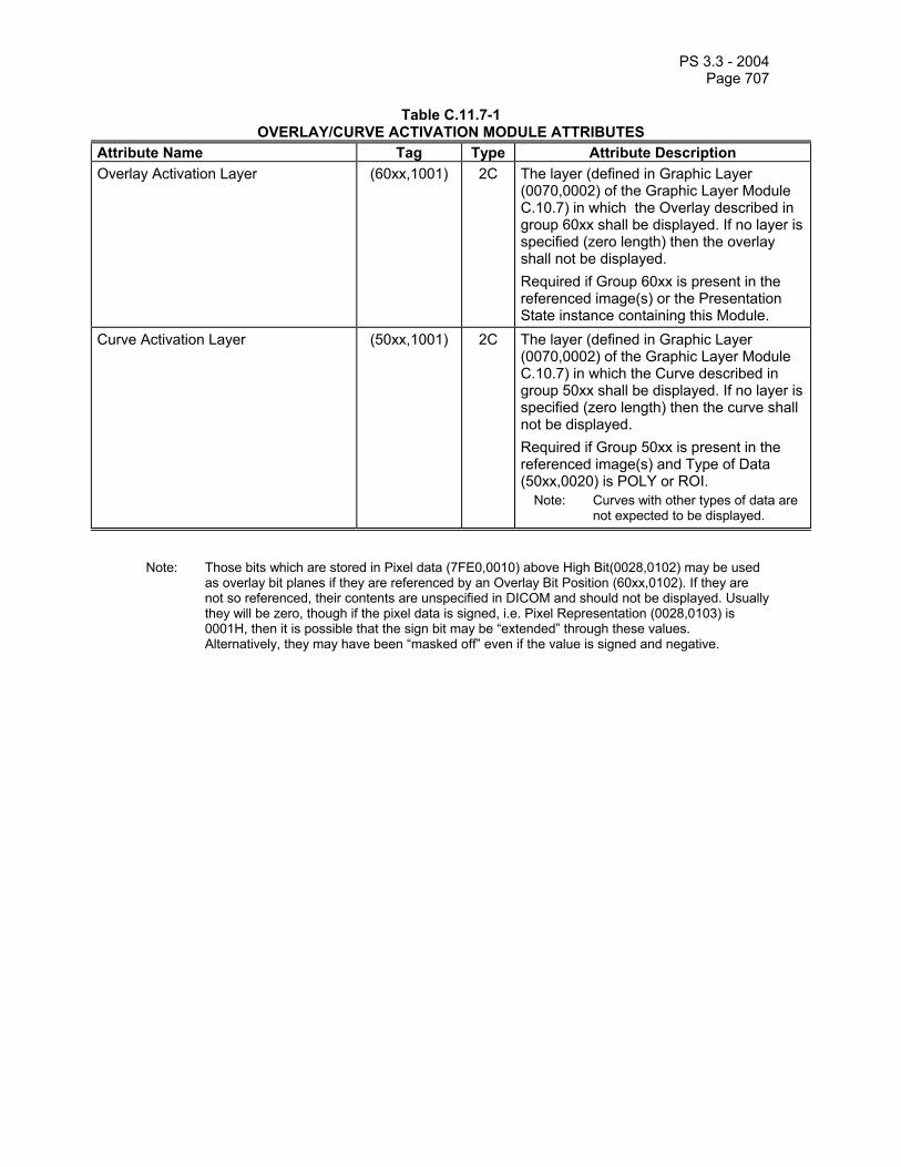
PS 3.3 - 2004 Page 707
Table C.11.7-1 OVERLAY/CURVE ACTIVATION MODULE ATTRIBUTES
Attribute Name Tag Type Attribute Description Overlay Activation Layer (60xx,1001) 2C The layer (defined in Graphic Layer
(0070,0002) of the Graphic Layer Module C.10.7) in which the Overlay described in group 60xx shall be displayed. If no layer is specified (zero length) then the overlay shall not be displayed. Required if Group 60xx is present in the referenced image(s) or the Presentation State instance containing this Module.
Curve Activation Layer (50xx,1001) 2C The layer (defined in Graphic Layer (0070,0002) of the Graphic Layer Module C.10.7) in which the Curve described in group 50xx shall be displayed. If no layer is specified (zero length) then the curve shall not be displayed. Required if Group 50xx is present in the referenced image(s) and Type of Data (50xx,0020) is POLY or ROI.
Note: Curves with other types of data are not expected to be displayed.
Note: Those bits which are stored in Pixel data (7FE0,0010) above High Bit(0028,0102) may be used as overlay bit planes if they are referenced by an Overlay Bit Position (60xx,0102). If they are not so referenced, their contents are unspecified in DICOM and should not be displayed. Usually they will be zero, though if the pixel data is signed, i.e. Pixel Representation (0028,0103) is 0001H, then it is possible that the sign bit may be “extended” through these values. Alternatively, they may have been “masked off” even if the value is signed and negative.

PS 3.3 - 2004 Page 708
C.11.8 Softcopy VOI LUT module Table C.11.8-1 specifies the Attributes that describe the Softcopy VOI LUT. These Attributes have the same meaning and behavior as defined in the VOI LUT Module Section C.11.2.
Table C.11.8-1 SOFTCOPY VOI LUT MODULE ATTRIBUTES
Attribute Name Tag Type Attribute Description Softcopy VOI LUT Sequence (0028,3110) 1 Defines a sequence of VOI LUTs or
Window Centers and Widths and to which images and frames they apply. No more than one VOI LUT Sequence containing a single Item or one pair of Window Center/Width values shall be specified for each image or frame. One or more Items shall be present.
>Referenced Image Sequence (0008,1140) 1C Sequence of Repeating Items where each Item provides reference to a selected set of Image SOP Class/SOP Instance pairs that are defined in the Presentation State Module. Required if a sequence item is present, and if the VOI LUT transformation in this Item does not apply to all the images listed in the Presentation State Module.
>>Referenced SOP Class UID (0008,1150) 1C Uniquely identifies the referenced SOP Class. Required if sequence item is present.
>>Referenced SOP Instance UID (0008,1155) 1C Uniquely identifies the referenced SOP Instance. Required if sequence item is present.
>>Referenced Frame Number (0008,1160) 1C Identifies the frame numbers within the referenced SOP Instance to which this VOI LUT or Window Center and Width applies. Required if sequence item is present and the referenced image is a multi-frame image and the VOI LUT or Window Center and Width does not apply to all frames.
>VOI LUT Sequence (0028,3010) 1C Defines a sequence of VOI LUTs. Only one Item may be present. Required if Window Center (0028,1050) is not present.
>>LUT Descriptor (0028,3002) 1C Specifies the format of the LUT Data in this Sequence. See C.11.2.1.1 for further explanation. Required if the VOI LUT Sequence (0028,3010) is sent.
>>LUT Explanation (0028,3003) 3 Free form text explanation of the meaning of the LUT.
>>LUT Data (0028,3006) 1C LUT Data in this Sequence. Required if the VOI LUT Sequence

PS 3.3 - 2004 Page 709
(0028,3010) is sent. >Window Center (0028,1050) 1C Window Center for display.
See C.11.2.1.2 for further explanation. Required if VOI LUT Sequence (0028,3010) is not present.
>Window Width (0028,1051) 1C Window Width for display. See C.11.2.1.2 for further explanation. Required if Window Center (0028,1050) is sent.
>Window Center & Width Explanation (0028,1055) 3 Free form explanation of the meaning of the Window Center and Width.
C.11.9 Presentation Series Module Table C.11.9-1 contains Attributes that identify and describe a Presentation Series.
Table C.11.9-1 PRESENTATION SERIES MODULE ATTRIBUTES
Attribute Name Tag Type Attribute Description Modality (0008,0060) 1 Type of equipment that originally acquired
the data. Enumerated Value: PR = Presentation State See C.7.3.1.1.1.
Note: This implies that presentation states will be in different series from the images to which they
apply, which will have different values for Modality.

PS 3.3 - 2004 Page 710
C.11.10 Presentation State Module Table C.11.10-1 contains Attributes that identify and describe a Presentation State.
Table C.11.10-1 PRESENTATION STATE MODULE ATTRIBUTES
Attribute Name Tag Type Attribute Description Instance Number (0020,0013) 1 A number that identifies this presentation
(SOP Instance). Note: In previous versions of the Standard
this Attribute was referred to as Image Number.
Content Label (0070,0080) 1 A label that is used to identify this presentation.
Note: This value may be used by an application as a Defined Term in order to imply some grouping of different presentation states, i.e. it may have the same value for different presentation state instances that share some common concept.
Content Description (0070,0081) 2 A description of this presentation. Presentation Creation Date (0070,0082) 1 Date on which this presentation was
created. Note: This date may be different from the
date that the DICOM SOP Instance was created, since the presentation state information contained may have been recorded earlier.
Presentation Creation Time (0070,0083) 1 Time at which this presentation was created.
Note: This time may be different from the time that the DICOM SOP Instance was created, since the presentation state information contained may have been recorded earlier.
Content Creator’s Name (0070,0084) 2 Name of operator saving the presentation state (such as a technologist or physician).
Referenced Series Sequence (0008,1115) 1 Sequence of Items where each Item includes the Attributes of one Series to which the Presentation applies. One or more Items shall be present.
>Series Instance UID (0020,000E) 1 Unique identifier of a Series that is part of the Study to which the Presentation applies, defined by Study Instance UID (0020,000D).
>Referenced Image Sequence (0008,1140) 1 Sequence of Items where each Item provides reference to a selected set of Image SOP Class/SOP Instance pairs to which the Presentation applies that are part of the Study defined by Study Instance UID (0020,000D) and the Series defined by

PS 3.3 - 2004 Page 711
Series Instance UID (0020,000E). >>Referenced SOP Class UID (0008,1150) 1 Uniquely identifies the referenced SOP
Class. Shall be the same for all Images referenced by this presentation state.
>>Referenced SOP Instance UID (0008,1155) 1 Uniquely identifies the referenced SOP Instance.
>>Referenced Frame Number (0008,1160) 1 Identifies the frame numbers within the referenced SOP Instance to which the presentation applies.
Note: This Attribute may be multi-valued.
Required if the referenced SOP Instance is a multi-frame image and the presentation does not apply to all frames.
Shutter Presentation Value (0018,1622) 1C The value used to replace those parts of the image occluded by the shutter, in P-Values. Required if the Display Shutter Module or Bitmap Display Shutter Module is present.
Note: The requirement in this module is type 1C which overrides the type 3 in the Display Shutter Module.
Mask Subtraction Sequence (0028,6100) 1C Required if Mask Module is present. Only one Item shall be present. Applicable Frame Range (0028,6102) shall not be included in the Sequence Item. See C.7.6.10 for a complete definition of the Attributes in the Items of this Sequence other than Mask Operation(0028,6101) and Applicable Frame Range (0028,6102).
Notes: 1. This Sequence is replicated here in order to specify one Item, additional conditions on Mask Operation (0028,6101) and to forbid Applicable Frame Range (0028,6102).
2. The role of Applicable Frame Range (0028,6102) is replaced by Referenced Frame Number (0008,1160).
>Mask Operation (0028,6101) 1 Type of mask operation to be performed Enumerated Values: AVG_SUB TID See C.7.6.10.1 for further explanation.
Note: The requirement in this module is for Enumerated Values which override the requirements of the Mask Module.
>Contrast Frame Averaging (0028,6112) 1C Specified the number of contrast frames to average together before performing the mask operation.

PS 3.3 - 2004 Page 712
Required if Mask Frame Numbers (0028,6110) specifies more than one frame (i.e. is multi-valued).
Note: The requirement in this module is conditional and overrides the optional requirements of the Mask Module.
Recommended Viewing Mode (0028,1090) 1C Specifies the recommended viewing protocol(s). Enumerated Value: SUB = for subtraction with mask images Required if Mask Subtraction Sequence (0028,6100) is present.
Note: The requirement in this module is type 1C and an Enumerated Value is specified which override the requirements of the Mask Module.

PS 3.3 - 2004 Page 713
C.12 GENERAL MODULES
The SOP Common Module shall be mandatory for all DICOM IODs.
C.12.1 SOP Common Module Table C.12-1 defines the Attributes which are required for proper functioning and identification of the associated SOP Instances. They do not specify any semantics about the Real-World Object represented by the IOD.
Table C.12-1 SOP COMMON MODULE ATTRIBUTES
Attribute Name Tag Type Attribute Description SOP Class UID (0008,0016) 1 Uniquely identifies the SOP Class. See
C.12.1.1.1 for further explanation. See also PS 3.4.
SOP Instance UID (0008,0018) 1 Uniquely identifies the SOP Instance. See C.12.1.1.1 for further explanation. See also PS 3.4.
Specific Character Set (0008,0005) 1C Character Set that expands or replaces the Basic Graphic Set. Required if an expanded or replacement character set is used. See C.12.1.1.2 for Defined Terms.
Instance Creation Date (0008,0012) 3 Date the SOP Instance was created. Instance Creation Time (0008,0013) 3 Time the SOP Instance was created. Instance Creator UID (0008,0014) 3 Uniquely identifies device which created
the SOP Instance. Related General SOP Class UID (0008,001A) 3 Uniquely identifies a Related General SOP
Class for the SOP Class of this Instance. See PS 3.4.
Original Specialized SOP Class UID
(0008,001B) 3 The SOP Class in which the Instance was originally encoded, but which has been replaced during a fall-back conversion to the current Related General SOP Class. See PS 3.4.
Coding Scheme Identification Sequence
(0008,0110) 3 Sequence of items that map values of Coding Scheme Designator (0008,0102) to an external coding system registration, or to a private or local coding scheme. One or more items may be present in the sequence.
>Coding Scheme Designator (0008,0102) 1 The value of a Coding Scheme Designator, used in this SOP Instance, which is being mapped.
>Coding Scheme Registry (0008,0112) 1C The name of the external registry where further definition of the identified coding scheme may be obtained. Required if coding scheme is registered. Defined term: HL7
>Coding Scheme UID (0008,010C) 1C The coding scheme UID identifier.

PS 3.3 - 2004 Page 714
Required if coding scheme is identified by an ISO 8824 object identifier compatible with the UI VR.
>Coding Scheme External ID (0008,0114) 2C The coding scheme identifier as defined in an external registry. Required if coding scheme is registered and Coding Scheme UID (0008,010C) is not present.
>Coding Scheme Name (0008,0115) 3 The coding scheme full common name >Coding Scheme Version (0008,0103) 3 The coding scheme version associated
with the Coding Scheme Designator (0008,0102).
>Responsible Organization (0008,0116) 3 Name of the organization responsible for the Coding Scheme. May include organizational contact information.
Timezone Offset From UTC (0008,0201) 3 Contains the offset from UTC to the timezone for all DA and TM Attributes present in this SOP Instance. Encoded as an ASCII string in the format “&ZZZZ”. The components of this string, from left to right, are & = “+” or “-”, and ZZZZ = Hours and Minutes of offset.
Notes: 1. This encoding is the same as described in PS 3.5 for the DT Value Representation.
2. This Attribute does not apply to values with a DT Value Representation, which may contain an explicitly encoded timezone.
3. The corrected time may cross a 24 hour boundary. For example, if Local Time = 1.00 a.m. and Offset = +0200, then UTC = 11.00 p.m. (23.00) the day before.
4. The “+” sign may not be omitted.
Time earlier than UTC is expressed as a negative offset.
Note: For example: UTC = 5.00 a.m. Local Time = 3.00 a.m. Offset = -0200
The local timezone offset is undefined if this Attribute is absent.
Contributing Equipment Sequence
(0018,A001) 3 Sequence of Items containing descriptive attributes of related equipment which has contributed to the acquisition, creation or modification of the composite instance. One or more Items may be included in this Sequence. See C.12.1.1.5 for further explanation.
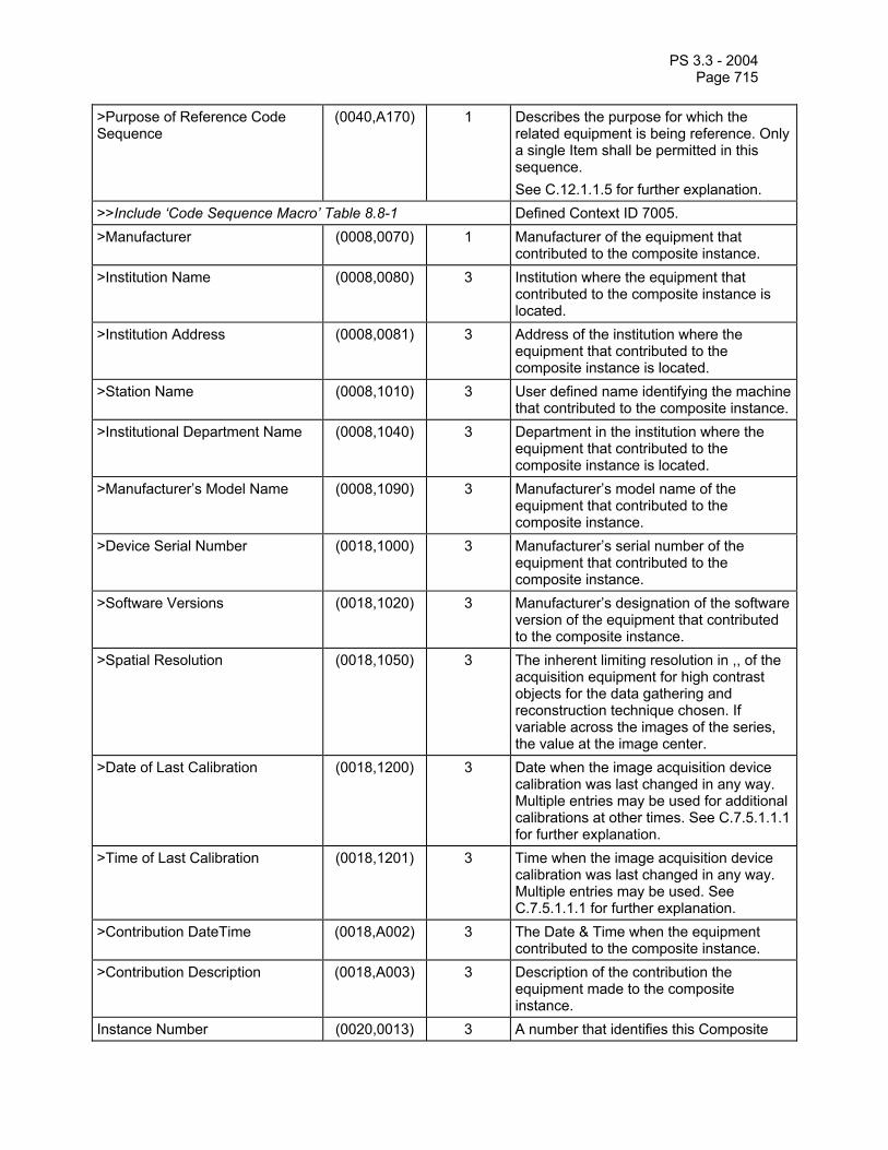
PS 3.3 - 2004 Page 715
>Purpose of Reference Code Sequence
(0040,A170) 1 Describes the purpose for which the related equipment is being reference. Only a single Item shall be permitted in this sequence. See C.12.1.1.5 for further explanation.
>>Include ‘Code Sequence Macro’ Table 8.8-1 Defined Context ID 7005. >Manufacturer (0008,0070) 1 Manufacturer of the equipment that
contributed to the composite instance. >Institution Name (0008,0080) 3 Institution where the equipment that
contributed to the composite instance is located.
>Institution Address (0008,0081) 3 Address of the institution where the equipment that contributed to the composite instance is located.
>Station Name (0008,1010) 3 User defined name identifying the machine that contributed to the composite instance.
>Institutional Department Name (0008,1040) 3 Department in the institution where the equipment that contributed to the composite instance is located.
>Manufacturer’s Model Name (0008,1090) 3 Manufacturer’s model name of the equipment that contributed to the composite instance.
>Device Serial Number (0018,1000) 3 Manufacturer’s serial number of the equipment that contributed to the composite instance.
>Software Versions (0018,1020) 3 Manufacturer’s designation of the software version of the equipment that contributed to the composite instance.
>Spatial Resolution (0018,1050) 3 The inherent limiting resolution in ,, of the acquisition equipment for high contrast objects for the data gathering and reconstruction technique chosen. If variable across the images of the series, the value at the image center.
>Date of Last Calibration (0018,1200) 3 Date when the image acquisition device calibration was last changed in any way. Multiple entries may be used for additional calibrations at other times. See C.7.5.1.1.1 for further explanation.
>Time of Last Calibration (0018,1201) 3 Time when the image acquisition device calibration was last changed in any way. Multiple entries may be used. See C.7.5.1.1.1 for further explanation.
>Contribution DateTime (0018,A002) 3 The Date & Time when the equipment contributed to the composite instance.
>Contribution Description (0018,A003) 3 Description of the contribution the equipment made to the composite instance.
Instance Number (0020,0013) 3 A number that identifies this Composite

PS 3.3 - 2004 Page 716
object instance. SOP Instance Status (0100,0410) 3 A flag that indicates the storage status of
the SOP Instance. Not Specified (NS) implies that this SOP Instance has no special storage status, and hence no special actions need be taken. Original (OR) implies that this is the primary SOP instance for the purpose of storage, but that it has not yet been authorized for diagnostic use. Authorized Original (AO) implies that this is the primary SOP instance for the purpose of storage, which has been authorized for diagnostic use. Any copies of an Authorized Original should be given the status of Authorized Copy. Authorized Copy (AC) implies that this is a copy of an Authorized Original SOP Instance. Enumerated Values: NS, OR, AO, AC Note: Proper use of these flags is specified in Security Profiles. Implementations that do not conform to such Security Profiles may not necessarily handle these flags properly.
SOP Authorization Date and Time (0100,0420) 3 The date and time when the SOP Instance Status (0100,0410) was set to AO.
SOP Authorization Comment (0100,0424) 3 Any comments associated with the setting of the SOP Instance Status (0100,0410) to AO.
Authorization Equipment Certification Number
(0100,0426) 3 The certification number issued to the Application Entity that set the SOP Instance Status (0100,0410) to AO.
Include ‘Digital Signatures Macro’ Table C.12-5 Encrypted Attributes Sequence (0400,0500) 1C Sequence of Items containing encrypted
DICOM data. One or more Items shall be present. Required if application level confidentiality is needed and certain recipients are allowed to decrypt all or portions of the Encrypted Attributes Data Set. See C.12.1.1.4.1.
>Encrypted Content Transfer Syntax UID
(0400,0510) 1 Transfer Syntax used to encode the encrypted content. Only Transfer Syntaxes that explicitly include the VR and use Little Endian encoding shall be used.
>Encrypted Content (0400,0520) 1 Encrypted data. See C.12.1.1.4.2.

PS 3.3 - 2004 Page 717
C.12.1.1 SOP Common Attribute Descriptions C.12.1.1.1 SOP Class UID, SOP Instance UID The SOP Class UID and SOP Instance UID Attributes are defined for all DICOM IODs. However, they are only encoded in Composite IODs with the Type equal to 1. See C.1.2.3. When encoded they shall be equal to their respective Attributes in the DIMSE Services and the File Meta Information header (see PS 3.10 Media Storage).
C.12.1.1.2 Specific Character Set Specific Character Set (0008,0005) identifies the Character Set that expands or replaces the Basic Graphic Set (ISO 646) for values of Data Elements that have Value Representation of SH, LO, ST, PN, LT or UT. See PS 3.5.
If the Attribute Specific Character Set (0008,0005) is not present or has only a single value, Code Extension techniques are not used. Defined terms for the Attribute Specific Character Set (0008,0005), when single valued, are derived from the International Registration Number as per ISO 2375 (e.g., ISO_IR 100 for Latin alphabet No. 1). See Table C.12-2.
Table C.12-2 DEFINED TERMS FOR SINGLE-BYTE CHARACTER SETS WITHOUT CODE EXTENSIONS
Character Set Description
Defined Term
ISO registration
number
Number of characters
Code element
Character Set
Default repertoire none ISO-IR 6 94 G0 ISO 646 Latin alphabet No. 1 ISO_IR 100 ISO-IR 100 96 G1 Supplementary set of
ISO 8859 ISO-IR 6 94 G0 ISO 646 Latin alphabet No. 2 ISO_IR 101 ISO-IR 101 96 G1 Supplementary set of
ISO 8859 ISO-IR 6 94 G0 ISO 646 Latin alphabet No. 3 ISO_IR 109 ISO-IR 109 96 G1 Supplementary set of
ISO 8859 ISO-IR 6 94 G0 ISO 646 Latin alphabet No. 4 ISO_IR 110 ISO-IR 110 96 G1 Supplementary set of
ISO 8859 ISO-IR 6 94 G0 ISO 646 Cyrillic ISO_IR 144 ISO-IR 144 96 G1 Supplementary set of
ISO 8859 ISO-IR 6 94 G0 ISO 646 Arabic ISO_IR 127 ISO-IR 127 96 G1 Supplementary set of
ISO 8859 ISO-IR 6 94 G0 ISO 646 Greek ISO_IR 126 ISO-IR 126 96 G1 Supplementary set of
ISO 8859 ISO-IR 6 94 G0 ISO 646 Hebrew ISO_IR 138 ISO-IR 138 96 G1 Supplementary set of
ISO 8859 ISO-IR 6 94 G0 ISO 646

PS 3.3 - 2004 Page 718
Latin alphabet No. 5 ISO_IR 148 ISO-IR 148 96 G1 Supplementary set of ISO 8859
ISO-IR 6 94 G0 ISO 646 Japanese ISO_IR 13 ISO-IR 13 94 G1 JIS X 0201: Katakana ISO-IR 14 94 G0 JIS X 0201: Romaji Thai ISO_IR 166 ISO-IR 166 88 G1 TIS 620-2533 (1990) ISO-IR 6 94 G0 ISO 646
Note: To use the single-byte code table of JIS X0201, the value of attribute Specific Character Set (0008,0005), value 1 should be ISO_IR 13. This means that ISO-IR 13 is designated as the G1 code element which is invoked in the GR area. It should be understood that, in addition, ISO-IR 14 is designated as the G0 code element and this is invoked in the GL area.
If the attribute Specific Character Set (0008,0005) has more than one value, Code Extension techniques are used and Escape Sequences may be encountered in all character sets. Requirements for the use of Code Extension techniques are specified in PS 3.5. In order to indicate the presence of Code Extension, the Defined Terms for the repertoires have the prefix “ISO 2022”, e.g., ISO 2022 IR 100 for the Latin Alphabet No. 1. See Table 12-3 and Table 12-4. Table 12-3 describes single-byte character sets for value 1 to value n of the attribute Specific Character Set (0008,0005), and Table 12-4 describes multi-byte character sets for value 2 to value n of the attribute Specific Character Set (0008,0005).
Note: A prefix other than “ISO 2022” may be needed in the future if other Code Extension techniques are adopted.
Table C.12-3 DEFINED TERMS FOR SINGLE-BYTE CHARACTER SETS WITH CODE EXTENSIONS
Character Set Description
Defined Term Standard for Code
Extension
ESC sequence
ISO registration
number
Number of char-acters
Code element
Character Set
Default repertoire
ISO 2022 IR 6 ISO 2022 ESC 02/08 04/02
ISO-IR 6 94 G0 ISO 646
ISO 2022 ESC 02/13 04/01
ISO-IR 100 96 G1 Supplementary set of ISO 8859
Latin alphabet No. 1
ISO 2022 IR 100
ISO 2022 ESC 02/08 04/02
ISO-IR 6 94 G0 ISO 646
ISO 2022 ESC 02/13 04/02
ISO-IR 101 96 G1 Supplementary set of ISO 8859
Latin alphabet No. 2
ISO 2022 IR 101
ISO 2022 ESC 02/08 04/02
ISO-IR 6 94 G0 ISO 646
ISO 2022 ESC 02/13 04/03
ISO-IR 109 96 G1 Supplementary set of ISO 8859
Latin alphabet No. 3
ISO 2022 IR 109
ISO 2022 ESC 02/08 04/02
ISO-IR 6 94 G0 ISO 646
ISO 2022 ESC 02/13 04/04
ISO-IR 110 96 G1 Supplementary set of ISO 8859
Latin alphabet No. 4
ISO 2022 IR 110
ISO 2022 ESC 02/08 04/02
ISO-IR 6 94 G0 ISO 646

PS 3.3 - 2004 Page 719
ISO 2022 ESC 02/13 04/12
ISO-IR 144 96 G1 Supplementary set of ISO 8859
Cyrillic ISO 2022 IR 144
ISO 2022 ESC 02/08 04/02
ISO-IR 6 94 G0 ISO 646
ISO 2022 ESC 02/13 04/07
ISO-IR 127 96 G1 Supplementary set of ISO 8859
Arabic ISO 2022 IR 127
ISO 2022 ESC 02/08 04/02
ISO-IR 6 94 G0 ISO 646
ISO 2022 ESC 02/13 04/06
ISO-IR 126 96 G1 Supplementary set of ISO 8859
Greek ISO 2022 IR 126
ISO 2022 ESC 02/08 04/02
ISO-IR 6 94 G0 ISO 646
ISO 2022 ESC 02/13 04/08
ISO-IR 138 96 G1 Supplementary set of ISO 8859
Hebrew ISO 2022 IR 138
ISO 2022 ESC 02/08 04/02
ISO-IR 6 94 G0 ISO 646
ISO 2022 ESC 02/13 04/13
ISO-IR 148 96 G1 Supplementary set of ISO 8859
Latin alphabet No. 5
ISO 2022 IR 148
ISO 2022 ESC 02/08 04/02
ISO-IR 6 94 G0 ISO 646
ISO 2022 ESC 02/0 9 04/09
ISO-IR 13 94 G1 JIS X 0201: Katakana
Japanese ISO 2022 IR 13
ISO 2022 ESC 02/08 04/10
ISO-IR 14 94 G0 JIS X 0201: Romaji
Thai ISO 2022 IR 166
ISO 2022 ESC 02/13 05/04
ISO-IR 166 88 G1 TIS 620-2533 (1990)
ISO 2022 ESC 02/08 04/02
ISO-IR 6 94 G0 ISO 646
Note: If the attribute Specific Character Set (0008,0005) has more than one value and value 1 is empty, it is assumed that value 1 is ISO 2022 IR 6.
Table C.12-4
DEFINED TERMS FOR MULTI-BYTE CHARACTER SETS WITH CODE EXTENSIONS Character Set Description
Defined Term Standard for Code
Extension
ESC sequence
ISO registration
number
Number of char-acters
Code element
Character Set
Japanese ISO 2022 IR 87 ISO 2022 ESC 02/04 04/02
ISO-IR 87 942 G0 JIS X 0208: Kanji
ISO 2022 IR 159 ISO 2022 ESC 02/04 02/08 04/04
ISO-IR 159 942 G0 JIS X 0212: Supplementary Kanji set
Korean ISO 2022 IR 149 ISO 2022 ESC 02/04 02/09 04/03
ISO-IR 149 942 G1 KS X 1001: Hangul and Hanja

PS 3.3 - 2004 Page 720
There are multi-byte character sets that prohibit the use of Code Extension Techniques. The Unicode character set used in ISO 10646, when encoded in UTF-8, and the GB18030 character set, encoded per the rules of GB18030, both prohibit the use of Code Extension Techniques. These character sets may only be specified as value 1 in the Specific Character Set (0008,0005) attribute and there shall only be one value. The minimal length UTF-8 encoding shall always be used for ISO 10646.
Notes: 1. The ISO standards for 10646 now prohibit the use of anything but the minimum length encoding for UTF-8. UTF-8 permits multiple different encodings, but when used to encode Unicode characters in accordance with ISO 10646-1 and 10646-2 (with extensions) only the minimal encodings are legal.
2. The representation for the characters in the DICOM Default Character Repertoire is the same single byte value for the Default Character Repertoire, ISO 10646 in UTF-8, and GB18030. It is also the 7-bit US-ASCII encoding.
Table C.12-5 DEFINED TERMS FOR MULTI-BYTE CHARACTER SETS WITHOUT CODE EXTENSIONS
Character Set Description Defined Term Unicode in UTF-8 ISO_IR 192 GB18030 GB18030
C.12.1.1.3 Digital Signatures Macro This Macro allows Digital Signatures to be included in a DICOM Data Set for the purpose of insuring the integrity of the Data Set, and to authenticate the sources of the Data Set. Table C.12-5 defines the Attributes needed to embed a Digital Signature in a Data Set. This Macro may appear in individual sequence items as well as in the main Data Set of the SOP Instance.
Note: Each Item of a Sequence of Items is a Data Set. Thus, individual Sequence items may incorporate their own Digital Signatures in addition to any Digital Signatures added to the Data Set in which the Sequence appears.
Table C.12-5
DIGITAL SIGNATURES MACRO ATTRIBUTES Attribute Name Tag Type Attribute Description MAC Parameters Sequence
(4FFE,0001) 3 A sequence of one or more items that describe the parameters used to calculate a MAC for use in Digital Signatures.
>MAC ID Number (0400,0005) 1 A number used to identify this MAC Parameters Sequence item.
>MAC Calculation Transfer Syntax UID
(0400,0010) 1 The Transfer Syntax UID used to encode the values of the Data Elements included in the MAC calculation. Only Transfer Syntaxes that explicitly include the VR and use Little Endian encoding shall be used.
Notes: Certain Transfer Syntaxes, particularly those that are used with compressed data, allow the fragmentation of the pixel data to change. If such fragmentation changes, Digital Signatures generated with such Transfer Syntaxes could become invalid.
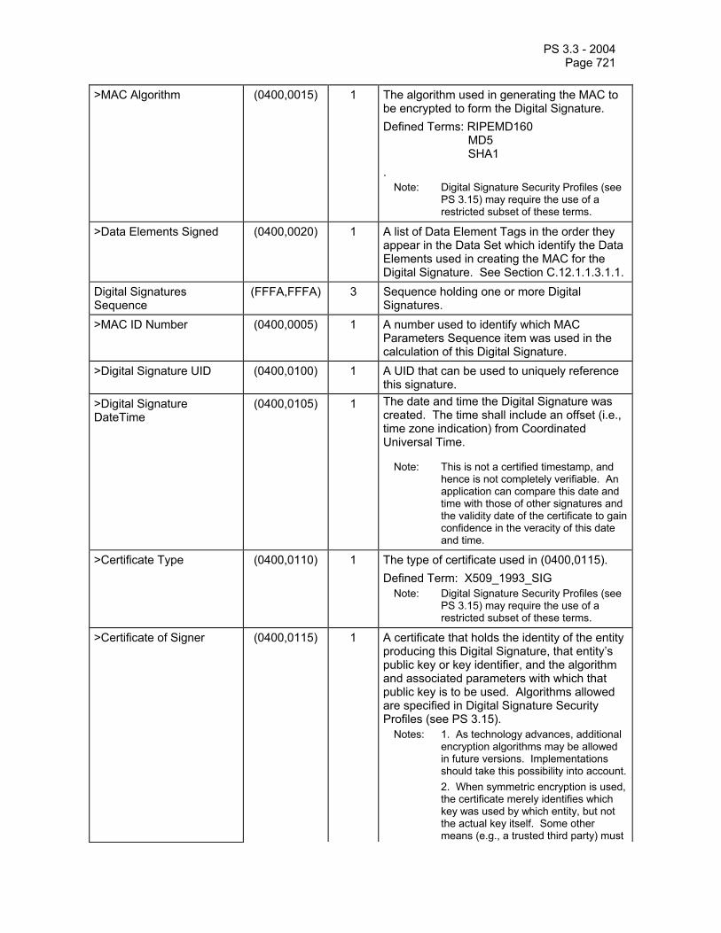
PS 3.3 - 2004 Page 721
>MAC Algorithm (0400,0015) 1 The algorithm used in generating the MAC to be encrypted to form the Digital Signature. Defined Terms: RIPEMD160 MD5 SHA1 .
Note: Digital Signature Security Profiles (see PS 3.15) may require the use of a restricted subset of these terms.
>Data Elements Signed (0400,0020) 1 A list of Data Element Tags in the order they appear in the Data Set which identify the Data Elements used in creating the MAC for the Digital Signature. See Section C.12.1.1.3.1.1.
Digital Signatures Sequence
(FFFA,FFFA) 3 Sequence holding one or more Digital Signatures.
>MAC ID Number (0400,0005) 1 A number used to identify which MAC Parameters Sequence item was used in the calculation of this Digital Signature.
>Digital Signature UID (0400,0100) 1 A UID that can be used to uniquely reference this signature.
>Digital Signature DateTime
(0400,0105) 1 The date and time the Digital Signature was created. The time shall include an offset (i.e., time zone indication) from Coordinated Universal Time.
Note: This is not a certified timestamp, and hence is not completely verifiable. An application can compare this date and time with those of other signatures and the validity date of the certificate to gain confidence in the veracity of this date and time.
>Certificate Type (0400,0110) 1 The type of certificate used in (0400,0115). Defined Term: X509_1993_SIG
Note: Digital Signature Security Profiles (see PS 3.15) may require the use of a restricted subset of these terms.
>Certificate of Signer (0400,0115) 1 A certificate that holds the identity of the entity producing this Digital Signature, that entity’s public key or key identifier, and the algorithm and associated parameters with which that public key is to be used. Algorithms allowed are specified in Digital Signature Security Profiles (see PS 3.15).
Notes: 1. As technology advances, additional encryption algorithms may be allowed in future versions. Implementations should take this possibility into account.
2. When symmetric encryption is used, the certificate merely identifies which key was used by which entity, but not the actual key itself. Some other means (e.g., a trusted third party) must

PS 3.3 - 2004 Page 722
be used to obtain the key.
>Signature (0400,0120) 1 The MAC generated as described in Section 12.2.1.1 and encrypted using the algorithm, parameters, and private key associated with the Certificate of the Signer (0400,0115). See Section C.12.1.1.3.1.2.
>Certified Timestamp Type (0400,0305) 1C The type of certified timestamp used in the Certified Timestamp (0400,0310) Attribute. Required if Certified Timestamp (0400,0310) is present.
Defined Terms: CMS_TSP – Internet X.509 Public Key Infrastructure Time Stamp Protocol
Note: Digital Signature Security Profiles (see PS 3.15) may require the use of a restricted subset of these terms.
>Certified Timestamp (0400,0310) 3 A certified timestamp of the Digital Signature (0400,0120) Attribute Value, which shall be obtained when the Digital Signature is created. See Section C.12.1.1.3.1.3.
C.12.1.1.3.1 Digital Signature Attribute Descriptions C.12.1.1.3.1.1 Data Elements Signed The Data Elements Signed Attribute shall list the Tags of the Data Elements that are included in the MAC calculation. The Tags listed shall reference Data Elements at the same level as the Mac Parameters Sequence (4FFE,0001) Data Element in which the Data Elements Signed Attribute appears. Tags included in Data Elements Signed shall be listed in the order in which they appear within the Data Set.
The following Data Elements shall not be included either implicitly or explicitly in the list of Tags in Data Elements Signed, nor included as part of the MAC calculation:
— The Length to End (0008,0001) or any Tag with an element number of 0000 (i.e., no data set or group lengths may be included in MAC calculations)
— Tags with a group number less than 0008 — Tags associated with Data Elements whose VR is UN — Tags of Data Elements whose VR is SQ, where any Data Element within that Sequence
of Items has a VR of UN recursively — Tags with a group number of FFFA (e.g. the Digital Signatures Sequence) — MAC Parameters Sequence (4FFE,0001) — Data Set Trailing Padding (FFFC,FFFC) — Item Delimitation Item (FFFE,E00D)
Notes: 1. The Length to End and group lengths can change if non-signed Data Elements change, so it
is not appropriate to include them in the MAC calculation. 2. Since the Data Element Tags identifying a sequence and which start each item are included
in the MAC calculation, there is no need to include the Item Delimitation Item Tags. If any of the Data Element Tags in the list refer to a Sequence of Items, then the Tags of all Data Elements within all Items of that Sequence shall be implicitly included in the list of Data Elements Signed, except those disallowed above. This implicit list shall also include the Item Tag

PS 3.3 - 2004 Page 723
(FFFE,E000) Data Elements that separate the Sequence Items and the Sequence Delimitation Item (FFFE,E0DD).
Notes: It is possible to sign individual items within a sequence by including the Digital Signatures Macro in that sequence item. In fact, this is a highly desirable feature, particular when used in the context of reports. The Digital Signatures Macro is applied at the Data Set level, and Sequences of Items are merely Data Sets embedded within a larger Data Set. Essentially, the Digital Signature Macro may be applied recursively.
An example of nesting Digital Signatures within Data Elements is illustrated in the following figure:
Digital Signatures Sequence
MAC Parameters Sequence
MAC Parameters Sequence
Digital Signatures Sequence
Item 1 Attributes
MAC Parameters Sequence
Digital Signatures Sequence
Item 2 Attributes
Pixel Data
Sequence of Items
Other Header Data
Other Header Data
Figure C.12-1 Example of nesting Digital Signatures (Informative)
In this example, there is main signature covering the pixel data and a few other Data Elements, plus two individually signed items within a sequence.

PS 3.3 - 2004 Page 724
For Data Elements with a VR OB (e. g. pixel data) that have an undefined length (i.e. the data is encapsulated as described in PS 3.5), the Item Data Element Tags that separate the fragments shall implicitly be included in the list of Data Elements Signed (i.e. a Data Element with a VR of OB is encoded in the same fashion as a Sequence of Items).
C.12.1.1.3.1.2 Signature To generate the MAC, Data Elements referenced either explicitly or implicitly by the Tags in the Data Elements Signed list shall be encoded using the Transfer Syntax identified by the MAC Calculation Transfer Syntax UID (0400,0010) of the MAC Parameters Sequence item where the Data Elements Signed Attribute appears. Data shall be formed into a byte stream and presented to the MAC Algorithm for computation of the MAC according to the following rules:
For all Data Elements except those with a VR of SQ or with a VR of OB with an undefined length, all Data Element fields, including the Tag, the VR, the reserved field (if any), the Value Length, and the Value, shall be placed into the byte stream in the order encountered.
For Data Elements with a VR of SQ or with a VR of OB with an undefined length, the Tag, the VR, and the reserved field are placed into the byte stream. The Value Length shall not be included. This is followed by each Item Tag in the order encountered, without including the Value Length, followed by the contents of the Value for that item. In the case of an Item within a Data Element whose VR is SQ, these rules are applied recursively to all of the Data Elements within the Value of that Item. After all the Items have been incorporate into the byte stream, a Sequence Delimitation Item Tag (FFFE,E0DD) shall be added to the byte stream presented to the MAC Algorithm, regardless of whether or not it was originally present.
Note: Since the Value Length of Data Elements with a VR of SQ can be either explicit or undefined, the Value Lengths of such Data Elements are left out of the MAC calculation. Similarly, the Value Length of Data Elements with a VR of OB with an undefined length are also left out so that they are handled consistently. If such Data Elements do come with undefined lengths, including the Item Tags that separate the Items or fragments insures that Data Elements cannot be moved between Items or Fragments without compromising the Digital Signature. For those Data Elements with explicit lengths, if the length of an item changes, the added or removed portions would also impact the MAC calculation, so it is not necessary to include explicit lengths in the MAC calculation. It is possible that including the Value Lengths could make cryptoanalysis easier.
After the fields of all the Data Elements in the Data Elements Signed list have been placed into the byte stream presented to the MAC Algorithm according to the above rules, all of the Data Elements within the Digital Signatures Sequence item except the Certificate of Signer (0400,0115), Signature (0400,0120), Certified Timestamp Type (0400,0305), and Certified Timestamp (0400,0310) shall also be encoded according to the above rules, and presented to the MAC algorithm (i.e., the Attributes of the Digital Signature Sequence Item for this particular Digital Signature are also implicitly included in the list of Data Elements Signed, except as noted above).
The resulting MAC code after processing this byte stream by the MAC Algorithm is then encrypted as specified in the Certificate of Signer and placed in the Value of the Signature Data Element.
Notes: 1. The Transfer Syntax used in the MAC calculation may differ from the Transfer Syntax used to exchange the Data Set.
2. Digital Signatures require explicit VR in order to calculate the MAC. An Application Entity which receives a Data Set with an implicit VR Transfer Syntax may not be able to verify Digital Signatures that include Private Data Elements or Data Elements unknown to that Application Entity.This also true of any Data Elements whose VR is UN. Without knowledge of the Value Representation, the receiving Application Entity would be unable to perform proper byte swapping or be able to properly parse sequences in order to generate a MAC.

PS 3.3 - 2004 Page 725
3. If more than one entity signs, each Digital Signature would appear in its own Digital Signatures Sequence item. The Digital Signatures may or may not share the same MAC Parameters Sequence item. 4. The notion of a notary public (i.e., someone who verifies the identity of the signer) for Digital Signatures is partially filled by the authority that issued the Certificate of Signer.
C.12.1.1.3.1.3 Certified Timestamp To generate a certified timestamp, the Value of the Signature (0400,0120) Attribute is sent to a third party, as specified by the protocol referred to by the Certified Timestamp Type (0400,0305) Attribute. The third party then generates and returns a certified timestamp in the form specified by that protocol. The certified timestamp returned by the third party is encoded as a stream of bytes in the Certified Timestamp Attribute.
Note: The timestamp protocol may be specified by a Profile in PS 3.15.
C.12.1.1.4 Encrypted Attribute Descriptions C.12.1.1.4.1 Encrypted Attributes Sequence Each Item of the Encrypted Attributes Sequence (0400,0500) contains an encrypted DICOM dataset containing a single instance of the Encrypted Attributes Data Set (Table C.12-X). It also contains encrypted content-encryption keys for one or more recipients. The encoding is based on the Enveloped-data Content Type of the Cryptographic Message Syntax defined in RFC 2630. It allows to encrypt the embedded Data Set for an arbitrary number of recipients using any of the three key management techniques supported by RFC 2630:
• Key Transport: the content-encryption key is encrypted in the recipient's public key;
• Key Agreement: the recipient's public key and the sender's private key are used to generate a pairwise symmetric key, then the content-encryption key is encrypted in the pairwise symmetric key; and
• Symmetric key-encryption Keys: the content-encryption key is encrypted in a previously distributed symmetric key-encryption key.
A recipient decodes the embedded Encrypted Attributes Data Set by decrypting one of the encrypted content-encryption keys, decrypting the encrypted dataset with the recovered content-encryption key, and then decoding the DICOM dataset using the Transfer Syntax specified in Encrypted Content Transfer Syntax UID (0400,0510).
Multiple Items may be present in the Encrypted Attributes Sequence. The different Items may contain Encrypted Attributes Data Sets with the same or different sets of Attributes and may contain encrypted content-encryption keys for the same or different sets of recipients. However, if the same Attribute is contained in more than one embedded Encrypted Attributes Data Set, the value of the Attribute must be identical in all embedded Encrypted Attributes Data Sets in which the Attribute is contained.
Note: If the Encrypted Attributes Sequence contains more than one Item, and a recipient holds the key for more than one of the items, the recipient may either decode any single one or more of the embedded Data Sets at its own discretion. Since the same Attribute is required to have the same value in all embedded Encrypted Attributes Data Sets, it is safe to “overlay” multiple embedded Encrypted Attributes Data Sets in an arbitrary order upon decoding.
C.12.1.1.4.2 Encrypted Content The Encrypted Content (0400,0520) Attribute contains an Enveloped-data content type of the cryptographic message syntax defined in RFC 2630. The encrypted content of the Enveloped-data content type is an instance of the Encrypted Attributes Data Set as shown in Table C.12-6

PS 3.3 - 2004 Page 726
(i.e., it is a Sequence with a single Item), encoded with the Transfer Syntax specified by the Encrypted Content Transfer Syntax UID (0400,0510) Attribute. Figure C.12-2 shows an example of how the Encrypted Content is encoded. The exact use of this Data Set is defined in the Attribute Confidentiality Profiles in PS 3.15.
Since the de-identified SOP Instance is a significantly altered version of the original Data Set, it is a new SOP Instance, with a SOP Instance UID that differs from the original Data Set.
Note: 1. Content encryption may require that the content (the DICOM Data Set) be padded to a multiple of some block size. This shall be performed according to the Content-encryption Process defined in RFC-2630.
2. Any standard or private Transfer Syntax may be specified in Encrypted Content Transfer Syntax UID (0400,0510) unless encoding is performed in accordance with an Attribute Confidentiality Profile that specifies additional restrictions. In general, an application entity decoding the Encrypted Attributes Sequence may not assume any particular Transfer Syntax or set of Transfer Syntaxes to be used with Encrypted Content Transfer Syntax UID (0400,0510).
3. For certain applications it might be necessary to “blacken” (remove) identifying information that is burned in to the image pixel data. The Encrypted Attributes Data Set does not specify a means of restoring the original image information without the complete image pixel data being encoded inside the Modified Attributes Sequence (0400,0550). If access to the original, unmodified pixel data is required and the image pixel data cannot be replicated inside the Modified Attributes Sequence (0400,0550) due to resource considerations, the SOP Instance UID may be used to locate the original SOP Instance from which the de-identified version was derived.
4. There is no guarantee that the original SOP Instance can be reconstructed from the data in Encrypted Content. If access to the original data is required, the (de-encrypted) UIDs may be used to locate the original SOP Instance from which the de-identified version was derived.
Table C.12-6
ENCRYPTED ATTRIBUTES DATA SET ATTRIBUTES Attribute Name Tag Type Attribute Description Modified Attributes Sequence (0400,0550) 1 Sequence of Items containing all Attributes
that were removed or replaced by “dummy values” in the main dataset during de-identification of the SOP instance. Upon reversal of the de-identification process, the Attributes are copied back into the main dataset, replacing any dummy values that might have been created. Only a single Item shall be present.
> Any Attribute from the main dataset that was modified or removed during the de-identification process.
3

PS 3.3 - 2004 Page 727
Attributes to be encrypted
Item 1 (of only 1)
Modified Attributes Sequence
Cryptographic MessageSyntax envelopeCMS attributes
Encrypted Content Transfer SyntaxEncrypted Content
Encrypted Content
Item 1 (of n)
Encrypted Content Transfer SyntaxEncrypted Content
Item 2 (of n)
CMS envelope
Encrypted Content Transfer SyntaxEncrypted Content
Item n (of n)
CMS envelope
Encrypted Attributes Sequence
Attributes (unencrypted)
SOP Instance
Figure C.12-2 Example encoding of Encrypted Attributes Data Set (Informative)
C.12.1.1.5 Contributing Equipment Sequence Contributing Equipment Sequence (0018,A001) allows equipment to be described which has contributed towards the creation of the composite instance. The general class of contribution is denoted via a coded entry within the Purpose of Reference Code Sequence (0040,A170).
Notes: 1. For example, a post-processing application creating DERIVED images from ORIGINAL images would place its own identification within the Equipment Module and identify the original acquisition equipment as an Item within the Contributing Equipment Sequence (0018,A001). Here, the value of the Purpose of Reference Code Sequence (0040,A170) within the Item would

PS 3.3 - 2004 Page 728
be (109101, DCM, ”Acquisition Equipment"). Image display applications wishing to annotate images with information related to the acquisition environment would prefer to extract such details from the Contributing Equipment Sequence rather than the Equipment Module.
2. For example, an image fusion application would place its own identification within the Equipment Module and identify each of the original acquisition equipment as separate Items within the Contributing Equipment Sequence (0018,A001). Here, the value of the Purpose of Reference Code Sequence (0040,A170) within each Item would be (109101, DCM, ”Acquisition Equipment").
3. For example, a post-processing application creating DERIVED images from other DERIVED images would place its own identification within the Equipment Module and add the source equipment as an additional Item within the Contributing Equipment Sequence (0018,A001). Here, the value of the Purpose of Reference Code Sequence (0040,A170) within the Item would be (109102, DCM, ”Processing Equipment").
4. For example, a gateway device that coerces attributes of existing composite instances (without creating new composite instances) would retain information about the creating equipment within the Equipment Module and provide its own identification as an Item within the Contributing Equipment Sequence (0018,A001). Here, the value of the Purpose of Reference Code Sequence (0040,A170) within the Item would be (109103, DCM, ”Modifying Equipment").
C.12.2 Common Instance Reference Module Table C.12-7 defines the Attributes that describe the hierarchical relationships of any SOP Instances referenced from other Modules within the Instance in which this Module occurs.
Table C.12-7 COMMON INSTANCE REFERENCE MODULE ATTRIBUTES
Attribute Name Tag Type Attribute Description Include Series and Instance Reference Macro, Table 10-4. Identifies all Series within the Study of
which this Instance is a part, which Series contain Instances that are referenced elsewhere in this Instance.
Studies Containing Other Referenced Instances Sequence
(0008,1200) 1C Sequence of items each identifying a Study other than the Study of which this Instance is a part, which Studies contain Instances that are referenced elsewhere in this Instance. One or more Items shall be present. Required if this Instance references Instances in other Studies.
>Study Instance UID (0020,000D) 1 Unique identifier of the Study containing the referenced Instances.
>Include Series and Instance Reference Macro, Table 10-4.

PS 3.3 - 2004 Page 729
C.13 PRINT MANAGEMENT SPECIFIC MODULES
The following Sections specify Modules used for Print Management.
C.13.1 Basic Film Session Presentation Module Table C.13-1
BASIC FILM SESSION PRESENTATION MODULE ATTRIBUTES Attribute name Tag Attribute Description Number of Copies (2000,0010) Number of copies to be printed for each film of the
film session. Print Priority (2000,0020) Specifies the priority of the print job.
Enumerated Values: HIGH MED LOW
Medium Type (2000,0030) Type of medium on which the print job will be printed. Defined Terms: PAPER CLEAR FILM BLUE FILM MAMMO CLEAR FILM MAMMO BLUE FILM
Film Destination (2000,0040) Film destination. Defined Terms: MAGAZINE = the exposed film is stored in
film magazine PROCESSOR = the exposed film is
developed in film processor BIN_i = the exposed film is deposited in a
sorter bin where “I” represents the bin number. Film sorter BINs shall be numbered sequentially starting from one and no maxiumu is placed on the number of BINs. The encoding of the BIN number shall not contain leading zeros.
Film Session Label (2000,0050) Human readable label that identifies the film sessionMemory Allocation (2000,0060) Amount of memory allocated for the film session.
Value is expressed in KB Owner ID (2100,0160) Identification of the owner of the film session
C.13.2 Basic Film Session Relationship Module Table C.13-2
BASIC FILM SESSION RELATIONSHIP MODULE ATTRIBUTES Attribute Name Tag Attribute Description Referenced Film Box Sequence (2000,0500) A Sequence which provides references to a set of
Film Box SOP Class/Instance pairs. Zero or more Items may be included in this Sequence.
>Referenced SOP Class UID (0008,1150) Uniquely identifies the referenced SOP Class.

PS 3.3 - 2004 Page 730
>Referenced SOP Instance UID (0008,1155) Uniquely identifies the referenced SOP Instance. Proposed Study Sequence (2130,00A0) Attributes that may be used to identify Stored Print
Storage and Hardcopy Image SOP Instances created to store this Film Session.
>Patient's Name (0010,0010) See C.2.2 for description. >Patient ID (0010,0020) See C.2.2 for description. >Patient's Birth Date (0010,0030) See C.2.3 for description. >Patient's Sex (0010,0040) See C.2.3 for description. >Patient's Birth Time (0010,0032) See C.2.3 for description. >Other Patient ID (0010,1000) See C.2.2 for description. >Other Patient Names (0010,1001) See C.2.2 for description. >Ethnic Group (0010,2160) See C.2.3 for description. >Patient Comments (0010,4000) See C.2.3 for description. >Study Instance UID (0020,000D) See C.4.1 for description. >Study Date (0008,0020) See C.4.5 for description. >Study Time (0008,0030) See C.4.5 for description. >Referring Physician's Name (0008,0090) See C.3.4 for description. >Study ID (0020,0010) See C.4.2 for description. >Accession Number (0008,0050) See C.4.1 for description. >Study Description (0008,1030) See C.4.9 for description. >Name of Physician(s) Reading Study (0008,1060) See C.7.2.1 for description. >Admitting Diagnoses Description (0008,1080) See C.7.2.2 for description. >Patient's Age (0010,1010) See C.2.3 for description. >Patient's Size (0010,1020) See C.2.3 for description. >Patient's Weight (0010,1030) See C.2.3 for description. >Occupation (0010,2180) See C.2.3 for description. >Additional Patient’s History (0010,21B0) See C.2.4 for description. >Series Number (0020,0011) See C.7.3.1 for description

PS 3.3 - 2004 Page 731
C.13.3 Basic Film Box Presentation Module Table C.13-3
BASIC FILM BOX PRESENTATION MODULE ATTRIBUTES Attribute Name Tag Attribute Description Image Display Format (2010,0010) Type of image display format. Enumerated Values:
STANDARD\C,R : film contains equal size rectangular image boxes with R rows of image boxes and C columns of image boxes; C and R are integers. ROW\R1,R2,R3, etc. : film contains rows with equal size rectangular image boxes with R1 image boxes in the first row, R2 image boxes in second row, R3 image boxes in third row, etc.; R1, R2, R3, etc. are integers. COL\C1,C2,C3, etc.: film contains columns with equal size rectangular image boxes with C1 image boxes in the first column, C2 image boxes in second column, C3 image boxes in third column, etc.; C1, C2, C3, etc. are integers. SLIDE : film contains 35mm slides; the number of slides for a particular film size is configuration dependent. SUPERSLIDE : film contains 40mm slides; the number of slides for a particular film size is configuration dependent. CUSTOM\i : film contains a customized ordering of rectangular image boxes; i identifies the image display format; the definition of the image display formats is defined in the Conformance Statement; i is an integer
Annotation Display Format ID (2010,0030) Identification of annotation display format. The definition of the annotation display formats and the annotation box position sequence are defined in the Conformance Statement
Film Orientation (2010,0040) Film orientation. Enumerated Values: PORTRAIT = vertical film position LANDSCAPE = horizontal film position
Film Size ID (2010,0050) Film size identification. Defined Terms: 8INX10IN 8_5INX11IN 10INX12IN 10INX14IN 11INX14IN 11INX17IN 14INX14IN 14INX17IN 24CMX24CM 24CMX30CM A4 A3
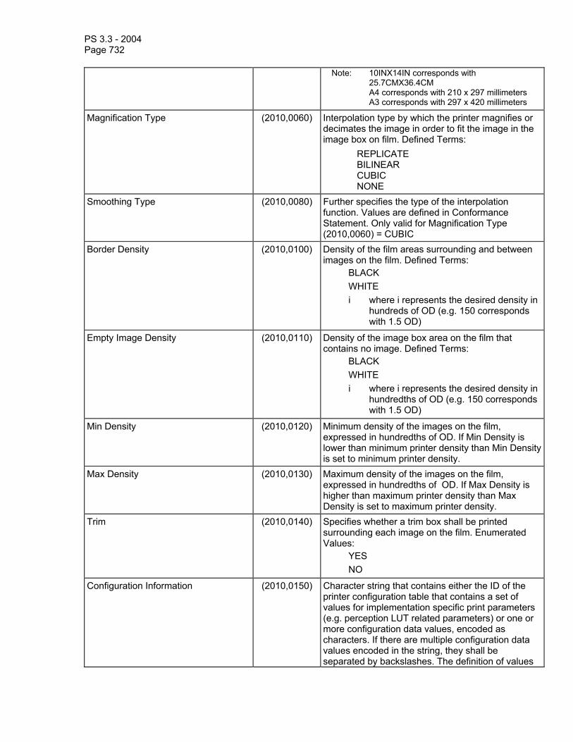
PS 3.3 - 2004 Page 732
Note: 10INX14IN corresponds with 25.7CMX36.4CM A4 corresponds with 210 x 297 millimeters A3 corresponds with 297 x 420 millimeters
Magnification Type (2010,0060) Interpolation type by which the printer magnifies or decimates the image in order to fit the image in the image box on film. Defined Terms: REPLICATE BILINEAR CUBIC NONE
Smoothing Type (2010,0080) Further specifies the type of the interpolation function. Values are defined in Conformance Statement. Only valid for Magnification Type (2010,0060) = CUBIC
Border Density (2010,0100) Density of the film areas surrounding and between images on the film. Defined Terms:
BLACK WHITE i where i represents the desired density in
hundreds of OD (e.g. 150 corresponds with 1.5 OD)
Empty Image Density (2010,0110) Density of the image box area on the film that contains no image. Defined Terms:
BLACK WHITE i where i represents the desired density in
hundredths of OD (e.g. 150 corresponds with 1.5 OD)
Min Density (2010,0120) Minimum density of the images on the film, expressed in hundredths of OD. If Min Density is lower than minimum printer density than Min Density is set to minimum printer density.
Max Density (2010,0130) Maximum density of the images on the film, expressed in hundredths of OD. If Max Density is higher than maximum printer density than Max Density is set to maximum printer density.
Trim (2010,0140) Specifies whether a trim box shall be printed surrounding each image on the film. Enumerated Values:
YES NO
Configuration Information (2010,0150) Character string that contains either the ID of the printer configuration table that contains a set of values for implementation specific print parameters (e.g. perception LUT related parameters) or one or more configuration data values, encoded as characters. If there are multiple configuration data values encoded in the string, they shall be separated by backslashes. The definition of values

PS 3.3 - 2004 Page 733
shall be contained in the SCP's Conformance Statement. Defined Terms: CS000-CS999: Implementation specific curve type.
Note: It is recommended that for SCPs, CS000 represent the lowest contrast and CS999 the highest contrast levels available.
Illumination (2010,015E) Luminance of lightbox illuminating a piece of transmissive film, or for the case of reflective media, luminance obtainable from diffuse reflection of the illumination present. Expressed as L0, in candelas per square meter (cd/m2).
Reflected Ambient Light (2010,0160) For transmissive film, luminance contribution due to reflected ambient light. Expressed as La, in candelas per square meter (cd/m2).
Requested Resolution ID (2020,0050) Specifies the resolution at which images in this Film Box are to be printed. Defined Terms:
STANDARD = approximately 4k x 5k printable pixels on a 14 x 17 inch film
HIGH = Approximately twice the resolution of STANDARD.

PS 3.3 - 2004 Page 734
C.13.3.1 Image display format C.13.3.1.1 Standard image display format The standard format subdivides a film into image boxes of equal size. Therefore, the film layout is fully symmetrical, i.e. the arrangement of image boxes on film is left-right and top-bottom symmetric.
Example : STANDARD\3,4
vertical symmetry line
Symmetry line horizontal

PS 3.3 - 2004 Page 735
C.13.3.1.2 Row symmetric image display format The row symmetric image display format subdivides a film into rows of image boxes of equal size. As a result, the layout is left-right symmetric, the associated symmetry line is vertical (V). There is no top-bottom symmetry.
Example : ROW\2,3
verticalsymmetry line
2 images of equal size in a row
3 images of equal size in a row

PS 3.3 - 2004 Page 736
C.13.3.1.3 Column symmetric image display format The column symmetric image display format subdivides a film into columns of image boxes of equal size. As a result, the layout is top-button symmetric, the associated symmetry line is horizontal (H). There is no left-right symmetry.
Example : COL\1,4
1 image in a column
4 images of equal size in a column
horizontal symmetry line
C.13.4 Basic Film Box Relationship Module Table C.13-4
BASIC FILM BOX RELATIONSHIP MODULE ATTRIBUTES Attribute Name Tag Attribute Description Referenced Film Session Sequence (2010,0500) A sequence which provides references to a Film
Session SOP Class/Instance pairs. Only a single Item shall be permitted in this Sequence.
>Referenced SOP Class UID (0008,1150) Uniquely identifies the referenced SOP Class. >Referenced SOP Instance UID (0008,1155) Uniquely identifies the referenced SOP Instance. Referenced Image Box Sequence (2010,0510) A sequence which provides references to a set of
Image Box SOP Class/Instance pairs. One or more Items may be included in this Sequence.
>Referenced SOP Class UID (0008,1150) Uniquely identifies the referenced SOP Class. >Referenced SOP Instance UID (0008,1155) Uniquely identifies the referenced SOP Instance. Referenced Basic Annotation Box Sequence
(2010,0520) A Sequence which provides references to a set of Basic Annotation Box SOP Class/Instance pairs. Zero or more Items may be included in this Sequence.
>Referenced SOP Class UID (0008,1150) Uniquely identifies the referenced SOP Class. >Referenced SOP Instance UID (0008,1155) Uniquely identifies the referenced SOP Instance. Referenced Presentation LUT (2050,0500) A sequence which provides references to a
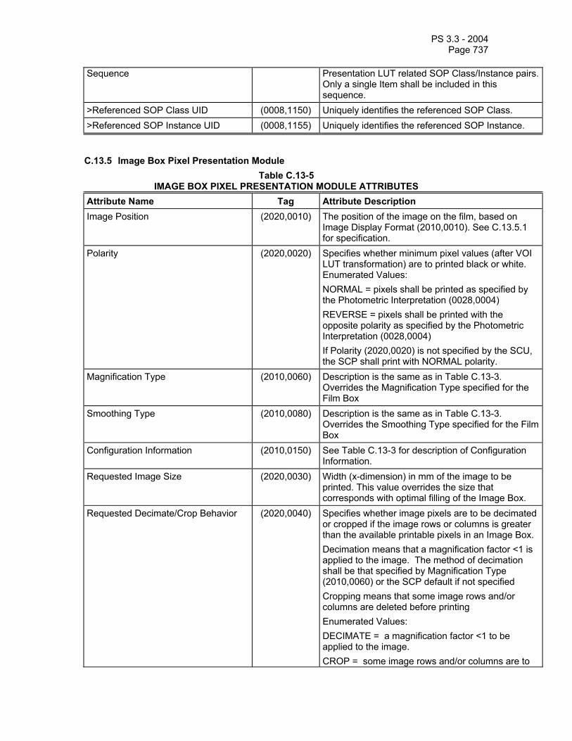
PS 3.3 - 2004 Page 737
Sequence Presentation LUT related SOP Class/Instance pairs. Only a single Item shall be included in this sequence.
>Referenced SOP Class UID (0008,1150) Uniquely identifies the referenced SOP Class. >Referenced SOP Instance UID (0008,1155) Uniquely identifies the referenced SOP Instance.
C.13.5 Image Box Pixel Presentation Module Table C.13-5
IMAGE BOX PIXEL PRESENTATION MODULE ATTRIBUTES Attribute Name Tag Attribute Description Image Position (2020,0010) The position of the image on the film, based on
Image Display Format (2010,0010). See C.13.5.1 for specification.
Polarity (2020,0020) Specifies whether minimum pixel values (after VOI LUT transformation) are to printed black or white. Enumerated Values: NORMAL = pixels shall be printed as specified by the Photometric Interpretation (0028,0004) REVERSE = pixels shall be printed with the opposite polarity as specified by the Photometric Interpretation (0028,0004) If Polarity (2020,0020) is not specified by the SCU, the SCP shall print with NORMAL polarity.
Magnification Type (2010,0060) Description is the same as in Table C.13-3. Overrides the Magnification Type specified for the Film Box
Smoothing Type (2010,0080) Description is the same as in Table C.13-3. Overrides the Smoothing Type specified for the Film Box
Configuration Information (2010,0150) See Table C.13-3 for description of Configuration Information.
Requested Image Size (2020,0030) Width (x-dimension) in mm of the image to be printed. This value overrides the size that corresponds with optimal filling of the Image Box.
Requested Decimate/Crop Behavior (2020,0040) Specifies whether image pixels are to be decimated or cropped if the image rows or columns is greater than the available printable pixels in an Image Box. Decimation means that a magnification factor <1 is applied to the image. The method of decimation shall be that specified by Magnification Type (2010,0060) or the SCP default if not specified Cropping means that some image rows and/or columns are deleted before printing Enumerated Values: DECIMATE = a magnification factor <1 to be applied to the image. CROP = some image rows and/or columns are to

PS 3.3 - 2004 Page 738
be deleted before printing. The specific algorithm for cropping shall be described in the SCP Conformance Statement. FAIL = the SCP shall not crop or decimate
Basic Grayscale Image Sequence (2020,0110) A sequence which provides the content of the grayscale image pixel data to be printed. This is a specialization of the Image Pixel Module defined in C.7.6.3 of this part. It is encoded as a sequence of Attributes of the Image Pixel Module. Zero or one Item may be included in this Sequence. See PS 3.4 for further description.
>Samples Per Pixel (0028,0002) See C.7.6.3 for description of Image Pixel Module. Enumerated Value: 1
>Photometric Interpretation (0028,0004) See C.7.6.3 for description of Image Pixel Module. Enumerated Values: MONOCHROME1 MONOCHROME2
>Rows (0028,0010) See C.7.6.3 for description of Image Pixel Module >Columns (0028,0011) See C.7.6.3 for description of Image Pixel Module >Pixel Aspect Ratio (0028,0034) See C.7.6.3 for description of Image Pixel Module >Bits Allocated (0028,0100) See C.7.6.3 for description of Image Pixel Module.
Enumerated Values: 8 (if Bits Stored = 8) 16 (if Bits Stored = 12)
>Bits Stored (0028,0101) See C.7.6.3 for description of Image Pixel Module. Enumerated Values: 8 12
>High Bit (0028,0102) See C.7.6.3 for description of Image Pixel Module. Enumerated Values: 7 (if BITS STORED = 8) 11 (if BITS STORED = 12)
>Pixel Representation (0028,0103) See C.7.6.3 for description of Image Pixel Module. Enumerated Value: 0 (unsigned integer)
>Pixel Data (7FE0,0010) See C.7.6.3 for description of Image Pixel Module Basic Color Image Sequence (2020,0111) A sequence which provides the content of the color
image pixel data to be printed. It is a specialization of the Image Pixel Module defined in C.7.6.3 of this part. It is encoded as a sequence of Attributes of the Image Pixel Module. Zero or one Item may be included in this Sequence. See PS 3.4 for further description.
>Samples Per Pixel (0028,0002) See C.7.6.3 for description of Image Pixel Module. Enumerated Value: 3

PS 3.3 - 2004 Page 739
>Photometric Interpretation (0028,0004) See C.7.6.3 for description of Image Pixel Module. Enumerated Value: RGB
>Planar Configuration (0028,0006) See C.7.6.3 for description of Image Pixel Module. Enumerated Value: 1 (frame interleave)
>Rows (0028,0010) See C.7.6.3 for description of Image Pixel Module. >Columns (0028,0011) See C.7.6.3 for description of Image Pixel Module. >Pixel Aspect Ratio (0028,0034) See C.7.6.3 for description of Image Pixel Module. >Bits Allocated (0028,0100) See C.7.6.3 for description of Image Pixel Module.
Enumerated Value: 8 >Bits Stored (0028,0101) See C.7.6.3 for description of Image Pixel Module.
Enumerated Value: 8
>High Bit (0028,0102) See C.7.6.3 for description of Image Pixel Module. Enumerated Value: 7
>Pixel Representation (0028,0103) See C.7.6.3 for description of Image Pixel Module. Enumerated Value: 0000H (unsigned integer)
>Pixel Data (7FE0,0010) See C.7.6.3 for description of Image Pixel Module Referenced Image Overlay Box Sequence
(2020,0130) A sequence which provides references to an Image Overlay Box SOP Class/Instance pair and a specific frame number in multi-frame instances. Zero or one Item may be included in this Sequence.
>Referenced SOP Class UID (0008,1150) Uniquely identifies the referenced SOP Class. >Referenced SOP Instance UID (0008,1155) Uniquely identifies the referenced SOP Instance. Original Image Sequence (2130,00C0) Attributes of the original modality images to be
printed in this Film Session. >Study Instance UID (0020,000D) See C.7.2.1 for description. >Series Instance UID (0020,000E) See C.7.3.1 for description. >Patient ID (0010,0020) See C.7.1.1 for description. >Referenced SOP Class UID (0008,1150) SOP Class UID of the original modality image used
to create this Image Box. >Referenced SOP Instance UID (0008,1155) SOP Instance UID of the original modality image
used to create this Image Box. >Referenced Frame Number (0008,1160) See C.7.6.1 for description. >Instance Number (0020,0013) See C.7.6.1 for description.
C.13.5.1 Image Position The position of the image on the film; the encoding of the image position sequence is based on the selected Image Display Format (2010,0010). The image position sequence shall be increasing order beginning with the value 1. Image Position (2020,0010) is defined as follows:

PS 3.3 - 2004 Page 740
- STANDARD display format: image box sequence shall be major row order (from left-to-right and from top-to-bottom); top left image position shall be equal to 1.
- ROW display format: image box sequence shall be major row order (from left-to-right and from top-to-bottom); top left image position shall be set to 1.
- COL display format: image box sequence shall be major column order (from top-to-bottom and from left-to-right); top left image position shall be equal to 1.
- SLIDE display format: image box sequence shall be major row order (from left-to-right and from top-to-bottom); top left image position shall be set to 1.
- SUPERSLIDE display format: image box sequence shall be major row order (from left-to-right and from top-to-bottom); top left image position shall be set to 1.
- CUSTOM STANDARD display format: image box sequence shall be defined in the Conformance Statement; top left image position shall be set to 1.
C.13.6 Image Box Relationship Module (Retired) This section was previously defined in DICOM. It is now retired. See PS 3.3-1998.
C.13.7 Basic Annotation Presentation Module Table C.13-7
BASIC ANNOTATION PRESENTATION MODULE ATTRIBUTES Attribute Name Tag Attribute Description Annotation Position (2030,0010) The position of the annotation box in the parent film
box. Annotation position sequence depends on the selected Annotation Display Format ID (2010,0030)
Text String (2030,0020) Text string
C.13.8 Print Job Module Table C.13-8
PRINT JOB MODULE ATTRIBUTES Attribute Name Tag Attribute Description Execution Status (2100,0020) Execution status of print job. Enumerated Values:
PENDING PRINTING DONE FAILURE
Execution Status Info (2100,0030) Additional information about Execution Status (2100,0020). Defined Terms when the Execution Status is DONE or PRINTING:
NORMAL Defined Terms when the Execution Status is FAILURE: INVALID PAGE DES = The specified page
layout cannot be printed or other page description errors have been detected.
INSUFFIC MEMORY = There is not enough memory available to complete this job.
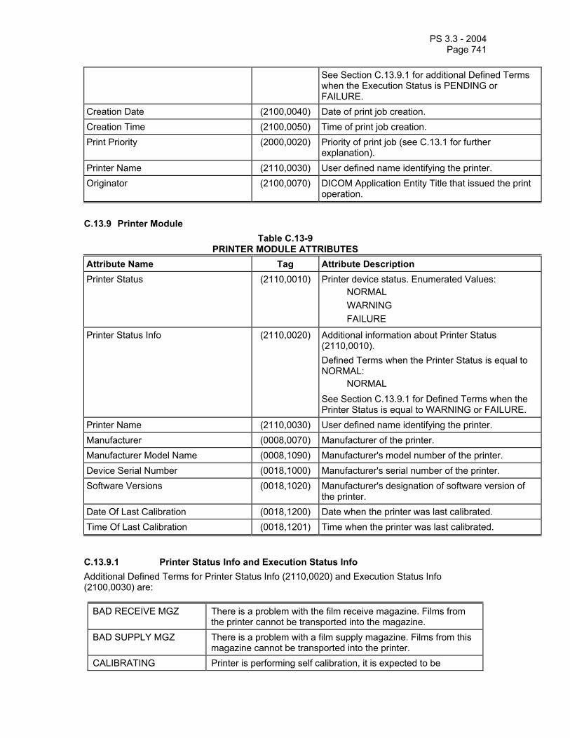
PS 3.3 - 2004 Page 741
See Section C.13.9.1 for additional Defined Terms when the Execution Status is PENDING or FAILURE.
Creation Date (2100,0040) Date of print job creation. Creation Time (2100,0050) Time of print job creation. Print Priority (2000,0020) Priority of print job (see C.13.1 for further
explanation). Printer Name (2110,0030) User defined name identifying the printer. Originator (2100,0070) DICOM Application Entity Title that issued the print
operation. C.13.9 Printer Module
Table C.13-9 PRINTER MODULE ATTRIBUTES
Attribute Name Tag Attribute Description Printer Status (2110,0010) Printer device status. Enumerated Values:
NORMAL WARNING FAILURE
Printer Status Info (2110,0020) Additional information about Printer Status (2110,0010). Defined Terms when the Printer Status is equal to NORMAL:
NORMAL See Section C.13.9.1 for Defined Terms when the Printer Status is equal to WARNING or FAILURE.
Printer Name (2110,0030) User defined name identifying the printer. Manufacturer (0008,0070) Manufacturer of the printer. Manufacturer Model Name (0008,1090) Manufacturer's model number of the printer. Device Serial Number (0018,1000) Manufacturer's serial number of the printer. Software Versions (0018,1020) Manufacturer's designation of software version of
the printer. Date Of Last Calibration (0018,1200) Date when the printer was last calibrated. Time Of Last Calibration (0018,1201) Time when the printer was last calibrated.
C.13.9.1 Printer Status Info and Execution Status Info Additional Defined Terms for Printer Status Info (2110,0020) and Execution Status Info (2100,0030) are:
BAD RECEIVE MGZ There is a problem with the film receive magazine. Films from the printer cannot be transported into the magazine.
BAD SUPPLY MGZ There is a problem with a film supply magazine. Films from this magazine cannot be transported into the printer.
CALIBRATING Printer is performing self calibration, it is expected to be

PS 3.3 - 2004 Page 742
available for normal operation shortly. CALIBRATION ERR An error in the printer calibration has been detected, quality of
processed films may not be optimal. CHECK CHEMISTRY A problem with the processor chemicals has been detected,
quality of processed films may not be optimal. CHECK SORTER There is an error in the film sorter. CHEMICALS EMPTY There are no processing chemicals in the processor, films will
not be printed and processed until the processor is back to normal.
CHEMICALS LOW The chemical level in the processor is low, if not corrected, it will probably shut down soon.
COVER OPEN One or more printer or processor covers, drawers, doors are open.
ELEC CONFIG ERR Printer configured improperly for this job. ELEC DOWN Printer is not operating due to some unspecified electrical
hardware problem. ELEC SW ERROR Printer not operating for some unspecified software error. EMPTY 8X10 The 8x10 inch film supply magazine is empty. EMPTY 8X10 BLUE The 8x10 inch blue film supply magazine is empty. EMPTY 8X10 CLR The 8x10 inch clear film supply magazine is empty. EMPTY 8X10 PAPR The 8x10 inch paper supply magazine is empty. EMPTY 10X12 The 10x12 inch film supply magazine is empty. EMPTY 10X12 BLUE The 10x12 inch blue film supply magazine is empty. EMPTY 10X12 CLR The 10x12 inch clear film supply magazine is empty. EMPTY 10X12 PAPR The 10x12 inch paper supply magazine is empty. EMPTY 10X14 The 10x14 inch film supply magazine is empty. EMPTY 10X14 BLUE The 10x14 inch blue film supply magazine is empty. EMPTY 10X14 CLR The 10x14 inch clear film supply magazine is empty. EMPTY 10X14 PAPR The 10x14 inch paper supply magazine is empty. EMPTY 11X14 The 11x14 inch film supply magazine is empty. EMPTY 11X14 BLUE The 11x14 inch blue film supply magazine is empty. EMPTY 11X14 CLR The 11x14 inch clear film supply magazine is empty. EMPTY 11X14 PAPR The 11x14 inch paper supply magazine is empty. EMPTY 14X14 The 14x14 inch film supply magazine is empty. EMPTY 14X14 BLUE The 14x14 inch blue film supply magazine is empty. EMPTY 14X14 CLR The 14x14 inch clear film supply magazine is empty. EMPTY 14X14 PAPR The 14x14 inch paper supply magazine is empty. EMPTY 14X17 The 14x17 inch film supply magazine is empty. EMPTY 14X17 BLUE The 14x17 inch blue film supply magazine is empty. EMPTY 14X17 CLR The 14x17 inch clear film supply magazine is empty. EMPTY 14X17 PAPR The 14x17 inch paper supply magazine is empty.

PS 3.3 - 2004 Page 743
EMPTY 24X24 The 24x24 cm film supply magazine is empty. EMPTY 24X24 BLUE The 24x24 cm blue film supply magazine is empty. EMPTY 24X24 CLR The 24x24 cm clear film supply magazine is empty. EMPTY 24X24 PAPR The 24x24 cm paper supply magazine is empty. EMPTY 24X30 The 24x30 cm film supply magazine is empty. EMPTY 24X30 BLUE The 24x30 cm blue film supply magazine is empty. EMPTY 24X30 CLR The 24x30 cm clear film supply magazine is empty. EMPTY 24X30 PAPR The 24x30 cm paper supply magazine is empty. EMPTY A4 PAPR The A4 paper supply magazine is empty. EMPTY A4 TRANS The A4 transparency supply magazine is empty. EXPOSURE FAILURE The exposure device has failed due to some unspecified
reason. FILM JAM A film transport error has occurred and a film is jammed in the
printer or processor. FILM TRANSP ERR There is a malfunction with the film transport, there may or may
not be a film jam. FINISHER EMPTY The finisher is empty. FINISHER ERROR The finisher is not operating due to some unspecified reason. FINISHER LOW The finisher is low on supplies LOW 8X10 The 8x10 inch film supply magazine is low. LOW 8X10 BLUE The 8x10 inch blue film supply magazine is low. LOW 8X10 CLR The 8x10 inch clear film supply magazine is low. LOW 8X10 PAPR The 8x10 inch paper supply magazine is low. LOW 10X12 The 10x12 inch film supply magazine is low. LOW 10X12 BLUE The 10x12 inch blue film supply magazine is low. LOW 10X12 CLR The 10x12 inch clear film supply magazine is low. LOW 10X12 PAPR The 10x12 inch paper supply magazine is low. LOW 10X14 The 10x14 inch film supply magazine is low. LOW 10X14 BLUE The 10x14 inch blue film supply magazine is low. LOW 10X14 CLR The 10x14 inch clear film supply magazine is low. LOW 10X14 PAPR The 10x14 inch paper supply magazine is low. LOW 11X14 The 11x14 inch film supply magazine is low. LOW 11X14 BLUE The 11x14 inch blue film supply magazine is low. LOW 11X14 CLR The 11x14 inch clear film supply magazine is low. LOW 11X14 PAPR The 11x14 inch paper supply magazine is low. LOW 14X14 The 14x14 inch film supply magazine is low. LOW 14X14 BLUE The 14x14 inch blue film supply magazine is low. LOW 14X14 CLR The 14x14 inch clear film supply magazine is low. LOW 14X14 PAPR The 14x14 inch paper supply magazine is low. LOW 14X17 The 14x17 inch film supply magazine is low.

PS 3.3 - 2004 Page 744
LOW 14X17 BLUE The 14x17 inch blue film supply magazine is low. LOW 14X17 CLR The 14x17 inch clear film supply magazine is low. LOW 14X17 PAPR The 14x17 inch paper supply magazine is low. LOW 24X24 The 24x24 cm film supply magazine is low. LOW 24X24 BLUE The 24x24 cm blue film supply magazine is low. LOW 24X24 CLR The 24x24 cm clear film supply magazine is low. LOW 24X24 PAPR The 24x24 cm paper supply magazine is low. LOW 24X30 The 24x30 cm film supply magazine is low. LOW 24X30 BLUE The 24x30 cm blue film supply magazine is low. LOW 24X30 CLR The 24x30 cm clear film supply magazine is low. LOW 24X30 PAPR The 24x30 cm paper supply magazine is low. LOW A4 PAPR The A4 paper supply magazine is low. LOW A4 TRANS The A4 transparency supply magazine is low. NO RECEIVE MGZ The film receive magazine not available NO RIBBON The ribbon cartridge needs to be replaced. NO SUPPLY MGZ The film supply magazine specified for this job is not available. CHECK PRINTER The printer is not ready at this time, operator intervention is
required to make the printer available. CHECK PROC The processor is not ready at this time, operator intervention is
required to make the printer available. PRINTER DOWN The printer is not operating due to some unspecified reason. PRINTER BUSY Printer is not available at this time, but should become ready
without user intervention. This is to handle non-initialization instances.
PRINT BUFF FULL The Printer ‘s buffer capacity is full. The printer is unable to accept new images in this state. The printer will correct this without user intervention. The SCU should retry later.
PRINTER INIT The printer is not ready at this time, it is expected to become available without intervention. For example, it may be in a normal warm-up state.
PRINTER OFFLINE The printer has been disabled by an operator or service person. PROC DOWN The processor is not operating due to some unspecified reason. PROC INIT The processor is not ready at this time, it is expected to become
available without intervention. For example, it may be in a normal warm-up state.
PROC OVERFLOW FL Processor chemicals are approaching the overflow full mark. PROC OVERFLOW HI Processor chemicals have reached the overflow full mark. QUEUED Print Job in Queue RECEIVER FULL The Film receive magazine is full. REQ MED NOT INST The requested film, paper, or other media supply magazine is
installed in the printer, but may be available with operator intervention.
REQ MED NOT AVAI The requested film, paper, or other media requested is not

PS 3.3 - 2004 Page 745
available on this printer. RIBBON ERROR There is an unspecified problem with the print ribbon. SUPPLY EMPTY The printer is out of film. SUPPLY LOW The film supply is low. UNKNOWN There is an unspecified problem.
C.13.10 Image Overlay Box Presentation Module (Retired) This section was previously defined in DICOM. It is now retired. See PS 3.3-1998.
C.13.11 Image Overlay Box Relationship Module (Retired) This section was previously defined in DICOM. It is now retired. See PS 3.3-1998.
C.13.12 Print Request Module Table C.13-12 specifies the Attributes that identify the print request.
Table C.13-12 PRINT REQUEST MODULE ATTRIBUTES
Attribute Name Tag Description Number of Copies (2000,0010) See C.13.1 for description. Print Priority (2000,0020) See C.13.1 for description. Medium Type (2000,0030) See C.13.1 for description. Film Destination (2000,0040) See C.13.1 for description. Film Session Label (2000,0050) See C.13.1 for description. Memory Allocation (2000,0060) See C.13.1 for description. Color Image Printing Flag (2000,0062) Flag describing how grayscale printers shall print
color images. Enumerated Values: BESTFIT = attempt to print color image pixel data on a grayscale printer REJECT = do not attempt to print color image pixel data on a grayscale printer Meaningful only for grayscale printers
Collation Flag (2000,0063) Flag indicating that the films of the print request shall be collated. Enumerated Values: YES NO
Annotation Flag (2000,0065) Flag describing how printers that do not support Annotation Content Sequence (2130,0050) shall react if it is contained in the Stored Print IOD. Enumerated Values: BESTFIT = print images without Annotation REJECT = do not attempt to print images
Image Overlay Flag (2000,0067) Flag describing how printers that do not support Image Overlay Box Content Sequence (2130,0060) shall react if it is contained in the Stored Print IOD. Enumerated Values:
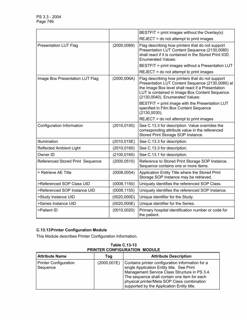
PS 3.3 - 2004 Page 746
BESTFIT = print images without the Overlay(s) REJECT = do not attempt to print images
Presentation LUT Flag (2000,0069) Flag describing how printers that do not support Presentation LUT Content Sequence (2130,0080) shall react if it is contained in the Stored Print IOD. Enumerated Values: BESTFIT = print images without a Presentation LUTREJECT = do not attempt to print images
Image Box Presentation LUT Flag (2000,006A) Flag describing how printers that do not support Presentation LUT Content Sequence (2130,0080) at the Image Box level shall react if a Presentation LUT is contained in Image Box Content Sequence (2130,0040). Enumerated Values: BESTFIT = print image with the Presentation LUT specified in Film Box Content Sequence (2130,0030). REJECT = do not attempt to print images
Configuration Information (2010,0150) See C.13.3 for description. Value overrides the corresponding attribute value in the referenced Stored Print Storage SOP Instance.
Illumination (2010,015E) See C.13.3 for description. Reflected Ambient Light (2010,0160) See C.13.3 for description. Owner ID (2100,0160) See C.13.1 for description. Referenced Stored Print Sequence (2000,0510) Reference to Stored Print Storage SOP Instance.
Sequence contains one or more items. > Retrieve AE Title (0008,0054) Application Entity Title where the Stored Print
Storage SOP Instance may be retrieved. >Referenced SOP Class UID (0008,1150) Uniquely identifies the referenced SOP Class. >Referenced SOP Instance UID (0008,1155) Uniquely identifies the referenced SOP Instance. >Study Instance UID (0020,000D) Unique identifier for the Study. >Series Instance UID (0020,000E) Unique identifier for the Series. >Patient ID (0010,0020) Primary hospital identification number or code for
the patient.
C.13.13 Printer Configuration Module This Module describes Printer Configuration Information.
Table C.13-13 PRINTER CONFIGURATION MODULE
Attribute Name Tag Attribute Description Printer Configuration Sequence
(2000,001E) Contains printer configuration information for a single Application Entity title. See Print Management Service Class Structure in PS 3.4. The sequence shall contain one item for each physical printer/Meta SOP Class combination supported by the Application Entity title.

PS 3.3 - 2004 Page 747
>SOP Classes Supported (0008,115A) The Meta-SOP Class and a list of optional SOP Classes supported. It shall contain one Meta SOP Class UID and 0-n optional SOP Class UIDs.
>Maximum Memory Allocation (2000,0061) Maximum number of kilobytes of memory that can be allocated for a Film Session. The value shall be 0 if Memory Allocation (2000,0060) is not supported.
>Memory Bit Depth (2000,00A0) The maximum number of bits for each pixel that can be stored in printer memory.
>Printing Bit Depth (2000,00A1) The number of bits used by the print engine for internal LUT calculation and printing of each pixel.
>Media Installed Sequence (2000,00A2) A sequence which specifies the combinations of Medium Type and Film Size IDs available in the printer at this time and the Min and Max Densities supported by these media. The Item Number with the value of 1 is the printer default. There is no significance to other item numbers. One item for each Medium Type and Film Size ID installed shall be included.
>>Item Number (0020,0019) A number that labels this item. Each item in the sequence shall have a unique number.
>>Medium Type (2000,0030) See C.13.1 >>Film Size ID (2010,0050) See C.13.3 >>Min Density (2010,0120) Minimum density that can be printed, expressed in
hundredths of OD. >>Max Density (2010,0130) Maximum density that can be printed, expressed in
hundredths of OD. >Other Media Available Sequence
(2000,00A4) A sequence which specifies combinations of Medium Type and Film Size ID for which the printer will accept an N-CREATE of a Film Box, but are not physically installed in the printer at this time. It also specifies the Min and Max Densities supported by these media. User intervention may be required to instal these media in the printer. One item for each Medium Type and Film Size ID available, but not installed shall be included.
>>Medium Type (2000,0030) See C.13.1 >>Film Size ID (2010,0050) See C.13.3 >>Min Density (2010,0120) Minimum density that can be printed, expressed in
hundredths of OD. >>Max Density (2010,0130) Maximum density that can be printed, expressed in
hundredths of OD. >Supported Image Display Formats Sequence
(2000,00A8) A sequence which specifies the Image Display Formats supported, rows and columns in Image Boxes for each format, pixel spacing, and whether Requested Image Size is supported as a function of Film Orientation, Film Size ID, and Printer
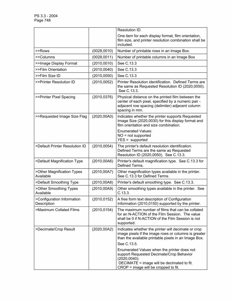
PS 3.3 - 2004 Page 748
Resolution ID. One item for each display format, film orientation, film size, and printer resolution combination shall be included.
>>Rows (0028,0010) Number of printable rows in an Image Box. >>Columns (0028,0011) Number of printable columns in an Image Box >>Image Display Format (2010,0010) See C.13.3 >>Film Orientation (2010,0040) See C.13.3 >>Film Size ID (2010,0050) See C.13.3 >>Printer Resolution ID (2010,0052) Printer Resolution identification. Defined Terms are
the same as Requested Resolution ID (2020,0050). See C.13.3.
>>Printer Pixel Spacing (2010,0376) Physical distance on the printed film between the center of each pixel, specified by a numeric pair - adjacent row spacing (delimiter) adjacent column spacing in mm.
>>Requested Image Size Flag (2020,00A0) Indicates whether the printer supports Requested Image Size (2020,0030) for this display format and film orientation and size combination. Enumerated Values: NO = not supported YES = supported
>Default Printer Resolution ID (2010,0054) The printer's default resolution identification. Defined Terms are the same as Requested Resolution ID (2020,0050). See C.13.3.
>Default Magnification Type (2010,00A6) Printer's default magnification type. See C.13.3 for Defined Terms.
>Other Magnification Types Available
(2010,00A7) Other magnification types available in the printer. See C.13.3 for Defined Terms.
>Default Smoothing Type (2010,00A8) Printer's default smoothing type. See C.13.3. >Other Smoothing Types Available
(2010,00A9) Other smoothing types available in the printer. See C.13.3.
>Configuration Information Description
(2010,0152) A free form text description of Configuration Information (2010,0150) supported by the printer.
>Maximum Collated Films (2010,0154) The maximum number of films that can be collated for an N-ACTION of the Film Session. The value shall be 0 if N-ACTION of the Film Session is not supported.
>Decimate/Crop Result (2020,00A2) Indicates whether the printer will decimate or crop image pixels if the image rows or columns is greater than the available printable pixels in an Image Box. See C.13.5. Enumerated Values when the printer does not support Requested Decimate/Crop Behavior (2020,0040): DECIMATE = image will be decimated to fit. CROP = image will be cropped to fit.
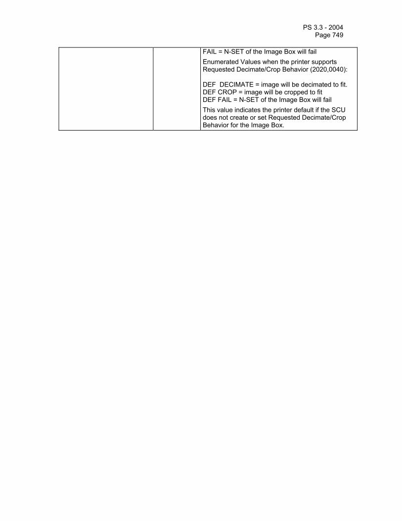
PS 3.3 - 2004 Page 749
FAIL = N-SET of the Image Box will fail Enumerated Values when the printer supports Requested Decimate/Crop Behavior (2020,0040): DEF DECIMATE = image will be decimated to fit. DEF CROP = image will be cropped to fit DEF FAIL = N-SET of the Image Box will fail This value indicates the printer default if the SCU does not create or set Requested Decimate/Crop Behavior for the Image Box.

PS 3.3 - 2004 Page 750
C.14 STORAGE COMMITMENT MODULE
Table C.14-1 defines the Attributes for referencing SOP Instances which are contained in a Storage Commitment Request/Response.
Table C.14-1 STORAGE COMMITMENT MODULE ATTRIBUTES
Attribute Name Tag Attribute Description Transaction UID (0008,1195) Uniquely identifies this Storage Commitment
transaction. Retrieve AE Title (0008,0054) Application Entity Title where the SOP Instance(s)
may be retrieved via a network based retrieve service.
Storage Media File-Set ID (0088,0130) User or implementation specific human readable identification of a Storage Media on which the SOP Instances reside.
Storage Media File-Set UID (0088,0140) Uniquely identifies a Storage Media on which the SOP Instances reside.
Referenced SOP Sequence (0008,1199) A sequence of repeating Items where each Item references a single SOP Instance for which storage commitment is requested / or has been provided.
>Referenced SOP Class UID (0008,1150) Uniquely identifies the referenced SOP Class. >Referenced SOP Instance UID (0008,1155) Uniquely identifies the referenced SOP Instance. >Retrieve AE Title (0008,0054) Application Entity Title from which the SOP Instance
may be retrieved via a network based retrieve service.
>Storage Media File-Set ID (0088,0130) The user or implementation specific human readable identifier that identifies a Storage Media on which this SOP Instance resides.
>Storage Media File-Set UID (0088,0140) Uniquely identifies a Storage Media on which this SOP Instance resides.
Failed SOP Sequence (0008,1198) A sequence of repeating Items where each Item references a single SOP Instance for which storage commitment could not be provided.
>Referenced SOP Class UID (0008,1150) Uniquely identifies the referenced SOP Class. >Referenced SOP Instance UID (0008,1155) Uniquely identifies the referenced SOP Instance. >Failure Reason (0008,1197) The reason that storage commitment could not be
provided for this SOP Instance. See Section C.14.1.1.
Notes: 1. Conditions under which Attributes are required (i.e. Retrieve AE Title, etc.) are defined in the Storage Commitment Service Class in PS 3.4.
2. Referenced Performed Procedure Step Sequence (0008,1111) was included in this Module in earlier versions, but its use here has been retired. See PS 3.4-2001, in which the Attribute was formerly known as Referenced Study Component Sequence.

PS 3.3 - 2004 Page 751
C.14.1 Storage Commitment Attribute Description C.14.1.1 Failure Reason The following values and semantics shall be used for the Failure Reason Attribute :
0110H - Processing failure A general failure in processing the operation was encountered.
0112H - No such object instance One or more of the elements in the Referenced SOP Instance Sequence was not available.
0213H - Resource limitation The SCP does not currently have enough resources to store the requested SOP Instance(s).
0122H - Referenced SOP Class not supported Storage Commitment has been requested for a SOP Instance with a SOP Class that is not supported by the SCP.
0119H - Class / Instance conflict The SOP Class of an element in the Referenced SOP Instance Sequence did not correspond to the SOP class registered for this SOP Instance at the SCP.
0131H - Duplicate transaction UID The Transaction UID of the Storage Commitment Request is already in use.
C.15 QUEUE MANAGEMENT SPECIFIC MODULES
C.15.1 General Queue Module Table C.15-1
GENERAL QUEUE MODULE ATTRIBUTES Attribute Name Tag Description Queue Status (2120,0010) Status of the queue; Defined Terms:
NORMAL = queue can accept new jobs FULL = queue is full, new jobs cannot be accepted, however existing jobs are being processed by the SCP HALTED = queue is halted (e.g. by a service person), new jobs cannot be accepted, existing jobs may or may not be processed and reprioritizing and deletion of jobs may or may not be accepted by the SCP

PS 3.3 - 2004 Page 752
C.15.2 Print Queue Module
Table C.15-2 PRINT GENERAL QUEUE MODULE ATTRIBUTES
Attribute Name Tag Description Print Job Description Sequence (2120,0050) A list of Attributes describing each Print Job in the
queue. Zero or more items shall be included in this sequence. Items in this sequence shall be listed in the following order:
Print Job now being printed Pending Print Jobs in the order in which they
are expected to be printed Any Print Jobs which have failed and will not
be printed Any Print Jobs which have been successfully
competed It is not a requirement that the SCP maintain a record and report failed and completed jobs. However, it may choose to maintain and report on these Print Jobs for some time after the Print Jobs have been completed or failed.
>Print Job ID (2100,0010) Human readable identification of the Print Job. The ID shall be unique in the context of the Print Job Sequence.
>Execution Status (2100,0020) See Execution Status in Section C.13.8. >Execution Status Info (2100,0030) See Execution Status Info in Section C.13.8. >Creation Date (2100,0040) Date of print job creation. >Creation Time (2100,0050) Time of print job creation. >Print Priority (2000,0020) See Table C.13-1. >Originator (2100,0070) Application Entity Title that issued the print job. >Destination AE (2100,0140) Application Entity Title that performs the print job. >Printer Name (2110,0030) User defined name identifying the printer. >Film Destination (2000,0040) See Table C.13-1. >Film Session Label (2000,0050) Human readable label that identifies the film
session. >Owner ID (2100,0160) Identification of the owner of the film session. >Medium Type (2000,0030) See Table C.13-1. >Number Of Films (2100,0170) Number of films in print job (= number of films in film
session times number of copies). >Referenced Print Job Sequence (2120,0070) A sequence which provides references to the
corresponding Print Job SOP Class/Instance pair. Only a single Item shall be permitted in this sequence.
>>Referenced SOP Class UID (0008,1150) Uniquely identifies the Referenced SOP Class.

PS 3.3 - 2004 Page 753
>>Referenced SOP Instance UID (0008,1155) Uniquely identifies the Referenced SOP Instance.
C.16 STORED PRINT SPECIFIC MODULES
The following Modules are used by the Stored Print IOD.
C.16.1 Printer Characteristics Module Table C.16-1 specifies the Attributes that identify characteristics of a device that printed the Film Box.
Table C.16-1 PRINTER CHARACTERISTICS MODULE ATTRIBUTES
Attribute Name Tag Type Description Print Management Capabilities Sequence
(2130,0010) 1 A list of Print Management SOP Classes (e.g. Film Session SOP Class, Basic Annotation Box) and Image Storage SOP Classes (e.g. US Image, Hardcopy Grayscale Image) that the Stored Print IOD contains or refers to. One or more Items shall be included in this sequence.
>Referenced SOP Class UID (0008,1150) 1 SOP Class UID of the SOP Class, that the Stored Print IOD contains or refers to.
Printer Characteristics Sequence (2130,0015) 2 Printer Characteristics information. Only valid if film session/box has been printed. One Item shall be included in this sequence.
>Creation Date (2100,0040) 3 Date of print job creation. >Creation Time (2100,0050) 3 Time of print job creation. >Originator (2100,0070) 2 Application Entity Title that issued the print
operation. >Destination AE (2100,0140) 2 Application Entity Title that performed the
print operation. >Printer Name (2110,0030) 3 User defined name identifying the printer. >Manufacturer (0008,0070) 3 Manufacturer of the printer. >Manufacturer Model Name (0008,1090) 3 Manufacturer's Model Name of the printer. >Device Serial Number (0018,1000) 3 Manufacturer’s serial number of the printer.>Software Version (0018,1020) 3 Manufacturer’s designation of software
version of the printer. >Date of Last Calibration (0018,1200) 3 Date when the printer was last calibrated. >Time of Last Calibration (0018,1201) 3 Time when the printer was last calibrated.

PS 3.3 - 2004 Page 754
C.16.2 Film Box Module Table C.16-2 specifies the Attributes that identify characteristics of a Film Box.
Table C.16-2 FILM BOX MODULE ATTRIBUTES
Attribute Name Tag Type Description Instance Number (0020,0013) 2 A number that identifies this film box. Film Box Content Sequence (2130,0030) 1 The content of the Film Box SOP Instance.
One Item shall be included in this sequence.
>Image Display Format (2010,0010) 1 See C.13.3 for description. >Annotation Display Format ID (2010,0030) 3 See C.13.3 for description. >Film Orientation (2010,0040) 2 See C.13.3 for description. >Film Size ID (2010,0050) 2 See C.13.3 for description. >Magnification Type (2010,0060) 2 See C.13.3 for description. >Smoothing Type (2010,0080) 3 See C.13.3 for description. >Border Density (2010,0100) 3 See C.13.3 for description. >Empty Image Density (2010,0110) 3 See C.13.3 for description. >Min Density (2010,0120) 3 See C.13.3 for description. >Max Density (2010,0130) 2 See C.13.3 for description. >Trim (2010,0140) 3 See C.13.3 for description. >Configuration Information (2010,0150) 2 See C.13.3 for description. >Illumination (2010,015E) 2C See C.13.3 for description. Required if
Presentation SOP Class is present. >Reflected Ambient Light (2010,0160) 2C See C.13.3 for description. Required if
Presentation SOP Class is present. >Requested Resolution ID (2020,0050) 3 See C.13.3 >Referenced Presentation LUT Sequence
(2050,0500) 1C Reference to a LUT Instance UID contained in this IOD in Presentation LUT Content Sequence (2130,0080). The referenced LUT is to be applied to all images on this film, unless overridden by another reference contained in Image Box Content Sequence (2130,0040). If included, this sequence shall contain a single item. Required if a Presentation LUT is to be applied to the image.
>>Referenced SOP Instance UID (0008,1155) 1C Uniquely identifies the referenced SOP Instance; Required if Referenced Presentation LUT Sequence is present.

PS 3.3 - 2004 Page 755
C.16.3 Image Box List Module Table C.16-3
IMAGE BOX LIST MODULE ATTRIBUTES Attribute Name Tag Type Description
Image Box Content Sequence (2130,0040) 1 The content of the Image Box SOP Instance. One or more Items shall be included in this sequence.
>SOP Instance UID (0008,0018) 1C SOP Instance UID of the contained Image Box SOP Class. Required if Sequence is sent
>Image Position (2020,0010) 1 See C.13.5 for description. >Polarity (2020,0020) 2 See C.13.5 for description. >Magnification Type (2010,0060) 3 See C.13.5 for description. >Configuration Information (2010,0150) 3 See C.13.3 for description. The This value
overrides any Configuration Information in Film Box Content Sequence (2130,0030)
>Smoothing Type (2010,0080) 3 See C.13.5 for description. >Requested Image Size (2020,0030) 3 See C.13.5 for description. >Requested Decimate/Crop Behavior (2020,0040) 3 See C.13.5 >Referenced Image Sequence (0008,1140) 1 A Sequence which provides references to
an Image SOP Class/Instance pair and a specific frame in multi-frame instances. Only a single item shall be permitted in this Sequence.
>>Retrieve AE Title (0008,0054) 1 Application Entity Title where the Image Storage SOP Instance may be retrieved
>>Referenced SOP Class UID (0008,1150) 1 Uniquely identifies the referenced SOP Class.
>>Referenced SOP Instance UID (0008,1155) 1 Uniquely identifies the referenced SOP Instance.
>>Study Instance UID (0020,000D) 1 Unique identifier for the Study >>Series Instance UID (0020,000E) 1 Unique identifier for the Series >>Referenced Frame Number (0008,1160) 1C Identifies the frame in the referenced multi-
frame image referenced by this Image Sequence. Frame Number shall be increasing sequential order beginning with the value 1. Required if a Multi-frame Image is being referenced.
>>Patient ID (0010,0020) 2 Primary hospital identification number or code for the patient
>Referenced Image Overlay Box Sequence
(2020,0130) 1C Reference to an Overlay Instance UID contained in this IOD in Image Overlay Box Content Sequence (2130,0060). If included, this sequence shall contain a single item.

PS 3.3 - 2004 Page 756
Required if Image Overlay Box Content Sequence (2130,0060) is present.
>>Referenced SOP Instance UID (0008,1155) 1C Uniquely identifies the Referenced SOP Instance. Required if Referenced Image Overlay Box Sequence is sent.
>Referenced Presentation LUT Sequence
(2050,0500) 1C Reference to a LUT Instance UID contained in this IOD in Presentation LUT Content Sequence (2130,0080). The referenced LUT overrides any LUT Instance contained in Film Box Content Sequence (2130,0030) If included, this sequence shall contain a single item. Required if a Presentation LUT which is different than any specified for the Film Box is to be applied to the image.
>>Referenced SOP Instance UID (0008,1155) 1C Uniquely identifies the referenced SOP Instance; Required if Referenced Presentation LUT Sequence is present.
C.16.4 Annotation List Module Table C.16-4
ANNOTATION LIST MODULE ATTRIBUTES Attribute Name Tag Type Description
Annotation Content Sequence (2130,0050) 3 The content of the Annotation SOP Instance. Zero or more Items shall be included in this sequence.
>SOP Instance UID (0008,0018) 1C SOP Instance UID of the contained Annotation SOP Class. Required if Sequence is sent.
>Annotation Position (2030,0010) 1C See C.13.7 for description. Required if the Annotation Content Sequence is sent.
>Text String (2030,0020) 1C See C.13.7 for description. Required if the Annotation Content Sequence is sent.
C.16.5 Image Overlay Box List Module Table C.16-5
IMAGE OVERLAY BOX LIST MODULE ATTRIBUTES Attribute Name Tag Type Description
Image Overlay Box Content Sequence (2130,0060) 3 The content of the Image Overlay Box SOP Instance. If sent, one or more Items shall be included in this sequence.
>SOP Instance UID (0008,0018) 1C SOP Instance UID of the contained Image Overlay Box SOP Class. Required if Sequence is sent.
>Overlay Pixel Data Sequence (2040,0020) 1C A sequence which provides overlay pixel data. A single item shall be present.

PS 3.3 - 2004 Page 757
Required if Sequence is sent. >>Overlay Rows (6000,0010) 1C See C.9.2 Required if Sequence is sent. >>Overlay Columns (6000,0011) 1C See C.9.2 Required if Sequence is sent. >>Overlay Origin (6000,0050) 1C See C.9.2 Required if Sequence is sent. >>Overlay Bits Allocated (6000,0100) 1C See C.9.5. Required if Sequence is sent. >>Overlay Bit Position (6000,0102) 1C See C. 9.5. Required if Sequence is sent. >>Overlay Data (6000,3000) 1C See C. 9.5. Required if Sequence is sent. >Overlay or Image Magnification (2040,0072) 1C See C. 9.5. Required if Magnify to Number
of Columns (2040,0074) is present. >Magnify to Number of Columns (2040,0074) 1C See C. 9.5. Required if Overlay or Image
Magnification (2040,0072) is present. >Overlay Magnification Type (2040,0060) 3 See C.9.5. >Overlay Smoothing Type (2040,0070) 3 See C.9.5. >Overlay Foreground Density (2040,0080) 3 See C.9.5. >Overlay Background Density (2040,0082) 3 See C.9.5.
Referenced Overlay Plane Sequence (2040,0010), Referenced SOP Class UID (0008,1150), Referenced SOP Instance UID (0008,1155), Referenced Frame Number (0008,1160), Referenced Overlay Plane Groups (2040,0011), Overlay Mode (2040,0090), and Threshold Density (2040,0100) were previously Attributes in this Module. They have been retired from this Module. See PS 3.3-1998.
C.16.6 Presentation LUT List Module Table C.16-6
PRESENTATION LUT LIST MODULE ATTRIBUTES Attribute Name Tag Type Description
Presentation LUT Content Sequence (2130,0080) 3 The content of the Presentation LUT SOP Instance. If sent, one or more Items shall be included in this sequence.
>SOP Instance UID (0008,0018) 1C SOP Instance UID of the contained Presentation LUT SOP Class. Required if Sequence is sent
>Presentation LUT Sequence (2050,0010) 1C See C.11.4 for description; Required if Presentation LUT Shape (2050,0020) is not present. Not allowed otherwise.
>>LUT Descriptor (0028,3002) 1C See C.11.4 for description; Required if Presentation LUT Sequence is sent.
>>LUT Explanation (0028,3003) 3 See C.11.4 for description; >>LUT Data (0028,3006) 1C See C.11.4 for description; Required if
Presentation LUT Sequence is sent. >Presentation LUT Shape (2050,0020) 1C See C.11.4 for description; Required if
Presentation LUT Sequence (2050,0010) is not present. Not allowed otherwise. SCPs shall support the Enumerated Values IDENTITY and LIN OD

PS 3.3 - 2004 Page 758
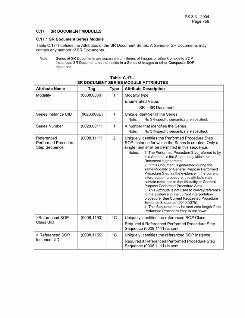
PS 3.3 - 2004 Page 759
C.17 SR DOCUMENT MODULES
C.17.1 SR Document Series Module Table C.17-1 defines the Attributes of the SR Document Series. A Series of SR Documents may contain any number of SR Documents.
Note: Series of SR Documents are separate from Series of Images or other Composite SOP Instances. SR Documents do not reside in a Series of Images or other Composite SOP Instances.
Table C.17-1
SR DOCUMENT SERIES MODULE ATTRIBUTES Attribute Name Tag Type Attribute Description Modality (0008,0060) 1 Modality type.
Enumerated Value: SR = SR Document
Series Instance UID (0020,000E) 1 Unique identifier of the Series. Note: No SR-specific semantics are specified.
Series Number (0020,0011) 1 A number that identifies the Series. Note: No SR-specific semantics are specified.
Referenced Performed Procedure Step Sequence
(0008,1111) 2 Uniquely identifies the Performed Procedure Step SOP Instance for which the Series is created. Only a single Item shall be permitted in this sequence.
Notes: 1. The Performed Procedure Step referred to by this Attribute is the Step during which this Document is generated. 2. If this Document is generated during the same Modality or General Purpose Performed Procedure Step as the evidence in the current interpretation procedure, this attribute may contain reference to that Modality or General Purpose Performed Procedure Step. 3. This Attribute is not used to convey reference to the evidence in the current interpretation procedure. See Current Requested Procedure Evidence Sequence (0040,A375). 4. This Sequence may be sent zero length if the Performed Procedure Step is unknown.
>Referenced SOP Class UID
(0008,1150) 1C Uniquely identifies the referenced SOP Class. Required if Referenced Performed Procedure Step Sequence (0008,1111) is sent.
> Referenced SOP Instance UID
(0008,1155) 1C Uniquely identifies the referenced SOP Instance. Required if Referenced Performed Procedure Step Sequence (0008,1111) is sent.

PS 3.3 - 2004 Page 760
C.17.2 SR Document General Module Table C.17-2 defines the general Attributes of an SR Document Instance. These Attributes identify the SR Document and provide context for the entire document.
Table C.17-2 SR DOCUMENT GENERAL MODULE ATTRIBUTES
Attribute Name Tag Type Attribute Description Instance Number (0020,0013) 1 A number that identifies the SR Document. Completion Flag (0040,A491) 1 The estimated degree of completeness of
this SR Document with respect to externally defined criteria in a manner specified in the Conformance Statement.
Note: It may be desirable to make these criteria adaptable to local policies or user decisions.
Enumerated Values: PARTIAL = Partial content. COMPLETE = Complete content.
Completion Flag Description (0040,A492) 3 Explanation of the value sent in Completion Flag (0040,A491).
Verification Flag (0040,A493) 1 Indicates whether this SR Document is Verified. Enumerated Values: UNVERIFIED = Not attested to. VERIFIED = Attested to by a Verifying Observer Name (0040,A075) who is accountable for its content.
Note: The intent of this specification is that the "prevailing final version" of an SR Document is the version having the most recent Verification DateTime (0040,A030), Completion Flag (0040,A491) of COMPLETE and Verification Flag (0040,A493) of VERIFIED.
Content Date (0008,0023) 1 The date the document content creation started.
Content Time (0008,0033) 1 The time the document content creation started.
Verifying Observer Sequence (0040,A073) 1C The person or persons authorized to verify documents of this type and accept responsibility for the content of this document. One or more Items may be included in this sequence. Required if Verification Flag (0040,A493) is VERIFIED.
>Verifying Observer Name (0040,A075) 1 The person authorized by the Verifying Organization (0040,A027) to verify documents of this type and who accepts responsibility for the content of this document

PS 3.3 - 2004 Page 761
>Verifying Observer Identification Code Sequence
(0040,A088) 2 Coded identifier of Verifying Observer. Zero or one Items shall be permitted in this sequence.
>>Include 'Code Sequence Macro' Table 8.8-1 >Verifying Organization (0040,A027) 1 Organization to which the Verifying
Observer Name (0040,A075) is accountable for this document in the current interpretation procedure.
>Verification DateTime (0040,A030) 1 Date and Time of verification by the Verifying Observer Name (0040,A075).
Predecessor Documents Sequence
(0040,A360) 1C Shall refer to SR SOP Instances (e.g. prior or provisional reports) whose content has been wholly or partially included in this document with or without modification. One or more Items may be included in this sequence. Required if this document includes content from other documents.
Note: The amendment process of an existing SR Document is not explicitly described, but several approaches may be considered. One may choose, for example, to create a new SR Document that includes the original content with any amendments applied or included. The structure of this amended SR Document may or may not reflect what was amended. However, the use of the Predecessor Document Sequence allows tracing back to the input SR Document, which in this case is the previous version.
>Include 'SOP Instance Reference Macro' Table C.17-3 Identical Documents Sequence (0040,A525) 1C Duplicates of this document, stored with
different SOP Instance UIDs. One or more Items may be included in this sequence. Required if this document is stored with different SOP Instance UIDs in one or more other Studies. See C.17.2.2 for further explanation.
>Include 'SOP Instance Reference Macro' Table C.17-3 Referenced Request Sequence (0040,A370) 1C Identifies Requested Procedures which are
being fulfilled (completely or partially) by creation of this Document. One or more Items may be included in this sequence. Required if this Document fulfills at least one Requested Procedure.
>Study Instance UID (0020,000D) 1 Unique identifier for the Study. >Referenced Study Sequence (0008,1110) 2 Uniquely identifies the Study SOP Instance.
Only a single Item shall be permitted in this

PS 3.3 - 2004 Page 762
sequence. >>Referenced SOP Class UID (0008,1150) 1 Uniquely identifies the SOP Class >>Referenced SOP Instance UID
(0008,1155) 1 Uniquely identifies the SOP Instance.
>Accession Number (0008,0050) 2 A departmental IS generated number which identifies the order for the Study.
>Placer Order Number/Imaging Service Request
(0040,2016) 2 The order number assigned to the Imaging Service Request by the party placing the order.
>Filler Order Number/Imaging Service Request
(0040,2017) 2 The order number assigned to the Imaging Service Request by the party filling the order.
>Requested Procedure ID (0040,1001) 2 Identifier of the related Requested Procedure
>Requested Procedure Description
(0032,1060) 2 Institution-generated administrative description or classification of Requested Procedure.
>Requested Procedure Code Sequence
(0032,1064) 2 A sequence that conveys the requested procedure. Zero or one Item may be included in this sequence.
>>Include 'Code Sequence Macro' Table 8.8-1 No Baseline Context ID Number is specified. >Reason for the Requested Procedure
(0040,1002) 3 Reason for requesting this procedure.
>Reason for Requested Procedure Code Sequence
(0040,100A) 3 Coded Reason for requesting this procedure.
>>Include 'Code Sequence Macro' Table 8.8-1 No Baseline Context ID Number is specified. Performed Procedure Code Sequence
(0040,A372) 2 A Sequence that conveys the codes of the performed procedures pertaining to this SOP Instance. Zero or more Items may be included in this sequence.
>Include 'Code Sequence Macro' Table 8.8-1 No Baseline Context ID Number is specified. Current Requested Procedure Evidence Sequence
(0040,A375) 1C Full set of Composite SOP Instances created to satisfy the current Requested Procedure(s) for which this SR Document is generated. One or more Items may be included in this sequence. Required if Composite Objects were acquired in order to satisfy the Requested Procedure(s) for which the SR Document is generated and Completion Flag (0040,A491) value is COMPLETE. May be present otherwise. See C.17.2.3 for further explanation.
>Include 'SOP Instance Reference Macro' Table C.17-3 Pertinent Other Evidence Sequence
(0040,A385) 1C Other Composite SOP Instances that are considered to be pertinent evidence by the creator of this SR Document. This evidence must have been acquired in order to satisfy Requested Procedures other than the

PS 3.3 - 2004 Page 763
one(s) for which this SR Document is generated. One or more Items may be included in this sequence. Required if pertinent evidence from other Requested Procedures needs to be recorded. See C.17.2.3 for further explanation.
>Include 'SOP Instance Reference Macro' Table C.17-3
C.17.2.1 SOP Instance Reference Macro Table C.17-3 specifies the Attributes that reference a SOP Instance.
Table C.17-3 SOP INSTANCE REFERENCE MACRO ATTRIBUTES
Attribute Name Tag Type Attribute Description Study Instance UID (0020,000D) 1 Unique identifier for the Study Referenced Series Sequence (0008,1115) 1 Sequence of Repeating Items where each
Item includes the Attributes of a Series containing referenced Composite Object(s). One or more Items may be included in this sequence
>Series Instance UID (0020,000E) 1 Unique identifier of a Series that is part of this Study and contains the referenced Composite Object(s).
>Retrieve AE Title (0008,0054) 3 Title of the DICOM Application Entity where the Composite Object(s) may be retrieved on the network.
>Storage Media File-Set ID (0088,0130) 3 The user or implementation specific human readable identifier that identifies the Storage Media on which the Composite Object (s) reside.
>Storage Media File-Set UID (0088,0140) 3 Uniquely identifies the Storage Media on which the Composite Object (s) reside.
>Referenced SOP Sequence (0008,1199) 1 References to Composite Object SOP Class/SOP Instance pairs that are part of the Study defined by Study Instance UID and the Series defined by Series Instance UID (0020,000E). One or more Items may be included in this sequence
>>Referenced SOP Class UID (0008,1150) 1 Uniquely identifies the referenced SOP Class.>>Referenced SOP Instance UID
(0008,1155) 1 Uniquely identifies the referenced SOP Instance.
C.17.2.2 Identical Documents Sequence If identical copies of an SR Document are to be included in multiple Studies then the entire SR Document shall be duplicated with appropriate changes for inclusion into the different Studies (i.e. Study Instance UID, Series Instance UID, SOP Instance UID, Identical Documents Sequence etc.). The Identical Documents Sequence Attribute in each SOP Instance shall contain references to all other duplicate SOP Instances.

PS 3.3 - 2004 Page 764
Note: If an SR Document contains an Identical Documents Sequence then it will not be further duplicated without producing a new complete set of duplicate SOP Instances with re-generated Identical Documents Sequences. This is a consequence of the rules for modification of SR Document content in PS3.4. For example, if there are two identical reports and an application is creating a third identical report, then the first two reports must be re-generated in order that their Identical Documents Sequence will reference the new duplicate document and all other identical documents.
If a new SR Document is created using content from an SR Document that contains an Identical Documents Sequence and is part of the same Requested Procedure, then the new SR Document shall only contain a new Identical Documents Sequence if the new SR Document is duplicated. The Predecessor Documents Sequence in all the new SR Documents shall contain references to the original SR Document and all its duplicates as well as any other documents from which content is included.
Note: It is up to an implementation to decide whether a new SR Document is duplicated across multiple Studies. This may require user input to make the decision.
C.17.2.3 Current Requested Procedure Evidence Sequence and Pertinent Other Evidence Sequence The intent of the Current Requested Procedure Evidence Sequence is to reference all evidence created in order to satisfy the current Requested Procedure(s) for this SR Document. This shall include, but is not limited to, all current evidence referenced in the content tree.
For a completed SR Document satisfying (i.e., being the final report for) the current Requested Procedure(s), this sequence shall list the full set of Composite SOP Instances created for the current Requested Procedure(s). For other SOP Instances that include the SR Document General Module, this sequence shall contain at minimum the set of Composite SOP Instances from the current Requested Procedure(s) that are referenced in the content tree.
The Pertinent Other Evidence Sequence attribute is used to reference all other evidence considered pertinent for this SR Document that is not listed in the Current Requested Procedure Evidence Sequence.
This requires that the same SOP Instance shall not be referenced in both of these Sequences.
C.17.3 SR Document Content Module This section specifies the Attributes contained in the SR Document Content Module. The Attributes in this Module convey the content of an SR Document.
Table C.17-4 SR DOCUMENT CONTENT MODULE ATTRIBUTES
Attribute Name Tag Type Attribute Description Include Document Content Macro Table C.17-5. with a Value Type (0040,A040) of CONTAINER Include Document Relationship Macro Table C.17-6.
Table C.17-5 DOCUMENT CONTENT MACRO ATTRIBUTES
Attribute Name Tag Type Attribute Description Value Type (0040,A040) 1 The type of the value encoded in this
Content Item.

PS 3.3 - 2004 Page 765
Defined Terms: TEXT NUM CODE DATETIME DATE TIME UIDREF PNAME COMPOSITE IMAGE WAVEFORM SCOORD TCOORD CONTAINER See C.17.3.2.1 for further explanation.
Concept Name Code Sequence (0040,A043) 1C Code describing the concept represented by this Content Item. Also conveys the value of Document Title and section headings in documents. Only a single Item shall be permitted in this sequence. Required if Value Type (0040,A040) is TEXT or NUM or CODE or DATETIME or DATE or TIME or UIDREF or PNAME. Required if Value Type (0040,A040) is CONTAINER and a heading is present, or this is the Root Content Item.
Note: That is, containers without headings do not require Concept Name Code Sequence
Required if Value Type (0040,A040) is COMPOSITE, IMAGE, WAVEFORM, SCOORD or TCOORD, and the Purpose of Reference is conveyed in the Concept Name. See C.17.3.2.2 for further explanation.
>Include 'Code Sequence Macro' Table 8.8-1 No Baseline Context ID. Continuity of Content (0040,A050) 1C This flag specifies for a CONTAINER
whether or not its contained Content Items are logically linked in a continuous textual flow, or are separate items. Required if Value Type (0040,A040) is CONTAINER. Enumerated Values: SEPARATE CONTINUOUS See C.17.3.2.3 for further explanation.
Text Value (0040,A160) 1C This is the value of the Content Item. Required if Value Type (0040,A040) is TEXT.

PS 3.3 - 2004 Page 766
Text data which is unformatted and whose manner of display is implementation dependent. The text value may contain spaces, as well as multiple lines separated by either LF, CR, CR LF or LF CR, but otherwise no format control characters (such as horizontal or vertical tab and form feed) shall be present, even if permitted by the Value Representation of UT. The text shall be interpreted as specified by Specific Character Set (0008,0005) if present in the SOP Common Module.
Note: The text may contain single or multi-byte characters and use code extension techniques as described in PS 3.5 if permitted by the values of Specific Character Set (0008,0005).
DateTime (0040,A120) 1C This is the value of the Content Item. Required if Value Type (0040,A040) is DATETIME.
Date (0040,A121) 1C This is the value of the Content Item. Required if Value Type (0040,A040) is DATE.
Time (0040,A122) 1C This is the value of the Content Item. Required if Value Type (0040,A040) is TIME.
Person Name (0040,A123) 1C This is the value of the Content Item. Required if Value Type (0040,A040) is PNAME.
UID (0040,A124) 1C This is the value of the Content Item. Required if Value Type (0040,A040) is UIDREF.
Include 'Numeric Measurement Macro' Table C.18.1-1 if and only if Value Type (0040,A040) is NUM. Include 'Code Macro' Table C.18.2-1 if and only if Value Type (0040,A040) is CODE. Include 'Composite Object Reference Macro' Table C.18.3-1 if and only if Value Type (0040,A040) is COMPOSITE. Include 'Image Reference Macro' Table C.18.4-1 if and only if Value Type (0040,A040) is IMAGE. Include 'Waveform Reference Macro' Table C.18.5-1 if and only if Value Type (0040,A040) is WAVEFORM. Include 'Spatial Coordinates Macro' Table C.18.6-1 if and only if Value Type (0040,A040) is SCOORD. Include 'Temporal Coordinates Macro' Table C.18.7-1 if and only if Value Type (0040,A040) is TCOORD.

PS 3.3 - 2004 Page 767
Table C.17-6 DOCUMENT RELATIONSHIP MACRO ATTRIBUTES
Attribute Name Tag Type Attribute Description Observation DateTime (0040,A032) 1C The date and time on which this Content
Item was completed. For the purpose of recording measurements or logging events, completion time is defined as the time of data acquisition of the measurement, or the time of occurrence of the event. Required if the date and time are different from the Content Date (0008,0023) and Content Time (0008,0033) or the Observation DateTime (0040,A032) defined in higher items. May be present otherwise.
Note: When Content Items are copied into successor reports, the Content Date (0008,0023) and Content Time (0008,0033) of the new report are likely to be different than the date and time of the original observation. Therefore this attribute may need to be included in any copied Content Items to satisfy the condition.
Content Template Sequence (0040,A504) 1C Template that describes the content of this Content Item. Only a single Item shall be permitted in this sequence. Required if a template was used to define the content of this Item, and the template consists of a single CONTAINER with nested content, and it is the outermost invocation of a set of nested templates that start with the same CONTAINER.
>Include 'Template Identification Macro' Table 9-1 No Baseline Template ID is defined. Content Sequence (0040,A730) 1C A potentially recursively nested Sequence
of Items that conveys content that is the Target of Relationships with the enclosing Source Content Item. One or more Items may be included in this sequence. Required if the enclosing Content Item has relationships.
Notes: 1. If this Attribute is not present then the enclosing Item is a leaf.
2. The order of Items within this Sequence is semantically significant for presentation.
See C.17.3.2.4 for further explanation. >Relationship Type (0040,A010) 1 The type of relationship between the
(enclosing) Source Content Item and the Target Content Item.
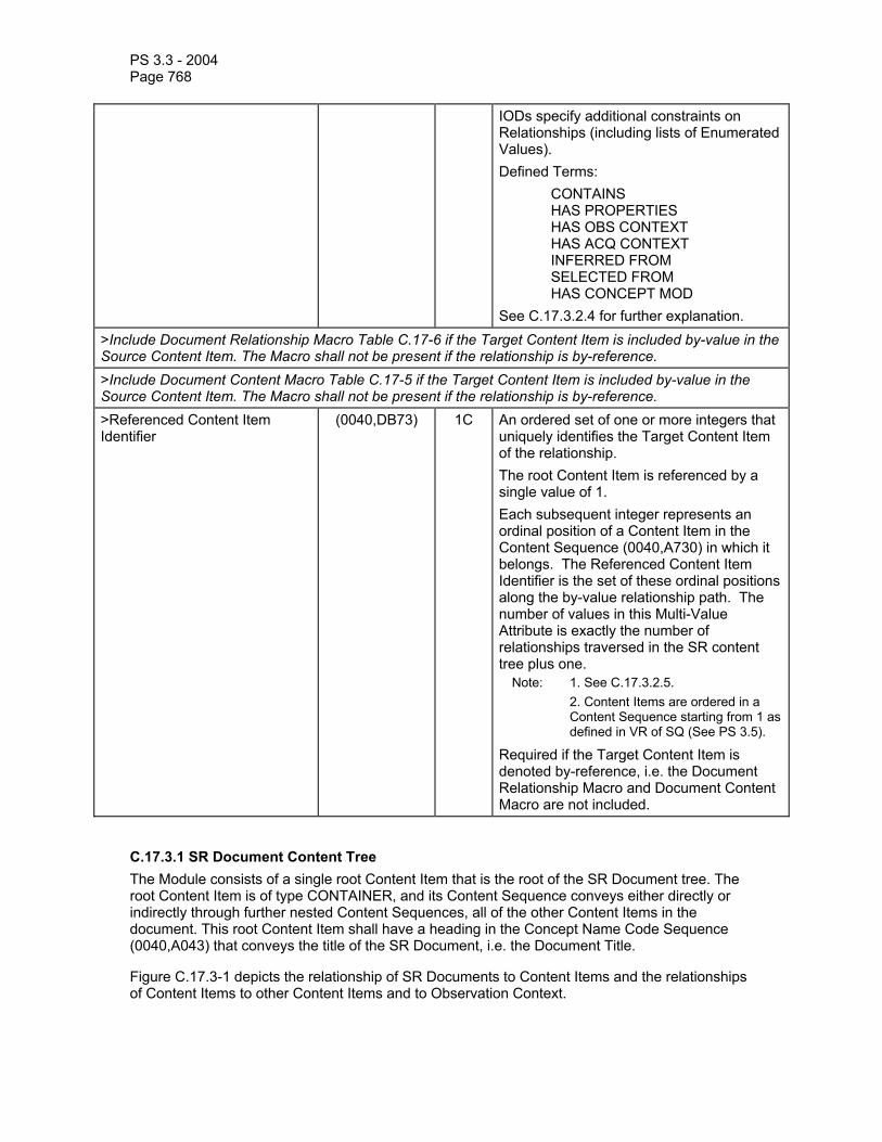
PS 3.3 - 2004 Page 768
IODs specify additional constraints on Relationships (including lists of Enumerated Values). Defined Terms: CONTAINS HAS PROPERTIES HAS OBS CONTEXT HAS ACQ CONTEXT INFERRED FROM SELECTED FROM HAS CONCEPT MOD See C.17.3.2.4 for further explanation.
>Include Document Relationship Macro Table C.17-6 if the Target Content Item is included by-value in the Source Content Item. The Macro shall not be present if the relationship is by-reference. >Include Document Content Macro Table C.17-5 if the Target Content Item is included by-value in the Source Content Item. The Macro shall not be present if the relationship is by-reference. >Referenced Content Item Identifier
(0040,DB73) 1C An ordered set of one or more integers that uniquely identifies the Target Content Item of the relationship. The root Content Item is referenced by a single value of 1. Each subsequent integer represents an ordinal position of a Content Item in the Content Sequence (0040,A730) in which it belongs. The Referenced Content Item Identifier is the set of these ordinal positions along the by-value relationship path. The number of values in this Multi-Value Attribute is exactly the number of relationships traversed in the SR content tree plus one.
Note: 1. See C.17.3.2.5. 2. Content Items are ordered in a
Content Sequence starting from 1 as defined in VR of SQ (See PS 3.5).
Required if the Target Content Item is denoted by-reference, i.e. the Document Relationship Macro and Document Content Macro are not included.
C.17.3.1 SR Document Content Tree The Module consists of a single root Content Item that is the root of the SR Document tree. The root Content Item is of type CONTAINER, and its Content Sequence conveys either directly or indirectly through further nested Content Sequences, all of the other Content Items in the document. This root Content Item shall have a heading in the Concept Name Code Sequence (0040,A043) that conveys the title of the SR Document, i.e. the Document Title.
Figure C.17.3-1 depicts the relationship of SR Documents to Content Items and the relationships of Content Items to other Content Items and to Observation Context.
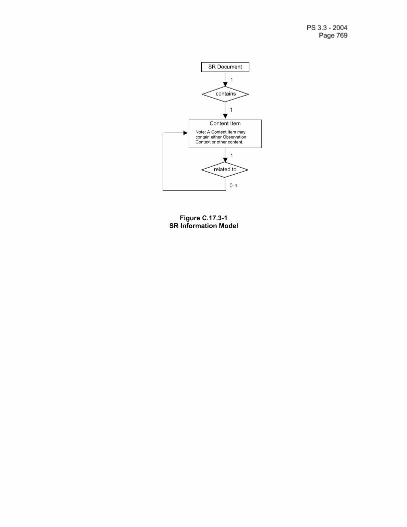
PS 3.3 - 2004 Page 769
contains
1
1
SR Document
Content Item
related to
1
0-n
Note: A Content Item may contain either Observation Context or other content.
Figure C.17.3-1 SR Information Model

PS 3.3 - 2004 Page 770
Content Item
Content Item
relationship
Content Item Content Item Content Item
relationship
Content Item
relationship relationship
Forbidden
Root Content Item
relationship
Content Item
Relationship
Content Item
relationship
relationship relationship relationship
relationship
* Relationship Modes BV = By-value BR = By-reference
Note: Whether or not relationships by-reference are allowed to ancestor Content Items, is specified in the IOD.
Figure C.17.3-2 – Example of an SR Content Tree (Informative)
C.17.3.2 Content Item Attributes Each Content Item contains:
- name/value pair, consisting of - a single Concept Name Code Sequence (0040,A043) that is the name of a
name/value pair or a heading, - a value (text, codes, etc.),
- references to images, waveforms or other composite objects, with or without coordinates, - relationships to other Items, either
- by-value through nested Content Sequences, or - by-reference.
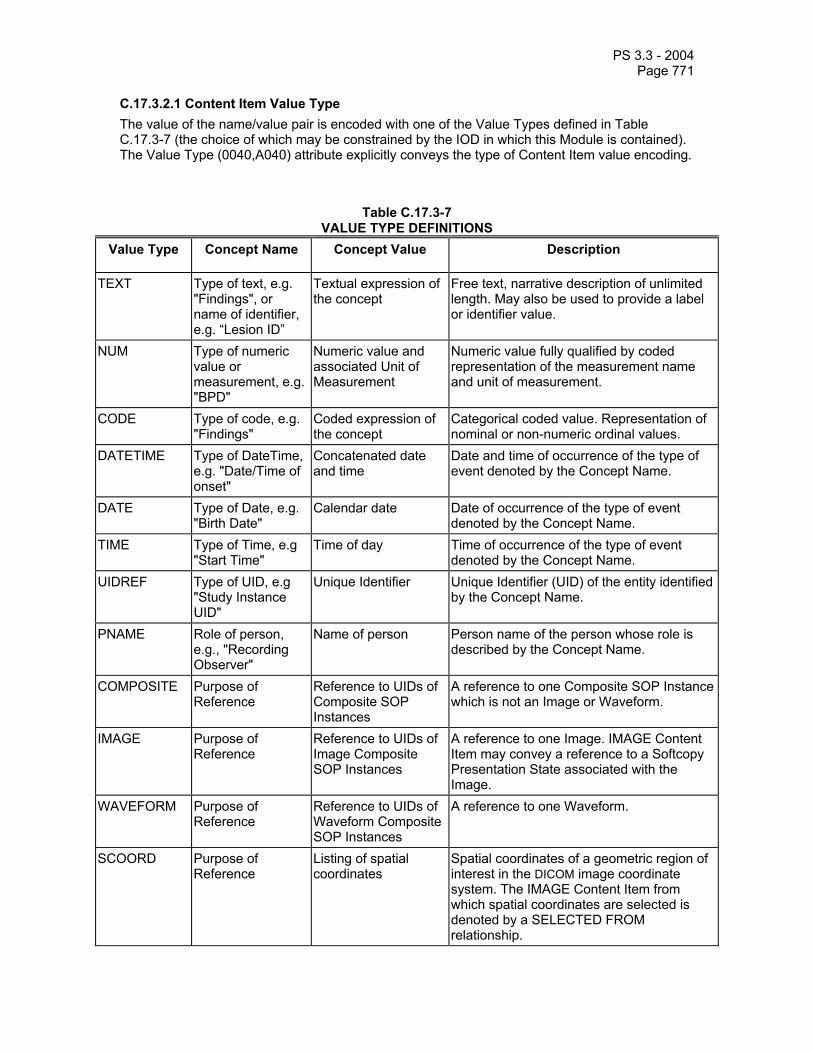
PS 3.3 - 2004 Page 771
C.17.3.2.1 Content Item Value Type The value of the name/value pair is encoded with one of the Value Types defined in Table C.17.3-7 (the choice of which may be constrained by the IOD in which this Module is contained). The Value Type (0040,A040) attribute explicitly conveys the type of Content Item value encoding.
Table C.17.3-7 VALUE TYPE DEFINITIONS
Value Type Concept Name Concept Value Description
TEXT Type of text, e.g. "Findings", or name of identifier, e.g. “Lesion ID”
Textual expression of the concept
Free text, narrative description of unlimited length. May also be used to provide a label or identifier value.
NUM Type of numeric value or measurement, e.g. "BPD"
Numeric value and associated Unit of Measurement
Numeric value fully qualified by coded representation of the measurement name and unit of measurement.
CODE Type of code, e.g. "Findings"
Coded expression of the concept
Categorical coded value. Representation of nominal or non-numeric ordinal values.
DATETIME Type of DateTime, e.g. "Date/Time of onset"
Concatenated date and time
Date and time of occurrence of the type of event denoted by the Concept Name.
DATE Type of Date, e.g. "Birth Date"
Calendar date Date of occurrence of the type of event denoted by the Concept Name.
TIME Type of Time, e.g "Start Time"
Time of day Time of occurrence of the type of event denoted by the Concept Name.
UIDREF Type of UID, e.g "Study Instance UID"
Unique Identifier Unique Identifier (UID) of the entity identified by the Concept Name.
PNAME Role of person, e.g., "Recording Observer"
Name of person Person name of the person whose role is described by the Concept Name.
COMPOSITE Purpose of Reference
Reference to UIDs of Composite SOP Instances
A reference to one Composite SOP Instance which is not an Image or Waveform.
IMAGE Purpose of Reference
Reference to UIDs of Image Composite SOP Instances
A reference to one Image. IMAGE Content Item may convey a reference to a Softcopy Presentation State associated with the Image.
WAVEFORM Purpose of Reference
Reference to UIDs of Waveform Composite SOP Instances
A reference to one Waveform.
SCOORD Purpose of Reference
Listing of spatial coordinates
Spatial coordinates of a geometric region of interest in the DICOM image coordinate system. The IMAGE Content Item from which spatial coordinates are selected is denoted by a SELECTED FROM relationship.

PS 3.3 - 2004 Page 772
TCOORD Purpose of Reference
Listing of temporal coordinates
Temporal Coordinates (i.e. time or event-based coordinates) of a region of interest in the DICOM waveform coordinate system. The WAVEFORM or IMAGE or SCOORD Content Item from which Temporal Coordinates are selected is denoted by a SELECTED FROM relationship.
CONTAINER Document Title or document section heading. Concept Name conveys the Document Title (if the CONTAINER is the Document Root Content Item) or the category of observation.
The content of the CONTAINER. The value of a CONTAINER Content Item is the collection of Content Items that it contains.
CONTAINER groups Content Items and defines the heading or category of observation that applies to that content. The heading describes the content of the CONTAINER Content Item and may map to a document section heading in a printed or displayed document.
Note: It is recommended that drawings and sketches, sometimes used in reports, be represented byIMAGE Content Items that reference separate SOP Instances (e.g., 8-bit, MONOCHROME2, Secondary Capture, or Multi-frame Single Bit Secondary Capture).
C.17.3.2.2 Concept Name Code Sequence The Concept Name Code Sequence (0040,A043) conveys the name of the concept whose value is expressed by the value attribute or set of attributes. Depending on the Value Type (0040,A040), the meaning of the Concept Name Code Sequence may reflect specifics of the use of the particular data type (see Table C.17.3-7).
C.17.3.2.3 Continuity of Content Continuity of Content (0040,A050) specifies whether or not all the Content Items contained in a CONTAINER are logically linked in a continuous textual flow, or are separate entities. It only applies to the children contained in the container, and not their children (which if containers themselves, will have the attribute specified explicitly).
Note: This allows the interspersing of measurements, codes, and image references, amongst text. For example, the following: “A mass of diameter = 3 cm was detected.” can be represented by the following Content Items in a CONTAINER with a Continuity of Content (0040,A050) of CONTINUOUS:
TEXT “A mass of” NUM “Diameter”=”3” “cm” TEXT “was detected.”
C.17.3.2.4 Content Sequence and Relationship Type The Content Sequence (0040,A730) provides the hierarchical structuring of the Content Tree (see C.17.3.1) by recursively nesting Content Items. A parent (or source) Content Item has an explicit relationship to each child (or target) Content Item, conveyed by the Relationship Type (0040,A010) attribute.
Table C.17.3-8 describes the Relationship Types between Source Content Items and the Target Content Items.

PS 3.3 - 2004 Page 773
Table C.17.3-8 RELATIONSHIP TYPE DEFINITIONS
Relationship Type Description Definition and Example
CONTAINS Contains Source Item contains Target Content Item. E.g.: CONTAINER "History" {CONTAINS: TEXT: “mother had breast cancer”; CONTAINS IMAGE 36}
HAS OBS CONTEXT Has Observation Context
Target Content Items shall convey any specialization of Observation Context needed for unambiguous documentation of the Source Content Item. E.g: CONTAINER: "Report" {HAS OBS CONTEXT: PNAME: “Recording Observer” = “Smith^John^^Dr^”}
HAS CONCEPT MOD Has Concept Modifier
Used to qualify or describe the Concept Name of the Source Content item, such as to create a post-coordinated description of a concept, or to further describe a concept. E.g. CODE "Chest X-Ray" {HAS CONCEPT MOD: CODE "View = PA and Lateral"} E.g. CODE "Breast" {HAS CONCEPT MOD: TEXT "French Translation" = "Sein"} E.g. CODE "2VCXRPALAT" {HAS CONCEPT MOD: TEXT "Further Explanation" = "Chest X-ray, Two Views, Postero-anterior and Lateral"}
HAS PROPERTIES Has Properties Description of properties of the Source Content Item. E.g: CODE "Mass" {HAS PROPERTIES: CODE “anatomic location”, HAS PROPERTIES: CODE “diameter”, HAS PROPERTIES: CODE “margin”, ...}.
HAS ACQ CONTEXT Has Acquisition Context
The Target Content Item describes the conditions present during data acquisition of the Source Content Item. E.g: IMAGE 36 {HAS ACQ CONTEXT: CODE “contrast agent”, HAS ACQ CONTEXT: CODE “position of imaging subject”, ...}.
INFERRED FROM Inferred From Source Content Item conveys a measurement or other inference made from the Target Content Items. Denotes the supporting evidence for a measurement or judgment. E.g: CODE "Malignancy" {INFERRED FROM: CODE "Mass", INFERRED FROM: CODE "Lymphadenopathy",...}.E.g: NUM: "BPD = 5mm" {INFERRED FROM: SCOORD}.
SELECTED FROM Selected From Source Content Item conveys spatial or temporal coordinates selected from the Target Content Item(s). E.g: SCOORD: "CLOSED 1,1 5,10" {SELECTED FROM: IMAGE 36}. E.g: TCOORD: "SEGMENT 60-200mS" {SELECTED FROM: WAVEFORM}.
C.17.3.2.5 Referenced Content Item Identifier Content Items are identified by their position in the Content Item tree. They have an implicit order as defined by the order of the Sequence Items. When a Content Item is the target of a by-
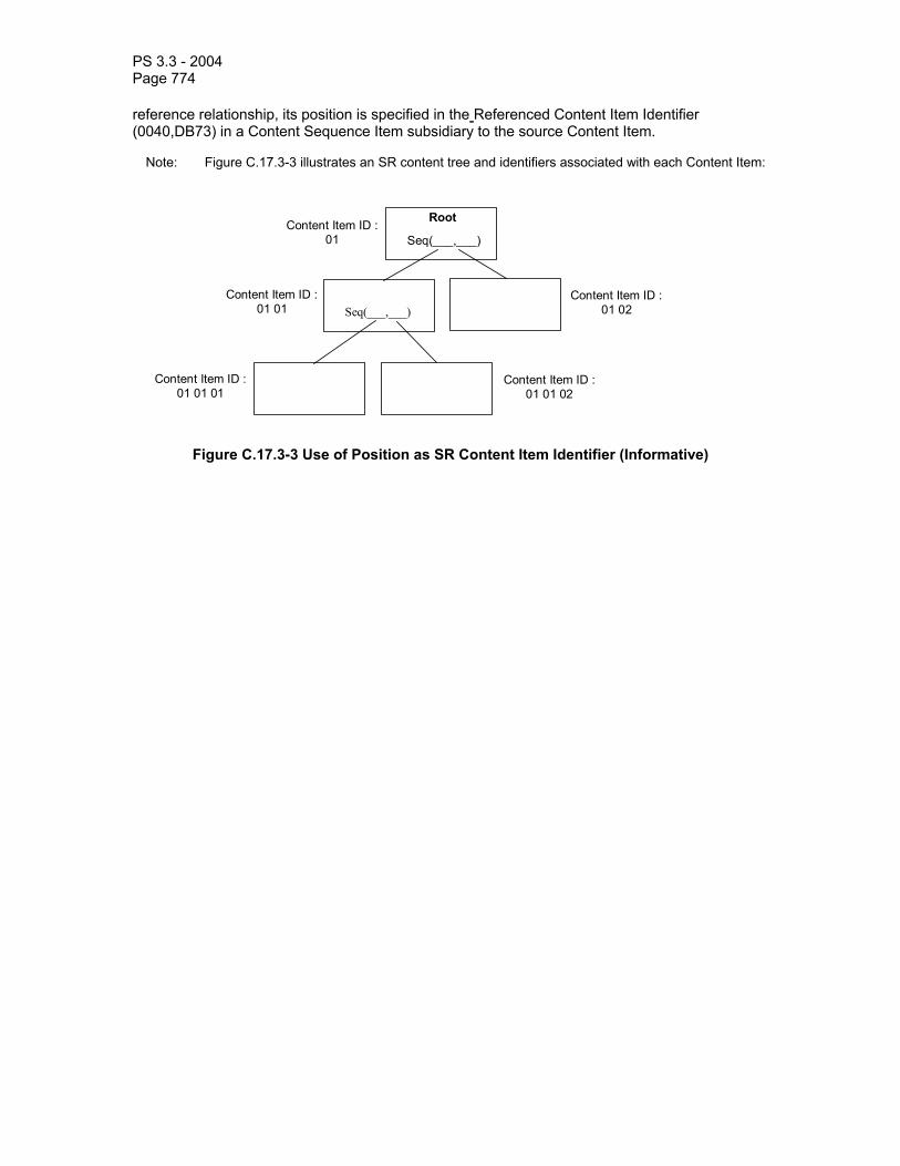
PS 3.3 - 2004 Page 774
reference relationship, its position is specified in the Referenced Content Item Identifier (0040,DB73) in a Content Sequence Item subsidiary to the source Content Item.
Note: Figure C.17.3-3 illustrates an SR content tree and identifiers associated with each Content Item:
Seq(___,___)
Seq(___,___)
Content Item ID :01
Content Item ID : 01 01
Content Item ID : 01 02
Content Item ID :01 01 01
Content Item ID :01 01 02
Root
Figure C.17.3-3 Use of Position as SR Content Item Identifier (Informative)

PS 3.3 - 2004 Page 775
C.17.4 SR Content Tree Example (Informative) Figure C.17.4-1 depicts the content of an example diagnostic interpretation.
Document Root Node CONTAINER "Chest X-ray" (Document Title)
Has obs contex t
Content Node PNAME "Recording Observer =
Smith^John^^Dr^" * Relationship Modes = By-value = By-reference
contains
contains contains
inferred from
Content Node CODE"finding = mass"
Heading Node CONTAINER "Conclusions"
Heading Node CONTAINER "Specific
Image Findings"
Content Node CODE "conclusion = probable
malignancy "
Content node SCOORD"best illustration of
findings"
Leaf Node IMAGE "Baseline"
contains contains contains
Leaf Node NUM "diameter = 1.3 cm"
Leaf Node CODE "margination = infiltrativ e"
has properties has properties
inferred from
Leaf Node IMAGE
selected from
Has obs contex t
Content Node UIDREF "Study Instance UID of
Evidence Directly Examined by RO = 1.2.3.4.5.6.7.100"
Has obs contex t
Content Node PNAME "Patient-Data-Acquisition
Subject = Homer^Jane^^^"
has concept mod Leaf Node CODE
"Views = PA and Lateral"
Notes: 1. For nodes of type CONTAINER, the contents of the Concept Name Code Sequence are shown in quotes and italicized.
2. For nodes of Value Type CODE, PNAME, NUM the contents are shown as “Concept Name Code Sequence = Value”.
3. For the nodes of Value Type IMAGE and SCOORD, the contents of the Concept Name Code Sequence indicating the purpose of reference are shown in quotes and italicized.
PS 3.3 - 2004 Page 776
4. The root node containing the Document Type is illustrated using a post-coordinated node of "Chest X-ray", qualified using a HAS CONCEPT MOD relationship by a child with a CODE meaning "Views = PA and Lateral". An alternative would be to use a single pre-coordinated code in one node that applies to the entire concept of a "Two-view (PA and Lateral) Chest X-ray". However, the use of pre-coordinated terms to describe complex concepts rapidly becomes unwieldy and difficult to search on (in the sense that more specific pre-coordinated codes do not have a visible relationship with more general codes). If it were necessary to include a longer textual description of Document Type, then this could be achieved with a HAS CONCEPT MOD relationship with one or more TEXT nodes, perhaps in different languages.
5. The Document Type is only a title, and is not being used to convey the Procedure Context, although in this example it does appear to contain a description of some aspects of Procedure Context.
Figure C.17.4-1 (Informative) SR Content Tree for an Example Diagnostic Interpretation
C.17.5 Observation Context Encoding Observation Context describes who or what is performing the interpretation, whether the examination of evidence is direct or quoted, what procedure generated the evidence that is being interpreted, and who or what is the subject of the evidence that is being interpreted.
Initial Observation Context is defined outside the SR Document Content tree by other modules in the SR IOD (i.e., Patient Module, Specimen Identification, General Study, Patient Study, SR Document Series, Frame of Reference, Synchronization, General Equipment and SR Document General modules). Observation Context defined by attributes in these modules applies to all Content Items in the SR Document Content tree and need not be explicitly coded in the tree. The initial Observation Context from outside the tree can be explicitly replaced.
If a Content Item in the SR Document Content tree has Observation Context different from the context already encoded elsewhere in the IOD, the context information applying to that Content Item shall be encoded as child nodes of the Content Item in the tree using the HAS OBS CONTEXT relationship. That is, Observation Context is a property of its parent Content Item.
The context information specified in the Observation Context child nodes (i.e. target of the HAS OBS CONTEXT relationship) adds to the Observation Context of their parent node Content item, and shall apply to all the by-value descendant nodes of that parent node regardless of the relationship type between the parent and the descendant nodes. Observation Context is encoded in the same manner as any other Content Item. See the example in Figure C.17.5-1. Observation Context shall not be inherited across by-reference relationships.
Notes: 1. For example, the “subject context” may be defined by attaching an appropriate content item to the root node with a HAS OBS CONTEXT relationship. This “subject context” then applies not only to the root node, but to all its descendants, until such time as a content item explicitly replaces the “subject context” attribute, the new value of which is then inherited by all of that nodes descendants.
2. For example, one can extend the observation context that specifies the procedure being interpreted, either from that inherited from outside the tree or from ancestors within the tree, by adding further content items that specify identifying information, such as HL7 placer and filler order numbers.
Observation DateTime is not included as part of the HAS OBS CONTEXT relationship, and therefore is not inherited along with other Observation Context. The Observation DateTime Attribute is included in each Content Item which allows different observation dates and times to be attached to different Content Items.
The IOD may specify restrictions on Content Items and Relationship Types that also constrain the flexibility with which Observation Context may be described.

PS 3.3 - 2004 Page 777
The IOD may specify Templates that offer or restrict patterns and content in Observation Context.
SR Document General Module Referenced Request Sequence>Requested Procedure ID >Requested Procedure Description
General Study Module Study Instance UID Accession Number
SR Document Content Module
Node 1
Contains
Node 2
Node C1 Node C2
Has Obs Ctx
Node 3 Node 4
Has Obs Ctx Contains Has Properties
SR Document Series Module Modality
Patient Module Patient Name Patient IDPatient Sex Patient Date Of Birth
Notes: 1. Node 2 inherits any Observation Context of Node 1, which is then extended or replaced by the
additional Observation Context defined in Nodes C1 and C2 (that is C1 and C2 are properties of 2). 2. Node 3 and its descendents inherit the Observation Context of Node 2, which includes C1 and C2. 3. Node 4 inherits the Observation Context of Node 2, which includes C1 and C2.
Figure C.17.5-1 (Informative) Definition and Inheritance of Observation Context

PS 3.3 - 2004 Page 778
C.17.6 Key Object Selection Modules C.17.6.1 Key Object Document Series Module Table C.17.6-1 defines the Attributes of the Key Object Document Series.
Note: Series of Key Object Selection Documents are separate from Series of Images or other Composite SOP Instances. Key Object Documents do not reside in a Series of Images or other Composite SOP Instances.
Table C.17.6-1
KEY OBJECT DOCUMENT SERIES MODULE ATTRIBUTES Attribute Name Tag Type Attribute Description Modality (0008,0060) 1 Modality type.
Enumerated Value: KO = Key Object Selection
Series Instance UID (0020,000E) 1 Unique identifier of the Series. Note: No specific semantics are specified.
Series Number (0020,0011) 1 A number that identifies the Series. Note: No specific semantics are specified.
Referenced Performed Procedure Step Sequence
(0008,1111) 2 Uniquely identifies the Performed Procedure Step SOP Instance for which the Series is created. Only a single Item shall be permitted in this sequence.
Notes: See notes on this attribute in Section C.17.1 SR Document Series Module
>Referenced SOP Class UID
(0008,1150) 1C Uniquely identifies the referenced SOP Class. Required if Referenced Performed Procedure Step Sequence (0008,1111) is sent.
> Referenced SOP Instance UID
(0008,1155) 1C Uniquely identifies the referenced SOP Instance. Required if Referenced Performed Procedure Step Sequence (0008,1111) is sent.
C.17.6.2 Key Object Document Module Table C.17.6-2 defines the general Attributes of a Key Object Selection Document. These Attributes identify and provide context for the Key Object Selection Document.
Table C.17.6-2 KEY OBJECT DOCUMENT MODULE ATTRIBUTES
Attribute Name Tag Type Attribute Description Instance Number (0020,0013) 1 A number that identifies the Document. Content Date (0008,0023) 1 The date the document content creation
started. Content Time (0008,0033) 1 The time the document content creation
started. Referenced Request Sequence (0040,A370) 1C Identifies Requested Procedures to which
this Document pertains. One or more Items may be included in this sequence. Required if this Document pertains to at

PS 3.3 - 2004 Page 779
least one Requested Procedure. >Study Instance UID (0020,000D) 1 Unique identifier for the Study. >Referenced Study Sequence (0008,1110) 2 Uniquely identifies the Study SOP Instance.
Only a single Item shall be permitted in this sequence.
>>Referenced SOP Class UID (0008,1150) 1 Uniquely identifies the SOP Class >>Referenced SOP Instance UID
(0008,1155) 1 Uniquely identifies the SOP Instance.
>Accession Number (0008,0050) 2 A departmental IS generated number which identifies the order for the Study.
>Placer Order Number/Imaging Service Request
(0040,2016) 2 The order number assigned to the Imaging Service Request by the party placing the order.
>Filler Order Number/Imaging Service Request
(0040,2017) 2 The order number assigned to the Imaging Service Request by the party filling the order.
>Requested Procedure ID (0040,1001) 2 Identifier of the related Requested Procedure
>Requested Procedure Description
(0032,1060) 2 Institution-generated administrative description or classification of Requested Procedure.
>Requested Procedure Code Sequence
(0032,1064) 2 A sequence that conveys the requested procedure. Zero or one Item may be included in this sequence.
>>Include 'Code Sequence Macro' Table 8.8-1 No Baseline Context ID Number is specified. Current Requested Procedure Evidence Sequence
(0040,A375) 1 List of all Composite SOP Instances referenced in the Content Sequence (0040,A730). One or more Items shall be included in this sequence.
Note: In the context of the Key Object Selection, the current evidence is considered to be only the set of instances referenced within the Key Object Selection.
>Include 'SOP Instance Reference Macro' Table C.17-3 Identical Documents Sequence (0040,A525) 1C Duplicates of this document, stored with
different SOP Instance UIDs. One or more Items may be included in this sequence. Required if this Key Object Selection document references instances in more than one Study. See C.17.2.2 and C.17.6.2.1 for further explanation and conditions.
>Include 'SOP Instance Reference Macro' Table C.17-3
C.17.6.2.1 Identical Documents If the Current Requested Procedure Evidence Sequence (0040,A375) references SOP Instances both in the current study and in one or more other studies, this document shall be duplicated into

PS 3.3 - 2004 Page 780
each of those other studies, and the duplicates shall be referenced in the Identical Documents Sequence (0040,A525).
Note: Thus a Key Object Selection Document that references images in the current study as well as in a prior or comparison study, would be duplicated into the other study. This allows an application displaying that other study to easily access notes relevant to that study's SOP Instances.
C.18 CONTENT MACROS
C.18.1 Numeric Measurement Macro Table C.18.1-1 specifies the Attributes that convey a NUM (numeric measurement) value.
Note: The Measured Value Sequence (0040,A300) may be empty to convey the concept of a measurement whose value is unknown or missing, or a measurement or calculation failure.
Table C.18.1-1
NUMERIC MEASUREMENT MACRO ATTRIBUTES Attribute Name Tag Type Attribute Description Measured Value Sequence
(0040,A300) 2 This is the value of the Content Item. Shall consist of a Sequence of Items conveying the measured value(s), which represent integers or real numbers and units of measurement. Zero or one Items shall be permitted in this sequence.
>Numeric Value (0040,A30A) 1 Numeric measurement value. Only a single value shall be present.
>Measurement Units Code Sequence
(0040,08EA) 1 Units of measurement. Only a single Item shall be permitted in this sequence.
>>Include 'Code Sequence Macro' Table 8.8-1 Defined Context ID is 82. Numeric Value Qualifier Code Sequence
(0040,A301) 3 Qualification of Numeric Value in Measured Value Sequence, or reason for absence of Measured Value Sequence Item. Only a single Item shall be permitted in this sequence.
>Include 'Code Sequence Macro' Table 8.8-1 Defined Context ID is 42.
C.18.2 Code Macro Table C.18.2-1 specifies the Attributes that convey a CODE value.
Table C.18.2-1 CODE MACRO ATTRIBUTES
Attribute Name Tag Type Attribute Description Concept Code Sequence
(0040,A168) 1 This is the value of the Content Item. Only a single Item shall be permitted in this sequence.
>Include 'Code Sequence Macro' Table 8.8-1 No Baseline Context ID is specified.
C.18.3 Composite Object Reference Macro Table C.18.3-1 specifies the Attributes that convey a reference to a DICOM Composite Object that is not a DICOM Image or Waveform (such as an SR Document).
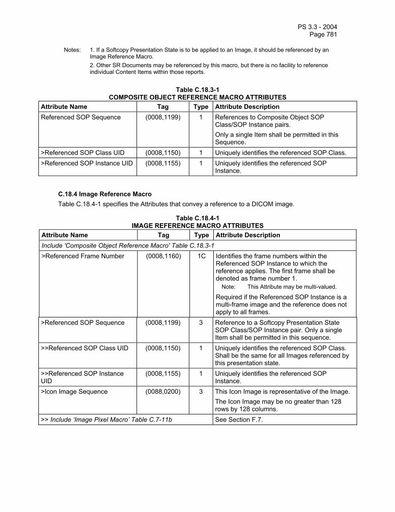
PS 3.3 - 2004 Page 781
Notes: 1. If a Softcopy Presentation State is to be applied to an Image, it should be referenced by an Image Reference Macro.
2. Other SR Documents may be referenced by this macro, but there is no facility to reference individual Content Items within those reports.
Table C.18.3-1
COMPOSITE OBJECT REFERENCE MACRO ATTRIBUTES Attribute Name Tag Type Attribute Description Referenced SOP Sequence (0008,1199) 1 References to Composite Object SOP
Class/SOP Instance pairs. Only a single Item shall be permitted in this Sequence.
>Referenced SOP Class UID (0008,1150) 1 Uniquely identifies the referenced SOP Class. >Referenced SOP Instance UID (0008,1155) 1 Uniquely identifies the referenced SOP
Instance.
C.18.4 Image Reference Macro Table C.18.4-1 specifies the Attributes that convey a reference to a DICOM image.
Table C.18.4-1 IMAGE REFERENCE MACRO ATTRIBUTES
Attribute Name Tag Type Attribute Description Include 'Composite Object Reference Macro' Table C.18.3-1 >Referenced Frame Number (0008,1160) 1C Identifies the frame numbers within the
Referenced SOP Instance to which the reference applies. The first frame shall be denoted as frame number 1.
Note: This Attribute may be multi-valued.
Required if the Referenced SOP Instance is a multi-frame image and the reference does not apply to all frames.
>Referenced SOP Sequence (0008,1199) 3 Reference to a Softcopy Presentation State SOP Class/SOP Instance pair. Only a single Item shall be permitted in this sequence.
>>Referenced SOP Class UID (0008,1150) 1 Uniquely identifies the referenced SOP Class. Shall be the same for all Images referenced by this presentation state.
>>Referenced SOP Instance UID
(0008,1155) 1 Uniquely identifies the referenced SOP Instance.
>Icon Image Sequence (0088,0200) 3 This Icon Image is representative of the Image. The Icon Image may be no greater than 128 rows by 128 columns.
>> Include ‘Image Pixel Macro’ Table C.7-11b See Section F.7.

PS 3.3 - 2004 Page 782
C.18.5 Waveform Reference Macro Table C.18.5-1 specifies the Attributes that convey a reference to a DICOM waveform.
Table C.18.5-1 WAVEFORM REFERENCE MACRO ATTRIBUTES
Attribute Name Tag Type Attribute Description Include 'Composite Object Reference Macro' Table C.18.3-1 >Referenced Waveform Channels
(0040,A0B0) 1C List of channels in Waveform to which the reference applies. See C.18.5.1.1 Required if the Referenced SOP Instance is a Waveform that contains multiple Channels and not all Channels in the Waveform are referenced.
C.18.5.1 Waveform Reference Macro Attribute Descriptions C.18.5.1.1 Referenced Waveform Channels Referenced Waveform Channels (0040,A0B0) is a multi-value attribute which lists the channels referenced. Each channel is specified as a pair of values (M,C), where the first value is the sequence item number of the Waveform Sequence (5400,0100) attribute in the referenced object (i.e. the Multiplex Group Number), and the second value is the sequence item number of the Channel Definition Sequence (003A,0200) attribute (i.e., the Channel Number) within the multiplex group.
If the specified channel number is 0, the annotation applies to all channels in the multiplex group.
Note: As an example, an annotation which applies to the entire first multiplex group and channels 2 and 3 of the third multiplex group would have Referenced Waveform Channels (0040,A0B0) value 0001 0000 0003 0002 0003 0003.
C.18.6 Spatial Coordinates Macro Table C.18.6-1 specifies the Attributes that conveySpatial Coordinates in an SCOORD Content Item. An SCOORD Content Item shall always be the Source Content Item of one or more SELECTED FROM Relationships with IMAGE Target Content Items. Each IMAGE Target Content Item shall contain a reference to one single frame or multi-frame Image.
Note: The same set of spatial coordinates may be selected from more than one single-frame image, or more than one frame of a multi-frame image when the purpose of reference is applicable to multiple images. For example, the spatial coordinates may specify the outline of a sampling region at the same spatial location on multiple images acquired over time.
Table C.18.6-1
SPATIAL COORDINATES MACRO ATTRIBUTES Attribute Name Tag Type Attribute Description Graphic Data (0070,0022) 1 An ordered set of (column,row) pairs that
denote positions in an image specified with sub-pixel resolution such that the origin at the TLHC of the TLHC pixel is 0.0\0.0, the BRHC of the TLHC pixel is 1.0\1.0, and the BRHC of the BRHC pixel is Columns\Rows. The values must be within the range 0\0 to Columns\Rows. The values Columns

PS 3.3 - 2004 Page 783
(0028,0011) and Rows (0028,0010) are those contained in the referenced image. See C.18.6.1.1 for further explanation.
Graphic Type (0070,0023) 1 See C.18.6.1.2 for Enumerated Values.
C.18.6.1 Spatial Coordinates Macro Attribute Descriptions C.18.6.1.1 Graphic Data Graphic Data may be used to associate an anatomic or spatial Concept with a defined subset of one or more images. Graphic Data may be explicitly defined as a single point (i.e. to denote the epicenter of an anatomic site or lesion) or more than one point (i.e. representing a set of points or an open or closed polygon).
Note: Spatial coordinates may be used to associate observational data with a set of Image features. Spatial coordinates also may be used to convey coordinates that are input data for a measurement.
C.18.6.1.2 Graphic Type When annotation applies to an image, this attribute defines the type of geometry of the annotated region of interest. The following Enumerated Values are specified for image spatial coordinate geometries:
POINT = a single pixel denoted by a single (column,row) pair MULTIPOINT = multiple pixels each denoted by an (column,row) pair POLYLINE = a series of connected line segments with ordered vertices denoted by
(column,row) pairs; if the first and last vertices are the same it is a closed polygon CIRCLE = a circle defined by two (column,row) pairs. The first point is the central pixel. The
second point is a pixel on the perimeter of the circle. ELLIPSE = an ellipse defined by four pixel (column,row) pairs, the first two points
specifying the endpoints of the major axis and the second two points specifying the endpoints of the minor axis of an ellipse
C.18.7 Temporal Coordinates Macro Table C.18.7-1 specifies the Attributes that convey TCOORD Content Items. A TCOORD Content Item shall be the Source Content Item of one or more SELECTED FROM relationships with one or more SCOORD Content Items, one or more IMAGE Content Items, or one or more WAVEFORM Content Items.
Notes: 1. The same set of temporal coordinates may be selected from more than one single-frame image, or more than one frame of a multi-frame image, or from images and waveforms when the purpose of reference is applicable to multiple objects. For example, the definition of a sampling period at different spatial locations on multiple images and a synchronously acquired waveform.
2. Temporal coordinates may refer to spatial coordinates which in turn refer to one or more frames or images, for example to indicate a region localized in both time and space.

PS 3.3 - 2004 Page 784
Table C.18.7-1 TEMPORAL COORDINATES MACRO ATTRIBUTES
Attribute Name Tag Type Attribute Description Temporal Range Type (0040,A130) 1 See C.18.7.1.1 for Enumerated Values. Referenced Sample Positions (0040,A132) 1C List of samples within a multiplex group
specifying temporal points of the referenced data. Position of first sample is 1. Required if the Referenced SOP Instance is a Waveform and Referenced Time Offsets (0040,A138) and Referenced Datetime (0040,A13A) are not present. May be used only if Referenced Channels (0040,A0B0) refers to channels within a single multiplex group.
Referenced Time Offsets (0040,A138) 1C Specifies temporal points for reference by number of seconds after start of data. Required if Referenced Sample Positions (0040,A132) and Referenced Datetime (0040,A13A) are not present.
Referenced Datetime (0040,A13A) 1C Specifies temporal points for reference by absolute time. Required if Referenced Sample Positions (0040,A132) and Referenced Time Offsets (0040,A138) are not present.
C.18.7.1 Temporal Coordinates Macro Attribute Descriptions C.18.7.1.1 Temporal Range Type This Attribute defines the type of temporal extent of the region of interest. A temporal point (or instant of time) may be defined by a waveform sample offset (for a single waveform multiplex group only), time offset, or absolute time.
The following Enumerated Values are specified for Temporal Range Type:
POINT = a single temporal point MULTIPOINT = multiple temporal points SEGMENT = a range between two temporal points MULTISEGMENT = multiple segments, each denoted by two temporal points BEGIN = a range beginning at one temporal point, and extending beyond the end of the
acquired data END = a range beginning before the start of the acquired data, and extending to (and
including) the identified temporal point
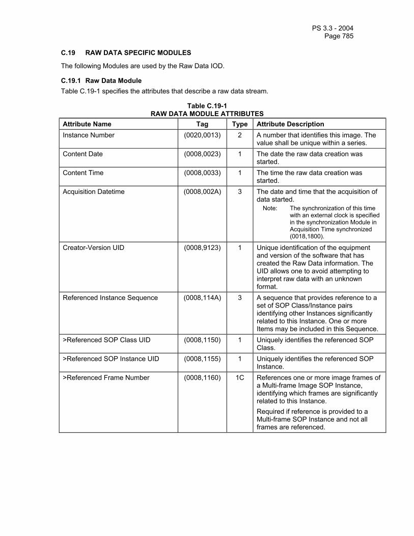
PS 3.3 - 2004 Page 785
C.19 RAW DATA SPECIFIC MODULES
The following Modules are used by the Raw Data IOD.
C.19.1 Raw Data Module Table C.19-1 specifies the attributes that describe a raw data stream.
Table C.19-1 RAW DATA MODULE ATTRIBUTES
Attribute Name Tag Type Attribute Description Instance Number (0020,0013) 2 A number that identifies this image. The
value shall be unique within a series. Content Date (0008,0023) 1 The date the raw data creation was
started. Content Time (0008,0033) 1 The time the raw data creation was
started. Acquisition Datetime (0008,002A) 3 The date and time that the acquisition of
data started. Note: The synchronization of this time
with an external clock is specified in the synchronization Module in Acquisition Time synchronized (0018,1800).
Creator-Version UID (0008,9123) 1 Unique identification of the equipment and version of the software that has created the Raw Data information. The UID allows one to avoid attempting to interpret raw data with an unknown format.
Referenced Instance Sequence (0008,114A) 3 A sequence that provides reference to a set of SOP Class/Instance pairs identifying other Instances significantly related to this Instance. One or more Items may be included in this Sequence.
>Referenced SOP Class UID (0008,1150) 1 Uniquely identifies the referenced SOP Class.
>Referenced SOP Instance UID (0008,1155) 1 Uniquely identifies the referenced SOP Instance.
>Referenced Frame Number (0008,1160) 1C References one or more image frames of a Multi-frame Image SOP Instance, identifying which frames are significantly related to this Instance. Required if reference is provided to a Multi-frame SOP Instance and not all frames are referenced.

PS 3.3 - 2004 Page 786
>Purpose of Reference Code Sequence
(0040,A170) 1 Describes the purpose for which the reference is made. Only a single Item shall be permitted in this sequence. See C.7.6.16.2.5.1.
>>Include ‘Code Sequence Macro’ Table 8.8-1 No Baseline Context ID is defined. Include any private attributes that contain Raw Data information. See section C.19.1.1 for further explanation. C.19.1.1 Raw Data The Raw Data stored with the Raw Data Module consists of one or more private attributes that are vendor specific. No rules are specified about the content and format of the raw data.
C.20 SPATIAL REGISTRATION
C.20.1 Spatial Registration Series Module Table C.20.1-1 defines the general Attributes of the Spatial Registration Series Module.
Table C.20.1-1 SPATIAL REGISTRATION SERIES MODULE ATTRIBUTES
Attribute Name Tag Type Attribute Description Modality (0008,0060) 1 Modality type.
Enumerated Value: REG
C.20.2 Spatial Registration Module Table C.20.2-1 defines the general Attributes of the Spatial Registration Module.
Table C.20.2-1 SPATIAL REGISTRATION MODULE ATTRIBUTES
Attribute Name Tag Type Attribute Description Content Date (0008,0023) 1 The date the content creation started. Content Time (0008,0033) 1 The time the content creation started. Instance Number (0020,0013) 1 A number that identifies this instance Content Label (0070,0080) 1 A label that is used to identify this
registration. Content Description (0070,0081) 2 A description of this registration. Content Creator’s Name (0070,0084) 2 Name of operator performing the
registration (such as a technologist or physician).
Registration Sequence (0070,0308) 1 A sequence of one or more registration items. Each item defines a spatial registration to the referenced images in that item. All referenced images are in the same spatial frame of reference or atlas.
>Frame of Reference UID (0020,0052) 1C Identifies a Frame of Reference that may or may not be an image set (e.g. atlas or physical space). See C.7.4.1.1.1 for further

PS 3.3 - 2004 Page 787
explanation. Required if Referenced Image Sequence (0008,1140) is absent. May be present otherwise.
>Referenced Image Sequence (0008,1140) 1C Identifies the set of images registered in this sequence item. One or more items shall be present. Required if Frame of Reference UID (0020,0052) is absent. May be present otherwise.
>>Include 'Image SOP Instance Reference Macro' Table 10-3 >Matrix Registration Sequence (0070,0309) 1 A sequence that specifies one spatial
registration. Exactly one item shall be present
>>Frame of Reference Transformation Comment
(3006,00C8) 3 User description or comments about the registration.
>>Registration Type Code Sequence
(0070,030D) 2 Describes the information input into the registration process. Only one item may be present.
>>>Include ‘Code Sequence Macro’ Table 8.8-1 Baseline Context ID is 7100 >>Matrix Sequence (0070,030A) 1 One or more items shall be present. Each
item specifies a transformation. The item order is significant and corresponds to matrix multiplication order. See C.20.2.1.1.
>>>Frame of Reference Transformation Matrix
(3006,00C6) 1 A 4x4 homogeneous transformation matrix that registers the referenced images to the local RCS. Matrix elements shall be listed in row-major order. See C.20.2.1.1.
>>>Frame of Reference Transformation Matrix Type
(0070,030C) 1 Type of Frame of Reference Transformation Matrix (3006,00C6). Defined terms: RIGID RIGID_ SCALE AFFINE See C.20.2.1.2
>Used Fiducials Sequence (0070,0314) 3 The fiducials used to determine the Frame of Reference Transformation Matrix. One or more Items may be present.
>>Fiducial UID (0070,031A) 1 The UID that identifies the fiducial used as registration input.
C.20.2.1 Registration Module Attribute Descriptions C.20.2.1.1 Frame of Reference Transformation Matrix The Frame of Reference Transformation Matrix (3006,00C6) AMB describes how to transform a point (Bx,By,Bz) with respect to RCSB into (Ax,Ay,Az) with respect to RCSA according to the equation below.

PS 3.3 - 2004 Page 788
=
110001
B
B
B
333231
232221
131211
A
A
A
zyx
TMMMTMMMTMMM
zyx
z
y
x
The Frame of Reference Transformation Matrix is expressible as multiple matrices, each in a separate item of the Matrix Sequence (0070,030A). The equation below specifies the order of the matrix multiplication where M1, M2 and M3 are the first, second and third items in the sequence.
[ ] [ ]( )( )TT zyxzyx 11''' 123 MMM=
where [ ]Tzyx 1 =
1zyx
Registration often involves two or more RCS, each with a corresponding Frame of Reference Transformation Matrix. For example, another Frame of Reference Transformation Matrix AMC can describe how to transform a point (Cx,Cy,Cz) with respect to RCSC into (Ax,Ay,Az) with respect to RCSA. It is straightforward to find the Frame of Reference Transformation Matrix BMC that describes how to transform the point (Cx,Cy,Cz) with respect to RCSC into the point (Bx,By,Bz) with respect to RCSB. The solution is to invert AMB and multiply by AMC, as shown below:
∗=
−
1
)(
1
1
zyx
zyx
C
C
C
CA
BA
B
B
B
MΜ
C.20.2.1.2 Frame of Reference Transformation Matrix Type There are three types of Registration Matrices:
RIGID: This is a registration involving only translations and rotations. Mathematically, the matrix is constrained to be orthonormal and describes six degrees of freedom: three translations, and three rotatations.
RIGID_SCALE: This is a registration involving only translations, rotations and scaling. Mathematically, the matrix is constrained to be orthogonal and describes nine degrees of freedom: three translations, three rotations and three scales. This type of transformation is sometimes used in atlas mapping.
AFFINE: This is a registration involving translations, rotations, scaling and shearing. Mathematically, there are no constraints on the elements of the Frame of Reference Transformation Matrix, so it conveys twelve degrees of freedom. This type of transformation is sometimes used in atlas mapping.
See the PS 3.17 Annex on Transforms and Mappings for more detail.

PS 3.3 - 2004 Page 789
C.21 SPATIAL FIDUCIALS
C.21.1 Spatial Fiducials Series Module Table C.21.1-1 defines the general Attributes of the Spatial Fiducials Series Module.
Table C.21.1-1 SPATIAL FIDUCIALS SERIES MODULE ATTRIBUTES
Attribute Name Tag Type Attribute Description Modality (0008,0060) 1 Modality type.
Enumerated Value: FID
C.21.2 Spatial Fiducials Module Table C.21.2-1 defines the general Attributes of the Registration.
Table C.21.2-1 SPATIAL FIDUCIALS MODULE ATTRIBUTES
Attribute Name Tag Type Attribute Description Content Date (0008,0023) 1 The date the content creation started. Content Time (0008,0033) 1 The time the content creation started. Instance Number (0020,0013) 1 A number that identifies this instance Content Label (0070,0080) 1 A label that is used to identify this
registration. Content Description (0070,0081) 2 A description of this registration. Content Creator’s Name (0070,0084) 2 Name of operator performing the
registration (such as a technologist or physician).
Fiducial Set Sequence (0070,031C) 1 A sequence of one or more items, each of which is a fiducial set.
>Frame of Reference UID (0020,0052) 1C Identifies a Frame of Reference that may or may not be an image set (e.g. an atlas or physical space). See C.7.4.1.1.1 for further explanation. Required if Referenced Image Sequence (0008,1140) is absent. May be present otherwise.
>Referenced Image Sequence (0008,1140) 1C Identifies the set of images in which the fiducials are located. Required if Frame of Reference UID (0020,0052) is absent. May be present otherwise. One or more Items shall be present. All referenced images shall have the same Frame of Reference UID if present in the images.
>>Include 'Image SOP Instance Reference Macro' Table 10-3 >Fiducial Sequence (0070,031E) 1 A sequence that specifies one or more
fiducials, one item per fiducial. >>Fiducial Identifier (0070,0310) 1 A fiducial assignment identifier that is
unique within this Fiducial Sequence item

PS 3.3 - 2004 Page 790
but may match the fiducial identifier of an equivalent feature in another item.
>>Fiducial Identifier Code Sequence
(0070,0311) 1C A code sequence for a term that identifies a well-known fiducial type (potentially including methodology, anatomy, tools, etc.). Only one item shall be present. Required if Identifier (0070,0310) is absent. May be present otherwise.
>>>Include ‘Code Sequence Macro’ Table 8.8-1 DCID 7101 >>Fiducial UID (0070,031A) 3 Globally unique identifier for the fiducial
instance of this fiducial assignment. >>Fiducial Description (0070,030F) 3 User description or comments about the
fiducial. >>Shape Type (0070,0306) 1 See C.21.2.1.1 for defined terms. >>Number of Contour Points (3006,0046) 1C Number of points (triplets) in Contour Data
(3006,0050). Required if Contour Data is present.
>>Contour Data (3006,0050) 1C Specifies the coordinates of this item's fiducial. One triplet (x,y,z) shall be present for each point in the fiducial. See C.21.2.1.2 for further explanation. Required if Frame of Reference UID (0020,0052) is present in this item of the Fiducial Set Sequence (0070,031C). Shall not be present otherwise.
>>Contour Uncertainty Radius (0070,0312) 3 The estimated uncertainty radius for the Contour Data in mm. See C.21.2.1.3
>>Graphic Coordinates Data Sequence
(0070,0318) 1C The image pixel locations of the fiducial’s points. Shall contain one or more items. More than one item shall be present only if a fiducial spans more than one image. Required if Contour Data is not present. May be present otherwise.
>>>Graphic Data (0070,0022) 1 Graphic point coordinates of the fiducial points in the image of the Referenced Image Sequence. The points correlate to Fiducial’s Contour Data (3006,0050), if present, one row-column pair for each point and in the same order. See C.10.5.1.2 for further explanation.
>>>Referenced Image Sequence (0008,1140) 1 A sequence that specifies the image containing the fiducial’s graphic coordinates. Only one item shall be present. Shall be an image within the set of the images in the Referenced Image Sequence (0008,1140) of the encapsulating Fiducial Set Sequence (0070,031C) item.
>>>>Include 'Image SOP Instance Reference Macro' Table 10-3

PS 3.3 - 2004 Page 791
C.21.2.1 Spatial Fiducials Module Attribute Descriptions C.21.2.1.1 Shape Type For convenient registration, correlated Fiducials exist in each image set of the Registration Sequence. Correlated Fiducials are identified with either Fiducial Identifier (0070,0310) or Fiducial Identifier Code Sequence (0070,0311). Shape Type (0070,0306) defines the geometric interpretation of the Contour Data (3006,0050). Defined Terms are:
POINT = a single triplet (x,y,z) designating a single fiducial point. Note: A point may be the epicenter of a more complex shape such as sphere.
LINE = two points that specify a line or axis such as the inter-orbital line. The point locations have no significance other than identifying the line, i.e. they are not line segment end points.
PLANE = three points that identify a plane such as the laterality plane SURFACE = three or more points (usually many) that reside on, or near, a region of a
curved surface. The surface may be flat or curved, closed or open. The point order has no significance.
RULER = two or more evenly spaced collinear points ordered sequentially along the line, such as a physical ruler placed in the imaging field.
L-SHAPE = three points of two perpendicular line segments, AB and BC, having a common end point B. The order of the points is: ABC. May represent an L-shaped marker placed in the imaging field.
T-SHAPE = three points of two perpendicular line segments AB and CD, such that C bisects AB. The order is ABD.
SHAPE = three or more points that specify the shape of a well-known fiducial type. The term in the Fiducial Identifier Code Sequence (0070,0311) defines the shape and the order of the points that represent it.
C.21.2.1.2 Contour Data
Contour Data (3006,0050) is an ordered set of triplets that defines a shape. The triplets (x,y,z) denote points in the Reference Coordinate System of the Registration Instance.
Note: Contours may associate observational data with a set of Image features or specify coordinates that are input data for a measurement.
C.21.2.1.3 Contour Uncertainty Radius The uncertainty is an estimate of the standard deviation of the fiducial location process.
C.22 MEDIA CREATION MANAGEMENT SPECIFIC MODULES
The following Sections specify Modules used for Media Creation Management.
C.22.1 Media Creation Management Module Table C.22.1-1
MEDIA CREATION MANAGEMENT MODULE ATTRIBUTES Attribute name Tag Attribute Description Storage Media File-Set ID (0088,0130) User or implementation specific human readable
identification of the Storage Media to be created. Storage Media File-Set UID (0088,0140) Uniquely identifies a Storage Media to be created. Number of Copies (2000,0010) Number of copies of set of media to be created for
storing this file-set. Note: If the entire request fits on a single piece of

PS 3.3 - 2004 Page 792
media per copy, then this value corresponds to the actual number of pieces of media to be created.
Request Priority (2200,0020) Specifies the priority of the request. Enumerated Values: HIGH MED LOW
Label Using Information Extracted From Instances
(2200,0001) Specifies whether or not to extract label information from the instances. Enumerated Values: YES NO
Label Text (2200,0002) Unformatted free text to include in the label instead of or in addition to information extracted from the instances.
Label Style Selection (2200,0003) An implementation-dependent code string that may be used as a hint to select a particular layout or format of label.
Media Disposition (2200,0004) Unstructured text that describes where and to whom the media is to be sent.
Barcode Value (2200,0005) String that describes the bar code value to be printed on the media label.
Note It is SCU responsibility to convey a value for this attribute coherent in length and content with the requested Barcode Symbology (2200,0006).
Barcode Symbology (2200,0006) Code string that describes the bar code symbology that shall be used for printing the Barcode Value (2200,0005). See Section C.22.1.1 for Defined Terms.
Allow Media Splitting (2200,0007) A flag indicating if the SCP is allowed to split this request over more than one piece of media. Enumerated Values: YES NO
Note: 1. The SCP is not required to support the split
of a media creation request across more than one piece of media.
2. If the size of the set of SOP instances is greater than the media storage capacity, and this flag has been set to NO, the SCP shall refuse to process the request.
Allow Lossy Compression (2200,000F) A flag indicating if the SCP is allowed to perform lossy compression. Enumerated Values:
YES NO

PS 3.3 - 2004 Page 793
Include Non-DICOM Objects (2200,0008) A flag indicating if the SCP should include in the media additional Non-DICOM information/objects Defined Terms: NO FOR_PHYSICIAN FOR_PATIENT FOR_TEACHING FOR_RESEARCH
Include Display Application (2200,0009) A flag indicating if the SCP should include on the media a DICOM Instance Display Application. Enumerated Values: NO YES
Preserve Composite Instances After Media Creation
(2200,000A) A flag to indicate whether or not the SCU intends to issue a subsequent media creation request referencing some or all of the instances contained in Referenced SOP Sequence (0008,1199). Enumerated Values: YES NO
Referenced SOP Sequence (0008,1199) A sequence of repeating Items where each Item references a single SOP Instance, the Media Application Profile to be used, and, where applicable, the icon representing the referenced image
>Referenced SOP Class UID (0008,1150) Uniquely identifies the referenced SOP Class. >Referenced SOP Instance UID (0008,1155) Uniquely identifies the referenced SOP Instance. >Requested Media Application Profile (2200,000C) The Media Application Profile to be used for this
SOP Instance. Note: This is the label of the profile as defined in PS
3.11, e.g. “STD-XABC-CD”.
>Icon Image Sequence (0088,0200) This Icon Image is representative of the Image. >> Include ‘Image Pixel Macro’ Table C.7-11.2 Execution Status (2100,0020) Execution status of a request.
See Section C.22.1.2 for Enumerated Values Execution Status Info (2100,0030) Additional information about Execution Status
(2100,0020). When Execution Status is DONE, CREATING or IDLE, Defined Terms are:
NORMAL See Section C.22.1.3 for Defined Terms when the Execution Status is PENDING or FAILURE.
Total Number of Pieces of Media Created
(2200,000B) Number of pieces of media that have been successfully created, in order to store all copies of the requested file-set.
Note: If the entire request fits on a single piece of

PS 3.3 - 2004 Page 794
media per copy, then this value corresponds to the number of copies of media created.
Failed SOP Sequence (0008,1198) A sequence of repeating Items describing SOP Instances for which media creation failed.
>Referenced SOP Class UID (0008,1150) Uniquely identifies the referenced SOP Class. >Referenced SOP Instance UID (0008,1155) Uniquely identifies the referenced SOP Instance. >Requested Media Application Profile (2200,000C) The Media Application Profile used for this SOP
Instance. Note: This is the label of the profile as defined in PS
3.11, e.g. “STD-XABC-CD”.
>Failure Reason (0008,1197) The reason that media creation failed for this SOP Instance. See Section C.22.1.4.
>Failure Attributes (2200,000E) Attributes associated with the Failure Reason (0008,1197). See Section C.22.1.4.
Referenced Storage Media Sequence (2200,000D) A Sequence describing the identifiers of all pieces of media created to satisfy the request. One or more items are allowed.
Note: If the SCP splits a media creation request across more than one piece of media (e.g. if it doesn’t fit on one), then all the created pieces of media will be included in this Sequence.
> Storage Media File-Set ID (0088,0130) User or implementation specific human readable identification of the Storage Media that has been created.
> Storage Media File-Set UID (0088,0140) Uniquely identifies the Storage Media that has been created.
C.22.1.1 Barcode Symbology Defined Terms for Barcode Symbology (2200,0006) are:
CODE128 Code 128. ISO/IEC 15417:2000 Information technology – Automatic identification and data capture techniques – Bar code symbology specification – Code128
CODE39 Code 39. ISO/IEC 16388:1999 Information technology – Automatic identification and data capture techniques – Bar code symbology specifications – Code 39
INTER_2_5 Interleaved 2 of 5. (also known as USS ITF 2/5, I-2/5, ITF 2of5) ISO/IEC 16390:1999 Information technology – Automatic identification and data capture techniques – Bar code symbology specifications – Interleaved 2 of 5
HIBC ANSI/HIBC 1-1996 Health Industry Bar Code (HIBC) Provider Applications Standard
Note This table doesn’t suppose to list all the bar code symbologies in use (there are currently more than 400). Implementations supporting other symbologies can extend this list. Implementation specific code values shall be defined in the Conformance Statement.

PS 3.3 - 2004 Page 795
C.22.1.2 Execution Status Enumerated Values for Execution Status (2100,0020) are:
IDLE The SCP has created the media creation management instance, but it has not been yet scheduled.
Note It describes the status of a new media creation management instance (N-CREATE operation performed) for which the N-ACTION action has not been yet issued.
PENDING This media creation management instance is still scheduled for processing.
CREATING This media creation management instance is being processed. DONE This media creation management instance has been
successfully processed. FAILURE This media creation management instance failed to be
processed.
C.22.1.3 Execution Status Info Defined Terms for Execution Status Info (2100,0030) are:
CHECK_MCD_OP The media creation request could not be accomplished since the device is not ready at this time and needs to be checked by an operator (e.g., covers/doors opened or device jammed).
CHECK_MCD_SRV The media creation request could not be accomplished since the device is not ready at this time and needs to be checked by a vendor service engineer (e.g., internal component failure).
DIR_PROC_ERR The DICOMDIR building process failed for some unspecified reason (e.g., mandatory attributes or values missing).
DUPL_REF_INST Duplicated instances in the Referenced SOP Sequence (0008,1199).
INST_AP_CONFLICT One or more of the elements in the Referenced SOP Sequence (0008,1199) are in conflict (e.g., the SOP Class specified is not consistent with the requested Application Profile).
INST_OVERSIZED A single instance size exceeds the actual media capacity. Note: DICOM media does not support spanning of instances
across volumes.
INSUFFIC_MEMORY There is not enough memory available to complete this request. MCD_BUSY Media creation device is not available at this time, but should
become ready without user intervention (e.g the media creation device‘s buffer capacity is full). The SCU should retry later.
MCD_FAILURE Media creation device fails to operate. This may depend on permanent or transient hardware failures (e.g robot arm broken, DVD writer failed) or because it has been disabled by an operator.
NO_INSTANCE One or more of the SOP Instances in the Referenced SOP Sequence (0008,1199) are not available.

PS 3.3 - 2004 Page 796
NOT_SUPPORTED One or more of the Application Profiles, and/or SOP Classes, referenced in the Referenced SOP Sequence (0008,1199) are not supported by the SCP.
OUT_OF_SUPPLIES No more supplies (e.g., blank media, labeling ink) are available for the media creation device. Operator intervention is required to replenish the supply.
Note This service is not supposed to provide detailed device status information, however sophisticated media creating devices can extend this table to return more information about the supply to be replenished. Implementation specific code values shall be defined in the Conformance Statement.
PROC_FAILURE A general processing failure was encountered. QUEUED This Media Creation Management instance is still in queue SET_OVERSIZED The file-set size exceeds the actual media capacity, and the
device is not capable of splitting across multiple pieces of media.
UNKNOWN There is an unspecified problem
Note: For most of the above statuses, the SCU can obtain more details about the processing errors (e.g., what are the SOP instances not available) by using the Failure Reason Attribute (0008,1197) within the Failed SOP Sequence (0008,1198).
C.22.1.4 Failure Reason Defined Terms for Failure Reason (0008,1197) are:
Code Further meaning Description 0110H Processing failure A general failure in processing the operation was
encountered. 0112H No such object
instance One or more of the instances listed in the Referenced SOP Sequence (0008,1199) was not available.
0122H Referenced SOP Class not supported
A media creation has been requested for a SOP Instance with a SOP Class that is not supported by the SCP.
0119H Class/Instance conflict The SOP Class of an instance in the Referenced SOP Instance Sequence did not correspond to the SOP class of the SOP Instance stored at the SCP.
0201H Media Application Profiles conflict
One or more of the Media Application Profiles referenced in the Reference SOP Sequence (0008,1199) are in conflict (e.g. for the same request a STD-GEN-CD and a STD-GEN-DVD is referenced).
0202H Media Application Profile / Instance conflict
The SOP Class of an instance in the Referenced SOP Sequence (0008,1199) did not correspond to a SOP class permitted for the requested or supported Media Application Profiles.
0203H Media Application Profile / Compression conflict
The profile for an instance in the Referenced SOP Sequence (0008,1199) specified lossy compression but Allow Lossy Compression (2200,000F) has a value of NO.

PS 3.3 - 2004 Page 797
0204H Media Application Profile not supported
Media creation has been requested for an Application Profile that is not supported by the SCP.
0205H Instance size exceeded
A single instance size exceeds the actual media capacity.
Note: DICOM media does not support spanning of instances across volumes.
0120H Missing attribute A required Attribute (e.g., Patient ID) was not supplied. The missing Attribute(s) shall be listed in Failure Attributes (2200,000E).
0121H Missing attribute value A required Attribute Value (e.g., the Content Date for a Structured Report) was not supplied. The Attribute(s) with missing values shall be listed in Failure Attributes (2200,000E).

PS 3.3 - 2004 Page 798
Annex D Codes and Controlled Terminology (Informative)
Retired. See PS 3.16.

PS 3.3 - 2004 Page 799

PS 3.3 - 2004 Page 800
Annex E Explanation of patient orientation (Normative)
Move to PS 3.17.

PS 3.3 - 2004 Page 801

PS 3.3 - 2004 Page 802
Annex F Basic Directory Information Object Definition (Normative)
F.1 SCOPE OF THE BASIC DIRECTORY INFORMATION IOD
The Basic Directory Information Object Definition may be used for DICOM Media Storage (See PS 3.10) and the Media Storage Service Class (See PS 3.4). It is an abstraction of the information to:
a. Identify a File-set b. Provide a directory which facilitates access to the information stored in the files of a
File-set based on key medical information. Such a directory facility relies on a hierarchical information model of medical summary information referencing the content of the Files stored in a File-set on a storage medium. Standardizing such a directory function is a key element to facilitate the interchange of medical imaging data and is intended to support the complete range of modality imaging information.
Note: The directory information has been defined so that a future version of this Part may be extended to support the distribution of the directory information among a logical tree of several files (with the DICOMDIR file at its root). However in this version of this Part, the entire directory information is specified to be stored in a single File with a DICOMDIR File ID.
Other DICOM File-setsmay be present
File ID = DICOMDIR
File-set information +Medical Info. Directory
DICOM File-set
Formatted Physical Medium
File ID = AB\CDE\FG
File ID = AB\CDE\FH
File ID = ABGT
File ID = AB\CDE\FI
File ID = AB\18
File ID = AB/12
Figure F.1-1 THE DICOMDIR FILE. A CENTRAL ROLE IN A DICOM FILE-SET
Notes: 1. Whether a single File-set or multiple File-sets are allowed on a formatted Physical Media is defined by the Media Format specification (used for each specific Physical Media) in PS 3.12.
2. The DICOMDIR File is identified by a single component File ID, DICOMDIR. Other files in the File-set may have File IDs made of a single component (e.g. "ABGT" in the figure above) or multiple components (e.g. AB\12 or AB\CDE\FI) not to exceed 8 components (See PS 3.10).
This Basic Directory Information Object:
a. is based on a structure of basic medical information. It is not a file system directory such as the one which may be used by the Media Format Layer;
b. is simple enough to meet the requirements of elementary Media Interchange applications;

PS 3.3 - 2004 Page 803
c. is efficient in supporting update to the directory on rewritable media without a complete rewrite of the entire DICOMDIR File;
d. is extendible for specific applications with specialized selection keys in addition to the standard keys;
e. does not mandate any relationship between the hierarchy of the medical information in the DICOM Directory and the hierarchy of the File ID Components;
Note: Such an independence between the structure of the file identifiers, from which no semantical
information shall be inferred, and the DICOM Directory which conveys medical imaging information, ensures that the broadest inter-operability is possible between conforming DICOM media storage implementations.
F.2 BASIC DIRECTORY IOD OVERVIEW
The general organization of the Basic Directory IOD is introduced in this Section. A simple example is also provided to illustrate the application of this organization.
F.2.1 Basic directory IOD organization The Basic Directory IOD organization is based on a hierarchy of Directory Entities. At the origin of this inverted tree is a root Directory Entity. Each Directory Entity includes one or more Directory Records which in turn, may each reference a lower level Directory Entity.
Directory Records serve to reference objects stored in the Files of the File-set. The organization of the Directory is depicted by the Basic Directory IOD entity/relationship model presented in Figure F.2-1.
Each Directory Record, irrespective of the Directory Entity it is included in, contains four types of information:
a. A reference to a lower level Directory Entity or Referenced Directory Entity. This reference may be absent if such a lower level Directory Entity does not exist for an instance of a directory record;
b. A reference to a File of the File-set in which is stored a "Referenced Object" (formally called in DICOM a Referenced SOP Instance). This reference may be absent if no File is referenced. Files may be referenced either directly by their File ID or indirectly through a Multi-Referenced File Directory Record. The latter case allows the same File to be referenced by several Directory Records;
c. A set of "selection keys," specific to a Referenced Object, which will allow its selection among all the records included in a given Directory Entity;
d. A mechanism to chain the various Directory Records which belong to the same Directory Entity.
This generic content of a Directory Record is further specialized based on its specific type in the context the Basic Directory IOD Information Model specified in Section F.4 (e.g., a Study Record, a Series Record, etc.). A Directory Entity may include Directory Records of different Types. By standardizing a number of specific Directory Records (see Section F.5) in the context of the Basic Directory IOD Information Model, one allows the definition of a variety of directory contents while maintaining a framework for interoperability.
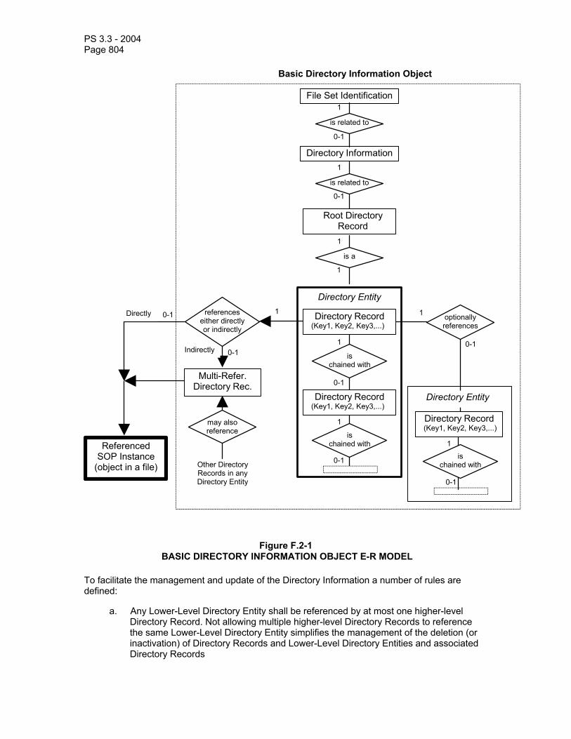
PS 3.3 - 2004 Page 804
File Set Identification
Directory Information
is related to
is related to
1
0-1
0-1
0-1
1 1
1
1
0-1
0-1
0-1
0-1
1
may also reference
Referenced SOP Instance
(object in a file)
Multi-Refer. Directory Rec.
Other DirectoryRecords in anyDirectory Entity
Directly
Indirectly
references either directly or indirectly
optionally references
Directory Record (Key1, Key2, Key3,...)
1
0-1
Basic Directory Information Object
Directory Record (Key1, Key2, Key3,...)
Directory Record (Key1, Key2, Key3,...)
is chained with
is chained with
is chained with
Directory Entity
Directory Entity
Root Directory Record
is a
1
1
Figure F.2-1 BASIC DIRECTORY INFORMATION OBJECT E-R MODEL
To facilitate the management and update of the Directory Information a number of rules are defined:
a. Any Lower-Level Directory Entity shall be referenced by at most one higher-level Directory Record. Not allowing multiple higher-level Directory Records to reference the same Lower-Level Directory Entity simplifies the management of the deletion (or inactivation) of Directory Records and Lower-Level Directory Entities and associated Directory Records

PS 3.3 - 2004 Page 805
b. Any Directory Record (except for MRDR) shall belong to a single Directory Entity. This rule and the above rule, makes the Basic Directory IOD itself strictly hierarchical
c. All files referenced by a Directory shall be present in the same File-Set to which the directory belongs
d. Non-DICOM files which are not referenced by the Directory may be included in the File-set space. The means of access to such Files and the semantics associated with their absence from the Directory is beyond the scope of the DICOM Standard
e. If a DICOMDIR contains a Directory Information Module, all DICOM Files of the File-set shall be referenced by a Directory Record
f. Any File of the File-set shall be directly referenced by at most one Directory Record of the Directory. Not allowing multiple Directory Records to directly reference the same File simplifies the management of the deletion of Directory Records and associated Files
g. A single File may be referenced indirectly by several Directory Records (which may or may not belong to the same Directory Entity) through a special Directory Record (called a Multi-Referenced File Directory Record). Such a Directory Record facilitates the management of Directory Record deletion (or inactivation) by keeping an explicit count of the multiple references to a single File.
Notes: 1. Despite the fact that rules a and b make the DICOM Directory strictly hierarchical, rules f and
g make the referencing of Files fully relational. This relational flexibility allows the sharing of the content of referenced Files by different Directory Records (e.g. an image belonging to a study as well as a related film session). However, the full use of this flexibility may require the "cloning" of Directory Records due to the strict hierarchy of the Directory. An example of the use of a Multi-Referenced File Directory Record is shown in PS 3.10.
2. Referenced Files may contain SOP Instances of SOP Classes which provide the means to reference by UIDs other SOP Instances which may not be stored in files of the same File-set (e.g. an image referencing a study component).
F.2.2 Example of a directory The example provided in this Section is only one simple example of a possible directory content and organization. This Section is not normative in nature. Therefore, this example is not meant to specify a conformant directory nor to restrict the range of possible directory organizations supported by this Part of the DICOM Standard.
The overall organization is illustrated at a logical level in Section F.2.2.1. The actual structure of the content is discussed in Section F.2.2.2. Two Annexes of PS 3.10 provide example where further details of the encoding of the file content is depicted.
F.2.2.1 Illustration of the Overall Directory Organization A simple directory content is used as an example of Directory organization. It is depicted by Figure F.2-2. The left hand side part of Figure F.2-2 depicts the various Objects stored in Files of the File-set. The right hand side presents an example of organization of the directory which facilitates access to the Files of the File-set.
This example shows how stored Files are referenced by Directory Records which are grouped into Directory Entities. The two Study Directory Records (Study 1 and Study 2) are part of the Directory Entity relative to the Patient A.
Thin curved lines depict the referencing mechanism based on File IDs which allow reference to Files containing stored objects. Thick curved lines depict the internal referencing mechanisms which support the reference to a lower-level Directory Entity by a Directory Record,.
Keys which are used to select a specific Directory Record from among the Directory Records of a Directory Entity are not shown on Figure F.2-2.

PS 3.3 - 2004 Page 806
One may note in this example that certain Directory Records such as the Series Directory Records do not reference Files containing stored objects. Other Directory Records such as the Image Directory Records do not reference lower level Directory Entities. However, a number of Directory Records reference both one lower level Directory Entity and one File containing a stored object. This flexibility allows the definition of a variety of directories.
Topic 1
Image 1
Result F
Stydy 2
File-set Indentification
Directory Information
Root Directory Entity
Files containingObjects Referenced
by the Directory
The Directory
Directory Entity for Series 1
Directory Entity for Study 1
Patient A Directory Entity
Patient B and topic 1Directory Entities
Patient B
Image 2
Series 2
Patient ADirectory Record
ReferencedPatient Mgt Object
ReferencedPatient Mgt Object
ReferencedImage Object
ReferencedResults Object
Image 3Directory Record
Series 1Directory Record
Study 1Directory Record
Figure F.2-2 EXAMPLE OF A DIRECTORY ORGANIZATION AND CONTENT

PS 3.3 - 2004 Page 807
F.2.2.2 Example of a DICOMDIR File Structure Based on the example discussed in Section F.2.2.1, the internal data structure used by the Basic Directory IOD is depicted in Figure F.2-3. It shows a set of Directory Records where each Directory Record is linked by three different types of "referencing" mechanisms:
a. The chaining of Directory Records to form a Directory Entity. In particular, this facilitates the addition of new Directory Records at the level of any Directory Entity by placing them at the end of the DICOMDIR File. On Figure F.2-3, these chainings are shown by dotted lines:
1. #1 shows the chaining of the Directory Records forming the root Directory Entity 2. #2 shows the chaining of the Directory Records for the Directory Entity related to Patient
A 3. #3 shows the chaining of the Directory Records for the Directory Entity related to Study 1 4. #4 shows the chaining of the Directory Records for the Directory Entity related to Series 1
b. Thick curved lines depict the reference by a Directory Record to a lower level Directory Entity
c. Thin curved lines depict the reference by a Directory Record to a stored file containing a SOP Class
This example of a DICOMDIR File structure shows one example of a specific order of the Directory Records. Other orderings of Directory Records could result in a functionally equivalent directory.
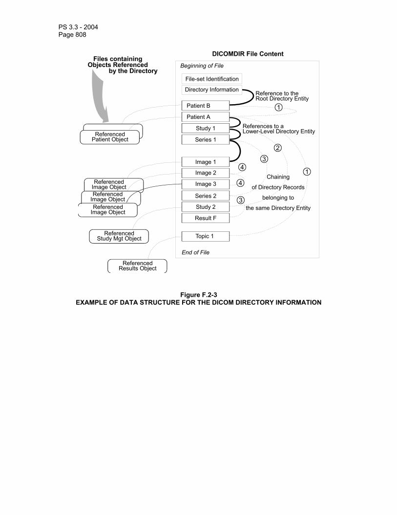
PS 3.3 - 2004 Page 808
Topic 1
File-set Identification
Directory Information
Beginning of File
End of File
Files containingObjects Referenced
by the Directory
DICOMDIR File Content
ReferencedPatient Object
ReferencedImage Object
ReferencedImage Object
ReferencedImage Object
ReferencedResults Object
ReferencedStudy Mgt Object
Study 1
Series 1
Series 2
Study 2
Result F
Patient B
Patient A
Image 1
Image 2
Image 3
1
2
34
4
3
1
Reference to theRoot Directory Entity
References to aLower-Level Directory Entity
Chaining
of Directory Records
belonging to
the same Directory Entity
Figure F.2-3 EXAMPLE OF DATA STRUCTURE FOR THE DICOM DIRECTORY INFORMATION
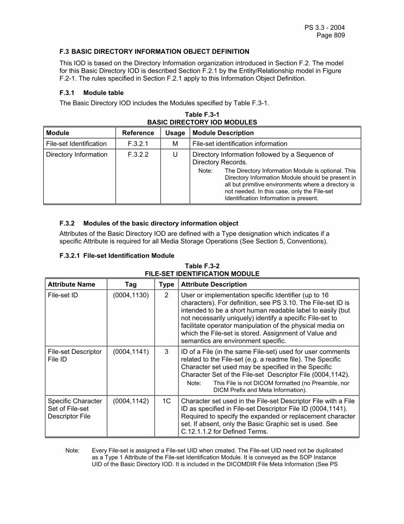
PS 3.3 - 2004 Page 809
F.3 BASIC DIRECTORY INFORMATION OBJECT DEFINITION
This IOD is based on the Directory Information organization introduced in Section F.2. The model for this Basic Directory IOD is described Section F.2.1 by the Entity/Relationship model in Figure F.2-1. The rules specified in Section F.2.1 apply to this Information Object Definition.
F.3.1 Module table The Basic Directory IOD includes the Modules specified by Table F.3-1.
Table F.3-1 BASIC DIRECTORY IOD MODULES
Module Reference Usage Module Description File-set Identification F.3.2.1 M File-set identification information Directory Information F.3.2.2 U Directory Information followed by a Sequence of
Directory Records. Note: The Directory Information Module is optional. This
Directory Information Module should be present in all but primitive environments where a directory is not needed. In this case, only the File-set Identification Information is present.
F.3.2 Modules of the basic directory information object Attributes of the Basic Directory IOD are defined with a Type designation which indicates if a specific Attribute is required for all Media Storage Operations (See Section 5, Conventions).
F.3.2.1 File-set Identification Module Table F.3-2
FILE-SET IDENTIFICATION MODULE Attribute Name Tag Type Attribute Description File-set ID (0004,1130) 2 User or implementation specific Identifier (up to 16
characters). For definition, see PS 3.10. The File-set ID is intended to be a short human readable label to easily (but not necessarily uniquely) identify a specific File-set to facilitate operator manipulation of the physical media on which the File-set is stored. Assignment of Value and semantics are environment specific.
File-set Descriptor File ID
(0004,1141) 3 ID of a File (in the same File-set) used for user comments related to the File-set (e.g. a readme file). The Specific Character set used may be specified in the Specific Character Set of the File-set Descriptor File (0004,1142).
Note: This File is not DICOM formatted (no Preamble, nor DICM Prefix and Meta Information).
Specific Character Set of File-set Descriptor File
(0004,1142) 1C Character set used in the File-set Descriptor File with a File ID as specified in File-set Descriptor File ID (0004,1141). Required to specify the expanded or replacement character set. If absent, only the Basic Graphic set is used. See C.12.1.1.2 for Defined Terms.
Note: Every File-set is assigned a File-set UID when created. The File-set UID need not be duplicated
as a Type 1 Attribute of the File-set Identification Module. It is conveyed as the SOP Instance UID of the Basic Directory IOD. It is included in the DICOMDIR File Meta Information (See PS

PS 3.3 - 2004 Page 810
3.10)
F.3.2.2 Directory Information Module This Module contains a sequence of Directory Records forming one or more Directory Entities. This Module defines at least one Directory Entity, the Root Directory Entity (which may be empty). Each Directory Record is composed of Directory Elements (marked by a ">"). They include:
a. an offset pointer to another Directory Record of the Same Directory Entity
b. an offset pointer to a lower level Directory Entity
c. a Referenced File pointed to by the Directory Record
d. a set of keys representative of the information contained in the Referenced File
Table F.3-3 DIRECTORY INFORMATION MODULE
Attribute Name Tag Type Attribute Description Offset of the First Directory Record of the Root Directory Entity
(0004,1200) 1 Offset of the first byte (of the Item Data Element) of the first Directory Record of the Root Directory Entity. This Offset is a number of bytes starting with the first byte of the File Meta Information. When the Root Directory Entity contains no Directory Record, this offset shall be set to 00000000H.
Note: This offset includes the File Preamble and the DICM Prefix.
Offset of the Last Directory Record of the Root Directory Entity
(0004,1202) 1 Offset of the first byte (of the Item Data Element) of the last Directory Record of the Root Directory Entity. This Offset is a number of bytes starting with the first byte of the File Meta Information. When the Root Directory Entity contains no Directory Record, this offset shall be set to 00000000H.
Note: This offset includes the File Preamble and the DICM Prefix.
File-set Consistency Flag
(0004,1212) 1 When set, this Flag indicates that an inconsistency within the Directory or between the Directory and the Files of the File-set may exist. Potential recovery actions are implementation specific and are beyond the scope of this Standard. Enumerated Values:
0000H: no known inconsistencies FFFFH: the FSR or FSU shall assume that inconsistencies
are present. This flag shall be set by implementations before a File-set update which, if interrupted, may result in an inconsistent File-set.
Note: There may be error conditions where an inconsistency is present but this flag is not set. There may also be conditions where no inconsistencies are present but the flag is set.
Directory Record Sequence
(0004,1220) 2 Sequence of zero or more repeating Items where each Item contains a Directory Record by including the Directory Elements from (0004,1400) to (0004,1511) and Record selection Keys as defined below (marked with a >). A zero length Value indicates that no Directory Records are contained in the Root Directory Entity.

PS 3.3 - 2004 Page 811
>Offset of the Next Directory Record
(0004,1400) 1C Offset of the first byte (of the Item Data Element) of the next Directory Record of the same Directory Entity. This Offset is an unsigned integer representing a number of bytes starting with the first byte of the File Meta-information. A zero offset shall be used to mean that there is no other Directory Record in this Directory Entity. Required if the Directory Record Sequence (0004,1220) is not zero length. This Offset may be used to keep an inactive Record (0004,1410) chained with the next Directory Record of the same Directory Entity.
Note: This offset includes the File Preamble and the DICM Prefix.
>Record In-use Flag
(0004,1410) 1C This flag facilitates the deletion of referenced files. Enumerated Values:
FFFFH = record is in use. 0000H = record is inactive. All attributes of an inactive
Directory Record except (0004,1400) and (0004,1410) shall be ignored.
Other Values are reserved and shall not be set by File-set Creators, but if present shall be interpreted as FFFFH by File-set Readers or Updaters. Required if the Directory Record Sequence (0004,1220) is not zero length. If a Directory Record is changed from in use to inactive, the FSU shall ensure that all Directory Records of referenced lower-level Directory Entities are changed to inactive.
>Offset of Referenced Lower-Level Directory Entity
(0004,1420) 1C Offset of the first byte (of the Item Data Element) of the first Directory Record of the Referenced Lower Level Directory Entity. This Offset is a number of bytes starting with the first byte of the File Meta Information. Required if the Directory Record Sequence (0004,1220) is not zero length. When no lower-level Directory Entity (containing at least one Directory Record) is referenced, this Attribute shall have a Value of 00000000H.
Note: This offset includes the File Preamble and the DICM Prefix.
>Directory Record Type
(0004,1430) 1C Defines a specialized type of Directory Record by reference to its position in the Media Storage Directory Information Model (see Section F.4). Required if the Directory Record Sequence (0004,1220) is not zero length. Enumerated Values (see Section F.5): PATIENT STUDY SERIES IMAGE OVERLAY MODALITY LUT VOI LUT CURVE TOPIC VISIT RESULTS INTERPRETATION STUDY COMPONENT STORED PRINT RT DOSE RT STRUCTURE SET RT PLAN RT TREAT RECORD PRESENTATION WAVEFORM SR DOCUMENT KEY OBJECT DOC SPECTROSCOPY RAW DATA REGISTRATION FIDUCIAL

PS 3.3 - 2004 Page 812
PRIVATE = Privately defined record hierarchy position. Type shall be defined by Private Record UID (0004,1432). MRDR = Special Directory Record which allows indirect reference to a File by multiple Directory Records. Instead of directly referencing a File by its Referenced File ID (0004,1500), a Directory Record of any of the Types define above (except MRDR) may reference a Multi-Referenced File Directory Record which in turn will reference the File by its File ID.
Note: Enumerated Values PRINT QUEUE, FILM SESSION, FILM BOX, and IMAGE BOX were previously defined in DICOM for this Attribute. They are now retired. See PS3.3-1998.
>Private Record UID
(0004,1432) 1C Required if the Directory Record Type (0004,1430) is of Value PRIVATE. This UID is used to define a non-standard type of Directory Record by reference to its position in a private extension to the Basic Directory IOD Information Model (see Section F.5). This UID shall be registered according to the procedures defined in PS 3.5. Its meaning may or may not be specified in a Conformance Statement.
>Referenced File ID
(0004,1500) 1C A Multiple Value (See PS 3.5) which represents the ordered components of the File ID containing a "referenced object" or Referenced SOP Instance. A maximum of 8 components, each from 1 to 8 characters shall be used (see Section 8.2).
Note: The Referenced File ID provides the means to "locate" the File through the DICOM File Service provided by the Media Format Layer.
All referenced Files shall be with the File-set to which the Directory belongs. Any File within the File-set (to which the Directory belongs) shall be referenced by at most one Directory Record. When the Directory Record does not reference any SOP Instance this attribute shall not be present.To reference a single File by more than one Directory Record, a special Directory Record of Directory Record Type (0004,1430) MRDR is used. The Referenced File ID (0004,1500) shall be absent and the MRDR Directory Record Offset (0004, 1504) shall be used to reference the MRDR which indirectly references the File.
>MRDR Directory Record Offset
(0004,1504) 1C Offset of the first byte (of the Item Data Element) of the Multi-Referenced File Directory Record. This Offset is a number of bytes starting with the first byte of the File Meta Information. When the Directory Record does not reference any SOP Instance this attribute shall not be present. Required if the Directory Record indirectly references a SOP Instance by a MRDR. Shall not be present if the Referenced File ID (0004,1500) is used for direct reference. Shall not be present in a Multi-Referenced File Directory Record.
Note: This offset includes the File Preamble and the DICM Prefix.
>Referenced SOP Class UID in File
(0004,1510) 1C Unique ID for the SOP Class of the Instance stored in the referenced File. This UID shall be present whether the File is referenced directly by Referenced File ID (0004,1500) or indirectly by an MRDR Directory Record Offset (0004,1504). Required only if the Directory Record references a SOP Instance. Shall not be used in a Multi-Referenced File Directory

PS 3.3 - 2004 Page 813
Record. >Referenced SOP Instance UID in File
(0004,1511) 1C Unique Identifier for the SOP Instance stored in the referenced file. This UID shall be present whether the File is referenced directly by Referenced File ID (0004,1500) or indirectly by an MRDR Directory Record Offset. Required only if the Directory Record references a SOP Instance. Shall not be used in a Multi-Referenced File Directory Record.
>Referenced Transfer Syntax UID in File
(0004,1512) 1C Unique Identifier for the Transfer Syntax used to encode the Instance stored in the referenced file. This UID shall be present whether the File is referenced directly by Referenced File ID (0004,1500) or indirectly by an MRDR Directory Record Offset. Required only if the Directory Record references a SOP Instance. Shall not be used in a Multi-Referenced File Directory Record.
>Referenced Related General SOP Class UID in File
(0004,151A) 1C Unique ID for the Related General SOP Class(es) related to the SOP Class of the Instance stored in the referenced file. Required if the Directory Record references a SOP Instance that encodes the Related General SOP Class UID (0008,001A). Shall not be used in a Multi-Referenced File Directory Record.
Note: This may be useful to an FSR that does not support the SOP Class of the referenced Instance, but which does support one of the Related General SOP Classes.
>Record Selection Keys
See F.5 See F.5
A number of DICOM Data Elements which contain specific keys defined for each type of Directory Record (0004,1430) defined in Section F.5.
F.4 BASIC DIRECTORY IOD INFORMATION MODEL
The Basic Directory IOD Information Model defines the relationship between the various types of Directory Records which may be used in constructing DICOM Directories. This model is based on the DICOM Application Model defined in this part of the DICOM Standard. Entities in this Model correspond to Directory Records (DR). These are shown as rectangular boxes. Each Directory Record in this model is part of a Directory Entity (not shown except for the Root Entity) which is referenced by a Directory Record of a higher-level Directory Entity (e.g., a Study Directory Record references a Directory Entity which includes Directory Records describing the content of the Study).
Each Directory Record has a number of mandatory and optional keys which are not shown on this model. They are defined in Section F.5. Conventions used are those used by this part of the DICOM Standard. The model is depicted as an entity/relationship model in Figure F.4-1. These Directory Record relationships are fully specified in Table F.4-1.
Table F.4-1 RELATIONSHIP BETWEEN DIRECTORY RECORDS
Directory Record Type Section Directory Record Types which may be included in the next lower-level directory Entity
(Root Directory Entity) PATIENT, TOPIC, PRIVATE
PATIENT F.5.1 STUDY, PRIVATE

PS 3.3 - 2004 Page 814
STUDY F.5.2 SERIES, VISIT, RESULTS, STUDY COMPONENT PRIVATE
SERIES F.5.3 IMAGE, OVERLAY, MODALITY LUT, VOI LUT, CURVE, STORED PRINT, RT DOSE, RT STRUCTURE SET, RT PLAN, RT TREAT RECORD, PRESENTATION, WAVEFORM, SR DOCUMENT, KEY OBJECT DOC, SPECTROSCOPY, RAW DATA, REGISTRATION, FIDUCIAL, PRIVATE
IMAGE F.5.4 PRIVATE OVERLAY F.5.5 PRIVATE MODALITY LUT F.5.6 PRIVATE VOI LUT F.5.7 PRIVATE CURVE F.5.8 PRIVATE STORED PRINT F.5.18 PRIVATE RT DOSE F.5.19 PRIVATE RT STRUCTURE SET F.5.20 PRIVATE RT PLAN F.5.21 PRIVATE RT TREAT RECORD F.5.22 PRIVATE PRESENTATION F.5.23 PRIVATE WAVEFORM F.5.24 PRIVATE SR DOCUMENT F.5.25 PRIVATE KEY OBJECT DOC F.5.26 PRIVATE SPECTROSCOPY F.5.27 PRIVATE RAW DATA F.5.28 PRIVATE REGISTRATION F.5.29 PRIVATE FIDUCIAL F.5.30 PRIVATE TOPIC F.5.9 STUDY, SERIES, IMAGE, OVERLAY, MODALITY LUT, VOI
LUT, CURVE, STORED PRINT, RT DOSE, RT STRUCTURE SET, RT PLAN, RT TREAT RECORD, PRESENTATION, WAVEFORM, SR DOCUMENT, KEY OBJECT DOC, SPECTROSCOPY, RAW DATA, REGISTRATION, FIDUCIAL, PRIVATE
VISIT F.5.10 PRIVATE RESULTS F.5.11 INTERPRETATION, PRIVATE INTERPRETATION F.5.12 PRIVATE STUDY COMPONENT F.5.13 PRIVATE PRIVATE F.6.1 PRIVATE, (any of the above as privately defined) MRDR F.6.2 (Not applicable)
Note: Directory Record Types PRINT QUEUE, FILM SESSION, FILM BOX, and IMAGE BOX were previously defined in DICOM. They have been retired. See PS 3.3-1998.
PS 3.3 - 2004 Page 815
F.5 DEFINITION OF SPECIFIC DIRECTORY RECORDS
The following Sections specify a number of Directory Records which were introduced by the Basic Directory IOD Information Model presented in Section F.4. For each one, it identifies the SOP Classes which may be referenced and the related mandatory keys. Keys are assigned a Type designation which indicates if it is required for all Media Storage Operations of the Directory (See Section 5, Conventions).
Type 2 and Type 3 Keys may be changed to Type 1 and Type 2 or 3 respectively by Application Profiles defined in PS 3.11 of the DICOM standard. Keys based on Private Data Elements, or Private Keys may also be used in addition to Standard defined Keys. However such Private keys may be ignored by any File-set Reader or Updater.

PS 3.3 - 2004 Page 816
Patient DR
Study DR
references
StudyComponent DR
Results DR
references
Interpretation DR
Image DR
Curve DR
Overlay DR
Modality LUT DR
VOI LUT DR
Stored Print DR
RT Dose DR
0-n
1
1
1-n
1
0-n
Root DirectoryEntity
includes
1
0-n
Topic DR
0-n
references
1
0-n
RT Structure SetDR
RT Plan DR
RT TreatmentRecord DR
Visit DR
Series DR
references1
0-n
0-n
0-n
0-n
0-n
0-n
0-n
0-n
0-n
0-n
references
Study DR
0-n
1references
0-n
1references
Series DR
0-n
BCB
0-n
B
C
The referencedsubset of the model
A reference to asubset of the model
Higher Level DR
Lower Level DR
references
The Higher-LevelDirectory Recordreferences aLower- LevelDirectory Entitythat includes theLower-LevelDirectory Record
Presentation DR0-nWaveform DR 0-n
SR Document DR0-n0-n
Fiducials DR 0-n
Spectroscopy DR
Registration DR0-n0-nRaw Data DR
Figure F.4-1 BASIC DIRECTORY IOD INFORMATION MODEL

PS 3.3 - 2004 Page 817
Note: Normalized Print media storage was previously defined in DICOM. It is now retired. See PS3.3 -1998.
F.5.1 Patient Directory Record Definition The Directory Record is based on the specification of Section F.3. It is identified by a Directory Record Type of Value "PATIENT." Table F.5-1 lists the set of keys with their associated Types for such a Directory Record Type. The description of these keys may be found in the Modules related to the Patient IOD or the Patient IE of Image IODs. This Directory Record shall be used to reference a Detached Patient Management SOP Instance. This Type of Directory Record may reference a Lower-Level Directory Entity which includes one or more Directory Records as defined in Table F.4-2.
Table F.5-1 PATIENT KEYS
Key Tag Type Attribute Description
Specific Character Set
(0008,0005) 1C Required if an extended or replacement character set is used in one of the keys
Patient's Name (0010,0010) 2 Patient ID (0010,0020) 1 Any other Attribute of the Patient IOD or Patient IE Modules
3
For a given File-set, the Patient ID shall be unique. This means that it shall not appear in different Patient Directory Records.
F.5.2 Study Directory record definition The Directory Record is based on the specification of Section F.3. It is identified by a Directory Record Type of Value "STUDY." Table F.5-2 lists the set of keys with their associated Types for such a Directory Record Type. The description of these keys may be found in the Modules related to the Study IOD or the Study IE of Image IODs. This Directory Record shall be used to reference a Detached Study Management SOP Instance. This Type of Directory Record may reference a Lower-Level Directory Entity which includes one or more Directory Records as defined in Table F.4-2.
Table F.5-2 STUDY KEYS
Key Tag Type Attribute Description Specific Character Set
(0008,0005) 1C Required if an extended or replacement character set is used in one of the keys
Study Date (0008,0020) 1 Study Time (0008,0030) 1 Study Description (0008,1030) 2 Study Instance UID
(0020,000D) 1C Required only if (0004,1511) is absent. (See Note)
Study ID (0020,0010) 1 Accession Number (0008,0050) 2 Any other Attribute 3

PS 3.3 - 2004 Page 818
of the Study IOD or Study IE Modules
Note: The Study Instance UID shall be present as a mandatory key only if no file is referenced by this
Directory Record. In the case where this Directory Record references a file, the Directory Record contains in the Referenced SOP Instance UID in File (0004,1511). In this case (0004,1511) may be used as a "pseudo" Directory Record Key (See Table F.3-3) and need not be duplicated.
F.5.3 Series Directory Record Definition The Directory Record is based on the specification of Section F.3. It is identified by a Directory Record Type of Value "SERIES." Table F.5-3 lists the set of keys with their associated Types for such a Directory Record Type. The description of these keys may be found in the Modules related to the Series IE and Equipment IE of Image IODs. This type of Directory Record may reference a Lower-Level Directory Entity which includes one or more Directory Records as defined in Table F.4-2.
Table F.5-3 SERIES KEYS
Key Tag Type Attribute Description Specific Character Set
(0008,0005) 1C Required if an extended or replacement character set is used in one of the keys
Modality (0008,0060) 1 Series Instance UID
(0020,000E) 1
Series Number (0020,0011) 1 Icon Image Sequence
(0088,0200) 3 This Icon Image is representative of the Series. It may or may not correspond to one of the images of the Series.
> Include ‘Image Pixel Macro’ Table C.7-11b
See Section F.7 of this Part.
Any other Attribute of the Series IE Modules
3
F.5.4 Image directory record definition The Directory Record is based on the specification of Section F.3. It is identified by a Directory Record Type of Value "IMAGE." Table F.5-4 lists the set of keys with their associated Types for such a Directory Record Type. The description of these keys may be found in the Modules related to the Image IE of Image IODs. This Directory Record shall be used to reference an Image SOP Instance. This type of Directory Record may reference a Lower-Level Directory Entity which includes one or more Directory Records as defined in Table F.4-2.

PS 3.3 - 2004 Page 819
Table F.5-4 IMAGE KEYS
Key Tag Type Attribute Description Specific Character Set
(0008,0005) 1C Required if an extended or replacement character set is used in one of the keys.
Instance Number (0020,0013) 1 Icon Image Sequence
(0088,0200) 3 This Icon Image is representative of the Image.
> Include ‘Image Pixel Macro’ Table C.7-11b
See Section F.7 of this Part.
Any other Attribute of the Image IE Modules
3
Note: Because (0004,1511) Referenced SOP Instance UID in File may be used as a "pseudo"
Directory Record Key (See Table F.3-3), it is not duplicated in this list of keys.
F.5.5 Standalone overlay directory record definition The Directory Record is based on the specification of Section F.3. It is identified by a Directory Record Type of Value "OVERLAY." Table F.5-5 lists the set of keys with their associated Types for such a Directory Record Type. The description of these keys may be found in the Modules related to the Overlay IE of Image IODs. This Directory Record shall be used to reference a Standalone Overlay Image SOP Instance. This Type of Directory Record may reference a Lower-Level Directory Entity which includes one or more Directory Records as defined in Table F.4-2.
Table F.5-5 OVERLAY KEYS
Key Tag Type Attribute Description Specific Character Set
(0008,0005) 1C Required if an extended or replacement character set is used in one of the keys.
Overlay Number (0020,0022) 1 Icon Image Sequence
(0088,0200) 3
> Include ‘Image Pixel Macro’ Table C.7-11b
See Section F.7 of this Part.
Any other Attribute of the Overlay IE Modules
3
Note: Because (0004,1511) Referenced SOP Instance UID in File may be used as a "pseudo"
Directory Record Key (See Table F.3-3), it is not duplicated in this list of keys.
F.5.6 Standalone modality LUT directory record definition The Directory Record is based on the specification of Section F.3. It is identified by a Directory Record Type of Value "MODALITY LUT." Table F.5-6 lists the set of keys with their associated Types for such a Directory Record Type. The description of these keys may be found in the Modules related to the Modality LUT IE of Image IODs. This Directory Record shall be used to reference a Standalone Modality LUT SOP Instance. This Type of Directory Record may
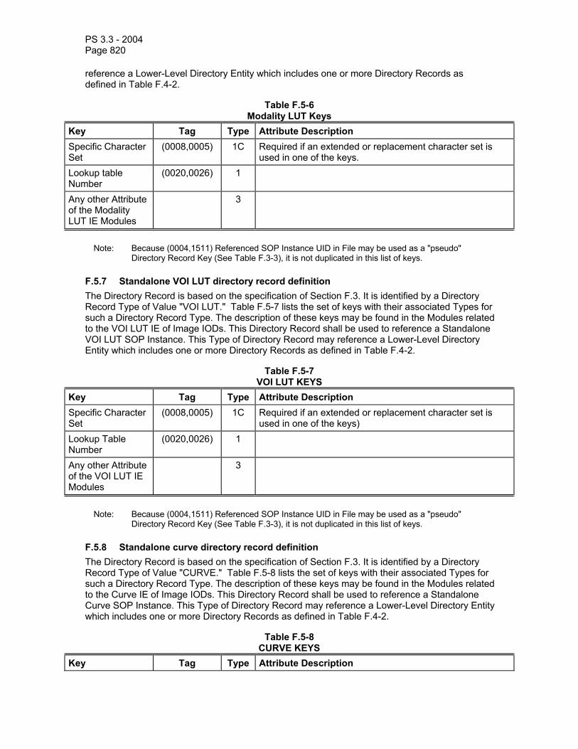
PS 3.3 - 2004 Page 820
reference a Lower-Level Directory Entity which includes one or more Directory Records as defined in Table F.4-2.
Table F.5-6 Modality LUT Keys
Key Tag Type Attribute Description Specific Character Set
(0008,0005) 1C Required if an extended or replacement character set is used in one of the keys.
Lookup table Number
(0020,0026) 1
Any other Attribute of the Modality LUT IE Modules
3
Note: Because (0004,1511) Referenced SOP Instance UID in File may be used as a "pseudo"
Directory Record Key (See Table F.3-3), it is not duplicated in this list of keys.
F.5.7 Standalone VOI LUT directory record definition The Directory Record is based on the specification of Section F.3. It is identified by a Directory Record Type of Value "VOI LUT." Table F.5-7 lists the set of keys with their associated Types for such a Directory Record Type. The description of these keys may be found in the Modules related to the VOI LUT IE of Image IODs. This Directory Record shall be used to reference a Standalone VOI LUT SOP Instance. This Type of Directory Record may reference a Lower-Level Directory Entity which includes one or more Directory Records as defined in Table F.4-2.
Table F.5-7 VOI LUT KEYS
Key Tag Type Attribute Description Specific Character Set
(0008,0005) 1C Required if an extended or replacement character set is used in one of the keys)
Lookup Table Number
(0020,0026) 1
Any other Attribute of the VOI LUT IE Modules
3
Note: Because (0004,1511) Referenced SOP Instance UID in File may be used as a "pseudo"
Directory Record Key (See Table F.3-3), it is not duplicated in this list of keys.
F.5.8 Standalone curve directory record definition The Directory Record is based on the specification of Section F.3. It is identified by a Directory Record Type of Value "CURVE." Table F.5-8 lists the set of keys with their associated Types for such a Directory Record Type. The description of these keys may be found in the Modules related to the Curve IE of Image IODs. This Directory Record shall be used to reference a Standalone Curve SOP Instance. This Type of Directory Record may reference a Lower-Level Directory Entity which includes one or more Directory Records as defined in Table F.4-2.
Table F.5-8 CURVE KEYS
Key Tag Type Attribute Description

PS 3.3 - 2004 Page 821
Specific Character Set
(0008,0005) 1C Required if an extended or replacement character set is used in one of the keys.
Curve Number (0020,0024) 1 Any other Attribute of the Curve IE Modules
3
Note: Because (0004,1511) Referenced SOP Instance UID in File may be used as a "pseudo"
Directory Record Key (See Table F.3-3), it is not duplicated in this list of keys.
F.5.9 Topic directory record definition The Topic Directory Record is intended to collect a set of subordinate Directory Records. It uses simple textual descriptions as keys. The Directory Record is based on the specification of Section F.3. It is identified by a Directory Record Type of Value "TOPIC." Table F.5-9 lists the set of keys with their associated Types for such a Directory Record Type. This Type of Directory Record may reference a Lower-Level Directory Entity which includes one or more Directory Records as defined in Table F.4-2.
Table F.5-9 TOPIC KEYS
Key Tag Type Attribute Description Specific Character Set
(0008,0005) 1C Required if an extended or replacement character set is used
Topic Title (0088,0904) 1 Text title for the topic addressed by this Directory Record Topic Subject (0088,0906) 2 Short Text description of the subject addressed by this topicTopic Author (0088,0910) 2 Name of the author or creator of this topic Topic Key Words (0088,0912) 2 A multiple Value field including from 1 to 32 key-words
related to the topic. Note: For more complex Directory Records with additional keys, a PRIVATE Directory Record is
suggested rather than aTopic Directory Record.
F.5.10 Visit directory record definition The Directory Record is based on the specification of Section F.3. It is identified by a Directory Record Type of Value "VISIT." Table F.5-10 lists the set of keys with their associated Types for such a Directory Record Type. The description of these keys may be found in the Modules related to the Visit IOD. This Directory Record shall be used to reference a Detached Visit Management SOP Instance. This Type of Directory Record may reference a Lower-Level Directory Entity which includes one or more Directory Records as defined in Table F.4-2.

PS 3.3 - 2004 Page 822
Table F.5-10 VISIT KEYS
Key Tag Type Attribute Description Admitting Date (0038,0020) 2 Admission ID (0038,0010) 2 Institution Name (0008,0080) 2 Specific Character Set
(0008,0005) 1C Required if an extended or replacement character set is used in one of the keys
Any other Attribute of the Visit IOD Modules
3
Note: Because (0004,1511) Referenced SOP Instance UID in File may be used as a "pseudo"
Directory Record Key (See Table F.3-3), it is not duplicated in this list of keys.
F.5.11 Results directory record definition The Directory Record is based on the specification of Section F.3. It is identified by a Directory Record Type of Value "RESULTS." Table F.5-11 lists the set of keys with their associated Types for such a Directory Record Type. The description of these keys may be found in the Modules related to the Results IOD. This Directory Record shall be used to reference a Detached Results Management SOP Instance. This Type of Directory Record may reference a Lower-Level Directory Entity which includes one or more Directory Records as defined in Table F.4-2.
Table F.5-11 RESULT KEYS
Key Tag Type Attribute Description Results ID (4008,0040) 2 Instance Creation date (Results)
(0008,0012) 2
Specific Character Set
(0008,0005) 1C Required if an extended or replacement character set is used in one of the keys)
Any other Attribute of the Results IOD Modules
3
Note: Because (0004,1511) Referenced SOP Instance UID in File may be used as a "pseudo"
Directory Record Key (See Table F.3-3), it is not duplicated in this list of keys.
F.5.12 Interpretation directory record definition The Directory Record is based on the specification of Section F.3. It is identified by a Directory Record Type of Value "INTERPRETATION." Table F.5-12 lists the set of keys with their associated Types for such a Directory Record Type. The description of these keys may be found in the Modules related to the Interpretation IOD. This Directory Record shall be used to reference an Interpretation SOP Instance. This Type of Directory Record may reference a Lower-Level Directory Entity which includes one or more Directory Records as defined in Table F.4-2.

PS 3.3 - 2004 Page 823
Table F.5-12 INTERPRETATION KEYS
Key Tag Type Attribute Description Specific Character Set
(0008,0005) 1C Required if an extended or replacement character set is used in one of the keys
Interpretation Transcription Date
(4008,0108) 1
Interpretation Author
(4008,010C) 2
Interpretation Diagnosis Description
(4008,0115) 2
Interpretation Diagnosis Codes Sequence
(4008,0117) 2
>Code Value (0008,0100) 1C Required if (4008,0117) is present >Coding Scheme Designator
(0008,0102) 1C Required if (4008,0117) is present
>Code Meaning (0008,0104) 1C Required if (4008,0117) is present Interpretation ID (4008,0200) 1 Interpretation Type ID
(4008,0210) 2
Interpretation Status ID
(4008,0212) 2
Any Attribute of Interpretation related Modules
3
Note: Because (0004,1511) Referenced SOP Instance UID in File may be used as a "pseudo"
Directory Record Key (See Table F.3-3), it is not duplicated in this list of keys.
F.5.13 Study component directory record definition The Directory Record is based on the specification of Section F.3. It is identified by a Directory Record Type of Value "STUDY COMPONENT." Table F.5-13 lists the set of keys with their associated Types for such a Directory Record Type. The description of these keys may be found in the Modules related to the Study Component IOD. This Directory Record shall be used to reference a Study Component SOP Instance. This Type of Directory Record may reference a Lower-Level Directory Entity which includes one or more Directory Records as defined in Table F.4-2.

PS 3.3 - 2004 Page 824
Table F.5-13 STUDY COMPONENT KEYS
Key Tag Type Attribute Description Specific Character Set
(0008,0005) 1C Required if an extended or replacement character set is used in one of the keys
Modality (0008,0060) 1 Study Description (0008,1030) 2 Procedure Code Sequence
(0008,1032) 1
> Code Value (0008,0100) 1C Required if (0008,1032) is present > Coding Scheme Designator
(0008,0102) 1C Required if (0008,1032) is present
> Code Meaning (0008,0104) 1C Required if (0008,1032) is present Performing Physician's Name
(0008,1050) 2
Any Attribute of Study Component Modules
3
Note: Because (0004,1511) Referenced SOP Instance UID in File may be used as a "pseudo"
Directory Record Key (See Table F.3-3), it is not duplicated in this list of keys.
F.5.14 Print Queue Directory Record Definition This section was previously defined in DICOM. It is now retired. See PS 3.3-1998.
F.5.15 Film session directory record definition This section was previously defined in DICOM. It is now retired. See PS 3.3-1998.
F.5.16 Film box directory record definition This section was previously defined in DICOM. It is now retired. See PS 3.3-1998.
F.5.17 Basic image box directory record definition This section was previously defined in DICOM. It is now retired. See PS 3.3-1998.
F.5.18 Stored Print Directory Record Definition The Directory Record is based on the specification of Section F.3. It is identified by a Directory Record Type of Value "STORED PRINT". Table F.5-18 lists the set of keys with their associated Types for such a Directory Record Type. The description of these keys may be found in the Modules related to Stored Print IODs. This Directory Record shall be used to reference a Stored Print SOP Instance. This Type of Directory Record may reference a Lower-Level Directory Entity which includes one or more Directory Records as defined in Table F.4-2.

PS 3.3 - 2004 Page 825
Table F.5-18 STORED PRINT KEYS
Key Tag Type Attribute Description Specific Character Set
(0008,0005) 1C Required if an extended or replacement character set is used in one of the keys.
Instance Number (0020,0013) 2 A number that identifies this film box. Icon Image Sequence
(0088,0200) 3 One or more Icons which represent the images (of the Film Box) which are referenced by the Stored Print SOP instance.
> Include ‘Image Pixel Macro’ Table C.7-11b See Section F.7 of this Part. Any other Attribute of the Image IE Modules
3
Note: Because (0004,1511) Referenced SOP Instance UID in File may be used as a "pseudo"
Directory Record Key (See Table F.3-3), it is not duplicated in this list of keys.
F.5.19 RT Dose Directory Record Definition This Directory Record is based on the specification of Section F.3. It is identified by a Directory Record Type of Value "RT DOSE". Table F.5-19 lists the set of keys with their associated Types for such a Directory Record Type. The description of these keys may be found in the Modules related to the Dose IE of the RT Dose IOD. This Directory Record shall be used to reference a RT Dose SOP instance. This Type of Directory Record may reference a Lower-Level Directory Entity which includes one or more Directory Records as defined in Table F.4-2.
Table F.5-19 RT DOSE KEYS
Key Tag Type Attribute Description Specific Character Set
(0008,0005) 1C Required if an extended or replacement character set is used in one of the keys.
Instance Number (0020,0013) 1 Dose Summation Type
(3004,000A) 1
Dose Comment (3004,0006) 3 Icon Image Sequence
(0088,0200) 3 This Icon Image is representative of the RT Dose.
> Include ‘Image Pixel Macro’ Table C.7-11b See Section F.7 of this part. Any other Attribute of the Dose IE Modules
3
Note: Because (0004,1511) Referenced SOP Instance UID in File may be used as a "pseudo"
Directory Record Key (see Table F.3-3), it is not duplicated in this list of keys.
F.5.20 RT Structure Set Directory Record Definition This Directory Record is based on the specification of Section F.3. It is identified by a Directory Record Type of Value "RT STRUCTURE SET". Table F.5-20 lists the set of keys with their associated Types for such a Directory Record Type. The description of these keys may be found
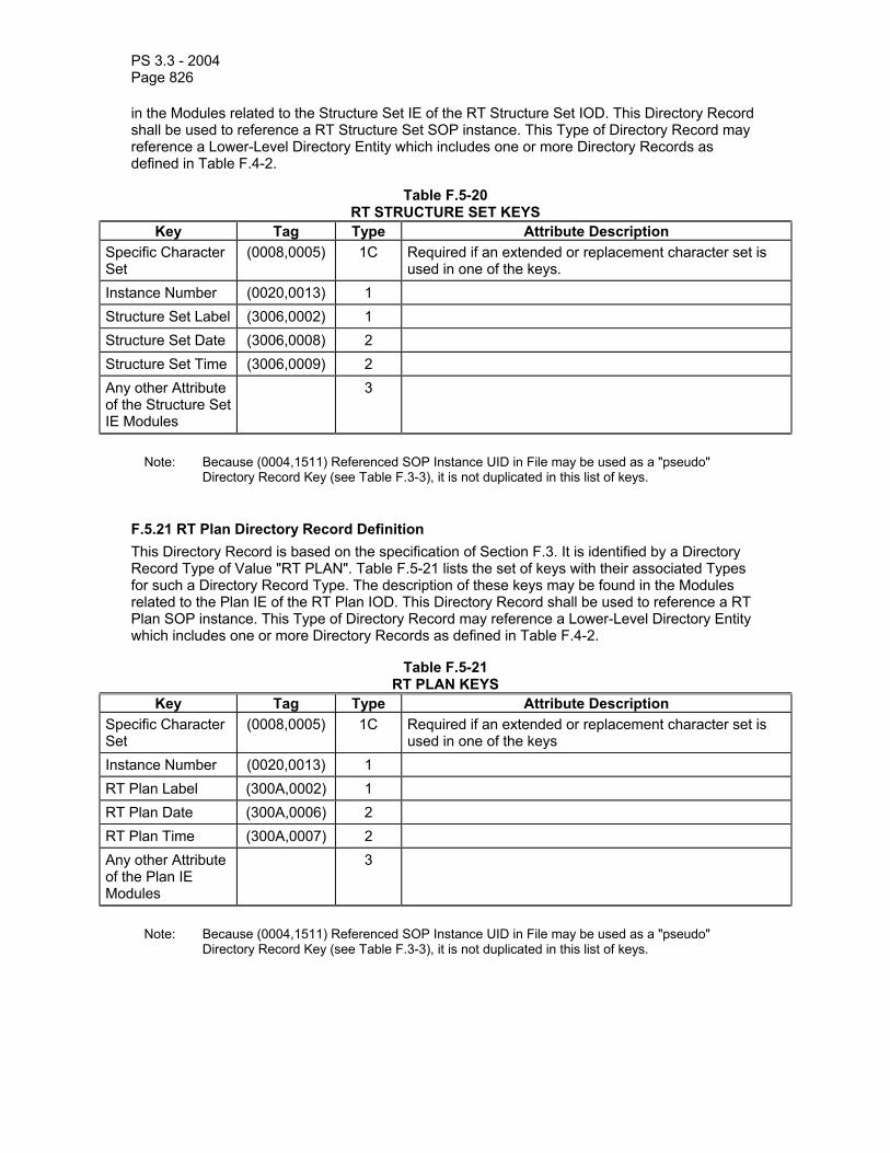
PS 3.3 - 2004 Page 826
in the Modules related to the Structure Set IE of the RT Structure Set IOD. This Directory Record shall be used to reference a RT Structure Set SOP instance. This Type of Directory Record may reference a Lower-Level Directory Entity which includes one or more Directory Records as defined in Table F.4-2.
Table F.5-20 RT STRUCTURE SET KEYS
Key Tag Type Attribute Description Specific Character Set
(0008,0005) 1C Required if an extended or replacement character set is used in one of the keys.
Instance Number (0020,0013) 1 Structure Set Label (3006,0002) 1 Structure Set Date (3006,0008) 2 Structure Set Time (3006,0009) 2 Any other Attribute of the Structure Set IE Modules
3
Note: Because (0004,1511) Referenced SOP Instance UID in File may be used as a "pseudo"
Directory Record Key (see Table F.3-3), it is not duplicated in this list of keys.
F.5.21 RT Plan Directory Record Definition This Directory Record is based on the specification of Section F.3. It is identified by a Directory Record Type of Value "RT PLAN". Table F.5-21 lists the set of keys with their associated Types for such a Directory Record Type. The description of these keys may be found in the Modules related to the Plan IE of the RT Plan IOD. This Directory Record shall be used to reference a RT Plan SOP instance. This Type of Directory Record may reference a Lower-Level Directory Entity which includes one or more Directory Records as defined in Table F.4-2.
Table F.5-21 RT PLAN KEYS
Key Tag Type Attribute Description Specific Character Set
(0008,0005) 1C Required if an extended or replacement character set is used in one of the keys
Instance Number (0020,0013) 1 RT Plan Label (300A,0002) 1 RT Plan Date (300A,0006) 2 RT Plan Time (300A,0007) 2 Any other Attribute of the Plan IE Modules
3
Note: Because (0004,1511) Referenced SOP Instance UID in File may be used as a "pseudo"
Directory Record Key (see Table F.3-3), it is not duplicated in this list of keys.

PS 3.3 - 2004 Page 827
F.5.22 RT Treatment Record Directory Record Definition This Directory Record is based on the specification of Section F.3. It is identified by a Directory Record Type of Value "RT TREAT RECORD". Table F.5-22 lists the set of keys with their associated Types for such a Directory Record Type. The description of these keys may be found in the Modules related to the Treatment Record IE of the RT Treatment Record IODs. This Directory Record shall be used to reference an RT Beams Treatment Record SOP instance, RT Brachy Treatment Record SOP instance, or RT Treatment Summary Record SOP instance. This Type of Directory Record may reference a Lower-Level Directory Entity which includes one or more Directory Records as defined in Table F.4-2.
Table F.5-22 RT TREATMENT RECORD KEYS
Key Tag Type Attribute Description Specific Character Set
(0008,0005) 1C Required if an extended or replacement character set is used in one of the keys
Instance Number (0020,0013) 1 Treatment Date (3008,0250) 2 Treatment Time (3008,0251) 2 Any other Attribute of the Treatment Record IE Modules
3
Note: Because (0004,1511) Referenced SOP Instance UID in File may be used as a "pseudo"
Directory Record Key (see Table F.3-3), it is not duplicated in this list of keys.
F.5.23 Presentation State Directory Record Definition The Directory Record is based on the specification of Section F.3. It is identified by a Directory Record Type of Value "PRESENTATION". Table F.5-23 lists the set of keys with their associated Types for such a Directory Record Type. The description of these keys may be found in the Modules related to Grayscale Softcopy Presentation State Storage IODs. This Directory Record shall be used to reference a Grayscale Softcopy Presentation State Storage SOP Instance. This Type of Directory Record may reference a Lower-Level Directory Entity which includes one or more Directory Records as defined in Table F.4-2.
Table F.5-23 PRESENTATION KEYS
Key Tag Type Attribute Description Specific Character Set
(0008,0005) 1C Required if an extended or replacement character set is used in one of the keys.
Instance Number (0020,0013) 1 A number that identifies this presentation state. Content Label (0070,0080) 1 A label that is used to identify this presentation. Content Description
(0070,0081) 2 A description of this presentation.
Presentation Creation Date
(0070,0082) 1 Date on which this presentation was created. Note: This date may be different from the date that the
DICOM SOP Instance was created, since the presentation state information contained may have been recorded earlier.
Presentation (0070,0083) 1 Time at which this presentation was created.

PS 3.3 - 2004 Page 828
Creation Time Note: This time may be different from the time that the DICOM SOP Instance was created, since the presentation state information contained may have been recorded earlier.
Content Creator’s Name
(0070,0084) 2 Name of operator saving the presentation state (such as a technologist or physician).
Referenced Series Sequence
(0008,1115) 1 Sequence of Repeating Items where each Item includes the Attributes of one or more Series.
>Series Instance UID
(0020,000E) 1C Unique identifier of a Series that is part of this Study. Required if sequence item is present.
>Referenced Image Sequence
(0008,1140) 1C Sequence of Repeating Items where each Item provides reference to a selected set of Image SOP Class/SOP Instance pairs that are part of this Study and the Series defined by Series Instance UID (0020,000E). Required if a sequence item is present.
>>Referenced SOP Class UID
(0008,1150) 1C Uniquely identifies the referenced SOP Class. Required if sequence item is present. Shall be the same for all Images referenced by this presentation state.
>>Referenced SOP Instance UID
(0008,1155) 1C Uniquely identifies the referenced SOP Instance. Required if sequence item is present.
Any other Attribute of the Presentation IE Modules
3
Note: Because (0004,1511) Referenced SOP Instance UID in File may be used as a "pseudo"
Directory Record Key (See Table F.3-3), it is not duplicated in this list of keys.
F.5.24 Waveform Directory Record Definition The Directory Record is based on the specification of Section F.3. It is identified by a Directory Record Type of Value "WAVEFORM". Table F.5-24 lists the set of keys with their associated Types for such a Directory Record Type. The description of these keys may be found in PS 3.3 of the DICOM Standard in the Modules related to the Waveform IE. This Directory Record shall be used to reference a Waveform SOP Instance. This Type of Directory Record may reference a Lower-Level Directory Entity which includes one or more Directory Records as defined in Table F.4-2.
Table F.5-24 WAVEFORM KEYS
Key Tag Type Attribute Description Specific Character Set
(0008,0005) 1C Required if an extended or replacement character set is used in one of the keys.
Instance Number (0020,0013) 1 Content Date (0008,0023) 1 Content Time (0008,0033) 1 Any other Attribute of the Waveform IE Modules
3

PS 3.3 - 2004 Page 829
Note: Because (0004,1511) Referenced SOP Instance UID in File may be used as a "pseudo" Directory Record Key (See Table F.3-3), it is not duplicated in this list of keys.
F.5.25 SR Document Directory Record Definition The Directory Record is based on the specification of Section F.3. It is identified by a Directory Record Type of Value "SR DOCUMENT". Table F.5-25 lists the set of keys with their associated Types for such a Directory Record Type. The description of these keys may be found in the Modules related to the Observation IE of Structured Report IOD. This Directory Record shall be used to reference an SR Document. This type of Directory Record may reference a Lower-Level Directory Entity which includes one or more Directory Records as defined in Table F.4-2.
Table F.5-25 SR DOCUMENT KEYS
Key Tag Type Attribute Description Specific Character Set (0008,0005) 1C Required if an extended or
replacement character set is used in one of the keys.
Instance Number (0020,0013) 1 Completion Flag (0040,A491) 1 Verification Flag (0040,A493) 1 Content Date (0008,0023) 1 Content Time (0008,0033) 1 Verification DateTime (0040,A030) 1C
Most recent Date and Time of verification among those defined in the Verifying Observer Sequence (0040,A073). Required if Verification Flag (0040,A493) is VERIFIED.
Concept Name Code Sequence (0040,A043) 1 Code describing the concept represented by the root Content Item (Document Title). This sequence shall contain exactly one Item.
Content Sequence (0040,A730) 1C Contains the Target Content Items that modify the Concept Name Code Sequence of the root Content Item (Document Title). Required if the root Content Item is the Source Content Item of HAS CONCEPT MOD relationships.
Any Attribute of the Document IE Modules
3
Note: Because (0004,1511) Referenced SOP Instance UID in File may be used as a "pseudo" Directory Record Key (See Table F.3-3), it is not duplicated in this list of keys.

PS 3.3 - 2004 Page 830
F.5.26 Key Object Document Directory Record Definition The Directory Record is based on the specification of Section F.3. It is identified by a Directory Record Type of Value "KEY OBJECT DOC". Table F.5-25 lists the set of keys with their associated Types for such a Directory Record Type. The description of these keys may be found in the Modules related to the Document IE of the Key Object Selection IOD. This Directory Record shall be used to reference a Key Object Selection Document. This type of Directory Record may reference a Lower-Level Directory Entity which includes one or more Directory Records as defined in Table F.4-1.
Table F.5-26 KEY OBJECT DOCUMENT KEYS
Key Tag Type Attribute Description Specific Character Set (0008,0005) 1C Required if an extended or
replacement character set is used in one of the keys.
Instance Number (0020,0013) 1 Content Date (0008,0023) 1 Content Time (0008,0033) 1 Concept Name Code Sequence (0040,A043) 1 Code describing the concept
represented by the root Content Item (Document Title). This sequence shall contain exactly one Item.
Content Sequence (0040,A730) 1C Contains the Target Content Items that modify the Concept Name Code Sequence of the root Content Item (Document Title). Required if the root Content Item is the Source Content Item of HAS CONCEPT MOD relationships.
Any Attribute of the Document IE Modules
3
Note: Because (0004,1511) Referenced SOP Instance UID in File may be used as a "pseudo" Directory Record Key (See Table F.3-3), it is not duplicated in this list of keys.
F.5.27 Spectroscopy directory record definition The Directory Record is based on the specification of Section F.3. It is identified by a Directory Record Type of Value "SPECTROSCOPY." Table F.5-27 lists the set of keys with their associated Types for such a Directory Record Type. The description of these keys may be found in the Modules related to the Spectroscopy IE of Spectroscopy IODs. This Directory Record shall be used to reference a Spectroscopy SOP Instance. This type of Directory Record may reference a Lower-Level Directory Entity that includes one or more Directory Records as defined in Table F.4-2.
Table F.5-27 SPECTROSCOPY KEYS

PS 3.3 - 2004 Page 831
Key Tag Type Attribute Description Specific Character Set
(0008,0005) 1C Required if an extended or replacement character set is used in one of the keys.
Image Type (0008,0008) 1 Content Date (0008,0023) 1 Content Time (0008,0033) 1 Instance Number (0020,0013) 1 Referenced Image Evidence Sequence
(0008,9092) 1C Required if present in the spectroscopy instance.
>Include 'SOP Instance Reference Macro' Table C.17-3 Number of Frames (0028,0008) 1 Rows (0028,0010) 1 Columns (0028,0011) 1 Data Point Rows (0028,9001) 1 Data Point Columns
(0028,9002) 1
Icon Image Sequence
(0088,0200) 3 This Icon Image is representative of the Spectroscopy instance.
>Image Pixel Module
See Section F.7 of this Part.
Any other Attribute of the Spectroscopy IE Modules
3
Note: Because (0004,1511) Referenced SOP Instance UID in File may be used as a "pseudo"
Directory Record Key (See Table F.3-3), it is not duplicated in this list of keys.
F.5.28 Raw Data directory record definition The Directory Record is based on the specification of Section F.3. It is identified by a Directory Record Type of Value "RAW DATA." Table F.5-28 lists the set of keys with their associated Types for such a Directory Record Type. The description of these keys may be found in the Modules related to the Raw Data IE of Raw Data IODs. This Directory Record shall be used to reference a Raw Data SOP Instance. This type of Directory Record may reference a Lower-Level Directory Entity that includes one or more Directory Records as defined in Table F.4-2.
Table F.5-28 RAW DATA KEYS
Key Tag Type Attribute Description Specific Character Set
(0008,0005) 1C Required if an extended or replacement character set is used in one of the keys.
Content Date (0008,0023) 1 Content Time (0008,0033) 1

PS 3.3 - 2004 Page 832
Instance Number (0020,0013) 2 Icon Image Sequence
(0088,0200) 3 This Icon Image is representative of the Raw Data instance.
>Image Pixel Module
See Section F.7 of this Part.
Any other Attribute of the Raw Data IE Modules
3
Note: Because (0004,1511) Referenced SOP Instance UID in File may be used as a "pseudo"
Directory Record Key (See Table F.3-3), it is not duplicated in this list of keys.
F.5.29 Registration directory record definition The Directory Record is based on the specification of Section F.3. It is identified by a Directory Record Type of Value "REGISTRATION." Table F.5-29 lists the set of keys with their associated Types for such a Directory Record Type. The description of these keys may be found in the Modules related to the Spatial Registration IE of the Spatial Registration IOD. This Directory Record shall be used to reference a Spatial Registration SOP Instance. This type of Directory Record may reference a Lower-Level Directory Entity that includes one or more Directory Records as defined in Table F.4-2.
Table F.5-29 REGISTRATION KEYS
Key Tag Type Attribute Description Specific Character Set
(0008,0005) 1C Required if an extended or replacement character set is used in one of the keys.
Content Date (0008,0023) 1 The date the content creation started. Content Time (0008,0033) 1 The time the content creation started. Instance Number (0020,0013) 1 A number that identifies this instance Content Label (0070,0080) 1 A label that is used to identify this registration. Content Description
(0070,0081) 2 A description of this registration.
Content Creator’s Name
(0070,0084) 2 Name of operator performing the registration (such as a technologist or physician).
Any other Attribute of the Spatial Registration IE Modules
3
Note: Because (0004,1511) Referenced SOP Instance UID in File may be used as a "pseudo"
Directory Record Key (See Table F.3-3), it is not duplicated in this list of keys.
F.5.30 Fiducial directory record definition The Directory Record is based on the specification of Section F.3. It is identified by a Directory Record Type of Value "FIDUCIAL." Table F.5-30 lists the set of keys with their associated Types for such a Directory Record Type. The description of these keys may be found in the Modules related to the Spatial Fiducials IE of Spatial Fiducials IOD. This Directory Record shall be used to reference a Spatial Fiducials SOP Instance. This type of Directory Record may reference a Lower-Level Directory Entity that includes one or more Directory Records as defined in Table F.4-2.
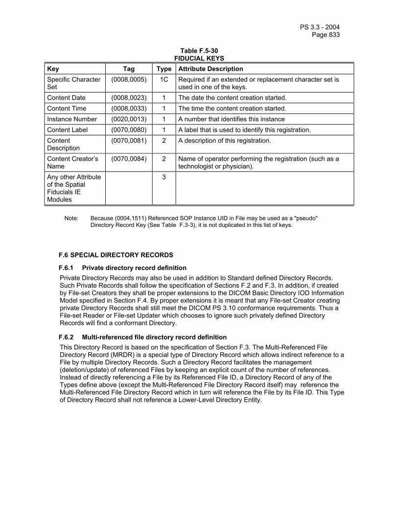
PS 3.3 - 2004 Page 833
Table F.5-30 FIDUCIAL KEYS
Key Tag Type Attribute Description Specific Character Set
(0008,0005) 1C Required if an extended or replacement character set is used in one of the keys.
Content Date (0008,0023) 1 The date the content creation started. Content Time (0008,0033) 1 The time the content creation started. Instance Number (0020,0013) 1 A number that identifies this instance Content Label (0070,0080) 1 A label that is used to identify this registration. Content Description
(0070,0081) 2 A description of this registration.
Content Creator’s Name
(0070,0084) 2 Name of operator performing the registration (such as a technologist or physician).
Any other Attribute of the Spatial Fiducials IE Modules
3
Note: Because (0004,1511) Referenced SOP Instance UID in File may be used as a "pseudo"
Directory Record Key (See Table F.3-3), it is not duplicated in this list of keys.
F.6 SPECIAL DIRECTORY RECORDS
F.6.1 Private directory record definition Private Directory Records may also be used in addition to Standard defined Directory Records. Such Private Records shall follow the specification of Sections F.2 and F.3. In addition, if created by File-set Creators they shall be proper extensions to the DICOM Basic Directory IOD Information Model specified in Section F.4. By proper extensions it is meant that any File-set Creator creating private Directory Records shall still meet the DICOM PS 3.10 conformance requirements. Thus a File-set Reader or File-set Updater which chooses to ignore such privately defined Directory Records will find a conformant Directory.
F.6.2 Multi-referenced file directory record definition This Directory Record is based on the specification of Section F.3. The Multi-Referenced File Directory Record (MRDR) is a special type of Directory Record which allows indirect reference to a File by multiple Directory Records. Such a Directory Record facilitates the management (deletion/update) of referenced Files by keeping an explicit count of the number of references. Instead of directly referencing a File by its Referenced File ID, a Directory Record of any of the Types define above (except the Multi-Referenced File Directory Record itself) may reference the Multi-Referenced File Directory Record which in turn will reference the File by its File ID. This Type of Directory Record shall not reference a Lower-Level Directory Entity.

PS 3.3 - 2004 Page 834
The following restrictions apply to this Directory Record: a. Offset of the Next Directory Record shall be set to 00000000H b. Offset of Referenced Lower-Level Directory Entity shall be set to 00000000H c. Directory Record Type shall be set to MRDR d. Referenced File ID shall be set to the File ID of the Multi-Referenced File e. Referenced SOP Class UID shall be absent f. Referenced SOP Instance UID shall be absent
One additional attribute is defined in Table 5.5-19 and shall be included as a "pseudo" Key.
Table F.6-1 MULTI-REFERENCED FILE KEYS
Key Tag Type Attribute Description Number of References
(0004,1600) 1 Number of References made by other Directory Records to this MDRD Directory Record. When set to 0000H the MRDR record is inactive. The Referenced File ID (0004,1510) value of the MRDR record shall be considered as invalid and ignored. Number of References (0004,1600) shall be reduced by one when a Directory Record of any Type (referencing this Multi-Referenced File Directory Record) is either deleted or when its Record In Use Flag (0004,1410) set to inactive. When a Directory Record of any Type (referencing this Multi-Referenced File Directory Record) is added, the Number of References (0004,1600) shall be increased by one.
Note: If the Number of References becomes zero, it is an implementation decision whether the MRDR Directory Record is deleted or left inactive and if the Multi-Referenced File is deleted.
F.7 ICON IMAGE KEY DEFINITION
An Icon Image may be used as a key representative of an Image, RT Dose, Stored Print, Series or Overlay in a corresponding Directory Record to allow an application to display icons which enable a user to select one or more from amongst several of them. It is based on the general purpose Image Pixel Macro (See Annex C).
The Icon Image Key corresponds to Data Element (0088,0200). It is defined as a Sequence which contains a single Item encapsulating the Data Set made of the Data Elements of the Icon Image. The Data Elements are defined by the Image Pixel Macro (see Section C.7.6.3).
The Image Pixel Macro usage is restricted in a few areas to facilitate general use in Directory Record across various modality environments. These restrictions are:
a. Only monochrome and palette color images shall be used. Samples per Pixel (0028,0002) shall have a Value of 1, Photometric Interpretation (0028,0004) shall have a Value of either MONOCHROME 1, MONOCHROME 2 or PALETTE COLOR, Planar Configuration (0028,0006) shall not be present
Note: True color icon images are not supported. This is due to the fact that the reduced size of the Icon Image makes the quality of a palette color image (with 256 colors) sufficient in most cases. This simplifies the handling of Icon Images by File-set Readers and File-set Updaters.

PS 3.3 - 2004 Page 835
b. If an FSR/FSU supports Icons (i.e. does not ignore them) then it shall support at least a maximum size of 64 by 64 Icons. An FSC may write Icons of any size. Icons larger than 64 by 64 may be ignored by FSRs and FSUs unless specialized by Application Profiles
c. Pixel samples have a Value of either 1 or 8 for Bits Allocated (0028,0100) and Bits Stored (0028,0101). High Bit (0028,0102) shall have a Value of one less than the Value used in Bit Stored
d. Pixel Representation (0028,0103) shall used an unsigned integer representation (Value 0000H)
e. Pixel Aspect Ratio (0028,0034) shall have a Value of 1:1 f. If a Palette Color lookup Table is used, an 8 Bit Allocated (0028,0100) shall be used

PS 3.3 - 2004 Page 836
Annex G Integration of Modality Worklist and Modality Performed Procedure Step in the Original DICOM Standard (Informative)
Retired. See PS 3.17.

PS 3.3 - 2004 Page 837
Annex H Retired

PS 3.3 - 2004 Page 838
Annex I Retired

PS 3.3 - 2004 Page 839
Annex J Waveforms (Informative)
Retired. See PS 3.17.

PS 3.3 - 2004 Page 840
Annex K SR Encoding Example (Informative)
Retired. See PS 3.17.

PS 3.3 - 2004 Page 841
Annex L Mammography CAD (Informative)
Retired. See PS 3.17.

PS 3.3 - 2004 Page 842
Annex M Chest CAD (Informative)
Retired. See PS 3.17.

PS 3.3 - 2004 Page 843
Annex N Explanation of Grouping Criteria for Multi-frame Functional Group IODs (Informative)
Retired. See PS 3.17.

PS 3.3 - 2004 Page 844
Annex O. Clinical Trial Identification Workflow Examples (Informative)
Retired. See PS 3.17.
PS 3.3 - 2004 Page 845
Annex P Index
( gggg,eeee) 806 (0004,1130) 821 (0004,1141) 821 (0004,1142) 821 (0004,1200) 822 (0004,1202) 822 (0004,1212) 822 (0004,1220) 822, 823, 824 (0004,1400) 822, 823 (0004,1410) 823, 846 (0004,1420) 823 (0004,1430) 824, 825 (0004,1432) 824 (0004,1500) 824, 825 (0004,1504) 825 (0004,1510) 825, 846 (0004,1511) 822, 825, 830, 831, 832, 833, 834, 835, 836, 837, 838, 839, 840, 841, 842, 843, 844, 845 (0004,1512) 825 (0004,151A) 825 (0004,1600) 846 (0008, 1197) 806 (0008,0001) 730 (0008,0005) 686, 721, 725, 726, 727, 776, 829, 830, 831, 832, 833, 834, 835, 836, 837, 838, 839, 840, 841, 842, 843,
844 (0008,0008) 98, 183, 184, 185, 186, 187, 188, 190, 191, 266, 270, 271, 272, 331, 332, 333, 334, 335, 336, 346, 348,
349, 352, 358, 360, 361, 362, 363, 364, 365, 366, 370, 372, 373, 375, 376, 377, 397, 402, 414, 415, 418, 439, 442, 445, 540, 543, 553, 556, 561, 579, 580, 582, 586, 588, 589, 590, 591, 592, 595, 596, 597, 598, 599, 618, 619, 620, 621, 622, 623, 624, 625, 631, 632, 634, 635, 637, 638, 639, 653, 654, 655, 658, 659, 660, 697
(0008,0012) 694, 721, 834 (0008,0013) 694, 721 (0008,0014) 721 (0008,0016) 721 (0008,0018) 721, 765, 766, 767, 768 (0008,001A) 721, 825 (0008,001B) 721 (0008,0020) 221, 252, 739, 830 (0008,0021) 223, 255, 529, 534, 535, 544, 547 (0008,0022) 266, 541, 543, 544 (0008,0023) 266, 302, 365, 659, 694, 770, 777, 789, 796, 840, 841, 842, 843, 844 (0008,0024) 668 (0008,0025) 674 (0008,002A) 262, 263, 266, 400, 588, 635, 660, 694, 697, 796 (0008,0030) 221, 252, 739, 830 (0008,0031) 223, 255, 529, 534, 535, 538, 539, 543, 544, 547 (0008,0032) 266, 368, 369, 535, 541, 543, 544 (0008,0033) 266, 284, 303, 365, 579, 659, 694, 697, 770, 777, 789, 796, 840, 841, 842, 843, 844 (0008,0034) 668 (0008,0035) 674 (0008,0050) 219, 228, 229, 236, 241, 252, 739, 772, 790, 830 (0008,0054) 223, 232, 244, 338, 756, 760, 765, 773 (0008,0060) 158, 159, 161, 163, 164, 166, 221, 224, 226, 231, 255, 258, 259, 319, 400, 408, 409, 436, 438, 550, 552,
574, 577, 617, 634, 659, 666, 717, 769, 789, 830, 836

PS 3.3 - 2004 Page 846
(0008,0064) 408, 411, 439 (0008,0068) 134, 136, 139, 553, 554, 559 (0008,0070) 264, 477, 494, 505, 723, 751, 763 (0008,0080) 70, 216, 264, 477, 494, 505, 723, 834 (0008,0081) 71, 216, 264, 477, 494, 505, 723 (0008,0082) 71, 216 (0008,0090) 217, 227, 236, 252, 739 (0008,0092) 217 (0008,0094) 217 (0008,0096) 217, 227, 252 (0008,0100) 66, 67, 68, 69, 237, 296, 578, 835, 836 (0008,0102) 66, 67, 69, 355, 367, 721, 722, 835, 836 (0008,0103) 66, 67, 69, 722 (0008,0104) 67, 68, 69, 355, 367, 368, 371, 835, 836 (0008,0105) 67, 68, 69 (0008,0106) 68, 69 (0008,0107) 68, 69 (0008,010B) 68, 69 (0008,010C) 722 (0008,010D) 68, 69 (0008,010F) 68, 69 (0008,0110) 66, 721 (0008,0112) 721 (0008,0114) 722 (0008,0115) 722 (0008,0116) 722 (0008,0201) 722 (0008,1010) 264, 723 (0008,1030) 224, 252, 739, 830, 836 (0008,1032) 224, 230, 253, 836 (0008,103E) 232, 255, 436 (0008,1040) 264, 477, 494, 505, 723 (0008,1048) 252 (0008,1049) 252 (0008,1050) 224, 231, 255, 836 (0008,1052) 224, 231, 255 (0008,1060) 222, 253, 739 (0008,1062) 222, 253 (0008,1070) 231, 255, 439, 463, 506, 517, 518, 525 (0008,1072) 231, 255 (0008,1080) 217, 254, 739 (0008,1084) 217, 254 (0008,1090) 264, 477, 495, 505, 723, 751, 763 (0008,1100) 219, 246 (0008,1110) 212, 216, 224, 226, 229, 235, 241, 245, 253, 771, 790 (0008,1111) 219, 238, 244, 256, 258, 436, 437, 553, 617, 634, 769, 789 (0008,1115) 73, 223, 244, 338, 339, 718, 773, 840 (0008,1120) 216, 219, 228, 249 (0008,1125) 212, 219 (0008,1130) 364, 398, 542, 674 (0008,113A) 268, 588, 635 (0008,1140) 223, 232, 256, 261, 266, 315, 338, 415, 418, 580, 581, 582, 588, 591, 635, 661, 668, 674, 676, 678, 679,
681, 685, 708, 716, 718, 765, 773, 802, 840 (0008,1145) 365, 398, 399, 542, 674 (0008,114A) 73, 694, 796 (0008,1150)72, 73, 212, 216, 219, 223, 224, 226, 228, 229, 232, 236, 239, 240, 241, 244, 245, 246, 249, 253, 256, 267,
271, 315, 316, 338, 365, 398, 415, 436, 441, 449, 451, 454, 455, 457, 464, 472, 478, 480, 496, 504, 507, 519, 542, 553, 580, 617, 634, 668, 674, 676, 678, 681, 685, 694, 696, 708, 716, 719, 738, 745, 746, 748, 749, 756, 760, 762, 763, 765, 767, 769, 772, 773, 789, 790, 792, 796, 805, 806, 840
(0008,1155) 73, 212, 216, 219, 223, 224, 226, 229, 232, 236, 239, 240, 241, 244, 245, 246, 249, 253, 256, 267, 315, 316, 338, 365, 398, 399, 415, 437, 441, 449, 451, 454, 455, 457, 464, 472, 478, 480, 496, 504, 507, 519,

PS 3.3 - 2004 Page 847
542, 553, 580, 617, 634, 667, 668, 674, 676, 678, 679, 681, 685, 694, 696, 708, 716, 719, 738, 739, 745, 746, 748, 749, 756, 760, 762, 764, 765, 766, 767, 769, 772, 773, 789, 790, 792, 796, 805, 806, 840
(0008,115A) 756 (0008,1160) 72, 266, 267, 315, 316, 415, 441, 446, 455, 457, 580, 681, 685, 716, 719, 748, 749, 765, 767, 792, 796,
802 (0008,1195) 241, 760 (0008,1197) 760, 808 (0008,1198) 760, 806, 808 (0008,1199) 760, 792, 805, 807, 808, 809 (0008,1250) 256 (0008,2111) 267, 269, 271, 272, 316, 415, 417, 558, 561, 660 (0008,2112) 267, 271, 316, 409, 429, 554, 560, 589, 591, 636, 660 (0008,2114) 269 (0008,2120) 399 (0008,2122) 399 (0008,2124) 398 (0008,2127) 399 (0008,2128) 399 (0008,2129) 399 (0008,212A) 398 (0008,2130) 399 (0008,2132) 399 (0008,2142) 284 (0008,2143) 284 (0008,2144) 284 (0008,2200) 406 (0008,2204) 406 (0008,2218) 73, 74, 256, 318, 555, 556, 577, 580, 666 (0008,2220) 73, 74, 578, 580 (0008,2228) 66, 73, 75, 577, 578 (0008,2229) 233 (0008,2230) 73, 75, 318, 555, 666 (0008,2240) 399 (0008,2242) 399 (0008,2244) 400 (0008,2246) 400 (0008,3001) 271 (0008,9007) 307, 313, 314, 591, 592, 599, 600, 601, 604, 605, 606, 607, 608, 609, 610, 611, 612, 613, 614, 615, 616,
626, 627, 631, 632, 637, 638, 639, 640, 641, 642, 643, 644, 645, 646, 648, 649, 650, 651, 652, 653, 654, 655, 658
(0008,9092) 588, 590, 635, 843 (0008,9121) 588, 635 (0008,9123) 796 (0008,9124) 316 (0008,9154) 589, 590, 636 (0008,9205) 182, 189, 275, 276, 337, 656 (0008,9206) 306, 313, 314, 630, 656, 657, 658 (0008,9207) 630, 632, 653, 656, 657, 658 (0008,9208) 591, 594, 630, 633 (0008,9209) 591, 594, 631, 633 (0008,9215) 267, 271, 316 (0008,9237) 589, 636 (0010,0010) 213, 228, 235, 240, 249, 337, 739, 829 (0010,0020) 213, 228, 235, 240, 249, 337, 739, 749, 756, 765, 829 (0010,0021) 213, 228, 235, 240, 249 (0010,0030) 214, 228, 235, 241, 249, 739 (0010,0032) 214, 249, 739 (0010,0040) 214, 228, 235, 241, 249, 739 (0010,0050) 214 (0010,0101) 215 (0010,0102) 215

PS 3.3 - 2004 Page 848
(0010,1000) 213, 249, 739 (0010,1001) 213, 249, 739 (0010,1005) 213 (0010,1010) 214, 254, 739 (0010,1020) 214, 254, 739 (0010,1030) 214, 254, 739 (0010,1040) 214 (0010,1060) 213 (0010,1080) 214 (0010,1081) 214 (0010,1090) 213 (0010,2000) 215 (0010,2110) 215 (0010,2150) 214 (0010,2152) 214 (0010,2154) 214 (0010,2160) 214, 249, 739 (0010,2180) 214, 254, 739 (0010,21A0) 215 (0010,21B0) 215, 254, 739 (0010,21C0) 215 (0010,21D0) 215 (0010,21F0) 214 (0010,4000) 215, 249, 739 (0012,0010) 250, 251 (0012,0020) 250, 251, 252 (0012,0021) 251 (0012,0030) 251 (0012,0031) 251, 252 (0012,0040) 251, 252 (0012,0042) 251, 252 (0012,0050) 254 (0012,0051) 254 (0012,0060) 260 (0018, 9307) 348 (0018, 9310) 348 (0018,0010) 282 (0018,0012) 184, 187, 190, 195, 282, 283, 324 (0018,0014) 282, 283, 324 (0018,0015) 73, 256, 343, 556 (0018,0020) 349, 350 (0018,0021) 349, 350 (0018,0022) 118, 346, 350, 415 (0018,0023) 350, 595, 598, 604 (0018,0024) 350 (0018,0025) 351 (0018,0026) 368, 539 (0018,0027) 297, 368, 539 (0018,0028) 368, 539 (0018,0029) 66, 297, 368, 539 (0018,002A) 282 (0018,0031) 367, 538 (0018,0034) 539 (0018,0035) 297, 368, 539 (0018,0036) 296 (0018,0038) 296 (0018,0039) 297 (0018,003A) 297 (0018,0040) 284 (0018,0050) 272, 306, 312, 313, 377 (0018,0060) 234, 344, 346, 419, 429, 433, 442, 651
PS 3.3 - 2004 Page 849
(0018,0070) 363, 366 (0018,0071) 363, 366, 531 (0018,0072) 284 (0018,0073) 531, 535 (0018,0074) 531 (0018,0075) 531 (0018,0080) 350, 600 (0018,0081) 350 (0018,0082) 350 (0018,0083) 351, 615 (0018,0084) 351 (0018,0085) 351 (0018,0086) 351 (0018,0087) 351, 590 (0018,0088) 351, 377, 587 (0018,0089) 351 (0018,0090) 643 (0018,0091) 350, 600 (0018,0093) 351, 604, 627 (0018,0094) 351, 604, 627 (0018,0095) 351, 611 (0018,1000) 264, 477, 495, 505, 723, 751, 763 (0018,1004) 344, 345 (0018,1010) 408 (0018,1011) 550 (0018,1012) 409 (0018,1014) 409 (0018,1016) 408 (0018,1017) 550 (0018,1018) 408 (0018,1019) 408 (0018,101A) 550 (0018,101B) 550 (0018,1020) 264, 723, 751, 763 (0018,1022) 408 (0018,1023) 408 (0018,1030) 232, 255 (0018,1040) 282 (0018,1041) 282, 283 (0018,1042) 282, 283 (0018,1043) 282, 283 (0018,1044) 282 (0018,1045) 367, 369 (0018,1046) 282, 283 (0018,1047) 282, 283 (0018,1048) 282 (0018,1049) 282, 283 (0018,1050) 264, 723 (0018,1060) 350, 375, 400, 540, 545 (0018,1061) 262, 365, 539 (0018,1062) 351, 375, 400, 541 (0018,1063) 105, 106, 108, 109, 284, 285, 375, 376, 396, 403, 414, 416, 418, 540, 543 (0018,1064) 375, 539, 543 (0018,1065) 105, 106, 108, 109, 284, 285, 396, 403, 412, 414, 416, 418 (0018,1066) 284 (0018,1067) 284 (0018,1068) 695, 697 (0018,1069) 695 (0018,106A) 262 (0018,106C) 262, 263 (0018,106E) 695, 697

PS 3.3 - 2004 Page 850
(0018,1070) 367, 538 (0018,1071) 367, 538 (0018,1072) 367, 368, 535, 538 (0018,1073) 367, 368, 538 (0018,1074) 367, 369, 538 (0018,1075) 535, 538, 544 (0018,1076) 538 (0018,1077) 538 (0018,1080) 351, 374, 400, 539, 540, 541 (0018,1081) 333, 351, 361, 375, 400, 534, 540, 541, 545 (0018,1082) 333, 351, 361, 375, 400, 534, 541 (0018,1083) 333, 351, 375, 541 (0018,1084) 333, 351, 375, 541 (0018,1085) 351, 374, 539 (0018,1086) 351, 374, 539 (0018,1088) 351, 352, 374, 400, 539 (0018,1090) 351 (0018,1094) 352 (0018,1100) 346, 352, 377, 530, 648 (0018,1110) 233, 234, 344, 347, 370, 373, 424, 428, 429, 572, 574, 646 (0018,1111) 344, 347, 424, 428, 430, 571, 574 (0018,1114) 424, 428, 572 (0018,1120) 347, 370, 372, 531, 536, 642 (0018,1121) 532 (0018,1130) 347, 363, 373, 642 (0018,1131) 363, 372, 373 (0018,1134) 423 (0018,1135) 418, 423 (0018,1136) 418, 423 (0018,1137) 418, 423 (0018,1138) 423, 573 (0018,113A) 573 (0018,1140) 347, 373, 641 (0018,1142) 370, 373 (0018,1143) 373 (0018,1144) 373, 374 (0018,1145) 370, 372 (0018,1147) 369, 419, 531, 564, 565, 566 (0018,1149) 369, 420, 421, 531, 564, 565, 566 (0018,1150) 234, 344, 347, 419, 429, 433, 442, 563 (0018,1151) 344, 347, 419, 429, 433, 442 (0018,1152) 344, 347, 419, 429, 433 (0018,1153) 344, 347, 419, 429, 433 (0018,1154) 419 (0018,1155) 419 (0018,1156) 432, 433 (0018,115A) 234, 419 (0018,115E) 233, 420, 430 (0018,1160) 234, 343, 347, 434, 651 (0018,1161) 419 (0018,1162) 419 (0018,1164) 345, 420, 565, 566, 682 (0018,1166) 419, 435 (0018,1170) 345, 347 (0018,1180) 344, 369, 532 (0018,1181) 369, 532 (0018,1182) 370, 371 (0018,1183) 370, 371 (0018,1184) 370, 371 (0018,1190) 344, 347, 420, 433, 651 (0018,1191) 432, 433
PS 3.3 - 2004 Page 851
(0018,11A0) 430, 573 (0018,11A2) 573 (0018,1200) 264, 265, 723, 751, 763 (0018,1201) 264, 265, 723, 751, 763 (0018,1210) 347, 377, 531, 648 (0018,1242) 284, 364, 366, 373, 376, 541, 544 (0018,1243) 364 (0018,1244) 284 (0018,1250) 352, 612 (0018,1251) 352, 613 (0018,1260) 344 (0018,1261) 344 (0018,1300) 364 (0018,1301) 364 (0018,1302) 364 (0018,1310) 352 (0018,1312) 352, 604 (0018,1314) 352, 600 (0018,1315) 352 (0018,1316) 352 (0018,1318) 352 (0018,1400) 345, 415, 417, 558, 560, 561 (0018,1401) 345, 558 (0018,1402) 345 (0018,1403) 345 (0018,1404) 345 (0018,1405) 345, 430 (0018,1450) 428, 573 (0018,1460) 428, 429 (0018,1470) 428 (0018,1480) 428 (0018,1491) 429 (0018,1495) 429 (0018,1500) 424 (0018,1508) 571, 572, 573, 574, 577 (0018,1510) 425, 426, 572, 575 (0018,1511) 425, 426, 572, 575 (0018,1520) 418, 425 (0018,1521) 418, 425 (0018,1530) 425, 573 (0018,1531) 425, 573 (0018,1600) 290, 291, 301 (0018,1602) 290 (0018,1604) 290 (0018,1606) 290 (0018,1608) 290 (0018,1610) 290 (0018,1612) 290 (0018,1620) 291 (0018,1622) 290, 291, 300, 301, 719 (0018,1623) 301 (0018,1700) 421, 422 (0018,1702) 421, 422 (0018,1704) 421, 422 (0018,1706) 422 (0018,1708) 422 (0018,1710) 422 (0018,1712) 422 (0018,1720) 422 (0018,1800) 262, 263, 266, 307, 400, 588, 635, 660, 694, 695, 796 (0018,1801) 262, 263
PS 3.3 - 2004 Page 852
(0018,1802) 262, 263 (0018,1803) 262, 263 (0018,2001) 412 (0018,2002) 412, 415, 418 (0018,2003) 412, 413 (0018,2004) 413 (0018,2005) 413 (0018,2006) 413 (0018,2010) 411 (0018,2020) 411 (0018,2030) 411 (0018,3100) 400, 401, 406 (0018,3101) 400, 406 (0018,3102) 401, 406 (0018,3103) 401, 406 (0018,3104) 401, 406 (0018,3105) 401 (0018,5000) 401 (0018,5010) 401 (0018,5012) 401 (0018,5020) 364, 401, 546 (0018,5022) 402 (0018,5024) 402 (0018,5026) 402 (0018,5027) 402 (0018,5028) 402 (0018,5029) 402 (0018,5050) 402 (0018,5100) 257, 259, 343, 469, 570 (0018,5101) 343, 570, 574 (0018,5104) 570 (0018,6000) 345, 563 (0018,6011) 379 (0018,6012) 380, 383, 390, 391, 393, 394, 395 (0018,6014) 380, 383, 390, 391 (0018,6016) 380, 384 (0018,6018) 379, 390 (0018,601A) 379, 390 (0018,601C) 379, 390 (0018,601E) 380, 390 (0018,6020) 380, 390, 394, 395 (0018,6022) 380, 390, 394, 395 (0018,6024) 380, 390, 393 (0018,6026) 380, 390 (0018,6028) 380, 392, 395 (0018,602A) 380, 393 (0018,602C) 380, 392, 396, 397 (0018,602E) 380, 393, 397 (0018,6030) 382 (0018,6031) 401 (0018,6032) 382 (0018,6034) 382 (0018,6036) 382 (0018,6039) 382, 392 (0018,603B) 382, 392 (0018,603D) 383, 389, 393 (0018,603F) 383, 389, 393 (0018,6041) 383, 389, 393 (0018,6043) 383, 389, 393 (0018,6044) 385, 387, 388, 389 (0018,6046) 381, 387, 388

PS 3.3 - 2004 Page 853
(0018,6048) 381, 389 (0018,604A) 381 (0018,604C) 381, 387, 388, 389 (0018,604E) 381, 387, 388 (0018,6050) 381, 388 (0018,6052) 381, 387, 388, 389 (0018,6054) 382, 387, 388, 389 (0018,6056) 389 (0018,6058) 382, 389 (0018,605A) 382, 389 (0018,6060) 398 (0018,7000) 563 (0018,7001) 563 (0018,7004) 562, 663 (0018,7005) 562 (0018,7006) 562 (0018,7008) 562 (0018,700A) 562, 563 (0018,700C) 562 (0018,700E) 562 (0018,7010) 562 (0018,7011) 563 (0018,7012) 563 (0018,7014) 563 (0018,7016) 563 (0018,701A) 563, 567 (0018,7020) 565, 566 (0018,7022) 565, 566 (0018,7024) 565, 566 (0018,7026) 565, 566 (0018,7028) 565, 566 (0018,702A) 563 (0018,702B) 563 (0018,7030) 564, 566 (0018,7032) 564, 566 (0018,7034) 564, 566 (0018,7040) 435 (0018,7041) 435 (0018,7042) 435 (0018,7044) 435 (0018,7046) 435 (0018,7048) 435 (0018,704C) 435 (0018,7050) 234, 269, 432, 434, 587, 651 (0018,7052) 432, 434 (0018,7054) 432, 434 (0018,7060) 433 (0018,7062) 433 (0018,7064) 433 (0018,7065) 433 (0018,8150) 419 (0018,8151) 234, 419 (0018,9004) 589, 590, 636 (0018,9005) 595, 623 (0018,9006) 610 (0018,9008) 595, 623 (0018,9009) 606 (0018,9010) 606, 607 (0018,9011) 595, 623 (0018,9012) 596, 624 (0018,9014) 185, 188, 596

PS 3.3 - 2004 Page 854
(0018,9015) 596 (0018,9016) 607 (0018,9017) 596, 624 (0018,9018) 596, 624 (0018,9019) 611 (0018,9020) 610 (0018,9021) 607 (0018,9022) 610 (0018,9024) 596 (0018,9025) 597, 624 (0018,9026) 607 (0018,9027) 608 (0018,9028) 610, 611 (0018,9029) 597 (0018,9030) 610 (0018,9032) 184, 187, 597, 624, 625 (0018,9033) 598, 625 (0018,9034) 597, 625 (0018,9035) 611 (0018,9036) 608 (0018,9037) 184, 187, 190, 331, 332, 333 (0018,9041) 612 (0018,9042) 612 (0018,9043) 612 (0018,9044) 612 (0018,9045) 612 (0018,9046) 613 (0018,9047) 612 (0018,9048) 613 (0018,9049) 613 (0018,9050) 613 (0018,9051) 613 (0018,9052) 619 (0018,9052), 622 (0018,9053) 619, 622 (0018,9054) 619 (0018,9058) 604 (0018,9059) 620 (0018,9060) 620, 622 (0018,9061) 620, 622 (0018,9062) 620 (0018,9063) 620, 622 (0018,9064) 590 (0018,9065) 621, 622 (0018,9066) 621, 622 (0018,9067) 621 (0018,9069) 609 (0018,9070) 332 (0018,9073) 635 (0018,9073) 588 (0018,9074) 307 (0018,9075) 614 (0018,9076) 614 (0018,9077) 608, 609 (0018,9078) 608 (0018,9079) 606 (0018,9080) 616 (0018,9081) 608 (0018,9082) 605 (0018,9083) 616 (0018,9084) 616

PS 3.3 - 2004 Page 855
(0018,9085) 332 (0018,9087) 614 (0018,9089) 614 (0018,9090) 616 (0018,9091) 616 (0018,9093) 598, 625 (0018,9094) 598, 625 (0018,9095) 627 (0018,9098) 611, 619, 622 (0018,9100) 589, 622 (0018,9101) 621 (0018,9103) 627 (0018,9104) 615, 619 (0018,9105) 615, 620 (0018,9106) 615, 620 (0018,9107) 615 (0018,9112) 600 (0018,9114) 330, 605 (0018,9115) 606 (0018,9117) 614 (0018,9118) 317 (0018,9119) 615 (0018,9125) 604 (0018,9126) 619 (0018,9127) 627 (0018,9147) 615 (0018,9151) 307, 309 (0018,9152) 616 (0018,9155) 609 (0018,9159) 627 (0018,9168) 609 (0018,9169) 332 (0018,9170) 335 (0018,9171) 335 (0018,9172) 335, 336 (0018,9173) 336 (0018,9174) 590, 602 (0018,9175) 590 (0018,9176) 602 (0018,9177) 602 (0018,9178) 602 (0018,9179) 602 (0018,9180) 602 (0018,9181) 602 (0018,9182) 602 (0018,9183) 607 (0018,9184) 611 (0018,9197) 616 (0018,9198) 622, 628 (0018,9199) 622 (0018,9200) 623, 625, 627 (0018,9214) 308 (0018,9217) 616 (0018,9218) 610 (0018,9219) 611 (0018,9220) 307, 309 (0018,9221) 326 (0018,9226) 599 (0018,9227) 626 (0018,9231) 604 (0018,9232) 604

PS 3.3 - 2004 Page 856
(0018,9234) 627 (0018,9236) 307 (0018,9239) 602 (0018,9240) 600, 601 (0018,9241) 601 (0018,9295) 616 (0018,9296) 616 (0018,9301) 639 (0018,9302) 191, 306, 313, 639, 640, 641, 642, 643, 644, 649 (0018,9303) 640 (0018,9304) 641 (0018,9305) 347, 642 (0018,9306) 347, 642 (0018,9307) 348, 642, 644 (0018,9308) 643 (0018,9309) 348, 643 (0018,9310) 348, 643, 644 (0018,9311) 348, 644, 649 (0018,9312) 645 (0018,9313) 645 (0018,9314) 647 (0018,9315) 648 (0018,9316) 648 (0018,9317) 648 (0018,9318) 645 (0018,9319) 642, 649 (0018,9320) 649 (0018,9321) 649 (0018,9322) 649 (0018,9323) 650 (0018,9324) 650 (0018,9325) 651 (0018,9326) 644 (0018,9327) 645 (0018,9328) 649 (0018,9329) 639 (0018,9330) 650 (0018,9332) 650 (0018,9333) 640 (0018,9334) 640 (0018,9335) 646 (0018,9337) 283, 324 (0018,9338) 283 (0018,9340) 283 (0018,9341) 323 (0018,9342) 324 (0018,9343) 324 (0018,9344) 324 (0018,9345) 650 (0018,A001) 722, 736, 737 (0018,A002) 723 (0018,A003) 723 (0018.1067) 263 (0020,000D) 219, 223, 226, 229, 235, 239, 241, 244, 252, 256, 337, 739, 748, 756, 765, 771, 773, 790, 830 (0020,000E) 73, 223, 232, 244, 255, 256, 338, 436, 455, 681, 685, 718, 748, 756, 765, 769, 773, 789, 830, 840 (0020,0010) 219, 223, 231, 252, 337, 739, 830 (0020,0011) 255, 436, 739, 769, 789, 830 (0020,0012) 266, 346, 588, 634 (0020,0013) 266, 302, 409, 448, 454, 463, 504, 659, 694, 718, 724, 749, 764, 770, 789, 796, 798, 801, 831, 837, 838,
839, 840, 841, 842, 843, 844, 845 (0020,0019) 757

PS 3.3 - 2004 Page 857
(0020,0020) 133, 266, 270, 558, 574 (0020,0022) 668, 831 (0020,0024) 674, 833 (0020,0026) 708, 832 (0020,0032) 266, 272, 273, 312, 313, 327, 371 (0020,0037) 266, 272, 273, 312, 313, 314, 371, 377, 533, 545 (0020,0052) 261, 315, 454, 455, 456 (0020,0060) 255, 555, 666 (0020,0062) 255, 555, 575, 577, 666 (0020,0100) 352 (0020,0105) 352 (0020,0110) 352 (0020,0200) 262 (0020,1000) 221 (0020,1002) 268 (0020,1004) 221 (0020,1040) 261 (0020,1041) 272, 274, 377, 413 (0020,1070) 219 (0020,4000) 268, 590, 636 (0020,9056) 308, 311, 312 (0020,9057) 308, 311, 312, 330 (0020,9071) 318 (0020,9072) 255, 318 (0020,9111) 307 (0020,9113) 313 (0020,9116) 314 (0020,9128) 308, 330 (0020,9133) 62, 309, 311, 312 (0020,9153) 317, 327 (0020,9156) 307 (0020,9157) 308, 327, 328, 329 (0020,9158) 308 (0020,9161) 303 (0020,9162) 303 (0020,9164) 311, 312, 326, 327, 329, 330 (0020,9165) 325, 326, 327, 328 (0020,9167) 326, 327 (0020,9213) 326, 327 (0020,9221) 330 (0020,9222) 308, 309, 325, 326, 327, 329 (0020,9228) 303, 310 (0020,9238) 326, 327 (0022,0001) 663 (0022,0002) 663 (0022,0003) 663 (0022,0004) 663 (0022,0005) 665 (0022,0006) 665 (0022,0007) 665 (0022,0008) 665 (0022,0009) 665 (0022,000A) 665 (0022,000B) 665 (0022,000C) 665 (0022,000D) 665 (0022,000E) 665 (0022,0010) 667 (0022,0011) 667 (0022,0012) 667 (0022,0013) 667

PS 3.3 - 2004 Page 858
(0022,0014) 667 (0022,0015) 659, 663 (0022,0016) 663 (0022,0017) 663 (0022,0018) 663 (0022,0019) 663 (0022,001A) 664 (0022,001B) 665 (0022,001C) 665 (0022,001D) 666 (0022,0020) 667 (0022,0021) 667 (0022,0022) 667 (0028, 1050) 580 (0028, 3010) 559 (0028,0002) 105, 107, 108, 110, 275, 276, 277, 279, 280, 346, 348, 349, 353, 356, 397, 404, 414, 438, 447, 451, 540,
550, 551, 556, 579, 581, 586, 636, 659, 661, 664, 668, 747, 748, 846 (0028,0003) 659, 661, 664 (0028,0004) 100, 102, 105, 107, 108, 110, 265, 269, 275, 276, 277, 281, 310, 339, 340, 344, 346, 348, 349, 353, 356,
397, 402, 410, 411, 414, 438, 447, 451, 533, 540, 543, 550, 551, 556, 558, 560, 561, 579, 580, 581, 586, 636, 659, 661, 706, 708, 746, 747, 748, 846
(0028,0006) 105, 107, 108, 110, 275, 278, 280, 397, 405, 551, 579, 581, 659, 748, 846 (0028,0008) 286, 303, 310, 427, 580, 629, 843 (0028,0009) 105, 106, 108, 109, 284, 286, 357, 358, 359, 360, 374, 375, 376, 397, 403, 411, 412, 413, 414, 447, 450 (0028,000A) 416, 418 (0028,0010) 275, 277, 300, 310, 312, 422, 533, 550, 551, 566, 628, 629, 667, 747, 748, 757, 843 (0028,0011) 275, 277, 300, 310, 422, 533, 550, 551, 566, 628, 629, 667, 673, 747, 748, 757, 843 (0028,0014) 398 (0028,0030) 272, 306, 312, 356, 372, 533, 659, 682 (0028,0031) 370, 371, 372 (0028,0032) 370, 371 (0028,0034) 275, 277, 411, 550, 551, 747, 748, 846 (0028,0051) 364, 530, 545 (0028,0100) 105, 107, 108, 110, 195, 197, 275, 277, 278, 279, 346, 348, 349, 353, 356, 397, 404, 414, 417, 438, 447,
448, 451, 533, 540, 550, 551, 556, 579, 581, 586, 587, 636, 669, 747, 748, 846 (0028,0101) 105, 107, 108, 110, 195, 197, 275, 277, 346, 348, 356, 397, 404, 410, 411, 414, 417, 438, 447, 448, 451,
533, 540, 551, 556, 579, 581, 586, 587, 636, 747, 748, 846 (0028,0102) 105, 107, 108, 110, 195, 197, 275, 277, 346, 348, 356, 397, 405, 414, 418, 439, 447, 448, 451, 540, 551,
556, 579, 581, 586, 636, 715, 747, 748, 846 (0028,0103) 105, 107, 108, 110, 264, 275, 277, 281, 397, 403, 439, 447, 448, 451, 533, 551, 556, 579, 581, 659, 704,
705, 710, 715, 748, 846 (0028,0106) 275 (0028,0107) 275 (0028,0108) 257 (0028,0109) 257 (0028,0120) 264, 265 (0028,0300) 268 (0028,0301) 268, 409, 559, 661 (0028,1040) 116, 118, 265, 414, 417, 418, 557, 560, 561 (0028,1041) 265, 557, 560, 561 (0028,1050) 80, 320, 410, 559, 561, 580, 705, 706, 707, 716, 717 (0028,1051) 80, 320, 559, 561, 580, 705, 706, 707, 717 (0028,1052) 79, 319, 346, 410, 411, 540, 557, 560, 561, 652, 703, 704 (0028,1053) 79, 319, 346, 411, 540, 557, 560, 561, 652, 703, 704 (0028,1054) 319, 410, 411, 557, 652, 703 (0028,1055) 320, 559, 705, 717 (0028,1090) 289, 720 (0028,1101) 275, 337, 339 (0028,1101-1103) 280, 281, 340, 656 (0028,1102) 276, 337, 339 (0028,1103) 276, 337, 339
PS 3.3 - 2004 Page 859
(0028,1199) 339 (0028,1201) 275, 276, 337, 339 (0028,1201-1203) 280, 281, 339 (0028,1202) 276, 337, 339, 340 (0028,1203) 276, 337, 339, 340 (0028,1221) 340 (0028,1221-1223) 280, 339, 340 (0028,1222) 340 (0028,1223) 340 (0028,1300) 575 (0028,1350) 575 (0028,1351) 575 (0028,2110) 268, 271, 272, 363, 398, 414, 541, 558, 579, 587, 637, 660 (0028,2112) 269, 558, 587, 637, 660 (0028,2114) 272 (0028,2144) 660 (0028,3000) 79, 703, 704 (0028,3002) 559, 561, 703, 704, 705, 706, 709, 712, 713, 714, 716, 768 (0028,3003) 321, 559, 703, 705, 709, 712, 716, 768 (0028,3004) 703 (0028,3006) 559, 561, 703, 704, 705, 709, 712, 713, 717, 768 (0028,3010) 80, 410, 559, 561, 705, 708, 716, 717 (0028,3110) 716 (0028,6010) 286, 303 (0028,6020) 286, 287 (0028,6022) 286 (0028,6023) 287 (0028,6040) 415 (0028,6100) 288, 719, 720 (0028,6101) 288, 289, 719 (0028,6102) 288, 289, 719 (0028,6110) 288, 289, 719 (0028,6112) 288, 289, 719 (0028,6114) 288, 289 (0028,6120) 288, 289 (0028,6190) 289 (0028,9001) 622, 628, 629, 843 (0028,9002) 628, 629, 843 (0028,9003) 628 (0028,9108) 628, 629 (0028,9110) 306 (0028,9132) 320 (0028,9145) 319, 652 (0028,9235) 628 (0028.0011) 312 (0032,000A) 220 (0032,000C) 220 (0032,0012) 219 (0032,0032) 221 (0032,0033) 221 (0032,0034) 222 (0032,0035) 222 (0032,1000) 220 (0032,1001) 220 (0032,1010) 220 (0032,1011) 220 (0032,1020) 220 (0032,1021) 220 (0032,1030) 220 (0032,1031) 220, 227 (0032,1032) 220, 227, 236

PS 3.3 - 2004 Page 860
(0032,1033) 221, 228, 236 (0032,1040) 221 (0032,1041) 221 (0032,1050) 221 (0032,1051) 221 (0032,1055) 224 (0032,1060) 221, 227, 229, 236, 241, 772, 790 (0032,1064) 221, 226, 236, 241, 772, 790 (0032,1070) 221, 226 (0032,4000) 220 (0038,0004) 212 (0038,0008) 217 (0038,0010) 216, 834 (0038,0011) 216 (0038,0016) 217 (0038,001A) 218 (0038,001B) 218 (0038,001C) 218 (0038,001D) 218 (0038,001E) 218 (0038,0020) 217, 834 (0038,0021) 217 (0038,0030) 218 (0038,0032) 218 (0038,0040) 218 (0038,0044) 218 (0038,0050) 215 (0038,0300) 217 (0038,0400) 217 (0038,0500) 215 (0038,4000) 217 (003A,0003) 697 (003A,0004) 164, 165, 695 (003A,0005) 158, 159, 161, 163, 164, 695 (003A,0010) 160, 695 (003A,001A) 158, 160, 161, 163, 164, 166, 695 (003A,0020) 695 (003A,0200) 263, 695, 702, 793 (003A,0202) 695 (003A,0203) 695 (003A,0205) 695 (003A,0208) 160, 162, 163, 164, 166, 285, 695, 697 (003A,0209) 164, 166, 695, 698 (003A,020A) 696 (003A,020C) 696 (003A,0210) 696, 698 (003A,0211) 696 (003A,0212) 696, 698 (003A,0213) 696 (003A,0214) 696 (003A,0215) 696 (003A,0218) 696 (003A,021A) 696, 699, 700 (003A,0220) 696 (003A,0221) 696 (003A,0222) 696 (003A,0223) 697 (003A,0231) 699 (003A,0241) 699 (003A,0300) 284 (003A,0301) 284
PS 3.3 - 2004 Page 861
(003A,0302) 285 (0040, 0301) 234 (0040, 9224) 320, 321 (0040, 9225) 321, 322 (0040,0001) 225 (0040,0002) 225, 238 (0040,0003) 225 (0040,0004) 225 (0040,0005) 225 (0040,0006) 225 (0040,0007) 225, 229, 257, 437 (0040,0008) 58, 225, 229, 257, 437 (0040,0009) 225, 229, 237, 257, 437 (0040,000A) 399 (0040,000B) 225 (0040,0010) 225, 257, 258, 437, 438 (0040,0011) 225 (0040,0012) 226 (0040,0100) 224 (0040,0220) 232 (0040,0241) 230 (0040,0242) 230 (0040,0243) 230 (0040,0244) 230, 242, 258, 437 (0040,0245) 230, 242, 258, 437 (0040,0250) 230, 242 (0040,0251) 230, 243 (0040,0252) 230 (0040,0253) 230, 242, 258, 437 (0040,0254) 230, 243, 258, 437 (0040,0255) 230 (0040,0260) 231, 255, 258, 437 (0040,0270) 229 (0040,0275) 257, 437 (0040,0280) 230, 243 (0040,0281) 230 (0040,0293) 235 (0040,0294) 235 (0040,0295) 235 (0040,0296) 235 (0040,0300) 233 (0040,0301) 233 (0040,0302) 233, 431 (0040,0303) 233, 234, 431 (0040,0306) 233, 431 (0040,030E) 234 (0040,0310) 234, 431 (0040,0312) 431 (0040,0314) 431 (0040,0316) 431, 432, 575 (0040,0318) 432, 575 (0040,0320) 234 (0040,0321) 234 (0040,0324) 235 (0040,0340) 231 (0040,0400) 226, 238 (0040,050A) 249, 250, 580 (0040,0550) 250 (0040,0551) 250 (0040,0555) 99, 135, 159, 164, 166, 297, 298 (0040,0556) 300

PS 3.3 - 2004 Page 862
(0040,059A) 250 (0040,06CA) 250 (0040,06FA) 250 (0040,071A) 582 (0040,072A) 582 (0040,073A) 582, 585 (0040,074A) 582 (0040,08D8) 582 (0040,08DA) 582 (0040,08EA) 72, 297, 299, 300, 321, 323, 583, 701, 791 (0040,1001) 226, 229, 236, 241, 257, 437, 772, 790 (0040,1002) 226, 236, 257, 772 (0040,1003) 227 (0040,1004) 227 (0040,1005) 227 (0040,1008) 227, 236 (0040,1009) 227 (0040,100A) 236, 257, 772 (0040,1010) 227, 236 (0040,1011) 227 (0040,1101) 70 (0040,1102) 70 (0040,1103) 70 (0040,1400) 226, 236 (0040,2001) 226, 228, 236 (0040,2004) 228, 236 (0040,2005) 228, 236 (0040,2006) 227, 228, 229, 230 (0040,2007) 227, 228, 229, 230 (0040,2008) 228 (0040,2009) 228 (0040,2010) 228 (0040,2016) 228, 229, 236, 241, 772, 790 (0040,2017) 228, 229, 236, 241, 772, 790 (0040,2400) 227, 236 (0040,3001) 214 (0040,4001) 237, 240 (0040,4002) 243 (0040,4003) 237 (0040,4004) 237 (0040,4006) 239 (0040,4007) 242 (0040,4009) 238, 240, 242 (0040,4010) 237 (0040,4011) 238 (0040,4015) 237, 240 (0040,4016) 241 (0040,4018) 238 (0040,4019) 243, 244 (0040,4020) 239 (0040,4021) 239 (0040,4022) 239 (0040,4023) 241 (0040,4025) 237 (0040,4026) 238 (0040,4027) 238 (0040,4028) 242 (0040,4029) 242 (0040,4030) 242 (0040,4031) 243 (0040,4032) 243
PS 3.3 - 2004 Page 863
(0040,4033) 243 (0040,4034) 238 (0040,4035) 240, 242 (0040,4036) 238, 240, 242 (0040,4037) 238, 240, 242 (0040,9096) 320, 321 (0040,9210) 321 (0040,9211) 320, 322 (0040,9212) 320, 321, 322 (0040,9216) 320, 322 (0040,9224) 321, 322 (0040,9225) 320, 321 (0040,A010) 778, 783 (0040,A027) 770, 771 (0040,A030) 771, 841 (0040,A032) 263, 777 (0040,A040) 71, 72, 298, 774, 775, 776, 777, 782, 783 (0040,A043) 160, 162, 165, 166, 297, 299, 300, 700, 701, 775, 779, 781, 783, 841, 842 (0040,A050) 776, 783 (0040,A073) 770 (0040,A075) 770, 771 (0040,A088) 771 (0040,A0B0) 696, 701, 702, 793, 795 (0040,A120) 71, 776 (0040,A121) 72, 297, 299, 300, 776 (0040,A122) 72, 297, 299, 300, 776 (0040,A123) 72, 297, 299, 300, 776 (0040,A124) 72, 776 (0040,A130) 701, 702, 795 (0040,A132) 701, 702, 795 (0040,A136) 99, 299 (0040,A138) 701, 702, 795 (0040,A13A) 701, 702, 795 (0040,A160) 72, 297, 300, 776 (0040,A168) 71, 72, 297, 300, 701, 791 (0040,A170) 256, 267, 268, 315, 316, 415, 418, 580, 582, 660, 723, 736, 737, 797 (0040,A180) 702 (0040,A195) 701 (0040,A300) 791 (0040,A301) 791 (0040,A30A) 72, 297, 299, 300, 582, 701, 791 (0040,A360) 771 (0040,A370) 235, 239, 241, 771, 789 (0040,A372) 772 (0040,A375) 769, 772, 790 (0040,A385) 773 (0040,A491) 770, 772, 841 (0040,A492) 770 (0040,A493) 770, 841 (0040,A504) 777 (0040,A525) 771, 790 (0040,A730) 263, 778, 779, 783, 790 (0040,B020) 160, 162, 166, 700 (0040,DB73) 779, 785 (0050,0004) 416, 559, 661 (0050,0010) 295, 296 (0050,0014) 295, 296 (0050,0016) 295, 296 (0050,0017) 296 (0050,0018) 296 (0050,0019) 296

PS 3.3 - 2004 Page 864
(0050,0020) 296 (0054,0010) 357, 358, 360, 366 (0054,0011) 358, 360, 366 (0054,0012) 366 (0054,0013) 366, 532 (0054,0014) 366, 368, 532 (0054,0015) 366, 368, 532 (0054,0016) 367, 538 (0054,0017) 367, 369 (0054,0018) 366 (0054,0020) 357, 358, 360, 361, 369 (0054,0021) 358, 361, 369 (0054,0022) 369 (0054,0030) 357, 358, 360, 361, 376 (0054,0031) 358, 361, 376 (0054,0032) 376 (0054,0033) 362, 376 (0054,0036) 376 (0054,0038) 376 (0054,0039) 377 (0054,0050) 358, 360, 361, 372 (0054,0051) 358, 361, 372 (0054,0052) 372 (0054,0053) 362, 373 (0054,0060) 359, 360, 361, 374 (0054,0061) 359, 361, 374, 529, 545 (0054,0062) 374 (0054,0063) 375 (0054,0070) 359, 360, 362, 375 (0054,0071) 359, 361, 362, 375, 529, 545, 546 (0054,0072) 375 (0054,0073) 375, 376 (0054,0080) 359, 360, 362, 378 (0054,0081) 359, 362, 530, 545, 546 (0054,0090) 359, 360, 362 (0054,0100) 357, 359, 360, 362 (0054,0101) 530, 545 (0054,0200) 370, 373 (0054,0202) 374, 532 (0054,0210) 376, 377 (0054,0211) 376 (0054,0220) 371, 378, 570, 574, 578 (0054,0222) 371, 570 (0054,0300) 367, 538 (0054,0302) 297, 367, 368, 538 (0054,0304) 367, 538 (0054,0306) 367 (0054,0308) 367 (0054,0400) 363 (0054,0410) 257, 355, 571 (0054,0412) 355, 570, 571 (0054,0414) 355, 356, 570, 571 (0054,0500) 378 (0054,1000) 129, 130, 529, 530, 533, 534, 535, 540, 541, 543, 544, 545, 546 (0054,1001) 529, 540 (0054,1002) 529 (0054,1004) 529, 535 (0054,1100) 530, 541 (0054,1101) 530 (0054,1102) 530, 535, 542, 547 (0054,1103) 531

PS 3.3 - 2004 Page 865
(0054,1104) 531 (0054,1105) 530 (0054,1200) 532 (0054,1201) 532, 536 (0054,1202) 532, 536 (0054,1203) 532, 536 (0054,1210) 532 (0054,1220) 533, 544, 545 (0054,1300) 535, 540, 544, 545 (0054,1310) 541 (0054,1311) 541, 544, 545 (0054,1320) 541 (0054,1321) 535, 542 (0054,1322) 542, 545 (0054,1323) 542 (0054,1324) 542 (0054,1330) 541, 545, 546 (0054,1400) 546 (0054,1401) 546 (0060,3000) 710 (0060,3002) 710, 711 (0060,3004) 710, 711 (0060,3006) 710, 711 (0060,3008) 710, 711 (0060,3010) 710, 711 (0060,3020) 710 (0070,0001) 685 (0070,0002) 685, 693, 715 (0070,0003) 686, 687, 688 (0070,0004) 686, 687 (0070,0005) 688, 689 (0070,0006) 686, 687, 700 (0070,0008) 685, 688 (0070,0009) 685, 688 (0070,0010) 686, 687 (0070,0011) 686, 687 (0070,0012) 687 (0070,0014) 686, 687, 689 (0070,0015) 687, 689 (0070,0020) 688 (0070,0021) 688 (0070,0022) 688, 689, 794, 802 (0070,0023) 688, 689, 794 (0070,0024) 688, 690 (0070,0041) 691, 692 (0070,0042) 691 (0070,0052) 681 (0070,0053) 681 (0070,005A) 681 (0070,0060) 693 (0070,0062) 692, 693 (0070,0066) 693 (0070,0067) 693 (0070,0068) 693 (0070,0080) 718, 798, 801, 839, 844, 845 (0070,0081) 718, 798, 801, 839, 844, 845 (0070,0082) 718, 839 (0070,0083) 718, 839 (0070,0084) 718, 798, 801, 840, 844, 845 (0070,0100) 679, 682, 683 (0070,0101) 679, 680, 682

PS 3.3 - 2004 Page 866
(0070,0102) 680, 682 (0070,0103) 683 (0070,0104) 680 (0088,0130) 223, 244, 338, 760, 773, 803, 806 (0088,0140) 223, 245, 338, 339, 760, 773, 803, 806 (0088,0200) 637, 792, 805, 830, 831, 837, 843, 846 (0088,0904) 833 (0088,0906) 833 (0088,0910) 833 (0088,0912) 833 (0100,0410) 724 (0100,0420) 724 (0100,0424) 724 (0100,0426) 724 (0118,9170) 334 (0400,0005) 728, 729 (0400,0010) 728, 733 (0400,0015) 729 (0400,0020) 729 (0400,0100) 729 (0400,0105) 729 (0400,0110) 729 (0400,0115) 729, 730, 733 (0400,0120) 730, 733, 734 (0400,0305) 730, 733, 734 (0400,0310) 730, 733 (0400,0500) 724, 734 (0400,0510) 724, 734, 735 (0400,0520) 724, 734 (0400,0550) 735 (2000,0010) 738, 755, 804 (2000,001E) 756 (2000,0020) 738, 750, 755, 762 (2000,0030) 234, 738, 755, 757, 762 (2000,0040) 738, 755, 762 (2000,0050) 738, 755, 762 (2000,0060) 738, 755, 756 (2000,0061) 756 (2000,0062) 755 (2000,0063) 755 (2000,0065) 755 (2000,0067) 755 (2000,0069) 755 (2000,006A) 756 (2000,00A0) 756 (2000,00A1) 757 (2000,00A2) 757 (2000,00A4) 757 (2000,00A8) 757 (2000,0500) 738 (2000,0510) 756 (2010,0010) 740, 746, 749, 757, 764 (2010,0030) 740, 749, 764 (2010,0040) 740, 757, 764 (2010,0050) 235, 741, 757, 758, 764 (2010,0052) 758 (2010,0054) 758 (2010,0060) 672, 741, 746, 747, 764, 765 (2010,0080) 741, 746, 764, 765 (2010,00A6) 758 (2010,00A7) 758

PS 3.3 - 2004 Page 867
(2010,00A8) 758 (2010,00A9) 758 (2010,0100) 741, 764 (2010,0110) 741, 764 (2010,0120) 709, 741, 757, 764 (2010,0130) 741, 757, 764 (2010,0140) 742, 764 (2010,0150) 742, 746, 756, 758, 764, 765 (2010,0152) 758 (2010,0154) 758 (2010,015E) 410, 411, 412, 742, 756, 764 (2010,0160) 410, 411, 412, 742, 756, 764 (2010,0376) 758 (2010,0500) 745 (2010,0510) 745 (2010,0520) 745 (2010,1030) 709 (2020,0010) 746, 749, 765 (2020,0020) 746, 765 (2020,0030) 746, 758, 765 (2020,0040) 747, 758, 765 (2020,0050) 742, 758, 764 (2020,00A0) 758 (2020,00A2) 758 (2020,0110) 747 (2020,0111) 748 (2020,0130) 748, 766 (2030,0010) 749, 766 (2030,0020) 749, 766 (2040,0010) 767 (2040,0011) 767 (2040,0020) 671, 767 (2040,0060) 672, 767 (2040,0070) 672, 767 (2040,0072) 672, 673, 767 (2040,0074) 672, 673, 767 (2040,0080) 672, 767 (2040,0082) 672, 767 (2040,0090) 767 (2040,0100) 767 (2050,0010) 709, 712, 768 (2050,0020) 269, 410, 558, 560, 561, 661, 709, 712, 768 (2050,0500) 746, 764, 766 (2100,0010) 762 (2100,0020) 750, 762, 805, 806, 807 (2100,0030) 750, 751, 762, 806, 807 (2100,0040) 750, 762, 763 (2100,0050) 750, 762, 763 (2100,0070) 750, 762, 763 (2100,0140) 762, 763 (2100,0160) 738, 756, 762 (2100,0170) 234, 762 (2110,0010) 751 (2110,0020) 751 (2110,0030) 750, 751, 762, 763 (2120,0010) 761 (2120,0050) 762 (2120,0070) 762 (2130,0010) 763 (2130,0015) 763 (2130,0030) 756, 764, 765, 766

PS 3.3 - 2004 Page 868
(2130,0040) 756, 764, 765 (2130,0050) 755, 766 (2130,0060) 755, 766 (2130,0080) 755, 756, 764, 766, 768 (2130,00A0) 739 (2130,00C0) 748 (2200,000E) 809 (2200,0020) 804 (3002,0002) 439 (3002,0003) 439 (3002,0004) 439 (3002,000A) 439, 446 (3002,000C) 440, 479 (3002,000D) 440, 446 (3002,000E) 440, 446, 479, 491 (3002,0010) 440, 479 (3002,0011) 440, 446 (3002,0012) 440, 479 (3002,0020) 440 (3002,0022) 440, 446 (3002,0024) 440 (3002,0026) 121, 440, 446, 479 (3002,0028) 441 (3002,0029) 441 (3002,0030) 441, 442, 443, 446 (3002,0032) 442, 445, 479, 491 (3002,0034) 442 (3002,0040) 445 (3002,0041) 445 (3002,0042) 445 (3004, 0002) 506 (3004,0001) 452 (3004,0002) 448, 450, 452, 460, 506, 508, 520 (3004,0004) 448, 452 (3004,0006) 448, 837 (3004,0008) 448, 450 (3004,000A) 448, 449, 450, 837 (3004,000C) 450 (3004,000E) 450 (3004,0010) 459 (3004,0012) 460 (3004,0014) 450 (3004,0040) 451, 452 (3004,0042) 452 (3004,0050) 452, 453 (3004,0052) 452 (3004,0054) 453 (3004,0056) 453 (3004,0058) 452, 453 (3004,0060) 452, 453 (3004,0062) 452, 453 (3004,0070) 453 (3004,0072) 453 (3004,0074) 453 (3004,00EE) 481 (3006,0002) 453, 838 (3006,0004) 453 (3006,0006) 453 (3006,0008) 454, 838 (3006,0009) 454, 838 (3006,0010) 454, 455, 456

PS 3.3 - 2004 Page 869
(3006,0012) 454, 455 (3006,0014) 455 (3006,0016) 455, 456, 457 (3006,0020) 452, 455, 456, 457, 460, 461, 466, 484, 497, 499, 511 (3006,0022) 452, 455, 460, 466, 484, 497, 499, 511 (3006,0024) 455, 456 (3006,0026) 455 (3006,0028) 455 (3006,002A) 457 (3006,002C) 455 (3006,0030) 461 (3006,0033) 461 (3006,0036) 456 (3006,0038) 456 (3006,0039) 457 (3006,0040) 457, 458 (3006,0042) 453, 458, 459, 460 (3006,0044) 458, 459 (3006,0045) 458, 459 (3006,0046) 458 (3006,0048) 457 (3006,0049) 457 (3006,0050) 458, 459, 802 (3006,0080) 460 (3006,0082) 460, 461 (3006,0084) 452, 457, 459, 460, 461, 466, 484, 497, 499, 511 (3006,0085) 460, 463 (3006,0086) 461 (3006,0088) 461 (3006,00A0) 461 (3006,00A4) 462, 463 (3006,00A6) 462 (3006,00B0) 462, 463 (3006,00B2) 463 (3006,00B4) 463 (3006,00C0) 454 (3006,00C2) 454 (3006,00C4) 454 (3006,00C6) 454 (3006,00C8) 454 (3008,0010) 505, 508, 520, 523 (3008,0012) 506 (3008,0014) 506 (3008,0016) 506, 508, 520, 523 (3008,0020) 507 (3008,0022) 512, 521 (3008,0024) 513, 525 (3008,0025) 513, 525 (3008,002A) 512, 521, 527 (3008,002B) 512, 521 (3008,002C) 513, 521 (3008,0030) 504, 528 (3008,0032) 513 (3008,0033) 513 (3008,0036) 513 (3008,0037) 513 (3008,003A) 513 (3008,003B) 513 (3008,0040) 513, 514, 515, 516, 517 (3008,0042) 513 (3008,0044) 513
PS 3.3 - 2004 Page 870
(3008,0048) 513 (3008,0050) 527, 528 (3008,0052) 527, 528 (3008,0054) 526 (3008,0056) 526 (3008,005A) 526 (3008,0060) 517, 525 (3008,0062) 517, 525, 526 (3008,0064) 505, 508, 520, 523 (3008,0066) 517, 526 (3008,0070) 506, 509, 520, 523 (3008,0072) 506, 509, 520, 523 (3008,0074) 506 (3008,0076) 506, 509, 521, 523 (3008,0078) 508 (3008,007A) 508 (3008,0080) 508, 520, 522, 523 (3008,0082) 508, 520, 523 (3008,0090) 508, 509, 520, 521, 523 (3008,0092) 508, 509, 520, 523 (3008,00A0) 509, 514, 515 (3008,00B0) 509, 510 (3008,00C0) 510 (3008,00D0) 511 (3008,00E0) 527 (3008,0100) 518, 524 (3008,0105) 518 (3008,010C) 503 (3008,0110) 519 (3008,0116) 519 (3008,0120) 521, 522 (3008,0122) 521 (3008,0130) 522, 525 (3008,0132) 522 (3008,0134) 522 (3008,0136) 522 (3008,0138) 522, 526 (3008,013A) 522 (3008,013C) 522 (3008,0140) 523, 524 (3008,0142) 524 (3008,0150) 524 (3008,0152) 524 (3008,0160) 525 (3008,0162) 525 (3008,0164) 525 (3008,0166) 525 (3008,0168) 525 (3008,0200) 526, 528 (3008,0202) 526 (3008,0220) 526 (3008,0223) 527 (3008,0224) 526 (3008,0230) 515 (3008,0240) 526, 527 (3008,0250) 504, 527, 839 (3008,0251) 504, 527, 839 (3008,0286) 501 (300A, 0010) 506, 508 (300A, 0012) 506, 508 (300A, 00C2) 490

PS 3.3 - 2004 Page 871
(300A, 0180) 509 (300A, 0182) 509 (300A,0002) 463, 838 (300A,0003) 463 (300A,0004) 449, 463, 491 (300A,0006) 463, 838 (300A,0007) 463, 838 (300A,0009) 463 (300A,000A) 463, 465 (300A,000B) 463 (300A,000C) 464, 465 (300A,000E) 465 (300A,0010) 465, 466, 472, 486, 500, 505, 508, 520, 523, 527 (300A,0012) 465, 472, 486, 505, 508, 520, 523, 527 (300A,0013) 465 (300A,0014) 466, 467, 473 (300A,0015) 514 (300A,0016) 466, 527 (300A,0018) 466 (300A,001A) 466 (300A,0020) 466, 467, 473 (300A,0021) 466, 472 (300A,0022) 466, 472 (300A,0023) 466, 472 (300A,0025) 467, 473 (300A,0026) 467, 473 (300A,0027) 467, 473 (300A,0028) 467, 468, 473 (300A,002A) 467, 473 (300A,002B) 467, 473 (300A,002C) 467, 473 (300A,002D) 467, 473 (300A,0040) 468 (300A,0042) 468, 477, 479, 480 (300A,0043) 468 (300A,0044) 468 (300A,0046) 468 (300A,0048) 468 (300A,004A) 468 (300A,004C) 469 (300A,004E) 469 (300A,0051) 469 (300A,0052) 469 (300A,0053) 469 (300A,0055) 465, 475 (300A,0070) 472, 526 (300A,0071) 449, 472, 526 (300A,0072) 472 (300A,0078) 473, 507, 518, 526 (300A,0079) 473 (300A,007A) 473 (300A,007B) 473, 474 (300A,0080) 127, 474 (300A,0082) 474, 475 (300A,0084) 474, 493 (300A,0086) 474, 476, 491 (300A,00A0) 127, 474 (300A,00A2) 475 (300A,00A4) 475, 503 (300A,00B0) 474, 476, 507 (300A,00B2) 477, 494, 505

PS 3.3 - 2004 Page 872
(300A,00B3) 440, 442, 445, 474, 477, 479, 491, 507 (300A,00B4) 477, 509 (300A,00B6) 442, 443, 477, 478, 488 (300A,00B8) 442, 443, 468, 478, 488, 509, 514, 515 (300A,00BA) 442, 478 (300A,00BC) 442, 443, 478, 488, 509, 515 (300A,00BE) 443, 478, 490 (300A,00C0) 441, 449, 474, 476, 490, 507 (300A,00C2) 476, 507 (300A,00C3) 476, 490, 507 (300A,00C4) 476, 491, 507 (300A,00C6) 476, 507, 514 (300A,00C7) 476 (300A,00C8) 479, 480 (300A,00CA) 479, 491 (300A,00CC) 479 (300A,00CE) 480, 512, 521 (300A,00D0) 480, 487, 509 (300A,00D1) 480, 481, 487 (300A,00D2) 480, 487, 510, 514 (300A,00D3) 480, 510 (300A,00D4) 480, 510 (300A,00D5) 481, 510 (300A,00D6) 481 (300A,00D8) 481, 510 (300A,00DA) 481 (300A,00E0) 481, 510 (300A,00E1) 444, 462, 481, 483, 485, 495, 497, 498, 499, 500 (300A,00E2) 481 (300A,00E3) 481, 482, 483 (300A,00E4) 481, 510 (300A,00E5) 481, 510 (300A,00E6) 482 (300A,00E7) 482 (300A,00E8) 482 (300A,00E9) 482 (300A,00EA) 482 (300A,00EB) 483 (300A,00EC) 483, 493 (300A,00ED) 483, 510 (300A,00EE) 510 (300A,00F0) 443, 444, 484, 511 (300A,00F4) 444, 445, 484, 485 (300A,00F5) 444, 484, 511 (300A,00F6) 444, 484 (300A,00F8) 444, 484, 491 (300A,00F9) 470, 481, 482, 484, 485, 510, 511 (300A,00FA) 444, 484 (300A,00FB) 444 (300A,00FC) 444, 484, 511 (300A,00FE) 444, 485, 511 (300A,0100) 444, 485, 491 (300A,0102) 485, 491 (300A,0104) 444, 445, 485 (300A,0106) 445, 485 (300A,0107) 443, 485, 486, 511, 512 (300A,0108) 443, 485, 511 (300A,0109) 443, 486, 512 (300A,010A) 443, 486, 512 (300A,010C) 487, 493, 500, 503 (300A,010E) 476, 486, 491

PS 3.3 - 2004 Page 873
(300A,0110) 486, 500, 513, 525 (300A,0111) 476, 481, 483, 484, 485, 486 (300A,0112) 486, 500, 513 (300A,0114) 481, 483, 484, 485, 487, 492, 513, 514 (300A,0115) 487, 513 (300A,0116) 487, 514 (300A,0118) 487, 492, 514 (300A,011A) 487, 488, 514, 515 (300A,011B4) 471 (300A,011C) 443, 488, 490, 515 (300A,011E) 121, 445, 488, 493, 515 (300A,011F) 488, 492, 515 (300A,0120) 445, 489, 493, 515 (300A,0121) 489, 492, 516 (300A,0122) 445, 489, 493, 516 (300A,0123) 489, 492, 516 (300A,0124) 445, 489, 516 (300A,0125) 446, 489, 493, 516 (300A,0126) 490, 492, 517 (300A,0128) 446, 490, 492, 517 (300A,0129) 446, 490, 493, 517 (300A,012A) 446, 490, 493, 517 (300A,012C) 490 (300A,012E) 490 (300A,0130) 490 (300A,0134) 476, 486, 491, 492 (300A,0180) 469, 472 (300A,0182) 469, 472, 478 (300A,0184) 469 (300A,0190) 469, 470 (300A,0192) 469 (300A,0194) 470 (300A,0196) 470 (300A,0198) 470 (300A,01A0) 470 (300A,01A2) 470 (300A,01A4) 470 (300A,01A6) 470 (300A,01A8) 470 (300A,01B0) 470 (300A,01B2) 471 (300A,01B4) 471 (300A,01B6) 471 (300A,01B8) 471 (300A,01BA) 471 (300A,01BC) 471 (300A,01D0) 471 (300A,01D2) 471 (300A,01D4) 471 (300A,01D6) 471 (300A,0200) 494, 518 (300A,0202) 494, 498, 501, 503, 518, 522, 525, 526 (300A,0206) 494, 505 (300A,0210) 495, 499 (300A,0212) 495, 518 (300A,0214) 495, 518 (300A,0216) 495, 518 (300A,0218) 495 (300A,021A) 495 (300A,0222) 495 (300A,0224) 495
PS 3.3 - 2004 Page 874
(300A,0226) 495, 518 (300A,0228) 495, 518 (300A,022A) 495, 498, 518, 519 (300A,022C) 495, 518 (300A,022E) 495, 518, 519 (300A,0230) 450, 474, 495, 519 (300A,0232) 496, 519 (300A,0234) 450, 474, 496, 519 (300A,0236) 496, 519 (300A,0238) 496, 519 (300A,0240) 496, 519 (300A,0242) 496, 519 (300A,0244) 496, 519 (300A,0250) 496, 519 (300A,0260) 496, 497 (300A,0262) 497, 521 (300A,0263) 497, 521 (300A,0264) 497, 522 (300A,0266) 497, 522 (300A,026A) 497 (300A,026C) 497 (300A,0280) 497 (300A,0282) 497, 522 (300A,0284) 497, 501, 522 (300A,0286) 498, 501, 503 (300A,0288) 498, 501, 522, 524 (300A,028A) 498, 503 (300A,028C) 498 (300A,0290) 498, 499, 524 (300A,0291) 498, 524 (300A,0292) 498, 524 (300A,0294) 498, 524 (300A,0296) 498, 501, 524 (300A,0298) 498, 524 (300A,029C) 498 (300A,029E) 498 (300A,02A0) 498, 524 (300A,02A2) 499, 524 (300A,02A4) 499, 501, 524 (300A,02B0) 499 (300A,02B2) 499, 524 (300A,02B3) 499, 524 (300A,02B4) 499, 524 (300A,02B8) 499 (300A,02BA) 499 (300A,02C8) 500, 501 (300A,02D0) 498, 500, 501, 522, 526 (300A,02D2) 500, 501, 503, 525 (300A,02D4) 500, 503 (300A,02D6) 500, 501, 503 (300A,02E0) 493 (300A,02E2) 493 (300C, 0051) 508 (300C,0002) 441, 449, 450, 452, 464, 465, 504, 511, 527 (300C,0004) 449, 474 (300C,0006) 441, 449, 474, 507, 510, 511, 513, 514 (300C,0007) 480 (300C,0008) 441, 479, 491 (300C,0009) 441, 479, 491 (300C,000A) 449, 450, 474 (300C,000C) 450, 474, 519

PS 3.3 - 2004 Page 875
(300C,000E) 498, 499, 524 (300C,0020) 449 (300C,0022) 441, 449, 507, 518, 526 (300C,0040) 507, 519, 526 (300C,0042) 478, 496 (300C,0050) 472, 475, 486, 487 (300C,0051) 472, 486, 500, 505, 506, 508, 509, 520, 523, 527 (300C,0055) 500 (300C,0060) 451, 453, 464, 465, 466, 484, 497, 499 (300C,006A) 472, 478, 509 (300C,0080) 464, 465, 472, 475, 480 (300C,00A0) 477 (300C,00B0) 483, 484, 511 (300C,00C0) 487, 514 (300C,00D0) 510 (300C,00E0) 511 (300C,00F0) 513, 525 (300E,0002) 503, 504 (300E,0004) 504 (300E,0005) 504 (300E,0008) 504 (4008,0040) 246, 834 (4008,0042) 246 (4008,0050) 245 (4008,0100) 247 (4008,0101) 247 (4008,0102) 247 (4008,0103) 247 (4008,0108) 248, 835 (4008,0109) 248 (4008,010A) 248 (4008,010B) 248 (4008,010C) 248, 835 (4008,0111) 248 (4008,0112) 248 (4008,0113) 248 (4008,0114) 248 (4008,0115) 248, 835 (4008,0117) 248, 835 (4008,0118) 248 (4008,0119) 248 (4008,011A) 248 (4008,0200) 247, 835 (4008,0202) 247 (4008,0210) 247, 835 (4008,0212) 247, 835 (4008,0300) 246 (4008,4000) 246 (4FFE,0001) 728, 730, 731 (50xx, 0112) 418 (50xx,0005) 121, 546, 547, 675 (50xx,0010) 121, 675, 677 (50xx,0020) 121, 546, 547, 548, 675, 676 (50xx,0022) 121, 675 (50xx,0030) 546, 548, 675, 676 (50xx,0040) 675 (50xx,0103) 121, 675, 676, 677 (50xx,0104) 675 (50xx,0105) 675 (50xx,0106) 675 (50xx,0110) 675, 677

PS 3.3 - 2004 Page 876
(50xx,0112) 675, 677 (50xx,0114) 675, 677 (50xx,1001) 715 (50xx,2000) 678 (50xx,2002) 678 (50xx,2004) 678 (50xx,2006) 678 (50xx,2008) 678 (50xx,200A) 678, 679 (50xx,200C) 678 (50xx,200E) 679 (50xx,2500) 675 (50xx,2600) 676 (50xx,2610) 676 (50xx,3000) 121, 546, 547, 548, 675, 676, 677 (5200,9229) 302, 304, 309 (5200,9230) 302, 304, 307, 309 (5400,0100) 158, 159, 161, 163, 164, 166, 263, 694, 702, 793 (5400,0110) 697 (5400,0112) 697 (5400,1004) 697, 699 (5400,1006) 158, 160, 162, 163, 165, 166, 697, 699, 700 (5400,100A) 697 (5400,1010) 697, 698 (5600,0010) 628 (5600,0020) 628, 629 (6000,0010) 671, 767 (6000,0011) 671, 673, 767 (6000,0050) 671, 767 (6000,0100) 671, 767 (6000,0102) 672, 767 (6000,3000) 672, 767 (60xx,0010) 300, 668 (60xx,0011) 300, 668 (60xx,0015) 671 (60xx,0022) 669 (60xx,0040) 300, 669 (60xx,0045) 403, 670 (60xx,0050) 300, 669 (60xx,0051) 671 (60xx,0100) 300, 669 (60xx,0102) 300, 669, 715 (60xx,1001) 715 (60xx,1301) 670 (60xx,1302) 670 (60xx,1303) 670 (60xx,1500) 670 (60xx,3000) 300, 668, 669 (7FE0,0010) 121, 275, 280, 285, 357, 387, 410, 447, 448, 450, 534, 551, 557, 560, 561, 564, 566, 668, 669, 711, 715,
748 (FFFA,FFFA) 729 (FFFC,FFFC) 731 (FFFE,E000) 732 (FFFE,E00D) 731 (FFFE,E0DD) 732, 733 1.2.840.10008.15.1.1 263


![Technical Publication DICOM Conformance Statement · xBrain BrainLAB advanced file format 3.5 References [1] Digital Imaging and Communications in Medicine (DICOM) 3.0, NEMA PS 3.1-3.18](https://static.fdocuments.in/doc/165x107/5f08256e7e708231d4209168/technical-publication-dicom-conformance-statement-xbrain-brainlab-advanced-file.jpg)


![DICOM Conformance Statement - DEKOM Medical€¦ · VR Value Representation 3.7 References [DICOM] The Digital Imaging and Communications in Medicine (DICOM) standard: NEMA PS 3.X.](https://static.fdocuments.in/doc/165x107/5ead275852617356c300b375/dicom-conformance-statement-dekom-medical-vr-value-representation-37-references.jpg)