© Siemens AG 2010 Helical worm geared motors 5 · connecting an IEC motor ... These designs can be...
109
Siemens D 87.1 · 2010 5 Orientation 5/2 Overview 5/5 Modular system General technical data 5/6 Permissible radial force Geared motors up to 11 kW 5/7 Selection and ordering data Transmission ratios and maximum torques 5/26 Selection and ordering data Mounting types 5/44 Selection and ordering data Shaft designs 5/46 Selection and ordering data Flange-mounted designs 5/47 Selection and ordering data Mounting types and mounting positions 5/48 Selection and ordering data Special versions 5/51 Lubricants 5/51 Oil level control 5/52 Gearbox ventilation 5/52 Oil drain 5/53 Sealing 5/53 Hollow shaft cover (protection cover) 5/54 Radially reinforced output shaft bearings 5/54 2nd output shaft extension Dimensions 5/55 Dimension drawing overview 5/58 Dimension drawings Helical worm geared motors © Siemens AG 2010 © Siemens AG 2010
Transcript of © Siemens AG 2010 Helical worm geared motors 5 · connecting an IEC motor ... These designs can be...
Siemens D 87.1 · 2010
5Orientation
5/2 Overview5/5 Modular system
General technical data5/6 Permissible radial force
Geared motors up to 11 kW5/7 Selection and ordering data
Transmission ratios and maximum torques
5/26 Selection and ordering data
Mounting types5/44 Selection and ordering data
Shaft designs5/46 Selection and ordering data
Flange-mounted designs5/47 Selection and ordering data
Mounting types and mounting positions
5/48 Selection and ordering data
Special versions5/51 Lubricants5/51 Oil level control5/52 Gearbox ventilation5/52 Oil drain5/53 Sealing5/53 Hollow shaft cover (protection cover)5/54 Radially reinforced output shaft
bearings5/54 2nd output shaft extension
Dimensions5/55 Dimension drawing overview5/58 Dimension drawings
Helical worm geared motors
© Siemens AG 2010© Siemens AG 2010

MOTOX Geared MotorsHelical worm geared motors
Orientation
5/2 Siemens D 87.1 · 2010
5
■ OverviewMOTOX helical worm gearboxes are part of the MOTOX modular system. With helical, bevel helical, helical worm, or variable speed gearboxes and three-phase AC motors with or without brakes, this system covers all possible drive combinations, right up to electronic variable speed drives.
MOTOX helical worm gearboxes are designed for continuous duty. The sealed gearbox housings, made from gray cast iron or aluminum, are strong and absorb vibrations. A housing cover is not required for installing toothed components, which means that the housings are extremely rigid. Radial shaft seals with dust-protection lips prevent oil from leaking out of the housing and dust and water from entering it. The gear wheels of the helical gear stages are milled and their surfaces hardened. The tooth flanks are ground or honed so that they are convex and corrected in terms of the profile.
© Siemens AG 2010© Siemens AG 2010

MOTOX Geared MotorsHelical worm geared motors
Orientation
5/3Siemens D 87.1 · 2010
5
■ Overview (continued)
Helical worm gearboxes are designated as follows:
Gearbox type:
C Hel ical worm gearbox
Transmission stage (-) Unspecified
Type:
Shaft (-) Solid shaftA Hollow shaft
Mounting (-) Foot-mounted designF Flange-mounted design (A-type)Z Housing flange (C-type)D Torque armG Flange (A-type) on opposite side to
output shaft
Connections (-) Feather keyS Shrink diskT Hollow shaft with splined shaft
Type of intermediate gearbox
(-) Hel ical gearbox
Transmission stage Z 2-stageD 3-stage
Input unit
K2 Coupling lantern with flexible coupling for connecting an IEC motor
K2TC Coupling lantern with flexible coupling for connecting a NEMA motor 1)
K4 Short coupling lantern with clamp connection for connecting an IEC motor
K5 Short coupling lantern with clamp connection for connecting a NEMA motor 1)
KQ Lantern for servomotor with feather key and zero-backlash flexible coupling for connecting aservomotor
KQS Lantern for servomotor without feather key andzero-backlash flexible coupling for connecting a servomotor
A Input unit with free input shaft
A5 Input unit with free input shaft (NEMA design) 1)
P Input unit with free input shaft and piggy back for connecting an IEC motor
P5 Input unit with free input shaft and piggy back for connecting a NEMA motor 1)
PS Input unit with free input shaft and piggy back with protection cover
Example:
The series currently comprises 4 gearbox sizes.
Helical worm gearboxes are available in a 2-stage version.
1) These designs can be selected from our MOTOX Configurator electronic catalog.
Gearbox typeTypeSizeType of intermediate
SizeInput unit(for motor size)
K4C 88 - Z 38F - (100)
gearbox
© Siemens AG 2010© Siemens AG 2010

MOTOX Geared MotorsHelical worm geared motors
Orientation
5/4 Siemens D 87.1 · 2010
5
■ Overview (continued)
Worm and wheel sets with CAVEX gearing
CAVEX concave-profile worm and wheel sets are used for size 38 and above. The concave-profile cylindrical worm with its en-veloping worm wheel is very much different to conventional de-signs. The worm threads have a concave profile instead of an in-volute or convex one.
The concave-profile teeth are subject to only low specific tooth pressure. The retention of a separating oil film between the tooth flanks is facilitated in particular, as the hollow flanks are in con-tact with convex mating flanks. Therefore, profile contact is much more favorable than in conventional gear teeth systems.
The concave-profile teeth provide a particularly favorable posi-tion for the instantaneous axes, which extend mainly at right an-gles to the sliding direction. This assists the build-up of lubricat-ing pressure, i.e. the generation of an oil film between the tooth flanks.
The tooth flanks on new gearboxes will not yet be fully smoothed, meaning that the friction angle will be greater and efficiency lower during initial operation. The smaller the lead angle or, in other words, the higher the transmission ratio, the more pro-nounced the effect. The run-in procedure should take approxi-mately 24 to 30 hours of operation at full load.
Starting efficiency is never as great as the efficiency at operating speed. This fact should be taken into account when starting a machine at full load, depending on the starting characteristics of the motor.
Attention: In respect of torque driving back from the output shaft, please take into account the reduced gear tooth efficiency η ' = 2 - 1/η, particularly with high transmission ratios of the worm gear stage (η = efficiency with driving worm).
Self-locking only occurs at high worm transmission ratios, which are not used for sizes 28 to 88.
© Siemens AG 2010© Siemens AG 2010

MOTOX Geared MotorsHelical worm geared motors
Orientation
5/5Siemens D 87.1 · 2010
5
Modular system
■ Use
MOTOX helical worm gearboxes are also ideal in difficult instal-lation conditions. They reach high transmission ratios despite their extremely compact dimensions.
Helical worm gearboxes allow output flanges or torque arms to be attached in accordance with the relevant requirements.
Output shafts are available in different versions and diameters, as solid or hollow shafts.
Helical worm gearboxes are characterized by their very low noise emissions.
■ Oil quantities
The oil quantities corresponding to the applicable mounting positions are specified in the operating instructions and on the rating plate.
Helical worm gearbox
Main gearbox
Input units and motor mounting
Intermediate gear Input side
G_D087_EN_00063
© Siemens AG 2010© Siemens AG 2010

MOTOX Geared MotorsHelical worm geared motors
General technical data
5/6 Siemens D 87.1 · 2010
5
■ Permissible radial force FRperm1
2-stage helical worm gearbox – standard bearing arrangement
2-stage helical worm gearbox – reinforced bearing arrangement
The values in the table apply to the worst-case scenario. The output shaft bearing arrangement can be calculated using our MOTOX Configurator electronic catalog.See Chapter 1 of the configuring guide for more information on calculating the permissible radial force.
For worm gearboxes, the values are the same whether they refer to a "clockwise" or "counterclockwise" direction of rotation, when viewing the output shaft.
The calculation does not include additional axial forces. If the direction of rotation of the output shaft and the additional axial forces are known or the values in the table are insufficient, a calculation can be performed on request.
FRperm in N with x = l/2 for output speeds n2 in rpm
Gearbox type
d mm
l mm
y mm
z mm
a kNmm
Direction of rotation when viewing the output shaft
≤ 16 ≤ 25 ≤ 40 ≤ 63 ≤ 100 ≤ 160
CF28 20 40 138 118 64.2 Left 3 210 3 210 3 210 3 210 – –
Right 3 210 3 210 3 210 3 210 – –
CF38 25 50 146 121 152.5 Left 5 240 5 380 4 060 3 440 2 800 2 420
Right 5 540 5 570 4 560 3 940 3 260 2 800
CF48 30 60 176 146 255.0 Left 8 500 8 500 6 700 5 500 4 730 4 090
Right 8 500 8 500 7 350 6 010 5 190 4 480
CF68 40 80 213 173 440.0 Left 10 060 7 830 6 660 5 750 4 630 4 670
Right 10 450 8 650 7 410 6 390 5 330 5 220
CF88 50 100 262 212 845.0 Left 13 980 12 390 10 560 9 040 7 460 6 820
Right 14 640 13 270 11 300 9 680 8 400 7 620
FRperm in N with x = l/2 for output speeds n2 in rpm
Gearbox type
d mm
l mm
y mm
z mm
a kNmm
Direction of rotation when viewing the output shaft
≤ 16 ≤ 25 ≤ 40 ≤ 63 ≤ 100 ≤ 160
CF68 40 80 213 173 440 Left 11 000 11 000 11 000 11 000 11 000 11 000
Right 11 000 11 000 11 000 11 000 11 000 11 000
CF88 50 100 262 212 845 Left 16 900 16 900 16 900 16 900 16 900 16 900
Right 16 900 16 900 16 900 16 900 16 900 16 900
© Siemens AG 2010© Siemens AG 2010

MOTOX Geared MotorsHelical worm geared motors
Geared motors up to 11 kW
5/7Siemens D 87.1 · 2010
5
■ Selection and ordering data
The selection tables show the most common variants and com-binations. Other combinations can be selected using our MOTOX Configurator or made available on request.
At an identical power rating and output speed, priority is given in the selection tables to 4-pole geared motors.
At the available transmission ratios, they cover the majority of output speeds.
Due to their prevalence, 4-pole geared motors are easily available, with short delivery times and at a low cost. They also feature a favorable size / power ratio.
Power ratingPMotor
Output speed Output torque
Service factor
Gearbox ratio
Order No. Order code
Weight *)
kW n2 (50 Hz) n2 (60 Hz) T2 fB itot (No. of poles)rpm rpm Nm kg
0.09 (50 Hz) C.48-LA71M8
0.11 (60 Hz) 2.0 2.4 241 1.5 320.67 ★ 2KJ1602 - 7CE13 - 77K2 P02 30
2.2 2.6 217 1.7 284.70 2KJ1602 - 7CE13 - 77J2 P02 30
2.5 3.0 194 1.9 249.60 ★ 2KJ1602 - 7CE13 - 77H2 P02 30
2.8 3.4 180 2.0 320.67 ★ 2KJ1602 - 7CB13 - 77K2 P02 30
C.38-LA71M8
2.0 2.4 230 0.97 320.67 ★ 2KJ1601 - 7CE13 - 77K2 P02 22
2.2 2.6 207 1.1 284.70 2KJ1601 - 7CE13 - 77J2 P02 22
2.5 3.0 185 1.2 249.60 ★ 2KJ1601 - 7CE13 - 77H2 P02 22
C.38-LA71B6
2.8 3.4 171 1.3 320.67 ★ 2KJ1601 - 7CB13 - 77K2 P01 22
3.1 3.7 155 1.4 284.70 2KJ1601 - 7CB13 - 77J2 P01 22
3.5 4.2 139 1.6 249.60 ★ 2KJ1601 - 7CB13 - 77H2 P01 22
4.0 4.8 126 1.8 223.36 2KJ1601 - 7CB13 - 77G2 P01 22
0.12 (50 Hz) C.88-D28-LA71B4
0.14 (60 Hz) 0.21 0.25 1 913 0.83 6 722 2KJ1615 - 7CB13 - 77A1 77
C.88-Z28-LA71B4
0.23 0.28 1 739 0.91 6 016 ★ 2KJ1614 - 7CB13 - 77B2 76
0.26 0.31 1 554 1.0 5 342 2KJ1614 - 7CB13 - 77A2 76
0.30 0.36 1 374 1.2 4 683 ★ 2KJ1614 - 7CB13 - 77X1 76
0.33 0.40 1 239 1.3 4 191 2KJ1614 - 7CB13 - 77W1 76
0.38 0.46 1 109 1.4 3 719 ★ 2KJ1614 - 7CB13 - 77V1 76
0.43 0.52 983 1.6 3 260 2KJ1614 - 7CB13 - 77U1 76
0.49 0.59 874 1.8 2 866 ★ 2KJ1614 - 7CB13 - 77T1 76
0.54 0.65 798 2.0 2 589 2KJ1614 - 7CB13 - 77S1 76
C.68-Z28-LA71B4
0.51 0.61 846 0.80 2 745 2KJ1610 - 7CB13 - 77U1 49
0.58 0.70 751 0.90 2 414 ★ 2KJ1610 - 7CB13 - 77T1 49
0.64 0.77 683 0.99 2 180 2KJ1610 - 7CB13 - 77S1 49
0.74 0.89 602 1.1 1 900 ★ 2KJ1610 - 7CB13 - 77R1 49
0.82 0.98 545 1.2 1 706 2KJ1610 - 7CB13 - 77Q1 49
0.91 1.1 497 1.4 1 541 ★ 2KJ1610 - 7CB13 - 77P1 49
1.0 1.2 455 1.5 1 397 2KJ1610 - 7CB13 - 77N1 49
1.1 1.3 419 1.6 1 271 ★ 2KJ1610 - 7CB13 - 77M1 49
1.2 1.4 376 1.8 1 124 2KJ1610 - 7CB13 - 77L1 49
1.3 1.6 350 1.9 1 038 ★ 2KJ1610 - 7CB13 - 77K1 49
� Preferred transmission ratio
Shaft designs, see page 5/46 ––––––––––––––––––––––––––––––––––––––––––– 1 to 9 –––––––––––––––––––––
Frequency and voltage, see page 8/20 –––––––––––––––––––––––––––––––––––– 1 to 9 –––––––––––––––––––––––––––––
Gearbox housing mounting position, see page 5/48 ––––––––––––––––––––––– A, D, F or H –––––––––––––––––––––––––
*) For mounting type B3
© Siemens AG 2010© Siemens AG 2010

MOTOX Geared MotorsHelical worm geared motors
Geared motors up to 11 kW
5/8 Siemens D 87.1 · 2010
5
■ Selection and ordering data (continued)Power ratingPMotor
Output speed Output torque
Service factor
Gearbox ratio
Order No. Order code
Weight *)
kW n2 (50 Hz) n2 (60 Hz) T2 fB itot (No. of poles)rpm rpm Nm kg
0.12 (50 Hz) C.68-LA71MB8
0.14 (60 Hz) 1.8 2.2 380 1.8 364.00 ★ 2KJ1603 - 7CF13 - 77U2 P02 47
2.0 2.4 344 2.0 323.70 2KJ1603 - 7CF13 - 77T2 P02 47
C.48-Z28-LA71B4
0.98 1.2 432 0.84 1 422 2KJ1607 - 7CB13 - 77Q1 34
1.1 1.3 394 0.93 1 284 ★ 2KJ1607 - 7CB13 - 77P1 34
1.2 1.4 360 1.0 1 164 2KJ1607 - 7CB13 - 77N1 34
1.3 1.6 331 1.1 1 059 ★ 2KJ1607 - 7CB13 - 77M1 34
1.5 1.8 297 1.2 937 2KJ1607 - 7CB13 - 77L1 34
1.6 1.9 277 1.3 865 ★ 2KJ1607 - 7CB13 - 77K1 34
1.9 2.3 243 1.5 745 2KJ1607 - 7CB13 - 77J1 34
C.48-LA71MB8
2.0 2.4 315 1.2 320.67 ★ 2KJ1602 - 7CF13 - 77K2 P02 30
2.3 2.8 284 1.3 284.70 2KJ1602 - 7CF13 - 77J2 P02 30
2.6 3.1 254 1.4 249.60 ★ 2KJ1602 - 7CF13 - 77H2 P02 30
C.48-LA71C6
2.7 3.2 246 1.5 320.67 ★ 2KJ1602 - 7CC13 - 77K2 P01 30
3.0 3.6 223 1.6 284.70 2KJ1602 - 7CC13 - 77J2 P01 30
3.4 4.1 200 1.8 249.60 ★ 2KJ1602 - 7CC13 - 77H2 P01 30
3.9 4.7 182 2.0 223.36 2KJ1602 - 7CC13 - 77G2 P01 30
C.38-Z28-LA71B4
1.6 1.9 264 0.84 865 ★ 2KJ1605 - 7CB13 - 77K1 25
1.9 2.3 231 0.96 745 2KJ1605 - 7CB13 - 77J1 25
C.38-LA71MB8
2.3 2.8 271 0.83 284.70 2KJ1601 - 7CF13 - 77J2 P02 22
2.6 3.1 242 0.93 249.60 ★ 2KJ1601 - 7CF13 - 77H2 P02 22
C.38-LA71C6
2.7 3.2 234 0.96 320.67 ★ 2KJ1601 - 7CC13 - 77K2 P01 22
3.0 3.6 212 1.1 284.70 2KJ1601 - 7CC13 - 77J2 P01 22
3.4 4.1 189 1.2 249.60 ★ 2KJ1601 - 7CC13 - 77H2 P01 22
3.9 4.7 173 1.3 223.36 2KJ1601 - 7CC13 - 77G2 P01 22
C.38-LA71B4
4.4 5.3 155 1.4 320.67 ★ 2KJ1601 - 7CB13 - 77K2 22
4.9 5.9 141 1.6 284.70 2KJ1601 - 7CB13 - 77J2 22
5.6 6.7 126 1.8 249.60 ★ 2KJ1601 - 7CB13 - 77H2 22
6.3 7.6 114 2.0 223.36 2KJ1601 - 7CB13 - 77G2 22
C.28-LA71B4
5.6 6.7 134 0.88 248.00 2KJ1600 - 7CB13 - 77M1 10
6.9 8.3 109 0.91 202.24 2KJ1600 - 7CB13 - 77L1 10
9.0 10.8 94 1.2 155.00 2KJ1600 - 7CB13 - 77K1 10
11.1 13.3 77 1.2 126.40 2KJ1600 - 7CB13 - 77J1 10
� Preferred transmission ratio
Shaft designs, see page 5/46 ––––––––––––––––––––––––––––––––––––––––––– 1 to 9 –––––––––––––––––––––
Frequency and voltage, see page 8/20 –––––––––––––––––––––––––––––––––––– 1 to 9 –––––––––––––––––––––––––––––
Gearbox housing mounting position, see page 5/48 ––––––––––––––––––––––– A, D, F or H –––––––––––––––––––––––––
*) For mounting type B3
© Siemens AG 2010© Siemens AG 2010

MOTOX Geared MotorsHelical worm geared motors
Geared motors up to 11 kW
5/9Siemens D 87.1 · 2010
5
0.12 (50 Hz) C.28-LA71B4
0.14 (60 Hz) 15.1 18.1 63 1.9 93.00 2KJ1600 - 7CB13 - 77H1 10
18.5 22 51 1.9 75.84 2KJ1600 - 7CB13 - 77G1 10
23 28 44 2.7 62.00 2KJ1600 - 7CB13 - 77F1 10
28 34 36 2.6 50.56 2KJ1600 - 7CB13 - 77E1 10
30 36 34 3.2 46.50 2KJ1600 - 7CB13 - 77D1 10
37 44 28 3.2 37.92 2KJ1600 - 7CB13 - 77C1 10
45 54 23 4.3 31.00 2KJ1600 - 7CB13 - 77B1 10
55 66 19 4.3 25.28 2KJ1600 - 7CB13 - 77A1 10
0.18 (50 Hz) C.88-Z28-LA71C4
0.22 (60 Hz) 0.37 0.44 1 885 0.84 3 719 ★ 2KJ1614 - 7CC13 - 77V1 76
0.42 0.50 1 671 0.95 3 260 2KJ1614 - 7CC13 - 77U1 76
0.48 0.58 1 486 1.1 2 866 ★ 2KJ1614 - 7CC13 - 77T1 76
0.53 0.64 1 356 1.2 2 589 2KJ1614 - 7CC13 - 77S1 76
0.61 0.73 1 199 1.3 2 256 ★ 2KJ1614 - 7CC13 - 77R1 76
0.68 0.82 1 091 1.5 2 026 2KJ1614 - 7CC13 - 77Q1 76
0.75 0.9 998 1.6 1 829 ★ 2KJ1614 - 7CC13 - 77P1 76
0.83 1.0 917 1.7 1 659 2KJ1614 - 7CC13 - 77N1 76
0.91 1.1 846 1.9 1 510 ★ 2KJ1614 - 7CC13 - 77M1 76
C.68-Z28-LA71C4
0.89 1.1 845 0.80 1 541 ★ 2KJ1610 - 7CC13 - 77P1 49
0.98 1.2 774 0.87 1 397 2KJ1610 - 7CC13 - 77N1 49
1.1 1.3 711 0.95 1 271 ★ 2KJ1610 - 7CC13 - 77M1 49
1.2 1.4 638 1.1 1 124 2KJ1610 - 7CC13 - 77L1 49
1.3 1.6 595 1.1 1 038 ★ 2KJ1610 - 7CC13 - 77K1 49
1.5 1.8 522 1.3 893 2KJ1610 - 7CC13 - 77J1 49
1.7 2.0 481 1.4 812 ★ 2KJ1610 - 7CC13 - 77H1 49
C.68-LA80S8
2.1 2.5 497 1.4 323.70 2KJ1603 - 7DB13 - 77T2 P02 51
C.68-LA71S6
2.3 2.8 452 1.5 364.00 ★ 2KJ1603 - 7CD13 - 77U2 P01 47
2.6 3.1 409 1.7 323.70 2KJ1603 - 7CD13 - 77T2 P01 47
3.0 3.6 363 1.9 280.80 ★ 2KJ1603 - 7CD13 - 77S2 P01 47
3.2 3.8 343 2.0 262.36 2KJ1603 - 7CD13 - 77R2 P01 47
C.48-Z28-LA71C4
1.8 2.2 412 0.89 745 2KJ1607 - 7CC13 - 77J1 34
C.48-LA80S8
2.1 2.5 454 0.81 320.67 ★ 2KJ1602 - 7DB13 - 77K2 P02 34
2.4 2.9 410 0.89 284.70 2KJ1602 - 7DB13 - 77J2 P02 34
2.7 3.2 373 0.98 320.67 ★ 2KJ1602 - 7CD13 - 77K2 P02 30
■ Selection and ordering data (continued)Power ratingPMotor
Output speed Output torque
Service factor
Gearbox ratio
Order No. Order code
Weight *)
kW n2 (50 Hz) n2 (60 Hz) T2 fB itot (No. of poles)rpm rpm Nm kg
� Preferred transmission ratio
Shaft designs, see page 5/46 ––––––––––––––––––––––––––––––––––––––––––– 1 to 9 –––––––––––––––––––––
Frequency and voltage, see page 8/20 –––––––––––––––––––––––––––––––––––– 1 to 9 –––––––––––––––––––––––––––––
Gearbox housing mounting position, see page 5/48 ––––––––––––––––––––––– A, D, F or H –––––––––––––––––––––––––
*) For mounting type B3
© Siemens AG 2010© Siemens AG 2010

MOTOX Geared MotorsHelical worm geared motors
Geared motors up to 11 kW
5/10 Siemens D 87.1 · 2010
5
0.18 (50 Hz) C.48-LA71S6
0.22 (60 Hz) 3.0 3.6 337 1.1 284.70 2KJ1602 - 7CD13 - 77J2 P01 30
3.4 4.1 302 1.2 249.60 ★ 2KJ1602 - 7CD13 - 77H2 P01 30
3.8 4.6 275 1.3 223.36 2KJ1602 - 7CD13 - 77G2 P01 30
C.48-LA71C4
4.3 5.2 250 1.5 320.67 ★ 2KJ1602 - 7CC13 - 77K2 30
4.8 5.8 226 1.6 284.70 2KJ1602 - 7CC13 - 77J2 30
5.5 6.6 202 1.8 249.60 ★ 2KJ1602 - 7CC13 - 77H2 30
6.1 7.3 184 2.0 223.36 2KJ1602 - 7CC13 - 77G2 30
C.38-LA71S6
3.8 4.6 261 0.86 223.36 2KJ1601 - 7CD13 - 77G2 P01 22
C.38-LA71C4
4.3 5.2 237 0.95 320.67 ★ 2KJ1601 - 7CC13 - 77K2 22
4.8 5.8 215 1.0 284.70 2KJ1601 - 7CC13 - 77J2 22
5.5 6.6 192 1.2 249.60 ★ 2KJ1601 - 7CC13 - 77H2 22
6.1 7.3 175 1.3 223.36 2KJ1601 - 7CC13 - 77G2 22
6.9 8.3 158 1.4 198.25 ★ 2KJ1601 - 7CC13 - 77F2 22
7.9 9.5 140 1.6 173.73 2KJ1601 - 7CC13 - 77E2 22
9.0 10.8 125 1.8 152.75 ★ 2KJ1601 - 7CC13 - 77D2 22
9.9 11.9 114 2.0 138.00 2KJ1601 - 7CC13 - 77C2 22
C.28-LA71C4
8.8 10.6 144 0.81 155.00 2KJ1600 - 7CC13 - 77K1 10
10.8 13.0 118 0.8 126.40 2KJ1600 - 7CC13 - 77J1 10
14.7 17.6 96 1.2 93.00 2KJ1600 - 7CC13 - 77H1 10
18.1 22 78 1.2 75.84 2KJ1600 - 7CC13 - 77G1 10
22 26 68 1.7 62.00 2KJ1600 - 7CC13 - 77F1 10
27 32 55 1.7 50.56 2KJ1600 - 7CC13 - 77E1 10
30 36 52 2.1 46.50 2KJ1600 - 7CC13 - 77D1 10
36 43 43 2.1 37.92 2KJ1600 - 7CC13 - 77C1 10
44 53 36 2.8 31.00 2KJ1600 - 7CC13 - 77B1 10
54 65 29 2.8 25.28 2KJ1600 - 7CC13 - 77A1 10
0.25 (50 Hz) C.88-Z28-LA71S4
0.30 (60 Hz) 0.60 0.72 1 782 0.89 2 256 ★ 2KJ1614 - 7CD13 - 77R1 76
0.67 0.80 1 621 0.98 2 026 2KJ1614 - 7CD13 - 77Q1 76
0.74 0.89 1 482 1.1 1 829 ★ 2KJ1614 - 7CD13 - 77P1 76
0.81 0.97 1 362 1.2 1 659 2KJ1614 - 7CD13 - 77N1 76
0.89 1.1 1 257 1.3 1 510 ★ 2KJ1614 - 7CD13 - 77M1 76
1.0 1.2 1 132 1.4 1 335 2KJ1614 - 7CD13 - 77L1 76
1.1 1.3 1 058 1.5 1 232 ★ 2KJ1614 - 7CD13 - 77K1 76
1.3 1.6 934 1.7 1 061 2KJ1614 - 7CD13 - 77J1 76
1.4 1.7 863 1.8 964 ★ 2KJ1614 - 7CD13 - 77H1 76
■ Selection and ordering data (continued)Power ratingPMotor
Output speed Output torque
Service factor
Gearbox ratio
Order No. Order code
Weight *)
kW n2 (50 Hz) n2 (60 Hz) T2 fB itot (No. of poles)rpm rpm Nm kg
� Preferred transmission ratio
Shaft designs, see page 5/46 ––––––––––––––––––––––––––––––––––––––––––– 1 to 9 –––––––––––––––––––––
Frequency and voltage, see page 8/20 –––––––––––––––––––––––––––––––––––– 1 to 9 –––––––––––––––––––––––––––––
Gearbox housing mounting position, see page 5/48 ––––––––––––––––––––––– A, D, F or H –––––––––––––––––––––––––
*) For mounting type B3
© Siemens AG 2010© Siemens AG 2010

MOTOX Geared MotorsHelical worm geared motors
Geared motors up to 11 kW
5/11Siemens D 87.1 · 2010
5
0.25 (50 Hz) C.88-Z28-LA71S4
0.30 (60 Hz) 1.5 1.8 894 1.8 877 ★ 2KJ1614 - 7CD13 - 77G1 76
C.88-LA80M8
1.6 1.9 928 1.6 440.70 2KJ1604 - 7DC13 - 77T2 P02 78
1.8 2.2 840 1.9 390.00 ★ 2KJ1604 - 7DC13 - 77S2 P02 78
1.9 2.3 777 2.0 354.55 2KJ1604 - 7DC13 - 77R2 P02 78
C.88-LA71M6
2 2.4 771 2.0 440.70 2KJ1604 - 7CE13 - 77T2 P01 74
C.68-Z28-LA71S4
1.5 1.8 775 0.87 893 2KJ1610 - 7CD13 - 77J1 49
1.7 2.0 714 0.95 812 ★ 2KJ1610 - 7CD13 - 77H1 49
C.68-LA80M8
2.1 2.5 681 0.99 323.70 2KJ1603 - 7DC13 - 77T2 P02 51
C.68-LA71M6
2.4 2.9 621 1.1 364.00 ★ 2KJ1603 - 7CE13 - 77U2 P01 47
2.7 3.2 563 1.2 323.70 2KJ1603 - 7CE13 - 77T2 P01 47
3.1 3.7 499 1.4 280.80 ★ 2KJ1603 - 7CE13 - 77S2 P01 47
3.3 4.0 472 1.4 262.36 2KJ1603 - 7CE13 - 77R2 P01 47
C.68-LA71S4
3.7 4.4 425 1.6 364.00 ★ 2KJ1603 - 7CD13 - 77U2 47
4.2 5.0 385 1.8 323.70 2KJ1603 - 7CD13 - 77T2 47
4.8 5.8 340 2.0 280.80 ★ 2KJ1603 - 7CD13 - 77S2 47
5.1 6.1 321 2.1 262.36 2KJ1603 - 7CD13 - 77R2 47
C.48-LA71M6
3.4 4.1 416 0.88 249.60 ★ 2KJ1602 - 7CE13 - 77H2 P01 30
3.9 4.7 379 0.97 223.36 2KJ1602 - 7CE13 - 77G2 P01 30
C.48-LA71S4
4.2 5.0 352 1.0 320.67 ★ 2KJ1602 - 7CD13 - 77K2 30
4.7 5.6 318 1.2 284.70 2KJ1602 - 7CD13 - 77J2 30
5.4 6.5 285 1.3 249.60 ★ 2KJ1602 - 7CD13 - 77H2 30
6.0 7.2 259 1.4 223.36 2KJ1602 - 7CD13 - 77G2 30
6.8 8.2 234 1.6 198.25 ★ 2KJ1602 - 7CD13 - 77F2 30
7.8 9.4 208 1.8 173.73 2KJ1602 - 7CD13 - 77E2 30
8.8 10.6 185 2.0 152.75 ★ 2KJ1602 - 7CD13 - 77D2 30
C.38-LA71S4
5.4 6.5 270 0.83 249.60 ★ 2KJ1601 - 7CD13 - 77H2 22
6.0 7.2 246 0.92 223.36 2KJ1601 - 7CD13 - 77G2 22
6.8 8.2 222 1.0 198.25 ★ 2KJ1601 - 7CD13 - 77F2 22
7.8 9.4 198 1.1 173.73 2KJ1601 - 7CD13 - 77E2 22
8.8 10.6 176 1.3 152.75 ★ 2KJ1601 - 7CD13 - 77D2 22
9.8 11.8 161 1.4 138.00 2KJ1601 - 7CD13 - 77C2 22
■ Selection and ordering data (continued)Power ratingPMotor
Output speed Output torque
Service factor
Gearbox ratio
Order No. Order code
Weight *)
kW n2 (50 Hz) n2 (60 Hz) T2 fB itot (No. of poles)rpm rpm Nm kg
� Preferred transmission ratio
Shaft designs, see page 5/46 ––––––––––––––––––––––––––––––––––––––––––– 1 to 9 –––––––––––––––––––––
Frequency and voltage, see page 8/20 –––––––––––––––––––––––––––––––––––– 1 to 9 –––––––––––––––––––––––––––––
Gearbox housing mounting position, see page 5/48 ––––––––––––––––––––––– A, D, F or H –––––––––––––––––––––––––
*) For mounting type B3
© Siemens AG 2010© Siemens AG 2010

MOTOX Geared MotorsHelical worm geared motors
Geared motors up to 11 kW
5/12 Siemens D 87.1 · 2010
5
0.25 (50 Hz) C.38-LA71S4
0.30 (60 Hz) 11.2 13.4 141 1.6 120.25 ★ 2KJ1601 - 7CD13 - 77B2 22
12.5 15.0 128 1.8 108.00 2KJ1601 - 7CD13 - 77A2 22
13.8 16.6 116 2.0 97.50 ★ 2KJ1601 - 7CD13 - 77X1 22
15.3 18.4 105 2.1 88.40 2KJ1601 - 7CD13 - 77W1 22
16.8 20 96 2.3 80.44 ★ 2KJ1601 - 7CD13 - 77V1 22
22 26 91 2.2 60.30 ★ 2KJ1601 - 7CD13 - 77S1 22
C.28-LA71S4
14.5 17.4 136 0.87 93.00 2KJ1600 - 7CD13 - 77H1 10
17.8 21 111 0.86 75.84 2KJ1600 - 7CD13 - 77G1 10
22 26 95 1.2 62.00 2KJ1600 - 7CD13 - 77F1 10
27 32 78 1.2 50.56 2KJ1600 - 7CD13 - 77E1 10
29 35 74 1.5 46.50 2KJ1600 - 7CD13 - 77D1 10
36 43 60 1.5 37.92 2KJ1600 - 7CD13 - 77C1 10
44 53 50 2.0 31.00 2KJ1600 - 7CD13 - 77B1 10
53 64 41 2.0 25.28 2KJ1600 - 7CD13 - 77A1 10
0.37 (50 Hz) C.88-Z28-LA71M4
0.44 (60 Hz) 0.91 1.1 1 918 0.83 1 510 ★ 2KJ1614 - 7CE13 - 77M1 76
1.0 1.2 1 728 0.92 1 335 2KJ1614 - 7CE13 - 77L1 76
1.1 1.3 1 615 0.98 1 232 ★ 2KJ1614 - 7CE13 - 77K1 76
1.3 1.6 1 426 1.1 1 061 2KJ1614 - 7CE13 - 77J1 76
1.4 1.7 1 318 1.2 964 ★ 2KJ1614 - 7CE13 - 77H1 76
C.88-LA90SA8
1.7 2.0 1 258 1.3 390.00 ★ 2KJ1604 - 7EB13 - 77S2 P02 81
1.9 2.3 1 164 1.4 354.55 2KJ1604 - 7EB13 - 77R2 P02 81
C.88-LA80S6
2.1 2.5 1 079 1.4 440.70 2KJ1604 - 7DB13 - 77T2 P01 78
2.4 2.9 976 1.6 390.00 ★ 2KJ1604 - 7DB13 - 77S2 P01 78
2.6 3.1 902 1.8 354.55 2KJ1604 - 7DB13 - 77R2 P01 78
2.9 3.5 824 1.9 318.50 ★ 2KJ1604 - 7DB13 - 77Q2 P01 78
C.68-LA80S6
2.8 3.4 787 0.86 323.70 2KJ1603 - 7DB13 - 77T2 P01 51
3.3 4.0 698 0.97 280.80 ★ 2KJ1603 - 7DB13 - 77S2 P01 51
3.5 4.2 659 1.0 262.36 2KJ1603 - 7DB13 - 77R2 P01 51
C.68-LA71M4
3.8 4.6 621 1.1 364.00 ★ 2KJ1603 - 7CE13 - 77U2 47
4.2 5.0 562 1.2 323.70 2KJ1603 - 7CE13 - 77T2 47
4.9 5.9 497 1.4 280.80 ★ 2KJ1603 - 7CE13 - 77S2 47
5.2 6.2 468 1.5 262.36 2KJ1603 - 7CE13 - 77R2 47
5.9 7.1 418 1.6 230.75 ★ 2KJ1603 - 7CE13 - 77Q2 47
6.8 8.2 370 1.8 202.09 2KJ1603 - 7CE13 - 77P2 47
■ Selection and ordering data (continued)Power ratingPMotor
Output speed Output torque
Service factor
Gearbox ratio
Order No. Order code
Weight *)
kW n2 (50 Hz) n2 (60 Hz) T2 fB itot (No. of poles)rpm rpm Nm kg
� Preferred transmission ratio
Shaft designs, see page 5/46 ––––––––––––––––––––––––––––––––––––––––––– 1 to 9 –––––––––––––––––––––
Frequency and voltage, see page 8/20 –––––––––––––––––––––––––––––––––––– 1 to 9 –––––––––––––––––––––––––––––
Gearbox housing mounting position, see page 5/48 ––––––––––––––––––––––– A, D, F or H –––––––––––––––––––––––––
*) For mounting type B3
© Siemens AG 2010© Siemens AG 2010

MOTOX Geared MotorsHelical worm geared motors
Geared motors up to 11 kW
5/13Siemens D 87.1 · 2010
5
0.37 (50 Hz) C.68-LA71M4
0.44 (60 Hz) 7.7 9.2 331 2.0 178.75 ★ 2KJ1603 - 7CE13 - 77N2 47
8.5 10.2 301 2.1 162.00 2KJ1603 - 7CE13 - 77M2 47
C.48-LA71M4
5.5 6.6 416 0.89 249.60 ★ 2KJ1602 - 7CE13 - 77H2 30
6.1 7.3 378 0.98 223.36 2KJ1602 - 7CE13 - 77G2 30
6.9 8.3 341 1.1 198.25 ★ 2KJ1602 - 7CE13 - 77F2 30
7.9 9.5 304 1.2 173.73 2KJ1602 - 7CE13 - 77E2 30
9.0 10.8 270 1.4 152.75 ★ 2KJ1602 - 7CE13 - 77D2 30
9.9 11.9 246 1.5 138.00 2KJ1602 - 7CE13 - 77C2 30
11.4 13.7 217 1.7 120.25 ★ 2KJ1602 - 7CE13 - 77B2 30
12.7 15.2 195 1.9 108.00 2KJ1602 - 7CE13 - 77A2 30
14.1 16.9 177 2.1 97.50 ★ 2KJ1602 - 7CE13 - 77X1 30
15.5 18.6 161 2.2 88.40 2KJ1602 - 7CE13 - 77W1 30
17.0 20.0 147 2.3 80.44 ★ 2KJ1602 - 7CE13 - 77V1 30
C.38-LA71M4
9 10.8 257 0.88 152.75 ★ 2KJ1601 - 7CE13 - 77D2 22
9.9 11.9 234 0.97 138.00 2KJ1601 - 7CE13 - 77C2 22
11.4 13.7 206 1.1 120.25 ★ 2KJ1601 - 7CE13 - 77B2 22
12.7 15.2 186 1.2 108.00 2KJ1601 - 7CE13 - 77A2 22
14.1 16.9 169 1.4 97.50 ★ 2KJ1601 - 7CE13 - 77X1 22
15.5 18.6 154 1.5 88.40 2KJ1601 - 7CE13 - 77W1 22
17.0 20 140 1.6 80.44 ★ 2KJ1601 - 7CE13 - 77V1 22
19.3 23 124 1.7 71.12 2KJ1601 - 7CE13 - 77U1 22
21 25 115 1.8 65.68 ★ 2KJ1601 - 7CE13 - 77T1 22
23 28 132 1.5 60.30 ★ 2KJ1601 - 7CE13 - 77S1 22
26 31 118 2.0 53.53 2KJ1601 - 7CE13 - 77R1 22
29 35 104 2.2 46.93 ★ 2KJ1601 - 7CE13 - 77Q1 22
33 40 94 2.3 42.00 2KJ1601 - 7CE13 - 77P1 22
42 50 74 2.6 32.67 2KJ1601 - 7CE13 - 77M1 22
C.28-LA71M4
22 26 139 0.84 62.00 2KJ1600 - 7CE13 - 77F1 10
27 32 113 0.83 50.56 2KJ1600 - 7CE13 - 77E1 10
30 36 108 1.0 46.50 2KJ1600 - 7CE13 - 77D1 10
36 43 88 1.0 37.92 2KJ1600 - 7CE13 - 77C1 10
44 53 73 1.4 31.00 2KJ1600 - 7CE13 - 77B1 10
54 65 60 1.4 25.28 2KJ1600 - 7CE13 - 77A1 10
0.55 (50 Hz) C.88-LA90LA8
0.66 (60 Hz) 1.7 2.0 1 870 0.85 390.00 ★ 2KJ1604 - 7EE13 - 77S2 P02 84
1.9 2.3 1 730 0.92 354.55 2KJ1604 - 7EE13 - 77R2 P02 84
■ Selection and ordering data (continued)Power ratingPMotor
Output speed Output torque
Service factor
Gearbox ratio
Order No. Order code
Weight *)
kW n2 (50 Hz) n2 (60 Hz) T2 fB itot (No. of poles)rpm rpm Nm kg
� Preferred transmission ratio
Shaft designs, see page 5/46 ––––––––––––––––––––––––––––––––––––––––––– 1 to 9 –––––––––––––––––––––
Frequency and voltage, see page 8/20 –––––––––––––––––––––––––––––––––––– 1 to 9 –––––––––––––––––––––––––––––
Gearbox housing mounting position, see page 5/48 ––––––––––––––––––––––– A, D, F or H –––––––––––––––––––––––––
*) For mounting type B3
© Siemens AG 2010© Siemens AG 2010

MOTOX Geared MotorsHelical worm geared motors
Geared motors up to 11 kW
5/14 Siemens D 87.1 · 2010
5
0.55 (50 Hz) C.88-LA80M6
0.66 (60 Hz) 2.1 2.5 1 618 0.94 440.70 2KJ1604 - 7DC13 - 77T2 P01 78
2.3 2.8 1 464 1.1 390.00 ★ 2KJ1604 - 7DC13 - 77S2 P01 78
2.6 3.1 1 353 1.2 354.55 2KJ1604 - 7DC13 - 77R2 P01 78
2.9 3.5 1 236 1.3 318.50 ★ 2KJ1604 - 7DC13 - 77Q2 P01 78
C.88-LA71ZMP4
3.1 3.7 1 151 1.4 440.70 2KJ1604 - 7CG13 - 77T2 74
3.5 4.2 1 036 1.5 390.00 ★ 2KJ1604 - 7CG13 - 77S2 74
3.9 4.7 953 1.7 354.55 2KJ1604 - 7CG13 - 77R2 74
4.3 5.2 865 1.8 318.50 ★ 2KJ1604 - 7CG13 - 77Q2 74
5.0 6.0 751 2.0 273.00 2KJ1604 - 7CG13 - 77P2 74
5.5 6.6 684 2.1 247.00 ★ 2KJ1604 - 7CG13 - 77N2 74
C.68-LA71ZMP4
4.2 5 835 0.81 323.70 2KJ1603 - 7CG13 - 77T2 47
4.9 5.9 739 0.92 280.80 ★ 2KJ1603 - 7CG13 - 77S2 47
5.2 6.2 696 0.98 262.36 2KJ1603 - 7CG13 - 77R2 47
5.9 7.1 621 1.1 230.75 ★ 2KJ1603 - 7CG13 - 77Q2 47
6.8 8.2 551 1.2 202.09 2KJ1603 - 7CG13 - 77P2 47
7.7 9.2 492 1.3 178.75 ★ 2KJ1603 - 7CG13 - 77N2 47
8.5 10.2 448 1.4 162.00 2KJ1603 - 7CG13 - 77M2 47
9.6 11.5 398 1.5 143.00 ★ 2KJ1603 - 7CG13 - 77L2 47
10.6 12.7 360 1.7 129.00 2KJ1603 - 7CG13 - 77K2 47
11.7 14.0 327 1.8 117.00 ★ 2KJ1603 - 7CG13 - 77J2 47
12.9 15.5 299 1.9 106.60 2KJ1603 - 7CG13 - 77H2 47
14.1 16.9 273 2.0 97.50 ★ 2KJ1603 - 7CG13 - 77G2 47
15.2 18.2 294 2.1 90.00 ★ 2KJ1603 - 7CG13 - 77F2 47
16.3 19.6 276 2.3 84.09 2KJ1603 - 7CG13 - 77E2 47
C.48-LA71ZMP4
7.9 9.5 451 0.82 173.73 2KJ1602 - 7CG13 - 77E2 30
9.0 10.8 402 0.93 152.75 ★ 2KJ1602 - 7CG13 - 77D2 30
9.9 11.9 366 1.0 138.00 2KJ1602 - 7CG13 - 77C2 30
11.4 13.7 322 1.2 120.25 ★ 2KJ1602 - 7CG13 - 77B2 30
12.7 15.2 291 1.3 108.00 2KJ1602 - 7CG13 - 77A2 30
14.1 16.9 263 1.4 97.50 ★ 2KJ1602 - 7CG13 - 77X1 30
15.5 18.6 239 1.5 88.40 2KJ1602 - 7CG13 - 77W1 30
17.0 20 218 1.6 80.44 ★ 2KJ1602 - 7CG13 - 77V1 30
19.3 23 193 1.7 71.12 2KJ1602 - 7CG13 - 77U1 30
21 25 178 1.8 65.68 ★ 2KJ1602 - 7CG13 - 77T1 30
24 29 154 2.0 56.55 2KJ1602 - 7CG13 - 77S1 30
27 32 140 2.1 51.41 ★ 2KJ1602 - 7CG13 - 77R1 30
29 35 157 1.8 46.93 ★ 2KJ1602 - 7CG13 - 77Q1 30
■ Selection and ordering data (continued)Power ratingPMotor
Output speed Output torque
Service factor
Gearbox ratio
Order No. Order code
Weight *)
kW n2 (50 Hz) n2 (60 Hz) T2 fB itot (No. of poles)rpm rpm Nm kg
� Preferred transmission ratio
Shaft designs, see page 5/46 ––––––––––––––––––––––––––––––––––––––––––– 1 to 9 –––––––––––––––––––––
Frequency and voltage, see page 8/20 –––––––––––––––––––––––––––––––––––– 1 to 9 –––––––––––––––––––––––––––––
Gearbox housing mounting position, see page 5/48 ––––––––––––––––––––––– A, D, F or H –––––––––––––––––––––––––
*) For mounting type B3
© Siemens AG 2010© Siemens AG 2010

MOTOX Geared MotorsHelical worm geared motors
Geared motors up to 11 kW
5/15Siemens D 87.1 · 2010
5
0.55 (50 Hz) C.48-LA71ZMP4
0.66 (60 Hz) 33 40 141 2.2 42.00 2KJ1602 - 7CG13 - 77P1 30
37 44 126 2.1 37.28 ★ 2KJ1602 - 7CG13 - 77N1 30
42 50 110 2.4 32.67 2KJ1602 - 7CG13 - 77M1 30
C.38-LA71ZMP4
12.7 15.2 277 0.83 108.00 2KJ1601 - 7CG13 - 77A2 22
14.1 16.9 251 0.91 97.50 ★ 2KJ1601 - 7CG13 - 77X1 22
15.5 18.6 228 0.98 88.40 2KJ1601 - 7CG13 - 77W1 22
17.0 20.0 208 1.0 80.44 ★ 2KJ1601 - 7CG13 - 77V1 22
19.3 23 185 1.1 71.12 2KJ1601 - 7CG13 - 77U1 22
21 25 171 1.2 65.68 ★ 2KJ1601 - 7CG13 - 77T1 22
23 28 197 1.0 60.30 ★ 2KJ1601 - 7CG13 - 77S1 22
26 31 176 1.4 53.53 2KJ1601 - 7CG13 - 77R1 22
29 35 155 1.5 46.93 ★ 2KJ1601 - 7CG13 - 77Q1 22
33 40 140 1.6 42.00 2KJ1601 - 7CG13 - 77P1 22
37 44 124 1.8 37.28 ★ 2KJ1601 - 7CG13 - 77N1 22
42 50 109 1.7 32.67 2KJ1601 - 7CG13 - 77M1 22
48 58 96 2.1 28.72 ★ 2KJ1601 - 7CG13 - 77L1 22
53 64 87 2.3 25.95 2KJ1601 - 7CG13 - 77K1 22
61 73 76 2.7 22.61 ★ 2KJ1601 - 7CG13 - 77J1 22
68 82 68 2.8 20.31 2KJ1601 - 7CG13 - 77H1 22
C.28-LA71ZMP4
44 53 109 0.91 31.00 2KJ1600 - 7CG13 - 77B1 10
54 65 89 0.91 25.28 2KJ1600 - 7CG13 - 77A1 10
0.75 (50 Hz) C.88-LA90S6
0.90 (60 Hz) 2.3 2.8 1 987 0.80 390.00 ★ 2KJ1604 - 7EC13 - 77S2 P01 81
2.6 3.1 1 836 0.87 354.55 2KJ1604 - 7EC13 - 77R2 P01 81
2.9 3.5 1 678 0.95 318.50 ★ 2KJ1604 - 7EC13 - 77Q2 P01 81
C.88-LA80M4
3.2 3.8 1 545 1.0 440.70 2KJ1604 - 7DC13 - 77T2 78
3.6 4.3 1 390 1.1 390.00 ★ 2KJ1604 - 7DC13 - 77S2 78
3.9 4.7 1 278 1.2 354.55 2KJ1604 - 7DC13 - 77R2 78
4.4 5.3 1 161 1.4 318.50 ★ 2KJ1604 - 7DC13 - 77Q2 78
5.1 6.1 1 007 1.5 273.00 2KJ1604 - 7DC13 - 77P2 78
5.6 6.7 917 1.6 247.00 ★ 2KJ1604 - 7DC13 - 77N2 78
6.1 7.3 850 1.6 228.00 2KJ1604 - 7DC13 - 77M2 78
7.0 8.4 742 1.8 198.25 ★ 2KJ1604 - 7DC13 - 77L2 78
7.8 9.4 675 1.9 180.00 2KJ1604 - 7DC13 - 77K2 78
8.5 10.2 618 2.0 164.36 ★ 2KJ1604 - 7DC13 - 77J2 78
9.3 11.2 567 2.1 150.80 2KJ1604 - 7DC13 - 77H2 78
■ Selection and ordering data (continued)Power ratingPMotor
Output speed Output torque
Service factor
Gearbox ratio
Order No. Order code
Weight *)
kW n2 (50 Hz) n2 (60 Hz) T2 fB itot (No. of poles)rpm rpm Nm kg
� Preferred transmission ratio
Shaft designs, see page 5/46 ––––––––––––––––––––––––––––––––––––––––––– 1 to 9 –––––––––––––––––––––
Frequency and voltage, see page 8/20 –––––––––––––––––––––––––––––––––––– 1 to 9 –––––––––––––––––––––––––––––
Gearbox housing mounting position, see page 5/48 ––––––––––––––––––––––– A, D, F or H –––––––––––––––––––––––––
*) For mounting type B3
© Siemens AG 2010© Siemens AG 2010

MOTOX Geared MotorsHelical worm geared motors
Geared motors up to 11 kW
5/16 Siemens D 87.1 · 2010
5
0.75 (50 Hz) C.68-LA80M4
0.90 (60 Hz) 6.0 7.2 833 0.82 230.75 ★ 2KJ1603 - 7DC13 - 77Q2 51
6.9 8.3 739 0.93 202.09 2KJ1603 - 7DC13 - 77P2 51
7.8 9.4 659 1.0 178.75 ★ 2KJ1603 - 7DC13 - 77N2 51
8.6 10.3 601 1.1 162.00 2KJ1603 - 7DC13 - 77M2 51
9.8 11.8 533 1.1 143.00 ★ 2KJ1603 - 7DC13 - 77L2 51
10.8 13.0 482 1.2 129.00 2KJ1603 - 7DC13 - 77K2 51
11.9 14.3 438 1.3 117.00 ★ 2KJ1603 - 7DC13 - 77J2 51
13.1 15.7 400 1.4 106.60 2KJ1603 - 7DC13 - 77H2 51
14.3 17.2 366 1.5 97.50 ★ 2KJ1603 - 7DC13 - 77G2 51
15.5 18.6 395 1.5 90.00 ★ 2KJ1603 - 7DC13 - 77F2 51
16.6 19.9 370 1.7 84.09 2KJ1603 - 7DC13 - 77E2 51
18.9 23 327 1.8 73.96 ★ 2KJ1603 - 7DC13 - 77D2 51
22 26 288 2.2 64.77 2KJ1603 - 7DC13 - 77C2 51
37 44 172 2.5 38.00 2KJ1603 - 7DC13 - 77V1 51
46 55 138 2.8 30.46 2KJ1603 - 7DC13 - 77Q1 51
C.48-LA80M4
11.6 13.9 431 0.87 120.25 ★ 2KJ1602 - 7DC13 - 77B2 34
12.9 15.5 389 0.96 108.00 2KJ1602 - 7DC13 - 77A2 34
14.3 17.2 353 1.0 97.50 ★ 2KJ1602 - 7DC13 - 77X1 34
15.8 19 320 1.1 88.40 2KJ1602 - 7DC13 - 77W1 34
17.3 21 292 1.2 80.44 ★ 2KJ1602 - 7DC13 - 77V1 34
19.6 24 259 1.3 71.12 2KJ1602 - 7DC13 - 77U1 34
21 25 239 1.3 65.68 ★ 2KJ1602 - 7DC13 - 77T1 34
25 30 206 1.5 56.55 2KJ1602 - 7DC13 - 77S1 34
27 32 187 1.6 51.41 ★ 2KJ1602 - 7DC13 - 77R1 34
30 36 211 1.4 46.93 ★ 2KJ1602 - 7DC13 - 77Q1 34
33 40 189 1.7 42.00 2KJ1602 - 7DC13 - 77P1 34
37 44 168 1.6 37.28 ★ 2KJ1602 - 7DC13 - 77N1 34
43 52 148 1.8 32.67 2KJ1602 - 7DC13 - 77M1 34
49 59 130 2.2 28.72 ★ 2KJ1602 - 7DC13 - 77L1 34
54 65 118 2.3 25.95 2KJ1602 - 7DC13 - 77K1 34
62 74 103 2.6 22.61 ★ 2KJ1602 - 7DC13 - 77J1 34
69 83 92 3.0 20.31 2KJ1602 - 7DC13 - 77H1 34
C.38-LA80M4
19.6 24 247 0.84 71.12 2KJ1601 - 7DC13 - 77U1 26
21 25 228 0.89 65.68 ★ 2KJ1601 - 7DC13 - 77T1 26
26 31 236 1.0 53.53 2KJ1601 - 7DC13 - 77R1 26
30 36 208 1.1 46.93 ★ 2KJ1601 - 7DC13 - 77Q1 26
33 40 187 1.2 42.00 2KJ1601 - 7DC13 - 77P1 26
37 44 167 1.4 37.28 ★ 2KJ1601 - 7DC13 - 77N1 26
■ Selection and ordering data (continued)Power ratingPMotor
Output speed Output torque
Service factor
Gearbox ratio
Order No. Order code
Weight *)
kW n2 (50 Hz) n2 (60 Hz) T2 fB itot (No. of poles)rpm rpm Nm kg
� Preferred transmission ratio
Shaft designs, see page 5/46 ––––––––––––––––––––––––––––––––––––––––––– 1 to 9 –––––––––––––––––––––
Frequency and voltage, see page 8/20 –––––––––––––––––––––––––––––––––––– 1 to 9 –––––––––––––––––––––––––––––
Gearbox housing mounting position, see page 5/48 ––––––––––––––––––––––– A, D, F or H –––––––––––––––––––––––––
*) For mounting type B3
© Siemens AG 2010© Siemens AG 2010

MOTOX Geared MotorsHelical worm geared motors
Geared motors up to 11 kW
5/17Siemens D 87.1 · 2010
5
0.75 (50 Hz) C.38-LA80M4
0.90 (60 Hz) 43 52 147 1.3 32.67 2KJ1601 - 7DC13 - 77M1 26
49 59 129 1.6 28.72 ★ 2KJ1601 - 7DC13 - 77L1 26
54 65 117 1.8 25.95 2KJ1601 - 7DC13 - 77K1 26
62 74 102 2.0 22.61 ★ 2KJ1601 - 7DC13 - 77J1 26
69 83 92 2.1 20.31 2KJ1601 - 7DC13 - 77H1 26
76 91 83 2.5 18.33 ★ 2KJ1601 - 7DC13 - 77G1 26
84 101 75 2.6 16.62 2KJ1601 - 7DC13 - 77F1 26
92 110 68 2.7 15.13 ★ 2KJ1601 - 7DC13 - 77E1 26
104 125 60 2.7 13.37 2KJ1601 - 7DC13 - 77D1 26
113 136 56 3.0 12.35 ★ 2KJ1601 - 7DC13 - 77C1 26
131 157 48 3.6 10.63 2KJ1601 - 7DC13 - 77B1 26
144 173 44 3.8 9.67 ★ 2KJ1601 - 7DC13 - 77A1 26
1.1 (50 Hz) C.88-LA90S4
1.3 (60 Hz) 4.0 4.8 1 851 0.86 354.55 2KJ1604 - 7EL13 - 77R2 81
4.4 5.3 1 681 0.94 318.50 ★ 2KJ1604 - 7EL13 - 77Q2 81
5.2 6.2 1 458 1.0 273.00 2KJ1604 - 7EL13 - 77P2 81
5.7 6.8 1 327 1.1 247.00 ★ 2KJ1604 - 7EL13 - 77N2 81
6.2 7.4 1 229 1.1 228.00 2KJ1604 - 7EL13 - 77M2 81
7.1 8.5 1 074 1.2 198.25 ★ 2KJ1604 - 7EL13 - 77L2 81
7.9 9.5 977 1.3 180.00 2KJ1604 - 7EL13 - 77K2 81
8.6 10.3 893 1.4 164.36 ★ 2KJ1604 - 7EL13 - 77J2 81
9.4 11.3 820 1.5 150.80 2KJ1604 - 7EL13 - 77H2 81
10.2 12.2 756 1.6 138.94 ★ 2KJ1604 - 7EL13 - 77G2 81
11.2 13.4 687 1.7 126.18 2KJ1604 - 7EL13 - 77F2 81
12.3 14.8 626 1.8 114.95 ★ 2KJ1604 - 7EL13 - 77E2 81
13.0 15.6 684 1.9 108.50 2KJ1604 - 7EL13 - 77D2 81
15.6 18.7 573 2.2 90.62 2KJ1604 - 7EL13 - 77B2 81
C.68-LA90S4
11.0 13.2 698 0.85 129.00 2KJ1603 - 7EL13 - 77K2 54
12.1 14.5 634 0.90 117.00 ★ 2KJ1603 - 7EL13 - 77J2 54
13.3 16.0 578 0.96 106.60 2KJ1603 - 7EL13 - 77H2 54
14.5 17.4 530 1.0 97.50 ★ 2KJ1603 - 7EL13 - 77G2 54
15.7 18.8 571 1.1 90.00 ★ 2KJ1603 - 7EL13 - 77F2 54
16.8 20 535 1.2 84.09 2KJ1603 - 7EL13 - 77E2 54
19.1 23 473 1.3 73.96 ★ 2KJ1603 - 7EL13 - 77D2 54
22 26 416 1.5 64.77 2KJ1603 - 7EL13 - 77C2 54
25 30 369 1.8 57.29 ★ 2KJ1603 - 7EL13 - 77B2 54
27 32 335 1.9 51.92 2KJ1603 - 7EL13 - 77A2 54
31 37 296 2.1 45.83 ★ 2KJ1603 - 7EL13 - 77X1 54
34 41 267 2.2 41.35 2KJ1603 - 7EL13 - 77W1 54
■ Selection and ordering data (continued)Power ratingPMotor
Output speed Output torque
Service factor
Gearbox ratio
Order No. Order code
Weight *)
kW n2 (50 Hz) n2 (60 Hz) T2 fB itot (No. of poles)rpm rpm Nm kg
� Preferred transmission ratio
Shaft designs, see page 5/46 ––––––––––––––––––––––––––––––––––––––––––– 1 to 9 –––––––––––––––––––––
Frequency and voltage, see page 8/20 –––––––––––––––––––––––––––––––––––– 1 to 9 –––––––––––––––––––––––––––––
Gearbox housing mounting position, see page 5/48 ––––––––––––––––––––––– A, D, F or H –––––––––––––––––––––––––
*) For mounting type B3
© Siemens AG 2010© Siemens AG 2010

MOTOX Geared MotorsHelical worm geared motors
Geared motors up to 11 kW
5/18 Siemens D 87.1 · 2010
5
1.1 (50 Hz) C.68-LA90S4
1.3 (60 Hz) 37 44 249 1.7 38.00 2KJ1603 - 7EL13 - 77V1 54
38 46 243 2.4 37.50 ★ 2KJ1603 - 7EL13 - 77U1 54
41 49 221 2.5 34.17 2KJ1603 - 7EL13 - 77T1 54
42 50 221 1.9 33.61 ★ 2KJ1603 - 7EL13 - 77S1 54
45 54 202 2.7 31.25 ★ 2KJ1603 - 7EL13 - 77R1 54
46 55 200 1.9 30.46 2KJ1603 - 7EL13 - 77Q1 54
53 64 177 2.3 26.89 ★ 2KJ1603 - 7EL13 - 77N1 54
58 70 159 2.5 24.26 2KJ1603 - 7EL13 - 77L1 54
64 77 145 2.9 22.00 ★ 2KJ1603 - 7EL13 - 77J1 54
C.48-LA90S4
17.6 21 422 0.81 80.44 ★ 2KJ1602 - 7EL13 - 77V1 37
19.9 24 374 0.88 71.12 2KJ1602 - 7EL13 - 77U1 37
22 26 345 0.92 65.68 ★ 2KJ1602 - 7EL13 - 77T1 37
25 30 298 1.00 56.55 2KJ1602 - 7EL13 - 77S1 37
28 34 271 1.10 51.41 ★ 2KJ1602 - 7EL13 - 77R1 37
30 36 305 0.94 46.93 ★ 2KJ1602 - 7EL13 - 77Q1 37
34 41 274 1.1 42.00 2KJ1602 - 7EL13 - 77P1 37
38 46 244 1.1 37.28 ★ 2KJ1602 - 7EL13 - 77N1 37
43 52 214 1.2 32.67 2KJ1602 - 7EL13 - 77M1 37
49 59 188 1.5 28.72 ★ 2KJ1602 - 7EL13 - 77L1 37
54 65 170 1.6 25.95 2KJ1602 - 7EL13 - 77K1 37
63 76 148 1.8 22.61 ★ 2KJ1602 - 7EL13 - 77J1 37
70 84 133 2.1 20.31 2KJ1602 - 7EL13 - 77H1 37
77 92 120 2.5 18.33 ★ 2KJ1602 - 7EL13 - 77G1 37
85 102 109 2.6 16.62 2KJ1602 - 7EL13 - 77F1 37
94 113 99 2.6 15.13 ★ 2KJ1602 - 7EL13 - 77E1 37
106 127 88 2.6 13.37 2KJ1602 - 7EL13 - 77D1 37
115 138 81 3.0 12.35 ★ 2KJ1602 - 7EL13 - 77C1 37
133 160 70 3.6 10.63 2KJ1602 - 7EL13 - 77B1 37
146 175 64 3.8 9.67 ★ 2KJ1602 - 7EL13 - 77A1 37
C.38-LA90S4
34 41 271 0.80 42.00 2KJ1601 - 7EL13 - 77P1 29
38 46 241 0.94 37.28 ★ 2KJ1601 - 7EL13 - 77N1 29
43 52 212 0.89 32.67 2KJ1601 - 7EL13 - 77M1 29
49 59 187 1.1 28.72 ★ 2KJ1601 - 7EL13 - 77L1 29
54 65 169 1.2 25.95 2KJ1601 - 7EL13 - 77K1 29
63 76 148 1.4 22.61 ★ 2KJ1601 - 7EL13 - 77J1 29
70 84 133 1.5 20.31 2KJ1601 - 7EL13 - 77H1 29
77 92 120 1.7 18.33 ★ 2KJ1601 - 7EL13 - 77G1 29
85 102 109 1.8 16.62 2KJ1601 - 7EL13 - 77F1 29
■ Selection and ordering data (continued)Power ratingPMotor
Output speed Output torque
Service factor
Gearbox ratio
Order No. Order code
Weight *)
kW n2 (50 Hz) n2 (60 Hz) T2 fB itot (No. of poles)rpm rpm Nm kg
� Preferred transmission ratio
Shaft designs, see page 5/46 ––––––––––––––––––––––––––––––––––––––––––– 1 to 9 –––––––––––––––––––––
Frequency and voltage, see page 8/20 –––––––––––––––––––––––––––––––––––– 1 to 9 –––––––––––––––––––––––––––––
Gearbox housing mounting position, see page 5/48 ––––––––––––––––––––––– A, D, F or H –––––––––––––––––––––––––
*) For mounting type B3
© Siemens AG 2010© Siemens AG 2010

MOTOX Geared MotorsHelical worm geared motors
Geared motors up to 11 kW
5/19Siemens D 87.1 · 2010
5
1.1 (50 Hz) C.38-LA90S4
1.3 (60 Hz) 94 113 99 1.9 15.13 ★ 2KJ1601 - 7EL13 - 77E1 29
106 127 87 1.9 13.37 2KJ1601 - 7EL13 - 77D1 29
115 138 81 2.1 12.35 ★ 2KJ1601 - 7EL13 - 77C1 29
133 160 70 2.5 10.63 2KJ1601 - 7EL13 - 77B1 29
146 175 63 2.6 9.67 ★ 2KJ1601 - 7EL13 - 77A1 29
1.5 (50 Hz) C.88-LA90L4
1.8 (60 Hz) 6.2 7.4 1 671 0.83 228.00 2KJ1604 - 7EP13 - 77M2 84
7.2 8.6 1 459 0.91 198.25 ★ 2KJ1604 - 7EP13 - 77L2 84
7.9 9.5 1 327 0.97 180.00 2KJ1604 - 7EP13 - 77K2 84
8.6 10.3 1 214 1.0 164.36 ★ 2KJ1604 - 7EP13 - 77J2 84
9.4 11.3 1 114 1.1 150.80 2KJ1604 - 7EP13 - 77H2 84
10.2 12.2 1 027 1.1 138.94 ★ 2KJ1604 - 7EP13 - 77G2 84
11.3 13.6 933 1.2 126.18 2KJ1604 - 7EP13 - 77F2 84
12.4 14.9 850 1.3 114.95 ★ 2KJ1604 - 7EP13 - 77E2 84
13.1 15.7 929 1.4 108.50 2KJ1604 - 7EP13 - 77D2 84
14.5 17.4 843 1.7 98.17 ★ 2KJ1604 - 7EP13 - 77C2 84
15.7 18.8 779 1.6 90.62 2KJ1604 - 7EP13 - 77B2 84
18.0 22 679 1.9 78.79 ★ 2KJ1604 - 7EP13 - 77A2 84
19.8 24 617 2.1 71.54 2KJ1604 - 7EP13 - 77X1 84
22 26 563 2.2 65.32 ★ 2KJ1604 - 7EP13 - 77W1 84
24 29 517 2.3 59.93 2KJ1604 - 7EP13 - 77V1 84
26 31 477 2.4 55.22 ★ 2KJ1604 - 7EP13 - 77U1 84
42 50 309 2.6 33.85 2KJ1604 - 7EP13 - 77P1 84
C.68-LA90L4
16.9 20 728 0.86 84.09 2KJ1603 - 7EP13 - 77E2 57
19.2 23 643 0.93 73.96 ★ 2KJ1603 - 7EP13 - 77D2 57
22 26 566 1.1 64.77 2KJ1603 - 7EP13 - 77C2 57
25 30 502 1.3 57.29 ★ 2KJ1603 - 7EP13 - 77B2 57
27 32 455 1.4 51.92 2KJ1603 - 7EP13 - 77A2 57
31 37 402 1.5 45.83 ★ 2KJ1603 - 7EP13 - 77X1 57
34 41 363 1.6 41.35 2KJ1603 - 7EP13 - 77W1 57
37 44 339 1.3 38.00 2KJ1603 - 7EP13 - 77V1 57
38 46 330 1.7 37.50 ★ 2KJ1603 - 7EP13 - 77U1 57
42 50 300 1.4 33.61 ★ 2KJ1603 - 7EP13 - 77S1 57
42 50 300 1.8 34.17 2KJ1603 - 7EP13 - 77T1 57
45 54 275 2.0 31.25 ★ 2KJ1603 - 7EP13 - 77R1 57
47 56 272 1.4 30.46 2KJ1603 - 7EP13 - 77Q1 57
51 61 246 2.1 27.94 2KJ1603 - 7EP13 - 77P1 57
53 64 240 1.7 26.89 ★ 2KJ1603 - 7EP13 - 77N1 57
55 66 226 2.2 25.66 ★ 2KJ1603 - 7EP13 - 77M1 57
■ Selection and ordering data (continued)Power ratingPMotor
Output speed Output torque
Service factor
Gearbox ratio
Order No. Order code
Weight *)
kW n2 (50 Hz) n2 (60 Hz) T2 fB itot (No. of poles)rpm rpm Nm kg
� Preferred transmission ratio
Shaft designs, see page 5/46 ––––––––––––––––––––––––––––––––––––––––––– 1 to 9 –––––––––––––––––––––
Frequency and voltage, see page 8/20 –––––––––––––––––––––––––––––––––––– 1 to 9 –––––––––––––––––––––––––––––
Gearbox housing mounting position, see page 5/48 ––––––––––––––––––––––– A, D, F or H –––––––––––––––––––––––––
*) For mounting type B3
© Siemens AG 2010© Siemens AG 2010

MOTOX Geared MotorsHelical worm geared motors
Geared motors up to 11 kW
5/20 Siemens D 87.1 · 2010
5
1.5 (50 Hz) C.68-LA90L4
1.8 (60 Hz) 58 70 217 1.8 24.26 2KJ1603 - 7EP13 - 77L1 57
61 73 203 2.4 23.13 2KJ1603 - 7EP13 - 77K1 57
64 77 196 2.1 22.00 ★ 2KJ1603 - 7EP13 - 77J1 57
71 85 175 2.7 19.89 ★ 2KJ1603 - 7EP13 - 77G1 57
71 85 179 2.4 20.04 2KJ1603 - 7EP13 - 77H1 57
78 94 164 2.5 18.33 ★ 2KJ1603 - 7EP13 - 77F1 57
87 104 146 2.7 16.39 2KJ1603 - 7EP13 - 77E1 57
94 113 134 2.9 15.05 ★ 2KJ1603 - 7EP13 - 77D1 57
105 126 121 3.4 13.57 2KJ1603 - 7EP13 - 77C1 57
122 146 104 3.6 11.67 ★ 2KJ1603 - 7EP13 - 77B1 57
C.48-LA90L4
28 34 368 0.80 51.41 ★ 2KJ1602 - 7EP13 - 77R1 40
34 41 372 0.84 42.00 2KJ1602 - 7EP13 - 77P1 40
44 53 291 0.9 32.67 2KJ1602 - 7EP13 - 77M1 40
49 59 256 1.1 28.72 ★ 2KJ1602 - 7EP13 - 77L1 40
55 66 231 1.2 25.95 2KJ1602 - 7EP13 - 77K1 40
63 76 202 1.3 22.61 ★ 2KJ1602 - 7EP13 - 77J1 40
70 84 181 1.5 20.31 2KJ1602 - 7EP13 - 77H1 40
78 94 164 1.8 18.33 ★ 2KJ1602 - 7EP13 - 77G1 40
85 102 148 1.9 16.62 2KJ1602 - 7EP13 - 77F1 40
94 113 135 1.9 15.13 ★ 2KJ1602 - 7EP13 - 77E1 40
106 127 119 1.9 13.37 2KJ1602 - 7EP13 - 77D1 40
115 138 110 2.2 12.35 ★ 2KJ1602 - 7EP13 - 77C1 40
134 161 95 2.6 10.63 2KJ1602 - 7EP13 - 77B1 40
147 176 86 2.8 9.67 ★ 2KJ1602 - 7EP13 - 77A1 40
C.38-LA90L4
49 59 254 0.80 28.72 ★ 2KJ1601 - 7EP13 - 77L1 32
55 66 230 0.89 25.95 2KJ1601 - 7EP13 - 77K1 32
63 76 201 1.0 22.61 ★ 2KJ1601 - 7EP13 - 77J1 32
70 84 180 1.1 20.31 2KJ1601 - 7EP13 - 77H1 32
78 94 163 1.2 18.33 ★ 2KJ1601 - 7EP13 - 77G1 32
85 102 148 1.3 16.62 2KJ1601 - 7EP13 - 77F1 32
94 113 134 1.4 15.13 ★ 2KJ1601 - 7EP13 - 77E1 32
106 127 119 1.4 13.37 2KJ1601 - 7EP13 - 77D1 32
115 138 110 1.5 12.35 ★ 2KJ1601 - 7EP13 - 77C1 32
134 161 94 1.8 10.63 2KJ1601 - 7EP13 - 77B1 32
147 176 86 1.9 9.67 ★ 2KJ1601 - 7EP13 - 77A1 32
2.2 (50 Hz) C.88-LA100L4
2.6 (60 Hz) 11.3 13.6 1 369 0.83 126.18 2KJ1604 - 7FL13 - 77F2 92
12.4 14.9 1 247 0.88 114.95 ★ 2KJ1604 - 7FL13 - 77E2 92
■ Selection and ordering data (continued)Power ratingPMotor
Output speed Output torque
Service factor
Gearbox ratio
Order No. Order code
Weight *)
kW n2 (50 Hz) n2 (60 Hz) T2 fB itot (No. of poles)rpm rpm Nm kg
� Preferred transmission ratio
Shaft designs, see page 5/46 ––––––––––––––––––––––––––––––––––––––––––– 1 to 9 –––––––––––––––––––––
Frequency and voltage, see page 8/20 –––––––––––––––––––––––––––––––––––– 1 to 9 –––––––––––––––––––––––––––––
Gearbox housing mounting position, see page 5/48 ––––––––––––––––––––––– A, D, F or H –––––––––––––––––––––––––
*) For mounting type B3
© Siemens AG 2010© Siemens AG 2010

MOTOX Geared MotorsHelical worm geared motors
Geared motors up to 11 kW
5/21Siemens D 87.1 · 2010
5
2.2 (50 Hz) C.88-LA100L4
2.6 (60 Hz) 13.1 15.7 1 363 0.97 108.50 2KJ1604 - 7FL13 - 77D2 92
14.5 17.4 1 236 1.1 98.17 ★ 2KJ1604 - 7FL13 - 77C2 92
15.7 18.8 1 143 1.1 90.62 2KJ1604 - 7FL13 - 77B2 92
18.0 22 996 1.3 78.79 ★ 2KJ1604 - 7FL13 - 77A2 92
19.8 24 905 1.4 71.54 2KJ1604 - 7FL13 - 77X1 92
22 26 826 1.5 65.32 ★ 2KJ1604 - 7FL13 - 77W1 92
24 29 758 1.6 59.93 2KJ1604 - 7FL13 - 77V1 92
26 31 699 1.7 55.22 ★ 2KJ1604 - 7FL13 - 77U1 92
28 34 635 1.8 50.15 2KJ1604 - 7FL13 - 77T1 92
31 37 578 1.9 45.68 ★ 2KJ1604 - 7FL13 - 77S1 92
34 41 530 2.0 41.85 2KJ1604 - 7FL13 - 77R1 92
38 46 473 2.2 37.34 ★ 2KJ1604 - 7FL13 - 77Q1 92
42 50 453 1.8 33.85 2KJ1604 - 7FL13 - 77P1 92
43 52 422 2.3 33.33 2KJ1604 - 7FL13 - 77N1 92
46 55 414 1.9 30.90 ★ 2KJ1604 - 7FL13 - 77M1 92
50 60 358 2.6 28.30 2KJ1604 - 7FL13 - 77K1 92
50 60 380 2.1 28.36 2KJ1604 - 7FL13 - 77L1 92
54 65 350 2.3 26.13 ★ 2KJ1604 - 7FL13 - 77J1 92
60 72 298 2.9 23.56 ★ 2KJ1604 - 7FL13 - 77G1 92
60 72 318 2.4 23.73 2KJ1604 - 7FL13 - 77H1 92
66 79 289 2.8 21.61 ★ 2KJ1604 - 7FL13 - 77F1 92
72 86 265 3.0 19.80 2KJ1604 - 7FL13 - 77E1 92
C.68-LA100L4
25 30 736 0.89 57.29 ★ 2KJ1603 - 7FL13 - 77B2 65
27 32 668 0.95 51.92 2KJ1603 - 7FL13 - 77A2 65
31 37 590 1.00 45.83 ★ 2KJ1603 - 7FL13 - 77X1 65
34 41 533 1.10 41.35 2KJ1603 - 7FL13 - 77W1 65
37 44 497 0.87 38.00 2KJ1603 - 7FL13 - 77V1 65
38 46 484 1.20 37.50 ★ 2KJ1603 - 7FL13 - 77U1 65
42 50 440 0.97 33.61 ★ 2KJ1603 - 7FL13 - 77S1 65
42 50 441 1.30 34.17 2KJ1603 - 7FL13 - 77T1 65
45 54 403 1.30 31.25 ★ 2KJ1603 - 7FL13 - 77R1 65
47 56 399 0.97 30.46 2KJ1603 - 7FL13 - 77Q1 65
51 61 360 1.4 27.94 2KJ1603 - 7FL13 - 77P1 65
53 64 352 1.1 26.89 ★ 2KJ1603 - 7FL13 - 77N1 65
55 66 331 1.5 25.66 ★ 2KJ1603 - 7FL13 - 77M1 65
58 70 318 1.2 24.26 2KJ1603 - 7FL13 - 77L1 65
61 73 298 1.6 23.13 2KJ1603 - 7FL13 - 77K1 65
64 77 288 1.5 22.00 ★ 2KJ1603 - 7FL13 - 77J1 65
71 85 257 1.8 19.89 ★ 2KJ1603 - 7FL13 - 77G1 65
■ Selection and ordering data (continued)Power ratingPMotor
Output speed Output torque
Service factor
Gearbox ratio
Order No. Order code
Weight *)
kW n2 (50 Hz) n2 (60 Hz) T2 fB itot (No. of poles)rpm rpm Nm kg
� Preferred transmission ratio
Shaft designs, see page 5/46 ––––––––––––––––––––––––––––––––––––––––––– 1 to 9 –––––––––––––––––––––
Frequency and voltage, see page 8/20 –––––––––––––––––––––––––––––––––––– 1 to 9 –––––––––––––––––––––––––––––
Gearbox housing mounting position, see page 5/48 ––––––––––––––––––––––– A, D, F or H –––––––––––––––––––––––––
*) For mounting type B3
© Siemens AG 2010© Siemens AG 2010
MOTOX Geared MotorsHelical worm geared motors
Geared motors up to 11 kW
5/22 Siemens D 87.1 · 2010
5
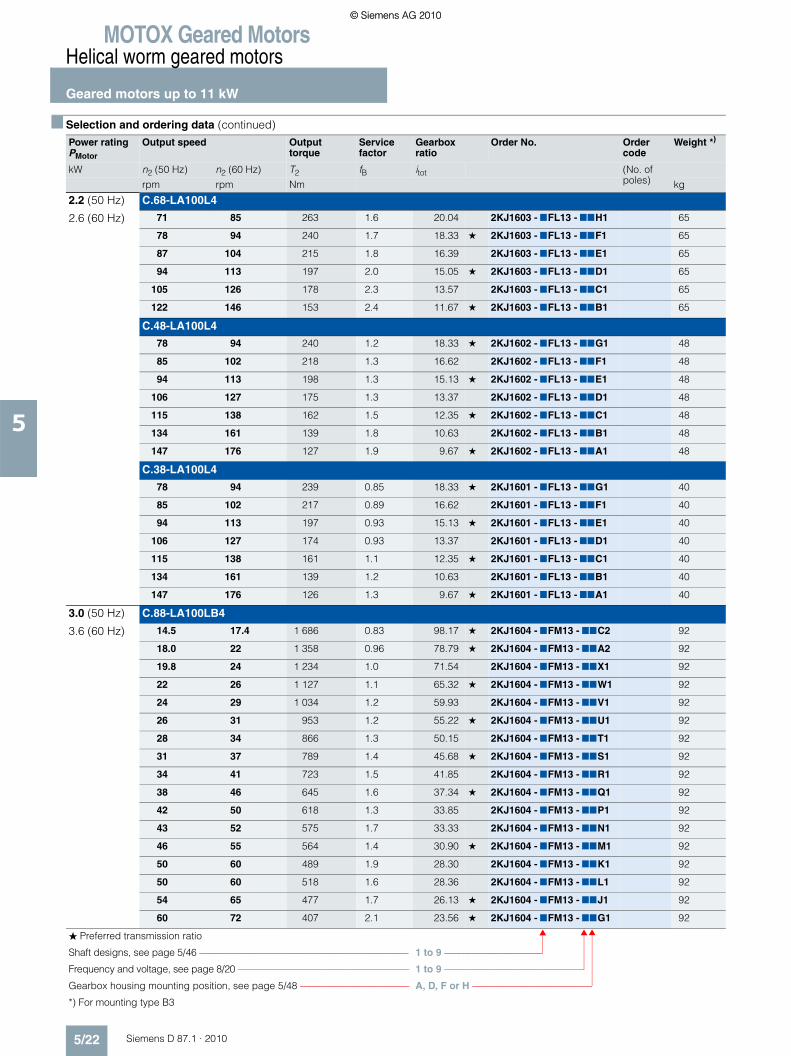
2.2 (50 Hz) C.68-LA100L4
2.6 (60 Hz) 71 85 263 1.6 20.04 2KJ1603 - 7FL13 - 77H1 65
78 94 240 1.7 18.33 ★ 2KJ1603 - 7FL13 - 77F1 65
87 104 215 1.8 16.39 2KJ1603 - 7FL13 - 77E1 65
94 113 197 2.0 15.05 ★ 2KJ1603 - 7FL13 - 77D1 65
105 126 178 2.3 13.57 2KJ1603 - 7FL13 - 77C1 65
122 146 153 2.4 11.67 ★ 2KJ1603 - 7FL13 - 77B1 65
C.48-LA100L4
78 94 240 1.2 18.33 ★ 2KJ1602 - 7FL13 - 77G1 48
85 102 218 1.3 16.62 2KJ1602 - 7FL13 - 77F1 48
94 113 198 1.3 15.13 ★ 2KJ1602 - 7FL13 - 77E1 48
106 127 175 1.3 13.37 2KJ1602 - 7FL13 - 77D1 48
115 138 162 1.5 12.35 ★ 2KJ1602 - 7FL13 - 77C1 48
134 161 139 1.8 10.63 2KJ1602 - 7FL13 - 77B1 48
147 176 127 1.9 9.67 ★ 2KJ1602 - 7FL13 - 77A1 48
C.38-LA100L4
78 94 239 0.85 18.33 ★ 2KJ1601 - 7FL13 - 77G1 40
85 102 217 0.89 16.62 2KJ1601 - 7FL13 - 77F1 40
94 113 197 0.93 15.13 ★ 2KJ1601 - 7FL13 - 77E1 40
106 127 174 0.93 13.37 2KJ1601 - 7FL13 - 77D1 40
115 138 161 1.1 12.35 ★ 2KJ1601 - 7FL13 - 77C1 40
134 161 139 1.2 10.63 2KJ1601 - 7FL13 - 77B1 40
147 176 126 1.3 9.67 ★ 2KJ1601 - 7FL13 - 77A1 40
3.0 (50 Hz) C.88-LA100LB4
3.6 (60 Hz) 14.5 17.4 1 686 0.83 98.17 ★ 2KJ1604 - 7FM13 - 77C2 92
18.0 22 1 358 0.96 78.79 ★ 2KJ1604 - 7FM13 - 77A2 92
19.8 24 1 234 1.0 71.54 2KJ1604 - 7FM13 - 77X1 92
22 26 1 127 1.1 65.32 ★ 2KJ1604 - 7FM13 - 77W1 92
24 29 1 034 1.2 59.93 2KJ1604 - 7FM13 - 77V1 92
26 31 953 1.2 55.22 ★ 2KJ1604 - 7FM13 - 77U1 92
28 34 866 1.3 50.15 2KJ1604 - 7FM13 - 77T1 92
31 37 789 1.4 45.68 ★ 2KJ1604 - 7FM13 - 77S1 92
34 41 723 1.5 41.85 2KJ1604 - 7FM13 - 77R1 92
38 46 645 1.6 37.34 ★ 2KJ1604 - 7FM13 - 77Q1 92
42 50 618 1.3 33.85 2KJ1604 - 7FM13 - 77P1 92
43 52 575 1.7 33.33 2KJ1604 - 7FM13 - 77N1 92
46 55 564 1.4 30.90 ★ 2KJ1604 - 7FM13 - 77M1 92
50 60 489 1.9 28.30 2KJ1604 - 7FM13 - 77K1 92
50 60 518 1.6 28.36 2KJ1604 - 7FM13 - 77L1 92
54 65 477 1.7 26.13 ★ 2KJ1604 - 7FM13 - 77J1 92
60 72 407 2.1 23.56 ★ 2KJ1604 - 7FM13 - 77G1 92
■ Selection and ordering data (continued)Power ratingPMotor
Output speed Output torque
Service factor
Gearbox ratio
Order No. Order code
Weight *)
kW n2 (50 Hz) n2 (60 Hz) T2 fB itot (No. of poles)rpm rpm Nm kg
� Preferred transmission ratio
Shaft designs, see page 5/46 ––––––––––––––––––––––––––––––––––––––––––– 1 to 9 –––––––––––––––––––––
Frequency and voltage, see page 8/20 –––––––––––––––––––––––––––––––––––– 1 to 9 –––––––––––––––––––––––––––––
Gearbox housing mounting position, see page 5/48 ––––––––––––––––––––––– A, D, F or H –––––––––––––––––––––––––
*) For mounting type B3
© Siemens AG 2010© Siemens AG 2010

MOTOX Geared MotorsHelical worm geared motors
Geared motors up to 11 kW
5/23Siemens D 87.1 · 2010
5
3.0 (50 Hz) C.88-LA100LB4
3.6 (60 Hz) 60 72 433 1.7 23.73 2KJ1604 - 7FM13 - 77H1 92
66 79 395 2.0 21.61 ★ 2KJ1604 - 7FM13 - 77F1 92
72 86 361 2.2 19.80 2KJ1604 - 7FM13 - 77E1 92
80 96 323 2.4 17.67 ★ 2KJ1604 - 7FM13 - 77D1 92
90 108 288 2.7 15.77 2KJ1604 - 7FM13 - 77C1 92
106 127 244 3.1 13.39 2KJ1604 - 7FM13 - 77B1 92
127 152 204 3.3 11.15 ★ 2KJ1604 - 7FM13 - 77A1 92
C.68-LA100LB4
34 41 727 0.81 41.35 2KJ1603 - 7FM13 - 77W1 65
38 46 659 0.87 37.50 ★ 2KJ1603 - 7FM13 - 77U1 65
42 50 601 0.92 34.17 2KJ1603 - 7FM13 - 77T1 65
45 54 550 0.98 31.25 ★ 2KJ1603 - 7FM13 - 77R1 65
51 61 492 1.10 27.94 2KJ1603 - 7FM13 - 77P1 65
53 64 480 0.83 26.89 ★ 2KJ1603 - 7FM13 - 77N1 65
55 66 451 1.10 25.66 ★ 2KJ1603 - 7FM13 - 77M1 65
58 70 433 0.91 24.26 2KJ1603 - 7FM13 - 77L1 65
61 73 407 1.2 23.13 2KJ1603 - 7FM13 - 77K1 65
64 77 393 1.1 22.00 ★ 2KJ1603 - 7FM13 - 77J1 65
71 85 350 1.3 19.89 ★ 2KJ1603 - 7FM13 - 77G1 65
71 85 358 1.2 20.04 2KJ1603 - 7FM13 - 77H1 65
78 94 327 1.3 18.33 ★ 2KJ1603 - 7FM13 - 77F1 65
87 104 293 1.3 16.39 2KJ1603 - 7FM13 - 77E1 65
94 113 269 1.5 15.05 ★ 2KJ1603 - 7FM13 - 77D1 65
105 126 242 1.7 13.57 2KJ1603 - 7FM13 - 77C1 65
122 146 208 1.8 11.67 ★ 2KJ1603 - 7FM13 - 77B1 65
C.48-LA100LB4
78 94 327 0.90 18.33 ★ 2KJ1602 - 7FM13 - 77G1 48
85 102 297 0.97 16.62 2KJ1602 - 7FM13 - 77F1 48
94 113 270 0.97 15.13 ★ 2KJ1602 - 7FM13 - 77E1 48
106 127 239 0.97 13.37 2KJ1602 - 7FM13 - 77D1 48
115 138 221 1.1 12.35 ★ 2KJ1602 - 7FM13 - 77C1 48
134 161 190 1.3 10.63 2KJ1602 - 7FM13 - 77B1 48
147 176 173 1.4 9.67 ★ 2KJ1602 - 7FM13 - 77A1 48
C.38-LA100LB4
134 161 189 0.91 10.63 2KJ1601 - 7FM13 - 77B1 40
147 176 172 0.97 9.67 ★ 2KJ1601 - 7FM13 - 77A1 40
4.0 (50 Hz) C.88-LA112MB4
4.8 (60 Hz) 22 26 1 482 0.82 65.32 ★ 2KJ1604 - 7GH13 - 77W1 99
24 29 1 360 0.87 59.93 2KJ1604 - 7GH13 - 77V1 99
26 31 1 253 0.92 55.22 ★ 2KJ1604 - 7GH13 - 77U1 99
■ Selection and ordering data (continued)Power ratingPMotor
Output speed Output torque
Service factor
Gearbox ratio
Order No. Order code
Weight *)
kW n2 (50 Hz) n2 (60 Hz) T2 fB itot (No. of poles)rpm rpm Nm kg
� Preferred transmission ratio
Shaft designs, see page 5/46 ––––––––––––––––––––––––––––––––––––––––––– 1 to 9 –––––––––––––––––––––
Frequency and voltage, see page 8/20 –––––––––––––––––––––––––––––––––––– 1 to 9 –––––––––––––––––––––––––––––
Gearbox housing mounting position, see page 5/48 ––––––––––––––––––––––– A, D, F or H –––––––––––––––––––––––––
*) For mounting type B3
© Siemens AG 2010© Siemens AG 2010

MOTOX Geared MotorsHelical worm geared motors
Geared motors up to 11 kW
5/24 Siemens D 87.1 · 2010
5
4.0 (50 Hz) C.88-LA112MB4
4.8 (60 Hz) 29 35 1 138 0.98 50.15 2KJ1604 - 7GH13 - 77T1 99
32 38 1 037 1.00 45.68 ★ 2KJ1604 - 7GH13 - 77S1 99
34 41 950 1.10 41.85 2KJ1604 - 7GH13 - 77R1 99
39 47 848 1.20 37.34 ★ 2KJ1604 - 7GH13 - 77Q1 99
42 50 812 0.99 33.85 2KJ1604 - 7GH13 - 77P1 99
43 52 757 1.3 33.33 2KJ1604 - 7GH13 - 77N1 99
47 56 742 1.1 30.90 ★ 2KJ1604 - 7GH13 - 77M1 99
51 61 642 1.4 28.30 2KJ1604 - 7GH13 - 77K1 99
51 61 681 1.2 28.36 2KJ1604 - 7GH13 - 77L1 99
55 66 627 1.3 26.13 ★ 2KJ1604 - 7GH13 - 77J1 99
61 73 535 1.6 23.56 ★ 2KJ1604 - 7GH13 - 77G1 99
61 73 570 1.3 23.73 2KJ1604 - 7GH13 - 77H1 99
67 80 519 1.5 21.61 ★ 2KJ1604 - 7GH13 - 77F1 99
73 88 475 1.7 19.80 2KJ1604 - 7GH13 - 77E1 99
82 98 424 1.8 17.67 ★ 2KJ1604 - 7GH13 - 77D1 99
91 109 379 2.0 15.77 2KJ1604 - 7GH13 - 77C1 99
108 130 321 2.4 13.39 2KJ1604 - 7GH13 - 77B1 99
129 155 268 2.5 11.15 ★ 2KJ1604 - 7GH13 - 77A1 99
C.68-LA112MB4
52 62 646 0.80 27.94 2KJ1603 - 7GH13 - 77P1 72
56 67 594 0.85 25.66 ★ 2KJ1603 - 7GH13 - 77M1 72
62 74 535 0.91 23.13 2KJ1603 - 7GH13 - 77K1 72
66 79 517 0.81 22.00 ★ 2KJ1603 - 7GH13 - 77J1 72
72 86 460 1.00 19.89 ★ 2KJ1603 - 7GH13 - 77G1 72
72 86 471 0.90 20.04 2KJ1603 - 7GH13 - 77H1 72
79 95 431 0.97 18.33 ★ 2KJ1603 - 7GH13 - 77F1 72
88 106 385 1.0 16.39 2KJ1603 - 7GH13 - 77E1 72
96 115 353 1.1 15.05 ★ 2KJ1603 - 7GH13 - 77D1 72
106 127 319 1.3 13.57 2KJ1603 - 7GH13 - 77C1 72
123 148 274 1.4 11.67 ★ 2KJ1603 - 7GH13 - 77B1 72
C.48-LA112MB4
117 140 290 0.84 12.35 ★ 2KJ1602 - 7GH13 - 77C1 55
135 162 250 1.0 10.63 2KJ1602 - 7GH13 - 77B1 55
149 179 227 1.1 9.67 ★ 2KJ1602 - 7GH13 - 77A1 55
5.5 (50 Hz) C.88-LA132SB4
6.6 (60 Hz) 35 42 1 293 0.81 41.85 2KJ1604 - 7HF13 - 77R1 109
39 47 1 153 0.88 37.34 ★ 2KJ1604 - 7HF13 - 77Q1 109
44 53 1 030 0.95 33.33 2KJ1604 - 7HF13 - 77N1 109
47 56 1 009 0.80 30.90 ★ 2KJ1604 - 7HF13 - 77M1 109
51 61 874 1.10 28.30 2KJ1604 - 7HF13 - 77K1 109
■ Selection and ordering data (continued)Power ratingPMotor
Output speed Output torque
Service factor
Gearbox ratio
Order No. Order code
Weight *)
kW n2 (50 Hz) n2 (60 Hz) T2 fB itot (No. of poles)rpm rpm Nm kg
� Preferred transmission ratio
Shaft designs, see page 5/46 ––––––––––––––––––––––––––––––––––––––––––– 1 to 9 –––––––––––––––––––––
Frequency and voltage, see page 8/20 –––––––––––––––––––––––––––––––––––– 1 to 9 –––––––––––––––––––––––––––––
Gearbox housing mounting position, see page 5/48 ––––––––––––––––––––––– A, D, F or H –––––––––––––––––––––––––
*) For mounting type B3
© Siemens AG 2010© Siemens AG 2010

MOTOX Geared MotorsHelical worm geared motors
Geared motors up to 11 kW
5/25Siemens D 87.1 · 2010
5
5.5 (50 Hz) C.88-LA132SB4
6.6 (60 Hz) 51 61 926 0.87 28.36 2KJ1604 - 7HF13 - 77L1 109
56 67 854 0.94 26.13 ★ 2KJ1604 - 7HF13 - 77J1 109
61 73 775 0.97 23.73 2KJ1604 - 7HF13 - 77H1 109
62 74 728 1.2 23.56 ★ 2KJ1604 - 7HF13 - 77G1 109
67 80 706 1.1 21.61 ★ 2KJ1604 - 7HF13 - 77F1 109
74 89 647 1.2 19.80 2KJ1604 - 7HF13 - 77E1 109
82 98 577 1.4 17.67 ★ 2KJ1604 - 7HF13 - 77D1 109
92 110 515 1.5 15.77 2KJ1604 - 7HF13 - 77C1 109
109 131 437 1.7 13.39 2KJ1604 - 7HF13 - 77B1 109
130 156 364 1.8 11.15 ★ 2KJ1604 - 7HF13 - 77A1 109
C.68-LA132SB4
97 116 481 0.82 15.05 ★ 2KJ1603 - 7HF13 - 77D1 82
107 128 434 0.95 13.57 2KJ1603 - 7HF13 - 77C1 82
125 150 373 1.0 11.67 ★ 2KJ1603 - 7HF13 - 77B1 82
7.5 (50 Hz) C.88-LA132M4
9.0 (60 Hz) 62 74 992 0.87 23.56 ★ 2KJ1604 - 7HH13 - 77G1 117
67 80 963 0.83 21.61 ★ 2KJ1604 - 7HH13 - 77F1 117
74 89 882 0.9 19.80 2KJ1604 - 7HH13 - 77E1 117
82 98 787 1.0 17.67 ★ 2KJ1604 - 7HH13 - 77D1 117
92 110 702 1.1 15.77 2KJ1604 - 7HH13 - 77C1 117
109 131 596 1.3 13.39 2KJ1604 - 7HH13 - 77B1 117
130 156 497 1.4 11.15 ★ 2KJ1604 - 7HH13 - 77A1 117
9.2 (50 Hz) C.88-LA132ZMP4
11.0 (60 Hz) 82 98 972 0.81 17.67 ★ 2KJ1604 - 7HT13 - 77D1 117
92 110 868 0.89 15.77 2KJ1604 - 7HT13 - 77C1 117
108 130 737 1.0 13.39 2KJ1604 - 7HT13 - 77B1 117
130 156 613 1.1 11.15 ★ 2KJ1604 - 7HT13 - 77A1 117
11.0 (50 Hz) C.88-LA160MB4
13.2 (60 Hz) 109 131 872 0.87 13.39 2KJ1604 - 7JP13 - 77B1 141
131 157 726 0.92 11.15 ★ 2KJ1604 - 7JP13 - 77A1 141
■ Selection and ordering data (continued)Power ratingPMotor
Output speed Output torque
Service factor
Gearbox ratio
Order No. Order code
Weight *)
kW n2 (50 Hz) n2 (60 Hz) T2 fB itot (No. of poles)rpm rpm Nm kg
� Preferred transmission ratio
Shaft designs, see page 5/46 ––––––––––––––––––––––––––––––––––––––––––– 1 to 9 –––––––––––––––––––––
Frequency and voltage, see page 8/20 –––––––––––––––––––––––––––––––––––– 1 to 9 –––––––––––––––––––––––––––––
Gearbox housing mounting position, see page 5/48 ––––––––––––––––––––––– A, D, F or H –––––––––––––––––––––––––
*) For mounting type B3
© Siemens AG 2010© Siemens AG 2010

MOTOX Geared MotorsHelical worm geared motors
Transmission ratios and maximum torques
5/26 Siemens D 87.1 · 2010
5
■ Selection and ordering data
Efficiency table C.28
Efficiency table C.28
Transmis-sion ratio
Ratio code
Output speed Output speed Output speed Size for motor and input units
nmot = 2 500 rpm nmot = 1750 rpm nmot = 1 450 rpm
itot Order No. 15th and 16th position
n2 T2 Pmot h n2 T2 Pmot h n2 T2 Pmot hrpm Nm kW % rpm Nm kW % rpm Nm kW % 63 71 80 90 100 112 132 160
372.00 P1 6.7 119 0.15 56 4.7 119 0.10 56 3.9 118 0.09 56 •303.36 N1 8.2 109 0.17 56 5.8 109 0.12 56 4.8 108 0.10 56 •248.00 M1 10.1 118 0.19 66 7.1 118 0.13 66 5.8 118 0.11 66 •202.24 L1 12.4 100 0.20 66 8.7 100 0.14 66 7.2 100 0.11 66 •155.00 K1 16.1 116 0.26 74 11.3 116 0.19 74 9.4 116 0.15 74 •126.40 J1 19.8 94 0.26 74 13.8 95 0.18 74 11.5 95 0.15 74 •93.00 H1 27.0 118 0.40 83 18.8 118 0.28 83 15.6 118 0.23 83 •75.84 G1 33.0 96 0.40 83 23.0 96 0.28 83 19.1 96 0.23 83 •62.00 F1 40.0 117 0.57 87 28.0 117 0.40 87 23.0 117 0.32 87 •50.56 E1 49.0 94 0.56 87 35.0 95 0.40 87 29.0 95 0.33 87 •46.50 D1 54.0 110 0.70 90 38.0 110 0.49 90 31.0 110 0.40 90 •37.92 C1 66.0 90 0.69 90 46.0 90 0.48 90 38.0 90 0.40 90 •31.00 B1 81.0 99 0.92 92 56.0 100 0.64 92 47.0 99 0.53 92 •25.28 A1 99.0 81 0.91 92 69.0 81 0.64 92 57.0 81 0.53 92 •
� Preferred transmission ratioIn the case of gearboxes of size 28, only possible with integrated motor or input unit KQ and KQS.
Transmis-sion ratio
Ratio code
Output speed Output speed Size for motor and input units
nmot = 1 150 rpm nmot = 950 rpm
itot Order No. 15th and 16th position
n2 T2 Pmot h n2 T2 Pmot hrpm Nm kW % rpm Nm kW % 63 71 80 90 100 112 132 160
372.00 P1 3.1 117 0.07 55 2.6 116 0.06 55 •303.36 N1 3.8 108 0.08 55 3.1 107 0.06 55 •248.00 M1 4.6 118 0.09 66 3.8 117 0.07 65 •202.24 L1 5.7 99 0.09 66 4.7 99 0.07 65 •155.00 K1 7.4 116 0.12 74 6.1 116 0.10 74 •126.40 J1 9.1 94 0.12 74 7.5 94 0.10 74 •93.00 H1 12.4 118 0.19 83 10.2 118 0.15 82 •75.84 G1 15.2 95 0.18 83 12.5 95 0.15 82 •62.00 F1 18.5 117 0.26 87 15.3 117 0.22 87 •50.56 E1 23.0 94 0.26 87 18.8 94 0.21 87 •46.50 D1 25.0 110 0.32 90 20.0 110 0.26 89 •37.92 C1 30.0 90 0.31 90 25.0 89 0.26 89 •31.00 B1 37.0 99 0.42 92 31.0 99 0.35 92 •25.28 A1 45.0 81 0.42 92 38.0 81 0.35 92 •
� Preferred transmission ratioIn the case of gearboxes of size 28, only possible with integrated motor or input unit KQ and KQS.
© Siemens AG 2010© Siemens AG 2010

MOTOX Geared MotorsHelical worm geared motors
Transmission ratios and maximum torques
5/27Siemens D 87.1 · 2010
5
■ Selection and ordering data (continued)
Efficiency table C.28
Transmis-sion ratio
Ratio code
Output speed Output speed Size for motor and input units
nmot = 850 rpm nmot = 700 rpm
itot Order No. 15th and 16th position
n2 T2 Pmot h n2 T2 Pmot hrpm Nm kW % rpm Nm kW % 63 71 80 90 100 112 132 160
372.00 P1 2.3 116 0.05 54 1.9 114 <0.05 54 •303.36 N1 2.8 106 0.06 54 2.3 104 <0.05 54 •248.00 M1 3.4 117 0.06 65 2.8 116 0.05 65 •202.24 L1 4.2 98 0.07 65 3.5 97 0.06 65 •155.00 K1 5.5 115 0.09 73 4.5 115 0.07 73 •126.40 J1 6.7 94 0.09 73 5.5 93 0.07 73 •93.00 H1 9.1 118 0.14 82 7.5 117 0.11 82 •75.84 G1 11.2 95 0.14 82 9.2 95 0.11 82 •62.00 F1 13.7 117 0.19 87 11.3 117 0.16 86 •50.56 E1 16.8 94 0.19 87 13.8 94 0.16 86 •46.50 D1 18.3 110 0.24 89 15.1 110 0.19 89 •37.92 C1 22.0 89 0.23 89 18.5 89 0.19 89 •31.00 B1 27.0 99 0.31 91 23.0 99 0.26 91 •25.28 A1 34.0 81 0.31 91 28.0 80 0.26 91 •
� Preferred transmission ratioIn the case of gearboxes of size 28, only possible with integrated motor or input unit KQ and KQS.
© Siemens AG 2010© Siemens AG 2010

MOTOX Geared MotorsHelical worm geared motors
Transmission ratios and maximum torques
5/28 Siemens D 87.1 · 2010
5
■ Selection and ordering data (continued)
Efficiency table C.38-D/Z28
Transmis-sion ratio
Ratio code
Output speed Output speed Size for motor and input units
nmot = 1 750 rpm nmot = 1 450 rpm
itot Order No. 15th and 16th position
n2 T2 Pmot h n2 T2 Pmot hrpm Nm kW % rpm Nm kW % 63 71 80 90 100 112 132 160
23 503 N1 0.07 222 <0.06 45 0.06 222 <0.06 45 •20 276 M1 0.09 222 <0.06 45 0.07 222 <0.06 45 •17 420 L1 0.10 222 <0.06 45 0.08 222 <0.06 45 •16 037 K1 0.11 222 <0.06 45 0.09 222 <0.06 45 •14 579 J1 0.12 222 <0.06 45 0.10 222 <0.06 45 •12 904 H1 0.14 222 <0.06 45 0.11 222 <0.06 45 •10 808 G1 0.16 222 <0.06 45 0.13 222 <0.06 45 •9 216 F1 0.19 222 <0.06 46 0.16 222 <0.06 45 •7 833 E1 0.22 222 <0.06 46 0.19 222 <0.06 46 •6 807 D1 0.26 222 <0.06 46 0.21 222 <0.06 46 •5 925 C1 0.30 222 <0.06 46 0.24 222 <0.06 46 •5 345 B1 0.33 222 <0.06 46 0.27 222 <0.06 46 •4 717 A1 0.37 222 <0.06 46 0.31 222 <0.06 46 •4 222 B2 0.41 222 <0.06 47 0.34 222 <0.06 46 •3 749 A2 0.47 222 <0.06 47 0.39 222 <0.06 46 •3 286 X1 0.53 222 <0.06 47 0.44 222 <0.06 47 •2 941 W1 0.60 222 <0.06 47 0.49 222 <0.06 47 •2 610 V1 0.67 222 <0.06 48 0.56 222 <0.06 47 •2 288 U1 0.76 223 <0.06 48 0.63 222 <0.06 47 •2 011 T1 0.87 223 <0.06 48 0.72 222 <0.06 48 •1 817 S1 0.96 223 <0.06 49 0.80 223 <0.06 48 •1 583 R1 1.11 223 <0.06 49 0.92 223 <0.06 49 •1 422 Q1 1.23 223 <0.06 50 1.02 223 <0.06 49 •1 284 P1 1.36 223 0.06 50 1.13 223 <0.06 49 •1 164 N1 1.50 223 0.07 51 1.25 223 <0.06 50 •1 059 M1 1.65 223 0.08 51 1.37 223 0.06 50 •
937 L1 1.87 223 0.08 52 1.55 223 0.07 51 •865 K1 2.02 223 0.09 53 1.68 223 0.08 51 •745 J1 2.35 223 0.10 54 1.95 223 0.09 52 •677 H1 2.59 224 0.11 54 2.14 223 0.09 53 •615 G1 2.84 224 0.12 55 2.36 223 0.10 54 •558 F1 3.14 224 0.13 56 2.60 224 0.11 55 •508 E1 3.45 224 0.14 57 2.86 224 0.12 55 •449 D1 3.90 224 0.16 58 3.23 224 0.13 56 •414 C1 4.22 225 0.17 59 3.50 224 0.14 57 •357 B1 4.90 225 0.19 60 4.06 225 0.16 58 •324 A1 5.40 225 0.21 61 4.47 225 0.18 59 •
� Preferred transmission ratioIn the case of gearboxes of size 28, only possible with integrated motor or input unit KQ and KQS.
© Siemens AG 2010© Siemens AG 2010

MOTOX Geared MotorsHelical worm geared motors
Transmission ratios and maximum torques
5/29Siemens D 87.1 · 2010
5
■ Selection and ordering data (continued)
Efficiency table C.38
Transmis-sion ratio
Ratio code
Output speed Output speed Output speed Size for motor and input units
nmot = 1 750 rpm nmot = 1 450 rpm nmot = 1 150 rpm
itot Order No. 15th and 16th position
n2 T2 Pmot h n2 T2 Pmot h n2 T2 Pmot hrpm Nm kW % rpm Nm kW % rpm Nm kW % 63 71 80 90 100 112 132 160
320.67 ★ K2 5.5 225 0.21 62 4.5 225 0.18 60 3.6 224 0.15 58 • • •
284.70 J2 6.1 226 0.23 63 5.1 225 0.20 62 4.0 224 0.16 59 • • •249.60 ★ H2 7.0 226 0.26 64 5.8 226 0.22 63 4.6 225 0.18 61 • • • •
223.36 G2 7.8 227 0.28 65 6.5 226 0.24 64 5.1 225 0.20 62 • • • •198.25 ★ F2 8.8 227 0.32 66 7.3 226 0.27 65 5.8 225 0.22 63 • • • •
173.73 E2 10.1 228 0.36 67 8.3 227 0.30 66 6.6 226 0.24 64 • • • •152.75 ★ D2 11.5 228 0.41 68 9.5 227 0.34 67 7.5 226 0.27 65 • • • •
138.00 C2 12.7 229 0.45 68 10.5 228 0.37 67 8.3 227 0.30 66 • • • •120.25 ★ B2 14.6 230 0.51 68 12.1 229 0.43 68 9.6 228 0.34 67 • • • •
108.00 A2 16.2 226 0.56 69 13.4 229 0.47 68 10.6 228 0.38 67 • • • •97.50 ★ X1 17.9 219 0.60 69 14.9 230 0.53 68 11.8 229 0.42 68 • • • • •
88.40 W1 19.8 211 0.64 69 16.4 224 0.56 69 13.0 229 0.46 68 • • • • •80.44 ★ V1 22.0 203 0.68 69 18.0 217 0.60 69 14.3 230 0.50 68 • • • • •
71.12 U1 25.0 195 0.74 69 20.0 210 0.64 69 16.2 225 0.56 69 • • • • •65.68 ★ T1 27.0 191 0.78 69 22.0 204 0.68 69 17.5 220 0.59 69 • • • • •
60.30 ★ S1 29.0 204 0.71 87 24.0 202 0.59 87 19.1 199 0.47 85 • • •
53.53 R1 33.0 245 0.96 88 27.0 243 0.79 87 21.0 239 0.61 86 • • •46.93 ★ Q1 37.0 232 1.02 88 31.0 231 0.85 88 25.0 228 0.69 87 • • • •
42.00 P1 42.0 222 1.10 89 35.0 220 0.92 88 27.0 218 0.71 87 • • • •37.28 ★ N1 47.0 232 1.28 89 39.0 231 1.07 89 31.0 229 0.85 88 • • • •
32.67 M1 54.0 192 1.22 89 44.0 192 0.99 89 35.0 190 0.79 88 • • • •28.72 ★ L1 61.0 208 1.49 89 50.0 207 1.22 89 40.0 206 0.97 89 • • • •
25.95 K1 67.0 209 1.64 89 56.0 208 1.37 89 44.0 207 1.08 89 • • • •22.61 ★ J1 77.0 206 1.86 89 64.0 206 1.55 89 51.0 205 1.23 89 • • • •
20.31 H1 86.0 196 1.98 89 71.0 196 1.63 89 57.0 196 1.31 89 • • • •18.33 ★ G1 95.0 199 2.21 89 79.0 206 1.91 89 63.0 206 1.52 89 • • • • •
16.62 F1 105.0 191 2.34 89 87.0 196 2.00 89 69.0 196 1.59 89 • • • • •15.13 ★ E1 116.0 183 2.49 89 96.0 187 2.10 89 76.0 187 1.66 89 • • • • •
13.37 D1 131.0 165 2.53 89 108.0 165 2.09 89 86.0 165 1.66 89 • • • • •12.35 ★ C1 142.0 169 2.81 89 117.0 172 2.36 89 93.0 172 1.88 89 • • • • •
10.63 B1 165.0 155 3.00 89 136.0 173 2.76 89 108.0 183 2.31 89 • • • • •9.67 ★ A1 181.0 141 3.00 89 150.0 170 3.00 89 119.0 176 2.46 89 • • • • •
� Preferred transmission ratioIn the case of gearboxes of size 28, only possible with integrated motor or input unit KQ and KQS.
© Siemens AG 2010© Siemens AG 2010

MOTOX Geared MotorsHelical worm geared motors
Transmission ratios and maximum torques
5/30 Siemens D 87.1 · 2010
5
■ Selection and ordering data (continued)
Efficiency table C.38
Transmis-sion ratio
Ratio code
Output speed Output speed Output speed Size for motor and input units
nmot = 950 rpm nmot = 850 rpm nmot = 700 rpm
itot Order No. 15th and 16th position
n2 T2 Pmot h n2 T2 Pmot h n2 T2 Pmot hrpm Nm kW % rpm Nm kW % rpm Nm kW % 63 71 80 90 100 112 132 160
320.67 ★ K2 3.0 224 0.12 56 2.7 224 0.11 56 2.2 223 0.10 54 • • •
284.70 J2 3.3 224 0.13 58 3.0 224 0.12 57 2.5 224 0.11 55 • • •249.60 ★ H2 3.8 224 0.15 59 3.4 224 0.14 58 2.8 224 0.12 56 • • • •
223.36 G2 4.3 225 0.17 60 3.8 224 0.15 59 3.1 224 0.13 57 • • • •198.25 ★ F2 4.8 225 0.19 61 4.3 225 0.17 60 3.5 224 0.14 58 • • • •
173.73 E2 5.5 225 0.21 62 4.9 225 0.19 61 4.0 224 0.16 59 • • • •152.75 ★ D2 6.2 226 0.23 63 5.6 225 0.21 62 4.6 225 0.18 61 • • • •
138.00 C2 6.9 226 0.25 64 6.2 226 0.23 63 5.1 225 0.20 62 • • • •120.25 ★ B2 7.9 227 0.29 65 7.1 226 0.26 65 5.8 226 0.22 63 • • • •
108.00 A2 8.8 227 0.32 66 7.9 227 0.29 65 6.5 226 0.24 64 • • • •97.50 ★ X1 9.7 228 0.35 67 8.7 227 0.31 66 7.2 226 0.26 65 • • • • •
88.40 W1 10.7 228 0.38 67 9.6 228 0.34 67 7.9 227 0.29 65 • • • • •80.44 ★ V1 11.8 229 0.42 68 10.6 228 0.38 67 8.7 227 0.31 66 • • • • •
71.12 U1 13.4 229 0.47 68 12.0 229 0.42 68 9.8 228 0.35 67 • • • • •65.68 ★ T1 14.5 230 0.51 68 12.9 229 0.46 68 10.7 228 0.38 67 • • • • •
60.30 ★ S1 15.8 196 0.39 84 14.1 195 0.34 84 11.6 192 0.28 82 • • •
53.53 R1 17.7 236 0.52 85 15.9 234 0.46 84 13.1 231 0.38 83 • • •46.93 ★ Q1 20.0 225 0.55 86 18.1 223 0.50 85 14.9 220 0.41 84 • • • •
42.00 P1 23.0 216 0.60 86 20.0 214 0.52 86 16.7 211 0.44 85 • • • •37.28 ★ N1 25.0 227 0.68 87 23.0 225 0.63 86 18.8 222 0.51 85 • • • •
32.67 M1 29.0 189 0.65 87 26.0 188 0.59 87 21.0 185 0.47 86 • • • •28.72 ★ L1 33.0 205 0.80 88 30.0 204 0.73 88 24.0 202 0.58 87 • • • •
25.95 K1 37.0 206 0.90 88 33.0 205 0.81 88 27.0 204 0.66 87 • • • •22.61 ★ J1 42.0 205 1.01 89 38.0 204 0.92 88 31.0 202 0.75 88 • • • •
20.31 H1 47.0 195 1.08 89 42.0 195 0.96 89 34.0 193 0.78 88 • • • •18.33 ★ G1 52.0 206 1.26 89 46.0 205 1.11 89 38.0 204 0.92 88 • • • • •
16.62 F1 57.0 196 1.31 89 51.0 195 1.17 89 42.0 195 0.96 89 • • • • •15.13 ★ E1 63.0 186 1.38 89 56.0 186 1.22 89 46.0 186 1.01 89 • • • • •
13.37 D1 71.0 165 1.37 89 64.0 165 1.24 89 52.0 164 1.00 89 • • • • •12.35 ★ C1 77.0 172 1.55 89 69.0 172 1.39 89 57.0 172 1.15 89 • • • • •
10.63 B1 89.0 183 1.90 89 80.0 183 1.71 89 66.0 182 1.41 89 • • • • •9.67 ★ A1 98.0 176 2.02 89 88.0 176 1.82 89 72.0 176 1.49 89 • • • • •
� Preferred transmission ratioIn the case of gearboxes of size 28, only possible with integrated motor or input unit KQ and KQS.
© Siemens AG 2010© Siemens AG 2010

MOTOX Geared MotorsHelical worm geared motors
Transmission ratios and maximum torques
5/31Siemens D 87.1 · 2010
5
■ Selection and ordering data (continued)
Efficiency table C.38
Transmis-sion ratio
Ratio code
Output speed Output speed Output speed Size for motor and input units
nmot = 500 rpm nmot = 250 rpm nmot = 10 rpm
itot Order No. 15th and 16th position
n2 T2 Pmot h n2 T2 Pmot h n2 T2 Pmot hrpm Nm kW % rpm Nm kW % rpm Nm kW % 63 71 80 90 100 112 132 160
320.67 ★ K2 1.6 223 0.07 52 0.78 223 <0.05 49 0.031 222 <0.05 46 • • •
284.70 J2 1.8 223 0.08 53 0.88 223 <0.05 49 0.035 222 <0.05 46 • • •249.60 ★ H2 2.0 223 0.09 53 1.00 223 <0.05 50 0.040 222 <0.05 46 • • • •
223.36 G2 2.2 223 0.09 54 1.10 223 0.05 50 0.045 222 <0.05 46 • • • •198.25 ★ F2 2.5 224 0.11 55 1.30 223 0.06 51 0.050 222 <0.05 46 • • • •
173.73 E2 2.9 224 0.12 56 1.40 223 0.06 51 0.058 222 <0.05 46 • • • •152.75 ★ D2 3.3 224 0.13 57 1.60 223 0.07 52 0.065 222 <0.05 46 • • • •
138.00 C2 3.6 224 0.15 58 1.80 223 0.08 53 0.072 222 <0.05 46 • • • •120.25 ★ B2 4.2 225 0.17 60 2.10 223 0.09 54 0.083 222 <0.05 46 • • • •
108.00 A2 4.6 225 0.18 61 2.30 223 0.10 54 0.093 222 <0.05 46 • • • •97.50 ★ X1 5.1 225 0.20 62 2.60 224 0.11 55 0.100 222 <0.05 46 • • • • •
88.40 W1 5.7 225 0.22 63 2.80 224 0.12 56 0.110 222 <0.05 46 • • • • •80.44 ★ V1 6.2 226 0.23 63 3.10 224 0.13 57 0.120 222 <0.05 46 • • • • •
71.12 U1 7.0 226 0.26 64 3.50 224 0.14 58 0.140 222 <0.05 46 • • • • •65.68 ★ T1 7.6 226 0.28 65 3.80 224 0.15 59 0.150 222 <0.05 46 • • • • •
60.30 ★ S1 8.3 188 0.20 80 4.10 181 0.10 78 0.170 173 <0.05 74 • • •
53.53 R1 9.3 226 0.27 81 4.70 217 0.14 78 0.190 206 <0.05 74 • • •46.93 ★ Q1 10.7 215 0.29 82 5.30 206 0.15 78 0.210 194 <0.05 74 • • • •
42.00 P1 11.9 206 0.31 82 6.00 197 0.16 79 0.240 185 <0.05 74 • • • •37.28 ★ N1 13.4 217 0.37 83 6.70 207 0.18 79 0.270 193 <0.05 74 • • • •
32.67 M1 15.3 181 0.35 84 7.70 173 0.17 80 0.310 160 <0.05 74 • • • •28.72 ★ L1 17.4 197 0.42 85 8.70 188 0.21 81 0.350 172 <0.05 74 • • • •
25.95 K1 19.3 199 0.47 85 9.60 190 0.23 81 0.390 173 <0.05 74 • • • •22.61 ★ J1 22.0 199 0.53 86 11.10 189 0.27 82 0.440 171 <0.05 74 • • • •
20.31 H1 25.0 190 0.57 87 12.30 181 0.28 83 0.490 163 <0.05 74 • • • •18.33 ★ G1 27.0 201 0.65 87 13.60 192 0.33 83 0.550 172 <0.05 74 • • • • •
16.62 F1 30.0 192 0.69 88 15.00 184 0.34 84 0.600 163 <0.05 74 • • • • •15.13 ★ E1 33.0 184 0.72 88 16.50 176 0.36 84 0.660 155 <0.05 74 • • • • •
13.37 D1 37.0 163 0.71 88 18.70 157 0.36 85 0.750 138 <0.05 75 • • • • •12.35 ★ C1 40.0 171 0.81 89 20.00 165 0.40 86 0.810 144 <0.05 75 • • • • •
10.63 B1 47.0 182 1.00 89 24.00 177 0.51 86 0.940 153 <0.05 75 • • • • •9.67 ★ A1 52.0 176 1.07 89 26.00 171 0.54 87 1.000 147 <0.05 75 • • • • •
� Preferred transmission ratioIn the case of gearboxes of size 28, only possible with integrated motor or input unit KQ and KQS.
© Siemens AG 2010© Siemens AG 2010

MOTOX Geared MotorsHelical worm geared motors
Transmission ratios and maximum torques
5/32 Siemens D 87.1 · 2010
5
■ Selection and ordering data (continued)
Efficiency table C.48-D/Z28
Transmis-sion ratio
Ratio code
Output speed Output speed Size for motor and input units
nmot = 1 750 rpm nmot = 1 450 rpm
itot Order No. 15th and 16th position
n2 T2 Pmot h n2 T2 Pmot hrpm Nm kW % rpm Nm kW % 63 71 80 90 100 112 132 160
23 503 N1 0.07 364 <0.06 47 0.06 364 <0.06 47 •20 276 M1 0.09 364 <0.06 47 0.07 364 <0.06 47 •17 420 L1 0.10 364 <0.06 47 0.08 364 <0.06 47 •16 037 K1 0.11 364 <0.06 47 0.09 364 <0.06 47 •14 579 J1 0.12 364 <0.06 47 0.10 364 <0.06 47 •12 904 H1 0.14 364 <0.06 47 0.11 364 <0.06 47 •10 808 G1 0.16 364 <0.06 47 0.13 364 <0.06 47 •9 216 F1 0.19 364 <0.06 47 0.16 364 <0.06 47 •7 833 E1 0.22 364 <0.06 48 0.19 364 <0.06 47 •6 807 D1 0.26 364 <0.06 48 0.21 364 <0.06 47 •5 925 C1 0.30 364 <0.06 48 0.24 364 <0.06 48 •5 345 B1 0.33 364 <0.06 48 0.27 364 <0.06 48 •4 717 A1 0.37 364 <0.06 48 0.31 364 <0.06 48 •4 222 B2 0.41 364 <0.06 48 0.34 364 <0.06 48 •3 749 A2 0.47 364 <0.06 49 0.39 364 <0.06 48 •3 286 X1 0.53 364 <0.06 49 0.44 364 <0.06 49 •2 941 W1 0.60 364 <0.06 49 0.49 364 <0.06 49 •2 610 V1 0.67 364 <0.06 50 0.56 364 <0.06 49 •2 288 U1 0.76 365 <0.06 50 0.63 364 <0.06 49 •2 011 T1 0.87 365 0.07 51 0.72 364 <0.06 50 •1 817 S1 0.96 365 0.07 51 0.80 365 0.06 50 •1 583 R1 1.11 365 0.08 52 0.92 365 0.07 51 •1 422 Q1 1.23 365 0.09 52 1.02 365 0.08 51 •1 284 P1 1.36 365 0.10 53 1.13 365 0.08 52 •1 164 N1 1.50 365 0.11 53 1.25 365 0.09 52 •1 059 M1 1.65 366 0.12 54 1.37 365 0.10 53 •
937 L1 1.87 366 0.13 55 1.55 365 0.11 53 •865 K1 2.02 366 0.14 55 1.68 366 0.12 54 •745 J1 2.35 366 0.16 56 1.95 366 0.14 55 •677 H1 2.59 367 0.17 57 2.14 366 0.15 56 •615 G1 2.84 367 0.19 58 2.36 366 0.16 57 •558 F1 3.14 367 0.20 59 2.60 367 0.17 57 •508 E1 3.45 368 0.22 60 2.86 367 0.19 58 •449 D1 3.90 368 0.25 61 3.23 367 0.21 59 •414 C1 4.22 368 0.26 62 3.50 368 0.22 60 •357 B1 4.90 369 0.30 64 4.06 368 0.25 62 •324 A1 5.40 370 0.32 64 4.47 369 0.28 63 •
� Preferred transmission ratioIn the case of gearboxes of size 28, only possible with integrated motor or input unit KQ and KQS.
© Siemens AG 2010© Siemens AG 2010
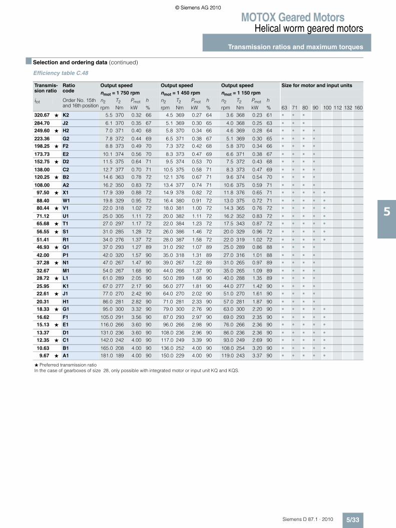
MOTOX Geared MotorsHelical worm geared motors
Transmission ratios and maximum torques
5/33Siemens D 87.1 · 2010
5
■ Selection and ordering data (continued)
Efficiency table C.48
Transmis-sion ratio
Ratio code
Output speed Output speed Output speed Size for motor and input units
nmot = 1 750 rpm nmot = 1 450 rpm nmot = 1 150 rpm
itot Order No. 15th and 16th position
n2 T2 Pmot h n2 T2 Pmot h n2 T2 Pmot hrpm Nm kW % rpm Nm kW % rpm Nm kW % 63 71 80 90 100 112 132 160
320.67 ★ K2 5.5 370 0.32 66 4.5 369 0.27 64 3.6 368 0.23 61 • • •
284.70 J2 6.1 370 0.35 67 5.1 369 0.30 65 4.0 368 0.25 63 • • •249.60 ★ H2 7.0 371 0.40 68 5.8 370 0.34 66 4.6 369 0.28 64 • • • •
223.36 G2 7.8 372 0.44 69 6.5 371 0.38 67 5.1 369 0.30 65 • • • •198.25 ★ F2 8.8 373 0.49 70 7.3 372 0.42 68 5.8 370 0.34 66 • • • •
173.73 E2 10.1 374 0.56 70 8.3 373 0.47 69 6.6 371 0.38 67 • • • •152.75 ★ D2 11.5 375 0.64 71 9.5 374 0.53 70 7.5 372 0.43 68 • • • •
138.00 C2 12.7 377 0.70 71 10.5 375 0.58 71 8.3 373 0.47 69 • • • •120.25 ★ B2 14.6 363 0.78 72 12.1 376 0.67 71 9.6 374 0.54 70 • • • •
108.00 A2 16.2 350 0.83 72 13.4 377 0.74 71 10.6 375 0.59 71 • • • •97.50 ★ X1 17.9 339 0.88 72 14.9 378 0.82 72 11.8 376 0.65 71 • • • • •
88.40 W1 19.8 329 0.95 72 16.4 380 0.91 72 13.0 375 0.72 71 • • • • •80.44 ★ V1 22.0 318 1.02 72 18.0 381 1.00 72 14.3 365 0.76 72 • • • • •
71.12 U1 25.0 305 1.11 72 20.0 382 1.11 72 16.2 352 0.83 72 • • • • •65.68 ★ T1 27.0 297 1.17 72 22.0 384 1.23 72 17.5 343 0.87 72 • • • • •
56.55 ★ S1 31.0 285 1.28 72 26.0 386 1.46 72 20.0 329 0.96 72 • • • • •
51.41 R1 34.0 276 1.37 72 28.0 387 1.58 72 22.0 319 1.02 72 • • • • •46.93 ★ Q1 37.0 293 1.27 89 31.0 292 1.07 89 25.0 289 0.86 88 • • • •
42.00 P1 42.0 320 1.57 90 35.0 318 1.31 89 27.0 316 1.01 88 • • • •37.28 ★ N1 47.0 267 1.47 90 39.0 267 1.22 89 31.0 265 0.97 89 • • • •
32.67 M1 54.0 267 1.68 90 44.0 266 1.37 90 35.0 265 1.09 89 • • • •28.72 ★ L1 61.0 289 2.05 90 50.0 289 1.68 90 40.0 288 1.35 89 • • • •
25.95 K1 67.0 277 2.17 90 56.0 277 1.81 90 44.0 277 1.42 90 • • • •22.61 ★ J1 77.0 270 2.42 90 64.0 270 2.02 90 51.0 270 1.61 90 • • • •
20.31 H1 86.0 281 2.82 90 71.0 281 2.33 90 57.0 281 1.87 90 • • • •18.33 ★ G1 95.0 300 3.32 90 79.0 300 2.76 90 63.0 300 2.20 90 • • • • •
16.62 F1 105.0 291 3.56 90 87.0 293 2.97 90 69.0 293 2.35 90 • • • • •15.13 ★ E1 116.0 266 3.60 90 96.0 266 2.98 90 76.0 266 2.36 90 • • • • •
13.37 D1 131.0 236 3.60 90 108.0 236 2.96 90 86.0 236 2.36 90 • • • • •12.35 ★ C1 142.0 242 4.00 90 117.0 249 3.39 90 93.0 249 2.69 90 • • • • •
10.63 B1 165.0 208 4.00 90 136.0 252 4.00 90 108.0 254 3.20 90 • • • • •9.67 ★ A1 181.0 189 4.00 90 150.0 229 4.00 90 119.0 243 3.37 90 • • • • •
� Preferred transmission ratioIn the case of gearboxes of size 28, only possible with integrated motor or input unit KQ and KQS.
© Siemens AG 2010© Siemens AG 2010

MOTOX Geared MotorsHelical worm geared motors
Transmission ratios and maximum torques
5/34 Siemens D 87.1 · 2010
5
■ Selection and ordering data (continued)
Efficiency table C.48
Transmis-sion ratio
Ratio code
Output speed Output speed Output speed Size for motor and input units
nmot = 950 rpm nmot = 850 rpm nmot = 750 rpm
itot Order No. 15th and 16th position
n2 T2 Pmot h n2 T2 Pmot h n2 T2 Pmot hrpm Nm kW % rpm Nm kW % rpm Nm kW % 63 71 80 90 100 112 132 160
320.67 ★ K2 3.0 367 0.19 59 2.7 367 0.18 58 2.2 366 0.15 57 • • •
284.70 J2 3.3 367 0.21 61 3.0 367 0.19 59 2.5 366 0.17 58 • • •249.60 ★ H2 3.8 368 0.24 62 3.4 368 0.22 61 2.8 367 0.18 59 • • • •
223.36 G2 4.3 368 0.26 63 3.8 368 0.24 62 3.1 367 0.20 60 • • • •198.25 ★ F2 4.8 369 0.29 64 4.3 368 0.26 63 3.5 368 0.22 61 • • • •
173.73 E2 5.5 370 0.32 66 4.9 369 0.29 64 4.0 368 0.25 62 • • • •152.75 ★ D2 6.2 370 0.36 67 5.6 370 0.33 66 4.6 369 0.28 64 • • • •
138.00 C2 6.9 371 0.40 68 6.2 370 0.36 67 5.1 369 0.30 65 • • • •120.25 ★ B2 7.9 372 0.45 69 7.1 371 0.41 68 5.8 370 0.34 66 • • • •
108.00 A2 8.8 373 0.49 70 7.9 372 0.45 69 6.5 371 0.38 67 • • • •97.50 ★ X1 9.7 374 0.54 70 8.7 373 0.49 69 7.2 371 0.41 68 • • • • •
88.40 W1 10.7 375 0.59 71 9.6 374 0.54 70 7.9 372 0.45 69 • • • • •80.44 ★ V1 11.8 376 0.65 71 10.6 375 0.59 71 8.7 373 0.49 69 • • • • •
71.12 U1 13.4 373 0.73 71 12.0 376 0.66 71 9.8 374 0.55 70 • • • • •65.68 ★ T1 14.5 363 0.77 72 12.9 377 0.71 71 10.7 375 0.59 71 • • • • •
56.55 ★ S1 16.8 348 0.85 72 15.0 361 0.79 72 12.4 376 0.69 71 • • • • •
51.41 R1 18.5 338 0.91 72 16.5 350 0.84 72 13.6 372 0.74 71 • • • • •46.93 ★ Q1 20.0 286 0.69 87 18.1 284 0.62 86 14.9 280 0.51 85 • • • •
42.00 P1 23.0 313 0.86 88 20.0 311 0.75 87 16.7 306 0.62 86 • • • •37.28 ★ N1 25.0 263 0.78 88 23.0 261 0.72 90 18.8 258 0.59 87 • • • •
32.67 M1 29.0 263 0.90 89 26.0 262 0.81 88 21.0 259 0.65 87 • • • •28.72 ★ L1 33.0 286 1.11 89 30.0 285 1.01 89 24.0 283 0.81 88 • • • •
25.95 K1 37.0 276 1.20 89 33.0 275 1.07 89 27.0 273 0.87 88 • • • •22.61 ★ J1 42.0 269 1.32 90 38.0 269 1.20 89 31.0 267 0.98 89 • • • •
20.31 H1 47.0 280 1.54 90 42.0 280 1.38 90 34.0 279 1.11 89 • • • •18.33 ★ G1 52.0 299 1.82 90 46.0 299 1.61 90 38.0 298 1.33 89 • • • • •
16.62 F1 57.0 293 1.94 90 51.0 292 1.74 90 42.0 292 1.43 90 • • • • •15.13 ★ E1 63.0 266 1.96 90 56.0 266 1.74 90 46.0 266 1.43 90 • • • • •
13.37 D1 71.0 235 1.95 90 64.0 235 1.76 90 52.0 235 1.43 90 • • • • •12.35 ★ C1 77.0 249 2.23 90 69.0 249 2.00 90 57.0 248 1.65 90 • • • • •
10.63 B1 89.0 254 2.64 90 80.0 254 2.37 90 66.0 254 1.95 90 • • • • •9.67 ★ A1 98.0 243 2.78 90 88.0 243 2.49 90 72.0 243 2.04 90 • • • • •
� Preferred transmission ratioIn the case of gearboxes of size 28, only possible with integrated motor or input unit KQ and KQS.
© Siemens AG 2010© Siemens AG 2010

MOTOX Geared MotorsHelical worm geared motors
Transmission ratios and maximum torques
5/35Siemens D 87.1 · 2010
5
■ Selection and ordering data (continued)
Efficiency table C.48
Transmis-sion ratio
Ratio code
Output speed Output speed Output speed Size for motor and input units
nmot = 500 rpm nmot = 250 rpm nmot = 10 rpm
itot Order No. 15th and 16th position
n2 T2 Pmot h n2 T2 Pmot h n2 T2 Pmot hrpm Nm kW % rpm Nm kW % rpm Nm kW % 63 71 80 90 100 112 132 160
320.67 ★ K2 1.6 365 0.11 54 0.78 365 0.06 51 0.031 364 <0.05 47 • • •
284.70 J2 1.8 366 0.13 55 0.88 365 0.07 51 0.035 364 <0.05 47 • • •249.60 ★ H2 2.0 366 0.14 56 1.00 365 0.07 52 0.040 364 <0.05 47 • • • •
223.36 G2 2.2 366 0.15 57 1.10 365 0.08 52 0.045 364 <0.05 47 • • • •198.25 ★ F2 2.5 367 0.17 58 1.30 365 0.09 53 0.050 364 <0.05 47 • • • •
173.73 E2 2.9 367 0.19 59 1.40 365 0.10 54 0.058 364 <0.05 47 • • • •152.75 ★ D2 3.3 367 0.21 60 1.60 366 0.11 55 0.065 364 <0.05 47 • • • •
138.00 C2 3.6 368 0.23 61 1.80 366 0.12 55 0.072 364 <0.05 47 • • • •120.25 ★ B2 4.2 368 0.26 63 2.10 366 0.14 56 0.083 364 <0.05 48 • • • •
108.00 A2 4.6 369 0.28 64 2.30 366 0.15 57 0.093 364 <0.05 48 • • • •97.50 ★ X1 5.1 369 0.30 65 2.60 367 0.17 58 0.100 364 <0.05 48 • • • • •
88.40 W1 5.7 370 0.33 66 2.80 367 0.18 59 0.110 364 <0.05 48 • • • • •80.44 ★ V1 6.2 370 0.36 67 3.10 367 0.20 60 0.120 364 <0.05 48 • • • • •
71.12 U1 7.0 371 0.40 68 3.50 368 0.22 61 0.140 364 <0.05 48 • • • • •65.68 ★ T1 7.6 372 0.43 69 3.80 368 0.24 62 0.150 364 <0.05 48 • • • • •
56.55 ★ S1 8.8 373 0.49 70 4.40 369 0.27 63 0.180 364 <0.05 48 • • • • •
51.41 R1 9.7 374 0.54 70 4.90 369 0.29 64 0.190 364 <0.05 48 • • • • •46.93 ★ Q1 10.7 272 0.37 83 5.30 258 0.18 78 0.210 238 <0.05 72 • • • •
42.00 P1 11.9 298 0.44 84 6.00 282 0.22 79 0.240 259 <0.05 72 • • • •37.28 ★ N1 13.4 252 0.42 84 6.70 238 0.21 80 0.270 216 <0.05 72 • • • •
32.67 M1 15.3 253 0.48 85 7.70 240 0.24 81 0.310 216 <0.05 73 • • • •28.72 ★ L1 17.4 277 0.59 86 8.70 262 0.29 81 0.350 234 <0.05 73 • • • •
25.95 K1 19.3 268 0.62 87 9.60 253 0.31 82 0.390 224 <0.05 73 • • • •22.61 ★ J1 22.0 263 0.69 87 11.10 250 0.35 83 0.440 219 <0.05 73 • • • •
20.31 H1 25.0 275 0.82 88 12.30 262 0.40 84 0.490 228 <0.05 73 • • • •18.33 ★ G1 27.0 295 0.94 88 13.60 282 0.48 84 0.550 243 <0.05 73 • • • • •
16.62 F1 30.0 289 1.02 89 15.00 277 0.51 85 0.600 238 <0.05 73 • • • • •15.13 ★ E1 33.0 264 1.02 89 16.50 254 0.51 86 0.660 217 <0.05 73 • • • • •
13.37 D1 37.0 234 1.02 89 18.70 227 0.51 87 0.750 192 <0.05 73 • • • • •12.35 ★ C1 40.0 247 1.16 89 20.00 241 0.58 87 0.810 203 <0.05 73 • • • • •
10.63 B1 47.0 254 1.39 90 24.00 248 0.71 88 0.940 208 <0.05 73 • • • • •9.67 ★ A1 52.0 243 1.47 90 26.00 239 0.74 88 1.000 199 <0.05 74 • • • • •
� Preferred transmission ratioIn the case of gearboxes of size 28, only possible with integrated motor or input unit KQ and KQS.
© Siemens AG 2010© Siemens AG 2010

MOTOX Geared MotorsHelical worm geared motors
Transmission ratios and maximum torques
5/36 Siemens D 87.1 · 2010
5
■ Selection and ordering data (continued)
Efficiency table C.68-D/Z28
Transmis-sion ratio
Ratio code
Output speed Output speed Size for motor and input units
nmot = 1 750 rpm nmot = 1 450 rpm
itot Order No. 15th and 16th position
n2 T2 Pmot h n2 T2 Pmot hrpm Nm kW % rpm Nm kW % 63 71 80 90 100 112 132 160
28 203 N1 0.06 675 <0.06 49 0.05 675 <0.06 49 •24 331 M1 0.07 675 <0.06 49 0.06 675 <0.06 49 •20 903 L1 0.08 675 <0.06 49 0.07 675 <0.06 49 •19 244 K1 0.09 675 <0.06 49 0.08 675 <0.06 49 •17 495 J1 0.10 675 <0.06 49 0.08 675 <0.06 49 •15 485 H1 0.11 675 <0.06 49 0.09 675 <0.06 49 •12 970 G1 0.13 675 <0.06 49 0.11 675 <0.06 49 •11 059 F1 0.16 675 <0.06 49 0.13 675 <0.06 49 •
9 400 E1 0.19 675 <0.06 50 0.15 675 <0.06 49 •8 169 D1 0.21 675 <0.06 50 0.18 675 <0.06 50 •7 110 C1 0.25 675 <0.06 50 0.20 675 <0.06 50 •6 414 B1 0.27 675 <0.06 50 0.23 675 <0.06 50 •5 661 A1 0.31 675 <0.06 50 0.26 675 <0.06 50 •5 066 B2 0.35 675 <0.06 51 0.29 675 <0.06 50 •4 498 A2 0.39 675 <0.06 51 0.32 675 < 0.06 51 •3 944 X1 0.44 675 0.06 51 0.37 675 <0.06 51 •3 529 W1 0.50 675 0.07 52 0.41 675 <0.06 51 •3 132 V1 0.56 675 0.08 52 0.46 675 0.06 51 •2 745 U1 0.64 675 0.09 53 0.53 675 0.07 52 •2 414 T1 0.73 676 0.10 53 0.60 675 0.08 52 •2 180 S1 0.80 676 0.11 54 0.67 675 0.09 53 •1 900 R1 0.92 676 0.12 54 0.76 676 0.10 53 •1 706 Q1 1.03 676 0.13 55 0.85 676 0.11 54 •1 541 P1 1.14 676 0.14 56 0.94 676 0.12 54 •1 397 N1 1.25 676 0.16 56 1.04 676 0.13 55 •1 271 M1 1.38 677 0.17 57 1.14 676 0.15 56 •1 124 L1 1.56 677 0.19 58 1.29 676 0.16 56 •1 038 K1 1.69 677 0.20 58 1.40 677 0.17 57 •
893 J1 1.96 677 0.23 60 1.62 677 0.20 58 •812 H1 2.15 678 0.25 61 1.79 677 0.22 59 •738 G1 2.37 678 0.27 61 1.96 677 0.23 60 •669 F1 2.61 678 0.30 62 2.17 678 0.25 61 •609 E1 2.87 679 0.32 63 2.38 678 0.27 62 •539 D1 3.25 679 0.36 65 2.69 679 0.30 63 •497 C1 3.52 680 0.38 65 2.92 679 0.33 64 •428 B1 4.09 681 0.43 67 3.39 680 0.37 65 •389 A1 4.50 681 0.47 68 3.73 680 0.40 66 •
� Preferred transmission ratioIn the case of gearboxes of size 18 or 28, only possible with integrated motor or input unit KQ and KQS.
© Siemens AG 2010© Siemens AG 2010

MOTOX Geared MotorsHelical worm geared motors
Transmission ratios and maximum torques
5/37Siemens D 87.1 · 2010
5
■ Selection and ordering data (continued)
Efficiency table C.68
Transmis-sion ratio
Ratio code
Output speed Output speed Output speed Size for motor and input units
nmot = 1 750 rpm nmot = 1 450 rpm nmot = 1 150 rpm
itot Order No. 15th and 16th position
n2 T2 Pmot h n2 T2 Pmot h n2 T2 Pmot hrpm Nm kW % rpm Nm kW % rpm Nm kW % 63 71 80 90 100 112 132 160
364.00 ★ U2 4.8 682 0.49 70 4.0 680 0.42 68 3.2 679 0.35 65 • •
323.70 T2 5.4 682 0.55 71 4.5 681 0.47 69 3.6 680 0.38 67 • • •280.80 ★ S2 6.2 684 0.62 72 5.2 682 0.53 70 4.1 681 0.43 68 • • • •
262.36 R2 6.7 684 0.67 72 5.5 683 0.56 71 4.4 681 0.46 69 • • • •230.75 ★ Q2 7.6 685 0.75 73 6.3 684 0.63 72 5.0 682 0.51 70 • • • •
202.09 P2 8.7 654 0.81 73 7.2 685 0.71 72 5.7 683 0.57 71 • • • • •178.75 ★ N2 9.8 627 0.87 74 8.1 662 0.77 73 6.4 684 0.64 72 • • • • • •
162.00 M2 10.8 606 0.93 74 9.0 687 0.88 73 7.1 683 0.70 72 • • • • • •143.00 ★ L2 12.2 581 1.00 74 10.1 616 0.88 74 8.0 659 0.76 73 • • • • • •
129.00 K2 13.6 560 1.07 74 11.2 595 0.94 74 8.9 638 0.81 73 • • • • • •117.00 ★ J2 15.0 542 1.15 74 12.4 691 1.21 74 9.8 619 0.86 74 • • • • • •
106.60 H2 16.4 526 1.21 74 13.6 559 1.07 74 10.8 601 0.92 74 • • • • • •97.50 ★ G2 17.9 511 1.29 74 14.9 694 1.46 74 11.8 585 0.98 74 • • • • • •
90.00 ★ F2 19.4 347 0.80 88 16.1 344 0.67 87 12.8 339 0.53 86 • • • •
84.09 E2 21.0 531 1.33 88 17.2 528 1.09 87 13.7 521 0.87 86 • • • •73.96 ★ D2 24.0 547 1.56 88 19.6 544 1.28 88 15.5 539 1.01 87 • • • •
64.77 C2 27.0 640 2.05 88 22.0 638 1.67 88 17.8 633 1.35 87 • • • • •57.29 ★ B2 31.0 617 2.27 88 25.0 661 1.96 88 20.0 709 1.69 88 • • • • • •
51.92 A2 34.0 599 2.41 88 28.0 660 2.19 88 22.0 657 1.72 88 • • • • • •45.83 ★ X1 38.0 578 2.60 88 32.0 681 2.58 88 25.0 661 1.96 88 • • • • • •
41.35 W1 42.0 559 2.78 89 35.0 594 2.46 88 28.0 639 2.12 88 • • • • • •37.50 ★ U1 47.0 540 3.00 89 39.0 645 2.98 88 31.0 619 2.27 88 • • • • • •
34.17 T1 51.0 526 3.17 89 42.0 561 2.79 89 34.0 601 2.42 88 • • • • • •31.25 ★ R1 56.0 511 3.38 89 46.0 545 2.97 89 37.0 586 2.57 88 • • • • • •
27.94 P1 63.0 493 3.67 89 52.0 593 3.65 89 41.0 569 2.76 89 • • • • • •25.66 ★ M1 68.0 480 3.86 89 57.0 571 3.85 89 45.0 550 2.93 89 • • • • • •
23.13 K1 76.0 464 4.17 89 63.0 557 4.15 89 50.0 534 3.16 89 • • • • • •19.89 ★ G1 88.0 444 4.63 89 73.0 534 4.61 89 58.0 511 3.50 89 • • • • • •
38.00 V1 46.0 437 2.34 90 38.0 436 1.94 90 30.0 435 1.53 89 • • • • •33.61 ★ S1 52.0 435 2.64 90 43.0 435 2.18 90 34.0 434 1.72 90 • • • • • •
30.46 Q1 57.0 394 2.62 90 48.0 394 2.20 90 38.0 393 1.75 90 • • • • • •26.89 ★ N1 65.0 406 3.07 90 54.0 406 2.55 90 43.0 406 2.03 90 • • • • • •
24.26 L1 72.0 401 3.36 90 60.0 401 2.80 90 47.0 401 2.20 90 • • • • • •22.00 ★ J1 80.0 427 3.98 90 66.0 427 3.28 90 52.0 427 2.59 90 • • • • • •
20.04 H1 87.0 432 4.38 90 72.0 432 3.63 90 57.0 432 2.87 90 • • • • • •18.33 ★ F1 95.0 422 4.67 90 79.0 422 3.88 90 63.0 422 3.10 90 • • • • • •
16.39 E1 107.0 401 5.00 90 88.0 401 4.11 90 70.0 401 3.27 90 • • • • • •15.05 ★ D1 116.0 401 5.41 90 96.0 401 4.48 90 76.0 401 3.55 90 • • • • • •
13.57 C1 129.0 366 5.50 90 107.0 420 5.23 90 85.0 420 4.15 90 • • • • • •11.67 ★ B1 150.0 315 5.50 90 124.0 378 5.45 90 99.0 378 4.35 90 • • • • • •
� Preferred transmission ratioIn the case of gearboxes of size 18 or 28, only possible with integrated motor or input unit KQ and KQS.
© Siemens AG 2010© Siemens AG 2010

MOTOX Geared MotorsHelical worm geared motors
Transmission ratios and maximum torques
5/38 Siemens D 87.1 · 2010
5
■ Selection and ordering data (continued)
Efficiency table C.68
Transmis-sion ratio
Ratio code
Output speed Output speed Output speed Size for motor and input units
nmot = 950 rpm nmot = 850 rpm nmot = 700 rpm
itot Order No. 15th and 16th position
n2 T2 Pmot h n2 T2 Pmot h n2 T2 Pmot hrpm Nm kW % rpm Nm kW % rpm Nm kW % 63 71 80 90 100 112 132 160
364.00 ★ U2 2.6 678 0.29 63 2.3 678 0.26 62 1.9 677 0.22 60 • •
323.70 T2 2.9 679 0.32 65 2.6 678 0.29 63 2.2 678 0.25 62 • • •280.80 ★ S2 3.4 680 0.37 66 3.0 679 0.33 65 2.5 678 0.28 63 • • • •
262.36 R2 3.6 680 0.38 67 3.2 679 0.35 66 2.7 678 0.30 64 • • • •230.75 ★ Q2 4.1 681 0.43 68 3.7 680 0.39 67 3.0 679 0.33 65 • • • •
202.09 P2 4.7 681 0.48 69 4.2 681 0.44 68 3.5 680 0.38 66 • • • • •178.75 ★ N2 5.3 682 0.54 70 4.8 681 0.49 69 3.9 680 0.41 68 • • • • • •
162.00 M2 5.9 683 0.59 71 5.2 682 0.53 70 4.3 681 0.45 69 • • • • • •143.00 ★ L2 6.6 684 0.66 72 5.9 683 0.59 71 4.9 682 0.50 70 • • • • • •
129.00 K2 7.4 671 0.72 73 6.6 684 0.66 72 5.4 682 0.55 71 • • • • • •117.00 ★ J2 8.1 654 0.76 73 7.3 672 0.71 73 6.0 683 0.60 71 • • • • • •
106.60 H2 8.9 637 0.81 73 8.0 656 0.75 73 6.6 684 0.66 72 • • • • • •97.50 ★ G2 9.7 621 0.86 74 8.7 641 0.80 73 7.2 675 0.70 72 • • • • • •
90.00 ★ F2 10.6 335 0.44 85 9.4 332 0.39 84 7.8 326 0.32 82 • • • •
84.09 E2 11.3 515 0.72 85 10.1 510 0.64 84 8.3 502 0.53 83 • • • •73.96 ★ D2 12.8 533 0.83 86 11.5 529 0.75 85 9.5 521 0.62 84 • • • •
64.77 C2 14.7 627 1.12 86 13.1 623 1.00 86 10.8 614 0.82 85 • • • • •57.29 ★ B2 16.6 718 1.43 87 14.8 714 1.28 86 12.2 705 1.05 85 • • • • • •
51.92 A2 18.3 653 1.43 87 16.4 650 1.28 87 13.5 643 1.06 86 • • • • • •45.83 ★ X1 21.0 676 1.69 88 18.5 673 1.49 87 15.3 667 1.23 87 • • • • • •
41.35 W1 23.0 669 1.83 88 21.0 667 1.67 88 16.9 662 1.35 87 • • • • • •37.50 ★ U1 25.0 663 1.97 88 23.0 680 1.86 88 18.7 708 1.59 87 • • • • • •
34.17 T1 28.0 641 2.13 88 25.0 664 1.97 88 20.0 712 1.70 88 • • • • • •31.25 ★ R1 30.0 628 2.23 88 27.0 649 2.08 88 22.0 693 1.81 88 • • • • • •
27.94 P1 34.0 605 2.44 88 30.0 630 2.24 88 25.0 668 1.98 88 • • • • • •25.66 ★ M1 37.0 587 2.57 88 33.0 610 2.38 88 27.0 651 2.08 88 • • • • • •
23.13 K1 41.0 570 2.77 89 37.0 590 2.58 88 30.0 632 2.25 88 • • • • • •19.89 ★ G1 48.0 544 3.09 89 43.0 564 2.87 89 35.0 604 2.50 88 • • • • • •
38.00 V1 25.0 433 1.27 89 22.0 431 1.12 89 18.4 427 0.94 88 • • • • •33.61 ★ S1 28.0 432 1.42 89 25.0 431 1.27 89 21.0 428 1.06 88 • • • • • •
30.46 Q1 31.0 392 1.42 89 28.0 391 1.29 89 23.0 389 1.06 89 • • • • • •26.89 ★ N1 35.0 405 1.66 90 32.0 404 1.51 89 26.0 402 1.23 89 • • • • • •
24.26 L1 39.0 400 1.82 90 35.0 400 1.64 90 29.0, 399 1.36 89 • • • • • •22.00 ★ J1 43.0 427 2.14 90 39.0 426 1.94 90 32.0 425 1.59 89 • • • • • •
20.04 H1 47.0 432 2.37 90 42.0 432 2.12 90 35.0 431 1.76 90 • • • • • •18.33 ★ F1 52.0 422 2.56 90 46.0 422 2.26 90 38.0 421 1.87 90 • • • • • •
16.39 E1 58.0 401 2.71 90 52.0 401 2.43 90 43.0 400 2.01 90 • • • • • •15.05 ★ D1 63.0 400 2.94 90 56.0 400 2.61 90 47.0 400 2.19 90 • • • • • •
13.57 C1 70.0 419 3.42 90 63.0 419 3.08 90 52.0 419 2.54 90 • • • • • •11.67 ★ B1 81.0 378 3.56 90 73.0 378 3.21 90 60.0 377 2.64 90 • • • • • •
� Preferred transmission ratioIn the case of gearboxes of size 18 or 28, only possible with integrated motor or input unit KQ and KQS.
© Siemens AG 2010© Siemens AG 2010

MOTOX Geared MotorsHelical worm geared motors
Transmission ratios and maximum torques
5/39Siemens D 87.1 · 2010
5
■ Selection and ordering data (continued)
Efficiency table C.68
Transmis-sion ratio
Ratio code
Output speed Output speed Output speed Size for motor and input units
nmot = 500 rpm nmot = 250 rpm nmot = 10 rpm
itot Order No. 15th and 16th position
n2 T2 Pmot h n2 T2 Pmot h n2 T2 Pmot hrpm Nm kW % rpm Nm kW % rpm Nm kW % 63 71 80 90 100 112 132 160
364.00 ★ U2 1.4 677 0.17 58 0.69 676 0.09 54 0.027 674 <0.05 49 • •
323.70 T2 1.5 677 0.18 59 0.77 676 0.10 54 0.031 674 <0.05 49 • • •280.80 ★ S2 1.8 677 0.21 60 0.89 676 0.11 55 0.036 610 <0.05 49 • • • •
262.36 R2 1.9 677 0.22 60 0.95 676 0.12 55 0.038 674 <0.05 49 • • • •230.75 ★ Q2 2.2 678 0.25 62 1.10 676 0.14 56 0.043 675 <0.05 49 • • • •
202.09 P2 2.5 678 0.28 63 1.20 676 0.15 57 0.049 675 <0.05 49 • • • • •178.75 ★ N2 2.8 679 0.31 64 1.40 677 0.17 58 0.056 675 <0.05 50 • • • • • •
162.00 M2 3.1 679 0.34 65 1.50 677 0.18 59 0.062 675 <0.05 50 • • • • • •143.00 ★ L2 3.5 680 0.38 66 1.70 677 0.20 60 0.070 675 <0.05 50 • • • • • •
129.00 K2 3.9 680 0.41 67 1.90 677 0.22 61 0.078 675 <0.05 50 • • • • • •117.00 ★ J2 4.3 681 0.45 68 2.10 678 0.24 61 0.085 675 <0.05 50 • • • • • •
106.60 H2 4.7 681 0.48 69 2.30 678 0.26 62 0.094 675 <0.05 50 • • • • • •97.50 ★ G2 5.1 682 0.52 70 2.60 678 0.29 63 0.100 675 <0.05 50 • • • • • •
90.00 ★ F2 5.6 317 0.23 80 2.80 300 0.12 76 0.110 279 <0.05 70 • • • •
84.09 E2 5.9 487 0.37 80 3.00 461 0.19 76 0.120 426 <0.05 70 • • • •73.96 ★ D2 6.8 506 0.44 81 3.40 478 0.22 77 0.140 438 <0.05 70 • • • •
64.77 C2 7.7 598 0.58 82 3.90 563 0.30 78 0.150 511 <0.05 70 • • • • •57.29 ★ B2 8.7 687 0.75 83 4.40 647 0.38 78 0.170 582 <0.05 71 • • • • • •
51.92 A2 9.6 628 0.75 84 4.80 591 0.38 79 0.190 528 <0.05 71 • • • • • •45.83 ★ X1 10.9 653 0.88 85 5.50 615 0.44 80 0.220 544 <0.05 71 • • • • • •
41.35 W1 12.1 650 0.96 85 6.00 613 0.48 81 0.240 538 <0.05 71 • • • • • •37.50 ★ U1 13.3 696 1.13 86 6.70 659 0.57 81 0.270 573 <0.05 71 • • • • • •
34.17 T1 14.6 709 1.25 86 7.30 672 0.63 82 0.290 581 <0.05 71 • • • • • •31.25 ★ R1 16.0 695 1.34 87 8.00 661 0.67 83 0.320 567 <0.05 71 • • • • • •
27.94 P1 17.9 663 1.42 87 8.90 634 0.71 83 0.360 539 <0.05 71 • • • • • •25.66 ★ M1 19.5 665 1.55 88 9.70 638 0.77 84 0.390 539 <0.05 71 • • • • • •
23.13 K1 22.0 696 1.83 88 10.80 674 0.90 85 0.430 566 <0.05 71 • • • • • •19.89 ★ G1 25.0 631 1.87 88 12.60 613 0.94 86 0.500 510 <0.05 71 • • • • • •
38.00 V1 13.2 419 0.67 86 6.60 399 0.34 82 0.260 362 <0.05 75 • • • • •33.61 ★ S1 14.9 420 0.76 87 7.40 400 0.38 83 0.300 361 <0.05 75 • • • • • •
30.46 Q1 16.4 383 0.75 87 8.20 365 0.38 83 0.330 327 <0.05 75 • • • • • •26.89 ★ N1 18.6 397 0.88 88 9.30 380 0.44 84 0.370 337 <0.05 75 • • • • • •
24.26 L1 21.0 394 0.98 88 10.30 378 0.48 85 0.410 334 <0.05 75 • • • • • •22.00 ★ J1 23.0 421 1.14 89 11.40 405 0.57 85 0.450 355 <0.05 75 • • • • • •
20.04 H1 25.0 428 1.26 89 12.50 413 0.63 86 0.500 360 <0.05 75 • • • • • •18.33 ★ F1 27.0 419 1.33 89 13.60 405 0.67 86 0.550 352 <0.05 75 • • • • • •
16.39 E1 31.0 399 1.45 89 15.30 388 0.71 87 0.610 335 <0.05 75 • • • • • •15.05 ★ D1 33.0 399 1.54 90 16.60 389 0.77 87 0.660 335 <0.05 75 • • • • • •
13.57 C1 37.0 418 1.81 90 18.40 410 0.90 88 0.740 351 <0.05 75 • • • • • •11.67 ★ B1 43.0 377 1.89 90 21.00 372 0.92 88 0.860 317 <0.05 75 • • • • • •
� Preferred transmission ratioIn the case of gearboxes of size 18 or 28, only possible with integrated motor or input unit KQ and KQS.
© Siemens AG 2010© Siemens AG 2010

MOTOX Geared MotorsHelical worm geared motors
Transmission ratios and maximum torques
5/40 Siemens D 87.1 · 2010
5
■ Selection and ordering data (continued)
Efficiency table C.88-D/Z28
Transmis-sion ratio
Ratio code
Output speed Output speed Size for motor and input units
nmot = 1 750 rpm nmot = 1 450 rpm
itot Order No. 15th and 16th position
n2 T2 Pmot h n2 T2 Pmot hrpm Nm kW % rpm Nm kW % 63 71 80 90 100 112 132 160
33 491 N1 0.05 1 590 <0.06 47 0.04 1 590 <0.06 46 •28 893 M1 0.06 1 590 <0.06 47 0.05 1 590 <0.06 47 •24 823 L1 0.07 1 590 <0.06 47 0.06 1 590 <0.06 47 •22 853 K1 0.08 1 590 <0.06 47 0.06 1 590 <0.06 47 •20 775 J1 0.08 1 590 <0.06 47 0.07 1 590 <0.06 47 •18 389 H1 0.10 1 590 <0.06 47 0.08 1 590 <0.06 47 •15 402 G1 0.11 1 590 <0.06 47 0.09 1 590 <0.06 47 •13 132 F1 0.13 1 590 <0.06 47 0.11 1 590 <0.06 47 •11 162 E1 0.16 1 590 <0.06 48 0.13 1 590 <0.06 47 •
9 701 D1 0.18 1 590 0.06 48 0.15 1 590 <0.06 48 •8 444 C1 0.21 1 590 0.07 48 0.17 1 590 <0.06 48 •7 616 B1 0.23 1 590 0.08 49 0.19 1 590 0.07 48 •6 722 A1 0.26 1 590 0.09 49 0.22 1 590 0.07 48 •6 016 B2 0.29 1 590 0.10 49 0.24 1 590 0.08 49 •5 342 A2 0.33 1 590 0.11 50 0.27 1 590 0.09 49 •4 683 X1 0.37 1 590 0.12 50 0.31 1 590 0.10 49 •4 191 W1 0.42 1 590 0.14 51 0.35 1 590 0.12 50 •3 719 V1 0.47 1 590 0.15 51 0.39 1 590 0.13 50 •3 260 U1 0.54 1 590 0.17 52 0.44 1 590 0.15 51 •2 866 T1 0.61 1 590 0.19 52 0.51 1 590 0.16 51 •2 589 S1 0.68 1 590 0.21 53 0.56 1 590 0.18 52 •2 256 R1 0.78 1 590 0.24 54 0.64 1 590 0.20 53 •2 026 Q1 0.86 1 590 0.26 55 0.72 1 590 0.22 53 •1 829 P1 0.96 1 590 0.29 56 0.79 1 590 0.24 54 •1 659 N1 1.05 1 590 0.31 57 0.87 1 590 0.26 55 •1 510 M1 1.16 1 590 0.34 57 0.96 1 590 0.29 56 •1 335 L1 1.31 1 590 0.37 59 1.09 1 590 0.32 57 •1 232 K1 1.42 1 590 0.40 59 1.18 1 590 0.34 58 •1 061 J1 1.65 1 590 0.45 61 1.37 1 590 0.39 59 •
964 H1 1.81 1 590 0.49 62 1.50 1 590 0.42 60 •877 G1 2.00 1 590 0.53 63 1.65 1 590 0.45 61 •795 F1 2.20 1 590 0.57 64 1.82 1 590 0.49 62 •723 E1 2.42 1 590 0.62 65 2.00 1 590 0.53 63 •640 D1 2.74 1 590 0.68 67 2.27 1 590 0.58 65 •590 C1 2.96 1 590 0.73 68 2.46 1 590 0.62 66 •508 B1 3.44 1 590 0.83 69 2.85 1 590 0.71 67 •462 A1 3.79 1 590 0.90 70 3.14 1 590 0.77 68 •
� Preferred transmission ratioIn the case of gearboxes of size 18 or 28, only possible with integrated motor or input unit KQ and KQS.
© Siemens AG 2010© Siemens AG 2010

MOTOX Geared MotorsHelical worm geared motors
Transmission ratios and maximum torques
5/41Siemens D 87.1 · 2010
5
■ Selection and ordering data (continued)
Efficiency table C.88
Transmis-sion ratio
Ratio code
Output speed Output speed Output speed Size for motor and input units
nmot = 1 750 rpm nmot = 1 450 rpm nmot = 1 150 rpm
itot Order No. 15th and 16th position
n2 T2 Pmot h n2 T2 Pmot h n2 T2 Pmot hrpm Nm kW % rpm Nm kW % rpm Nm kW % 63 71 80 90 100 112 132 160
440.70 T2 4.0 1 590 0.93 71 3.3 1 590 0.79 70 2.6 1 590 0.64 67 • • •390.00 ★ S2 4.5 1 591 1.04 72 3.7 1 590 0.87 71 2.9 1 590 0.70 69 • • • •
354.55 R2 4.9 1 582 1.11 73 4.1 1 590 0.95 72 3.2 1 590 0.77 70 • • • •318.50 ★ Q2 5.5 1 517 1.19 73 4.6 1 588 1.06 72 3.6 1 590 0.85 71 • • • •
273.00 P2 6.4 1 427 1.30 74 5.3 1 506 1.14 73 4.2 1 591 0.97 72 • • • • •247.00 ★ N2 7.1 1 366 1.37 74 5.9 1 443 1.34 74 4.7 1 534 1.04 72 • • • • • •
228.00 M2 7.7 1 317 1.43 74 6.4 1 394 1.44 74 5.0 1 495 1.07 73 • • • • • • •198.25 ★ L2 8.8 1 260 1.56 74 7.3 1 337 1.38 74 5.8 1 431 1.18 74 • • • • • • •
180.00 K2 9.7 1 219 1.66 74 8.1 1 292 1.82 74 6.4 1 389 1.26 74 • • • • • • •164.36 ★ J2 10.6 1 182 1.76 74 8.8 1 257 1.56 74 7.0 1 351 1.34 74 • • • • • • •
150.80 H2 11.6 1 146 1.87 74 9.6 1 220 1.65 74 7.6 1 315 1.41 74 • • • • • • •138.94 ★ G2 12.6 1 114 1.97 74 10.4 1 187 1.74 74 8.3 1 277 1.49 74 • • • • • • •
126.18 F2 13.9 1 077 2.10 74 11.5 1 146 2.49 74 9.1 1 238 1.59 74 • • • • • • •114.95 ★ E2 15.2 1 042 2.23 74 12.6 1 109 1.97 74 10.0 1 197 1.68 74 • • • • •
108.50 D2 16.1 1 353 2.63 87 13.4 1 347 2.19 86 10.6 1 336 1.73 85 • • • • • •98.17 ★ C2 17.8 1 339 2.88 87 14.8 1 420 2.56 86 11.7 1 416 2.02 86 • • • • • •
90.62 B2 19.3 1 258 2.93 87 16.0 1 255 2.43 87 12.7 1 248 1.93 86 • • • • • • •78.79 ★ A2 22.0 1 243 3.30 87 18.4 1 318 2.93 87 14.6 1 362 2.41 86 • • • • • • •
71.54 X1 24.0 1 207 3.49 87 20.0 1 282 3.09 87 16.1 1 301 2.53 87 • • • • • • •65.32 ★ W1 27.0 1 161 3.78 87 22.0 1 242 3.30 87 17.6 1 336 2.84 87 • • • • • • •
59.93 V1 29.0 1 133 3.96 87 24.0 1 206 3.49 87 19.2 1 298 3.01 87 • • • • • • •55.22 ★ U1 32.0 1 096 4.23 87 26.0 1 174 3.68 87 21.0 1 260 3.19 87 • • • • • • •
50.15 T1 35.0 1 064 4.49 87 29.0 1 132 4.55 87 23.0 1 223 3.39 87 • • • • • • •45.68 ★ S1 38.0 1 031 4.72 87 32.0 1 092 4.82 87 25.0 1 186 3.57 87 • • • • • • •
41.85 R1 42.0 999 5.06 87 35.0 1 062 5.12 87 27.0 1 158 3.77 87 • • • • • • •37.34 ★ Q1 47.0 964 5.46 87 39.0 1 026 5.53 87 31.0 1 107 4.14 87 • • • • • • •
33.33 N1 53.0 929 5.94 87 44.0 989 5.99 87 35.0 1 067 4.50 87 • • • • • •28.30 K1 62.0 883 6.60 87 51.0 943 5.80 87 41.0 1 014 5.01 87 • • • • • •23.56 ★ G1 74.0 823 7.34 87 62.0 873 7.48 87 49.0 945 5.58 87 • • • • •
33.85 P1 52.0 817 4.84 92 43.0 817 4.00 92 34.0 816 3.17 92 • • • • • • •30.90 ★ M1 57.0 817 5.31 92 47.0 817 4.38 92 37.0 817 3.44 92 • • • • • • •
28.36 L1 62.0 815 5.76 92 51.0 815 4.74 92 41.0 815 3.81 92 • • • • • • •26.13 ★ J1 67.0 815 6.22 92 56.0 815 5.20 92 44.0 815 4.09 92 • • • • • • •
23.73 H1 74.0 763 6.43 92 61.0 763 5.30 92 48.0 763 4.17 92 • • • • • • •21.61 ★ F1 81.0 814 7.51 92 67.0 814 6.21 92 53.0 814 4.92 92 • • • • • • •
19.80 E1 88.0 802 8.05 92 73.0 802 6.67 92 58.0 802 5.30 92 • • • • • • •17.67 ★ D1 99.0 795 8.97 92 82.0 795 7.43 92 65.0 795 5.89 92 • • • • • • •
15.77 C1 111.0 776 9.81 92 92.0 781 8.19 92 73.0 781 6.50 92 • • • • • •13.39 B1 131.0 727 10.86 92 108.0 776 9.55 92 86.0 806 7.90 92 • • • • • •11.15 ★ A1 157.0 656 11.00 92 130.0 681 10.09 92 103.0 681 7.99 92 • • • • • •
� Preferred transmission ratioIn the case of gearboxes of size 18 or 28, only possible with integrated motor or input unit KQ and KQS.
© Siemens AG 2010© Siemens AG 2010

MOTOX Geared MotorsHelical worm geared motors
Transmission ratios and maximum torques
5/42 Siemens D 87.1 · 2010
5
■ Selection and ordering data (continued)
Efficiency table C.88
Transmis-sion ratio
Ratio code
Output speed Output speed Output speed Size for motor and input units
nmot = 950 rpm nmot = 850 rpm nmot = 700 rpm
itot Order No. 15th and 16th position
n2 T2 Pmot h n2 T2 Pmot h n2 T2 Pmot hrpm Nm kW % rpm Nm kW % rpm Nm kW % 63 71 80 90 100 112 132 160
440.70 T2 2.2 1 555 0.55 65 1.9 1 524 0.48 64 1.6 1 471 0.40 62 • • •390.00 ★ S2 2.4 1 590 0.60 67 2.2 1 590 0.56 65 1.8 1 590 0.48 63 • • • •
354.55 R2 2.7 1 590 0.67 68 2.4 1 590 0.60 66 2.0 1 590 0.52 64 • • • •318.50 ★ Q2 3.0 1 590 0.73 69 2.7 1 590 0.67 68 2.2 1 590 0.56 65 • • • •
273.00 P2 3.5 1 590 0.83 70 3.1 1 590 0.75 69 2.6 1 590 0.65 67 • • • • •247.00 ★ N2 3.8 1 590 0.89 71 3.4 1 590 0.81 70 2.8 1 590 0.68 68 • • • • • •
228.00 M2 4.2 1 559 0.96 72 3.7 1 590 0.87 71 3.1 1 590 0.75 69 • • • • • • •198.25 ★ L2 4.8 1 506 1.04 73 4.3 1 547 0.97 72 3.5 1 590 0.83 70 • • • • • • •
180.00 K2 5.3 1 466 1.11 73 4.7 1 513 1.03 73 3.9 1 581 0.91 71 • • • • • • •164.36 ★ J2 5.8 1 428 1.18 73 5.2 1 471 1.10 73 4.3 1 543 0.97 72 • • • • • • •
150.80 H2 6.3 1 392 1.24 74 5.6 1 441 1.15 73 4.6 1 518 1.01 72 • • • • • • •138.94 ★ G2 6.8 1 359 1.31 74 6.1 1 404 1.22 74 5.0 1 484 1.07 73 • • • • • • •
126.18 F2 7.5 1 317 1.39 74 6.7 1 363 1.29 74 5.5 1 444 1.13 73 • • • • • • •114.95 ★ E2 8.3 1 271 1.49 74 7.4 1 318 1.38 74 6.1 1 397 1.21 74 • • • • •
108.50 D2 8.8 1 321 1.44 85 7.8 1 311 1.28 84 6.5 1 290 1.06 83 • • • • • •98.17 ★ C2 9.7 1 403 1.68 85 8.7 1 394 1.50 85 7.1 1 373 1.23 83 • • • • • •
90.62 B2 10.5 1 239 1.59 85 9.4 1 231 1.43 85 7.7 1 215 1.17 84 • • • • • • •78.79 ★ A2 12.1 1 354 2.00 86 10.8 1 348 1.78 86 8.9 1 334 1.47 85 • • • • • • •
71.54 X1 13.3 1 295 2.09 86 11.9 1 290 1.87 86 9.8 1 279 1.54 85 • • • • • • •65.32 ★ W1 14.5 1 420 2.50 86 13.0 1 469 2.32 86 10.7 1 556 2.04 86 • • • • • • •
59.93 V1 15.9 1 379 2.65 87 14.2 1 429 2.46 86 11.7 1 515 2.16 86 • • • • • • •55.22 ★ U1 17.2 1 344 2.79 87 15.4 1 392 2.60 87 12.7 1 431 2.21 86 • • • • • • •
50.15 T1 18.9 1 304 2.98 87 17.0 1 349 2.77 87 14.0 1 434 2.44 86 • • • • • • •45.68 ★ S1 21.0 1 256 3.18 87 18.6 1 307 2.93 87 15.3 1 391 2.58 87 • • • • • • •
41.85 R1 23.0 1 221 3.39 87 20.0 1 279 3.09 87 16.7 1 355 2.74 87 • • • • • • •37.34 ★ Q1 25.0 1 189 3.58 87 23.0 1 222 3.39 87 18.7 1 308 2.95 87 • • • • • • •
33.33 N1 29.0 1 136 3.97 87 26.0 1 178 3.69 87 21.0 1 264 3.20 87 • • • • • •28.30 K1 34.0 1 079 4.42 87 30.0 1 125 4.07 87 25.0 1 195 3.60 87 • • • • • •23.56 ★ G1 40.0 1 011 4.87 87 36.0, 1 047 4.54 87 30.0 1 112 4.02 87 • • • • •
33.85 P1 28.0 815 2.61 92 25.0 814 2.33 92 21.0 812 1.96 91 • • • • • • •30.90 ★ M1 31.0 816 2.89 92 28.0 815 2.61 92 23.0 813 2.14 91 • • • • • • •
28.36 L1 34.0 814 3.16 92 30.0 814 2.79 92 25.0 812 2.32 92 • • • • • • •26.13 ★ J1 36.0 814 3.34 92 33.0 814 3.06 92 27.0 813 2.51 92 • • • • • • •
23.73 H1 40.0 763 3.48 92 36.0 762 3.13 92 30.0 762 2.61 92 • • • • • • •21.61 ★ F1 44.0 814 4.08 92 39.0 813 3.62 92 32.0 813 2.97 92 • • • • • • •
19.80 E1 48.0 802 4.39 92 43.0 802 3.93 92 35.0 802 3.20 92 • • • • • • •17.67 ★ D1 54.0 795 4.89 92 48.0 795 4.35 92 40.0 795 3.63 92 • • • • • • •
15.77 C1 60.0 781 5.34 92 54.0 781 4.81 92 44.0 781 3.92 92 • • • • • •13.39 B1 71.0 806 6.53 92 63.0 806 5.79 92 52.0 806 4.78 92 • • • • • •11.15 ★ A1 85.0 681 6.60 92 76.0 681 5.90 92 63.0 681 4.89 92 • • • • • •
� Preferred transmission ratioIn the case of gearboxes of size 18 or 28, only possible with integrated motor or input unit KQ and KQS.
© Siemens AG 2010© Siemens AG 2010

MOTOX Geared MotorsHelical worm geared motors
Transmission ratios and maximum torques
5/43Siemens D 87.1 · 2010
5
■ Selection and ordering data (continued)
Efficiency table C.88
Transmis-sion ratio
Ratio code
Output speed Output speed Output speed Size for motor and input units
nmot = 500 rpm nmot = 250 rpm nmot = 10 rpm
itot Order No. 15th and 16th position
n2 T2 Pmot h n2 T2 Pmot h n2 T2 Pmot hrpm Nm kW % rpm Nm kW % rpm Nm kW % 63 71 80 90 100 112 132 160
440.70 T2 1.1 1 387 0.28 58 0.57 1 262 0.14 53 0.023 1 121 <0.05 47 • • •390.00 ★ S2 1.3 1 590 0.37 59 0.64 1 590 0.20 54 0.026 1 450 <0.05 47 • • • •
354.55 R2 1.4 1 590 0.39 60 0.71 1 590 0.22 54 0.028 1 590 <0.05 47 • • • •318.50 ★ Q2 1.6 1 590 0.43 61 0.78 1 590 0.24 55 0.031 1 459 <0.05 47 • • • •
273.00 P2 1.8 1 590 0.47 63 0.92 1 590 0.27 56 0.037 1 440 <0.05 47 • • • • •247.00 ★ N2 2.0 1 590 0.52 64 1.0 1 590 0.29 57 0.040 1 590 <0.05 47 • • • • • •
228.00 M2 2.2 1 590 0.56 65 1.1 1 590 0.32 58 0.044 1 506 <0.05 47 • • • • • • •198.25 ★ L2 2.5 1 590 0.62 67 1.3 1 590 0.37 59 0.05 1 590 <0.05 47 • • • • • • •
180.00 K2 2.8 1 590 0.69 68 1.4 1 590 0.39 60 0.056 1 590 <0.05 47 • • • • • • •164.36 ★ J2 3.0 1 590 0.72 69 1.5 1 590 0.41 61 0.061 1 590 <0.05 47 • • • • • • •
150.80 H2 3.3 1 590 0.79 70 1.7 1 590 0.46 62 0.066 1 590 <0.05 47 • • • • • • •138.94 ★ G2 3.6 1 590 0.85 71 1.8 1 590 0.48 63 0.072 1 590 <0.05 47 • • • • • • •
126.18 F2 4.0 1 562 0.92 71 2.0 1 590 0.52 64 0.079 1 590 <0.05 48 • • • • • • •114.95 ★ E2 4.3 1 535 0.96 72 2.2 1 590 0.56 65 0.087 1590 <0.05 48 • • • • •
108.50 D2 4.6 1 248 0.75 80 2.3 1 162 0.38 74 0.092 1 034 <0.05 66 • • • • • •98.17 ★ C2 5.1 1 331 0.88 81 2.5 1 239 0.43 75 0.10 1 092 <0.05 66 • • • • • •
90.62 B2 5.5 1 179 0.83 81 2.8 1 097 0.43 76 0.11 961 <0.05 66 • • • • • • •78.79 ★ A2 6.3 1 299 1.04 82 3.2 1 210 0.53 77 0.13 1 045 <0.05 66 • • • • • • •
71.54 X1 7.0 1 249 1.1 83 3.5 1 165 0.55 78 0.14 997 <0.05 66 • • • • • • •65.32 ★ W1 7.7 1 532 1.47 84 3.8 1 432 0.73 78 0.15 1 215 <0.05 66 • • • • • • •
59.93 V1 8.3 1 580 1.63 84 4.2 1 481 0.82 79 0.17 1 247 <0.05 67 • • • • • • •55.22 ★ U1 9.1 1 409 1.58 85 4.5 1 325 0.78 80 0.18 1 106 <0.05 67 • • • • • • •
50.15 T1 10.0 1 496 1.84 85 5.0 1 413 0.92 81 0.20 1 170 <0.05 67 • • • • • • •45.68 ★ S1 10.9 1 541 2.05 86 5.5 1 522 1.08 81 0.22 1 249 <0.05 67 • • • • • • •
41.85 R1 11.9 1 505 2.18 86 6.0 1 513 1.16 82 0.24 1 233 <0.05 67 • • • • • • •37.34 ★ Q1 13.4 1 454 2.37 86 6.7 1 516 1.28 83 0.27 1 225 0.05 67 • • • • • • •
33.33 N1 15.0 1 409 2.56 86 7.5 1 502 1.41 84 0.30 1 205 0.06 67 • • • • • •28.30 K1 17.7 1 339 2.86 87 8.8 1 570 1.71 85 0.35 1 249 0.07 67 • • • • • •23.56 ★ G1 21.0 1 252 3.17 87 10.6 1 339 1.74 85 0.42 1 059 0.07 68 • • • • •
33.85 P1 14.8 803 1.38 90 7.4 772 0.69 87 0.30 688 <0.05 77 • • • • • • •30.90 ★ M1 16.2 806 1.51 91 8.1 777 0.75 87 0.32 688 <0.05 77 • • • • • • •
28.36 L1 17.6 806 1.63 91 8.8 779 0.82 88 0.35 687 <0.05 77 • • • • • • •26.13 ★ J1 19.1 808 1.77 91 9.6 783 0.89 88 0.38 688 <0.05 78 • • • • • • •
23.73 H1 21.0 758 1.83 91 10.5 738 0.91 89 0.42 644 <0.05 78 • • • • • • •21.61 ★ F1 23.0 810 2.13 91 11.6 791 1.08 89 0.46 688 <0.05 78 • • • • • • •
19.80 E1 25.0 800 2.29 92 12.6 783 1.15 90 0.51 679 <0.05 78 • • • • • • •17.67 ★ D1 28.0 794 2.54 92 14.2 781 1.29 90 0.57 674 0.05 78 • • • • • • •
15.77 C1 32.0 780 2.85 92 15.9 770 1.41 91 0.63 663 0.06 78 • • • • • •13.39 B1 37.0 806 3.4 92 18.7 799 1.72 91 0.75 687 0.07 78 • • • • • •11.15 ★ A1 45.0 681 3.49 92 22.0 678 1.71 91 0.90 582 0.07 79 • • • • • •
� Preferred transmission ratioIn the case of gearboxes of size 18 or 28, only possible with integrated motor or input unit KQ and KQS.
© Siemens AG 2010© Siemens AG 2010

MOTOX Geared MotorsHelical worm geared motors
Mounting types
5/44 Siemens D 87.1 · 2010
5
■ Selection and ordering data
Mounting type Order No. 14th position
Code in type designation2nd position for solid shaft, 3rd position for hollow shaft
Representation
Foot-mounted design A –
Housing flange (C-type)
H Z
Design with torque arm
D D
Flange-mounted design (A-type)
F F
© Siemens AG 2010© Siemens AG 2010

MOTOX Geared MotorsHelical worm geared motors
Mounting types
5/45Siemens D 87.1 · 2010
5
■ Selection and ordering data (continued)
Helical worm gearbox with torque arm
The torque arm consists of an arm with an eye; it can be screwed onto the gearbox housing at an angular pitch of 30° in any one of nine positions around the output.
The basic material of the torque arm is natural rubber with 60° Shore A, so it is suitable for all mounting positions and can with-stand temperatures of between –45 °C and +70 °C.
See the dimension drawings in the Dimensions section for the torque arm dimensions.
If D appears in the 14th position of the order number, the torque arm will be delivered loose.
The shafts and mounting positions correspond to the design featuring a housing flange.
Order code:Figure 1 G09Figure 2 G10
Figure 1 Figure 2
© Siemens AG 2010© Siemens AG 2010

MOTOX Geared MotorsHelical worm geared motors
Shaft designs
5/46 Siemens D 87.1 · 2010
5
■ Selection and ordering data
Shaft design Order No.8th position
Order No. suffix
Shaft dimensions
Helical worm gearbox C, foot-mounted designSize C.28 C.38 C.48 C.68 C.88
Solid shaft with feather key
1 V20 x 40 *) V25 x 50 *) V30 x 60 *) V35 x 70 *) V45 x 90 *)
3 V35 x 70 V40 x 80 V40 x 80 V50 x 100
4 V50 x 100 V70 x 140
Hollow shaft 5 H20 x 120 *) H25 x 120 *) H30 x 150 *) H40 x 180 *) H50 x 210 *)
6 H25 x 120 H30 x 120 H35 x 150 H45 x 180 H60 x 210
7 H40 x 150
Hollow shaft with shrink disk
9 H3A H20 x 142 *) H30 x 146 *) H40 x 177 H50 x 209 H60 x 241
9 H3C H35 x 177 H40 x 209 H50 x 241
9 H3D H40/42 x 209 H50/52 x 241
Hollow shaft with splined shaft
9 H4A N35x1.25x30x26x 9Hx 120
N40x2x30x18x 9H x 150
N50x2x30x24x 9H x 180
N60x2x30x28x 9H x 210
Helical worm gearbox C with housing flangeSize C.28 C.38 C.48 C.68 C.88
Solid shaft with feather key
1 V20 x 40 *) V25 x 50 *) V30 x 60 *) V35 x 70 *) V45 x 90 *)
3 V35 x 70 V40 x 80 V40 x 80 V50 x 100
4 V50 x 100 V70 x 140
Hollow shaft 5 H20 x 120 *) H25 x 120 *) H30 x 150 *) H40 x 180 *) H50 x 210 *)
6 H25 x 120 H30 x 120 H35 x 150 H45 x 180 H60 x 210
7 H40 x 150
Hollow shaft with shrink disk
9 H3A H20 x 142 *) H30 x 146 *) H40 x 177 H50 x 209 H60 x 241
9 H3C H35 x 177 H40 x 209 H50 x 241
9 H3D H40/42 x 209 H50/52 x 241
Hollow shaft with splined shaft
9 H4A N35x1.25x30x26x 9Hx 120
N40x2x30x18x 9H x 150
N50x2x30x24x 9H x 180
N60x2x30x28x 9H x 210
Helical worm gearbox C with torque armSize C.28 C.38 C.48 C.68 C.88
Hollow shaft 5 H20 x 120 *) H25 x 120 *) H30 x 150 *) H40 x 180 *) H50 x 210 *)
6 H25 x 120 H30 x 120 H35 x 150 H45 x 180 H60 x 210
7 H40 x 150
Hollow shaft with shrink disk
9 H3A H20 x 142 *) H30 x 146 *) H40 x 177 H50 x 209 H60 x 241
9 H3C H35 x 177 H40 x 209 H50 x 241
9 H3D H40/42 x 209 H50/52 x 241
Hollow shaft with splined shaft
9 H4A N35x1.25x30x26x 9Hx 120
N40x2x30x18x 9H x 150
N50x2x30x24x 9H x 180
N60x2x30x28x 9H x 210
Helical worm gearbox C, flange-mounted design (A-type) Size C.28 C.38 C.48 C.68 C.88
Solid shaft with feather key
2 V20 x 40 (i2=l) *) V25 x 50 (i2=l) *) V30 x 60 (i2=l) *) V35 x 70 (i2=l) *) V45 x 90 (i2=l) *)
7 V40 x 80 (i2=l) V50 x 100 (i2=l)
Hollow shaft 5 H20 x 120 *) H25 x 120 *) H30 x 150 *) H40 x 180 *) H50 x 210 *)
6 H25 x 120 H30 x 120 H35 x 150 H45 x 180 H60 x 210
7 H40 x 150
Hollow shaft with shrink disk
9 H3A H20 x 142 *) H30 x 146 *) H40 x 177 H50 x 209 H60 x 241
9 H3C H35 x 177 H40 x 209 H50 x 241
9 H3D H40/42 x 209 H50/52 x 241
Hollow shaft with splined shaft
9 H4A N35x1.25x30x26x 9Hx 120
N40x2x30x18x 9H x 150
N50x2x30x24x 9H x 180
N60x2x30x28x 9H x 210
*) Preferred series
© Siemens AG 2010© Siemens AG 2010

MOTOX Geared MotorsHelical worm geared motors
Flange-mounted designs (A-type)
5/47Siemens D 87.1 · 2010
5
■ Selection and ordering data
Order code Flange diameter
Size C.28 C.38 C.48 C.68 C.88
H02 160 200 250
H03 120 200 300
H04 160 250
H05
© Siemens AG 2010© Siemens AG 2010

MOTOX Geared MotorsHelical worm geared motors
Mounting types and mounting positions
5/48 Siemens D 87.1 · 2010
5
■ Selection and ordering data
The mounting type / mounting position must be specified when you place your order to ensure that the gearbox is supplied with the correct quantity of oil.
Please contact customer service to discuss the oil quantity if you wish to use a mounting position which is not shown here.
Position of the terminal box
The terminal box of the motor can be mounted in four different positions. See Chapter 8 for an accurate representation of the terminal box position and the corresponding order codes.
Helical worm gearbox C, foot-mounted design
Oil control valves:
• Size 28: These types are lubricated for life. No ventilation, oil level, or drain plugs are present.
• From size 38 up: Oil level Ventilation Oil drain * On opposite side
A,B position of the customer's solid/plug-in shaft
Position of the terminal box, see Chapter 8 1) Standard mounting type
C: B3-00 (IM B3-00) 1)
Order code: Output side A D06, output side B D08 CA: H-01 1)
Order code: Output side A D76, output side B D77
C: B8-00 (IM B8-00)Order code: Output side A D68, output side B D70 CA: H-02Order code: Output side A D78, output side B D79
C: B6-00 (IM B6-00)Order code: Output side A D38, output side B D40 CA: H-04Order code: Output side A D82, output side B D83
C: B7-00 (IM B7-00)Order code: Output side A D59, output side B D61CA: H-03Order code: Output side A D80, output side B D81
C: V5-00 (IM V5-00)Order code: Output side A E03, output side B E05 CA: H-05Order code: Output side A D84, output side B D85
C: V6-00 (IM V6-00)Order code: Output side A E15, output side B E17CA: H-06Order code: Output side A D86, output side B D87
1 ... 4
1
2
4
B A1
4
2
A B
1 3 1 24
BA
41 132
B A
3
2
1
B
A
1
2
3
A
B
© Siemens AG 2010© Siemens AG 2010

MOTOX Geared MotorsHelical worm geared motors
Mounting types and mounting positions
5/49Siemens D 87.1 · 2010
5
■ Selection and ordering data (continued)
Helical worm gearbox C, flange-mounted design (C.F), with housing flange (C.Z) or torque arm (C.D)
Oil control valves:
• Size 28: These types are lubricated for life. No ventilation, oil level, or drain plugs are present.
• From size 38 up: Oil level Ventilation Oil drain * On opposite side
A,B position of the customer's solid/plug-in shaft
Position of the terminal box, see Chapter 8 1) Standard mounting type
CF: B5-01 (IM B5-01) 1)
Order code: Output side A D22, output side B D24 CAD, CAF, CAZ: H-01 1)
Order code: Output side A D76, output side B D77
CF: B5-03 (IM B5-03)Order code: Output side A D32, output side B D34 CAD, CAF, CAZ: H-02Order code: Output side A D78, output side B D79
CF: B5-00 (IM B5-00)Order code: Output side A D18, output side B D20 CAD, CAF, CAZ: H-04Order code: Output side A D82, output side B D83
CF: B5-02 (IM B5-02)Order code: Output side A D68, output side B D70 CAD, CAF, CAZ: H-03Order code: Output side A D80, output side B D81
CF: V1-00 (IM V1-00)Order code: Output side A D90, output side B D92 CAD, CAF, CAZ: H-05Order code: Output side A D84, output side B D85
CF: V3-00 (IM V3-00)Order code: Output side A D98, output side B E00 CAD, CAF, CAZ: H-06Order code: Output side A D86, output side B D87
1 ... 4
1
2
4
B A 1
4
2
A B
1 3 1 24
BA
2 41 1
B A
3
3
2
1
B
A
1
2
3
A
B
© Siemens AG 2010© Siemens AG 2010

MOTOX Geared MotorsHelical worm geared motors
Mounting types and mounting positions
5/50 Siemens D 87.1 · 2010
5
■ Selection and ordering data (continued)
Helical worm tandem gearbox
The mounting type / mounting position of the tandem gearbox corresponds to that of the main gearbox. The figures below are only designed to show the position of the oil control valves of the 2nd gearbox.
Note:
In a horizontal operating position the bulging part of the housing of the 2nd gearbox generally faces vertically downwards.
Oil control valves:
• Frame size 28: These types are lubricated for life. No ventilation, oil level, or drain plugs are present.
Main gearbox
Main gearbox
Main gearbox
© Siemens AG 2010© Siemens AG 2010

MOTOX Geared MotorsHelical worm geared motors
Special versions
5/51Siemens D 87.1 · 2010
5
■ Lubricants
Helical worm gearbox C is always filled with synthetic lubricant prior to despatch and is supplied ready for use. The rating plate contains information about the appropriate type of oil (PGLP) and ISO viscosity class.
If the gearbox is to be used in an application with special re-quirements, the lubricants listed in the table below can be used.
Size 28 does not feature any ventilation, oil level, or drain plugs. The lubricant does not need to be changed, due to the low thermal load the gearbox is subjected to.
Gearboxes of sizes 38 to 88 are fitted with filler, oil level, and drain plugs as standard. The ventilation and vent filter, which is delivered loose, must be attached in place of the filler plug prior to startup.
■ Oil level control
Oil sight glass
For size 38 and above, helical worm gearbox C can be equipped with a visual oil level indicator (oil sight glass) for most mounting types and mounting positions.
Order code:Oil sight glass G34
SW = Wrench width
Electrical oil level monitoring system
If required, the gearbox can be supplied with an electrical oil level monitoring system, which enables the oil level of the gearbox to be monitored remotely. The oil level is monitored by a capacitive sensor only when the gearbox starts up; it is not measured continuously during operation.
Area of application Ambient temperature 1) DIN ISO designation Order code
Standard oilsStandard temperature 0 … +60 °C CLP ISO PG VG460 K08
Low temperature usage -20 … +5 0 °C CLP ISO PG VG220 K07
Lowest temperature usage -40 … +40 °C CLP ISO PAO VG220 2)
Physiologically safe oils (for use in the food industry) in acc. with NSF(USDA)-H1Standard temperature -30 … +40 °C CLP ISO H1 VG460 K11
Biologically degradable oilsStandard temperature -20 … +40 °C CLP ISO E VG220 K10
1) Recommendation2) On request
Gearbox Size
Helical worm gearbox C.38 … C.88
8
G_D087_XX_00102
SW19
© Siemens AG 2010© Siemens AG 2010
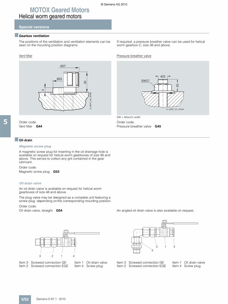
MOTOX Geared MotorsHelical worm geared motors
Special versions
5/52 Siemens D 87.1 · 2010
5
■ Gearbox ventilation
The positions of the ventilation and ventilation elements can be seen on the mounting position diagrams.
If required, a pressure breather valve can be used for helical worm gearbox C, size 38 and above.
Vent filter
Order code:Vent filter G44
Pressure breather valve
SW = Wrench width
Order code:Pressure breather valve G45
■ Oil drain
Magnetic screw plug
A magnetic screw plug for inserting in the oil drainage hole is available on request for helical worm gearboxes of size 48 and above. This serves to collect any grit contained in the gear lubricant.
Order code:Magnetic screw plug G53
Oil drain valve
An oil drain valve is available on request for helical worm gearboxes of size 48 and above.
The plug valve may be designed as a complete unit featuring a screw plug, depending on the corresponding mounting position.
Order code: Oil drain valve, straight G54
Item 3 Screwed connection GE Item 1 Oil drain valveItem 2 Screwed connection EGE Item 4 Screw plug
An angled oil drain valve is also available on request..
Item 3 Screwed connection GE Item 1 Oil drain valveItem 2 Screwed connection EGE Item 4 Screw plug
� � �
� � �
��
�
���������� �
15
ø11
G_D087_XX_00104
SW17
3 2 1 4
32 1 4
© Siemens AG 2010© Siemens AG 2010

MOTOX Geared MotorsHelical worm geared motors
Special versions
5/53Siemens D 87.1 · 2010
5
■ Sealing
Combination shaft sealing
Combination shaft sealing, which helps to prevent oil from leak-ing, is available for helical worm gearboxes of sizes 38 to 88.
Combination shaft sealing is particularly well suited to external use.
Order code:Combination shaft sealing G24
1 • Housing
2 • Rubberized inner and outer diameter
3 • Grease filling prevents dry running of the sealing lips
4 • Additional sealing lips to protect against dirt• Decoupled sealing system prevents scoring of the shaft as
a result of corrosion or dirt
5 • Protected running surface for radial shaft sealing ring• No damage when mounting
6 • Shaft
Double sealing
Double sealing is possible for helical worm gearboxes of size 28. Double sealing is particularly well suited to external use.
Order code:Double sealing MSS1 (size 28) G23Double radial shaft seal (size 188) G22+G31
High temperature resistant sealing
High temperature resistant sealing (Viton/fluorinated rubber) for higher operating temperatures of +60 °C and above are avail-able for helical worm gearboxes.
Order code:High temperature resistant sealing G25
■ Hollow shaft cover (protection cover)
Gearboxes with hollow shafts can be fitted with a fixed protec-tion cover made of cast iron or steel. Gearboxes of size 28 are fitted with a steel protection cover as standard.
The steel protection cover can only be used for gearboxes with hollow shaft and shrink disk.
For outdoor applications we recommend the ATEX versions.
Order codes:Protection cover G62Protection cover (ATEX) G63Steel protection cover G60Steel protection cover (ATEX) G61
CAF, CAZ, CAD, CAFS1), CAZS1), CADS1), CAFT, CAZT, CADT
1) Only a steel protection cover is available for CAFS, CAZS, and CADS
G_D
087_
XX
_000
87
1
2
3
3
5
4
6
Protection
Steel
Protectioncover
cover
Gearbox type
Steel protection cover Protection cover
g7 g8 h8 g6 h6 h7
C.28 58.0 102 36.0 – – –
C.38 82.2 115 40.0 120 10 33
C.48 99.0 130 44.0 132 10 33
C.68 115.0 150 62.5 150 10 37
C.88 137.0 190 70.0 190 13 50
© Siemens AG 2010© Siemens AG 2010

MOTOX Geared MotorsHelical worm geared motors
Special versions
5/54 Siemens D 87.1 · 2010
5
■ Radially reinforced output shaft bearings
The bearings of the MOTOX gearboxes are dimensioned such that they are strong enough to withstand most application cases.
However, the gearboxes can be fitted with a reinforced output shaft bearing arrangement for applications with particularly high radial and axial forces.
Order code:Radially reinforced output shaft bearings G20
■ 2nd output shaft extension
If required, helical worms in a foot-mounted design with solid shaft are available with a 2nd shaft extension.
See the dimension drawings for the corresponding design for the relevant dimensions.
Order code:2nd output shaft extension G73
© Siemens AG 2010© Siemens AG 2010

MOTOX Geared MotorsHelical worm geared motors
Dimensions
5/55Siemens D 87.1 · 2010
5
■ Dimension drawing overview
Representation Gearbox type Dimension drawing on page
C28 / CZ28 5/58
C38 5/66
C48 5/76
C68 5/86
C88 5/96
CF28 5/59
CF38 5/67
CF48 5/77
CF68 5/87
CF88 5/97
CA28 / CAZ28 5/60
CA38 5/68
CA48 5/78
CA68 5/88
CA88 5/98
CAD28 5/61
CAD38 5/69
CAD48 5/79
CAD68 5/89
CAD88 5/99
CAF28 5/62
CAF38 5/70
CAF48 5/80
CAF68 5/90
CAF88 5/100
© Siemens AG 2010© Siemens AG 2010

MOTOX Geared MotorsHelical worm geared motors
Dimensions
5/56 Siemens D 87.1 · 2010
5
■ Dimension drawing overview (continued)
Representation Gearbox type Dimension drawing on page
CAZ38 5/71
CAZ48 5/81
CAZ68 5/91
CAZ88 5/101
CAS28 / CAZS28 5/63
CAS38 5/72
CAS48 5/82
CAS68 5/92
CAS88 5/102
CADS28 5/64
CADS38 5/73
CADS48 5/83
CADS68 5/93
CADS88 5/103
CAFS28 5/65
CAFS38 5/74
CAFS48 5/84
CAFS68 5/94
CAFS88 5/104
CAZS38 5/75
CAZS48 5/85
CAZS68 5/95
CAZS88 5/105
© Siemens AG 2010© Siemens AG 2010

MOTOX Geared MotorsHelical worm geared motors
Dimensions
5/57Siemens D 87.1 · 2010
5
■ Dimension drawing overview (continued)
Representation Gearbox type Dimension drawing on page
CA.S38 ... CA.S88 5/106
CA.T38 ... CA.T88 5/107
C.38-Z28 ... C.88-D/Z38 5/108
Additional flange-mounted design 5/109
© Siemens AG 2010© Siemens AG 2010

MOTOX Geared MotorsHelical worm geared motors
Dimensions
5/58 Siemens D 87.1 · 2010
5
■ Gearbox C/CZ28, foot- and housing-flange-mounted designs (C-type)
C012CZ012
C.28 Weight
Motor k kB AC AD AG LL HH O C.28
LA71 353 408 139 146 90 90 40.5 M20x1.5/M25x1.5 10
LA71Z 372 427 139 146 90 90 40.5 M20x1.5/M25x1.5 11
Z
Z
X
X
Y
Y5
O
4DR M6x16
AG
LLHH
8
55
55 55
Ø86
Ø86
100100
404032 4
Ø20
k6
Ø20
k6
22,5
6AD
963 3
Ø74
j7Ø1
02
Ø74 j
7
9
Ø102
4590
105
AC
8
7035
925 25
2525
9,5
105,5k
kB
63 -0,5M8x16
M8x16
3570
63-0
,570
,5
➃ DIN 332 ➄ Feather key / keyway DIN 6885
© Siemens AG 2010© Siemens AG 2010

MOTOX Geared MotorsHelical worm geared motors
Dimensions
5/59Siemens D 87.1 · 2010
5
■ Gearbox CF28, flange-mounted design (A-type)
CF012
Flange a1 b1 to2 c1 f1
A120 120 80 j6 8 3.0
A160 160 110 j6 9 3.5
Y
Y
Z
Z
X
Xa1=160
5
O
4DR M6x16
AG
LLHH
8
Øa1
136
Ø86
Øa1
Ø100
Øb1 t
o2
40120
c1
136
Ø130
Ø6,6
Ø9
40
32 4
Ø20
k6
f1
22,5
6
AD
963 55
Ø74
j79
Ø102
4590
105AC
8
7035
925 25
2525
9,5
105,5k
kB
63 -0,5
3570
63-0
,570
,5
45°
45°M8x16
CF28 Weight
Motor k kB AC AD AG LL HH O CF28
LA71 353 408 139 146 90 90 40.5 M20x1.5/M25x1.5 12
LA71Z 372 427 139 146 90 90 40.5 M20x1.5/M25x1.5 12
➃ DIN 332 ➄ Feather key / keyway DIN 6885
© Siemens AG 2010© Siemens AG 2010

MOTOX Geared MotorsHelical worm geared motors
Dimensions
5/60 Siemens D 87.1 · 2010
5
■ Gearbox CA/CAZ28, housing-flange-mounted design (C-type)
CA012CAZ012
d l9 l8 M t u
20 *) 23.4 106 M6 22.8 6
25 27.6 105 M10 28.3 8
*) Preferred series
5
4
O
1M
Rmax1
Y
Y
Z
Z
AG
LLHH
8
5555
Ø86
M8x16
Ø86
Ødh6
ØdH7
Ø40
uJS
9AD
963 3
Ø74
j7Ø1
02
Ø74 j
79
Ø102
95
l9
120l8
604040
62
4590
105
AC
8
7035
925 25
2525
9,5
105,5k
kB
63 -0,5M8x16
3570
63-0
,570
,5
t
CA.28 Weight
Motor k kB AC AD AG LL HH O CA.28
LA71 353 408 139 146 90 90 40.5 M20x1.5/M25x1.5 9
LA71Z 372 427 139 146 90 90 40.5 M20x1.5/M25x1.5 10
➃ DIN 332 ➄ Feather key / keyway DIN 6885 ➀ EN ISO 4014
© Siemens AG 2010© Siemens AG 2010

MOTOX Geared MotorsHelical worm geared motors
Dimensions
5/61Siemens D 87.1 · 2010
5
■ Gearbox CAD28, shaft-mounted design with torque arm
CAD012
d l9 l8 M t u
20 *) 23.4 106 M6 22.8 6
25 27.6 105 M10 28.3 8
*) Preferred series
Y
Y
Z
Z
2
3
1
6
4
5
Rmax1
5
4
O1M
AG
LLHH
5x45°
55 6166,5
Ø86
9045
105
1364
Ø25
110
45°8
Ødh6
ØdH7
Ø40
uJS
9
AD
963
Ø11
Ø74
j79
Ø102
95
l9
120l8
604040
62
AC
8
2525
9,5
105,5k
kB
63 -0,5
3570
70,5
t
M8x16
CAD28 Weight
Motor k kB AC AD AG LL HH O CAD28
LA71 353 408 139 146 90 90 40.5 M20x1.5/M25x1.5 10
LA71Z 372 427 139 146 90 90 40.5 M20x1.5/M25x1.5 11
➃ DIN 332 ➄ Feather key / keyway DIN 6885 ➀ EN ISO 4014
© Siemens AG 2010© Siemens AG 2010

MOTOX Geared MotorsHelical worm geared motors
Dimensions
5/62 Siemens D 87.1 · 2010
5
■ Gearbox CAF28, shaft-mounted design with flange
CAF012
Y
Y
Z
Za1=160
Rmax1
5
4
O
1M
AG
LLHH
Øa1
136
136
Ø130
Ø945°
8
Ø86
Øb1
to2
Øa1
Ødh6
ØdH7
Ø40
uJS
9
AD
96
55 803
Ø74
j79
Ø102
95
l9
120l8
604040
62
4590
105AC
8
7035
925 25
2525
9,5
105,5k
kB
63 -0,5
3570
63-0
,570
,5
t
Ø100
c1
Ø6,6 f145°
M8x16
Flange a1 b1 to2 c1 f1 d M l9 l8 t u
A120 120 80 j6 8 3.0 20 *) M6 23.4 106 22.8 6
25 M10 27.6 105 28.3 8
A160 160 110 j6 9 3.5 20 *) M6 23.4 106 22.8 6
25 M10 27.6 105 28.3 8
*) Preferred series
CAF28 Weight
Motor k kB AC AD AG LL HH O CAF28
LA71 353 408 139 146 90 90 40.5 M20x1.5/M25x1.5 11
LA71Z 372 427 139 146 90 90 40.5 M20x1.5/M25x1.5 12
➃ DIN 332 ➄ Feather key / keyway DIN 6885 ➀ EN ISO 4014
© Siemens AG 2010© Siemens AG 2010

MOTOX Geared MotorsHelical worm geared motors
Dimensions
5/63Siemens D 87.1 · 2010
5
■ Gearbox CAS/CAZS28, shaft-mounted design with housing flange (C-type) and shrink disk
CAS012CAZS012
CA.S28 Weight
Motor k kB AC AD AG LL HH O CA.S28
LA71 353 408 139 146 90 90 40.5 M20x1.5/M25x1.5 9
LA71Z 372 427 139 146 90 90 40.5 M20x1.5/M25x1.5 10
Z
Z
Rmax1
O
AG
LLHH
8
5555
Ø86 Ø58
Ø20
h6
25 25142
9
609120
Ø20
H7
Ø20
H7Ø2
0h6
23
AD
963
Ø102
4590
105
AC
8
7035
925 25
2525
9,5
105,5k
kB
63 -0,5M8x16
3570
63-0
,570
,5
Ø74
j7
© Siemens AG 2010© Siemens AG 2010

MOTOX Geared MotorsHelical worm geared motors
Dimensions
5/64 Siemens D 87.1 · 2010
5
■ Gearbox CADS28, shaft-mounted design with torque arm and shrink disk
CADS012
CADS28 Weight
Motor k kB AC AD AG LL HH O CADS28
LA71 353 408 139 146 90 90 40.5 M20x1.5/M25x1.5 10
LA71Z 372 427 139 146 90 90 40.5 M20x1.5/M25x1.5 11
Z
Z
2
3
1
6
4
5
Rmax1
O
AG
LLHH
5x45°
61
9
Ø58
Ø20
h625 25
142
609120
Ø20
H7
Ø20
H7Ø2
0h6
110
9045
105
13
45°
AD
96
Ø11
AC
8
2525
9,5
105,5k
kB
63 -0,58
3570
70,5
64
Ø25
5566,5
23
© Siemens AG 2010© Siemens AG 2010

MOTOX Geared MotorsHelical worm geared motors
Dimensions
5/65Siemens D 87.1 · 2010
5
■ Gearbox CAFS28, shaft-mounted design with flange and shrink disk
CAFS012
Flange a1 b1 to2 c1 f1
A120 120 80 j6 8 3.0
A160 160 110 j6 9 3.5
CAFS28 Weight
Motor k kB AC AD AG LL HH O CAFS28
LA71 353 408 139 146 90 90 40.5 M20x1.5/M25x1.5 11
LA71Z 372 427 139 146 90 90 40.5 M20x1.5/M25x1.5 12
Z
Za1=160
Rmax1
O
AG
LLHH
Øa1
136
136
Ø130
Ø945°
8
Ø58
6091
96
55
4590
105
Ø20
h6
25 25142
20
Ø20
H7
Ø20
H7Ø2
0h6
Øb1
to2
Øa1
AD
80
AC
8
7035
925 25
2525
9,5
105,5k
kB
63 -0,5
3570
63-0
,570
,5
Ø100
c1
Ø6,6 f145°
23
© Siemens AG 2010© Siemens AG 2010

MOTOX Geared MotorsHelical worm geared motors
Dimensions
5/66 Siemens D 87.1 · 2010
5
■ Gearbox C38, foot- and housing-flange-mounted designs (C-type)
C012
d to1 l l3 l4 t u i q DR
25 *) k6 50 40 5 28 8 60 110 M10x22
35 k6 70 56 5 38 10 80 130 M12x28
*) Preferred series
C38 Weight
Motor k kB AC AD AG LL HH O C38
LA71 442.0 497.0 139.0 146 90 90 114.5 M20x1.5/M25x1.5 21
LA71Z 461.0 516.0 139.0 146 90 90 114.5 M20x1.5/M25x1.5 21
LA80 479.0 542.5 156.5 155 90 90 114.0 M20x1.5/M25x1.5 26
LA90S 510.0 581.0 174.0 163 90 90 114.0 M20x1.5/M25x1.5 31
LA90L 510.0 581.0 174.0 163 90 90 114.0 M20x1.5/M25x1.5 31
LA100L 556.0 637.0 195.0 168 120 120 154.5 2xM32x1.5 40
LA112M 585.5 666.5 219.0 181 120 120 160.0 2xM32x1.5 50
X
X
Z
Z
4DR
AB
5
HH
AG
LL
Ødto
1
Ødto
1
35
15
9,5
l3 l4
7615
4
80
O
125AD
Ø11
l 57 57 lq q
Ø11100 i120
3545
100 -
0,575
-0,5
36 40
1575 -0,5 108,5
kkB
ØAC
4036
3636
u
t
➃ DIN 332 ➄ Feather key / keyway DIN 6885
© Siemens AG 2010© Siemens AG 2010

MOTOX Geared MotorsHelical worm geared motors
Dimensions
5/67Siemens D 87.1 · 2010
5
■ Gearbox CF38, flange-mounted design (A-type)
CF012
A
4DR M10x22
5
X
X
Z
Z
HH
AG
LL
35 38,5M10x17
50
60100
10
O
76
AD125
40 5
Ø25 k
6Ø1
10j6
Ø160
57
10 3,550
134
4
11737
63,5
30
7410
0-0
,5 ØAC
45°75 108,5
Ø9
kkB
9,5
8
28
Ø130
CF38 Weight
Motor k kB AC AD AG LL HH O CF38
LA71 442.0 497.0 139.0 146 90 90 114.5 M20x1.5/M25x1.5 25
LA71Z 461.0 516.0 139.0 146 90 90 114.5 M20x1.5/M25x1.5 25
LA80 479.0 542.5 156.5 155 90 90 114.0 M20x1.5/M25x1.5 30
LA90S 510.0 581.0 174.0 163 90 90 114.0 M20x1.5/M25x1.5 34
LA90L 510.0 581.0 174.0 163 90 90 114.0 M20x1.5/M25x1.5 34
LA100L 556.0 637.0 195.0 168 120 120 154.5 2xM32x1.5 44
LA112M 585.5 666.5 219.0 181 120 120 160.0 2xM32x1.5 54
➃ DIN 332 ➄ Feather key / keyway DIN 6885
© Siemens AG 2010© Siemens AG 2010

MOTOX Geared MotorsHelical worm geared motors
Dimensions
5/68 Siemens D 87.1 · 2010
5
■ Gearbox CA38, shaft-mounted design
CA012
d l9 l8 l11 M t u
25 *) 17 105 100 M10 28.3 8
30 31 102 90 M10 33.3 8
*) Preferred series
Z
Z
4
max2.5R
5
1
M
AB
AG
LL
Ødh6
t
ØdH7u
JS9
Ø45
l9
44 44
l8120
l11
63 60
35
15
9,576
15
4
80
O
125AD
Ø11
57 57
Ø11100120
3545
100 -
0,575
-0,5
36 40
1575 -0,5 108,5
kkB
ØAC
4036
3636
HH
CA38 Weight
Motor k kB AC AD AG LL HH O CA38
LA71 442.0 497.0 139.0 146 90 90 114.5 M20x1.5/M25x1.5 20
LA71Z 461.0 516.0 139.0 146 90 90 114.5 M20x1.5/M25x1.5 20
LA80 479.0 542.5 156.5 155 90 90 114.0 M20x1.5/M25x1.5 25
LA90S 510.0 581.0 174.0 163 90 90 114.0 M20x1.5/M25x1.5 30
LA90L 510.0 581.0 174.0 163 90 90 114.0 M20x1.5/M25x1.5 30
LA100L 556.0 637.0 195.0 168 120 120 154.5 2xM32x1.5 39
LA112M 585.5 666.5 219.0 181 120 120 160.0 2xM32x1.5 49
➃ DIN 332 ➄ Feather key / keyway DIN 6885 ➀ EN ISO 4014
© Siemens AG 2010© Siemens AG 2010

MOTOX Geared MotorsHelical worm geared motors
Dimensions
5/69Siemens D 87.1 · 2010
5
■ Gearbox CAD38, shaft-mounted design with torque arm
CAD012
d l9 l8 l11 M t u
25 *) 17 105 100 M10 28.3 8
30 31 102 90 M10 33.3 8
*) Preferred series
2
4
6
8
1
79
Fig.1
2
46
8
Fig.2
1
3
5
7
9
max2.5R
5
1
M
4
ABY
Y
Z
Z
HH
M8x1460°
Ø100AG
LL
5x30° (=150°) 8x30° (=240°)
15°
78
54
Ødh6
ØdH7
Ø45
6469
130
32Ø16 H938
360°
Ø80 j
6
100
t
uJS
9
Ø45
l9
44 44
l8120
l11
63 60
10
O
76
AD125
Ø120
4
74
ØAC
75 108,5k
9,5
kB
CAD38 Weight
Motor k kB AC AD AG LL HH O CAD38
LA71 442.0 497.0 139.0 146 90 90 114.5 M20x1.5/M25x1.5 23
LA71Z 461.0 516.0 139.0 146 90 90 114.5 M20x1.5/M25x1.5 23
LA80 479.0 542.5 156.5 155 90 90 114.0 M20x1.5/M25x1.5 28
LA90S 510.0 581.0 174.0 163 90 90 114.0 M20x1.5/M25x1.5 32
LA90L 510.0 581.0 174.0 163 90 90 114.0 M20x1.5/M25x1.5 32
LA100L 556.0 637.0 195.0 168 120 120 154.5 2xM32x1.5 41
LA112M 585.5 666.5 219.0 181 120 120 160.0 2xM32x1.5 52
➃ DIN 332 ➄ Feather key / keyway DIN 6885 ➀ EN ISO 4014
© Siemens AG 2010© Siemens AG 2010

MOTOX Geared MotorsHelical worm geared motors
Dimensions
5/70 Siemens D 87.1 · 2010
5
■ Gearbox CAF38, shaft-mounted design with flange
CAF012
Z
Z
max2.5R
5
1
M
4
AB
6HH
AG
LL
Ødh6
60
57 84
t
ØdH7
uJS
9
Ø45
l9
44 44
l8120
l11
63 60
100
10
O
76
AD125
Ø110
j6Ø1
60
10 3,5
M10x174
11737
63,5
3035 38,5
7410
0 -0,5
ØAC
45°75 108,5
Ø9
kkB
9,5
Ø130
d l9 l8 l11 M t u
25 *) 17 105 100 M10 28.3 8
30 31 102 90 M10 33.3 8
*) Preferred series
CAF38 Weight
Motor k kB AC AD AG LL HH O CAF38
LA71 442.0 497.0 139.0 146 90 90 114.5 M20x1.5/M25x1.5 24
LA71Z 461.0 516.0 139.0 146 90 90 114.5 M20x1.5/M25x1.5 24
LA80 479.0 542.5 156.5 155 90 90 114.0 M20x1.5/M25x1.5 29
LA90S 510.0 581.0 174.0 163 90 90 114.0 M20x1.5/M25x1.5 33
LA90L 510.0 581.0 174.0 163 90 90 114.0 M20x1.5/M25x1.5 33
LA100L 556.0 637.0 195.0 168 120 120 154.5 2xM32x1.5 42
LA112M 585.5 666.5 219.0 181 120 120 160.0 2xM32x1.5 53
➃ DIN 332 ➄ Feather key / keyway DIN 6885 ➀ EN ISO 4014 ➅ For note, see page 5/109
© Siemens AG 2010© Siemens AG 2010

MOTOX Geared MotorsHelical worm geared motors
Dimensions
5/71Siemens D 87.1 · 2010
5
■ Gearbox CAZ38, shaft-mounted design with housing flange (C-type)
CAZ012
d l9 l8 l11 M t u
25 *) 17 105 100 M10 28.3 8
30 31 102 90 M10 33.3 8
*) Preferred series
CAZ38 Weight
Motor k kB AC AD AG LL HH O CAZ38
LA71 442.0 497.0 139.0 146 90 90 114.5 M20x1.5/M25x1.5 22
LA71Z 461.0 516.0 139.0 146 90 90 114.5 M20x1.5/M25x1.5 22
LA80 479.0 542.5 156.5 155 90 90 114.0 M20x1.5/M25x1.5 27
LA90S 510.0 581.0 174.0 163 90 90 114.0 M20x1.5/M25x1.5 32
LA90L 510.0 581.0 174.0 163 90 90 114.0 M20x1.5/M25x1.5 32
LA100L 556.0 637.0 195.0 168 120 120 154.5 2xM32x1.5 41
LA112M 585.5 666.5 219.0 181 120 120 160.0 2xM32x1.5 51
Z
Z
max2.5R
5
1
M
4
AB
HH
AG
LL
35 38,5M10x17
54 54
Ø100
63,5
37 30
60
117
3360°
Ø80
j6
Ø80
j6
100
t
ØdH7
uJS
9
Ø45
Ødh6
l9
44 44
l8120
l11
63 60
10
O
76
AD125
Ø120
Ø120
4
7410
0-0
,5 ØAC
75 108,5M8x14
k
9,5
kB
© Siemens AG 2010© Siemens AG 2010

MOTOX Geared MotorsHelical worm geared motors
Dimensions
5/72 Siemens D 87.1 · 2010
5
■ Gearbox CAS38, shaft-mounted design with shrink disk
CAS012
CAS38 Weight
Motor k kB AC AD AG LL HH O CAS38
LA71 442.0 497.0 139.0 146 90 90 114.5 M20x1.5/M25x1.5 21
LA71Z 461.0 516.0 139.0 146 90 90 114.5 M20x1.5/M25x1.5 21
LA80 479.0 542.5 156.5 155 90 90 114.0 M20x1.5/M25x1.5 25
LA90S 510.0 581.0 174.0 163 90 90 114.0 M20x1.5/M25x1.5 30
LA90L 510.0 581.0 174.0 163 90 90 114.0 M20x1.5/M25x1.5 30
LA100L 556.0 637.0 195.0 168 120 120 154.5 2xM32x1.5 39
LA112M 585.5 666.5 219.0 181 120 120 160.0 2xM32x1.5 50
Z
Z
maxR 1.0
AB
HH
AG
LL
Ø77
Ø30
h6Ø3
0H7
Ø30
H7
2294 60
20
14627 25
Ø30
h6
35
15
9,5
7615
4
80
O
125AD
Ø11
57 57
Ø11100120
3545
100 -
0,575
-0,5
36 40
1575 -0,5 108,5
kkB
ØAC
4036
3636
© Siemens AG 2010© Siemens AG 2010

MOTOX Geared MotorsHelical worm geared motors
Dimensions
5/73Siemens D 87.1 · 2010
5
■ Gearbox CADS38, shaft-mounted design with torque arm and shrink disk
CADS012
CADS38 Weight
Motor k kB AC AD AG LL HH O CADS38
LA71 442.0 497.0 139.0 146 90 90 114.5 M20x1.5/M25x1.5 23
LA71Z 461.0 516.0 139.0 146 90 90 114.5 M20x1.5/M25x1.5 23
LA80 479.0 542.5 156.5 155 90 90 114.0 M20x1.5/M25x1.5 28
LA90S 510.0 581.0 174.0 163 90 90 114.0 M20x1.5/M25x1.5 33
LA90L 510.0 581.0 174.0 163 90 90 114.0 M20x1.5/M25x1.5 33
LA100L 556.0 637.0 195.0 168 120 120 154.5 2xM32x1.5 42
LA112M 585.5 666.5 219.0 181 120 120 160.0 2xM32x1.5 52
2
4
6
8
1
79
Fig.1
2
46
8
Fig.2
1
3
5
7
9
maxR 1.0
ABY
Y
Z
Z
HH
M8x1460°
Ø100AG
LL
5x30° (=150°) 8x30° (=240°)
15°
7869
54
Ø77
Ø30
h6Ø3
0H7
Ø30
H7
2294 60
20
14627 25
Ø30
h6
Ø45
64
130
32Ø16 H938
360°
Ø80
j6
100
10
O
76
AD125
Ø120
4
74
ØAC
75 108,5k
9,5
kB
© Siemens AG 2010© Siemens AG 2010

MOTOX Geared MotorsHelical worm geared motors
Dimensions
5/74 Siemens D 87.1 · 2010
5
■ Gearbox CAFS38, shaft-mounted design with flange and shrink disk
CAFS012
CAFS38 Weight
Motor k kB AC AD AG LL HH O CAFS38
LA71 442.0 497.0 139.0 146 90 90 114.5 M20x1.5/M25x1.5 24
LA71Z 461.0 516.0 139.0 146 90 90 114.5 M20x1.5/M25x1.5 24
LA80 479.0 542.5 156.5 155 90 90 114.0 M20x1.5/M25x1.5 29
LA90S 510.0 581.0 174.0 163 90 90 114.0 M20x1.5/M25x1.5 34
LA90L 510.0 581.0 174.0 163 90 90 114.0 M20x1.5/M25x1.5 34
LA100L 556.0 637.0 195.0 168 120 120 154.5 2xM32x1.5 43
LA112M 585.5 666.5 219.0 181 120 120 160.0 2xM32x1.5 53
Z
Z
maxR 1.0
AB
6
HH
AG
LL
35 38,5M10x17
Ø77
60
Ø30
h6Ø3
0H7
Ø30
H7
2294 60
20
14627 25
Ø30
h6
57 84
100
10
O
76
AD125
Ø110
j6Ø1
60
10 3,5
4
11737
63,5
30
7410
0 -0,5
ØAC
45°75 108,5
Ø9
kkB
9,5Ø130
➅ For note, see page 5/109
© Siemens AG 2010© Siemens AG 2010

MOTOX Geared MotorsHelical worm geared motors
Dimensions
5/75Siemens D 87.1 · 2010
5
■ Gearbox CAZS38, shaft-mounted design with housing flange (C-type) and shrink disk
CAZS012
CAZS38 Weight
Motor k kB AC AD AG LL HH O CAZS38
LA71 442.0 497.0 139.0 146 90 90 114.5 M20x1.5/M25x1.5 23
LA71Z 461.0 516.0 139.0 146 90 90 114.5 M20x1.5/M25x1.5 23
LA80 479.0 542.5 156.5 155 90 90 114.0 M20x1.5/M25x1.5 27
LA90S 510.0 581.0 174.0 163 90 90 114.0 M20x1.5/M25x1.5 32
LA90L 510.0 581.0 174.0 163 90 90 114.0 M20x1.5/M25x1.5 32
LA100L 556.0 637.0 195.0 168 120 120 154.5 2xM32x1.5 41
LA112M 585.5 666.5 219.0 181 120 120 160.0 2xM32x1.5 52
Z
Z
maxR 1.0
AB
AG
LLHH
35 38,5M10x17
54 54
Ø77
Ø30
H7Ø3
0h6
Ø30
H7
2294 60
20
14627 25
Ø30
h6
Ø100
63,5
37 30
60
117
3360°
Ø80
j6
Ø80
j6
100
10
O
76
AD125
Ø120
Ø120
4
7410
0-0
,5 ØAC
75 108,5M8x14
k
9,5
kB
© Siemens AG 2010© Siemens AG 2010

MOTOX Geared MotorsHelical worm geared motors
Dimensions
5/76 Siemens D 87.1 · 2010
5
■ Gearbox C48, foot- and housing-flange-mounted designs (C-type)
C012
d to1 l l3 l4 t u i q DR
30 *) k6 60 50 3.5 33 8 80 135 M10x22
40 k6 80 70 5.0 43 12 100 155 M16x36
*) Preferred series
C48 Weight
Motor k kB AC AD AG LL HH O C48
LA71 459.5 514.5 139.0 146 90 90 114.5 M20x1.5/M25x1.5 30
LA71Z 478.5 533.5 139.0 146 90 90 114.5 M20x1.5/M25x1.5 30
LA80 496.5 560.0 156.5 155 90 90 114.0 M20x1.5/M25x1.5 34
LA90S 527.5 598.5 174.0 163 90 90 114.0 M20x1.5/M25x1.5 39
LA90L 527.5 598.5 174.0 163 90 90 114.0 M20x1.5/M25x1.5 39
LA100L 573.5 654.5 195.0 168 120 120 154.5 2xM32x1.5 48
LA112M 603.0 684.0 219.0 181 120 120 160.0 2xM32x1.5 59
X
X
Z
Z
4DR
AB
5
HH
AG
LL
Ødto
1
Ødto
1
45
15
21,5
l3 l4
7615
4
100
O
125AD
Ø11
l 71 71 lq q
Ø11110 i136
4555
112 -
0,580
-0,5
40 45
1580 -0,5 121
kkB
ØAC
4540
4040
u
t
➃ DIN 332 ➄ Feather key / keyway DIN 6885
© Siemens AG 2010© Siemens AG 2010

MOTOX Geared MotorsHelical worm geared motors
Dimensions
5/77Siemens D 87.1 · 2010
5
■ Gearbox CF48, flange-mounted design (A-type)
CF012
A
4DR M10x22
5
X
X
Z
Z
HH
AG
LL
40,5 40,5M10x17
60
73110
12
O
76
AD125
50 3,5
Ø30 k
6Ø1
30j6
Ø200
71
12 3,560
160
4
11736,5
58,5
33
7911
2-0
,5 ØAC
45°80 121
Ø11
kkB
21,5
8
33
Ø165
CF48 Weight
Motor k kB AC AD AG LL HH O CF48
LA71 459.5 514.5 139.0 146 90 90 114.5 M20x1.5/M25x1.5 34
LA71Z 478.5 533.5 139.0 146 90 90 114.5 M20x1.5/M25x1.5 34
LA80 496.5 560.0 156.5 155 90 90 114.0 M20x1.5/M25x1.5 39
LA90S 527.5 598.5 174.0 163 90 90 114.0 M20x1.5/M25x1.5 43
LA90L 527.5 598.5 174.0 163 90 90 114.0 M20x1.5/M25x1.5 43
LA100L 573.5 654.5 195.0 168 120 120 154.5 2xM32x1.5 52
LA112M 603.0 684.0 219.0 181 120 120 160.0 2xM32x1.5 63
➃ DIN 332 ➄ Feather key / keyway DIN 6885
© Siemens AG 2010© Siemens AG 2010

MOTOX Geared MotorsHelical worm geared motors
Dimensions
5/78 Siemens D 87.1 · 2010
5
■ Gearbox CA48, shaft-mounted design
CA012
d l9 l8 l11 M t u
30 *) 17 132 127 M10 33.3 8
35 40 128 115 M12 38.3 10
40 48 128 115 M16 43.3 12
*) Preferred series
Z
Z
4
max2.5R
5
1
M
AB
HH
AG
LL
Ødh6
t
uJS
9
ØdH7 Ø5
5
l9
58 58
l8150
l11
78 75
45
15
21,5
76
15
4
100
O
125AD
Ø11
71 71
Ø11110136
4555
112 -
0,580
-0,5
40 45
1580 -0,5 121
kkB
ØAC
4540
4040
CA48 Weight
Motor k kB AC AD AG LL HH O CA48
LA71 459.5 514.5 139.0 146 90 90 114.5 M20x1.5/M25x1.5 28
LA71Z 478.5 533.5 139.0 146 90 90 114.5 M20x1.5/M25x1.5 28
LA80 496.5 560.0 156.5 155 90 90 114.0 M20x1.5/M25x1.5 33
LA90S 527.5 598.5 174.0 163 90 90 114.0 M20x1.5/M25x1.5 38
LA90L 527.5 598.5 174.0 163 90 90 114.0 M20x1.5/M25x1.5 38
LA100L 573.5 654.5 195.0 168 120 120 154.5 2xM32x1.5 47
LA112M 603.0 684.0 219.0 181 120 120 160.0 2xM32x1.5 57
➃ DIN 332 ➄ Feather key / keyway DIN 6885 ➀ EN ISO 4014
© Siemens AG 2010© Siemens AG 2010

MOTOX Geared MotorsHelical worm geared motors
Dimensions
5/79Siemens D 87.1 · 2010
5
■ Gearbox CAD48, shaft-mounted design with torque arm
CAD012
2
4
6
8
1
79
Fig.1
2
46
8
Fig.2
1
3
5
7
9
max2.5R
5
1
M
4
ABY
Y
Z
Z
HH
AG
LL
5x30° (=150°) 8x30° (=240°)
15°
90,5
68
Ødh6
ØdH7
Ø50
8087
160
32Ø16 H938
360°
Ø95 j
6
M10x1760°
Ø115
110
t
uJS
9
Ø55
l9
58 58
l8150
l11
78 75
12
O
112
AD125
Ø132
4
79
ØAC
80 121k
21,5
kB
d l9 l8 l11 M t u
30 *) 17 132 127 M10 33.3 8
35 40 128 115 M12 38.3 10
40 48 128 115 M16 43.3 12
*) Preferred series
CAD48 Weight
Motor k kB AC AD AG LL HH O CAD48
LA71 459.5 514.5 139.0 146 90 90 114.5 M20x1.5/M25x1.5 31
LA71Z 478.5 533.5 139.0 146 90 90 114.5 M20x1.5/M25x1.5 31
LA80 496.5 560.0 156.5 155 90 90 114.0 M20x1.5/M25x1.5 36
LA90S 527.5 598.5 174.0 163 90 90 114.0 M20x1.5/M25x1.5 40
LA90L 527.5 598.5 174.0 163 90 90 114.0 M20x1.5/M25x1.5 40
LA100L 573.5 654.5 195.0 168 120 120 154.5 2xM32x1.5 49
LA112M 603.0 684.0 219.0 181 120 120 160.0 2xM32x1.5 60
➃ DIN 332 ➄ Feather key / keyway DIN 6885 ➀ EN ISO 4014
© Siemens AG 2010© Siemens AG 2010

MOTOX Geared MotorsHelical worm geared motors
Dimensions
5/80 Siemens D 87.1 · 2010
5
■ Gearbox CAF48, shaft-mounted design with flange
CAF012
Z
Z
max2.5R
5
1
M
4
AB
6HH
AG
LL
Ødh6
73
71 100
t
ØdH7
uJS
9
Ø55
l9
58 58
l8150
l11
78 75
110
12
O
76
AD125
Ø130
j6Ø2
00
12 3,5
M10x174
11736,5
58,5
3340,5 40,5
7911
2 -0,5
ØAC
45°80 121
Ø11
kkB
21,5
Ø165
d l9 l8 l11 M t u
30 *) 17 132 127 M10 33.3 8
35 40 128 115 M12 38.3 10
40 48 128 115 M16 43.3 12
*) Preferred series
CAF48 Weight
Motor k kB AC AD AG LL HH O CAF48
LA71 459.5 514.5 139.0 146 90 90 114.5 M20x1.5/M25x1.5 32
LA71Z 478.5 533.5 139.0 146 90 90 114.5 M20x1.5/M25x1.5 32
LA80 496.5 560.0 156.5 155 90 90 114.0 M20x1.5/M25x1.5 37
LA90S 527.5 598.5 174.0 163 90 90 114.0 M20x1.5/M25x1.5 42
LA90L 527.5 598.5 174.0 163 90 90 114.0 M20x1.5/M25x1.5 42
LA100L 573.5 654.5 195.0 168 120 120 154.5 2xM32x1.5 51
LA112M 603.0 684.0 219.0 181 120 120 160.0 2xM32x1.5 61
➀ EN ISO 4014 ➃ DIN 332 ➄ Feather key / keyway DIN 6885 ➅ For note, see page 5/109
© Siemens AG 2010© Siemens AG 2010

MOTOX Geared MotorsHelical worm geared motors
Dimensions
5/81Siemens D 87.1 · 2010
5
■ Gearbox CAZ48, shaft-mounted design with housing flange (C-type)
CAZ012
d l9 l8 l11 M t u
30 *) 17 132 127 M10 33.3 8
35 40 128 115 M12 38.3 10
40 48 128 115 M16 43.3 12
*) Preferred series
CAZ48 Weight
Motor k kB AC AD AG LL HH O CAZ48
LA71 459.5 514.5 139.0 146 90 90 114.5 M20x1.5/M25x1.5 30
LA71Z 478.5 533.5 139.0 146 90 90 114.5 M20x1.5/M25x1.5 30
LA80 496.5 560.0 156.5 155 90 90 114.0 M20x1.5/M25x1.5 34
LA90S 527.5 598.5 174.0 163 90 90 114.0 M20x1.5/M25x1.5 39
LA90L 527.5 598.5 174.0 163 90 90 114.0 M20x1.5/M25x1.5 39
LA100L 573.5 654.5 195.0 168 120 120 154.5 2xM32x1.5 48
LA112M 603.0 684.0 219.0 181 120 120 160.0 2xM32x1.5 59
Z
Z
max2.5R
5
1
M
4
AB
HH
AG
LL
40,5 40,5M10x17
68 68
Ø115
58,5
36,5 33
73
117
3360°
Ø95
j6
Ø95
j6
110
t
ØdH7
uJS
9
Ø55
Ødh6
l9
58 58
l8150
l11
78 75
12
O
76
AD125
Ø132
Ø132
4
7911
2-0
,5 ØAC
80 121M10x17
k
21,5
kB
➀ EN ISO 4014 ➃ DIN 332 ➄ Feather key / keyway DIN 6885
© Siemens AG 2010© Siemens AG 2010

MOTOX Geared MotorsHelical worm geared motors
Dimensions
5/82 Siemens D 87.1 · 2010
5
■ Gearbox CAS48, shaft-mounted design with shrink disk
CAS012
d d1 l m4 m5 m6 m7 q1 q g7
35 *) 35 177 32 20 37 25 109 75 93
40 40 177 25 20 30 25 109 75 93
*) Preferred series
CAS48 Weight
Motor k kB AC AD AG LL HH O CAS48
LA71 459.5 514.5 139.0 146 90 90 114.5 M20x1.5/M25x1.5 29
LA71Z 478.5 533.5 139.0 146 90 90 114.5 M20x1.5/M25x1.5 29
LA80 496.5 560.0 156.5 155 90 90 114.0 M20x1.5/M25x1.5 34
LA90S 527.5 598.5 174.0 163 90 90 114.0 M20x1.5/M25x1.5 38
LA90L 527.5 598.5 174.0 163 90 90 114.0 M20x1.5/M25x1.5 38
LA100L 573.5 654.5 195.0 168 120 120 154.5 2xM32x1.5 47
LA112M 603.0 684.0 219.0 181 120 120 160.0 2xM32x1.5 58
Z
Z
maxR 1.0
AB
HH
AG
LL
Øg7
Ød1
h6Ød
1H7
ØdH7
m4q1 q
m5
lm6 m7
Ødh6
45
15
21,5
7615
4
100
O
125AD
Ø11
71 71
Ø11110136
4555
112 -
0,580
-0,5
40 45
1580 -0,5 121
kkB
ØAC
4540
4040
© Siemens AG 2010© Siemens AG 2010
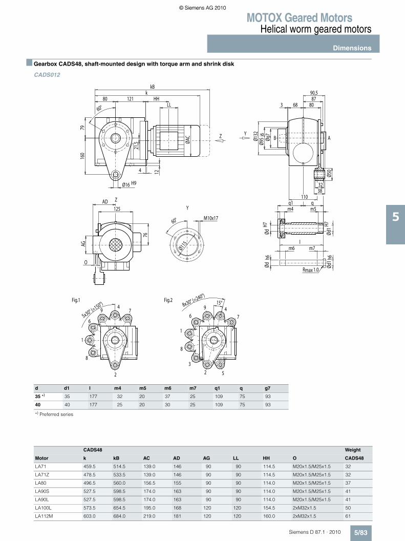
MOTOX Geared MotorsHelical worm geared motors
Dimensions
5/83Siemens D 87.1 · 2010
5
■ Gearbox CADS48, shaft-mounted design with torque arm and shrink disk
CADS012
d d1 l m4 m5 m6 m7 q1 q g7
35 *) 35 177 32 20 37 25 109 75 93
40 40 177 25 20 30 25 109 75 93
*) Preferred series
CADS48 Weight
Motor k kB AC AD AG LL HH O CADS48
LA71 459.5 514.5 139.0 146 90 90 114.5 M20x1.5/M25x1.5 32
LA71Z 478.5 533.5 139.0 146 90 90 114.5 M20x1.5/M25x1.5 32
LA80 496.5 560.0 156.5 155 90 90 114.0 M20x1.5/M25x1.5 37
LA90S 527.5 598.5 174.0 163 90 90 114.0 M20x1.5/M25x1.5 41
LA90L 527.5 598.5 174.0 163 90 90 114.0 M20x1.5/M25x1.5 41
LA100L 573.5 654.5 195.0 168 120 120 154.5 2xM32x1.5 50
LA112M 603.0 684.0 219.0 181 120 120 160.0 2xM32x1.5 61
2
4
6
8
1
79
Fig.1
2
46
8
Fig.2
1
3
5
7
9
maxR 1.0
ABY
Y
Z
Z
HH
M10x1760°
Ø115AG
LL
5x30° (=150°) 8x30° (=240°)
15°
90,587
68
Øg7
Ød1 h
6Ød
1H7
ØdH7
m4q1 q
m5
lm6 m7
Ødh6
Ø50
80
160
32Ø16 H938
360°
Ø95
j6
110
12
O
76
AD125
Ø132
4
79
ØAC
80 121k
21,5
kB
© Siemens AG 2010© Siemens AG 2010
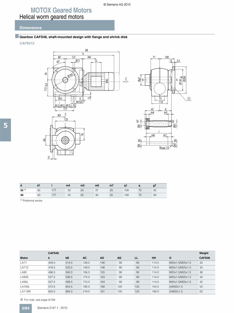
MOTOX Geared MotorsHelical worm geared motors
Dimensions
5/84 Siemens D 87.1 · 2010
5
■ Gearbox CAFS48, shaft-mounted design with flange and shrink disk
CAFS012
Z
Z
maxR 1.0
AB
6
HH
AG
LL
40,5 40,5M10x17
Øg7
73
Ød1
h6Ød
1H7
ØdH7
m4q1 q
m5
lm6 m7
Ødh6
71 100
110
12
O
76
AD125
Ø130
j6Ø2
00
12 3,5
4
11736,5
58,5
33
7911
2 -0,5
ØAC
45°80 121
Ø11
kkB
21,5
Ø165
d d1 l m4 m5 m6 m7 q1 q g7
35 *) 35 177 32 20 37 25 109 75 93
40 40 177 25 20 30 25 109 75 93
*) Preferred series
CAFS48 Weight
Motor k kB AC AD AG LL HH O CAFS48
LA71 459.5 514.5 139.0 146 90 90 114.5 M20x1.5/M25x1.5 33
LA71Z 478.5 533.5 139.0 146 90 90 114.5 M20x1.5/M25x1.5 33
LA80 496.5 560.0 156.5 155 90 90 114.0 M20x1.5/M25x1.5 38
LA90S 527.5 598.5 174.0 163 90 90 114.0 M20x1.5/M25x1.5 42
LA90L 527.5 598.5 174.0 163 90 90 114.0 M20x1.5/M25x1.5 42
LA100L 573.5 654.5 195.0 168 120 120 154.5 2xM32x1.5 52
LA112M 603.0 684.0 219.0 181 120 120 160.0 2xM32x1.5 62
➅ For note, see page 5/109
© Siemens AG 2010© Siemens AG 2010

MOTOX Geared MotorsHelical worm geared motors
Dimensions
5/85Siemens D 87.1 · 2010
5
■ Gearbox CAZS48, shaft-mounted design with housing flange (C-type) and shrink disk
CAZS012
Z
Z
maxR 1.0
AB
HH
AG
LL
40,5 40,5M10x17
68 68
Øg7
Ød1
H7Ød
1h6
ØdH7
m4q1 q
m5
lm6 m7
Ødh6
Ø115
58,5
36,5 33
73
117
3360°
Ø95
j6
Ø95
j6
110
12
O
76
AD125
Ø132
Ø132
4
7911
2-0
,5 ØAC
80 121M10x17
k
21,5
kB
d d1 l m4 m5 m6 m7 q1 q g7
35 *) 35 177 32 20 37 25 109 75 93
40 40 177 25 20 30 25 109 75 93
*) Preferred series
CAZS48 Weight
Motor k kB AC AD AG LL HH O CAZS48
LA71 459.5 514.5 139.0 146 90 90 114.5 M20x1.5/M25x1.5 30
LA71Z 478.5 533.5 139.0 146 90 90 114.5 M20x1.5/M25x1.5 30
LA80 496.5 560.0 156.5 155 90 90 114.0 M20x1.5/M25x1.5 35
LA90S 527.5 598.5 174.0 163 90 90 114.0 M20x1.5/M25x1.5 40
LA90L 527.5 598.5 174.0 163 90 90 114.0 M20x1.5/M25x1.5 40
LA100L 573.5 654.5 195.0 168 120 120 154.5 2xM32x1.5 49
LA112M 603.0 684.0 219.0 181 120 120 160.0 2xM32x1.5 60
© Siemens AG 2010© Siemens AG 2010

MOTOX Geared MotorsHelical worm geared motors
Dimensions
5/86 Siemens D 87.1 · 2010
5
■ Gearbox C68, foot- and housing-flange-mounted designs (C-type)
C012
d to1 l l3 l4 t u i q DR
35 *) k6 70 56 5 38.0 10 95 160 M12x28
40 k6 80 70 5 43.0 12 105 170 M16x36
50 k6 100 80 10 53.5 14 125 190 M16x36
*) Preferred series
C68 Weight
Motor k kB AC AD AG LL HH O C68
LA71 504 559.0 139.0 146 90 90 109.0 M20x1.5/M25x1.5 46
LA71Z 523 578.0 139.0 146 90 90 109.0 M20x1.5/M25x1.5 46
LA80 541 604.5 156.5 155 90 90 108.5 M20x1.5/M25x1.5 51
LA90S 572 643.0 174.0 163 90 90 108.5 M20x1.5/M25x1.5 56
LA90L 572 643.0 174.0 163 90 90 108.5 M20x1.5/M25x1.5 56
LA100L 618 699.0 195.0 168 120 120 149.0 2xM32x1.5 65
LA112M 647 728.0 219.0 181 120 120 154.0 2xM32x1.5 76
LA132S 709 811.0 259.0 195 140 140 196.5 2xM32x1.5 86
LA132M 709 811.0 259.0 195 140 140 196.5 2xM32x1.5 86
LA132ZM 755 857.0 259.0 195 140 140 196.5 2xM32x1.5 95
X
X
Z
Z
4DR
AB
5
HH
AG
LL
150
Ødto
1
Ødto
1
60
18
31
l3 l4
9518
4
130
O
160AD
Ø13,5
l 86 86 lq q
Ø13,5130 i160
6070
140 -
0,510
6-0
,5
51 57
18106 -0,5 145
kkB
ØAC
5751
5051
u
t
➃ DIN 332 ➄ Feather key / keyway DIN 6885
© Siemens AG 2010© Siemens AG 2010

MOTOX Geared MotorsHelical worm geared motors
Dimensions
5/87Siemens D 87.1 · 2010
5
■ Gearbox CF68, flange-mounted design (A-type)
CF012
Flange a1 b1 to2 c1 e1 f1 s1 d to1 l l3 l4 t u i2 q DR
A200 200 130 j6 12 165 4 11.0 35 *) k6 70 56 5 38 10 70 202.5 M12x28
A250 250 180 j6 15 215 4 13.5 40 k6 80 70 5 43 12 80 193.0 M16x36
*) Preferred series
4DR
5
X
X
Z
Z
HH
AG
53 53M12x21
l
88140
148
12
O
95
AD160
l3 l4
Ødto
1Øb
1to2
Øa1
86
c1 f1i2
q
4
15238
76
38
105
140 -
0,5
ØAC
45°
107 145Øs1
kkB
31
u
t
LL
Øe1
CF68 Weight
Motor k kB AC AD AG LL HH O CF68
LA71 505 560.0 139.0 146 90 90 109.0 M20x1.5/M25x1.5 55
LA71Z 524 579.0 139.0 146 90 90 109.0 M20x1.5/M25x1.5 55
LA80 542 605.5 156.5 155 90 90 108.5 M20x1.5/M25x1.5 60
LA90S 573 644.0 174.0 163 90 90 108.5 M20x1.5/M25x1.5 65
LA90L 573 644.0 174.0 163 90 90 108.5 M20x1.5/M25x1.5 65
LA100L 619 700.0 195.0 168 120 120 149.0 2xM32x1.5 74
LA112M 648 729.0 219.0 181 120 120 154.0 2xM32x1.5 85
LA132S 710 812.0 259.0 195 140 140 196.5 2xM32x1.5 95
LA132M 710 812.0 259.0 195 140 140 196.5 2xM32x1.5 95
LA132ZM 756 858.0 259.0 195 140 140 196.5 2xM32x1.5 104
➃ DIN 332 ➄ Feather key / keyway DIN 6885
© Siemens AG 2010© Siemens AG 2010

MOTOX Geared MotorsHelical worm geared motors
Dimensions
5/88 Siemens D 87.1 · 2010
5
■ Gearbox CA68, shaft-mounted design
CA012
d l9 M t u
40 *) 48 M16 43.3 12
45 47 M16 48.3 14
*) Preferred series
Z
Z
4max2.5R
5
1
M
AB
HH
AG
LL
ØdH7
Ødh6
150
t
uJS
9
Ø65
l9
69 69
150180
135
93 90
60
18
3195
18
4
130
O
160AD
Ø13,5
86 86
Ø13,5130160
6070
140 -
0,510
6-0
,5
51 57
18106 -0,5 145
kkB
ØAC
5751
5051
CA68 Weight
Motor k kB AC AD AG LL HH O CA68
LA71 504 559.0 139.0 146 90 90 109.0 M20x1.5/M25x1.5 43
LA71Z 523 578.0 139.0 146 90 90 109.0 M20x1.5/M25x1.5 43
LA80 541 604.5 156.5 155 90 90 108.5 M20x1.5/M25x1.5 48
LA90S 572 643.0 174.0 163 90 90 108.5 M20x1.5/M25x1.5 52
LA90L 572 643.0 174.0 163 90 90 108.5 M20x1.5/M25x1.5 52
LA100L 618 699.0 195.0 168 120 120 149.0 2xM32x1.5 61
LA112M 647 728.0 219.0 181 120 120 154.0 2xM32x1.5 73
LA132S 709 811.0 259.0 195 140 140 196.5 2xM32x1.5 83
LA132M 709 811.0 259.0 195 140 140 196.5 2xM32x1.5 83
LA132ZM 755 857.0 259.0 195 140 140 196.5 2xM32x1.5 92
➃ DIN 332 ➄ Feather key / keyway DIN 6885 ➀ EN ISO 4014
© Siemens AG 2010© Siemens AG 2010

MOTOX Geared MotorsHelical worm geared motors
Dimensions
5/89Siemens D 87.1 · 2010
5
■ Gearbox CAD68, shaft-mounted design with torque arm
CAD012
d l9 M t u
40 *) 48 M16 43.3 12
45 47 M16 48.3 14
*) Preferred series
2
4
6
8
1
3 5
79
Fig.1
2
46
8
Fig.2
1
3
5
7
9
max2.5R
5
1
M
4
ABY
Y
Z
Z
HH
M12x2160°
Ø130AG
LL
8x30° (=240°) 8x30° (=240°)
15°
97,5106106,5
82,5
Ø60
148
200
40Ø25 H946
3,5
60°
Ø110
j6
140
Ødh6
t
uJS
9
ØdH7
Ø65
l9
69 69
150180
135
93 90
12
O
95
AD160
Ø150
4
105
ØAC
107 145k
31
kB
CAD68 Weight
Motor k kB AC AD AG LL HH O CAD68
LA71 505 560.0 139.0 146 90 90 109.0 M20x1.5/M25x1.5 48
LA71Z 524 579.0 139.0 146 90 90 109.0 M20x1.5/M25x1.5 48
LA80 542 605.5 156.5 155 90 90 108.5 M20x1.5/M25x1.5 53
LA90S 573 644.0 174.0 163 90 90 108.5 M20x1.5/M25x1.5 57
LA90L 573 644.0 174.0 163 90 90 108.5 M20x1.5/M25x1.5 57
LA100L 619 700.0 195.0 168 120 120 149.0 2xM32x1.5 67
LA112M 648 729.0 219.0 181 120 120 154.0 2xM32x1.5 78
LA132S 710 812.0 259.0 195 140 140 196.5 2xM32x1.5 88
LA132M 710 812.0 259.0 195 140 140 196.5 2xM32x1.5 88
LA132ZM 756 858.0 259.0 195 140 140 196.5 2xM32x1.5 97
➃ DIN 332 ➄ Feather key / keyway DIN 6885 ➀ EN ISO 4014
© Siemens AG 2010© Siemens AG 2010

MOTOX Geared MotorsHelical worm geared motors
Dimensions
5/90 Siemens D 87.1 · 2010
5
■ Gearbox CAF68, shaft-mounted design with flange
CAF012
Flange a1 b1 to2 c1 e1 f1 s1 q3 d l9 M t u
A200 200 130 j6 12 165 4 11.0 132.5 40 *) 48 M16 43.3 12
45 47 M16 48.3 14
A250 250 180 j6 15 215 4 13.5 113.0 40 *) 48 M16 43.3 12
45 47 M16 48.3 14
*) Preferred series
Z
Z
max2.5R
5
1
M
4
AB
6
HH
AG
M12x21
ØdH7
Øb1 t
o2
148
88
86 q3
t
uJS
9
Ø65
Ødh6
l9
69 69
150180
135
93 90
140
12
O
95
AD160
Øa1
c1 f1
4
15238
76
3853 53
105
140 -
0,5 ØAC
45°107 145
Øs1
kkB
31
LL
Øe1
CAF68 Weight
Motor k kB AC AD AG LL HH O CAF68
LA71 505 560.0 139.0 146 90 90 109.0 M20x1.5/M25x1.5 52
LA71Z 524 579.0 139.0 146 90 90 109.0 M20x1.5/M25x1.5 52
LA80 542 605.5 156.5 155 90 90 108.5 M20x1.5/M25x1.5 57
LA90S 573 644.0 174.0 163 90 90 108.5 M20x1.5/M25x1.5 61
LA90L 573 644.0 174.0 163 90 90 108.5 M20x1.5/M25x1.5 61
LA100L 619 700.0 195.0 168 120 120 149.0 2xM32x1.5 70
LA112M 648 729.0 219.0 181 120 120 154.0 2xM32x1.5 82
LA132S 710 812.0 259.0 195 140 140 196.5 2xM32x1.5 92
LA132M 710 812.0 259.0 195 140 140 196.5 2xM32x1.5 92
LA132ZM 756 858.0 259.0 195 140 140 196.5 2xM32x1.5 101
➃ DIN 332 ➄ Feather key / keyway DIN 6885 ➀ EN ISO 4014 ➅ For note, see page 5/109
© Siemens AG 2010© Siemens AG 2010

MOTOX Geared MotorsHelical worm geared motors
Dimensions
5/91Siemens D 87.1 · 2010
5
■ Gearbox CAZ68, shaft-mounted design with housing flange (C-type)
CAZ012
d l9 M t u
40 *) 48 M16 43.3 12
45 47 M16 48.3 14
*) Preferred series
CAZ68 Weight
Motor k kB AC AD AG LL HH O CAZ68
LA71 505 560.0 139.0 146 90 90 109.0 M20x1.5/M25x1.5 47
LA71Z 524 579.0 139.0 146 90 90 109.0 M20x1.5/M25x1.5 47
LA80 542 605.5 156.5 155 90 90 108.5 M20x1.5/M25x1.5 52
LA90S 573 644.0 174.0 163 90 90 108.5 M20x1.5/M25x1.5 57
LA90L 573 644.0 174.0 163 90 90 108.5 M20x1.5/M25x1.5 57
LA100L 619 700.0 195.0 168 120 120 149.0 2xM32x1.5 66
LA112M 648 729.0 219.0 181 120 120 154.0 2xM32x1.5 77
LA132S 710 812.0 259.0 195 140 140 196.5 2xM32x1.5 87
LA132M 710 812.0 259.0 195 140 140 196.5 2xM32x1.5 87
LA132ZM 756 858.0 259.0 195 140 140 196.5 2xM32x1.5 96
➀ EN ISO 4014 ➃ DIN 332 ➄ Feather key / keyway DIN 6885
Z
Z
max2.5R
5
1
M
4
AB
HH
AG
LL
53 53M12x21
82,5 82,5
148
Ø130
76
38 38
88
152
3,53,560°
Ø110
j6
Ø110
j6
140
Ødh6
t
uJS
9
ØdH7
Ø65
l9
69 69
150180
135
93 90
12
O
95
AD160
Ø150
Ø150
4
105
140
M12x21
-0,5 ØA
C
107 145k
31
kB
© Siemens AG 2010© Siemens AG 2010

MOTOX Geared MotorsHelical worm geared motors
Dimensions
5/92 Siemens D 87.1 · 2010
5
■ Gearbox CAS68, shaft-mounted design with shrink disk
CAS012
d d1 l m4 m5 m6 m7 q1 q g7
40 *) 40 209 35 20 40 25 126 90 112
50 50 209 27 20 32 25 126 90 112
*) Preferred series
CAS68 Weight
Motor k kB AC AD AG LL HH O CAS68
LA71 504 559.0 139.0 146 90 90 109.0 M20x1.5/M25x1.5 44
LA71Z 523 578.0 139.0 146 90 90 109.0 M20x1.5/M25x1.5 44
LA80 541 604.5 156.5 155 90 90 108.5 M20x1.5/M25x1.5 49
LA90S 572 643.0 174.0 163 90 90 108.5 M20x1.5/M25x1.5 54
LA90L 572 643.0 174.0 163 90 90 108.5 M20x1.5/M25x1.5 54
LA100L 618 699.0 195.0 168 120 120 149.0 2xM32x1.5 63
LA112M 647 728.0 219.0 181 120 120 154.0 2xM32x1.5 74
LA132S 709 811.0 259.0 195 140 140 196.5 2xM32x1.5 84
LA132M 709 811.0 259.0 195 140 140 196.5 2xM32x1.5 84
LA132ZM 755 857.0 259.0 195 140 140 196.5 2xM32x1.5 93
Z
Z
maxR 1.0
AB
HH
AG
LL
Øg7
150
Ød1
h6Ød
1H7
ØdH7
m4q1 q
m5
lm6 m7
Ødh6
60
18
31
9518
4
130
O
160AD
Ø13,5
86 86
Ø13,5130160
6070
140 -
0,510
6-0
,5
51 57
18106 -0,5 145
kkB
ØAC
5751
5051
© Siemens AG 2010© Siemens AG 2010

MOTOX Geared MotorsHelical worm geared motors
Dimensions
5/93Siemens D 87.1 · 2010
5
■ Gearbox CADS68, shaft-mounted design with torque arm and shrink disk
CADS012
d d1 l m4 m5 m6 m7 q1 q g7
40 *) 40 209 35 20 40 25 126 90 112
50 50 209 27 20 32 25 126 90 112
*) Preferred series
CADS68 Weight
Motor k kB AC AD AG LL HH O CADS68
LA71 505 560.0 139.0 146 90 90 109.0 M20x1.5/M25x1.5 50
LA71Z 524 579.0 139.0 146 90 90 109.0 M20x1.5/M25x1.5 50
LA80 542 605.5 156.5 155 90 90 108.5 M20x1.5/M25x1.5 55
LA90S 573 644.0 174.0 163 90 90 108.5 M20x1.5/M25x1.5 60
LA90L 573 644.0 174.0 163 90 90 108.5 M20x1.5/M25x1.5 60
LA100L 619 700.0 195.0 168 120 120 149.0 2xM32x1.5 69
LA112M 648 729.0 219.0 181 120 120 154.0 2xM32x1.5 80
LA132S 710 812.0 259.0 195 140 140 196.5 2xM32x1.5 90
LA132M 710 812.0 259.0 195 140 140 196.5 2xM32x1.5 90
LA132ZM 756 858.0 259.0 195 140 140 196.5 2xM32x1.5 99
2
4
6
8
1
3 5
79
Fig.1
2
46
8
Fig.2
1
3
5
7
9
maxR 1.0
ABY
Y
Z
Z
HH
M12x2160°
Ø130AG
LL
8x30° (=240°) 8x30° (=240°)
15°
106,5106
97,582,5
148
Øg7
Ød1 h
6Ød
1H7
ØdH7
m4q1 q
m5
lm6 m7
Ødh6
Ø60
200
40Ø25 H946
3,5
60°
Ø110
j6
140
12
O
95
AD160
Ø150
4
105
ØAC
107 145k
31
kB
© Siemens AG 2010© Siemens AG 2010

MOTOX Geared MotorsHelical worm geared motors
Dimensions
5/94 Siemens D 87.1 · 2010
5
■ Gearbox CAFS68, shaft-mounted design with flange and shrink disk
CAFS012
Flange a1 b1 to2 c1 e1 f1 s1 q3 d d1 l m4 m5 m6 m7 q1 q g7
A200 200 130 j6 12 165 4 11.0 132.5 40 *) 40 209 35 20 40 25 126 90 112
50 50 209 27 20 32 25 126 90 112
A250 250 180 j6 15 215 4 13.5 113.0 40 *) 40 209 35 20 40 25 126 90 112
50 50 209 27 20 32 25 126 90 112
*) Preferred series
CAFS68 Weight
Motor k kB AC AD AG LL HH O CAFS68
LA71 505 560.0 139.0 146 90 90 109.0 M20x1.5/M25x1.5 53
LA71Z 524 579.0 139.0 146 90 90 109.0 M20x1.5/M25x1.5 53
LA80 542 605.5 156.5 155 90 90 108.5 M20x1.5/M25x1.5 58
LA90S 573 644.0 174.0 163 90 90 108.5 M20x1.5/M25x1.5 63
LA90L 573 644.0 174.0 163 90 90 108.5 M20x1.5/M25x1.5 63
LA100L 619 700.0 195.0 168 120 120 149.0 2xM32x1.5 72
LA112M 648 729.0 219.0 181 120 120 154.0 2xM32x1.5 83
LA132S 710 812.0 259.0 195 140 140 196.5 2xM32x1.5 93
LA132M 710 812.0 259.0 195 140 140 196.5 2xM32x1.5 93
LA132ZM 756 858.0 259.0 195 140 140 196.5 2xM32x1.5 102
Z
Z
maxR 1.0
AB
6
HH
AG
LL
148
Øg7
88
Ød1
h6Ød
1H7
ØdH7
m4q1 q
m5
lm6 m7
Ødh6
86 q3
140
12
O
95
AD160
Øb1 t
o2Øa
1
c1 f1
4
15238
76
53 53M12x21
38
105
140 -
0,5
ØAC
45°107 145
Øs1
kkB
31Øe1
➅ For note, see page 5/109
© Siemens AG 2010© Siemens AG 2010

MOTOX Geared MotorsHelical worm geared motors
Dimensions
5/95Siemens D 87.1 · 2010
5
■ Gearbox CAZS68, shaft-mounted design with housing flange (C-type) and shrink disk
CAZS012
d d1 l m4 m5 m6 m7 q1 q g7
40 *) 40 209 35 20 40 25 126 90 112
50 50 209 27 20 32 25 126 90 112
*) Preferred series
CAZS68 Weight
Motor k kB AC AD AG LL HH O CAZS68
LA71 505 560.0 139.0 146 90 90 109.0 M20x1.5/M25x1.5 49
LA71Z 524 579.0 139.0 146 90 90 109.0 M20x1.5/M25x1.5 49
LA80 542 605.5 156.5 155 90 90 108.5 M20x1.5/M25x1.5 53
LA90S 573 644.0 174.0 163 90 90 108.5 M20x1.5/M25x1.5 58
LA90L 573 644.0 174.0 163 90 90 108.5 M20x1.5/M25x1.5 58
LA100L 619 700.0 195.0 168 120 120 149.0 2xM32x1.5 67
LA112M 648 729.0 219.0 181 120 120 154.0 2xM32x1.5 79
LA132S 710 812.0 259.0 195 140 140 196.5 2xM32x1.5 89
LA132M 710 812.0 259.0 195 140 140 196.5 2xM32x1.5 89
LA132ZM 756 858.0 259.0 195 140 140 196.5 2xM32x1.5 98
Z
Z
maxR 1.0
AB
HH
AG
LL
53 53M12x21
82,5 82,5
Øg7
148
Ød1H7
Ød1 h
6
ØdH7
m4q1 q
m5
lm6 m7
Ødh6
Ø130
76
38 38
88
152
3,53,5
60°
Ø110
j6
Ø110
j6
140
12
O
95
AD160
Ø150
Ø150
4
105
140 -
0,5
ØAC
107 145M12x21
k
31
kB
© Siemens AG 2010© Siemens AG 2010

MOTOX Geared MotorsHelical worm geared motors
Dimensions
5/96 Siemens D 87.1 · 2010
5
■ Gearbox C88, foot- and housing-flange-mounted designs (C-type)
C012
d to1 l l3 l4 t u i q DR
45 *) k6 90 80 2.5 48.0 14 120 195 M16x36
50 k6 100 80 10.0 53.5 14 130 205 M16x36
70 m6 140 110 15.0 74.5 20 170 245 M20x42
*) Preferred series
C88 Weight
Motor k kB AC AD AG LL HH O C88
LA71 530.5 585.5 139.0 146 90 90 103.0 M20x1.5/M25x1.5 74
LA71Z 549.5 604.5 139.0 146 90 90 103.0 M20x1.5/M25x1.5 74
LA80 567.5 631.0 156.5 155 90 90 102.5 M20x1.5/M25x1.5 78
LA90S 598.5 669.5 174.0 163 90 90 102.5 M20x1.5/M25x1.5 83
LA90L 598.5 669.5 174.0 163 90 90 102.5 M20x1.5/M25x1.5 83
LA100L 644.5 725.5 195.0 168 120 120 143.0 2xM32x1.5 92
LA112M 671.5 752.5 219.0 181 120 120 146.0 2xM32x1.5 104
LA132S 731.5 833.5 259.0 195 140 140 186.5 2xM32x1.5 117
LA132M 731.5 833.5 259.0 195 140 140 186.5 2xM32x1.5 117
LA132ZM 777.5 879.5 259.0 195 140 140 186.5 2xM32x1.5 126
LA160M 834.0 952.5 313.5 227 165 165 212.0 2xM40x1.5 150
LA160L 834.0 952.5 313.5 227 165 165 212.0 2xM40x1.5 150
X
X
Z
Z
4DR
AB
5
HH
AG
LL
177
Ødto
1
Ødto
1
75
25
40,5
l3 l4
119
25
1
135
O
200AD
Ø17,5
l 100 100 lq q
Ø17,5150 i185
7560
180 -
0,512
5-0
,5
62 69
25125 -0,5 158,5
kkB
ØAC
6962
6262
u
t
➃ DIN 332 ➄ Feather key / keyway DIN 6885
© Siemens AG 2010© Siemens AG 2010

MOTOX Geared MotorsHelical worm geared motors
Dimensions
5/97Siemens D 87.1 · 2010
5
■ Gearbox CF88, flange-mounted design (A-type)
CF012
Flange a1 b1 to2 c1 e1 f1 s1 d to1 l l3 l4 t u i2 q DR
A250 250 180 j6 15 215 4 13.5 45 *) k6 90 80 2.5 48.0 14 90 240.5 M16x36
A300 300 230 j6 16 265 4 13.5 50 k6 100 80 10.0 53.5 14 100 242.0 M16x36
*) Preferred series
4DR
5
X
X
Z
Z
HH
AG
54 54M16x28
l
115170
173
20
O
119
AD200
l3 l4
Ødto
1Øb
1to2
Øa1
100
c1 f1i2
q
1
17051
85
51
122
180 -
0,5
ØAC
45°
125 158,5Øs1
kkB
40,5
u
t
LL
Øe1
CF88 Weight
Motor k kB AC AD AG LL HH O CF88
LA71 530.5 585.5 139.0 146 90 90 103.0 M20x1.5/M25x1.5 87
LA71Z 549.5 604.5 139.0 146 90 90 103.0 M20x1.5/M25x1.5 87
LA90S 567.5 631.0 156.5 155 90 90 102.5 M20x1.5/M25x1.5 92
LA80 598.5 669.5 174.0 163 90 90 102.5 M20x1.5/M25x1.5 97
LA90L 598.5 669.5 174.0 163 90 90 102.5 M20x1.5/M25x1.5 97
LA100L 644.5 725.5 195.0 168 120 120 143.0 2xM32x1.5 106
LA112M 671.5 752.5 219.0 181 120 120 146.0 2xM32x1.5 118
LA132S 731.5 833.5 259.0 195 140 140 186.5 2xM32x1.5 131
LA132M 731.5 833.5 259.0 195 140 140 186.5 2xM32x1.5 131
LA132ZM 777.5 879.5 259.0 195 140 140 186.5 2xM32x1.5 140
LA160M 834.0 952.5 313.5 227 165 165 212.0 2xM40x1.5 164
LA160L 834.0 952.5 313.5 227 165 165 212.0 2xM40x1.5 164
➃ DIN 332 ➄ Feather key / keyway DIN 6885
© Siemens AG 2010© Siemens AG 2010

MOTOX Geared MotorsHelical worm geared motors
Dimensions
5/98 Siemens D 87.1 · 2010
5
■ Gearbox CA88, shaft-mounted design
CA012
d l9 M t u
50 *) 44.5 M16 53.8 14
60 54.0 M20 64.4 18
*) Preferred series
Z
Z
4max2.5R
5
1
M
AB
HH
AG
LL
ØdH7
Ødh6
177
t
uJS
9
Ø80
l9
78 78
180210
165
108 105
75
25
40,5
119
25
1
135
O
200AD
Ø17,5
100 100
Ø17,5150185
7560
180 -
0,512
5-0
,5
62 69
25125 -0,5 158,5
kkB
ØAC
6962
6262
CA88 Weight
Motor k kB AC AD AG LL HH O CA88
LA71 530.5 585.5 139.0 146 90 90 103.0 M20x1.5/M25x1.5 65
LA71Z 549.5 604.5 139.0 146 90 90 103.0 M20x1.5/M25x1.5 65
LA80 567.5 631.0 156.5 155 90 90 102.5 M20x1.5/M25x1.5 70
LA90S 598.5 669.5 174.0 163 90 90 102.5 M20x1.5/M25x1.5 75
LA90L 598.5 669.5 174.0 163 90 90 102.5 M20x1.5/M25x1.5 75
LA100L 644.5 725.5 195.0 168 120 120 143.0 2xM32x1.5 84
LA112M 671.5 752.5 219.0 181 120 120 146.0 2xM32x1.5 96
LA132S 731.5 833.5 259.0 195 140 140 186.5 2xM32x1.5 109
LA132M 731.5 833.5 259.0 195 140 140 186.5 2xM32x1.5 109
LA132ZM 777.5 879.5 259.0 195 140 140 186.5 2xM32x1.5 118
LA160M 834.0 952.5 313.5 227 165 165 212.0 2xM40x1.5 142
LA160L 834.0 952.5 313.5 227 165 165 212.0 2xM40x1.5 142
➃ DIN 332 ➄ Feather key / keyway DIN 6885 ➀ EN ISO 4014
© Siemens AG 2010© Siemens AG 2010

MOTOX Geared MotorsHelical worm geared motors
Dimensions
5/99Siemens D 87.1 · 2010
5
■ Gearbox CAD88, shaft-mounted design with torque arm
CAD012,
d l9 M t u
50 *) 44.5 M16 53.8 14
60 54.0 M20 64.4 18
*) Preferred series
2
4
6
8
1
3 5
79
Fig.1
2
46
8
Fig.2
1
3
5
7
9
max2.5R
5
1
M
4
ABY
Y
Z
Z
HH
M12x2160°
Ø165AG
LL
8x30° (=240°) 8x30° (=240°)
15°
111,5120133,5
96,5
Ø60
173
250
40Ø25 H946
3,5
60°
Ø130
j6
170
Ødh6
t
uJS
9
ØdH7
Ø80
l9
78 78
180210
165
108 105
20
O
119
AD200
Ø190
1
122
ØAC
125 158,5k
40,5
kB
CAD88 Weight
Motor k kB AC AD AG LL HH O CAD88
LA71 530.5 585.5 139.0 146 90 90 103.0 M20x1.5/M25x1.5 75
LA71Z 549.5 604.5 139.0 146 90 90 103.0 M20x1.5/M25x1.5 75
LA80 567.5 631.0 156.5 155 90 90 102.5 M20x1.5/M25x1.5 80
LA90S 598.5 669.5 174.0 163 90 90 102.5 M20x1.5/M25x1.5 85
LA90L 598.5 669.5 174.0 163 90 90 102.5 M20x1.5/M25x1.5 85
LA100L 644.5 725.5 195.0 168 120 120 143.0 2xM32x1.5 94
LA112M 671.5 752.5 219.0 181 120 120 146.0 2xM32x1.5 106
LA132S 731.5 833.5 259.0 195 140 140 186.5 2xM32x1.5 119
LA132M 731.5 833.5 259.0 195 140 140 186.5 2xM32x1.5 119
LA132ZM 777.5 879.5 259.0 195 140 140 186.5 2xM32x1.5 128
LA160M 834.0 952.5 313.5 227 165 165 212.0 2xM40x1.5 151
LA160L 834.0 952.5 313.5 227 165 165 212.0 2xM40x1.5 151
➃ DIN 332 ➄ Feather key / keyway DIN 6885 ➀ EN ISO 4014
© Siemens AG 2010© Siemens AG 2010

MOTOX Geared MotorsHelical worm geared motors
Dimensions
5/100 Siemens D 87.1 · 2010
5
■ Gearbox CAF88, shaft-mounted design with flange
CAF012
Flange a1 b1 to2 c1 e1 f1 q3 s1 d l9 M t u
A250 250 180 j6 15 215 4 150.5 13.5 50 *) 44.5 M16 53.8 14
60 54.0 M20 64.4 18
A300 300 230 j6 16 265 4 142.0 13.5 50*) 44.5 M16 53.8 14
60 54.0 M20 64.4 18
*) Preferred series
Z
Z
max2.5R
5
1
M
4
AB
6
HH
AG
M16x28
ØdH7
Øb1 t
o2
173
115
100 q3
t
uJS
9
Ø80
Ødh6
l9
78 78
180210
165
108 105
170
20
O
119
AD200
Øa1
c1 f1
1
17051
85
5154 54
122
180 -
0,5 ØAC
45°125 158,5
Øs1
kkB
40,5
LL
Øe1
CAF88 Weight
Motor k kB AC AD AG LL HH O CAF88
LA71 530.5 585.5 139.0 146 90 90 103.0 M20x1.5/M25x1.5 79
LA71Z 549.5 604.5 139.0 146 90 90 103.0 M20x1.5/M25x1.5 79
LA80 567.5 631.0 156.5 155 90 90 102.5 M20x1.5/M25x1.5 84
LA90S 598.5 669.5 174.0 163 90 90 102.5 M20x1.5/M25x1.5 89
LA90L 598.5 669.5 174.0 163 90 90 102.5 M20x1.5/M25x1.5 89
LA100L 644.5 725.5 195.0 168 120 120 143.0 2xM32x1.5 98
LA112M 671.5 752.5 219.0 181 120 120 146.0 2xM32x1.5 110
LA132S 731.5 833.5 259.0 195 140 140 186.5 2xM32x1.5 123
LA132M 731.5 833.5 259.0 195 140 140 186.5 2xM32x1.5 123
LA132ZM 777.5 879.5 259.0 195 140 140 186.5 2xM32x1.5 132
LA160M 834.0 952.5 313.5 227 165 165 212.0 2xM40x1.5 155
LA160L 834.0 952.5 313.5 227 165 165 212.0 2xM40x1.5 155
➃ DIN 332 ➄ Feather key / keyway DIN 6885 ➀ EN ISO 4014 ➅ For note, see page 5/109
© Siemens AG 2010© Siemens AG 2010

MOTOX Geared MotorsHelical worm geared motors
Dimensions
5/101Siemens D 87.1 · 2010
5
■ Gearbox CAZ88, shaft-mounted design with housing flange (C-type)
CAZ012
d l9 M t u
50 *) 44.5 M16 53.8 14
60 54.0 M20 64.4 18
*) Preferred series
CAZ88 Weight
Motor k kB AC AD AG LL HH O CAZ88
LA71 530.5 585.5 139.0 146 90 90 103.0 M20x1.5/M25x1.5 72
LA71Z 549.5 604.5 139.0 146 90 90 103.0 M20x1.5/M25x1.5 72
LA80 567.5 631.0 156.5 155 90 90 102.5 M20x1.5/M25x1.5 77
LA90S 598.5 669.5 174.0 163 90 90 102.5 M20x1.5/M25x1.5 82
LA90L 598.5 669.5 174.0 163 90 90 102.5 M20x1.5/M25x1.5 82
LA100L 644.5 725.5 195.0 168 120 120 143.0 2xM32x1.5 91
LA112M 671.5 752.5 219.0 181 120 120 146.0 2xM32x1.5 103
LA132S 731.5 833.5 259.0 195 140 140 186.5 2xM32x1.5 116
LA132M 731.5 833.5 259.0 195 140 140 186.5 2xM32x1.5 116
LA132ZM 777.5 879.5 259.0 195 140 140 186.5 2xM32x1.5 125
LA160M 834.0 952.5 313.5 227 165 165 212.0 2xM40x1.5 149
LA160L 834.0 952.5 313.5 227 165 165 212.0 2xM40x1.5 149
➀ EN ISO 4014 ➃ DIN 332 ➄ Feather key / keyway DIN 6885
Z
Z
max2.5R
5
1
M
4
AB
HH
AG
LL
54 54M16x28
96,5 96,5
173
Ø165
85
51 51
115
170
3,53,560°
Ø130
j6
Ø130
j6
170
Ødh6
t
uJS
9
ØdH7
Ø80
l9
78 78
180210
165
108 105
20
O
119
AD200
Ø190
Ø190
1
122
180
M12x21
-0,5 ØA
C
125 158,5k
40,5
kB
© Siemens AG 2010© Siemens AG 2010

MOTOX Geared MotorsHelical worm geared motors
Dimensions
5/102 Siemens D 87.1 · 2010
5
■ Gearbox CAS88, shaft-mounted design with shrink disk
CAS012
d d1 l m4 m5 m6 m7 q1 q g7
50 *) 50 241 29 30 34 35 144 105 132
60 60 241 29 30 34 35 144 105 132
*) Preferred series
CAS88 Weight
Motor k kB AC AD AG LL HH O CAS88
LA71 530.5 585.5 139.0 146 90 90 103.0 M20x1.5/M25x1.5 67
LA71Z 549.5 604.5 139.0 146 90 90 103.0 M20x1.5/M25x1.5 67
LA80 567.5 631.0 156.5 155 90 90 102.5 M20x1.5/M25x1.5 72
LA90S 598.5 669.5 174.0 163 90 90 102.5 M20x1.5/M25x1.5 77
LA90L 598.5 669.5 174.0 163 90 90 102.5 M20x1.5/M25x1.5 77
LA100L 644.5 725.5 195.0 168 120 120 143.0 2xM32x1.5 86
LA112M 671.5 752.5 219.0 181 120 120 146.0 2xM32x1.5 98
LA132S 731.5 833.5 259.0 195 140 140 186.5 2xM32x1.5 111
LA132M 731.5 833.5 259.0 195 140 140 186.5 2xM32x1.5 111
LA132ZM 777.5 879.5 259.0 195 140 140 186.5 2xM32x1.5 120
LA160M 834.0 952.5 313.5 227 165 165 212.0 2xM40x1.5 143
LA160L 834.0 952.5 313.5 227 165 165 212.0 2xM40x1.5 143
Z
Z
maxR 1.0
AB
HH
AG
LL
Øg7
177
Ød1
h6Ød
1H7
ØdH7
m4q1 q
m5
lm6 m7
Ødh6
75
25
40,5
119
25
1
135
O
200AD
Ø17,5
100 100
Ø17,5150185
7560
180 -
0,512
5-0
,5
62 69
25125 -0,5 158,5
kkB
ØAC
6962
6262
© Siemens AG 2010© Siemens AG 2010

MOTOX Geared MotorsHelical worm geared motors
Dimensions
5/103Siemens D 87.1 · 2010
5
■ Gearbox CADS88, shaft-mounted design with torque arm and shrink disk
CADS012
d d1 l m4 m5 m6 m7 q1 q g7
50 *) 50 241 29 30 34 35 144 105 132
60 60 241 29 30 34 35 144 105 132
*) Preferred series
CADS88 Weight
Motor k kB AC AD AG LL HH O CADS88
LA71 530.5 585.5 139.0 146 90 90 103.0 M20x1.5/M25x1.5 77
LA71Z 549.5 604.5 139.0 146 90 90 103.0 M20x1.5/M25x1.5 77
LA80 567.5 631.0 156.5 155 90 90 102.5 M20x1.5/M25x1.5 82
LA90S 598.5 669.5 174.0 163 90 90 102.5 M20x1.5/M25x1.5 87
LA90L 598.5 669.5 174.0 163 90 90 102.5 M20x1.5/M25x1.5 87
LA100L 644.5 725.5 195.0 168 120 120 143.0 2xM32x1.5 96
LA112M 671.5 752.5 219.0 181 120 120 146.0 2xM32x1.5 108
LA132S 731.5 833.5 259.0 195 140 140 186.5 2xM32x1.5 121
LA132M 731.5 833.5 259.0 195 140 140 186.5 2xM32x1.5 121
LA132ZM 777.5 879.5 259.0 195 140 140 186.5 2xM32x1.5 130
LA160M 834.0 952.5 313.5 227 165 165 212.0 2xM40x1.5 153
LA160L 834.0 952.5 313.5 227 165 165 212.0 2xM40x1.5 153
2
4
6
8
1
3 5
79
Fig.1
2
46
8
Fig.2
1
3
5
7
9
maxR 1.0
ABY
Y
Z
Z
HH
M12x2160°
Ø165AG
LL
8x30° (=240°) 8x30° (=240°)
15°
133,5120
111,596,5
173
Øg7
Ød1 h
6Ød
1H7
ØdH7
m4q1 q
m5
lm6 m7
Ødh6
Ø60
250
40Ø25 H946
3,5
60°
Ø130
j6
170
20
O
119
AD200
Ø190
1
122
ØAC
125 158,5k
40,5
kB
© Siemens AG 2010© Siemens AG 2010

MOTOX Geared MotorsHelical worm geared motors
Dimensions
5/104 Siemens D 87.1 · 2010
5
■ Gearbox CAFS88, shaft-mounted design with flange and shrink disk
CAFS012
Flange a1 b1 to2 c1 e1 f1 s1 q3 d d1 l m4 m5 m6 m7 q1 q g7
A250 250 180 j6 15 215 4 13.5 150.5 50 *) 50 241 29 30 34 35 144 105 132
60 60 241 29 30 34 35 144 105 132
A300 300 230 j6 16 265 4 13.5 142.0 50 *) 50 241 29 30 34 35 144 105 132
60 60 241 29 30 34 35 144 105 132
*) Preferred series
CAFS88 Weight
Motor k kB AC AD AG LL HH O CAFS88
LA71 530.5 585.5 139.0 146 90 90 103.0 M20x1.5/M25x1.5 81
LA71Z 549.5 604.5 139.0 146 90 90 103.0 M20x1.5/M25x1.5 81
LA80 567.5 631.0 156.5 155 90 90 102.5 M20x1.5/M25x1.5 86
LA90S 598.5 669.5 174.0 163 90 90 102.5 M20x1.5/M25x1.5 91
LA90L 598.5 669.5 174.0 163 90 90 102.5 M20x1.5/M25x1.5 91
LA100L 644.5 725.5 195.0 168 120 120 143.0 2xM32x1.5 100
LA112M 671.5 752.5 219.0 181 120 120 146.0 2xM32x1.5 112
LA132S 731.5 833.5 259.0 195 140 140 186.5 2xM32x1.5 125
LA132M 731.5 833.5 259.0 195 140 140 186.5 2xM32x1.5 125
LA132ZM 777.5 879.5 259.0 195 140 140 186.5 2xM32x1.5 134
LA160M 834.0 952.5 313.5 227 165 165 212.0 2xM40x1.5 157
LA160L 834.0 952.5 313.5 227 165 165 212.0 2xM40x1.5 157
Z
Z
maxR 1.0
AB
6
HH
AG
LL
173
Øg7
115
Ød1
h6Ød
1H7
ØdH7
m4q1 q
m5
lm6 m7
Ødh6
100 q3
170
20
O
119
AD200
Øb1 t
o2Øa
1
c1 f1
1
17051
85
54 54M16x28
51
122
180 -
0,5
ØAC
45°125 158,5
Øs1
kkB
40,5
Øe1
➅ For note, see page 5/109
© Siemens AG 2010© Siemens AG 2010

MOTOX Geared MotorsHelical worm geared motors
Dimensions
5/105Siemens D 87.1 · 2010
5
■ Gearbox CAZS88, shaft-mounted design with housing flange (C-type) and shrink disk
CAZS012
d d1 l m4 m5 m6 m7 q1 q g7
50 *) 50 241 29 30 34 35 144 105 132
60 60 241 29 30 34 35 144 105 132
*) Preferred series
CAZS88 Weight
Motor k kB AC AD AG LL HH O CAZS88
LA71 530.5 585.5 139.0 146 90 90 103.0 M20x1.5/M25x1.5 74
LA71Z 549.5 604.5 139.0 146 90 90 103.0 M20x1.5/M25x1.5 74
LA80 567.5 631.0 156.5 155 90 90 102.5 M20x1.5/M25x1.5 79
LA90S 598.5 669.5 174.0 163 90 90 102.5 M20x1.5/M25x1.5 84
LA90L 598.5 669.5 174.0 163 90 90 102.5 M20x1.5/M25x1.5 84
LA100L 644.5 725.5 195.0 168 120 120 143.0 2xM32x1.5 93
LA112M 671.5 752.5 219.0 181 120 120 146.0 2xM32x1.5 105
LA132S 731.5 833.5 259.0 195 140 140 186.5 2xM32x1.5 118
LA132M 731.5 833.5 259.0 195 140 140 186.5 2xM32x1.5 118
LA132ZM 777.5 879.5 259.0 195 140 140 186.5 2xM32x1.5 127
LA160M 834.0 952.5 313.5 227 165 165 212.0 2xM40x1.5 150
LA160L 834.0 952.5 313.5 227 165 165 212.0 2xM40x1.5 150
Z
Z
maxR 1.0
AB
HH
AG
LL
54 54M16x28
96,5 96,5
Øg7
173
Ød1
H7Ød
1 h6
ØdH7
m4q1 q
m5
lm6 m7
Ødh6
Ø165
85
51 51
115
170
3,53,5
60°
Ø130
j6
Ø130
j6
170
20
O
119
AD200
Ø190
Ø190
1
122
180 -
0,5
ØAC
125 158,5M12x21
k
40,5
kB
© Siemens AG 2010© Siemens AG 2010

MOTOX Geared MotorsHelical worm geared motors
Dimensions
5/106 Siemens D 87.1 · 2010
5
■ Offset hollow shafts with shrink disk
Optional hollow shafts for helical worm gearbox with shrink disk.
CA.S
Gearbox d d1 l m4 m5 m6 m7 q1 q g7 h
CAS/CAFS38 30 31 146 22 20 27 25 94 60 77 100
CAS/CAFS48 40 41 177 25 20 30 25 109 75 93 112
CAS/CAFS68 40 42 209 35 20 40 25 126 90 112 140
50 51 209 27 20 32 25 126 90 112 140
CAS/CAFS88 50 52 241 29 30 34 35 144 105 132 180
60 61 241 29 30 34 35 144 105 132 180
© Siemens AG 2010© Siemens AG 2010

MOTOX Geared MotorsHelical worm geared motors
Dimensions
5/107Siemens D 87.1 · 2010
5
■ Shaft-mounted design with splined shaft in acc. with DIN 5480
Gearbox type
d l d9 min. l11 W D R m8 m9
CA.T38 35 120 45 95 W35x1.25x30x26 8f M10 R2 17.0 27
CA.T48 40 150 52 120 W40x2x30x18 8f M12 R3 22.0 34
CA.T68 55 180 65 142 W50x2x30x24 8f M16 R2 21.0 40
CA.T88 65 210 80 172 W60x2x30x28 8f M16 R2 22.5 49
Gearbox type
N m5 l8 l9 M DM Me tol
CA.T38 N35x1.25x30x26 9H 12.0 18 27.0 M10x35 2.5 37.423 - 0.041
CA.T48 N40x2x30x18 9H 14.0 20 37.0 M12x45 4.5 45.083 - 0.043
CA.T68 N50x2x30x24 9H 16.0 23 49.5 M16x55 4.0 54.156 - 0.049
CA.T88 N60x2x30x28 9H 16.5 26 46.5 M16x55 4.0 63.918 - 0.053
➀ DIN 912 ➁ DIN 5480 ➂ DIN 332-D
© Siemens AG 2010© Siemens AG 2010

MOTOX Geared MotorsHelical worm geared motors
Dimensions
5/108 Siemens D 87.1 · 2010
5
■ Helical worm tandem gearbox
LB
ØAC
z5zB5
Gearbox Motor AC z5 zB5 LB Gearbox Motor AC z5 zB5 LB
C38-Z28 LA71 139 363 418 202.5 C68-Z28 LA71 139 357.5 412.5 202.5
LA71Z 139 382 437 221.5 LA71Z 139 376.5 431.5 221.5
LA90S 174 460 531 299.5 LA90S 174 454.5 525.5 299.5
LA90L 174 460 531 299.5 LA90L 174 454.5 525.5 299.5
LA90ZL 174 505 576 344.5 LA90ZL 174 499.5 570.5 344.5
LA100L 195 542 623 381.5 LA100L 195 536.5 617.5 381.5
C38-D28 LA71 139 363 418 202.5 C68-D28 LA71 139 357.5 412.5 202.5
LA71Z 139 382 437 221.5 LA71Z 139 376.5 431.5 221.5
LA90S 174 460 531 299.5 LA90S 174 454.5 525.5 299.5
LA90L 174 460 531 299.5 LA90L 174 454.5 525.5 299.5
LA90ZL 174 505 576 344.5 LA90ZL 174 499.5 570.5 344.5
C48-Z28 LA71 139 363 418 202.5 C88-Z28 LA71 139 351.5 406.5 202.5
LA71Z 139 382 437 221.5 LA71Z 139 370.5 425.5 221.5
LA90S 174 460 531 299.5 LA90S 174 448.5 519.5 299.5
LA90L 174 460 531 299.5 LA90L 174 448.5 519.5 299.5
LA90ZL 174 505 576 344.5 LA90ZL 174 493.5 564.5 344.5
LA100L 195 542 623 381.5 LA100L 195 530.5 611.5 381.5
C48-D28 LA71 139 363 418 202.5 C88-D28 LA71 139 351.5 406.5 202.5
LA71Z 139 382 437 221.5 LA71Z 139 370.5 425.5 221.5
LA90S 174 460 531 299.5 LA90S 174 448.5 519.5 299.5
LA90L 174 460 531 299.5 LA90L 174 448.5 519.5 299.5
LA90ZL 174 505 576 344.5 LA90ZL 174 493.5 564.5 344.5
© Siemens AG 2010© Siemens AG 2010

MOTOX Geared MotorsHelical worm geared motors
Dimensions
5/109Siemens D 87.1 · 2010
5
■ Inside contour of the flange-mounted design (A-type)
Design notes for the customer's interface, e.g. plug-in shaft for hollow shaft design
Gearbox a1 d1 d2 l1
CAF.28 120 70 72 24.0
CAF.28 160 70 103 8.5
CAF.38 160 70 77 20.0
CAF.48 200 84 90 22.5
CAF.68 200 100 100 –
CAF.68 250 96 96 –
CAF.88 250 124 124 –
CAF.88 300 126 138 31.0
© Siemens AG 2010© Siemens AG 2010