- Multifunction Measuring module with Rogowski...
17
1 / 17 87045 LIMOGES Cedex Telephone : 05 55 06 87 87 – Fax: 05 55 06 88 88 EMS CX 3 - Multifunction Measuring module with Rogowski coils Cat. Nos: 4 149 19/20 Contents Pages 1. Description - Use ............................................. 1 2. Range............................................................... 1 3. Overall dimensions .......................................... 1 4. Preparation - Connection ................................. 2 5. General characteristics .................................... 6 6. System architectures ....................................... 9 6.1 Stand Alone........................................................ 8 6.1.1 with local addressing ..................................... 9 6.1.2 with remote addressing ............................... 10 6.2 Supervised ....................................................... 11 6.2.1 with local addressing ................................... 11 6.2.2 with remote addressing ............................... 13 7. Compliance and approvals ............................ 15 1. DESCRIPTION - USE . Module dedicated to Energy Management System (EMS CX 3 ) use. Multifunction Measuring module. Measures the main electrical data of a single-phase or three-phase network. The insertion is done by closed Rogowski coils. Symbol: 2. RANGE . Cat. n° 4 149 19: Multifunction measuring module delivered with non interchangeable coil to measure a single-phase circuit up to 63A . Cat. n° 4 149 20: Multifunction measuring module delivered with non interchangeable coils to measure a three-phase circuit up to 63A Width: . 1 module. 17,8 mm width. Rated current: . Base current, Ib: 20 A (via external rogowski sensor) . Max, current, Imax: 63 A Insertion rated voltages: . Un: 110÷500 V~ (phase/phase) . Un: 65÷290 V~ (phase/neutral) Rated frequency: . fn: 50/60 Hz . Admitted variation: 45 ÷ 55 Hz (fn 50 Hz) 55 ÷ 65 Hz (fn 65 Hz) 3. OVERALL DIMENSIONS . 4 149 19: Module Rogoski coil Technical data sheet: F02335EN/01 Updated: - Created: 09/11/2016 Attention: two serial numbers must be the same
Transcript of - Multifunction Measuring module with Rogowski...

1 / 17
87045 LIMOGES Cedex Telephone : 05 55 06 87 87 – Fax: 05 55 06 88 88
EMS CX3 - Multifunction Measuring
module with Rogowski coils
Cat. Nos: 4 149 19/20
Contents Pages
1. Description - Use ............................................. 1
2. Range ............................................................... 1
3. Overall dimensions .......................................... 1
4. Preparation - Connection ................................. 2
5. General characteristics .................................... 6
6. System architectures ....................................... 9
6.1 Stand Alone ........................................................ 8
6.1.1 with local addressing ..................................... 9
6.1.2 with remote addressing ............................... 10
6.2 Supervised ....................................................... 11
6.2.1 with local addressing ................................... 11
6.2.2 with remote addressing ............................... 13
7. Compliance and approvals ............................ 15
1. DESCRIPTION - USE
. Module dedicated to Energy Management System (EMS CX3) use.
Multifunction Measuring module.
Measures the main electrical data of a single-phase or three-phase
network.
The insertion is done by closed Rogowski coils.
Symbol:
2. RANGE
. Cat. n° 4 149 19: Multifunction measuring module delivered with non
interchangeable coil to measure a single-phase circuit up to 63A
. Cat. n° 4 149 20: Multifunction measuring module delivered with non
interchangeable coils to measure a three-phase circuit up to 63A
Width:
. 1 module. 17,8 mm width.
Rated current:
. Base current, Ib: 20 A (via external rogowski sensor)
. Max, current, Imax: 63 A
Insertion rated voltages:
. Un: 110÷500 V~ (phase/phase)
. Un: 65÷290 V~ (phase/neutral)
Rated frequency:
. fn: 50/60 Hz
. Admitted variation:
45 ÷ 55 Hz (fn 50 Hz)
55 ÷ 65 Hz (fn 65 Hz)
3. OVERALL DIMENSIONS
. 4 149 19:
Module
Rogoski coil
Technical data sheet: F02335EN/01 Updated: - Created: 09/11/2016
Attention: two serial numbers
must be the same

2 / 17
EMS CX3 - Multifunction Measuring
module with Rogowski coils
Cat. Nos: 4 149 19/20
3. OVERALL DIMENSIONS (continued)
. 4 149 20:
Module
Rogoski coil
Note:
. Pitch between two sensors is 18.0 mm
. Sensors can be simply separated in order to be associated to
modular devices 1,5 modules per pole width or to non-modular
power devices (e.g. MCCB's)
. Rogowski sensor(s) - Cable length
4. PREPARATION -CONNECTION
Fixing:
. On symmetric rail EN/IEC 60715 or DIN 35 rail
Operating positions:
. Vertical, Horizontal, Upside down, On the side
Power Supply:
. Mandatory in 12 V d.c. via the specific Power supply module Cat
n°4 149 45
. Two ways:
via specific communication patch cords (cat. nos 4 149 07/08/09) to
connect at the downstream through on dedicated ports
via specific communication rails (cat. nos 4 149 01/02/03) to
connect at the rear through dedicated connectors
Voltage terminals:
The removable black terminal is used to connect voltage(s)
. Terminal depth: 8 mm.
. Stripping length: 8 mm
Screw head:
. Screw slotted.
Recommended tightening torque:
. 0,5 Nm.
Recommended tools:
. For the terminals: flat screwdriver 3,5 mm.
. For fixing: flat screwdriver 5.5 mm (6 mm maximum).
Technical data sheet: F02335EN/01 Updated: - Created: 09/11/2016

3 / 17
EMS CX3 - Multifunction Measuring
module with Rogowski coils
Cat. Nos: 4 149 19/20
. PREPARATION –CONNECTION (continued)
Connectable section:
. Copper cables.
Voltage measurement terminals
Without ferrule With ferrule
Rigid
Cable
1 x 0,5 mm² to 2,5 mm²
2 x 1,5 mm² -
Flexible
Cable
1 x 0,5 mm² to2,5 mm²
2 x 1,5 mm²
1 x 0,5 mm² to 2,5 mm²
2 x 1,5 mm²
. Current rogowski coil(s)
With internal
plastic support
Without internal
plastic support
Rigid
Cable
1 x 1,5 mm² to 16 mm²
ø 4,8 mm
1 x 1,5 mm² to 25 mm²
ø 9,3 mm
Flexible
Cable
1 x 1,5 mm² to 10 mm²
ø 4,8 mm
1 x 1,5 mm² to 16 mm²
ø 9,3 mm
Wiring diagrams:
Note:
. Rogowski coils can be positioned both upstream or downstream
the associated protection device of the measured line.
. Rogowski coils must be put in the correct direction of current flow
(arrow drawing on the coil).
However, the direction of current flow can be, if necessary, changed
via EMS CX3 Configuration software or via Mini configuration
module (cat. nos 4 149 36/37).
. 4 149 19
single phase network (1N-1E):
F: 0,5 A gG
4. PREPARATION –CONNECTION (continued)
Wiring diagrams (continued):
. 4 149 20
3 wires three-phase network, 3 sensors (3-3E):
F: 0,5 A gG
4 wires three-phase network, 3 sensors (3N-3E):
F: 0,5 A gG
.Rogowski coil(s) cable length (see § Overall Dimensions) allow you
to put EMS CX3 Measure modules everywhere in the installation.
This is not mandatory to have them near to the associated protection
device of the measured line.
Technical data sheet: F02335EN/01 Updated: - Created: 09/11/2016

4 / 17
EMS CX3 - Multifunction Measuring
module with Rogowski coils
Cat. Nos: 4 149 19/20
4. PREPARATION –CONNECTION (continued)
Module configuration:
. For these devices, following configurations are available:
4 149 19:
current versus
4 149 20:
current versus
insertion type (network with or without neutral conductor) [see §
wiring diagrams]
Configurations are made by EMS CX3 configuration software or by
the EMS CX3 mini configurator module (cat nos 4 149 36/37)
Data connection (EMS CX3 modules inter-connection):
.Via specific communication patch cords (cat. nos 4 149 07/08/09)
Allow data transmission between the different EMS CX3 modules.
This type of connection is recommended when there are few EMS
CX3 modules, distributed all over the enclosure.
Implementing: with this configuration, the plastic protection cover of
the backside communication ports on the EMS CX3 module must be
keep on.
4. PREPARATION –CONNECTION (continued)
Data connection (EMS CX3 modules inter-connection)
(continued):
. Via specific communication rails (cat. nos 4 149 01/02/03).
. Allow data transmission between the different EMS CX3 modules.
This type of connection is recommended when there are several
EMS CX3 modules on the same DIN row.
Implementing: with this configuration, the plastic protection cover of
the backside communication ports on the EMS CX3 module must be
removed.
Technical data sheet: F02335EN/01 Updated: - Created: 09/11/2016

5 / 17
EMS CX3 - Multifunction Measuring
module with Rogowski coils
Cat. Nos: 4 149 19/20
4. PREPARATION –CONNECTION (continued)
Data connection (EMS CX3 modules inter-connection)
(continued):
. Via a mix between specific communication patch cords and
communication rails in order to create a link between several rows
Two situations:
- Individually connected with communication rails.
The communication patch cord allows to connect two rows.
- Individually connected with communication patch cords &
communication rail.
The communication patch cords allow to connect EMS CX3
module on a row and to connect two rows.
Labelling:
. Circuit identification by way of a label inserted in the label holder
situated on the front of the product.
4. PREPARATION –CONNECTION (continued)
Position in a row :
. The product profile and the position of the terminals at the
downstream allow the insertion of the prong-busbar by the upstream.
In this way the position of the EMS CX3 device in a row can be freely
chosen
Module maintenance:
. A device may be replaced in the middle of a row supplied with
prong-busbar without disconnecting the other devices.
Technical data sheet: F02335EN/01 Updated: - Created: 09/11/2016
1. Put the clamp
in the unlocking
position
1. Put the clamp
in the unlocking
position
2. Pull the device
forward in order to
release it from the
rail
3. Pull the device
downward in order to
release it completely from
the prongs of the busbar

6 / 17
EMS CX3 - Multifunction Measuring
module with Rogowski coils
Cat. Nos: 4 149 19/20
5. GENERAL CHARACTERISTICS
Front face marking:
. By permanent ink pad printing (red line) and laser marking
Lateral side marking:
. By laser.
left side: Standard and programming information
right side: cabling and traceability information
5. GENERAL CHARACTERISTICS (continued)
Voltage measurement terminal block marking:
. By permanent ink pad printing.
4 149 19 4 149 20
Measuring LED:
. The device is equipped with a measuring LED; it gives information
that the device is counting an energy consumption:
- blinking red 0,2 Wh per light pulse
Multi-Functions button:
. Front face button as several functions:
. Give information about the operating state on the module
Possible states:
Led color State Meaning
red
Slow blinking Error (e.g. addressing error)
Fast blinking No function
Steady
(pressing the multi
function button
longer than 20 sec.)
Total reset
[any firmware updates are
preserved]
green
Slow blinking System process is running.
Wait until the Led turns steady
Fast blinking
(pressing the multi
function button for
10 sec. )
put in “Stand-by” the EMS CX3
module (no remote action and
communication available)
Steady System OK, connection is
running
orange
Slow blinking No function P&L info (refer to next paragraph)
Fast blinking Device’s firmware update in
progress
Steady No function
Technical data sheet: F02335EN/01 Updated: - Created: 09/11/2016
Legrand address
Indicates the presence
of the addressing track-
wheel
Standards
Cabling information
Traceability information
Data connection
with communication
patch cords
Data connection
with communication
rail
Electrical
characteristics
Voltage(s) sequence
Label: to be removed
from the module and
kept if necessary
(module ID info ...)

7 / 17
EMS CX3 - Multifunction Measuring
module with Rogowski coils
Cat. Nos: 4 149 19/20
5. GENERAL CHARACTERISTICS (continued)
. Current (accuracy 0,5):
phase: I1, I2, I3;
neutral: IN.
. Voltage (accuracy 0,5):
phase/phase: U12, U23, U31;
phase/neutral: V1N, V2N, V3N.
. Frequency (accuracy 0,1)
. Power:
instantaneous active total power, phase (accuracy 0,5);
instantaneous reactive total power, phase (accuracy 2);
instantaneous apparent total power, phase (accuracy 0,5);
. Power factor a (accuracy 1).
. Energy:
total and partial active energy, positive and negative
(accuracy 0,5);
total and partial reactive energy, positive and negative
(accuracy 2).
. THD (accuracy 5):
voltages THD: V1, V2, V3 o U12, U23, U31;
currents THD: I1, I2, I3, IN.
. Harmonic analysis:
Voltages: odd harmonics up to 15th (in display and via
communication RS485);
Currents: odd harmonics up to 15th (in display and via
communication RS485);
Measuring sensors operating range:
. Max Rogowski primary current: 63 A
Insulation voltage:
. Ui = 400 V
Impulse withstand voltage Uimp:
. EMS ports / Voltages input terminals:
wave 1,2 / 50 μs: 6 kV
alternate current 50 Hz / 1 min.: 3 kV
. EMS ports / Current sensors input terminal:
wave 1,2 / 50 μs: 6 kV
alternate current 50 Hz / 1 min.: 3 kV
Pollution degree:
. 2 according to IEC/EN 60898-1.
Overvoltage category :
. III
Dielectric strength:
. 2500 V
Plastic material:
. Self-extinguishing polycarbonate.
. Heat and fire resistant according to IEC/EN 60695-2-12, glow-wire
test at 960°C.
. Classification UL 94 / IECEN 60695-11-10: V1
5. GENERAL CHARACTERISTICS (continued)
Ambient operating temperature:
. Min. = -25°C. Max. = +70°C
Ambient storage temperature:
. Min. = -40°C. Max. = +70°C
Protection Index:
. Protection index of terminals against direct contacts:
IP2X (IEC/EN 60529).
. Protection index of terminals against solid and liquid bodies (wired
device): IP 20 (IEC/EN 60529).
. Protection index of the front face against solid and liquid bodies: IP
40 (IEC/EN 60529).
. Class II, front panel with faceplate.
Average weight per device:
. Weight inclusive of measuring sensors
kg
4 149 19 0,068
4 149 20 0,104
Volume when packed:
dm3
4 149 19 0,33
4 149 20 0,33
Consumption:
. Values at 12 Vd.c.
W mA
4 149 19 0,410 34,1
4 149 20 0,419 34,8
Technical data sheet: F02335EN/01 Updated: - Created: 09/11/2016

8 / 17
EMS CX3 - Multifunction Measuring
Device, connection via CT
Cat. N°: 4 120 23
5. GENERAL CHARACTERISTICS (continued)
Load shedding Function:
. Allows to automatically carry out load shedding in case of power demand when a circuit exceeds a threshold.
. Function is implementable using together following EMS CX3 modules:
- Universal Control module (cat. no 4 149 32) with DIP-switches on 0000 position (see § “Module configuration”)
- Measurement modules (cat. nos 4 149 19/20/23)
To set the different parameters it is necessary to use the EMS Configuration software (available online for free)
. Procedure:
1. Assign the same address to the EMS CX3 modules (Universal control and Measurement modules) which require to be linked
2. Connect a computer to the Modbus/EMS CX3 interface or to the Mini configuration module (according to the system architecture type;
see § “System architectures”)
3. In the EMS Configuration software pages adjust the parameters:
. In the dedicated page of the Measurement module:
- Threshold: value of Total active power (kW) above which procedure starts. (default value 100 kW)
- Hysteresis: value expressed in % of the threshold under which the alarm is over and the disconnected loads are restored. (default value 5%)
- Alarm delay (s) - (default value 1s):
during the activation of an alarm: is the waiting time between the threshold point and the alarm on the EMS bus
during the de-activation of an alarm: is the waiting time between the hysteresis point and the alarm is deactivation on the EMS bus
. In the dedicated page of the Universal control module:
- Relay normal state: the rest position of the relay; normally open (NO) or normally closed (NC).
- Relay activation: impulsive or maintained
- Relay activation time (s): used for the impulsive work method; represents the time in which the relay remains in the working position.
- Activation delay (s): waiting time between the alarm on the EMS bus and the action done by the universal control module (default value 0s).
Technical data sheet: F02335EN/01 Updated: - Created: 09/11/2016

9 / 17
EMS CX3 - Multifunction Measuring
module with Rogowski coils
Cat. Nos: 4 149 19/20
6. SYSTEM ARCHITECTURES
The EMS CX3 is a polyvalent system and, according to the needs of the customer, can be set up and/or used as “Stand-alone” or “Supervised”
system. Based on this choice the configuration and addressing methods are different.
Four possible architectures are provided:
6.1 Stand alone system
6.1.1 with local addressing (through the track wheel)
6.1.2 with remote addressing (through a computer)
6.2 Supervised (Computer Supervisory System)
6.2.1 with local addressing
6.2.2 with remote addressing
6.1 Stand-alone system
. Stand alone = autonomous system. To be used by the end-user if it is not necessary to have a computer for the supervision outside the
envelope. Everything can be manage on site.
6.1.1 Stand-alone system with local addressing (through the track wheel)
Local addressing advantages:
- No configuration software needed to set-up the installation
- It is not necessary to use a computer to manage settings (configurations, test, ...) and to use the system (visualize and be alerted,
...). Everything can be done through the Mini configuration module (local display, cat. no 4 149 36/37). [Refer to the technical sheet
dedicated to this module for details].
- No communication Interfaces or gateways are required.
- Installation can be done without the intervention of a System Integrator
Programming procedure:
. For EMS CX3 modules which need some: mandatory through to lateral DIP-switch of each EMS CX3 modules (see § ”Module configuration”)
Addressing procedure:
. For all EMS CX3 modules: mandatory through the track wheel located on the top upper face of each EMS CX3 modules
. Marked from 0 to 9 in order to locally define the Modbus address of the EMS CX3 modules
Consequences of the local addressing mode (through the track wheel):
. Each device of the system must be addressed.
. Addresses available: from 1 to 9
. Address 0 not permitted
. It is possible to assign to several devices the same address with the purpose of grouping different functions, because they are related to the
same electrical circuit. For example it is possible to assign the same address to a signalling auxiliary module (cat. no 4 149 29), an universal
control module (cat. no 4 149 32), a measuring module, and so on. In this way on the EMS CX3 mini configuration module (local display) the
grouped function will be displayed as a unique “device” with all grouped functions. [Refer to the schemes hereunder]
Note for the mini configuration module (local display)
. It is possible to assign it the same address as another EMS CX3 through the programming menu of the device
. The mini configuration module can be placed everywhere in the EMS CX3 bus
Technical data sheet: F02335EN/01 Updated: - Created: 09/11/2016

10 / 17
EMS CX3 - Multifunction Measuring
module with Rogowski coils
Cat. Nos: 4 149 19/20
6. SYSTEM ARCHITECTURES
6.1 Stand-alone system (continued)
6.1.2 Stand-alone system with remote addressing (through a computer)
Remote addressing advantages:
- Whole configuration (addresses and functions) can be set up through the EMS Configuration software
- Configuration software available for free
- Automatic detection of the EMS CX3 modules installed in the system (characteristics, functions, configuration...)
- Increased settings possibilities: load shedding function
- Increased addressing: up to 30 Modbus addresses in a system
Programming procedure:
. For EMS CX3 modules which need some: possible through the lateral DIP-switch of each EMS CX3 modules (see § “Module configuration”).
Addressing procedure:
. It is not necessary to address the EMS CX3 modules. The track wheel must be left in default position “0”.
. All the addressing/configuring procedure will be done with the Configuration Software (available online for free)
. With remote addressing, the software does the automatic detection of modules installed in the system but the supervision is not possible until
the user assign the remote address and all the characteristics to each module.
Note: it is mandatory to connect the computer to the mini configuration module with an USB-micro USB cable. [For more details, refer to User
Manual Document]
Technical data sheet: F02335EN/01 Updated: - Created: 09/11/2016

11 / 17
EMS CX3 - Multifunction Measuring
module with Rogowski coils
Cat. Nos: 4 149 19/20
6. SYSTEM ARCHITECTURES
6.1 Stand-alone system (continued):
6.1.2 Stand-alone system with remote addressing (through a computer) (continued):
Consequences for the system architecture:
- for 1 mini configuration module (cat. no 4 149 36/67)
o up to 30 EMS CX3 modules (eg. 30 devices grouped per functions with addresses from1 to 30)
It is possible to assign to several devices the same address with the purpose of grouping different functions, because they are related to the
same electrical circuit. For example it is possible to assign the same address to a signalling auxiliary module (cat. no 4 149 29), an universal
control module (cat. no 4 149 32), a measuring module, and so on. In this way on the EMS CX3 display or in a supervision system the grouped
function will be displayed as a unique “device” with all grouped functions. [Refer to the schemes here under]
Note for the mini configuration module (local display)
. It is possible to assign it the same address as another EMS CX3
. The mini configuration module can be placed everywhere in the EMS CX3 bus
6.2 Supervised system (Computer Supervisory System)
. Supervised system = System to be used through a Computer Supervisory System to remotely read data from the EMS CX3 devices and/or do
operations on these devices (e.g. commands of a motor driven or contactor ...).
6.2.1 Supervised system with local addressing (through the track wheel)
Local addressing advantages:
- No configuration software needed to set-up the installation
- Installation can be done without the intervention of a System Integrator
Programming procedure:
. For EMS CX3 modules which need some: mandatory through to lateral DIP-switch of each EMS CX3 modules (see § “Module configuration”)
Addressing procedure:
. For all EMS CX3 modules: mandatory through the track wheel located on the top upper face of each EMS CX3 modules
. Marked from 0 to 9 in order to locally define the Modbus address to EMS CX3 modules
In this system the Modbus address of an EMS CX3 module device or group of modules (several functions) is obtained considering the address
of the interface Modbus/EMS CX3 Interface as tenth and the address of a device or group of function as unit (e.g. Interface address 1 = 10
address of module n°5 = Modbus address 15)
Technical data sheet: F02335EN/01 Updated: - Created: 09/11/2016

12 / 17
EMS CX3 - Multifunction Measuring
module with Rogowski coils
Cat. Nos: 4 149 19/20
6. SYSTEM ARCHITECTURES (continued)
6.2 Supervised system (Computer Supervisory System) (continued)
6.2.1 Supervised system with local addressing (through the track wheel) (continued)
Consequences of the local addressing mode (through the track wheel):
. Each device of the system must be addressed.
. Addresses available: from 1 to 9
. Address 0 not permitted
It is possible to assign to several devices the same address with the purpose of grouping different functions, because they are related to the
same electrical circuit. For example it is possible to assign the same address to a signalling auxiliary module (cat. no 4 149 29), an universal
control module (cat. no 4 149 32), a measuring module, and so on. In this way on the EMS CX3 display or in a supervision system the grouped
function will be displayed as a unique “device” with all grouped functions. [Refer to the scheme hereunder]
Note: In this configuration the Modbus address of an EMS CX3 module device or group of modules (several functions) is obtained considering
the address of the interface Modbus/EMS CX3 Interface as tenth and the address of a device or group of function as unit (e.g. Interface address
1 = 10 and device address = 5 Modbus address = 15)
Consequences for the system architecture:
- for 1 IP/Modbus gateway (cat. no 0 046 89):
o up to 81 Modbus address
o mandatory limit of max. 9 Modbus/EMS CX3 interfaces or max. 1000 m of Modbus cable (cable Belden 9842, Belden 3106A or
equivalent).
- for 1 Modbus/EMS CX3 Interface (cat. no 4 149 40):
o up to 30 EMS CX3 modules (ex. 30 devices grouped per functions with addresses from1 to 9)
Note: with local addressing, the Modbus/EMS CX3 interface, does the automatic detection of modules (characteristics, functions,
configuration...)
Technical data sheet: F02335EN/01 Updated: - Created: 09/11/2016
Cat. no 0 046 89
13 / 17
EMS CX3 - Multifunction Measuring
module with Rogowski coils
Cat. Nos: 4 149 19/20
6. SYSTEM ARCHITECTURES (continued)
6.2 Supervised system (Computer Supervisory System) (continued)
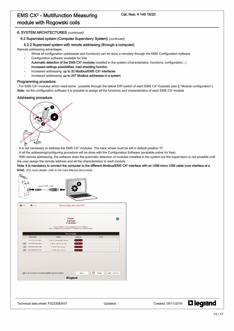
6.2.2 Supervised system with remote addressing (through a computer)
Remote addressing advantages:
- Whole of configuration (addresses and functions) can be done a remotely through the EMS Configuration software
- Configuration software available for free
- Automatic detection of the EMS CX3 modules installed in the system (characteristics, functions, configuration...)
- Increased settings possibilities: load shedding function
- Increased addressing: up to 32 Modbus/EMS CX3 interfaces
- Increased addressing: up to 247 Modbus addresses in a system
Programming procedure:
. For EMS CX3 modules which need some : possible through the lateral DIP-switch of each EMS CX3 modules (see § “Module configuration”).
Note: via the configuration software it is possible to assign all the functions and characteristics of each EMS CX3 module
Addressing procedure:
. It is not necessary to address the EMS CX3 modules. The track wheel must be left in default position “0”.
. A all the addressing/configuring procedure will be done with the Configuration Software (available online for free)
. With remote addressing, the software does the automatic detection of modules installed in the system but the supervision is not possible until
the user assign the remote address and all the characteristics to each module.
Note: it is mandatory to connect the computer to the different Modbus/EMS CX3 interface with an USB-micro USB cable (one interface at a
time). [For more details, refer to the User Manual Document]
Technical data sheet: F02335EN/01 Updated: - Created: 09/11/2016

14 / 17
EMS CX3 - Multifunction Measuring
module with Rogowski coils
Cat. Nos: 4 149 19/20
6. SYSTEM ARCHITECTURES (continued)
6.2 Supervised system (Computer Supervisory System) (continued)
6.2.2 Supervised system with remote addressing (through a computer) (continued)
Consequences for the system architecture:
- for 1 IP/Modbus gateway (cat. no 0 046 89):
o up to 247 Modbus address
o Because of Modbus: mandatory limit of max. 32 Modbus/EMS CX3 interfaces or max. 1000 m of Modbus cable (cable Belden 9842,
Belden 3106A or equivalent).
- for1 Modbus/EMS CX3 Interface (cat. no 4 149 40):
o up to 30 EMS CX3 modules or grouped modules (e.g. 30 devices grouped per functions with addresses from1 to 30)
It is possible to assign to several devices the same address with the purpose of grouping different functions, because they are related to the
same electrical circuit. For example it is possible to assign the same address to a signalling auxiliary module (cat. no 4 149 29), an universal
control module (cat. no 4 149 32), a measuring module, and so on. In this way on the EMS CX3 display or in a supervision system the grouped
function will be displayed as a unique “device” with all grouped functions. [Refer to the scheme up here]
Technical data sheet: F02335EN/01 Updated: - Created: 09/11/2016
Cat. no 0 046 89

15 / 17
EMS CX3 - Multifunction Measuring
module with Rogowski coils
Cat. Nos: 4 149 19/20
7. COMPLIANCE AND APPROVALS
Compliance to standards:
. Compliance with Directive on electromagnetic compatibility (EMC) n° 2004/108/EC
. Compliance with low voltage directive no. 73/23/CEE dated 19 February 1973, modified by directive no. 93/68/CEE dated 22 July
1993, modified by directive n° 2006/95/CE.
. Electromagnetic Compatibility:
emission according IEC/EN 61326-1, class B
immunity according IEC/EN 61326-1.
. Active energy accuracy class: 0,5 (Ea, IEC/EN 61557-12).
. Reactive energy accuracy class: 1 (Erv, IEC/EN 61557-12).
Conformity table to IEC 61557-12 Edition 1 (08/2007)
Performance measuring and monitoring devices (PMD) characteristics
Type of characteristic Specification values Other complementary characteristics
Power quality assessment function - -
Classification of PMD DD -
Temperature K55 -
Humidity + Altitude Standard conditions -
Active power and Active energy function performance class 0,5 -
Technical data sheet: F02335EN/01 Updated: - Created: 09/11/2016

16 / 17
EMS CX3 - Multifunction Measuring
module with Rogowski coils
Cat. Nos: 4 149 19/20
7. COMPLIANCE AND APPROVALS (continued)
Conformity table to IEC 61557-12 Edition 1 (08/2007) (continued)
Function symbols Function performance class
according to IEC 61557-12 Measuring range
Other complementary
characteristics
P 0,5 1,0 ÷ 63 A -
QA, QV 2 1,0 ÷ 63 A -
SA, SV 0,5 1,0 ÷ 63 A -
Ea 0,5 0 ÷ 2147483,648 MWh 1,0 ÷ 63 A
ErA, ErV 2 0 ÷ 2147483,648 MWh 1,0 ÷ 63 A
EapA, EapV - - -
f ± 0,01 Hz 45 ÷ 65 Hz -
I 0,5 1,0 ÷ 63A -
IN, INc 2 1,0 ÷ 63 A -
U 0,5 65 ÷ 290 V (Ph/N)
110 ÷ 500 V (Ph/Ph) -
PFA, PFV 1 0,5 ind ÷ 0,8 cap -
Pst, Plt - - -
Udip - - -
Uswl - - -
Utr - - -
Uint - - -
Unba 0.5 - -
Unb - - -
Uh 5 65 ÷ 290 V (Ph/N)
110 ÷ 500 V (Ph/Ph) -
THDu - 65 ÷ 290 V (Ph/N)
110 ÷ 500 V (Ph/Ph) -
THD-Ru 5 - -
Ih 5 1,0 ÷ 63 A -
THDi - 1,0 ÷ 63 A -
THD-Ri 5 - -
Msv - - -
Technical data sheet: F02335EN/01 Updated: - Created: 09/11/2016

17 / 17
EMS CX3 - Multifunction Measuring
module with Rogowski coils
Cat. Nos: 4 149 19/20
7. COMPLIANCE AND APPROVALS (continued)
Conformity table to IEC 61557-12 Edition 1 (08/2007) (continued)
Characteristics of "Power quality assessment functions"
Function symbols Function performance class
according to IEC 61557-12 Measuring range
Other complementary
characteristics
f ± 0,01 Hz 45 ÷ 65 Hz -
I 0,5 1,0 ÷ 63A -
IN, INc 0,5 1,0 ÷ 63 A -
U 0,5 65 ÷ 290 V (Ph/N)
110 ÷ 500 V (Ph/Ph) -
Udip - - -
Uswl - - -
Utr - - -
Uint - - -
Unba 0,5 - -
Unb - - -
Uh 5 65 ÷ 290 V (Ph/N)
110 ÷ 500 V (Ph/Ph) -
Ih 5 1,0 ÷ 63 A -
Msv - - -
Environment respect – Compliance with CEE directives:
. Compliance with Directive 2002/95/EC of 27/01/03 known as "RoHS" which provides for a restriction on the use of dangerous substances
such as lead, mercury, cadmium, hexavalent chromium and polybrominated biphenyl (PBB) and polybrominated diphenyl ether (PBDE)
brominated flame retardants from 1st July 2006
. Compliance with the Directive 91/338/EEC of 18/06/91 and decree
94-647 of 27/07/04.
. Compliant with regulation REACH
Plastic materials : . Halogens-free plastic materials.
. Marking of parts according to ISO 11469 and ISO 1043.
Packaging :
. Design and manufacture of packaging compliant to decree 98-638 of the 20/07/98 and also to directive 94/62/CE.
Environmental profile :
. PEP document available
Installation software :
. XL PRO3.
Technical data sheet: F02335EN/01 Updated: - Created: 09/11/2016