: -JoI CONTROL DOCUMENT COPY HOLDER LID …Milling@' operating mode, and is programmed according to...
35
, LcT;IEMENS : -JoI CONTROL DOCUMENT NO ?. : 1.2 $- COPY HOLDER LID LEVEL %q+ - .- .._ - ---- -__ . - l SINUMERIK 8T .Sprint 8T ’ Turning-/Milling Operation
Transcript of : -JoI CONTROL DOCUMENT COPY HOLDER LID …Milling@' operating mode, and is programmed according to...
, LcT ;IEMENS : -JoI
CONTROL DOCUMENT
NO ?. : 1.2 $-
COPY HOLDER LID
LEVEL %q+ - .- .._ - ---- -__ . -
l SINUMERIK 8T
.Sprint 8T
’ Turning-/Milling Operation
bj4386
, LcT : -JoI
bj4386
CONTROL DOCUMENT NO ?. : 1.2 $- COPY HOLDER LID LEVEL %q+ .._ - ---- -__ .
bj4386
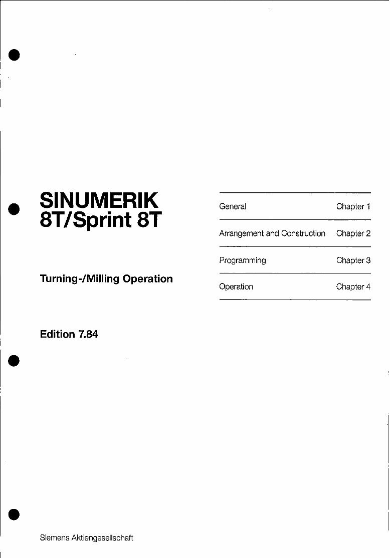
l SINUMERIK 8TBprint 8T
Turning-/Milling Operation
Edition 7.84
Siemens Aktiengesellschaft
General Chapter 1
Arrangement and Construction Chapter 2
Programming Chapter 3 ~
Operation Chapter 4
SINUMERIK 8T/Sprint 8T Drilling/Milling Operation O-l A.7.84
a 'SINUMERIK @ Documentation
Key to editions
The editions listed below have appeared previous to this latest edition.
Sections which have been modified with respect to the previous edition are marked.
a Edition Order no. Modifications
1.84 E80210-T2 7.84 E80210-T2-X-Al-7600 New edition

SINUMERIK 8T/Sprint 8T Drilling/Milling Operation O-2 A.7.84
CONTENTS
1. 1.1
2.
2.1
2.2
2.2.1
2.3
2.3.1
2.4
2.4.1
2.4.2
3.
3.1
3.2 3.2.1
3.2.2 3.2.3
3.3
3.3.1
3.3.2
3.4 3.4.1
3.4.2
‘4.
4.1 4.1.1
General
Using a lathe for turning and milling operations
Arrangement and construction
Drive and encoder, pulse evaluation for the C-axis
Arrangement of the operator's panel in the 8T/Sprint 8T for
turning/milling operation Switching over the operator's panel by the PC
Software switchover
Spindle encoder and setpoints during milling operation
Possible configuration of the axes
8T/Sprint 8T-Sprint 8M, with analog or digital position
control (MS 230/MS 250)
8T/Sprint 8T-Sprint 8M, with digital position control (MS 250)
Programming
General
G36/G37 coordinate transformation TRANSMIT
G37, coordinate transformation TRANSMIT selected
Programming with TRANSMIT
Application notes Program structure
Example on the structuring of a program
Program example
Handling tool offsets
Special case Using tool length compensation for eccentric cutters
with TRANSMIT
Operation
Display with G37/TRANSMIT Modification of the display system

SINUMERIK 8T/Sprint 8T Drilling/Milling Operation l-l A.7.84
a 1. General
a
The progress made in the automation of chip removing machine
tools has led to extensive optimization of the actual machining
times.
In spite of this however, during manufacturing many parts are
clamped onto a milling machine, where for example prismatic
surfaces or eccentric contours (external poW3ons, eccentrics,
flanges or cylinder grooves) are added after turning.
This results in a significant increase in the machining times due to the additional time required for loading, unloading, clamping
and in some cases aligning of the parts.
The control concept presented here eliminates this additional
time by combining the turning and milling operation on a single
machine which requires only one set-up. This results in a
significantly more cost effective total machining process.
This is achieved by a adding the milling operations listed below
to a turning machine:
. 3 D-Interpolation *
. Cylindrical interpolation
. Coordinate transformation TRANSMIT *
. Cutter radius compensation *
. Machining cycles (drilling and milling patterns) *
0
* Supplement

SINUMERIK 8T/Sprint 8T Drilling/Milling Operation l-2 A.'?.84
1.1 Using the lathe for turning and milling operations 0
Turning Milling
Setp. milling WV Dri.ve for milling sp.
Turning Milling
The characteristic features of a standard lathe are two linear
axes X and Z and a main spindle S. During the milling operation,
the missing Y axis is replaced by the main spindle drive, which
acts as an interpolating rotary axis C. The speed command value
defined by the S address is used in this case by the drive for
the milling head.
The machine can be switched over from turning to milling
operation and vice-versa by operator action or through
programming. Programming is carried out in the t'Turningt'
operating mode, according to the turning machine's programming
instructions. It offers the programming conveniences of a turning
machine control, such as diameter programming, cutter radius
compensation and standard turning cycles. When switching over to
milling operation, the functions of the main spindle are taken
over by rotary axis C which possesses interpolation capability.
The setpoint values defined under the address S are now
associated with the milling spindle. The control is now in the
l'Milling@' operating mode, and is programmed according to the
milling machine programming instructions. In this mode functions
such as 3D-linear interpolation, circular and helical
interpolation, milling and boring' patterns, cylindrical
interpolation and cutter radius compensation are available.
SINUMERIK 8T/Sprint 8T Drilling/Milling Operation 2-l A.7.84
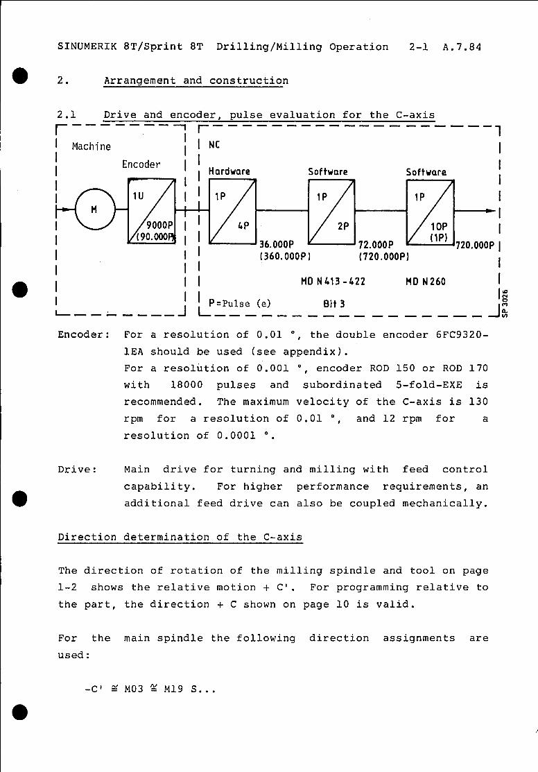
2. Arrangement and construction
2.1 Drive and encoder. pulse evaluation for the C-axis
r ------- 7 f.-- ---------- --------, 1
1 Machine I
i I NC I
Software
(36O.OOOP)
Software
(72O.OOOP)
I I MD N413-522 IICI N260
1 I I I P=Pulse (e) Bit 3
I I I I
-I I
72O.OOOP 1
I I ‘g
--L--,, -I I--------------,--, J $I
Encoder: For a resolution of 0.01 O, the double encoder 6FC9320-
1EA should be used (see appendix).
For a resolution of 0.001 O, encoder ROD 150 or ROD 170
with 18000 pulses and subordinated 5-fold-EXE is
recommended. The maximum velocity of the C-axis is 130
rpm for a resolution of 0.01 ', and 12 rpm for a
resolution of 0.0001 O.
Drive: Main drive for turning and milling with feed control
capability. For higher performance requirements, an additional feed drive can also be coupled mechanically.
Direction determination of the C-axis
The direction of rotation of the milling spindle and tool on page
l-2 shows the relative motion $ Cl. For programming relative to
the part, the direction + C shown on page 10 is valid.
For the main spindle the following direction assignments are
used:
-C’ i% MO3 % Ml9 S...
SINUMERIK 8T/Sprint 8T Drilling/Milling Operation 2-2 A.7.84
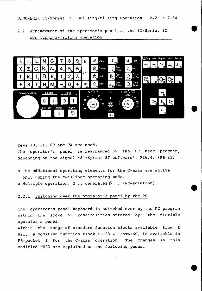
2.2 Arrangement of the operator's panel in the 8T/Sprint 8T
for turning/milling operation
Keys 10, 11, 67 and 74 are used.
The operator's panel is rearranged by the PC user program,
depending on the signal "8T/Sprint 8T-software", F26.4. (FB 23)
o The additional operating elements for the C-axis are active
only during the llMilling" operating mode.
o Multiple operation, % ., generates @ . (NC-solution)
2.2.1 Switching over the operator's panel by the PC
The operator's panel keyboard is switched over by the PC program
within the scope of possibilities offered by the flexible
operator's panel. Within the range of standard function blocks available from E
821, a modified function block FB 23 - TASTANNC, is available in
FB-packet 1 for the C-axis operation. The changes in this
modified FB23 are explained on the following pages.
SINUMERIK 8T/Sprint 8T Drilling/Milling Operation 2-3 A.7.84
FB 23: TASTANNC
Description
If the "flexible operator's panel" bit is set in the machine data
of the NC, then the signals of the standard keyboard and the keys
from the NC operator's panel are first transmitted to the PC.
These keyboard signals are returned to the NC in the normal case
bY the function block "Transmit keyboard signals to NC”.
Depending on the function for which the keyboard signals are
required in the PC, the transfer of the corresponding keys to the
NC is either suppressed or modified as described below:
Keys for input of display information:
The signals of these keys (addresses %, / etc .; digits 0,l etc.)
as well as the cursor keys are suppressed for the NC, if the
display is used by the PC or if the input SPT is "1". If SPT
is " 1" , the selection of the pictures "Test", "Parts program",
"Tool offset" and "Zero offset" is suppressed by the NC
operator's panel.
Keys for operating modes:
The signals from these keys (AUTO, JOG etc.) are suppressed, if
the operating modes are selected from the PC (e.g. for automatic
program start).
Selecting switch for spindle speed and feed / rapid traverse
override, direction keys and axis selection switch:
The signals are normally entered via the operator's panel of the
NC (Signal "0" at the inputs KPC and APC). Should these signals
be given by the PC (e.g. from a separate machine operator's
panel), then the corresponding signals must be entered directly
before calling FB23 in FW 248 and/or 250 and enabled via inputs
KPC/APC.

SINUMERIK 8T/Sprint 8T Drilling/Milling Operation 2-4 A.7.84
If DNC operation is active (interface flag 45.31, then the key DI/O is not transferred to the NC. Furthermore the RESET
pushbutton can,be disabled if the corresponding bit in the state
word (see assignment ZW) is set; RESET can then be entered from
the PC (also via one bit in the status word).
Oberation with the C-axis:
The control operates as far as the hardware is concerned only
with the operator's panel for SINUMERIK 8T. If the software on
the M-version is switched over (M26.5 = 01, then the keys and
switches are rearranged to an M-operator's panel.
SINUMERIK 8T/Sprint 8'1' Drilling/Milling Operation 2-5 A.7.84
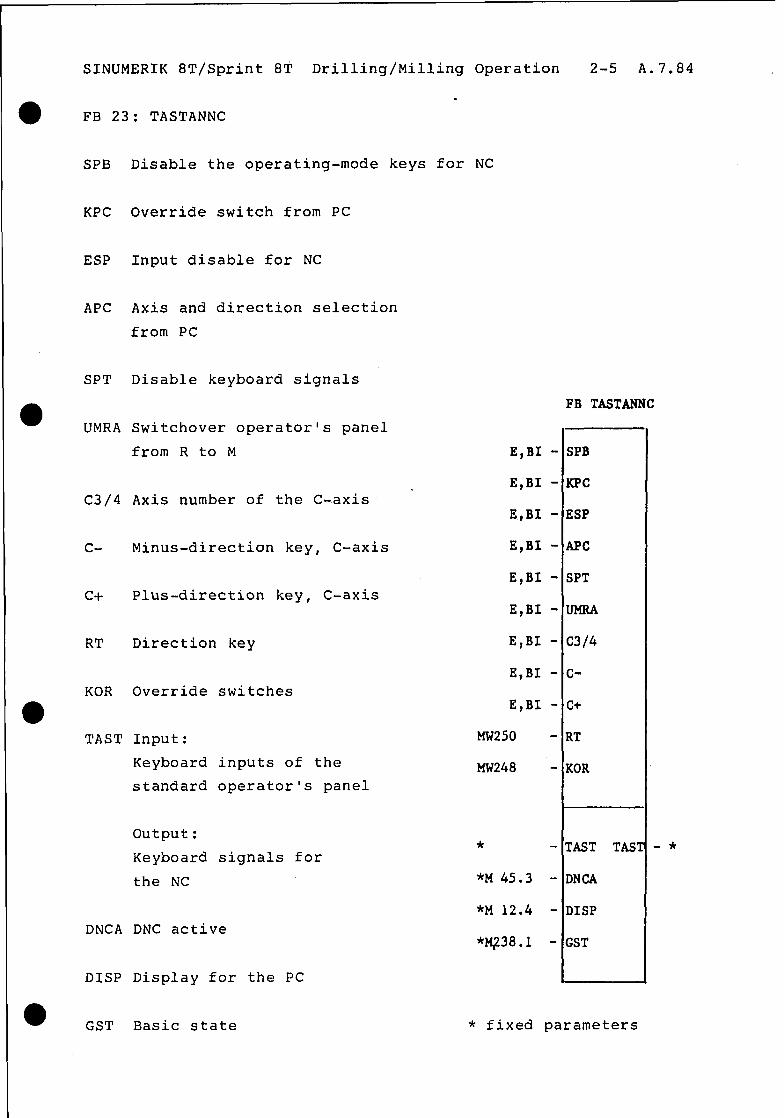
. FB 23: TASTANNC
SPB Disable the operating-mode keys for NC
KPC Override switch from PC
ESP Input disable for NC
APC Axis and direction selection
from PC
SPT Disable keyboard signals
FB TASTANNC
UMRA Switchover operator's panel
from R to M E,BI - SPB
KPC '
E,BI - C3/4 Axis number of the C-axis
E,,BI - ESP
c- Minus-direction key, C-axis E,Bl - APC
E,BI - SPT Cf Plus-direction key, C-axis
E,BI -
RT Direction key
KOR Override switches
TAST Input:
Keyboard inputs of the
standard operator's panel
E,BI - c3/4
E,BI - C-
E,BI - c+
MW250 - RT
Mw248 - KOR
output:
Keyboard signals for
the NC
DNCA DNC active
DISP Display for the PC
* * TAST TAST -
*t4 45.3 - DNCA
*M 12.4 - DISP
*M;L38.1 - GST
GST Basic state * fixed parameters
SINLJMERIK 8T/Sprint 8T Drilling/Milling Operation 2-6 A.7.84
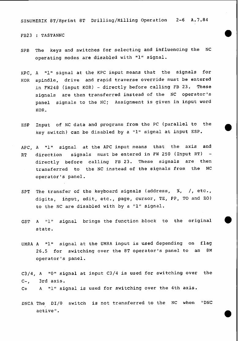
FB23 : TASTANNC
SPB The keys and switches for selecting and influencing the NC
operating modes are disabled with "1" signal.
KPC, A "1" signal at the KPC input means that the signals for
KOR spindle, drive and rapid traverse override must be entered
in FW248 (input KOR) - directly before calling FB 23. These
signals are then transferred instead of the NC operator's
panel signals to the NC; Assignment is given in input word
KOR.
ESP Input of NC data and programs from the PC (parallel to the
key switch) can be disabled by a llllt signal at input ESP.
APC, A "1 I, signal at the APC input means that the axis and
RT direction signals must be entered in FW 250 (Input RT) -
directly before calling FB 23. These signals are then
transferred to the NC instead of the signals from the NC
operator's panel.
SPT The transfer of the keyboard signals (address, %, /, etc.,
digits, input, edit, etc., page, cursor, TE, PP, TO and ZO)
to the NC are disabled with by a "1" signal.
GST A II 1 II signal brings the function block to the original
state.
UMRA A "1 II signal at the UMRA input is used depending on flag
26.5 for switching over the 8T operator's panel to an 8M
operator's panel.
C3/4, A "0" signal at input C3/4 is used for switching over the
c-t 3rd axis.
c+ A "1" signal is used for switching over the 4th axis.
DNCA The DI/o switch is not transferred to the NC when "DNC
active".
SINUMERIK 8T/Sprint 8T Drilling/Milling Operation 2-7 A.7.84
0 TAST A' tIO1' signal at input SPT causes the.keyboard inputs to be
continuously transferred to the NC. If the signal is "1 II
then they can be transferred from the PC.
D1SP.A II 0 II signal at input DISP is used for disabling the
transfer of those keyboard signals used for selecting or
modifying display information etc. (FB103-110,114), to the
NC.
l
SINUMERIK 8T/Sprint 8T Drilling/Milling Operation 2-8 A.7.84
2.3 Software switchover
A handshaking procedure across the NC-PC interface is used for
the switchover from turning to milling operation.
The PC switches the input signal F 01.2 "8T/Sprint 8T-Software".
The switchover is accepted by the NC only in the "RESET state"
(warning 511).
After switchover, the NC acknowledges with the output signal F
26.5.
NC-input: F01.2 = 0 = Sprint 8M-software
F01.2 = 1 = 8T/Sprint 8T-Software
NC-output: F26.5 = 0 = Sprint 8M-Software
F26.5 = 1 = 8T/Sprint 8T-Software
After the Sprint 8M is switched to 8T/Sprint 8T, the signal
"Reference point reached" for the axis to be switched over is
de-activated (The axis number of the switched axis is given by
machine datum 465 bits O-3).
2.3.1 Spindle encoder and setpoints during milling operation
Milling operation with the C-axis offers two possibilities
regarding the main spindle and the milling spindle:
a) Milling spindle without actual value detection
E.g. driven tool in revolver; the milling spindle receives the
setpoint from the NC, the NC however does not receive an
encoder feedback signal from the milling spindle, but from the
main spindle as for turning operation.
However since this is to be operated as a third axis under
position control, one must ensure that:
- the spindle alarms sometimes output by the NC to the PC are not
processed by the PC.
a
-

l
l
SINUMERIK 8T/Sprint 8T Drilling/Milling Operation 2-9 A.7.84
The speed setpoint for the main spindle is.switched over to the milling spindle, the main spindle is controlled by the position
setpoint of the 4th. (3rd.) axis. The actual value detection for the main spindle working as a C-axis is carried out by an additional encoder e.g. 9000 pulse-system of the double pulse generator 6FC9320-lEA, connected to the actual value input of the 4th. (3rd.) axis.
During milling operation (switching state 8T/Sprint 8~), the spindle setpoint of the NC is switched again to the main spindle.
The position setpoint of the C-axis is opened and the spindle position encoder (9000 pulse) which is still connected to
x211 of the measurement circuit module remains inactive during the milling state (8T/Sprint 8T).
b) Milling spindle with actual value detection
If high demands are made on the milling spindle, (e.g.oriented spindle stop M19, thread cutting), then the software switchover to Sprint 8M (milling operation) can be implemented by switching over spindle setpoints and actual values of the NC to the milling
spindle as shown in the following recommendation:
MS230 X202 (250)
' Main
spindle
I drive
L Milling spindle
r-l drive
MS230 X207 m (250)
L i --
MS 230 X211 8 (250)
lequirements: o The NC-internal spindle monitoring (machine data
Bit) is not activated.

SINUMERIK 8T/Sprint 8T Drilling/Milling Operation 2-10 A.7.84
o Closed-loop control of the milling spindle drive
o Additional spindle sensor on the milling spindle
(1024 pulses per revolution)
o Switchover electronics for sensor
SINUMERIK 8T/Sprint 8T Drilling/Milling Operation 2-11 A.7.84
TO
range TO input
in auto
TO tape
read/
punch
I Progr-
amming
Machine
progr.
8T op.
panel §Inout
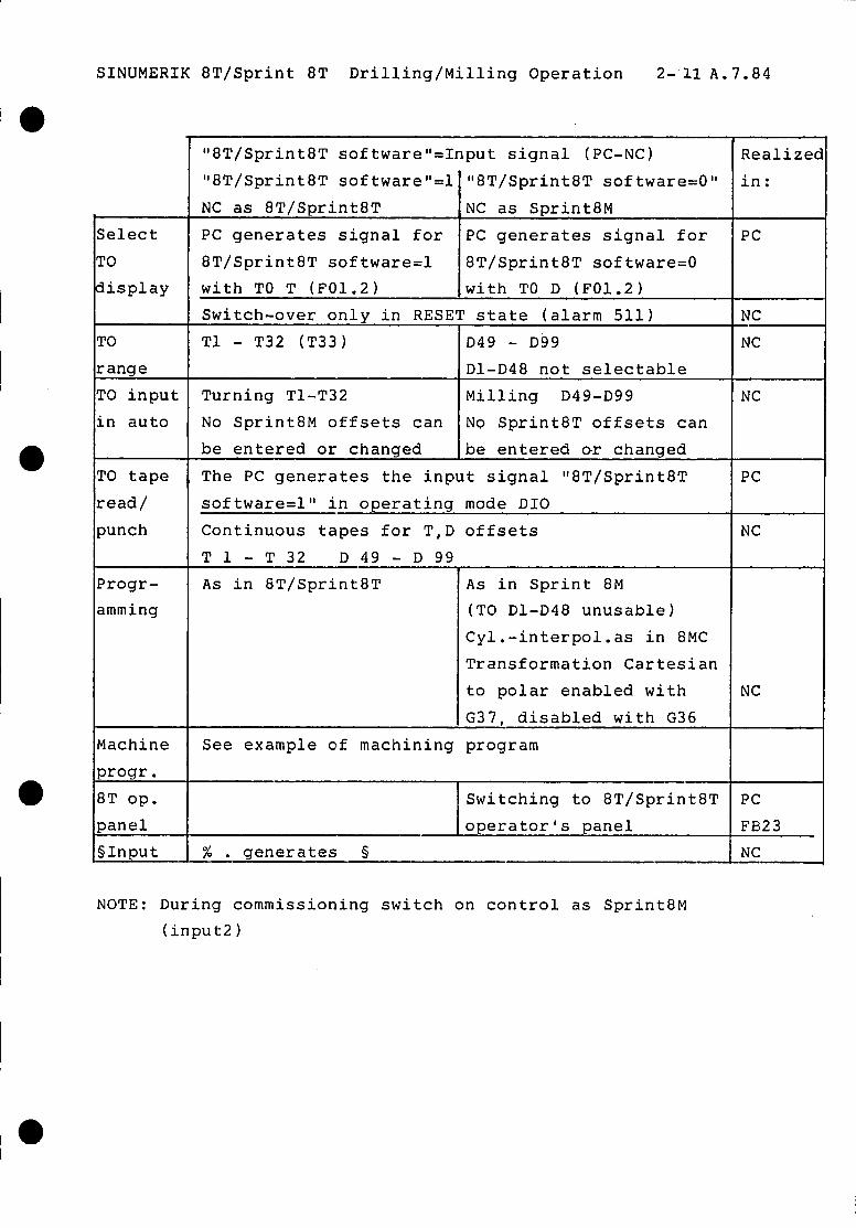
"8T/Sprint8T software "=Input signal (PC-NC) "8T/Sprint8T software I'=1 "8T/Sprint8T software=O"
NC as 8T/Sprint8T NC as Sprint8M
PC generates signal for PC generates signal for
8T/Sprint8T software=1 8T/Sprint8T software=0
with TO T (F01.2) with TO D (F01.2)
Switch-over only in RESET state (alarm 511)
Tl - T32 (T33) D49 - D99
Dl-D48 not selectable Turning Tl-T32 Milling D49-D99
No Sprint8M offsets can NQ SprintBT offsets can
be entered or changed be entered or changed
The PC generates the input signal "8T/Sprint8T
software=l" in operating mode DIO
Continuous tapes for T,D offsets
Tl - T 32 D 49 - D 99 - As in GT/Sprint8T
See example of machining program
As in Sprint 8M
(TO Dl-D48 unusable)
CYl .-interpol.as in 8MC
Transformation Cartesian
to polar enabled with
G37, disabled with G36
Switching to 8T/Sprint8T
operator's panel % . aenerates 5
Realizec
in:
PC
NC
NC
NC
PC
NC
NC
PC
FE323 NC
NOTE: During commissioning switch on control as Sprint8M
(input21
SINUMERIK 8T/Sprint 8T Drilling/Milling Operation 2-12 A.7.84
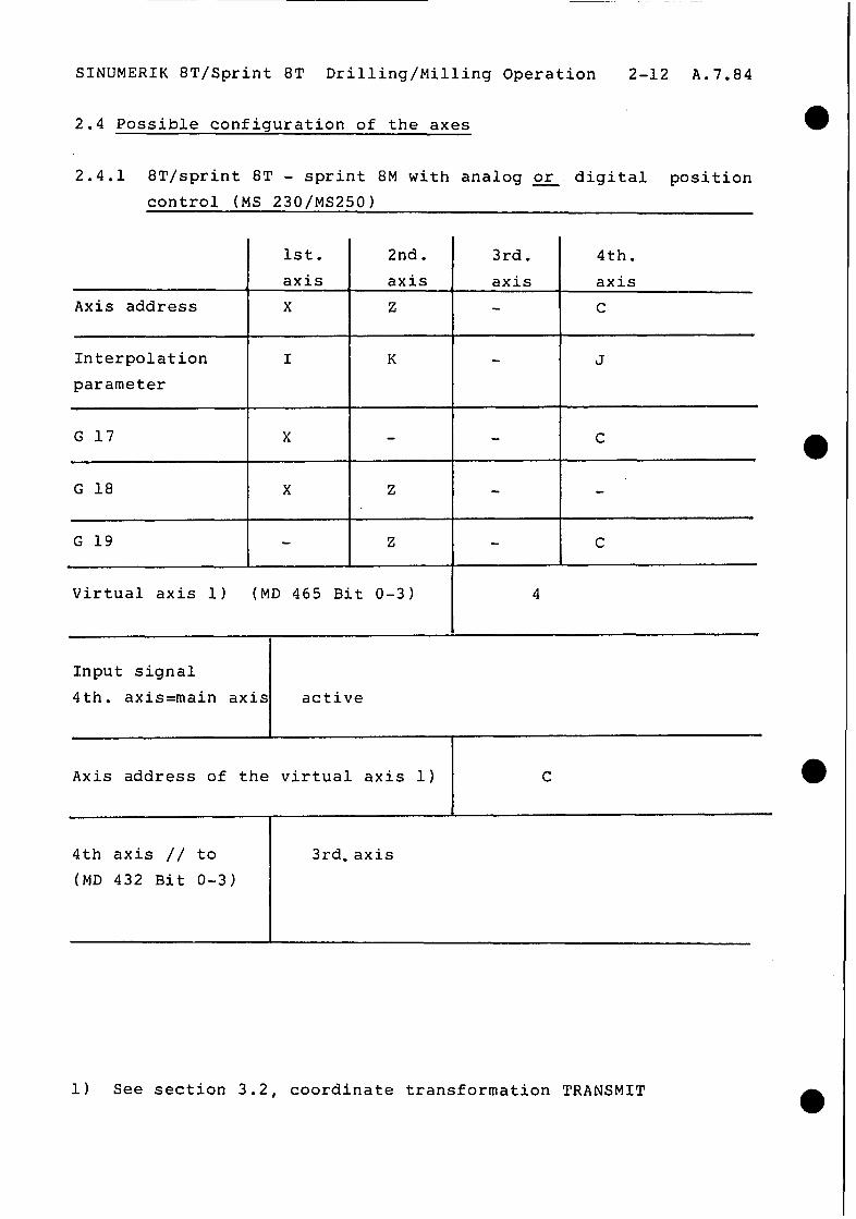
2.4 Possible configuration of the axes
2.4.1 8T/sprint 8T - sprint 8M with analog or digital position control (MS 230/MS250)
Axis address
1st.
axis
X
2nd. 3rd. axis , axis Z
Interpolation I K parameter
G 19 I Z I
4th.
axis
C
J
C 4
C
Virtual axis 1) (MD 465 Bit O-3) I I
4
Input signal
4th. axis=main axis active
Axis address of the virtual axis 1) C
4th axis // to
(MD 432 Bit O-3) 3rd.axis
1) See section 3.2, coordinate transformation TRANSMIT

SINUMERIK 8T/Sprint 8T Drilling/Milling Operation 2-13 A.7.84
l 2.4.2 8T/Sprint 8T-Sprint 8M, with digital position control (MS 250)
(alternative arrangement to 2.4.1)
Axis address
Interpolation
parameter
G 17
G 18
G 19
MD465/3
4th. axis
main axis
Axis address of the
virtual axis 1)
1st.
axis X
I
X
X
l 4th axis // to 3rd axis
(MD 432 Bit O-3)
2nd.
axis - z
K
Z
Z
L
3rd.
axis
C
J
C
C
3
4th.
axis
not active
C
--------------
1) See section 3.2, coordinate Transformation TRANSMIT

l

SINUMERIK 8T/Sprint 8T Drilling/Milling Operation 3-l A.7.84
0 3. Programming
3.1 General
Turning operations are programmed according to the 8T/Sprint 8T-
Programming Instructions.
Milling operations are programmed according to the Sprint 8M-
Programming instructions, using tool offsets D49 through D99.
A turning machine with its rotary C-axis (main drive), and a
linear X-axis is to be treated as a polar coordinate system when
programming. Especially in outer contour machining of turned
parts, this conceptual approach leads to the upgrading of the
numerical control so that in the case of milling operations it
can be treated as a milling machine as far as programming is
concerned, i.e. in a Cartesian coordinate system. Programming in
Cartesian coordinates and motion in polar coordinates requires
coordinate transformation.
The coordinate transformation allows, for instance, the
programming of an outside rectangle on a turning machine in four
NC blocks, as in any standard milling machine.
3.2 G36/G37, coordinate transformation "TRANSMIT"* For milling operation of the external contours of turned parts on
spot-faces (contouring operation linear axis plus rotary axis).
The TRANSMIT function (transformation milling into turning)
allows contour programming in a "virtual" Cartesian system, while
the motion of the machine occurs in a real polar coordinate
system. This virtual Cartesian coordinate system is constructed
from the 1st. axis X, and from the axis number of the
corresponding rotary axis, as designated under machine datum
465/Bit O-3. The rotary axis is given by address IIC" and the
virtual axis by the symbolical address "Cf". The transformation
is activated and de-activated within the program using the G-
function.
* Supplement

SINUMERIK 8T/Sprint 8T Drilling/Milling Operation 3-2 A.7.84
G36 Coordinate transformation de-activated
(Reset State)
The rotary axis is programmed in degrees, the velocity in degrees/min.
3.2.1 G37 Coordinate transformation TRANSMIT selected
Programming is carried out in the virtual Cartesian coordinate system. C is programmed in mm, the velocity in mm/min.
Cartesian 1

SINUMERIK 8T/Sprint 8T Drilling/Milling Operation 3-3 A.7.84
Application example: +x
/
Milling of a contour on the transverse plane
% 20 Program part milling *
*
NlOO GO 2200 CO
Coordinate transformation activated with G37
N105 G37 G42 D49 Xl00 Cl00 Gl F5000
Nllo X-100 FlOO
N115 C-100
N120 X+100
N125 Cl00
N130 G42 DO Xl10 Cl10 F5000
Coordinate transformation de-activated with G36
N135 G36 *
*

SINUMERIK 8T/Sprint 8T Drilling/Milling Operation 3-4 A.7.84
3.2.2 Programming with TRANSMIT
- The missing axis of the actual virtual plane is substituted
with G17, if only one axis is programmed in the block and if
this axis is an axis of the selected plane (example a and b).
- The control activates alarm 504 if only one axis of the
virtual plane and one axis not belonging to the virtual plane
are programmed (example c).
- Both axes of the virtual plane must be programmed, if further
axes, apart from the axes of this plane, are programmed in the
same block (example d).
Example: G37 active, X -
a) G17 X..
b) G17 Cf..
c) G17 X.. Z..
d) G17 X.. Cf.
e) G17 Z..
Note:
LIF
LIF
L,F
Z . .' LF
LIF
CF = virtual plane = G17 - plane
= Cf is substituted
= X is substituted
= Alarm 504
= No axis substituted
No alarm
= No alarm
The TRANSMIT function is also available for the SINUMERIK 8M. For
details see the programming instructions 8M/8MC/Sprint 8M,
edition 6/83. A software switch-over however, is only possible
between the 8T and the Sprint 8M.

SINUMERIK 8T/Sprint 8T Drilling/Milling Operation 3-5 A.7.84
3.2.3 Application notes:
- The cutter centre point must lie on the X-axis, at the turning
centre.
- The control cannot compensate for offsets in the Cf direction.
I - The part zero-point lies at the centre of the transverse axis.
- The transformation must not be switched on or off, if cutter
radius compensations G41/G42 are selected (change from G36 to
G37).
a - The transformation must not be switched on or off within a
contouring block sequence (change from G36 to G37).
- Inch to metric switching are not permitted within the x-Cf
system; the measurements must be entered in metric.
- Rapid traverse movements must be programmed under GO1 or Gll,
with the corresponding F-values.
- The contour velocity is programmed within the X-Cf coordinate
system and is held constant there. Only such X-Cf velocities
are permitted within a circle around the centre of the
0 traverse axis, which produce permissable C-axis angular
velocities. The motion is aborted if these limits are
exceeded.
- When changing from G36 to G37, the actual value of the C-axis
is set to 0 and the actual value of the X-axis is set to the
machine actual value regardless of the current offsets (ZO,
preset, G92). The zero offsets are calculated using the
Cartesian system.
- If the C-axis is used, the accuracy that can be achieved on
the part depends on the actual working radius (the control is
in degrees).
SINUMERIK 8T/Sprint 8T Drilling/Milling Operation 3-6 A.7.84
- If too1 change cycles L91/L92 are used. during the turning a operating mode, the tool length offsets of the milling tools used must also be stored in the T-geometry memory.
- Block advance with G37 blocks is not possible
3.3 Program structure
The part programs for the turning operations are clearly separated from those of the milling operations. By linking turning and milling operation programs, a total machining program is generated, and this is executed by a single activation (see
page 3-8). Within the part program, the programmer decides on the next program to be called. A M-function which can be freely selected at the beginning of a part program determines whether it
is a turning or a milling operation. The MO2 M-function
designates the end of a part program, while M30 indicates the end of the total machining program. This type of total machining program allows re-entry into any part program after a too1
break.

SINUMERIK 8T/Sprint 8T Drilling/Milling Operation 3-7 A.7.84
3.3.1 Example on the structuring of a program
NC-programming
%lOO(Machining program)
(Turning) Nl M71
N5 G.. G.. F.. X.. 2..
.
N245 %llO
N250 M70 MO2
5110 (Milling)
Nl M70
N2 L999 (or 531)
N260 G.. F.. Z.. C..
.
N525 %120
N530 M71 M02
%llO (Turning)
Nl M71
N540 G..G..F..Z..C..
.
N870 %lOO
N875 M30
PC-functions
* M70 - "RESET" * Signal "8T s/w"=0
* Op.panel 8T-Sprint8M
* C-axis not following
* Ref.pt.C-axis approach
* S-Betpoint to drive
* NC start
* M71 - "RESET"
* C-axis following
* Signal"8T s/w"=1
* op. panel Sprint8M-8T
* S-setpt.- main spindle
* NC start
* PC sets NC in reset
state by M30 without
M70/71
Notes
NC start from op.
* Next prog. no.
* Switchover 8T-
Sprint8M by M70
* Prog.%llO started
For program start
in reset state 8T
alarm 501 generated
without 531
* Next prog. no.
* Switchover Sprint
8M - 8T by M71 * Prog.%120 started
* Prog. no. of start
program
* End machining prog.
(30 w/o M70/71)
Any other optional M-functions can be used for M70/71

SINUMERIK 8T/Sprint 8T Drilling/Milling Operation 3-8 A.7.84
Total machining program
Turning operation
% 10
M71
N . . X.. Z.. *
N
%.ZO
X.. Z..
M70
MO2
Milling operation
% 20
M70
Q 31
N . . X.. Z.. C.. *
N. . x . . z . . c. .
% 30 M71
N . . x.. z.. *
Milling operation
% 30
M71
N . . X.. Z.. *
*
N . . X.. Z..
% 10
M 30
No. of the total machining program
Turning and milling
Switch on turning operation
No. of the next part program
End of the part program
No. of the part program
Switch on milling operation
No. of the part program
Switch on turning operation
No of the part program Switch on milling operation
No. of the total machining program
for the next run
End of the total machining program.
SINUMERIK 8T/Sprint 8T Drilling/Milling Operation 3-9 A.7.84
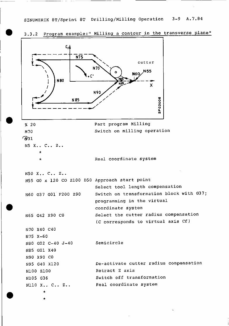
3.3.2 Program example:" Milling a contour in the transverse plane"
cutter
% 20 Part program Milling
M70 Switch on milling operation
N5 X.. C.. Z..
*
* Real coordinate system
N50 X.. C.. Z..
N55 GO x 120 CO ZlOO D50 Approach start point Select tool length compensation
N60 G37 GO1 F200 ZOO Switch on transformation block with G37;
programming in the virtual
coordinate system
N65 G42 X90 CO Select the cutter radius compensation
(C corresponds to virtual axis Cf)
l
N70 X40 C40
N75 X-60
N80 GO2 C-40 J-40
N85 GO1 X40
N90 X90 Co
N95 G40 X120
NlOO Zl0t-l
N105 G36
NllO X.. C.. Z..
*
*
Semicircle
De-activate cutter radius compensation
Retract Z axis
Switch off transformation
Real coordinate system

SINUMERIK 8T/Sprint 8T Drilling/Milling Operation 3-10 A.7.84
3.4 Handling tool offsets
The tool offsets for the turning and milling operations can be
stored simultaneously in separate memories of the control. For
turning operations, there are 33 offset memories available and
for milling operations there are 51 such memories. All too1
offsets can be punched out and read in at the same time. The operator can enter the tool wear even during machine operation.
* Tool tape format:
To generate a TO tape, it is necessary to first enter the 8T
offsets, and then the Sprint 8M offsets.
% TO
G92 TO1 X.. Z.. B.. A..
G92 T02 X.. Z.. B.. A.. *
*
G92 T31 X., Z.. B.. A..
G92 T32 X.. Z.. E.. A..
G92 D49 D.. E.. G92 D50 D.. B..
*
*
G92 D98 D.. B..
G92 D99 D.. F..
MO2
SINUMERIK 8T/Sprint 8T Drilling/Milling Operation 3-11 A.7.84
3.4.1 Special case
When operating with cutters in the X-C plane and with
transformation enabled, the following should be taken into
consideration:
- The reference point on the X-axis must be so defined, that the
cutter centre point always stays at X = 0.
- If the cutters used have different distances from the cutter
centre point to the tool reference point, then it is necessary
to define a different reference point for each cutter I 1.
The function "7 Additional reference points" should be used for
this purpose in the X-axis.
Example: The 1st cutter and the turning tools are related to
the 1st reference point (MD 180). If several cutters are to be
used, the 2nd cutter should be referenced to the 2nd point (MD
3001, the 3rd cutter to the 3rd point and so on rMD3Gl-tiD306).
In the part programs, the selection of reference points is done
by programming a T- or a M-word. The evaluation is carried out by
the PC which automatically generates a reference point approach
in the X-axis.
If several cutters with different distances of the cutter centre
point from the tool's reference point are used in the same
milling operation, then the milling program should be divided
into several part programs depending on the number of cutters
used, (because reference point approach is only possible in the
RESET state).
*) In these cases use of pitch error compensation or
software limit switches is not possible in the X-axis. After software version 03, see section 3.4.2.
SINUMERIK 8T/Sprint 8T Drilling/Milling Operation 3-12 A.7.84
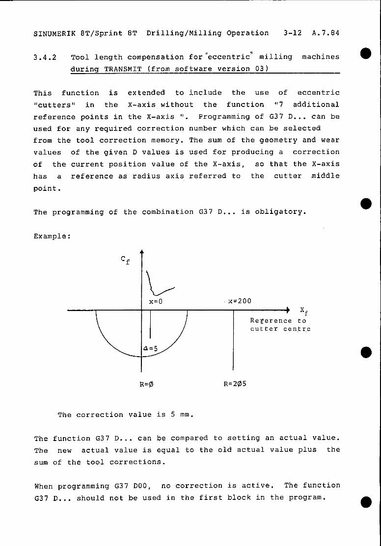
3.4.2 Tool length compensation for'eccentric'l milling machines
during TRANSMIT (from software version 03)
This function is extended to include the use of eccentric
"cutters" in the X-axis without the function "7 additional
reference points in the X-axis 'I. Programming of G37 D... can be
used for any required correction number which can be selected
from the tool correction memory. The sum of the geometry and wear
values of the given D values is used for producing a correction
of the current position value of the X-axis, so that the X-axis
has a reference as radius axis referred to the cutter middle
point.
The programming of the combination G37 D... is obligatory.
Example:
Rererence to cutter centr.e
R=@ R=2$35
The correction value is 5 mm.
The function G37 D... can be compared to setting an actual value.
The new actual value is equal to the old actual value plus the
sum of the tool corrections.
When programming G37 DOO, no correction is active. The function
G37 D... should not be used in the first block in the program.

SINUMERIK 8T/Sprint 8T Drilling/Milling Operation 3-13 A.7.84
0 4. Operation
Tool offset input in automatic operation:
No sprint 8M offsets can be entered or changed during turning
operations.
During milling operations, no 8T/Sprint 8T offsets can be entered
or changed.
If G37 is selected, then switchover is possible from AUTOMATIC
into the following operating modes:
a - Manual (JOG)
- Step (INC) - MD1
The C-axis is used for the duration of the switchover as a rotary
axis again. When this axis is traversed, the traversing path
appears in the display picture under OFF.
This path must be exactly traversed to zero before switching back
to AUTOMATIC.
4.1 Display for G37/TRANSMIT:
l ACT X.. (11.. (mm) DIF X.. (21.. (mm) Z . . (l).. (mm) Z . . (31.. (mm)
C . . (11.. (0) C . . (21.. (mm)
(1) Actual value in the real system
(2) Setpoint to actual value difference in the virtual
Cartesian system
(3) Setpoint to actual difference in the real system
Display of the actual value system referred to the workpiece is
not possible.

.SINUMERIK 8T/Sprint 8T Drilling/Milling Operation 3-14 A.7.84
4.1.1 Modification of the disolav svstem (from software version 03)
Display of the actual values can optionally be carried out using setting data in the real machine system (SE 2, Bit 3 =l)or in
the virtual Cartesian system.
The following example applies for the virtual Cartesian system
(SE 3, Bit 3 = 0).
Display of G37/TRANSMIT
ACT X... (21.. (mm) DIF X... (41.. (mm)
Z . . . (11.. (mm) Z . . . (31.. (mm)
C . . . (21.. (degree) C... (41.. (mm)
(1) Actual value in the real system
(2) Actual value in the virtual Cartesian system
(3) Setpoint actual value difference in the real system
(4) Setpoint actual value difference in the virtual Cartesian system
The display of the actual value system referred to the workpiece
is possible.

Herausgegeben von Siemens AG, Bereich Steuerungs- und Automatisierungstechnik Postfach 3240,. 8520 Erlangen
Siemens Aktierigesellschaft Subject to change without prior notice Order No. E-60210~T2-X-Al-7600 Printed in the Fed. Rep. of Germany 062 144 PA 0964.5