, De Luca, F., & Verderame, G. M. (2016). Ductility of ...beams (section 3), and (ii) a...
33
Gómez-Martínez, F., Alonso-Durá, A., De Luca, F., & Verderame, G. M. (2016). Ductility of wide-beam RC frames as lateral resisting system. Bulletin of Earthquake Engineering, 14(6), 1545–1569. https://doi.org/10.1007/s10518-016-9891-x Peer reviewed version Link to published version (if available): 10.1007/s10518-016-9891-x Link to publication record in Explore Bristol Research PDF-document The final publication is available at Springer via http://dx.doi.org/10.1007/s10518-016-9891-x. University of Bristol - Explore Bristol Research General rights This document is made available in accordance with publisher policies. Please cite only the published version using the reference above. Full terms of use are available: http://www.bristol.ac.uk/pure/about/ebr-terms
Transcript of , De Luca, F., & Verderame, G. M. (2016). Ductility of ...beams (section 3), and (ii) a...
Gómez-Martínez, F., Alonso-Durá, A., De Luca, F., & Verderame, G. M.(2016). Ductility of wide-beam RC frames as lateral resisting system.Bulletin of Earthquake Engineering, 14(6), 1545–1569.https://doi.org/10.1007/s10518-016-9891-x
Peer reviewed version
Link to published version (if available):10.1007/s10518-016-9891-x
Link to publication record in Explore Bristol ResearchPDF-document
The final publication is available at Springer via http://dx.doi.org/10.1007/s10518-016-9891-x.
University of Bristol - Explore Bristol ResearchGeneral rights
This document is made available in accordance with publisher policies. Please cite only the publishedversion using the reference above. Full terms of use are available:http://www.bristol.ac.uk/pure/about/ebr-terms
DUCTILITY OF WIDE-BEAM RC FRAMES AS LATERAL RESISTING SYSTEM
Fernando Gómez-Martínez*1,2, Adolfo Alonso-Durá2, Flavia De Luca3, Gerardo M. Verderame1
1Department of Structures for Engineering and Architecture, DIST, University of Naples Federico II,
Via Claudio, 21, 80125 Naples, Italy 2Department of Mechanics of the Continuum Media and Theory of Structures, Polytechnic University of
Valencia, Camino de Vera, s/n, 46022 Valencia, Spain 3Department of Civil Engineering, University of Bristol, Queen’s Building University Walk, BS8 1TR,
Bristol, UK
ABSTRACT
Some Mediterranean seismic codes consider wide-beam reinforced concrete moment resisting frames
(WBF) as horizontal load carrying systems that cannot guarantee high ductility performances.
Conversely, Eurocode 8 allows High Ductility Class (DCH) design for such structural systems. Code
prescriptions related to WBF are systematically investigated. In particular, lesson learnt for previous
earthquakes, historical reasons, and experimental and numerical studies underpinning specific
prescriptions on wide beams in worldwide seismic codes are discussed. Local and global ductility of
WBF are then analytically investigated through (i) a parametric study on chord rotations of wide beams
with respect to that of deep beams, and (ii) a spectral-based comparison with conventional reinforced
concrete moment resisting frames (i.e., with deep beams). Results show that the set of prescriptions given
by each modern seismic code provides sufficient ductility to WBF designed in DCH. In fact, global
capacity of WBF relies more on the lateral stiffness of the frames and on the overstrength of columns
rather than on the local ductility of wide beams, which is systematically lower with respect to that of deep
beams.
KEYWORDS: Wide beams, deep beams, seismic codes, effective width, behaviour factor, chord rotation,
ductility, effective period
1. INTRODUCTION
In Mediterranean countries, wide-beam reinforced concrete moment resisting frames
(WBF) are a common structural solution for both code conforming and non-conforming (“sub-
standard”) buildings in low-to-moderate seismic prone areas (Arslan and Kormaz, 2007; Vielma
et al., 2010; Benavent-Climent and Zahran, 2010; Inel et al., 2013; De Luca et al., 2014; López-
* Corresponding author: [email protected]
2
Almansa et al., 2013; Domínguez et al., 2014, 2016). On the other hand, such widespread
employment of wide beams (WB) instead of conventional deep beams (DB) in seismic regions is
more justified by architectural requirements rather than by a broad understanding of their
structural behaviour – sometimes considered as intermediate between a common frame and flat-
slab system (Benavent-Climent, 2007). The employment of WBF can be interpreted as a
convenient adaptation of gravity-load systems for low-seismic hazard areas. Moreover, the flat
bottom surface is flexible from an architectural point of view and it decreases construction costs
by savings in the formwork (Donmez, 2013).
Given the multiple uncertainties concerning WBF performances, traditionally, seismic
codes have been quite cautious in allowing their use with the same design rules of deep-beam
frames (DBF). Typical restrictions for WBF are the imposition of reduced design behaviour
factors (q), or even to prevent their use in seismic high-hazard areas. Nevertheless, different
experimental and analytical studies regarding seismic performances of wide beam–column
connections concluded that, if some basic design rules are taken into account, local performance
of WBF connections may be as satisfactory as that of DBF (see section 3). Therefore, more
recently, current international benchmark seismic codes, such as European Eurocode 8 part 1 –
EC8— (CEN, 2004), American ACI 318-08 (ACI, 2008) or New Zealander NZS 3101 (NZS,
2006) do not present any restriction for WBF as high ductility systems. However, some national
seismic codes in the Mediterranean area still do so, such as Spanish NCSE-02 (CDSC, 2002),
Italian NTC (CS.LL.PP, 2009) or Greek EAK 2000 (MEPP, 2000a) (see section 2).
The discussion herein is aimed at providing a suitable mechanical interpretation of the
restrictions on WBF in Mediterranean codes (section 2) through the examination of experimental
background. Local and global ductility of WBF are then analytically investigated through (i) a
parametric study on curvatures and chord rotations of wide beams with respect to that of deep
beams (section 3), and (ii) a spectral-based comparison with conventional DBF (section 4).
Finally, the analytical results of this study are summarized and conclusions on high ductility
WBF are drawn (section 5).
2. CODE DESIGN PROVISIONS FOR WIDE BEAMS
EC8 have been influencing European National codes for the last ten years, and often
European countries have adopted it through the release of National Annexes. However, some
3
differences can still be found with respect to design rules on WBF in codes of some
Mediterranean countries such as Italy –NTC—, Spain –NCSE-02—, Turkey –TSI (MPWS,
2007)—, and Greece –EAK 2000—.
Some of the following typical restrictions on WBF can be found in Mediterranean codes:
- it cannot be the only lateral resisting system in the building;
- it cannot be designed as High Ductility Class (DCH) system;
- wide beam–column connections must satisfy geometric and mechanical limitations.
It is not clear whether the above restrictions respond to specific mechanical models based
on analytical or experimental results or they are just conservative legacies from old construction
practice. They can be either based on the behaviour observed in flat-slab frames (NZS, 2006;
Fardis, 2009), which show scarce local and global ductility; i.e., due to punching shear failure or
to the difficulty to ensure capacity design of columns, respectively.
In the following, it is carried out a general review of the limitations provided by
Mediterranean codes on WBF compared to other international codes: EC8; ACI 318-08
complemented with ACI 352R-02 (ACI-ASCE, 2002) and ASCE/SEI 7-10 (ASCE, 2010); and
NZS 3101 (NZS, 2006) complemented with NZS 1170.5 (NZS, 2004). All the specific
prescriptions are summarised in Table 1.
2.1 Code provisions for flat-slab frames
Before going through a review of WBF code provisions, it is necessary to have an
overview of what codes provide for flat-slab structures. In fact, most of the rules on WBF often
look like an adaptation of flat-slab restrictions. Past versions of ACI 318 (ACI, 1989) prescribed
to avoid flat-slab structures unless they were coupled with shear walls as lateral load carrying
system. Current codes still provide severe restrictions to flat-slab employment with respect to
three main aspects: (i) site-hazard, (ii) deformability, and (iii) ductility.
Regarding site-hazard, only EC8 and TSI recommend not to use flat slab as “primary
seismic” elements when the design peak ground acceleration (PGA) is higher than 0.08g and
0.20g, respectively. In particular, TSI limit applies to flat slab systems without walls, considered
as systems of nominal ductility level (see Table 1).
Regarding deformability, modern codes set acceptable values for interstorey drift ratio
(IDR) –aimed at designing to Damage Limitation Limit State (DLS)— regardless of the
structural system considered, but still some codes, such as NZS 3101, provide more restrictive
4
IDR limitations for flat-slab structures (see Table 1). Other codes present qualitative limitations
for the deformed shape. In Greek EAK 2000, typical frame internal forces (i.e., opposite bending
moments at the two ends of members) are required for columns in flat-slab structures, to be
achieved through a sufficient stiffness of beams; otherwise, the lateral load carrying system has to
be shear walls. Moreover, other codes limit the overall height of the building when flat slab is the
only resisting system, e.g., 13m for TSI and 10m or three storeys for the Iranian seismic code
(BHRC, 2004). Regarding ductility, most codes do not allow considering flat-slab systems as
DCH system, and consequently they cap the maximum q (see Table 1).
On the other hand, codes do not explicitly clarify if behaviour and design of one-way
slabs (which is very often used in conjunction with WB) can be assimilated to flat slabs rather
than to WB; neither is it explicitly clarified whether the same effective widths are required for
reinforcement arrangements near the columns. NCSE-02 is the only code establishing explicitly
that one-way joist slabs, waffle slabs, and flat solid slabs shall be treated similarly to beams
concerning all the prescriptions referred to geometry and reinforcement arrangements.
2.2 Code provisions for wide-beam frames
Similarly to flat-slab structures, both American ACI 352R-91 (ACI-ASCE, 1991) and
Spanish NCSR-94 (CDSC, 1994) standards, in 1990s', limited the employment of WBF in
seismic regions: ACI 352R-91 recommended not using them, while NCSR-94 allowed the
employment up to 0.16g.
In recent years, almost all the codes have removed any limitation to the use of WBF as the
only lateral resisting system. However, some current codes still make it almost impossible: EAK
2000 imposes the same rules than for flat-slab frames regarding deformed shape, while NZS
3101 requires so large values of hb/ϕc (being hb the beam depth and ϕc the maximum diameter of
column bars) that the use of WB becomes not viable (hb usually larger than 40cm).
Regarding limitations for the design ductility class, current Spanish and Italian national
codes prevent WBF from being a high ductility system. Spanish NCSE-02 applies 50% reduction
of q downgrading WBF to Low Ductility Class (DCL), so that q ends to 2.0. Italian NTC applies
a 33% reduction, so that q becomes 3.90, corresponding to Medium Ductility Class (DCM). The
Italian restriction is more surprising than that of Spanish code; in fact, NTC is a local
arrangement of EC8, while NCSE-02 differs in many basic aspects with respect to EC8 (Gómez-
Martínez et al., 2015a,b). It is worth noting that, generally, international standards (such as EC8)
5
do not relate ductility to structural typologies but more to design requirements, progressively
relaxed from high to medium and low ductility classes (e.g., minimum dimensions, minimum
reinforcements, local ductility, axial load limitation, capacity design rules…). However, the
limitations for DCL provided by NCSE-02 are more severe than those provided by other codes.
Nevertheless, most of seismic standards, rather than limiting explicitly the employment of
WBF, establish geometrical restrictions to wide beam–column (WB–C) connections as condition
for the application of typical design procedures (Table 1 and Fig. 1). These restrictions are meant
to ensure the stress transfer within WB–C connections; otherwise, full capacity of beams cannot
be exploited.
The effective width of a beam is the fraction of the total width which satisfies flexural
equilibrium of forces when framing a narrower column within a connection. Current codes
provide maximum values to beam width (bw) in order to make it agree with the effective width.
Furthermore, some limits on the amount of top reinforcement to be placed within the width of the
beam or in the upper slab flange, as well as some definitions of effective width for other
mechanisms (shear equilibrium of beam and joint panel), underpin the same basic principles.
Other geometrical restrictions are oriented to ensure adequate bond behaviour of the longitudinal
reinforcement; this is the case of lower limits to members’ depths.
Code prescriptions regarding bw rely on different approaches, as shown in detail in Table
1, where maximum values of w (the “outer” part of bw at each side of the column) are shown
aimed at homogenisation with other provisions. Most codes forbid to design bw larger than a
specific limit, while others permit any bw as long as the reinforcement required to satisfy flexural
demand is placed within effective width (as in NZS 3101, NCSE-02 and somehow EC8). The
above limitations are usually not mandatory for DCL except for some codes (e.g. NCSE-02 and
NTC). The evaluation of the effective width is made on the basis of other dimensions; according
to NZS 3101, ACI 318-08 and Greek EKOS 2000 (MEPP, 2000b), it depends on column depth
(hc), while the rest of codes relate effective width to hb. EAK 2000, TSI, NTC, EC8 and ACI 318-
08 limit bw also on the basis of column width (bc). Furthermore, NZS 3101, NCSE-02 and ACI
318-08 provide explicit rules for the case of edge beams. The most severe restriction is given by
NCSE-02: all the upper and bottom reinforcement must be placed within the column core unless
transverse beams are present. Conversely, the most relaxed rule seems to be in EC8: placing the
reinforcement within the effective width is only an option in order “to take advantage of the
6
favourable effect of column compression on the bond of horizontal bars passing through the
joint”; however it is extensively considered as compulsory in the practice (Benavent-Climent et
al., 2010; Fadwa et al., 2014)
Other prescriptions ask for a specific amount of upper WB reinforcement to be placed
within the column core (i.e. passing through bc). This kind of prescriptions differs significantly
among different codes (see Table 1). It is worth noting that NZS 3101 requirement is not referred
to the column core but to the effective width, and the remaining 10% of reinforcement can be
placed within the upper slab effective width.
The eccentricity between the axis of the beam and that of the column is often limited. In
the case of edge beams (see Table 1), this requirement indirectly limits bw, being in most cases
consistent with the effective width limitation. NTC is the only code that allows higher
eccentricities if proper reinforcement is placed in the perpendicular direction.
Codes in which bw limitation is referred to the web or to the gross section might assume
implicitly bw to be the effective width for both flexure and shear. Conversely, NCSE-02 considers
that shear is able to be equilibrated at joint face only within the column core, providing a
conceptual difference from flexure and shear effective width.
Some codes also establish an explicit minimum value for beam depth hb≥30cm, as Iranian
code and TSI, which also relates minimum depth to the thickness of the upper slab (see Table 1).
Code restrictions regarding contribution of the upper slab to the flexural performance can
be divided in two groups: restrictions depending only on the local geometry of the connections,
and those depending also on the beam span. Some codes, for sake of conservativeness, propose
different magnitudes depending on the purpose of the evaluation: lower values for flexural design
of the beam, and higher values for assessing maximum flexural capacity of beams for capacity
design of columns and joints. Such codes always refer to the effectiveness of tensioned
reinforcement, and there is no mention to the compressive behaviour. It is not clear how to
account for the contribution of the upper slab in the case of WBF. In fact, when no transverse
beam is present, WB’s web or longitudinal reinforcement can be wider than the column, but none
of the upper reinforcement placed outside the column core may be effective according to the
upper slab tensioned flange restriction. ACI 352R-02 is the only code requiring torsional
evaluation of the transverse beam subjected to the action induced by the upper slab bars within
the effective slab width.
7
Regarding effective shear width of WB–C joint, NZS 3101, NTC and EC8 establish that it
may be higher than the strict volume contained within the intersection of members (i.e. larger
than the joint panel).
Finally, NZS 3101, NTC, EC8 and ACI 318-08 provide upper limits to the diameters of
longitudinal bars of beams with respect to hc aimed at proper bond behaviour within connections.
These limitations make it difficult to reduce significantly column sections at upper storeys.
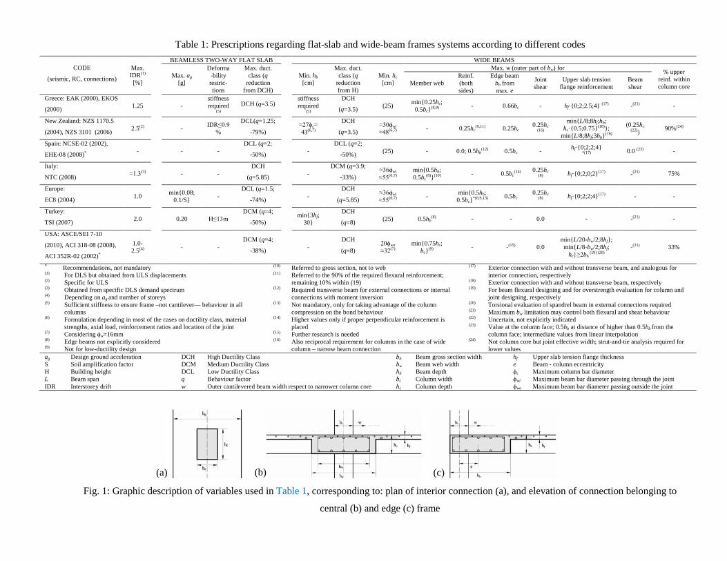
Table 1: Prescriptions regarding flat-slab and wide-beam frames systems according to different codes
CODE
(seismic, RC, connections)
Max. IDR(1) [%]
BEAMLESS TWO-WAY FLAT SLAB
WIDE BEAMS
Max. ag [g]
Deforma-bility restric-tions
Max. duct. class (q
reduction from DCH)
Min. hb [cm]
Max. duct. class (q
reduction from H)
Min. hc [cm]
Max. w (outer part of bw) for % upper reinf. within column core Member web
Reinf. (both sides)
Edge beam bb from max. e
Joint shear
Upper slab tension flange reinforcement
Beam shear
Greece: EAK (2000), EKOS
(2000) 1.25 - stiffness required
(5) DCH (q=3.5)
stiffness required
(5)
DCH
(q=3.5) (25) min{0.25hc; 0.5bc}(8,9) - 0.66bc - hf·{0;2;2.5;4} (17) -(21) -
New Zealand: NZS 1170.5
(2004), NZS 3101 (2006) 2.5(2) - IDR≤0.9%
DCL(q=1.25;
-79%) ≈27ϕc≈ 43(6,7)
DCH
(q=3.5) ≈30ϕwi ≈48(6,7) - 0.25hc
(9,11) 0.25hc 0.25hc
(16)
min{L/8;8hf;hb; hc·{0.5;0.75}(18)};
min{L/8;8hf;3hb}(19)
(0.25hc (22)) 90%(24)
Spain: NCSE-02 (2002),
EHE-08 (2008)* - - - DCL (q=2;
-50%) - DCL (q=2;
-50%) (25) - 0.0; 0.5hb(12) 0.5bc - hf·{0;2;2;4}
*(17) 0.0 (23) -
Italy:
NTC (2008) ≈1.3(3) - - DCH
(q=5.85) - DCM (q=3.9;
-33%) ≈36ϕwi ≈55(6,7)
min{0.5hb; 0.5bc
(8)}(10) - 0.5bc(14) 0.25hc
(8) hf·{0;2;0;2}(17) -(21) 75%
Europe:
EC8 (2004) 1.0 min{0.08; 0.1/S} -
DCL (q=1.5;
-74%) - DCH
(q=5.85) ≈36ϕwi ≈55(6,7) - min{0.5hb;
0.5bc}*(8,9,13) 0.5bc 0.25hc
(8) hf·{0;2;2;4}(17) - -
Turkey:
TSI (2007) 2.0 0.20 H≤13m DCM (q=4;
-50%) min{3hf;
30}
DCH
(q=8) (25) 0.5hb(8) - - 0.0 - -(21) -
USA: ASCE/SEI 7-10
(2010), ACI 318-08 (2008),
ACI 352R-02 (2002)*
1.0-2.5(4) - -
DCM (q=4;
-38%) - DCH
(q=8) 20ϕwo ≈32(7)
min{0.75hc; bc}(9) - -(15) 0.0
min{L/20-bw/2;8hf}; min{L/8-bw/2;8hf;
hc}≥2bb (19) (20)
-(21) 33%
* Recommendations, not mandatory (1) For DLS but obtained from ULS displacements (2) Specific for ULS (3) Obtained from specific DLS demand spectrum (4) Depending on ag and number of storeys (5) Sufficient stiffness to ensure frame –not cantilever— behaviour in all
columns (6) Formulation depending in most of the cases on ductility class, material
strengths, axial load, reinforcement ratios and location of the joint (7) Considering ϕw=16mm (8) Edge beams not explicitly considered (9) Not for low-ductility design
(10) Referred to gross section, not to web (11) Referred to the 90% of the required flexural reinforcement;
remaining 10% within (19) (12) Required transverse beam for external connections or internal
connections with moment inversion (13) Not mandatory, only for taking advantage of the column
compression on the bond behaviour (14) Higher values only if proper perpendicular reinforcement is
placed (15) Further research is needed (16) Also reciprocal requirement for columns in the case of wide
column – narrow beam connection
(17) Exterior connection with and without transverse beam, and analogous for interior connection, respectively
(18) Exterior connection with and without transverse beam, respectively (19) For beam flexural designing and for overstrength evaluation for column and
joint designing, respectively (20) Torsional evaluation of spandrel beam in external connections required (21) Maximum bw limitation may control both flexural and shear behaviour (22) Uncertain, not explicitly indicated (23) Value at the column face; 0.5hb at distance of higher than 0.5hb from the
column face; intermediate values from linear interpolation (24) Not column core but joint effective width; strut-and-tie analysis required for
lower values ag S H L IDR
Design ground acceleration Soil amplification factor Building height Beam span Interstorey drift
DCH DCM DCL q w
High Ductility Class Medium Ductility Class Low Ductility Class Behaviour factor Outer cantilevered beam width respect to narrower column core
bb bw hb bc hc
Beam gross section width Beam web width Beam depth Column width Column depth
hf e ϕc ϕwi ϕwo
Upper slab tension flange thickness Beam - column eccentricity Maximum column bar diameter Maximum beam bar diameter passing through the joint Maximum beam bar diameter passing outside the joint
Fig. 1: Graphic description of variables used in Table 1, corresponding to: plan of interior connection (a), and elevation of connection belonging to
central (b) and edge (c) frame
(a) (b) (c)
3. EXPERIMENTAL BEHAVIOUR AND ANALYTICAL MODELS OF WBF
Experimental tests on WB and WBF have been representing the benchmark for changes
and improvements to codes in the last decades. Several cyclic tests on subassemblages
representing WB–C connections have been carried out (Gentry and Wight, 1992; LaFave and
Wight, 1997; Quintero-Febres and Wight, 1997; Siah et al., 2003; Benavent-Climent, 2007;
Benavent-Climent et al., 2009 and 2010; Li and Kulkarni, 2010, Masi et al., 2013a and 2013b;
Fadwa et al., 2014). All these studies capture different conditions (e.g., interior or exterior
connections, presence of upper slab, axial load on columns, vertical load on beams, or transverse
deep beams). Furthermore, post-earthquake damage scenarios in the Mediterranean area have
shown different in-field performance of WBF with respect to that of DBF. For instance, plastic
hinges in beams and damage in joints are quite rarely observed (e.g., Donmez, 2013; Gómez
Martínez et al., 2015a).
Aimed at shedding some light on code provisions, a review of experimental and analytical
studies and original mechanic and analytical considerations on WBF are provided herein. The
study is carried out in three main steps, from local to global performances, in analogy with the
main three drawbacks characterizing WBF with respect to DBF (Benavent et al., 2010): (i)
deficient beam–column stress transfer, (ii) poorer local ductility of beams, and (iii) lower lateral
stiffness.
3.1 Equilibrium of forces in wide beam column connections
On the topic of local behaviour of WB–C connections, most of the aforementioned works
have enlightened that the portion of forces (moment and shear) corresponding to the fraction of
beam section passing outside the column core (called herein “outer” part of the section) can be
equilibrated only if the transverse beam develops sufficient torsional behaviour; otherwise, full
beam section capacities are not attained and brittle behaviour is expected. Moreover, if
longitudinal bars passing outside the column core are not adequately bonded, not even maximum
flexural capacities of WB are transmitted to the transverse beam. On the other hand, WB–C
connections generally show higher contribution of the upper slab and better shear performance of
joints and beam ends than deep beam-column (DB–C) connections (LaFave and Wight, 1997).
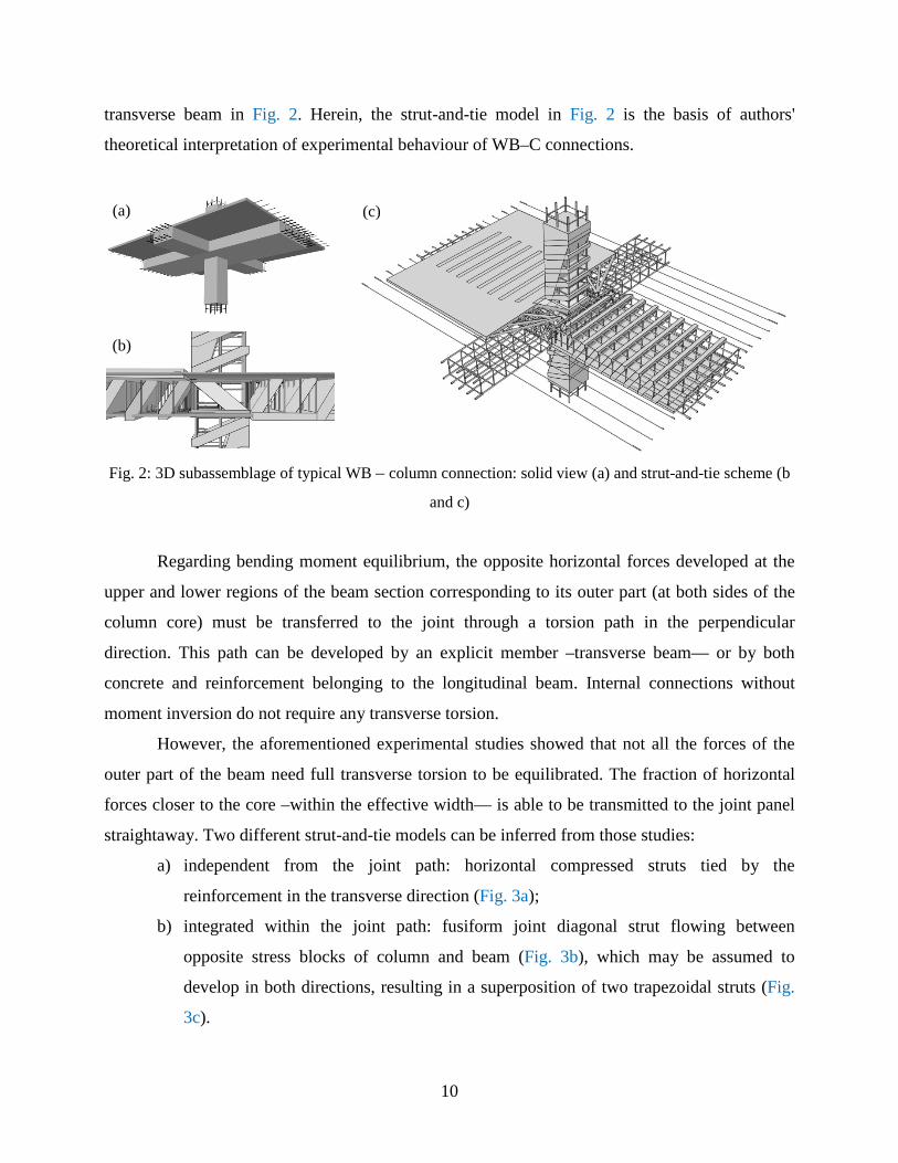
Most of these phenomena can be reproduced with different strut-and-tie mechanisms, as
shown for a typical 3D sub-assemblage of interior WB–C connection with upper slab and
10
transverse beam in Fig. 2. Herein, the strut-and-tie model in Fig. 2 is the basis of authors'
theoretical interpretation of experimental behaviour of WB–C connections.
Fig. 2: 3D subassemblage of typical WB – column connection: solid view (a) and strut-and-tie scheme (b
and c)
Regarding bending moment equilibrium, the opposite horizontal forces developed at the
upper and lower regions of the beam section corresponding to its outer part (at both sides of the
column core) must be transferred to the joint through a torsion path in the perpendicular
direction. This path can be developed by an explicit member –transverse beam— or by both
concrete and reinforcement belonging to the longitudinal beam. Internal connections without
moment inversion do not require any transverse torsion.
However, the aforementioned experimental studies showed that not all the forces of the
outer part of the beam need full transverse torsion to be equilibrated. The fraction of horizontal
forces closer to the core –within the effective width— is able to be transmitted to the joint panel
straightaway. Two different strut-and-tie models can be inferred from those studies:
a) independent from the joint path: horizontal compressed struts tied by the
reinforcement in the transverse direction (Fig. 3a);
b) integrated within the joint path: fusiform joint diagonal strut flowing between
opposite stress blocks of column and beam (Fig. 3b), which may be assumed to
develop in both directions, resulting in a superposition of two trapezoidal struts (Fig.
3c).
(a)
(b)
(c)
11
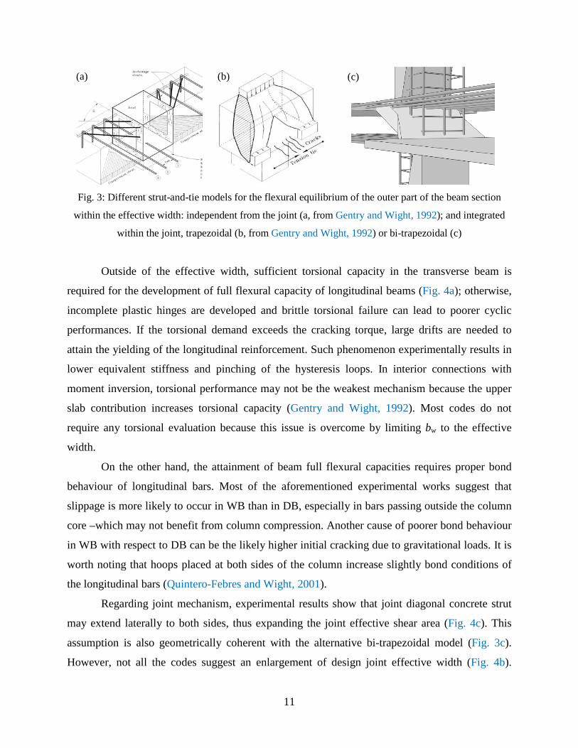
Fig. 3: Different strut-and-tie models for the flexural equilibrium of the outer part of the beam section
within the effective width: independent from the joint (a, from Gentry and Wight, 1992); and integrated
within the joint, trapezoidal (b, from Gentry and Wight, 1992) or bi-trapezoidal (c)
Outside of the effective width, sufficient torsional capacity in the transverse beam is
required for the development of full flexural capacity of longitudinal beams (Fig. 4a); otherwise,
incomplete plastic hinges are developed and brittle torsional failure can lead to poorer cyclic
performances. If the torsional demand exceeds the cracking torque, large drifts are needed to
attain the yielding of the longitudinal reinforcement. Such phenomenon experimentally results in
lower equivalent stiffness and pinching of the hysteresis loops. In interior connections with
moment inversion, torsional performance may not be the weakest mechanism because the upper
slab contribution increases torsional capacity (Gentry and Wight, 1992). Most codes do not
require any torsional evaluation because this issue is overcome by limiting bw to the effective
width.
On the other hand, the attainment of beam full flexural capacities requires proper bond
behaviour of longitudinal bars. Most of the aforementioned experimental works suggest that
slippage is more likely to occur in WB than in DB, especially in bars passing outside the column
core –which may not benefit from column compression. Another cause of poorer bond behaviour
in WB with respect to DB can be the likely higher initial cracking due to gravitational loads. It is
worth noting that hoops placed at both sides of the column increase slightly bond conditions of
the longitudinal bars (Quintero-Febres and Wight, 2001).
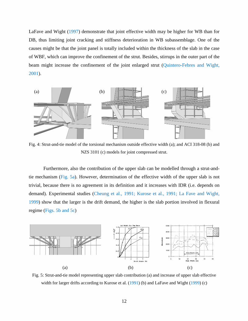
Regarding joint mechanism, experimental results show that joint diagonal concrete strut
may extend laterally to both sides, thus expanding the joint effective shear area (Fig. 4c). This
assumption is also geometrically coherent with the alternative bi-trapezoidal model (Fig. 3c).
However, not all the codes suggest an enlargement of design joint effective width (Fig. 4b).
(a) (b) (c)
12
LaFave and Wight (1997) demonstrate that joint effective width may be higher for WB than for
DB, thus limiting joint cracking and stiffness deterioration in WB subassemblage. One of the
causes might be that the joint panel is totally included within the thickness of the slab in the case
of WBF, which can improve the confinement of the strut. Besides, stirrups in the outer part of the
beam might increase the confinement of the joint enlarged strut (Quintero-Febres and Wight,
2001).
Fig. 4: Strut-and-tie model of the torsional mechanism outside effective width (a); and ACI 318-08 (b) and
NZS 3101 (c) models for joint compressed strut.
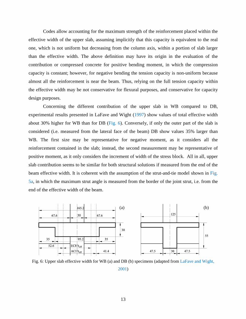
Furthermore, also the contribution of the upper slab can be modelled through a strut-and-
tie mechanism (Fig. 5a). However, determination of the effective width of the upper slab is not
trivial, because there is no agreement in its definition and it increases with IDR (i.e. depends on
demand). Experimental studies (Cheung et al., 1991; Kurose et al., 1991; La Fave and Wight,
1999) show that the larger is the drift demand, the higher is the slab portion involved in flexural
regime (Figs. 5b and 5c)
(a) (b) (c)
Fig. 5: Strut-and-tie model representing upper slab contribution (a) and increase of upper slab effective
width for larger drifts according to Kurose et al. (1991) (b) and LaFave and Wight (1999) (c)
(a) (b) (c)
13
Codes allow accounting for the maximum strength of the reinforcement placed within the
effective width of the upper slab, assuming implicitly that this capacity is equivalent to the real
one, which is not uniform but decreasing from the column axis, within a portion of slab larger
than the effective width. The above definition may have its origin in the evaluation of the
contribution or compressed concrete for positive bending moment, in which the compression
capacity is constant; however, for negative bending the tension capacity is non-uniform because
almost all the reinforcement is near the beam. Thus, relying on the full tension capacity within
the effective width may be not conservative for flexural purposes, and conservative for capacity
design purposes.
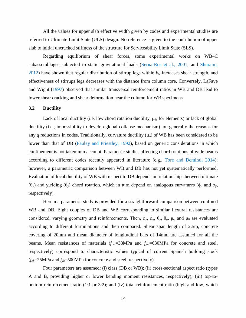
Concerning the different contribution of the upper slab in WB compared to DB,
experimental results presented in LaFave and Wight (1997) show values of total effective width
about 30% higher for WB than for DB (Fig. 6). Conversely, if only the outer part of the slab is
considered (i.e. measured from the lateral face of the beam) DB show values 35% larger than
WB. The first size may be representative for negative moment, as it considers all the
reinforcement contained in the slab; instead, the second measurement may be representative of
positive moment, as it only considers the increment of width of the stress block. All in all, upper
slab contribution seems to be similar for both structural solutions if measured from the end of the
beam effective width. It is coherent with the assumption of the strut-and-tie model shown in Fig.
5a, in which the maximum strut angle is measured from the border of the joint strut, i.e. from the
end of the effective width of the beam.
Fig. 6: Upper slab effective width for WB (a) and DB (b) specimens (adapted from LaFave and Wight,
2001)
(a) (b)
14
All the values for upper slab effective width given by codes and experimental studies are
referred to Ultimate Limit State (ULS) design. No reference is given to the contribution of upper
slab to initial uncracked stiffness of the structure for Serviceability Limit State (SLS).
Regarding equilibrium of shear forces, some experimental works on WB–C
subassemblages subjected to static gravitational loads (Serna-Ros et al., 2001; and Shuraim,
2012) have shown that regular distribution of stirrup legs within bw increases shear strength, and
effectiveness of stirrups legs decreases with the distance from column core. Conversely, LaFave
and Wight (1997) observed that similar transversal reinforcement ratios in WB and DB lead to
lower shear cracking and shear deformation near the column for WB specimens.
3.2 Ductility
Lack of local ductility (i.e. low chord rotation ductility, μθ, for elements) or lack of global
ductility (i.e., impossibility to develop global collapse mechanism) are generally the reasons for
any q reductions in codes. Traditionally, curvature ductility (μϕ) of WB has been considered to be
lower than that of DB (Paulay and Priestley, 1992), based on generic considerations in which
confinement is not taken into account. Parametric studies affecting chord rotations of wide beams
according to different codes recently appeared in literature (e.g., Tore and Demiral, 2014);
however, a parametric comparison between WB and DB has not yet systematically performed.
Evaluation of local ductility of WB with respect to DB depends on relationships between ultimate
(θu) and yielding (θy) chord rotation, which in turn depend on analogous curvatures (ϕu and ϕy,
respectively).
Herein a parametric study is provided for a straightforward comparison between confined
WB and DB. Eight couples of DB and WB corresponding to similar flexural resistances are
considered, varying geometry and reinforcements. Then, ϕy, ϕu, θy, θu, μϕ and μθ are evaluated
according to different formulations and then compared. Shear span length of 2.5m, concrete
covering of 20mm and mean diameter of longitudinal bars of 14mm are assumed for all the
beams. Mean resistances of materials (fcm=33MPa and fym=630MPa for concrete and steel,
respectively) correspond to characteristic values typical of current Spanish building stock
(fck=25MPa and fyk=500MPa for concrete and steel, respectively).
Four parameters are assumed: (i) class (DB or WB); (ii) cross-sectional aspect ratio (types
A and B, providing higher or lower bending moment resistances, respectively); (iii) top-to-
bottom reinforcement ratio (1:1 or 3:2); and (iv) total reinforcement ratio (high and low, which
15
makes top and bottom reinforcement, respectively, correspond to code’s upper and lower limit,
when top-to-bottom ratio is 3:2). Reinforcement arrangements are selected in order to obtain
similar moment resistances between analogous deep and wide beams, resulting in total
reinforcement ratios in WB approximately twice the reinforcement in DB (almost similar to the
ratio between effective depths). In each case, high reinforcement case provides approximately
three times the flexural strength provided by low reinforcement case. Common stirrup
arrangements, according to Eurocode 2 prescriptions (BSI, 2004), are considered. Characteristics
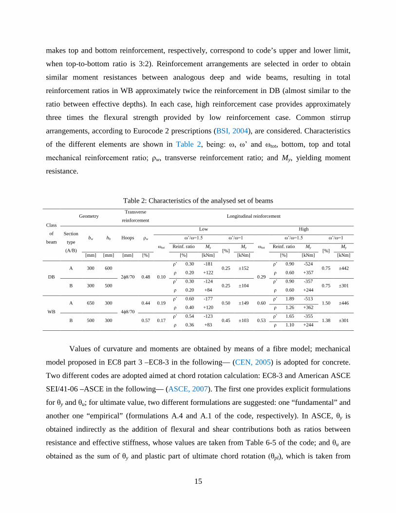
of the different elements are shown in Table 2, being: ω, ω’ and ωtot, bottom, top and total
mechanical reinforcement ratio; ρw, transverse reinforcement ratio; and My, yielding moment
resistance.
Table 2: Characteristics of the analysed set of beams
Class
of
beam
Geometry Transverse
reinforcement Longitudinal reinforcement
Section
type
(A/B)
bw hb Hoops ρw
Low High
ωtot
ω’/ω=1.5 ω’/ω=1
ωtot
ω’/ω=1.5 ω’/ω=1
Reinf. ratio My [%]
My Reinf. ratio My [%]
My
[mm] [mm] [mm] [%] [%] [kNm] [kNm] [%] [kNm] [kNm]
DB
A 300 600
2ϕ8/70 0.48 0.10
ρ’ 0.30 -181 0.25 ±152
0.29
ρ’ 0.90 -524 0.75 ±442
ρ 0.20 +122 ρ 0.60 +357
B 300 500 ρ’ 0.30 -124
0.25 ±104 ρ’ 0.90 -357
0.75 ±301 ρ 0.20 +84 ρ 0.60 +244
WB
A 650 300
4ϕ8/70
0.44 0.19 ρ’ 0.60 -177
0.50 ±149 0.60 ρ’ 1.89 -513
1.50 ±446 ρ 0.40 +120 ρ 1.26 +362
B 500 300 0.57 0.17 ρ’ 0.54 -123
0.45 ±103 0.53 ρ’ 1.65 -355
1.38 ±301 ρ 0.36 +83 ρ 1.10 +244
Values of curvature and moments are obtained by means of a fibre model; mechanical
model proposed in EC8 part 3 –EC8-3 in the following— (CEN, 2005) is adopted for concrete.
Two different codes are adopted aimed at chord rotation calculation: EC8-3 and American ASCE
SEI/41-06 –ASCE in the following— (ASCE, 2007). The first one provides explicit formulations
for θy and θu; for ultimate value, two different formulations are suggested: one “fundamental” and
another one “empirical” (formulations A.4 and A.1 of the code, respectively). In ASCE, θy is
obtained indirectly as the addition of flexural and shear contributions both as ratios between
resistance and effective stiffness, whose values are taken from Table 6-5 of the code; and θu are
obtained as the sum of θy and plastic part of ultimate chord rotation (θpl), which is taken from
16
Table 6-7 of the code. Fig. 7 shows the detailed results of the parametric study. Ratios for any
parameter A are indicated in the text as AW/D (rather than using the heavier notation AWB/ADB), and
in the bottom of graphics of Fig. 7 as W/B.
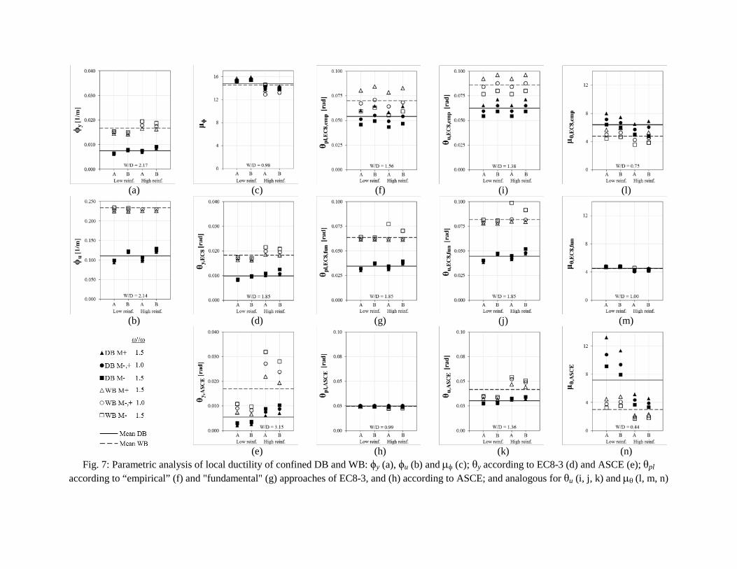
In general, when ρ’>ρ, better performances are achieved (i.e. lower yielding values and
higher ultimate ones) for both DB and WB. It is worth noting that the three adopted approaches
(EC8 and ASCE) return very different values of θ (sometimes more than 100%) in all the cases
(Fig. 7d to 7k).
Regarding curvatures, ϕy,W/D (Fig. 7a) is approximately inversely proportional to the ratio
between effective heights (dW/D), because the yielding strains at tensioned reinforcement are
similar in WB and DB, and the compression zone’s depths may be similar and small in
comparison with d, due to compressed reinforcement. Thus, ϕy,W/D≈1/dW/D. The same reasons
explain the relative values of ϕu (Fig. 7b), which are also inversely proportional to dW/D because
the confinement leads to the achievement of ultimate strains in reinforcement instead of concrete,
unlike unconfined sections, in which similar concrete “stress block” may be observed for WB and
DB (Paulay and Priestley, 1992). Hence, similar μϕ are observed for confined WB and DB (Fig.
7c) thanks to the contribution of transverse reinforcement.
EC8-3’s results of θy (Fig. 7c) reproduce the same trend than ϕy, because they are directly
proportional except for the shear experimental term in the expression, which is the less relevant.
High-reinforced sections show mean values of θy only 18% higher than low-reinforced sections,
which means that the increase of secant-to-yielding stiffness of beams may be almost
proportional to the increase of ρ. Conversely, ASCE does not consider any influence of the
reinforcement in the secant stiffness; thus, θy and My are always proportional. Stiffness
degradation (secant-to-elastic stiffness ratio) obtained with EC8 (average 0.21) is similar to the
mean value suggested in Panagiotakos and Fardis (2001) –20%— but disaggregated values for
WB (mean 0.27) are significantly higher than for DB (mean 0.16).
(a) (c) (f) (i) (l)
(b) (d) (g) (j) (m)
(e) (h) (k) (n)
Fig. 7: Parametric analysis of local ductility of confined DB and WB: ϕy (a), ϕu (b) and µφ (c); θy according to EC8-3 (d) and ASCE (e); θpl according to “empirical” (f) and "fundamental" (g) approaches of EC8-3, and (h) according to ASCE; and analogous for θu (i, j, k) and µθ (l, m, n)
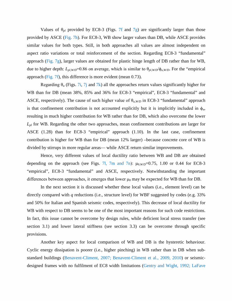
Values of θpl provided by EC8-3 (Figs. 7f and 7g) are significantly larger than those
provided by ASCE (Fig. 7h). For EC8-3, WB show larger values than DB, while ASCE provides
similar values for both types. Still, in both approaches all values are almost independent on
aspect ratio variations or total reinforcement of the section. Regarding EC8-3 “fundamental”
approach (Fig. 7g), larger values are obtained for plastic hinge length of DB rather than for WB,
due to higher depth: Lpl,W/D=0.86 on average, which is similar to θpl,W/D/ϕu,W/D. For the “empirical
approach (Fig. 7f), this difference is more evident (mean 0.73).
Regarding θu (Figs. 7i, 7j and 7k) all the approaches return values significantly higher for
WB than for DB (mean 38%, 85% and 36% for EC8-3 “empirical”, EC8-3 “fundamental” and
ASCE, respectively). The cause of such higher value of θu,W/D in EC8-3 “fundamental” approach
is that confinement contribution is not accounted explicitly but it is implicitly included in ϕu,
resulting in much higher contribution for WB rather than for DB, which also overcome the lower
Lpl for WB. Regarding the other two approaches, mean confinement contributions are larger for
ASCE (1.28) than for EC8-3 “empirical” approach (1.10). In the last case, confinement
contribution is higher for WB than for DB (mean 12% larger) –because concrete core of WB is
divided by stirrups in more regular areas— while ASCE return similar improvements.
Hence, very different values of local ductility ratio between WB and DB are obtained
depending on the approach (see Figs. 7l, 7m and 7n): μθ,W/D=0.75, 1.00 or 0.44 for EC8-3
“empirical”, EC8-3 “fundamental” and ASCE, respectively. Notwithstanding the important
differences between approaches, it emerges that lower μθ may be expected for WB than for DB.
In the next section it is discussed whether these local values (i.e., element level) can be
directly compared with q reductions (i.e., structure level) for WBF suggested by codes (e.g. 33%
and 50% for Italian and Spanish seismic codes, respectively). This decrease of local ductility for
WB with respect to DB seems to be one of the most important reasons for such code restrictions.
In fact, this issue cannot be overcome by design rules, while deficient local stress transfer (see
section 3.1) and lower lateral stiffness (see section 3.3) can be overcome through specific
provisions.
Another key aspect for local comparison of WB and DB is the hysteretic behaviour.
Cyclic energy dissipation is poorer (i.e., higher pinching) in WB rather than in DB when sub-
standard buildings (Benavent-Climent, 2007; Benavent-Climent et al., 2009, 2010) or seismic-
designed frames with no fulfilment of EC8 width limitations (Gentry and Wight, 1992; LaFave
19
and Wight, 1997; Quintero-Febres and Wight, 1997) are considered. Even in the case of EC8-
conforming WB–C connections, pinching is still significant (Quintero-Febres and Wight, 1997;
and Li and Kulkarni, 2010). LaFave and Wight (1997) quantify such hysteretical behaviour in
terms of observed equivalent viscous damping, which is 20% lower for WB subassemblages than
in DB. The causes may be the poorer bond behaviour and the poorer transverse beam torsional
performances of WB specimens.
On the other hand, global ductility of frames (i.e. top displacement capacity of frames)
depends not only on local ductility of members but also on the ability to develop global
mechanisms, which requires capacity design of columns. Experimental results on sub-standard
WBF (Benavent-Climent et al., 2010) show beam-sway mechanisms even without capacity
design of columns, because torsional failure of transverse beams prevent the attainment of full
flexural capacities in longitudinal beams so columns get “protected”. However, this is not an
advantage in terms of frame top displacement capacity since torsional failure is not ductile.
3.3 Lateral stiffness
Usually, WB have substantial lower member stiffness –both elastic and secant to
yielding— than DB, leading to lower global stiffness of corresponding frames for similar global
geometry and similar dimensions of column sections. Notwithstanding the consequent lower
demands, severe disadvantages occur: (i) higher non-structural damage, and (ii) higher relevance
of second order effects (P-Δ) on columns. Lateral stiffness issue represents one of the main
reasons why codes have historically limited WBF expected performances. However, as long as
codes provide IDR limitations and simplified consideration of P-Δ effects, lateral stiffness is not
an issue anymore as WBF must compensate the lower stiffness of beams with higher column
dimensions. Only in the case of codes with no IDR limitation (such as NCSE-02) it may be
reasonable to provide indirectly higher lateral stiffness to the frame through the use of very low q,
consequently increasing strength demand and likely dimensions of elements.
As design to DLS is displacement-based, codes compel to consider kind of stiffness
degradation in members up to yielding, aimed at conservativeness. However, codes suggest
different reduction factors with respect to gross stiffness. EC8 suggests a reduction of 50%;
American ASCE/SEI 41-06 suggests reductions up to a 70% for beams and 30-70% for columns;
Italian NTC from 0% to 50%; New Zealander NZS 3101, 60-73% and 0-70% for ULS beams and
columns, respectively, and 0-65% for DLS.
20
On the other hand, the concerns for WBF lateral stiffness seem to be the result of the
identification of WBF with flat-slab frames, which suffer strong cyclic degradation of shear
capacity with the increasing ductility demand, with consequent brittle punching shear failures
often observed (Pan and Moehle, 1989; and Hawkins and Michell, 1979). However, this kind of
failures has no counterpart in WB sub-assemblages with code-compliant width limitations.
Furthermore, code provisions regarding the predominant component of the deformed shape (i.e.
shear- or cantilever-type) seems to be without any mechanical basis.
Previous considerations are consistent with the assumption that frame stiffness only
depends on flexural stiffness of members, from an analytical point of view. However,
experimental studies (LaFave and Wight, 2001) show that effective stiffness of WBF can be
much higher than expected. The latter may be the result of (i) less cracking and deformability of
the joint; (ii) higher slab participation; (iii) less shear cracking in plastic hinges; and (iv) likely
higher reinforcement ratios.
4. SIMPLIFIED SPECTRAL ESTIMATION OF RELATIVE PERFORMANCES
BETWEEN DEEP- AND WIDE-BEAM FRAMES
The spectral approach provided herein is a simplified assessment of global seismic
performances of WBF with respect to DBF, finally aimed at a contextualization of code
provisions regarding q reduction reviewed in section 2 and experimental and analytical
observations provided in section 3.
In section 3 it is concluded that the lower µθ of WB respect to DB is the likely reason of q
reduction for WBF proposed by some codes (see Table 1 and Table 3). However, q is a global
structural quantity and it cannot be straightforward related to µθ, which is a proxy of single
element performances. In fact, q not only depends on global ductility (Rμ) but also on other two
factors: overstrength (RS), and demand reduction (RD), i.e, the ratio between strength demands
corresponding to design and effective periods (Borzi and Elnashai, 2000; Mwafy and Elnashai,
2002). Furthermore, Rμ not only depends on local ductility of beams (µθ,b) but also on that of
columns.
All the following conditions should be satisfied in order to get a direct translation of
µθ,W/D of beams in the ratio between behaviour factors of WBF and DBF (qW/D):
1) DBF and WBF show similar overstrength until first structural yielding and similar RD;
21
2) DBF and WBF show similar collapse of mechanisms, evaluated through the height of
frame effectively involved in it (Hmec);
3) negligible difference on first yielding displacement if observed on the capacity curve or
on its piecewise linear fit;
4) the first member end yielding is a beam;
5) the first member end which reaches θu is the same beam of point 4);
6) from the attainment of first yielding all member ends (yielded or not) rotate at the same
rate.
The first condition may be likely satisfied if similar strategies of design are employed.
The second one depends on the column-to-beam capacity design ratio, and it, in turn, depends on
section design overstrengths, which can be very different (see section 4.2). The third condition
can be neglected as it is an implicit source of uncertainties even if the same fitting rule is
employed for the two structures (De Luca et al., 2013). Condition 4 is plausible because of
capacity design of columns. However, condition 5 and 6 can seldom be achieved. The first
element reaching θu can be a column (which is the most usual situation, see section 4.2); and even
if it is a beam instead, it is quite likely that a different beam reaches θu. In fact, redistribution of
bending moments between members cannot be really predicted a priori, and it causes non-
proportional evolution of chord rotations. Hence, µθ,b≠Rμ≠q, thus global performances of WBF
are not necessarily poorer than DBF because of lower local ductility of beams.
4.1 Safety Factor ratio
Aimed at comparing the relative capacities of WBF and DBF, it is convenient to assess
the problem in the acceleration-displacement response spectrum (ADRS) format, shifting from q
to PGA (Peak Ground Acceleration corresponding to the site soil) safety factor. This is only
possible if spectra for different PGA are homothetic (as in EC8).
Global performance of a building could be represented by its safety factor
SF=PGAc/PGAd, i.e. the ratio between capacity (PGAc) and demand (PGAd) in terms of PGA.
Since PGAd is equal for WBF and DBF structures at the same site, the comparison of global
performances can be done in terms of PGA capacity ratio of WBF and DBF (PGAc,W/D). The
estimation of PGAc through spectral procedures asks for the assumption of a strength reduction
factor – ductility – period (Rμ-µ-T) relationship (e.g., Vidic et al. 1994; Miranda and Bertero,
1994; Vamvatsikos and Cornell, 2006), that is also the basis of behaviour factor definition. Then,
22
SF only depends on two variables: effective period (Teff) and maximum displacement capacity
(Sdc) of the equivalent single degree of freedom (SDOF), assuming that the response is controlled
by a single mode. Equal-displacement rule, i.e. Teff>TC (being TC the period corresponding to the
end of the constant-acceleration branch of the spectrum) can be assumed in all the cases. Thus,
the safety factor of buildings can be expressed as the ratio of spectral displacement capacity and
demand: SF=Sdc/Sdd.
Teff>TC is a robust assumption for buildings of at least 2 storeys designed according to
EC8 spectra (types 1 and 2, for any soil type), see Gómez-Martínez (2015). It is based on the
design elastic period suggested by EC8 as lower bound value for “modern” capacity-designed
and DLS-designed frames (Crowley and Pinho, 2010), and on mean member stiffness
degradation ratio from elastic to effective (0.20) proposed by Panagiotakos and Fardis (2001) as
representative of the whole frame behaviour.
Spectral displacement capacity of the SDOF is obtained from top displacement capacity
of the frame (Du) as in Eq. 1, being Γ the first mode participation factor, and θu,min the minimum
ultimate chord rotation among those at (i) column bases, (ii) column tops at a height of Hmec (both
θuc), and (iii) beam ends under Hmec (θub) (Fardis, 2009).
,minmec uudc
HDS⋅θ
= ≈Γ Γ
(1)
As shown in Fig. 8, a “rigid” mechanism of n storeys is assumed, without any pre-
yielding contribution neither of the (n-1) upper storeys nor of the intermediate column ends, and
assuming similar evolution of chord rotations in all the member ends involved. The above
assumptions are at the basis of other spectral approaches (Mazzolani and Piluso, 1997; Calvi,
1999; Decanini and Mollaioli, 2000; Cosenza et al., 2005; Iervolino et al, 2007; Borzi et al.,
2008).
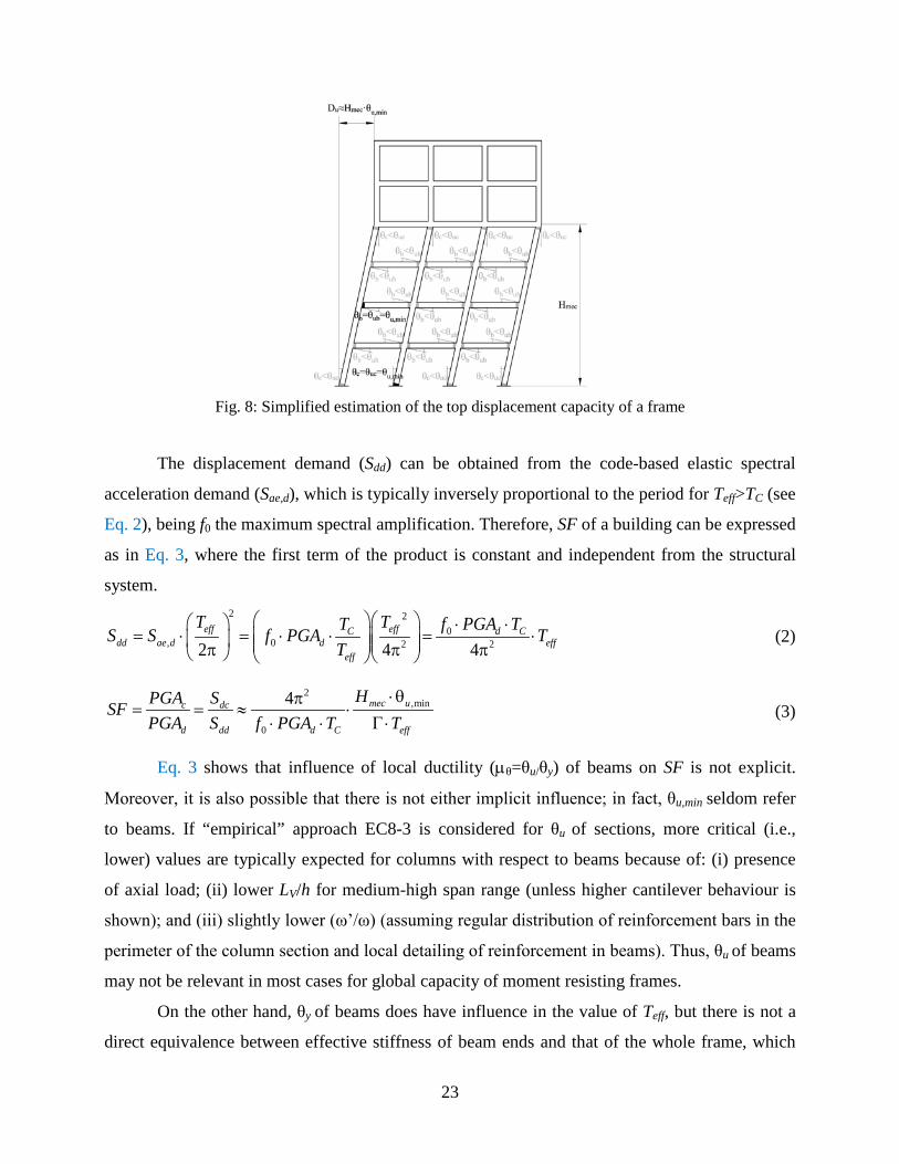
23
Fig. 8: Simplified estimation of the top displacement capacity of a frame
The displacement demand (Sdd) can be obtained from the code-based elastic spectral
acceleration demand (Sae,d), which is typically inversely proportional to the period for Teff>TC (see
Eq. 2), being f0 the maximum spectral amplification. Therefore, SF of a building can be expressed
as in Eq. 3, where the first term of the product is constant and independent from the structural
system. 2 2
0, 0 2 22 4 4
⋅ ⋅= ⋅ = ⋅ ⋅ = ⋅ π π π
eff effC d Cdd ae d d eff
eff
T TT f PGA TS S f PGA TT
(2)
2,min
0
4 mec uc dc
d dd d C eff
HPGA SSFPGA S f PGA T T
⋅θπ= = ≈ ⋅
⋅ ⋅ Γ ⋅ (3)
Eq. 3 shows that influence of local ductility (µθ=θu/θy) of beams on SF is not explicit.
Moreover, it is also possible that there is not either implicit influence; in fact, θu,min seldom refer
to beams. If “empirical” approach EC8-3 is considered for θu of sections, more critical (i.e.,
lower) values are typically expected for columns with respect to beams because of: (i) presence
of axial load; (ii) lower LV/h for medium-high span range (unless higher cantilever behaviour is
shown); and (iii) slightly lower (ω’/ω) (assuming regular distribution of reinforcement bars in the
perimeter of the column section and local detailing of reinforcement in beams). Thus, θu of beams
may not be relevant in most cases for global capacity of moment resisting frames.
On the other hand, θy of beams does have influence in the value of Teff, but there is not a
direct equivalence between effective stiffness of beam ends and that of the whole frame, which
24
also depend on columns. Moreover, when DLS rules the design process, again θy of beams would
not have any influence on Teff as lateral stiffness of the frame becomes a target and section of
columns are designed accordingly. Thus, local ductility of columns may be more relevant on the
global ductility than that of beams.
4.2 Estimation of relative performances between WBF and DBF
In this section, a rough prediction of the relative global capacities between WBF and DBF
in most practical cases is carried out. All the simplifications are assumed in order to be
conservative from the point of view of WBF, i.e. unfavourable for WBF with respect to DBF.
The legitimacy of such simplified estimation is limited, because not only the assessment
procedure but also the parameters derived from design are assumed “a priori”.
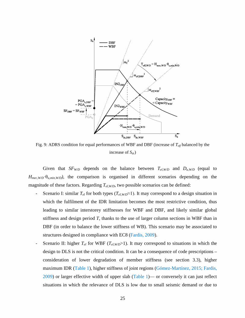
Relative SF between WBF and DBF (SFW/D, see Eq. 4) when designed to the same PGAd
is developed from Eq. 3. Fig. 9 provides a graphical example, in the ADRS format, of condition
leading to same performances for WBF and DBF: the increase of Teff is balanced by a similar
increase of displacement capacity. Fig. 9 shows bilinear capacity curves, corresponding IN2
curves (Dolšek and Fajfar, 2004), common demand spectrum, and scaled capacity spectrum with
their corresponding values of PGAc both for WBF and DBF.
, / ,min, //
/ , /
mec W D u W DW D
W D eff W D
HSF
T⋅θ
=Γ ⋅
(4)
Both structures are assumed to be designed adopting similar q, similar corrections due to
second-order effects, similar ρtot between corresponding columns of both types, and similar
(ω’/ω) between corresponding beams. Also Γ may be similar for WBF and DBF, according to
several codes (e.g., ASCE/SEI 41-06).
Regarding Teff, WBF may show lower period elongation (Teff/Tel) than DBF, if the
experimental behaviour shown in LaFave and Wight (2001) for single connections (see section
3.3) is extrapolated to the whole frame. Thus, Teff,W/B can be estimated (Eq. 5) as the ratio between
elastic periods (Tel,W/D) weighted by a factor fK,sec, which is included in Eq. 5 after being switched
from stiffness-based to period-based. However, the experimental-based value fK,sec≈1.48 (LaFave
and Wight, 2001) is considered just as an upper-bound level. So, aimed at conservativeness, all
the following simplified development are carried out assuming fK,sec=1. 0.5
, / , / ,seceff W D el W D KT T f −= ⋅ (5)
25
Fig. 9: ADRS condition for equal performances of WBF and DBF (increase of Teff balanced by the
increase of Sdc)
Given that SFW/D depends on the balance between Tel,W/D and Du,W/D (equal to
Hmec,W/D·θu,min,W/D), the comparison is organised in different scenarios depending on the
magnitude of these factors. Regarding Tel,W/D, two possible scenarios can be defined:
- Scenario I: similar Tel for both types (Tel,W/D≈1). It may correspond to a design situation in
which the fulfilment of the IDR limitation becomes the most restrictive condition, thus
leading to similar interstorey stiffnesses for WBF and DBF, and likely similar global
stiffness and design period T, thanks to the use of larger column sections in WBF than in
DBF (in order to balance the lower stiffness of WB). This scenario may be associated to
structures designed in compliance with EC8 (Fardis, 2009).
- Scenario II: higher Tel for WBF (Tel,W/D>1). It may correspond to situations in which the
design to DLS is not the critical condition. It can be a consequence of code prescriptions –
consideration of lower degradation of member stiffness (see section 3.3), higher
maximum IDR (Table 1), higher stiffness of joint regions (Gómez-Martínez, 2015; Fardis,
2009) or larger effective width of upper slab (Table 1)— or conversely it can just reflect
situations in which the relevance of DLS is low due to small seismic demand or due to
26
higher relative importance of gravity loads –e.g. very high number of storeys (Gómez-
Martínez et al., 2015c)—, regardless of the code adopted for design.
In general, the higher is the member overstrength ratio between columns and beams in a
frame, the higher is Hmec. Considering that minimum ρtot is required for columns, in general larger
column sections causes higher overstrength. For both scenarios, columns of upper storeys may
present larger sections for WBF rather than DBF because of beam effective width limitation in
WB (see Table 1), especially when large bw are required for WB (i.e. high seismic demand or
deflection limitation due to gravitational loads in large-span beams). Furthermore, for scenario I,
larger column sections in the whole building are required for WBF rather than for DBF in order
to provide similar stiffness (see section 3.3). Hence, Hmec,W/D>1.0 for scenario I and Hmec,W/D≥1.0
for scenario II.
Regarding θu,min,W/D, in each structural type the critical member can be a beam or a
column. Therefore, four sub-scenarios of relative performances could be configured. WB show
greater values of θu than DB (1.38 times could be a representative value according to section 3.2).
In columns, local ductility increase with the section dimensions: substantial increase of secant
stiffness is shown, while values of θu may not vary substantially (assuming fixed LV and axial
loads, see Gómez-Martínez, 2015). Hence, θuc,min,W/D may be only proportional to LV0.35. As
cantilever behaviour may be higher for WBF than DBF, LV,W/D≥1.0 and thus θuc,min,W/D≥1.0.
Hence, for WBF the probability for columns to be the first element to exhaust its rotation
capacity may be higher than for DBF. The above consideration finds solid confirmation in other
literature studies (e.g., Gómez-Martínez, 2015). The probability of occurrence of each situation
depends of the ratio between LV of columns and beams: large-span buildings may show poorer
performance for WBF than medium/short-span ones.
Nevertheless, it is not clear how smaller SFW/D should be in order to justify a reduction of
q for WBF. In fact, the implicit safety factor in q-based design is very high: quite large dispersion
of results for SF can be observed between very similar structures, considering the very simplified
nature of the q-based design and the non-negligible influence of personal choices of design
(Mwafy and Elnashai, 2002).
Despite the limited scope of the simplified approach presented in this section, some
relevant points can be remarked:
27
- local ductility of beams may not be the most relevant parameter governing the relative
performance of WBF and DBF;
- instead, global stiffness of the frame and overstrength of columns may rule SFW/D, thus
the more restrictive is the code regarding design to DLS, the more favourable is WBF
performance respect to DBF one.
5. CONCLUSIONS
The reason why some Mediterranean codes do not consider reinforced concrete wide
beam moment resisting frames (WBF) as high ductility systems is investigated. National codes of
Spain, Italy, Greece and Turkey are compared with benchmark codes of Europe, USA, and New
Zealand. Based on the traditional identification of flat-slab frames with WBF, also code
limitations on flat slabs are examined in order to understand the analogy with some specific
provisions on wide-beam frames. Experimental studies on wide beams are then reviewed, and
strut-and-tie micro-models for connections are discussed.
From review of codes and experimental studies, it emerged that the only basis on which
some codes, such as the Italian and the Spanish ones, prescribe a significant reduction of the
behaviour factor for WBF (i.e., 33% and 50% respectively) is the poorer local ductility of wide
beams respect to deep beams. Modern code provisions overcome other potential shortcomings of
WBF, as stress transfer in connections or their higher deformability.
Thus, the capable local and global ductility of wide-beam frames (WBF) is investigated
with respect to deep beam frames (DBF). Analytical results and a systematic comparison between
wide and deep beams are provided. First, a detailed parametric analysis of local ductility of
beams is carried out. Then, a spectral-based simplified approach is proposed for the comparison
of global capacity of wide and deep beam frames.
Results show that the set of prescriptions given by each modern seismic code provides
sufficient ductility to WBF designed in DCH. In fact, global ductility of WBF relies more on the
lateral stiffness of the frames and on the overstrength of columns rather than on the local ductility
of wide beams, systematically lower with respect to that of deep beams. Thus, the more a code
provides restrictive provisions on damage limitation, the more any performance gap between
WBF and DBF can be neglected. If damage limitation becomes the critical condition of design,
28
likely similar stiffnesses are expected for both frames, while displacement capacities may be
larger for WBF due to larger column overstrengths.
Hence, based on the analytical results and on the simplified spectral considerations
provided, it could be stated that wide-beam frames can be designed as high ductility systems, and
no reduction of q is necessary for their design for codes in which damage limitation is likely to be
the critical condition and specific provision for satisfactory performances of wide beam-column
connections are provided.
REFERENCES ACI (1989). Building Code Requirements for Reinforced Concrete (ACI 318-89). ACI Committee 318,
American Concrete Institute, Farmington Hills, Michigan, USA.
ACI (2008). Building Code Requirements for Structural Concrete (ACI 318-08) and Commentary (318-08). ACI Committee 318, American Concrete Institute, Farmington Hills, Michigan, USA
ACI-ASCE (1991). Recommendations for Design of Beam-Column Connections in Monolithic Reinforced Concrete Structures (ACI 352R-91). Joint ACI-ASCE Committee 352, American Concrete Institute, Farmington Hills, Michigan, USA.
ACI-ASCE (2002). Recommendations for Design of Beam-Column Connections in Monolithic Reinforced Concrete Structures (ACI 352R-02). Joint ACI-ASCE Committee 352, American Concrete Institute, Farmington Hills, Michigan, USA.
Arslan, M. H., Korkmaz, H. H. (2007). What is to be learned from damage and failure of reinforced concrete structures during recent earthquakes in Turkey? Engineering Failure Analysis, 14(1), 1-22.
ASCE (2007). Seismic Rehabilitation of Existing Buildings, ASCE/SEI 41-06. American Society of Civil Engineers, Reston, Virginia, USA
ASCE (2010). Minimum Design Loads for Building and Other Structures, ASCE/SEI 7-10. American Society of Civil Engineers, Reston, Virginia, USA.
Benavent-Climent, A. (2007). Seismic behavior of RC side beam-column connections under dynamic loading. Journal of Earthquake Engineering 11:493-511.
Benavent-Climent, A., Cahís, X., Zahran, R. (2009). Exterior wide beam-column connections in existing RC frames subjected to lateral earthquake loads. Engineering Structures 31:1414-1424.
Benavent-Climent, A., Cahís, X., Vico, J.M. (2010). Interior wide beam-column connections in existing RC frames subjected to lateral earthquake loading. Bulletin of Earthquake Engineering 8:401-420.
Benavent-Climent, A., Zahran, R. (2010). An energy-based procedure for the assessment of seismic capacity of existing frames: application to RC wide beam systems in Spain. Soil Dynamics and Earthquake Engineering 30:354-367
BHRC (2004). Iranian Code of Practice for Seismic Resistant Design of Buildings. Standard Nº 2800, 3rd edn. Building and Housing Research Center, Tehran, Iran.
BSI (2004). Eurocode 2: Design of concrete structures: Part 1-1: General rules and rules for buildings. British Standards Institutions, London, UK.
29
Borzi, B., Elnashai, A.S. (2000). Refined force reduction factors for seismic design. Engineering Structures 22:1244-1260.
Borzi, B., Pinho, R., Crowley, H. (2008). Simplified pushover-based vulnerability analysis for large-scale assessment of RC buildings. Engineering Structures 30:804-820.
Calvi, G.M. (1999). A displacement-based approach for vulnerability evaluation of classes of buildings. Journal of Earthquake Engineering 3(3):411-438.
CEN (2004). Eurocode 8: design of structures for earthquake resistance – Part 1: general rules, seismic actions and rules for buildings. European Standard EN 1998-1:2003 – Comité Européen de Normalisation, Brussels, Belgium.
CEN (2005). Eurocode 8: design of structures for earthquake resistance – Part 3: assessment and retrofitting of buildings. European Standard EN 1998-1:2005 – Comité Européen de Normalisation, Brussels, Belgium.
CDSC (1994). Seismic construction code, NCSR-94. Committee for the Development of Seismic Codes, Spanish Ministry of Construction, Madrid, Spain (in Spanish).
CDSC (2002). Seismic construction code, NCSE-02. Committee for the Development of Seismic Codes, Spanish Ministry of Construction, Madrid, Spain (in Spanish).
Cheung, P.C., Paulay, T., Park, R. (1991). Mechanisms of slab contributions in beam-column subassemblages. ACI special publication(123).
Cosenza, E., Manfredi, G., Polese, M., Verderame, G.M. (2005). A multilevel approach to the capacity assessment of existing RC buildings. Journal of Earthquake Engineering 9(1):1-22.
Crowley, H., Pinho, R. (2010). Revisiting Eurocode 8 formulae for periods of vibration and their employment in linear seismic analysis. Earthquake Engineering and Structural Dynamics 39:223-235.
CS.LL.PP (2009). Instructions for the application of the Technique Code for the Constructions. Official Gazette of the Italian Republic, 47 (in Italian).
Decanini, L.D., Mollaioli, F. (2000). Analisi di vulnerabilità sismica di edifici in cemento armato pre-normativa – Comportamento sismico di edifici in cemento armato progettati per carichi verticali. E. Cosenza ed., CNR – Gruppo Nazionale per la Difesa dei Terremoti, Rome, Italy (in Italian).
De Luca F., Vamvatsikos D., Iervolino I. (2013) Near-optimal piecewise linear fits of static pushover capacity curves for equivalent SDOF analysis, Earthquake Engineering and Structural Dynamics, 42(4): 523-543.
De Luca, F., Verderame, G.M., Gómez-Martínez, F., Pérez-García, A. (2014). The structural role played by masonry infills on RC building performances after the 2011 Lorca, Spain, earthquake. Bulletin of Earthquake Engineering 12(5):1999-2026.
Domínguez, D., López-Almansa, F., Benavent-Climent, A. (2014). Comportamiento para el terremoto de Lorca de 11-05-2011, de edificios de vigas planas proyectados sin tener en cuenta la acción sísmica. Informes de la Construcción 66(533):e008 (in Spanish).
Domínguez, D., López-Almansa, F., Benavent-Climent, A. (2016). Would RC wide-beam buildings in Spain have survived Lorca earthquake (11-05-2011)? Engineering Structures 108:134-154
Dönmez, C. (2013). Seismic Performance of Wide-Beam Infill-Joist Block RC Frames in Turkey. Journal of Performance of Constructed Facilities, 29(1), 04014026.
Dolšek, M., Fajfar, P. (2004). IN2 – A simple alternative for IDA. Proceedings of the 13th World conference on Earthquake Engineering. August 1-6, Vancouver, Canada. Paper 3353.
30
Fadwa, I., Ali, T.A., Nazih, E., Sara, M. (2014). Reinforced concrete wide and conventional beam-column connections subjected to lateral load. Engineering Structures 76:34-48
Fardis, M.N. (2009). Seismic Design, Assessment and Retrofitting of Concrete Buildings. Ed. Springer, London, UK.
Gentry, T.R., Wight, J.K. (1992). Reinforced concrete wide beam-column connections under earthquake-type loading. Report nº UMCEE 92-12. Department of Civil and Environmental Engineering, University of Michigan, Ann Arbor, Michigan, USA.
Gómez-Martínez, F. (2015). FAST simplified vulnerability approach for seismic assessment of infilled RC MRF buildings and its application to the 2011 Lorca (Spain) earthquake. PhD Thesis, Polytechnic University of Valencia, Spain.
Gómez Martínez, F., Pérez García, A., De Luca, F., Verderame, G.M. (2015a). Comportamiento de los edificios de HA con tabiquería durante el sismo de Lorca de 2011: aplicación del método FAST. Informes de la Construcción 67(537):e065 (in Spanish).
Gómez-Martínez, F., Pérez-García, A., Alonso Durá, A., Martínez Boquera, A., Verderame, G.M. (2015b). Eficacia de la norma NCSE-02 a la luz de los daños e intervenciones tras el sismo de Lorca de 2011. Proceedings of Congreso Internacional sobre Intervención en Obras Arquitectónicas tras Sismo: L’Aquila (2009), Lorca (2011) y Emilia Romagna (2012), may 13-14, Murcia, Spain (in Spanish).
Gómez-Martínez, F., Verderame, G.M., De Luca, F., Pérez-García, A., Alonso-Durá, A. (2015c). High ductility seismic performances of wide-beam RC frames. XVI Convegno ANIDIS. September 13-17, L’aquila, Italy.
Hawkins, N.M., Mitchell, D. (1979). Progressive collapse of flat plate structures. ACI Journal(7):775-808.
Iervolino, I., Manfredi, G., Polese, M., Verderame, G.M., Fabbrocino, G. (2007). Seismic risk of RC building classes. Engineering Structures 29(5):813-820.
Inel, M., Ozmen, H. B., Akyol, E. (2013). Observations on the building damages after 19 May 2011 Simav (Turkey) earthquake. Bulletin of Earthquake Engineering, 11(1), 255-283.
Kurose, Y., Guimaraes, G.N., Zuhua, L., Kreger, M.E., Jirsa, J.O. (1991). Evaluation of slab-beam-column connections subjected to bidirectional loading. ACI special publication(123).
LaFave, J.M., Wight, J.K. (1997). Behavior of reinforced exterior wide beam-column-slab connections subjected to lateral earthquake loading. Report nº UMCEE 97-01. Department of Civil and Environmental Engineering, University of Michigan, Ann Arbor, Michigan, USA.
LaFave, J.M., Wight, J.K. (1999). Reinforced concrete exterior wide beam-column-slab connections subjected to lateral earthquake loading. ACI Structural Journal 96(4):577-586.
LaFave, J.M., Wight, J.K. (2001). Reinforced concrete wide-beam construction vs. conventional construction: resistance to lateral earthquake loads. Earthquake Spectra 17(3):479-505.
López-Almansa, F., Domínguez, D., Benavent-Climent, A. (2013). Vulnerability analysis of RC buildings with wide beams located in moderate seismicity regions. Engineering Structures 46:687-702.
Li, B., Kulkarni, S.A. (2010). Seismic behavior of reinforced concrete exterior wide beam-column joints. Journal or Structural Engineering (ASCE) 136(1):26-36.
Masi, A., Santarsiero, G., Nigro, D. (2013a). Cyclic tests on external RC beam-column joints: role of seismic design level and axial load value on the ultimate capacity. Journal of Earthquake Engineering 17(1):110-136.
31
Masi, A., Santarsiero, G., Mossucca, A., Nigro, D. (2013b). Seismic behaviour of RC beam-column subassemblages with flat beam. Proceedings of XV Convegno della Associazione Nazionale Italiana di Ingegneria Sismica, ANIDIS. Padova, Italy.
Mazzolani, F.M., Piluso, V. (1997). Plastic design of seismic resistant steel frames. Earthquake Engineering and Structural Dynamics 26:167-191.
MEPP (2000a). Greek Earthquake Resistant Design Code, EAK 2000. Ministry of Environment, Planning and Public Works, Athens, Greece.
MEPP (2000b). Greek Code for the Design and Construction of Concrete Works, EKOS 2000. Ministry of Environment, Planning and Public Works, Athens, Greece (in Greek).
Miranda, E., Bertero, V.V. (1994). Evaluation of strength reduction factors for earthquake-resistant design. Earthquake Spectra 10(2):357-379.
MPWS (2007). Specifications for buildings to be built in seismic areas. Turkish Standards Institution, Ministry of Public Works and Settlement, Ankara, Turkey (in Turkish).
Mwafy, A.M., Elnashai, A.S. (2002). Calibration of force reduction factors of RC buildings. Journal of Earthquake Engineering 6(2):239-273.
NZS (2004). Structural Design Actions. Part 5: Earthquake actions, NZS 1170.5. New Zealand Standards, Wellington, New Zealand.
NZS (2006). Concrete Structures Standard: Part 1 – The Design of Concrete Structures, NZS 3101 part 1. New Zealand Standards, Wellington, New Zealand.
Pan, A., Moehle, J.P. (1989). Lateral displacement ductility of reinforced concrete flat plates. ACI Structural Journal 86(3):250-258.
Panagiotakos, T.B., Fardis, M.N. (2001). Deformations of reinforced concrete members at yielding and ultimate. ACI Structural Journal 98(2):135-148 and Appendix 1 (69 pp.).
Paulay, T., Priestley, M.J.N. (1992). Seismic design of concrete and masonry structures. John Wiley and Sons, New York, USA.
Quintero-Febres, C.G., Wight, J.K. (1997). Investigation on the seismic behavior of RC interior wide beam-column connections. Report nº UMCEE 97-15. Department of Civil and Environmental Engineering, University of Michigan, Ann Arbor, Michigan, USA.
Quintero-Febres, C.G., Wight, J.K. (2001). Experimental study of Reinforced concrete interior wide beam-column connections subjected to lateral loading. ACI Structural Journal 98(4):572-582.
Serna-Ros, P., Fernández-Prada, M.A., Miguel-Sosa, P., Debb, O.A.R. (2001). Influence of stirrup distribution and support width on the shear strength of reinforced concrete wide beams. Magazine of Concrete Research 54(00):1-11.
Siah, W.L., Stehle, J.S., Mendis, P., Goldsworthy, H. (2003). Interior wide beam connections subjected to lateral earthquake loading. Engineering Structures 25:281-291.
Shuraim, A.B. (2012). Transverse stirrup configurations in RC wide shallow beams supported on narrow columns. Journal of Structural Engineering 138(3):416-424.
Tore, E., Demiral, T. (2014). A parametric study of code-based performance limits for wide beams. e-GFOS, 5(8), 1-11.
Vamvatsikos, D., Cornell, C.A. (2002). Incremental Dynamic Analysis. Earthquake Engineering and Structural Dynamics, 31:491-514.
32
Vidic, T., Fajfar, P., Fischinger, M. (1994). Consistent inelastic design spectra: strength and displacement. Earthquake Engineering and Structural Dynamics 23:507-521.
Vielma, J.C., Barbat, A.H., Oller, S. (2010). Seismic safety of low ductility structures used in Spain. Bulletin of Earthquake Engineering 8:135-155.