© Copyright 2019 Wenqing Ju
46
© Copyright 2019 Wenqing Ju
Transcript of © Copyright 2019 Wenqing Ju

© Copyright 2019
Wenqing Ju

Multiplexed Carbon Nanotube Sensing film for Smart Soil Application
Wenqing Ju
A thesis
submitted in partial fulfillment of the
requirements for the degree of
Master of Science in Mechanical Engineering
University of Washington
2019
Committee:
Jae-hyun Chung, Chair
Igor Novosselov
Sawyer Fuller
Program Authorized to Offer Degree:
Mechanical Engineering

University of Washington
Abstract
Multiplexed Carbon Nanotube Sensing film for Smart Soil Application
Wenqing Ju
Chair of the Supervisory Committee:
Associate Professor, Jae-Hyun Chung
Department of Mechanical Engineering
For smart management of soil, continuous monitoring of nitrogen (N) is essential. Current
monitoring systems are either expensive or insensitive to nitrogen. The objective of this thesis is
to develop an array of single walled carbon nanotube (SWCNT) sensors in order to monitor
ammonia and NOx diffused from the soil in a crop field. The array includes a pure SWCNT
sensor, a nafion-coated SWCNT sensor and a polyethylenimine-coated SWCNT sensor. Using
ammonia gas, the sensitivity and specificity of a SWCNT sensors are characterized. The
calibrated sensors are tested for sand mixed with fertilizer in order to measure the concentration
of ammonia and NOx. The detection limit is evaluated in terms of the weight ratio of sand to
fertilizer. The developed sensor with light weight and a small form factor can be embedded in an
unmanned vehicle for smart management of soil and other environment.

i
TABLE OF CONTENTS
List of Figures ................................................................................................................................ iii
List of Tables .................................................................................................................................. v
Chapter 1. Introduction ................................................................................................................... 1
1.1 Agriculture and nitrogen ................................................................................................. 1
1.2 The effect of ammonia on environment .......................................................................... 3
1.3 Some common ammonia measurement methods ............................................................ 3
1.3.1. Gas chromatography ............................................................................................... 3
1.3.2. Mass spectrometry .................................................................................................. 5
1.3.3. Spectroscopy ........................................................................................................... 6
1.3.4. Metal oxide semiconductor sensors ........................................................................ 7
1.3.5. Detection tubes........................................................................................................ 7
1.3.6. Carbon nanotube sensors ........................................................................................ 7
1.3.7. Summary ................................................................................................................. 9
Chapter 2. Methodology ............................................................................................................... 10
2.1 Experiment design ........................................................................................................ 10
2.2 Preparation of SWCNT sensors .................................................................................... 11
2.3 MQ-135 calibration ....................................................................................................... 12
2.4 SWCNT sensors’ ammonia test .................................................................................... 14
2.5 In-chamber Soil test ...................................................................................................... 14
Chapter 3. Results and Discussion ................................................................................................ 16

ii
3.1 MQ-135 calibration result and discussion .................................................................... 16
3.2 SWCNT sensors ammonia test result and discussion ................................................... 16
2.2.1. 1ppm to 50ppm test results ................................................................................... 16
2.2.2. 10ppb to 1ppm test results .................................................................................... 19
2.2.3. SWCNT sensors ammonia test discussion ............................................................ 21
3.3 SWCNT sensors soil test result and discussion ............................................................ 21
3.4 SWCNT sensors soil-sand mixture test result and discussion ...................................... 23
3.5 Summery ....................................................................................................................... 29
References ..................................................................................................................................... 31
Appendix A ................................................................................................................................... 34
Appendix B ................................................................................................................................... 35

iii
LIST OF FIGURES
Figure 1: Illustrations of gas chromatography. (a) principle of gas chromatography. (Pandey,
2013) (b) equipment set of gas chromatography. (Retrieved from
http://mytutorial.srtcube.com/gas-chromatography-gc/environment-science/826-520#7899)
(c) Chromatogram of the extract of an Armagnac by ether hexane (concentration about 3
times); column FFAP 50 m × 0.22 mm; injection according to splitless mode; temperature
programmation from 40 to 200°C. identification of the peaks: 1, Ethylbutyrate; 2, 2-
methylpropan-1-ol; 3, isoamyl acetate; 4, isoamyl alcohols; 5, ethyl hexanoate; 6, hexyl
acetate; 7, styrene; 8, acetoin; 9, ethyl heptanoate; 10, ethyl lactate; 11, hexan-1-ol; 12,
trans-hex-3-en-1-ol; 13, cis-hex-3-en-1-ol; 14, octan-3-ol (internal standard 1); 15, trans-
hex-2-en-1-ol; 16, ethyl octanoate; 17, trans-linalol oxide (furane); 18, cis-linalol oxide
(furane), 19, acetic acid; 20, benzaldehyde; 21, linalol; 22, 2-methylpropionic acid; 23, ethyl
decanoate; 24, butyric acid; 25, 3-methylbutyric acid; 26, diethyl succinate; 27, α-terpineol;
28, 1,1,6-trimethyl-l,2-dihydronaphtalene (TDN); 29, methionol; 30, inconnu; 31, inconnu;
32, damascenone; 33, phenylethyl acetate; 34, ethyl dodecanoate + hexanoic acid; 35,
benzyl alcohol; 36, trans-whisky lactone; 37, 2-phenylethanol; 38; cis-whisky lactone; 39,
4-ethylgaiacol; 40, ethyl myristate; 41, octanoic acid; 42, 4-allylgaiacol (eugenol); 43, 4-
ethylphenol; 44, ethyl palmitate; 45, decanoic acid; 46, ethyl stearate; 47, ethyl oleate; 48,
dodecanoic acid; 49, ethyl linoleate; 50, ethyl linolenate; 51, inconnu; 52, myristic acid; 53,
palmitic acid; 54, palmitoleic; 55, linoleic acid. Adapted from [22]. ......................... 4
Figure 2: Sketch of the Non Dispersive Infra-Red (NDIR) carbon dioxide (CO2) sensor structure.
Adapted from [26]. ...................................................................................................... 6
Figure 3: Three types of SWCNT sensors. Left: pure SWCNT sensor. Middle: Nafion-coated
SWCNT sensor. Right: PEI-coated SWCNT sensor. ............................................... 12
Figure 4: (a) The typical sensitivity characteristics of the MQ-135 for several gases (20 °C, 65%
humidity, 21% O2 concentration). (b) the typical dependence of the MQ-135 on
temperature and humidity. ........................................................................................ 13

iv
Figure 5: Drone set up for the drone test. Left: front view. Right: the 3D printed case for the
battery and the Arduino board. ................................................................................. 15
Figure 6: Calibration curve for MQ-135 ammonia sensor ............................................... 16
Figure 7: 1ppm to 50ppm test results (a) calibration curve for pure SWCNT sensors resistance
changes at 650 seconds. (b) Calibration curve for Nafion-coated SWCNT sensors resistance
changes at 650 seconds. (c) PEI-coated SWCNT sensors resistance changes through the test.
................................................................................................................................... 18
Figure 8: 10ppb to 1ppm test results (a) calibration curve for pure SWCNT sensors resistance
changes in 650 seconds. (b) Calibration curve for Nafion-coated SWCNT sensors resistance
changes in 650 seconds. (c) PEI-coated SWCNT sensors resistance changes through the test
................................................................................................................................... 20
Figure 9: Fertilized soil test results. (a) Pure SWCNT sensors resistance changes. (b) Nafion-
coated SWCNT sensors resistance changes. (c) PEI-coated SWCNT sensors resistance
changes. ..................................................................................................................... 23
Figure 10: Soil-sand mixture test results. (a) Pure SWCNT sensors resistance (b) Nafion-coated
SWCNT sensors resistance changes (c) PEI-coated SWCNT sensors resistance changes. All
the tests started at 150s and ended at 800s. ............................................................... 25
Figure 11: soil-sand mixture in the Pyrex® 150x75 mm crystallizing dish. .................... 25
Figure 12: Drone test result. (a) Drone test timeline. (b) Pure SWCNT resistance change. (c)
Nafion-coated SWCNT resistance change. (d) PEI-coated SWCNT resistance change.
................................................................................................................................... 28

v
LIST OF TABLES
Table 1.1. Comparison of ammonia sensing methods ........................................................ 9

vi
ACKNOWLEDGEMENTS
I would like to give my special appreciation to my supervisor, Prof Chung, for all the valuable
guidance and great encouragement he gave me. Also, thanks to my thesis committee for all the
supports from them. Besides, thanks to my beloved family and my girlfriend, for accompanying
me when I worked late or worked on weekends.

1
Chapter 1. INTRODUCTION
1.1 AGRICULTURE AND NITROGEN
The effect of nitrogen on plants, especially crops, is wildly studied. Nitrogen (N) is an essential
element for plants and has multiple forms in plants. Nucleic acids, genetic material, have
nitrogenous base that contains nitrogen. Proteins, which can be found in plant structures, must
have CO-NH bonds in the molecular formula. Chlorophyll, the essential molecule for
photosynthesis, consists of N element. For example, chlorophyll b, a form of chlorophyll, has the
following molecular formula:
C55H70MgN4O6
in which there are four nitrogen atoms. Through photosynthesis, plants use solar energy to produce
carbohydrate and oxygen from water and carbon dioxide:
6CO2 + 6H2Ophotosynthesis→ 6C6H12O6 + 6O2
When nitrogen deficiency happens, the growth rate of the plants slows down. Then the plants have
a trend to be slender and have abnormal branching [1, 2]. Except for chlorophyll, green leaves also
have carotene and xanthophyll, yellow color pigments. Normally, these pigments are covered with
chlorophyll. Since the plants are unable to absorb enough nitrogen to generate sufficient
chlorophyll, their leaves appear pale green or yellow in color. Such symptom is known as firing.
Even though nitrogen is crucial for plants, it is deficient in terrestrial ecosystems. Nitrogen
gas (N2) occupies about 80% of atmosphere [2], but it is a form that cannot be absorbed by plants
directly. Plants absorb inorganic nitrogen compounds (i.e., NH4+ , NO2
−, and NO3
−) from soil [3].
Thus, the supply of nitrogen increases the yield and has become a fundamental feature of modern
crop management [4]. In agriculture, fertilizers are widely used as the main sources of additional

2
nitrogen. The effect of that additional nitrogen can be significant. When sunflowers (Helianthus
annuus L. var. CATISSOL-01) were provide with large amount of ammonium nitrate solution
(282 ppm of nitrogen), the shoot dry matter of the plants were almost four-fold compared with the
sunflowers that were provided with small amount of ammonium nitrate solution (28.2 ppm of
nitrogen) [5]. Corns (Zea mays L. cv. 33A14) with 20% N treatment had about 20% more shoot
biomass accumulated than the corns with 0% N treatment after 42 days after emergence [6].
Although additional nitrogen promotes economic performance, overuse or misuse of those
nitrogen sources will cause the loss of nitrogen. Many fertilizer companies use ammonium nitrate
(NH4NO3) in the fertilizer as nitrogen source and ammonium nitrate can decompose to generate
ammonia [7].
NH4NO3 → NH3 + HNO3
This means that overuse of fertilizers not only reduce the cost efficiency, but also generate
extra nitrogen that will enter water body or atmosphere as ammonia and oxides of nitrogen like
nitrous oxide [8]. Some research has proved that those nitrogen compounds could have a negative
effect on the environment [9, 10]. In fact, agricultural activities contribute 80%-90% of the
ammonia in atmosphere, and synthetic fertilizers is one of the main sources of the contribution
[11]. Some other minor ammonia sources are human breath, industry, mobile sources, publicly
owned treatment works, wild animals, forest fires, slash burning and domestic animals [7]. As a
result, in agriculture, people very early began to detect the nitrogen level in the soil and atmosphere
to help reasonable use of manure and fertilizers.

3
1.2 THE EFFECT OF AMMONIA ON ENVIRONMENT
Until 2004, emissions of nitrogen to the atmosphere have increased about five times compare with
pre-industrial times [12, 13], and one of reasons is the use of fertilizer [4]. Researchers have found
that the excess nitrogen is a threat to European terrestrial biodiversity, and particularly, gaseous
ammonia can damage to vegetation [14]. Also, not only in Europe, in North America and Asia,
severe nitrogen deposition is influencing the forest productivity by eutrophication and
acidification. In areas where there is sufficient N, the nitrophilic species can grow relatively faster,
and thus capture the living spaces for other species. Also affected by the ammonium-based
fertilizers, the soil’s pH can be largely decrease through nitrification [15]:
NH4+ + 2O2 = NO3
− + 2H+ + H2O
Nitrite (NO3−) is the form of nitrogen that can be absorbed by crops, but when there are too much
of the fertilizers, the excess nitrite will acidify the soil. Only the species that are able to sustain
low pH can live in such soil. Plus, the low pH reduces environment’s ability to decompose organic
material, which leads to litter accumulation. [10, 16-18]. Even though in Europe, the emission rate
of ammonia has decreased in the past three decades [19], there is still a large amount of ammonia
remain, which increase the recovery time of the forest ecosystem. According to a prediction form
Galloway et al. [12, 20], in 2050, global nitrogen will reach 200 Tg N year-1.
1.3 SOME COMMON AMMONIA MEASUREMENT METHODS
1.3.1 Gas chromatography
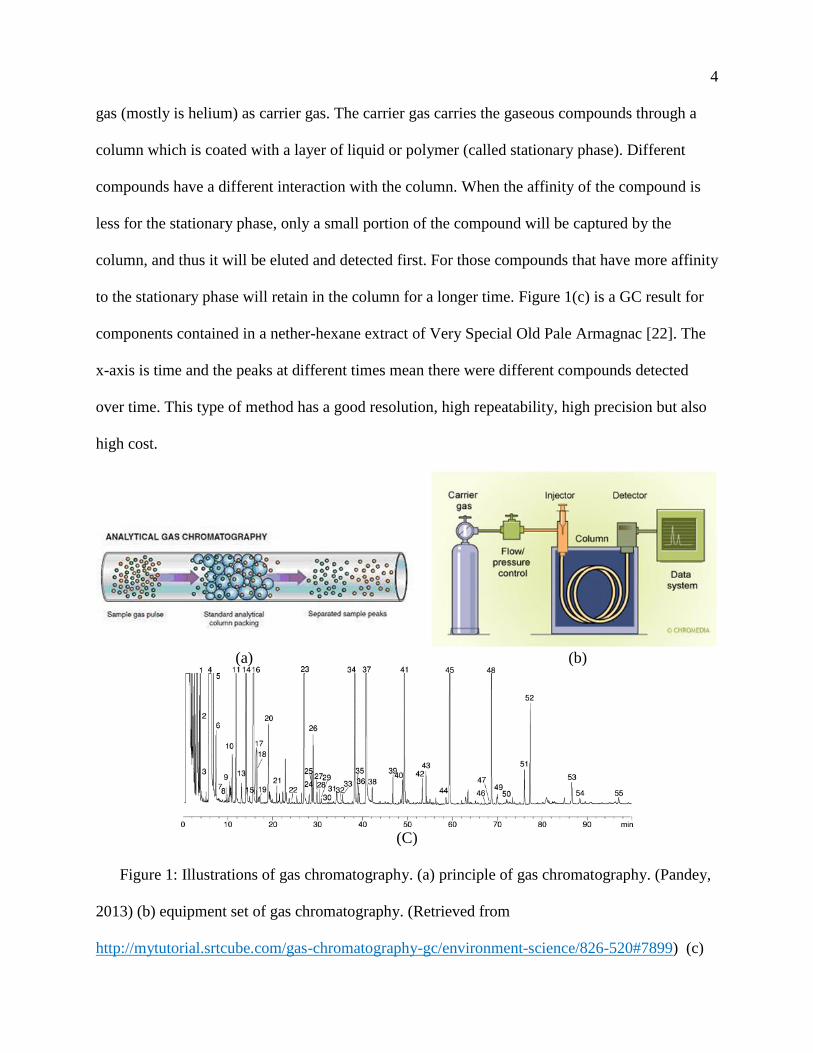
Gas chromatography (GC) is greatly used in laboratory research for segregating and
analyzing compounds that can be vaporized without decomposition [21]. Figure 1 (a) shows the
principle of GC, and Figure 1 (b) shows the GC experiment set. Gas chromatography uses inert
4
gas (mostly is helium) as carrier gas. The carrier gas carries the gaseous compounds through a
column which is coated with a layer of liquid or polymer (called stationary phase). Different
compounds have a different interaction with the column. When the affinity of the compound is
less for the stationary phase, only a small portion of the compound will be captured by the
column, and thus it will be eluted and detected first. For those compounds that have more affinity
to the stationary phase will retain in the column for a longer time. Figure 1(c) is a GC result for
components contained in a nether-hexane extract of Very Special Old Pale Armagnac [22]. The
x-axis is time and the peaks at different times mean there were different compounds detected
over time. This type of method has a good resolution, high repeatability, high precision but also
high cost.
(a) (b)
(C)
Figure 1: Illustrations of gas chromatography. (a) principle of gas chromatography. (Pandey,
2013) (b) equipment set of gas chromatography. (Retrieved from
http://mytutorial.srtcube.com/gas-chromatography-gc/environment-science/826-520#7899) (c)

5
Chromatogram of the extract of an Armagnac by ether hexane (concentration about 3 times);
column FFAP 50 m × 0.22 mm; injection according to splitless mode; temperature
programmation from 40 to 200°C. identification of the peaks: 1, Ethylbutyrate; 2, 2-
methylpropan-1-ol; 3, isoamyl acetate; 4, isoamyl alcohols; 5, ethyl hexanoate; 6, hexyl acetate;
7, styrene; 8, acetoin; 9, ethyl heptanoate; 10, ethyl lactate; 11, hexan-1-ol; 12, trans-hex-3-en-1-
ol; 13, cis-hex-3-en-1-ol; 14, octan-3-ol (internal standard 1); 15, trans-hex-2-en-1-ol; 16, ethyl
octanoate; 17, trans-linalol oxide (furane); 18, cis-linalol oxide (furane), 19, acetic acid; 20,
benzaldehyde; 21, linalol; 22, 2-methylpropionic acid; 23, ethyl decanoate; 24, butyric acid; 25,
3-methylbutyric acid; 26, diethyl succinate; 27, α-terpineol; 28, 1,1,6-trimethyl-l,2-
dihydronaphtalene (TDN); 29, methionol; 30, inconnu; 31, inconnu; 32, damascenone; 33,
phenylethyl acetate; 34, ethyl dodecanoate + hexanoic acid; 35, benzyl alcohol; 36, trans-whisky
lactone; 37, 2-phenylethanol; 38; cis-whisky lactone; 39, 4-ethylgaiacol; 40, ethyl myristate; 41,
octanoic acid; 42, 4-allylgaiacol (eugenol); 43, 4-ethylphenol; 44, ethyl palmitate; 45, decanoic
acid; 46, ethyl stearate; 47, ethyl oleate; 48, dodecanoic acid; 49, ethyl linoleate; 50, ethyl
linolenate; 51, inconnu; 52, myristic acid; 53, palmitic acid; 54, palmitoleic; 55, linoleic acid.
Adapted from [22].
1.3.2 Mass spectrometry
The mass spectrometer ionizes the sample and separates the ions. The separation is
achieved by accelerating the ions and applying an electric or magnetic field, so that the ions with
different mass-to-charge ratio will have different deflection angles [23]. Later, the separated ions
are detected, and are shown as a spectrum with an order on the basis of the ions’ mass-to-charge
ratio. The sample is not limited to gas but could also be solid or liquid. Mass spectrometry has a
very high sensitivity that can reach sub-ppb level [24]. The instrument costs can be from a few
6
thousands to over a hundred thousand US dollars, and operation costs vary from analytes of mass
spectrometry. Mass spectrometry sometimes is combined with gas chromatography to more
accurately analyze the compound.
1.3.3 Spectroscopy
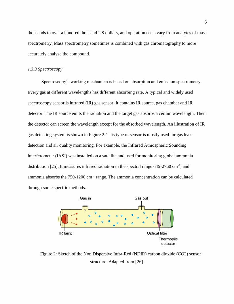
Spectroscopy’s working mechanism is based on absorption and emission spectrometry.
Every gas at different wavelengths has different absorbing rate. A typical and widely used
spectroscopy sensor is infrared (IR) gas sensor. It contains IR source, gas chamber and IR
detector. The IR source emits the radiation and the target gas absorbs a certain wavelength. Then
the detector can screen the wavelength except for the absorbed wavelength. An illustration of IR
gas detecting system is shown in Figure 2. This type of sensor is mostly used for gas leak
detection and air quality monitoring. For example, the Infrared Atmospheric Sounding
Interferometer (IASI) was installed on a satellite and used for monitoring global ammonia
distribution [25]. It measures infrared radiation in the spectral range 645-2760 cm-1, and
ammonia absorbs the 750-1200 cm-1 range. The ammonia concentration can be calculated
through some specific methods.
Figure 2: Sketch of the Non Dispersive Infra-Red (NDIR) carbon dioxide (CO2) sensor
structure. Adapted from [26].

7
1.3.4 Metal oxide semiconductor sensors
Metal oxide semiconductors are the most frequent sensing materials [27]. When the sensor is
exposed to the monitored gas, the oxygen ion (O−) on the surface of the semiconductor is
reduced by the gas (like ammonia). This redox reaction causes the resistance decreasing of the
sensor [27] [28]. Usually, a heat source is added to the sensor to increase its sensitivity.
Semiconductor sensors have a fast reaction time, the normal lower detection limit is about 1ppm,
and the cost is low. Because of this sensing mechanism, the major disadvantage of metal oxide
semiconductor sensors is that it can react with multiple types of gases, so the sensing target is not
selective. The MQ135 ammonia sensor that is used in the experiment is a metal oxide
semiconductor sensor.
1.3.5 Detection tubes
Detection tubes have a low cost, but the accuracy is low [29]. The measuring mechanism of
detection tubes is the coated acid on the tube switch to different colors when reacts with different
concentration of ammonia.
1.3.6 Carbon nanotube sensors
Carbon nanotubes (CNTs) are widely used on gas sensors, temperature/humidity sensors,
stress/strain sensors and biosensors, etc. CNTs are either metallic or semiconducting and their
chemical structure makes them have a large surface-area-to-volume ratio. Because of the unique
properties, CNTs are highly sensitive to some low concentration gases (like alcohol or carbon
dioxide) at room temperature. Moreover, the manufacturing process of CNT sensors eliminates
the need of microfabrication, which is required for semiconductor sensors; the cost of CNT sensors
is lower than semiconductor sensors. The response times of CNT sensors vary from different target

8
gases [30]. A disadvantage of CNT sensor is that it is not selective, which means the response of
the sensor can be the contribution of multiple gases. To increase the specificity and sensitivity,
polymers and/or metal nanoparticles are often added during the manufacturing process.
A lot of researchers have developed different types of ammonia sensors using carbon
nanotubes. Han et al. [31] implemented single-walled carbon nanotubes (SWCNT) on cotton yarns
and used gold (Au) as sensor’s electrodes. The detection limit of their sensor was 8ppm. Goudarzi
et al. [32] doped SWCNTs with lithium and dispersed on interdigitated electrodes using
electrophoresis method. Then the sensors were heat treated at 350°C for 5 hours. This type of
sensor has 29% of sensitivity to 500ppm ammonia at 25°C. Young et al. [33] used thermal
chemical vapor deposition (CVD) method to grow high-density CNTs on oxidized Si substrates.
They tested the sensor with ammonia concentration range from 50ppm to 800ppm. At 50ppm, their
sensor had about 1% sensitivity and about 500 seconds of response time. Randeniya et al. [34]
treated CNT yarns with strong acid or in a pulsed direct-current plasma and used self-fuelled
electrodeposition method to aggregate Au nanoparticles onto CNT yarns. The lowest detectable
ammonia concentration was around 500ppb, and plasma treated and Au decorated sensor samples
were stable, reusable and able to recovery. Chiesa et al. [35] developed a low-cost sensing system.
The ammonia sensor was made by drop casting SWCNT solution on plastic or ceramic substrates,
and connected CNTs and Pt electrodes by Ag contacts. A humidity and temperature sensor was
mounted to the system for calibration purpose. They also developed Expert System algorithms to
help calculate the concentration. Their sensing system can response to about 10 ppb of ammonia
with an error of 20%.

9
1.3.7 Summary
Table 1 list all the ammonia sensing methods discussed above and their advantages and
disadvantages.
Table 1.1. Comparison of ammonia sensing methods
methods Advantage Disadvantage
Gas chromatography
High sensitivity and
specificity
High cost and large in
equipment size
Mass spectrometry
High sensitivity and
specificity
High cost and large in
equipment size
spectroscopy High specificity
High cost and large in
equipment size
Metal oxide
semiconductor sensors
Low cost and quick
response
Low sensitivity and
specificity. Needs to
be heated
Detection tubes
Low cost and short
response time
Low accuracy
Carbon nanotube sensors
Low cost and short
response time
Relatively low
specificity

10
Chapter 2. METHODOLOGY
2.1 EXPERIMENT DESIGN
The experiment consisted of five sections. The first section was the calibration of MQ-135
commercial ammonia sensor. MQ-135 was a semiconductor sensor with a detecting
concentration scope from 10ppm to 300ppm. It was used as a reference sensor when the CNT
sensors were tested in the range from 10ppm to 100ppm.
The second section of the experiment was the preparation of CNT sensors. Three types of
CNT sensors were selected for this experiment. The first type was a pure CNT sensor without
any coating. The second type and the third type were a CNT sensor coated with Nafion and
polyethylenimine (PEI), respectively. In type 2 and type 3, CNT sensors coated with different
concentrations of Nafion and PEI were also made for studying the concentration for a higher
sensitivity (i.e. the sensor will have the best sensitivity). The reason for preparing three different
types of sensors was that CNT sensors could not selectively target one specific gas. To enhance
the specificity, the sensors with different polymers and concentrations were selected. Pure CNT
sensors and Nafion-coated CNT sensors were expected to be p-type [36]. When exposed to
ammonia, the resistance of the sensors increased. The PEI-coated SWCNT sensors were
expected to be n-type and had a decrease in resistance when exposed to ammonia [37]. In a field
test stage, all types of the sensors were used for detecting ammonia.
The third section of the experiment was to test the CNT sensors in a chamber with
different concentrations of ammonia, from 10ppb to 100ppm. The purpose of the chamber test
was to find the best concentration of Nafion and PEI for coating and to characterize the sensor
response. The ppm level test (from 10ppm to 100ppm) was conducted first. The use of MQ-135

11
in this concentration level guaranteed the accuracy when plotted the sensitivity characteristic
curve for SWCNT sensors. Subsequently, the ppb level test (from 10ppb to 10ppm) was
conducted.
The fourth part was in-chamber soil test. The SWCNT sensors were tested with different
amount of fertilized soils. Later these soils were mixed with 1kg of non-fertilized sand to
evaluate the minimum soil-sand ratio that the SWCNT sensors could detect.
The fifth part of the experiment was a drone test. The SWCNT sensors were installed to a
drone. The drone flied to soil that emitted ammonia. By analyzing the different response of the
sensors and comparing the results with chamber test, an estimation of the ammonia concentration
could be given.
The whole experiment used an Arduino Uno board to drive the MQ-135 sensor and
SWCNT sensors. A H&T sensor were added for calibrating the ammonia sensors from humidity
and temperature effect. The data was transported through a Bluetooth kit. The circuit design is
described in Appendix A. The Arduino code could be found in Appendix B.
2.2 PREPARATION OF SWCNT SENSORS
Three types of SWCNT sensors were prepared. Single walled carbon nanotubes (SWCNTs) were
dispersed in SDS at a concentration of 1mg/mL using a sonicator at room temperature for 8
hours. The SWCNTs were spin-coated on a PET film at 6000 rpm for 1 minute. Silver ink was
stamped on the SWCNT surface. The first type of SWCNT sensors were used without any
additional coating layers. The second type of the SWCNT sensors were coated with two different
concentrations of Nafion: 0.1% and 0.5%. The Nafion was spin coated for 10 seconds and heat
treated on 120 °C hot plate for 10 minutes. The third type of the SWCNT sensors were coated
with two different concentrations of PEI: 0.1% and 0.5%. The PEI was doped on the sensors and

12
heat treated on 100 °C hot plate for 10 minutes. The electrodes and the electric wires were
connected by silver paste. Figure 3 shows those 3 different types of sensors. The white parts
were the silver electrodes. This type of design can largely increase the interacting area between
the SWCNTs and target gases.
Figure 3: Three types of SWCNT sensors. Left: pure SWCNT sensor. Middle: Nafion-coated
SWCNT sensor. Right: PEI-coated SWCNT sensor.
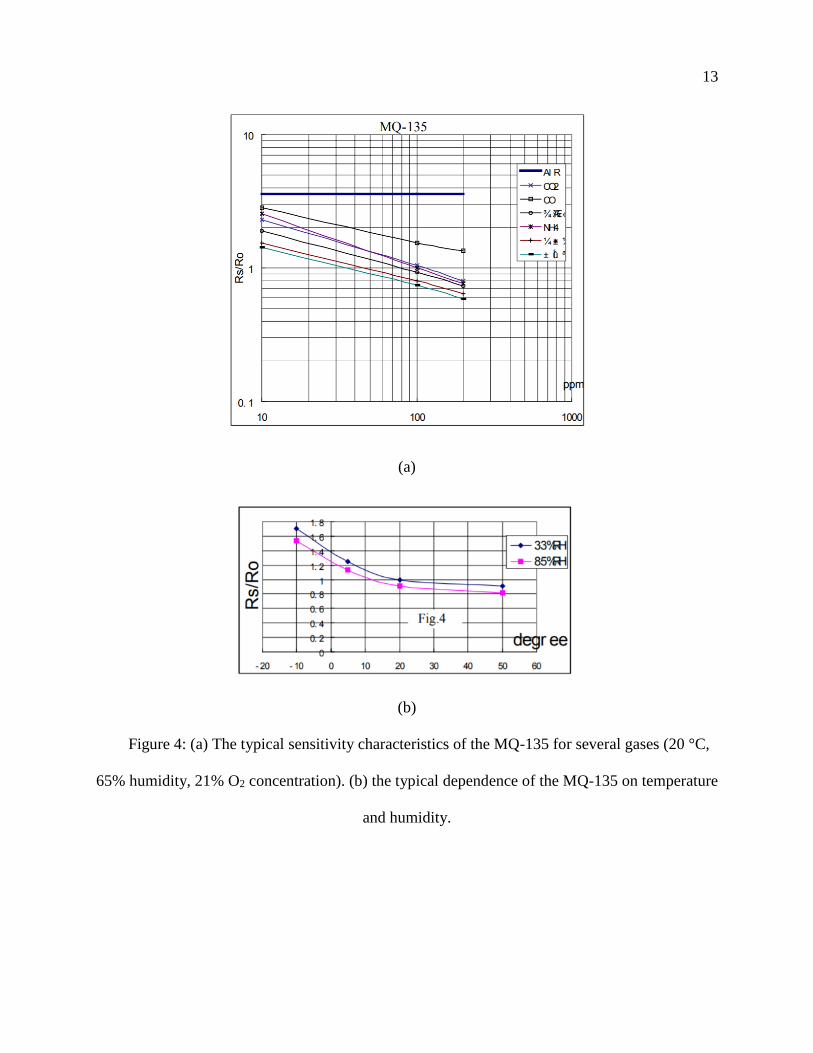
2.3 MQ-135 CALIBRATION
A MQ-135 sensor was calibrated as the manufacturer’s recommendation. There were two
important parameters of the sensor. One is R0, which is the sensor resistance at 100 ppm of
ammonia in the clean air. The other is Rs, which is the sensor resistance at various concentration
of gases. Figure 4(a) shows the calibration curves by the manufacturer. The Rs/R0 ratio changes
are compared with ammonia concentration. A similar curve was expected after the calibration.
13
(a)
(b)
Figure 4: (a) The typical sensitivity characteristics of the MQ-135 for several gases (20 °C,
65% humidity, 21% O2 concentration). (b) the typical dependence of the MQ-135 on temperature
and humidity.

14
Before the calibration, the MQ-135 was pre-heated over 24 hours to reach the best
working condition. MQ-135 was supposed to be placed into a closed chamber and exposed to
100 ppm of ammonia until the reading was stable. This step was to find R0. Limited by the lab
condition, the MQ-135 was only tested under the concentration of 10ppm, 20ppm and 50ppm to
determine the sensitivity characteristic curve. The test readings were already calibrated from
humidity and temperature effect in the Arduino code.
2.4 SWCNT SENSORS’ AMMONIA TEST
The SWCNT sensors’ ammonia test was done by two parts. The first part was ppm level test
(1ppm to 50ppm) with MQ-135 as a reference. The test was done under the concentration of
1ppm, 10ppm, 20ppm and 50ppm in a closed chamber for 650 seconds. (No ammonia from 0-
150 seconds. Ammonia source applied from 150-800 seconds. Ammonia source was removed
after 800 seconds. For rest of the experiment, all the ammonia source, fertilized soil sample, and
soil-sand mixture were applied for 150~800 seconds) The second part was ppb level test (10ppb
to 1ppm). In this range the MQ-135 was not accurate anymore. The test was conducted under the
concentrations of 10ppb, 50ppb and 100ppb in a closed chamber for 650 seconds. Before each
test, the SWCNT sensors’ resistances were waited until they were fully recovered.
2.5 IN-CHAMBER SOIL TEST
The first part of the soil test was to test SWCNT sensors with 0.1g, 0.5g, 1g, 5g, 10g, and 30g
fertilized soil sample contained in a Pyrex ® crystallizing dish (150 x 75 No. 3140). The SWCNT
sensors were tested in a sealed chamber with soil placed. The 0g test was conducted first as a
control group to eliminate the effect from the residual in the chamber that might affect the test
15
results. For each test, the soils were placed in the chamber for 650 seconds and removed
afterwards.
The second part of the soil test was to mix 0g, 0.1g, 0.5g, 1g, 5g, 10g, and 30g fertilized
soil with 1kg of sand which did not have any fertilizer. The mixture was contained in a Pyrex ®
crystallizing dish (150 x 75 No. 3140). The test that with 0g of soil was conducted first as a
control group. For each test, the soil-sand mixtures were placed in the chamber for 650 seconds
and removed afterwards.
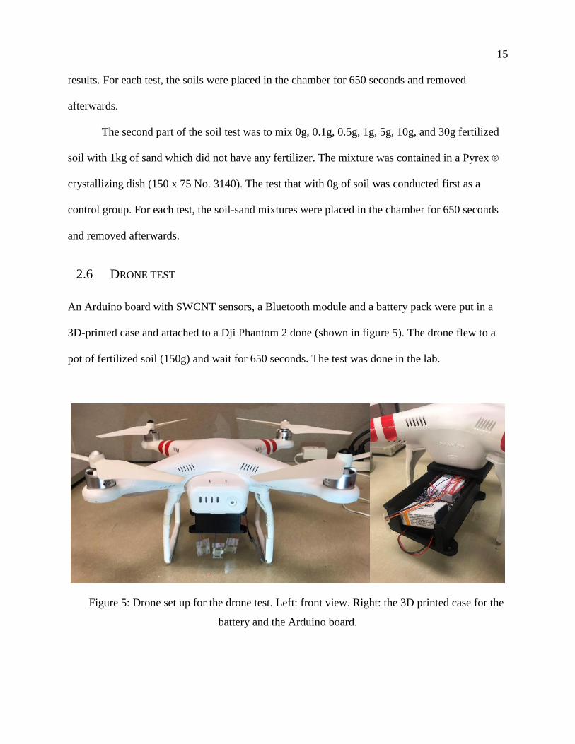
2.6 DRONE TEST
An Arduino board with SWCNT sensors, a Bluetooth module and a battery pack were put in a
3D-printed case and attached to a Dji Phantom 2 done (shown in figure 5). The drone flew to a
pot of fertilized soil (150g) and wait for 650 seconds. The test was done in the lab.
Figure 5: Drone set up for the drone test. Left: front view. Right: the 3D printed case for the
battery and the Arduino board.

16
Chapter 3. RESULTS AND DISCUSSION
3.1 MQ-135 CALIBRATION RESULT AND DISCUSSION
The MQ-135 was calibrated and the calibration curve is shown in figure 5. The environment of
10ppm, 20ppm and 50ppm of ammonia was created for the calibration. The value of R0 was 781
Ohms. The result shows a power relationship. This characteristic curve would be used as a
reference when the SWCNT ammonia sensors were tested.
Figure 6: Calibration curve for MQ-135 ammonia sensor
3.2 SWCNT SENSORS AMMONIA TEST RESULT AND DISCUSSION
3.2.1 1ppm to 50ppm test results
The test result showed that the 0.1% Nafion-coated SWCNT sensors and the 0.1% PEI-coated
SWCNT sensors performed better than 0.5% Nafion-coated SWCNT sensors and the 0.5% PEI-
y = 6.9414x-0.431
R² = 0.9997
1
10
1 10 100
Rs/
R0
concentration (ppm)

17
coated SWCNT sensors, respectively. The rest of the experiment used 0.1% Nafion-coated
SWCNT sensors and the 0.1% PEI-coated SWCNT sensors. Figure 6 (a) and (b) gives the
resistance changes of the pure SWCNT sensors and Nafion-coated SWCNT sensors at 800
seconds of the test. Figure 6 (c) shows the resistance change of a PEI-coated SWCNT sensor
through the test. All types of sensors showed an increase of resistance in the test. Among them,
the pure SWCNT sensors had the largest resistance change. Nafion-coated SWCNT sensors had
a slightly less change than pure SWCNT sensors. PEI-coated sensors had a minor response to
ammonia in comparison to the other two types of sensors.
(a)
y = 0.5402x21.915
R² = 0.9491
10
100
1 1.1 1.2 1.3
Co
nce
ntr
atio
n (
pp
m)
normalized resistance

18
(b)
(c)
Figure 7: 1ppm to 50ppm test results (a) calibration curve for pure SWCNT sensors
resistance changes at 650 seconds. (b) Calibration curve for Nafion-coated SWCNT sensors
y = 0.7645x33.666
R² = 0.94011
10
100
1 1.05 1.1 1.15
Co
nce
ntr
atio
n (
pp
m)
Normalized resistance

19
resistance changes at 650 seconds. (c) PEI-coated SWCNT sensors resistance changes through
the test.
3.2.2 10ppb to 1ppm test results
Figure 7 (a) and (b) gives the resistance changes of the pure SWCNT sensors and Nafion-coated
SWCNT sensors at 800 seconds of the test. Both sensors showed a resistance increase yet the
PEI-coated SWCNT sensors showed a minor resistance decrease. Figure 7 (c) shows the
resistance change of a PEI-coated SWCNT sensor through the test.
(a)

20
(b)
(c)
Figure 8: 10ppb to 1ppm test results (a) calibration curve for pure SWCNT sensors resistance
changes in 650 seconds. (b) Calibration curve for Nafion-coated SWCNT sensors resistance
changes in 650 seconds. (c) PEI-coated SWCNT sensors resistance changes through the test
21
3.2.3 SWCNT sensors ammonia test discussion
Compared with a ppb level test, the ppm level test had a more quantitative characteristic for the
pure SWCNT sensors and the Nafion-coated sensors. Even though the PEI-coated SWCNT sensors
had a minor resistance change, the resistance increased when the ammonia concentration was at
ppm level. The resistance decreased when the ammonia concentration was at ppb level. Especially
for the 100ppb test, the resistance decreased first and later increased. It was speculated that PEI-
coated SWCNT sensors were n-type, but with the effect of high concentration of ammonia, those
sensors might switch to p-type.
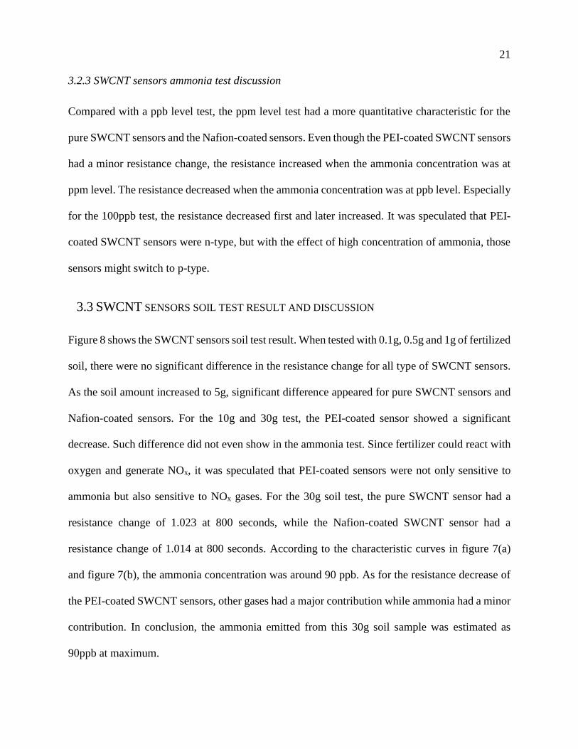
3.3 SWCNT SENSORS SOIL TEST RESULT AND DISCUSSION
Figure 8 shows the SWCNT sensors soil test result. When tested with 0.1g, 0.5g and 1g of fertilized
soil, there were no significant difference in the resistance change for all type of SWCNT sensors.
As the soil amount increased to 5g, significant difference appeared for pure SWCNT sensors and
Nafion-coated sensors. For the 10g and 30g test, the PEI-coated sensor showed a significant
decrease. Such difference did not even show in the ammonia test. Since fertilizer could react with
oxygen and generate NOx, it was speculated that PEI-coated sensors were not only sensitive to
ammonia but also sensitive to NOx gases. For the 30g soil test, the pure SWCNT sensor had a
resistance change of 1.023 at 800 seconds, while the Nafion-coated SWCNT sensor had a
resistance change of 1.014 at 800 seconds. According to the characteristic curves in figure 7(a)
and figure 7(b), the ammonia concentration was around 90 ppb. As for the resistance decrease of
the PEI-coated SWCNT sensors, other gases had a major contribution while ammonia had a minor
contribution. In conclusion, the ammonia emitted from this 30g soil sample was estimated as
90ppb at maximum.
22
(a)
(b)

23
(c)
Figure 9: Fertilized soil test results. (a) Pure SWCNT sensors resistance changes. (b) Nafion-
coated SWCNT sensors resistance changes. (c) PEI-coated SWCNT sensors resistance changes.
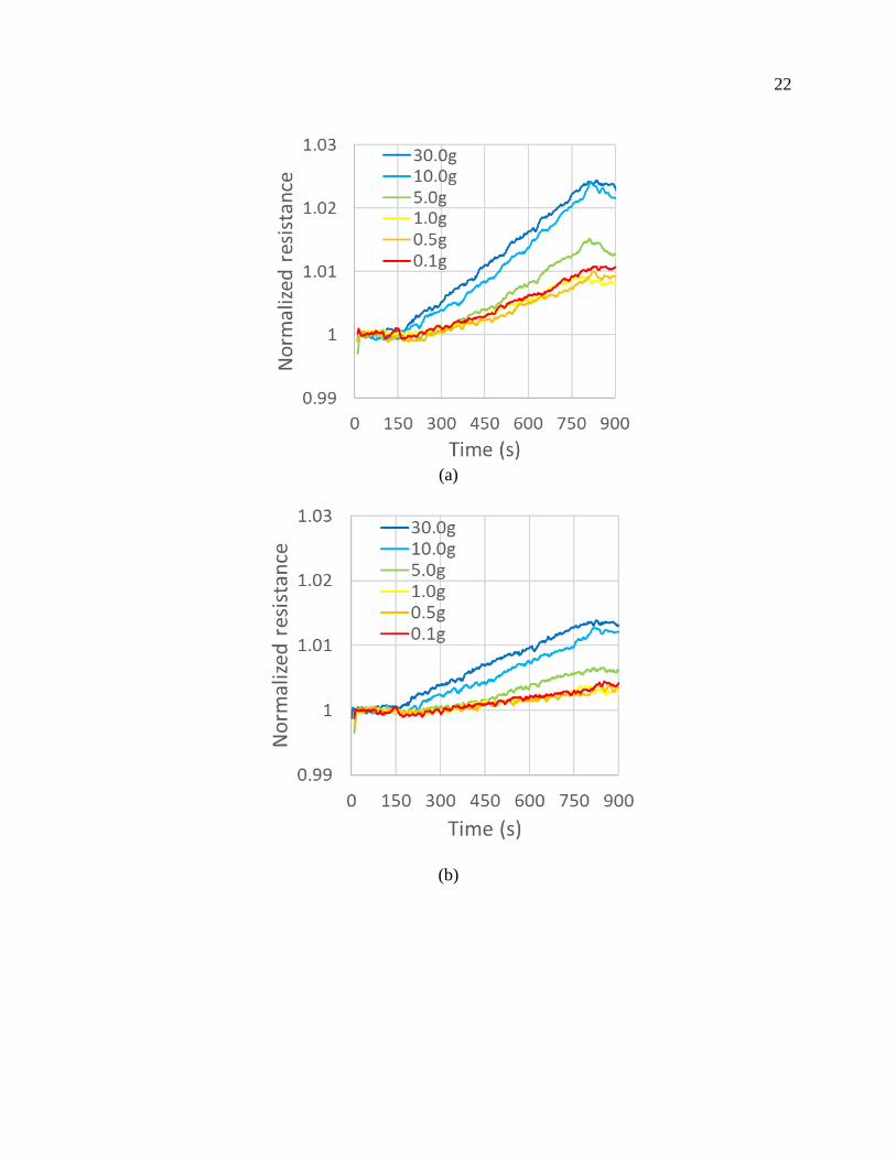
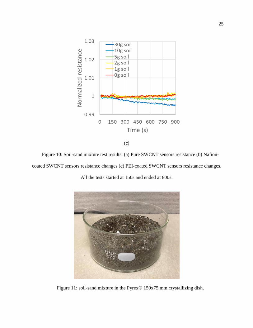
3.4 SWCNT SENSORS SOIL-SAND MIXTURE TEST RESULT AND DISCUSSION
The soil-sand mixture test result is shown in figure 9. The significant difference in resistance
change appeared after the 10g of soil mixed with the 1kg sand for the pure SWCNT sensor and the
Nafion-coated sensor. As for the PEI-coated sensor, the decrease for 30g mixture test might be
contributed by ammonia and NOx gases. Even though there was a decrease for 30g mixture test,
the decrease was much smaller than that from the 30g soil test. It was speculated that the sand in
the mixture (the mixture is shown in figure 10) blocked some of the gas diffusion from the soil
(ammonia and NOx). The depth of the mixture was 3.7 cm.

24
(a)
(b)
25
(c)
Figure 10: Soil-sand mixture test results. (a) Pure SWCNT sensors resistance (b) Nafion-
coated SWCNT sensors resistance changes (c) PEI-coated SWCNT sensors resistance changes.
All the tests started at 150s and ended at 800s.
Figure 11: soil-sand mixture in the Pyrex® 150x75 mm crystallizing dish.

26
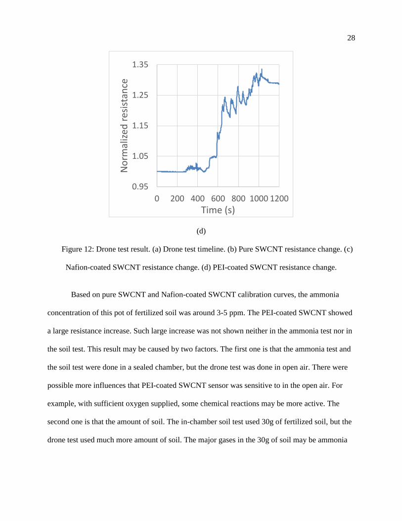
3.5 DRONE TEST RESULT AND DISCUSSION
Figure 11 gives the drone test result. The drone was at still from 0 to 300 seconds. It was
powered up and flew to the soil from 300 seconds to 400 seconds. Then it landed on the soil and
powered off from 400 to 1050 seconds. The timeline is shown in figure 11(a). From the test
result, it shows that the airflow generated by the drone had non-neglectable influence on the
sensors. The pure SWCNT sensor had a resistance change of around 10-12%, the Nafion-coated
SWCNT sensor had a resistance change of around 3-5%, and the PEI-coated SWCNT sensor had
a resistance change of around 34% with a lot of large fluctuations during the test.
(a)

27
(b)
(c)
28
(d)
Figure 12: Drone test result. (a) Drone test timeline. (b) Pure SWCNT resistance change. (c)
Nafion-coated SWCNT resistance change. (d) PEI-coated SWCNT resistance change.
Based on pure SWCNT and Nafion-coated SWCNT calibration curves, the ammonia
concentration of this pot of fertilized soil was around 3-5 ppm. The PEI-coated SWCNT showed
a large resistance increase. Such large increase was not shown neither in the ammonia test nor in
the soil test. This result may be caused by two factors. The first one is that the ammonia test and
the soil test were done in a sealed chamber, but the drone test was done in open air. There were
possible more influences that PEI-coated SWCNT sensor was sensitive to in the open air. For
example, with sufficient oxygen supplied, some chemical reactions may be more active. The
second one is that the amount of soil. The in-chamber soil test used 30g of fertilized soil, but the
drone test used much more amount of soil. The major gases in the 30g of soil may be ammonia
0.95
1.05
1.15
1.25
1.35
0 200 400 600 800 1000 1200
No
rmal
ized
res
ista
nce
Time (s)

29
and NOx. For large amount of soil, due to the microbe activity, gases other than ammonia and
NOx may become major.
3.6 SUMMERY
Using single walled carbon nanotube (SWCNT) sensors, ammonia and NOx gases were detected
in sand mixed with fertilizer. The developed sensor array was integrated into a drone for gas
detection in soil. In the experiment, the combination of pure SWCNT sensor, Nafion-coated
SWCNT sensor and PEI-coated SWCNT sensor had a relatively accurate characteristic curve in
the ammonia concentration range of 1 ~ 50 ppm. When the concentration range decreased to
10ppb to 1ppm, the characteristic curve was not highly accurate, but still could provide a
concentration range.
Regarding the recovery time of the SWCNT sensors, the larger resistance change required
the longer recovery time. For example, when tested with 50ppm of ammonia, the recovery time
was over 24 hours. As for the low concentration, the recovery time was much shorter. The sensors
required about 10 minutes to recovery after the 10ppb ammonia test.
As for the soil test, it was found that this sensor set was able to provide a reference value
of the ammonia concentration in soil. According to the soil test, the minimum concentration that
the sensors had response was around 50 ppb. When mixed with sand, the detection limit of the
SWCNT sensor was 1:100 of the minimum soil-sand ratio. Even though the PEI-coated SWCNT
sensor’s responses might not only because of ammonia as discussed earlier, a possible maximum
ammonia concentration could still be estimated by comparing the results of pure SWCNT sensor
and Nafion-coated SWCNT sensor with their calibration curves. Since this set of sensors would
be used as a low-cost ammonia monitor for agriculture, this accuracy should be good enough to
detect the ratio of fertilizer to sand.

30
To further improve the performance of these sensors, more experiment needs to be done
to determine the influential factors for a PEI-coated SWCNT sensor. The design of the 3D-
printed case for the drone test needs to be improved to reduce the effect of the airflow generated
by the drone.

31
REFERENCES
[1] U. Diaz, V. Saliba-Colombani, O. Loudet, P. Belluomo, L. Moreau, F. Daniel-Vedele, et
al., "Leaf yellowing and anthocyanin accumulation are two genetically independent
strategies in response to nitrogen limitation in Arabidopsis thaliana," Plant and Cell
Physiology, vol. 47, pp. 74-83, Jan 2006.
[2] T. Kraiser, D. E. Gras, A. G. Gutierrez, B. Gonzalez, and R. A. Gutierrez, "A holistic
view of nitrogen acquisition in plants," Journal of Experimental Botany, vol. 62, pp.
1455-1466, Feb 2011.
[3] C. W. Liu, Y. Sung, B. C. Chen, and H. Y. Lai, "Effects of Nitrogen Fertilizers on the
Growth and Nitrate Content of Lettuce ( Lactuca sativa L.)," International Journal of
Environmental Research and Public Health, vol. 11, pp. 4427-4440, Apr 2014.
[4] G. P. Robertson and P. M. Vitousek, "Nitrogen in Agriculture: Balancing the Cost of an
Essential Resource," in Annual Review of Environment and Resources. vol. 34, ed Palo
Alto: Annual Reviews, 2009, pp. 97-125.
[5] I. Cechin and T. D. Fumis, "Effect of nitrogen supply on growth and photosynthesis of
sunflower plants grown in the greenhouse," Plant Science, vol. 166, pp. 1379-1385, May
2004.
[6] D. L. Zhao, K. R. Reddy, V. G. Kakani, J. J. Read, and G. A. Carter, "Corn (Zea mays L.)
growth, leaf pigment concentration, photosynthesis and leaf hyperspectral reflectance
properties as affected by nitrogen supply," Plant and Soil, vol. 257, pp. 205-217, Nov
2003.
[7] N. Anderson, R. Strader, and C. Davidson, "Airborne reduced nitrogen: ammonia
emissions from agriculture and other sources," Environment International, vol. 29, pp.
277-286, Jun 2003.
[8] R. Conrad, W. Seiler, and G. Bunse, "FACTORS INFLUENCING THE LOSS OF
FERTILIZER NITROGEN INTO THE ATMOSPHERE AS N2O," Journal of
Geophysical Research-Oceans, vol. 88, pp. 6709-6718, 1983.
[9] O. E. Sala, F. S. Chapin, J. J. Armesto, E. Berlow, J. Bloomfield, R. Dirzo, et al.,
"Biodiversity - Global biodiversity scenarios for the year 2100," Science, vol. 287, pp.
1770-1774, Mar 2000.
[10] L. Jones, A. Provins, M. Holland, G. Mills, F. Hayes, B. Emmett, et al., "A review and
application of the evidence for nitrogen impacts on ecosystem services," Ecosystem
Services, vol. 7, pp. 76-88, Mar 2014.
[11] S. M. McGinn and H. H. Janzen, "Ammonia sources in agriculture and their
measurement," Canadian Journal of Soil Science, vol. 78, pp. 139-148, Feb 1998.
[12] J. N. Galloway, F. J. Dentener, D. G. Capone, E. W. Boyer, R. W. Howarth, S. P.
Seitzinger, et al., "Nitrogen cycles: past, present, and future," Biogeochemistry, vol. 70,
pp. 153-226, Sep 2004.
[13] X. Zhu, W. Zhang, H. Chen, and J. Mo, "Impacts of nitrogen deposition on soil nitrogen
cycle in forest ecosystems: A review," Acta Ecologica Sinica, vol. 35, pp. 35-43,
2015/06/01/ 2015.
[14] N. B. Dise, M. Ashmore, S. Belyazid, A. Bleeker, R. Bobbink, W. de Vries, et al.,
"Nitrogen as a threat to European terrestrial biodiversity," in The European Nitrogen
Assessment: Sources, Effects and Policy Perspectives, A. Bleeker, B. Grizzetti, C. M.
32
Howard, G. Billen, H. van Grinsven, J. W. Erisman, et al., Eds., ed Cambridge:
Cambridge University Press, 2011, pp. 463-494.
[15] J. A. Silva, R. S. Uchida, U. o. H. a. M. C. o. T. Agriculture, and H. Resources, Plant
Nutrient Management in Hawaii's Soils: Approaches for Tropical and Subtropical
Agriculture: College of Tropical Agriculture & Human Resources, University of Hawaii
at Manoa, 2000.
[16] K. W. T. Goulding, "Soil acidification and the importance of liming agricultural soils
with particular reference to the United Kingdom," Soil Use and Management, vol. 32, pp.
390-399, Sep 2016.
[17] L. Xiankai, M. Jiangming, and D. Shaofeng, "Effects of nitrogen deposition on forest
biodiversity," Acta Ecologica Sinica, vol. 28, pp. 5532-5548, 2008/11/01/ 2008.
[18] N. Vanbreemen, C. T. Driscoll, and J. Mulder, "ACIDIC DEPOSITION AND
INTERNAL PROTON SOURCES IN ACIDIFICATION OF SOILS AND WATERS,"
Nature, vol. 307, pp. 599-604, 1984.
[19] T. Dirnbock, G. Proll, K. Austnes, J. Beloica, B. Beudert, R. Canullo, et al., "Currently
legislated decreases in nitrogen deposition will yield only limited plant species recovery
in European forests," Environmental Research Letters, vol. 13, Dec 2018.
[20] J. N. Galloway, A. R. Townsend, J. W. Erisman, M. Bekunda, Z. C. Cai, J. R. Freney, et
al., "Transformation of the nitrogen cycle: Recent trends, questions, and potential
solutions," Science, vol. 320, pp. 889-892, May 2008.
[21] W. Q. AL-Bukhaiti, A. Noman, A. S. Qasim, and A. Al-Farga, "Gas Chromatography :
Principles , Advantages and Applications in Food Analysis," 2017.
[22] A. Bertrand, "BRANDY AND COGNAC | Armagnac, Brandy, and Cognac and their
Manufacture," in Encyclopedia of Food Sciences and Nutrition (Second Edition), B.
Caballero, Ed., ed Oxford: Academic Press, 2003, pp. 584-601.
[23] B. Boggess, "Mass Spectrometry Desk Reference (Sparkman, O. David)," Journal of
Chemical Education, vol. 78, p. 168, 2001/02/01 2001.
[24] J. B. Nowak, J. A. Neuman, K. Kozai, L. G. Huey, D. J. Tanner, J. S. Holloway, et al.,
"A chemical ionization mass spectrometry technique for airborne measurements of
ammonia," Journal of Geophysical Research-Atmospheres, vol. 112, Feb 2007.
[25] L. Clarisse, C. Clerbaux, F. Dentener, D. Hurtmans, and P. F. Coheur, "Global ammonia
distribution derived from infrared satellite observations," Nature Geoscience, vol. 2, pp.
479-483, Jul 2009.
[26] L. B. Mendes, N. W. M. Ogink, N. Edouard, H. J. C. van Dooren, I. D. F. Tinoco, and J.
Mosquera, "NDIR Gas Sensor for Spatial Monitoring of Carbon Dioxide Concentrations
in Naturally Ventilated Livestock Buildings," Sensors, vol. 15, pp. 11239-11257, May
2015.
[27] X. Liu, S. T. Cheng, H. Liu, S. Hu, D. Q. Zhang, and H. S. Ning, "A Survey on Gas
Sensing Technology," Sensors, vol. 12, pp. 9635-9665, Jul 2012.
[28] B. Timmer, W. Olthuis, and A. van den Berg, "Ammonia sensors and their applications -
a review," Sensors and Actuators B-Chemical, vol. 107, pp. 666-677, Jun 2005.
[29] B. D. Hale, B. Fairchild, J. Worley, L. Harper, C. Ritz, M. Czarick, et al., "Comparison
of ammonia measurement methods inside and outside tunnel-ventilated broiler houses,"
Journal of Applied Poultry Research, vol. 19, pp. 245-262, Sep 2010.
[30] K. G. Ong, K. F. Zeng, and C. A. Grimes, "A Wireless, Passive Carbon Nanotube-Based
Gas Sensor," Ieee Sensors Journal, vol. 2, pp. 82-88, Apr 2002.
33
[31] J. W. Han, B. Kim, J. Li, and M. Meyyappan, "A carbon nanotube based ammonia sensor
on cotton textile," Applied Physics Letters, vol. 102, May 2013.
[32] F. Goudarzi, M. R. Vaezi, and A. Kazemzadeh, "A novel single wall carbon nanotubes-
based sensor doped with lithium for ammonia gas detection," Journal of Ceramic
Processing Research, vol. 13, pp. 612-616, Oct 2012.
[33] S. J. Young and Z. D. Lin, "Ammonia gas sensors with Au-decorated carbon nanotubes,"
Microsystem Technologies-Micro-and Nanosystems-Information Storage and Processing
Systems, vol. 24, pp. 4207-4210, Oct 2018.
[34] L. K. Randeniya, P. J. Martin, A. Bendavid, and J. McDonnell, "Ammonia sensing
characteristics of carbon-nanotube yarns decorated with nanocrystalline gold," Carbon,
vol. 49, pp. 5265-5270, Dec 2011.
[35] M. Chiesa, F. Rigoni, M. Paderno, P. Borghetti, G. Gagliotti, M. Bertoni, et al.,
"Development of low-cost ammonia gas sensors and data analysis algorithms to
implement a monitoring grid of urban environmental pollutants," Journal of
Environmental Monitoring, vol. 14, pp. 1565-1575, Jun 2012.
[36] H. Z. Geng, K. K. Kim, C. Song, N. T. Xuyen, S. M. Kim, K. A. Park, et al., "Doping
and de-doping of carbon nanotube transparent conducting films by dispersant and
chemical treatment," Journal of Materials Chemistry, vol. 18, pp. 1261-1266, 2008.
[37] S. L. Kim, K. Choi, A. Tazebay, and C. Yu, "Flexible Power Fabrics Made of Carbon
Nanotubes for Harvesting Thermoelectricity," Acs Nano, vol. 8, pp. 2377-2386, Mar
2014.

34
APPENDIX A

35
APPENDIX B
Arduino code for MQ-135 calibration:
#include "MQ135.h"
#include <DHT.h>
#define DHTPIN 2 // modify to the pin we connected
#define DHTTYPE DHT21 // DHT 21 (AM2301)
DHT dht(DHTPIN, DHTTYPE);
#define PIN_MQ135 A2
MQ135 mq135_sensor = MQ135(PIN_MQ135);
void setup() {
Serial.begin(9600);
}
void loop() {
//read humidity and temperature form the h&t sensor
float humidity = dht.readHumidity();
float temperature = dht.readTemperature();
//get the MQ135 sensor resistance
float resistance = mq135_sensor.getResistance();
//get the correction factor
float CorrectionFactor = mq135_sensor.getCorrectionFactor(temperature,humidity);
//get the corrected resistance
float CorrectedResistance = mq135_sensor.getCorrectedResistance(temperature,humidity);

36
//print out the results
Serial.print("\t temperature: ");
Serial.print(temperature);
Serial.print("\t humidity: ");
Serial.print(humidity);
Serial.print("\t CorrectedResistance: ");
Serial.print(CorrectedResistance,5);
Serial.println();
delay(1000)
}

37