- Canadian Environmental Assessment ... · This report used AFT Fathom software to calculate the...
136
Transcript of - Canadian Environmental Assessment ... · This report used AFT Fathom software to calculate the...

sinclairr
Typewritten Text
<original signed by>

sinclairr
Typewritten Text
<original signed by>
sinclairr
Typewritten Text
<original signed by>

E-FILE
IN THE MATTER OF NEB FILE: OF-Fac-Oil-N304-2010-01 01
NORTHERN GATEWAY PIPELINES INC.
Application for ENBRIDGE NORTHERN GATEWAY PROJECT
Certificate of Public Convenience and Necessity
OH-4-2011
WRITTEN EVIDENCE OF THE INTERVENOR
C.J. PETER ASSOCIATES ENGINEERING Enbridge Northern Gateway Pipeline Project Energy Return on Investment Executive Summary Energy return on energy investment (EROI or EROEI) is becoming an accepted approach to determining the viability of energy projects. Our goal was to place an energy cost on an entire production/transportation cycle for the proposed Enbridge Northern Gateway Pipeline Project including extraction and pipeline transport in Alberta and BC, as well as tanker transport and refining of diluted bitumen into a crude oil equivalent by refineries off-shore. The cycle has condensate pumped from gas fields in the area of Dampier, Australia. There, the condensate is shipped to Kitimat, BC. The condensate is transported by pipeline to the Athabascan oil sands. Extracted Bitumen is diluted with the condensate and pumped to Kitimat. There, the bitumen blend is transported by tanker to Dalian, China. Refineries there produce a crude oil equivalent and return empty tankers to Kitimat and Dampier. Energy expended in the extraction and transport stages of the cycle were found to be 7,854 kJ/L for extraction, 259.6 kJ/L for pipeline transport, 341.6 kJ/L for tanker transport for a total of 8,455.6 kJ/L. Diluent recovery contributed 2,970.7 kJ/L and hydrogen addition contributed 4,616.2 kJ/L. Total energy expended amounted to 16,042.1 kJ/L equivalent of conventional crude oil. An EROI of 2.41:1 was calculated and found to be on the lower side of EROIs reported for other Athabascan oil sands projects.

1. Reason for making presentation Energy return on energy investment (EROI or EROEI) is becoming an accepted approach to determining the viability of energy projects1. Simply stated: EROI = Energy-out / Energy-in where energy-out is the energy content of the usable refined oil products (e.g., gasoline, diesel, distillate, jet fuel) and energy-in is the energy expended in extracting, transporting, and refining such products. Mathematically, it is the ratio of the amount of usable energy acquired from a particular resource to the energy expended to acquire that energy. The proposed Enbridge Northern Gateway Pipeline is a significant energy delivery project whose impact will be felt not only within Alberta and BC but throughout the Pacific Rim whose nations it will impact, and therefore deserves consideration by an EROI study. 2. Boundaries of the EROI Study Setting the boundaries for an EROI depends on the goals of the study. EROI may at an extreme include renewal of the basic infrastructure that supports a proposed project or it may be less inclusive and be constrained to a cycle of production of bitumen/condensate and its transport. Our goal is to place an energy cost on the extraction, pumping, shipping, and refining of bitumen/condensate (also known as diluted bitumen or "dilbit") into an energy end product. There are various ways to delimit a process. Various practitioners of EROI may go into different stages of the process studied. We have defined our study within temporal and geographical boundaries: • The temporal boundary begins at the time the pipelines (1 for diluted bitumen and 1for condensate) are commissioned and ends before their service life of the pipeline has ended. The temporal boundary excludes the construction, maintenance and decommissioning of the pipeline. This is primarily because factors that are the same for conventional crude oil and diluted bitumen distribution networks need not be factored into the EROI. • The input end of the system is the acquisition of the condensate at the start of the bitumen/condensate transportation cycle. The most probable source of condensate listed in Enbridge Northern Gateway’s response to JRP Information Request 2.3 is the offshore NW Australian Shelf. This condensate would be piped to the port of Dampier on the coast of Australia. However, Enbridge also lists the LNG port of Ras Laffan in Qatar as a possible source of condensate. • At the end of the bitumen/condensate transportation cycle, the output end of the system is the delivery and refining of diluted bitumen into an energy end product, which for the purpose of this study is the pure bitumen from which condensate has been removed. The most probable locations for these are refineries in the area of Dalian, China.
Since Enbridge Northern Gateway’s application lists no probable destination for diluted bitumen, this location has been chosen after discussion with Petro-China’s management consultant2 Bearing Point. 1 Murphy, D. J. and Hall, C. A. S. (2010) Annals of the New York Academy of Sciences 1185:102-118. 2 Jonathan W. Peter, Personal communication.

Since 1984 Dalian has been a free port and the zone around it designated a Special Economic Zone within the PRC, encouraging the development of privately owned ‘tea pot’ refineries with the flexibility to refine a wide range of inputs into a wide range of output products. This has made Dalian an attractive destination for products like diluted bitumen that required the condensate fraction to be removed in a diluent recovery unit and the hydrogen content enriched prior to refining. After a disastrous series of refinery explosions and fires in 2010-11, these small refineries are now being phased out and replaced with larger private and state owned refining and petrochemical processing plants. The geographical boundary of our study extends well beyond BC and Alberta where the proposed pipeline is to be built. There is a strong case for including extraction, pumping, shipping and the diluent recovery section of refining in the EROI calculation. Factors to consider are: • The viability of the Enbridge pipeline will depend on the maintenance and security of Middle Eastern and Australian sources of condensate, its transport via pipeline and oil tankers to Chinese refineries, and the continued demand for diluted bitumen by these refineries. It follows that if these components are essential to the viability of the pipeline, they are also integral to the EROI calculation. • Low Carbon Fuel Standards have already been adopted in California and BC and energy and emission accounting will be increasingly required for transportation fuels in other jurisdictions. • Various international protocols (i.e., successors to Kyoto) that address climate change will make an overall calculus of energy consumption and carbon emissions part of the review process for future Canadian energy delivery projects. 3. Assumptions of the EROI Study We have made assumptions concerning: • The source and principal means of extraction of bitumen - Steam Assisted Gravity Drainage (SAGD) from the Athabascan oil sands. • The destination of and route taken by the bitumen blend - Athabascan oil sands from Fort McMurray to Bruderheim AB, to Kitimat BC, to Dalian China. • The source of condensate – the Australian Northwest Shelf. • The route taken by the condensate: Piped from offshore gas fields to Dampier, Australia, thence by tanker to Hong Kong, China to Kitimat, BC. By pipeline to Bruderheim, AB and on to Fort McMurray, AB. • Tanker size - shipping by Suezmax oil tanker (166,300 DWT). • The component of the condensate that is returned to the condensate stream is 70 out of 270 litres (26%) which is recycled at the refineries in China.

4. The Production/Transportation Cycle Model The presentation of results follows the bitumen/condensate production/transportation cycle. The cycle has condensate (1 unit) pumped from gas fields on the NW Australian shelf to the port of Dampier, Australia. There, the condensate is shipped to Hong Kong and thence to Kitimat, BC. The condensate is pumped to Bruderheim, AB and thence to Fort McMurray. Bitumen is extracted from the Athabascan oil sands, and diluted with condensate (70% bitumen/30% diluent). The diluted bitumen is pumped to Bruderheim, and thence to Kitimat, BC. There, the bitumen blend is shipped to Dalian, China (2.7 units). Refineries there separate condensate from the bitumen and return 1.7 tankers (empty) to Kitimat and 1.0 tankers (empty) to Dampier. Calculation of pumping energy used Enbridge’s revised pump sizes listed in ENG Response to JRP Information Request No.3. It appears that pumps other than the spare pumps will run fully loaded during Phase I winter operations when dilbit and condensate viscosities are higher and will only be operating partially loaded (with impeller or volute changes) after additional pumping stations are brought on line in subsequent Phases of operation. Reference was made to the 2010 report Low Carbon Fuel Standard “Crude Shuffle” Greenhouse Gas Impacts Analysis3. This report used AFT Fathom software to calculate the pumping energy for the Northern Gateway Pipeline, but the assumed conditions were 10oC ambient temperature and an operating pressure of 1,200 psi. The use of Enbridge’s published Phase I pump data was found to result in a better estimate of pumping energy. The energy consumed at each stage of production is kJ/L of the transported product (e.g., diluted bitumen blend). Once the product is unloaded, the first stage of refining is the removal of condensate in the Diluent Recovery Unit. The energy consumed at the refinery in diluent recovery and hydrogen enrichment is needed to render it equivalent in energy content and refineability to conventional crude. 5. Presentation of Overall Results Total Operating Energy Expended by Enbridge Northern Gateway Project in KiloJoules per Litre of Dilbit Delivered to Refineries at Dalian China:
• Extraction Energy 7,854 kJ/L • Pipeline Transport
Condensate Pumping 378.32 kJ/L x 30% = 113.5 kJ/L Dilbit Pumping 208.66 kJ/L x 70% = 146.1 kJ/L
• Tanker Transport
Condensate Full 92.0 kJ/L Dilbit Full 146.4 kJ/L Dilbit Empty 68.8 kJ/L Condensate Empty 34.4 kJ/L
TOTAL: 8,455.2 kJ/L
____________________________ 3 Barr Engineering Ltd., June 2010

But 1 Litre of Dilbit Reduces to 0.74 Litres of Refineable Product when the Diluent is Recovered and Returned to the Condensate Stream at the Refinery. Operating Energy From Diluent Recovery Added per Litre of Refineable Product:
• Diluent Recovery 8,455.2 kJ/L - 8,455.2 kJ/L = 2,970.7 kJ/L
0.74
Because Diluted Bitumen is Low on Hydrogen, Hydrogen is Added During the refining Process in the Form of 23.9 Fuel Oil Equivalent Barrels of Natural Gas per 200 Barrels of Refineable Product.
• Hydrogen Addition 23.9 x 6,142,000 kJ Barrel = 4,616.2 kJ/L 200 x 159 L Barrel
Therefore, Total Energy Required per Litre to Deliver Product to the Chinese Refinery and Render it Suitable for Refining into Fuel and Petrochemicals:
• Total Extraction and Delivery 8,455.2 kJ/L • Diluent Recovery 2,970.7 kJ/L • Hydrogen Addition 4,616.2 kJ/L
TOTAL ENERGY EXPENDED PER 16,042.1 kJ/L LITRE EQUIVALENT OF CONVENTIONAL CRUDE:
6. ENERGY RETURN ON INVESTMENT:
6,142.0 MJ Barrel L 1,000 kJ = 2.41 159 L Barrel 16,042.1 kJ MJ
7. Discussion Extraction of bitumen from the Athabascan oil sands and pre-refining at Dalian refineries are the two most significant contributors to overall energy consumption. They amount to 49% and 47%, respectively, of total energy expenditure. Pre-refining consists of diluent recovery and hydrogen enrichment. The density of energy consumed per Litre of bitumen is increased by the process of diluent recovery. The energy consumed by hydrogen enrichment is provided by natural gas. Removing the condensate at the end of the transport/production cycle contributes 18.5% of total energy expenditure and hydrogen enrichment contributes 28.7% of total energy expenditure. These sources of energy consumption are followed by tanker and pipeline transport at 2.1% and1.6%, respectively, of total energy expenditure. There is a significant cost in energy attributable to the dilution and reconcentration process. Diluting the bitumen contributes 1.5% (at the extraction end) and undiluting it 18.5% (at the refinery end) of the overall energy expenditure of the production/transport process.

Shipping and pumping consume an order of magnitude less energy than extraction of the bitumen and recovery of the diluent. However, transporting condensate and empty tankers about the Pacific contributes 67% to ocean transport costs. Pumping condensate to the source of bitumen contributes 43.7% to overall pumping costs. An EROI of 2.41 to 1 was calculated for the overall operation of the Enbridge Northern Gateway Project. 7. Conclusion The boundaries set for the project went from extraction of the bitumen to the production of a product equivalent to conventional crude oil. A range of views is to be found among practitioners of EROI as to the upper and lower bounds of an EROI study. The EROI obtained would have been lower had the study expanded beyond its present boundaries. It is useful to view the Gateway Pipeline EROI from the perspective of other EROIs. Our EROI may be compared to the other analyeses of oil sands EROI (Table 1). The calculated EROI is on the lower side of the generally observed range.
Table 1. Other Analyses of Oil Sands EROI An EROI of 2.41:1 should be important evidence as the JRP decides on the energetic and economic viability of the proposed project.

IN THE MATTER OF NEB FILE:
OF-Fac-Oil-N304-2010-01 01
NORTHERN GATEWAY PIPELINES INC.
Application for ENBRIDGE NORTHERN GATEWAY PROJECT
Certificate of Public Convenience and NecessityHearing Order OH-4-2011
ORAL EVIDENCE OF THE INTERVENORC.J. PETER ASSOCIATES ENGINEERING
01/18/2012

CJPAE C.J. PETER ASSOCIATES ENGINEERINGMECHANICAL BUILDING SERVICES CONSULTING ENGINEERS
Mechanical engineering consulting firm located in Prince George, B.C.
Providing professional mechanical engineering services since 1994 for office, commercial, institutional, health care and remote facilities.
Principal of the firm, C.J. Peter, P.Eng, has over 25 years experience in building mechanical design, energy modelling and energy conservation engineering.
Design and retrofit of major buildings throughout Nunavut, h b lb d h l fNorthwest Territories, Manitoba, Alberta and B.C., in the last two of
which jurisdictions registered professional status is maintained.
LEED7 AP and Member of US Green Building Council since 2008.
The 'USGBC Member Logo' is a trademark owned by the U.S. Green Building Council and is used by permission. The logo signifies only
“LEED Accredited Professional” and the related acronym, and the Legacy LEED AP logo are trademarks owned by the U.S. Green Building Council and are awarded to individuals under license by the Green Building Certification Institute.
01/18/2012 2C.J. PETER ASSOCIATES ENGINEERING
g y g y p g g ythat CJPAE is a USGBC member; USGBC does not review, certify, or endorse the products or services offered by its members.

BASICS
Energy OutEnergy In
EROI = gy
where energy-out is the energy content of the usable refinedoil products (e.g., gasoline, diesel, distillate, jet fuel) andenergy-in is the energy expended in extracting, transporting,and refining such products.Mathematically it is the ratio of the amount of usable energyMathematically, it is the ratio of the amount of usable energyacquired from a particular resource to the energy expendedto acquire that energy.
01/18/2012 3C.J. PETER ASSOCIATES ENGINEERING

BASICS
Energy OutEROI =
Energy InEROI =
Calculation of Energy Out:Calculation of Energy Out:
Energy remaining in saleable Product:
DILBIT: A combination of DILuent andBITumen. Blends made from heavy crudes and/orbitumens and a diluent, usually condensate, forbitumens and a diluent, usually condensate, forthe purpose of meeting pipeline viscosity anddensity specifications. For this analysis a 70:30ratio of bitumen to condensate was used.
01/18/2012 4C.J. PETER ASSOCIATES ENGINEERING

BASICS
Energy OutEROI =
Energy InEROI =
Calculation of Energy In:
Energy in Extraction of Bitumen
Energy in Transport of Condensate (Tanker)
Energy in Transport of Products (Northern Gateway Pipeline)
Energy in Transport of Diluted Bitumen (Tanker)
Energy in Refining DILBIT blend to Saleable Product.Energy in Refining DILBIT blend to Saleable Product.
01/18/2012 5C.J. PETER ASSOCIATES ENGINEERING

BASICS
bbl 8 8 6 707 x 1 bbl OIL
158.984 L
6.142GJ
707 x 100W/d
= = =100 100
100 100 100
100
24h
= = =100 7
01/18/2012 C.J. PETER ASSOCIATES ENGINEERING 6

EXTRACTION
OEnergy OutEnergy In
EROI =
“It takes about 34 cubic metres (1,200 cubic feet) ofnatural gas to produce one barrel of bitumen from insitu projects” N.E.B. 2010.p j
SURFACE
Energy to Produce Steam 7,784 kJ/L
Pumping Electrical Energy 70 kJ/L
TOTAL 7 854 kJ/LSURFACE WELL HEADS
TOTAL 7,854 kJ/L
4.893 GJ
STEAM
OIL
4 93
ENERGYRemaining
01/18/2012 7C.J. PETER ASSOCIATES ENGINEERING
Steam Assisted Gravity Drainage
OIL

PIPELINE TRANSPORT
StationDilbit
PumpsCondensate
Pumps
Bruderheim 5 0Diluted Bitumen Pumping KW 115,830
Enbridge Northern Gateway PipelineEnbridge Northern Gateway Pipeline
Whitecourt 5 2
Smoky River 5 2
Tumbler Ridge 3 2
p g 5, 3
Total kJ/day 10,007,712,000
Litres Diluted Bitumen/day 83,475,000
kJ/Litre Bitumen 119.8887Bear Lake 3 2
Fort St. James 3 2
Burns Lake 3 2Condensate Pumping KW 77,220
Total kJ/day 6,670,080,000
kJ/Litre Bitumen 119.8887
Houston 0 2
Clearwater 0 2
Kitimat 0 2
/ y , 7 , ,
Litres Condensate/day 30,687,000
kJ/Litre Condensate 217.3584
01/18/2012 8C.J. PETER ASSOCIATES ENGINEERING
Total 27 18

PIPELINE TRANSPORT
StationDilbit
PumpsCondensate
Pumps
Athabasca Diluted Bitumen Pumping KW 85,760
WaupisooWaupisoo Diluted Bitumen PipelineDiluted Bitumen PipelineNorliteNorlite DiluentDiluent PipelinePipeline
Cheecham 4
Leismer 4 2
Total kJ/day 7,409,664,000
Litres Diluted Bitumen/day 83,468,330
kJ/Litre Bitumen 88.772 Roundhill 3 2
Small Benn 3 2
Ab 2
/ 77
Condensate Pumping KW 57,170
Total kJ/day 4,939,488,000Abee 3 2
Stonefell 3 2
Total 20 10
y
Litres Condensate/day 30,687,000
kJ/Litre Condensate 160.964
01/18/2012 9C.J. PETER ASSOCIATES ENGINEERING
Total 20

PIPELINE TRANSPORT
DILBIT PUMPING
Waupisoo Dilbit Pipeline / Norlite DiluentPipelines 88 772 kJ/L
113.5
146.1
Dilbit Pumping
C d t
Waupisoo Dilbit Pipeline / Norlite DiluentPipelines 88.772 kJ/L
Enbridge Northern Gateway Pipeline 119.8887 kJ/L
TOTAL 208.66 kJ/L
Condensate Pumping CONDENSATE PUMPING
Waupisoo Dilbit Pipeline / Norlite DiluentPipelines 160.94 kJ/L
Enbridge Northern Gateway Pipeline 217 36 kJ/LEnbridge Northern Gateway Pipeline 217.36 kJ/L
TOTAL 378.30 kJ/L
4.852 GJPIPELINE TRANSPORT
Condensate Pumping 378.32 kJ/L x 30 % = 113.5 kJ/L
Dilbit Pumping 208.66 kJ/L x 70 %= 146.1 kJ/L
4 5
ENERGYRemaining
01/18/2012 10C.J. PETER ASSOCIATES ENGINEERING

TANKER TRANSPORT
“During operations, Northern Gateway expects that between 190 and 250 oiland condensate tankers will call on the Kitimat Terminal each year. Onaverage, this will likely comprise 50 VLCCs, 120 Suezmax tankers and 50Aframax tankers.”
– Vol 1 Overview and General Information Section 2 5 5Vol. 1 Overview and General Information, Section 2.5.5E.N.G.P. Application
01/18/2012 11C.J. PETER ASSOCIATES ENGINEERING

TANKER TRAFFIC[CONDENSATE & DILBIT]
“D i ti N th G t t th t b t d il“During operations, Northern Gateway expects that between 190 and 250 oiland condensate tankers will call on the Kitimat Terminal each year. Onaverage, this will likely comprise 50 VLCCs, 120 Suezmax tankers and 50Aframax tankers.”
– Vol. 1 Overview and General Information, Section 2.5.5
E.N.G.P. Application
Suezmax Tanker properties
C it [C bi t ]Capacity [Cubic metres] 157,500.00
Economizing Fuel Efficiency [met. ton fuel/day] 36.00
Economizing Speed (loaded) [Knots] 13.00
Economizing Speed (empty) [Knots] 15.00
01/18/2012 12C.J. PETER ASSOCIATES ENGINEERING
Heating Value of fuel [MJ/kg] 42.00

Hong KongDampier
Kitimat
TANKER TRANSPORT[CONDENSATE]
2775 NM [1 Tanker]8.9 Shipping Days
5285 NM [1 Tanker]16.95 Shipping Days
Canada
China
Kitimat
Energy Expended per Energy Expended per LitreLitreDilbitDilbit Delivered:Delivered:
ChinaHong Kong
1. 92.00 kJ/L
AustraliaDampier
01/18/2012 C.J. PETER ASSOCIATES ENGINEERING 13

Hong KongDampierDalian Kitimat
TANKER TRANSPORT[DILBIT]
4755 NM [2.7 Tanker]15.25 Shipping Days5 5 pp g y
Energy Expended per Energy Expended per LitreLitreDilbitDilbit Delivered:Delivered:
Canada
China
Kitimat
Dalian
1. 92.00 kJ/L
2. 146.39 kJ/L
China
Australia
01/18/2012 C.J. PETER ASSOCIATES ENGINEERING 14

TANKER TRANSPORT[EMPTY]
Hong KongDampierDalian Kitimat
4775 NM [1 7 Tankers]4775 NM [1.7 Tankers]13.20 Shipping Days
Energy Expended per Energy Expended per LitreLitreDilbitDilbit Delivered:Delivered:
Canada
China
Kitimat
Dalian
1. 92.00 kJ/L
2. 146.39 kJ/L
China
3. 68.78 kJ/L
Australia
01/18/2012 C.J. PETER ASSOCIATES ENGINEERING 15

TANKER TRANSPORT[EMPTY]
Hong KongDampierDalian Kitimat
4030NM [1 Tanker]11.2 Shipping Days
Energy Expended per Energy Expended per LitreLitreDilbitDilbit Delivered:Delivered:
Canada
ChinaDalian
1. 92.00 kJ/L
2. 146.39 kJ/L
ChinaHong Kong
3. 68.78 kJ/L
4. 34.35 kJ/L AustraliaDampier
01/18/2012 C.J. PETER ASSOCIATES ENGINEERING 16

TANKER TRANSPORT[TOTAL]Hong KongDampier
Dalian Kitimat
Energy Expended per Energy Expended per LitreLitreDilbitDilbit Delivered:Delivered:
1. 92.00 kJ/L
2. 146.39 kJ/L
Canada
China
Kitimat
Dalian
3. 68.78 kJ/L
4. 34.35 kJ/L
341 2kJ/L
ChinaHong Kong
4 798 GJ4.797 GJ341.52kJ/L
AustraliaDampier
4.798 GJ4 797
ENERGYRemaining
01/18/2012 C.J. PETER ASSOCIATES ENGINEERING 17

ALTERNATIVE CONDENSATE TRANSPORT
Canada
Qatar
01/18/2012 C.J. PETER ASSOCIATES ENGINEERING 18

EXTRACTION / DISTRIBUTION SUMMARY
EXTRACTION ENERGY 7,854 kJ/L
PIPELINE TRANSPORT
Condensate Pumping (30%) 113.5 kJ/L
Dilbit Pumping (70%) 146.1 kJ/L
TANKER TRANSPORT
Condensate Full 92.0 kJ/L
Dilbit Full 146.4 kJ/L
Dilbit Empty 68.8 kJ/L
TOTAL 8,455.2 kJ/L
Condensate Empty 34.4 kJ/L
01/18/2012 19C.J. PETER ASSOCIATES ENGINEERING

DALIAN HARBOUR
01/18/2012 C.J. PETER ASSOCIATES ENGINEERING 20
http://maps.google.ca/maps?hl=en&cp=6&gs_id=o&xhr=t&q=dalian&gs_sm=&gs_upl=&bav=on.2,or.r_gc.r_pw.,cf.osb&biw=1586&bih=988&um=1&ie=UTF-8&sa=N&tab=wl
DALIAN HARBOUR
01/18/2012 C.J. PETER ASSOCIATES ENGINEERING 21
http://maps.google.ca/maps?hl=en&cp=6&gs_id=o&xhr=t&q=dalian&gs_sm=&gs_upl=&bav=on.2,or.r_gc.r_pw.,cf.osb&biw=1586&bih=988&um=1&ie=UTF-8&sa=N&tab=wl

REFINERY
TYPICALTYPICAL DILUTED BITUMEN REFINING PROCESSDILUTED BITUMEN REFINING PROCESS
Diluent Recovery 8,455.2 kJ/L - 8,455.2 kJ/L = 2,970.7 kJ/L0.74
70 Diluent(C5+)
G
270 Bitumen with (C5+)
Natural Gas 4.325 GJ
ENERGYRemaining
Natural Gas 23.9 MFOEB/CD
01/18/2012 22C.J. PETER ASSOCIATES ENGINEERING

REFINERY
TYPICALTYPICAL DILUTED BITUMEN REFINING PROCESSDILUTED BITUMEN REFINING PROCESS
Hydrogen Addition 23.9 x 6,142,000 kJ Barrel = 4,616.2 kJ/L200 x 159 L Barrel
70 Diluent(C5+)
270 Bitumen with (C5+)
Natural Gas Natural Gas 23.9 MFOEB/CD3.591 GJ3.591 GJ
ENERGYRemaining
01/18/2012 23C.J. PETER ASSOCIATES ENGINEERING

EROI
Energy OutEnergy In
EROI = gy
: : 01/18/2012 C.J. PETER ASSOCIATES ENGINEERING 24

EROI CALCULATION
ENERGY EXPENDED PER LITRE EQUIVALENT OF CONVENTIONAL CRUDE
EXTRACTION DELIVERY 8,445.2 kJ/L
DILUENT RECOVERY 2,970.7 kJ/L
HYDROGEN ADDITION 4,616.2 kJ/L
TOTAL 16,042.1 kJ/L
ENERGY RETURN ON INVESTMENT:
, 4 /
(6,142.0) MJ Barrel L (1,000) kJ . = 2.41l k3.591 GJ (159) L Barrel (16,042.1) kJ MJ
ENERGYRemaining
01/18/2012 25C.J. PETER ASSOCIATES ENGINEERING

EROI / BARREL[1930]
100 100 1930 CONVENTIONAL OIL
EROI = 100CONVENTIONAL OIL
1
01/18/2012 C.J. PETER ASSOCIATES ENGINEERING 26

EROI / BARREL[2011]
14 14 2011 CONVENTIONAL OIL
EROI = 14CONVENTIONAL OIL
1
01/18/2012 C.J. PETER ASSOCIATES ENGINEERING 27

EROI / BARREL[Athabasca Tar Sands 2011]
66 2011 OIL SANDS EXTRACTION
EROI = 6OIL SANDS EXTRACTION
1
01/18/2012 C.J. PETER ASSOCIATES ENGINEERING 28

EROI / BARREL[Northern Gateway Pipeline]
2 412.41ENBRIDGE NORTHERN
GATEWAY PROJECT
EROI = 2.41GATEWAY PROJECT
EROI 2.411
01/18/2012 C.J. PETER ASSOCIATES ENGINEERING 29

END
“A society based on fossil fuels will come to dead end when the energy cost of recovering a barrel of oil when the energy cost of recovering a barrel of oil
becomes greater than the energy content of the oil.”
- Marion King Hubbert, Shell geophysicist
01/18/2012 C.J. PETER ASSOCIATES ENGINEERING 30

SOURCES
http://www.greenbuildingadvisor.com/blogs/dept/energy-solutions/energy-return-investment
http://www.dvn.com/Operations/Canada/Pages/jackfish_sagd.aspx#terms?disclaimer=yes
http://www.neb.gc.ca/clf-nsi/rnrgynfmtn/nrgyrprt/lsnd/pprtntsndchllngs20152006/qapprtntsndchllngs20152006-eng.html
https://www.neb-one.gc.ca/ll-eng/livelink.exe/fetch/2000/90464/90552/384192/620327/624798/619886/B1-2_-__Vol_1_–_Gateway_Application_–_Overview_and_General_Information_(Part_1_of_2)__A1S9X5.pdf?nodeid=619887&vernum=0&redirect=3
http://www.hartmann-reederei.de/fleet/pdf/ship-info/TangoWaltz.pdf
https://www.neb-one.gc.ca/ll-eng/livelink.exe/fetch/2000/90464/90552/384192/620327/624798/619886/B1-5__-_Vol_3_%96_Gateway_Application_%96_Engineering,_Construction_and_Operations_(Part_1_of_19)_-
A1S9X8.pdf?nodeid=619893&vernum=0_A1S9X8.pdf?nodeid 619893&vernum 0
http://www.cnpc.com.cn/hqcec/english/Business/FeaturedProjects/PetrochemicalProjects/Ethylene_project_of_the_Liaoning_Huajin_Group.htm
http://maps.google.ca/maps?hl=en&cp=6&gs_id=o&xhr=t&q=dalian&gs_sm=&gs_upl=&bav=on.2,or.r_gc.r_pw.,cf.osb&biw=1586&bih=988&um=1&ie=UTF-8&sa=N&tab=wl
http://www.energy.alberta.ca/Petrochemical/pdfs/PhaseII_Report.pdf
https://www.neb-one.gc.ca/ll-eng/livelink.exe?func=ll&objId=711062&objAction=browse
01/18/2012 C.J. PETER ASSOCIATES ENGINEERING 31
http://www.api.org/meetings/topics/pipeline/upload/Steve_Wuori.pdf

USE OF SUBSTANDARD STEEL
THE U.S. PIPELINE INDUSTRY
2007 TO 2009
310 North 27th Street
Billings, MT 59102
406-696-8700
Fax: 866-484-2373
USE OF SUBSTANDARD STEEL
BY
PIPELINE INDUSTRY
2007 TO 2009
Plains Justice
June 28, 2010
100 First Street SW
Cedar Rapids, IA 52404
319-362-2120
100 East Main Street
Vermillion, SD 57069
605
2373 [email protected] http://plainsjustice.org
Printed on recycled paper
USE OF SUBSTANDARD STEEL
PIPELINE INDUSTRY
100 East Main Street
lion, SD 57069
605-659-0298
justice.org

SUMMARY
Between 2007 and 2009 a number of pipe mills produced substandard steel pipe for U.S. pipeline companies. This pipe failed to comply with the American Petroleum Institute Grade 5L X70 standard (API 5L X70 Standard). In response to this discovery of defective pipe, on May 21, 2009, the Pipeline and Hazardous Materials Safety Administration (PHMSA) issued Advisory Bulletin ABD-09-01, entitled “Potential Low and Variable Yield and Tensile Strength and Chemical Composition Properties in High Strength Line Pipe” (Advisory Bulletin). The Advisory Bulletin described the low strength steel pipe issue and recommended an industry response to it in very general terms.
To learn more about this problem, a number of groups submitted a Freedom of Information Act
Request to PHMSA on September 2, 2009, which requested documents related to PHMSA’s investigation of and response to this problem. In response, in March and May of 2010, PHMSA sent 3,710 pages of information, including test results and reports, emails, letters, presentations, and other documents. This report is intended to summarize the material disclosed by PHMSA, discuss its implications, and identify a number of concerns that may not have been fully addressed by PHMSA and the industry.
The documents provided show that PHMSA investigated a total of seven pipelines, four constructed by Boardwalk Partners, LP (Boardwalk), and three by Kinder Morgan, Inc. (Kinder Morgan). PHMSA confirmed that five of these pipelines contained significant amounts of defective pipe. Specifically, the documents show that the pipe stretched under pressure, creating “expansion anomalies” that indicate use of low-strength steel. To repair their pipelines, the affected companies removed and replaced hundreds of pipe joints.
A number of companies are implicated in producing defective pipe, but it appears that Welspun
Corp. Ltd (Welspun), an Indian steel pipe manufacturer, produced most of it. For example, according to released documents, Welspun was responsible for 88% of pipe with expansion anomalies provided to Boardwalk. This being said, other pipe mills also provided defective pipe, some in significant amounts. Globalization of steel pipe supply chains has made quality control more challenging and increased the need for greater domestic measures to ensure discovery of defective pipe. Even though the documents released show that certain pipe mills provided most of the defective pipe, none of the documents describe any systematic approach to defining the scope of this problem or identify the final disposition of pipe provided by these mills during this time period. Thus, it is not clear that PHMSA has tracked down all of the potentially defective pipe joints and confirmed that they have been tested and, where necessary, replaced. Accordingly, this report provides recommended actions, accomplishment of which would assure the public that PHMSA has responded fully to the threat created by low-strength steel. New natural gas and hazardous liquid pipelines are larger, higher pressure, and more dangerous than earlier generations of pipelines. It is critical that PHMSA fully investigate the root cause of the industry’s failure to comply with pipe steel standards so that appropriate solutions are implemented. It is also critical that large high-pressure pipelines be regulated more stringently than smaller lower pressure pipelines, including measures that increase certainty of the industry’s compliance with written standards.
Public confidence in pipeline safety will be increased only through greater regulatory transparency, increased opportunities for public participation, and a demonstration that PHMSA will respond aggressively to the increasing need to update and improve pipeline safety standards.

2
INDUSTRY USE OF SUBSTANDARD STEEL PIPE
Between the third quarter of 2007 and the fourth quarter of 2009, Kinder Morgan Inc. and Boardwalk Pipeline Partners, L.P., constructed a number of new large, high-pressure natural gas pipelines. The approximate construction schedules for these pipelines are shown below.
Defective Pipe Steel Investigation Period
Pipeline Construction Schedules 3Q07
4Q07
1Q08
2Q08
3Q08
4Q08
1Q09
2Q09
3Q09
4Q09
Kinder Morgan Louisiana Pipeline
Kinder Morgan Midcontinent Express Pipeline
Kinder Morgan Rockies East Pipeline
Boardwalk East Texas Pipeline
Boardwalk Gulf Crossing/MS Loop Pipeline
Boardwalk Southeast Pipeline
Boardwalk Fayetteville/Greenville Pipelines
Upon completion, each of these pipelines was “hydrotested,” meaning that each new pipeline was filled with water and pressurized to find out if it had any leaks. Five of these pipelines failed their hydrotests, including the Louisiana Pipeline, the East Texas Pipeline, the Mississippi Loop portion of the Gulf Crossing Pipeline, and the Fayetteville Pipeline. As described below, these tests triggered an investigation by PHMSA, which ultimately determined that these companies had incorporated significant amounts of defective steel pipe into their pipelines.
Kinder Morgan Investigation PHMSA investigated three Kinder Morgan pipelines:
• Kinder Morgan Louisiana Pipeline (Louisiana Pipeline) – 137 mile 42 inch diameter natural gas pipeline constructed between January 2008 and December 2008; 1
• Midcontinent Express Pipeline – approximately 500 mile long natural gas pipeline with 40 miles of 30 inch pipe, 197 miles of 36 inch pipe, and 257 miles of 42 inch pipe, constructed between September 2008 and August 2009;2 and
• Rockies Express Pipeline – East Project (REX East) – a 639 mile 42 inch diameter natural gas pipeline constructed between June 2008 and November 2009.3
Investigation of each of these pipelines is discussed below.
1 Kinder Morgan, Presentation, Kinder Morgan Louisiana Pipeline (KMLP) – Pipe Issues, December 15, 2008 (KMLP December 15 Presentation) at 2; Kinder Morgan 10-K, February 23, 2009. Given the danger of natural gas leaks and ruptures, initial pressure tests are conducted with water rather than natural gas. 2 U.S. Dept. of Transportation, Special Permit for the Midcontinent Express Pipeline, April 4, 2007; Kinder Morgan 10-K, February 23, 2009. 3 Kinder Morgan 10-K, February 23, 2009.

3
Kinder Morgan Louisiana Pipeline Sometime in late 2008 the Louisiana Pipeline failed a hydrotest.4 This failure triggered
PHMSA’s investigation. Little is known about this hydrotest failure because PHMSA did not release documentation disclosing the location, time, or circumstances of this failure.
In its initial investigation of what caused this failure, Kinder Morgan determined that some of the
pipe joints in the Louisiana Pipeline had expanded beyond specification.5 Expansion was of concern because it indicated that the steel pipe might not have been strong enough to withstand the very high pressures under which this pipeline would operate. Accordingly, Kinder Morgan conducted a high resolution caliper survey of the entire pipeline to identify all expanded substandard pipe joints.6 PHMSA did not supply the data collected by these high resolution caliper surveys in response to the FOIA Request, nor did it identify the pipe and steel mills that supplied the expanded pipe joints.
Once Kinder Morgan identified specific pipe joints that had expanded, it tested 30 of these joints for chemical composition and strength.7 It also tested 30 random pipe joints that had not been subject to pressures sufficient to expand them.8 It found that 43% of the samples from expanded pipe failed to meet strength specifications contained in the API 5L X70 Standard. The data table containing these results describes the pipe as “NPS 42 x 0.864” WT API Grade X70 Welspun LMLP Linepipe.”9 It also found that 13% of the samples from non-expanded Welspun pipe did not meet specification.10 Kinder Morgan concluded that “[t]he variability in the pipe yield properties is a result of deviation from plate controlled rolling parameters,”11 meaning that the steel had been formed improperly. PHMSA provided us with no data or information supporting this conclusion.
To ensure pipeline integrity, Kinder Morgan ultimately removed approximately 7,100 feet (19.7%) of installed pipe due to “diameter variability.” 12 Kinder Morgan also requested that Welspun investigate this matter and recertify substandard steel pipe joints based on its records.13 Welspun recertified an undisclosed number of pipe joints as API 5L X56, X60, and X65 pipe, meaning that it downgraded different segments of pipe from the API 5L X70 Standard to lower standards.14 Even though PHMSA did not provide data beyond that contained in generalized Kinder Morgan presentations, it is clear that a substantial number of pipe joints expanded to a degree that caused Kinder Morgan and/or PHMSA to remove and replace these joints. Also, Welspun is the only one of Kinder Morgan’s pipe suppliers implicated by the released documents.
4 Email, S. Nanney, PHMSA to A. Mayberry, PHMSA, transmitting undated Kinder Morgan presentation on KMLP use of defective steel. 5 Id. at 5. 6 Kinder Morgan, KMLP Presentation, December 15, 2009, at 8. A high resolution caliper survey is performed by sending a device through the pipeline that measures the diameter of the steel pipe. Such test can determine with precision if and where the pipeline has stretched under the pressure of a hydrotest. 7 Id. at 5. 8 Id. at 6. 9 Id. at 11. 10 Id. at 7. 11 Id. at 12. 12 Id. at 5. 13 Id. at 13. 14 Id. at 13. The “X” classifications in the API 5L Standard are based on pressure ratings. X70 steel pipe is designed to withstand a pressure of 70,000 psi, X65 steel pipe is designed to withstand 65,000 psi, etc.

4
Kinder Morgan Midcontinent Express Pipeline
Due apparently to the failure of the Louisiana Pipeline, PHMSA investigated whether or not Kinder Morgan also used substandard pipe in its Midcontinent Express Pipeline.15 Specifically, it tested 30 samples of steel from API 5L X70 42-inch pipe manufactured by Man Industries in India.16 Man Industries contracted to supply 257 miles of 42-inch pipe to Midcontinent Express Pipeline, which is the length of the entire 42-inch segment of this pipeline.17 Kinder Morgan found that all 30 steel samples complied with strength standards.18 It appears that Kinder Morgan did not test the steel from pipe manufactured for the Midcontinent Express Pipeline by other companies. These companies included Welspun, which provided a majority of the 197 miles of 36-inch pipe,19 and JSW, IVLA, and Evra OSM Portland, which provided smaller amounts of pipe.20
Even though Kinder Morgan ran a “construction type” caliper tool immediately after construction of the Midcontinent Express Pipeline,21 apparently this tool was not considered adequate to test for pipe expansions, because Kinder Morgan also tested this pipeline with a high resolution caliper tool owned by TDW Magpie.22 This high resolution tool discovered one 42-inch pipe joint that expanded 2.08%, which was removed and replaced. Kinder Morgan also reported that 1,906 feet of 42-inch pipe joints had expanded between 0.6% and 1.32%, but it deemed these pipe joints to be safe.23 None of the documents we received indicate that Kinder Morgan tested the 36-inch diameter Welspun pipe with the high resolution tool.
Kinder Morgan’s detailed test results for the Midcontinent Express Pipeline have not been
disclosed. Further, Kinder Morgan may not have tested the 36-inch Welspun pipe in this pipeline with a high resolution caliper tool. Therefore it is not possible to compare these test results to test results from other pipelines. Nonetheless, it is clear that PHMSA required the removal of at least on defective pipe joint. I also appears that the pipe produced by Man Industries did not suffer a large number of significant expansions because perhaps only a few dozen pipe joints expanded modestly.
Kinder Morgan Rockies Express Pipeline – East Project PHMSA also investigated whether Kinder Morgan had used substandard steel in the construction of its Rockies Express Pipeline (REX). As it did for other pipelines, PHMSA required that Kinder Morgan test the pipeline with high resolution deformation tool. 24 Kinder Morgan reported inconsistently that one pipe joint had expanded 1.07%25 but also found that that no pipe joints showed an expansion of greater than 0.79% of pipeline diameter.26 Otherwise, PHMSA provided no detailed documentation related to investigation of the steel in this pipeline or the source of this steel. However, press reports indicate that Kinder Morgan contracted with Oregon Steel Mills, Inc. to supply all or most of the 42 inch
15 Email, J. Torres, Kinder Morgan, to J. Mendoza, PHMSA, January 5, 2009; Email, J. Mendoza, Project Manager, PHMSA, to T. Binns, PHMSA, June 3, 2009. 16 Kinder Morgan Metallurgical Investigation Report NGI-09-01, January 8, 2009. 17 Business Line, Man Ind. Bags Rs 1,000-cr Order from Midcontinent of US, March 30, 2007. 18 Kinder Morgan Metallurgical Investigation Report NGI-09-01, January 8, 2009. 19 Email, J. Mendoza, PHMSA, to J. Torres and K. Kahncke, PHMSA, May 4, 2009. 20 Id.; Kinder Morgan Metallurgical Investigation Report NGI-09-01, January 8, 2009 at 11. 21 Email, J. Mendoza, PHMSA, to J. Torres and K. Kahncke, PHMSA, May 4, 2009. 22 Email, D. Burton, VP Kinder Morgan, to A. Mayberry, PHMSA, October 1, 2009. 23 Letter, D. Burton, VP Kinder Morgan, to A. Mayberry, PHMSA, August 25, 2009 (Appendix A, Technical Discussion for Pipe Diameters in Excess of 0.6% of Pipe Body Diameter For Midcontinent Express Pipeline at 3-4). 24 Letter, D. Burton, VP Kinder Morgan, to I. Huntoon, PHMSA, August 27, 2009. 25 Email, D. Burton, VP Kinder Morgan, to I. Huntoon, PHMSA, August 17, 2009. 26 Letter, D. Burton, VP Kinder Morgan, to I. Huntoon, PHMSA, August 27, 2009. There may be a reasonable explanation for this inconsistent reporting, but the information received did not provide it.

5
pipe used in REX.27 Despite a lack of detailed data, the documents provided do indicate that the steel pipe provided by Oregon Steel Mills showed little expansion. Kinder Morgan Investigation Summary Kinder Morgan constructed the Louisiana, Midcontinent Express, and REX pipelines between mid-2008 and the end of 2009. One of these, the Louisiana Pipeline, suffered a rupture during a hydrotest. In response, PHMSA ordered Kinder Morgan to investigate each of these pipelines to determine if they contained substandard steel, and Kinder Morgan used a high resolution caliper tool to test each pipeline for excessive expansion. Kinder Morgan determined that Welspun provided defective steel pipe for construction of this pipeline, and after testing the pipe for strength, removed 7,100 feet of defective pipe joints and left others in place but with down-graded ratings. With regard to the Midcontinent Express and REX pipelines, Kinder Morgan discovered limited expansions in pipe provided by Man Industries and Oregon Steel Mills and ordered the removal of only one pipe joint. It does not appear that PHMSA required Kinder Morgan to inspect the 36-inch Welspun pipe used in the Midcontinent Express Pipeline, such that it is not possible to evaluate the performance of this pipe.
Boardwalk Pipeline Partners Investigation From 2007 to 2009 Boardwalk Pipeline Partners (Boardwalk) constructed a number of natural gas pipelines in the south central U.S. including:
• East Texas Pipeline – a 238 mile long 42-inch diameter natural gas pipeline constructed between July 2007 and June 2008;
• Gulf Crossing/Mississippi Loop Pipeline – 355 miles of 42-inch diameter natural gas pipeline
constructed between June 2008 and February 2009;
• Southeast Pipeline – a 111 mile 42-inch natural gas pipeline constructed between December 2007 and February 2009; and
• Fayetteville/Greenville Pipelines – two 36-inch natural gas lateral pipelines28 with a combined
length of 263 miles constructed between March 2008 and January 2009. The East Texas, Gulf Crossing, and Southeast pipelines were mostly constructed with 42-inch diameter pipe, although some 36-inch pipe was used in these projects. The Fayetteville/Greenville Pipelines were comprised of 36-inch diameter pipe, although some 20-inch pipe was used as well. All of these pipelines were to be constructed using steel in conformance with the API 5L X70 Standard. PHMSA’s investigation of Boardwalk’s use of defective steel appears to have been triggered by a series of failed hydrotests in Boardwalk’s pipelines.29 Three of these failures were caused by defective end welds.30 The fourth failure, in the Mississippi Loop Pipeline on December 5, 2008, was caused by use of substandard steel in pipe number 07388793.31 In response to these failed hydrotests, PHMSA
27 Press Release, Oregon Steel Mills, Inc., Oregon Steel Announces Receipt of 510,000 Ton Large Diameter Pipe Order, March 1, 2006. 28 The Fayetteville and Greenville Pipelines are in fact separate pipelines, but since much of the Boardwalk data for these pipelines is reported together, this report treats them as one project. 29 The East Texas Pipeline failed a hydrotest in February 2008, the Southeast Pipeline failed on April 24, 2008, the Mississippi Loop Pipeline failed on December 5, 2008, and the Fayetteville Pipeline failed on March 11, 2009. 30 Pipelines are constructed by welding joints of pipe end-to-end. Here three of these types of welds failed. 31 Boardwalk Partners Update, November 6, 2009, Deformation Lab Results for Mississippi Loop Pipeline.

6
ordered Boardwalk to conduct a high resolution caliper test for each pipeline, similar to the tests performed by Kinder Morgan. This investigation produced surprising results.
First, Boardwalk determined that a mill owned by the Mittal Steel Company in Mexico (Mittal)
accidentally substituted three slabs of API 5L X70 steel with three slabs of low grade steel, thereby mistakenly providing steel that did not conform to the API 5L X70 Standard to the JSW pipe mill owned by Jindal Pipes Limited.32 One of these pipe joints, number 07388793, burst during the Mississippi Loop hydrotest.33 The other two pipes containing switched slabs expanded but did not burst.34
The high resolution caliper testing also determined that an Essar steel mill in India accidentally
switched one slab provided to Welspun (pipe number D08132667).35 This slab ultimately ended up in the Gulf Crossing Pipeline.36
The fact that only one switched slab burst when hydrotested suggests that hydrotests alone cannot
be relied upon as the only means to discover even grossly substandard steel, and that high resolution caliper testing is also necessary.
Second, the high resolution caliper tests identified 550 expansion “anomalies” in Boardwalk’s pipelines.37 The following chart38 summarizes the numbers and severity of these expansion anomalies for each Boardwalk pipeline.
Pipeline Total Miles
% of Total Miles
Expan-sions /mile
Expan-sions > 2%
Expan-sions
>1%<2%
Expan-sions
0.25"-1%
Expan-sions
<0.25"
Total Exp’s -
All Sizes
% of Total Exp’s
East Texas 238 25% 0.55 9 48 56 18 131 24%
Gulf Crossing/ MS Loop
355 37% 0.08 2 9 16 3 30 5%
Southeast 111 11% 0.04 0 2 2 0 4 1%
Fayetteville/ Greenville
263 27% 1.46 53 150 173 9 385 70%
Total 967 100% 0.57 64 209 247 30 550 100%
This data shows that the expansion anomalies were not evenly distributed among the pipelines, as would be expected if the cause of the expansions was based on random variability in steel quality. In fact, the East Texas and Fayetteville/Greenville Pipelines together accounted for 94% of the excessive expansion anomalies. Further, a full 70% of the expansion anomalies were in the Fayetteville/Greenville Pipelines even though they accounted for only 27% of total pipeline length. The number of expansions per mile ranged from a high of about one and one-half expansions per mile in the Fayetteville/Greenville Pipeline, to a low of one expansion every 25 miles in the Southeast
32 Id. 33 Id. 34 Id. 35 Id. Deformation Lab Results for Gulf Crossing, Paris to Mira Segment. 36 Id. 37 Boardwalk Pipeline Partners Update, November 6, 2009. 38 Id. Expansion anomaly data provided herein are based on Boardwalk’s November 6, 2009, Update, which is the most recent Boardwalk Update provided by PHMSA in response the FOIA request.
7
Pipeline, making the anomaly rate in the Fayetteville/Greenville lines over 36 times higher than that in the Southeast Pipeline.
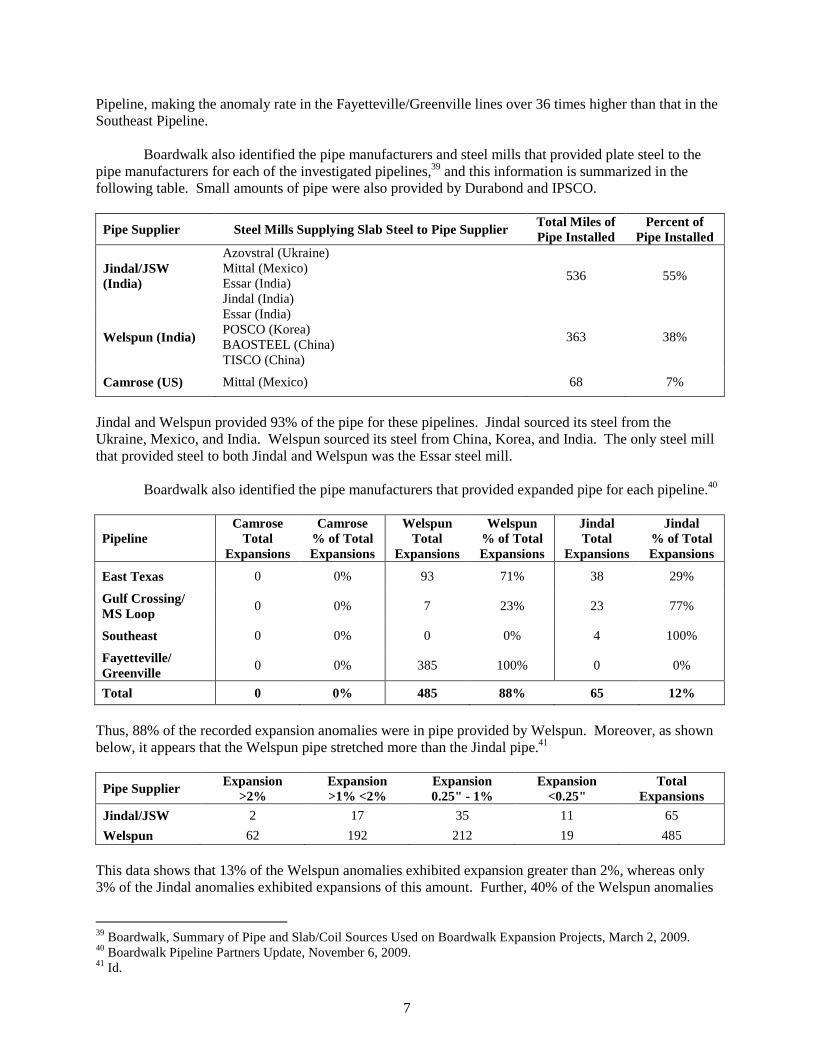
Boardwalk also identified the pipe manufacturers and steel mills that provided plate steel to the pipe manufacturers for each of the investigated pipelines,39 and this information is summarized in the following table. Small amounts of pipe were also provided by Durabond and IPSCO.
Pipe Supplier Steel Mills Supplying Slab Steel to Pipe Supplier Total Miles of Pipe Installed
Percent of Pipe Installed
Jindal/JSW (India)
Azovstral (Ukraine) Mittal (Mexico) Essar (India) Jindal (India)
536 55%
Welspun (India)
Essar (India) POSCO (Korea) BAOSTEEL (China) TISCO (China)
363 38%
Camrose (US) Mittal (Mexico) 68 7%
Jindal and Welspun provided 93% of the pipe for these pipelines. Jindal sourced its steel from the Ukraine, Mexico, and India. Welspun sourced its steel from China, Korea, and India. The only steel mill that provided steel to both Jindal and Welspun was the Essar steel mill.
Boardwalk also identified the pipe manufacturers that provided expanded pipe for each pipeline.40
Pipeline Camrose
Total Expansions
Camrose % of Total Expansions
Welspun Total
Expansions
Welspun % of Total Expansions
Jindal Total
Expansions
Jindal % of Total Expansions
East Texas 0 0% 93 71% 38 29%
Gulf Crossing/ MS Loop
0 0% 7 23% 23 77%
Southeast 0 0% 0 0% 4 100%
Fayetteville/ Greenville
0 0% 385 100% 0 0%
Total 0 0% 485 88% 65 12%
Thus, 88% of the recorded expansion anomalies were in pipe provided by Welspun. Moreover, as shown below, it appears that the Welspun pipe stretched more than the Jindal pipe.41
Pipe Supplier Expansion >2%
Expansion >1% <2%
Expansion 0.25" - 1%
Expansion <0.25"
Total Expansions
Jindal/JSW 2 17 35 11 65
Welspun 62 192 212 19 485
This data shows that 13% of the Welspun anomalies exhibited expansion greater than 2%, whereas only 3% of the Jindal anomalies exhibited expansions of this amount. Further, 40% of the Welspun anomalies
39 Boardwalk, Summary of Pipe and Slab/Coil Sources Used on Boardwalk Expansion Projects, March 2, 2009. 40 Boardwalk Pipeline Partners Update, November 6, 2009. 41 Id.

8
exhibited expansion of between 1% and 2%, whereas only 26% of the Jindal expansions were in this range. This data shows that Welspun pipe varies more in quality than Jindal pipe. Even though PHMSA did not provide any systematic analysis showing which steel mills provided the steel used in each defective pipe joint,42 it did provide some test data indicating that Boardwalk and PHMSA focused their testing efforts on steel provided by certain steel mills.43 The following table summarizes the number of tests performed on expanded pipe joints by pipe manufacturer and steel mill. Pipe Mill Tests on Welspun Pipe Tests on Jindal Pipe
Steel Mill
Ans
han
Bao
stee
l
Ess
ar
Mitt
al
PO
SC
O
TIS
CO
Wel
spun
T
otal
Azo
vsta
l
Mitt
al
Ess
ar
JSW
Jind
al
Tot
al
Pipelines
East Texas
Carthage to Hall Summit
2 2
4
Hall Summit to Vixen
2 4
6
Tullulah to Harrisville 2
69 2
73 1 6
7
Vixen to Tallulah
4 2
6
Gulf Crossing
Bennington to Paris
1
1
Mira to Sterlington
1 2
3
Paris to Mira
4 1 5 10
Sterlington to Tallulah
1 6 7
Mississippi Loop 3 3
6
Southeast 2 2 1
5
Fayetteville
Bald Knob to Lula
23
23
Grandville to Bald Knob
2 2
4
Greenville 7 5
12
Total Tests 2 9 99 2 1 6 119 15 26 2 5 48
For Welspun, 119 pipe joints were tested; for Jindal 48 pipe joints were tested. 42 It appears that PHMSA and Boardwalk determined that the defective steel could be traced to certain steel mills, because Boardwalk requested a variance from its Special Permit Modification Agreement for Welspun pipe manufactured with POSCO steel since only one pipe joint manufactured with POSCO steel had expanded. Letter, D. Goodwin, VP Boardwalk Pipeline Partners, to A. Mayberry, PHMSA, July 22, 2009. 43 Boardwalk Pipeline Partners Update, November 6, 2009.

9
The following table shows Boardwalk tested pipe made with Essar steel almost four times more than pipe made with steel from any other mill.
Steel Mill # Tests % of Tests Anshan 2 1% Azovstal 15 9% Baosteel 9 5% Essar 101 60% JSW 5 3% Mittal 28 17% POSCO 1 1% TISCO 6 4%
Total 167 100% This data shows that PHMSA and Boardwalk focused most of the strength testing on pipe produced by the Welspun-Essar combination. That there is a correlation between pipe expansions and pipe strength is shown by metallurgical test data for the Fayetteville/Greenville Pipelines provided by Boardwalk to PHMSA on October 7, 2009.44 This test data shows results for strength tests of 46 Welspun pipe joints, all of which were fabricated using steel from the Essar steel mill.45 Boardwalk strength tested 28 joints that had expanded more than 1.5%, 10 joints that had expanded approximately 1%, and eight joints that were “control joints” that showed no expansion. Each joint was subjected to nine separate tests.46 Almost all of the joints that had expanded more than 1.5% failed most of the strength tests. 47 The joints that expanded approximately 1% also failed most of the strength tests.48 In contrast, six of the eight control joints exceeded strength standards by substantial margins.49 The two control joints that did not pass all of the strength tests failed in only a few sample runs by narrow margins but generally passed almost all of the strength tests.50 This data shows a clear correlation between pipe expansions and the use of substandard steel. Even though it appears that PHMSA could order Boardwalk to trace each expansion anomaly to a specific steel mill, PHMSA did not provide such information in response to the FOIA Request. Further, the absence of a root-cause analysis in the information provided in response to the FOIA Request suggests that PHMSA did not conduct, report on, and/or disclose such analysis. Therefore, based on the documents provided by PHMSA it is not possible to determine the full extent of the low-strength steel problem or trace all possible low-strength steel from particular steel and pipe mills to particular pipelines. Tracing defective steel back to each steel mill is important because other PHMSA data suggests that one of the causes of the substandard steel was mis-formulation during alloying of the steel. In a September 8, 2009, report by the Microalloyed Steel Institute to PHMSA, the Institute determined that the pipe in the Fayetteville Pipeline (provided by Welspun) and Mississippi Loop Pipeline (provided by Jindal) had improper steel chemistry.51 The report noted low manganese levels and no vanadium, 44 Email, D. Goodwin, VP Boardwalk Pipeline Partners, to S. Nanney, PHMSA, October 7, 2009. 45 Id. 46 Id. Tests applied included flat strap yield, flat strap tensile, flat strap elongation, round bar yield, round bar tensile, round bar elongation, Charpy toughness, Charpy shear, and grain size tests. 47 Id. 48 Id. 49 Id. 50 Id. 51 Letter, J.M. Gray, Microalloyed Steel Institute, to S. Nanney, PHMSA, September 8, 2009.

10
niobium, and molybdenum in steel samples from the Mississippi Loop pipeline, and an absence of vanadium in the Fayetteville Pipeline.52 The data in Boardwalk’s November 6, 2009, Update also indicates that low strength pipe (including the switched slabs) had low levels of vanadium, niobium, and Titanium.53 In summary, it appears that 88% of the pipe that expanded was provided to Boardwalk by a single pipe manufacturer, Welspun, even though in terms of length it provided only 38% of the pipe for all the new Boardwalk pipelines combined. Welspun provided a total of 363 miles of pipe that contained 485 expansion anomalies, for a rate of over one anomaly per mile. In contrast, the Jindal pipe had an expansion anomaly rate of about one anomaly every eight miles, and pipe provided by Camrose exhibited no expansion anomalies at all. Also, the expansion anomalies found in the Welspun pipe were markedly worse than the anomalies in the Jindal pipe. Another difference is that Welspun and Jindal sourced their steel from different steel mills, except that they both acquired steel from the Essar steel mill. That Boardwalk and PHMSA focused their attention on pipes made by Welspun-Essar is also indicated by the fact that 60% of all tested pipe joints were made from steel produced by Essar. Further, it appears that mis-formulation of the steel alloy for this pipe may have been a cause of the weakness of some of the Welspun steel pipe. Ultimately, Boardwalk agreed to remove 305 pipe joints, including all pipe joints in the East Texas, Southeast, Gulf Crossing Pipelines that expanded more than 0.25” (148 pipe joints), and all pipe joints in the Greenville/Fayetteville Pipelines that expanded more than 1.5% (157 pipe joints).
Commodity Prices, Pipe Steel Market Growth and Quality Control
During the period when the defective pipe was fabricated, commodity prices soared, including prices for most metals. The following chart shows that the price for manganese more than tripled in 2007 and the price for iron ore and vanadium more than doubled in 2008.
This market evidence indicates that steel mills faced substantially higher prices for raw materials than they likely anticipated. It is reasonable to question whether these dramatic changes in commodity prices shifted steel mill priorities toward meeting production and price goals and away from quality control, including control over the quality of raw materials and steel formulation. However, in the absence of
52 Id. 53 Boardwalk Pipeline Partners Update, November 6, 2009.

11
systematic metallurgical analysis, it is not possible to know with certainty that a pattern of production of mis-alloyed steel existed, and that this was the root cause of the production of substandard pipe by manufacturers. During this same time period, demand for steel increased dramatically. According to the industry graph below, between 2007 and 2008 the miles of new pipe installed by the industry doubled.54
This increase in installed miles of pipe is reflected in a corresponding growth in sales of pipe by pipe mills. For example, from 2006 to 2009, Welspun increased its pipe production rapidly, registering nearly 50% increases in sales in fiscal years 2007 and 2008.55 Its pipe volume production rate increased by 34% in the third quarter of 2008 alone.56 This rapid growth likely required the retention and training of new employees, pressed steel and pipe mill infrastructure to its limits, and resulted in substantial management pressure on personnel to meet production deadlines. Such production conditions could have adversely impacted quality control.
PHMSA knew about quality control problems at a Jindal pipe mill as early as May 2007.57 Specifically, PHMSA conducted a visit of a Jindal mill to review quality control problems.58 PHMSA produced a list of concerns related to pipe rolling and coating, mill hydrotest equipment failures, seam inspection equipment failures, steel plate rejections, pipe end quality, pipe repair quality, pipe tracking, and oil and chloride contamination.59 Also, in September, 2007, Boardwalk was informed of allegations
54 Presentation, M. Hereth, INGAA Foundation, Best Practices in Procurement and Manufacturing Workshop, June 9, 2010, at 2. 55 KJMC Institutional Research, Reseach Updates, Welspun Gujarat Stahl Rohren Limited, June 3, 2009 and April 29, 2010. 56 Hindu Business Line, Welspun Gujarat Stahl Rohren: Buy, November 23, 2008. 57 Email, H. Wang, Boardwalk, to S. Nanney, PHMSA, June 25, 2007. 58 Id. 59 Id.

12
by two former Jindal pipe mill employees that Jindal’s production of steel for the East Texas Pipeline could impact the pipeline’s integrity.60 Although PHMSA provided no detail on these allegations, Gulf South, the initial developer of this pipeline, responded to them by conducting:
• a review of current inspection procedures, • a review of recordkeeping and data storage practices, • cross-checks on pipe data across multiple independent sources including:
Jindal, Gulf South, and third party suppliers for Jindal (double-joint contractors, NDE contractors),
• a physical audit of selected pipe with alleged issues, • a spot audit of inspection areas in question, and • immediate implementation of an independent tracking and verification
database for pipe procedures beyond the pipe mill to assure an independent check of pipe specification conformance, quality, and disposition through final shipment and receipt at Gulf South's field yards.61
Unfortunately, PHMSA provided very limited information about these early reports of pipe mill quality control problems. Nonetheless, the limited information provided indicates that the steel pipe industry was experiencing quality control challenges in 2007.
Summary of Industry Production and Use of Defective Steel Pipe The information provided by PHMSA in response to the FOIA Request is not as comprehensive
as expected. Nonetheless, it indicates that most pipe mills provide limited numbers of joints of substandard pipe, but in 2007 to 2009 the Welspun-Essar mill combination produced an unusually large amount of defective pipe, and that the Jindal-Mittal-Azovstal mill combinations also produced a significant amount of defective pipe.
Even though PHMSA did not provide data tracing the defective pipe steel to specific steel mills,
it appears that PHMSA, Kinder Morgan, and Boardwalk may very well have such data. In any case, the data provided by PHMSA shows that the problem here was not caused by random quality variation within the pipe manufacturing industry but rather the vast majority of the substandard steel provided to Boardwalk and Kinder Morgan can be attributed to the Welspun-Essar and Jindal-Mittal-Azovstal mill combinations.
The information provided by PHMSA also identifies that at least three distinct mechanisms are
believed to have caused the low-strength steel pipe provided to Boardwalk and Kinder Morgan: (1) improper steel chemistry; (2) improper rolling of steel plate; and (3) a lack of proper segregation of slabs of different grades of steel at steel mills. Other causes are possible. All of the identified mechanisms can result in violations of the API 5L X70 Standard and would impact the quality of large diameter X70 pipe regardless of the specific size. Also, market conditions during this time period may also have contributed to steel and pipe mill quality control failings. While the low-strength steel problem was first discovered after investigation of two failed hydrotests caused by low-strength steel pipe, hydrotesting did not identify the full scope of this problem. Only two of hundreds of defective pipe joints burst during the hydrotests. Instead, the scope of this
60 Emails, W. Bennett and J. Earley, Boardwalk, to S. Nanney et al., PHMSA, September 10-11, 2007. 61 Id.; Email, J. Garris, Boardwalk, to S. Nanney, PHMSA, September 24, 2007 (further describing Boardwalk’s response).

13
problem was identified only through high resolution caliper testing. Ultimately, PHMSA and the industry concluded that this problem was of sufficient gravity to require the removal and replacement of hundreds of pipe joints. Unfortunately, it does not appear that PHMSA has yet conducted a comprehensive root-cause analysis of this problem, given that it provided no such analysis in response to the FOIA Request. It also appears that PHMSA may not have conducted a comprehensive study of the possible flow of defective steel pipe from steel and pipe mills noted herein to new natural gas and hazardous liquid pipelines constructed in the U.S. from 2007 to 2009. Instead it appears that PHMSA limited its investigation to only Kinder Morgan and Boardwalk.
INDUSTRY TRADE ASSOCIATION RESPONSE PHMSA’s first formal action related to the defective pipe steel problem was to issue the Advisory Bulletin.62 In response, the industry convened a meeting on or about June 11, 2009, to which PHMSA was not invited.63 Apparently, one product of this meeting was a September 2009 White Paper by the Interstate Natural Gas Association of America Foundation (INGAA Foundation) entitled, “Identification of Pipe with Low and Variable Mechanical Properties in High Strength, Low Alloy Steels” (INGAA White Paper). By way of background to this issue, the INGAA White Paper states the following:
During 2007 and 2008 there was a significant increase in new pipeline construction in the United States. This construction boom put almost unprecedented demands on both pipe and other material manufacturers and pipeline constructors. To meet the demands for high yield line pipe, both traditional and newer pipe mills, utilizing plate and coil from both established and nontraditional steel suppliers, were used. During post-commissioning test (field hydrostatic test) inspection of some of these lines, a small number of pipe joints were detected that had expanded well beyond the dimensional tolerance limits of the pipe manufacturing specification, API Specification 5L. In most cases, the point at which this expansion occurred has not been definitively determined. As the investigation of this phenomenon progressed, it became apparent that it was not limited to one pipe mill, one steel supplier, or one manufacturing process. Through experience of a limited number of operators, it appeared that this issue was a rarity, affecting an extremely small percentage of pipe joints produced. However because the phenomenon could not be isolated or traced to a single source, PHMSA issued [the] Advisory Bulletin.64
Thus, due to a boom in pipeline construction, the industry admits that it acquired pipe from “newer,” and presumably less experienced pipe mills, and that some pipe mills acquired steel from “nontraditional” steel mills, which could be less familiar with the exacting quality control standards that regulate the construction of pipelines in the United States. It is reasonable to believe that unprecedented demands for high-strength steel pipe and high commodity costs increased the risk of production of substandard pipe in 2007 and 2008.
62 PHMSA Advisory Bulletin ABD-09-01, Potential Low and Variable Yield and Tensile Strength and Chemical Composition Properties in High Strength Line Pipe, 74 Fed. Reg. 23930, May 21, 2009. PHMSA also conducted a workshop on pipeline construction issues on April 23, 2009, which addressed a variety of pipeline construction failings. 63 Emails, P. Lidiak, API, to J. Wiese, PHMSA, May 21, 2009. 64 INGAA White Paper at 1.
Chris Peter
Highlight

14
Rather than seek or provide greater clarity about the cause and sources of the pipe joints that “expanded well beyond the dimensional limits of the pipe manufacturing specification, API Specification 5L,” the industry merely stated that the “point” of expansion (presumably this means time and cause of expansion) had not been “definitively determined.” It also stated that the expansions were not limited to one pipe mill, one steel mill, or one manufacturing process, thereby implying that problems linked to only a single supplier should be of concern (which makes no logical sense). It did not support its statements with any data. It also stated that industry operators believe that the quality control problems were a “rarity, affecting an extremely small percentage of pipe joints produced,” but failed to reference or provide any data supporting this statement or discuss the risks created by small amounts of defective pipe. After all, it only takes one bad pipe joint to create an environmental and economic disaster. In short, the INGAA White Paper ignored any detailed discussion of the root causes of the substandard pipe and offered only unfounded generalizations about the problem rather than solid explanations.
The industry attempted to justify a limited response to this problem by discussing historical pipeline failures occurring prior to the events that precipitated the Advisory Bulletin.65 Historical data is not relevant when current evidence suggests new types of industry failings in “unprecedented” market conditions. Historical data does not justify a lack of robust response by PHMSA or the industry to specifically identified problems.
Finally, the INGAA White Paper contains two flow charts intended to guide an operator of an
existing pipeline in its determination of whether it has a “potential issue with pipe quality and if so, what actions should be taken to address those issues.”66 Figure 1 indicates that existing pipelines intended to operate at an 80% design factor are subject to the review included in process B1.67 Figure 2 and its accompanying text describe the B1 process as being:
1) a determination of whether there is a known history of low mechanical properties or
excessive expansion found during normal operations;68 2) if such history exists, then a company should conduct an in-line inspection (ILI) during its
next assessment; and 3) if such investigation shows expansions greater than “X%” amount (X%” is not specifically
defined by the INGAA White Paper, which states only that it may be about 1%) then the company must “evaluate and mitigate” the expansions, apparently within one year of the analysis, however the industry has not identified what “evaluate and mitigate” means, when the one-year period tolls, or what actions might be required based on differing degrees of pipe failings.69
Thus, it appears that the industry recommends that operators of existing pipelines, including pipelines constructed between 2007 and 2009, conduct an inspection for expansion anomalies only if their “normal” review of pipe data or information discovered during normal operations indicates that a threat of expanded pipes exists. However, the INGAA White Paper makes no recommendations about the type of
65 INGAA White Paper at 2. 66 Id. at 3. 67 Id. 68 Id. The INGAA White Paper describes this history as, “Regardless of the preceding steps, if the company, through its normal review of the pipe data, such as is conducted during pipe production, and any other operational data or field observations, such as during tie-ins, installing taps, making coating repairs or performing pipe replacements, has made a determination that the threat of expanded pipe exists, then it must look further for such deformation during the next in-line inspection of the pipeline. If there is no evidence of low strength or excessively expanded pipe, no further action is required. Examples of such evidence include coating flaws caused by pipe strain and improper tie-in of a repair due to strain. This step does not contemplate extraordinary evaluations or inspections, but rather relies on those normally conducted as operations and maintenance activities.” 69 Id. at 6-9.
Chris Peter
Highlight
Chris Peter
Highlight

15
in-line inspection required, and it specifically states, “This step does not contemplate extraordinary evaluations or inspections, but rather relies on those normally conducted as operations and maintenance activities.”70 The INGAA Foundation’s recommendation is essentially to allow operators of pipelines constructed between 2007 and 2009 to determine by and for themselves whether or not they need to conduct high resolution deformation testing and how to redress any problems found. Its response provides no assurance of any systematic investigation of or response to the defective steel problem. Thus, it appears that the industry makes no recommendation that such operators do any initial investigation beyond normal operations and also does not recommend particular responses.
RECOMMENDED PHMSA ACTIONS
Since this report is based only on documents released pursuant to the FOIA Request, it is not possible to fully know about all of the actions taken by PHMSA in response to the defective steel problem. With this caveat in mind, we recommend that PHMSA take the following actions, if it has not already done so:
• Investigate and provide a public report on the use of defective steel in U.S. hazardous liquid and natural gas pipelines that:
o identifies the number of defective pipe joints discovered; o provides a description of each defective pipe joint; o provides any test results performed on each pipe joint; o indentifies the pipe and steel mill sources for each defective joint; o identifies the root cause or causes of the defective pipe joints; and o presents recommended improvements in safety regulations, safety enforcement, pipe steel
standards, pipeline testing, quality control surveillance, and other appropriate responses to this problem.
• Order all operators of natural gas and hazardous liquids pipelines constructed between 2007 and
2009 to conduct high-resolution in-line deformation caliper testing and provide the results of such inspections to the public on the PHMSA website;
• Order all operators of natural gas and hazardous liquids pipelines constructed between 2007 and
2009 using API 5L X70 and higher grades of pipe to trace pipe from pipe and steel mills with a history of supplying defective API 5L X70 and higher pipe to all U.S. pipelines that contain such pipe, regardless of pipe diameter, and provide a report to PHMSA and the public describing the use of such pipe in U.S. pipelines.
• Post all hydrotest results provided by pipeline operators on the PHMSA website; and
• Reduce the operating pressure of newly conducted hazardous liquid and natural gas pipelines to a
design factor of 72% or lower pending completion of PHMSA investigation of possible use of defective pipe steel, any necessary fitness for service determinations, and opportunity for public review and participation in these activities.
All of the foregoing recommendations include easily accessible information disclosures by PHMSA and greater opportunities for public participation in PHMSA activities. Greater transparency in PHMSA operations is necessary to ensure public participation in and support for PHMSA activities. A lack of transparency will result in a lack of trust and risk greater opposition to pipeline development.
70 Id. at 8.
Chris Peter
Highlight

16
The growing number of high-pressure, large diameter hazardous liquid and natural gas pipelines
are putting increasing numbers of citizens at risk. New large pipelines must be built to the highest standards and be fully tested using the best available technology to ensure that they comply with safety requirements. Existing pipelines, especially large diameter pipelines, must be tested with greater frequency as they age.
To avoid further fatalities, injuries, and property damage, PHMSA must adapt its safety
standards, regulations, and enforcement activities to protect citizens and their property from the greater risk posed by new large high-pressure pipelines. To gain greater public trust and public support for its activities, PHMSA must allow citizens to easily learn what it is doing and increase opportunities for citizens to participate in PHMSA’s efforts to protect them.

Enbridge Energy, Limited Partnership Department of State Application For Presidential Permit Exhibit C
Technical Specifications For
Border Crossing Facilities
Engineering data includes the following:
(a) Mileage, size of pipeline and interconnections;
The limited border crossing segment shall consist of approximately forty (40) feet
on each side of the International Boundary and shall be buried to a minimum
depth of three (3) feet below ground level; such segment shall connect at the
international boundary line with like facilities in the Province of Manitoba,
Canada.
(b) Specifications for pipe (diameter, length, wall thickness, grade) and valves (diameter and American National Standards Institute rating) with the maximum allowable operating pressure for each;
Pipe will be 36-inch outside diameter, 0.3750- to 0.469-inch wall thickness, API 5L
Grade X70, double submerged-arc (DSAW) steel pipe and manufactured in
accordance with Enbridge’s specifications EES103-2006 enclosed herewith as
Exhibit C.b.1. The maximum allowable operating pressure will be 1313 psig.
The valves to be installed will be 36-inch ANSI 600, weld end by weld end, full port,
rising stem gate valves. These valves will be manufactured in accordance with
API Standard 6D "API Specification for Steel, Gate, Plug, Ball and Check Valves
for Pipeline Service," and Enbridge specifications EES105-2006 enclosed herewith
as Exhibit C.b.2. The maximum allowable operating pressure of the valve will be
1440 psig.

Enbridge Energy, Limited Partnership Department of State Application For Presidential Permit Exhibit C
EXHIBIT C.b.1
Enbridge Specifications EES103-2006

Copyright ©© 2006 Enbridge Pipelines Inc. All rights reserved Engineering Equipment Specification – EES103 (2006)
Page 1 of 17
EES103 – 2006
Submerged-Arc-Welded Steel Pipe SpecificationSupplementary to API 5L
Revision: 0 Prepared By: Vincent Chou Approval Date: August 4, 2006

Copyright ©© 2006 Enbridge Pipelines Inc. All rights reserved Engineering Equipment Specification – EES103 (2006)
Page 2 of 17
1 Scope 1.1 PURPOSE AND COVERAGE 1.1.1 This Specification is prepared to be used in conjunction with API Specification 5L, Specification for Line Pipe, Forty-third Edition, March 2004, for the manufacture, qualification, inspection, and testing of submerged-arc welded steel line pipe for use in transportation of sweet service hydrocarbon fluids, and covers the requirements that are in addition to those specified in API 5L. All pipe shall meet the minimum requirements of API 5L, Forty-third Edition. In the event that conflict exists between this Specification and the requirements in API 5L, Forty-third Edition, the more stringent of the requirements shall apply. The numbering of clauses in this Specification corresponds, where possible, to that in API 5L, Forty-third Edition when the subject is covered in that specification, and any additional clauses are numbered sequentially. The requirements of the Appendices to this Specification shall also be met when applicable. 1.1.2
Pipe shall be supplied to meet the additional requirements outlined on the Specification Data Sheet(s) issued as applicable to each order, and on purchase order documentation applicable to each order. 1.2 PRODUCT SPECIFICATION LEVEL (PSL)
Pipe shall meet the level of technical requirements (product specification level) designated as PSL 2. 3 Definitions For the purposes of this Specification, the following additional definitions shall also apply: 3.9 manufacturer: a pipe manufacturer who proposes to, or has been contracted to provide to the purchaser, pipe manufactured to this Specification. 3.20 purchaser: that company, which is stated on the Specification Data Sheet(s) as purchaser, and shall include their engineering agencies, and other designated authorized representatives. 3.21 Specification Data Sheet(s): information issued to the prospective manufacturer in a format as outlined in Appendix B of this Specification, including information issued to the manufacturer on purchase order documentation or on any request-for-quotation documentation associated with a specific project. 3.22 crack: a stress-induced separation of the metal which, without any other influence, may be insufficient in extent to cause complete rupture of the material 3.23 single-jointer: two pieces of pipe welded together to make a length shorter than 50 ft. (15.2 m)

Copyright ©© 2006 Enbridge Pipelines Inc. All rights reserved Engineering Equipment Specification – EES103 (2006)
Page 3 of 17
3.24 double-jointer: two pieces of pipe welded together to make a length 50 ft. (15.2 m) or longer 3.25 triple-jointer: three pieces of pipe welded together to make a length 50 ft. (15.2 m) or longer 4 Information to be Supplied by the Purchaser 4.4 Specification Data Sheet(s) supplied for each order shall include applicable information outlined in Clauses 4.1, 4.2, and 4.3 of API 5L. It shall remain the responsibility of the manufacturer to clarify and submit as part of each specific quotation for supply, any proposed specific requirements of Clauses 4.1, 4.2, and 4.3 of API 5L not issued in the request for quotation. 5 Process of Manufacture and Material 5.1 PROCESS OF MANUFACTURE
Pipe furnished to this specification shall be submerged-arc welded as defined in Clauses 5.1.2.2.1, 5.1.3.5, and 5.1.3.11 of API 5L as applicable.
5.1.2 Welding Processes 5.1.2.3 Welding Procedure Qualification
Welding procedures for the longitudinal, helical, skelp end, and circumferential jointer welds, whichever are applicable, shall be qualified in accordance with the requirements of the latest edition of ASME Boiler and Pressure Vessel Code, Section IX for each welding process, and for each flux trade name/designation and electrode designation combination employed. 5.1.2.3.1
Material grade shall be included as an essential variable for qualification of welding procedures in accordance with ASME Boiler and Pressure Vessel Code, Section IX. 5.1.2.3.2 For pipe ordered with proven notch toughness properties, procedure qualification testing shall include Charpy V-notch impact tests of the weld and heat-affected zone. The absorbed energy requirements shall be as outlined on Specification Data Sheets. 5.1.2.3.3
Procedure qualification tests shall include at least three microhardness traverses across the weld, heat-affected zones, and parent material. One traverse shall be within 1/8” (3 mm) of the outside surface, one traverse shall be at the mid-wall point, and one traverse shall be within 1/8” (3 mm) of the inside surface. All readings in each zone shall be performed on the hardest-appearing structure. All hardness tests shall meet requirements outlined in clause 6.2.7 of this specification. 5.1.2.3.4
Utilization of pre-qualified welding procedures shall be permitted, if qualification documentation meets requirements of this Specification, and is submitted to the Purchaser and

Copyright ©© 2006 Enbridge Pipelines Inc. All rights reserved Engineering Equipment Specification – EES103 (2006)
Page 4 of 17
approved prior to start of production. Welding procedures qualified as part of production shall be documented and submitted to the Purchaser not later than seven days after the start of production. 5.1.5 Repair Welding
Defects in the longitudinal, helical , or circumferential seams, or in skelp end welds of submerged-arc welded pipe, shall be subjected to weld repair in accordance with requirements in Appendix B of API 5L. In addition to requirements outlined in B.3 of Appendix B of API 5L, the following requirements shall apply:
The maximum length of any repair shall be 10 in. (250 mm). The minimum distance of a repair weld from the pipe end shall be 12
in. (300 mm). The minimum distance between any two repaired weld locations shall
be 12 in. (300 mm). There shall not be more than 2 repairs in any 20 ft. (6 m) of weld. Back-to-back repairs shall not be permitted. Additional repair to a previously-repaired area shall not be permitted.
5.1.5.1 Repair Welding Procedure Qualification – Additional Tests
Repair welding procedure qualifications shall be carried out in accordance with requirements outlined in ASME Section IX, and in accordance with requirements outlined in Appendix C of API 5L.
Hardness tests shall be performed in general accordance with, and meet the requirements of Clause 6.2.7 of this specification.
For pipe ordered with proven notch toughness properties, repair welding procedure qualification tests shall include Charpy V-notch tests of the weld and heat affected zone. Energy absorption requirements and test temperature for notch toughness tests shall be as specified for pipe welds. 5.3 MATERIAL 5.3.3 Steel Deoxidation Practice
All pipe shall be made from killed steel. 5.3.4 Plate or Skelp Inspection
Coincident with submission of quotation, the Manufacturer shall provide details of procedures to be utilized for the ultrasonic inspection of skelp or pipe for the detection of laminar discontinuities in the steel. Acceptance criteria relating to defect size shall be included with the procedure, and shall be approved by the Purchaser prior to commencement of production. 5.7 Manufacturing Procedure Specification (MPS)
As part of the quotation for supply of line pipe under this Specification, the Manufacturer shall submit a Manufacturing Procedure Specification (MPS) providing the information including, but not limited to, that listed in Appendix A of this Specification. The Manufacturing Procedure Specification shall be approved by the Purchaser prior to commencement of

Copyright ©© 2006 Enbridge Pipelines Inc. All rights reserved Engineering Equipment Specification – EES103 (2006)
Page 5 of 17
production, and any subsequent changes to the Manufacturing Procedure Specification shall be approved by the Purchaser in writing prior to implementation.
6 Material Requirements 6.1 CHEMICAL PROPERTIES 6.1.1 Chemical Composition 6.1.1.1 Heat and Product Analysis
In addition to requirements outlined in API 5L, heat and product analysis shall conform to the requirements of Table 1 following:
Table 1
EElleemmeenntt SSyymmbbooll MMaaxxiimmuumm %% EElleemmeenntt
CCaarrbboonn CC 00..1133 MMaannggaanneessee MMnn **** PPhhoosspphhoorruuss PP 00..002200 SSuullpphhuurr SS 00..000088 SSiilliiccoonn SSii 00..4400 CCooppppeerr CCuu 00..4400 NNiicckkeell NNii 00..7700 CChhrroommiiuumm CCrr 00..3300 MMoollyybbddeennuumm MMoo 00..4400 NNiioobbiiuumm NNbb 00..1100 TTiittaanniiuumm TTii 00..003300 AAlluummiinnuumm ((ttoottaall)) AAll 00..1122 VVaannaaddiiuumm VV 00..0099 NNiittrrooggeenn NN **** ((NNiioobbiiuumm ++ VVaannaaddiiuumm )) ((NNbb ++ VV)) 00..1122 ((MMaannggaanneessee++CChhrroommiiuumm++MMoollyybbddeennuumm)) ((MMnn++CCrr++MMoo)) ****
**** lliimmiittaattiioonnss oonn ccoonnssttiittuueennttss MMnn,, ((MMnn++CCrr++MMoo)),, && NN::
CCaarrbboonn ((CC)) CCoonntteenntt
MMaannggaanneessee ((MMnn)) MMaaxxiimmuumm
((MMnn++CCrr++MMoo)) MMaaxxiimmuumm
NNiittrrooggeenn ((NN)) MMaaxxiimmuumm
≥≥..0099 11..7755 22..1155 00..001122 ..0088 11..8800 22..2200 00..001122 ..0077 11..9955 22..3355 00..001122 ..0066 11..9955 22..3355 00..001133 ..0055 22..0000 22..4400 00..001144 ≤≤..0044 22..0000 22..4400 00..001155

Copyright ©© 2006 Enbridge Pipelines Inc. All rights reserved Engineering Equipment Specification – EES103 (2006)
Page 6 of 17
6.1.3 Carbon Equivalent 6.1.3.2 Maximum Carbon Equivalent
For all pipe, the carbon equivalent shall not exceed CE (Pcm) of 0.22%, or CE(IIW) of 0.38%, whichever is applicable.
6.2 MECHANICAL PROPERTIES 6.2.1 Tensile Properties 6.2.1.1 Body Tensile Range
The range of actual yield strengths based on laboratory qualification testing shall not exceed 15,000 psi (104 MPa) for each pipe order of a specific diameter, wall thickness and grade. 6.2.1.2 Yield Ratio
The ratio of yield strength to ultimate tensile strength (Y/T ratio) shall not exceed .90. 6.2.5 Fracture Toughness Tests 6.2.5.3 Supplementary Fracture Toughness Tests 6.2.5.3.1 Supplementary Fracture Toughness Tests – Pipe Body
For pipe ordered with proven notch toughness properties, the following requirements shall apply:
(i) Pipe shall be tested to requirements of SR5, SR6, and SR19 of API 5L, Forty-
third Edition, as outlined on Specification Data Sheets. (ii) Pipe material shall exhibit an absorbed energy (full size equivalent) as outlined
in SR19, and also as outlined on Specification Data Sheets. (iii) Drop-weight tear tests shall exhibit a fracture shear area of 60% minimum for
any test, with no individual test specimen exhibiting less than 50% shear, except that for each order of a specific diameter, wall thickness and grade supplied using material from five or more heats of steel, the all-lot average shear area shall not be less than 85%. Shear area shall be reported for each individual Drop-weight Tear Test specimen.
6.2.5.4 Supplementary Fracture Toughness Tests - Weld Metal and Heat Affected Zones
For pipe ordered with proven notch toughness properties, longitudinal, helical, skelp end welds and circumferential mill welds, as well as heat affected zones, shall exhibit absorbed energies as outlined on the Specification Data Sheet(s). 6.2.7 Hardness Tests
Unless specified otherwise on the Specification Data Sheet(s), the hardness in the weld, heat affected zone and base metal shall not exceed 350 HV500, as determined using test methods in accordance with ASTM E384.
The results of all hardness tests shall be reported. 7 Dimensions, Weights, Lengths, Defects, and End Finishes

Copyright ©© 2006 Enbridge Pipelines Inc. All rights reserved Engineering Equipment Specification – EES103 (2006)
Page 7 of 17
7.2 DIAMETER
Tolerances for diameter of the pipe body and for diameter of the pipe ends shall be in accordance with requirements of Table 7 and Table 8 respectively of API 5L, except that the diameter tolerances shall not exceed minus 1/32” (0.8 mm) or plus 1/8” (3.2 mm) at any location along the length of the pipe.
7.2.1 Out-of-Roundness
For all pipe sizes and D/t ratios, the maximum difference between the lengths of the major and minor axes at any point along the pipe shall not exceed the lesser of 2% of the nominal outside diameter or 0.500” (12.7 mm). 7.3 WALL THICKNESS
The under-tolerance on wall thickness shall be 5% of the specified nominal wall thickness. 7.5 LENGTH
Length tolerances shall be as outlined on the Specification Data Sheet(s).
7.6 STRAIGHTNESS Deviation from a straight line shall not exceed 0.2% of the length, as applied along any
10 ft. (3 m) section of each pipe. 7.7 JOINTERS
It shall be acceptable to furnish mill jointers, subject to requirements of Appendix A of API 5L, and to requirements of this Specification.
7.7.1 Transverse Weld Tensile Tests – Jointer Welds
For circumferential mill jointer welds, tests shall be conducted at a frequency of one test per lot of 500 welds, and shall meet the ultimate tensile strength requirements of Table 3B of API 5L for the applicable grade of pipe.
7.7.2 Guided Bend Tests – Jointer Welds
For circumferential mill jointer welds, face and root guided-bend tests shall be conducted in accordance with Clause 9.10.3 of API 5L, at a frequency of one test per lot of 500 welds. 7.7.3 Single-jointers It shall be permissible to furnish single-jointers as defined in Clause 3.23 of this specification to a maximum of 5% of each order item. 7.7.4 Double-jointers It shall be permissible to furnish double-jointers as defined in Clause 3.24 of this specification for an entire order or any portion thereof. 7.7.5 Triple-jointers

Copyright ©© 2006 Enbridge Pipelines Inc. All rights reserved Engineering Equipment Specification – EES103 (2006)
Page 8 of 17
It shall be permissible to furnish triple-jointers as defined in Clause 3.25 of this specification to a maximum of 5% of each order item. 7.8 WORKMANSHIP AND DEFECTS 7.8.1 Dents
Plain dents deeper than ¼” (6.4 mm) and located in the pipe body, measured as the gap between the lowest point of the dent and a prolongation of the original contour of the pipe, or having a length in any direction exceeding one-half the pipe diameter, or both, shall be considered to be defects and shall be cut out as a cylinder.
All cold-formed dents deeper than 1/8 in. (3.2 mm) with a sharp bottom gouge shall be considered as defects, and shall be cut out as a cylinder or shall be removed by grinding.
Dents on welds shall not be permitted, and shall be cut out as a cylinder.
7.8.9 Cracks, Sweats, and Leaks All cracks, sweats and leaks shall be considered defects. Cracks as defined in this
Specification shall be considered to be defects regardless of dimensions, and shall be cut out as a cylinder.
7.8.14 Other Defects
Any imperfection on either of the external wall or internal wall surfaces of the pipe, and having a depth that results in a remaining wall thickness at any point of less than 95 per cent of the specified nominal wall thickness, shall be considered to be a defect. 7.8.14.1
Surface scores (sharp notches, gouges, scores, slivers, etc.) and all stress raising imperfections shall be removed by grinding even though they may be less than the maximum depth permissible for imperfections.
7.8.14.2 Pipe ordered to this Specification may be externally coated utilizing fusion bond epoxy or similar methods. Slivers, scabs, bristles or other surface imperfections that could result in an unacceptable applied coating shall be considered to be surface defects, and shall be removed by grinding or by other means acceptable to the purchaser. 7.8.15 Geometric Deviations
Geometric deviations from the normal cylindrical contour of the pipe which occur as a result of the pipe forming process or manufacturing operations (e.g. flat spots, peaks) shall not exceed 1/8” ( 3 mm), measured as the gap between the extreme point of the deviation and the prolongation of the normal contour of the pipe. 7.8.16 Grinding
The minimum remaining wall thickness at any point after grinding shall not be less than 95 per cent of the specified nominal wall thickness. 7.9 PIPE ENDS

Copyright ©© 2006 Enbridge Pipelines Inc. All rights reserved Engineering Equipment Specification – EES103 (2006)
Page 9 of 17
7.9.3 Plain Ends
Unless otherwise specified on Specification Data Sheet(s), the root face dimension shall be 1/16“ (1.6 mm) plus 1/32“ (0.8 mm) minus 0” (0.0 mm) for 95 per cent of the circumference of each pipe end.
Both ends of submerged-arc welded pipe shall have the inside weld reinforcement
removed for a minimum distance of 3” (75 mm) from the end of the pipe, such that the inside weld bead does not extend above the inside surface of the pipe by more than 0.020” (0.5 mm).
Where specified on Specification Data Sheet(s), both ends of submerged-arc-welded pipe
shall have the outside weld reinforcement removed for a distance of at least 5” (125 mm) from the end of the pipe, such that the outside weld bead does not extend above the outside surface of the pipe by more than 0.010” (0.25 mm) 9 Inspection and Testing 9.3.5 Fracture Toughness Tests 9.3.5.4 Charpy Testing Frequency – Welds
For pipe ordered with proven notch toughness properties, Charpy V-notch impact tests shall be conducted on the weld and heat affected zone of longitudinal, helical, skelp end welds and circumferential welds. For longitudinal, helical and skelp end welds, the test frequency shall be the same as that required for weld tensile tests in Table 13 of API 5L. For circumferential mill jointer welds, the test frequency shall be once per 500 welds completed.
9.3.6 Hardness Tests
Microhardness testing shall be performed at applicable frequencies as follows:
a) For longitudinal and helical welds: one test per welding day per O.D. welder, and at least once for each heat of material supplied for an order;
b) For skelp end welds: one test per lot of 100 lengths containing skelp end welds;
c) For circumferential mill welds: one test per lot of 500 welds.
Microhardness tests shall be performed in accordance with ASTM E384, at locations identical to those as outlined in clause 5.1.2.3.3 above, and shall meet requirements of Clause 6.2.7 of this Specification. 9.4 HYDROSTATIC TESTS 9.4.1 Hydrostatic Test Requirements
The pressure of the hydrostatic test medium shall stress the pipe wall to at least 95% of the specified minimum yield strength (SMYS). Test pressure shall be held constant for not less than 10 seconds.
9.4.2 Verification of Hydrostatic Test
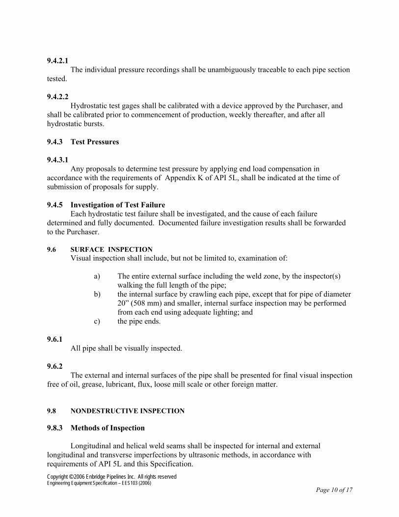
Copyright ©© 2006 Enbridge Pipelines Inc. All rights reserved Engineering Equipment Specification – EES103 (2006)
Page 10 of 17
9.4.2.1
The individual pressure recordings shall be unambiguously traceable to each pipe section tested. 9.4.2.2
Hydrostatic test gages shall be calibrated with a device approved by the Purchaser, and shall be calibrated prior to commencement of production, weekly thereafter, and after all hydrostatic bursts. 9.4.3 Test Pressures 9.4.3.1
Any proposals to determine test pressure by applying end load compensation in accordance with the requirements of Appendix K of API 5L, shall be indicated at the time of submission of proposals for supply. 9.4.5 Investigation of Test Failure
Each hydrostatic test failure shall be investigated, and the cause of each failure determined and fully documented. Documented failure investigation results shall be forwarded to the Purchaser. 9.6 SURFACE INSPECTION
Visual inspection shall include, but not be limited to, examination of: a) The entire external surface including the weld zone, by the inspector(s)
walking the full length of the pipe; b) the internal surface by crawling each pipe, except that for pipe of diameter
20” (508 mm) and smaller, internal surface inspection may be performed from each end using adequate lighting; and
c) the pipe ends. 9.6.1
All pipe shall be visually inspected. 9.6.2
The external and internal surfaces of the pipe shall be presented for final visual inspection free of oil, grease, lubricant, flux, loose mill scale or other foreign matter. 9.8 NONDESTRUCTIVE INSPECTION 9.8.3 Methods of Inspection
Longitudinal and helical weld seams shall be inspected for internal and external longitudinal and transverse imperfections by ultrasonic methods, in accordance with requirements of API 5L and this Specification.

Copyright ©© 2006 Enbridge Pipelines Inc. All rights reserved Engineering Equipment Specification – EES103 (2006)
Page 11 of 17
Skelp end welds shall be inspected for longitudinal and transverse imperfections by radiological methods in accordance with API 5L, by ultrasonic methods utilizing procedures approved by the Purchaser, or by a combination of radiological and ultrasonic methods. Fluoroscopic inspection shall not be accepted for specification compliance. Repair welds shall be inspected by radiological methods in accordance with Clause 9.8.4 of API 5L, except that fluoroscopic inspection shall not be accepted for specification compliance.
Circumferential jointer welds produced by double submerged arc welding shall be inspected for longitudinal and transverse imperfections by radiological methods in accordance with Clause 9.8.4 of API 5L, by ultrasonic methods in accordance with requirements of API 5L and this Specification, or by a combination of radiological and ultrasonic methods, except that fluoroscopic inspection shall not be accepted for specification compliance. Standards of acceptability for circumferential jointer welds shall be in accordance with the requirements of the latest edition of API 1104.
The junctions of jointer welds and other submerged-arc-welds shall be inspected by film
radiography or non-film radiological imaging techniques, or by ultrasonic inspection methods. Fluoroscopic inspection shall not be accepted for specification compliance. Standards of acceptability for the junctions of jointer welds and other submerged arc welds shall be in accordance with the requirements of Clause 9.8.4.6 of API 5L, or Clause 9.8.5.4 of this Specification, whichever is applicable, and shall also be in accordance with requirements of Clause 7.8.12 of API 5L.
The location of equipment in the manufacturer’s facility shall be such that all nondestructive inspection for compliance to specification requirements shall be performed after final hydrostatic testing. 9.8.3.3 Removal of Markings from Nondestructive Inspection
For all nondestructive inspection applied for specification and production control purposes, any paint markings applied to the pipe to mark locations where alarm limits were exceeded, or where imperfections were noted, shall be removed or painted over with black paint, as an indication that imperfections have been investigated for compliance to all requirements of this Specification. 9.8.3.4 Nondestructive Inspection Procedure Documentation
All nondestructive inspection procedures to be applied for specification compliance and for production control purposes shall be documented and submitted by the Manufacturer as part of the quotation for supply, and shall be approved by the Purchaser prior to implementation. 9.8.3.5 Additional Nondestructive Inspection of Pipe Ends
The finished bevel of all pipe ends shall be inspected for seams and laminations using an ultrasonic, liquid penetrant, or magnetic particle inspection method. Acceptance criteria shall be as outlined in Clause 7.8.10 of API 5L.

Copyright ©© 2006 Enbridge Pipelines Inc. All rights reserved Engineering Equipment Specification – EES103 (2006)
Page 12 of 17
9.8.5 Ultrasonic Inspection 9.8.5.2 Ultrasonic Inspection Reference Standards
Reference standards shall contain machined calibration reflectors as follows:
• 1/16” (1.6 mm) radially drilled hole, for application of acceptance limits and for setting of alarm levels applicable to longitudinal and transverse defect inspection;
• rectangular notches; ID and OD, longitudinal orientation, depth 5.0% of specified
wall thickness, dimensional tolerances as specified in Table 26 of API 5L, for the verification that the sound beam for longitudinal defect inspection is being directed perpendicular to the weld line
9.8.5.4 Acceptance Limits
For inspection of the pipe welds, imperfections that produce a signal greater than the applicable acceptance limit signal given in Table 23 of API 5L for the 1/16” (1.6 mm) radially drilled hole shall be considered defects, and shall be dispositioned in accordance with Clause 9.9 of API 5L.
9.8.7 Residual Magnetism Measurement Requirements
In addition to the requirements of Clause 9.8.7 of API 5L, the Manufacturer shall ensure that the measured flux density from residual magnetism induced into the pipe as a result of forming, welding, inspection, or any other aspect of the manufacturing process does not exceed 30 Gauss (3 mT). 9.12 RETESTS 9.12.7 Hardness Retests
In the event of a hardness test failure, a documented proposal for the location and number of retests shall be prepared by the Manufacturer and submitted for approval by the Purchaser. 9.14 RIGHT OF REJECTION
Where more than 50% of the pipe from any heat, heat treat lot or qualification lot is rejected due to a combination of defects in the steel, skelp or finished pipe, mechanical test failures, nondestructive inspection rejects or other deficiencies, the Purchaser reserves the right to reject all remaining pipe supplied from the affected lot. 10 Marking 10.1 GENERAL 10.1.3 Additional Markings and Method Of Application
The pipe number, length, and heat number (or code traceable to the heat number) shall be legibly stenciled on the inside of both ends of each pipe.
Any additional requirements for marking shall be outlined on the Specification Data Sheet(s). 12 Documents

Copyright ©© 2006 Enbridge Pipelines Inc. All rights reserved Engineering Equipment Specification – EES103 (2006)
Page 13 of 17
12.1 CERTIFICATION 12.1.2 PSL 2 Certification Requirements The Manufacturer shall, within seven days of completion of each mill run, supply material test certificates in a format approved by the Purchaser, and in accordance with requirements of this Specification.
12.1.2.1
Supply of material test certificates shall be a condition of acceptance and payment for pipe.
12.1.2.2
The reports and certificates shall provide information as specified in SR 15.1 of API 5L, and shall include the following additional information:
j) Tensile test results applicable to Y/T ratio and transverse weld
tensile tests, k) Qualification pipe number for each test; l) Deoxidation practice for steel;
m) Certification of hydrostatic test including duration and pressure; n) Certification of completion of guided bend tests;
o) Certification that nondestructive inspection was performed in accordance with, and met the requirements of this Specification and the approved Manufacturing Procedure Specification (MPS);
p) Certification correlating pipe number to heat number and plate number; and,
q) Certification that the pipe has been manufactured in accordance with the Manufacturing Procedure Specification (MPS), API 5L, and this Specification.
14 Purchaser Inspection
14.1
The provisions of Appendix H of API 5L shall apply. 14.2
The Manufacturer shall allow free access to the Purchaser to all steelmaking and rolling mill facilities providing skelp for the pipe order. 14.3
The Purchaser may arrange under separate contract with one or more third party agencies to conduct supervisory, visual, mechanical, electromagnetic, ultrasonic or other types of inspection in the pipe mill, rolling mill, or steel mill. The Manufacturer shall supply acceptable space to the Purchaser as may be necessary for the performance of this work. 14.4

Copyright ©© 2006 Enbridge Pipelines Inc. All rights reserved Engineering Equipment Specification – EES103 (2006)
Page 14 of 17
The Manufacturer shall permit access by the Purchaser to all specimens and test records applicable to specification-compliance testing and production control testing during the manufacture of steel, skelp and pipe.

Copyright ©© 2006 Enbridge Pipelines Inc. All rights reserved Engineering Equipment Specification – EES103 (2006)
Page 15 of 17
APPENDIX A – MANUFACTURING PROCEDURE SPECIFICATION REQUIREMENTS
The Manufacturing Procedure Specification submitted shall include, as a minimum, the following detailed information:
i) steel source, including steelmaking method, heat size, deoxidation practice, inclusion shape control practices, and casting method;
ii) aim chemistries and chemical limits for all elements referenced in Clause 6.1.1.1 of this Specification, and as applicable to pipe of each diameter, wall thickness and material grade to be made for the order;
iii) skelp rolling source, specific rolling and forming practices, including where applicable, typical reduction schedules, final finishing temperatures, and facilities for thermo-mechanical controlled rolling and on-line accelerated cooling;
iv) skelp inspection procedures; v) details of forming procedures; vi) pipe manufacturing location, and any plant limitations on wall thickness, diameter,
and material grade; vii) typical welding parameters and consumable combinations applicable to longitudinal,
helical, skelp end, repairs, and circumferential jointer welds; viii) a description of the quality organization applicable to steelmaking, casting, skelp
rolling and pipe manufacturing facilities, including identification of reporting practices, verification mechanisms to assure product traceability in accordance with requirements of SR 15.2 of API 5L, and responsibility for customer contact related to commercial and quality matters;
ix) a flow chart for pipe manufacturing, finishing, and qualification processes; x) normal mill control tolerances on all specification dimensions for pipe; xi) laboratory test equipment present at the manufacturing plant for testing of material
properties for the order; xii) all nondestructive inspection procedures utilized for specification compliance and for
production control, as applicable to skelp, pipe body, and welds xiii) method and typical amount of cold expansion as applicable; xiv) facilities available for external or internal coating in-house or by a third party; xv) yard handling, storage, and shipping procedures, including drawings of proposed
methods of stacking and securing pipe for shipment and method of end protection; and,
xvi) facilities available for the Purchaser or his representative.

Copyright ©© 2006 Enbridge Pipelines Inc. All rights reserved Engineering Equipment Specification – EES103 (2006)
Page 16 of 17
APPENDIX B SPECIFICATION DATA SHEET
SUBMERGED-ARC-WELDED STEEL PIPE
PPRROOJJEECCTT:: PPUURRCCHHAASSEERR:: AA.. PPIIPPEE RREEQQUUIIRREEMMEENNTTSS::
Item No. O.D. (in.)
W.T. (in.)
Grade Product Specification Level (PSL)
Pipe Test Temperature
(˚F)
Manufacturing Method
BB.. AAPPPPLLIICCAABBLLEE SSPPEECCIIFFIICCAATTIIOONNSS::
((ii)) AAPPII 55LL,, SSppeecciiffiiccaattiioonn ffoorr LLiinnee PPiippee,, 4433rrdd EEddiittiioonn (ii)
C. FLUID: Analysis attached D. MIN./MAX. OPERATING TEMPERATURE (°F)
EE.. MMAAXXIIMMUUMM FFIIEELLDD TTEESSTT PPRREESSSSUURREE::
FF.. FFIIEELLDD TTEESSTT MMEEDDIIUUMM::
GG.. FFIIEELLDD TTEESSTT DDUURRAATTIIOONN::
HH.. LLEENNGGTTHH RREEQQUUIIRREEMMEENNTTSS::
SSppeecciiffiieedd lleennggtthhss iinn eennttiirree sshhiippmmeenntt ((fftt..)) IItteemm ##
NNoommiinnaall LLeennggtthh ((fftt..)) MMiinniimmuumm aannyy
SSeeccttiioonn MMaaxxiimmuumm aannyy
SSeeccttiioonn MMiinniimmuumm aavveerraaggee
NNOOTTEESS::

Copyright ©© 2006 Enbridge Pipelines Inc. All rights reserved Engineering Equipment Specification – EES103 (2006)
Page 17 of 17
II.. SSUUPPPPLLEEMMEENNTTAARRYY RREEQQUUIIRREEMMEENNTTSS::
11.. PPIIPPEE BBOODDYY AABBSSOORRBBEEDD EENNEERRGGYY ((fftt--llbb))::
22.. PPIIPPEE BBOODDYY FFRRAACCTTUURREE AAPPPPEEAARRAANNCCEE ((%% SShheeaarr))
33.. WWEELLDD AABBSSOORRBBEEDD EENNEERRGGYY ((LLoonnggiittuuddiinnaall SSeeaamm)) ((fftt--llbb))::
44.. HHEEAATT AAFFFFEECCTTEEDD ZZOONNEE AABBSSOORRBBEEDD EENNEERRGGYY ((LLoonnggiittuuddiinnaall SSeeaamm))((fftt--llbb))::
55.. WWEELLDD AABBSSOORRBBEEDD EENNEERRGGYY ((HHeelliiccaall,, SSkkeellpp EEnndd,, CCiirrccuummffeerreennttiiaall WWeellddss)) ((fftt--llbb))::
66.. HHEEAATT AAFFFFEECCTTEEDD ZZOONNEE AABBSSOORRBBEEDD EENNEERRGGYY ((HHeelliiccaall,, SSkkeellpp--eenndd,, CCiirrccuummffeerreennttiiaall
WWeellddss)) ((fftt--llbb))::
77.. RREEQQUUIIRREEMMEENNTTSS FFOORR EENNDD PPRREEPPAARRAATTIIOONN::
88.. RREEQQUUIIRREEMMEENNTTSS FFOORR EEXXTTEERRNNAALL WWEELLDD FFLLUUSSHH--OOFFFF::
99.. MMAARRKKIINNGG RREEQQUUIIRREEMMEENNTTSS::
1100.. CCOOAATTIINNGG::
1111.. PPLLAANNTT IINNSSPPEECCTTIIOONN BBYY PPUURRCCHHAASSEERR::
1122.. OOTTHHEERR::
Initiated by: Date: Reviewed by: Date: Approved by: Date:

Enbridge Energy, Limited Partnership Department of State Application For Presidential Permit Exhibit C
EXHIBIT C.b.2
Enbridge Specifications EES105-2006

Steel Valve Specification EES105 - 2006
Version: 0 Issue Date: March 24, 2006 Prepared By: Jack Broyles Copyright © 2006 Enbridge Pipelines Inc., All Rights Reserved

VALVE SPECIFICATION EES105 – 2006
Copyright ©© 2006 Enbridge Pipelines Inc. All rights reserved Page i Engineering Equipment Specification – EES105 (2006)
Table of Contents 1 Scope ............................................................................................................................ 1
2 Intent ............................................................................................................................. 1
3 Terms, Definitions........................................................................................................ 1
4 Symbols and Abbreviations........................................................................................ 3
5 Valve Types .................................................................................................................. 4
6 Design ........................................................................................................................... 5
7 Materials...................................................................................................................... 11
8 Welding ....................................................................................................................... 15
9 Painting/Coating......................................................................................................... 16
10 Quality Control ........................................................................................................... 16
11 Pressure Testing ........................................................................................................ 19
12 Marking Requirements .............................................................................................. 23
13 Storage and Shipping ................................................................................................ 26
14 Documentation ........................................................................................................... 26
Appendix I Application Datasheet .................................................................................... 30
Appendix II Dimension Tables........................................................................................... 33
Appendix III CSA Z245.15 Alternatives (Canadian Installations) ................................... 44
Appendix IV Welded Ends ................................................................................................. 51
Appendix V Impact Testing Figures ................................................................................. 56

VALVE SPECIFICATION EES105 – 2006
Copyright ©© 2006 Enbridge Pipelines Inc. All rights reserved Page 1 Engineering Equipment Specification – EES105 (2006)
1 Scope
This Specification covers requirements for the manufacture, inspection, testing and shipment of gate, plug, ball and check valves intended for use in crude oil, petroleum product, and natural gas liquid pipeline systems. The pipeline systems are designed and constructed in accordance with:
Canada: i. National Energy Board, Onshore Pipeline Regulations
ii. CSA Z662 Oil and Gas Pipeline Systems
United States: i. Code of Federal Regulations, Title 49, Volume 3, Part 195 – Transportation of
Hazardous Liquids by Pipeline
ii. ASME B31.4 Pipeline Transportation Systems for Liquid Hydrocarbons and Other Liquids
This Specification covers valves in sizes from NPS 2 to NPS 60, inclusive.
Nominal pressure classes covered include:
Class Designation CSA ASME
PN 20 150 PN 50 300 PN 68 400
PN 100 600 PN 150 900
2 Intent
This specification embodies the required information of industry standards API 6D and CSA Z245.15 as well as Enbridge requirements.
The Application Datasheet shall be completed by the Owner or the Owner’s Engineer.
Any and all deviations from this specification shall be brought to the attention of the Owner in writing for resolution prior to final acceptance. All design documentation shall be submitted for approval in a retrievable and reproducible format.
3 Terms, Definitions
For the purposes of this specification, the following terms and definitions apply:
ANSI Rating Class: Numerical pressure design class defined in ASME B16.5 and used for reference purposes. NOTE: The ANSI rating class is designated by the word "Class" followed by a number.

VALVE SPECIFICATION EES105 – 2006
Copyright ©© 2006 Enbridge Pipelines Inc. All rights reserved Page 2 Engineering Equipment Specification – EES105 (2006)
Bi-Directional Valve: Valve designed for blocking the fluid in both downstream and upstream directions.
Bleed: Drain or vent.
Block Valve: Gate, plug or ball valve that blocks flow into the downstream conduit when in the closed position. NOTE: Valves are single- or double-seated, bi-directional or uni-directional.
Breakaway Thrust and Breakaway Torque: Thrust or torque required for opening a valve with maximum pressure differential.
By Agreement: Agreed between manufacturer and Enbridge purchaser.
Double-Block-and-Bleed (DBB) Valve: Valve with two seating surfaces, which, in the closed position, blocks flow from both valve ends when the cavity between the seating surfaces is vented through a bleed connection provided on the body cavity.
Drive Train: All parts of a valve drive between the operator and the obturator, including the obturator but excluding the operator.
Flow Coefficient: Kv – Volumetric flow rate, in cubic meters per hour, of water at a temperature between 5°C (40°F) and 40°C (104°F) passing through a valve and resulting in a pressure loss of 1 bar (14.7 psi). NOTE: Kv relates to the flow coefficient Cv in US gallons per minute at 15.6°C (60°F) resulting in a 1-psi pressure drop as follows:
Kv=Cv/1156
Full-Opening Valve: Valve that opens to the full diameter of the pipe to which it attached to allow unobstructed flow through the line.
Full Round Port Valve: Valve that opens to the full diameter of the pipe to which it attached to allow unobstructed flow through the line.
Handwheel: Wheel consisting of a rim connected to a hub, for example, by spokes, and used to operate manually a valve requiring multiple turns.
Locking Device: Part or an arrangement of parts for securing a valve in the open and/or closed position.
Manual Actuator: Manual Operator: Wrench (lever) or handwheel with or without a gearbox.
Maximum Pressure Differential (MPD): Maximum difference between the upstream and downstream pressure across the obturator at which the obturator may be operated.
Nominal Pipe Size (NPS): Numerical inches designation of size, which is common to components in piping systems of any one size. NOTE: the letters NPS followed by a number designates the nominal pipe size.
Nominal Pressure (PN) Class: Numerical pressure design class as defined in ISO 7005-1 and used for reference purposes. NOTE the nominal pressure (PN) class is designated by the abbreviation PN followed by a number.
Nominal Size (DN): Numerical metric designation of size, which is common to components in piping systems of any one size. NOTE: Nominal size is designated by the letters DN followed by a number.
Obturator / Closure Member: Part of a valve, such as a ball, clapper, disc, gate or plug, which is positioned in the flow stream to permit or block flow.

VALVE SPECIFICATION EES105 – 2006
Copyright ©© 2006 Enbridge Pipelines Inc. All rights reserved Page 3 Engineering Equipment Specification – EES105 (2006)
Operator: Device (or assembly) for opening or closing a valve.
Position Indicator: Device to show the position of the valve obturator.
Powered Actuator and Operator: Electric, hydraulic or pneumatic device bolted or otherwise attached to the valve for powered opening and closing of the valve.
Pressure Class: Numerical pressure design class expressed in accordance with either the nominal pressure (PN) class or the ANSI rating class. NOTE: In this Standard, the pressure class is stated by the PN class followed by the ANSI rating class between brackets.
Pressure-Containing Parts: Parts, such as bodies, bonnets, glands, stems, gaskets and bolting, designed to contain the pipeline fluid.
Pressure-Controlling Parts: Parts, such as seat and obturator, intended to block or permit the flow of fluids.
Process-Wetted Parts: Parts exposed directly to the pipeline fluid.
Reduced-Opening Valve: Valve with the opening through the obturator smaller than at the end connection(s).
Seating Surfaces: Contact surfaces of the obturator and seat, which ensure valve sealing.
Stem: Part that connects the obturator to the operator and which may consist of one or more components.
Stem Extension Assembly: Assembly consisting of the stem extension and the stem extension housing.
Support Ribs or Legs: Metal structure, which provides a stable footing when the valve is set on a fixed base.
Through-Conduit Valve: Valve with an unobstructed and continuous cylindrical opening.
Twin-Seat, Both Seats Bi-Directional, Valve: Valve with two seats, each sealing in both directions.
Twin-Seat, One Seat Uni-Directional And One Seat Bi-Directional, Valve: Valve with two seats, one sealing in one direction and the other in either direction.
Uni-Directional Valve: Valve designed for blocking the flow in one direction only.
Venturi Plug Valve: Valve with a substantially reduced opening through the plug and a smooth transition from each full-opening end to the reduced opening.
4 Symbols and Abbreviations
4.1 Symbols
Cv Flow coefficient in Imperial units.
Kv Flow coefficient in Metric units.
4.2 Abbreviations
BM Base Metal CE Carbon Equivalent

VALVE SPECIFICATION EES105 – 2006
Copyright ©© 2006 Enbridge Pipelines Inc. All rights reserved Page 4 Engineering Equipment Specification – EES105 (2006)
DBB Double-Block-and-Bleed DN Nominal Size HAZ Heat-Affected Zone HR Rockwell Hardness HV Vickers Hardness MPD Maximum Pressure Differential MT Magnetic-Particle Testing NDE Non-Destructive Examination NPS Nominal Pipe Size PN Nominal Pressure PQR Procedure Qualification Record PT Penetrant Testing PWHT Post-Weld Heat Treatment SMYS Specified Minimum Yield Strength WM Weld Metal WPS Weld Procedure Specification WQR Welder Qualification Record
5 Valve Types
5.1 Valve Types
Valves shall adhere to one of the following types and where applicable it shall also be designated either Full Port (FP) or Reduced Port (RP):
5.2 Gate Valves
Style 1: Single Slab Rising Stem
Style 2: Multi Piece Expanding Gate
Gate valves are to be used for fully opened or fully closed position only.
Multi piece gate valves shall be installed only in the up right position, and shall be used where temperature fluctuations may vary substantially beyond design atmospheric conditions.
Gate valves shall be provided with a back seat or secondary stem-sealing feature in addition to the primary stem seal.
Wedge gate valves shall have an internal wedge guide to prevent chatter and seat damage.
5.3 Plug Valves
Style 1: Non-Lubricated
Style 2: Lubricated

VALVE SPECIFICATION EES105 – 2006
Copyright ©© 2006 Enbridge Pipelines Inc. All rights reserved Page 5 Engineering Equipment Specification – EES105 (2006)
Plug valves shall have a cylindrical or conical obturator, which rotates about an axis perpendicular to the direction of flow.
Plug valves shall be short pattern type.
5.4 Ball Valves
Style 1: Top Entry Floating
Style 2: Three-Piece
Style 3: Welded Body
Ball valves shall have a spherical obturator, which rotates on an axis perpendicular to the direction of flow.
Ball valves 12” and larger shall be trunnion mounted.
5.5 Check Valves
Style 1: Reduced Opening Swing
Style 2: Full Opening Swing
Style 3: Dual Plate Wafer
Style 4: Single Plate Wafer
Check valves shall have an obturator, which responds automatically to block fluid in one direction.
5.6 Full-Opening Valves or Full Port Valves
Full-opening valves shall be unobstructed in the fully opened position and have an internal bore as specified in Table A1.1, Appendix I. There is no restriction on the upper limit of valve bore sizes.
Full-opening through-conduit valves shall have a circular bore in the obturator that will allow a sphere to pass. The bore diameter of the valve shall not be less than specified in Table A1.1, Appendix I.
Welding-end valves may require a smaller bore at the welding end to mate with the pipe.
5.7 Reduced-Opening Valves or Reduced Port Valves
The internal bore of reduced-opening or reduced port valves shall be less than the internal bore specified in Table A1.1, Appendix 1.
6 Design
6.1 Pressure and Temperature Rating
The nominal pressure (PN) class required is identified on the Application Datasheet.
Pressure classes shall be specified in accordance with the applicable rating tables for material groups in ASME B16.34.

VALVE SPECIFICATION EES105 – 2006
Copyright ©© 2006 Enbridge Pipelines Inc. All rights reserved Page 6 Engineering Equipment Specification – EES105 (2006)
The pressure and temperature ratings for metal (or equivalent) seats of ball valves, seated check valves shall be the same as for the flanges and shell.
The maximum operating pressure at the minimum and maximum operating temperatures shall be marked on the nameplate.
6.2 Sizes
All valves, except for reduced-opening valves, shall be furnished in the nominal sizes (DN) listed in Tables A1.2 to A1.6, Appendix I.
Reduced-opening valves shall be furnished in the nominal sizes in accordance with Table A1.1, Appendix I.
Reduced-opening valves with a circular opening through the obturator shall be specified by the nominal size of the end connections and the nominal size of the minimum bore of the obturator in accordance with Table A.1, Appendix I, except that for valve sizes DN 50 (NPS 2) or smaller the actual bore of the obturator shall be specified.
Reduced-opening valves with a non-circular opening through the obturator and reduced-opening check valves shall be designated as reduced-bore valves and specified by the nominal size corresponding to the end connections followed by the letter "R".
6.3 Face-to-Face and End-to-End Dimensions
Face-to-face and end-to-end dimensions of valves shall be in accordance with Tables A1.2 to A1.6, Appendix I.
The length of valves having one welding end and one flanged end shall be determined by adding half the length of a flanged-end valve to half the length of a welding-end valve.
Tolerances on the face-to-face and end-to-end dimensions shall be ± 2 mm for valve sizes DN 250 and smaller, and ±3 mm for valve sizes DN 300 and larger.
6.4 Minimum-Bore Full-Opening Valves
Minimum bores for full-opening valves shall not be less than those specified in Table A1.1, Appendix I.
6.5 Valve Operation
The maximum pressure differential (MPD) at which the valve is required to be opened by the lever, gearbox or actuator is indicated on the Application Datasheet.
The pressure rating as determined in accordance with Clause 6.1 for material at 38°C (100°F) shall be the MPD, unless otherwise specified.
6.6 Pigging
Valves that will be subjected to pigging shall be identified on the Application Datasheet.

VALVE SPECIFICATION EES105 – 2006
Copyright ©© 2006 Enbridge Pipelines Inc. All rights reserved Page 7 Engineering Equipment Specification – EES105 (2006)
6.7 Valve Ends
6.7.1 Flanged Ends
Standard end flanges shall be furnished with a raised face or ring joint faces (raised face or full face). Dimensions, tolerances and finishes, including drilling templates, flange facing, spot facing and back facing, shall be in accordance with:
a) ASME B16.5 Steel Pipe Flanges and Flanged Fittings (up to 24 inch).
b) ASME B16.47 Large Diameter Steel Flanges (formally MSS SP-44) (over 24 inch).
6.7.2 Welded Ends
Standard details for welded ends are illustrated in Appendix V.
Welding ends shall conform to Figures A5.1-1 and A5.1-2, Appendix V. In the case of a heavy-wall valve body, the outside profile may be tapered at 30° and then to 45° as illustrated in Figure A5.2, Appendix V.
The outside diameter, wall thickness, material grade, SMYS and special chemistry of the mating pipe, and whether cladding shall be specified in the Application Datasheet.
6.7.3 Special Flanges and Mechanical Joints
Special flanges and mechanical joints are not permitted.
6.8 Pressure Relief
The manufacturer shall determine whether fluid can become trapped in the body cavity in the open- and/or closed-valve position.
If fluid trapping is possible, then the manufacturer shall provide the valve with a means to prevent overpressure or a means to relief pressure such as automatic cavity pressure relief. The pressure relief line shall be connected to the non-isolated portion of the valve body. Relief to atmosphere is not acceptable.
Cavity relief, when required, shall prevent the pressure in the cavity from exceeding 1.33 times the valve pressure rating determined in accordance with Clause 6.1 for material at 38°C (100°F). External cavity relief valves shall be DN 15 (NPS 1/2) or larger.
6.9 Bypass and Drain Connections
Bypass or drain connections lines shall be identified on the Application Datasheet when required. Unless specified otherwise, bypass lines shall be 1/2” 304 Stainless steel tubing. Swagelok valves, tubing and fittings are preferred.
Valves for below grade service require drain lines to be routed to the top of the valve. For below grade valves, the bottom ½ in. NPT drain shall be piped to 450 mm (18 in.) above grade. The piping is to be capped with a ½ in. ball valve and plug.
Valves for above grade service shall be supplied with a removable drain plug. Drain plug threads shall be either tapered and capable of providing a pressure-tight seal or parallel-

VALVE SPECIFICATION EES105 – 2006
Copyright ©© 2006 Enbridge Pipelines Inc. All rights reserved Page 8 Engineering Equipment Specification – EES105 (2006)
threaded. Connections or plugs with parallel threads shall have a head section for trapping and retaining, a sealing member suitable for the specified valve service.
Thread forms shall be in accordance with ISO 228-1.
If specified on the Application Datasheet, the Vendor shall supply a double block and bleed port and valve for double seated valves. Bleed valves shall be of bolted or one-piece construction to guard against accidental disassembly.
6.10 Handwheels and Wrenches (Levers)
Wrenches for valves shall be an integral design or consist of a head, which fits on the stem and is designed to take an extended handle. The head design shall allow permanent attachment of the extended section if specified on the Application Datasheet.
The maximum force required at the handwheel or wrench to apply the breakaway torque or thrust shall not exceed 360 N (80 lbf). The manufacture shall provide a gear operator when this value is exceeded.
Wrenches shall not be longer than twice the face-to-face or end-to-end dimension of the valve.
Handwheel diameter shall not exceed the face-to-face or end-to-end length of the valve or 1000 mm, whichever is the smaller. Except for valve sizes DN 40 (NPS 1 1/2) and smaller, spokes shall not extend beyond the perimeter of the handwheel.
The handwheel of the gearbox input shaft shall be provided with a torque-limiting device, such as a shear pin, to prevent damage to the drive train.
The gear and motorized operators shall be designed to operate against the maximum differential pressure.
6.11 Position Indicators
Valves fitted with manual or powered actuators shall be furnished with a visible indicator to show the open and the closed position of the obturator.
For plug and ball valves, the wrench and/or the position indicator shall be in line with the pipeline when the valve is open and transverse when the valve is closed. The design shall be such that the component(s) of the indicator and/or wrench cannot be assembled to falsely indicate the valve position.
Valves without position stops shall have provision for the verification of open and close alignment with the operator/actuator removed.
6.11.1 Operators and Stem Extensions
6.11.2 Stem Extensions
Valves that require stem extensions will be indicated on the Application Datasheet with the length. The reference points for length shall be valve opening centreline to the face of the gear/activator mounting flange. Stems shall be constructed of one piece.
The Application Datasheet will indicate the dimension between centreline of the valve opening and the centreline of the handwheel. For electric motor operated valves, the valve Vendor shall

VALVE SPECIFICATION EES105 – 2006
Copyright ©© 2006 Enbridge Pipelines Inc. All rights reserved Page 9 Engineering Equipment Specification – EES105 (2006)
supply the dimensional details for review with the actuator vendor to ensure the desired extension dimensions are met.
Extended stem assemblies shall be strengthened as required to withstand the additional loading. All flanged, bolted, or machined surfaces on stem extensions shall have gaskets or have O-rings on mating surfaces to prevent water ingress into the valve stems.
The dimension of centreline of valve opening to top of grade (or platform) is specified on the Application Datasheet.
Extensions and valve yoke tubes shall be fitted with top and bottom ½ in. NPT drain fittings so that seals can be checked for leakage and water can be drained.
6.11.3 Misalignment
Misalignment or improper assembly of components shall be prevented by suitable means, such as a dowel pin or fitting bolt, which ensure the unique location of manual or powered operators and stem extension assemblies. Intermediate shaft guides shall be installed on extensions greater than 2500 mm (8 ft) in length.
6.11.4 Sealing
External connections shall be sealed, for example with gaskets or O-rings, to prevent external contaminants entering the mechanism.
6.11.5 Overpressure Protection
Operators and stem extension assemblies shall be provided with a means of preventing pressure build-up in the mechanism resulting from stem or bonnet seal leakage.
6.12 Valve Seat Lubrication
All valves shall be non-lubricated for normal valve seating.
Seat and/or stem sealant injection shall be provided when specified on the Application Datasheet. The valves shall be equipped with the provision for external lubricant injection to extend service life and provide emergency sealing, in case of worn seals. All grease fittings shall be “Flo-Wolf” or equal.
6.13 Lifting Lugs
Valves of size DN 200 (NPS 8) and larger shall be provided with lifting lugs.
6.14 Manual Actuator Provisions
The type of operator required is specified on the Application Datasheet.
Handwheel or wrench actuators shall have a maximum rim pull of 35 kg (80 lb). A clockwise rotation of the handwheel shall close the valve. An arrow indicating the direction of rotation to close the valve shall be permanently engraved on the handwheel.

VALVE SPECIFICATION EES105 – 2006
Copyright ©© 2006 Enbridge Pipelines Inc. All rights reserved Page 10 Engineering Equipment Specification – EES105 (2006)
6.15 Powered Actuator Provisions
Valves to be operated by powered actuators are specified on the Application Datasheet.
The interface between actuators and valve bonnet or stem extension assemblies shall be designed to prevent misalignment or improper assembly of the components. Fabrication drawings of the valve–actuator interface plate and stem connection details shall be provided with the valve at time of purchase.
Valves that are to be fitted with actuators by others shall be supplied with stem only and an actuator-mounting bracket installed.
The interface between actuators and valve bonnet or stem extension assemblies shall be sealed with gaskets or O-rings to prevent external contaminants from entering the assembly.
Means shall be provided of preventing pressure build-up in the actuator from stem or bonnet seal leakage.
The output of the actuator shall not exceed the maximum load capacity of the valve drive train.
Unless stated otherwise on the Application Datasheet, for electrically operated valves, the electric motor operator shall be supplied and installed by others.
6.16 Drive Trains
6.16.1 Design Thrust or Torque
The design thrust or torque for all drive train calculations shall be at least two times the breakaway thrust or torque.
Gears and bearings of the gearbox shall be weather, dust proof filled with suitable grease for -45ºC, and fully enclosed.
NOTE: This factor of safety is to allow for thrust or torque increase in service due to infrequent cycling, low-temperature operation and the adverse effect of debris.
6.16.2 Allowable Stresses
Tensile stresses in drive train components, including stem extensions, shall not exceed 67% of SMYS when delivering the design thrust or torque. The maximum design von Mises stress (combined bending, shear, torsion and bearing stresses) shall not exceed the 1/2 of the yield stress of the material for any component under any anticipated load.
A strength efficiency factor of 0.75 shall be used for fillet welds.
6.16.3 Allowable Deflections
For ball valves, the total torsional deflection of the extended drive train when delivering the design torque shall not exceed the overlap contact angle between the seat and obturator.
Deflections of the extended drive train shall not prevent the obturator from reaching the fully closed position.

VALVE SPECIFICATION EES105 – 2006
Copyright ©© 2006 Enbridge Pipelines Inc. All rights reserved Page 11 Engineering Equipment Specification – EES105 (2006)
6.17 Stem Retention
Valves shall be designed with a stem anti-blow-out device to prevent stem ejection by internal pressure when the stem packing and/or retainer has been removed.
7 Materials
The materials of construction shall include but not be limited to the following:
a) Valve body and pressure containment components;
b) Bonnet;
c) Shaft material;
d) Bolts and nuts;
e) Seals.
7.1 Material Specification
Materials of construction shall be as specified in this section. Manufacturers shall submit positive identification certificates in the form of a certified Material Test Report (MTR) for all pressure containing and process wetted components. The minimum information to be provided shall be:
a) Chemical properties;
b) Heat treatment;
c) Mechanical properties;
d) Test results;
e) Manufacturers Certification.
One or a combination of the following material specifications is anticipated for most applications (oil at typical Enbridge pipeline specifications). Alternate material may be proposed provided it is clearly identified by the manufacture and accepted by Enbridge and as required to meet the project specific requirements as indicated on the Application Datasheet. The temperatures shown are the minimum permitted per material specification, impact tested where applicable. For design temperatures below these values, impact testing for notch toughness is required.

VALVE SPECIFICATION EES105 – 2006
Copyright ©© 2006 Enbridge Pipelines Inc. All rights reserved Page 12 Engineering Equipment Specification – EES105 (2006)
Material Specification Product Form Minimum
Temperature ASTM A 216 Gr. WCB Carbon Steel casting -20 °F ASTM A 216 Gr. WCC Carbon Steel casting -20 °F ASTM A 217 Gr. WC6 ¼ Cr – ½ Mo casting -20 °F ASTM A 217 Gr. C5 5 Cr – ½ Mo casting -20 °F
ASTM A 217 Gr. WC9 2¼ Cr – ½ Mo
casting -20 °F
ASTM A 351 Gr. CF8M 18 Cr-10 Ni-2 Mo (alt.
Low temp.) -425 °F
ASTM A 352 Gr. LCB C-½ Mo casting -50 °F ASTM A 352 Gr. LCC C-½ Mo casting -50 °F
ASTM A105 Carbon Steel forging -20 °F ASTM A181 Cl. 60 Carbon Steel forging -20 °F ASTM A181 Cl. 70 Carbon Steel forging -20 °F ASTM A182 F11 ¼ Cr. - ½ Mo forging -20 °F ASTM A182 F22 2¼ Cr. - 1 Mo forging -20 °F ASTM A182 F6 13 Cr. Alloy forging -20 °F
ASTM A350 LF 2 Carbon steel forging -50 °F ASTM A537 Cl 1&2 Carbon steel plate -20 F ASTM A333 Gr. 6 Carbon steel pipe -50 F
Table 7.1 Material Specifications One or a combination of the following material specifications shall be used for valve trim material.
Trim Number Stem Body Seat Obturator Seat Back Seat
1 13% Cr. CS+13% Cr. CS+13% Cr 13% Cr 5 13% Cr CS+Stellite 6 CS+13% Cr 13% Cr 8 13% Cr CS+Stellite 6 CS+Stellite 6 18% Cr 12 SS316 CS+Stellite 6 CS+ SS 316 SS 316
Table 7.2 Trim Material Specifications
7.2 Gate and Globe Valves
Manufacturer may substitute ASTM A217 Gr. CA15 or A 351 Gr. CF8M material for wedge or globe base material.
For additional materials consult ASME B16.34 or Table 2 of CSA Z245.15, depending on location of installation. Alternate approved materials shall be noted on the Valve Datasheet completed by the manufacturer.

VALVE SPECIFICATION EES105 – 2006
Copyright ©© 2006 Enbridge Pipelines Inc. All rights reserved Page 13 Engineering Equipment Specification – EES105 (2006)
7.3 Gaskets and O-Rings
The metallic portion exposed to the service environment shall be of a material that has a corrosion resistance at least equal to that of the body material.
Inside diameter mating gaskets shall not be smaller than the inside diameter of the flanges.
Gasket or O-ring material shall have a duorometer number of 70 to 90. Acceptable materials, depending upon service conditions, are:
a) Kalrez® (-40° to 600° F);
b) Nitrile (Buna-N) (-40° to 275° F);
c) Highly Saturated Nitrile HSN (-40° to 350° F);
d) Viton® (Fluorocarbon) (-20° to 400° F);
e) Braided PTFE graphite.
Manufacturer shall confirm suitability of sealing material for service. Manufacturer shall also confirm suitability of sealing material for field hydrotesting with methanol and or glycol mixes.
7.4 Stem and Stem Nut
The stem shall be designed to accept the maximum torque required to open or close the valve under pressure without excessive deflection.
Stem material shall be selected per Clause 7.1. In certain applications, carbon steel stems with 3 mils of electroless nickel plating may be offered as an alternative, subject to the Company’s approval.
See also Clause 6.17.1 for torsion requirements.
Valve stem nuts used to engage gear drive mechanisms shall be of bronze or aluminium-bronze alloy material.
7.5 Valve Ends
Flanged valves shall have raised face flanges with dimensions and tolerances in accordance with the requirements of ASME B16.5 or MSS SP-44-1996.
Welded ends shall be beveled to accommodate a butt weld connection to pipe in accordance with the manufacturing specification. The specifics of the matching pipe are provided on the Application Datasheet.
The Vendor shall indicate whether pipe transition pieces would be required to accommodate the butt weld to the matching pipe. Valves ends made of cast materials shall have transition pieces supplied and installed by the Vendor to accommodate the butt weld to matching pipe.
In some cases, the Company will require transition pieces and will specify this on the Application Datasheet. If transition pieces are required, the Company and Vendor shall agree on the supply of materials and the design of the end connection.

VALVE SPECIFICATION EES105 – 2006
Copyright ©© 2006 Enbridge Pipelines Inc. All rights reserved Page 14 Engineering Equipment Specification – EES105 (2006)
7.6 Service Compatibility
All process-wetted parts, metallic and non-metallic, and lubricants shall be suitable for the commissioning fluids and service specified by on the Application Datasheet.
The description and properties of the fluid handled, including minimum and maximum temperature, specific gravity, viscosity, etc shall be provided to the manufacturer prior to valve fabrication.
The manufacturer shall consider all of the data in the Valve Datasheet when selecting the appropriate materials of manufacture for the valve. Asbestos and asbestos compounds shall not be used.
7.7 Forged Parts
Forged pressure containing parts shall be forged close to the finished shape and size.
7.8 Welding Ends
7.8.1 For Welded End Valves
The chemistry of carbon steel welding ends shall meet the following requirements:
a) The carbon content shall not exceed 0.23% by mass in the ladle (heat) analysis or 0.25% by mass in the product (check) analysis;
b) The maximum content of both sulfur and phosphorus shall not exceed 0.035% by mass;
c) The carbon equivalent (CE) shall not exceed 0.43 in the ladle (heat) analysis or 0.45 in the product (check) analysis. The CE shall be calculated in accordance with the following formula:
CE = %C + (% Mn/6) + (% Cr + % Mo + % V)/5 + (% Ni + % Cu)/15
The chemistry of austenitic stainless steels for welding ends shall meet the following requirements:
a) The carbon content shall not exceed 0.03% by mass, except under the conditions outlined in b) and c) below;
b) A carbon content of up to 0.08% by mass is permissible provided the material is stabilized with niobium and the niobium content is at least 10 times the carbon content by mass;
c) For steels stabilized with niobium or tantalum, the combined mass of niobium and tantalum shall be at least eight times the mass of the carbon. Requirements for the chemistry of welding ends made of other materials shall be established by agreement.
7.9 Toughness Test Requirements – Materials
Manufacturer to provide the results of impact testing when the minimum service temperature is below -29°C.
All carbon and low-alloy steels for pressure-containing parts in valves with a specified design temperature below -29°C (-20°F) shall be impact-tested using the Charpy V-notch technique in accordance with ISO 148 or ASTM A 370.

VALVE SPECIFICATION EES105 – 2006
Copyright ©© 2006 Enbridge Pipelines Inc. All rights reserved Page 15 Engineering Equipment Specification – EES105 (2006)
Materials shall be procured to documented specifications.
Toughness testing may be performed during the qualification of the valve manufacturing procedure provided that the material for testing is heat-treated using the same equipment as during valve production.
The impact test temperature shall be as defined in the Application Datasheet for minimum temperature.
Except for material for bolting, impact test results for full-size specimens shall meet the requirements of Table 7.3 Impact test results for bolting material shall meet the requirements of ASTM A 320.
Average of Three Specimens (MPa)
Average of Three Specimens (J)
Minimum for Single Specimen (J)
≤ 586 20 16 587 - 688 27 20 ≥ 689 34 25
Table 7.3 Charpy V-Notch Impact Requirements (Full-Size Specimen)
7.10 Bolting
Bolting shall be suitable for the specified valve service and pressure rating.
ASTM Specifications:
a) Bolts A 193 Gr. B7, or A 320 Gr. L7 (low temp)
b) Nuts A 194 Gr. 2H, or A 194 Gr. 4 (low temp)
8 Welding
8.1 Qualifications
Welding, including repair welding, of pressure - containing and pressure-controlling parts shall be performed in accordance with procedures qualified to ASME Section IX or EN 288-3, and Clauses 9.2 and 9.3 of this specification. Welders and welding operators shall be qualified in accordance with ASME Section IX or EN 287-1.
The Vendor shall notify the Company when a repair has been made to a valve.
The manufacturer shall provide an adequate quality control of welding and welding repair.
The results of all qualification tests shall be documented in a procedure qualification record (PQR). Post-weld heat treatment (PWHT) shall be performed in accordance with the relevant material specification.
8.2 Impact Testing – Welding
Impact testing shall be carried out for the qualification of procedures for welding on valves with a design temperature below -29°C (-20°F). Where required impact testing temperature shall be -45°C, lower temperatures may be specified on the Application Datasheet.

VALVE SPECIFICATION EES105 – 2006
Copyright ©© 2006 Enbridge Pipelines Inc. All rights reserved Page 16 Engineering Equipment Specification – EES105 (2006)
NOTE: Design code and/or local requirements may require impact testing at minimum design temperatures above -29°C (-20°F).
A set of three weld metal impact specimens shall be taken from the weld metal (WM) at the location shown in Figure A6.3, Appendix IV. The specimens shall be oriented with the notch perpendicular to the surface of the material.
A set of three impact specimens shall be taken from the heat-affected zone (HAZ) at the location shown in Figure A6.4, Appendix IV. The notch shall be placed perpendicularly to the material surface at a location resulting in a maximum amount of HAZ material located in the resulting fracture.
HAZ tests shall be conducted for each of the materials being joined when the base materials being joined are of a different P-number and/or group number in accordance with ASME Section IX or when one or both of the base materials being joined are not listed in the P-number grouping.
Impact testing shall be performed in accordance with ISO 148 or ASTM A 370 using the Charpy V-notch technique. Specimens shall be etched to determine the location of the notch.
The impact test temperature for welds and heat-affected zones shall be at or below the minimum design temperature specified for the valve.
Impact test results for full-size specimens shall meet the requirements of Table 7.3, Hardness testing. Hardness surveys shall be performed on base metal (BM), WM and HAZ as indicated in Appendix IV using the Rockwell HRC or Vickers HV10 method.
9 Painting/Coating
9.1 Coating
Valves for below grade service shall be coated. Vendor shall provide the coating procedure with his bid submission for approval by Enbridge. If the procedure is not approved, then the vendor shall coat the valve using Enbridge’s “C-110 Coating of Buried Steel with Plural Component Spray Applied Coatings” procedure.
9.2 Painting
Valves for above grade service shall be painted. The Vendor shall provide the painting procedure with his bid submission for Enbridge approval. If the procedure is not approved, then the Vendor shall paint the valve using Enbridge’s “P-210 Shop and Field Painting” procedure.
10 Quality Control
10.1 Non-Destructive Testing
Manufacturers that are certified holders of a current API Monogram license, supplying monogrammed product need only submit a copy of the license, and contact name of the responsible shop inspector.
All other Manufacturers shall supply a copy of their Quality Test plan verifying NDE requirements are met and that they are in accordance with the material specification for review and acceptance. Non-Destructive testing shall be conducted to the extent necessary to detect

VALVE SPECIFICATION EES105 – 2006
Copyright ©© 2006 Enbridge Pipelines Inc. All rights reserved Page 17 Engineering Equipment Specification – EES105 (2006)
all defects in the manufactured piece or pieces and to determine compliance with dimensional requirements. The Manufacturer shall clearly indicate which procedures (Radiographic, Ultrasonic, Magnetic particle, Liquid Penetrant) are used and to what extent. Acceptable procedures are given in Table 10.1 below.
One or several of the follow methods shall be utilized for Non Destructive testing of the valve components:
Manufactured Component Examination Exam Procedure Acceptance Criteria
Radiographic ASME V, Article 22
ASME VIII, Div. 1 Part UW51 for linear indications and Appendix 4 for rounded indications
Weldments – all pressure boundary welds require 100%
examination Ultrasonic ASME V, Article 23 ASME VIII, Div. 1,
Appendix 12
Castings Radiographic ASME V, Article 22 ASME VIII, Div. 1, Appendix 7
Castings Ultrasonic ASME V, Article 23 ASTM A 609, Table 2, Quality Level 1
Castings Magnetic Particle ASME V, Article 25 ASME VIII, Div. 1, Appendix 6
Castings Liquid Penetrant ASME V, Article 24 ASME VIII, Div. 1, Appendix 8
Forgings Ultrasonic ASTM A 388 ASTM A 388
Forgings Magnetic Particle ASME V, Article 25 ASME VIII, Div. 1, Appendix 6
Plates (as applicable) Ultrasonic ASTM A 435 or A 577 ASTM A 435 or A 577
Table 10.1 Non Destructive Testing Requirements
10.2 Non-Destructive Test Records
All radiographs shall be identified and shall be available for the Company representative to view. A written record of all non-destructive examinations required by this Specification and the results shall be submitted to the Company upon completion of the order.
10.3 Measuring and Test Equipment
10.3.1 General
Equipment used to inspect, test or examine material or equipment shall be identified, controlled and calibrated at intervals specified in the manufacturer's instructions.
10.3.2 Dimension-Measuring Equipment
Equipment for measuring dimensions shall be controlled and calibrated in accordance with methods specified in documented procedures.

VALVE SPECIFICATION EES105 – 2006
Copyright ©© 2006 Enbridge Pipelines Inc. All rights reserved Page 18 Engineering Equipment Specification – EES105 (2006)
10.3.3 Pressure-Measuring Devices
10.3.4 Type and Accuracy
Test pressure measuring devices shall be either pressure gauges or pressure transducers, which are accurate to within ± 2.0% of the full-scale reading.
10.3.5 Gauge Range
Pressure measurements shall be made between 25% and 75% of the full pressure range of the measuring device.
10.3.6 Calibration Procedure
Pressure-measuring devices shall be periodically recalibrated with a master pressure-measuring device or a deadweight tester at 25%, 50%, 75% and 100% of the full pressure scale.
10.3.7 Temperature-Measuring Devices
Devices for measuring temperature, if required, shall be capable of indicating and recording temperature fluctuations of 3°C (5°F).
10.4 Qualification of Inspection and Test Personnel
10.4.1 NDE Personnel
NDE personnel shall be qualified in accordance with the requirements specified in ASNT SNT-TC-1A or EN 473 Level II as a minimum.
Personnel performing visual examinations shall have passed an annual eye examination in accordance with ASNT SNT-TC-1A or EN 473 within the previous twelve months.
10.4.2 Welding Inspectors
Personnel performing visual inspection of welding operations and completed welds shall be qualified and certified to the requirements of AWS QC1, or equivalent, or a manufacturer's documented training program.
10.5 NDE of Repair Welding
After defect removal, the excavated area shall be examined by magnetic particle (MT) or liquid penetrant (PT) methods prior to starting repair welding.
Repair welds on pressure-containing parts shall be examined using MT or PT methods. Acceptance criteria shall be specified in documented procedures.
10.6 Shop Inspection
The Company may have a Company Inspector present in the Vendor’s manufacturing facility at any time during the manufacture of the valves. The Company Inspector may witness all

VALVE SPECIFICATION EES105 – 2006
Copyright ©© 2006 Enbridge Pipelines Inc. All rights reserved Page 19 Engineering Equipment Specification – EES105 (2006)
hydrostatic tests and may be present for other tests and NDE. The Company Inspector may also witness the final inspection of each valve prior to shipment to ensure the valves meet all requirements of this Specification and the purchase order.
The Company shall be notified of any injurious defects found on any pressure containing valve component during non-destructive tests.
11 Pressure Testing
11.1 General
Each valve shall be tested in accordance with this clause prior to shipment. Testing shall be performed in the sequence used in this clause for specifying the test requirements. Shell pressure testing shall be carried out before painting of the valves. Test fluids shall be fresh water, which may contain corrosion inhibitors. The chloride content of test water for austenitic and ferritic-austenitic (duplex) stainless-steel body/bonnet valves shall not exceed 30 ppm.
Valves shall be tested with the seating and sealing surfaces free from sealant except where the sealant is the primary means of sealing.
Tests specified with the valve half-open may also be performed with the valve fully open provided the body cavity is simultaneously filled and pressurized through a cavity connection.
Methods for monitoring pressures and/or leakage shall be adequate also when valve body connections are not available for direct monitoring. The leak test shall be performed at both the minimum and maximum operating temperatures. A sufficient stabilization period shall be allowed for all pressure tests. Test shall be witnessed by Enbridge or designate. Pressure testing shall be performed in accordance with documented procedures.
11.2 Stem Backseat Test
Stem backseat testing shall be performed prior to shell testing. Where a valve has a stem backseat feature, testing of the backseat shall commence with the seat free. Self-energized packing or seals shall be removed unless a test port is provided for this test.
The valves shall be filled with the ends closed off and the obturator in the partially open position until leakage of the test fluid around the stem is observed. The backseat shall then be closed and a minimum pressure of 1.1 times the pressure rating determined in accordance with Clause 6.1 for material at 38°C (100°F) is applied for the duration specified in Table 11.1.
Monitoring for leakage shall be through a test access port or by monitoring leakage around the loosened packing.
No visible leakage is permitted at this test pressure.
Valve Size
DN (mm)
NPS (inches)
Test Duration (minutes)
≤ 00 ≤ 4 2
≥ 50 ≥ 6 5
Table 11.1 Minimum Duration of Stem Backseat Tests

VALVE SPECIFICATION EES105 – 2006
Copyright ©© 2006 Enbridge Pipelines Inc. All rights reserved Page 20 Engineering Equipment Specification – EES105 (2006)
11.3 Hydrostatic Shell Test
Hydrostatic shell testing shall be performed on the fully assembled valve prior to painting or coating.
Valves shall be closed off and the obturator placed in the partially open position during the test. The method of closing the ends shall permit the transmission of the full-pressure force acting on the end blanks to the valve body. Where present, external relief valves shall be removed and their connections plugged.
The test pressure shall be 1.5 or more times the pressure rating determined in accordance with Clause 6.1 for material at 38°C (100°F). The duration shall not be less than that specified in Table 10.2.
Where the longer test durations are required, these will be indicated on the Application Datasheet.
Valve Size
DN (mm)
NPS (inches)
Test Duration (minutes)
15 -100 ½ - 4 2 150 -250 6 -10 5 300 -450 12 -18 15 500 - 915 20 - 36 30
Over 915 > 36 120
Table 11.2 Minimum Duration of Hydrostatic Shell Tests
The test shall be documented on a chart recorder.
No visible leakage is permitted during the hydrostatic shell test.
After hydrostatic shell testing, external relief valves shall be (re)fitted to the valve. The connection to the valve body shall be tested at 95% of the set pressure of the relief valve for 2 minutes for valve sizes up to and including DN 100 (NPS 4), and 5 minutes for valve sizes DN 150 (NPS 6) and larger. The relief valve connection shall be free of visible-leakage during this period.
Where provided, the external relief valve shall be set to relieve at the specified pressure and tested. The set pressure of relief valves shall be between 1.1 and 1.33 times the valve pressure rating determined in accordance with Clause 6.1 for material at 38°C (100°F).
11.4 Hydrostatic Seat Test
11.4.1 Preparation
Lubricants shall be removed from seats and obturator sealing surfaces except, by agreement, for assembly lubricants for metal-to-metal contact surfaces.

VALVE SPECIFICATION EES105 – 2006
Copyright ©© 2006 Enbridge Pipelines Inc. All rights reserved Page 21 Engineering Equipment Specification – EES105 (2006)
11.4.2 Test Pressure and Duration
The test pressure for all seat tests shall not be less than 1.1 times the pressure rating determined in accordance with Clause 6.1 for material at 38°C (100°F). The test duration shall be in accordance with Table 11.3.
When longer test durations are required, these will be indicated on the Application Datasheet.
Valve Size
DN (mm)
NPS (inches)
Test Duration (minutes)
15 -100 ½ - 4 2 150 - 915 6 - 36 5
Over 915 > 36 10
Table 11.3 Minimum Duration of Seat Tests
The test shall be documented on a chart recorder.
11.4.3 Acceptance Criteria
Leakage for soft-seated valves and lubricated plug valves shall not exceed ISO 5208 Rate A (no visible leakage). For metal-seated valves the leakage rate shall not exceed ISO 5208 Rate D, except that the leakage rate during the seat test in Clause 11.4.4.5.2 shall not be more than two times ISO 5208 Rate. The test procedures for various types of block valve are given in Clause 11.4.4.
11.4.4 Test Procedures for Block Valves
11.4.5 Uni-Directional
With the valve half-open, the valve and its cavity shall be completely filled with test fluid. The valve shall then be closed and the test pressure applied to the appropriate end of the valve.
Leakage from each seat shall be monitored via the valve body cavity vent or drain connection. For valves without a body cavity connection, seat leakage shall be monitored from each seat at the respective downstream end of the valve (the valve end downstream of the pressurized test fluid).
11.4.6 Bi-Directional
With the valve half-open, the valve and its cavity shall be completely filled with test fluid. The valve shall then be closed and the test pressure applied successively to both ends of the valve.
Seat leakage shall be monitored from each seat via the valve body cavity vent or drain connection. For valves without a body cavity vent or drain connection, seat leakage shall be monitored from the respective downstream end of the valve.

VALVE SPECIFICATION EES105 – 2006
Copyright ©© 2006 Enbridge Pipelines Inc. All rights reserved Page 22 Engineering Equipment Specification – EES105 (2006)
11.4.7 Twin-Seat, Both Seats Bi-Directional
Each seat shall be tested in both directions.
Cavity relief valves shall be removed if fitted. The valve and cavity shall be filled with test fluid, with the valve half-open, until the test fluid overflows through the cavity relief connection.
To test for seat leakage in the direction of the cavity, the valve shall be closed. The test pressure shall be applied successively to each valve end to test each seat separately from the upstream side. Leakage shall be monitored via the valve cavity pressure relief connection.
Thereafter, each seat shall be tested as a downstream seat. Both ends of the valve shall be drained and the valve cavity filled with test fluid. Pressure shall then be applied whilst monitoring leakage through each seat at both ends of the valve.
11.4.8 Twin-Seat, One Seat Uni-Directional and One Seat Bi-Directional
11.4.9 Uni-Directional Seat
With the valve half-open, the valve and the test cavity shall be completely filled with test fluid until fluid overflows though the valve cavity vent connection. The valve shall then be closed and the vent valve on the test closure opened to allow fluid to overflow, or the test closure on the downstream end of the valve removed. The test pressure shall then be applied to the upstream end (uni-directional seat end) and leakage monitored from the cavity connection. If leakage is also occurring through the downstream seat, the upstream seat leakage shall be taken as the sum of the leakage measured from the cavity and the downstream connections.
11.4.10 Bi-Directional Seat
The test in Clause 10.4.4.4.1 shall be repeated to test the bi-directional seat in its upstream-sealing direction.
To test the bi-directional seat in its downstream-sealing direction, both ends of the valve shall be blanked off. With the valve half-open, the valve shall be completely filled with test fluid and pressurized to the test pressure. The valve shall then be closed and test fluid allowed to overflow from a connection on the test closure fitted to the end of the valve at the bi-directional seat end (i.e., downstream of the bi-directional seat). The test pressure shall be maintained on the cavity connection whilst monitoring seat leakage of the bi-directional seat at the overflow connection on the downstream test closure.
11.4.11 Double-Block-and-Bleed Valves
11.4.12 Single-Seat Test
With the valve half-open, the valve and its cavity shall be completely filled with test fluid. The valve shall then be closed and the valve body vent valve opened to allow excess test fluid to overflow from the valve cavity test connection. The test pressure shall then be applied to one end of the valve and the pressure released at the other end. This test shall be repeated for the other valve end.
Seat tightness shall be monitored during each test via overflow from the valve cavity connection.

VALVE SPECIFICATION EES105 – 2006
Copyright ©© 2006 Enbridge Pipelines Inc. All rights reserved Page 23 Engineering Equipment Specification – EES105 (2006)
11.4.13 Double-Block Seat Test
With the valve half-open, the valve and its cavity shall be completely filled with test fluid. The valve shall then be closed and the valve body vent valve opened to allow excess test fluid to overflow from the valve cavity test connection. The test pressure shall be applied simultaneously from both valve ends.
Seat tightness shall be monitored via overflow through the valve cavity connection.
The tests in Clause 11.4.4.5 may be performed in any order by the manufacturer.
11.4.14 Check-Valves
The pressure shall be applied in the direction of the required flow blockage.
11.4.15 Installation Of Body Connections After Testing
Pressure-containing parts, such as vent/or drain plugs and cavity relief valves, shall be fitted, on completion of testing.
11.5 Draining
Valves and valve cavities shall be drained of test fluids and, where applicable, lubricated before shipment.
12 Marking Requirements
12.1 Marking
Valves shall be marked in accordance with Table 12.1.
On valves whose size or shape limits the body markings, they may be omitted in the following order:
1. Size
2. Rating
3. Material
4. Manufacturer’s name or trademark.
Valves shall be marked as per MSS-SP-25 plus:
Each valve shall be fitted with a stainless metal tag of 16 BWG minimum thickness, securely attached with stainless steel wire. Tags shall normally be attached to the yoke. When that is not possible, the tag may be attached to the handwheel or other appropriate location. Tags shall not be attached through bolt holes of end flanges.
These additional metal tags shall have the following information:
a) Enbridge Valve Shipping Tag Number;
b) Purchase order number;
c) Supplier number;

VALVE SPECIFICATION EES105 – 2006
Copyright ©© 2006 Enbridge Pipelines Inc. All rights reserved Page 24 Engineering Equipment Specification – EES105 (2006)
d) Any other markings as stipulated on the purchase order.
The minimum letter size shall be 0.2”.
The nameplate and serial number may be omitted for valves smaller than DN 50 (NPS 2).
For valves with one seat uni-directional and one seat bi-directional only, the directions of both seats shall be specified on a separate identification plate as illustrated in Figure 12.1. In Figure 12.1, one symbol indicates the bi-directional seat and the other symbol indicates the uni-directional seat.
Figure 12.1 Typical Identification Plate for Valve with One Seat Uni-Directional and One
Seat Bi-Directional

VALVE SPECIFICATION EES105 – 2006
Copyright ©© 2006 Enbridge Pipelines Inc. All rights reserved Page 25 Engineering Equipment Specification – EES105 (2006)
Marking Application
1 Manufacturer’s name or trademark On both body and nameplate
2 Pressure Class On both body and nameplate
3 Pressure/temperature rating: a) Maximum operating pressure at maximum
operating temperature b) Maximum operating pressure at minimum
operating temperature
On nameplate
4 Face-to-face/end-to-end dimension (6.3) On nameplate
5 Body material designation: Material symbol (AISI, ASME, ASTM, ISO) Note: When body is fabricated of more than one type of steel, the end connection material governs marking.
On both body and nameplate. Melt identification (i.e., cast or heat number) on body only
6 Bonnet/cover material designation: Material symbol (AISI, ASME, ASTM, ISO)
On bonnet/cover, including melt identification (i.e., heat number)
7 Trim identification: Symbols indicating material of stem and sealing faces of closure members if different from that of body. Note: MSS-SP-25 gives guidance on marking.
On nameplate
8 Nominal valve size: a) Full-opening valves: nominal valve size b) Reduced-opening valves: shall be marked as
specified in Clause 6.2.
On body or nameplate or both (where practicable)
9 Ring joint groove number On valve flange edge
10 SMYS and minimum wall thickness On body weld bevel ends
11 Flow direction (for check valves only) On body of uni-directional valves only
12 Seat sealing direction Separate identification plate on valve body
13 Unique serial number On both body and nameplate
14 Date of manufacture (month and year) On nameplate
15 ISO 14313 On nameplate
Table 12.1 Valve Marking
VALVE SPECIFICATION EES105 – 2006
Copyright ©© 2006 Enbridge Pipelines Inc. All rights reserved Page 26 Engineering Equipment Specification – EES105 (2006)
13 Storage and Shipping
13.1 Shipping
Each container shall be identified with its contents as well as the purchase order number.
Valves shall be protected from damage during shipping.
When a manufacturer transports by sea, all valves and their components shall be supplied as below deck cargo in waterproof containers.
All non-corrosion-resistant valves shall be primed and/or painted externally in accordance with the manufacturer's standards.
Stainless-steel valves shall not be painted.
Flange faces, weld bevel ends and exposed stems shall not be painted.
13.2 Corrosion Prevention
Prior to shipment, parts and equipment, which have bare metallic surfaces, shall be protected with a rust preventative, which will provide protection at temperatures up to 50°C (122°F).
13.3 Openings
Valve flanged and welding ends shall be blanked off to protect the surfaces, welding ends and valve internals during shipment and storage. Protective covers shall be made of wood, wood fiber, plastic or metal and shall be securely attached to the valve ends by bolting, steel straps, steel clips or suitable friction-locking devices. The design of the covers shall prevent the valves from being installed unless the covers have been removed.
Plug, ball and reverse-acting through-conduit gate valves shall be shipped in the fully open position, unless fitted with a fail-to-close actuator.
Slab-gate valves shall be shipped with the gate in the fully closed position. Check valves shall be shipped with the disc supported or secured during transit.
Valves provided with stem extensions without an operating mechanism shall have the annular space closed and the stem extension secured against the outer housing.
14 Documentation
14.1 Bid Submission Documents and Information Package
The Vendor is advised that a complete documents and information package is a bid-qualifying requirement.
The elements of this package shall include:
a) Verification of Enbridge valve specification number and revision
b) Verification of conformance to EES105 and the Application Datasheet(s)
A copy of the Application Datasheet shall accompany each valve offering. Note that the Application Datasheet may apply to one valve offering or a group of identical valve offerings.

VALVE SPECIFICATION EES105 – 2006
Copyright ©© 2006 Enbridge Pipelines Inc. All rights reserved Page 27 Engineering Equipment Specification – EES105 (2006)
c) Alternative Features
Where the Vendor is proposing an alternative feature, the Vendor shall also provide an explanation of the benefits of the alternative.
Alternatives include exceptions and substitutions.
d) Manufacturer’s Quality Control Plan
The Plan shall be precisely the Plan for use on the referenced valve order. General plans are not acceptable.
Industry certificates of conformance and quality program audit certificates shall be supplied.
e) Coating or Painting Procedures
f) Manufacturing and valve assembly locations, including third party service providers
g) Valve Assembly Drawings
Valve assembly drawings including dimensions, weights, details of sealing design and materials, auxiliaries, stem extensions, drive train elements.
h) Volume of Body Cavity
i) Delivery Dates per Valve
j) Cost per Valve
Basic Valve
Auxiliary Piping
Stem Extension
Gear Operator
Electric Actuator Adaption
Coating/Painting
NDE and Pressure Testing
Shipping
Documentation and Other Costs
TOTAL
14.2 Post Award
The Vendor shall submit a minimum of the following for Company approval at an agreed upon date after award and prior to manufacture and assembly:
a) Dimensional outline drawings, cross-sectional drawings and detail drawings (see Clause 14.4 Vendor Documentation Schedule for details);
b) Material specifications for all components of the valve at the time of actual valve manufacture;
c) Details of transition pieces supplied by the Vendor;
d) Any proposed weld and heat treatment procedures;

VALVE SPECIFICATION EES105 – 2006
Copyright ©© 2006 Enbridge Pipelines Inc. All rights reserved Page 28 Engineering Equipment Specification – EES105 (2006)
e) Shipping weights, lengths and widths; and
f) Production schedule (every 2 weeks until shipment is complete).
14.3 Final Documentation
The documentation for valves shall include:
a) Operations and Maintenance Manuals;
b) Positive Material Identification (MTR);
c) Weld procedure specification (WPS);
d) Weld procedure qualification record (PQR);
e) Welder qualification record (WQR);
f) Records of test equipment calibration;
g) Mechanical test results as applicable;
h) Non-destructive examination records;
i) Melt identification certificates for body bonnet/cover(s) and end connector(s) traceable to the unique valve serial number;
j) All valve drawings;
k) Detailed parts lists;
l) Any other specific requirements listed in the purchase order;
m) Confirmation that the valve provided has been fabricated and shipped in accordance with the requirements of this specification and the purchase order;
n) Completed Maximo data sheet;
o) Serial number for tracing the valve bill of materials;
p) Charts for hydrostatic tests; and
q) Final QA/QC documentation package.
One copy of each of the above items is to be shipped with the valve. The remaining copies are to be shipped to the location listed in the purchase order as directed by the Company. Documentation shall be provided by the manufacturer in legible, retrievable and reproducible form, and free of damage.

VALVE SPECIFICATION EES105 – 2006
Copyright ©© 2006 Enbridge Pipelines Inc. All rights reserved Page 29 Engineering Equipment Specification – EES105 (2006)
14.4 Vendor Documentation Schedule
DATA AND DRAWINGS REQUIRED Bid Proposal
Post Award Shipment
No. of Copies
No. of Copies
No. of Copies
1. Dimensioned Outline Drawings 1P (1E) 2P, 1E 2P, 1E 2. Cross Sectional Drawings 1P (1E) 2P, 1E 2P, 1E 3. Detail Drawings 1P (1E) 2P, 1E 2P, 1E 4. Assembly - Erect Drawings 5. Foundation/Anchor Bolt Drawings 6. Piping Drawings 7. Wiring/Schematic Diagrams (Hydraulic) 8. Parts List 2P 9. Priced Recommended Spare Parts List 1P (1E) 2P 10.Installation, Operations and Maintenance
Manuals 2P
11.Equipment Data Sheets 1P (1E) 2P 2P 12.Shipping Weight(s) 1P (1E) 2P 2P 13.Manufacturers Test Reports 2P 14.Mill Test Certificates 2P 15.Nameplate Data 2P 2P 16.Surface Preparation QA/QC 17.Hydrostatic Test Charts 2P 18.Materials Specification and Manufacturing
Standard 2P (1E) 2P 2P
19.As-Built Drawings 20.MAXIMO Information 21. 22.
P – Print E – Electronic

VALVE SPECIFICATION EES105 – 2006
Copyright ©© 2006 Enbridge Pipelines Inc. All rights reserved Page 30 Engineering Equipment Specification – EES105 (2006)
Appendix I Application Datasheet

VALVE SPECIFICATION EES105 – 2006
Copyright ©© 2006 Enbridge Pipelines Inc. All rights reserved Page 31 Engineering Equipment Specification – EES105 (2006)
Valve Application Datasheet (Page 1 of 2) Date: (To be completed by Enbridge representative.) Material Requisition No. Revision: Quantity Required: Project Location: Canada USA Project Name / Number: Description of Application: Functional Tags: Shipping Tags: Code: API 6D CSA Z245.15 Below Grade Yes No Fluid: Oil NGL Refined Products Ambient Temperature °C min / °C maxFluid Product Description Process Conditions
Temp (°C)
Vapor Pressure
(kPa)
Viscosity (CP)
Density (kg/m3)
Flow Rate
(m3/hr)
Pressure (kPa)
Solids %
Corrosives
Minimum Normal Maximum Valve Size: mm / inch Port Size: Full Reduced 5.1
Piping Class (PN) ANSI Type Valve Style
(Clause 5.0) Inlet Outlet
(20) 150 Gate FLG FLG 6.7 (50) 300 Globe WLD WLD 6.7 (100) 600 Plug (150) 900 Check
RTJ RTJ 6.7
Ball Is pigging required? Yes No 6.6 Charpy V-notch test required? Yes Test Temperature:______ No 7.1 Supplemental Information for Welded Valves (to be completed when specifying welded valves) Pipe Material and Grade Pipe OD mm (inch) Wall thickness mm (inch) Auxiliaries Pressure Relief (6.8) Yes No Double Block and Bleed Yes No Body Drain (6.9) Yes No Position Indicator (6.12) Yes No If pressure relief devices are required, are there special requirement for these devices? Yes No Additional valve support members? Yes No Description: Lifting Lugs Yes No

VALVE SPECIFICATION EES105 – 2006
Copyright ©© 2006 Enbridge Pipelines Inc. All rights reserved Page 32 Engineering Equipment Specification – EES105 (2006)
Valve Application Datasheet (Page 2 of 2)
Drive Train Elements:
Manual Yes No By Manufacturer By Others
Electric Yes No By Manufacturer By Others
Electric / Hydraulic Yes No By Manufacturer By Others
Gear Operation Yes No By Manufacturer By Others
Handwheel Yes No By Manufacturer By Others
Handle / Lever Yes No By Manufacturer By Others
Stem Extension Dimension ____mm/inch
Valve Opening Centreline to: Grade Platform Manual operator handwheel Electric actuator adaptor
Actuator Adaption Yes No By Manufacturer By Others
Actuator Mounting Yes No By Manufacturer By Others
Coating/Painting:
Coating for below grade valve? Yes No N/A
Painting for above grade valve? Yes No N/A
Hydrostatic Testing:
Hydrostatic Shell Test Pressure: Duration:
Hydrostatic Seat Test Pressure: Duration:
Gasket / O-Ring Material: Kalrez Nitrile Viton Other 7.2
Additional Notes:
Reference Drawings:
Prepared by: Engineer / Designer Name:
A
Revision Description By Reviewed Approved Date

VALVE SPECIFICATION EES105 – 2006
Copyright ©© 2006 Enbridge Pipelines Inc. All rights reserved Page 33 Engineering Equipment Specification – EES105 (2006)
Appendix II Dimension Tables

VALVE SPECIFICATION EES105 – 2006
Copyright ©© 2006 Enbridge Pipelines Inc. All rights reserved Page 34 Engineering Equipment Specification – EES105 (2006)
DIMENSION TABLES
DN (mm)
NPS (inches)
PN 20 to 100 (Class 150 to 600)
PN 150 (Class 900)
15 0.5 13 13 20 0.75 19 19 25 1 25 25 32 1.25 32 32 40 1.5 38 38 50 2 49 49 65 2.5 62 62 80 3 74 74
100 4 100 100 150 6 150 150 200 8 201 201 250 10 252 252 300 12 303 303 350 14 334 322 400 16 385 373 450 18 436 423 500 20 487 471 550 22 538 522 600 24 589 570 650 26 633 617 700 28 684 665 750 30 735 712 800 32 779 760 850 34 830 808 900 36 874 855 950 38 925 - 1000 40 976 - 1050 42 1020 - 1200 48 1166 - 1350 54 1312 - 1400 56 1360 - 1500 60 1458 -
Table A1.1 Minimum Bore for Full-Opening Valves (mm)

VALVE SPECIFICATION EES105 – 2006
Copyright ©© 2006 Enbridge Pipelines Inc. All rights reserved Page 35 Engineering Equipment Specification – EES105 (2006)
DN (mm)
NPS (Inches)
Raised Face A
Welding End B
Ring Joint C
Raised Face A
Welding End B
Ring Joint C
PN 20 (Class 150) PN 50 (Class 300) 50 2 178 216 191 216 216 232 65 2 1/2 191 241 203 241 241 257 80 3 203 283 216 283 283 298
100 4 229 305 241 305 305 321 150 6 267 403 279 403 403 419 200 8 292 419 305 419 419 435 250 10 330 457 343 457 457 473 300 12 356 502 368 502 502 518 350 14 381 572 394 762 762 778 400 16 406 610 419 838 838 854 450 18 432 660 445 914 914 930 500 20 457 711 470 991 991 1010 550 22 - - - 1092 1092 1114 600 24 508 813 521 1143 1143 1165 650 26 559 864 - 1245 1245 1270 700 28 610 914 - 1346 1346 1372 750 30 610* 914 - 1397 1397 1422 800 32 711 965 - 1524 1524 1553 850 34 762 1016 - 1626 1626 1654 900 36 711** 1016 - 1727 1727 1756
PN 100 (Class 600) PN 150 (Class 900) 50 2 292 292 295 368 368 371 65 2 1/ 2 330 330 333 419 419 422 80 3 356 356 359 381 381 384
100 4 432 432 435 457 457 460 150 6 559 559 562 610 610 613 200 8 660 660 664 737 737 740 250 10 787 787 791 838 838 841 300 12 838 838 841 965 965 968 350 14 889 889 892 1029 1029 1038 400 16 991 991 994 1130 1130 1140 450 18 1092 1092 1095 1219 1219 1232 500 20 1194 1194 1200 1321 1321 1334 550 22 1295 1295 1305 - - - 600 24 1397 1397 1407 1549 1549 1568 650 26 1448 1448 1461 700 28 1549 1549 1562 750 30 1651 1651 1664 800 32 1778 1778 1794 850 34 1930 1930 1946 900 36 2083 2083 2099
* Through-conduit valves shall be 650 mm.
** Through-conduit valves shall be 800 mm.
Table A1.2 Gate Valves-Face-To-Face (A) and End-To-End (B and C) Dimensions (mm)

VALVE SPECIFICATION EES105 – 2006
Copyright ©© 2006 Enbridge Pipelines Inc. All rights reserved Page 36 Engineering Equipment Specification – EES105 (2006)
Table A1.3 Plug Valves - Face-to-Face (A) and End-to-End (B and C) Dimensions (mm)
Short-pattern Reduced Venturi Round-port, full-bore
DN (mm)
NPS (Inches)
Raised Face
A
Welding End
B
Ring Joint
C
RaisedFace
A
WeldingEnd
B
Ring Joint
C
RaisedFace
A
WeldingEnd
B
Ring Joint
C
Raised Face
A
WeldingEnd
B
RingJoint
C
PN 20 (Class 150) 50 2 178 267 191 - - - - - - 267 - 27965 2 1/2 191 305 203 - - - - - - 298 - 31180 3 203 330 216 - - - - - - 343 - 356140 4 729 356 241 - - - - - - 432 - 445150 6 267 457 279 394 - 406 - - - 546 - 559200 8 292 521 305 457 - 470 - - - 622 - 635250 10 330 559 343 533 - 546 533 559 546 660 - 673300 12 356 635 368 610 - 622 610 635 622 782 - 775350 14 - - - - - - 686 686 699 - - - 400 16 - - - - - - 782 762 775 - - - 450 18 - - - - - 864 864 876 - - - 500 20 - - - - - - 914 914 927 - - - 600 24 - - - - - - 1067 1067 1080 - - -
PN 50 (Class 300)
54 2 216 267 232 - - - - - - 283 283 29865 2 1/2 241 304 257 - - - - - - 330 330 34680 3 283 330 298 - - - - - - 387 387 403100 4 305 356 321 - - - - -- - 457 457 473150 6 403 457 419 403 - 419 403 457 419 559 559 575200 8 419 521 435 502 - 518 419 521 435 686 686 702250 10 457 559 473 568 - 584 457 559 473 826 826 841300 12 502 635 518 - - - 502 635 518 965 965 981950 14 - - - - - - 762 762 778 - - - 400 16 - - - - - - 838 838 854 - - - 450 18 - - - 914 - 930 914 914 930 - - - 500 20 - - - 991 - 1010 991 991 1010 - - - 550 22 - - - 1092 - 1114 1092 1092 1114 - - - 600 24 - - - 1143 - 1165 1143 1143 1165 - - - 650 26 - - - 1245 - 1270 1245 1245 1270 - - - 700 28 - - 1346 - 1372 1346 1346 1372 - - - 750 30 - - - 1 397 - 1422 1397 1397 1422 - - - 800 32 - - - 1524 - 1553 1524 1524 1553 - - - 850 34 - - - 1626 - 1654 1626 1626 1654 - - - 900 36 - - - 1727 - 1756 1727 1727 1756 - - -

VALVE SPECIFICATION EES105 – 2006
Copyright ©© 2006 Enbridge Pipelines Inc. All rights reserved Page 37 Engineering Equipment Specification – EES105 (2006)
Reduced Venturi Round-port, full-bore
DN (mm)
NPS (inches)
Raised Face
A
Welding End
B
Ring Joint
C
Raised Face
A
Welding End
B
Ring Joint
C
Raised Face
A
Welding End
B
Ring Joint
C
PN 100 (Class 600)
50 2 292 292 295 - - - 330 - 333 65 2 1/2 330 330 333 - - - 381 - 384 80 3 356 356 359 - - - 445 - 448 100 4 432 432 435 - - -- 508 559 511 150 6 559 559 562 559 559 562 660 711 664 200 8 660 660 664 660 660 664 794 845 797 250 10 787 787 791 787 787 791 940 1016 943 300 12 - - - 838 838 841 1067 1067 1070 350 14 - - - 889 889 892 - - - 400 16 - - - 991 991 994 - - - 450 18 - - - 1092 1092 1095 - - - 500 20 - - - 1194 1194 1200 - - - 550 22 - - - 1295 1295 1305 - - - 600 24 - - - 1397 1397 1407 - - - 650 26 - - - 1448 1448 1461 - - - 750 30 - - - 1651 1651 1664 - - - 800 32 - - - 1778 1778 1794 - - - 850 34 - - - 1930 1930 1946 - - - 900 36 - - - 2083 2083 2099 - - -
PN 150 (Class 900) 50 2 368 - 371 - - - 381 - 384 65 2 1/2 419 - 422 - - - 432 - 435 80 3 381 381 384 - - - 470 - 473
100 4 457 457 460 - - - 559 - 562 150 6 610 610 613 610 610 613 737 - 740 200 8 737 737 740 737 737 740 813 - 816 250 10 838 838 841 838 838 841 965 - 968 300 12 - - - 965 965 968 1118 - 1121 400 16 - - - 1130 1130 1140 - - -
Table A1.3 (continued)

VALVE SPECIFICATION EES105 – 2006
Copyright ©© 2006 Enbridge Pipelines Inc. All rights reserved Page 38 Engineering Equipment Specification – EES105 (2006)
Full-bore and Reduced- bore
Short-pattern, full-bore and reduced-bore
DN (mm)
NPS (inches)
Raised Face
A
Welding End
B
Ring Joint
C
Raised Face
A
Welding End
B
Ring Joint
C PN 20 (Class 150)
50 2 178 216 191 - - - 65 2 ½ 191 241 203 - - - 80 3 203 283 216 - - - 100 4 229 305 241 - - - 150 6 394 457 406 267 403 279 200 8 457 521 470 292 419 305 250 10 533 559 546 330 457 343 300 12 610 635 622 356 502 368 350 14 686 762 699 - - - 400 16 762 838 775 - - - 450 18 864 914 876 - - - 500 20 914 991 927 - - - 550 22 - - - - - - 600 24 1067 1143 1080 - - - 650 26 1143 1245 - - - - 700 28 1245 1346 - - - - 750 30 1295 1397 -- - - - 800 32 1372 1524 - - - - 850 34 1473 1626 - - - - 900 36 1524 1727 - - - - 950 38 - - - - - -
1000 40 - - - - - -
1100 42 - - - - - -
1200 1400
48 54 - - - - - -
1500 60 - - - - - -
Table A1.4 Ball Valves-Face-to-Face (A) and End-to-End (B and C) Dimensions (mm)

VALVE SPECIFICATION EES105 – 2006
Copyright ©© 2006 Enbridge Pipelines Inc. All rights reserved Page 39 Engineering Equipment Specification – EES105 (2006)
Full-bore and reduced-bore
Short-pattern, full-bore And reduced-bore
DN
(mm)
NPS
(Inches)
Raised Face
A
WeldingEnd
B
Ring Joint
C
RaisedFace
A
WeldingEnd
B
Ring Joint
C
PN 50 (Class 300)
50 2 216 216 232 - - - 65 2 1/2 241 241 257 - - - 80 3 283 283 298 - - - 100 4 305 305 321 - - - 150 6 403 403 419 - - - 200 8 502 521 518 419 419 435 250 10 568 559 584 457 457 473 300 12 648 635 664 502 502 518 350 14 762 762 778 - - - 400 16 838 838 854 - - - 450 18 914 914 930 - - - 500 20 991 991 1010 - - - 550 22 1092 1092 1114 - - - 600 24 1143 1143 1165 - - - 650 26 1245 1245 1270 - - - 700 28 1346 1346 1372 - - - 750 30 1397 1397 1422 - - - 800 32 1524 1524 1553 - - - 850 34 1626 1626 1654 - - - 900 36 1727 1727 1756 - - - 950 38 - - - - - - 1000 40 - - - - - - 1100 42 - - - - - - 1200 48 - - - - - - 1400 54 - - - - - -
1500 60 - - - - - -
Table A1.4 (continued)

VALVE SPECIFICATION EES105 – 2006
Copyright ©© 2006 Enbridge Pipelines Inc. All rights reserved Page 40 Engineering Equipment Specification – EES105 (2006)
DN (mm)
NPS (Inches)
Raised Face
A
WeldingEnd
B
Ring Joint
C PN 100 (Class 600)
50 2 292 292 295 65 2 1/ 2 330 330 333 80 3 356 356 359
100 4 432 432 435 150 6 559 559 562 200 8 660 660 664 250 10 787 787 791 300 12 838 838 841 350 14 889 889 892 400 16 991 991 994 450 18 1092 1092 1095 500 20 1194 1194 1200 550 22 1295 1295 1305 600 24 1397 1397 1407 650 26 1448 1448 1461 700 28 1549 1549 1562 750 30 1651 1651 1664 800 32 1778 1778 1794 850 34 1930 1930 1946 900 36 2083 2083 2099 950 38 - - - 1000 40 - - - 1100 42 - - -
1200 48 - - -
Table A1.4 (continued)

VALVE SPECIFICATION EES105 – 2006
Copyright ©© 2006 Enbridge Pipelines Inc. All rights reserved Page 41 Engineering Equipment Specification – EES105 (2006)
PN 20 (Class 150) PN 50 (Class 300) PN 100 (Class 600)
DN (mm)
NPS (Inches)
Raised Face
A
WeldingEnd
B
Ring Joint
C
RaisedFace
A
WeldingEnd
B
Ring Joint
C
Raised Face
A
Welding End
B
Ring Joint
C
50 2 203 203 216 267 267 283 292 292 295 66 2 1/2 216 216 229 292 292 308 330 330 333 80 3 241 241 254 318 318 333 356 356 359
100 4 292 292 305 356 356 371 432 432 435 150 6 356 356 368 445 445 460 559 559 562 200 8 495 495 508 533 533 549 660 660 664 250 10 622 622 635 622 622 638 787 787 791 300 12 699 699 711 711 711 727 838 838 841 350 14 787 787 800 838 838 854 889 889 892 400 16 864 864 876 864 864 879 991 991 994 450 18 978 978 991 978 978 994 1092 1092 1095 500 20 978 978 991 1016 1016 1035 1194 1194 1200 550 22 1067 1067 1060 1118 1118 1140 1295 1295 1305 600 24 1295 1295 1308 1346 1346 1368 1 397 1397 1407 650 26 1295 1295 - 1346 1346 1372 1448 1448 1461 700 28 1448 1448 - 1499 1499 1524 1600 1600 1613 750 30 1524 1524 - 1594 1594 1619 1651 1651 1664 900 36 1956 1956 - 2083 2083 - 2083 2083 - 950 38 - - - - - - - - - 1000 40 - - - - - - - - - 1100 42 - - - - - - - - - 1200 48 - - - - - - - - - 1400 51 - - - - - - - - - 1500 60 - - - - - - - - -
Table A1.5 Swing Check Valves, Reduced- and Full-Opening Types, Face-to-Face (A) and End-to-
End (B and C) Dimensions (mm)

VALVE SPECIFICATION EES105 – 2006
Copyright ©© 2006 Enbridge Pipelines Inc. All rights reserved Page 42 Engineering Equipment Specification – EES105 (2006)
PN 150 (Class 900)
DN
(mm)
NPS
(inches)Raised Face
A
Welding End
B
Ring Joint
C 50 2 368 368 371 65 2 1/2 419 419 422 80 3 381 381 384 100 4 457 457 460 150 6 610 610 613 200 8 737 737 740 250 10 838 838 841 300 12 965 965 968 350 14 1029 1029 1038 400 16 1130 1130 1140 450 18 1219 1219 1232 500 20 1321 1321 1334 600 24 1549 1549 1568
Table A1.5 (concluded)

VALVE SPECIFICATION EES105 – 2006
Copyright ©© 2006 Enbridge Pipelines Inc. All rights reserved Page 43 Engineering Equipment Specification – EES105 (2006)
PN 20 (Class 150)
PN 50 (Class 300)
PN 100 (Class 600)
PN 150 (Class 900)
DN (mm)
NPS (inches)
Short-Pattern
Long-Pattern
Short-Pattern
Long-Pattern
Short-Pattern
Long-Pattern
Short-Pattern
Long-Pattern
50 2 19 60 19 60 19 60 19 70 65 2 1/2 19 67 19 67 19 67 19 83 80 3 19 73 19 73 19 73 19 83
100 4 19 73 19 73 22 79 22 102 150 6 19 98 22 98 29 137 35 159 200 8 29 127 29 127 38 165 44 206 250 10 29 146 38 146 57 213 57 241 300 12 38 181 51 181 60 229 NOTE 292 350 14 44 184 51 222 67 273 NOTE 356 400 16 51 191 51 232 73 305 NOTE 384 450 18 60 203 76 264 83 362 NOTE 451 500 20 64 219 83 292 92 368 NOTE 451 600 24 NOTE 222 NOTE 318 NOTE 438 NOTE 495 750 30 - 900 36 - 1100 42 - 1200 48 - 1400 54 - 1500 60 -
Table A1.6 Single- and Dual-Plate, Long- and Short-Pattern, Wafer-Type Check Valves-Face-to-Face Dimensions (mm)

VALVE SPECIFICATION EES105 – 2006
Copyright ©© 2006 Enbridge Pipelines Inc. All rights reserved Page 44 Engineering Equipment Specification – EES105 (2006)
Appendix III CSA Z245.15 Alternatives (Canadian Installations)

VALVE SPECIFICATION EES105 – 2006
Copyright ©© 2006 Enbridge Pipelines Inc. All rights reserved Page 45 Engineering Equipment Specification – EES105 (2006)
CSA Z245.15 ALTERNATIVES (CANADIAN INSTALLATIONS) For valves that will be installed In Canada:
Manufacturer shall ensure that the design of all pressure components is registered with a Canadian Registration Number (CRN) in accordance with the Alberta Boiler and Pressure Vessel Act and its regulations, (except when “CRN registration not required” is stated in the purchase order).
The requirements for heat analysis shall be as given in Table 17.1.
For grades 290 and higher, at a frequency of one test per heat, a product analysis shall be determined by the manufacturer. The requirements for product analysis shall be as given in Table 17.1.
Grades Maximum Carbon Equivalent*(%) Grade 290 and Higher 0.5 Maximum Permitted (%)
Element Lower than Grade 290
Heat Analysis Grade 290 or Higher
Product Analysis Carbon 0.35 0.30 Manganese 1.35 1.60 Phosphorus 0.05 0.05 Sulfur 0.06 0.06 Silicon 0.35 0.50 Copper - 1.50 Nickel - 1.00 Chromium - 0.25 Molybdenum - 0.25 Vanadium - 0.13 Niobium - 0.10 Boron - 0.001
Table 17.1 Chemical Composition Limits for Heat and Product Analysis
*The carbon equivalent shall be determined from the product analysis by using the following formula:
C.E. = C + F {Mn/6 + Si/24 + Cu/15 + Ni/20 + (Cr + Mo + V + Nb)/5) + 5B}
Where F is a compliance factor that is dependent on carbon content and is given in Table 17.2.
Notes:
(1) The chemical requirements of this table are not intended to represent the composition of any heat of steel but to record the maximum permissible amounts of individual elements.
(2) Niobium is also known as columbium.

VALVE SPECIFICATION EES105 – 2006
Copyright ©© 2006 Enbridge Pipelines Inc. All rights reserved Page 46 Engineering Equipment Specification – EES105 (2006)
Carbon (%) Compliance factor (F) Carbon (%)
Compliance factor (F) Carbon (%)
Compliance factor (F)
< 0.06 0.53 0.11 0.70 0.17 0.94
0.06 0.54 0.12 0.75 0.18 0.96
0.07 0.56 0.13 0.80 0.19 0.97
0.08 0.58 0.14 0.85 0.20 0.98
0.09 0.62 0.15 0.88 0.21 0.99
0.10 0.66 0.16 0.92 > 0.21 1.00
Table 17.2 Compliance Factor (F) – Carbon Equivalent Formula
The following paragraph numbers refer back to the main body of this specification.
A.6.0 Noise Where noise levels are a consideration, on request from the purchaser, the manufacturer shall provide estimated noise levels for the flow conditions specified.
A.6.7 Wafer-Type Valve Ends Wafer-type valves shall be supplied with finished ends compatible with the specified matching flanges.
A.6.7.1 Flanged Ends End flanges shall be fully machine-finished on die joint side. The bearing surfaces for bolting shall be parallel within 1° to the flange face; back facing or spot facing may be required to accomplish such parallelism. Casket contact surfaces for raised faces shall have a finish in accordance with the requirements of CSA Z245.12.
A.6.7.2 Welded Ends The land shall be machined flat within 0.8 mm.
A.6.12 Position Indicator Where the valve-closing direction is other than clockwise, the valve-closing direction shall be clearly marked.
A.6.13 Handle Extensions It shall be permissible for plug- and ball-valve wrenches to be of an integral design or consist of a head that fits on an obturator stem designed to take an extended handle. Such head designs shall provide for permanent attachment of the extended section. Where specified in the purchase order, handle extensions shall be furnished.
A6.13.2 Sealant Fittings Valves that rely on sealant as a primary seal or a secondary backup seal shall have provision for injection of sealant with fittings that meet the following requirements:

VALVE SPECIFICATION EES105 – 2006
Copyright ©© 2006 Enbridge Pipelines Inc. All rights reserved Page 47 Engineering Equipment Specification – EES105 (2006)
a) The lubricant fitting shall be of the giant button-head type, of a one-piece body design, and shall be of a size consistent with standard North American lubricating devices. Note: fittings with significant dimensions conforming to those found on Stewart-Warner "Alemite" giant button-head fittings are considered standard.
b) The lubricating part shall be protected by a ball check device independent of the lubricating fitting, in order to provide for safe removal or replacement of the fitting when a valve is under line pressure conditions.
c) The number and locations of the fittings shall be such as to provide proper distribution and sufficient deposition of the sealant.
d) Valves that are intended for buried service or that are intended to be otherwise inaccessible shall have sealant piping extended to a convenient and accessible location. The piping shall be adequately supported and made of a material compatible with the valve and shall be capable of withstanding the maximum line pressure plus the sealant injection pressure.
A.6.17.2 Tension Tests A.6.17.2.1 General Except as otherwise required by this Standard, test specimens and testing procedures shall be in accordance with the requirements of ASTM A370. Testing shall be conducted with the test specimens at room temperature.
A.6.17.2.2 Requirements The tensile properties of each pressure-containing part in the valve shall be in accordance with the requirements of the applicable ASTM Material Standard or specification.
A.6.18 Stem Packing Stem packing shall be replaceable.
Note: Not all valve designs allow the packing to be replaced under line pressure or without removing the top works.
A.7.1 Material Specification Where sour service is specified in the purchase order, valves shall be in accordance with the requirements of Clause A.7.1
Note: Materials, including welding consumables, and manufacturing procedures should be selected in order to avoid microstructures in the weld metal, heat-affected zones, and parent metal that are detrimental for use in sour service.
A.7.1.2 Valves shall be in accordance with the requirements of NACE MR0175.
A.7.1.3 Unless otherwise specified in the purchase order, pressure-containing steel bolting shall be in accordance with the requirements of ASTM A193, Grade B7M, or A320, Grade L7M, and nuts shall be in accordance with the requirements of ASTM A 194, Grade 2HM or Grade 7M.
A.7.1.4

VALVE SPECIFICATION EES105 – 2006
Copyright ©© 2006 Enbridge Pipelines Inc. All rights reserved Page 48 Engineering Equipment Specification – EES105 (2006)
Unless otherwise specified in the purchase order, the hardness of each pressure-containing fastener not covered by a Standard listed in Clause 13.3 shall be determined in accordance with the testing requirements specified for Grade B7M in ASTM A193 and shall not exceed HRC 22.

VALVE SPECIFICATION EES105 – 2006
Copyright ©© 2006 Enbridge Pipelines Inc. All rights reserved Page 49 Engineering Equipment Specification – EES105 (2006)
A.7.1.5 For each welding procedure specification, a separate procedure qualification record shall be developed for wrought material welds, cast material welds, and cast-to-wrought material welds, as applicable.
A.7.1.6 The welding procedure shall be qualified under actual production conditions or under simulated production conditions including weld cooling rates.
A.7.1.7 When the weld procedure does not include post-weld heat treatment, microhardness traverses on a cross-section of the procedure qualification weld required by Clauses 7.7, be performed in accordance with the requirements of ASTM E384. The location and minimum number of hardness impressions shall be as shown in Appendix VI. The microhardness shall not exceed 248, using a Vickers indenter with a load of 500 g or less. Conversion from other hardness scales shall not be permitted.
A.7.2 Stem Packing Stem packing shall be replaceable.
Note: Not all valve designs allow the packing to be replaced under line pressure or without removing the top works.
A7.3 Stem Protection The stem of a rising-stem gate valve shall be protected by a dustproof enclosure.
A7.7 Toughness Test Requirements – Materials The test temperature shall be as specified in the purchase order, except that it shall be permissible for a lower test temperature to be used provided that the specified absorbed energy requirements are met.
A.7.7 Toughness Test Requirements The absorbed energy (based upon full-size test specimens) for each Charpy V-notch impact test shall be equal to or greater than
a) 18 J, for parts that are lower than Grade 359;
b) 27 J, for parts that are Grade 359 or higher; or
c) Such higher value as is specified in the purchase order.
A9.1 Quality Control The manufacturer shall have a documented quality program that is in accordance with the requirements of one or more of the following:
a) One of the CAN/CSA-ISO 9000 Standards;
b) One of the ISO 9000 Standards; or
c) The API Q1 Specification.
Valves shall be free of defects and shall have a competently produced finish.

VALVE SPECIFICATION EES105 – 2006
Copyright ©© 2006 Enbridge Pipelines Inc. All rights reserved Page 50 Engineering Equipment Specification – EES105 (2006)
A.9.2.4 Temperature – Measuring Devices Where pressure recorders or gauges are used, the pressure range of the instrument shall not exceed twice the shell test pressure. Where temperature charts are used, the temperature range shall be capable of indicating 1 °C fluctuations.
A.9.0.1 Plant Inspection Finished valves shall be free, both internally and externally, of loose mill scale, foreign matter, oil, and grease, and shall be clean and dry for final inspection. Valves shall be visually inspected to detect defects and to determine compliance with the dimensional and work quality requirements.
A.9.0.2 Inspection Notice Where it is specified in the purchase order that the inspector representing the purchaser intends to inspect the valves or witness the tests at the manufacturer's plant, the manufacturer shall give the purchaser reasonable notice of the production schedule.
A.9.0.3 Plant Access The inspector representing the purchaser shall have unrestricted entry at all times, while work on the purchaser's order is being performed, to all parts of the manufacturer's plant concerned with the manufacture of the valves ordered. The manufacturer shall afford the inspector all reasonable facilities to be satisfied that the valves are being manufactured, sampled, tested, and inspected in accordance with the requirements of this Standard and the purchase order. Inspections shall be conducted without interfering unnecessarily with the operation of the plant

VALVE SPECIFICATION EES105 – 2006
Copyright ©© 2006 Enbridge Pipelines Inc. All rights reserved Page 51 Engineering Equipment Specification – EES105 (2006)
Appendix IV Welded Ends

VALVE SPECIFICATION EES105 – 2006
Copyright ©© 2006 Enbridge Pipelines Inc. All rights reserved Page 52 Engineering Equipment Specification – EES105 (2006)
WELDED ENDS
Standard End Preparation (a), (b), and (c)
Figure A5.1-1 Acceptable Butt Welded Joint Design for Equal Wall Thicknesses

VALVE SPECIFICATION EES105 – 2006
Copyright ©© 2006 Enbridge Pipelines Inc. All rights reserved Page 53 Engineering Equipment Specification – EES105 (2006)
Acceptable Combinations of Pipe and Preparations (d), (e), and (f)
Figure A5.1-1 Acceptable Butt Welded Joint Design for Equal Wall Thicknesses (continued)

VALVE SPECIFICATION EES105 – 2006
Copyright ©© 2006 Enbridge Pipelines Inc. All rights reserved Page 54 Engineering Equipment Specification – EES105 (2006)
Figure A5.1-2 Acceptable Butt Welded Joint Design for Unequal Wall Thicknesses

VALVE SPECIFICATION EES105 – 2006
Copyright ©© 2006 Enbridge Pipelines Inc. All rights reserved Page 55 Engineering Equipment Specification – EES105 (2006)
NOTES: (1) The value of tmin is whichever of the following is applicable:
(a) The minimum ordered wall thickness of the pipe to include pipe that is purchased to a nominal wall thickness with an under-tolerance other than 12.5%
(b) 0.875 times the nominal wall thickness of pipe ordered to a pipe schedule wall thickness that has an under-tolerance of 12.5%
(c) The minimum ordered wall thickness of the cylindrical welding end of a component or fitting (or the thinner of the two) when the joint is between two components
(2) The maximum thickness at the end of the components is:
(a) The greater of tmin + 4 mm (0.16 in.) or 1.15tmin when ordered on a minimum wall basis (b) The greater of tmin+ 4 mm (0.16 in.) or 1.10tnom when ordered on a nominal wall basis
(3) Weld bevel shown is for illustration only. (4) The weld reinforcement permitted by applicable code may lie outside the maximum
envelope.
(5) Where transitions using maximum slope do not intersect inside or outside surface, as shown by phantom outlines, maximum slopes shown or alternate radii shall be used.
Figure A5.2 Maximum Envelope for Welding End Transitions

VALVE SPECIFICATION EES105 – 2006
Copyright ©© 2006 Enbridge Pipelines Inc. All rights reserved Page 56 Engineering Equipment Specification – EES105 (2006)
Appendix V Impact Testing Figures

VALVE SPECIFICATION EES105 – 2006
Copyright ©© 2006 Enbridge Pipelines Inc. All rights reserved Page 57 Engineering Equipment Specification – EES105 (2006)
IMPACT TESTING FIGURES
Key:
1 Weld metal 2 Heat-affected zone 3 Base metal
Figure A6.1 Charpy V-notch Weld Metal (WM) Specimen Location
Key:
1 Weld metal 2 Heat-affected zone 3 Base metal
Figure A6.2 Charpy V-notch Heat-affected Zone (HAZ) Specimen Location

VALVE SPECIFICATION EES105 – 2006
Copyright ©© 2006 Enbridge Pipelines Inc. All rights reserved Page 58 Engineering Equipment Specification – EES105 (2006)
Key:
1 Weld metal 2 Heat-affected zone 3 Base metal 4 1.5 mm (typical) 5 3.0 mm (typical)
Figure A6.3 Hardness Survey Specimen Location
4
5
![Pipe Flow Analysis and Modeling Software AFT … criteria... The model could [then] be provided to an international customer who could run the model using the AFT Fathom viewer.”](https://static.fdocuments.in/doc/165x107/5b000fb97f8b9a0c028c254c/pipe-flow-analysis-and-modeling-software-aft-criteria-the-model-could-then.jpg)