% /%7 /% $ $ /%= /% /%7 /% $ /%= 23(5$7,21 0$18$/ Do not scratch, fold, twist, make alterations, or...
19
% ,1752'8&7,21 7KDQN \RX IRU VHOHFWLQJ WKH 7VXUXPL /% 6XEPHUVLEOH *HQHUDO 'HZDWHULQJ 3RUWDEOH 3XPS IRU \RXU DSSOLFDWLRQ 7KLV HTXLSPHQW VKRXOG QRW EH XVHG IRU DSSOLFDWLRQV RWKHU WKDQ WKRVH OLVWHG LQ WKLV PDQXDO )DLOXUH WR REVHUYH WKLV SUHFDXWLRQ PD\ OHDG WR D PDOIXQFWLRQ RU DQ DFFLGHQW ,Q WKH HYHQW RI D PDOIXQFWLRQ RU DQ DFFLGHQW WKH PDQXIDFWXUHU ZLOO QRW DVVXPH DQ\ OLDELOLW\ $IWHU UHDGLQJ WKLV 2SHUDWLRQ 0DQXDO NHHS LW LQ D ORFDWLRQ WKDW LV HDVLO\ DFFHVVLEOH VR WKDW LW FDQ EH UH IHUUHG WR ZKHQHYHU LQIRUPDWLRQ LV QHHGHG ZKLOH RSHUDWLQJ WKH HTXLSPHQW 23(5$7,21 0$18$/ /% 6XEPHUVLEOH 3RUWDEOH 'HZDWHULQJ 3XPS /% /%7 /%$$ /%= /% /%7 /%$ /%= &217(176 %( 685( 72 5($' )25 6$)7< 3$57 1$0(6 35,25 72 23(5$7,21 ,167$//$7,21 (/(&75,&$/ :,5,1* 23(5$7,21 0$,17(1$1&( $1' ,163(&7,21 ',6$66(0%/< $1' 5($66(0%/< 352&('85( 7528%/(6+227,1* 768580, 0$18)$&785,1* &2 /7'
-
Upload
vuonghuong -
Category
Documents
-
view
216 -
download
3
Transcript of % /%7 /% $ $ /%= /% /%7 /% $ /%= 23(5$7,21 0$18$/ Do not scratch, fold, twist, make alterations, or...


:The mark indicates an action that must be taken, or instructs how to perform a task. The symbol inside the mark describes the precaution in more detail ("provide ground work", in the case of the example on the left).
:The mark indicates a WARNING or CAUTION item. The symbol inside the mark describes the precaution in more detail ("electrical shock", in the case of the example on the left).
●
: Operating the equipment improperly by failing to observe this precaution may possibly cause injury to humans and other physical damage.
: Operating the equipment improperly by failing to observe this precaution may possibly lead to death or injury to humans.
: Gives information that does not fall in the WARNING or CAUTION categories.●
:The mark indicates a prohibited action. The symbol inside the mark, or a notation in the vicinity of the mark describes the precaution in more detail ("disassembly prohibited", in the case of the example on the left).
Be sure to thoroughly read and understand the SAFETY PRECAUTIONS given in this section before using the equipment in order to operate the equipment correctly.The precautionary measures described in this section are intended to prevent danger or damage to you or to others. The contents of this manual that could possibly be performed improperly are classified into two categories: WARNING, and CAUTION. The categories indicate the extent of possible damage or the urgency of the precaution. Note however, that what is included under CAUTION may at times lead to a more serious problem. In either case, the categories pertain to safety-related items, and as such, must be observed carefully.
WARNING
CAUTION
NOTEExplanation of Symbols:
Do not operate the product under any conditions other than those for which it is speci-fied. Failure to observe the precaution can lead to electrical leakage, electrical shock, fire, water overflow or other problems.
CAUTION Frequency Voltage
WARNING
Power Supply Capacity
When transporting the product, pay close attention to its center of gravity and mass. Use an appropri-ate lifting equipment to lift the unit. Improper lifting may result in the fall of the product which could cause damage of the product or human injury. Electrical wiring should be performed in accordance with all applicable regulations in your country. Imperfect wiring or neglecting the installation of proper equipment will cause electrical leakage or fire.
Use a power outlet that has a sufficient rating and has been exclusively provided for the pump. If the power outlet is shared with other equipment, it can lead to an abnormal heat of the outlet and can cause fire as a result.
Install the product properly in accordance with this instruction manual. Improper installation may result in electrical leakage, electrical shock, fire, water leakage, or injury.
Provide a secure grounding dedicated for the product. Never fail to provide an earth leakage circuit breaker and a thermal overload relay in your starter or control panel (Both available on the market). If an electrical leakage occurs by due to a product failure, it may cause electrical shock.

CAUTION
Do not scratch, fold, twist, make alterations, or bundle the cable, or use it as a lifting device. The cable may be damaged, which may cause electrical leakage, short-circuit, electrical shock, or fire.
Be sure to provide a ground wire securely. Do not connect the ground wire to a gas pipe, water pipe, lightening rod, or telephone ground wire. Improper grounding could cause electri-cal shock.
Do not use the cabtyre cable, power plug, or power outlet if it is damaged or it is not closely fitted. Connect every conductor of the cabtyre cable securely to the terminals. Failure to observe this can lead to electrical shock, short-circuit, or fire. When the product will be carried by hand, decide the number of persons considering the mass of the product. When lifting up the product, do not attempt to do it by simply bowing from the waist. Use the knees, too, to protect your back.
This pump is neither dust-proof nor explosion-proof. Do not use it at a dusty place or at a place where toxic, corrosive or explosive gas is present. Use in such places could cause fire or explosion.
Prevent a metallic object or dust from sticking to the power plug. Adhesion of foreign object to the plug could cause electrical shock, short-circuit, or fire.
CAUTION
WARNING Never try to operate the pump if somebody is present in the pump sump. If an electrical leakage occurs, it can cause electrical shock. When changing power connection is needed to correct the direction of rotation, be sure to turn off the power supply (earth leakage circuit breaker, etc.), and perform the work after making sure that the impeller has stopped completely. Failure to do so may lead to electrical shock, short-circuit, or injury.
Never start the pump while it is suspended, as the unit may jerk and could lead to injury.
When inspecting the pump, be sure to turn off the power supply (earth leakage circuit breaker, etc.) so that the pump may not start acciden-tally. Failure to do so may lead to a serious accident.
Do not operate the product under any voltage other than described on the nameplate with the voltage variation limit within ±10%. If it is operated with a generator, it is strongly suggested not to operate other equipment with the same generator. Failure to observe this caution may cause malfunction and breakdown of the product, which may lead to electrical leakage or electrical shock.
Do not touch the product with bare hands during or immediate after the operation, as the product may become very hot during operation. Failure to observe this caution may lead to be burned.
Do not use the product in a liquid other than water. Use in oil, salt water or organic solvents will damage it, which may lead to electrical leakage or electrical shock.
Do not run the product dry or operate it with its gate valve closed, as doing so will damage the product, which may lead to electrical leakage or electrical shock. For water
only
Rated Voltage
OFF OFF
STOP

CAUTION
Failure to observe this caution could cause it to malfunction or to operate abnor-mally, which may lead to electri-cal leakage or electrical shock.
doing so will damage the product, which may lead to electrical leakage or electrical shock. Deterioration of the insulation
may lead to electrical leakage, electrical shock, or fire.
CAUTION
WARNING Absolutely turn off the power supply or disconnect the plug before starting maintenance or inspection. Do not work with wet hands. Failure to observe these cautions may lead to electrical shock or injury.
After reassembly, always perform a test operation before resuming use of the product. Improper assembly can result in electrical leakage, electrical shock, fire, or water leakage.
In case any abnormality (excessive vibration, unusual noise or odor) is found in the operation, turn the power off immediately and consult with the dealer where it was purchased or Tsurumi representa-tive. Continuing to operate the product under abnormal condi-tions may result in electrical shock, fire, or water leakage.
Do not disassemble or repair any parts other than those designated in the operation manual. If repairs are necessary in any other than the designated parts, consult with the dealer where it was purchased or Tsurumi representa-tive. Improper repairs can result in electrical leakage, electrical shock, fire, or water leakage.
Test operation
STOP
OFF
OFF
In case of power outage, turn off the power supply. The product will resume operation when the power is restored, which presents serious danger to people in the vicinity.
WARNING power outage
OFF
CAUTION Never use the product for potable water. It may present a danger to human health.
Potable Water

Note:
Handle Hose Coupling
Oil Plug
Oil Lifter
Suction Cover
Strainer Stand
Cabtyre Cable
Mechanical Seal Lubricant
Shaft Sleeve V-Ring
Oil Casing Rear Liner Impeller
Note:
CAUTION
CAUTION
Note:
Note:
CAUTION
Bore
mm
Model Output
kW
Phase
Max.capacity m3/min GPM
Starting Method
WHT
kg 40 LB-250 0.25 1 Capacitor-Run 10.4 40 LBT-250 0.25 3 Direct-on-line 10.0 50 LB-480 0.48 1 Capacitor-Run
Capacitor-Run Capacitor-Run
10.4 50 LBT-480 0.48 3 Direct-on-line 10.0 40 LB-250A 0.25 1 11.0 50 LB-480A 0.48 1 11.0
50 LB-800 0.75 1 Capacitor-Run 13.2
50 LB-800A 0.75 1
Max.Head m ft.
8.8/8.6 28.9/28.2 8.8/8.6
28.9/28.2 11.0/12.0 36.1/39.5 11.0/12.0 36.1/39.5 8.8/8.6
28.9/28.2 11.0/12.0 36.1/39.5
15.0/18.0 49.0/59.0
15.0/18.0 49.0/59.0
0.190 50.2
0.190 50.2
0.220/0.240 58.1/63.4
0.220/0.240 58.1/63.4
0.190 50.2
0.220/0.240 58.1/63.4
Capacitor-Run 50 LBZ-480 0.48 1 10.411.0/12.0 36.1/39.5
0.220/0.240 58.1/63.4
0.31 82.0
50 LBT-800 0.75 3 Direct-on-line 12.8 15.0/18.0 49.0/59.0
0.31 82.0 0.31 82.0 Capacitor-Run 13.8
50 LBZ-800 0.75 1 15.0/18.0 49.0/59.0
0.31 82.0 Capacitor-Run 13.2
WARNING
CAUTION
CAUTION
Note:
CAUTION
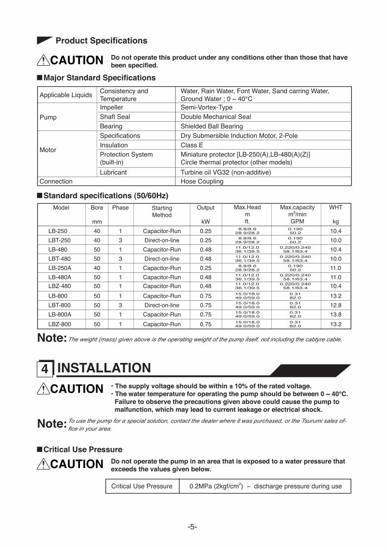
Hose Band Hose
Discharge Connection Hose Coupling
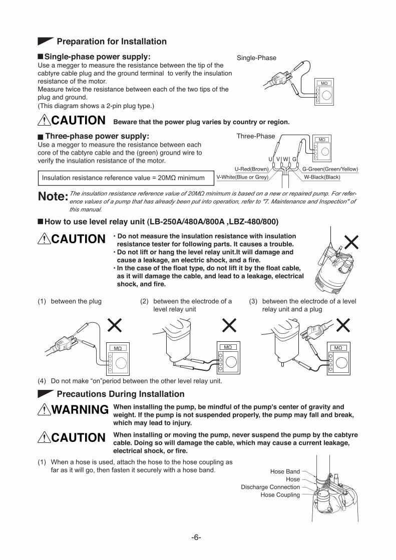
CAUTION
Note:
CAUTIONRope
Backflow Outflow
Pump stopped
(A)
(B) Cap Nut
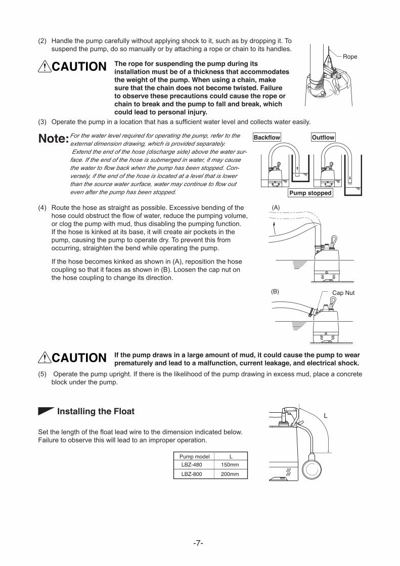
Pump model L
LBZ-800 LBZ-480 150mm
200mm

WARNING
WARNING
CAUTION
WARNING
CAUTION
CAUTION
Note:CAUTION
Single Phase
L1-Red(Brown) G-Green (Green/Yellow) L2-White(Blue)
L1 L2 G Ground
Three Phase
U-Red(Brown) G-Green (Green/Yellow) W-Black(Black)
V-White (Blue or Grey)
U V W G Ground
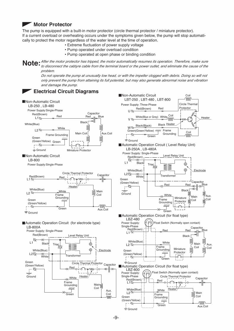
Non-Automatic Circuit LB-250 , LB-480
White(Blue)
Power Supply: Three-Phase
Non-Automatic Circuit LBT-250 , LBT-480 , LBT-800
Red(Brown) Red
Black
White(Blue or Grey)
Black(Black)
White
Green(Green/Yellow) Green
Frame Grounding
Ground
Circle Thermal Protector
Coil
Coil
Coil
Heater
Heater
U
V
W
Red Blue Black
Capacitor
Aux.Coil Main Coil
Miniature Protector
Power Supply:Single-Phase
Non-Automatic Circuit LB-800 Power Supply:Single-Phase
Red(Brown) Red
White
Green (Green/Yellow) Green
Frame Grounding
Ground
L1
L2
Automatic Operation Circuit ( Level Relay Uint) LB-250A , LB-480A
Automatic Operation Circuit (for float type)
Automatic Operation Circuit (for float type)
LBZ-480
LBZ-800
Level Relay Unit
Red Red
Ground
Red(Brown)
Black Triac
Black
White(Blue)
White
White
Green (Green/Yellow)
Green
Frame Grounding
L1
L2
Blue
Red Black
Blue
Capacitor
Aux. Coil
Main Coil Miniature
Protector
Transformer Electrode
Automatic Operation Circuit (for electrode type) LB-800A Power Supply: Single-Phase
Level Relay Unit
Red
Ground
Red(Brown)
Black Triac
White(Blue)
White
White
Green (Green/Yellow)
Green
Frame Grounding
L1
L2
Capacitor
Aux. Coil
Main Coil
Transformer Electrode
Power Supply: Single-Phase
Power Supply: Single-Phase
Power Supply: Single-Phase
Miniature Protector
Red
Ground
Red(Brown)
White(Blue) White
Green (Green/Yellow)
Green
Frame Grounding
Capacitor
Aux. Coil
Main Coil
Circle Thermal Protector
Circle Thermal Protector
Float Switch (Normally open contact)
Red
Ground
Red(Brown)
White(Blue) White Heater
Heater
Green (Green/Yellow)
Green
Frame Grounding
Capacitor
Aux.Coil
Main Coil
Circle Thermal Protector Red
Ground
Red(Brown)
White(Blue) White Heater
Green (Green/Yellow)
Green
Frame Grounding
Capacitor
Aux.Coil
Main Coil
L1
L2
L1
L2
L1
L2
Float Switch (Normally open contact)
Note:

CAUTIONNote:
Note:
Note:
WARNING
CAUTION
COUNTERMEASURE
WARNING
Note:
Example:
U V W G
Interchanging phases V and W
Ground

COUNTERMEASURE
COUNTERMEASURE
CAUTION
WARNING
Note:
CAUTION
V U V G W
Ground
C.W.L.
Pump Model C.W.L. (mm)
LB-250 50 LBT-250 50 LB-480 50 LBT-480 50
50LBT-800 50LB-800
U V W GGround
Note:
WARNING
CAUTION
Note:CAUTION
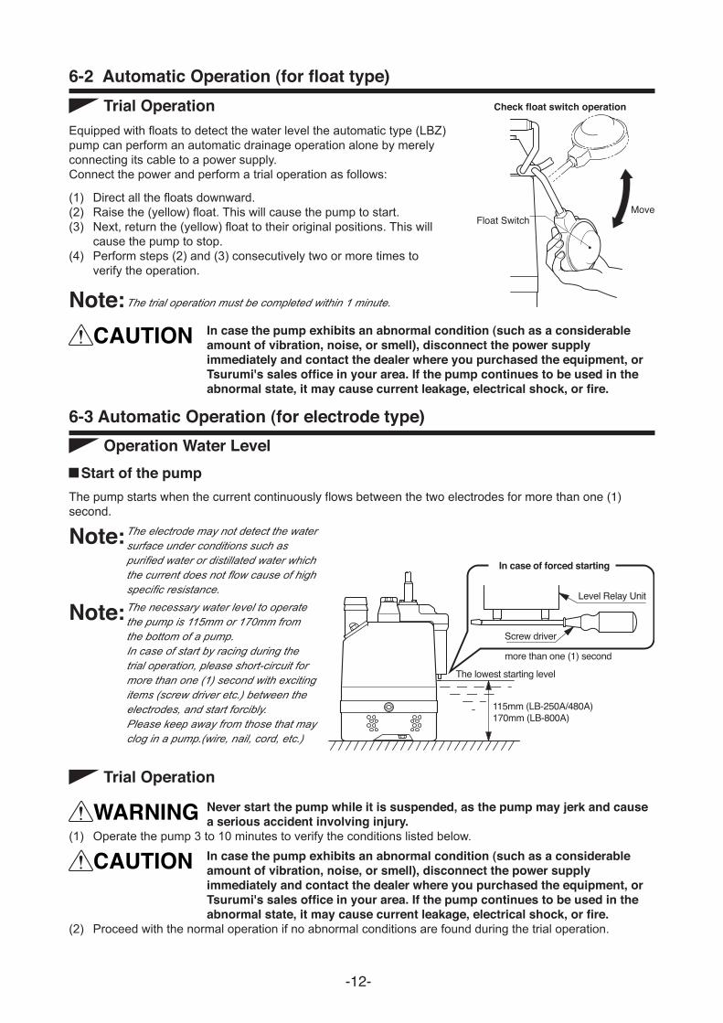
Check float switch operation
Move Float Switch
115mm (LB-250A/480A) 170mm (LB-800A)
The lowest starting level
In case of forced starting
Level Relay Unit
Screw driver more than one (1) second
Note:

Start Operation (Drainage)
Level Relay Unit Pump Water Level Condition
Drop
[Switch on]
Operation (Drainage)
Stop
Operation (Drainage)
StartOperation(Drainage)
Drop
Drop
Rise
Drop
The draining of water by the timer lasts approximately 1 minute.
(Detection Time : more than one (1) second)
(Electrodes open Trips the timer)
(Detection Time : more than one (1) second)
Level Relay Unit
Level Relay Unit Electrode
!
!
When the water level rises and the water surface comes in contact for more than one (1) second with the electrodes, the pump will restart.
The pump will stop 1 minute later.
The pump will also stop after a continuous dry run, in some cases.
If the water surface comes in contact for more than one (1) second with the electrodes within 1 minute, the pump will operate continuously even though the timer has tripped.
As the water level drops and the water surface recedes from the electrodes, the timer trips to drain water.
The electrodes of the level relay unit are submerged, causing the current to operate the pump.

WARNING
Note:
Note:
Interval
Monthly
Daily
Semi-yearly
Inspection Item
Yearly
Once every 2 to 5 years
Measuring the operating current To be within the rated current
Measuring the insulation resistance Insulation resistance reference value = 1M! minimum [NOTE] The motor must be inspected if the insulation resistance is considerably lower than the last inspection.
Inspecting oil
[NOTE] The inspection and replacement of the mechanical seal requires specialized equipment. To have this operation performed, contact the dealer where this equipment was purchased, or the Tsurumi sales office in your area.
Overhaul The pump must be overhauled even if the pump appears normal during operation. Especially, the pump may need to be overhauled earlier if it is used continuously.
[NOTE] To overhaul the pump, contact the dealer where it was purchased, or the Tsurumi sales office in your area.
1,000 hours or 6 months, whichever comes first.
Changing oilChanging the mechanical seal
2,000 hours or 12 months, whichever comes first.
Power supply voltage variation = within ±10% of the rated voltage
Measuring the power voltage
Inspection of liffting rope Replace if damage, corrosion, or wear has occurred to the rope. Remove if foreign object is attaching to it.

Note:
Note:
Hex Key Wrench Oil Plug
Packing Oil Inlet
Mechanical SealLubricant ; Turbine Oil VG 32 (non-additive)Packing, O-Ring
Part Replacement condition
V-RingShaft sleeve
When oil in oil compartment becomes milky.Every 12 mouths or after 2,000 hours of use, whichever comes first.Each time pump is disassembled or inspectedWhen ring is worn, and each time pump is disassembled or inspectedWhen it becomes worn
LB-250, LBT-250, LB-250A LB-480, LBT-480, LB-480A, LBZ-480 155
155
LB-800, LBT-800, LB-800A, LBZ-800 155
Pump Model Specified Volume
Unit : Specified Oil: Turbine Oil VG32 (non-additive)
m

WARNING
Oil Casing
Packing Oil Plug
V-Ring Shaft Sleeve
Rear Liner
Impeller
Plain Washer Spring Washer Hex. Cap Nut
Pump Casing
Suction Cover
Strainer Stand
Hex. Bolt

Note:
Do not apply oil here
V-Ring
Shaft Motor Side
Shaft Sleeve

WARNING
Contact the electric power company or an electrical repair shop. Connect the plug. Check whether there is an open circuit in the cabtyre cable or wiring. Remove obstacles and check the operation of the float. Use sandpaper to remove the debris. Repair or replace the level relay unit.
No proper power is supplied (i.e. power outage). Plug is not inserted. Open circuit in cabtyre cable or poor connection. Malfunction in float. Electrode is insulated by debris. Malfunction in level relay unit.
Inspect the pump and remove the debris. Remove obstacles and check the operation of the stop float. Provide the rated voltage or use an extension cable that meets the specifications. Check the nameplate and replace the pump or the impeller. Remove the debris from the strainer stand. Repair or replace. Place a concrete block under the pump to prevent the pump from drawing in excess mud.
Foreign matter is wedged in the impeller, causing the motor protector to trip. The movement of the stop float is obstructed, causing the start float alone to perform the start and stop operations. The voltage is too low. A 50Hz unit is used at 60Hz. The pump has been operated for a long time with its strainer stand clogged. Malfunction of motor (seizure or water leakage). The pump is drawing in too much mud.
Replace the bearings. Motor bearings are damaged. Remove the blockage. Or, replace the part. Set the water level of the (stop) float higher than the pump's minimum possible operating water level. Repair or replace the level relay unit. Use sandpaper to remove the debris. Check whether there are any wires that are tangled around the electrode. Check whether there are any electrical devices that could generate electro-magnetic interference, and relocate the unit as necessary.
The movement of the floats is obstructed. The switch in a float is faulty. The water level of the (stop) float is set lower than the pump's minimum possible operating water level. Malfunction in level relay unit Electrode is shorted by debris. Influence by electrical device in the vicinity of the pump.
Replace the impeller. Minimize the bends of the hose, and if the pump is used in a dusty area, place it inside a mesh basket during operation. Remove the debris from the strainer stand.Place a concrete block under the pump to prevent the pump from drawing in excess mud. Change the power connection. Check the nameplate and replace the pump or the impeller.
The impeller is worn. The hose is clogged or kinked at its midspan. The strainer stand is clogged or is buried. The motor rotates in reverse. A 60Hz pump is used at 50Hz.
Pump fails to start; or, starts but stops immediately.
Pump generates vibration or noise.
The pump does not stop automatically.
Problem Possible cause Countermeasure
Pump starts but stops immediately, causing the motor protector to trip.
The pumping volume is low.
RemarksPurchase date
Manufacturing numberProduct model