Системы азотных пружин
100
www.eoc.de Nitrogen Gas Springs
-
Upload
delta-snab -
Category
Documents
-
view
255 -
download
2
description
Системы азотных пружин
Transcript of Системы азотных пружин

www.eoc.de
Nitrogen Gas Springs
SHINWEON S&T CO.,LTD.
NITROGEN GAS SPRING
CT02052E
TSP SERIES!TSP SERIES!

W
W
WWW
WW
WWWWWWW
W WWW
WWWWWW
WWWWWW
WWWWWW
WWW
WWWWWWW
WW
WW
W
W
W
W
WW
W
W
W
W
IndiaBelgiumUnited StatesSingapore
DME: a blend of manufacturing,outsourcing and strategic partners

WW
WW
WW
W
WW
W
W
W
ChinaIndia
The DME offerGlobal service & distribution
DME, a global company, operating in over 100
countries worldwide. From automobiles and ap-
pliances to milk jugs and toothbrushes, DME tech-
nologies and services help the world’s leading
companies make your favorite products.
Success in today’s global market starts with the
best product, at the best price, in the required time
frame. To achieve this, DME provides customers
with the best blend of manufacturing, outsourc-
ing and strategic partners, managed to be deliv-
ered right on time anywhere in the world using
contemporary, sophisticated techniques.

DME’s commitment: to be an essential resource to customers around the globe

The DME offerAlways the right support
Customers of mold technologies face unprec-
edented demands for speed, cost reduction and
performance. Every day, they are pressed to find
new ways to do more with less. They need a pro-
vider with the resources to contribute to their suc-
cess, every step of the way.
Almost seven decades ago, DME revolutionized
the industry with its innovation in standard mold
base. Since then, we have built upon our expertise
to develop and offer the industry’s most compre-
hensive portfolio of injection molding supplies.

RunnerlessSolutions
Molds &Components
Surface Finishing

The DME offerTop quality products - at lower costs
We deliver a variety of mold components avail-
able in all regional standards. Thousands of high
performance, off-the-shelf and engineered solu-
tions let our customers spend more time on valu-
able cavity work. Along with a comprehensive line
of equipment and supplies, we provide the high
quality products you need to speed up assembly
and simplify operations.
Only DME can provide customers with the world-
wide resources required to compete in the mar-
kets of Injection Molds & Components, Hot
and Cold Runner Technologies as well as in Die
Set Molds & Components or Surface Finishing
Technologies.
Our products: designed to make molds
work more efficiently
22/0
3/20
11
22/0
3/20
11
DME NITROGEN GAS SPRINGAll DME products are accurately manufactured with equipments of high preci-sion such as CNC, M/C, etc., and have passed several trial tests of over one mil-lion strokes under SPM80 condition. DME looks forward to a big contribution to the die set industry by developing the TSP series which is compacter than existing gas springs.
Quality AssuranceDME gas springs come with a two-year warranty from date of shipping from the warehouse or one million strokes. Every troubleshooting service and (or) exchange of parts during this term is free. Also, should any critical defects arise after the two-year guarantee period, the products shall be replaced free of charge.
Maintenance DME gas springs are manufactured based on a simple structure , which re-quires no repairthroughout their lifetime. DME gas springs that are damaged during operations after use can be easily repaired by simply replacing the damaged parts . In addition, adequate load can be specified by directly adjust-ing the pressure on site.
Fast DeliveryIn order to ensure fast deliveries and support parts for A/S, DME is equipped with requirements such as procurements of load testing facilities , gas charg-ing facilities and a comprehensiveinventory for all spare parts. We also carry sufficient stock for certain models to minimize lead-timeand to reduce dead-lock in production. Models that are out of stock can be delivered within 7 days. However, this lead-time varies according to quantity and location.
Notice• Although there is a tap of M6 or M8 on top of the piston rod for assembly and a
disassembly, this should not be used to fix the gas springs or for any connect-ing devices.
• During the installation, please ensure that there is about 1mm of margin space between the contact surface and the upper part of the piston rods, Also, there is no need for pre - pressure because the initial pressure is strong enough. Any increase of pre-pressure can damage the molds.
• DME gas springs must be used as is. Do not cut or grind the upper part of the piston rods or grind the lower part of the gas springs, as it is dangerous. Any change on the gas spring can shorten its life and cause a malfunction.
• When installing the springs, please ensure that the bottom surface of the springs touch the mold to absorb the load of gas spring. However, when as-sembling with mounts, there should be space between the mount and the bottom surface of the mold. This is to prevent the mold from breaking should heavy load breaks the mount.

22/0
3/20
11
22/0
3/20
11
www.eoc.de - 1
Content
CHANGEE
GASSPRING GASSPRING
*MODEL*NAME
*PAGE
*TSP SERIES
*GAS SPRING
*P8~31
*TSM SERIES
*GAS SPRING
*P32~47
*TSS SERIES
*GAS SPRING
*P48~57
*TSL SERIES
*GAS SPRING
*P58~73
*PAN3
*CONTROL PANEL*P74
*PAN6
*CONTROL PANEL
*P75
*PSS
*MULTI PANEL
*P76
*HB10.CB4.CB12*DISTRIBUTION BLOCK
*P77
*COMPACT FITTING
*FITTING*P78
*GF FITTING
*FITTING*P79
*VF FITTING
*FITTING*P80
*CHARGING DATA
*FITTING*P81
*ACCUMULATOR
*
*P82
PRESSURE DISPERSION TANK
*HOSE MANUAL
*FITTING*P83
*FITTING EXAMPLE I,II
*FITTING*P84~85
*CHARGING
*ACCESSARIES*P86
*REPAIR TOOL
*TOOLS*P87
*PIPING CHANGE PROCEDURE
*GAS SPRING*P88
*TECHNICAL DATA
*GAS SPRING*P89~90
TECHNICAL DATA
22/0
3/20
11
22/0
3/20
11
2 - www.eoc.de
22/0
3/20
11
22/0
3/20
11
Gas Springs
Info Installation and operation
When installing the DME gas spring, the piston rods of the gas springs must be installed parallel to the operation direction and vertical to the installation ground. Failure to do so will result in the generation of odd load and abrasion of piston rods, bearings, and seals etc., which will reduce the life span of the gas spring.
To prevent damage to the gas spring and to maximize its life span, please allow 10% margin to the standard stroke to reduce shock that is caused by the compression of gas. The margin can prevent damage on the gas spring when the piston rod touches the bottom surface and shortening a lifespan due to the impact by maximum gas pressure.
WarningWith gas spring fully charged with high pressure gas, non-compliance with this warning may lead to accidents , product damages , malfunctions , etc . Before using the spring , make sure to fully understand and observe the warning below.

22/0
3/20
11
22/0
3/20
11
22/0
3/20
11
22/0
3/20
11
www.eoc.de - 3
Gas Springs
TOSS GAS SPRING
Info
System types
Model
EOC gas springs are available from 500N to 100,000N of initial force and from 10mm to 300mm of stroke.Depending on total length, EOC Normalien gas springs provide a wide range to choose from TSP , TSM , TSS and TSL series, and they are easy to use in small molds.Also, EOC Normalien gas springs are available for self contained type, individually used as an independent gas spring, and fitting system type, multiple gas springs that is connected by pipes to adjust gas pressure simultaneously for each gas spring. Conversion between those two types is possible.Recharging and discharging are simple and pressure can be adjusted easily.The maximum gas pressure for each model can be 150~180 bar.
Self-contained typeAlready charged when shipped, it can be easily used, as it does not need extra space for installation of other parts. It may be discharged and recharged with a maximum charging pressure of 150~180 bar.
Self-contained typeHoses connect with a few gas springs together and each gas spring can be simultaneously chargedand discharged. They are easily handled during operations as the control panel controls pressure for each gas spring. The maximum charging pressure is 150 bar.
22/0
3/20
11
22/0
3/20
11
4 - www.eoc.de
22/0
3/20
11
22/0
3/20
11
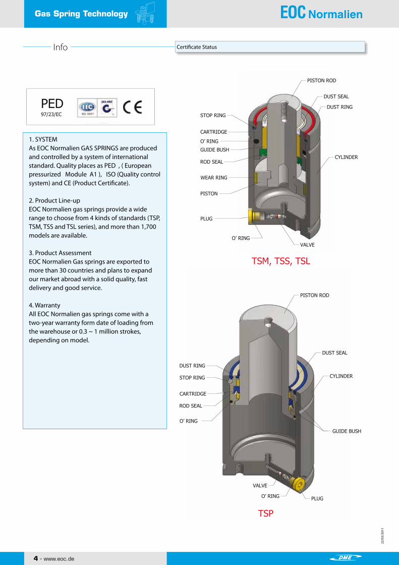
Gas Spring Technology
GUIDE BUSH
CARTRIDGE
ROD SEAL
STOP RING
DUST RING
DUST SEAL
PLUG
VALVE
CYLINDER
PISTON ROD
O’ RING
O’ RING
PISTON ROD
DUST SEAL
O’ RING
DUST RING
STOP RING
CARTRIDGE
GUIDE BUSH
ROD SEAL
WEAR RING
PISTON
PLUG
O’ RING VALVE
TSM, TSS, TSL
TSP
PED97/23/EC
CYLINDER
Info Certificate Status
1. SYSTEMAs EOC Normalien GAS SPRINGS are produced and controlled by a system of international standard. Quality places as PED , ( European pressurized Module A1 ), ISO (Quality control system) and CE (Product Certificate).
2. Product Line-upEOC Normalien gas springs provide a wide range to choose from 4 kinds of standards (TSP, TSM, TSS and TSL series), and more than 1,700 models are available.
3. Product AssessmentEOC Normalien Gas springs are exported to more than 30 countries and plans to expand our market abroad with a solid quality, fast delivery and good service.
4. WarrantyAll EOC Normalien gas springs come with a two-year warranty form date of loading from the warehouse or 0.3 ~ 1 million strokes, depending on model.

22/0
3/20
11
22/0
3/20
11
22/0
3/20
11
22/0
3/20
11
www.eoc.de - 5
Application Examples

22/0
3/20
11
22/0
3/20
11
www.eoc.de
TSP Series
SHINWEON S&T CO.,LTD.
NITROGEN GAS SPRING
CT02052E
TSP SERIES!TSP SERIES!
22/0
3/20
11
22/0
3/20
11
www.eoc.de - 7
www.eoc.de
NITROGEN GAS SPRING TOSS GAS SPRING
CONTENTS
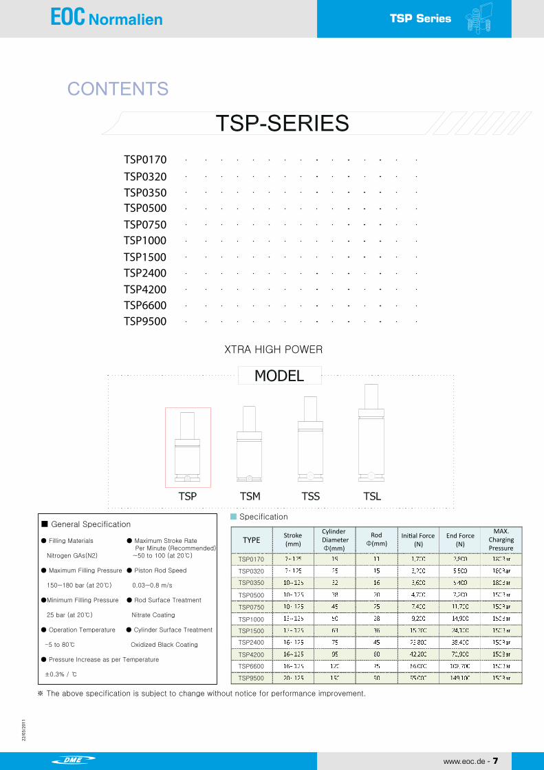
TSP0170TSP0320TSP0350TSP0500TSP0750TSP1000TSP1500TSP2400TSP4200TSP6600TSP9500
XTRA HIGH POWER
■ General Specification
● Filling Materials ● Maximum Stroke Rate Per Minute (Recommended) Nitrogen GAs(N2) ~50 to 100 (at 20℃) ● Maximum Filling Pressure ● Piston Rod Speed 150~180 bar (at 20℃) 0.03~0.8 m/s
●Minimum Filling Pressure ● Rod Surface Treatment 25 bar (at 20℃) Nitrate Coating
● Operation Temperature ● Cylinder Surface Treatment -5 to 80℃ Oxidized Black Coating
● Pressure Increase as per Temperature
±0.3% / ℃
※ The above specification is subject to change without notice for performance improvement.
■ Specification
TYPE Stroke (mm)
CylinderDiameter Φ(mm)
Rod Φ(mm)
Initial Force (N)
End Force (N)
MAX.ChargingPressure
TSP0170
TSP0320
TSP0350
TSP0500
TSP0750
TSP1000
TSP1500
TSP2400
TSP4200
TSP6600
TSP9500
TSP Series
22/0
3/20
11
22/0
3/20
11
8 - www.eoc.de
22/0
3/20
11
22/0
3/20
11
TSP0170
Copyright ⓒ2010 by SHINWEON S&T CO.,LTDAll Rights ReservedSHINWEON S&T CO.,LTD.
www.shinweon.com TSP/10
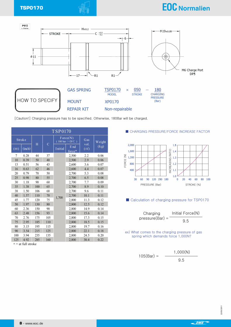
HOW TO SPECIFY
GAS SPRING
MOUNT
REPAIR KIT Non-repairable
XP0170
MODEL STROKE CHARGINGPRESSURE (Bar)
[Caution!] Charging pressure has to be specified. Otherwise, 180Bar will be charged.
Stroke
TSP0170
TSP0170
(mm)H C
Force (N)(180 bar / +20 ℃)
Initial
Gasvol.(㎤)
■ CHARGING PRESSURE/FORCE INCREASE FACTOR
■ Calculation of charging pressure for TSP0170
ex) What comes to the charging pressure of gas spring which demands force 1,000N?
FO
RC
E (
N)
INC
REASIN
G R
ATIO
PRESSURE (Bar) STROKE (%)
Chargingpressure(Bar)
Initial Force(N)
9.5
105(Bar)1,000(N)
9.5
*= at full stroke
7 0.28 44 37 2,500 2.2 0.0610 0.39 50 40 2,500 2.9 0.0613 0.51 56 43 2,600 3.6 0.0716 0.63 62 46 2,600 4.4 0.0720 0.79 70 50 2,700 5.3 0.0825 0.98 80 55 2,700 6.5 0.0830 1.18 90 60 2,700 7.7 0.0935 1.38 100 65 2,700 8.9 0.1038 1.50 106 68 2,700 9.6 0.1140 1.57 110 70 2,700 10.1 0.1145 1.77 120 75 2,800 11.3 0.1250 1.97 130 80 2,800 12.5 0.1260 2.36 150 90 2,800 14.9 0.1463 2.48 156 93 2,800 15.6 0.1470 2.76 175 105 2,800 17.3 0.1575 2.95 185 110 2,800 18.5 0.1580 3.15 195 115 2,800 19.7 0.1690 3.54 215 125 2,800 22.1 0.18
100 3.94 235 135 2,800 24.5 0.20125 4.92 285 160 2,800 30.4 0.22
H C
TSP 0170
Weight(k g)E nd
force*
Strok e Force(N) Gasvol.(㎤)
( 180 bar / +20℃ )
(㎜)
1,700
(inch) I nitial
TSP0170

22/0
3/20
11
22/0
3/20
11
22/0
3/20
11
22/0
3/20
11
www.eoc.de - 9
SHINWEON S&T CO.,LTD.
XG0170 MOUNT XC0170 MOUNT
XP0170 MOUNT
TSP0170 Mounts
25
32
45 Ø
7
20.5
2 × Ø7
25
32
Ø45
710
2 × Ø7
30
25 12
45 Ø
4 × Ø7
9
21.5
TSP0170 Mounts

22/0
3/20
11
22/0
3/20
11
10 - www.eoc.de
22/0
3/20
11
22/0
3/20
11
STROKE
M6 Charge Port DP5
Copyright ⓒ2010 by SHINWEON S&T CO.,LTDAll Rights ReservedSHINWEON S&T CO.,LTD.
www.shinweon.com TSP/12
TSP0320 NITROGEN GAS SPRING
HOW TO SPECIFY
GAS SPRING
MOUNT
REPAIR KIT Non-repairable
XP0320
MODEL STROKE CHARGINGPRESSURE (Bar)
[Caution!] Charging pressure has to be specified. Otherwise, 180Bar will be charged.
TSP0320
TSP0320Force (N)
(180 bar / +20 ℃)
■ CHARGING PRESSURE/FORCE INCREASE FACTOR
■ Calculation of charging pressure for TSP0320
ex) What comes to the charging pressure of gas spring which demands force 2,500N?
FO
RC
E (
N)
INC
REASIN
G R
ATIO
PRESSURE (Bar) STROKE (%)
Chargingpressure(Bar)
Initial Force(N)
17.7
141(Bar)2,500(N)
17.7
*= at full stroke
7 0.28 44 37 5,000 3.7 0.0910 0.39 50 40 5,000 4.9 0.1113 0.51 56 43 5,100 6.2 0.1116 0.63 62 46 5,200 7.4 0.1220 0.79 70 50 5,200 9.0 0.1425 0.98 80 55 5,300 11.1. 0.1530 1.18 90 60 5,300 13.1 0.1635 1.38 100 65 5,400 15.2 0.1838 1.50 106 68 5,400 16.4 0.1840 1.57 110 70 5,400 17.2 0.1945 1.77 120 75 5,400 19.3 0.2150 1.97 130 80 5,400 21.3 0.2260 2.36 150 90 5,500 25.4 0.2563 2.48 156 93 5,500 26.6 0.2670 2.76 175 105 5,500 29.5 0.2875 2.95 185 110 5,500 31.6 0.2880 3.15 195 115 5,500 33.6 0.3290 3.54 215 125 5,500 37.7 0.33
100 3.94 235 135 5,500 41.8 0.36125 4.92 285 160 5,500 52.0 0.43
TSP 0320
(㎜) (inch)
Gasvol.(㎤)
( 180 bar / +20℃ )Force(N)
CWeight
(k g)
3,200
I nitial E ndforce*
Strok eH
TSP0320

22/0
3/20
11
22/0
3/20
11
22/0
3/20
11
22/0
3/20
11
www.eoc.de - 11
XR0320(SR0150) MOUNT XB0320(SB0150) MOUNT
XG0320(SG0150) MOUNT
TSP0320 Mounts
50 Ø
Ø38
27
9
21.5
2840
28
40
20
9
21.5
18
30
34
50 Ø
4 × Ø7
5 × Ø7
4 × Ø7
SHINWEON S&T CO.,LTD.
Copyright ⓒ2010 by SHINWEON S&T CO.,LTDAll Rights Reserved
www.shinweon.com TSP/13
NITROGEN GAS SPRINGTSP0320 Mounts

22/0
3/20
11
22/0
3/20
11
12 - www.eoc.de
22/0
3/20
11
22/0
3/20
11
Copyright ⓒ2010 by SHINWEON S&T CO.,LTDAll Rights ReservedSHINWEON S&T CO.,LTD.
www.shinweon.com TSP/14
TSP0350 NITROGEN GAS SPRING
STROKE
HOW TO SPECIFY
GAS SPRING
MOUNT
REPAIR KIT RCX0350
XP0350
MODEL STROKE SELF CONTAINED-SFITTING-SYSTEM-F
[Caution!] Charging pressure has to be specified. Otherwise, 180Bar will be charged.
Stroke
TSP0350
TSP0350Force (N)
(180 bar / +20 ℃)
■ CHARGING PRESSURE/FORCE INCREASE FACTOR
■ Calculation of charging pressure for TSP0350
ex) What comes to the charging pressure of gas spring which demands force 3,300N?
FO
RC
E (
N)
INC
REASIN
G R
ATIO
PRESSURE (Bar) STROKE (%)
Chargingpressure(Bar)
Initial Force(N)
20.1
164(Bar)3,300(N)
20.1
*= at full stroke
Charge Port M6
2 x M6 DP6
CHARGINGPRESSURE (Bar)
M6Maintenance only
10 0.39 50 40 5,000 7.2 0.2013 0.51 56 43 5,100 9.0 0.2116 0.63 62 46 5,200 10.8 0.2120 0.79 70 50 5,200 13.3 0.2325 0.98 80 55 5,200 16.3 0.2530 1.18 90 60 5,300 19.4 0.2635 1.38 100 65 5,300 22.4 0.2838 1.50 106 68 5,300 24.2 0.2940 1.57 110 70 5,300 25.4 0.2945 1.77 120 75 5,300 28.5 0.3250 1.97 130 80 5,300 31.5 0.3360 2.36 150 90 5,300 37.6 0.3763 2.48 156 93 5,300 39.5 0.3770 2.76 170 100 5,300 43.7 0.4075 2.95 180 105 5,300 46.8 0.4180 3.15 190 110 5,300 49.8 0.4390 3.54 210 120 5,300 55.9 0.46
100 3.94 230 130 5,400 62.5 0.49125 4.92 280 155 5,400 77.2 0.58
3,600
E ndforce*
Gasvol.(㎤)
( 180 bar / +20℃ )
(㎜) (inch) I nitial
Strok e Force(N)Weight
(k g)
TSP 0350
H C
TSP0350
22/0
3/20
11
22/0
3/20
11
22/0
3/20
11
22/0
3/20
11
www.eoc.de - 13
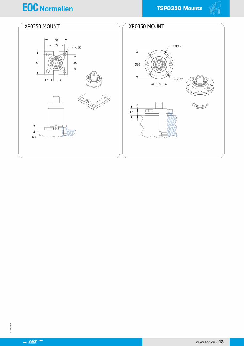
XP0350 MOUNT XR0350 MOUNT
TSP0350 Mounts
6.5
3550
12
35
50
4 × Ø7
9
17
35
Ø60
Ø49.5
4 × Ø7
SHINWEON S&T CO.,LTD.
Copyright ⓒ2010 by SHINWEON S&T CO.,LTDAll Rights Reserved
www.shinweon.com TSP/15
NITROGEN GAS SPRINGTSP0350 Mounts

22/0
3/20
11
22/0
3/20
11
14 - www.eoc.de
22/0
3/20
11
22/0
3/20
11
STROKE
Charge Port M6
2 x M6 DP6
M6Maintenance only
Copyright ⓒ2010 by SHINWEON S&T CO.,LTDAll Rights ReservedSHINWEON S&T CO.,LTD.
www.shinweon.com TSP/16
TSP0500 NITROGEN GAS SPRING
HOW TO SPECIFY
GAS SPRING
MOUNT
REPAIR KIT RCX0500
XP0500
MODEL STROKE SELF CONTAINED-SFITTING-SYSTEM-F
[Caution!] Charging pressure has to be specified. Otherwise, 150Bar will be charged.
TSP0500
TSP0500 ■ CHARGING PRESSURE/FORCE INCREASE FACTOR
■ Calculation of charging pressure for TSP0500
ex) What comes to the charging pressure of gas spring which demands force 4,000N?
FO
RC
E (
N)
INC
REASIN
G R
ATIO
PRESSURE (Bar) STROKE (%)
Chargingpressure(Bar)
Initial Force(N)
31.4
127(Bar)4,000(N)
31.4
*= at full stroke
CHARGINGPRESSURE (Bar)
10 0.39 50 40 6,700 10.4 0.2613 0.51 56 43 6,800 13.1 0.2816 0.63 62 46 6,900 15.7 0.2920 0.79 70 50 7,000 19.3 0.3125 0.98 80 55 7,000 23.7 0.3330 1.18 90 60 7,100 28.2 0.3635 1.38 100 65 7,100 32.6 0.3838 1.50 106 68 7,100 35.3 0.3940 1.57 110 70 7,100 37.0 0.4145 1.77 120 75 7,100 41.5 0.4350 1.97 130 80 7,200 45.9 0.4660 2.36 150 90 7,200 54.8 0.5163 2.48 156 93 7,200 57.4 0.5270 2.76 170 100 7,200 63.6 0.5575 2.95 180 105 7,200 68.1 0.5780 3.15 190 110 7,200 72.5 0.6090 3.54 210 120 7,200 81.4 0.65100 3.94 230 130 7,200 90.3 0.70125 4.92 280 155 7,200 112.4 0.82
4,700
( 150 bar / +20℃ )
(㎜) (inch) I nitialH C
Weight(k g)
TSP 0500
E ndforce*
Strok e Force(N) Gasvol.(㎤)
TSP0500

22/0
3/20
11
22/0
3/20
11
22/0
3/20
11
22/0
3/20
11
www.eoc.de - 15
TSP0500 Mounts
XP0500(SP0300) MOUNT XR0500(SR0300) MOUNT
XT0500(ST0300) MOUNT XC0500(SC0300) MOUNT
TSP0500 Mounts
4055
4055
124 × Ø7
6.5
Ø68
40
Ø56.5
4 × Ø7
9
17
40
52
4052
4 × Ø7
9
17
20
27.5
50.3
M6
20
7759 95
2 × Ø9
53
SHINWEON S&T CO.,LTD.
Copyright ⓒ2010 by SHINWEON S&T CO.,LTDAll Rights Reserved
www.shinweon.com TSP/17
NITROGEN GAS SPRING

22/0
3/20
11
22/0
3/20
11
16 - www.eoc.de
22/0
3/20
11
22/0
3/20
11
TSP0750
STROKE
Charge Port M6
2 x M8 DP6
M6Maintenance only
Copyright ⓒ2010 by SHINWEON S&T CO.,LTDAll Rights ReservedSHINWEON S&T CO.,LTD.
www.shinweon.com TSP/18
TSP0750 NITROGEN GAS SPRING
HOW TO SPECIFY
GAS SPRING
MOUNT
REPAIR KIT RCX0750
XP0750
MODEL STROKE SELF CONTAINED-SFITTING-SYSTEM-F
[Caution!] Charging pressure has to be specified. Otherwise, 150Bar will be charged.
Stroke
TSP0750
TSP0750 ■ CHARGING PRESSURE/FORCE INCREASE FACTOR
■ Calculation of charging pressure for TSP0750
ex) What comes to the charging pressure of gas spring which demands force 6,000N?
FO
RC
E (
N)
INC
REASIN
G R
ATIO
PRESSURE (Bar) STROKE (%)
Chargingpressure(Bar)
Initial Force(N)
49.1
122(Bar)6,000(N)
49.1
*= at full stroke
CHARGINGPRESSURE (Bar)
10 0.39 52 42 10,600 15.9 0.4013 0.51 58 45 10,900 19.8 0.4216 0.63 64 48 11,000 23.7 0.4420 0.79 72 52 11,100 28.9 0.4725 0.98 82 57 11,300 35.4 0.5030 1.18 92 62 11,300 41.9 0.5335 1.38 102 67 11,400 48.4 0.5638 1.50 108 70 11,400 52.3 0.5840 1.57 112 72 11,400 55.0 0.5945 1.77 122 77 11,500 61.5 0.6350 1.97 132 82 11,500 68.0 0.6660 2.36 152 92 11,600 81.0 0.7263 2.48 158 95 11,600 84.9 0.7470 2.76 172 102 11,600 94.0 0.7975 2.95 182 107 11,600 100.5 0.8280 3.15 192 112 11,600 107.0 0.8590 3.54 212 122 11,600 120.0 0.92100 3.94 232 132 11,700 133.0 0.98125 4.92 282 157 11,700 165.6 1.14
TSP 0750
H C
7,400
Strok e Force(N) Gasvol.(㎤)
( 150 bar / +20℃ )
(㎜) (inch) I nitial E ndforce*
Weight(k g)

22/0
3/20
11
22/0
3/20
11
22/0
3/20
11
22/0
3/20
11
www.eoc.de - 17
TSP0750 Mounts
XP0750(SP0500) MOUNT XR0750(SR0500) MOUNT
TSP0750 Mounts
XT0750(ST0500) MOUNT
XC0750(SC0500) MOUNT
XB0750(SB0500) MOUNT
6.5
5064
5064
1322
5070
5070
7050
5070
4 × Ø9
1322
86 Ø
50
Ø70.7
54
66 82 100
20
20
30
60
M8
2 × Ø9
204 × Ø9
4 × Ø9 2 × Ø9
2 × M10
2 × M8
20
20
SHINWEON S&T CO.,LTD.
Copyright ⓒ2010 by SHINWEON S&T CO.,LTDAll Rights Reserved
www.shinweon.com TSP/19
NITROGEN GAS SPRING
22/0
3/20
11
22/0
3/20
11
18 - www.eoc.de
22/0
3/20
11
22/0
3/20
11
TSP1000
Copyright ⓒ2010 by SHINWEON S&T CO.,LTDAll Rights ReservedSHINWEON S&T CO.,LTD.
www.shinweon.com TSP/20
TSP1000 NITROGEN GAS SPRING
STROKE
HOW TO SPECIFY
GAS SPRING
MOUNT
REPAIR KIT RCX1000
XP1000
MODEL STROKE SELF CONTAINED-SFITTING-SYSTEM-F
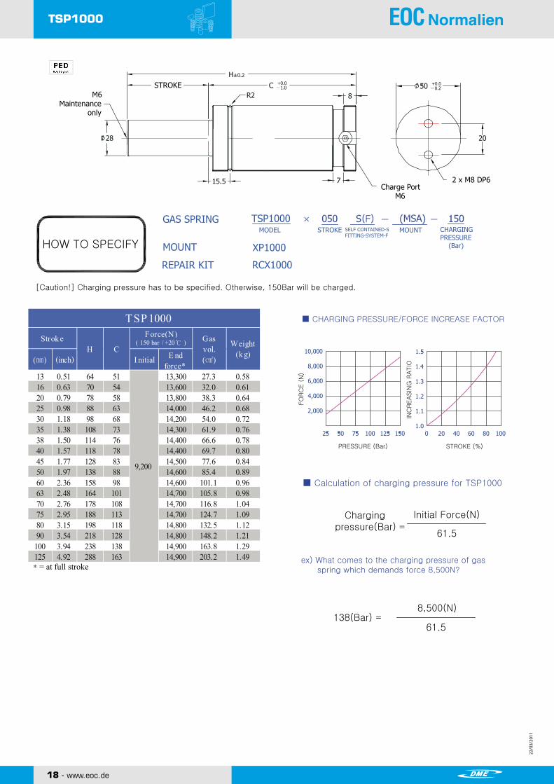
[Caution!] Charging pressure has to be specified. Otherwise, 150Bar will be charged.
TSP1000
TSP1000 ■ CHARGING PRESSURE/FORCE INCREASE FACTOR
■ Calculation of charging pressure for TSP1000
ex) What comes to the charging pressure of gas spring which demands force 8,500N?
FO
RC
E (
N)
INC
REASIN
G R
ATIO
PRESSURE (Bar) STROKE (%)
Chargingpressure(Bar)
Initial Force(N)
61.5
138(Bar)8,500(N)
61.5
*= at full stroke
Charge Port M6
2 x M8 DP6
CHARGINGPRESSURE (Bar)
M6Maintenance only
MOUNT
13 0.51 64 51 13,300 27.3 0.5816 0.63 70 54 13,600 32.0 0.6120 0.79 78 58 13,800 38.3 0.6425 0.98 88 63 14,000 46.2 0.6830 1.18 98 68 14,200 54.0 0.7235 1.38 108 73 14,300 61.9 0.7638 1.50 114 76 14,400 66.6 0.7840 1.57 118 78 14,400 69.7 0.8045 1.77 128 83 14,500 77.6 0.8450 1.97 138 88 14,600 85.4 0.8960 2.36 158 98 14,600 101.1 0.9663 2.48 164 101 14,700 105.8 0.9870 2.76 178 108 14,700 116.8 1.0475 2.95 188 113 14,700 124.7 1.0980 3.15 198 118 14,800 132.5 1.1290 3.54 218 128 14,800 148.2 1.21
100 3.94 238 138 14,900 163.8 1.29125 4.92 288 163 14,900 203.2 1.49
9,200
Weight(k g)
TSP 1000Strok e Force(N) Gas
vol.(㎤)
( 150 bar / +20℃ )
(㎜) (inch)H C
I nitial E ndforce*

22/0
3/20
11
22/0
3/20
11
22/0
3/20
11
22/0
3/20
11
www.eoc.de - 19
TSP1000 Mounts
TSP1000 Mounts
MDA
MDB
MSA
MSB
89111
30
2 × Ø11
20
5476
54764 × Ø11
25
24
56.575
56.575
12
4 × Ø9
17 17
24 24
68 89
20
12.7
56.575
2 × M8
20 70
70
4 × Ø9 1322
56.5
56.5
Ø95
Ø80
4 × Ø9
1322
11090 130
2 × Ø9
30M8
2040
80
70
56.5
4 × Ø11
2 × M1020
2 × Ø9
SHINWEON S&T CO.,LTD.
Copyright ⓒ2010 by SHINWEON S&T CO.,LTDAll Rights Reserved
www.shinweon.com TSP/21
NITROGEN GAS SPRING
MD MOUNT MS MOUNT
MK MOUNT
WELDED WELDED
WELDED XP1000(SP0750) MOUNT
XB1000(SB0750) MOUNT XT1000(ST0750) MOUNT
XR1000(SR0750) MOUNT XC1000(SC0750) MOUNT

22/0
3/20
11
22/0
3/20
11
20 - www.eoc.de
22/0
3/20
11
22/0
3/20
11
TSP1500
STROKE
Charge Port M6
2 x M8 DP6
M6Maintenance only
Copyright ⓒ2010 by SHINWEON S&T CO.,LTDAll Rights ReservedSHINWEON S&T CO.,LTD.
www.shinweon.com TSP/22
TSP1500 NITROGEN GAS SPRING
HOW TO SPECIFY
GAS SPRING
MOUNT
REPAIR KIT RCX1500
XP1500
MODEL STROKE SELF CONTAINED-SFITTING-SYSTEM-F
[Caution!] Charging pressure has to be specified. Otherwise, 150Bar will be charged.
TSP1500
■ CHARGING PRESSURE/FORCE INCREASE FACTOR
■ Calculation of charging pressure for TSP1500
ex) What comes to the charging pressure of gas spring which demands force 12,000N?
FO
RC
E (
N)
INC
REASIN
G R
ATIO
PRESSURE (Bar) STROKE (%)
Chargingpressure(Bar)
Initial Force(N)
101.7
118(Bar)12,000(N)
101.7
*= at full stroke
CHARGINGPRESSURE (Bar)
MOUNT
13 0.51 70 57 20,900 48.8 1.0416 0.63 76 60 21,400 56.8 1.0820 0.79 84 64 21,900 67.4 1.1325 0.98 94 69 22,300 80.7 1.2030 1.18 104 74 22,600 93.9 1.2735 1.38 114 79 22,900 107.2 1.3438 1.50 120 82 23,000 115.2 1.3740 1.57 124 84 23,000 120.5 1.4045 1.77 134 89 23,200 133.7 1.4750 1.97 144 94 23,300 147.0 1.5860 2.36 164 104 23,500 173.5 1.6663 2.48 170 107 23,600 181.5 1.7170 2.76 184 114 23,700 200.1 1.8075 2.95 194 119 23,800 213.3 1.8780 3.15 204 124 23,800 226.3 1.9390 3.54 224 134 23,900 252.9 2.07
100 3.94 244 144 24,000 279.5 2.19125 4.92 294 169 24,100 346.0 2.53
TSP 1500Strok e Force(N) Gas
vol.(㎤)
( 150 bar / +20℃ )
(㎜) (inch) I nitial E ndforce*
H CWeight
(k g)
15,200
22/0
3/20
11
22/0
3/20
11
22/0
3/20
11
22/0
3/20
11
www.eoc.de - 21
TSP1500 Mounts
TSP1500 Mounts
MDA
MDB
MSA
MSB
102122
30
2 × Ø11
20
6485
64854 × Ø11
25
24
6085
6085
12
4 × Ø11
21 20
26 26
83 105
30
17
73.5100
2 × M8
20 90
90
4 × Ø11 1627
73.5
60.1
Ø105
Ø85
4 × Ø11
1627
123102 146
2 × Ø11
30M8
2045
90
85
73.5
4 × Ø13
2 × M1220
2 × Ø11
SHINWEON S&T CO.,LTD.
Copyright ⓒ2010 by SHINWEON S&T CO.,LTDAll Rights Reserved
www.shinweon.com TSP/23
NITROGEN GAS SPRING
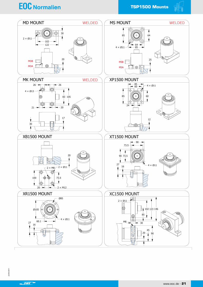
MD MOUNT MS MOUNT
MK MOUNT
WELDED WELDED
WELDED XP1500 MOUNT
XB1500 MOUNT XT1500 MOUNT
XR1500 MOUNT XC1500 MOUNT

22/0
3/20
11
22/0
3/20
11
22 - www.eoc.de
22/0
3/20
11
22/0
3/20
11
TSP2400
STROKE
Charge Port M6
M6Maintenance only
Copyright ⓒ2010 by SHINWEON S&T CO.,LTDAll Rights ReservedSHINWEON S&T CO.,LTD.
www.shinweon.com TSP/24
TSP2400 NITROGEN GAS SPRING
HOW TO SPECIFY
GAS SPRING
MOUNT
REPAIR KIT RCX2400
XP2400
MODEL STROKE SELF CONTAINED-SFITTING-SYSTEM-F
[Caution!] Charging pressure has to be specified. Otherwise, 150Bar will be charged.
TSP2400
■ CHARGING PRESSURE/FORCE INCREASE FACTOR
■ Calculation of charging pressure for TSP2400
ex) What comes to the charging pressure of gas spring which demands force 20,000N?
FO
RC
E (
N)
INC
REASIN
G R
ATIO
PRESSURE (Bar) STROKE (%)
Chargingpressure(Bar)
Initial Force(N)
159.0
126(Bar)20,000(N)
159.0
*= at full stroke
4 x M8 DP6
CHARGINGPRESSURE (Bar)
MOUNT
16 0.63 77 61 33,800 86.3 1.5820 0.79 85 65 34,600 102.4 1.6525 0.98 95 70 35,300 122.5 1.7330 1.18 105 75 35,800 142.6 1.8135 1.38 115 80 36,200 162.7 1.8938 1.50 121 83 36,400 174.8 1.9440 1.57 125 85 36,600 182.8 1.9745 1.77 135 90 36,800 203.0 2.0550 1.97 145 95 37,000 223.1 2.1360 2.36 165 105 37,400 263.3 2.3063 2.48 171 108 37,500 275.4 2.3470 2.76 185 115 37,600 303.5 2.4775 2.95 195 120 37,700 323.6 2.5580 3.15 205 125 37,800 343.8 2.6390 3.54 225 135 38,000 384.0 2.79
100 3.94 245 145 38,100 424.2 2.95125 4.92 295 170 38,400 524.8 3.37
Weight(k g)
TSP 2400
H C(inch) E nd
force*I nitial
Strok e Force(N) Gasvol.(㎤)
( 150 bar / +20℃ )
(㎜)
23,800
22/0
3/20
11
22/0
3/20
11
22/0
3/20
11
22/0
3/20
11
www.eoc.de - 23
TSP2400 Mounts
TSP2400 Mounts
MDA
MDB
MSA
MSB
120152
38
2 × Ø13
20
76102
761024 × Ø13
25
24
73.5100
73.5100
12
4 × Ø11
23 23
26 26
95 117
32
19
73.5100
4 × Ø11 4 × M8
20 90
90
4 × Ø11 1629
73.5
73.5
Ø122
Ø104
4 × Ø11
1629
137115 160
2 × Ø11
30M10
2052.5
105
85
73.5
M20 THRU
28.3
SHINWEON S&T CO.,LTD.
Copyright ⓒ2010 by SHINWEON S&T CO.,LTDAll Rights Reserved
www.shinweon.com TSP/25
NITROGEN GAS SPRING
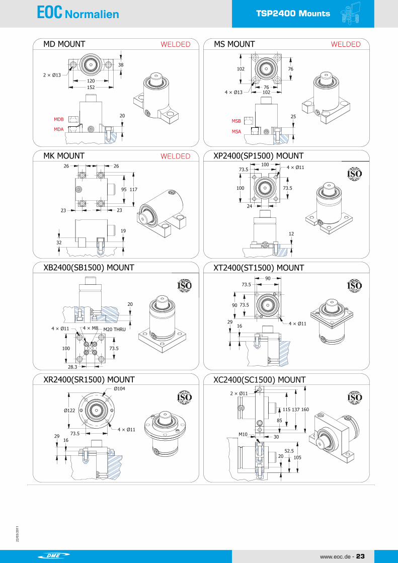
MD MOUNT MS MOUNT
MK MOUNT
WELDED WELDED
WELDED XP2400(SP1500) MOUNT
XB2400(SB1500) MOUNT XT2400(ST1500) MOUNT
XR2400(SR1500) MOUNT XC2400(SC1500) MOUNT

22/0
3/20
11
22/0
3/20
11
24 - www.eoc.de
22/0
3/20
11
22/0
3/20
11
TSP4200
4 x M8 DP12
Copyright ⓒ2010 by SHINWEON S&T CO.,LTDAll Rights ReservedSHINWEON S&T CO.,LTD.
www.shinweon.com TSP/26
TSP4200 NITROGEN GAS SPRING
STROKE
HOW TO SPECIFY
GAS SPRING
MOUNT
REPAIR KIT RCX4200
XP4200
MODEL STROKE SELF CONTAINED-SFITTING-SYSTEM-F
[Caution!] Charging pressure has to be specified. Otherwise, 150Bar will be charged.
TSP4200
■ CHARGING PRESSURE/FORCE INCREASE FACTOR
■ Calculation of charging pressure for TSP4200
ex) What comes to the charging pressure of gas spring which demands force 35,000N?
FO
RC
E (
N)
INC
REASIN
G R
ATIO
PRESSURE (Bar) STROKE (%)
Chargingpressure(Bar)
Initial Force(N)
282.6
124(Bar)35,000(N)
282.6
*= at full stroke
Charge Port G1/8
CHARGINGPRESSURE (Bar)
M8Maintenance only
MOUNT
16 0.63 90 74 60,600 150.5 3.2120 0.79 98 78 62,300 177.8 3.3225 0.98 108 83 63,800 212.0 3.4630 1.18 118 88 65,000 246.2 3.6035 1.38 128 93 65,900 280.3 3.7538 1.50 134 96 66,400 300.8 3.8240 1.57 138 98 66,600 314.5 3.8845 1.77 148 103 67,200 348.7 4.0250 1.97 158 108 67,700 382.8 4.1660 2.36 178 118 68,500 451.2 4.4463 2.48 184 121 68,700 471.7 4.5270 2.76 198 128 69,100 519.5 4.7275 2.95 208 133 69,400 553.6 4.8680 3.15 218 138 69,600 587.8 5.0090 3.54 238 148 70,000 656.1 5.27
100 3.94 258 158 70,300 724.5 5.56125 4.92 308 183 70,900 895.3 6.25
TSP 4200
H CStrok e Force(N) Gas
vol.(㎤)
( 150 bar / +20℃ )
(㎜) (inch) E ndforce*
I nitial
Weight(k g)
42,200

22/0
3/20
11
22/0
3/20
11
22/0
3/20
11
22/0
3/20
11
www.eoc.de - 25
TSP4200 Mounts
TSP4200 Mounts
MDA
MDB
MSA
MSB
98127
981274 × Ø13
25
24
92120
92120
12
4 × Ø13.5
92120
4 × Ø13.5
20 110
110
4 × Ø13.5 1833
92
92
92
Ø150
Ø130
4 × Ø13.5
1833
170145 195
2 × Ø13
30M12
2062.5
125
102.5
38
146178
2 × Ø13
20
26 26
115 137
32
23 22
19
4 × M8 M20 THRU
42.4
SHINWEON S&T CO.,LTD.
Copyright ⓒ2010 by SHINWEON S&T CO.,LTDAll Rights Reserved
www.shinweon.com TSP/27
NITROGEN GAS SPRING
MD MOUNT MS MOUNT
MK MOUNT
WELDED WELDED
WELDED XP4200(SP3000) MOUNT
XB4200(SB3000) MOUNT XT4200(ST3000) MOUNT
XR4200(SR3000) MOUNT XC4200(SC3000) MOUNT

22/0
3/20
11
22/0
3/20
11
26 - www.eoc.de
22/0
3/20
11
22/0
3/20
11
TSP6600
4 x M10 DP12
STROKE
Charge Port G1/8
M8Maintenance only
Copyright ⓒ2010 by SHINWEON S&T CO.,LTDAll Rights ReservedSHINWEON S&T CO.,LTD.
www.shinweon.com TSP/28
TSP6600 NITROGEN GAS SPRING
HOW TO SPECIFY
GAS SPRING
MOUNT
REPAIR KIT RCX6600
XP6600
MODEL STROKE SELF CONTAINED-SFITTING-SYSTEM-F
[Caution!] Charging pressure has to be specified. Otherwise, 150Bar will be charged.
TSP6600
TSP6600 ■ CHARGING PRESSURE/FORCE INCREASE FACTOR
■ Calculation of charging pressure for TSP6600
ex) What comes to the charging pressure of gas spring which demands force 60,000N?
FO
RC
E (
N)
INC
REASIN
G R
ATIO
PRESSURE (Bar) STROKE (%)
Chargingpressure(Bar)
Initial Force(N)
441.6
136(Bar)60,000(N)
441.6
*= at full stroke
CHARGINGPRESSURE (Bar)
MOUNT
16 0.63 100 84 91,900 272.3 6.0120 0.79 108 88 93,700 315.7 6.1925 0.98 118 93 96,200 370.1 6.4230 1.18 128 98 98,200 424.4 6.6535 1.38 138 103 99,700 478.7 6.8738 1.50 144 106 100,500 511.3 7.0140 1.57 148 108 101,000 533.1 7.1145 1.77 158 113 102,100 587.4 7.3350 1.97 168 118 103,000 641.8 7.5660 2.36 188 128 104,400 750.4 8.0163 2.48 194 131 104,800 783.0 8.1570 2.76 208 138 105,500 859.1 8.4775 2.95 218 143 105,900 913.4 8.7080 3.15 228 148 106,400 967.8 8.9390 3.54 248 158 107,100 1076.5 9.38
100 3.94 268 168 107,600 1185.1 9.84125 4.92 318 193 108,700 1456.8 10.98
Weight(k g)
TSP 6600
H CStrok e Force(N) Gas
vol.(㎤)
( 150 bar / +20℃ )
(㎜) (inch) I nitial E ndforce*
66,000

22/0
3/20
11
22/0
3/20
11
22/0
3/20
11
22/0
3/20
11
www.eoc.de - 27
TSP6600 Mounts
TSP6600 Mounts
MDA
MDB
MSA
MSB
114140
1141404 × Ø13
25
24
109.5140
109.5140
12
4 × Ø13.5
109.5140
4 × Ø13.5
20 130
130
4 × Ø13.5 2136
109.5
109.5
109.5
Ø175
Ø155
4 × Ø13.5
2136
195165 220
2 × Ø13
30M12
2074
148
115
38
165197
2 × Ø13
20
32 32
146 174
32
26 25
19
4 × M10M20 THRU
56.6
SHINWEON S&T CO.,LTD.
Copyright ⓒ2010 by SHINWEON S&T CO.,LTDAll Rights Reserved
www.shinweon.com TSP/29
NITROGEN GAS SPRING
MD MOUNT MS MOUNT
MK MOUNT
WELDED WELDED
WELDED XP6600(SP5000) MOUNT
XB6600(SB5000) MOUNT XT6600(ST5000) MOUNT
XR6600(SR5000) MOUNT XC6600(SC5000) MOUNT
22/0
3/20
11
22/0
3/20
11
28 - www.eoc.de
22/0
3/20
11
22/0
3/20
11
TSP9500
4 x M10 DP13
STROKE
Charge Port G1/8
M8Maintenance only
Copyright ⓒ2010 by SHINWEON S&T CO.,LTDAll Rights ReservedSHINWEON S&T CO.,LTD.
www.shinweon.com TSP/30
TSP9500 NITROGEN GAS SPRING
HOW TO SPECIFY
GAS SPRING
MOUNT
REPAIR KIT RCX9500
XP9500
MODEL STROKE SELF CONTAINED-SFITTING-SYSTEM-F
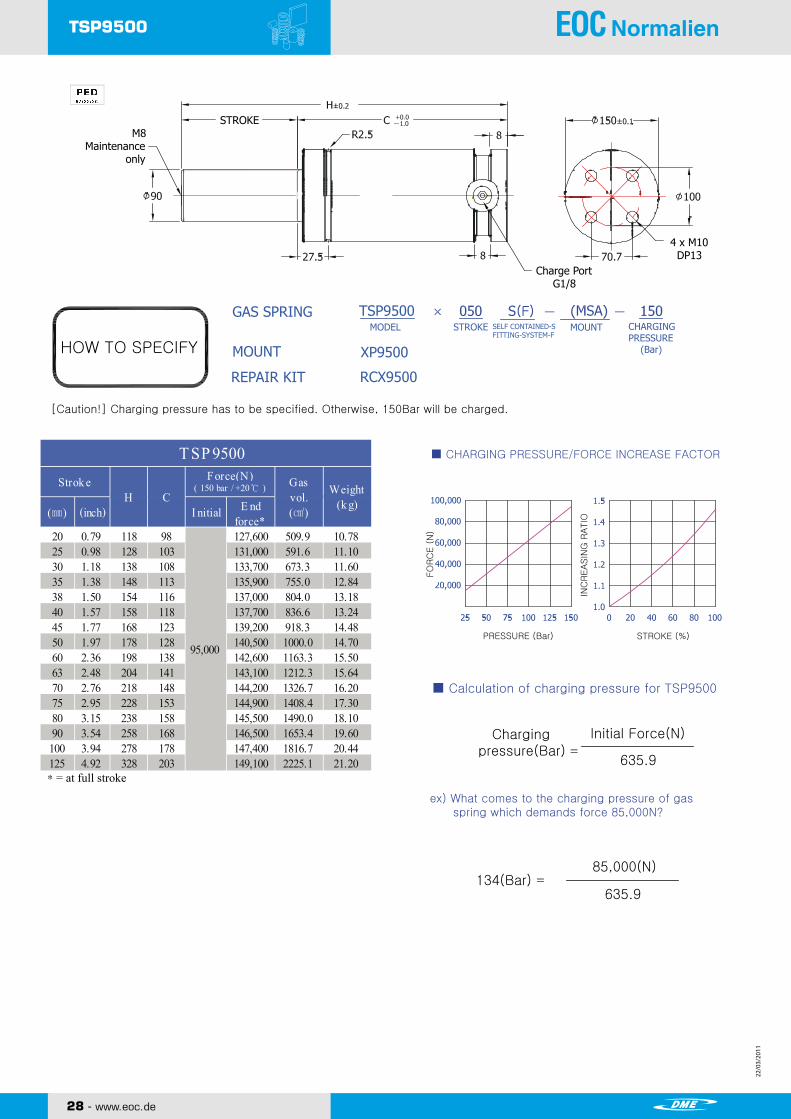
[Caution!] Charging pressure has to be specified. Otherwise, 150Bar will be charged.
TSP9500
■ CHARGING PRESSURE/FORCE INCREASE FACTOR
■ Calculation of charging pressure for TSP9500
ex) What comes to the charging pressure of gas spring which demands force 85,000N?
FO
RC
E (
N)
INC
REASIN
G R
ATIO
PRESSURE (Bar) STROKE (%)
Chargingpressure(Bar)
Initial Force(N)
635.9
134(Bar)85,000(N)
635.9
*= at full stroke
CHARGINGPRESSURE (Bar)
MOUNT
20 0.79 118 98 127,600 509.9 10.7825 0.98 128 103 131,000 591.6 11.1030 1.18 138 108 133,700 673.3 11.6035 1.38 148 113 135,900 755.0 12.8438 1.50 154 116 137,000 804.0 13.1840 1.57 158 118 137,700 836.6 13.2445 1.77 168 123 139,200 918.3 14.4850 1.97 178 128 140,500 1000.0 14.7060 2.36 198 138 142,600 1163.3 15.5063 2.48 204 141 143,100 1212.3 15.6470 2.76 218 148 144,200 1326.7 16.2075 2.95 228 153 144,900 1408.4 17.3080 3.15 238 158 145,500 1490.0 18.1090 3.54 258 168 146,500 1653.4 19.60
100 3.94 278 178 147,400 1816.7 20.44125 4.92 328 203 149,100 2225.1 21.20
Weight(k g)
TSP 9500
H CE nd
force*(㎜) (inch) I nitial
Strok e Force(N) Gasvol.(㎤)
( 150 bar / +20℃ )
95,000

22/0
3/20
11
22/0
3/20
11
22/0
3/20
11
22/0
3/20
11
www.eoc.de - 29
TSP9500 Mounts
TSP9500 Mounts
MSA
MSB
140178
140
1784 × Ø17.5
25
24
138190
138190
12
4 × Ø17.5
138190
4 × Ø17.5
25
162
162
4 × Ø17.5
2741
138
138
138
Ø220
Ø195
4 × Ø17.5
2741
230200 260
2 × Ø13
30M12
20
100
200
135
M20 THRU4 × M10
70.7
SHINWEON S&T CO.,LTD.
Copyright ⓒ2010 by SHINWEON S&T CO.,LTDAll Rights Reserved
www.shinweon.com TSP/31
NITROGEN GAS SPRING
MS MOUNT XB9500(SB7500) MOUNT
XR9500(SR7500) MOUNT
XP9500(SP7500) MOUNT
XT9500(ST7500) MOUNT
XC9500(SC7500) MOUNT
WELDED

22/0
3/20
11
22/0
3/20
11
TSM Series
SHINWEON S&T CO.,LTD.
NITROGEN GAS SPRING
CT02052E
TSP SERIES!TSP SERIES!
www.eoc.de
22/0
3/20
11
22/0
3/20
11
www.eoc.de - 31
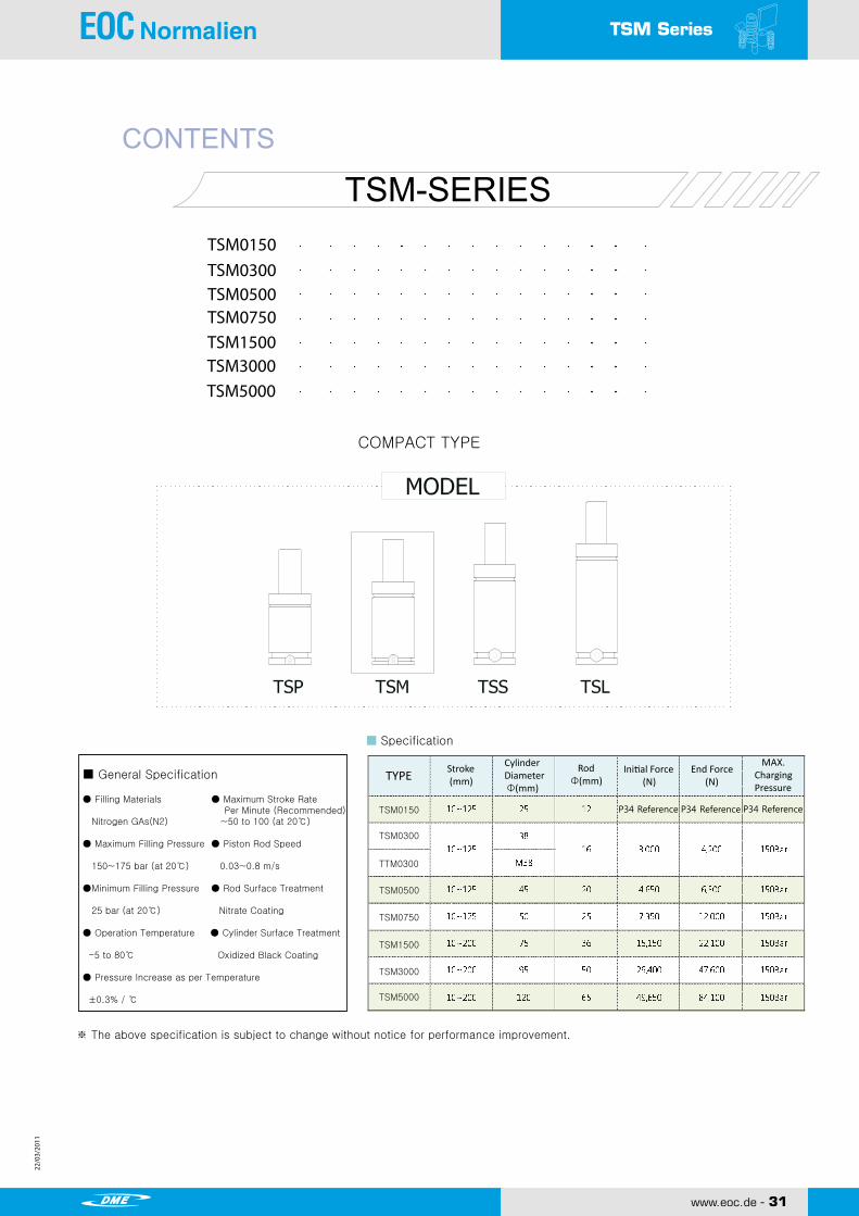
TSM SeriesNITROGEN GAS SPRING TOSS GAS SPRING
CONTENTS
TSM-SERIESTSM0150TSM0300TSM0500TSM0750TSM1500TSM3000TSM5000
COMPACT TYPE
■ General Specification
● Filling Materials ● Maximum Stroke Rate Per Minute (Recommended) Nitrogen GAs(N2) ~50 to 100 (at 20℃) ● Maximum Filling Pressure ● Piston Rod Speed 150~175 bar (at 20℃) 0.03~0.8 m/s
●Minimum Filling Pressure ● Rod Surface Treatment 25 bar (at 20℃) Nitrate Coating
● Operation Temperature ● Cylinder Surface Treatment -5 to 80℃ Oxidized Black Coating
● Pressure Increase as per Temperature
±0.3% / ℃
※ The above specification is subject to change without notice for performance improvement.
■ Specification
TYPE Stroke (mm)
CylinderDiameter Φ(mm)
Rod Φ(mm)
Initial Force (N)
End Force (N)
MAX.ChargingPressure
TSM0150
TSM0300
TTM0300
TSM0500
TSM0750
TSM1500
TSM3000
TSM5000
P34 Reference P34 Reference P34 Reference
www.eoc.de
22/0
3/20
11
22/0
3/20
11
32 - www.eoc.de
22/0
3/20
11
22/0
3/20
11
TSM0150
STROKE
STROKE (%)
FO
RC
E (
N)
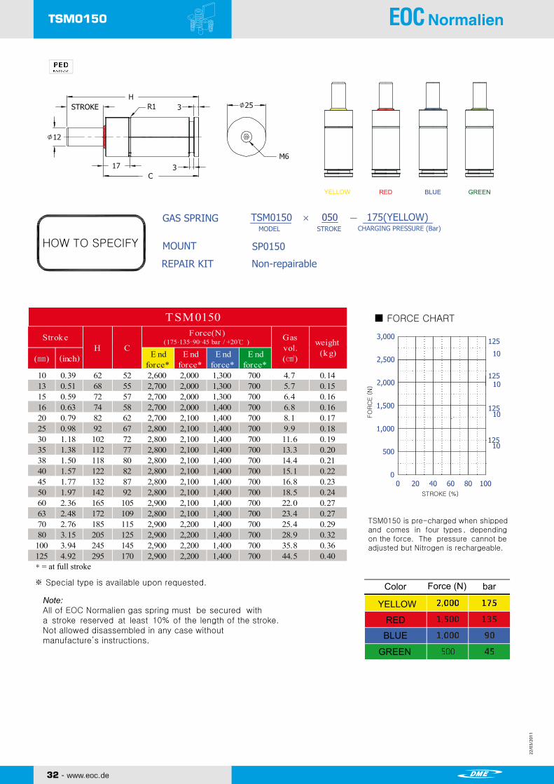
TSM0150 NITROGEN GAS SPRING
YELLOW RED BLUE GREEN
HOW TO SPECIFY
GAS SPRING
MOUNT
REPAIR KIT Non-repairable
SP0150
MODEL STROKE CHARGING PRESSURE (Bar)TSM0150 175(YELLOW)
■ FORCE CHART
TSM0150 is pre-charged when shippedand comes in four types , depending on the force. The pressure cannot beadjusted but Nitrogen is rechargeable.
Color Force (N) bar
YELLOW
RED
BLUE
GREEN
※ Special type is available upon requested.
Note:All of EOC Normalien gas spring must be secured witha stroke reserved at least 10% of the length of the stroke.Not allowed disassembled in any case withoutmanufacture’s instructions.
*= at full stroke
10 0.39 62 52 2,600 2,000 1,300 700 4.7 0.1413 0.51 68 55 2,700 2,000 1,300 700 5.7 0.1515 0.59 72 57 2,700 2,000 1,300 700 6.4 0.1616 0.63 74 58 2,700 2,000 1,400 700 6.8 0.1620 0.79 82 62 2,700 2,100 1,400 700 8.1 0.1725 0.98 92 67 2,800 2,100 1,400 700 9.9 0.1830 1.18 102 72 2,800 2,100 1,400 700 11.6 0.1935 1.38 112 77 2,800 2,100 1,400 700 13.3 0.2038 1.50 118 80 2,800 2,100 1,400 700 14.4 0.2140 1.57 122 82 2,800 2,100 1,400 700 15.1 0.2245 1.77 132 87 2,800 2,100 1,400 700 16.8 0.2350 1.97 142 92 2,800 2,100 1,400 700 18.5 0.2460 2.36 165 105 2,900 2,100 1,400 700 22.0 0.2763 2.48 172 109 2,800 2,100 1,400 700 23.4 0.2770 2.76 185 115 2,900 2,200 1,400 700 25.4 0.2980 3.15 205 125 2,900 2,200 1,400 700 28.9 0.32
100 3.94 245 145 2,900 2,200 1,400 700 35.8 0.36125 4.92 295 170 2,900 2,200 1,400 700 44.5 0.40
Strok e
(㎜) (inch) E ndforce*
H CE nd
force*
TSM0150Gasvol.(㎤)
weight(k g)E nd
force*E nd
force*
Force(N)(175·135·90·45 bar / +20℃ )

22/0
3/20
11
22/0
3/20
11
22/0
3/20
11
22/0
3/20
11
www.eoc.de - 33
TSM0150 Mounts
SP0150 MOUNT SR0150 MOUNT
SB0150 MOUNT
TSM0150 Mounts
SHINWEON S&T CO.,LTD.
Copyright ⓒ2010 by SHINWEON S&T CO.,LTDAll Rights Reserved
www.shinweon.com TSM/35
NITROGEN GAS SPRING
4 × Ø74 ×× Ø7
28
40 28
50 Ø
26.9
Ø38
4 × Ø7
34
30
50
4 × Ø7
9
21.5
28
40
40
5
28
40
5.5
9
21.5
20
18
5 × Ø7
SG0150 MOUNT

22/0
3/20
11
22/0
3/20
11
34 - www.eoc.de
22/0
3/20
11
22/0
3/20
11
TSM0300
※ Special type is available upon requested.
Copyright ⓒ2010 by SHINWEON S&T CO.,LTDAll Rights ReservedSHINWEON S&T CO.,LTD.
www.shinweon.com TSM/36
TSM0300 NITROGEN GAS SPRING
STROKE
HOW TO SPECIFY
GAS SPRING
MOUNT
REPAIR KIT RCM0300
SP0300
MODEL STROKE SELF CONTAINED-SFITTING-SYSTEM-F
[Caution!] Charging pressure has to be specified. Otherwise, 150Bar will be charged.
TSP0300
■ CHARGING PRESSURE/FORCE INCREASE FACTOR
■ Calculation of charging pressure for TSM0300
ex) What comes to the charging pressure of gas spring which demands force 2,500N?
FO
RC
E (
N)
INC
REASIN
G R
ATIO
PRESSURE (Bar) STROKE (%)
Chargingpressure(Bar)
Initial Force(N)
20.1
124(Bar)2,500(N)
20.1
Charge Port M6
2 x M6 DP6
CHARGINGPRESSURE (Bar)
M6
*= at full stroke
10 0.39 70 60 3,900 8.5 0.4415 0.59 80 65 4,000 12.0 0.4620 0.79 90 70 4,000 15.5 0.5025 0.98 100 75 4,100 19.1 0.5230 1.18 110 80 4,100 22.6 0.5635 1.38 120 85 4,100 26.1 0.5838 1.50 126 88 4,100 28.3 0.5840 1.57 130 90 4,100 29.7 0.6045 1.77 140 95 4,100 33.2 0.6250 1.97 150 100 4,100 36.7 0.6660 2.36 170 110 4,100 43.8 0.7063 2.48 176 113 4,100 45.9 0.7270 2.76 190 120 4,100 50.9 0.7680 3.15 210 130 4,100 57.9 0.8090 3.54 230 140 4,100 65.0 0.84
100 3.94 250 150 4,200 72.1 0.90110 4.33 270 160 4,200 79.1 0.96120 4.72 290 170 4,200 86.2 1.00125 4.92 300 175 4,200 89.7 1.04
weight(k g)
TSM0300
3,000
(inch)
Gasvol.(㎤)
( 150 bar / +20℃ )Force(N)
H CI nitial E nd
force*
Strok e
(㎜)

22/0
3/20
11
22/0
3/20
11
22/0
3/20
11
22/0
3/20
11
www.eoc.de - 35
TSM0300 Mounts
SN0300 MOUNT For TTM0300 SG0300 MOUNT For TTM0300
SP0300 MOUNT SR0300 MOUNT
ST0300 MOUNT SC0300 MOUNT
SHINWEON S&T CO.,LTD.
Copyright ⓒ2010 by SHINWEON S&T CO.,LTDAll Rights Reserved
www.shinweon.com TSM/37
TTM0300 (Threaded Option)
TSM0300 Mounts
68 Ø
Ø56.5
4 × Ø7 40
59 77 95
20
2 × Ø9
47
M38×1.5 29
50
4 × Ø9
M38×1.5
20
27.5
50.3
M6
25
M38×1.5 2 × M6 DP6
12
4055
4055
6.5
4 × Ø7
917
917 4 × Ø7
4052
4052
53
16
812
50
Ø75
M6
16 Ø
CST
H±0.2
+ 0.0-0.2
NITROGEN GAS SPRING

22/0
3/20
11
22/0
3/20
11
36 - www.eoc.de
22/0
3/20
11
22/0
3/20
11
TSM0500
STROKE
Charge Port M6
2 x M8 DP6
M8
※ Special type is available upon requested.
Copyright ⓒ2010 by SHINWEON S&T CO.,LTDAll Rights ReservedSHINWEON S&T CO.,LTD.
www.shinweon.com TSM/38
TSM0500 NITROGEN GAS SPRING
HOW TO SPECIFY
GAS SPRING
MOUNT
REPAIR KIT RCM0500
SP0500
MODEL STROKE SELF CONTAINED-SFITTING-SYSTEM-F
[Caution!] Charging pressure has to be specified. Otherwise, 150Bar will be charged.
TSM0500
■ CHARGING PRESSURE/FORCE INCREASE FACTOR
■ Calculation of charging pressure for TSM0500
ex) What comes to the charging pressure of gas spring which demands force 4,000N?
FO
RC
E (
N)
INC
REASIN
G R
ATIO
PRESSURE (Bar) STROKE (%)
Chargingpressure(Bar)
Initial Force(N)
31.4
127(Bar)4,000(N)
31.4
CHARGINGPRESSURE (Bar)
*= at full stroke
10 0.39 70 60 6,100 12.9 0.6015 0.59 80 65 6,200 18.3 0.6420 0.79 90 70 6,300 23.6 0.6825 0.98 100 75 6,300 29.0 0.7230 1.18 110 80 6,400 34.4 0.7635 1.38 120 85 6,400 39.8 0.8038 1.50 126 88 6,400 43.0 0.8140 1.57 130 90 6,400 45.1 0.8245 1.77 140 95 6,400 50.5 0.8650 1.97 150 100 6,400 55.9 0.8960 2.36 170 110 6,500 66.6 0.9663 2.48 176 113 6,500 69.9 0.9870 2.76 190 120 6,500 77.4 1.0180 3.15 210 130 6,500 88.1 1.0990 3.54 230 140 6,500 98.9 1.16
100 3.94 250 150 6,500 109.6 1.23110 4.33 270 160 6,500 120.4 1.30120 4.72 290 170 6,500 131.1 1.35125 4.92 300 175 6,500 136.5 1.39
weight(k g)
TSM0500
4,650
Strok e Force(N) Gasvol.(㎤)
( 150 bar / +20℃ )
(㎜) (inch) I nitial E ndforce*
CH

22/0
3/20
11
22/0
3/20
11
22/0
3/20
11
22/0
3/20
11
www.eoc.de - 37
TSM0500 Mounts
2 × Ø9 2 × Ø999
TSM0500 Mounts
6.5
86 Ø
50
Ø70.7
4 × Ø9
1323
5064
5064
1323
4 × Ø9
5070
2 × M8
2 × M10
7050
5070
4 × Ø9
20
60
54
66 82 100
20M8
20
2 × Ø9
30
705020
20
SHINWEON S&T CO.,LTD.
Copyright ⓒ2010 by SHINWEON S&T CO.,LTDAll Rights Reserved
www.shinweon.com TSM/39
NITROGEN GAS SPRING
SP0500 MOUNT SR0500 MOUNT
ST0500 MOUNT
SC0500 MOUNT
SB0500 MOUNT

22/0
3/20
11
22/0
3/20
11
38 - www.eoc.de
22/0
3/20
11
22/0
3/20
11
TSM0750
STROKE
Charge Port M6
2 x M8 DP6
M8
※ Special type is available upon requested.
Copyright ⓒ2010 by SHINWEON S&T CO.,LTDAll Rights ReservedSHINWEON S&T CO.,LTD.
www.shinweon.com TSM/40
TSM0750 NITROGEN GAS SPRING
HOW TO SPECIFY
GAS SPRING
MOUNT
REPAIR KIT RCM0750
SP0750
MODEL STROKE SELF CONTAINED-SFITTING-SYSTEM-F
[Caution!] Charging pressure has to be specified. Otherwise, 150Bar will be charged.
TSM0750
TSM0750 ■ CHARGING PRESSURE/FORCE INCREASE FACTOR
■ Calculation of charging pressure for TSM0750
ex) What comes to the charging pressure of gas spring which demands force 6,000N?
FO
RC
E (
N)
INC
REASIN
G R
ATIO
PRESSURE (Bar) STROKE (%)
Chargingpressure(Bar)
Initial Force(N)
49.1
122(Bar)6,000(N)
49.1
*= at full stroke
CHARGINGPRESSURE (Bar)
MOUNT
10 0.39 70 60 11,700 13.2 0.7512.7 0.50 75.4 62.7 11,800 16.6 0.7815 0.59 80 65 11,800 19.5 0.8020 0.79 90 70 11,900 25.7 0.8625 0.98 100 75 11,900 32.0 0.9230 1.18 110 80 11,900 38.3 0.9435 1.38 120 85 11,900 44.6 1.0238 1.50 126 88 12,000 48.4 1.0440 1.57 130 90 12,000 50.9 1.0645 1.77 140 95 12,000 57.1 1.1050 1.97 150 100 12,000 63.4 1.1460 2.36 170 110 12,000 76.0 1.2463 2.48 176 113 12,000 79.8 1.2670 2.76 190 120 12,000 88.5 1.3475 2.95 200 125 12,000 94.8 1.3880 3.15 210 130 12,000 101.1 1.4390 3.54 230 140 12,000 113.7 1.53
100 3.94 250 150 12,000 126.2 1.62125 4.92 300 175 12,000 157.6 1.84
weight(k g)
TSM0750
7,350
Strok e Force(N) Gasvol.(㎤)
( 150 bar / +20℃ )
(㎜) (inch) I nitial E ndforce*
H C

22/0
3/20
11
22/0
3/20
11
22/0
3/20
11
22/0
3/20
11
www.eoc.de - 39
TSM0750 Mounts
MK MOUNT
TSM0750 Mounts
MDA
MDB
MTB
MTA
MSA
MSB
MRA
MRB
111
19
19
C7
C7
Ø90
4 × Ø11
110 Ø
12.7
20
24 24
17
68 89
11189
30
2 × Ø11
76 54
4 × Ø11
7654
30
89
2 × Ø11
174 × Ø11
7556.5
75 56.5
24
4 × Ø9
6.5 7556.5
2 × Ø9
2 × M10
2 × M8
7056.5
24
13
70 56.5
4 × Ø9
Ø95
56.54 × Ø9
Ø80
24
13
13011090
70
2 × Ø9
30M8
8040
20
20 25
20
20
SHINWEON S&T CO.,LTD.
Copyright ⓒ2010 by SHINWEON S&T CO.,LTDAll Rights Reserved
www.shinweon.com TSM/41
NITROGEN GAS SPRING
MD MOUNT MS MOUNT MT MOUNTWELDED
WELDED
WELDED WELDED
MR MOUNT WELDED
SP0750M MOUNT SB0750 MOUNT ST0750 MOUNT
SR0750 MOUNT SC0750 MOUNT

22/0
3/20
11
22/0
3/20
11
40 - www.eoc.de
22/0
3/20
11
22/0
3/20
11
TSM1500
Copyright ⓒ2010 by SHINWEON S&T CO.,LTDAll Rights ReservedSHINWEON S&T CO.,LTD.
www.shinweon.com TSM/42
FO
RC
E (
N)
INC
REASIN
G R
ATIO
PRESSURE (Bar) STROKE (%)
Chargingpressure(Bar)
Initial Force(N)
101.7
118(Bar)12,000(N)
101.7
STROKE
TSM1500 NITROGEN GAS SPRING
HOW TO SPECIFY
GAS SPRING
MOUNT
REPAIR KIT RCM1500
SP1500
MODEL STROKE SELF CONTAINED-SFITTING-SYSTEM-F
[Caution!] Charging pressure has to be specified. Otherwise, 150Bar will be charged.
TSM1500
■ CHARGING PRESSURE/FORCE INCREASE FACTOR
■ Calculation of charging pressure for TSM1500
ex) What comes to the charging pressure of gas spring which demands force 12,000N?
Charge Port G1/8
4 x M8 DP12
M8
CHARGINGPRESSURE (Bar)
MOUNT
*= at full stroke
※ Special type is available upon requested.
10 0.39 114 104 19,000 49.9 2.0013 0.51 120 107 19,500 59.2 2.9515 0.59 124 109 19,700 65.4 3.0220 0.79 134 114 20,200 81.0 3.1325 0.98 144 119 20,500 96.6 3.2030 1.18 154 124 20,800 112.2 3.3235 1.38 164 129 20,900 127.7 3.3838 1.50 170 132 21,000 137.1 3.4740 1.57 174 134 21,100 143.3 3.4945 1.77 184 139 21,200 158.9 3.5850 1.97 194 144 21,300 174.5 3.6560 2.36 214 154 21,500 205.6 3.8363 2.48 220 157 21,500 215.0 3.8870 2.76 234 164 21,600 236.8 4.0575 2.95 244 169 21,600 252.4 4.1780 3.15 254 174 21,700 267.9 4.2490 3.54 274 184 21,800 299.1 4.34
100 3.94 294 194 21,800 330.3 4.60125 4.92 344 219 21,900 408.2 5.06150 5.91 394 244 22,000 486.0 5.54160 6.30 414 254 22,000 517.2 5.83175 6.89 444 269 22,100 563.9 6.11200 7.87 494 294 22,100 641.8 6.46
weight(k g)
TSM1500
15,150
Strok e Force(N) Gasvol.(㎤)
( 150 bar / +20℃ )
(㎜) (inch) I nitial E ndforce*
H C

22/0
3/20
11
22/0
3/20
11
22/0
3/20
11
22/0
3/20
11
www.eoc.de - 41
TSM1500 Mounts
SHINWEON S&T CO.,LTD.
Copyright ⓒ2010 by SHINWEON S&T CO.,LTDAll Rights Reserved
www.shinweon.com TSM/43
TSM1500 Mounts
MDA
MDBMTA
MSA
MSB
MRA
MRB
4 × Ø11
16
4 × Ø11
115 137 160122 Ø
19
M1073.5
Ø104
32
52.5
105
2 × Ø11
30
26 26
3232
95 118
73.5 100
4 × Ø11
20
4 × M8
4 × Ø11
120152
20
2 × Ø13
3876102
76102
25
4 × Ø13
120152
38
2 × Ø13
19
C9
MTB
Ø120
19
C9
152 Ø
4 × Ø13
73.5100
73.5
24
100
73.590
73.590
12
29
1629
85
20
4 × Ø13
11
28.3
M20 THRU
NITROGEN GAS SPRING
MK MOUNT
MD MOUNT MS MOUNT MT MOUNTWELDED
WELDED
WELDED WELDED
MR MOUNT WELDED
SP1500 MOUNT SB1500 MOUNT ST1500 MOUNT
SR1500 MOUNT SC1500 MOUNT
22/0
3/20
11
22/0
3/20
11
42 - www.eoc.de
22/0
3/20
11
22/0
3/20
11
TSM3000
STROKE
Charge Port G1/8
4 x M8 DP12
M8
Copyright ⓒ2010 by SHINWEON S&T CO.,LTDAll Rights ReservedSHINWEON S&T CO.,LTD.
www.shinweon.com TSM/44
FO
RC
E (
N)
INC
REASIN
G R
ATIO
PRESSURE (Bar) STROKE (%)
Chargingpressure(Bar)
Initial Force(N)
196.2
127(Bar)25,000(N)
196.2
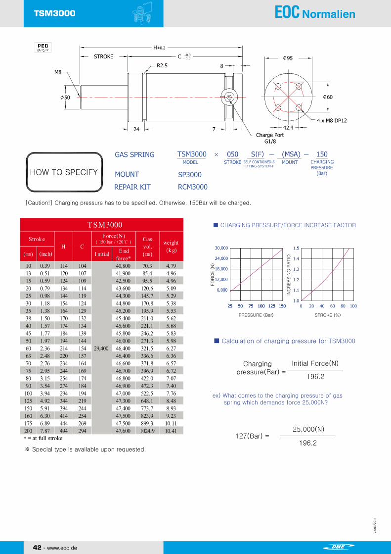
TSM3000 NITROGEN GAS SPRING
HOW TO SPECIFY
GAS SPRING
MOUNT
REPAIR KIT RCM3000
SP3000
MODEL STROKE SELF CONTAINED-SFITTING-SYSTEM-F
[Caution!] Charging pressure has to be specified. Otherwise, 150Bar will be charged.
TSM3000
■ CHARGING PRESSURE/FORCE INCREASE FACTOR
■ Calculation of charging pressure for TSM3000
ex) What comes to the charging pressure of gas spring which demands force 25,000N?
CHARGINGPRESSURE (Bar)
MOUNT
*= at full stroke
※ Special type is available upon requested.
10 0.39 114 104 40,800 70.3 4.7913 0.51 120 107 41,900 85.4 4.9615 0.59 124 109 42,500 95.5 4.9620 0.79 134 114 43,600 120.6 5.0925 0.98 144 119 44,300 145.7 5.2930 1.18 154 124 44,800 170.8 5.3835 1.38 164 129 45,200 195.9 5.5338 1.50 170 132 45,400 211.0 5.6240 1.57 174 134 45,600 221.1 5.6845 1.77 184 139 45,800 246.2 5.8350 1.97 194 144 46,000 271.3 5.9860 2.36 214 154 46,400 321.5 6.2763 2.48 220 157 46,400 336.6 6.3670 2.76 234 164 46,600 371.8 6.5775 2.95 244 169 46,700 396.9 6.7280 3.15 254 174 46,800 422.0 7.0790 3.54 274 184 46,900 472.3 7.40
100 3.94 294 194 47,000 522.5 7.76125 4.92 344 219 47,300 648.1 8.48150 5.91 394 244 47,400 773.7 8.93160 6.30 414 254 47,500 823.9 9.23175 6.89 444 269 47,500 899.3 10.11200 7.87 494 294 47,600 1024.9 10.41
weight(k g)
TSM3000
29,400
Strok e Force(N) Gasvol.(㎤)
( 150 bar / +20℃ )
(㎜) (inch) I nitial E ndforce*
CH

22/0
3/20
11
22/0
3/20
11
22/0
3/20
11
22/0
3/20
11
www.eoc.de - 43
TSM3000 Mounts
TSM3000 Mounts
MDA
MDBMTA
MSA
MSB
MRA
MRB
4 × Ø13.5
18
4 × Ø13.5
145 170 195150 Ø
19
M1292
Ø130
32
62.5
125
2 × Ø13
30
26 26
3232
115 137
92 120
4 × Ø13.5
20
4 × M8
4 × Ø13.5
146178
20
2 × Ø13
3898127
98127
25
4 × Ø13
146178
38
2 × Ø13
19
C10
MTB
Ø140
25
C10
171 Ø
4 × Ø13
92120
92
24
120
92110
92110
12
33
1833
102.5
20
4 × Ø13
.5.5
42.4 M20 THRU
SHINWEON S&T CO.,LTD.
Copyright ⓒ2010 by SHINWEON S&T CO.,LTDAll Rights Reserved
www.shinweon.com TSM/45
NITROGEN GAS SPRING
MK MOUNT
MD MOUNT MS MOUNT MT MOUNTWELDED
WELDED
WELDED WELDED
MR MOUNT WELDED
SP3000 MOUNT SB3000 MOUNT ST3000 MOUNT
SR3000 MOUNT SC3000 MOUNT

22/0
3/20
11
22/0
3/20
11
44 - www.eoc.de
22/0
3/20
11
22/0
3/20
11
TSM5000
STROKE
Charge Port G1/8
4 x M10 DP12
M8
Copyright ⓒ2010 by SHINWEON S&T CO.,LTDAll Rights ReservedSHINWEON S&T CO.,LTD.
www.shinweon.com TSM/46
FO
RC
E (
N)
INC
REASIN
G R
ATIO
PRESSURE (Bar) STROKE (%)
Chargingpressure(Bar)
Initial Force(N)
331.7
115(Bar)38,000(N)
331.7
TSM5000 NITROGEN GAS SPRING
HOW TO SPECIFY
GAS SPRING
MOUNT
REPAIR KIT RCM5000
SP5000
MODEL STROKE SELF CONTAINED-SFITTING-SYSTEM-F
[Caution!] Charging pressure has to be specified. Otherwise, 150Bar will be charged.
TSM5000
■ CHARGING PRESSURE/FORCE INCREASE FACTOR
■ Calculation of charging pressure for TSM5000
ex) What comes to the charging pressure of gas spring which demands force 38,000N?
CHARGINGPRESSURE (Bar)
MOUNT
*= at full stroke
※ Special type is available upon requested.
10 0.39 117 107 67,400 125.6 7.7813 0.51 123 110 69,800 149.2 7.9215 0.59 127 112 71,000 164.9 8.0120 0.79 137 117 73,500 204.1 8.2425 0.98 147 122 75,200 243.4 8.4830 1.18 157 127 76,500 282.6 8.7135 1.38 167 132 77,600 321.9 8.9538 1.50 173 135 78,100 345.4 9.0940 1.57 177 137 78,400 361.1 9.1845 1.77 187 142 79,100 400.4 9.4150 1.97 197 147 79,600 439.6 9.6560 2.36 217 157 80,500 518.1 10.1163 2.48 223 160 80,700 541.7 10.2570 2.76 237 167 81,200 596.6 10.5875 2.95 247 172 81,400 635.9 10.8180 3.15 257 177 81,700 675.1 11.0590 3.54 277 187 82,100 753.6 11.51
100 3.94 297 197 82,400 832.1 11.98125 4.92 347 222 83,100 1028.4 13.15150 5.91 397 247 83,500 1224.6 14.32160 6.30 417 257 83,600 1303.1 14.79175 6.89 447 272 83,800 1420.9 15.49200 7.87 497 297 84,100 1617.1 16.65
weight(k g)
TSM5000
49,650
Strok e Force(N) Gasvol.(㎤)
( 150 bar / +20℃ )
(㎜) (inch) I nitial E ndforce*
CH

22/0
3/20
11
22/0
3/20
11
22/0
3/20
11
22/0
3/20
11
www.eoc.de - 45
TSM5000 Mounts
TSM5000 Mounts
MDA
MDBMTA
MSA
MSB
MRA
MRB
4 × Ø13.5
21
4 × Ø13.5
165 195 220175 Ø
19
M12109.5
Ø155
32
74
148
2 × Ø13
30
32 32
6262
146 174
109.5 140
4 × Ø13.5
20
4 × M10
4 × Ø13.5
165197
20
2 × Ø13
38114140
114140
25
4 × Ø13
165197
38
2 × Ø13
19
C10
MTB
Ø165
25
C10
197 Ø
4 × Ø17
109.5140
109.5
24
140
109.5130
109.5130
12
36
2136
115
20
4 × Ø17
.5.5
56.6 M20 THRU
SHINWEON S&T CO.,LTD.
Copyright ⓒ2010 by SHINWEON S&T CO.,LTDAll Rights Reserved
www.shinweon.com TSM/47
NITROGEN GAS SPRING
MK MOUNT
MD MOUNT MS MOUNT MT MOUNTWELDED
WELDED
WELDED WELDED
MR MOUNT WELDED
SP5000 MOUNT SB5000 MOUNT ST5000 MOUNT
SR5000 MOUNT SC5000 MOUNT

22/0
3/20
11
22/0
3/20
11
TSS Series
SHINWEON S&T CO.,LTD.
NITROGEN GAS SPRING
CT02052E
TSP SERIES!TSP SERIES!
www.eoc.de

22/0
3/20
11
22/0
3/20
11
www.eoc.de - 47
TSS SeriesNITROGEN GAS SPRING TOSS GAS SPRING
TSS-SERIESTSS0750TSS1500TSS3000TSS5000
TSS STANDARD
■ General Specification
● Filling Materials ● Maximum Stroke Rate Per Minute (Recommended) Nitrogen GAs(N2) ~50 to 100 (at 20℃) ● Maximum Filling Pressure ● Piston Rod Speed 150~180 bar (at 20℃) 0.03~0.8 m/s
●Minimum Filling Pressure ● Rod Surface Treatment 25 bar (at 20℃) Nitrate Coating
● Operation Temperature ● Cylinder Surface Treatment -5 to 80℃ Oxidized Black Coating
● Pressure Increase as per Temperature
±0.3% / ℃
※ The above specification is subject to change without notice for performance improvement.
■ Specification
TYPE Stroke (mm)
CylinderDiameter Φ(mm)
Rod Φ(mm)
Initial Force (N)
End Force (N)
MAX.ChargingPressure
TSS0750
TSS1500
TSS3000
TSS5000
CONTENTS
www.eoc.de

22/0
3/20
11
22/0
3/20
11
48 - www.eoc.de
22/0
3/20
11
22/0
3/20
11
TSS0750
Charge Port G1/8
2 x M8 DP12
STROKE
M8
Copyright ⓒ2010 by SHINWEON S&T CO.,LTDAll Rights ReservedSHINWEON S&T CO.,LTD.
www.shinweon.com TSM/50
FO
RC
E (
N)
INC
REASIN
G R
ATIO
PRESSURE (Bar) STROKE (%)
Chargingpressure(Bar)
Initial Force(N)
49.1
122(Bar)6,000(N)
49.1
TSS0750 NITROGEN GAS SPRING
HOW TO SPECIFY
GAS SPRING
MOUNT
REPAIR KIT RCS0750
SP0750
MODEL STROKE SELF CONTAINED-SFITTING-SYSTEM-F
[Caution!] Charging pressure has to be specified. Otherwise, 150Bar will be charged.
TSM1500
■ CHARGING PRESSURE/FORCE INCREASE FACTOR
■ Calculation of charging pressure for TSS0750
ex) What comes to the charging pressure of gas spring which demands force 6,000N?
CHARGINGPRESSURE (Bar)
MOUNT
*= at full stroke
※ Special type is available upon requested.
10 0.39 90 80 9,500 21.4 1.0012.7 0.50 95.4 82.7 9,800 24.7 1.0015 0.59 100 85 10,000 27.6 1.0220 0.79 110 90 10,300 33.9 1.0625 0.98 120 95 10,600 40.2 1.1230 1.18 130 100 10,800 46.5 1.1635 1.38 140 105 10,900 52.8 1.2038 1.50 146 108 11,000 56.5 1.2440 1.57 150 110 11,000 59.0 1.2645 1.77 160 115 11,100 65.3 1.3050 1.97 170 120 11,200 71.6 1.3660 2.36 190 130 11,300 84.2 1.4563 2.48 196 133 11,300 87.9 1.4870 2.76 210 140 11,400 96.7 1.5275 2.95 220 145 11,400 103.0 1.6080 3.15 230 150 11,500 109.3 1.6490 3.54 250 160 11,500 121.8 1.74
100 3.94 270 170 11,600 134.4 1.82125 4.92 320 195 11,700 165.8 2.04150 5.91 370 220 11,700 197.2 2.30160 6.30 390 230 11,700 209.8 2.37175 6.89 420 245 11,800 228.6 2.52200 7.87 470 270 11,800 260.0 2.76
weight(k g)
TSS0750
7,350
Strok e Force(N) Gasvol.(㎤)
( 150 bar / +20℃ )
(㎜) (inch) I nitial E ndforce*
H C

22/0
3/20
11
22/0
3/20
11
22/0
3/20
11
22/0
3/20
11
www.eoc.de - 49
TSS0750 Mounts
TSS0750 Mounts
MDA
MDBMTA
MSA
MSB
MRA
MRB
4 × Ø9
13
4 × Ø9
90 110 13095 Ø
12.7
M856.5
Ø80
20
40
80
2 × Ø9
30
24 24
7171
68 89
20
4 × Ø9
89111
20
2 × Ø11
305476
5476
25
4 × Ø11
89111
30
2 × Ø11
19
C7
MTB
Ø90
19
C7
110 Ø
4 × Ø11
56.575
56.5
24
75
56.570
56.570
12
24
1324
70
20
4 × Ø11
2 × M87556.5
20
2 × Ø9
2 × M10
SHINWEON S&T CO.,LTD.
Copyright ⓒ2010 by SHINWEON S&T CO.,LTDAll Rights Reserved
www.shinweon.com TSS/51
NITROGEN GAS SPRING
MK MOUNT
MD MOUNT MS MOUNT MT MOUNTWELDED
WELDED
WELDED WELDED
MR MOUNT WELDED
SP0750 MOUNT SB0750 MOUNT ST0750 MOUNT
SR0750 MOUNT SC0750 MOUNT

22/0
3/20
11
22/0
3/20
11
50 - www.eoc.de
22/0
3/20
11
22/0
3/20
11
TSS1500
Charge Port G1/8
STROKE
M8
4 x M8 DP12
Copyright ⓒ2010 by SHINWEON S&T CO.,LTDAll Rights ReservedSHINWEON S&T CO.,LTD.
www.shinweon.com TSS/52
FO
RC
E (
N)
INC
REASIN
G R
ATIO
PRESSURE (Bar) STROKE (%)
Chargingpressure(Bar)
Initial Force(N)
101.7
118(Bar)12,000(N)
101.7
TSS1500 NITROGEN GAS SPRING
HOW TO SPECIFY
GAS SPRING
MOUNT
REPAIR KIT RCS1500
SP1500
MODEL STROKE SELF CONTAINED-SFITTING-SYSTEM-F
[Caution!] Charging pressure has to be specified. Otherwise, 150Bar will be charged.
TSS1500
■ CHARGING PRESSURE/FORCE INCREASE FACTOR
■ Calculation of charging pressure for TSS1500
ex) What comes to the charging pressure of gas spring which demands force 12,000N?
CHARGINGPRESSURE (Bar)
MOUNT
*= at full stroke
※ Special type is available upon requested.
10 0.39 122 112 17,800 68.5 3.0613 0.51 127.4 114.4 18,300 76.0 3.0915 0.59 132 117 18,500 84.1 3.1320 0.79 142 122 19,000 99.7 3.2425 0.98 152 127 19,400 115.3 3.3330 1.18 162 132 19,700 130.9 3.4235 1.38 172 137 20,000 146.4 3.5038 1.50 178 140 20,100 155.8 3.5940 1.57 182 142 20,200 162.0 3.6245 1.77 192 147 20,400 177.6 3.7050 1.97 202 152 20,500 193.2 3.8060 2.36 222 162 20,800 224.3 3.9963 2.48 228 165 20,800 233.7 4.0670 2.76 242 172 20,900 255.5 4.1675 2.95 252 177 21,000 271.1 4.2880 3.15 262 182 21,100 286.6 4.3490 3.54 282 192 21,200 317.8 4.56
100 3.94 302 202 21,300 349.0 4.73125 4.92 352 227 21,500 426.8 5.20150 5.91 402 252 21,600 504.7 5.62160 6.30 422 262 21,700 535.9 5.80175 6.89 452 277 21,700 582.6 6.16200 7.87 502 302 21,800 660.5 6.50250 9.84 602 352 21,900 816.3 7.39300 11.8 702 402 22,000 972.1 8.27
H Cweight
(k g)
TSS1500
15,150
Strok e Force(N) Gasvol.(㎤)
( 150 bar / +20℃ )
(㎜) (inch) I nitial E ndforce*

22/0
3/20
11
22/0
3/20
11
22/0
3/20
11
22/0
3/20
11
www.eoc.de - 51
TSS1500 Mounts
TSS1500 Mounts
MDA
MDBMTA
MSA
MSB
MRA
MRB
4 × Ø11
16
4 × Ø11
115 137 160122 Ø
19
M1073.5
Ø104
32
52.5
105
2 × Ø11
30
26 26
3232
95 118
73.5 100
4 × Ø11
M20 THRU
20
4 × M8
4 × Ø11
120152
20
2 × Ø13
3876102
76102
25
4 × Ø13
120152
38
2 × Ø13
19
C9
MTB
Ø120
19
C9
152 Ø
4 × Ø13
73.5100
73.5
24
100
73.590
73.590
12
29
1629
85
20
4 × Ø13
11
28.3
SHINWEON S&T CO.,LTD.
Copyright ⓒ2010 by SHINWEON S&T CO.,LTDAll Rights Reserved
www.shinweon.com TSS/53
NITROGEN GAS SPRING
MK MOUNT
MD MOUNT MS MOUNT MT MOUNTWELDED
WELDED
WELDED WELDED
MR MOUNT WELDED
SP1500 MOUNT SB1500 MOUNT ST1500 MOUNT
SR1500 MOUNT SC1500 MOUNT

22/0
3/20
11
22/0
3/20
11
52 - www.eoc.de
22/0
3/20
11
22/0
3/20
11
TSS3000
Charge Port G1/8
STROKE
M8
4 x M8 DP12
Copyright ⓒ2010 by SHINWEON S&T CO.,LTDAll Rights ReservedSHINWEON S&T CO.,LTD.
www.shinweon.com TSS/54
FO
RC
E (
N)
INC
REASIN
G R
ATIO
PRESSURE (Bar) STROKE (%)
Chargingpressure(Bar)
Initial Force(N)
196.2
127(Bar)25,000(N)
196.2
TSS3000 NITROGEN GAS SPRING
HOW TO SPECIFY
GAS SPRING
MOUNT
REPAIR KIT RCS3000
SP3000
MODEL STROKE SELF CONTAINED-SFITTING-SYSTEM-F
[Caution!] Charging pressure has to be specified. Otherwise, 150Bar will be charged.
TSS3000
■ CHARGING PRESSURE/FORCE INCREASE FACTOR
■ Calculation of charging pressure for TSS3000
ex) What comes to the charging pressure of gas spring which demands force 25,000N?
CHARGINGPRESSURE (Bar)
MOUNT
*= at full stroke
※ Special type is available upon requested.
10 0.39 122 112 35,700 110.5 5.0713 0.51 127.5 114.5 37,100 123.1 5.0815 0.59 132 117 37,500 135.6 5.1820 0.79 142 122 38,900 160.8 5.3825 0.98 152 127 39,900 185.9 5.5430 1.18 162 132 40,800 211.0 5.6935 1.38 172 137 41,400 236.1 5.8538 1.50 178 140 41,800 251.2 5.9040 1.57 182 142 42,000 261.2 5.9345 1.77 192 147 42,500 286.4 6.1650 1.97 202 152 42,900 311.5 6.2260 2.36 222 162 43,600 361.7 6.5263 2.48 228 165 43,700 376.8 6.7070 2.76 242 172 44,100 412.0 6.9475 2.95 252 177 44,300 437.1 7.1080 3.15 262 182 44,500 462.2 7.2690 3.54 282 192 44,800 512.4 7.51
100 3.94 302 202 45,100 562.7 7.86125 4.92 352 227 45,600 688.3 8.66150 5.91 402 252 46,000 813.9 9.45160 6.30 422 262 46,100 864.1 9.76175 6.89 452 277 46,300 939.5 10.23200 7.87 502 302 46,500 1065.1 11.01250 9.84 602 352 46,800 1316.3 12.53300 11.8 702 402 47,000 1567.5 14.14
weight(k g)
TSS3000
H C
29,400
Strok e Force(N) Gasvol.(㎤)
( 150 bar / +20℃ )
(㎜) (inch) I nitial E ndforce*
22/0
3/20
11
22/0
3/20
11
22/0
3/20
11
22/0
3/20
11
www.eoc.de - 53
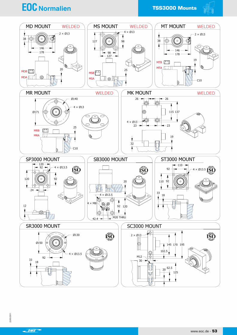
TSS3000 Mounts
TSS3000 Mounts
MDA
MDBMTA
MSA
MSB
MRA
MRB
4 × Ø13.5
18
4 × Ø13.5
145 170 195150 Ø
19
M1292
Ø130
32
62.5
125
2 × Ø13
30
26 26
3232
115 137
92 120
4 × Ø13.5
M20 THRU
20
4 × M8
4 × Ø13.5
146178
20
2 × Ø13
3898127
98127
25
4 × Ø13
146178
38
2 × Ø13
19
C10
MTB
Ø140
25
C10
171 Ø
4 × Ø13
92120
92
24
120
92110
92110
12
33
1833
102.5
20
4 × Ø13
.5.5
42.4
SHINWEON S&T CO.,LTD.
Copyright ⓒ2010 by SHINWEON S&T CO.,LTDAll Rights Reserved
www.shinweon.com TSS/55
NITROGEN GAS SPRING
MK MOUNT
MD MOUNT MS MOUNT MT MOUNTWELDED
WELDED
WELDED WELDED
MR MOUNT WELDED
SP3000 MOUNT SB3000 MOUNT ST3000 MOUNT
SR3000 MOUNT SC3000 MOUNT
22/0
3/20
11
22/0
3/20
11
54 - www.eoc.de
22/0
3/20
11
22/0
3/20
11
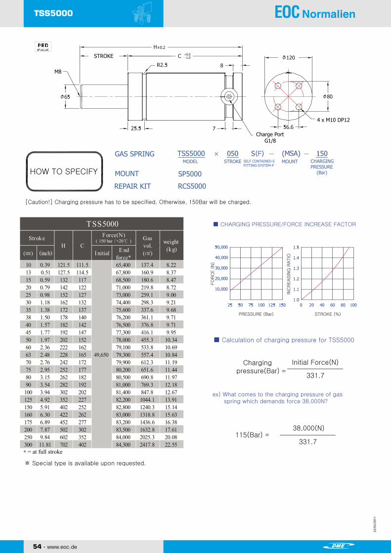
TSS5000
Charge Port G1/8
STROKE
M8
4 x M10 DP12
Copyright ⓒ2010 by SHINWEON S&T CO.,LTDAll Rights ReservedSHINWEON S&T CO.,LTD.
www.shinweon.com TSS/56
FO
RC
E (
N)
INC
REASIN
G R
ATIO
PRESSURE (Bar) STROKE (%)
Chargingpressure(Bar)
Initial Force(N)
331.7
115(Bar)38,000(N)
331.7
TSS5000 NITROGEN GAS SPRING
HOW TO SPECIFY
GAS SPRING
MOUNT
REPAIR KIT RCS5000
SP5000
MODEL STROKE SELF CONTAINED-SFITTING-SYSTEM-F
[Caution!] Charging pressure has to be specified. Otherwise, 150Bar will be charged.
TSS5000
■ CHARGING PRESSURE/FORCE INCREASE FACTOR
■ Calculation of charging pressure for TSS5000
ex) What comes to the charging pressure of gas spring which demands force 38,000N?
CHARGINGPRESSURE (Bar)
MOUNT
*= at full stroke
※ Special type is available upon requested.
10 0.39 121.5 111.5 65,400 137.4 8.2213 0.51 127.5 114.5 67,800 160.9 8.3715 0.59 132 117 68,500 180.6 8.4720 0.79 142 122 71,000 219.8 8.7225 0.98 152 127 73,000 259.1 9.0030 1.18 162 132 74,400 298.3 9.2135 1.38 172 137 75,600 337.6 9.6838 1.50 178 140 76,200 361.1 9.7140 1.57 182 142 76,500 376.8 9.7145 1.77 192 147 77,300 416.1 9.9550 1.97 202 152 78,000 455.3 10.3460 2.36 222 162 79,100 533.8 10.6963 2.48 228 165 79,300 557.4 10.8470 2.76 242 172 79,900 612.3 11.1975 2.95 252 177 80,200 651.6 11.4480 3.15 262 182 80,500 690.8 11.9790 3.54 282 192 81,000 769.3 12.18
100 3.94 302 202 81,400 847.8 12.67125 4.92 352 227 82,200 1044.1 13.91150 5.91 402 252 82,800 1240.3 15.14160 6.30 422 262 83,000 1318.8 15.63175 6.89 452 277 83,200 1436.6 16.38200 7.87 502 302 83,500 1632.8 17.61250 9.84 602 352 84,000 2025.3 20.08300 11.81 702 402 84,300 2417.8 22.55
weight(k g)
TSS5000
CH
49,650
Strok e Force(N) Gasvol.(㎤)
( 150 bar / +20℃ )
(㎜) (inch) I nitial E ndforce*

22/0
3/20
11
22/0
3/20
11
22/0
3/20
11
22/0
3/20
11
www.eoc.de - 55
TSS5000 Mounts
TSS5000 Mounts
MDA
MDBMTA
MSA
MSB
MRA
MRB
4 × Ø13.5
21
4 × Ø13.5
165 195 220175 Ø
19
M12109.5
Ø155
32
74
148
2 × Ø13
30
32 32
6262
146 174
109.5 140
20
4 × Ø13.5
165197
20
2 × Ø13
38114140
114140
25
4 × Ø13
165197
38
2 × Ø13
19
C10
MTB
Ø165
25
C10
197 Ø
4 × Ø17
109.5140
109.5
24
140
109.5130
109.5130
12
36
2136
115
20
4 × Ø17
.5.5
56.6M 0 THRU2
4 × M10 4 × Ø13.5
SHINWEON S&T CO.,LTD.
Copyright ⓒ2010 by SHINWEON S&T CO.,LTDAll Rights Reserved
www.shinweon.com TSS/57
NITROGEN GAS SPRING
MK MOUNT
MD MOUNT MS MOUNT MT MOUNTWELDED
WELDED
WELDED WELDED
MR MOUNT WELDED
SP5000 MOUNT SB5000 MOUNT ST5000 MOUNT
SR5000 MOUNT SC5000 MOUNT

22/0
3/20
11
22/0
3/20
11
TSL Series
SHINWEON S&T CO.,LTD.
NITROGEN GAS SPRING
CT02052E
TSP SERIES!TSP SERIES!
www.eoc.de

22/0
3/20
11
22/0
3/20
11
www.eoc.de - 57
TSL SeriesNITROGEN GAS SPRING TOSS GAS SPRING
■ General Specification
● Filling Materials ● Maximum Stroke Rate Per Minute (Recommended) Nitrogen GAs(N2) ~50 to 100 (at 20℃) ● Maximum Filling Pressure ● Piston Rod Speed 150~180 bar (at 20℃) 0.03~0.8 m/s
●Minimum Filling Pressure ● Rod Surface Treatment 25 bar (at 20℃) Nitrate Coating
● Operation Temperature ● Cylinder Surface Treatment -5 to 80℃ Oxidized Black Coating
● Pressure Increase as per Temperature
±0.3% / ℃
※ The above specification is subject to change without notice for performance improvement.
■ Specification
TYPE Stroke (mm)
CylinderDiameter Φ(mm)
Rod Φ(mm)
Initial Force (N)
End Force (N)
MAX.ChargingPressure
TSL0500
TSL0750
TSL1500
TSL3000
TSL5000
TSL7500
TSL10000
www.eoc.de

22/0
3/20
11
22/0
3/20
11
58 - www.eoc.de
22/0
3/20
11
22/0
3/20
11
TSL0500
2 x M8 DP6
Copyright ⓒ2010 by SHINWEON S&T CO.,LTDAll Rights ReservedSHINWEON S&T CO.,LTD.
www.shinweon.com TSL/60
TSL0500 NITROGEN GAS SPRING
HOW TO SPECIFY
GAS SPRING
MOUNT
REPAIR KIT RCL0500
SP0500
MODEL STROKE SELF CONTAINED-SFITTING-SYSTEM-F
[Caution!] Charging pressure has to be specified. Otherwise, 150Bar will be charged.
TSL0500
■ CHARGING PRESSURE/FORCE INCREASE FACTOR
■ Calculation of charging pressure for TSL0500
ex) What comes to the charging pressure of gas spring which demands force 4,000N?
FO
RC
E (
N)
INC
REASIN
G R
ATIO
PRESSURE (Bar) STROKE (%)
Chargingpressure(Bar)
Initial Force(N)
31.4
127(Bar)4,000(N)
31.4
Charge Port G1/8
CHARGINGPRESSURE (Bar)
M8
※ Special type is available upon requested.
*= at full stroke
10 0.39 105 95 5,100 33.9 0.8915 0.59 115 100 5,300 39.2 0.9420 0.79 125 105 5,400 44.6 0.9825 0.98 135 110 5,500 50.0 0.98 √30 1.18 145 115 5,600 55.3 1.1035 1.38 155 120 5,700 60.7 1.1338 1.50 161 123 5,700 63.9 1.1640 1.57 165 125 5,700 66.1 1.1645 1.77 175 130 5,800 71.5 1.1950 1.97 185 135 5,800 76.8 1.21 √60 2.36 205 145 5,900 87.6 1.2363 2.48 211 148 5,900 90.8 1.2570 2.76 225 155 6,000 98.3 1.3180 3.15 245 165 6,000 109.1 1.38 √90 3.54 265 175 6,100 119.8 1.45
100 3.94 285 185 6,100 130.6 1.51110 4.33 305 195 6,100 141.3 1.58120 4.72 325 205 6,200 152.1 1.64125 4.92 335 210 6,200 157.4 1.67160 6.30 405 245 6,200 195.1 1.89
4,650
H CWeight
(k g)
TSL 0500Strok e Force(N) Gas
vol.(㎤)
( 150 bar / +20℃ )
(㎜) (inch) I nitial E ndforce*
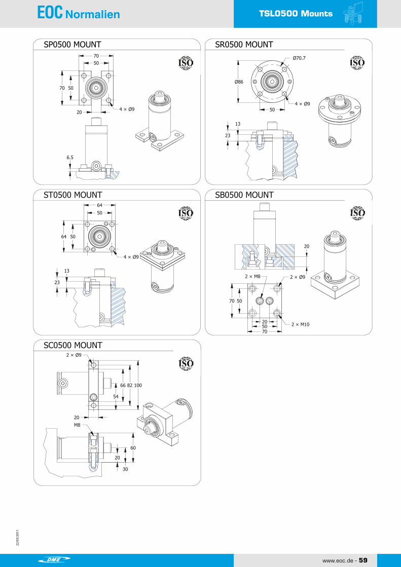
22/0
3/20
11
22/0
3/20
11
22/0
3/20
11
22/0
3/20
11
www.eoc.de - 59
TSL0500 Mounts
TSL0500 Mounts
13
23
86 Ø
50
Ø70.7
4 × Ø9
13
23
5064
4 × Ø9
66 82 100
20
30
60
20
2 × Ø9
M8
5070
5070
2 × Ø9
2 × M8
20
5070
5070
6.5
4 × Ø9
50
64
54
2 × M1020
20
SHINWEON S&T CO.,LTD.
Copyright ⓒ2010 by SHINWEON S&T CO.,LTDAll Rights Reserved
www.shinweon.com TSL/61
NITROGEN GAS SPRING
SP0500 MOUNT SR0500 MOUNT
ST0500 MOUNT
SC0500 MOUNT
SB0500 MOUNT

22/0
3/20
11
22/0
3/20
11
60 - www.eoc.de
22/0
3/20
11
22/0
3/20
11
TSL0750
2 x M8 DP12
STROKE
Charge Port G1/8
M8
Copyright ⓒ2010 by SHINWEON S&T CO.,LTDAll Rights ReservedSHINWEON S&T CO.,LTD.
www.shinweon.com
FO
RC
E (
N)
INC
REASIN
G R
ATIO
PRESSURE (Bar) STROKE (%)
Chargingpressure(Bar)
Initial Force(N)
49.1
122(Bar)6,000(N)
49.1
TSL0750 NITROGEN GAS SPRING
HOW TO SPECIFY
GAS SPRING
MOUNT
REPAIR KIT RCL0750
SP0750
MODEL STROKE SELF CONTAINED-SFITTING-SYSTEM-F
[Caution!] Charging pressure has to be specified. Otherwise, 150Bar will be charged.
TSL0750
■ CHARGING PRESSURE/FORCE INCREASE FACTOR
■ Calculation of charging pressure for TSL0750
ex) What comes to the charging pressure of gas spring which demands force 6,000N?
CHARGINGPRESSURE (Bar)
MOUNT
*= at full stroke
※ Special type is available upon requested.
TSL/62
10 0.39 115 105 8,400 40.2 1.3212.7 0.50 120.4 107.7 8,600 43.6 1.3415 0.59 125 110 8,700 46.5 1.3520 0.79 135 115 9,000 52.8 1.4025 0.98 145 120 9,300 59.0 1.44 √30 1.18 155 125 9,500 65.3 1.5035 1.38 165 130 9,700 71.6 1.5438 1.50 171 133 9,800 75.4 1.5840 1.57 175 135 9,800 77.9 1.5945 1.77 185 140 10,000 84.2 1.6450 1.97 195 145 10,100 90.4 1.68 √60 2.36 215 155 10,300 103.0 1.7863 2.48 222 158 10,300 106.8 1.8270 2.76 235 165 10,500 115.6 1.8775 2.95 245 170 10,500 121.8 1.9180 3.15 255 175 10,600 128.1 1.98 √90 3.54 275 185 10,700 140.7 2.06
100 3.94 295 195 10,800 153.2 2.14 √125 4.92 345 220 11,000 184.6 2.30 √150 5.91 395 245 11,100 216.0 2.61160 6.30 415 255 11,200 228.6 2.72 √175 6.89 445 270 11,200 247.4 2.84200 7.87 495 295 11,300 278.8 3.08250 9.84 595 345 11,500 341.6 3.60300 11.81 695 395 11,500 404.4 4.07
Weight(k g)
TSL 0750
H C
7,350
Strok e Force(N) Gasvol.(㎤)
( 150 bar / +20℃ )
(㎜) (inch) I nitial E ndforce*

22/0
3/20
11
22/0
3/20
11
22/0
3/20
11
22/0
3/20
11
www.eoc.de - 61
TSL0750 Mounts
TSL0750 Mounts
MDA
MDBMTA
MSA
MSB
MRA
MRB
4 × Ø9
13
4 × Ø9
90 110 13095 Ø
12.7
M856.5
Ø80
20
40
80
2 × Ø9
30
24 24
6171
68 89
20
4 × Ø9
89111
20
2 × Ø11
305476
5476
25
4 × Ø11
89111
30
2 × Ø11
19
C7
MTB
Ø90
19
C7
110 Ø
4 × Ø11
56.575
56.5
24
75
56.570
56.570
12
24
1324
70
20
4 × Ø11
2 × M87556.5
20
2 × Ø9
2 × M10
SHINWEON S&T CO.,LTD.
Copyright ⓒ2010 by SHINWEON S&T CO.,LTDAll Rights Reserved
www.shinweon.com TSL/63
NITROGEN GAS SPRING
MK MOUNT
MD MOUNT MS MOUNT MT MOUNTWELDED
WELDED
WELDED WELDED
MR MOUNT WELDED
SP0750 MOUNT SB0750 MOUNT ST0750 MOUNT
SR0750 MOUNT SC0750 MOUNT

22/0
3/20
11
22/0
3/20
11
62 - www.eoc.de
22/0
3/20
11
22/0
3/20
11
TSL1500
STROKE
Charge Port G1/8
4 x M8 DP12
M8
Copyright ⓒ2010 by SHINWEON S&T CO.,LTDAll Rights ReservedSHINWEON S&T CO.,LTD.
www.shinweon.com
FO
RC
E (
N)
INC
REASIN
G R
ATIO
PRESSURE (Bar) STROKE (%)
Chargingpressure(Bar)
Initial Force(N)
101.7
118(Bar)12,000(N)
101.7
TSL1500 NITROGEN GAS SPRING
HOW TO SPECIFY
GAS SPRING
MOUNT
REPAIR KIT RCL1500
SP1500
MODEL STROKE SELF CONTAINED-SFITTING-SYSTEM-F
[Caution!] Charging pressure has to be specified. Otherwise, 150Bar will be charged.
TSL1500
■ CHARGING PRESSURE/FORCE INCREASE FACTOR
■ Calculation of charging pressure for TSL1500
ex) What comes to the charging pressure of gas spring which demands force 12,000N?
CHARGINGPRESSURE (Bar)
MOUNT
*= at full stroke
※ Special type is available upon requested.
TSL/64
10 0.39 130 120 18,500 56.1 3.4013 0.51 135.4 122.4 19,100 63.6 3.4515 0.59 140 125 19,200 71.7 3.4820 0.79 150 130 19,700 87.2 3.5825 0.98 160 135 20,100 102.8 3.66 √30 1.18 170 140 20,400 118.4 3.7835 1.38 180 145 20,600 134.0 3.8638 1.50 186 148 20,700 143.3 3.9240 1.57 190 150 20,800 149.6 4.0045 1.77 200 155 20,900 165.1 4.0450 1.97 210 160 21,000 180.7 4.16 √60 2.36 230 170 21,200 211.9 4.3663 2.48 237 174 21,100 224.3 4.4070 2.76 250 180 21,400 243.0 4.4775 2.95 260 185 21,400 258.6 4.6080 3.15 270 190 21,500 274.2 4.67 √90 3.54 290 200 21,600 305.3 4.85
100 3.94 310 210 21,600 336.5 5.03 √125 4.92 360 235 21,800 414.4 5.47 √150 5.91 410 260 21,900 492.3 5.92160 6.30 430 270 21,900 523.4 6.22 √175 6.89 460 285 22,000 570.2 6.37200 7.87 510 310 22,000 648.1 6.82250 9.84 610 360 22,100 803.8 7.90300 11.81 710 410 22,100 959.6 8.68
H C
15,150
TSL 1500Strok e Force(N) Gas
vol.(㎤)
Weight(k g)
I nitial
( 150 bar / +20℃ )
E ndforce*
(㎜) (inch)

22/0
3/20
11
22/0
3/20
11
22/0
3/20
11
22/0
3/20
11
www.eoc.de - 63
TSL1500 Mounts
TSL1500 Mounts
MDA
MDBMTA
MSA
MSB
MRA
MRB
4 × Ø11
16
4 × Ø11
115 137 160122 Ø
19
M1073.5
Ø104
32
52.5
105
2 × Ø11
30
26 26
3232
95 118
73.5 100
4 × Ø11
M20 THRU
20
4 × M8
4 × Ø11
120152
20
2 × Ø13
3876102
76102
25
4 × Ø13
120152
38
2 × Ø13
19
C9
MTB
Ø120
19
C9
152 Ø
4 × Ø13
73.5100
73.5
24
100
73.590
73.590
12
29
1629
85
20
4 × Ø13
11
28.3
SHINWEON S&T CO.,LTD.
Copyright ⓒ2010 by SHINWEON S&T CO.,LTDAll Rights Reserved
www.shinweon.com TSL/65
NITROGEN GAS SPRING
MK MOUNT
MD MOUNT MS MOUNT MT MOUNTWELDED
WELDED
WELDED WELDED
MR MOUNT WELDED
SP1500 MOUNT SB1500 MOUNT ST1500 MOUNT
SR1500 MOUNT SC1500 MOUNT

22/0
3/20
11
22/0
3/20
11
64 - www.eoc.de
22/0
3/20
11
22/0
3/20
11
TSL3000
STROKE
Charge Port G1/8
4 x M8 DP12
M8
Copyright ⓒ2010 by SHINWEON S&T CO.,LTDAll Rights ReservedSHINWEON S&T CO.,LTD.
www.shinweon.com
FO
RC
E (
N)
INC
REASIN
G R
ATIO
PRESSURE (Bar) STROKE (%)
Chargingpressure(Bar)
Initial Force(N)
196.2
127(Bar)25,000(N)
196.2
TSL3000 NITROGEN GAS SPRING
HOW TO SPECIFY
GAS SPRING
MOUNT
REPAIR KIT RCL3000
SP3000
MODEL STROKE SELF CONTAINED-SFITTING-SYSTEM-F
[Caution!] Charging pressure has to be specified. Otherwise, 150Bar will be charged.
TSL3000
■ CHARGING PRESSURE/FORCE INCREASE FACTOR
■ Calculation of charging pressure for TSL3000
ex) What comes to the charging pressure of gas spring which demands force 25,000N?
CHARGINGPRESSURE (Bar)
MOUNT
*= at full stroke
※ Special type is available upon requested.
TSL/66
10 0.39 140 130 37,000 95.5 5.7413 0.51 145.5 132.5 38,500 108.0 5.8415 0.59 150 135 38,900 120.6 5.9220 0.79 160 140 40,200 145.7 6.0925 0.98 170 145 41,200 170.8 6.48 √30 1.18 180 150 42,000 195.9 6.5535 1.38 190 155 42,600 221.1 6.6238 1.50 196 158 42,900 236.1 6.7340 1.57 200 160 43,100 246.2 6.8045 1.77 210 165 43,600 271.3 6.9850 1.97 220 170 43,900 296.4 7.15 √60 2.36 240 180 44,500 346.7 7.5163 2.48 247 184 44,300 366.8 7.6870 2.76 260 190 44,900 396.9 7.8675 2.95 270 195 45,100 422.0 8.0480 3.15 280 200 45,300 447.1 8.27 √90 3.54 300 210 45,600 497.4 8.58
100 3.94 320 220 45,800 547.6 8.85 √125 4.92 370 245 46,200 673.2 9.65 √150 5.91 420 270 46,500 798.8 10.69160 6.30 440 280 46,600 849.1 11.05 √175 6.89 470 295 46,700 924.4 11.58200 7.87 520 320 46,900 1050.0 12.46250 9.84 620 370 47,200 1301.2 14.23300 11.81 720 420 47,300 1552.4 16.00
29,400
H CGasvol.(㎤)I nitial E nd
force*
Strok e Force(N)( 150 bar / +20℃ )
(㎜) (inch)
TSL 3000
Weight(k g)

22/0
3/20
11
22/0
3/20
11
22/0
3/20
11
22/0
3/20
11
www.eoc.de - 65
TSL3000 Mounts
TSL3000 Mounts
MDA
MDBMTA
MSA
MSB
MRA
MRB
4 × Ø13.5
18
4 × Ø13.5
145 170 195150 Ø
19
M1292
Ø130
32
62.5
125
2 × Ø13
30
26 26
3232
115 137
92 120
4 × Ø13.5
M20 THRU
20
4 × M8
4 × Ø13.5
146178
20
2 × Ø13
3898127
98127
25
4 × Ø13
146178
38
2 × Ø13
19
C10
MTB
Ø140
25
C10
171 Ø
4 × Ø13
92120
92
24
120
92110
92110
12
33
1833
102.5
20
4 × Ø13
.5.5
42.4
SHINWEON S&T CO.,LTD.
Copyright ⓒ2010 by SHINWEON S&T CO.,LTDAll Rights Reserved
www.shinweon.com TSL/67
NITROGEN GAS SPRING
MK MOUNT
MD MOUNT MS MOUNT MT MOUNTWELDED
WELDED
WELDED WELDED
MR MOUNT WELDED
SP3000 MOUNT SB3000 MOUNT ST3000 MOUNT
SR3000 MOUNT SC3000 MOUNT

22/0
3/20
11
22/0
3/20
11
66 - www.eoc.de
22/0
3/20
11
22/0
3/20
11
TSL5000
Charge Port G1/8
STROKE
4 x M10 DP12
M8
Copyright ⓒ2010 by SHINWEON S&T CO.,LTDAll Rights ReservedSHINWEON S&T CO.,LTD.
www.shinweon.com
FO
RC
E (
N)
INC
REASIN
G R
ATIO
PRESSURE (Bar) STROKE (%)
Chargingpressure(Bar)
Initial Force(N)
331.7
115(Bar)38,000(N)
331.7
TSL5000 NITROGEN GAS SPRING
HOW TO SPECIFY
GAS SPRING
MOUNT
REPAIR KIT RCL5000
SP5000
MODEL STROKE SELF CONTAINED-SFITTING-SYSTEM-F
[Caution!] Charging pressure has to be specified. Otherwise, 150Bar will be charged.
TSL5000
■ CHARGING PRESSURE/FORCE INCREASE FACTOR
■ Calculation of charging pressure for TSL5000
ex) What comes to the charging pressure of gas spring which demands force 38,000N?
CHARGINGPRESSURE (Bar)
MOUNT
*= at full stroke
※ Special type is available upon requested.
TSL/68
10 0.39 159.5 149.5 63,300 153.1 10.3213 0.51 165.5 152.5 65,600 176.6 10.7115 0.59 170 155 66,500 196.3 11.1020 0.79 180 160 69,100 235.5 11.4925 0.98 190 165 71,000 274.8 11.88 √30 1.18 200 170 72,600 314.0 12.2735 1.38 210 175 73,900 353.3 12.6638 1.50 216 178 74,500 376.8 13.0040 1.57 220 180 74,900 392.5 13.4445 1.77 230 185 75,800 431.8 13.8350 1.97 240 190 76,500 471.0 14.22 √60 2.36 260 200 77,800 549.5 14.6863 2.48 266 203 78,100 573.1 15.0770 2.76 280 210 78,700 628.0 15.4675 2.95 290 215 79,100 667.3 15.8580 3.15 300 220 79,400 706.5 16.24 √90 3.54 320 230 80,000 785.0 16.94
100 3.94 340 240 80,500 863.5 17.66 √125 4.92 390 265 81,400 1059.8 18.05 √150 5.91 440 290 82,100 1256.0 18.44160 6.30 460 300 82,300 1334.5 18.83 √175 6.89 490 315 82,600 1452.3 19.22200 7.87 540 340 83,000 1648.5 19.61250 9.84 640 390 83,500 2041.0 20.31300 11.81 740 440 83,900 2433.5 21.01
Weight(k g)
TSL 5000
CH(㎜) (inch)
Strok e Force(N) Gasvol.(㎤)
( 150 bar / +20℃ )
49,650
I nitial E ndforce*
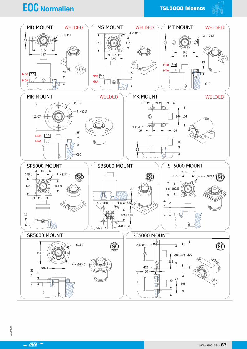
22/0
3/20
11
22/0
3/20
11
22/0
3/20
11
22/0
3/20
11
www.eoc.de - 67
TSL5000 Mounts
TSL5000 Mounts
MDA
MDBMTA
MSA
MSB
MRA
MRB
4 × Ø13.5
21
4 × Ø13.5
165 195 220175 Ø
19
M12109.5
Ø155
32
74
148
2 × Ø13
30
32 32
6262
146 174
109.5 140
4 × Ø13.5
M20 THRU
20
4 × M10
4 × Ø13.5
165197
20
2 × Ø13
38114140
114140
25
4 × Ø13
165197
38
2 × Ø13
19
C10
MTB
Ø165
25
C10
197 Ø
4 × Ø17
109.5140
109.5
24
140
109.5130
109.5130
12
36
2136
115
20
4 × Ø17
.5.5
56.6
SHINWEON S&T CO.,LTD.
Copyright ⓒ2010 by SHINWEON S&T CO.,LTDAll Rights Reserved
www.shinweon.com TSL/69
NITROGEN GAS SPRING
MK MOUNT
MD MOUNT MS MOUNT MT MOUNTWELDED
WELDED
WELDED WELDED
MR MOUNT WELDED
SP5000 MOUNT SB5000 MOUNT ST5000 MOUNT
SR5000 MOUNT SC5000 MOUNT
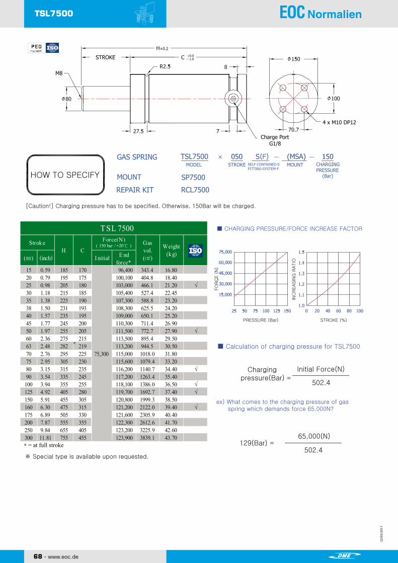
22/0
3/20
11
22/0
3/20
11
68 - www.eoc.de
22/0
3/20
11
22/0
3/20
11
TSL7500
Charge Port G1/8
STROKE
4 x M10 DP12
M8
Copyright ⓒ2010 by SHINWEON S&T CO.,LTDAll Rights ReservedSHINWEON S&T CO.,LTD.
www.shinweon.com
FO
RC
E (
N)
INC
REASIN
G R
ATIO
PRESSURE (Bar) STROKE (%)
Chargingpressure(Bar)
Initial Force(N)
502.4
129(Bar)65,000(N)
502.4
TSL7500 NITROGEN GAS SPRING
HOW TO SPECIFY
GAS SPRING
MOUNT
REPAIR KIT RCL7500
SP7500
MODEL STROKE SELF CONTAINED-SFITTING-SYSTEM-F
[Caution!] Charging pressure has to be specified. Otherwise, 150Bar will be charged.
TSL7500
■ CHARGING PRESSURE/FORCE INCREASE FACTOR
■ Calculation of charging pressure for TSL7500
ex) What comes to the charging pressure of gas spring which demands force 65,000N?
CHARGINGPRESSURE (Bar)
MOUNT
*= at full stroke
※ Special type is available upon requested.
TSL/70
Stroke
15 0.59 185 170 96,400 343.4 16.8020 0.79 195 175 100,100 404.8 18.4025 0.98 205 180 103,000 466.1 21.20 √30 1.18 215 185 105,400 527.4 22.4535 1.38 225 190 107,300 588.8 23.2038 1.50 231 193 108,300 625.5 24.2040 1.57 235 195 109,000 650.1 25.2045 1.77 245 200 110,300 711.4 26.9050 1.97 255 205 111,500 772.7 27.90 √60 2.36 275 215 113,500 895.4 29.5063 2.48 282 219 113,200 944.5 30.5070 2.76 295 225 115,000 1018.0 31.8075 2.95 305 230 115,600 1079.4 33.2080 3.15 315 235 116,200 1140.7 34.40 √90 3.54 335 245 117,200 1263.4 35.40
100 3.94 355 255 118,100 1386.0 36.50 √125 4.92 405 280 119,700 1692.7 37.40 √150 5.91 455 305 120,800 1999.3 38.50160 6.30 475 315 121,200 2122.0 39.40 √175 6.89 505 330 121,600 2305.9 40.40200 7.87 555 355 122,300 2612.6 41.70250 9.84 655 405 123,200 3225.9 42.60300 11.81 755 455 123,900 3839.1 43.70
Weight(k g)
TSL 7500
CH
75,300
Strok e ( 150 bar / +20℃ )Force(N) Gas
vol.(㎤)(㎜) (inch) I nitial E nd
force*

22/0
3/20
11
22/0
3/20
11
22/0
3/20
11
22/0
3/20
11
www.eoc.de - 69
TSL7500 Mounts
WELDEDMS MOUNT SB7500 MOUNT
SR7500 MOUNT
SP7500 MOUNT
ST7500 MOUNT
SHINWEON S&T CO.,LTD.
Copyright ⓒ2010 by SHINWEON S&T CO.,LTDAll Rights Reserved
www.shinweon.com TSL/71
NITROGEN GAS SPRING
SC7500 MOUNT
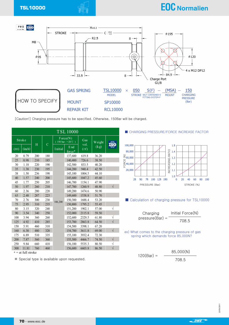
22/0
3/20
11
22/0
3/20
11
70 - www.eoc.de
22/0
3/20
11
22/0
3/20
11
TSL10000
Charge Port G1/8
STROKE
4 x M12 DP12
M8
Copyright ⓒ2010 by SHINWEON S&T CO.,LTDAll Rights ReservedSHINWEON S&T CO.,LTD.
www.shinweon.com
FO
RC
E (
N)
INC
REASIN
G R
ATIO
PRESSURE (Bar) STROKE (%)
Chargingpressure(Bar)
Initial Force(N)
708.5
120(Bar)85,000(N)
708.5
TSL10000 NITROGEN GAS SPRING
HOW TO SPECIFY
GAS SPRING
MOUNT
REPAIR KIT RCL10000
SP10000
MODEL STROKE SELF CONTAINED-SFITTING-SYSTEM-F
[Caution!] Charging pressure has to be specified. Otherwise, 150Bar will be charged.
TSL10000
■ CHARGING PRESSURE/FORCE INCREASE FACTOR
■ Calculation of charging pressure for TSL10000
ex) What comes to the charging pressure of gas spring which demands force 85,000N?
CHARGINGPRESSURE (Bar)
MOUNT
*= at full stroke
※ Special type is available upon requested.
TSL/72
20 0.79 200 180 137,600 619.8 36.2025 0.98 210 185 140,400 726.6 38.5030 1.18 220 190 142,500 833.5 40.2035 1.38 230 195 144,200 940.4 42.5038 1.50 236 198 145,100 1004.5 44.1040 1.57 240 200 145,600 1047.2 45.6045 1.77 250 205 146,700 1154.1 47.9050 1.97 260 210 147,700 1260.9 48.80 √60 2.36 280 220 149,200 1474.6 50.9063 2.48 287 223 149,600 1538.8 51.7070 2.76 300 230 150,300 1688.4 53.2075 2.95 310 235 150,800 1795.2 55.4580 3.15 320 240 151,200 1902.1 57.00 √90 3.54 340 250 152,000 2115.8 59.50
100 3.94 360 260 152,600 2329.5 61.80 √125 4.92 410 285 153,700 2863.8 64.50 √150 5.91 460 310 154,500 3398.1 67.20160 6.30 480 320 154,700 3611.8 69.00 √175 6.89 510 335 155,100 3932.4 72.30200 7.87 560 360 155,500 4466.7 74.50 √250 9.84 660 410 156,100 5535.3 80.50 √300 11.81 760 460 156,600 6603.8 86.50 √
Weight(k g)
TSL 10000
CH
106,200
( 150 bar / +20℃ )Strok e Force(N) Gasvol.(㎤)E nd
force*I nitial(㎜) (inch)

22/0
3/20
11
22/0
3/20
11
22/0
3/20
11
22/0
3/20
11
www.eoc.de - 71
TSL10000 Mounts
SHINWEON S&T CO.,LTD.
Copyright ⓒ2010 by SHINWEON S&T CO.,LTDAll Rights Reserved
www.shinweon.com TSL/73
NITROGEN GAS SPRING
WELDEDMS MOUNT SB10000 MOUNT
SP10000 MOUNT ST10000 MOUNT
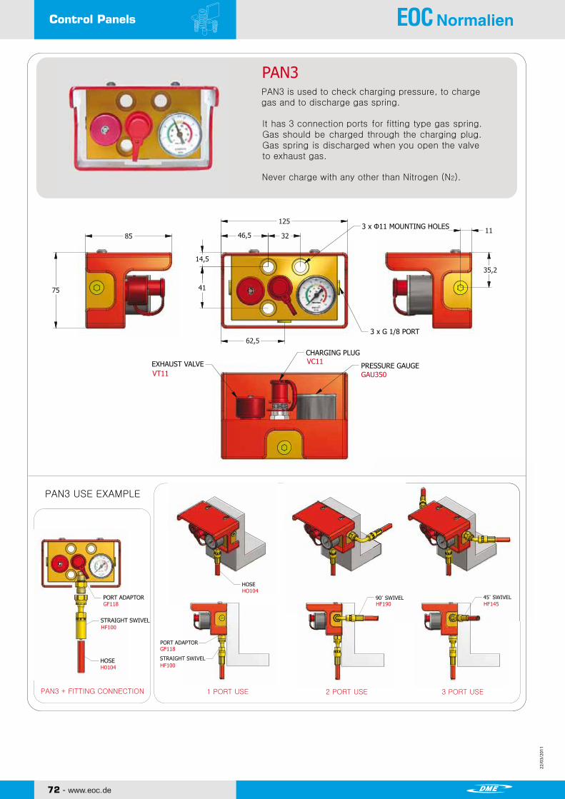
22/0
3/20
11
22/0
3/20
11
72 - www.eoc.de
22/0
3/20
11
22/0
3/20
11
Control Panels
PAN3 is used to check charging pressure, to charge gas and to discharge gas spring.
It has 3 connection ports for fitting type gas spring.Gas should be charged through the charging plug.Gas spring is discharged when you open the valveto exhaust gas.
Never charge with any other than Nitrogen (N2).
CONTROL PANEL NITROGEN GAS SPRING
Copyright ⓒ2010 by SHINWEON S&T CO.,LTDAll Rights ReservedSHINWEON S&T CO.,LTD.
www.shinweon.com 74
3 x Φ11 MOUNTING HOLES
3 x G 1/8 PORT
VT11
VC11
GAU350
PAN3 USE EXAMPLE
PORT ADAPTOR
STRAIGHT SWIVEL
HOSE
EXHAUST VALVE
CHARGING PLUG
PRESSURE GAUGE
HOSE
PORT ADAPTOR
STRAIGHT SWIVEL
90˚ SWIVEL 45˚ SWIVELGF118
HF100
H0104
HO104
GF118
HF100
HF190 HF145
PAN3 + FITTING CONNECTION 1 PORT USE 2 PORT USE 3 PORT USE
PAN3

22/0
3/20
11
22/0
3/20
11
22/0
3/20
11
22/0
3/20
11
www.eoc.de - 73
Control Panels
PAN6 USE EXAMPLE
SHINWEON S&T CO.,LTD.
Copyright ⓒ2010 by SHINWEON S&T CO.,LTDAll Rights Reserved
www.shinweon.com 75
NITROGEN GAS SPRING CONTROL PANEL
7512
PAN6
52
106 7
42,5 4523
130
4 x Ø7MOUNTING HOLES
6,25
VC11
PRESSURE GAUGEGAU350
VT11
PORT ADAPTORCF111
HOSEHO055
STRAIGHT SWIVELCF100
ELBOW PORT ADAPTORCF090
12 x M6 PORT
PORT ADAPTORCF111
STRAIGHT SWIVELCF100
HOSEHO055
PAN6 is CONTROL PANEL for COMPACT FITTING.
It is used to check charging pressure, to charge and to discharge gas spring.
Never charge with any other than Nitrogen (N2).
CHARGING PLUG
EXHAUST VALVE
PAN6 + FITTING CONNECTION VERTICALITY FIX 5 PORT USE VERTICALITY FIX 7 PORT USE HORIZONTALITY FIX 7 PORT USE

22/0
3/20
11
22/0
3/20
11
74 - www.eoc.de
22/0
3/20
11
22/0
3/20
11
Multi Panel
CHARGINGCHARGING
Copyright ⓒ2010 by SHINWEON S&T CO.,LTDAll Rights ReservedSHINWEON S&T CO.,LTD.
www.shinweon.com 76
NITROGEN GAS SPRINGMULTI PANEL
PSS SERIESPSS MULTI PANEL is used when singlemold needs multiple pressures.
Depends on model, it can be used from2 lines to 8 lines of different pressure asa customer needs.
PSS-2PSS-3PSS-4PSS-5PSS-6PSS-7PSS-8
4 x Φ9 MOUNTING HOLES
OPTIONAL PORT
MAIN EXHAUST VALVE
LINE EXHAUST VALVE
COVER
PRESSURE GAUGECHARGING PLUG
G 1/8
VT11
VT11
VC11 GAU350
HOW TO SPECIFY
PSSMULTI PANEL Line
PSS USE EXAMPLE
HOW TO SPECIFY
PORT ADAPTOR
STRAIGHT SWIVEL
HOSE
GF118
HF100
HO104
PSS-3 + FITTING CONNECTION
L I N E
VERTICALITY FIX PORT USE HORIZONTALITY FIX PORT USE
HOSE
PORT ADAPTOR
STRAIGHT SWIVEL
GF118
HO104
HF100
MODEL
PSS-2
PSS-3
PSS-4
PSS-5
PSS-6
PSS-7
PSS-8
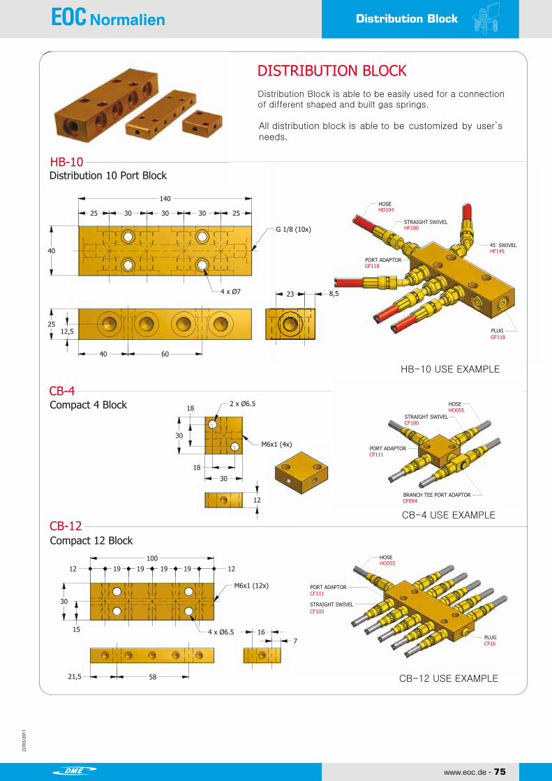
22/0
3/20
11
22/0
3/20
11
22/0
3/20
11
22/0
3/20
11
www.eoc.de - 75
Distribution Block
Distribution Block is able to be easily used for a connectionof different shaped and built gas springs.
DISTRIBUTION BLOCK
SHINWEON S&T CO.,LTD.
Copyright ⓒ2010 by SHINWEON S&T CO.,LTDAll Rights Reserved
www.shinweon.com 77
DISTRIBUTION BLOCKNITROGEN GAS SPRING
All distribution block is able to be customized by user’sneeds.
HB-10Distribution 10 Port Block
G 1/8 (10x)
HOSE
STRAIGHT SWIVEL
PORT ADAPTOR
45˚ SWIVEL
PLUG
Compact 4 Block
Compact 12 Block
HOSE
STRAIGHT SWIVEL
PORT ADAPTOR
BRANCH TEE PORT ADAPTOR
HOSE
PORT ADAPTOR
STRAIGHT SWIVEL
PLUG
CB-4
CB-12CB-4 USE EXAMPLE
HO055
CF111
CF100
CP16
CB-12 USE EXAMPLE
HB-10 USE EXAMPLE
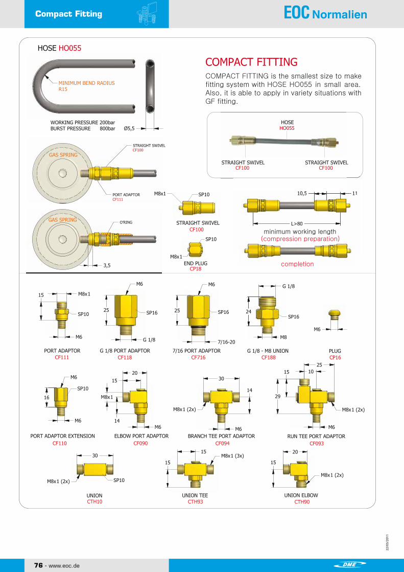
22/0
3/20
11
22/0
3/20
11
76 - www.eoc.de
22/0
3/20
11
22/0
3/20
11
Compact Fitting
Copyright ⓒ2010 by SHINWEON S&T CO.,LTDAll Rights ReservedSHINWEON S&T CO.,LTD.
www.shinweon.com 78
NITROGEN GAS SPRINGCOMPACT FITTING
COMPACT FITTINGCOMPACT FITTING is the smallest size to makefitting system with HOSE HO055 in small area.Also, it is able to apply in variety situations withGF fitting.
MINIMUM BEND RADIUSR15
WORKING PRESSURE 200barBURST PRESSURE 800bar
STRAIGHT SWIVEL
PORT ADAPTOR
STRAIGHT SWIVEL
END PLUG
O’RING
minimum working length(compression preparation)
completion
PORT ADAPTOR G 1/8 PORT ADAPTOR 7/16 PORT ADAPTOR G 1/8 - M8 UNION PLUG
PORT ADAPTOR EXTENSION ELBOW PORT ADAPTOR BRANCH TEE PORT ADAPTOR RUN TEE PORT ADAPTOR
UNION UNION TEE UNION ELBOW
CF100 CF100STRAIGHT SWIVEL STRAIGHT SWIVEL
HOSE
GAS SPRING
GAS SPRING
CF100
CF111
CF100
CP18
CF111 CF118 CF716 CF188 CP16
CF110 CF090 CF094 CF093
CTH10 CTH93 CTH90

22/0
3/20
11
22/0
3/20
11
22/0
3/20
11
22/0
3/20
11
www.eoc.de - 77
GF Fitting
UNION UNION TEEHTH10 HTH93
SHINWEON S&T CO.,LTD.
Copyright ⓒ2010 by SHINWEON S&T CO.,LTDAll Rights Reserved
www.shinweon.com 79
NITROGEN GAS SPRING GF FITTING
GF FITTINGGF FITTING is the most common fitting systemby using HOSE HO104. It can be installed infitting system by variety combinations.
MINIMUM BEND RADIUSR30
WORKING PRESSURE 200barBURST PRESSURE 700bar
GAS SPRING
GAS SPRING
PORT ADAPTOR STRAIGHT SWIVEL
HOSE
45˚ SWIVEL
STRAIGHT SWIVEL
90˚ SWIVEL
FITTING + HOSE USE EXAMPLE
FITTING + HOSE Combination Cross-Section View
O’ RING
PORT ADAPTOR PORT ADAPTOR PLUG PLUG END PLUG
SWIVEL NUT BRANCH TEE SWIVEL NUT RUN TEE 90˚ SWIVEL NUT ELBOW
UNION CROSS UNION ELBOWHTH94 HTH90
GF118 GF111 GP118 GP716 GP100
FS094 FS093 FS090
HF100
HF145
HF190
HO104
HF100GF118

22/0
3/20
11
22/0
3/20
11
78 - www.eoc.de
22/0
3/20
11
22/0
3/20
11
VF Fitting
UNION UNION TEEVTH10 VTH93
UNION CROSS UNION ELBOWVTH94 VTH90
VF100
VF145
VF190
45˚ SWIVEL
90˚ SWIVEL
STRAIGHT SWIVEL
VF FITTING with HOSE HO104 is fitting system that
uses a connection of surface contact withoutsealing . It can be installed in fitting system bycombinations.
Copyright ⓒ2010 by SHINWEON S&T CO.,LTDAll Rights ReservedSHINWEON S&T CO.,LTD.
www.shinweon.com 80
VF FITTING NITROGEN GAS SPRING
VF FITTINGSTRAIGHT SWIVEL
PORT ADAPTOR
HOSEVF100
HO104
VG111
GAS SPRING
GAS SPRING
PORT ADAPTORVG111
7/16-20-UNF
7/16-20-UNF
45˚ SWIVEL NUT ELBOW SWIVEL NUT BRANCH TEE SWIVEL NUT RUN TEE 90˚ SWIVEL NUT ELBOWVS045 VS094 VS093 VS090
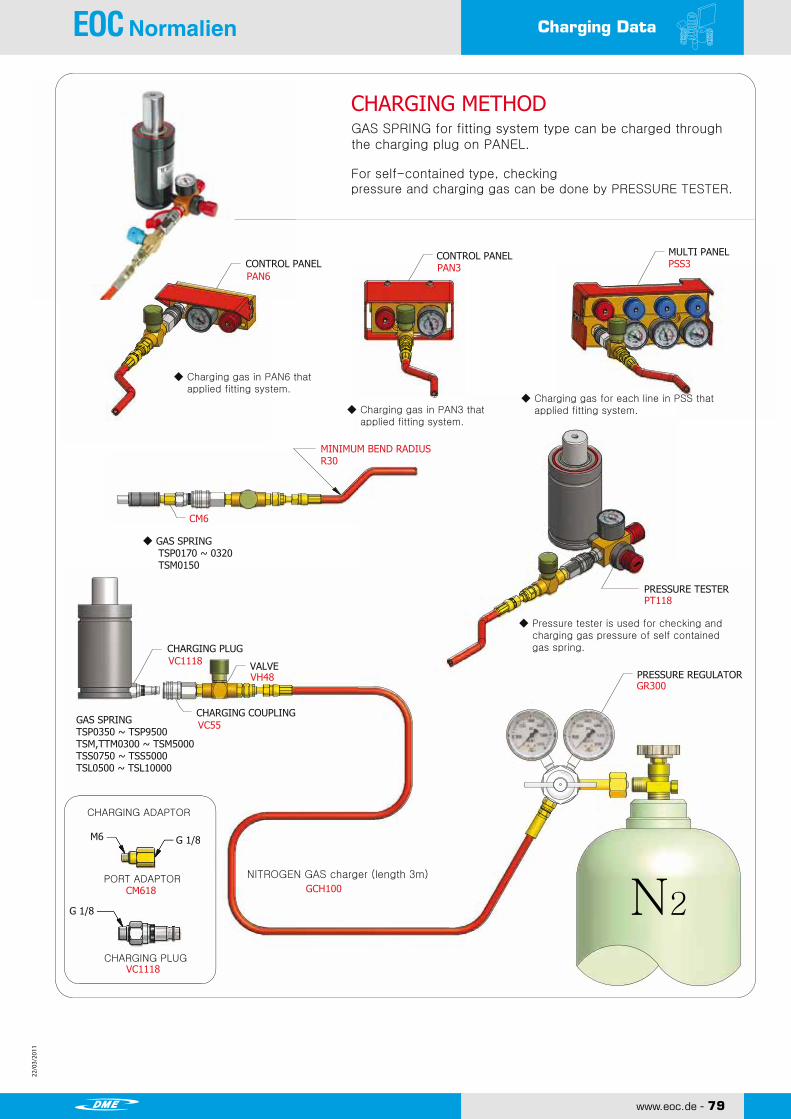
22/0
3/20
11
22/0
3/20
11
22/0
3/20
11
22/0
3/20
11
www.eoc.de - 79
Charging Data
GAS SPRING for fitting system type can be charged throughthe charging plug on PANEL.
CHARGING METHOD
SHINWEON S&T CO.,LTD.
Copyright ⓒ2010 by SHINWEON S&T CO.,LTDAll Rights Reserved
www.shinweon.com 81
NITROGEN GAS SPRING CHARGING DATA
For self-contained type, checkingpressure and charging gas can be done by PRESSURE TESTER.
CONTROL PANELCONTROL PANEL MULTI PANEL
PAN6PAN3 PSS3
MINIMUM BEND RADIUSR30
CM6
PRESSURE TESTER
PRESSURE REGULATOR
NITROGEN GAS charger (length 3m)
GCH100
VC1118
VH48
VC55
CHARGING PLUG
VALVE
CHARGING COUPLINGGAS SPRINGTSP0350 ~ TSP9500TSM,TTM0300 ~ TSM5000TSS0750 ~ TSS5000TSL0500 ~ TSL10000
CHARGING ADAPTOR
PORT ADAPTOR
CHARGING PLUG
CM618
VC1118
◆ GAS SPRING TSP0170 ~ 0320 TSM0150
◆ Charging gas in PAN6 that applied fitting system.
◆ Charging gas in PAN3 that applied fitting system.
◆ Charging gas for each line in PSS that applied fitting system.
◆ Pressure tester is used for checking and charging gas pressure of self contained gas spring.
PT118
GR300
N2

22/0
3/20
11
22/0
3/20
11
80 - www.eoc.de
22/0
3/20
11
22/0
3/20
11
Accumulator
2 PORT USE
By connection with fitting system, EOC ACCUMULATORkeeps constant pressure level by minimize the differencebetween initial pressure and final pressure.
NITROGEN GAS SPRINGACCUMULATOR
PRESSURE DISTRIBUTION TANK
※ The formula for pressure ratio of EOC Accumulator System is seen on page 89.
HOW TO SPECIFY
HOW TO SPECIFY
Accumulator Specification
ACCUMULATOR USE EXAMPLE
PORT ADAPTOR
STRAIGHT SWIVEL
HOSE
ACCUMULATOR + FITTING CONNECTION
GF118
HF100
HO104
GF118HO104
HF100
PORT ADAPTORHOSE
STRAIGHT SWIVEL
4 PORT USE
TAN
DESCRIPTIONVOLUME
㎤
TAN050-25
TAN050-50
TAN050-75
TAN080-25
TAN080-50
TAN080-75
TAN125-25
TAN125-50
TAN125-75
TAN210-25
TAN210-50
8 x G 1/8

22/0
3/20
11
22/0
3/20
11
22/0
3/20
11
22/0
3/20
11
www.eoc.de - 81
Hose ManualHOSE MANUAL
SHINWEON S&T CO.,LTD.
Copyright ⓒ2010 by SHINWEON S&T CO.,LTDAll Rights Reserved
www.shinweon.com 83
NITROGEN GAS SPRING
GF FITTING + HO104 HOSE CONNECTION
COMPACT FITTING + HO055 HOSE CONNECTION
GF FITTING
SWIVEL Compression Cross-Section View
COMPACT FITTING
SWIVEL Compression Cross-Section View
STRAIGHT STRAIGHT
GF FITTING + HOSE HO104 application
COMPACT FITTING + HOSE HO055 application
Com
pre
ssio
n P
repara
tion
Com
pre
ssio
n C
om
ple
tion
Com
pre
ssio
n P
repara
tion
Com
pre
ssio
n C
om
ple
tion
◆ Fitting System Type GAS SPRING Example
STRAIGHT
TORSION
INTERFERENCE
FITTING Combination Cross-Section View
HOSE CLAMP
Use for fixing hose. HCL06HOSE_ HO055 Fixing
HCL10HOSE_ HO104 Fixing
HCL48HOSE_ HO104 Fixing
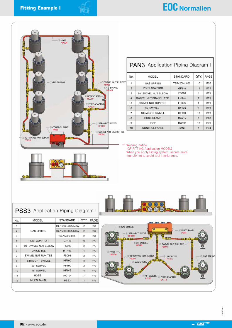
22/0
3/20
11
22/0
3/20
11
82 - www.eoc.de
22/0
3/20
11
22/0
3/20
11
Fitting Example I
Copyright ⓒ2010 by SHINWEON S&T CO.,LTDAll Rights ReservedSHINWEON S&T CO.,LTD.
www.shinweon.com 84
FITTING EXAMPLE I NITROGEN GAS SPRING
Application Piping Diagram IPAN3
MODEL STANDARD QTY. PAGE
GAS SPRING
PORT ADAPTOR
90˚ SWIVEL NUT ELBOW
SWIVEL NUT BRANCH TEE
SWIVEL NUT RUN TEE
45˚ SWIVEL
STRAIGHT SWIVEL
HOSE CLAMP
HOSE
CONTROL PANEL
GF118
FS090
FS094
FS093
HF145
HF100
HCL10
HO104
PAN3
Working notice(GF FITTING Application MODEL)When you apply Fitting system, secure morethan 20mm to avoid tool interference.
Application Piping Diagram IPSS3
No.
No. MODEL STANDARD QTY. PAGE
GAS SPRING
PORT ADAPTOR
90˚ SWIVEL NUT ELBOW
UNION TEE
SWIVEL NUT RUN TEE
STRAIGHT SWIVEL
45˚ SWIVEL
90˚ SWIVEL
HOSE
MULTI PANEL
TSL1500 x 025-MSA
TSL1500 x 025-MDA
TSL1500 x 025
GF118
FS090
HTH93
FS093
HF100
HF190
HF145
HO104
PSS3
HOSE
GAS SPRING SWIVEL NUT RUN TEE
45˚ SWIVEL
HOSE CLAMP
PORT ADAPTOR
STRAIGHT SWIVEL
SWIVEL NUT BRANCH TEE
CONTROL PANEL
90˚ SWIVEL NUT ELBOW
GAS SPRING
STRAIGHT SWIVEL
90˚ SWIVEL
90˚ SWIVEL NUT ELBOW
SWIVEL NUT RUN TEE
GAS SPRING
GAS SPRING
HOSE
45˚ SWIVEL PORT ADAPTOR
MULTI PANEL
UNION TEE
HO104
FS093
HF145
HCL10
GF118
HF100
FS094
PAN3
FS090
HF100PSS3
GF118HF145
HO104
FS090
HF190 FS093
HTH93
TSP4200 x 060
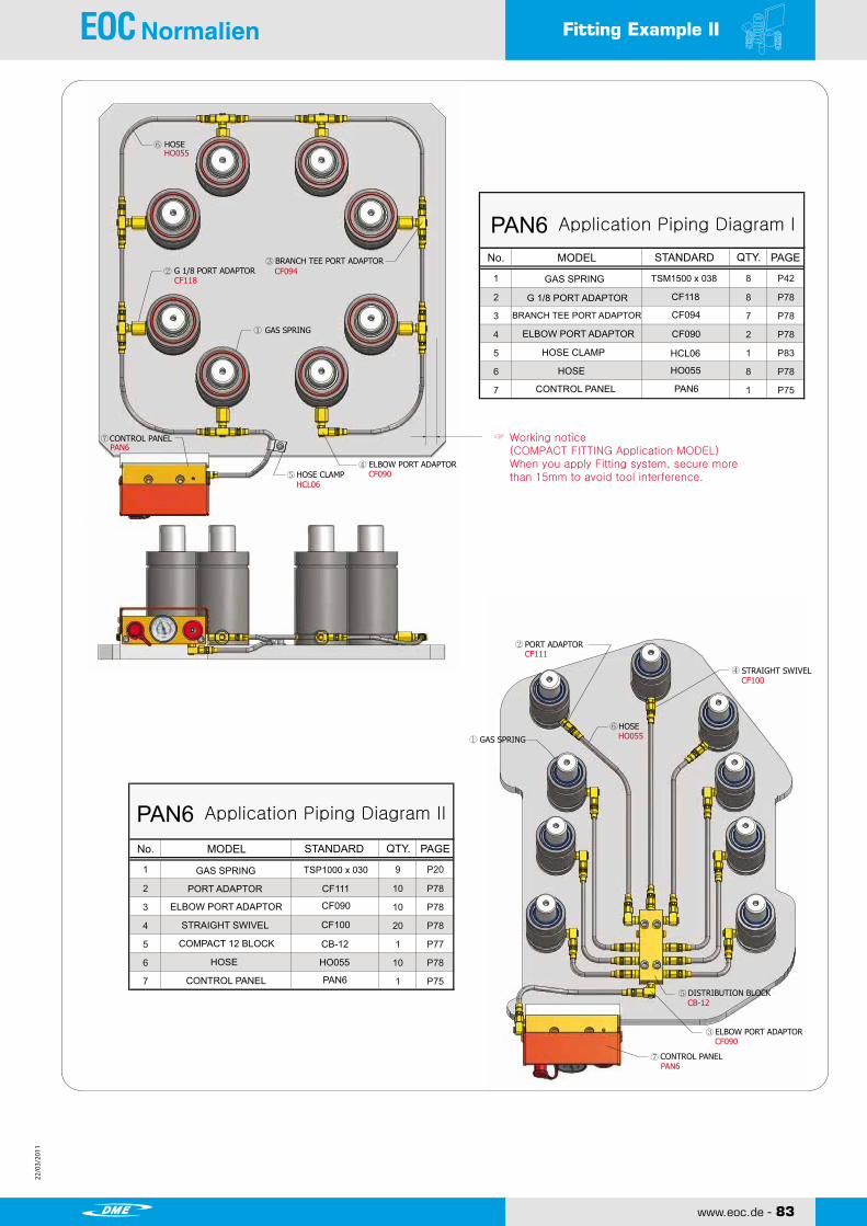
22/0
3/20
11
22/0
3/20
11
22/0
3/20
11
22/0
3/20
11
www.eoc.de - 83
Fitting Example II
Working notice(COMPACT FITTING Application MODEL)When you apply Fitting system, secure morethan 15mm to avoid tool interference.
TSM1500 x 038
FITTING EXAMPLE II
SHINWEON S&T CO.,LTD.
Copyright ⓒ2010 by SHINWEON S&T CO.,LTDAll Rights Reserved
www.shinweon.com 85
NITROGEN GAS SPRING
Application Piping Diagram IPAN6MODEL STANDARD QTY. PAGENo.
GAS SPRING
G 1/8 PORT ADAPTOR
BRANCH TEE PORT ADAPTOR
ELBOW PORT ADAPTOR
HOSE CLAMP
HOSE
CONTROL PANEL
Application Piping Diagram IIPAN6MODEL STANDARD QTY. PAGENo.
GAS SPRING
PORT ADAPTOR
ELBOW PORT ADAPTOR
STRAIGHT SWIVEL
COMPACT 12 BLOCK
HOSE
CONTROL PANEL
TSP1000 x 030
CF118
CF094
CF090
HCL06
HO055
PAN6
CF111
CF090
CF100
CB-12
HO055
PAN6
HOSE
GAS SPRING
BRANCH TEE PORT ADAPTORG 1/8 PORT ADAPTOR
ELBOW PORT ADAPTORHOSE CLAMP
CONTROL PANEL
STRAIGHT SWIVEL
PORT ADAPTOR
GAS SPRING
HOSE
ELBOW PORT ADAPTOR
DISTRIBUTION BLOCK
CONTROL PANEL
HO055
CF118CF094
HCL06CF090
PAN6
CF111
CF100
HO055
CB-12
CF090
PAN6

22/0
3/20
11
22/0
3/20
11
84 - www.eoc.de
22/0
3/20
11
22/0
3/20
11
Charging Accessories
KARRYKRIMP ASSEMBLING TOOL
GAS BOOSTERS HOSE ASSEMBLY
HOSE SCISSORS PRESSURE TESTER
CHARGING COUPLING CHARGING PLUG
HK8201 MARK10
S86JN GCH100(Length:3m)
HS10 PT118 (G1/8 type)PT716 (7/16 type)
VC55 VC1118 (G 1/8)VC11716 (7/16)
Standard) HK8201 Standard) MARK10
Standard) S86JN Standard) GCH100
Standard) HS10 Standard) PT118
Standard) VC55 Standard) VC1118
ㆍHO104 Hose & Swivel hose adaptor pressesㆍKARRYKRIMP can combine HO104 Hose & Swivel hose adaptor Hose.
ㆍHO055 Hose & Straight Swivel pressesㆍAssembling tool can combine HO055 Hose and Straight Swivel.ㆍIt is easy to carry, so suitable for moving around work place.
ㆍGas booster increases gas pressure ratio to user’s setting during charging gas of fitting
Pressure ratio (30:1)
ㆍCharging Hose System
ㆍHose Cutter ㆍCross Pressure Tester ㆍPortable pressure tester is used for controlling and charging pressure of self contained type.ㆍPlease select correct model which fits to product.
ㆍCharging Female Coupling ㆍIt combined with charging plug to charge gas.
ㆍCharging Male PlugㆍIt combined with charging coupling to charge gas.

22/0
3/20
11
22/0
3/20
11
22/0
3/20
11
22/0
3/20
11
www.eoc.de - 85
Repair Tools
COMPACT LOAD CELL DIGITAL LOAD CELL
VALVE TIGHTEN TOOL VALVE CONTROL TOOL
STOPRING REMOVAL TOOL T-REMOVAL TOOL
PRESSURE GAUGE VALVE
CLC
VTT26R
GAU350
SRT42 (0350~4200)SRT50 (5000~10000)
DLE10
VCT06(M6 type)
TRT06(M6 type)TRT08 (M8 type)
CV100
VCT18(G 1/8 type)
Standard) CLC1500 Standard) DLE10
Standard) VTT26R Standard) VCT06
Standard) SRT42 Standard) TRT06
Standard) GAU350 Standard) CV100
Standard
ㆍGas pressure gaugeㆍIt measures accurate pressure by placing on product.ㆍPlease select correct model which fits to product
ㆍTorque Driver ㆍUsed for assembly or disassembly of valve.ㆍAvoiding break a valve by Over Torque.
ㆍUsed to remove gas during disassembly gas spring.ㆍStopring can be removed by stopring removal tool after using valve control tool.ㆍPlease select correct model which fits product.
ㆍCompact Pressure Gauge
ㆍDigital load checking gaugeㆍIt measures load by placing gas spring on the gauge.
ㆍGas Control ToolㆍUsed for exhausting gas during disassembly gas spring.ㆍPlease select correct model which fits product.
ㆍGas Spring Disassembly Tool ㆍSequence ① Remove the gas to valve control tools ② Remove the ring by using the Stopring Removal Tool. ③ Isolates the Rod Ass’y from the cylinder using the T-Removal Tool.ㆍPlease select correct model which fits product.
ㆍCheck ValveㆍWhen you change fitting system type gas spring to self-contained type, you can assemble or disassemble with valve tighten tool.
ㆍUnit - bar (0~350) - Mpa (0~35)
ㆍLoad Range - 0 ~ 10t (0 ~1 00kN)
ㆍUnit - bar (0~350) - Mpa (0~35)
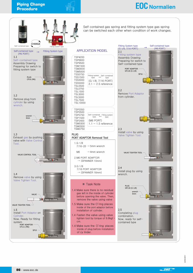
22/0
3/20
11
22/0
3/20
11
86 - www.eoc.de
22/0
3/20
11
22/0
3/20
11
Piping Change Procedure
Copyright ⓒ2010 by SHINWEON S&T CO.,LTDAll Rights ReservedSHINWEON S&T CO.,LTD.
www.shinweon.com 88
PIPING CHANGE PROCEDURE NITROGEN GAS SPRING
Self contained gas spring and fitting system type gas springcan be switched each other when condition of work changes.
Self-contained type Fitting System type
Self-contained typeAssembly DrawingPreparing for switch tofitting system type
Remove plug fromcylinder by usingwrench.
Exhaust gas by pushingvalve with Valve ControlTool.
Remove valve by using Valve Tighten Tool.
Install Port Adaptor onCylinder.Now, Ready for fittingsystem
Fitting system typeAssembly DrawingPreparing for switch toSelf-contained type
Remove Port Adaptorfrom cylinder.
Install valve by usingValve Tighten Tool.
Install plug by usingwrench.
Completing plugcombination.Now, ready for self-contained type
APPLICATION MODEL
PLUGPORT ADAPTOR Removal Tool
Self-contained type (M6 PORT)
Fitting System type
Fitting System type(G 1/8, 7/16 PORT)
Self-contained type (M6 PORT)
Fitting system type
Self-contained type
Self-contained type
Fitting system type
※ Task Note
1.4 Make sure there is no residual gas left in the inside of cylinder before opening the valve. Then, remove the valve using valve
1.5 Make sure the O’ring places inside of the port adaptor before installation of cylinder.
1.4 Fasten the valve using valve tighten tool by torque of 9.8kgfㆍ cm.
1.4 Make sure the O’ring places inside of plug before installation of cy linder.
TSP4200TSP6600TSP9500TSM1500TSM3000TSM5000TSS0750TSS1500TSS3000TSS5000TSL0500TSL0750
TSL3000TSL5000
TSL1500
TSL7500TSL10000
TSP0350TSP0500TSP0750TSP1500TSP2400TSM0300TSM0500TSM0750
1.G 1/8
7/16-20 5mm wrench
M6 4mm wrench
M6 PORT ADAPTOR
(SPANNER 10mm)
3.G 1/87/16 PORT ADAPTOR
(SPANNER 16mm)
PLUGCP16 (M6)
wrench4mm
VALVE CONTROL TOOL
VALVE
VALVE TIGHTEN TOOL
PORT ADAPTORCF111 (M6)
SP10
PORT ADAPTORGF118 (G 1/8)
SP16
VALVE TIGHTEN TOOL
wrench5mm
PLUGGP118 (G 1/8)
(G 1/8, 7/16 PORT)2.1 ~ 2.5 reference
(M6 PORT)1.1 ~ 1.5 reference
CHANGE

22/0
3/20
11
22/0
3/20
11
22/0
3/20
11
22/0
3/20
11
www.eoc.de - 87
Technical DataTECHNICAL DATATECHNICAL DATANITROGEN GAS SPRING
■ Calculation of Pressure Ratio
■ Calculation of Accumulator applied
■ Initial force gradient due to temperature
EX) What is the pressure ratio when 50mm of stroke is applied with EOC GAS SPRING TSS5000 x 60?
F = Pressure RatioVa = Volume of Accumulator(㎠)Vg = Volume of Gas Spring(㎠)n = Numbers of Gas SpringS = Real Used Stroke(㎝)R = Cross Section of piston Rod(㎠)
EX) What is pressure ratio when 50mm of stroke is applied with 12 of EOC GAS SPRING TSS 5000 x 60 and 2 of Accumulators TAN080-75?
Volume increases as temperature increases, and volume decreasesas temperature decreases. (PV = RT)
With constant pressure volume of any gas increases 1/273 by incrementof 1℃ from 0℃ of temperature (Charles’s Law).
Initial temperature Final temperature
Pressure is proportional to the force
EX) At 20℃, what is force of gas spring if temperature of gas spring (initial force of 7,350N) is increased by 50℃ during operation?
absolute (K) = ℃ + 273

22/0
3/20
11
22/0
3/20
11
88 - www.eoc.de
22/0
3/20
11
22/0
3/20
11
Technical DataNITROGEN GAS SPRINGTECHNICAL DATATECHNICAL DATA
■ Calculation of Pressure Ratio
※ Weight conversion of Nitrogen gas
(Ideal gas equation)
P = PressureV = Volumen = Number of molR = Ideal gas constantT = Absolute temperature
※ Molecular weight of Nitrogen M = 28.0134 Volume of Nitrogen gas 1mol = 22.4 Liter
EX) When you apply fitting system with 6 of EOC GAS SPRING TSM1500 x 60 and 10 of TSM5000 x 80, what is amount of nitrogen gas to be charged?
Specifications : Nitrogen gas charging pressure 120bar 35℃) Cyilnder Volume (40.1 Liter)
Standard : Volume of TSM1500 x 60 = 205.6 ㎤ Volume of TSM1500 x 80 = 675.1㎤
Charging Pressure: 150 bar (20℃)
(Number of mol) (Molecular Weight of Nitrogen)
(Number of mol) (Molecular Weight of Nitrogen)
(actually using gas)
Ex) When you apply fitting system with 6 of EOC GAS SPRING TSM1500 x 60 and 10 of TSM5000 x 80, what is amount of nitrogen gas to be charged?
= If amount of charge in fitting line and Panel and actual using gas are considered as 50%, 40.1 Liter bomb can use 1.4 times with each 7.98Liter.
(Number of mol) (Molecular Weight of Nitrogen)

22/0
3/20
11
22/0
3/20
11
22/0
3/20
11
22/0
3/20
11
www.eoc.de - 89
Info
Ex.MODEL TSP1000 X 050 Ex.MODEL TSM0750 X 050
Ex.MODEL TSS0750 X 050 Ex.MODEL TSL0750 X 050
TSP Series TSM Series
TSS Series TSL Series
XTRA HIGH POWER COMPACT TYPE
TSS STANDARD ISO STANDARD
Stroke (mm)Model
RodΦ(mm)
Cylinder Φ(mm)
InitialForce (N)
Stroke (mm)
RodΦ(mm)
Cylinder Φ(mm)
InitialForce (N)
Model
Stroke (mm)Model
RodΦ(mm)
Cylinder Φ(mm)
InitialForce (N)
Stroke (mm)
RodΦ(mm)
Cylinder Φ(mm)
InitialForce (N)
Model
TSP0170TSP0320TSP0350TSP0500TSP0750TSP1000TSP1500TSP2400TSP4200TSP6600TSP9500
TSM0150TSM0300TSM0500TSM0750TSM1500TSM3000TSM5000
TSS0750TSS1500TSS3000TSS5000
TSL0500TSL0750TSL1500TSL3000TSL50000TSL75000TSL10000
90 - www.eoc.de

GENERAL CONDITIONS OF SALE DME EUROPE
1. CONCLUSION OF CONTRACT - APPLICATION The contract is validly entered into and the order is accepted after written confirmation by seller. These sales conditions apply to the exclusion of any other terms or conditions, unless expressly accepted in writing beforehand by the vendor. Seller has 30 (thirty) days since the reception of the order to accept or to refuse it. During this period, buyer shall not withdraw his order. Absence of any written confirmation of the order shall only be interpreted as being an implicit acceptance in case of performance of the order by seller.
2. PAYMENT Unless otherwise agreed in writing, invoices are payable in the stated currency within 30 (thirty) days after invoice date to the-bank designated by seller. Transfer charges are for account of buyer. If buyer does not pay within this term, seller shall automatically have ipso jure and without any prior formal notice, the right to charge legal interest plus 2 % from due date of the invoice. Moreover, in case of late payment, a fixed indemnity corresponding to 10 % of the payable amount shall automatically be due from the first day following the due date, without prejudice to seller’s right to prove higher damage and ask for corresponding indemnity. Should payment be in foreign currency, seller has the right to adapt the foreign currency in case of depreciation-of this foreign currency in regard of the euro. Should payment of the delivered goods be in instalments, the non-payment of one of the instalments gives seller the right to terminate the contract. The payments, which were done until then, shall remain property of seller as indemnity, without prejudice to the right to claim further damages or to the right to require the performance of the contract. Payment of advance shall not give buyer the right to terminate the contract upon reimbursement of the paid advance, If payment is done by bill of exchange or check, payment is deemed satisfied only when the bill of exchange or the check is honoured. Place of payment is always Mechelen even if payment is done with bill of exchange.
3. RETENTION OF TITLE Delivered goods remain property of seller until full payment has been received by seller. The sale of an unpaid item by buyer to a third party results in automatic assignment of the debt due by the third party to buyer, inclusively the retention of title, to seller. Seller has then the authority to take any necessary means in order to validly assign towards the third party. Seller may retake unpaid goods at any time and he may inform any client and/or any subcontractor of buyer about the fact that seller is and remains the only owner of the concerned goods until full payment. The purchaser undertakes to carefully keep the goods that have not been paid for, and undertakes not to pledge them or use them in any other way as a guarantee or security. The purchaser shall inform third parties who may apply any security rights over his assets (such as, but not limited to, the lessor of the premises occupied by the purchaser) that the products are and shall remain the property of the vendor until full payment of all sums owed by the purchaser to the vendor, and in the event of an attachment or other measures taken by third parties that apply to products for which full payment has not yet been made the purchaser undertakes to immediately inform the vendor of this to enable him to apply his rights.
4. RISKS Notwithstanding the preceding provisions, the risk transfers to buyer as soon as he has the goods at his disposal.
5. DISPATCHING OF INSIGNIFICANT VALUE Each dispatch of less than € 50 will be increased with costs of payments and-may, at sellers option, be sent cash on delivery (COD).
6. PRICE OFFERS AND PRICE LISTS Price offers and price lists are without obligation and are subject to change without any previous notice. Any information released by seller is delivered in good faith and seller shall not be responsible for the choice of material and goods.
7. PRICE AND DISPATCHING All prices are ex works. Transportation, duties and taxes for account of buyer, unless seller’s previous and express written specification to the contrary. Seller shall send goods by the fastest and most economic way at the risks of buyer. Goods may be insured by seller at buyer’s option, the insurance premiums are for buyer. Seller is not responsible for the choice of packing.
8. DELIVERY Date of delivery is the date when the goods are ready for inspection at the indicated place. Place of origin is Mechelen, Belgium, or any other place indicated by seller. Seller is not responsible for any late delivery, except those delays due to his own fault or gross negligence.
9. RETURNING OF GOODS No goods can be returned without seller’s previous, express and written consent. If buyer commits an error in ordering, the retaking of goods is possible only for inventory standard items. Goods must be returned within 15 (fifteen) days after invoice date and all goods must be in original conditions,’ all costs of transport are for buyer, as well as insurance and repacking costs. Special-order goods, marked or used items are non-returnable.
10. DEFECTS Seller warrants defects in material and/or workmanship. Warranty is limited to the replacement or repair, at seller’s option, of any merchandise found defective during 1 month. This warranty does not include defects due to buyer’s fault or to abnormal use, bad maintenance, imperfect installation, buyer’s inadequate repair, unforeseeable circumstances or in case changes were brought to material without previous and express written approval of seller. Notice of conspicuous defects must be given to seller by registered letter sent within 10 (ten) working days following date of delivery. Notice of hidden defects must be given to seller by registered letter with in 10 (ten) working days after date of discovery, and in any case, within a 10-month term following date of delivery. Seller is not responsible for any damage and in particular salary and material costs, losses, loss of profit or loss of a chance incurred by buyer, unless it is demonstrated that defect is due to seller’s gross or intentional fault. If seller is responsible for defect, seller has the right either to terminate the contract and to pay back all the invoiced prices or to replace the delivered product within a reasonable term. If goods for repair must be transported, costs and risks of this transport are for buyer. In case seller is responsible for any damage, this will be limited to the foreseeable damage with a maximum amount corresponding to the amount of the product’s invoiced price. Should a third party lodge a claim against seller to obtain payment of an indemnity for a damage for which seller is not responsible in accordance with the present conditions or for a higher amount than the one seller is responsible for, buyer will warrant seller against those claims.
11. DESCRIPTION Only product descriptions used in seller’s latest literature and correspondence with buyer, are binding for description of goods. Buyer is responsible for using items in conformity with all regulations, including but not limited to, the safety regulations in force at the place of use.
12. SPECIFIC ORDERS For the performance of a special work, the project signed by buyer is binding to the extent it has been accepted by seller. For the performance of such work, special conditions may be required. In case of any inconsistency between general conditions and special conditions, the special conditions shall apply. Should special conditions be unclear, they shall be interpreted in light of the general conditions.
13. ACT OF GOD Seller shall not pay any damage for non-performance or late performance of his undertakings due to Act of God. Act of God includes in particular and without being limited thereto, strike, lock-out, and the non-performance by seller’s suppliers of their undertakings.
14. VALIDITY AND INDIVIDUAL CLAUSES If one or more provisions of these present general conditions are held to be invalid, the remaining provisions will continue to be valid and enforceable, and parties will agree upon other provisions having an economic effect that corresponds closest to the economic effect of the invalid provision(s).
15. WAIVER In case seller does not exercise one of his rights in accordance with the present conditions, this shall not be interpreted as a waiver of these rights. 16. APPLICABLE LAW – COMPETENT COURTS This sales contract will be governed by Belgian law. The competent court is the Commercial Court of Mechelen, without prejudice to seller’s right to introduce the case before another competent court.

Yourcontact:DME EuropeIndustriepark Noord G12800 Mechelen - BelgiumTel.: +32 15 21 50 11Fax: +32 15 40 51 [email protected]
BETel. : +32 15 21 50 21Fax : +32 15 40 51 [email protected]
CZTel.: 800 142 451 - 571 616 320Fax: 800 142 450 - 571 611 996 [email protected]
DETel. : +49 (0)2351 437 0 0800 664 82 50 - Toll freeFax : +49 (0)2351 437 220 0800 664 82 51 - Toll [email protected]
ESTel.: 900 900 342 - Toll freeFax: 900 900 343 - Toll [email protected]
ExportTel. : +32 15 21 50 17Fax : +32 15 40 51 [email protected]
FRTel.: +33 1 49 93 92 23Fax: +33 1 49 93 92 [email protected]
NLTel. : +31 (0)2065 45 571Fax : +31 (0)2065 45 [email protected]
PLTel. : +800 331 1312Fax : +800 331 [email protected]
PTTel.: 800 207 900 - Toll freeFax: 800 207 901 - Toll [email protected]
ROTel. : 0800 833 370 - Toll freeFax : 0800 833 371 - Toll [email protected]
SKTel.: 0800 142 451 - +420 571 616 320 Fax: 0800 142 450 - +420 571 611 [email protected]
UKTel.: +44 2071 3300 37Fax: +44 2071 3300 [email protected]
©20
10 DME
Euro
pe In
dust
riepa
rk N
oord
G1,
B-2
800
Mec
hele
n , B
elgi
um -
Trad
e Re
gist
er M
eche
len,
VAT
BE
0456
.932
.455
. Al
l rig
hts r
eser
ved.
No
part
of t
his p
ublic
atio
n m
ay b
e re
prod
uced
with
out t
he p
rior p
erm
issi
on in
writ
ing
of DME
Euro
pe.
Cont
ent s
ubje
ct to
cha
nge
with
out p
rior n
otic
e. Te
rms a
nd co
nditi
ons o
f sal
e se
e w
ww
.dm
eeu.
com