© 2011 American Cylinder Co., Inc. Catalog MFC 1108-Emade from music wire and designed for millions...
17
Transcript of © 2011 American Cylinder Co., Inc. Catalog MFC 1108-Emade from music wire and designed for millions...

0 © 2011 American Cylinder Co., Inc. Catalog MFC 1108-E
1 © 2011 American Cylinder Co., Inc. Catalog MFC 1108-E
TABLE OF CONTENTS
AMERICAN MFC® AIR CYLINDERSAmerican’s MFC® Air Cylinders are designed to operate American’s Reed or Solid State Switches and are available in 9/16", 3/4", 1-1/16", 1-1/4", 1-1/2", 1-3/4" and 2" bores in the Stainless Steel Series and in 1-1/8", 1-1/2", 2" and 2-1/2" bores in the thick walled hardcoated Aluminum 76 Series.
American’s Magnetic Field Cylinders provide the same reliability and design features as American’s standard line of cylin-ders. The option 4 specification adds a magnet to the reciprocating piston assembly. The magnet’s unique design provides a magnetic flux field to trigger the actuation of the American Reed Switch or Solid State Switch when passing the switch’s detection zone.
Specifying the MFC option (Option No. 4) does not change the overall envelope dimensions or the mounting dimensions of American Cylinder’s standard Double Acting catalog models. This feature simplifies the process of updating and converting existing equipment design to incorporate Reed or Solid State Switch technology.
Additional design choices are provided by American Cylinder offering Single Acting Spring Return Magnetic Field Cylinders as a standard catalog item. The Single Acting MFC models maintain all the features of the standard line Single Acting models except for a moderate increase in overall length.
Greater flexibility is offered by American Cylinder’s original mounting band design which provides a low profile while allow-ing infinite adjustability 360o along the complete useful length of cylinder stroke.
Standard catalog options such as Bumpers and Fluoroelastomer Seals are readily available. For more involved special re-quirements, special stroke lengths or other modifications, consult your American Cylinder Distributor or the factory.
Refer to the “How to Order” section on page 3 for details on ordering MFC Air Cylinders.
Product enhancements resulting from our quality improvement program may necessitate changes in specifications without notice.
American Cylinder Distributors are located in every major industrial market.
Table of Contents ...........................................Page 1 MFC® Air Cylinders: Option 4........................Page 1Standard Features and Benefits ...................Page 2How to Order ..................................................Page 3Standard Stroke Lengths ..............................Page 4Single Acting Models
Stainless Body: Nose Mount .......................Page 5Stainless Body: Universal Mount ................Page 5
Double Acting ModelsStainless Body: Double End Rod ................Page 6Aluminum Body: Double End Rod...............Page 6
Double Acting ModelsStanless Body: Nose Mount........................Page 7Aluminum Body: Nose Mount......................Page 7
Double Acting ModelsStainless Body: Universal Mount................ Page 8Aluminum Body: Universal Mount .............. Page 8
Double Acting ModelsStainless Body: Block Front ....................... Page 9Stainless Body: Block Front Trunnion ........ Page 9
Double Acting ModelsStainless Body: Block Rear ........................ Page 10Stainless Body: Block Rear Trunnion......... Page 10
Optional Sensing Switch .............................. Page 11 & 12 Switch Part Numbers ................................... Page 13Mounting Accessories
Dimensional Data ...................... Page 14 & 15Warranty ......................................................... Page 16
2 © 2011 American Cylinder Co., Inc. Catalog MFC 1108-E
STANDARD FEATURES AND BENEFITS
Product enhancements resulting from our quality improvement program may necessitate changes in specifications without notice.
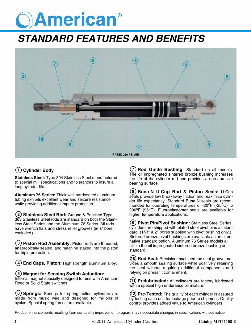
RATED 250 PSI AIR
Cylinder BodyStainless Steel: Type 304 Stainless Steel manufactured to special mill specifications and tolerances to insure a long cylinder life.
Aluminum 76 Series: Thick wall hardcoated aluminum tubing exhibits excellent wear and seizure resistance while providing additional impact protection.
Stainless Steel Rod: Ground & Polished Type 303 Stainless Steel rods are standard on both the Stain-less Steel Series and the Aluminum 76 Series. All rods have wrench flats and stress relief grooves (9/16" bore excluded).
Piston Rod Assembly: Piston rods are threaded, anaerobically sealed, and machine staked into the piston for triple protection.
End Caps, Piston: High strength aluminum alloy.
Magnet for Sensing Switch Actuation:Internal magnet specially designed for use with American Reed or Solid State switches.
Springs: Springs for spring action cylinders are made from music wire and designed for millions of cycles. Special spring forces are available.
Rod Guide Bushing: Standard on all models. The oil impregnated sintered bronze bushing increases the life of the cylinder rod and provides a non-abrasive bearing surface.
Buna-N U-Cup Rod & Piston Seals: U-Cup seals provide low breakaway friction and maximize cylin-der life expectancy. Standard Buna-N seals are recom-mended for operating temperatures of -20oF (-25oC) to 200oF (95oC). Fluoroelastomer seals are available for higher temperature applications.
Pivot Pin/Pivot Bushing: Stainless Steel Series cylinders are shipped with plated steel pivot pins as stan-dard. (13/4" & 2" bores supplied with pivot bushing only.) Sintered bronze pivot bushings are available as an alter-native standard option. Aluminum 76 Series models all utilize the oil impregnated sintered bronze bushing as standard.
Rod Seal: Precision machined rod seal groove pro-vides a smooth sealing surface while positively retaining the seal without requiring additional components and relying on press fit containment.
Prelubricated: All cylinders are factory lubricated with a special high endurance oil mixture.
Pre-Tested: The quality of each cylinder is assured by testing each unit for leakage prior to shipment. Quality control provides added value to American cylinders.
1
2
3
4
5
6
7
8
9
10
11
12

3 © 2011 American Cylinder Co., Inc. Catalog MFC 1108-E
HOW TO ORDER:
Example: 1 1/16" Bore Double Acting Universal Mount Magnetic Field Cylinder2" Stroke - Bumpers - Ports Rotated 90o
Model No.: 1062DVS-2.00-4-32-33
Model No.Composition: 1062 DVS - 2.00 - 4 - 32 - 33
Bore No. Option No.
Model MFC Piston
Stroke
Product enhancements resulting from our quality improvement program may necessitate changes in specifications without notice.
American Cylinder Distributors are located in every major industrial market.
Bore No. Model Description ModelMFC
Piston Standard Options No.9/16" 562 Stainless Single Acting Nose Mount SNS 4 1/8" Additional Rod Extension 1a
3/4" 750 Stainless Single Acting Universal Mount SVS Rear Pivot Bushing (Omit Pin) 2
11/16" 1062 Stainless Double Acting Nose Mount DNS Unmilled Threaded Rear Mtg. Stud 3b
11/8" 1125 Stainless Double Acting Universal Mount DVS Quad-XWiper/Seal 5
11/4" 1250 Aluminum Double Acting Nose Mount DN Magnalube 6
11/2" 1500 Aluminum Double Acting Universal Mount DV Fluoroelastomer Seals 31
13/4" 1750 Stainless Double Acting Block Front DBFS Bumpers 32c
2" 2000 Stainless Double Acting Block Front Trunnion DBFTS Ports Rotated 90o 33
21/2" 2500 Stainless Double Acting Block Rear DBRS
Stainless Double Acting Block Rear Trunnion DBRTS
Stainless Double End Rod DES
Aluminum Double End Rod DENOTES
a 11/16" bore only.b Reduces tang length by .250 on the 11/2" bore models. Same thread as nose thread.c See page 4 for Bumper Length Adder.
4 © 2011 American Cylinder Co., Inc. Catalog MFC 1108-E
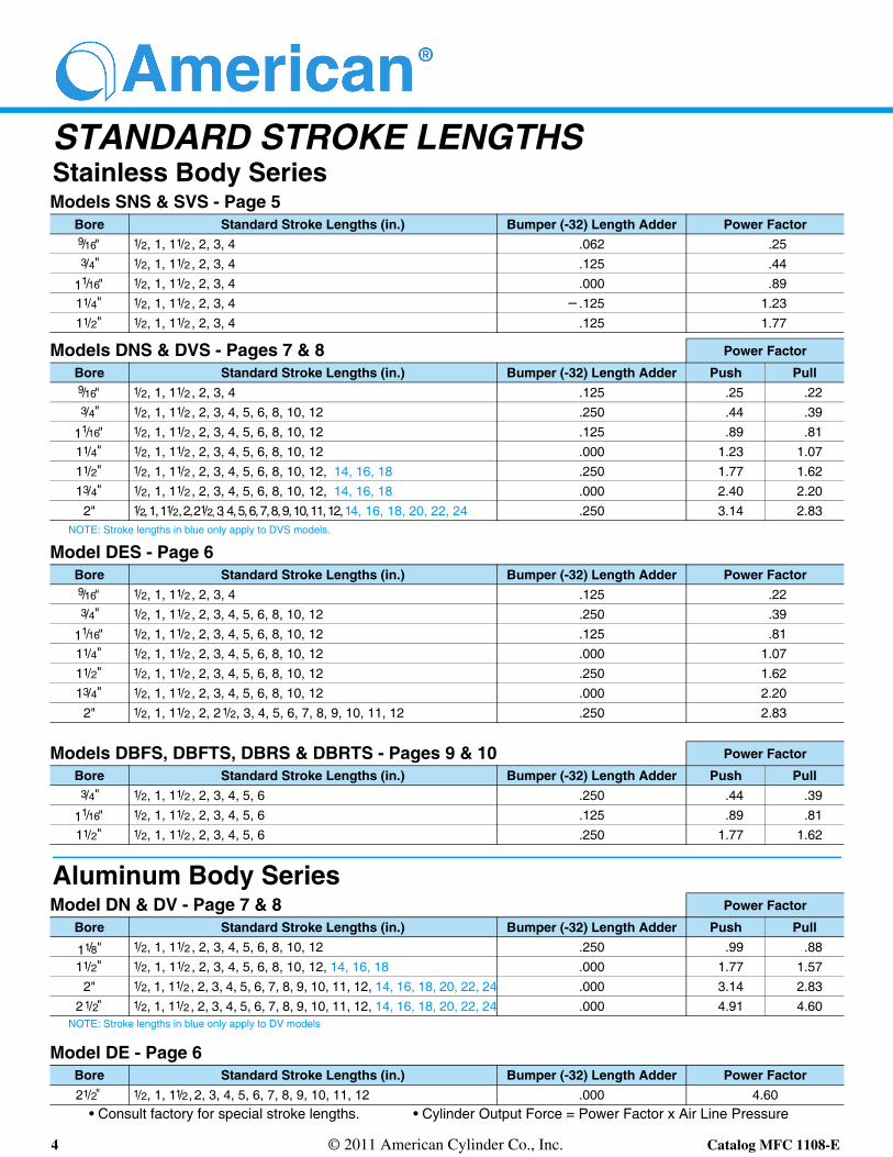
STANDARD STROKE LENGTHSStainless Body Series
NOTE: Stroke lengths in blue only apply to DVS models.
Aluminum Body Series
NOTE: Stroke lengths in blue only apply to DV models
• Consult factory for special stroke lengths. • Cylinder Output Force = Power Factor x Air Line Pressure
Models SNS & SVS - Page 5Bore Standard Stroke Lengths (in.) Bumper (-32) Length Adder Power Factor9/16" 1/2, 1, 11/2 , 2, 3, 4 .062 .253/4" 1/2, 1, 11/2 , 2, 3, 4 .125 .44
11/16" 1/2, 1, 11/2 , 2, 3, 4 .000 .8911/4" 1/2, 1, 11/2 , 2, 3, 4 .125 1.2311/2" 1/2, 1, 11/2 , 2, 3, 4 .125 1.77
Models DNS & DVS - Pages 7 & 8 Power Factor
Bore Standard Stroke Lengths (in.) Bumper (-32) Length Adder Push Pull9/16" 1/2, 1, 11/2 , 2, 3, 4 .125 .25 .223/4" 1/2, 1, 11/2 , 2, 3, 4, 5, 6, 8, 10, 12 .250 .44 .39
11/16" 1/2, 1, 11/2 , 2, 3, 4, 5, 6, 8, 10, 12 .125 .89 .8111/4" 1/2, 1, 11/2 , 2, 3, 4, 5, 6, 8, 10, 12 .000 1.23 1.0711/2" 1/2, 1, 11/2 , 2, 3, 4, 5, 6, 8, 10, 12, 14, 16, 18 .250 1.77 1.6213/4" 1/2, 1, 11/2 , 2, 3, 4, 5, 6, 8, 10, 12, 14, 16, 18 .000 2.40 2.20
2" 1/2, 1, 11/2, 2, 21/2, 3, 4, 5, 6, 7, 8, 9, 10, 11, 12, 14, 16, 18, 20, 22, 24 .250 3.14 2.83
Model DES - Page 6Bore Standard Stroke Lengths (in.) Bumper (-32) Length Adder Power Factor9/16" 1/2, 1, 11/2 , 2, 3, 4 .125 .223/4" 1/2, 1, 11/2 , 2, 3, 4, 5, 6, 8, 10, 12 .250 .39
11/16" 1/2, 1, 11/2 , 2, 3, 4, 5, 6, 8, 10, 12 .125 .8111/4" 1/2, 1, 11/2 , 2, 3, 4, 5, 6, 8, 10, 12 .000 1.0711/2" 1/2, 1, 11/2 , 2, 3, 4, 5, 6, 8, 10, 12 .250 1.6213/4" 1/2, 1, 11/2 , 2, 3, 4, 5, 6, 8, 10, 12 .000 2.20
2" 1/2, 1, 11/2 , 2, 21/2, 3, 4, 5, 6, 7, 8, 9, 10, 11, 12 .250 2.83
Models DBFS, DBFTS, DBRS & DBRTS - Pages 9 & 10 Power Factor
Bore Standard Stroke Lengths (in.) Bumper (-32) Length Adder Push Pull3/4" 1/2, 1, 11/2 , 2, 3, 4, 5, 6 .250 .44 .39
11/16" 1/2, 1, 11/2 , 2, 3, 4, 5, 6 .125 .89 .8111/2" 1/2, 1, 11/2 , 2, 3, 4, 5, 6 .250 1.77 1.62
Model DN & DV - Page 7 & 8 Power Factor
Bore Standard Stroke Lengths (in.) Bumper (-32) Length Adder Push Pull
11/8" 1/2, 1, 11/2 , 2, 3, 4, 5, 6, 8, 10, 12 .250 .99 .8811/2" 1/2, 1, 11/2 , 2, 3, 4, 5, 6, 8, 10, 12, 14, 16, 18 .000 1.77 1.57
2" 1/2, 1, 11/2 , 2, 3, 4, 5, 6, 7, 8, 9, 10, 11, 12, 14, 16, 18, 20, 22, 24 .000 3.14 2.8321/2" 1/2, 1, 11/2 , 2, 3, 4, 5, 6, 7, 8, 9, 10, 11, 12, 14, 16, 18, 20, 22, 24 .000 4.91 4.60
Model DE - Page 6Bore Standard Stroke Lengths (in.) Bumper (-32) Length Adder Power Factor21/2" 1/2, 1, 11/2, 2, 3, 4, 5, 6, 7, 8, 9, 10, 11, 12 .000 4.60
5 © 2011 American Cylinder Co., Inc. Catalog MFC 1108-E
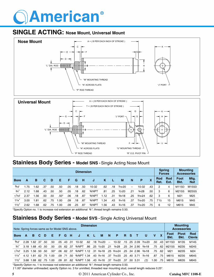
SINGLE ACTING: Nose Mount, Universal Mount
Stainless Body Series - Model SNS - Single Acting Nose Mount
Dimension SpringForces
Mounting Accessories
Bore A B C D E F G H J K L M N P X Rod Ret.
Rod Ext.
Foot Bkt.
Mtg.Nut
9/16" 1.75 1.62 .37 .50 .50 .05 .18 .50 10-32 .62 .18 7/16-20 -- 10-32 .43 2 4 M11SD M15SD
3/4" 2.12 1.68 .43 .50 .50 .05 .18 .62 1/8 NPT .81 .25 1/2-20 .21 1/4-28 .50 3 6 M21SS M25SS
11/16" 2.37 1.56 .50 .50 .50* .06 .18 .87 1/8 NPT 1.12 .31 5/8-18 .25 5/16-24 .62 3 6 M21 M25
11/4" 3.00 1.81 .62 .75 1.00 .09 .18 .87 1/8 NPT 1.34 .43 3/4-16 .37 7/16-20 .75 71/2 15 M61S M45
11/2" 2.62 1.68 .62 .75 1.00 .09 .25 .87 1/8 NPT 1.56 .43 3/4-16 .37 7/16-20 .75 6 12 M61S M45
*Specify Option no. 1 to increase rod extension an additional 1/8 "; thread length remains 0.50.
Stainless Body Series - Model SVS - Single Acting Universal Mount
DimensionNote: Spring forces same as for Model SNS above.
Mounting Accessories
Bore A B C D E F G H J K L M N P R S T U V X Foot Bkt.
PivotBkt.
RodClevis
9/16" 2.28 1.62 .37 .50 .50 .05 .43 .31 10-32 .62 .18 7/16-20 -- 10-32 .15 .25 2.09 7/16-20 .50 .43 M11SD M13S M14S
3/4" 3.18 1.68 .43 .50 .50 .05 .62 .37 1/8NPT .86 .25 1/2-20 .21 1/4-28 .25 .34 2.90 5/8-18 .75 .62 M21SS M23S M24S
11/16" 3.25 1.56 .50 .50 .50* .06 .62 .37 1/8NPT 1.12 .31 5/8-18 .25 5/16-24 .25 .34 2.96 5/8-18 .75 .62 M21 M23S M24
11/4" 4.12 1.81 .62 .75 1.00 .09 .71 .50 1/8NPT 1.34 .43 3/4-16 .37 7/16-20 .25 .40 3.71 3/4-16 .87 .75 M61S M23S M64S
11/2" 3.68 1.68 .62 .75 1.00 .09 .81 .62 1/8NPT 1.56 .43 3/4-16 .37 7/16-20 .37 .50 3.31 (†) 1.00 .75 M61S M63S M64S
*Specify Option no. 1 to increase rod extension an additional 1/8 "; thread length remains 0.50. † 1.00" diameter unthreaded; specify Option no. 3 for unmilled, threaded rear mounting stud, overall length reduces 0.25".
Nose Mount
Universal Mount
F
X
C
F
“L” DIA. ROD
“U” MOUNTING THREAD
“R” O.D. PIVOT PIN
“J” PORT
A + ( B PER EACH INCH OF STROKE )
K
G
“J” PORT“N” ACROSS FLATS
“P” ROD THREAD
E
D
X H
“M” MOUNTING THREAD
“L” DIA. ROD
“N” ACROSS FLATS
“P” ROD THREAD
“M” MOUNTING THREAD
D
E
C
F
G
S
K
H
V
A + ( B PER EACH INCH OF STROKE )
T + ( B PER EACH INCH OF STROKE )

6 © 2011 American Cylinder Co., Inc. Catalog MFC 1108-E
DOUBLE ACTING: Double End Rod
Stainless Body Series - Model DES - Double End Rod
Dimension Mounting Accessories
Bore A C D E F G H J K L M N P X Foot Bkt.
RodClevis
Mtg.Nut
9/16" 3.93 .37 .50 .50 .05 .37 2.18 10-32 .62 .18 7/16-20 -- 10-32 .43 M11SD M14S M15SD3/4" 5.00 .50 .50 .50 .06 .46 3.00 1/8NPT .86 .25 5/8-18 .21 1/4-28 .62 M21 M24S M25
11/16" 5.37 .50 .50 .62 .09 .56 3.12 1/8NPT 1.12 .31 5/8-18 .25 5/16-24 .62 M21 M24 M2511/4" 7.06 .62 .75 1.00 .09 .56 3.81 1/8NPT 1.34 .43 3/4-16 .37 7/16-20 .75 M61S M64S M4511/2" 6.62 .62 .75 1.00 .09 .62 3.37 1/8NPT 1.56 .43 3/4-16 .37 7/16-20 .75 M61S M64S M4513/4" 8.31 .75 .87 1.18 .09 .87 4.43 1/4NPT 1.84 .50 1-14 .43 1/2-20 1.03 M71S M94 M65
2" 8.31 .81 .87 1.25 .10 .68 4.18 1/4NPT 2.09 .62 11/4-12 .56 1/2-20 1.37 M81S M94 M85
Aluminum 76 Body Series - Model DE - Double End Rod
Dimension Mounting Accessories
Bore A C D E F G H J K L M N P X Foot Bkt.
RodClevis
Mtg.Nut
2 1/2" 8.31 .81 .87 1.25 .12 .68 4.18 1/4NPT 2.73 .62 13/8-12 .56 1/2-20 1.50 M91 M94 M95
Double End Rod
C
E
D
“L” DIA. ROD
“M” MOUNTING THREAD - BOTH ENDS
F
A + ( 2 TIMES STROKE )
“N” ACROSS FLATS - BOTH ENDS
“P” ROD THREAD - BOTH ENDS
G K
E + STROKE
H + STROKE
X
D
F“J” PORTS
X
C
G
D
7 © 2011 American Cylinder Co., Inc. Catalog MFC 1108-E
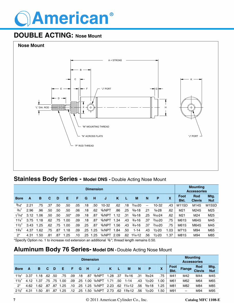
DOUBLE ACTING: Nose Mount
Stainless Body Series - Model DNS - Double Acting Nose Mount
Dimension MountingAccessories
Bore A B C D E F G H J K L M N P X FootBkt.
RodClevis
Mtg.Nut
9/16" 2.21 .75 .37 .50 .50 .05 .18 .50 10-32 .62 .18 7/16-20 -- 10-32 .43 M11SD M14S M15SD3/4" 2.96 .96 .50 .50 .50 .06 .18 .62 1/8NPT .86 .25 5/8-18 .21 1/4-28 .62 M21 M24S M25
11/16" 3.12 1.06 .50 .50 .50* .09 .18 .87 1/8NPT 1.12 .31 5/8-18 .25 5/16-24 .62 M21 M24 M2511/4" 3.75 1.18 .62 .75 1.00 .09 .18 .87 1/8NPT 1.34 .43 3/4-16 .37 7/16-20 .75 M61S M64S M4511/2" 3.43 1.25 .62 .75 1.00 .09 .25 .87 1/8NPT 1.56 .43 3/4-16 .37 7/16-20 .75 M61S M64S M4513/4" 4.37 1.62 .75 .87 1.18 .09 .25 1.25 1/4NPT 1.84 .50 1-14 .43 1/2-20 1.03 M71S M94 M652" 4.31 1.50 .81 .87 1.25 .10 .25 1.25 1/4NPT 2.09 .62 11/4-12 .56 1/2-20 1.37 M81S M94 M85
*Specify Option no. 1 to increase rod extension an additional 1/8 "; thread length remains 0.50.
Aluminum Body 76 Series- Model DN - Double Acting Nose Mount
Dimension MountingAccessories
Bore A B C D E F G H J K L M N P X FootBkt. Flange Rod
ClevisMtg.Nut
11/8" 3.37 1.18 .62 .50 .75 .09 .18 .87 1/8NPT 1.28 .37 3/4-16 .31 3/8-24 .75 M41 M42 M44 M4511/2" 4.12 1.37 .75 .75 1.00 .09 .25 1.00 1/4NPT 1.71 .50 1-14 .43 1/2-20 1.00 M61 M62 M64 M65
2" 4.62 1.62 .87 .87 1.25 .10 .25 1.25 1/4NPT 2.23 .62 11/4-12 .56 5/8-18 1.25 M81 M82 M84 M8521/2" 4.31 1.50 .81 .87 1.25 .12 .25 1.50 1/4NPT 2.73 .62 13/8-12 .56 1/2-20 1.50 M91 -- M94 M95
Nose Mount
C
E
D
“L” DIA. ROD
“M” MOUNTING THREAD
F
A + STROKE
“N” ACROSS FLATS
“P” ROD THREAD
G
K
HX
B
“J” PORT
“J” PORT

8 © 2011 American Cylinder Co., Inc. Catalog MFC 1108-E
DOUBLE ACTING: Universal Mount
Stainless Body Series - Model DVS - Double Acting Universal Mount
Dimension MountingAccessories
Bore A B C D E F G H J K L M N P R S T U V W X FootBkt.
PivotBkt.
RodClevis
9/16" 2.75 .75 .37 .50 .50 .05 .43 .31 10-32 .62 .18 7/16-20 -- 10-32 .15 .25 2.56 7/16-20 .50 -- .43 M11SD M13S M14S
3/4" 4.03 .96 .50 .50 .50 .06 .62 .37 1/8 NPT .86 .25 5/8-18 .21 1/4-28 .25 .34 3.75 5/8-18 .75 -- .62 M21 M23S M24S
11/16" 4.00 1.06 .50 .50 .50* .09 .62 .37 1/8 NPT 1.12 .31 5/8-18 .25 5/16-24 .25 .34 3.71 5/8-18 .75 -- .62 M21 M23S M24
11/4" 4.87 1.18 .62 .75 1.00 .09 .71 .50 1/8 NPT 1.34 .43 3/4-16 .37 7/16-20 .25 .40 4.46 3/4-16 .87 -- .75 M61S M23S M64S
11/2" 4.50 1.25 .62 .75 1.00 .09 .81 .62 1/8 NPT 1.56 .43 3/4-16 .37 7/16-20 .37 .50 4.12 (†) 1.00 -- .75 M61S M63S M64S
13/4" 5.93 1.62 .75 .87 1.18 .09 1.12 .62 1/4 NPT 1.84 .50 1-14 .43 1/2-20 -- .50 5.43 1-14 --- .37 1.03 M71S M73SP M94
2" 5.68 1.50 .81 .87 1.25 .10 .93 .75 1/4 NPT 2.09 .62 11/4-12 .56 1/2-20 -- .56 5.25 11/4-12 -- .37 1.37 M81S M93 M94
*Specify Option no. 1 to increase rod extension an additional 1/8"; thread length remains 0.50. † 1.00" diameter unthreaded; specify Option no. 3 for unmilled, threaded rear mounting stud, overall length reduces 0.25".
Aluminum Body 76 Series - Model DV - Double Acting Universal Mount
Dimension MountingAccessories
Bore A B C D E F G H J K L M N P S T U W X FootBkt. Flange Pivot
Bkt.Rod
ClevisMtg.Nut
11/8" 4.50 1.18 .62 .50 .75 .09 .81 .50 1/8 NPT 1.28 .37 3/4-16 .31 3/8-24 .50 4.18 3/4-16 .25 .75 M41 M42 M43 M44 M45
11/2" 5.62 1.37 .75 .75 1.00 .09 1.09 .75 1/4 NPT 1.71 .50 1-14 .43 1/2-20 .71 5.21 1-14 .31 1.00 M61 M62 M63 M64 M65
2" 6.12 1.62 .87 .87 1.25 .10 1.09 .75 1/4 NPT 2.23 .62 11/4-12 .56 5/8-18 .71 5.71 11/4-12 .31 1.25 M81 M82 M83 M84 M85
2 1/2" 5.68 1.50 .81 .87 1.25 .12 .93 .75 1/4 NPT 2.73 .62 13/8-12 .56 1/2-20 .56 5.25 13/8-12 .37 1.50 M91 -- M93 M94 M95
Universal Mount
C
E
D
“L” DIA. ROD
“M” MOUNTING THREAD
F
A + STROKE
“N” ACROSS FLATS
“P” ROD THREAD
G
K
V
T + STROKE
X
H
S
“J” PORTS
“W” I.D. PIVOT BUSHING
“R” O.D. PIVOT PINor
“U” MOUNTING THREAD
B
F
9 © 2011 American Cylinder Co., Inc. Catalog MFC 1108-E
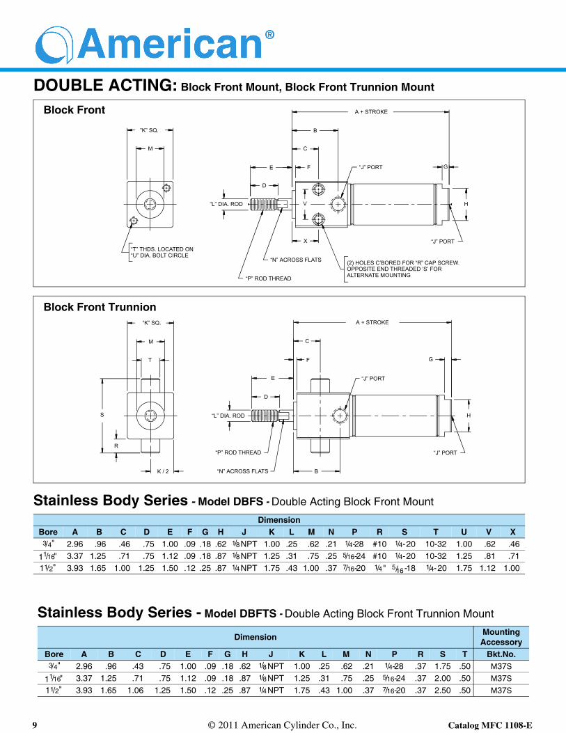
DOUBLE ACTING: Block Front Mount, Block Front Trunnion Mount
Stainless Body Series - Model DBFS - Double Acting Block Front Mount
DimensionBore A B C D E F G H J K L M N P R S T U V X
3/4" 2.96 .96 .46 .75 1.00 .09 .18 .62 1/8NPT 1.00 .25 .62 .21 1/4-28 #10 1/4-20 10-32 1.00 .62 .46
11/16" 3.37 1.25 .71 .75 1.12 .09 .18 .87 1/8NPT 1.25 .31 .75 .25 5/16-24 #10 1/4-20 10-32 1.25 .81 .7111/2" 3.93 1.65 1.00 1.25 1.50 .12 .25 .87 1/4NPT 1.75 .43 1.00 .37 7/16-20 1/4" 5/16-18 1/4-20 1.75 1.12 1.00
Stainless Body Series - Model DBFTS - Double Acting Block Front Trunnion Mount
Dimension MountingAccessory
Bore A B C D E F G H J K L M N P R S T Bkt.No.3/4" 2.96 .96 .43 .75 1.00 .09 .18 .62 1/8NPT 1.00 .25 .62 .21 1/4-28 .37 1.75 .50 M37S
11/16" 3.37 1.25 .71 .75 1.12 .09 .18 .87 1/8NPT 1.25 .31 .75 .25 5/16-24 .37 2.00 .50 M37S
11/2" 3.93 1.65 1.06 1.25 1.50 .12 .25 .87 1/4NPT 1.75 .43 1.00 .37 7/16-20 .37 2.50 .50 M37S
Block Front Trunnion
Block Front
B
E
D
“L” DIA. ROD
“T” THDS. LOCATED ON
F
A + STROKE
“N” ACROSS FLATS
“P” ROD THREAD
G
H
T
A + STROKE
R
K / 2
S
“J” PORT
B
(2) HOLES C’BORED FOR “R” CAP SCREW.
“J” PORT
M
“K” SQ.
C
M
”K” SQ.
“U” DIA. BOLT CIRCLE
“L” DIA. ROD
E
D
F
C
G“J” PORT
“J” PORT
H
“N” ACROSS FLATS
“P” ROD THREAD
OPPOSITE END THREADED ‘S’ FORALTERNATE MOUNTING
X
V

10 © 2011 American Cylinder Co., Inc. Catalog MFC 1108-E
DOUBLE ACTING: Block Rear Mount, Block Rear Trunnion Mount
Stainless Body Series - Model DBRS - Double Acting Block Rear Mount
DimensionBore A B C D E F G H J K L M N P R S
3/4" 3.53 .96 .50 .75 1.00 .06 .75 .43 1/8NPT 1.00 .25 5/8-18 .21 1/4-28 10-32 1.00
11/16" 3.62 1.06 .50 .75 1.12 .09 .75 .43 1/8NPT 1.25 .31 5/8-18 .25 5/16-24 10-32 1.2511/2" 4.12 1.21 .62 1.25 1.50 .09 1.00 .62 1/4NPT 1.75 .43 3/4-16 .37 7/16-20 1/4-20 1.75
Stainless Body Series - Model DBRTS - Double Acting Block Rear Trunnion Mount
Dimension MountingAccessory
Bore A B C D E F G H J K L M N P R S T V Bkt.No.3/4" 3.53 .96 .50 .75 1.00 .06 .75 .43 1/8NPT 1.00 .25 5/8-18 .21 1/4-28 .37 1.75 .50 .37 M37S
11/16" 3.62 1.06 .50 .75 1.12 .09 .75 .43 1/8NPT 1.25 .31 5/8-18 .25 5/16-24 .37 2.00 .50 .37 M37S
11/2" 4.12 1.21 .62 1.25 1.50 .09 1.00 .62 1/4NPT 1.75 .43 3/4-16 .37 7/16-20 .37 2.50 .50 .50 M37S
Block Rear Trunnion
Block Rear
C
E
D
“L” DIA. ROD
“M” MOUNTING THREAD
F
A + STROKE
“N” ACROSS FLATS
“P” ROD THREAD
G “K” SQ.
K / 2
A + STROKE
V
S
H
“J” PORTS
R
TWO “R” MTG THREADS LOCATED
“M” MOUNTING THREAD
“N” ACROSS FLATS
“P” ROD THREAD
T
B
ON “S” DIA. BOLT CIRCLE
F “J” PORTS
H
G
C
E
D
B
“L” DIA. ROD
“K” SQ.
11 © 2011 American Cylinder Co., Inc. Catalog MFC 1108-E
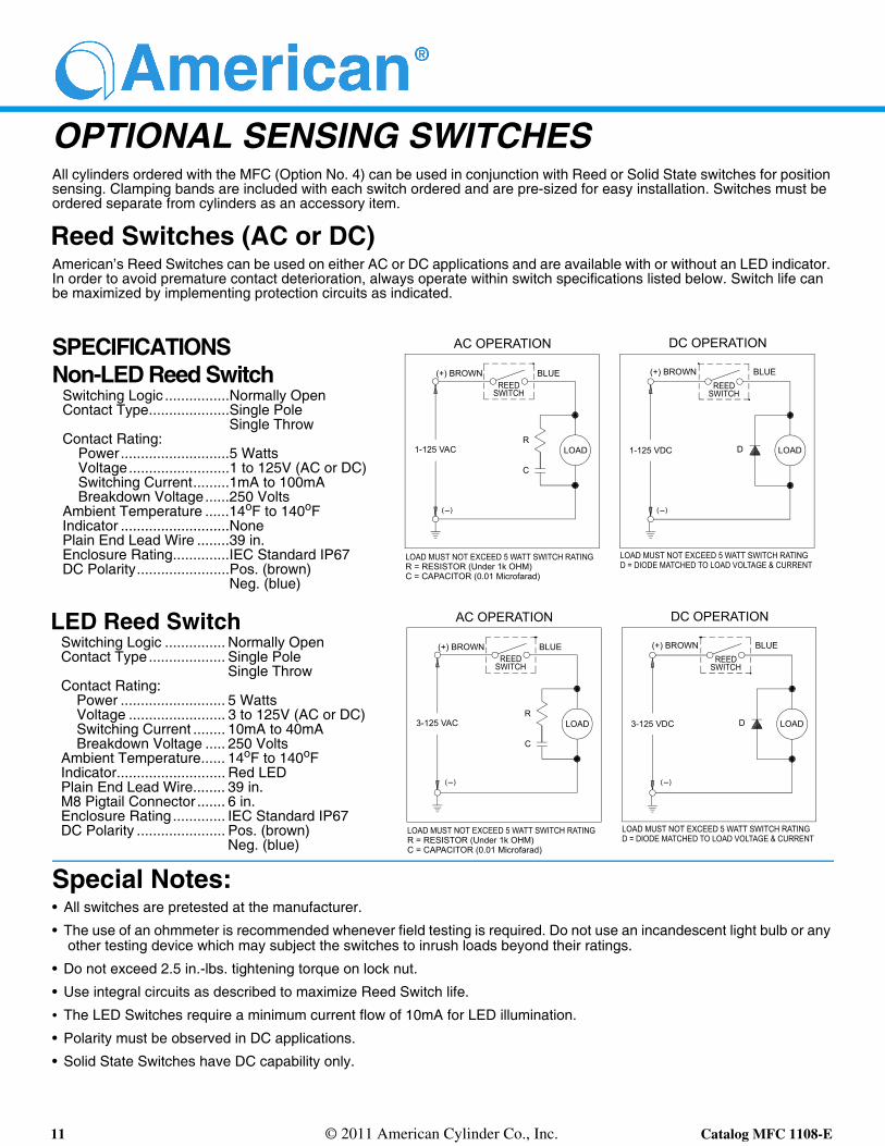
OPTIONAL SENSING SWITCHESAll cylinders ordered with the MFC (Option No. 4) can be used in conjunction with Reed or Solid State switches for position sensing. Clamping bands are included with each switch ordered and are pre-sized for easy installation. Switches must be ordered separate from cylinders as an accessory item.
Reed Switches (AC or DC)American’s Reed Switches can be used on either AC or DC applications and are available with or without an LED indicator. In order to avoid premature contact deterioration, always operate within switch specifications listed below. Switch life can be maximized by implementing protection circuits as indicated.
Special Notes:• All switches are pretested at the manufacturer.
• The use of an ohmmeter is recommended whenever field testing is required. Do not use an incandescent light bulb or any other testing device which may subject the switches to inrush loads beyond their ratings.
• Do not exceed 2.5 in.-lbs. tightening torque on lock nut.
• Use integral circuits as described to maximize Reed Switch life.
• The LED Switches require a minimum current flow of 10mA for LED illumination.
• Polarity must be observed in DC applications.
• Solid State Switches have DC capability only.
SPECIFICATIONSNon-LED Reed Switch
Switching Logic ................Normally OpenContact Type....................Single Pole
Single ThrowContact Rating:
Power...........................5 WattsVoltage.........................1 to 125V (AC or DC)Switching Current.........1mA to 100mABreakdown Voltage......250 Volts
Ambient Temperature ......14oF to 140oFIndicator ...........................NonePlain End Lead Wire ........39 in. Enclosure Rating..............IEC Standard IP67DC Polarity.......................Pos. (brown)
Neg. (blue)
LED Reed SwitchSwitching Logic ............... Normally OpenContact Type................... Single Pole
Single ThrowContact Rating:
Power .......................... 5 WattsVoltage ........................ 3 to 125V (AC or DC)Switching Current ........ 10mA to 40mABreakdown Voltage ..... 250 Volts
Ambient Temperature...... 14oF to 140oFIndicator........................... Red LEDPlain End Lead Wire........ 39 in. M8 Pigtail Connector ....... 6 in.Enclosure Rating ............. IEC Standard IP67DC Polarity ...................... Pos. (brown)
Neg. (blue)
(+) BROWN
AC OPERATION
BLUEREED
SWITCH
LOADR
C
3-125 VAC
LOAD MUST NOT EXCEED 5 WATT SWITCH RATINGR = RESISTOR (Under 1k OHM)C = CAPACITOR (0.01 Microfarad)
DC OPERATION
(+) BROWN BLUE
LOAD MUST NOT EXCEED 5 WATT SWITCH RATINGD = DIODE MATCHED TO LOAD VOLTAGE & CURRENT
LOADD3-125 VDC
REEDSWITCH
(+) BROWN
AC OPERATION
BLUEREED
SWITCH
LOADR
C
1-125 VAC
LOAD MUST NOT EXCEED 5 WATT SWITCH RATINGR = RESISTOR (Under 1k OHM)C = CAPACITOR (0.01 Microfarad)
DC OPERATION
(+) BROWN BLUE
LOAD MUST NOT EXCEED 5 WATT SWITCH RATINGD = DIODE MATCHED TO LOAD VOLTAGE & CURRENT
LOADD1-125 VDC
REEDSWITCH
( )( )
( ) ( )

12 © 2011 American Cylinder Co., Inc. Catalog MFC 1108-E
OPTIONAL SENSING SWITCHES (Continued)Solid State Switches (DC only)American’s Solid State Switches are designed for DC applications only. With no mechanical parts to wear out or arc, the solid state circuitry provides a compact, reliable positioning switch for extended service life when used within the specified parameters.
SWITCH DIMENSIONAL DATAStd. Lead Wires w/Bands Pigtail Connection Type w/Bands
SPECIFICATIONSSolid State Switch
Sinking (NPN) Sourcing (PNP)Switching Logic .............................. Normally Open Switching Logic .............................. Normally OpenSwitching Voltage ...................... 5 VDC to 30 VDC Switching Voltage.......................5 VDC to 30 VDCSwitching Current.............. 100mA Max. @ 5 VDC Switching Current ..............100mA Max. @ 12 VDC.......................................... 200mA Max. @ 12 VDC ..........................................200mA Max. @ 24 VDC.......................................... 200mA Max. @ 24 VDCCurrent Consumption.......... 10mA Max. @ 12 VDC Current Consumption ............7mA Max. @ 12 VDC............................................ 20mA Max. @ 24 VDC ............................................14mA Max. @ 24 VDCAmbient Temperature ......................14oF to 140oF Ambient Temperature...................... 14oF to 140oFIndicator ...................................................Red LED Indicator................................................ Green LEDPlain End Lead Wire ..................................... 39 in. Plain End Lead Wire...................................... 39 in.M8 Pigtail Connector........................................6 in. M8 Pigtail Connector ....................................... 6 in.Enclosure Rating...................... IEC Standard IP66 Enclosure Rating...................... IEC Standard IP66
5 - 30 VDC 5 - 30 VDC
( + ) ( + )
SOURCING CIRCUITSINKING CIRCUIT
BLACK
LOAD
BLACK
LOAD
SOLID STATESWITCH
(PNP)
SOLID STATESWITCH
(NPN)
BLU
EB
RO
WN
BLU
EB
RO
WN
Wiring Diagram:Wiring Diagram:
( ) ( )
SENSING SWITCH
CLAMPING BAND
.61
.89.43
1.03
.06 .06
.59
13 © 2011 American Cylinder Co., Inc. Catalog MFC 1108-E
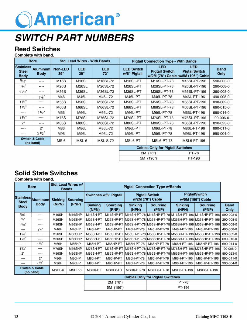
SWITCH PART NUMBERSReed SwitchesComplete with band.
Solid State SwitchesComplete with band.
Bore Std. Lead Wires - With Bands Pigtail Connection Type - With BandsStainless
Steel Body
Aluminum Body
Non-LED39"
LED39"
LED72"
LED Switch w/6" Pigtail
LED Pigtail Switch
w/2M (78") Cable
LED PigtailSwitch
w/5M (196") Cable
BandOnly
9/16" ---- M16S M16SL M16SL-72 M16SL-PT M16SL-PT-78 M16SL-PT-196 590-003-03/4" ---- M26S M26SL M26SL-72 M26SL-PT M26SL-PT-78 M26SL-PT-196 290-008-0
11/16" ---- M36S M36SL M36SL-72 M36SL-PT M36SL-PT-78 M36SL-PT-196 390-008-0---- 11/8" M46 M46L M46L-72 M46L-PT M46L-PT-78 M46L-PT-196 490-008-0
11/4" ---- M56S M56SL M56SL-72 M56SL-PT M56SL-PT-78 M56SL-PT-196 090-002-011/2" ---- M66S M66SL M66SL-72 M66SL-PT M66SL-PT-78 M66SL-PT-196 690-015-0---- 11/2" M66 M66L M66L-72 M66L-PT M66L-PT-78 M66L-PT-196 690-014-0
13/4" ---- M76S M76SL M76SL-72 M76SL-PT M76SL-PT-78 M76SL-PT-196 I90-006-02" ---- M86S M86SL M86SL-72 M86SL-PT M86SL-PT-78 M86SL-PT-196 890-023-0---- 2" M86 M86L M86L-72 M86L-PT M86L-PT-78 M86L-PT-196 890-011-0---- 2 1/2" M96 M96L M96L-72 M96L-PT M96L-PT-78 M96L-PT-196 990-004-0Switch & Cable
(no band) MS-6 MSL-6 MSL-S-72 MSL6-PT MSL6-PT-78 MSL6-PT-196
Cables Only for Pigtail Switches2M (78") PT-78
5M (196") PT-196
Bore Std. Lead Wires w/Bands Pigtail Connection Type w/Bands
Stainless Steel Body
Aluminum Body
Sinking (NPN)
Sourcing (PNP)
Switches w/6" Pigtail Pigtail Switchw/2M (78") Cable
PigtailSwitchw/5M (196") Cable
Sinking (NPN)
Sourcing (PNP)
Sinking (NPN)
Sourcing (PNP)
Sinking (NPN)
Sourcing (PNP)
Band Only
9/16" ---- M16SH M16SHP M16SH-PT M16SHP-PT M16SH-PT-78 M16SHP-PT-78 M16SH-PT-196 M16SHP-PT-196 590-003-03/4" ---- M26SH M26SHP M26SH-PT M26SHP-PT M26SH-PT-78 M26SHP-PT-78 M26SH-PT-196 M26SHP-PT-196 290-008-0
11/16" ---- M36SH M36SHP M36SH-PT M36SHP-PT M36SH-PT-78 M36SHP-PT-78 M36SH-PT-196 M36SHP-PT-196 390-008-0---- 11/8" M46H M46HP M46H-PT M46HP-PT M46H-PT-78 M46HP-PT-78 M46H-PT-196 M46HP-PT-196 490-008-0
11/4" ---- M56SH M56SHP M56SH-PT M56SHP-PT M56SH-PT-78 M56SHP-PT-78 M56SH-PT-196 M56SHP-PT-196 090-002-011/2" ---- M66SH M66SHP M66SH-PT M66SHP-PT M66SH-PT-78 M66SHP-PT-78 M66SH-PT-196 M66SHP-PT-196 690-015-0---- 11/2" M66H M66HP M66H-PT M66HP-PT M66H-PT-78 M66HP-PT-78 M66H-PT-196 M66HP-PT-196 690-014-0
13/4" ---- M76SH M76SHP M76SH-PT M76SHP-PT M76SH-PT-78 M76SHP-PT-78 M76SH-PT-196 M76SHP-PT-196 I90-006-02" ---- M86SH M86SHP M86SH-PT M86SHP-PT M86SH-PT-78 M86SHP-PT-78 M86SH-PT-196 M86SHP-PT-196 890-023-0---- 2" M86H M86HP M86H-PT M86HP-PT M86H-PT-78 M86HP-PT-78 M86H-PT-196 M86HP-PT-196 890-011-0---- 2 1/2" M96H M96HP M96H-PT M96HP-PT M96H-PT-78 M96HP-PT-78 M96H-PT-196 M96HP-PT-196 990-004-0Switch & Cable
(no band) MSHL-6 MSHP-6 MSH6-PT MSHP6-PT MSH6-PT-78 MSHP6-PT-78 MSH6-PT-196 MSH6-PT-196
Cables Only for Pigtail Switches2M (78") PT-78
5M (196") PT-196

14 © 2011 American Cylinder Co., Inc. Catalog MFC 1108-E
MOUNTING ACCESSORIES: Dimensional Data
Foot BracketStainless Body Series
Aluminum Body Series
Mounting Nut
Flange Mount Aluminum Body Series
Bore Foot Bkt. No.
DimensionA B C D E F G H J K L
9/16" M11SD 1.00 1.37 .07 .18 .56 .43 .62 .93 .68 .31 .183/4" S.A. M21SS 1.25 1.62 .10 .18 .68 .50 .75 1.09 .81 .43 .18
3/4" M21 1.50 1.87 .12 .28 .81 .62 1.00 1.37 .93 .56 .18
11/16" M21 1.50 1.87 .12 .28 .81 .62 1.00 1.37 .93 .56 .1811/4" M61S 1.87 2.50 .15 .28 1.00 .75 1.50 1.75 1.25 .75 .3111/2" M61S 1.87 2.50 .15 .28 1.00 .75 1.50 1.75 1.25 .75 .3113/4" M71S 2.25 3.00 .18 .34 1.25 1.03 1.50 2.12 1.50 .87 .37
2" M81S 2.25 3.12 .25 .34 1.50 1.37 1.62 2.56 1.56 1.00 .43Note: One mounting nut is provided with each foot bracket ordered.
Bore Foot Bkt. No.
DimensionA B C D E F G H J K L
11/8" M41 1.50 1.87 .12 .28 .87 .75 1.06 1.50 .93 .59 .1811/2" M61 1.87 2.37 .21 .28 1.18 1.00 1.37 2.06 1.18 .78 .25
2" M81 2.37 3.00 .25 .34 1.50 1.25 1.68 2.56 1.50 .96 .312 1/2" M91 2.87 3.75 .25 .34 1.75 1.50 1.62 3.06 1.87 1.00 .43Note: One mounting nut is provided with each foot bracket ordered.
BoreMtg. Nut No. Dimension
SS Body AL Body A B C9/16" M15SD -- 7/16-20 .68 .25
3/4" S.A. M25SS -- 1/2-20 .75 .313/4" M25 -- 5/8-18 .93 .37
11/16" M25 -- 5/8-18 .93 .37
11/8" -- M45 3/4-16 1.12 .4211/4" M45 -- 3/4-16 1.12 .4211/2" M45 -- 3/4-16 1.12 .4211/2" -- M65 1-14 1.50 .5413/4" M65 -- 1-14 1.50 .54
2" M85 -- 11/4-12 1.87 .542" -- M85 11/4-12 1.87 .54
2 1/2" -- M95 13/8-12 1.87 .50
Bore Flange No.Dimension
A B C D E F G H
11/8" M42 2.00 2.50 .25 .75 .62 .28 .25 1.0011/2" M62 2.50 3.25 .31 1.00 .75 .28 .37 1.25
2" M82 2.87 3.62 .31 1.25 .87 .28 .37 1.43Note: One mounting nut is provided with each flange ordered.
A
C
D - DIA.
F - DIA.
C
G
H
F - DIA. (TYP.)
B
B
A - UNF THREAD
C
J
BL
E
A
KD - TYP.
AB E
G
H
15 © 2011 American Cylinder Co., Inc. Catalog MFC 1108-E
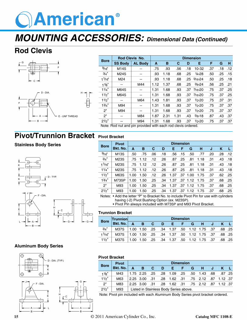
MOUNTING ACCESSORIES: Dimensional Data (Continued)
Rod Clevis
Pivot/Trunnion Bracket Pivot Bracket
Trunnion Bracket
Aluminum Body Series
Pivot Bracket
BoreRod Clevis No. Dimension
SS Body AL Body A B C D E F G H9/16" M14S -- .75 .93 .56 .18 10-32 .37 .18 .123/4" M24S -- .93 1.18 .68 .25 1/4-28 .50 .25 .15
11/16" M24 -- .93 1.18 .68 .25 5/16-24 .50 .25 .18
11/8" -- M44 1.12 1.37 .68 .25 3/8-24 .56 .25 .2111/4" M64S -- 1.31 1.68 .93 .37 7/16-20 .75 .37 .2511/2" M64S -- 1.31 1.68 .93 .37 7/16-20 .75 .37 .2511/2" -- M64 1.43 1.81 .93 .37 1/2-20 .75 .37 .3113/4" M94 -- 1.31 1.68 .93 .37 1/2-20 .75 .37 .37
2" M94 -- 1.31 1.68 .93 .37 1/2-20 .75 .37 .372" -- M84 1.87 2.31 1.31 .43 5/8-18 .87 .43 .37
21/2" -- M94 1.31 1.68 .93 .37 1/2-20 .75 .37 .37Note: Rod nut and pin provided with each rod clevis ordered.
Bore PivotBkt. No.
DimensionA B C D E F G H J K L
9/16" M13S .50 .75 .06 .18 .56 .15 .50 .77 .20 .28 .123/4" M23S .75 1.12 .12 .26 .87 .25 .81 1.18 .31 .43 .18
11/16" M23S .75 1.12 .12 .26 .87 .25 .81 1.18 .31 .43 .1811/4" M23S .75 1.12 .12 .26 .87 .25 .81 1.18 .31 .43 .1811/2" M63S 1.00 1.50 .12 .26 1.37 .37 1.00 1.75 .37 .62 .2513/4" M73SP 1.00 1.50 .25 .34 1.37 .37 1.12 1.75 .37 .68 .25
2" M93 1.00 1.50 .25 .34 1.37 .37 1.12 1.75 .37 .68 .2521/2" M93 1.00 1.50 .25 .34 1.37 .37 1.12 1.75 .37 .68 .25Notes: • Add the letter “P” to Bracket No. to include Pivot Pin for use with cylinders
having (-2) Pivot Bushing Option (ex. M23SP).• Pivot Pin always included with M73SP and M93 Pivot Bracket.
Bore TrunnionBkt. No.
DimensionA B C D E F G H J K L
3/4" M37S 1.00 1.50 .25 .34 1.37 .50 1.12 1.75 .37 .68 .25
11/16" M37S 1.00 1.50 .25 .34 1.37 .50 1.12 1.75 .37 .68 .2511/2" M37S 1.00 1.50 .25 .34 1.37 .50 1.12 1.75 .37 .68 .25
Bore PivotBkt. No.
DimensionA B C D E F G H J K L
11/8" M43 1.75 2.25 .25 .28 1.09 .25 .50 1.43 .68 .87 .2511/2" M63 2.25 3.00 .31 .28 1.62 .31 .75 2.12 .87 1.12 .37
2" M83 2.25 3.00 .31 .28 1.62 .31 .75 2.12 .87 1.12 .3721/2" M93 Listed in Stainless Body Series above.
Note: Pivot pin included with each Aluminum Body Series pivot bracket ordered.
Stainless Body Series
F
C
G
H
J
B
L
E - UNF THREAD
G
D - DIA.
A
F
D - TYP.
F - DIA.
K
K
G
CH
E
AB
CH
AB
D - DIA. (TYP.)
G
AB
L
JF - DIA.
K
E

16 © 2011 American Cylinder Co., Inc. Catalog MFC 1108-E
American Cylinder Co., Inc.
American Cylinder Co., Inc.Peotone, Illinois 60468-9116708/258-3935FAX 708/258-3980
http:\\www.ameristore.biz
ON THE INTERNET
E-MAIL: [email protected]
http:\\www.americancylinder.com
WarrantyAmerican Cylinder Co., Inc. warrants its products to be free from defects in material and workmanship under normal wear and service for a period of 3 years from date of shipment of the order. American Cylinder Company shall have no liability under this warranty if: 1) The product is used other than in accordance with specifications. 2) The product is subjected to abuse, negligence, accident, misapplication, or unintended use. 3) The product is manufactured to buyer’s specifi-cations.
Manufacturer’s liability shall be limited to allowance of credit or replacement of defective product. American Cylinder Company shall not be liable or responsible for injuries or damages to persons or property arising out of the use or operation of American Cylinder products.
THIS WARRANTY IS EXPRESSLY IN LIEU OF ALL OTHER WAR-RANTIES, EXPRESSED OR IMPLIED, INCLUDING ANY IMPLIED WARRANTY OF MERCHANTABILITY OR FITNESS FOR A PAR-TICULAR PURPOSE, LIABILITY FOR LOST PROFIT OR FOR INDI-RECT, INCIDENTAL, CONSEQUENTIAL OR COMMERCIAL LOSSES, AND OF ALL OTHER OBLIGATIONS OR LIABILITIES.
These conditions subject to change without notice.