˘ 1 - Phan An · PDF filen and now production of private MV/LV substations with MV metering....
18
Transcript of ˘ 1 - Phan An · PDF filen and now production of private MV/LV substations with MV metering....
2�3�4���5��
��������
����1��
-!!+
1
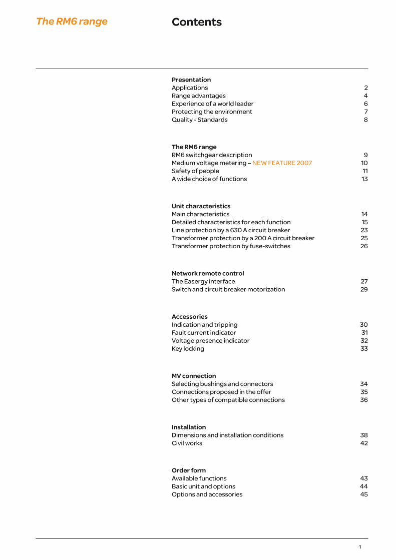
ContentsThe RM6 range
PresentationApplications 2Range advantages 4Experience of a world leader 6Protecting the environment 7Quality - Standards 8
The RM6 rangeRM6 switchgear description 9Medium voltage metering – NEW FEATURE 2007 10Safety of people 11A wide choice of functions 13
Unit characteristicsMain characteristics 14Detailed characteristics for each function 15Line protection by a 630 A circuit breaker 23Transformer protection by a 200 A circuit breaker 25Transformer protection by fuse-switches 26
Network remote controlThe Easergy interface 27Switch and circuit breaker motorization 29
AccessoriesIndication and tripping 30Fault current indicator 31Voltage presence indicator 32Key locking 33
MV connectionSelecting bushings and connectors 34Connections proposed in the offer 35Other types of compatible connections 36
InstallationDimensions and installation conditions 38Civil works 42
Order formAvailable functions 43Basic unit and options 44Options and accessories 45
11
Safety of peopleThe RM6 range05
5750
0557
4605
5752
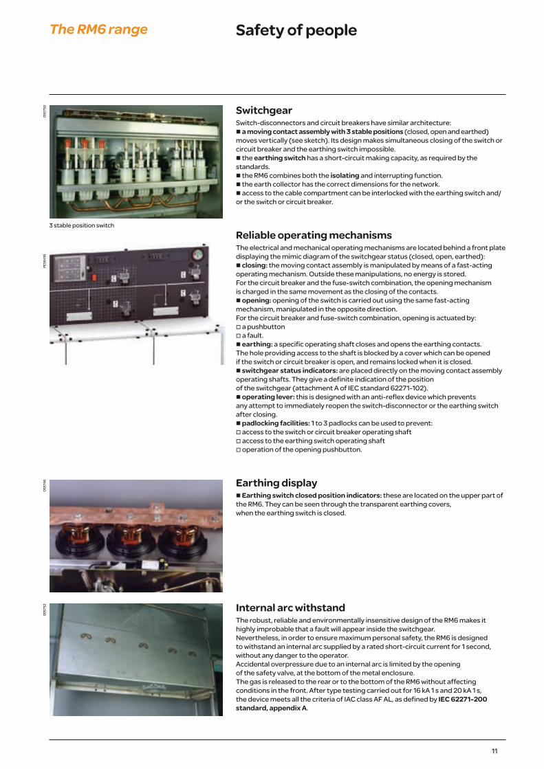
SwitchgearSwitch-disconnectors and circuit breakers have similar architecture:n a moving contact assembly with 3 stable positions (closed, open and earthed) moves vertically (see sketch). Its design makes simultaneous closing of the switch or circuit breaker and the earthing switch impossible.n the earthing switch has a short-circuit making capacity, as required by the standards.n the RM6 combines both the isolating and interrupting function.n the earth collector has the correct dimensions for the network.n access to the cable compartment can be interlocked with the earthing switch and/or the switch or circuit breaker.
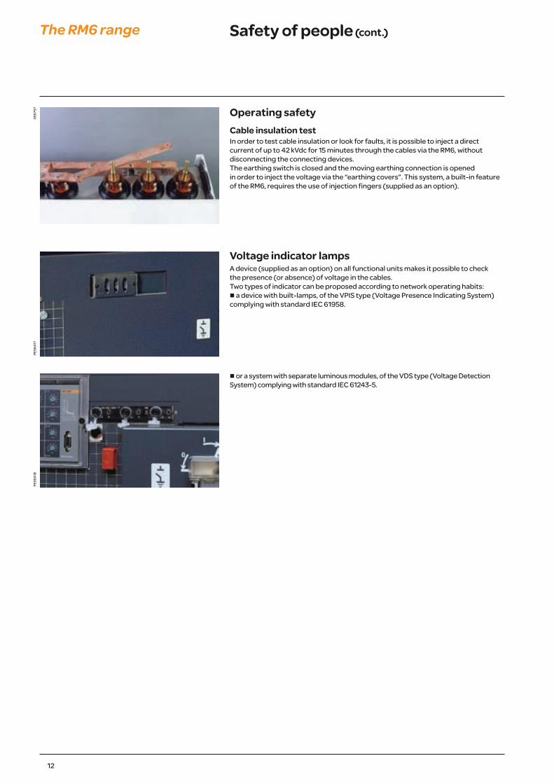
Reliable operating mechanismsThe electrical and mechanical operating mechanisms are located behind a front plate displaying the mimic diagram of the switchgear status (closed, open, earthed):n closing: the moving contact assembly is manipulated by means of a fast-acting operating mechanism. Outside these manipulations, no energy is stored.For the circuit breaker and the fuse-switch combination, the opening mechanism is charged in the same movement as the closing of the contacts.n opening: opening of the switch is carried out using the same fast-acting mechanism, manipulated in the opposite direction.For the circuit breaker and fuse-switch combination, opening is actuated by: o a pushbuttono a fault.n earthing: a specific operating shaft closes and opens the earthing contacts. The hole providing access to the shaft is blocked by a cover which can be opened if the switch or circuit breaker is open, and remains locked when it is closed.n switchgear status indicators: are placed directly on the moving contact assembly operating shafts. They give a definite indication of the position of the switchgear (attachment A of IEC standard 62271-102).n operating lever: this is designed with an anti-reflex device which prevents any attempt to immediately reopen the switch-disconnector or the earthing switch after closing.n padlocking facilities: 1 to 3 padlocks can be used to prevent:o access to the switch or circuit breaker operating shafto access to the earthing switch operating shafto operation of the opening pushbutton.
Earthing displayn Earthing switch closed position indicators: these are located on the upper part of the RM6. They can be seen through the transparent earthing covers, when the earthing switch is closed.
Internal arc withstandThe robust, reliable and environmentally insensitive design of the RM6 makes it highly improbable that a fault will appear inside the switchgear. Nevertheless, in order to ensure maximum personal safety, the RM6 is designed to withstand an internal arc supplied by a rated short-circuit current for 1 second, without any danger to the operator.Accidental overpressure due to an internal arc is limited by the opening of the safety valve, at the bottom of the metal enclosure. The gas is released to the rear or to the bottom of the RM6 without affecting conditions in the front. After type testing carried out for 16 kA 1 s and 20 kA 1 s, the device meets all the criteria of IAC class AF AL, as defined by IEC 62271-200 standard, appendix A.
PE56
416
3 stable position switch
12
Safety of people (cont.)The RM6 range05
5757
PE56
417
PE56
418
Operating safetyCable insulation testIn order to test cable insulation or look for faults, it is possible to inject a direct current of up to 42 kVdc for 15 minutes through the cables via the RM6, without disconnecting the connecting devices.The earthing switch is closed and the moving earthing connection is opened in order to inject the voltage via the “earthing covers”. This system, a built-in feature of the RM6, requires the use of injection fingers (supplied as an option).
Voltage indicator lampsA device (supplied as an option) on all functional units makes it possible to check the presence (or absence) of voltage in the cables.Two types of indicator can be proposed according to network operating habits:n a device with built-lamps, of the VPIS type (Voltage Presence Indicating System) complying with standard IEC 61958.
n or a system with separate luminous modules, of the VDS type (Voltage Detection System) complying with standard IEC 61243-5.

13
A wide choice of functionsThe RM6 range
RM6 range functionsThe RM6 range brings together all of the MV functions enabling:n connection, power supply and protection of transformers on a radial or open-ring network via 200 A circuit breakers with an independent protection chain or via combined fuse-switchesn protection of lines by a 630 A circuit breakern and now production of private MV/LV substations with MV metering.
Network switch Line feeder630 A circuit breaker
Transformer feeder200 A circuit breaker
Transformer feederCombined fuse-switch
DE5
7041
DE5
7042
DE5
7043
DE5
7044
I B D Q
Network couplingSwitch
Network coupling 630 A circuit breaker
Cable connection MV metering
DE5
7045
DE5
7046
DE5
7047
DE5
7048
IC BC O Mt
Device designationType of tank Multifunction configurations * Unit configurations
NE: non-extensible RE: extensible to the rightLE: extensible to the leftDE: extensible module to the right or left (one function)
I B D Q
I I B D Q
I I B D Q IC
BC O
Mtno. 4 no. 3 no. 2 no. 1 no. 1
Examples of designations
RM6 NE-DIDIRM6 RE-IDIRM6 NE-IQI
RM6 DE-IRM6 NE-DRM6 DE-Mt
(*) Refer to the table on page 43 for the choice of different combinations
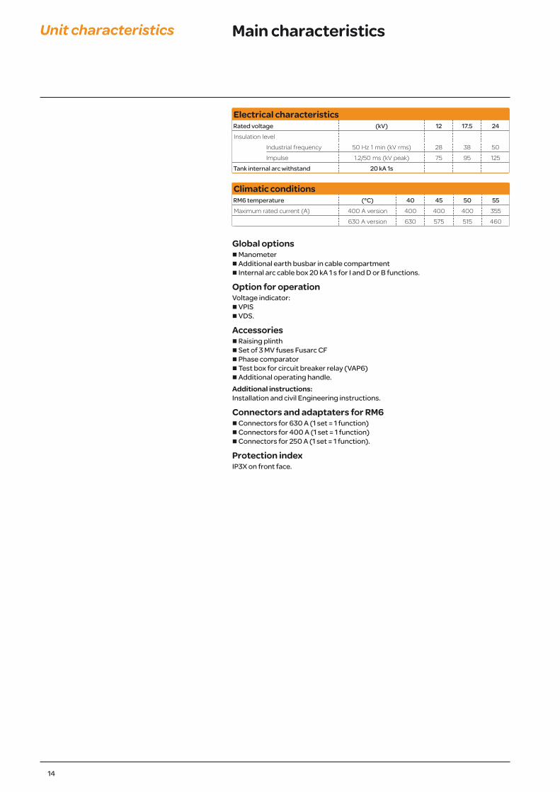
Electrical characteristics Rated voltage (kV) 12 17.5 24 Insulation level
Industrial frequency 50 Hz 1 min (kV rms) 28 38 50
Impulse 1.2/50 ms (kV peak) 75 95 125
Tank internal arc withstand 20 kA 1s
Climatic conditions RM6 temperature (°C) 40 45 50 55 Maximum rated current (A) 400 A version 400 400 400 355
630 A version 630 575 515 460
Global optionsn Manometern Additional earth busbar in cable compartment n Internal arc cable box 20 kA 1 s for I and D or B functions.
Option for operationVoltage indicator:n VPISn VDS.
Accessoriesn Raising plinthn Set of 3 MV fuses Fusarc CFn Phase comparatorn Test box for circuit breaker relay (VAP6)n Additional operating handle.Additional instructions:Installation and civil Engineering instructions.
Connectors and adaptaters for RM6n Connectors for 630 A (1 set = 1 function)n Connectors for 400 A (1 set = 1 function)n Connectors for 250 A (1 set = 1 function).
Protection indexIP3X on front face.
14
Main characteristicsUnit characteristics

18
Detailed characteristics for each function (cont.)
Unit characteristics
Transformer feeder with fuse-switch combinations (Q function)Rated voltage (kV) 12 12 17.5 24 24 24 24
Network switch (I function)Rated current (A) 630 630 630 400 400 630 630Breaking capacity (A) Charging current 630 630 630 400 400 630 630
Earth leakage fault 95 95 95 95 95 95 95No-load cable 30 30 30 30 30 30 30
Short-time withstand current (kA rms) 21 25 21 12.5 16 16 20Duration (s) 1 1 1 or 3 1 1 1 1 or 3
Making capacity of switchand earthing switches
(kA peak) 52.5 62.5 52.5 31.25 40 40 50
Bushing C C C B or C B or C C C
Transformer feeder with fuse-switch protection (Q function)Rated current (A) 200 200 200 200 200 200 200Off-load transformer laking capacity (A) 16 16 16 16 16 16 16Short-circuit breaking capacity (kA) 21 25 21 12.5 16 16 20Making capacity (kA peak) 52.5 62.5 52.5 31.25 40 40 50Bushing A A A A A A A
DE5
7014
Non-extensible switchgear
NE-QI NE-IQI NE-IIQI NE-QIQI
DE5
6462
Extensible switchgear to the right
RE-IQI RE-IIQI RE-QIQI
Accessories and optionsAuxiliary contacts aloneFor main switch position indication 2 NO - 2 NC and ESw 1 O/C(this option is included in remote operation option).Auxiliary contact for fuses blown Shunt trip coil for external tripping n 24 Vdcn 48/60 Vdcn 120 Vacn 110/125 Vdc - 220 Vacn 220 Vdc/380 Vac.Undervoltage coiln 24 Vdcn 48 Vdcn 125 Vdcn 110-230 Vac.Key locking devicesn Type R6n Type R7n Type R8.
Admin
Rectangle
Admin
Rectangle
Admin
Rectangle
26
Transformer protection by fuse-switches
Unit characteristics
Ratings for fuses for transformer protection depend, among other points, on the following criteria:n service voltagen transformer ratingn thermal dissipation of the fusesn fuse technology.Two types of fuse may be installed:n Solefuse type: according to UTE NFC 64210 standard, with or without striker,n Fusarc CF type: according to IEC 60282-1 dimensional standard, with or without striker.Example (using the selection table below) general case, for protection of a 400 kVA transformer at 10 kV, either Solefuse fuses with a rating of 63 A or Fusarc CF fuses with a rating of 50 A are chosen.
Correct operation of the RM6 is not guaranteed when using fuses from other manufacturers.
Selection table(Rating in A, no overload, –25°C < q < 40°C)
Fuse type Operating Transformer rating (kVA) Rated voltage 50 75 100 125 160 200 250 315 400 500 630 800 1000 1250 1600 2000 voltage (kV) (kV) Solefuse (UTE NFC standards: 13.100, 64.210)
5.5 16 31.5 31.5 63 63 63 63 63 7.210 16 16 31.5 31.5 31.5 63 63 63 63 2415 16 16 16 16 16 43 43 43 43 43 6320 16 16 16 16 16 16 43 43 43 43 43 63
Fusarc CF and SIBA (1) (General case, IEC 60282-1 standard, IEC 62271-105 (to replace IEC 60420) and DIN 43625 standard)3 20 31.5 40 50 50 63 80 100 125 (2) 160 (1) 12
3.3 20 25 40 40 40 63 80 80 125 (2) 125 (2) 160 (1)
4.2 20 25 25 40 50 50 63.5 80 80 100 125 (2) 160 (1)
5.5 16 20 25 25 40 40 50 63 80 80 100 125 (2) 160 (1)
6 16 20 25 25 31.5 40 50 50 63 80 100 125 (2) 160 (1)
6.6 10 20 25 25 31.5 40 50 50 63 63 80 100 125 (2) 160 (1)
10 10 10 16 20 25 25 31.5 40 50 50 63 80 100 125 (2)
11 10 10 16 20 20 25 25 40 40 50 50 63 80 100 125 (2)
13.8 10 10 10 16 16 20 25 31.5 40 40 50 50 63 100 (2) 2415 10 10 10 10 16 20 25 31.5 31.5 40 50 50 63 80 100 (2)
20 10 10 10 10 16 16 20 25 25 31.5 40 40 63 63 80 100 (2)
22 10 10 10 10 10 16 16 20 25 31.5 40 40 50 63 80 100 (2)
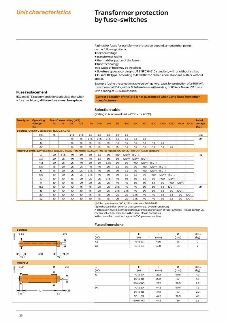
Fuse dimensionsSolefuse
DE5
5988 Ur
(kV)Ir
(A)L
(mm)Ø
(mm)Mass (kg)
7.2 16 to 63 450 55 224 16 to 63 450 55 2
Fusarc CF
DE5
5989 Ur
(kV)Ir
(A)L
(mm)Ø
(mm)Mass (kg)
12 10 to 20 292 50.5 1.225 to 40 292 57 1.5
50 to 100 292 78.5 2.824 10 to 20 442 50.5 1.6
25 to 40 442 57 2.250 to 63 442 78.5 4.1
80 to 100 442 88 5.3
(1) Siba type fuses at 160 A/12 kV reference 30-020-13(2) In the case of an external trip system (e.g.: overcurrent relay)A calculation must be carried out to guarantee coordination of fuse-switches – Please consult us.For any values not included in the table, please consult us.In the case of an overload beyond 40°C, please consult us.
Fuse replacementIEC and UTE recommendations stipulate that when a fuse has blown, all three fuses must be replaced.

34
MV connection Selecting bushings and connectors
Generaln The profiles, contacts and dimensions of the RM6 connection interfaces are defined by the IEC 60137 standard.n 100% of the epoxy resin interfaces undergo dielectric testing at power frequencyand partial discharge tests.
Appropriateness for useThe bushings carry the electrical current from the outside to the inside of the enclosure, which is filled with SF6 gas, ensuring insulation between the live conductors and the frame.There are 3 types of bushing, which are defined by their short-time withstand current:n Type A: 200 A: 12.5 kA 1 s and 31.5 kA peak (plug-in)n Type B: 400 A: 16 kA 1 s and 40 kA peak (plug-in)n Type C: 630 A: 25 kA 1 s, 20 kA 3 s and 62.5 kA peak (disconnectable M16).
How to define the connection interfaceThe connection interfaces depend on specific criteria, such as:
Installationn Current rating of the connected equipment: 200, 400, 630 An Short-time withstand current for 12.5 kA, 16 kA, 25 kA switch and circuit breakerfunctionsn For the fuse-switch combination function, as the short-circuit current is limited by the fuse, the connection interface will be of type A (200 A)n Minimum phase expansion lengthn Connection type:o plug in: multicontact ringo disconnectable: bolted.n Output position: straight, elbow.
Cablen Specified voltage:o of the cableo of the network.n Type of conductor:o aluminiumo copper.n Cross section in mm2
b Insulation diameterb Cable composition:o single-coreo 3-core.n Insulation type:o dryo paper impregnated (non-draining type).n Type of screenn Armature.
MT5
5039
Types of connection interface
This information must be specified for better definition of the connection interfaces.
35
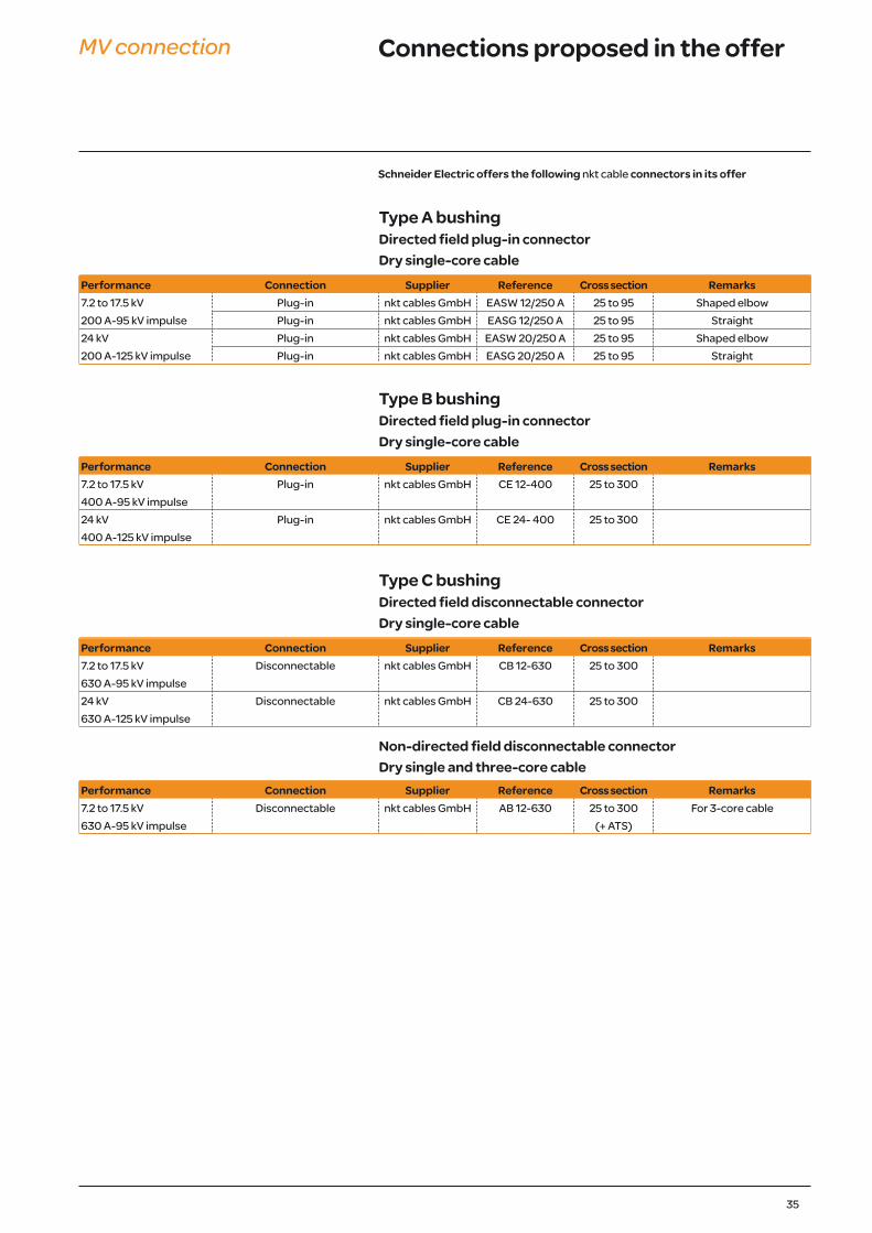
MV connection Connections proposed in the offer
Type A bushingDirected field plug-in connector Dry single-core cable
Performance Connection Supplier Reference Cross section Remarks 7.2 to 17.5 kV Plug-in nkt cables GmbH EASW 12/250 A 25 to 95 Shaped elbow 200 A-95 kV impulse Plug-in nkt cables GmbH EASG 12/250 A 25 to 95 Straight 24 kV Plug-in nkt cables GmbH EASW 20/250 A 25 to 95 Shaped elbow 200 A-125 kV impulse Plug-in nkt cables GmbH EASG 20/250 A 25 to 95 Straight
Type B bushingDirected field plug-in connector Dry single-core cable
Performance Connection Supplier Reference Cross section Remarks 7.2 to 17.5 kV Plug-in nkt cables GmbH CE 12-400 25 to 300 400 A-95 kV impulse 24 kV Plug-in nkt cables GmbH CE 24- 400 25 to 300 400 A-125 kV impulse
Type C bushingDirected field disconnectable connector Dry single-core cable
Performance Connection Supplier Reference Cross section Remarks 7.2 to 17.5 kV Disconnectable nkt cables GmbH CB 12-630 25 to 300 630 A-95 kV impulse 24 kV Disconnectable nkt cables GmbH CB 24-630 25 to 300 630 A-125 kV impulse
Non-directed field disconnectable connector Dry single and three-core cable
Performance Connection Supplier Reference Cross section Remarks 7.2 to 17.5 kV Disconnectable nkt cables GmbH AB 12-630 25 to 300 For 3-core cable 630 A-95 kV impulse (+ ATS)
Schneider Electric offers the following nkt cable connectors in its offer

36
Type A bushingDirected field plug-in connector Dry single-core cable
Performance Connection Supplier Reference Cross section Remarks 7.2 to 10 kV Plug-in Elastimold 158LR 16 to 120 T-shaped elbow 200 A-95 kV impulse 151SR 16 to 120 Straight, Q function only
Pirelli FMCE 250 16 to 95 7.2 to 24 kV Plug-in Elastimold K158LR 16 to 95 T-shaped elbow 200 A-125 kV impulse K151SR 25 to 95 Straight, Q function only
Type A/M8 bushingNon-directed field disconnectable connector (*) Dry single and three-core cable
Performance Connection Supplier Reference Cross section Remarks 7.2 to 17.5 kV Heat shrinkable Raychem EPKT+EAKT 16 to 150 200 A-95 kV impulse Insulating boots Kabeldon KAP70 70 max.
(*) 520 mm plinth must be used
Type B bushingDirected field plug-in connector Dry single-core cable
Performance Connection Supplier Reference Cross section Remarks 7.2 to 10 kV Plug-in Elastimold 400 LR 70 to 240 Limited to Us = 10 kV 400 A-95 kV impulse 24 kV Plug-in Pirelli FMCE 400 70 to 300 400 A-125 kV impulse Elastimold K400LR 35 to 240
Kabeldon SOC 630 50 to 300
Type C bushingDirected field disconnectable connector Dry single-core cable
Performance Connection Supplier Reference Cross section Remarks 7.2 to 10 kV Disconnectable Elastimold 440 TB 70 to 240 630 A-95 kV impulse 7.2 to 24 kV Disconnectable Pirelli FMCTs 400 70 to 300 630 A-125 kV impulse Elastimold K400TB 35 to 240
Kabeldon SOC 630 50 to 300
Non-directed field disconnectable connector Dry single and three-core cable
Performance Connection Supplier Reference Cross section Remarks 7.2 to 17.5 kV Heat shrinkable Raychem EPKT+EAKT 16 to 300 630 A-95 kV impulse Sigmaform Q-CAP 16 to 300
Insulating boots Kabeldon SOC 630 50 to 300 Completed by a kit for three-pole cable
Pirelli ELPB12 50 to 300 Limited to 75 kV impulseSimplified disconnectable Raychem RICS - EPKT 25 to 300
Euromold 15TS-NSS 50 to 300 Limited to Us = 12 kV 24 kV Simplified disconnectable Raychem RICS - EPKT 25 to 300 630 A-125 kV impulse
MV connection Other types of compatible connections
37
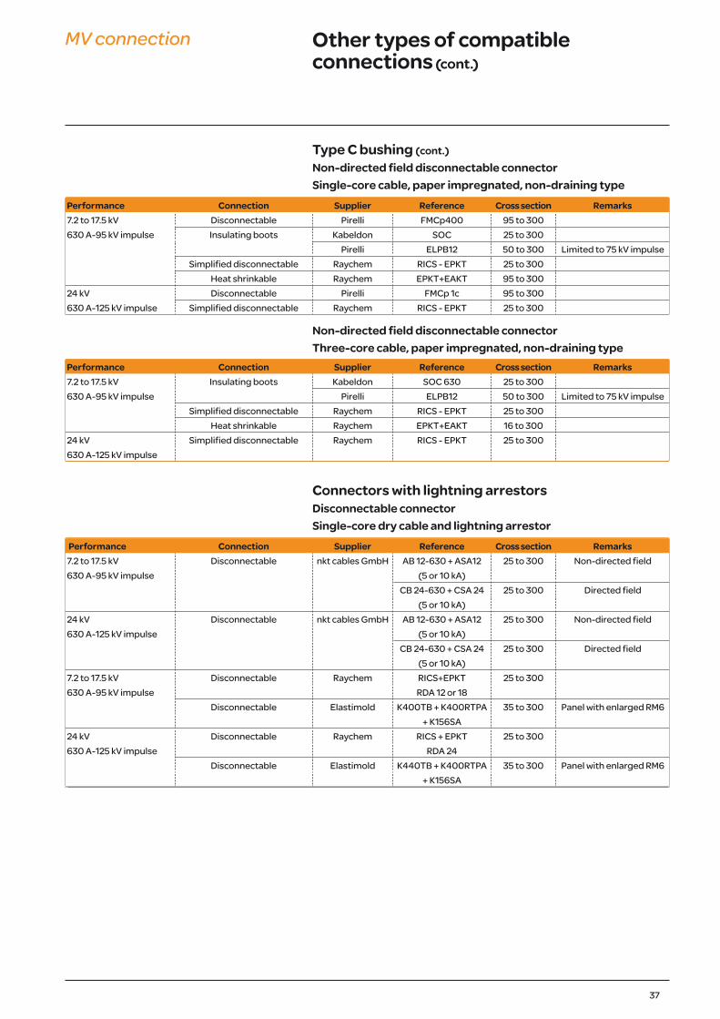
Type C bushing (cont.)Non-directed field disconnectable connector Single-core cable, paper impregnated, non-draining type
Performance Connection Supplier Reference Cross section Remarks 7.2 to 17.5 kV Disconnectable Pirelli FMCp400 95 to 300 630 A-95 kV impulse Insulating boots Kabeldon SOC 25 to 300
Pirelli ELPB12 50 to 300 Limited to 75 kV impulseSimplified disconnectable Raychem RICS - EPKT 25 to 300
Heat shrinkable Raychem EPKT+EAKT 95 to 300 24 kV Disconnectable Pirelli FMCp 1c 95 to 300 630 A-125 kV impulse Simplified disconnectable Raychem RICS - EPKT 25 to 300
Non-directed field disconnectable connector Three-core cable, paper impregnated, non-draining type
Performance Connection Supplier Reference Cross section Remarks 7.2 to 17.5 kV Insulating boots Kabeldon SOC 630 25 to 300 630 A-95 kV impulse Pirelli ELPB12 50 to 300 Limited to 75 kV impulse
Simplified disconnectable Raychem RICS - EPKT 25 to 300Heat shrinkable Raychem EPKT+EAKT 16 to 300
24 kV Simplified disconnectable Raychem RICS - EPKT 25 to 300 630 A-125 kV impulse
Connectors with lightning arrestorsDisconnectable connector Single-core dry cable and lightning arrestor
Performance Connection Supplier Reference Cross section Remarks 7.2 to 17.5 kV Disconnectable nkt cables GmbH AB 12-630 + ASA12 25 to 300 Non-directed field 630 A-95 kV impulse (5 or 10 kA)
CB 24-630 + CSA 24 25 to 300 Directed field(5 or 10 kA)
24 kV Disconnectable nkt cables GmbH AB 12-630 + ASA12 25 to 300 Non-directed field 630 A-125 kV impulse (5 or 10 kA)
CB 24-630 + CSA 24 25 to 300 Directed field(5 or 10 kA)
7.2 to 17.5 kV Disconnectable Raychem RICS+EPKT 25 to 300 630 A-95 kV impulse RDA 12 or 18
Disconnectable Elastimold K400TB + K400RTPA 35 to 300 Panel with enlarged RM6+ K156SA
24 kV Disconnectable Raychem RICS + EPKT 25 to 300 630 A-125 kV impulse RDA 24
Disconnectable Elastimold K440TB + K400RTPA 35 to 300 Panel with enlarged RM6+ K156SA
MV connection Other types of compatible connections (cont.)
38
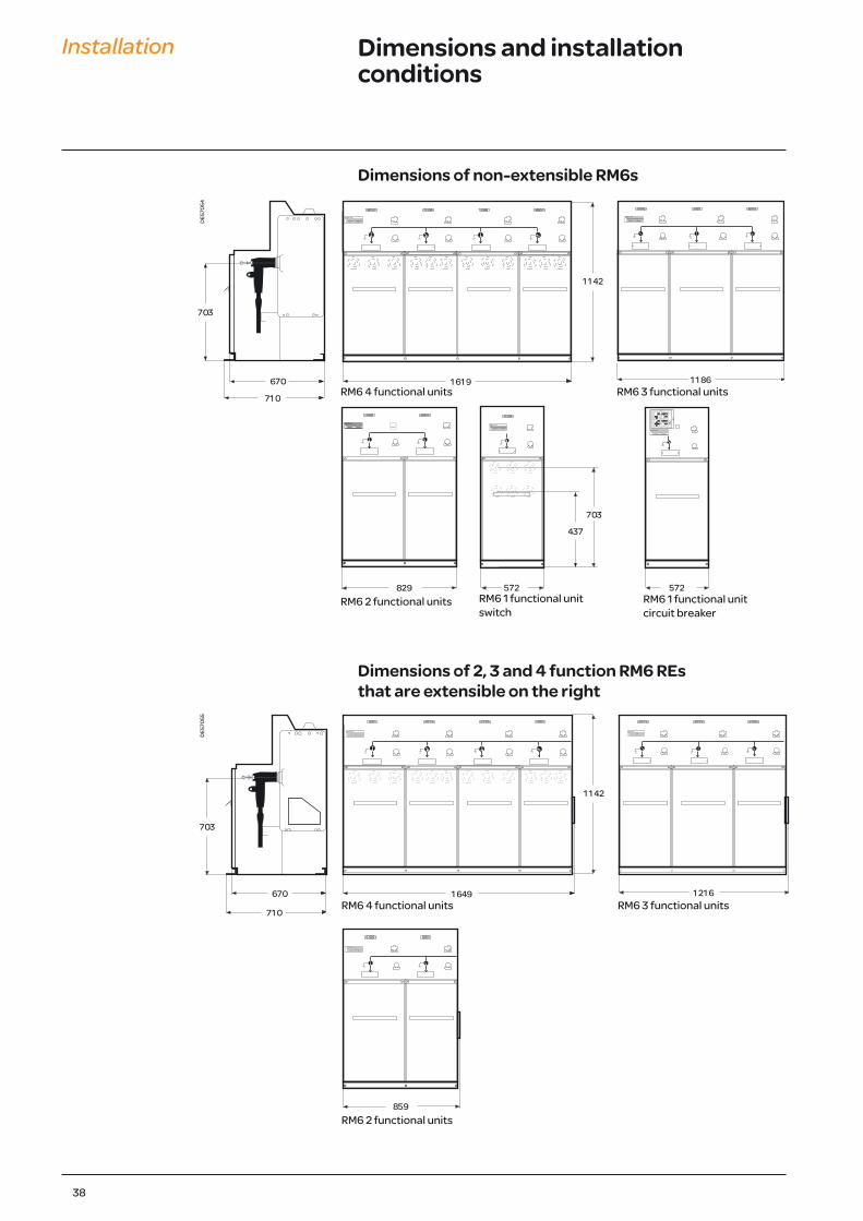
Installation Dimensions and installation conditions
Dimensions of non-extensible RM6s
Dimensions of 2, 3 and 4 function RM6 REs that are extensible on the right
DE5
7054
DE5
7055
RM6 4 functional units RM6 3 functional units
RM6 2 functional units RM6 1 functional unit switch
RM6 1 functional unitcircuit breaker
RM6 4 functional units RM6 3 functional units
RM6 2 functional units
41
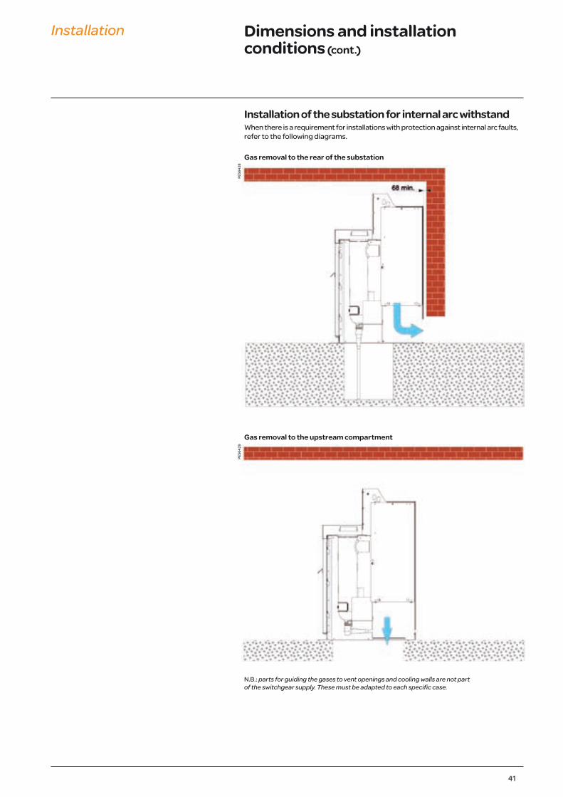
Installation Dimensions and installation conditions (cont.)
Installation of the substation for internal arc withstandWhen there is a requirement for installations with protection against internal arc faults, refer to the following diagrams.
Gas removal to the rear of the substation
Gas removal to the upstream compartment
N.B.: parts for guiding the gases to vent openings and cooling walls are not part of the switchgear supply. These must be adapted to each specific case.
PE56
428
PE56
429
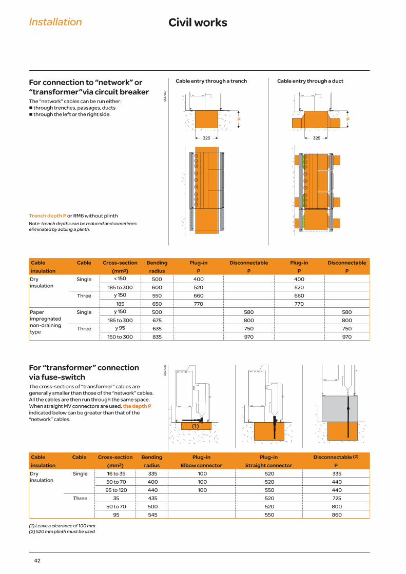
Cable Cable Cross-section Bending Plug-in Disconnectable Plug-in Disconnectableinsulation (mm2) radius P P P P
Dry insulation
Single < 150 500 400 400185 to 300 600 520 520
Three y 150 550 660 660185 650 770 770
Paper impregnated non-draining type
Single y 150 500 580 580185 to 300 675 800 800
Three y 95 635 750 750150 to 300 835 970 970
42
Installation Civil works
For connection to “network” or “transformer”via circuit breakerThe “network” cables can be run either:n through trenches, passages, ductsn through the left or the right side.
Trench depth P or RM6 without plinthNote: trench depths can be reduced and sometimes eliminated by adding a plinth.
DE5
7027
DE5
7028
Cable entry through a trench Cable entry through a duct
For “transformer” connection via fuse-switchThe cross-sections of “transformer” cables are generally smaller than those of the “network” cables.All the cables are then run through the same space.When straight MV connectors are used, the depth P indicated below can be greater than that of the“network” cables.
Cable Cable Cross-section Bending Plug-in Plug-in Disconnectable (2)
insulation (mm2) radius Elbow connector Straight connector P Dry insulation
Single 16 to 35 335 100 520 33550 to 70 400 100 520 440
95 to 120 440 100 550 440Three 35 435 520 725
50 to 70 500 520 80095 545 550 860
(1) Leave a clearance of 100 mm(2) 520 mm plinth must be used
43
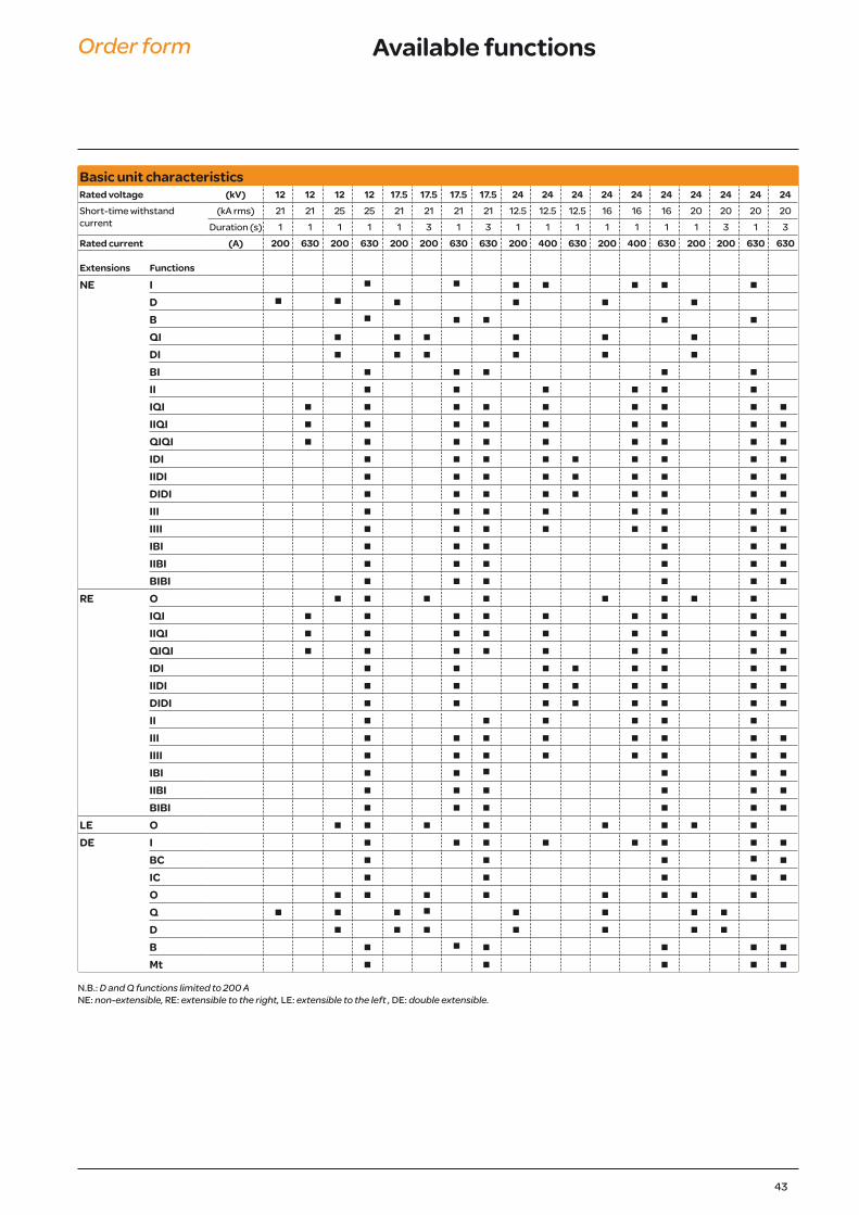
Order form Available functions
Basic unit characteristics Rated voltage (kV) 12 12 12 12 17.5 17.5 17.5 17.5 24 24 24 24 24 24 24 24 24 24 Short-time withstand current
(kA rms) 21 21 25 25 21 21 21 21 12.5 12.5 12.5 16 16 16 20 20 20 20Duration (s) 1 1 1 1 1 3 1 3 1 1 1 1 1 1 1 3 1 3
Rated current (A) 200 630 200 630 200 200 630 630 200 400 630 200 400 630 200 200 630 630
Extensions Functions
NE I n n n n n n n D n n n n n n B n n n n n QI n n n n n n DI n n n n n n BI n n n n n II n n n n n n IQI n n n n n n n n n IIQI n n n n n n n n n QIQI n n n n n n n n n IDI n n n n n n n n n IIDI n n n n n n n n n DIDI n n n n n n n n n III n n n n n n n n IIII n n n n n n n n IBI n n n n n n IIBI n n n n n n BIBI n n n n n n
RE O n n n n n n n n IQI n n n n n n n n n IIQI n n n n n n n n n QIQI n n n n n n n n n IDI n n n n n n n n IIDI n n n n n n n n DIDI n n n n n n n n II n n n n n n III n n n n n n n n IIII n n n n n n n n IBI n n n n n n IIBI n n n n n n BIBI n n n n n n
LE O n n n n n n n n DE I n n n n n n n n
BC n n n n n IC n n n n n O n n n n n n n n Q n n n n n n n n D n n n n n n n B n n n n n n Mt n n n n n
N.B.: D and Q functions limited to 200 ANE: non-extensible, RE: extensible to the right, LE: extensible to the left , DE: double extensible.
44
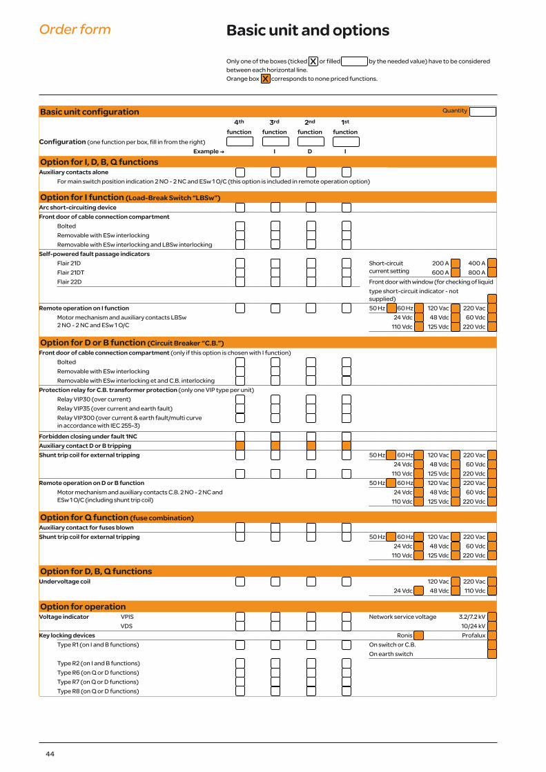
Order form Basic unit and options
Basic unit configuration Quantity
4th 3rd 2nd 1st
function function function functionConfiguration (one function per box, fill in from the right)
Example ; I D I
Option for I, D, B, Q functionsAuxiliary contacts alone
For main switch position indication 2 NO - 2 NC and ESw 1 O/C (this option is included in remote operation option)
Option for I function (Load-Break Switch “LBSw”)Arc short-circuiting device Front door of cable connection compartment
BoltedRemovable with ESw interlockingRemovable with ESw interlocking and LBSw interlocking
Self-powered fault passage indicatorsFlair 21D Short-circuit
current setting200 A 400 A
Flair 21DT 600 A 800 AFlair 22D Front door with window (for checking of liquid
type short-circuit indicator - not supplied)
Remote operation on I function 50 Hz 60 Hz 120 Vac 220 VacMotor mechanism and auxiliary contacts LBSw 2 NO - 2 NC and ESw 1 O/C
24 Vdc 48 Vdc 60 Vdc110 Vdc 125 Vdc 220 Vdc
Option for D or B function (Circuit Breaker “C.B.”)Front door of cable connection compartment (only if this option is chosen with I function)
BoltedRemovable with ESw interlockingRemovable with ESw interlocking et and C.B. interlocking
Protection relay for C.B. transformer protection (only one VIP type per unit)Relay VIP30 (over current)Relay VIP35 (over current and earth fault)Relay VIP300 (over current & earth fault/multi curve in accordance with IEC 255-3)
Forbidden closing under fault 1NC Auxiliary contact D or B tripping Shunt trip coil for external tripping 50 Hz 60 Hz 120 Vac 220 Vac
24 Vdc 48 Vdc 60 Vdc110 Vdc 125 Vdc 220 Vdc
Remote operation on D or B function 50 Hz 60 Hz 120 Vac 220 VacMotor mechanism and auxiliary contacts C.B. 2 NO - 2 NC and ESw 1 O/C (including shunt trip coil)
24 Vdc 48 Vdc 60 Vdc110 Vdc 125 Vdc 220 Vdc
Option for Q function (fuse combination)Auxiliary contact for fuses blown Shunt trip coil for external tripping 50 Hz 60 Hz 120 Vac 220 Vac
24 Vdc 48 Vdc 60 Vdc110 Vdc 125 Vdc 220 Vdc
Option for D, B, Q functionsUndervoltage coil 120 Vac 220 Vac
24 Vdc 48 Vdc 110 Vdc
Option for operationVoltage indicator VPIS Network service voltage 3.2/7.2 kV
VDS 10/24 kVKey locking devices Ronis Profalux
Type R1 (on I and B functions) On switch or C.B. On earth switchType R2 (on I and B functions)Type R6 (on Q or D functions)Type R7 (on Q or D functions)Type R8 (on Q or D functions)
Only one of the boxes (ticked or filled by the needed value) have to be considered between each horizontal line.Orange box corresponds to none priced functions.
xx

45
Order form Options and accessories
Specific option for one functionBushing for I function
Plug in 400 A type BBolted M16 screw type C (compulsory with 17.5 or 24 kV-630 A)Bolted 5/8" ANSI
Bushing for D functionPlug in 200 A type A (limited to 12.5 kA 1 s)Plug in 400 A type B (limited to 16 kA 1 s)Bolted M16 screw type C (compulsory with 17.5 or 24 kV-630 A)Bushing well ANSI (limited to 12.5 kA 1 s)
Bushing for B functionBolted M16 type CBolted 5/8" ANSI
Bushing for Q functionPlug in 200 AHeat shrinkable terminal for fuse chamber
Cable type for I function Single core Three-core Bottom plate in cable compartment (compulsory in case of three-core cable)
Cable type for D or B function Single core Three-core Bottom plate in cable compartment (compulsory in case of three-core cable)
In and fuse type for Q function 6 kV 10 kV 12/24 kV & 10/100 A(fuses to be procured separately 16 to 100 A 125 A
Global optionManometer Without Arabic Standard ScandinavianLightning arrestor on incoming functions (unable to coexist with internal arc cable box and only Elastimold)Additional earth busbar in cable compartment(compulsory if earth fault > 6 kA 1 s)Internal arc cable box 20 kA 1 s for I and D or B functions(unable to coexist with short-circuit indicator liquid type)
AccessoriesRaising plinth h = 260 mm h = 520 mmSet of 3 MV fuses Fusarc CF Rating (A)Phase comparatorTest box for circuit breaker relay (VAP 6)Additional operating handle Operating handle Enlarged operating handleAdditional instructions Installation and civil engineering instructions French English
Connectors and adaptaters for RM6 Quantity
Connectors for 630 A (1 set = 1 function)Directed field disconnectable connector
CB 24-630 ACB 24-630 A with CC-630 A (coupling connection)
Non-directed field disconnectable connectorAB 15-630 AAB 15-630 A with AC 15-630 A (coupling connection)
Connectors for 400 A (1 set = 1 function)Directed field plug-in connector CE 24-400 A
Connectors for 250 A (1 set = 1 function)Elbow connector EASW 20-250 AStraight connector EASG 20-250 A
Only one of the boxes (ticked or filled by the needed value) have to be considered between each horizontal line.Orange box corresponds to none priced functions.
xx