– 1 – Data Converters Data Converter BasicsProfessor Y. Chiu EECT 7327Fall 2014 Data Converter...
39
– 1 – Data Converters Data Converter Basics Professor Y. Chiu EECT 7327 Fall 2014 Data Converter Basics
-
Upload
janice-henry -
Category
Documents
-
view
228 -
download
1
Transcript of – 1 – Data Converters Data Converter BasicsProfessor Y. Chiu EECT 7327Fall 2014 Data Converter...
– 1 –
Data Converters Data Converter BasicsProfessor Y. Chiu
EECT 7327Fall 2014
Data Converter Basics

A/D and D/A Conversion
– 2 –
Data Converters Data Converter BasicsProfessor Y. Chiu
EECT 7327Fall 2014
S/H
Analogin
Digitalout
Quantization
DSP
AAF
S/H
Analogout
Digitalin
D/A
DSP
Smoothingfilter
A/D Conversion
D/A Conversion

Quantization
– 3 –
Data Converters Data Converter BasicsProfessor Y. Chiu
EECT 7327Fall 2014
N in
outFS
VDivision : D = 2
V
• Quantization = division + normalization + truncation
• Full-scale range (VFS) is determined by Vref
A/Dbn
Digital outputAnalog input
b1
...
Vref

Quantization Error
– 4 –
Data Converters Data Converter BasicsProfessor Y. Chiu
EECT 7327Fall 2014
FSout in out inN
Vε =D Δ - V =D - V
2
FSN
VΔ = =LSB
2
in FSV 0, V
Δ Δ
- ε2 2
Dout
0
Vin
Δ 2Δ 3Δ
1
3
5
0
2
4
6
7
VFS
2
-Δ-2Δ-3Δ
VFS
2
“Random” quantization error is usually regarded as noise
ε
Vin0
-Δ/2
Δ/2
Δ 2Δ 3Δ0-Δ-2Δ-3Δ
N = 3

Quantization Noise
– 5 –
Data Converters Data Converter BasicsProfessor Y. Chiu
EECT 7327Fall 2014
ε
Vin
Δ 2Δ 3Δ
0
4Δ 5Δ 6Δ 7Δ-Δ/2
Δ/2
VFS
Δ/2 2
2 2ε
-Δ/2
1 Δσ = ε dε =
Δ 12
Pε
0-Δ/2 Δ/2ε
1/Δ
Assumptions:• N is large
• 0 ≤ Vin ≤ VFS and Vin >> Δ
• Vin is active
• ε is Uniformly distributed• Spectrum of ε is white
Ref: W. R. Bennett, “Spectra of quantized signals,” Bell Syst. Tech. J., vol. 27, pp. 446-472, July 1948.
Signal-to-Quantization Noise Ratio (SQNR)
– 6 –
Data Converters Data Converter BasicsProfessor Y. Chiu
EECT 7327Fall 2014
2N22NFS
22ε
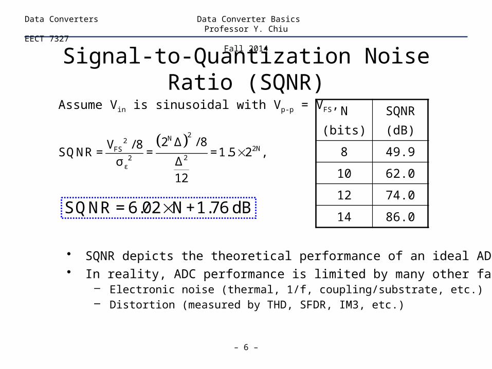
2 Δ / 8V / 8SQNR = = =1.5 2 ,
Δσ12
Assume Vin is sinusoidal with Vp-p = VFS,
SQNR = 6.02 N+1.76 dB
N(bits)
SQNR(dB)
8 49.9
10 62.0
12 74.0
14 86.0
• SQNR depicts the theoretical performance of an ideal ADC• In reality, ADC performance is limited by many other factors:
– Electronic noise (thermal, 1/f, coupling/substrate, etc.)– Distortion (measured by THD, SFDR, IM3, etc.)

FFT Spectrum of Quantized Signal
– 7 –
Data Converters Data Converter BasicsProfessor Y. Chiu
EECT 7327Fall 2014
• N = 10 bits
• 8192 samples, only
f = [0, fs/2] shown
• Normalized to Vin
• fs = 8192, fin = 779
• fin and fs must be
incommensurate
0 500 1000 1500 2000 2500 3000 3500 4000-120
-100
-80
-60
-40
-20
0
PSD
Frequency
dB
SQNR -1.76 dBENOB =
6.02 dB
SQNR = 61.93 dB
ENOB = 9.995 bits
Ref: W. R. Bennett, “Spectra of quantized signals,” Bell Syst. Tech. J., vol. 27, pp. 446-472, July 1948.

Commensurate fs and fin
– 8 –
Data Converters Data Converter BasicsProfessor Y. Chiu
EECT 7327Fall 2014
0 500 1000 1500 2000 2500 3000 3500 4000-120
-100
-80
-60
-40
-20
0
PSD
Frequency
dB
0 500 1000 1500 2000 2500 3000 3500 4000-120
-100
-80
-60
-40
-20
0
PSD
FrequencydB
fs = 8192fin = 256
fs = 8192fin = 2048
• Periodic sampling points result in periodic quantization errors• Periodic quantization errors result in harmonic distortion

Spectrum Leakage
– 9 –
Data Converters Data Converter BasicsProfessor Y. Chiu
EECT 7327Fall 2014
0 500 1000 1500 2000 2500 3000 3500 4000-120
-100
-80
-60
-40
-20
0
PSD
FrequencydB
0 500 1000 1500 2000 2500 3000 3500 4000-120
-100
-80
-60
-40
-20
0
PSD
Frequency
dB
fs = 8192fin = 779.3
fs = 8192fin = 779.3
• TD samples must include integer number of cycles of input signal• Windowing can be applied to eliminate spectrum leakage• Trade-off b/t main-lobe width and sideband rejection for different windows
w/Blackmanwindow

FFT Spectrum with Distortion
– 10 –
Data Converters Data Converter BasicsProfessor Y. Chiu
EECT 7327Fall 2014
0 500 1000 1500 2000 2500 3000 3500 4000-120
-100
-80
-60
-40
-20
0
PSD
Frequency
dB
• High-order harmonics are aliased back, visible in [0, fs/2] band
• E.g., HD3 @ 779x3+1=2338, HD9 @ 8192-9x779+1=1182
HD3HD9

Dynamic Performance
– 11 –
Data Converters Data Converter BasicsProfessor Y. Chiu
EECT 7327Fall 2014
SNDR[dB]
Vin
[dB]0 VFS
Overload
• Peak SNDR limited by large-signal distortion of the converter• Dynamic range implies the “theoretical” SNR of the converter
2in
10 2 2N
in
SNR
V / 2=10LOG
Δ /12+σ
V dB
PeakSNDR
Dynamic range
Circuitnoise
Dynamic Performance Metrics
– 12 –
Data Converters Data Converter BasicsProfessor Y. Chiu
EECT 7327Fall 2014
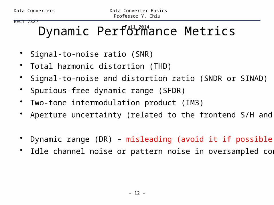
• Signal-to-noise ratio (SNR)
• Total harmonic distortion (THD)
• Signal-to-noise and distortion ratio (SNDR or SINAD)
• Spurious-free dynamic range (SFDR)
• Two-tone intermodulation product (IM3)
• Aperture uncertainty (related to the frontend S/H and clock)
• Dynamic range (DR) – misleading (avoid it if possible!)
• Idle channel noise or pattern noise in oversampled converters

Evaluating Dynamic Performance
– 13 –
Data Converters Data Converter BasicsProfessor Y. Chiu
EECT 7327Fall 2014
0 500 1000 1500 2000 2500 3000 3500 4000-120
-100
-80
-60
-40
-20
0
PSD
Frequency
dB
• Signal-to-noise
plus distortion ratio
(SNDR)
• Total harmonic
distortion (THD)
• Spurious-free
dynamic range
(SFDR)
SNDR = 59.16 dB
THD = 63.09 dB
SFDR = 64.02 dB
ENOB = 9.535 bits
HD3HD9
SNDR -1.76 dBENOB =
6.02 dB

Static Performance Metrics
– 14 –
Data Converters Data Converter BasicsProfessor Y. Chiu
EECT 7327Fall 2014
• Offset (OS)
• Gain error (GE)
• Monotonicity
• Linearity (unique to converters)– Differential nonlinearity (DNL)– Integral nonlinearity (INL)

– 15 –
Data Converters Data Converter BasicsProfessor Y. Chiu
EECT 7327Fall 2014
Static Performanceof DAC

DAC Transfer Characteristic
– 16 –
Data Converters Data Converter BasicsProfessor Y. Chiu
EECT 7327Fall 2014
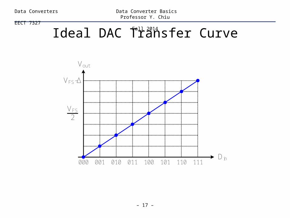
Note: Vout (bi = 1, for all i) = VFS - Δ = VFS(1-2-N) ≠ VFS
N N
N-iiout FS ii
i=1 i=1
bV = V = Δ b 2
2
D/Abn
Digital input
Vout
Analog output
b1
...
Vref
• N = # of bits
• VFS = Full-scale input
• Δ = VFS/2N = 1LSB
• bi = 0 or 1
• Multiplication
Ideal DAC Transfer Curve
– 17 –
Data Converters Data Converter BasicsProfessor Y. Chiu
EECT 7327Fall 2014
Vout
000Din
001 011 101010 100 110 111
VFS-Δ
VFS
2

Offset
– 18 –
Data Converters Data Converter BasicsProfessor Y. Chiu
EECT 7327Fall 2014
Vout
000Din
001 011 101010 100 110 111
VFS
2
VFS-Δ
Vos

Gain Error
– 19 –
Data Converters Data Converter BasicsProfessor Y. Chiu
EECT 7327Fall 2014
Vout
000Din
001 011 101010 100 110 111
VFS
2
VFS-Δ

Monotonicity
– 20 –
Data Converters Data Converter BasicsProfessor Y. Chiu
EECT 7327Fall 2014
Vout
000Din
001 011 101010 100 110 111
VFS
2
VFS-Δ
Differential and Integral Nonlinearities
– 21 –
Data Converters Data Converter BasicsProfessor Y. Chiu
EECT 7327Fall 2014
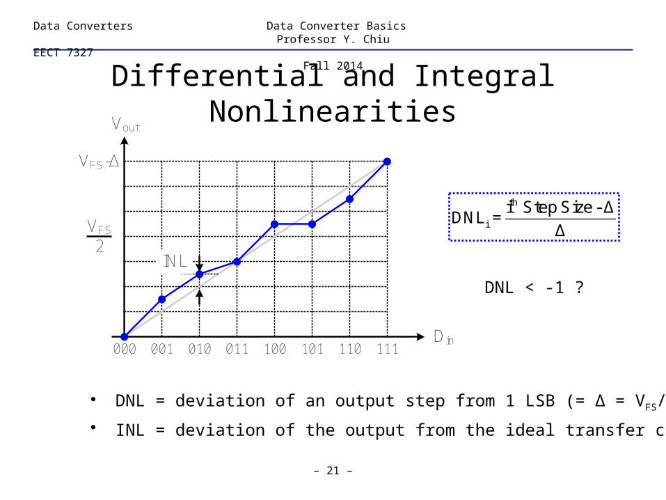
• DNL = deviation of an output step from 1 LSB (= Δ = VFS/2N)
• INL = deviation of the output from the ideal transfer curve
DNL < -1 ?
Vout
000Din
001 011 101010 100 110 111
VFS
2INL
VFS-Δ
th
i
i Step Size - ΔDNL =
Δ

DNL and INL
– 22 –
Data Converters Data Converter BasicsProfessor Y. Chiu
EECT 7327Fall 2014
Vout
000Din
001 011 101010 100 110 111
VFS
2
VFS-Δ
i
i jj=0
INL = DNL
INL = cumulative sum of DNL

DNL and INL
– 23 –
Data Converters Data Converter BasicsProfessor Y. Chiu
EECT 7327Fall 2014
• DNL measures the uniformity of quantization steps, or incremental (local) nonlinearity; small input signals are sensitive to DNL.
• INL measures the overall, or cumulative (global) nonlinearity; large input signals are often sensitive to both INL (HD) and DNL (QE).
Vout
000Din
001 011 101010 100 110 111
VFS
2
VFS-Δ
Vout
000Din
001 011 101010 100 110 111
VFS
2
VFS-Δ
Smooth Noisy

Measure DNL and INL (Method I)
– 24 –
Data Converters Data Converter BasicsProfessor Y. Chiu
EECT 7327Fall 2014
Vout
000Din
001 011 101010 100 110 111
VFS
2
VFS-Δ
Endpoints of the transfer characteristic are always at 0 and VFS-Δ
Endpointstretch

Measure DNL and INL (Method II)
– 25 –
Data Converters Data Converter BasicsProfessor Y. Chiu
EECT 7327Fall 2014
Vout
000Din
001 011 101010 100 110 111
VFS
2
VFS-Δ
Least-squarefit and stretch
(“detrend”)
Endpoints of the transfer characteristic may not be at 0 and VFS-Δ

Measure DNL and INL
– 26 –
Data Converters Data Converter BasicsProfessor Y. Chiu
EECT 7327Fall 2014
Method I (endpoint stretch)
Σ(INL) ≠ 0
Method II (LS fit & stretch)
Σ(INL) = 0
Vout
000Din
001 011 101010 100 110 111
VFS
2
VFS-Δ
Vout
000Din
001 011 101010 100 110 111
VFS
2
VFS-Δ
– 27 –
Data Converters Data Converter BasicsProfessor Y. Chiu
EECT 7327Fall 2014
Static Performanceof ADC
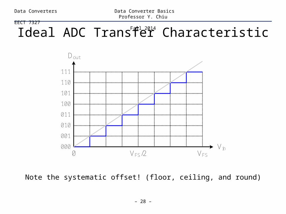
Ideal ADC Transfer Characteristic
– 28 –
Data Converters Data Converter BasicsProfessor Y. Chiu
EECT 7327Fall 2014
Dout
000 Vin
001
011
101
010
100
110
111
VFSVFS/20
Note the systematic offset! (floor, ceiling, and round)

DNL and Missing Code
– 29 –
Data Converters Data Converter BasicsProfessor Y. Chiu
EECT 7327Fall 2014
Dout
000 Vin
001
011
101
010
100
110
111
VFSVFS/20
DNL = deviation of an input step width from 1 LSB (= VFS/2N = Δ)
• DNL = ?• Can DNL < -1?
th
i
i Step Size - ΔDNL =
Δ
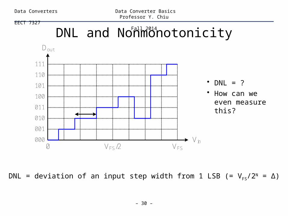
DNL and Nonmonotonicity
– 30 –
Data Converters Data Converter BasicsProfessor Y. Chiu
EECT 7327Fall 2014
Dout
000 Vin
001
011
101
010
100
110
111
VFSVFS/20
DNL = deviation of an input step width from 1 LSB (= VFS/2N = Δ)
• DNL = ?• How can we even
measure this?

INL
– 31 –
Data Converters Data Converter BasicsProfessor Y. Chiu
EECT 7327Fall 2014
Dout
000 Vin
001
011
101
010
100
110
111
VFSVFS/20
INL = deviation of the step midpoint from the ideal step midpoint
(method I and II …)
Any code• Missing?• Nonmonotonic?

10-bit ADC Example
– 32 –
Data Converters Data Converter BasicsProfessor Y. Chiu
EECT 7327Fall 2014
0 200 400 600 800 1000-2
-1
0
1
2DNL
LSB
0 200 400 600 800 1000-2
-1
0
1
2INL
Code
LSB
• 1024 codes
• No missing code!
• Plotted against the digital code, not Vin
• Code density test (CDT)
DNL must always be greater or equal to -1 LSB!

Code Density Test
– 33 –
Data Converters Data Converter BasicsProfessor Y. Chiu
EECT 7327Fall 2014
Cou
nt
000Vin
001 011 101010 100 110 111
VFS0
Uniformly distributed 0 ≤ Vin ≤ VFS
Δ
n
Δ
n
Δ
n
Δ
n
Δ
n
Δ
n
Δ
n
Δ
n
Ball casting problem: # of balls collected by each bin (ni) is proportional to the bin size (converter step size)
th
i ii
i
n - ni Step Size - ΔDNL =
Δ nC
ount
000Vin
001 011 101010 100 110 111
VFS0
Uniformly distributed 0 ≤ Vin ≤ VFS
>Δ
ni

CDT and Nonmonotonicity
– 34 –
Data Converters Data Converter BasicsProfessor Y. Chiu
EECT 7327Fall 2014
• Two transition steps for one code?! How to plot INL/DNL?
• CDT can be misleading in determining the static nonlinearity
Dout
000 Vin
001
011
101
010
100
110
111
VFSVFS/20

– 35 –
Data Converters Data Converter BasicsProfessor Y. Chiu
EECT 7327Fall 2014
Nyquist-Rate ADC

Nyquist-Rate ADC
– 36 –
Data Converters Data Converter BasicsProfessor Y. Chiu
EECT 7327Fall 2014
• Digitizes input signal up to Nyquist frequency (fN=fs/2)
• Minimum sample rate (fs) for a given input bandwidth
• Each sample is digitized to the maximum resolution of converter
• Often referred to as the “black box” version of digitization
A/Dbn
Digital outputAnalog input
b1...
Vref
fs

Nyquist-Rate ADC (N-Bit, Binary)
– 37 –
Data Converters Data Converter BasicsProfessor Y. Chiu
EECT 7327Fall 2014
• Word-at-a-time (1 step)† ← fast– Flash
• Level-at-a-time (2N steps) ← slowest– Integrating (Serial)
• Bit-at-a-time (N steps) ← slow– Successive approximation– Algorithmic (Cyclic)
• Partial word-at-a-time (1 < M ≤ N steps) ← medium– Subranging– Pipeline
• Others (1 ≤ M ≤ N step)– Folding ← relatively fast– Interleaving (of flash, pipeline, or SA) ← fastest
† the number in the parentheses is the “latency” of conversion, not “throughput”

Accuracy-Speed Tradeoff
– 38 –
Data Converters Data Converter BasicsProfessor Y. Chiu
EECT 7327Fall 2014
0
Resolution[Bits]
5
10
15
20
1k 10k 100k 1M 10M 100M 1G 10G
Sample Rate [Hz]
Nyquist
Oversampling
Integrating Oversampling
Successive ApproximationAlgorithmic
SubrangingPipelineFolding & Interpolating
FlashInterleaving
1 level/Tclk
1 word/OSR*Tclk
1 bit/Tclk
Partial word/Tclk
1 word/Tclk
100G

Building Blocks for Data Converters
– 39 –
Data Converters Data Converter BasicsProfessor Y. Chiu
EECT 7327Fall 2014
• Sample-and-Hold (Track-and-Hold) Amplifier
• Switched-Capacitor Amplifiers, Integrators, and Filters
• Operational Amplifier
• Comparators (Preamplifier and Latch)
• Voltage and Current DAC’s
• Current Sources
• Voltage/Current/Bandgap References