Unsteady Flow and Pressure Pulsation Characteristics...
6
Unsteady Flow and Pressure Pulsation Characteristics Analysis of Rotating Stall in Centrifugal Pumps under Off Design Conditions Xiaoran Zhao 1 , Zhengwei Wang 1 *, Yexiang Xiao 1 , Yongyao Luo 1 , Lei Cao 1 ISROMAC 2016 International Symposium on Transport Phenomena and Dynamics of Rotating Machinery Hawaii, Honolulu April 10-15, 2016 Abstract Unsteady flow phenomena like rotating stall frequently occur in centrifugal pumps under off design conditions. Rotating stall could lead to flow instabilities and pressure pulsation, which affect the normal operation of pumps. The mechanism of rotating stall has not been sufficiently understood in previous researches. This paper aims to simulate the unsteady flow characteristics in a centrifugal pump by CFD, analyze pressure pulsations caused by rotating stall and explore the propagation mechanism of rotating stall. In current study, 3D unsteady numerical simulations were performed to model the unsteady flow within the entire flow passage of a centrifugal pump under conditions of 0.4QBEP and 0.6QBEP. Though flow characteristics research, the generation and propagation of rotating stall are discovered. Additionally, frequencies and amplitudes of pressure pulsations related to rotating stall are investigated by spectrum analysis. Keywords Rotating Stall —Centrifugal Pumps —Pressure Pulsation 1 State Key Laboratory of Hydroscience and Engineering and Department of Thermal Engineering, Tsinghua University, Beijing, China *Corresponding author: [email protected] INTRODUCTION Centrifugal pumps are widely used in industry. To ensure efficient utilization, it is important to operate centrifugal pumps in stable conditions. Unsteady flow phenomena, including rotating stall, rotor-stator interaction (RSI) and reverse flows, exist in centrifugal pumps under off design conditions. All of above flow patterns could possibly lead to instabilities and pressure pulsations. During the past few years, rotor-stator interaction is regarded as the most important factor for strong pressure pulsations with blade passing frequency. Rotating stall is also a primary cause of low frequency pressure fluctuations in centrifugal pumps. When flow rate decreases sharply, flow separation develops, resulting to the passage blockage. This blockage will cause adjacent passage stalled, like the stall cell is propagating circumferentially. This phenomenon is called rotating stall. Rotating stall was firstly discovered and extensively studied in compressor turbines [1,2]. Much attention has been paid to the study on flow structures of rotating stall in pumps by both numerical and experimental methods. Yoshida [3] observed rotating stall in the vaned diffuser of a centrifugal pump in experiment. Sinha [4] described rotating stall phenomenon at the exit part of a centrifugal pump with vanned diffusers and revealed the relationship between rotating stall and pressure pulsation by PIV measurements. Sano [5] used CFD technology to explore rotating stall and pressure variation in a vaned diffuser of a pump and proved that the clearance between impeller and diffuser had an effect on occurrence regions of rotating stall. Recently, more researchers concentrate on rotating stall studies. Li [6] built an understanding on rotating stall in mixed flow pump and found that adverse pressure gradient in the flow passage increased with stall development and influenced stall in turn. Yuan [7] investigated broadband noise and resonance caused by rotating stall in a centrifugal pump under small flow rate condition though frequency analysis. Lucius [8] argued that rotating stall could excite structural vibrations in pumps through numerical simulations. Despite those studies, the mechanism of rotating stall has not been sufficiently understood in previous researches. In centrifugal turbomachinery research, both flow pattern study and pressure pulsation analysis are necessary. Cao [9] described three-dimensional turbulent flow in the entire flow passage of a shrouded centrifugal pump to understand energy losses caused by different factors. Yang [10] investigated vibration and noise generation mechanism of a double suction centrifugal fan based on analysis of the pressure fluctuations. The present paper applies CFD technology to simulate flow characteristics in a centrifugal pump, analyzes pressure pulsations caused by rotating stall and explores propagation mechanism of rotating stall. 1. Calculation Model 1.1 Parameters of Centrifugal Pump The studied model is a centrifugal pump with three impeller blades. Computational domains are showed in Figure 1, including volute, impeller and suction pipe. The main parameters of this pump are presented in Table 1.
Transcript of Unsteady Flow and Pressure Pulsation Characteristics...
Unsteady Flow and Pressure Pulsation Characteristics Analysis of Rotating Stall in Centrifugal Pumps under Off Design Conditions
Xiaoran Zhao1, Zhengwei Wang 1*, Yexiang Xiao1, Yongyao Luo1, Lei Cao1
ISROMAC 2016
International
Symposium on
Transport
Phenomena and
Dynamics of
Rotating Machinery
Hawaii, Honolulu
April 10-15, 2016
Abstract
Unsteady flow phenomena like rotating stall frequently occur in centrifugal pumps under off
design conditions. Rotating stall could lead to flow instabilities and pressure pulsation, which
affect the normal operation of pumps. The mechanism of rotating stall has not been sufficiently
understood in previous researches. This paper aims to simulate the unsteady flow characteristics
in a centrifugal pump by CFD, analyze pressure pulsations caused by rotating stall and explore
the propagation mechanism of rotating stall. In current study, 3D unsteady numerical simulations
were performed to model the unsteady flow within the entire flow passage of a centrifugal pump
under conditions of 0.4QBEP and 0.6QBEP. Though flow characteristics research, the generation
and propagation of rotating stall are discovered. Additionally, frequencies and amplitudes of
pressure pulsations related to rotating stall are investigated by spectrum analysis.
Keywords
Rotating Stall —Centrifugal Pumps —Pressure Pulsation
1 State Key Laboratory of Hydroscience and Engineering and Department of Thermal Engineering, Tsinghua University, Beijing, China
*Corresponding author: [email protected]
INTRODUCTION
Centrifugal pumps are widely used in industry. To ensure
efficient utilization, it is important to operate centrifugal
pumps in stable conditions. Unsteady flow phenomena,
including rotating stall, rotor-stator interaction (RSI) and
reverse flows, exist in centrifugal pumps under off design
conditions. All of above flow patterns could possibly lead to
instabilities and pressure pulsations. During the past few
years, rotor-stator interaction is regarded as the most
important factor for strong pressure pulsations with blade
passing frequency. Rotating stall is also a primary cause of
low frequency pressure fluctuations in centrifugal pumps.
When flow rate decreases sharply, flow separation
develops, resulting to the passage blockage. This
blockage will cause adjacent passage stalled, like the
stall cell is propagating circumferentially. This
phenomenon is called rotating stall. Rotating stall was
firstly discovered and extensively studied in compressor
turbines [1,2]. Much attention has been paid to the study
on flow structures of rotating stall in pumps by both
numerical and experimental methods. Yoshida [3]
observed rotating stall in the vaned diffuser of a
centrifugal pump in experiment. Sinha [4] described
rotating stall phenomenon at the exit part of a centrifugal
pump with vanned diffusers and revealed the
relationship between rotating stall and pressure
pulsation by PIV measurements. Sano [5] used CFD
technology to explore rotating stall and pressure
variation in a vaned diffuser of a pump and proved that
the clearance between impeller and diffuser had an
effect on occurrence regions of rotating stall.
Recently, more researchers concentrate on rotating stall
studies. Li [6] built an understanding on rotating stall in
mixed flow pump and found that adverse pressure
gradient in the flow passage increased with stall
development and influenced stall in turn. Yuan [7]
investigated broadband noise and resonance caused by
rotating stall in a centrifugal pump under small flow rate
condition though frequency analysis. Lucius [8] argued
that rotating stall could excite structural vibrations in
pumps through numerical simulations. Despite those
studies, the mechanism of rotating stall has not been
sufficiently understood in previous researches.
In centrifugal turbomachinery research, both flow pattern
study and pressure pulsation analysis are necessary. Cao
[9] described three-dimensional turbulent flow in the entire
flow passage of a shrouded centrifugal pump to
understand energy losses caused by different factors.
Yang [10] investigated vibration and noise generation
mechanism of a double suction centrifugal fan based on
analysis of the pressure fluctuations. The present paper
applies CFD technology to simulate flow characteristics in
a centrifugal pump, analyzes pressure pulsations caused
by rotating stall and explores propagation mechanism of
rotating stall.
1. Calculation Model 1.1 Parameters of Centrifugal Pump
The studied model is a centrifugal pump with three
impeller blades. Computational domains are showed in
Figure 1, including volute, impeller and suction pipe. The
main parameters of this pump are presented in Table 1.
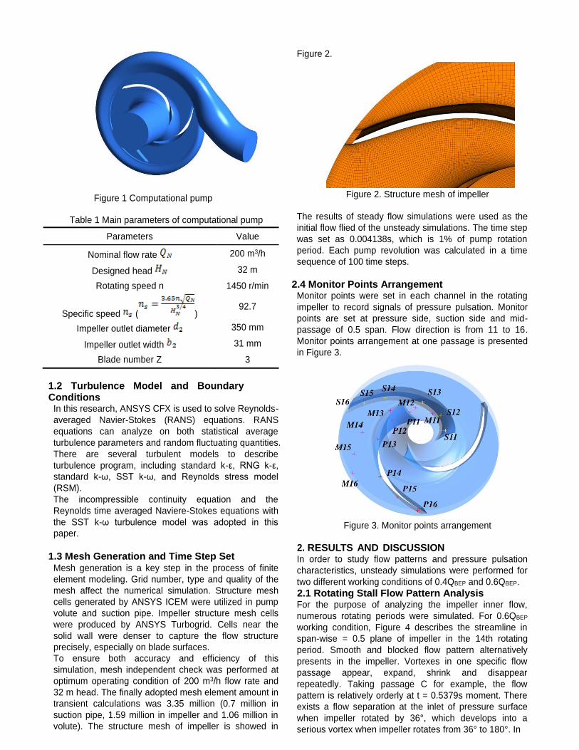
Figure 1 Computational pump
Table 1 Main parameters of computational pump
1.2 Turbulence Model and Boundary Conditions
In this research, ANSYS CFX is used to solve Reynolds-
averaged Navier-Stokes (RANS) equations. RANS
equations can analyze on both statistical average
turbulence parameters and random fluctuating quantities.
There are several turbulent models to describe
turbulence program, including standard k-ε, RNG k-ε,
standard k-ω, SST k-ω, and Reynolds stress model
(RSM).
The incompressible continuity equation and the
Reynolds time averaged Naviere-Stokes equations with
the SST k-ω turbulence model was adopted in this
paper.
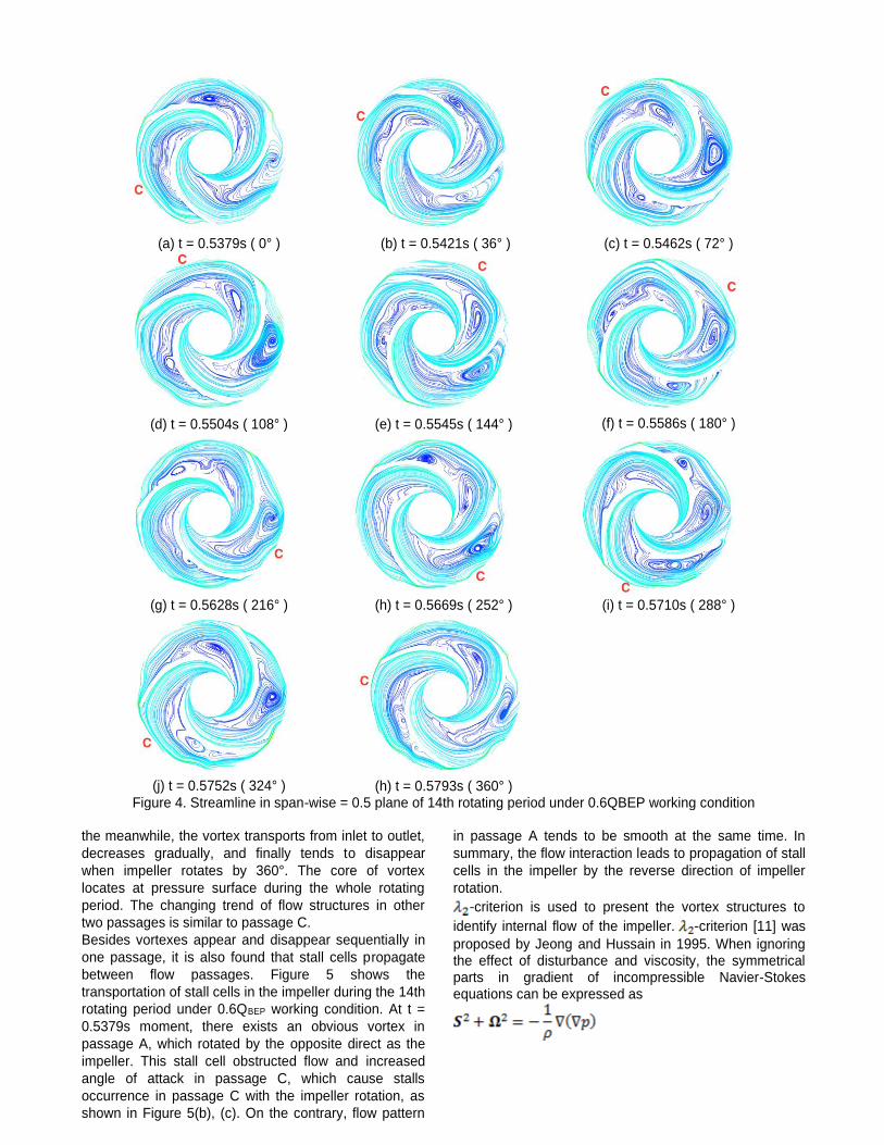
1.3 Mesh Generation and Time Step Set Mesh generation is a key step in the process of finite
element modeling. Grid number, type and quality of the
mesh affect the numerical simulation. Structure mesh
cells generated by ANSYS ICEM were utilized in pump
volute and suction pipe. Impeller structure mesh cells
were produced by ANSYS Turbogrid. Cells near the
solid wall were denser to capture the flow structure
precisely, especially on blade surfaces.
To ensure both accuracy and efficiency of this
simulation, mesh independent check was performed at
optimum operating condition of 200 m3/h flow rate and
32 m head. The finally adopted mesh element amount in
transient calculations was 3.35 million (0.7 million in
suction pipe, 1.59 million in impeller and 1.06 million in
volute). The structure mesh of impeller is showed in
Figure 2.
The results of steady flow simulations were used as the
initial flow flied of the unsteady simulations. The time step
was set as 0.004138s, which is 1% of pump rotation
period. Each pump revolution was calculated in a time
sequence of 100 time steps.
2.4 Monitor Points Arrangement Monitor points were set in each channel in the rotating
impeller to record signals of pressure pulsation. Monitor
points are set at pressure side, suction side and mid-
passage of 0.5 span. Flow direction is from 11 to 16.
Monitor points arrangement at one passage is presented
in Figure 3.
2. RESULTS AND DISCUSSION In order to study flow patterns and pressure pulsation
characteristics, unsteady simulations were performed for
two different working conditions of 0.4QBEP and 0.6QBEP.
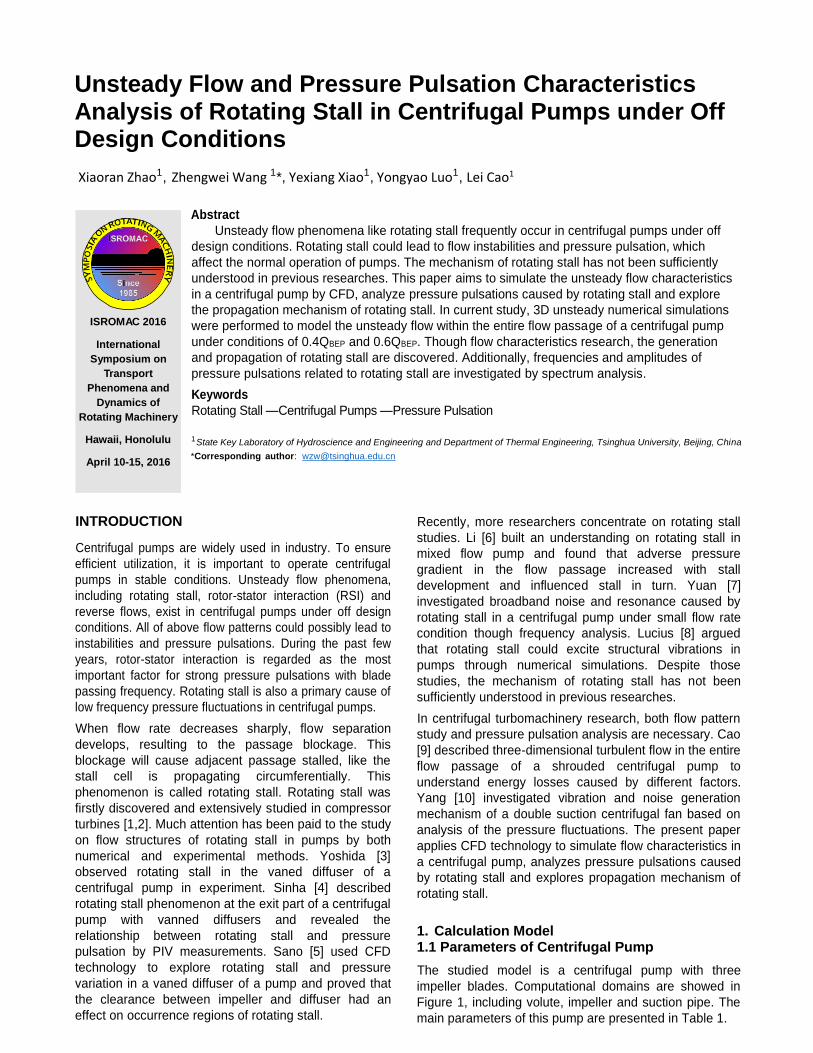
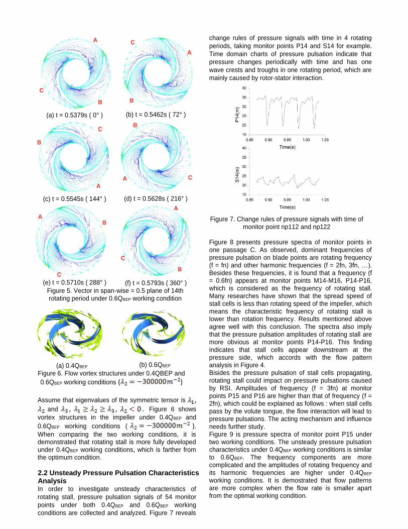
2.1 Rotating Stall Flow Pattern Analysis For the purpose of analyzing the impeller inner flow,
numerous rotating periods were simulated. For 0.6QBEP
working condition, Figure 4 describes the streamline in
span-wise = 0.5 plane of impeller in the 14th rotating
period. Smooth and blocked flow pattern alternatively
presents in the impeller. Vortexes in one specific flow
passage appear, expand, shrink and disappear
repeatedly. Taking passage C for example, the flow
pattern is relatively orderly at t = 0.5379s moment. There
exists a flow separation at the inlet of pressure surface
when impeller rotated by 36°, which develops into a
serious vortex when impeller rotates from 36° to 180°. In
Parameters Value
Nominal flow rate 200 m3/h
Designed head 32 m
Rotating speed n 1450 r/min
Specific speed ( ) 92.7
Impeller outlet diameter 350 mm
Impeller outlet width 31 mm
Blade number Z 3
Figure 2. Structure mesh of impeller
Figure 3. Monitor points arrangement
the meanwhile, the vortex transports from inlet to outlet,
decreases gradually, and finally tends to disappear
when impeller rotates by 360°. The core of vortex
locates at pressure surface during the whole rotating
period. The changing trend of flow structures in other
two passages is similar to passage C.
Besides vortexes appear and disappear sequentially in
one passage, it is also found that stall cells propagate
between flow passages. Figure 5 shows the
transportation of stall cells in the impeller during the 14th
rotating period under 0.6QBEP working condition. At t =
0.5379s moment, there exists an obvious vortex in
passage A, which rotated by the opposite direct as the
impeller. This stall cell obstructed flow and increased
angle of attack in passage C, which cause stalls
occurrence in passage C with the impeller rotation, as
shown in Figure 5(b), (c). On the contrary, flow pattern
in passage A tends to be smooth at the same time. In
summary, the flow interaction leads to propagation of stall
cells in the impeller by the reverse direction of impeller
rotation.
-criterion is used to present the vortex structures to
identify internal flow of the impeller. -criterion [11] was
proposed by Jeong and Hussain in 1995. When ignoring the effect of disturbance and viscosity, the symmetrical parts in gradient of incompressible Navier-Stokes equations can be expressed as
(a) t = 0.5379s ( 0° ) (b) t = 0.5421s ( 36° ) (c) t = 0.5462s ( 72° )
(d) t = 0.5504s ( 108° ) (e) t = 0.5545s ( 144° ) (f) t = 0.5586s ( 180° )
(g) t = 0.5628s ( 216° ) (h) t = 0.5669s ( 252° ) (i) t = 0.5710s ( 288° )
(j) t = 0.5752s ( 324° ) (h) t = 0.5793s ( 360° ) Figure 4. Streamline in span-wise = 0.5 plane of 14th rotating period under 0.6QBEP working condition
(a) t = 0.5379s ( 0° ) (b) t = 0.5462s ( 72° )
(c) t = 0.5545s ( 144° ) (d) t = 0.5628s ( 216° )
(e) t = 0.5710s ( 288° ) (f) t = 0.5793s ( 360° ) Figure 5. Vector in span-wise = 0.5 plane of 14th rotating period under 0.6QBEP working condition
Assume that eigenvalues of the symmetric tensor is ,
and , , . Figure 6 shows
vortex structures in the impeller under 0.4QBEP and
0.6QBEP working conditions ( ). When comparing the two working conditions, it is demonstrated that rotating stall is more fully developed under 0.4QBEP working conditions, which is farther from the optimum condition.
2.2 Unsteady Pressure Pulsation Characteristics Analysis In order to investigate unsteady characteristics of
rotating stall, pressure pulsation signals of 54 monitor
points under both 0.4QBEP and 0.6QBEP working
conditions are collected and analyzed. Figure 7 reveals
change rules of pressure signals with time in 4 rotating
periods, taking monitor points P14 and S14 for example.
Time domain charts of pressure pulsation indicate that
pressure changes periodically with time and has one
wave crests and troughs in one rotating period, which are
mainly caused by rotor-stator interaction.
Figure 7. Change rules of pressure signals with time of
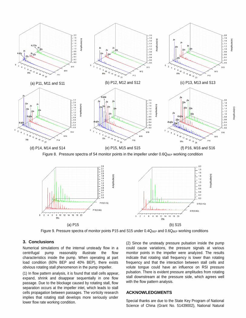
monitor point np112 and np122 Figure 8 presents pressure spectra of monitor points in one passage C. As observed, dominant frequencies of pressure pulsation on blade points are rotating frequency (f = fn) and other harmonic frequencies (f = 2fn, 3fn, …). Besides these frequencies, it is found that a frequency (f = 0.6fn) appears at monitor points M14-M16, P14-P16, which is considered as the frequency of rotating stall. Many researches have shown that the spread speed of stall cells is less than rotating speed of the impeller, which means the characteristic frequency of rotating stall is lower than rotation frequency. Results mentioned above agree well with this conclusion. The spectra also imply that the pressure pulsation amplitudes of rotating stall are more obvious at monitor points P14-P16. This finding indicates that stall cells appear downstream at the pressure side, which accords with the flow pattern analysis in Figure 4. Bisides the pressure pulsation of stall cells propagating, rotating stall could impact on pressure pulsations caused by RSI. Amplitudes of frequency (f = 3fn) at monitor points P15 and P16 are higher than that of frequency (f = 2fn), which could be explained as follows : when stall cells pass by the volute tongue, the flow interaction will lead to pressure pulsations. The acting mechanism and influence needs further study. Figure 9 is pressure spectra of monitor point P15 under two working conditions. The unsteady pressure pulsation characteristics under 0.4QBEP working conditions is similar to 0.6QBEP. The frequency components are more complicated and the amplitudes of rotating frequency and its harmonic frequencies are higher under 0.4QBEP working conditions. It is demostrated that flow patterns are more complex when the flow rate is smaller apart from the optimal working condition.
(a) 0.4QBEP (b) 0.6QBEP
Figure 6. Flow vortex structures under 0.4QBEP and
0.6QBEP working conditions ( )
3. Conclusions
Numerical simulations of the internal unsteady flow in a
centrifugal pump reasonably illustrate the flow
characteristics inside the pump. When operating at part
load condition (60% BEP and 40% BEP), there exists
obvious rotating stall phenomenon in the pump impeller.
(1) In flow pattern analysis, it is found that stall cells appear,
expand, shrink and disappear sequentially in one flow
passage. Due to the blockage caused by rotating stall, flow
separation occurs at the impeller inlet, which leads to stall
cells propagation between passages. The vorticity research
implies that rotating stall develops more seriously under
lower flow rate working condition.
(2) Since the unsteady pressure pulsation inside the pump
could cause variations, the pressure signals at various
monitor points in the impeller were analyzed. The results
indicate that rotating stall frequency is lower than rotating
frequency and that the interaction between stall cells and
volute tongue could have an influence on RSI pressure
pulsation. There is evident pressure amplitudes from rotating
stall downstream at the pressure side, which agrees well
with the flow pattern analysis.
ACKNOWLEDGMENTS
Special thanks are due to the State Key Program of National
Science of China (Grant No. 51439002), National Natural
(a) P11, M11 and S11
(b) P12, M12 and S12
(c) P13, M13 and S13
(d) P14, M14 and S14
(e) P15, M15 and S15
(f) P16, M16 and S16
Figure 8. Pressure spectra of 54 monitor points in the impeller under 0.6QBEP working condition
(a) P15 (b) S15
Figure 9. Pressure spectra of monitor points P15 and S15 under 0.4QBEP and 0.6QBEP working conditions
Science Foundation of China (No. 51279083), Special
Funds for Marine Renewable Energy Projects (Grant No.
GHME2012GC02), State Key Laboratory of Hydroscience
and Engineering (Grant No. 2014-KY-05) for supporting the
present work.
REFERENCES
[1] Emmons, H.W., Pearson, C.F., and Grant, H.P. 1955,
Compressor Surge and Stall Propagation [J],
Transactions of the ASME, Vol. 79. [2] Day I J. Stall inception in axial flow compressors [J].
Journal of Turbomachinery, 1993, 115(1):1-9. [3] Yoshida, Y., Murakami, Y., Tsurusaki, H., and
Tsujimoto, Y., 1991, Rotating Stalls in Centrifugal
Impeller/Vaned Diffuser Systems [J], ASME, FED-
Vol. 107, pp. 125–130. [4] Sinha M, Pinarbasi A, Katz J. The Flow Structure
During Onset and Developed States of Rotating Stall
Within a Vaned Diffuser of a Centrifugal Pump [J].
Journal of Fluids Engineering, 2001, 123(3):490-499. [5] Sano T, Yoshida Y, Nakamura Y, et al. Numerical
Study of Rotating Stall in a Pump Vaned Diffuser [J].
Journal of Fluids Engineering, 2002, 124(2):363-370. [6] Li X, Yuan S, Pan Z, et al. Dynamic Characteristics
of Rotating Stall in Mixed Flow Pump [J]. Journal of
Applied Mathematics, 2013, 2013(20):4819-4828. [7] Yuan S, Yang J, Yuan J, et al. Experimental
investigation on the flow-induced noise under
variable conditions for centrifugal pumps [J].
Chinese Journal of Mechanical Engineering, 2012,
25(3):456-462. [8] Lucius A, Brenner G. Numerical Simulation and
Evaluation of Velocity Fluctuations During Rotating
Stall of a Centrifugal Pump [J]. Journal of Fluids
Engineering, 2011, 133(8):602-610. [9] Cao Lei, Zhang Yiyang, Wang Zhengwei, Xiao
Yexiang, Liu Changjun. Effect of axial clearance on
the energy performance of an enclosed-impeller
centrifugal pump with vice blades. Journal of Fluids
Engineering. 2015; 137(7):071101-071101-10. [10] Yang Jing, Meng Long, Zhou Lingjiu, Luo Yongyao,
Wang Zhengwei. Unsteady internal flow field
simulations in a double suction centrifugal fan,
Engineering Computations. 2013, 30(3): 345-356. [11] Chakraborty P, Balachandar S, Adrian R J. On the
relationships between local vortex identification
schemes[J]. Journal of Fluid Mechanics, 2005, 535:
189-214.