The Winding Road: WorldCat Local as Discovery Tool at the University of South Florida Libraries

1 | P a g e
Torq-PRO Winding Tool Operation Manual
CAUTION:
Before using this Torsion Spring Winding Tool (Torq-PRO) read this manual and
follow all of its safety rules and Operating Instructions. Failure to do so could
result in serious injury and or death. Torsion Engineering LLC cannot be held
liable for any misuse or potential injury caused by this tool.
WINDING TOOL SAFETY
GENERAL SAFETY- Safety is a combination of common sense, staying alert, and
knowing how to use your tool.
1) READ and become familiar with the entire Operator’s Manual. LEARN the
tools application, Limitations, and Possible Hazards.
2) KEEP WORK AREA CLEAN – cluttered areas and benches invite accidents
3) DO NOT USE IN DANGEROUS ENVIRONMENTS – Do not use this tool in
rain or snow. Keep work area well lit.
4) KEEP CHILDREN AWAY – all visitors and bystanders should be kept a safe
distance from work area.
5) DO NOT FORCE THE TOOL – It will do the job better and safer at the rate for
which it was designed
6) USE THE RIGHT TOOL – Do not force the tool or an attachment to do a job
for which it was not designed
7) WEAR PROPER APPAREL – Do not wear loose clothing, gloves, neckties,
rings, bracelets, or other jewelry which may get caught in moving parts. Nonslip
footwear is recommended. Wear Protective hair covering to contain long hair.
8) ALWAYS WEAR EYE PROTECTION – Any tool can throw foreign objects
into the eyes and could cause permanent eye damage. ALWAYS wear safety
Goggles (not glasses) that comply with ANSI Safety Standard Z87.1. Everyday
eyeglasses have only impact-resistant lenses. They ARE NOT safety glasses.
NOTE: Glasses or goggles not in compliance with ANSI Z87.1 could seriously
injure you when they break.
9) SECURE WORK – Use clamps or locking pliers to hold tool in position when
practical. It is safer than using your hand and it frees both hands to operate the
tool.
2 | P a g e
10) DISCONNECT TOOL FROM SPRING before servicing, and when changing
accessories such as winding hubs.
11) USE ONLY ACCESSORIES SUPPLIED BY TORSION ENGINEERING –
Consult Torsion Engineering LLC for recommended accessories for this tool.
The use of improper accessories may cause risk of injury to yourself or others.
12) CHECK FOR DAMAGED PARTS- Before further use of this tool, a guard, or
other part that is damaged should be carefully be checked by a service
professional at Torsion Engineering to determine that it will operate properly and
perform its intended function. If damaged, the tool must be sent to Torsion
Engineering for a safety evaluation of all moving parts. All guards or other
damaged parts must be properly repaired or replaced to ensure proper operation.
13) NEVER LEAVE THE TOOL UNATTENDED. REMOVE THE TOOL
FROM ITS POWER SOURCE, THE SPRING. Do not walk away from a tool
in use. Make sure your winding tool is properly removed from the spring when
you have completed using it.
14) DO NOT OVERREACH – Keep proper footing and balance at all times.
15) MAINTAIN TOOLS WITH CARE – Keep tools clean and free from debris for
safe and proper performance.
INSTRUCTIONS FOR WINDING TORSION SPRINGS:
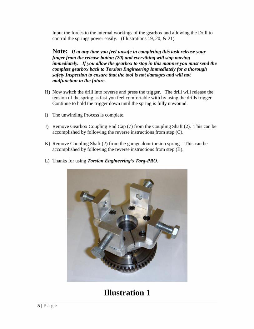
A) Install the correct winding hub size per (the winding hub sizing chart) onto the
coupling shaft. This is accomplished by removing the 6 bolts and changing
winding hubs to accommodate the different sizes of winding cones across the
industry. (Illustration 1)
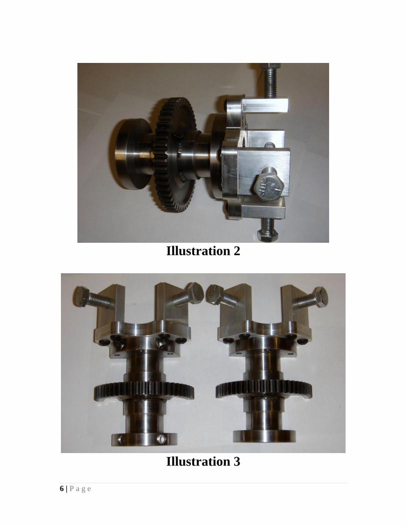
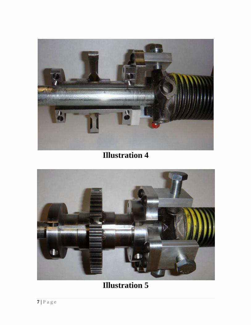
B) Install both halves of the Coupling Shaft (2) to the Garage Door Torsion Spring
above the garage door of the customer needing service. The Coupling Shaft
Locking Bolts (4) can already be installed on the Coupling Shaft (2). Hand
Tighten all 4 Locking Bolts (4) into the winding bar slots on the winding cone.
(Illustrations 2 , 3, 4, 5, & 6)
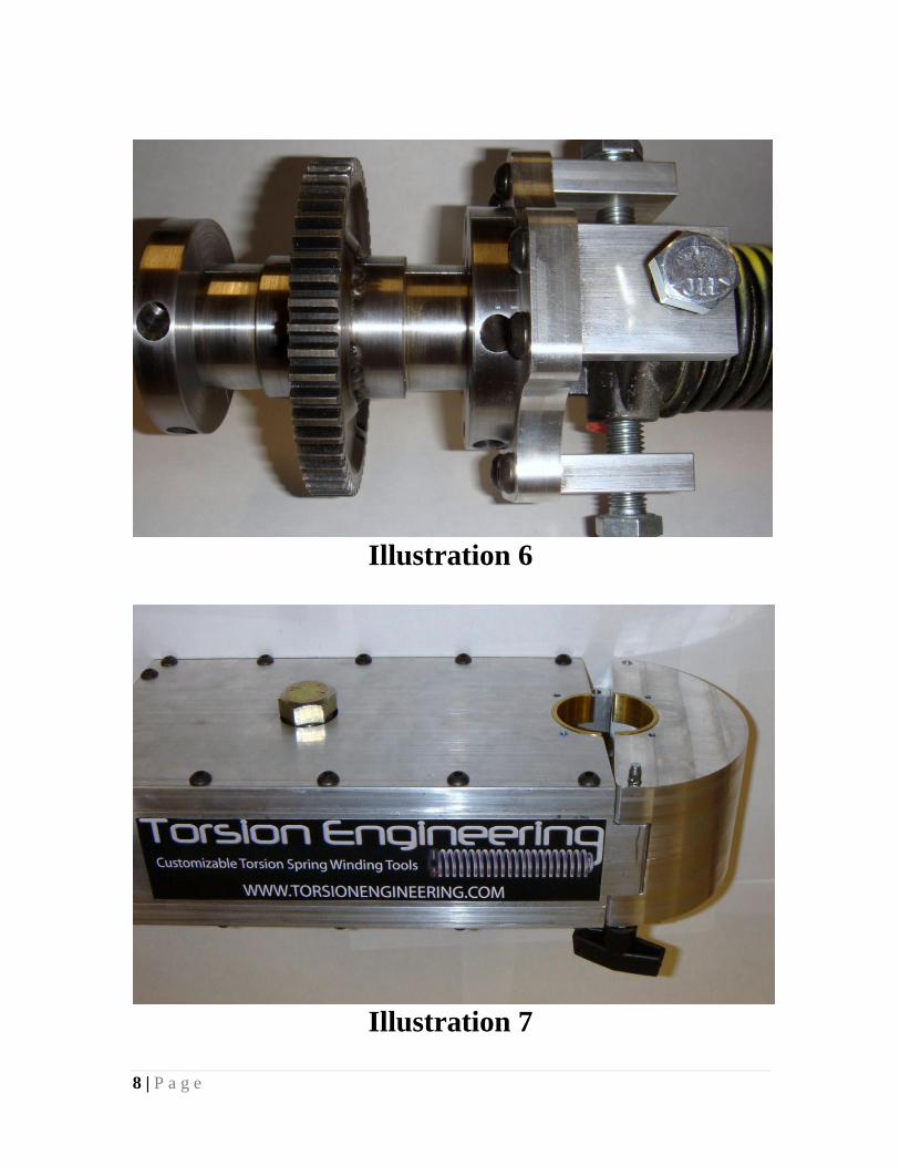
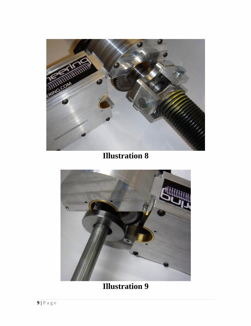
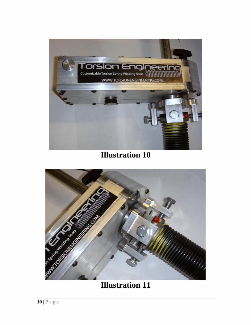
C) Next Take the Gearbox and remove the pin on the Gearbox Coupling End Cap
(7). Move Gearbox up to the Coupling Shaft (2) which is already installed on the
garage door torsion spring. Use the Gearbox Coupling End Cap (7) and wrap
them around the Coupling Shaft (2) in the proper location and close the end cap,
reinstall the pin, thus securing the gearbox assembly to the Coupling Shaft (2).
(Illustrations 7, 8, 9, 10, & 11)
3 | P a g e
Note: Install the gearbox in the correct direction on the Coupling Shaft (2) to
wind the spring in the desired direction. Gearbox can attach the Coupling
shaft (2) in both directions to accommodate left and right wound springs.
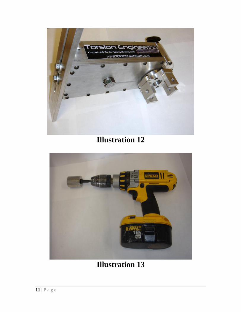
D) Adjust Sliding Lever Arm (12), if required, up or down to snug it to the garage
door inside face. This will lever the device on itself, therefore not allowing it to
spin when in use. (Illustration 12)
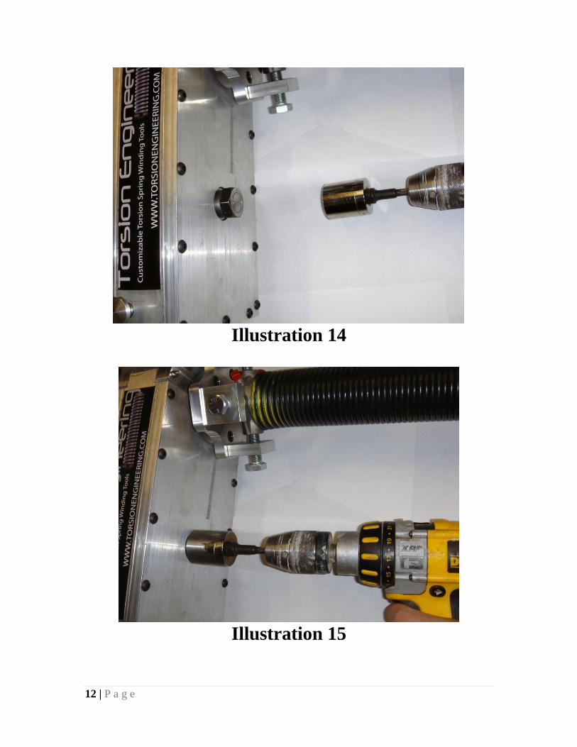
E) Now use an Electric Drill with socket attachment (Supplied by Others) and apply
force to the Input Driveshaft (14) from either side, in a winding direction only.
(Illustrations 13, 14, & 15)
Note: Attempting to apply force to the Input Driveshaft (14) in an unwinding
direction without releasing the ratcheting gear, by following the unwinding
directions below can cause internal damage to the gearbox thus making it
unusable.
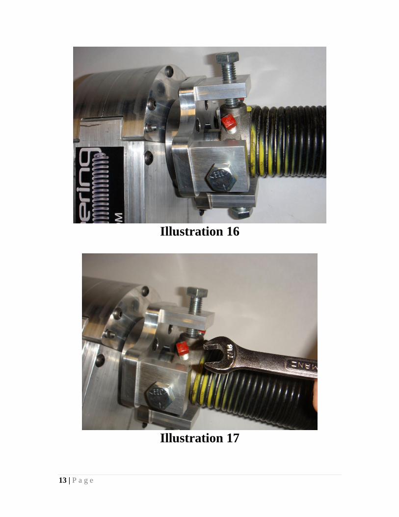
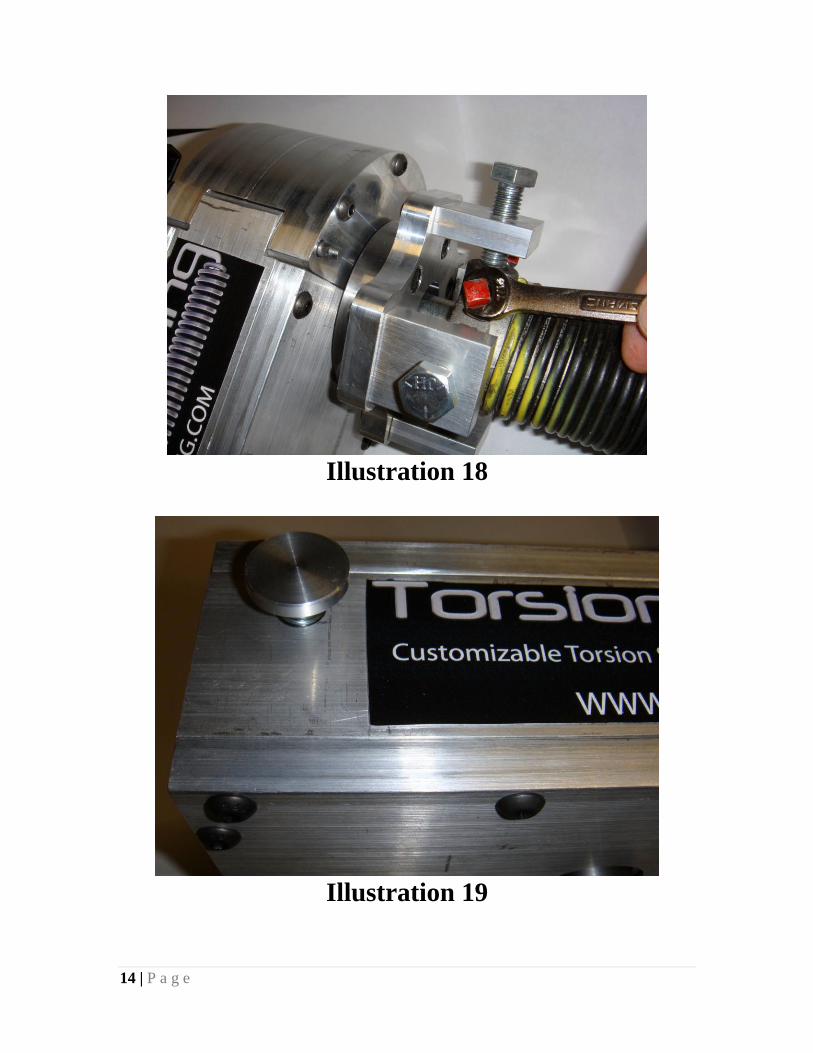
F) Continue to apply force with the electric drill until the spring is fully wound up
per manufactures spec, remove drill and stretch spring to desired location. Then
tighten the set screw on the Garage Door Torsion Spring to lock the spring in its
final location. (Illustrations 16, 17, & 18)
Note: If you over wind the spring please refer to the unwinding section below
to learn how to safely unwind the spring. You will be able to jump ahead to step
(F) in the unwinding section.
G) Remove Gearbox Coupling End Cap (7) from the Coupling Shaft (2). This can be
accomplished by following the reverse instructions from step (C).
H) Remove Coupling Shaft (2) from the garage door torsion spring. This can be
accomplished by following the reverse instructions from step (B).
I) Process is complete. Thanks for using Torsion Engineering’s Torq-PRO.
Please see our website for Demo Video’s at:
www.torsionengineering.com
4 | P a g e
INSTRUCTIONS FOR UN-WINDING TORSION SPRINGS:
A) Install the correct winding hub size per (the winding hub sizing chart) onto the
coupling shaft. This is accomplished by removing the 6 bolts and changing
winding hubs to accommodate the different sizes of winding cones across the
industry. (Illustration 1)
B) Install both halves of the Coupling Shaft (2) to the Garage Door Torsion Spring
above the garage door of the customer needing service. The Coupling Shaft
Locking Bolts (4) can already be installed on the Coupling Shaft (2). Hand
Tighten all 4 Locking Bolts (4) into the winding bar slots on the winding cone.
(Illustrations 2, 3, 4, 5, & 6)
C) Next Take the Gearbox and remove the pin on the Gearbox Coupling End Cap
(7). Move Gearbox up to the Coupling Shaft (2) which is already installed on the
torsion spring. Use the Gearbox Coupling End Cap (7) and wrap them around the
Coupling Shaft (2) in the proper location and close the end cap, reinstall the pin,
thus securing the gearbox assembly to the Coupling Shaft (2). (Illustrations 7, 8,
9, 10, & 11)
Note: Install the gearbox in the correct direction on the Coupling Shaft (2) to
wind the spring in the desired direction. Gearbox can attach the Coupling
shaft (2) in both directions to accommodate left and right wound springs.
D) Adjust Sliding Lever Arm (12), if required, up or down to snug it to the garage
door inside face. This will lever the device on itself, therefore not allowing it to
spin when in use. (Illustration 12)
E) Loosen the set screw on the Garage Door Torsion Spring to unlock the spring
from its previous location allowing it to transfer all the force onto the gears of the
gearbox. (Illustrations 16, 17, & 18)
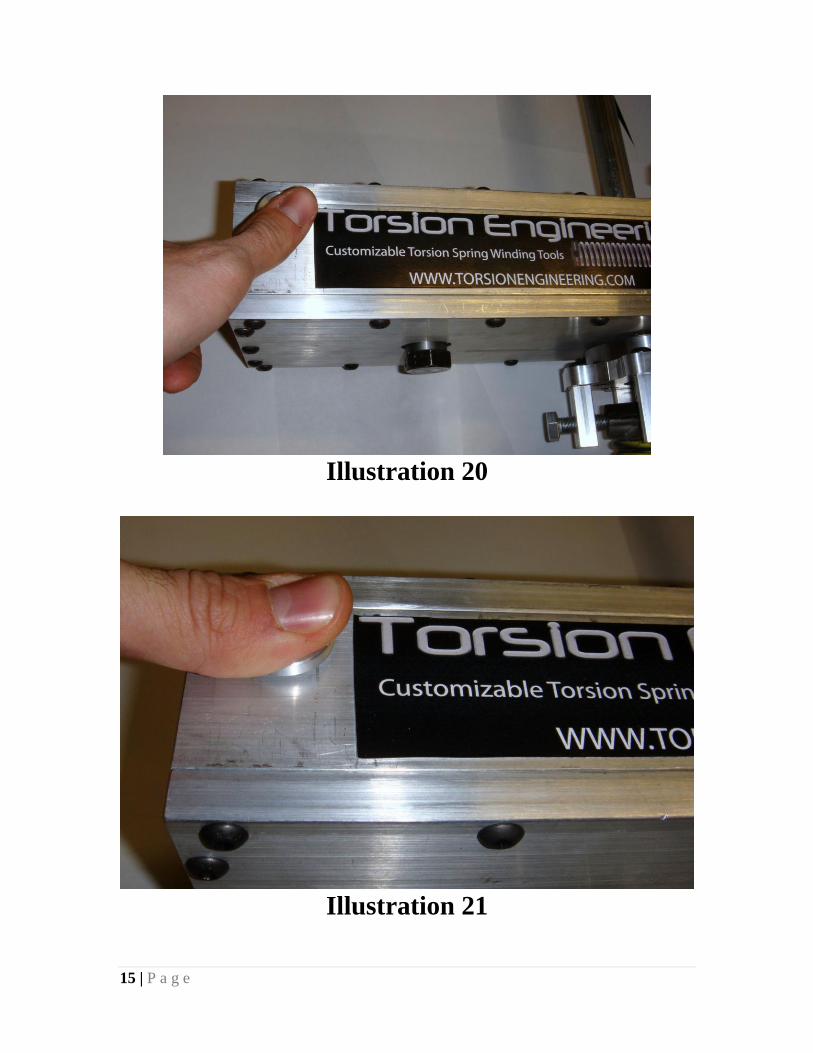
F) Now use an Electric Drill (WITH AN INTERNAL BRAKE ONLY) with socket
attachment (Supplied by Others) and apply force to the Input Driveshaft (14) in a
(winding) direction MANUALLY in order to take some of the force off the
internal ratchet gear. This will allow you to release the ratchet gear with the
release button (Illustrations 13, 14, 15,& 20)
Note: ALWAYS USE A DRILL THAT HAS AN INTERNAL BRAKE. FAILURE
TO DO SO WILL RESULT IN LACK OF CONTROL OF THE SPRING IN
UNWINDING SITUATIONS. (Most cordless drills have this brake feature)
G) Next hold the gearbox release button (20) on top of the box down fully to release
all the spring’s potential energy into the gearbox. This will allow the spring to
5 | P a g e
Input the forces to the internal workings of the gearbox and allowing the Drill to
control the springs power easily. (Illustrations 19, 20, & 21)
Note: If at any time you feel unsafe in completing this task release your
finger from the release button (20) and everything will stop moving
immediately. If you allow the gearbox to stop in this manner you must send the
complete gearbox back to Torsion Engineering Immediately for a thorough
safety Inspection to ensure that the tool is not damages and will not
malfunction in the future.
H) Now switch the drill into reverse and press the trigger. The drill will release the
tension of the spring as fast you feel comfortable with by using the drills trigger.
Continue to hold the trigger down until the spring is fully unwound.
I) The unwinding Process is complete.
J) Remove Gearbox Coupling End Cap (7) from the Coupling Shaft (2). This can be
accomplished by following the reverse instructions from step (C).
K) Remove Coupling Shaft (2) from the garage door torsion spring. This can be
accomplished by following the reverse instructions from step (B).
L) Thanks for using Torsion Engineering’s Torq-PRO.
Illustration 1
6 | P a g e
Illustration 2
Illustration 3
7 | P a g e
Illustration 4
Illustration 5
8 | P a g e
Illustration 6
Illustration 7
9 | P a g e
Illustration 8
Illustration 9
10 | P a g e
Illustration 10
Illustration 11
11 | P a g e
Illustration 12
Illustration 13
12 | P a g e
Illustration 14
Illustration 15
13 | P a g e
Illustration 16
Illustration 17
14 | P a g e
Illustration 18
Illustration 19
15 | P a g e
Illustration 20
Illustration 21